Embed Size (px)
Citation preview

T&T Pump Co., Inc
Rt. 8 Box 343 Fairmont, WV 26554
Phone (304) 366-1300 Fax (304) 366-1398
GENERAL OPERATION AND MAINTENANCE
MANUAL FOR THE T&T HORIZONTAL BEARING
FRAME BOOSTER PUMP LINE
H72, H74, H75, NH76, NH77, NH80, NH81, NH82, NH83, H85, H86
Rev. 10.26.09
1

Contents 1. Introduction 2. T&T Multistage Centrifugal Pumps 3. Model Number Designations 4. Most common problem situations 5. Special Warnings 6. Receiving Inspection 7. Storage 8. Pump Installation 9. Start-up Procedure 10. Initial Operation 11. Troubleshooting 12. T&T Pump Field Maintenance 13. Removal and Installation of Pump End 14. Cartridge Assembly Replacement 15. Casing Adapter Removal and Installation 16. Mechanical Seal Replacement 17. Bearing Frame Replacement 18. Bearing Lubrication 19. Motor Lubrication 20. Couplings 21. Field Monitoring 22. Temperatures 23. Pump Performance 24. Vibration 25. T&T Service Policy 26. Procedure for Returning a Pump 27. Dimensional Drawings 28. Replacement Parts 29. Recommended Spare Parts 30. General Exploded Views 31. Warranty 32. Appendices Addendum Service bulletins
2

1. Introduction T&T pumps are designed to give years of reliable service if properly installed and maintained. The life and satisfactory service of any pump is enhanced and extended by correct application, proper installation, periodic inspection, and careful maintenance. This manual was prepared to assist the operator in understanding the correct methods of installing, operating and maintaining a T&T pump. It is strongly recommended that this manual be read thoroughly prior to installing or performing any work on the pump or motor. Keep this manual on hand for further reference. Additional information on T&T pumps may be obtained by contacting T&T Pump Co. Inc., Rt. 8 Box 343, Fairmont, West Virginia 26554.
2. T&T Multistage Centrifugal Pumps T&T multistage centrifugal booster pumps are engineered to give dependable long lasting service and cover a broad range of flows and pressures. The T&T pump offers many features that will ensure ease of maintenance and less down time than other companies’ pumps. FEATURES:
• Modular design • Heavy duty threadless one piece casing • Victaulic inlet and discharge connections are standard • The inlet can be rotated in 90 degree increments to meet any application requirement • All wetted parts are available in 304 s/s or 316s/s, and with glass-filled Noryl or Stainless
Steel staging. • All motors are rated full load, continuous duty. • The standard sleeve bearing is of composite type, is chemically inert, and has a max
temp of 480 F. • Shimless replaceable cartridge assembly (SRC) allows for quick serviceability of pump
stack. • Heavy-duty bearing frame allows for maximum bearing life at max thrust loads.
T&T Pump’s unique modular design allows the pump to be built to the users specified performance and application. This allows the pump to achieve the highest pumping efficiency and customer satisfaction.
APPLICATIONS:
• Reverse Osmosis • Desalination • Ultra filtration • Deionized Water Distribution, Recirculation • Mining Dust Suppression • Wash down • Transfer Pumps • High Pressure Boosting • Jockey Pumps • Pulp and Paper Booster • Gas Chlorination • Filter Press • Spray systems
3

3. Model Number Designation
Ex. NH81E385X10E100A
NH 81 E 385 X 10 E 100 A Style H= Horizontal N= New
S= Submersible modular booster V= Vertical Product Line 72,74,75,76,77,79,80,81,82,83,85,86 Bearing frame A, B, C, D, E, G, H, K, T Impeller code Dependent upon product line (ex. 385=385gpm impeller) Material of construction F= 316 S/S with Noryl Impellers & Diffusers X= 316 S/S with 304 S/S Impellers and Diffusers Y= 316 S/S with 316 S/S Impellers and Diffusers Number of stages Dependent upon performance requirements Motor A= 1ph, ODP B= 3ph, ODP C=575V, ODP D= 1ph, TEFC E= 3ph, TEFC F= 575V, TEF G= special Horsepower ½ to 500 Frequency A= 60hz, 3600rpm (Nominal) B= 50hz, 2900rpm (Nominal)
4

4. Most Common Problem Situations Up Thrust Condition
Up thrust can occur when a pump is installed and run in a situation in which it will produce GREATER flow (GPM) than the pump was designed for (far right side of the performance curve). When such a pump is started, the initial thrust (upward surge of water) generated by the spinning impellers is so much greater than the downward thrust it is expecting to overcome, that the entire pump stack is lifted upwards (UPTHRUST). T&T pumps are manufactured with up thrust bearings that will handle intermittent upward water surges to a certain extent. If this condition continues, the pump components begin to absorb the up thrust as they grind against each other and eventually wear out within a much shorter life span than intended. Down Thrust Condition Down thrust can occur when a pump is installed and run in a situation in which it will produce HEAD in the range of shut off pressures (far left side of the performance curve). If this condition continues possible damage to the bearings in the pump and motor can occur. Down thrust is also an inefficient use of energy.
200
0
100
200
300
400
psi 500
Ft
0 150
50
150
250
350
450
300
250
400
350
500
450
550
GPM34.1
22.7 56.
845.4
79.5
68.1
102
90.8
114
125
M^3/hr
performance is based on 3600 (nominal) rpm, 60 hz motor. these pump curves and any individual curves, which are available upon request, are typical only and are not guaranteed as minimum performance. if exact flow and pressure are required, a certified curve may be ordered at additional cost if accompanied by an order and only after pump has been tested.
M
0
% Eff
5254565860626466687072747678
100
100
200
300
400
500
600
700
800
900
1000
1100
1200
100
200
300
1 − 10hp*
2 − 20hp*
3 − 30hp*
4 − 40hp*
5 − 50hp*
6 − 60hp*
7 − 75hp*
8 − 75hp*
9 − 100hp*
10 − 100hp*
11 − 125hp*
12 − 125hp*
13 − 125hp*
c frame
d frame
e frame
g frame
stages
DOWNTHRUSTMOST EFF. OPERATING
RANGEUPTHRUST
UPTHRUST/DOWNTHRUST
5

5. Special Warnings
!Caution!
To prevent hearing damage, wear hearing protection when in environments where sound levels are consistently above an 8-hour weighted average of
85 decibels or greater.
CAUTION
Read the start up instructions before starting this pump!
Max water temp! Water temperature should not exceed 85° F. Special bearings may be required for higher temperatures.
Do not run this pump dry! Inlet pressure should not be less than 10 psig for horizontal pumps and not less than 20 psig for inline booster module pumps. If the pressure is not available, contact factory for recommendations.
Install pressure gauges! Pressure gauges should be installed at the inlet and at the discharge. For present and future trouble shooting we must know the inlet and discharge pressures. Install flow meters! Flow meters should be installed immediately following throttle valves.
Never throttle pump at suction! This must be controlled at the discharge. Control valve at discharge! For proper control of flow and pressures, a control valve must be installed at the discharge end of the pump.
Designated flow range! Operation of pump at either the extreme right or left of the curve may cause damage to the pump. Operate the pump in the designated area of the performance curve.
Manually bleed air from the system! Install an air bleeder as close to the suction inlet as possible. Bleed the air from the system before starting the pumping system. Trapped air in the pump may cause immediate damage to the pump.
Check rotation! Jog pump motor (horizontal series) to check rotation. Pump shaft should rotate clockwise when viewed from motor end of pump. Reverse rotation may damage the pump. NOTE THAT THE H82 HAS A COUNTERCLOCKWISE ROTATION DURING OPERATION.
DO NOT OPERATE THIS PUMP MODEL #_________________________________________ ABOVE __________________________ PSI OR BELOW __________________________ PSI (REFER TO PUMP PERFORMANCE CURVE)
WARRANTY MAY BE VOIDED IF ABOVE CONDITIONS ARE NOT FOLLOWED
For start up assistance contact T&T Pump Co. Inc. immediately at (304) 366-1300
6
6. Receiving Inspection All pumps are tested and inspected at the factory prior to shipment to ensure the pump meets the requirement of your order. We suggest inspecting the pump upon arrival for possible damage due to shipping. If the pumps were not delivered in good order and in accordance with the Bill-of-loading, note the damage or shortage on both receipt and freight bill. MAKE ANY CLAIMS TO THE TRANSPORTATION COMPANY PROMPTLY. Please notify T&T Pump Co. Inc. as to the damage that the pumps received so that we may try to correct the problem. Instruction sheets as well as the operation and maintenance manual are included in shipment. DO NOT DISCARD!
7. Storage Store pumps in a cool dry place. Cover pump to insure pump and motor is protected from dust.
8. Pump Installation Location Install the pump as close as possible to the source of the liquid to be pumped. If the pump must be located several feet away or remote of the liquid source a transfer or feeder pump must be used to supply the pump with adequate liquid and inlet pressure. Floor space and headroom allotted for the pump must be sufficient for inspection and maintenance. Be sure to allow for crane or hoist service. Pump Foundation The foundation for the bedplate, motor, and pump must be sufficiently rigid and substantial to prevent significant vibration of the pump or deflection of the pump and motor shafts when operating the pump.
The recommended foundation should be either a reinforced concrete pad or a heavy steel skid frame. When using concrete it should support the skid at all points. When using a steel skid, the coupling must be re-aligned after any movement of the skid (see instructions on coupling alignment). The pump mounting is to be horizontal and the pump leveled within 1/16 in/ft to ensure that the oil level is equal on all bearings in the bearing frame. The pump case is the best reference for leveling. Motor, Pump, and Coupling Alignment for Direct Drive Pumps ACCURATE ALIGNMENT OF THE MOTOR, PUMP, AND COUPLING IS ESSENTIAL TO DEPENDABLE, LONG LASTING SERVICE.
T&T pumps leave the factory pre-leveled and pre-aligned, however final alignment of the motor, pump, and coupling is to be done after the bedplate is rigidly mounted and in its final operating position. Shipping as well as field handling may have changed the alignment. It is therefore essential to check the alignment before operating the pump.
If the pump has been supplied as a complete unit it will be necessary to remove the coupling guard to access the coupling. This may be done by loosening the two bolts on either side of the guard.
7

The coupling set screws should be tightened to 87 in * lbs. Measure the horizontal and vertical alignment using a straight edge. Align the coupling within 0.020” horizontally and vertically.
Measure the horizontal and vertical angular alignment measuring the gap on both sides of the coupling. Align the coupling faces to within 0.030” to 0.060” of parallel.
For best coupling life, keep the misalignment values near to zero as possible or within the specified ranges. This will also help ensure the trouble free life of the pump.
T&T offers a motor and pump adapter that helps eliminate misalignment between the pump and motor. Contact the factory for availability and pricing.
Coupling Guard Coupling guards come as an option on T&T pumps and are highly recommended. Check your plant safety guidelines for requirements. Piping The pump suction inlet has been designed to allow rotation in 90° increments (i.e. upright, left, and right). Remove the bolts that secure the inlet to the bearing frame and loosen the front foot bolt. Rotate the inlet in 90° increments to the desired position. Pipe plugs are incorporated into the design of the inlet to allow any air to be vented from the inlet when rotated. This must be done when the inlet is rotated away from the upright position and before starting the pump.
*Special note – BEFORE MAKING ANY MODIFICATIONS TO YOUR T&T PUMP, CONTACT THE FACTORY. YOU MUST DO THIS TO AVOID ANY POSSIBLE WARRANTY CONFLICTS.
The suction (inlet) piping should be of ample size, installed in direct runs, and have a minimum of bends to avoid pressure loss. This will also ensure the proper suction inlet pressure is maintained, 10 psig minimum for horizontal pumps and 20 psig for inline booster modules.
The pump inlet piping should be designed to avoid areas where air may become trapped, as this will disrupt pump priming and operation. Any change in pipe size ahead of the pump inlet should be tapered and reducers should be concentric to avoid air pockets.
The discharge piping should be designed to handle the maximum flows and pressures that the pump will produce.
All piping must be supported properly so that none of the piping weight is placed on the pump inlet or pump discharge.
The T&T pump is designed to accept victaulic-type fittings at the inlet and the discharge, which are standard on all pumps.
The coupling gasket on the victaulic-type clamps should be thoroughly lubricated before installation. Silicone grease is recommended, but make sure that this lubricant or any other will not harm your system.
8

9. Start-up Procedure Check for Free Turning Before the pump is started it is necessary to check to see if the pump turns freely by hand. Rotate the pump shaft by hand, between the pump and motor. If it cannot be turned by hand or rubbing and binding is noticed, correct before starting. Bearing Lubrication The pump bearings are lubricated using a static oil level within the bearing frame. The pump bearings may or may not be lubricated at the factory; this is dependent on method of shipment. It is essential that the bearing frame be checked for lubrication, the pump must not be run without lubrication. It may be necessary to add lubrication to the bearing frame even if the pump was shipped pre-lubricated. Refer to section 6.6, Bearing lubrication, for complete instructions and descriptions before proceeding with start-up. Priming The inlet piping and the pump must be filled with liquid before start-up. If the pump is below the liquid source or connected to a positive pressure source, the pump may be primed from that source.
Do not run the pump with a closed discharge valve (running against dead head) as the liquid can quickly heat up and exceed the maximum operating temperatures causing irreversible damage to the wetted parts of the pump end.
NEVER RUN THE PUMP DRY
To protect the pump from running dry, it is recommended that controls be used to protect the pump when in use. These controls include, but are not limited to: pressure switches, flow switches, and temperature switches.
Valves
Be sure that the suction valve is completely open. Normally, the discharge valve should be partially closed so the flow may be controlled. An operator should be present upon each start up to ensure the valves are correct.
Rotation Check
When initially connecting to the power source, be sure that the motor wiring and available line voltages are the same. Connect the wires as shown on the motor wiring diagram located on the inside of the motor junction box cover or on the nameplate label.
If the 3-phase motor is wired incorrectly, it will cause the pump to rotate in the wrong direction. This will result in low pressure and low flow (about ½ normal operation)
A motor starter is required for all 3-phase motors. Make sure that the pump is properly primed. Apply power for one second to check the rotation direction of the motor shaft. The motor shaft should turn in clockwise direction looking from the rear of the motor. Interchanging any two leads may change the direction.
9
10. Initial operation
Reduced Voltage Start-up
Motors used on reduced voltage starting should be carefully selected based upon power supply limitation and driven load requirements. The motors starting torque will be reduced when using reduced voltage starting. The elapsed time on the start step should be kept as short as possible and should not exceed 5 seconds. It is recommended that this time be limited to 2 seconds. Refer to the motor manufacturer for application assistance.
With the bearing frame lubricated, pump primed, and pump rotation checked, your pump is now ready to operate.
Operational Check Upon start-up check to see if the correct flow and pressure is obtained. Check the pump frequently during the first few hours of operation. The mechanical seal may weep slightly, especially if the pump has been in storage for any length of time. This should correct itself after it has time to “run in”, usually after a couple of hours. Check the pump bearings and motor for excessive heating. Check all of the plumbing for leaks. Do not run the pump beyond the maximum recommended flow as up-thrust may cause damage to the bearings. Shut down Procedure If the pump is equipped with check valves, it can be shut down without closing any valves. If no check valve is present, then it is necessary to close the discharge valve to prevent back flow through the pump.
11. Troubleshooting Pump will not start
Check to make sure all connections are correct and that there is power to the control box.
Check to make sure all circuit breakers or fuses are working and are they properly sized for the current they’ll be carrying. Check motor and pump to make sure neither are bound and can rotate freely. Pump starts but breaker trips
The motor may be overloaded. Check to verify that the motor is sized correctly for the flow and pressure it will be ran at.
Check to verify that the voltage is neither to high or to low. Either condition can cause overloads and breakers to trip. Make sure the pump is properly lubricated and not binding. Check to see if the pump is clogged with solids.
Verify all valves are open and or set properly. Never run the pump dry. Dry running can damage the pump.
10

Pump does not deliver water
Verify the pump has been primed and purged of all air.
Verify that all valves are open and the pump is not deprived of water. Check to see if valves are installed properly.
Check all strainers in the system to make sure water can flow freely.
Make sure the pump is running at the proper rotation. The pump should rotate in a clockwise direction looking from rear of motor.
Check performance curve to make sure pump is not running at shut off.
Inspect the coupling to see if it is loose on the pump or motor shaft.
Verify that the motor is running at the proper speed for the pump. Motor speed can greatly effect pump performance. Pump runs, but at reduced capacity or head
Pump may be running backwards. Check rotation.
Check performance against the pump performance curve to verify that the pump is not running at shut off. Pump may be undersized for the application.
Check for system bypassing. Inspect all relief valves and by-pass gate or globe valves for correct settings.
Check for leaking or broken pipe in discharge system.
Discharge piping may be partially plugged with chemical deposits.
Strainer or filter system may be partially plugged or need cleaning or replacing.
Pump may be worn by pumping abrasive materials. The pump may need repaired or replaced. Troubleshooting Assistance
If you need to contact a service center, please have the following information to help the technician define your problem.
Pump model, size, and serial number.
Date pump was received and date installed. How long did the pump run before problem arose?
What is the actual voltage being used? What is the amperage when the pump is running? Was the electrical circuit checked for grounds or open circuits? How many starts per hour does the pump perform?
11
If you are still experiencing problems after checking the trouble shooting section, please contact T&T Pump Co. Inc. at 304-366-1300 for the service center near you.
12. T&T Pump Field Maintenance The horizontal series T&T pump is made of three basic modules: the pump end assembly, the casing adapter assembly, and the bearing frame assembly. Each module can be replaced without completely disassembling the pump. T&T offers a series of repair videos that cover the H80 and H81 product lines. These videos may be obtained by contacting T&T Pump Co., Inc. Additional product line videos are currently in production.
DISCONNECT AND LOCKOUT ALL POWER BEFORE SERVICING THE PUMP
13. Removal and Installation of Pump End
Removal
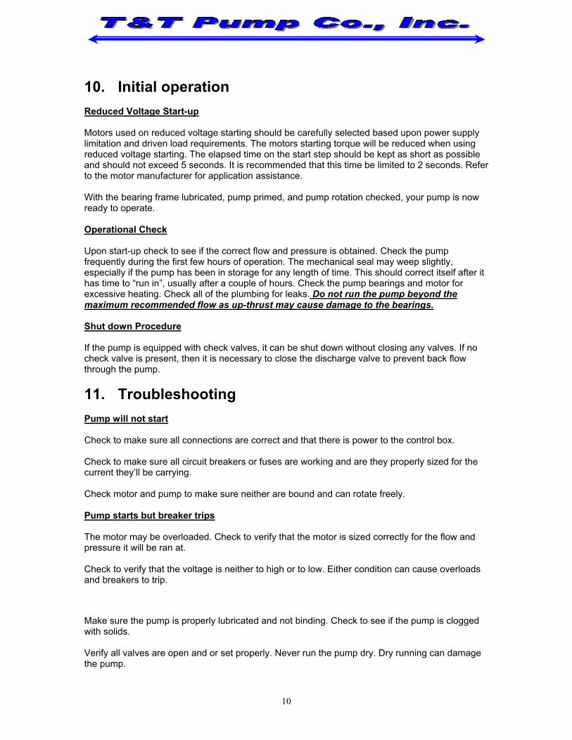
Steps:
Remove the front foot mounting bolts.
Remove the casing bolts that secure the pump casing assembly to the casing adapter assembly.
12

Separate the pump casing assembly from the casing adapter assembly. Do not pull the casing off of the pump staging. The pump casing assembly and the pump staging must be removed together. The pump shaft has a hex end, which plugs into the shaft coupler. There are no threads so the shaft will simply pull out of the shaft coupler. Be careful not to damage the o-ring that seals the pump casing and the casing adapter. Do not discard the o-ring. Use two people to remove the casing assembly.
Installation
Installation is the reverse of removal. Be sure to include the o-ring when installing the pump casing assembly.
13
14. Cartridge Assembly Replacements
Removal of Cartridge Assembly
Steps:
Remove the front foot mounting bolts. Remove the casing bolts that secure the pump casing assembly to the casing adapter assembly. Separate the pump casing assembly from the casing adapter assembly. Do not pull the casing off of the pump staging. The pump casing assembly and the pump staging must be removed together. The pump shaft has a hex end, which plugs into the shaft coupler. There are no threads so the shaft will simply pull out of the shaft coupler. Be careful not to damage the o-ring that seals the pump casing and the casing adapter. Do not discard the o-ring. Use two people two remove the casing assembly.
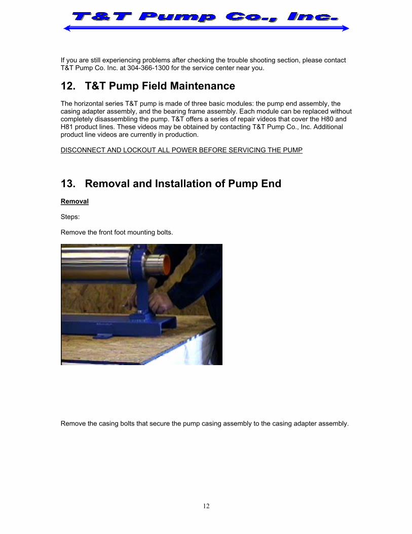
Once the pump casing assembly has been removed have one person hold the casing and one person pull the old cartridge assembly from the pump casing assembly. Replacement of the Cartridge Assembly Place the new cartridge assembly vertically onto support blocks or support fixture with the hex end of the shaft down. Be careful not to damage the pump shaft in any way. Check each diffuser to ensure all diffusers are engaged. Check to ensure that the up-thrust washer is resting on the bearing runner. With the cartridge assembly resting vertically on the support blocks, slide the pump casing assembly over the cartridge assembly. Be careful to line up the bearing runner up with the sleeve bearing inside the casing.
14

With the cartridge assembly and the pump casing assembly resting vertically on the support blocks, check the dimension from bottom of the first stage to the face of the pump casing assembly flange. This dimension should be no more than 0.030”. If the dimension is larger check to make sure all of the diffusers are properly engaged.
15. Casing Adapter Removal and Installation
Removal
Steps:
Remove the front foot mounting bolts.
Remove the casing bolts that secure the pump casing assembly to the casing adapter assembly. Separate the pump casing assembly from the casing adapter assembly. Do not pull the casing off of the pump staging. The pump casing assembly and the pump staging must be removed together. The pump shaft has a hex end, which plugs into the shaft coupler. There are no threads so the shaft will simply pull out of the shaft coupler. Be careful not to damage the o-ring that seals the pump casing and the casing adapter. Do not discard the o-ring. Use two people two remove the casing assembly.
15
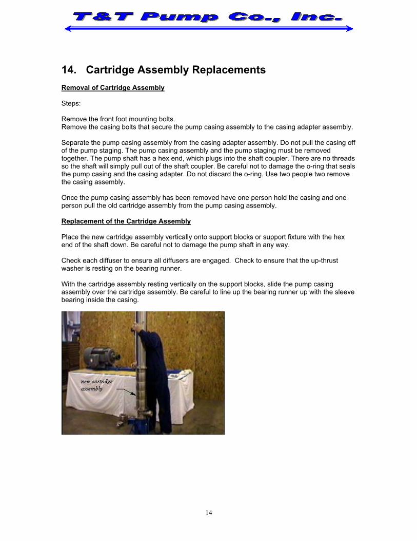
Once the pump casing assembly has been removed, remove the bolts and lock washers that secure the casing adapter to the bearing frame.
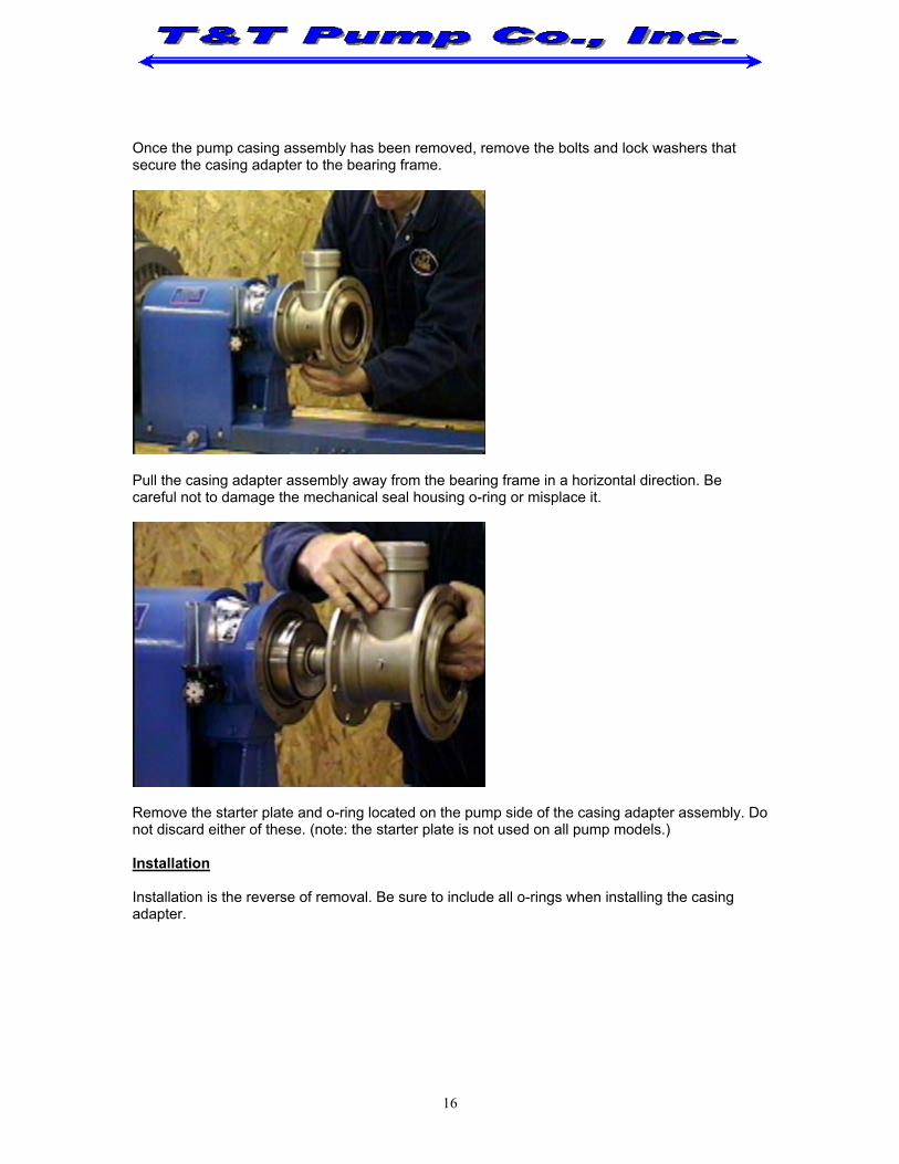
Pull the casing adapter assembly away from the bearing frame in a horizontal direction. Be careful not to damage the mechanical seal housing o-ring or misplace it.
Remove the starter plate and o-ring located on the pump side of the casing adapter assembly. Do not discard either of these. (note: the starter plate is not used on all pump models.) Installation
Installation is the reverse of removal. Be sure to include all o-rings when installing the casing adapter.
16

16. Mechanical Seal Replacement
Removal
It is only necessary to remove the mechanical seal when the bearing frame assembly is not being replaced and the mechanical seal is the only defective equipment. Steps:
Remove the front foot mounting bolts.
Remove the casing bolts that secure the pump casing assembly to the casing adapter assembly. Separate the pump casing assembly from the casing adapter assembly. Do not pull the casing off of the pump staging. The pump casing assembly and the pump staging must be removed together. The pump shaft has a hex end, which plugs into the shaft coupler. There are no threads so the shaft will simply pull out of the shaft coupler. Be careful not to damage the o-ring that seals the pump casing and the casing adapter. Do not discard the o-ring. Use two people to remove the casing assembly. Once the pump casing assembly has been removed, remove the bolts and lock washers that secure the casing adapter to the bearing frame. Pull the casing adapter assembly away from the bearing frame in a horizontal direction. Be careful not to damage the mechanical seal housing o-ring or misplace it. Remove the starter plate and o-ring located on the pump side of the casing adapter assembly. Do not discard either of these. (Note: the starter plate is not used on all pump models.) Once the pump casing assembly and the casing adapter assembly have been removed, the mechanical seal will be exposed and ready for removal.
17

With a pair of spring clip pliers, remove the spring clip located at the end of the shaft coupler that the seal rest upon. Do not discard the spring clip. Once the spring clip has been removed the mechanical seal can be removed from the shaft coupler. The mechanical seal consists of two separate parts, the spring and the stationary base. Remove both.
Installation
Steps:
It is important that care be taken when handling mechanical seals. Any damage to the seal face will make the mechanical seal useless. The mechanical seal should be monitored for leakage. On the underside of the casing adapter is weep hole, any leakage from the mechanical seal will be noticed at this location. It is important to note that the mechanical seal may weep slightly during the first few hours of operation, especially if the pump has been in storage for any length of time. Taking care not to damage the face of the seal, place the base of the seal over the shaft coupler and into its resting position on the mechanical seal housing. Again, taking care not to damage the face of the seal, place the spring portion of the seal over the shaft coupler until it rests upon the base of the seal.
18

Depress the spring so the spring clip can be replaced. Using the spring clip pliers, spread the spring clip over the shaft couple and place it into the groove. This will securely hold the mechanical seal into position.
17. Bearing Frame Replacement A qualified service technician should only service the bearing frame. When a new bearing frame is shipped for replacement it comes completely assembled.
Removal
Steps:
With the pump casing assembly and the casing adapter assembly removed, the bearing frame assembly may now be removed. If the motor and pump coupling guard is in place it must first be removed. With the coupling guard removed the coupling my be accessed. Using the proper allen wrench, loosen the sets crews that secure the coupling to the pump and motor shafts. Do not remove the set screws.
Slide the coupling on the motor shaft back towards the motor. Remove the rubber-coupling element. Do not discard. Remove the coupling from the bearing frame shaft.
19
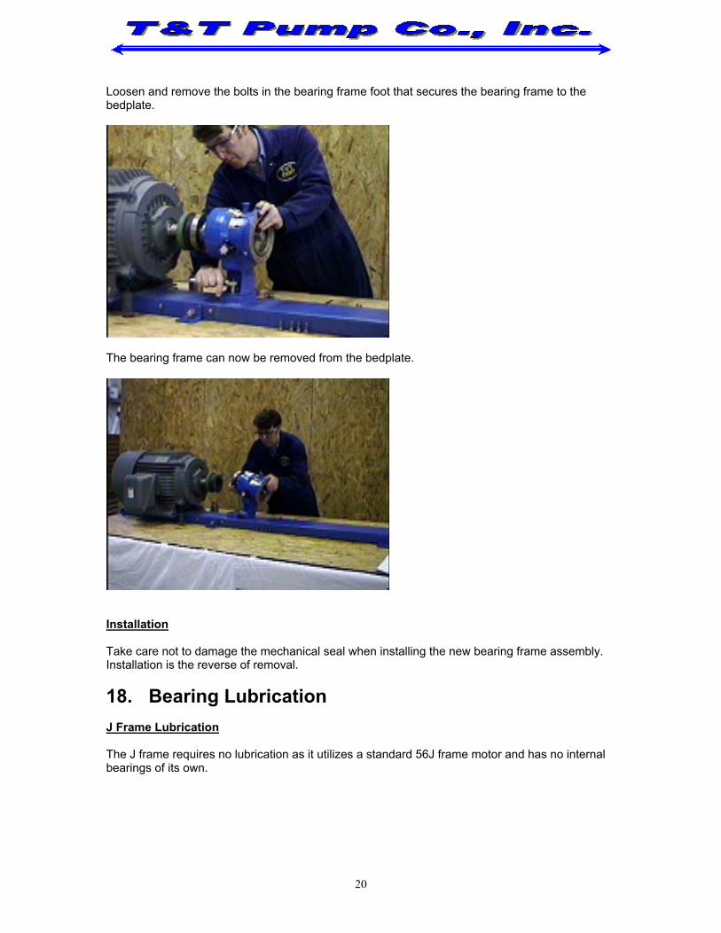
Loosen and remove the bolts in the bearing frame foot that secures the bearing frame to the bedplate.
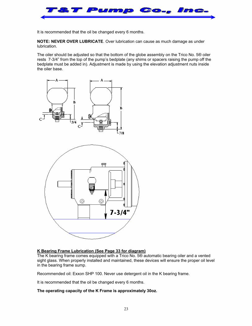
The bearing frame can now be removed from the bedplate.
Installation
Take care not to damage the mechanical seal when installing the new bearing frame assembly. Installation is the reverse of removal. 18. Bearing Lubrication J Frame Lubrication
The J frame requires no lubrication as it utilizes a standard 56J frame motor and has no internal bearings of its own.
20

A Frame Lubrication
The A frame requires no lubrication as it utilizes the motor’s internal bearings and has no internal bearings of its own. B Bearing Frame Lubrication
The B frame requires no lubrication as it uses a single radial bearing pre- lubricated by the bearing manufacturer.
C Bearing Frame Lubrication
The C frame is a grease-lubricated bearing frame and requires minimal maintenance to ensure long lasting service. NOTE: NEVER OVER LUBRICATE. Over lubrication can cause as much damage as under lubrication.
It is recommended that a calibrated grease gun be used so the proper amount of grease can be applied to the bearings (i.e. how many pumps required of the grease gun per 1 ounce of grease). The C bearing frame will be shipped pre-lubricated. When pump is in continuous operation it will only be necessary to give the bearing frame one full stroke of a standard grease gun per month. Replace grease every six months.
It is recommended that the bearing temperature be noted after the first hour of initial operation and checked periodically there after. As a rule of thumb temperature variation (i.e. a rise in temperature from the monitored operating temperature) will determine the need for bearing lubrication. Max operating temperature should not exceed 250°F. The recommended grease for the C bearing frame:
EXXON RONEX MP NLGI Grade No. 2 lithium complex greases or an exact equivalent DO NOT MIX OR USE ANY OTHER GREASE THAN RECOMMENDED
D Bearing Frame Lubrication (See Page 30 for diagram)
The pump bearings are lubricated using a static oil level within the bearing frame. The pump bearings may or may not be lubricated at the factory; this is dependent on method of shipment. It is essential that the bearing frame be checked for lubrication, the pump must not be run without lubrication. It may be necessary to add lubrication to the bearing frame even if the pump was shipped pre-lubricated The D-type bearing frame comes equipped with a vented oil gauge for monitoring the oil level. When properly installed and maintained, this device will monitor the proper oil level in the bearing frame sump. See Page 30 for proper oil level adjustment. Recommended oil: Exxon SHP 100. Never use detergent oil in the D bearing frame.
It is recommended that the oil be changed every 6 months.
The operating capacity of the D Frame is approximately 16oz. NOTE: NEVER OVER LUBRICATE. Over lubrication can cause as much damage as under lubrication.
21

E Bearing Frame Lubrication (See Page 31 for diagram)
The pump bearings are lubricated using a static oil level within the bearing frame. The pump bearings may or may not be lubricated at the factory; this is dependent on method of shipment. It is essential that the bearing frame be checked for lubrication, the pump must not be run without lubrication. It may be necessary to add lubrication to the bearing frame even if the pump was shipped pre-lubricated
The E-type bearing frame comes equipped with a vented oil gauge for monitoring the oil level. When properly installed and maintained, this device will monitor the proper oil level in the bearing frame sump. See Page 31 for proper oil level adjustment. Recommended oil:
Exxon SHP 100.
Never use detergent oil in the E bearing frame.
It is recommended that the oil be changed every 6 months. The operating capacity of the E Frame is approximately 12oz. NOTE: NEVER OVER LUBRICATE. Over lubrication can cause as much damage as under lubrication. G Bearing Frame Lubrication (See Page 32 for diagram)
The pump bearings are lubricated using a static oil level within the bearing frame. The pump bearings may or may not be lubricated at the factory; this is dependent on method of shipment. It is essential that the bearing frame be checked for lubrication, the pump must not be run without lubrication. It may be necessary to add lubrication to the bearing frame even if the pump was shipped pre-lubricated
The G type bearing frame comes equipped with a vented oil gauge for monitoring the oil level. When properly installed and maintained, this device will monitor the proper oil level in the bearing frame sump. See Page 32 for proper oil level adjustment. Recommended oil: Exxon SHP 100. Never use detergent oil in the G bearing frame.
It is recommended that the oil be changed every 6 months. NOTE: NEVER OVER LUBRICATE. Over lubrication can cause as much damage as under lubrication. H Bearing Frame Lubrication The H bearing frame comes equipped with a Trico No. 5® automatic bearing oiler. When properly installed and maintained, this device will monitor the proper oil level in the bearing frame sump.
Always use the oiler bottle to fill the sump. Never pour directly into the housing of the oiler. The oiler bottle may have to be filled several times before the sump is completely filled. It is important not to over fill the bearing frame, this can cause foaming in the oil which will cause higher than normal operating temperatures. During normal operation the oiler bottle should be ½ to ¾ full.
Recommended oil: Exxon SHP 100. Never use detergent oil in the H bearing frame.
22
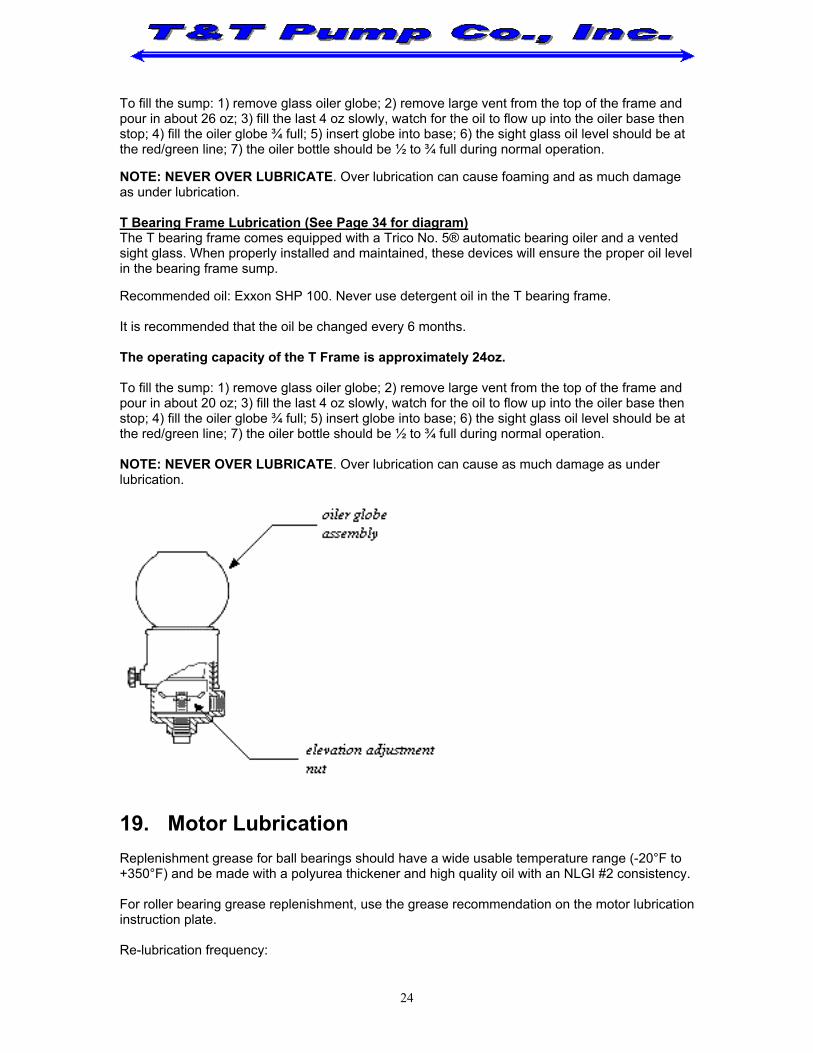
It is recommended that the oil be changed every 6 months. NOTE: NEVER OVER LUBRICATE. Over lubrication can cause as much damage as under lubrication. The oiler should be adjusted so that the bottom of the globe assembly on the Trico No. 5® oiler rests 7-3/4” from the top of the pump’s bedplate (any shims or spacers raising the pump off the bedplate must be added in). Adjustment is made by using the elevation adjustment nuts inside the oiler base.
K Bearing Frame Lubrication (See Page 33 for diagram) The K bearing frame comes equipped with a Trico No. 5® automatic bearing oiler and a vented sight glass. When properly installed and maintained, these devices will ensure the proper oil level in the bearing frame sump.
Recommended oil: Exxon SHP 100. Never use detergent oil in the K bearing frame. It is recommended that the oil be changed every 6 months. The operating capacity of the K Frame is approximately 30oz.
23
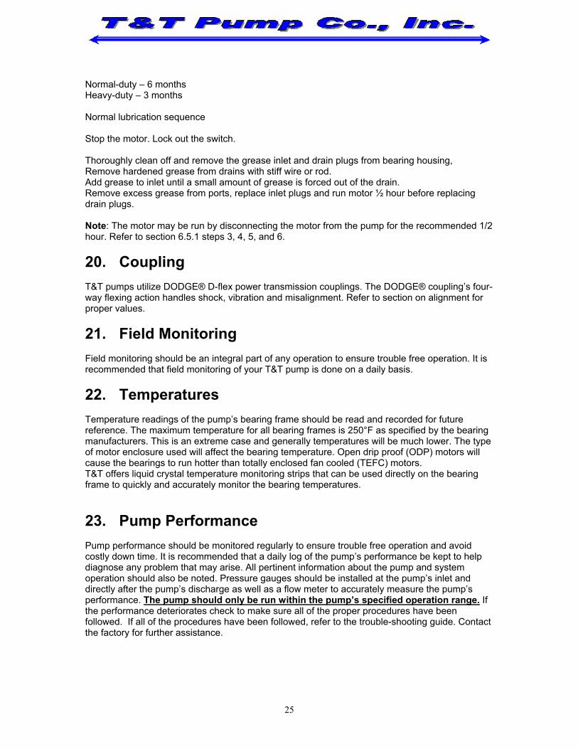
To fill the sump: 1) remove glass oiler globe; 2) remove large vent from the top of the frame and pour in about 26 oz; 3) fill the last 4 oz slowly, watch for the oil to flow up into the oiler base then stop; 4) fill the oiler globe ¾ full; 5) insert globe into base; 6) the sight glass oil level should be at the red/green line; 7) the oiler bottle should be ½ to ¾ full during normal operation. NOTE: NEVER OVER LUBRICATE. Over lubrication can cause foaming and as much damage as under lubrication. T Bearing Frame Lubrication (See Page 34 for diagram) The T bearing frame comes equipped with a Trico No. 5® automatic bearing oiler and a vented sight glass. When properly installed and maintained, these devices will ensure the proper oil level in the bearing frame sump.
Recommended oil: Exxon SHP 100. Never use detergent oil in the T bearing frame. It is recommended that the oil be changed every 6 months. The operating capacity of the T Frame is approximately 24oz. To fill the sump: 1) remove glass oiler globe; 2) remove large vent from the top of the frame and pour in about 20 oz; 3) fill the last 4 oz slowly, watch for the oil to flow up into the oiler base then stop; 4) fill the oiler globe ¾ full; 5) insert globe into base; 6) the sight glass oil level should be at the red/green line; 7) the oiler bottle should be ½ to ¾ full during normal operation. NOTE: NEVER OVER LUBRICATE. Over lubrication can cause as much damage as under lubrication.
19. Motor Lubrication
Replenishment grease for ball bearings should have a wide usable temperature range (-20°F to +350°F) and be made with a polyurea thickener and high quality oil with an NLGI #2 consistency. For roller bearing grease replenishment, use the grease recommendation on the motor lubrication instruction plate. Re-lubrication frequency:
24
Normal-duty – 6 months Heavy-duty – 3 months
Normal lubrication sequence
Stop the motor. Lock out the switch. Thoroughly clean off and remove the grease inlet and drain plugs from bearing housing, Remove hardened grease from drains with stiff wire or rod. Add grease to inlet until a small amount of grease is forced out of the drain. Remove excess grease from ports, replace inlet plugs and run motor ½ hour before replacing drain plugs.
Note: The motor may be run by disconnecting the motor from the pump for the recommended 1/2 hour. Refer to section 6.5.1 steps 3, 4, 5, and 6.
20. Coupling
T&T pumps utilize DODGE® D-flex power transmission couplings. The DODGE® coupling’s four-way flexing action handles shock, vibration and misalignment. Refer to section on alignment for proper values.
21. Field Monitoring
Field monitoring should be an integral part of any operation to ensure trouble free operation. It is recommended that field monitoring of your T&T pump is done on a daily basis.
22. Temperatures
Temperature readings of the pump’s bearing frame should be read and recorded for future reference. The maximum temperature for all bearing frames is 250°F as specified by the bearing manufacturers. This is an extreme case and generally temperatures will be much lower. The type of motor enclosure used will affect the bearing temperature. Open drip proof (ODP) motors will cause the bearings to run hotter than totally enclosed fan cooled (TEFC) motors. T&T offers liquid crystal temperature monitoring strips that can be used directly on the bearing frame to quickly and accurately monitor the bearing temperatures.
23. Pump Performance
Pump performance should be monitored regularly to ensure trouble free operation and avoid costly down time. It is recommended that a daily log of the pump’s performance be kept to help diagnose any problem that may arise. All pertinent information about the pump and system operation should also be noted. Pressure gauges should be installed at the pump’s inlet and directly after the pump’s discharge as well as a flow meter to accurately measure the pump’s performance. The pump should only be run within the pump’s specified operation range. If the performance deteriorates check to make sure all of the proper procedures have been followed. If all of the procedures have been followed, refer to the trouble-shooting guide. Contact the factory for further assistance.
25

24. Vibration
Vibration analysis enables the user to determine when “normal” vibration exceeds acceptable levels. It may also allow the user to determine the source and the cause of the problem, thus becoming an effective preventative maintenance tool and trouble shooting aid.
Severity of vibration is a function of amplitude and frequency. Any change in the severity of vibration over time is usually a warning of impending failure.
Complete vibration analysis requires taking vibration readings on the bearing frame in the horizontal and vertical planes and recording the information for future reference. Listed below are some guidelines for vibration ranges. Vibration velocity:
25. T&T Service Policy
The T&T Operation and Maintenance manual was written to assist you, the customer, in performing minor field maintenance and field repairs on T&T pumps. Proper maintenance will ensure long life and minimize down time. T&T pumps are designed and manufactured to make such field repairs quick and easy. Pump repairs may be made by the customer provided prior written and verbal approval by T&T Pump Co., Inc. has been obtained. Repairs may also be made by a T&T pump distributor with an approved maintenance shop or by returning the pump to the factory.
26

26. Procedure for Returning a Pump T&T Pump Co. Inc. requires that a CUSTOMER SERVICE DEPARTMENT RETURN AUTHORIZATION REQUEST FORM be filled out and submitted for authorization. Once the form has been received, a RETURN GOODS TAG (RGT#) number will be assigned to the pump. After these procedures have been completed the pump may be shipped to T&T and warranty determination will be made. For a CUSTOMER SERVICE DEPARTMENT RETURN AUTHORIZATION REQUEST FORM (RGT form) see Appendix B. Failure to follow these procedures may result in possible delays that can cause excessive down time for the end user.
27. Dimensional Drawings Dimensional drawings can be found in the T&T product catalogs or may be requested by contacting the factory. Please have the pump model number when contacting the factory.
28. Replacement Parts Replacement parts may be ordered through you local distributor or directly from: T&T Pump Co. Inc. Rt. 8 Box 343 Fairmont, WV 26554 Phone (304) 366-1300 Fax (304) 366-1398 When ordering parts please have the following information available: Model number of the pump Serial number of the pump Motor manufacturer, motor horsepower, frame size, and enclosure specification Part name Part description Special material of construction, if any
29. Recommended Spare Parts
(Refer to spec sheet and general exploded view) Bearing retainer o-ring Mechanical seal Mechanical seal housing o-ring Discharge assembly o-ring Pump casing/casing adapter o-ring Cartridge assembly
30. General Exploded View Refer to product catalog
27
31. Warranty Limited Warranty Statement
T&T Pump Company, Inc. warrants that its products are free from defects in material and workmanship for a period of one (1) year from the date of delivery. During the warranty period and subject to the conditions hereinafter set forth, T&T Pump Company, Inc. will repair or replace to the original user or consumer parts which prove defective due to defective materials or workmanship of T&T Pump Company, Inc. Contact your nearest authorized T&T Pump Distributor or T&T Pump Company for warranty service. At all times, T&T Pump Company shall have and possess the sole right and option to determine whether to repair or replace defective equipment, parts or components. Warranty Exceptions: Seals, piston cups, packing, and liners are covered for a period of ninety (90) days. All engines and motors are warranted only to the extent of the warranty given by the engine or motor manufacturer. Labor, Etc. Cost: T&T Pump Company shall IN NO EVENT be responsible or liable for the cost of field labor or other charges incurred by any customer in removing and/or reaffixing any T&T Pump Company product, part or component thereof. This Warranty Will Not Apply: (a.) to defects or malfunctions resulting from failure to properly install, operate, or maintain the unit in accordance with the printed instructions provided; (b.) to failures resulting from abuse, accident, or negligence; (c.) to normal maintenance services and the parts used in connection with such services; (d.) to units which are not installed in accordance to with applicable codes, ordinances, and good trade practices; (e.) if the unit is moved from its original installation location (f.) if unit is used for purposes other than that for which it was designed and manufactured and (g.) if the customer disassembles the pump without prior approval. Return or Replacement Components: Any item to be replaced under this warranty must be returned to T&T Pump Company at Fairmont, WV or such other place as T&T Pump Company may designate, freight pre-paid: item will be returned freight collect. Product Improvements: T&T Pump Company reserves the right to change or improve its product or any portion thereof without being obligated to provide such a change or improvement. Warranty Exclusions: As to any specific T&T Pump Company product, after the expiration of the time period or the warranty applicable thereto as set forth above, THERE WILL BE NO WARRANTIES< INCLUDING ANY IMPLIED WARRANTIES, OF MERCHANT ABILITY OR FITNESS FOR ANY PARTICULAR PURPOSE. Liability Limitations: In no event shall T&T Pump Company be liable or responsible for consequential, incidental or special damages resulting from or relating in any manner to any T&T Pump Company product or parts thereof.
T&T Pump Co., Inc. Rt. 8 Box 343 Fairmont, WV 26554 Phone (304) 366-1300 Fax (304) 366-1398
PUMP MODEL NUMBER:
SERIAL NUMBER:
Notes:
28

32. Appendices Appendix A – Bearing Frame Oil Levels Appendix B – Return Goods Tag
29

Appendix A D Frame Oil Level
30

E Frame Oil Level
31

G Frame Oil Level
32

K Frame Oil Level
33

T Frame Oil Level
34
Appendix B (See Next Page)
35

Customer Service Department Phone (304) 366-1300 Return Goods Authorization Request Fax (304) 366-1398 Please complete this form. Fax or mail the completed form to T&T to be assigned a return goods number (RGT#). Place a copy of the RGT form with assigned RGT# with the item to be returned. Return freight prepaid to: T&T Pump Co., Inc., Rt 8 Box 343, Fairmont, WV 26554
rn goods number (RGT#). Place a copy of the RGT form with assigned RGT# with the item to be returned. Return freight prepaid to: T&T Pump Co., Inc., Rt 8 Box 343, Fairmont, WV 26554 Customer: Customer: Phone: Phone: Fax: Fax:
Address: City: State:
Requested by: OEM or end user:
Pump Model: Serial #: Install date:
Failure date: Motor Mfg: Motor tag info:
Pump application: Fluid pumped: Water temp:
Warranty consideration: yes no Failure/problem description (be specific): Range of operation Lowest Normal Highest
GPM PSI GPM PSI GPM PSI
• System location: • Suction pressure at pump inlet: • Discharge pressure: • Does system utilize a soft start:
-If so, time in seconds: • Is the pump used in the cleaning operation of membranes: • Are chemicals run through the pump: • How long is the cleaning operation: • Was the failure/problem immediate:
Motor performance info Line voltage L1 L2 L3 Line amperage L1 L2 L3 Motor protection used: Signature: Date: RGT# assigned: Date assigned:
36
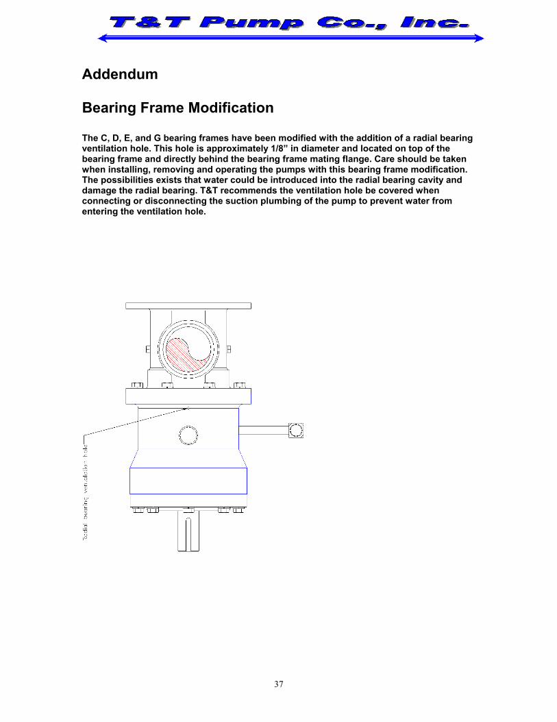
Addendum Bearing Frame Modification The C, D, E, and G bearing frames have been modified with the addition of a radial bearing ventilation hole. This hole is approximately 1/8” in diameter and located on top of the bearing frame and directly behind the bearing frame mating flange. Care should be taken when installing, removing and operating the pumps with this bearing frame modification. The possibilities exists that water could be introduced into the radial bearing cavity and damage the radial bearing. T&T recommends the ventilation hole be covered when connecting or disconnecting the suction plumbing of the pump to prevent water from entering the ventilation hole.
37
![CLASS: IX ENGLISH I UNIT TEST I (JULY) TEXT BOOK: CONCISE PHYSICS PART I [STD IX] PUBLISHER: SELINA PUBLICATIONS UNIT TEST I [JULY] Chapters: 1. Current electricity. 2. Upthrust and](https://img.pdfslide.net/doc/110x75/5ae6e2837f8b9a8b2b8ddb85/class-ix-english-i-unit-test-i-july-text-book-concise-physics-part-i-std-ix.jpg)


![For more free educatioal stuffs, visit: (iv) (i) (ii) alkanes; alkenes; alkynes; alkanols. [4 marks] What is meant by the term upthrust? A balloon inflated with hydrogen gas rises](https://img.pdfslide.net/doc/110x75/5e981707f7faac0ed1417c00/for-more-free-educatioal-stuffs-visit-iv-i-ii-alkanes-alkenes-alkynes.jpg)