Embed Size (px)
Citation preview
BEASTTHE
Tube and PipeNotcher
OperatingInstructions
J D SQUARED INC.www.jd2.com
PATENT PENDING
Copyright (c) 2007
Notches In BendsStraight Notches
Angled Notches
Offset Notches
Swivel Mount
Mounting Surface
STEP 1
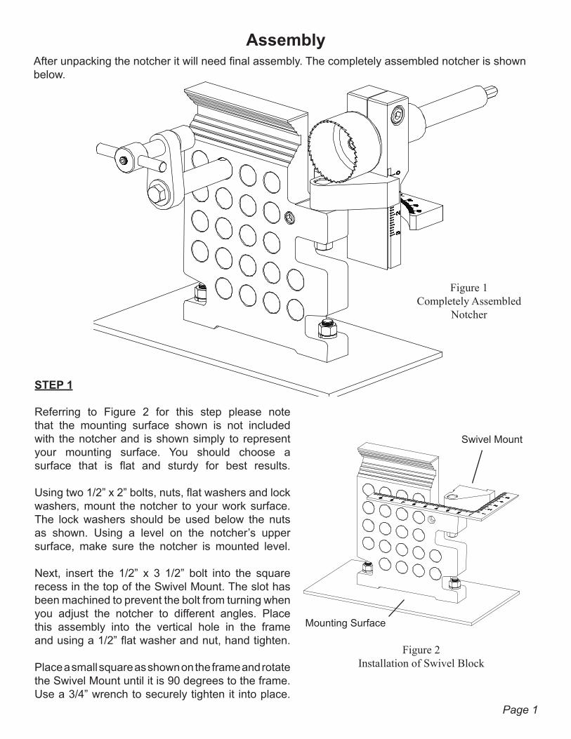
Referring to Figure 2 for this step please note that the mounting surface shown is not included with the notcher and is shown simply to represent your mounting surface. You should choose a surface that is flat and sturdy for best results.
Using two 1/2” x 2” bolts, nuts, flat washers and lock washers, mount the notcher to your work surface. The lock washers should be used below the nuts as shown. Using a level on the notcher’s upper surface, make sure the notcher is mounted level.
Next, insert the 1/2” x 3 1/2” bolt into the square recess in the top of the Swivel Mount. The slot has been machined to prevent the bolt from turning when you adjust the notcher to different angles. Place this assembly into the vertical hole in the frame and using a 1/2” flat washer and nut, hand tighten.
Place a small square as shown on the frame and rotate the Swivel Mount until it is 90 degrees to the frame. Use a 3/4” wrench to securely tighten it into place.
After unpacking the notcher it will need final assembly. The completely assembled notcher is shown below.
Figure 1Completely Assembled
Notcher
Figure 2Installation of Swivel Block
Assembly
Page 1
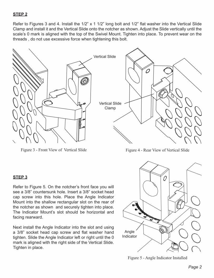
STEP 2
Refer to Figures 3 and 4. Install the 1/2” x 1 1/2” long bolt and 1/2” flat washer into the Vertical Slide Clamp and install it and the Vertical Slide onto the notcher as shown. Adjust the Slide vertically until the scale’s 0 mark is aligned with the top of the Swivel Mount. Tighten into place. To prevent wear on the threads , do not use excessive force when tightening this bolt.
Figure 3 - Front View of Vertical Slide Figure 4 - Rear View of Vertical Slide
Vertical Slide Clamp
Vertical Slide
STEP 3
Refer to Figure 5. On the notcher’s front face you will see a 3/8” countersunk hole. Insert a 3/8” socket head cap screw into this hole. Place the Angle Indicator Mount into the shallow rectangular slot on the rear of the notcher as shown and securely tighten into place. The Indicator Mount’s slot should be horizontal and facing rearward.
Next install the Angle Indicator into the slot and using a 3/8” socket head cap screw and flat washer hand tighten. Slide the Angle Indicator left or right until the 0 mark is aligned with the right side of the Vertical Slide. Tighten in place.
Figure 5 - Angle Indicator Installed
AngleIndicator
Page 2
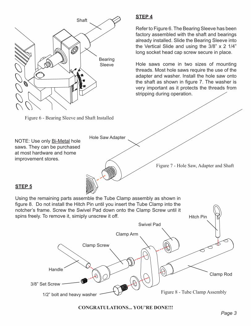
Figure 6 - Bearing Sleeve and Shaft Installed
BearingSleeve
ShaftSTEP 4
Refer to Figure 6. The Bearing Sleeve has been factory assembled with the shaft and bearings already installed. Slide the Bearing Sleeve into the Vertical Slide and using the 3/8” x 2 1/4” long socket head cap screw secure in place.
Hole saws come in two sizes of mounting threads. Most hole saws require the use of the adapter and washer. Install the hole saw onto the shaft as shown in figure 7. The washer is very important as it protects the threads from stripping during operation.
Figure 7 - Hole Saw, Adapter and Shaft
Hole Saw AdapterNOTE: Use only Bi-Metal hole saws. They can be purchased at most hardware and home improvement stores.
Figure 8 - Tube Clamp Assembly
STEP 5
Using the remaining parts assemble the Tube Clamp assembly as shown in figure 8. Do not install the Hitch Pin until you insert the Tube Clamp into the notcher’s frame. Screw the Swivel Pad down onto the Clamp Screw until it spins freely. To remove it, simiply unscrew it off.
Clamp Screw
Swivel Pad
Hitch Pin
Handle
3/8” Set Screw
Clamp Arm
1/2” bolt and heavy washer
CONGRATULATIONS... YOU’RE DONE!!!
Clamp Rod
Page 3
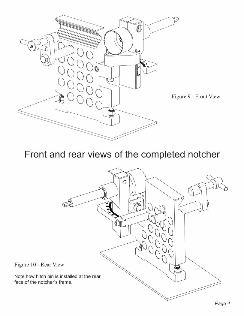
Front and rear views of the completed notcher
Note how hitch pin is installed at the rear face of the notcher’s frame.
Figure 9 - Front View
Figure 10 - Rear View
Page 4
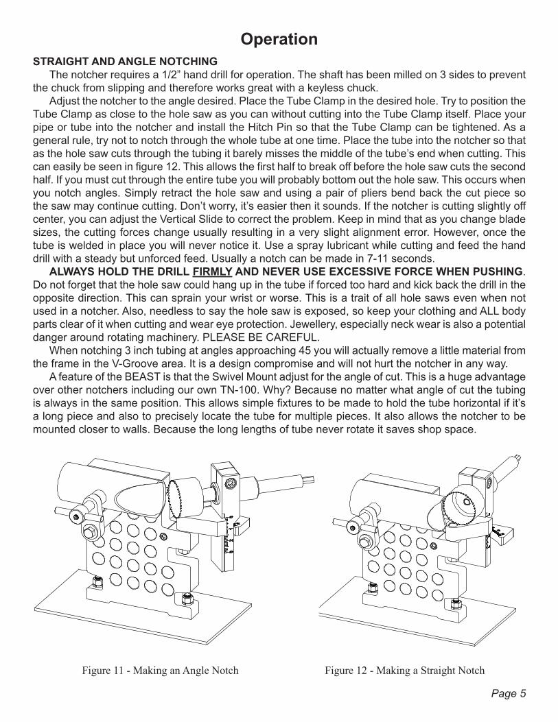
OperationSTRAIGHT AND ANGLE NOTCHING
The notcher requires a 1/2” hand drill for operation. The shaft has been milled on 3 sides to prevent the chuck from slipping and therefore works great with a keyless chuck.
Adjust the notcher to the angle desired. Place the Tube Clamp in the desired hole. Try to position the Tube Clamp as close to the hole saw as you can without cutting into the Tube Clamp itself. Place your pipe or tube into the notcher and install the Hitch Pin so that the Tube Clamp can be tightened. As a general rule, try not to notch through the whole tube at one time. Place the tube into the notcher so that as the hole saw cuts through the tubing it barely misses the middle of the tube’s end when cutting. This can easily be seen in figure 12. This allows the first half to break off before the hole saw cuts the second half. If you must cut through the entire tube you will probably bottom out the hole saw. This occurs when you notch angles. Simply retract the hole saw and using a pair of pliers bend back the cut piece so the saw may continue cutting. Don’t worry, it’s easier then it sounds. If the notcher is cutting slightly off center, you can adjust the Vertical Slide to correct the problem. Keep in mind that as you change blade sizes, the cutting forces change usually resulting in a very slight alignment error. However, once the tube is welded in place you will never notice it. Use a spray lubricant while cutting and feed the hand drill with a steady but unforced feed. Usually a notch can be made in 7-11 seconds.
ALWAYS HOLD THE DRILL FIRMLY AND NEVER USE EXCESSIVE FORCE WHEN PUSHING. Do not forget that the hole saw could hang up in the tube if forced too hard and kick back the drill in the opposite direction. This can sprain your wrist or worse. This is a trait of all hole saws even when not used in a notcher. Also, needless to say the hole saw is exposed, so keep your clothing and ALL body parts clear of it when cutting and wear eye protection. Jewellery, especially neck wear is also a potential danger around rotating machinery. PLEASE BE CAREFUL.
When notching 3 inch tubing at angles approaching 45 you will actually remove a little material from the frame in the V-Groove area. It is a design compromise and will not hurt the notcher in any way.
A feature of the BEAST is that the Swivel Mount adjust for the angle of cut. This is a huge advantage over other notchers including our own TN-100. Why? Because no matter what angle of cut the tubing is always in the same position. This allows simple fixtures to be made to hold the tube horizontal if it’s a long piece and also to precisely locate the tube for multiple pieces. It also allows the notcher to be mounted closer to walls. Because the long lengths of tube never rotate it saves shop space.
Figure 12 - Making a Straight NotchFigure 11 - Making an Angle Notch
Page 5
J D Squared Inc. 2244 Eddie Williams Rd., Johnson City, TN 37601 USA
(423) 979-0309 FAX (423) 979-2426www.jd2.com
If you have any questions please call or visit our web site at www.jd2.com and navigate to the BEAST Notcher page. There you can find further help in the way of photos and videos. Thank you very much for your business and good luck with your future projects.
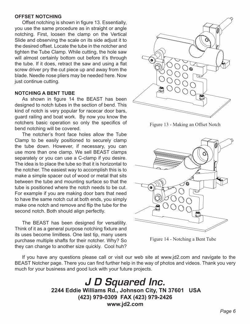
OFFSET NOTCHINGOffset notching is shown in figure 13. Essentially,
you use the same procedure as in straight or angle notching. First, loosen the clamp on the Vertical Slide and observing the scale on its side adjust it to the desired offset. Locate the tube in the notcher and tighten the Tube Clamp. While cutting, the hole saw will almost certainly bottom out before it’s through the tube. If it does, retract the saw and using a flat screw driver pry the cut piece up and away from the blade. Needle nose pliers may be needed here. Now just continue cutting.
NOTCHING A BENT TUBEAs shown in figure 14 the BEAST has been
designed to notch tubes in the section of bend. This kind of notch is very popular for racecar door bars, guard railing and boat work. By now you know the notchers basic operation so only the specifics of bend notching will be covered.
The notcher’s front face holes allow the Tube Clamp to be easily positioned to securely clamp the tube down. However, if necessary, you can use more than one clamp. We sell BEAST clamps separately or you can use a C-clamp if you desire. The idea is to place the tube so that it is horizontal to the notcher. The easiest way to accomplish this is to make a simple spacer out of wood or metal that sits between the tube and mounting surface so that the tube is positioned where the notch needs to be cut. For example if you are making door bars that need to have the same notch cut at both ends, you simply make one notch and remove and flip the tube for the second notch. Both should align perfectly.
The BEAST has been designed for versatility.Think of it as a general purpose notching fixture and its uses become limitless. One last tip, many users purchase multiple shafts for their notcher. Why? So they can change to another size quickly. Cool huh?
Figure 13 - Making an Offset Notch
Figure 14 - Notching a Bent Tube
Page 6