Embed Size (px)
Citation preview

Wide range of micron-precision 3D measurements of tube interiors and exteriors
3-dimensional geometry (GD&T) of inside and outside surfaces
Chatter measurement
Roughness measurement
Defect detection - porosities, cracks, scratches
Thickness measurement of semi-transparent material coatings
Fully configurable automated inspection Easily integrated in fully-automated inspection setups
Inside diameter measurement Outside diameter measurement
Optical fiber to system interferometer
TubeInspect For non-contact 3D metrology of tube ID and OD
Measurement with non-contact side-looking probe
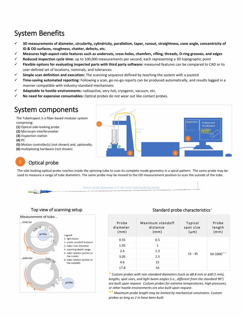
System Benefits 3D measurements of diameter, circularity, cylindricity, parallelism, taper, runout, straightness, cone angle, concentricity of
ID & OD surfaces, roughness, chatter, defects, etc.
Measures high-aspect-ratio features such as undercuts, cross-holes, chamfers, rifling, threads, O-ring grooves, and edges
Reduced inspection cycle time: up to 100,000 measurements per second, each representing a 3D topographic point
Flexible options for evaluating inspected parts with third party software: measured features can be compared to CAD or to
user-defined set of locations, nominals, and tolerances
Simple scan definition and execution: The scanning sequence defined by teaching the system with a joystick
Time-saving automated reporting: Following a scan, go-no-go reports can be produced automatically, and results logged in a
manner compatible with industry-standard mechanisms
Adaptable to hostile environments: radioactive, very hot, cryogenic, vacuum, etc.
No need for expensive consumables: Optical probes do not wear out like contact probes.
System components
Optical probe
The side-looking optical probe reaches inside the spinning tube to scan its complete inside geometry in a spiral pattern. The same probe may be used to measure a range of tube diameters. The same probe may be moved to the OD measurement position to scan the outside of the tube.
P r o be d i a m e te r
(m m )
M a x im um s ta n do f f d i s ta nce
(m m )
T y p i ca l s po t s i ze
( µm )
P r o be l e ng t h (m m )
0.55 0.5
15 - 35 50-1000**
1.05 1
2.4 1.3
3.05 2.5
4.6 15
17.8 54
* Custom probes with non-standard diameters (such as ø8.8 mm or ø30.5 mm),
lengths, spot sizes, and light beam angles (i.e., different from the standard 90°)are built upon request. Custom probes for extreme temperatures, high pressures,or other hostile environments are also built upon request.
** Maximum probe length may be limited by mechanical constraints. Custom
probes as long as 2 m have been built.
Extra-small-diameter (⌀1.05 mm) side-looking probe
The TubeInspect is a fiber-based modular system comprising: (1) Optical side-looking probe (2) Microcam interferometer(3) Inspection station(4) PC(5) Motion controller(s) (not shown) and, optionally,(6) multiplexing hardware (not shown)
1
Top view of scanning setup Standard probe characteristics*
Microcam interferometer The interferometer provides the light source to the optical probe and processes the optical signal received from the probe. The probe and the interferometer are connected with an optical fiber.
Microcam interferometer models
Microcam-3D Microcam-4D
General characteristics
Technology low-coherence interferometry
Light wavelength 1310 nm, infrared
Interferometer enclosure 4U rackable enclosure
445 (W) x 445 (L) x 178 (H) mm
Non-contact measurements
Scanning depth range options* 3.5 mm 7 mm 5 mm
Acquisition (A-scan) rate 2.10 kHz 1.05 kHz 100 kHz
Axial (Z-axis) resolution < 0.5 µm
Light spot size (Lateral [XY-axis] resolution) 4.1 - 146 µm, typically 15 - 35 µm
Standoff distance 0.5 - 100 mm for standard probes, up to 1 m for non-standard probes
Repeatability < 1 µm < 2 µm
Thickness measurements
Thickness measurement range (optical in air) 10 µm - 3.5 mm 10 µm - 7 mm 20 µm - 5 mm
Typical materials for thickness measurements glass, polymers, multi-layer films, coatings, plastics, silicone, liquids, specular or non-specular
Sample reflectivity 0.1 - 100%
* To further increase maximum scanning depth, a mechanical displacement axis is available.
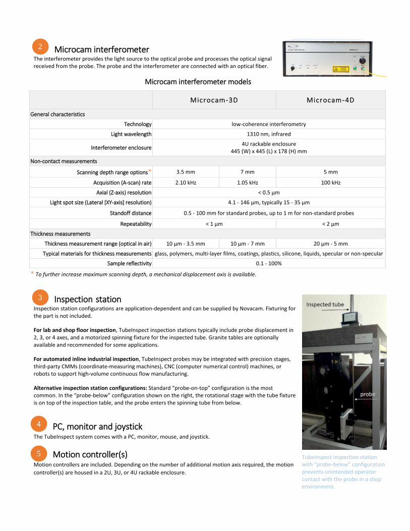
Inspection station Inspection station configurations are application-dependent and can be supplied by Novacam. Fixturing for the part is not included.
For lab and shop floor inspection, TubeInspect inspection stations typically include probe displacement in 2, 3, or 4 axes, and a motorized spinning fixture for the inspected tube. Granite tables are optionally available and recommended for some applications.
For automated inline industrial inspection, TubeInspect probes may be integrated with precision stages, third-party CMMs (coordinate-measuring machines), CNC (computer numerical control) machines, or robots to support high-volume continuous flow manufacturing.
Alternative inspection station configurations: Standard “probe-on-top” configuration is the most common. In the “probe-below” configuration shown on the right, the rotational stage with the tube fixture is on top of the inspection table, and the probe enters the spinning tube from below.
PC, monitor and joystick The TubeInspect system comes with a PC, monitor, mouse, and joystick.
Motion controller(s) Motion controllers are included. Depending on the number of additional motion axis required, the motion
controller(s) are housed in a 2U, 3U, or 4U rackable enclosure.
2
3
4
TubeInspect inspection station with “probe-below” configuration prevents unintended operator contact with the probe in a shop environment.
5

Hardware for multiplexing support (optional) Optical switches are available for multiplexing up to 8 probes to a single Microcam interferometer. Multiplexed probes may be used one at a time. This option brings additional return on investment (ROI) to many installations.
System software The TubeInspect comes with Novacam high-performance data acquisition software, which is PC, Windows®-based, and user-friendly for scan programming. The TubeInspect simultaneously generates 3 data sets from the same scan: 3D point cloud, light intensity image, and height image. The height and light intensity images facilitate defect detection. STL file format is also available.
An application programming interface (API) is available for system integrators and OEMs to accommodate a wide variety of online and offline applications. Exported results may be integrated with data loggers and SPC software.
A turnkey solution for full GD&T analysis of measured parts is available with Innovmetric’s PolyWorks InspectorTM metrology software that may be purchased with the system. Go-no-go reporting is easily programmed and automated. Operators benefit from capabilities such as a quick visual comparison (deviation map) of the acquired part measurements to pre-specified tolerances or to the CAD of the part.
Visualizing the scan data may be accomplished by importing the data into third party visualization and numerical analysis software such as PolyWorks Inspector, Geomagic, ImageJ, SolidWorks, Octave, MatLab, Mathematica, IDL, or IGOR Pro.
Deriving application-specific measurements from the 3D point cloud is available through a selection of in-house and third party software. Novacam supports the following options:
Standard system configuration Microcam-3D interferometer
1 standard 4.6 mm-diameter side-looking probe (for inspection of bores up to 300 mm (12″) deep)
3-axis inspection station and 3-axis motion controller
1 chuck with motor and motion controller for rotating the inspected tube
PC with Novacam acquisition software
1 year warranty
Instrument safety TubeInspect systems feature an in-probe red laser
pointer (650 nm wavelength) for alignment purposes.
They systems are Class 1M Laser products, with < 20
mW of infrared and < 5 mW of in-probe laser pointer.
Novacam in-house software 3rd party software, such as
Dimensional measurements (GD&T
parameters) PolyWorks Inspector (turnkey solution), Geomagic
Roughness and surface analysis TrueSurf, MountainsMap
Thickness
Chatter (vibration)
Volume loss
Defects Custom-developed*
* Novacam offers the option of custom data processing, reporting, and defect detection programs that can be written based
on client requirements.
6
Novacam Technologies Inc. 277 Lakeshore Road, Suite #04 Pointe-Claire, Quebec, H9S 4L2, Canada
PT Bersinar Gemilang SuksesGedung Pembina Graha Block II R. 125Jalan DI. Panjaitan No. 45Jakarta 13350 ([email protected])
© 2019 Novacam Technologies Inc. All rights reserved. Document: PS-TUBEINSPECT-1.0.1 (2019-07-09)
Fuel feed hole
ID of fuel injector nozzle (ID ø4.04 mm), 3D point cloud viewed with PolyWorks InspectorTM
Data processing options