Embed Size (px)
Citation preview

Mothe
rboa
rdTUF B450-PLUS GAMING

ii
E14220First EditionMay 2018
Copyright © 2018 ASUSTeK COMPUTER INC. All Rights Reserved.No part of this manual, including the products and software described in it, may be reproduced, transmitted, transcribed, stored in a retrieval system, or translated into any language in any form or by any means, except documentation kept by the purchaser for backup purposes, without the express written permission of ASUSTeK COMPUTER INC. (“ASUS”).Product warranty or service will not be extended if: (1) the product is repaired, modified or altered, unless such repair, modification of alteration is authorized in writing by ASUS; or (2) the serial number of the product is defaced or missing.ASUS PROVIDES THIS MANUAL “AS IS” WITHOUT WARRANTY OF ANY KIND, EITHER EXPRESS OR IMPLIED, INCLUDING BUT NOT LIMITED TO THE IMPLIED WARRANTIES OR CONDITIONS OF MERCHANTABILITY OR FITNESS FOR A PARTICULAR PURPOSE. IN NO EVENT SHALL ASUS, ITS DIRECTORS, OFFICERS, EMPLOYEES OR AGENTS BE LIABLE FOR ANY INDIRECT, SPECIAL, INCIDENTAL, OR CONSEQUENTIAL DAMAGES (INCLUDING DAMAGES FOR LOSS OF PROFITS, LOSS OF BUSINESS, LOSS OF USE OR DATA, INTERRUPTION OF BUSINESS AND THE LIKE), EVEN IF ASUS HAS BEEN ADVISED OF THE POSSIBILITY OF SUCH DAMAGES ARISING FROM ANY DEFECT OR ERROR IN THIS MANUAL OR PRODUCT.SPECIFICATIONS AND INFORMATION CONTAINED IN THIS MANUAL ARE FURNISHED FOR INFORMATIONAL USE ONLY, AND ARE SUBJECT TO CHANGE AT ANY TIME WITHOUT NOTICE, AND SHOULD NOT BE CONSTRUED AS A COMMITMENT BY ASUS. ASUS ASSUMES NO RESPONSIBILITY OR LIABILITY FOR ANY ERRORS OR INACCURACIES THAT MAY APPEAR IN THIS MANUAL, INCLUDING THE PRODUCTS AND SOFTWARE DESCRIBED IN IT.Products and corporate names appearing in this manual may or may not be registered trademarks or copyrights of their respective companies, and are used only for identification or explanation and to the owners’ benefit, without intent to infringe.
Offer to Provide Source Code of Certain SoftwareThis product contains copyrighted software that is licensed under the General Public License (“GPL”), under the Lesser General Public License Version (“LGPL”) and/or other Free Open Source Software Licenses. Such software in this product is distributed without any warranty to the extent permitted by the applicable law. Copies of these licenses are included in this product.Where the applicable license entitles you to the source code of such software and/or other additional data, you may obtain it for a period of three years after our last shipment of the product, either(1) for free by downloading it from http://support.asus.com/downloador(2) for the cost of reproduction and shipment, which is dependent on the preferred carrier and the location where you want to have it shipped to, by sending a request to:
ASUSTeK Computer Inc.Legal Compliance Dept.15 Li Te Rd.,Beitou, Taipei 112Taiwan
In your request please provide the name, model number and version, as stated in the About Box of the product for which you wish to obtain the corresponding source code and your contact details so that we can coordinate the terms and cost of shipment with you.The source code will be distributed WITHOUT ANY WARRANTY and licensed under the same license as the corresponding binary/object code.This offer is valid to anyone in receipt of this information.ASUSTeK is eager to duly provide complete source code as required under various Free Open Source Software licenses. If however you encounter any problems in obtaining the full corresponding source code we would be much obliged if you give us a notification to the email address [email protected], stating the product and describing the problem (please DO NOT send large attachments such as source code archives, etc. to this email address).

iii
ContentsSafety information ...................................................................................... ivAbout this guide ......................................................................................... ivPackage contents ....................................................................................... viTUF B450-PLUS GAMING specifications summary ................................. vi
Chapter 1: Product introductionMotherboard overview ............................................................................. 1-1Central Processing Unit (CPU) ................................................................ 1-8System memory ...................................................................................... 1-10
Chapter 2: BIOS informationBIOS setup program ................................................................................. 2-1EZ Mode ..................................................................................................... 2-2Advanced Mode ........................................................................................ 2-3Exit menu ................................................................................................... 2-4
AppendixNotices .......................................................................................................A-1ASUS contact information .......................................................................A-5

iv
Safety informationElectrical safety• To prevent electrical shock hazard, disconnect the power cable from the electrical outlet
before relocating the system.
• When adding or removing devices to or from the system, ensure that the power cables for the devices are unplugged before the signal cables are connected. If possible, disconnect all power cables from the existing system before you add a device.
• Before connecting or removing signal cables from the motherboard, ensure that all power cables are unplugged.
• Seek professional assistance before using an adapter or extension cord. These devices could interrupt the grounding circuit.
• Ensure that your power supply is set to the correct voltage in your area. If you are not sure about the voltage of the electrical outlet you are using, contact your local power company.
• If the power supply is broken, do not try to fix it by yourself. Contact a qualified service technician or your retailer.
Operation safety• Before installing the motherboard and adding components, carefully read all the manuals
that came with the package.
• Before using the product, ensure all cables are correctly connected and the power cables are not damaged. If you detect any damage, contact your dealer immediately.
• To avoid short circuits, keep paper clips, screws, and staples away from connectors, slots, sockets and circuitry.
• Avoid dust, humidity, and temperature extremes. Do not place the product in any area where it may be exposed to moisture.
• Place the product on a stable surface.
• If you encounter technical problems with the product, contact a qualified service technician or your retailer.
About this guideThis user guide contains the information you need when installing and configuring the motherboard.
How this guide is organizedThis guide contains the following parts:
• Chapter 1: Product introductionThis chapter describes the features of the motherboard and the new technology it supports. It includes descriptions of the switches, jumpers, and connectors on the motherboard.
• Chapter 2: BIOS informationThis chapter discusses changing system settings through the BIOS Setup menus.

v
Where to find more informationRefer to the following sources for additional information and for product and software updates.
1. ASUS websitesThe ASUS website provides updated information on ASUS hardware and software products. Refer to the ASUS contact information.
2. Optional documentationYour product package may include optional documentation, such as warranty flyers, that may have been added by your dealer. These documents are not part of the standard package.
Conventions used in this guideTo ensure that you perform certain tasks properly, take note of the following symbols used throughout this manual.
DANGER/WARNING: Information to prevent injury to yourself when completing a task.
CAUTION: Information to prevent damage to the components when completing a task.
IMPORTANT: Instructions that you MUST follow to complete a task.
NOTE: Tips and additional information to help you complete a task.
TypographyBold text Indicates a menu or an item to select.
Italics Used to emphasize a word or a phrase.
<Key> Keys enclosed in the less-than and greater-than sign means that you must press the enclosed key.
Example: <Enter> means that you must press the Enter or Return key.
<Key1> + <Key2> + <Key3> If you must press two or more keys simultaneously, the key names are linked with a plus sign (+).

vi
TUF B450-PLUS GAMING specifications summary
(continued on the next page)
Package contentsCheck your motherboard package for the following items.
Motherboard ASUS TUF B450-PLUS GAMING motherboard
Cables 2 x Serial ATA 6.0 Gb/s cables
Accessories
1 x I/O shield1 x M.2 screw package 1 x TUF Certification Card1 x TUF GAMING Sticker
Application DVD 1 x Support DVD
Documentation 1 x User Manual
If any of the above items is damaged or missing, contact your retailer.
CPU
AM4 socket for AMD Ryzen™ 2nd Generation / Ryzen™ with Radeon™ Vega Graphics / Ryzen™ 1st Generation processors
Supports CPU up to 8 cores** Due to CPU limitation, CPU cores supported vary by processor. ** Refer to www.asus.com for AMD CPU support list.
Chipset AMD B450 chipset
Memory
AMD Ryzen™ 2nd Generation/AMD Ryzen™ with Radeon™ Vega Graphics/ Ryzen™ 1st Generation processors:
4 x DIMM, max. 64GB, DDR4 3200(O.C.)/3000(O.C.)/2800(O.C)/2666/2400/2133 MHz, un-buffered memory
Dual-channel memory architecture* Refer to www.asus.com for the latest Memory QVL (Qualified Vendors List).** ECC memory(ECC mode) support varies by CPU.
Graphics
Integrated Graphics in the AMD Ryzen™ with Radeon™ Vega Graphics processors
Multi-VGA output support: HDMI and DVI-D ports- Supports HDMI 2.0b output with a maximum resolution of 4096x2160@60Hz- Supports DVI-D output with a maximum resolution of 1920 x 1200 @60Hz
Expansion slots
AMD Ryzen™ 2nd Generation / Ryzen™ 1st Generation processors:1 x PCI Express 3.0 x16 slot (max. @x16 mode)
AMD Ryzen™ with Radeon™ Vega Graphics processors:1 x PCI Express 3.0 x16 slot (max. @x8 mode)
AMD B450 Chipset:1 x PCI Express 2.0 x16 slot (max. @x4 mode)3 x PCI Express 2.0 x1 slots
USB
AMD Ryzen™ 2nd Generation/ Ryzen™ with Radeon™ Vega Graphics/ Ryzen™ 1st Generation processors:
- 3 x USB 3.1 Gen 1 (up to 5Gbps) ports (2 Type A ports and 1 Type C port at back panel)
AMD B450 Chipset:- 2 x USB 3.1 Gen 2 (up to 10 Gbps) ports ( 2 ports at back panel)- 2 x USB 3.1 Gen 1 (up to 5Gbps) ports ( 2 ports at mid-board)- 6 x USB 2.0/1.1 ports (2 ports at back panel, 4 ports at mid-board)

vii
TUF B450-PLUS GAMING specifications summary
(continued on the next page)
Multi-GPU support Supports AMD CrossFireX™ Technology
Storage
AMD B450 Chipset - 4 x Serial ATA 6.0 Gb/s connectors with RAID 0, RAID 1 and RAID 10 support
AMD Ryzen™ 2nd Generation/ Ryzen™ with Radeon™ Vega Graphics/ Ryzen™ 1st Generation processors:
- 2 x Serial ATA 6.0 Gb/s connectors with RAID 0, RAID 1 and RAID 10 support
AMD Ryzen™ 2nd Generation/ Ryzen™ with Radeon™ Vega Graphics/ Ryzen™ 1st Generation processors:
- 1 x M.2 socket 3 with M Key, Type 2242/2260/2280/22110 (PCIe 3.0 x4 and SATA modes) storage devices support*
* The M.2 Socket shares bandwidth with the SATA_5/6 ports, and therefore the SATA_5/6 ports cannot be used when an M.2 device is installed.
LAN Realtek® 8111H Gigabit LAN controller
Audio
Realtek® ALC 887-VD2 8-Channel High Definition Audio CODEC
- Exclusive DTS Custom for GAMING Headsets
- Audio Shielding: Ensures precision analog/digital separation and greatly reduces multi-lateral interference
- Dedicated audio PCB layers: Separate layers for left and right channels to guard the quality of the sensitive audio signals
- Premium Japanese audio capacitors: Provide warm, natural and immersive sound with exceptional clarity and fidelity
- Supports jack-detection and front panel jack-retasking
- Audio Cover: Effective shielding preserves the integrity of audio signals to ensure best quality
* Use a chassis with HD audio module in the front panel to support an 8-channel audio output.
ASUS unique features
Dependable Stability
ASUS TUF PROTECTION- ASUS SafeSlot: Protect your graphics card Investment- ASUS LANGuard: Protects against LAN surges, lightning strikes and static-
electricity discharges!- ASUS Overvoltage Protection: World-class circuit-protecting power design- ASUS Stainless-Steel Back I/O: 3X corrosion-resistance for greater durability!- ASUS DIGI+ VRM: 6 Phase digital power design
Superb performance
UEFI BIOS - The most advanced options with a fast response time
ASUS Fan Xpert 4 Core - Advanced fan and liquid controls for ultimate cooling and quietness
GAMING
Aura - Brings up your Build

viii
TUF B450-PLUS GAMNG specifications summary
ASUS unique features
ASUS Exclusive Features- ASUS AI Charger- ASUS File Transfer- ASUS AI Suite 3- ASUS PC Cleaner
Easy PC DIY
Safe motherboard mounting - Component-free areas to minimize damage risk Q-Design - ASUS Q-DIMM - ASUS Q-Slot
UEFI BIOS EZ Mode
- Featuring friendly graphics user interface - ASUS CrashFree BIOS 3 - ASUS EZ Flash 3
ASUS Quiet Thermal Solution
Quiet Thermal Design: - Stylish Fanless Design: MOS Heat-sink & Chipset Heat-sink solution - ASUS Fan Xpert 4 core
Rear panel I/O ports
1 x PS/2 Keyboard/Mouse combo port
1 x HDMI port
1 x DVI-D port
1 x LAN (RJ-45) port
2 x USB 3.1 Gen 2 (up to 10 Gbps) ports (Type A,teal blue)
1 x USB 3.1 Gen 1 (up to 5 Gbps) port (Type C)
2 x USB 3.1 Gen 1 (up to 5 Gbps) ports(Type A, blue)
2 x USB 2.0/1.1 ports
3 x Audio jacks support 8-channel audio output
Internal connectors
1 x USB 3.1 Gen 1 (up to 5Gbps) connector supports additional 2 USB 3.1 Gen 1 ports
2 x USB 2.0/1.1 connectors support additional 4 USB 2.0/1.1 ports
6 x SATA 6.0 Gb/s connectors
1 x M.2 socket 3 for M Key and type 2242/2260/2280/22110 devices support(both SATA & PCIe mode)
1 x COM connector
1 x CPU Fan connector
3 x 4-pin Chassis Fan connectors for both 3-pin(DC mode) and 4-pin(PWM mode) coolers control
1 x Front panel audio connector
1 x 24-pin EATX power connector
1 x 8-pin EATX 12V power connector
1 x 2-pin Clear CMOS header
1 x System panel connector
1 x S/PDIF out connector
1 x AIO pump header
1 x Aura RGB Strip header
(continued on the next page)

ix
Specifications are subject to change without notice.
BIOS features
128 Mb Flash ROM, UEFI AMI BIOS, PnP, SM BIOS 3.1, ACPI 6.1, Multi-language BIOS, ASUS EZ Flash 3, ASUS CrashFree BIOS 3, F3 My Favorite, Last Modified log, F12 PrintScreen,F4 AURA ON/OFF, F9 Search and ASUS DRAM SPD (Serial Presence Detect) memory information
Manageability WOL by PME, PXE
Support DVD
Drivers
ASUS Utilities
ASUS Update
Anti-virus software (OEM version)
OS support Windows® 10 (64-bit)
Form factor ATX form factor: 12” x 9.6” (30.5 cm x 24.4 cm)

ASUS TUF B450-PLUS GAMING1-1
Product introduction 1Motherboard overview
• Unplug the power cord from the wall socket before touching any component.
• Before handling components, use a grounded wrist strap or touch a safely grounded object or a metal object, such as the power supply case, to avoid damaging them due to static electricity.
• Before you install or remove any component, ensure that the ATX power supply is switched off or the power cord is detached from the power supply. Failure to do so may cause severe damage to the motherboard, peripherals, or components.
• Unplug the power cord before installing or removing the motherboard. Failure to do so can cause you physical injury and damage to motherboard components.
Place this side towards
the rear of the chassis
Scan the QR code to get the detailed pin definitions.
®
DD
R4
DIM
M_A
1 (6
4bit,
288
-pin
mod
ule)
DD
R4
DIM
M_A
2* (6
4bit,
288
-pin
mod
ule)
DD
R4
DIM
M_B
1 (6
4bit,
288
-pin
mod
ule)
DD
R4
DIM
M_B
2* (6
4bit,
288
-pin
mod
ule)
AIO
_PU
MP
CPU_FAN
CHA_FAN2
CHA_FAN3
CH
A_F
AN
1
CLRTCSPDIF_OUT
M.2
(SO
CK
ET3
)
PANEL
AAFP
COM
SA
TA6G
_6S
ATA
6G_5
EATX12V
EA
TXP
WR
U31G1_12
AMD®
B450
RTL8111H
U31G2_12
HDMI
U31G1_C5
SuperI/O
PCIEX1_1
PCIEX1_2
228022110 2260 2242
PCIEX1_3
PCIEX16_1
PCIEX16_2
USB56 USB34
LAN_U31G1_34
KBMS_USB12
DV
I
DIGI+VRM
24.4cm(9.6in)
30.5
cm(1
2in)
BATTERY
SO
CK
ET
AM
4
AUDIO
SATA6G_1SATA6G_2
SATA6G_3SATA6G_4
128MbBIOS
6
5
1
7
2
7
811121314
1 42 23
9 710
15
15
16
16
1-2Chapter 1: Product introduction
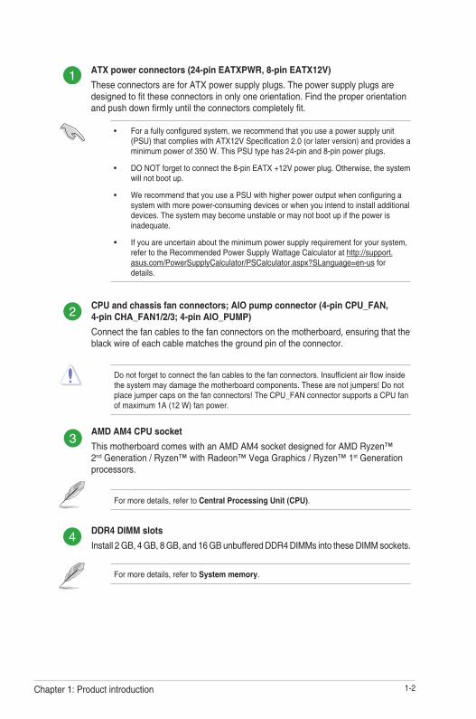
CPU and chassis fan connectors; AIO pump connector (4-pin CPU_FAN, 4-pin CHA_FAN1/2/3; 4-pin AIO_PUMP) Connect the fan cables to the fan connectors on the motherboard, ensuring that the black wire of each cable matches the ground pin of the connector.
Do not forget to connect the fan cables to the fan connectors. Insufficient air flow inside the system may damage the motherboard components. These are not jumpers! Do not place jumper caps on the fan connectors! The CPU_FAN connector supports a CPU fan of maximum 1A (12 W) fan power.
AMD AM4 CPU socketThis motherboard comes with an AMD AM4 socket designed for AMD Ryzen™ 2nd Generation / Ryzen™ with Radeon™ Vega Graphics / Ryzen™ 1st Generation processors.
For more details, refer to Central Processing Unit (CPU).
DDR4 DIMM slotsInstall 2 GB, 4 GB, 8 GB, and 16 GB unbuffered DDR4 DIMMs into these DIMM sockets.
For more details, refer to System memory.
ATX power connectors (24-pin EATXPWR, 8-pin EATX12V) These connectors are for ATX power supply plugs. The power supply plugs are designed to fit these connectors in only one orientation. Find the proper orientation and push down firmly until the connectors completely fit.
• For a fully configured system, we recommend that you use a power supply unit (PSU) that complies with ATX12V Specification 2.0 (or later version) and provides a minimum power of 350 W. This PSU type has 24-pin and 8-pin power plugs.
• DO NOT forget to connect the 8-pin EATX +12V power plug. Otherwise, the system will not boot up.
• We recommend that you use a PSU with higher power output when configuring a system with more power-consuming devices or when you intend to install additional devices. The system may become unstable or may not boot up if the power is inadequate.
• If you are uncertain about the minimum power supply requirement for your system, refer to the Recommended Power Supply Wattage Calculator at http://support.asus.com/PowerSupplyCalculator/PSCalculator.aspx?SLanguage=en-us for details.
ASUS TUF B450-PLUS GAMING1-3
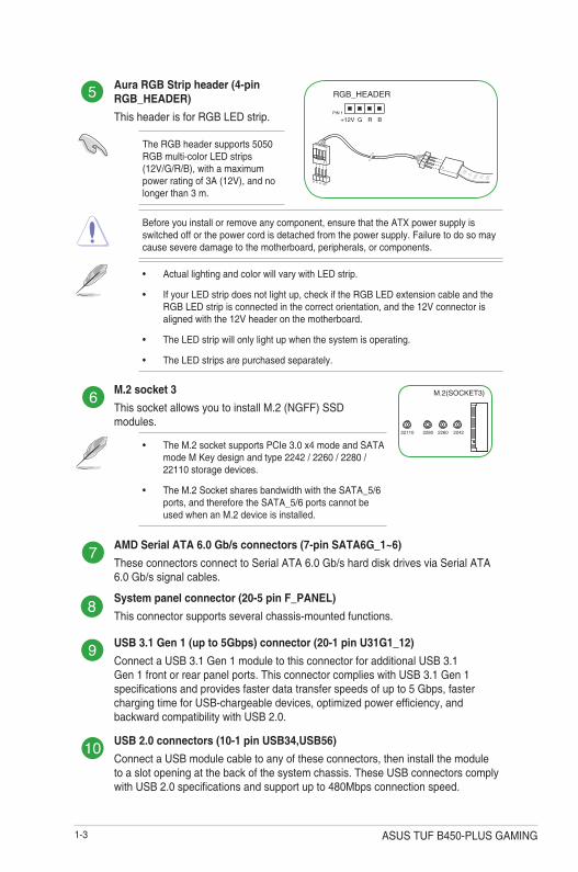
Aura RGB Strip header (4-pin RGB_HEADER) This header is for RGB LED strip.
12VGRB
RGB_HEADER
PIN 1
+12V G R B
The RGB header supports 5050 RGB multi-color LED strips (12V/G/R/B), with a maximum power rating of 3A (12V), and no longer than 3 m.
Before you install or remove any component, ensure that the ATX power supply is switched off or the power cord is detached from the power supply. Failure to do so may cause severe damage to the motherboard, peripherals, or components.
• Actual lighting and color will vary with LED strip.
• If your LED strip does not light up, check if the RGB LED extension cable and the RGB LED strip is connected in the correct orientation, and the 12V connector is aligned with the 12V header on the motherboard.
• The LED strip will only light up when the system is operating.
• The LED strips are purchased separately.
M.2 socket 3This socket allows you to install M.2 (NGFF) SSD modules.
M.2(SOCKET3)
228022110 2260 2242
• The M.2 socket supports PCIe 3.0 x4 mode and SATA mode M Key design and type 2242 / 2260 / 2280 / 22110 storage devices.
• The M.2 Socket shares bandwidth with the SATA_5/6 ports, and therefore the SATA_5/6 ports cannot be used when an M.2 device is installed.
AMD Serial ATA 6.0 Gb/s connectors (7-pin SATA6G_1~6)These connectors connect to Serial ATA 6.0 Gb/s hard disk drives via Serial ATA 6.0 Gb/s signal cables.
System panel connector (20-5 pin F_PANEL)This connector supports several chassis-mounted functions.
USB 3.1 Gen 1 (up to 5Gbps) connector (20-1 pin U31G1_12)Connect a USB 3.1 Gen 1 module to this connector for additional USB 3.1 Gen 1 front or rear panel ports. This connector complies with USB 3.1 Gen 1 specifications and provides faster data transfer speeds of up to 5 Gbps, faster charging time for USB-chargeable devices, optimized power efficiency, and backward compatibility with USB 2.0.
USB 2.0 connectors (10-1 pin USB34,USB56)Connect a USB module cable to any of these connectors, then install the module to a slot opening at the back of the system chassis. These USB connectors comply with USB 2.0 specifications and support up to 480Mbps connection speed.

1-4Chapter 1: Product introduction
Clear RTC RAM (2-pin CLRTC)This header allows you to clear the CMOS RTC RAM data of the system setup information such as date, time, and system passwords.
To erase the RTC RAM:
1. Turn OFF the computer and unplug the power cord.
2. Use a metal object such as a screwdriver to short the two pins.
3. Plug the power cord and turn ON the computer.
4. Hold down the <Del> key during the boot process and enter BIOS setup to re-enter data.
CLRTC
+3V
_BA
TG
ND
PIN 1
If the steps above do not help, remove the onboard battery and short the two pins again to clear the CMOS RTC RAM data. After clearing the CMOS, reinstall the battery.
Serial port connector (10-1 pin COM)This connector is for a serial (COM) port. Connect the serial port module cable to this connector, then install the module to a slot opening at the back of the system chassis.
Digital audio connector (4-1 pin SPDIF_OUT)This connector is for an additional Sony/Philips Digital Interface (S/PDIF) port. Connect the S/PDIF Out module cable to this connector, then install the module to a slot opening at the back of the system chassis.
SPDIF_OUT
+5V
SP
DIF
OU
TG
ND
PIN 1
Front panel audio connector (10-1 pin AAFP)This connector is for a chassis-mounted front panel audio I/O module that supports HD Audio standard. Connect one end of the front panel audio I/O module cable to this connector.
We recommend that you connect a high-definition front panel audio module to this connector to avail of the motherboard’s high-definition audio capability.
PCI Express 2.0 x1 slotsThis motherboard has three PCI Express 2.0 x1 slots that support PCI Express x1 network cards, SCSI cards, and other cards that comply with the PCI Express specifications.
PCI Express 3.0 / 2.0 x16 slotsThis motherboard supports two PCI Express 3.0 / 2.0 x16 graphic cards that comply with the PCI Express specifications.

ASUS TUF B450-PLUS GAMING1-5
VGA ConfigurationPCIe operating mode
PCIe 3.0 x16_1 PCIe 2.0 x16_2
Single VGA/PCIe card x16 N/A
Dual VGA/PCIe card x16 x4
• In single VGA card mode, use the PCIe 3.0/2.0 x16_1 slot (gray) for a PCI Express x16 graphics card to get better performance.
• We recommend that you provide sufficient power when running CrossFireX™ mode.
• Connect chassis fans to the motherboard chassis fan connectors when using multiple graphics cards for better thermal environment.
AMD Ryzen™ with Radeon™ Vega Graphics Processors
AMD Ryzen™ 2nd Generation/ Ryzen™ 1st Generation Processors
VGA ConfigurationPCIe operating mode
PCIe 3.0 x16_1 PCIe 2.0 x16_2
Single VGA/PCIe card x8 N/A
Dual VGA/PCIe card x8 x4

1-6Chapter 1: Product introduction
LAN port
Speed LED
Activity Link LED
Activity/Link LED Speed LEDStatus Description Status DescriptionOff No link OFF 10Mbps connectionOrange Linked ORANGE 100Mbps connectionOrange (Blinking)
Data activity GREEN 1Gbps connection
Orange (Blinking then steady)
Ready to wake up from S5 mode
1. PS/2 Keyboard/Mouse cambo port. This port is for a PS/2 keyboard or mouse.
2. DVI-D port. This port is for any DVI-D compatible device.
DVI-D can not be converted to output from RGB Signal to CRT and is not compatible with DVI-I.
4 5
68 7
2 3
9
1
11 10
Rear panel connectors
3. LAN (RJ-45) port. This port allows Gigabit connection to a Local Area Network (LAN) through a network hub.
LAN port LED indications
4. Line In port (light blue). This port connects to the tape, CD, DVD player, or other audio sources.
5. Line Out port (lime). This port connects to a headphone or a speaker. In the 4.1, 5.1and 7.1-channel configurations, the function of this port becomes Front Speaker Out.
6. Microphone port (pink). This port connects to a microphone.
Refer to the audio configuration table for the function of the audio ports in 2.1, 4.1, 5.1, or 7.1-channel configuration.

ASUS TUF B450-PLUS GAMING1-7
7. USB 3.1 Gen 1 (up to 5Gbps) ports. These two 9-pin Universal Serial Bus (USB) ports connect to USB 3.1 Gen 1 devices.
8. USB 3.1 Gen 2 (up to 10Gbps) ports. These 9-pin Universal Serial Bus (USB) ports are for USB 3.1 Gen 2 devices.
• USB 3.1 Gen 1/Gen 2 devices can only be used for data storage.
• Due to the design of AMD AM4 series chipset, all USB devices connected to the USB 2.0 and USB 3.1 Gen 1/Gen 2 ports are controlled by the xHCI controller.
• We strongly recommend that you connect USB 3.1 Gen 2 devices to USB 3.1 Gen 2 ports for faster and better performance from your USB 3.1 Gen 2 devices.
9. HDMI port. This port is for a High-Definition Multimedia Interface (HDMI) connector, and is HDCP compliant allowing playback of HD DVD, Blu-ray, and other protected content.
10. USB 3.1 Gen 1 (up to 5Gbps) port (Type-C). This Universal Serial Bus (USB) Type C port is for USB 3.1 Gen 1 mobile or peripheral devices.
11. USB 2.0 ports. These 4-pin Universal Serial Bus (USB) ports are for USB 2.0/1.1 devices.
Audio 2.1, 4.1, 5.1 or 7.1-channel configuration
Port Headset 2.1-channel 4.1-channel 5.1-channel 7.1-channel
Light Blue (Rear panel) Line In Rear Speaker Out Rear Speaker Out Rear Speaker OutLime (Rear panel) Line Out Front Speaker Out Front Speaker Out Front Speaker OutPink (Rear panel) Mic In Mic In Bass/Center Bass/Center
Lime (Front panel) - - - Side Speaker Out

1-8Chapter 1: Product introduction
Central Processing Unit (CPU)The motherboard comes with an AMD AM4 socket designed for AMD Ryzen™ 2nd Generation / Ryzen™ with Radeon™ Vega Graphics / Ryzen™ 1st Generation processors.
Unplug all power cables before installing the CPU.
The AM4 socket has a different pinout from the FM2+/FM2 socket. Ensure that you use a CPU designed for the AM4 socket. The CPU fits in only one correct orientation. DO NOT force the CPU into the socket to prevent bending the pins and damaging the CPU!
Installing the CPU
Apply the Thermal Interface Material to the CPU heatsink and CPU before you install the heatsink and fan if necessary.
1
3
2
4

ASUS TUF B450-PLUS GAMING1-9
Installing the CPU heatsink and fan assembly
Type 2
Type 1
Remove the screws and the retention module only. Do not remove the plate on the bottom.
1
1 2
2
3 4

1-10Chapter 1: Product introduction
System memoryOverviewThis motherboard comes with four Double Data Rate 4 (DDR4) Dual Inline Memory Module (DIMM) sockets. The figure illustrates the location of the DDR4 DIMM sockets:
• You may install varying memory sizes in Channel A and Channel B. The system maps the total size of the lower-sized channel for the dual-channel configuration. Any excess memory from the higher-sized channel is then mapped for single-channel operation.
• Always install DIMMs with the same CAS latency. For optimal compatibility, we recommend that you install memory modules of the same version or date code (D/C) from the same vendor. Check with the retailer to get the correct memory modules.
Recommended memory configuration
Channel SocketsChannel A DIMM_A1 & DIMM_A2*
Channel B DIMM_B1 & DIMM_B2*
• For system stability, use a more efficient memory cooling system to support a full memory load (4 DIMMs).
• Refer to www.asus.com for the latest Memory QVL (Qualified Vendors List)
DIMM_A2*
DIMM_B2*
DIMM_A2* DIMM_A2*
DIMM_B2*
DIMM_A1
DIMM_B1
DIMM_A1DIMM_A2*
DIMM_B1DIMM_B2*

ASUS TUF B450-PLUS GAMING1-11
Installing a DIMM
1 2
To remove a DIMM
BA
B
A
A

BIOS information 2• Scan the QR code to view the BIOS update guide.
• Before using the ASUS CrashFree BIOS 3 utility, rename the BIOS file in the removable device into TB450PSG.CAP.
BIOS setup programUse the BIOS Setup program to update the BIOS or configure its parameters. The BIOS screens include navigation keys and brief online help to guide you in using the BIOS Setup program.
Entering BIOS Setup at startupTo enter BIOS Setup at startup:Press <Delete> or <F2> during the Power-On Self Test (POST). If you do not press <Delete> or <F2>, POST continues with its routines.
Entering BIOS Setup after POSTTo enter BIOS Setup after POST:Press <Ctrl>+<Alt>+<Del> simultaneously.
Press the reset button on the system chassis.
Press the power button to turn the system off then back on. Do this option only if you failed to enter BIOS Setup using the first two options.
Using the power button, reset button, or the <Ctrl>+<Alt>+<Del> keys to force reset from a running operating system can cause damage to your data or system. We recommend you always shut down the system properly from the operating system.
• The BIOS setup screens shown in this section are for reference purposes only, and may not exactly match what you see on your screen.
• Visit the ASUS website at www.asus.com to download the latest BIOS file for this motherboard.
• If the system becomes unstable after changing any BIOS setting, load the default settings to ensure system compatibility and stability. Select the Load Optimized Defaults item under the Exit menu or press hotkey F5.
• If the system fails to boot after changing any BIOS setting, try to clear the CMOS and reset the motherboard to the default value. See section Motherboard overview for information on how to erase the RTC RAM.
BIOS menu screenThe BIOS setup program can be used under two modes: EZ Mode and Advanced Mode. Press <F7> to change between the two modes.
ASUS TUF B450-PLUS GAMING 2-1

EZ ModeBy default, the EZ Mode screen appears when you enter the BIOS setup program. The EZ Mode provides you an overview of the basic system information, and allows you to select the display language, system performance mode, fan profile and boot device priority. To access the Advanced Mode, click Advanced Mode(F7) or press <F7>.
The default screen for entering the BIOS setup program can be changed.
The boot device options vary depending on the devices you installed to the system.
Saves the changes and resets the
system
Displays the CPU/motherboard temperature, CPU voltage output, CPU/chassis fan speed, and SATA information
Displays the system properties of the selected mode. Click <Enter> to
switch EZ System Tuning modes
Displays the Advanced mode
menus
Selects the boot device priorityLoads optimized
default settings
Shows the bootable devicesDisplays the CPU Fan’s speed
Click the button to manually tune the fans
Search on FAQ
Turns the RGB LED lighting or functional LED on or off
Searches by BIOS item name, enter the item name to find the related item listing
Selects the display language of the BIOS setup program
2-2 Chapter 2: BIOS information

Configuration fields
Menu bar
General helpSub-menu items
Menu itemsScroll bar
Last modified settings
LanguageSearchMyFavorite Q-Fan control
Goes back to EZ Mode
Displays hardware monitoring data
Advanced ModeThe Advanced Mode provides advanced options for experienced end-users to configure the BIOS settings. The figure below shows an example of the Advanced Mode. Refer to the following sections for the detailed configurations.
To access the EZ Mode, click EzMode(F7) or press <F7>.
Popup window
Search on FAQHot Keys
AURA ON/OFF
ASUS TUF B450-PLUS GAMING 2-3

Load Optimized DefaultsThis option allows you to load the default values for each of the parameters on the Setup menus. When you select this option or if you press <F5>, a confirmation window appears. Select OK to load the default values.
Save Changes & ResetOnce you are finished making your selections, choose this option from the Exit menu to ensure the values you selected are saved. When you select this option or if you press <F10>, a confirmation window appears. Select OK to save changes and exit.
Discard Changes & ExitThis option allows you to exit the Setup program without saving your changes. When you select this option or if you press <Esc>, a confirmation window appears. Select OK to discard changes and exit.
Launch EFI Shell from USB drivesThis option allows you to attempt to launch the EFI Shell application (shellx64.efi) from one of the available USB devices.
Exit menuThe Exit menu items allow you to load the optimal default values for the BIOS items, and save or discard your changes to the BIOS items.
Search on FAQMove your mouse over this button to show a QR code. Scan this QR code with your mobile device to connect to the ASUS BIOS FAQ web page. You can also scan the QR code below.
2-4 Chapter 2: BIOS information

ASUS TUF B450-PLUS GAMING A-1
Appendix
NoticesFederal Communications Commission StatementThis device complies with Part 15 of the FCC Rules. Operation is subject to the following two conditions:
• This device may not cause harmful interference.
• This device must accept any interference received including interference that may cause undesired operation.
This equipment has been tested and found to comply with the limits for a Class B digital device, pursuant to Part 15 of the FCC Rules. These limits are designed to provide reasonable protection against harmful interference in a residential installation. This equipment generates, uses and can radiate radio frequency energy and, if not installed and used in accordance with manufacturer’s instructions, may cause harmful interference to radio communications. However, there is no guarantee that interference will not occur in a particular installation. If this equipment does cause harmful interference to radio or television reception, which can be determined by turning the equipment off and on, the user is encouraged to try to correct the interference by one or more of the following measures:
• Reorient or relocate the receiving antenna.
• Increase the separation between the equipment and receiver.
• Connect the equipment to an outlet on a circuit different from that to which the receiver is connected.
• Consult the dealer or an experienced radio/TV technician for help.
The use of shielded cables for connection of the monitor to the graphics card is required to assure compliance with FCC regulations. Changes or modifications to this unit not expressly approved by the party responsible for compliance could void the user’s authority to operate this equipment.

A-2 Appendix
Compliance Statement of Innovation, Science and Economic Development Canada (ISED)This device complies with Innovation, Science and Economic Development Canada licence exempt RSS standard(s). Operation is subject to the following two conditions: (1) this device may not cause interference, and (2) this device must accept any interference, including interference that may cause undesired operation of the device.
CAN ICES-3(B)/NMB-3(B)
Déclaration de conformité de Innovation, Sciences et Développement économique Canada (ISED)Le présent appareil est conforme aux CNR d’Innovation, Sciences et Développement économique Canada applicables aux appareils radio exempts de licence. L’exploitation est autorisée aux deux conditions suivantes : (1) l’appareil ne doit pas produire de brouillage, et (2) l’utilisateur de l’appareil doit accepter tout brouillage radioélectrique subi, même si le brouillage est susceptible d’en compromettre le fonctionnement.
CAN ICES-3(B)/NMB-3(B)
VCCI: Japan Compliance Statement
Class B ITE
KC: Korea Warning Statement

ASUS TUF B450-PLUS GAMING A-3
REACHComplying with the REACH (Registration, Evaluation, Authorisation, and Restriction of Chemicals) regulatory framework, we published the chemical substances in our products at ASUS REACH website at http://csr.asus.com/english/REACH.htm.
DO NOT throw the motherboard in municipal waste. This product has been designed to enable proper reuse of parts and recycling. This symbol of the crossed out wheeled bin indicates that the product (electrical and electronic equipment) should not be placed in municipal waste. Check local regulations for disposal of electronic products.
DO NOT throw the mercury-containing button cell battery in municipal waste. This symbol of the crossed out wheeled bin indicates that the battery should not be placed in municipal waste.
ASUS Recycling/Takeback ServicesASUS recycling and takeback programs come from our commitment to the highest standards for protecting our environment. We believe in providing solutions for you to be able to responsibly recycle our products, batteries, other components as well as the packaging materials. Please go to http://csr.asus.com/english/Takeback.htm for detailed recycling information in different regions.
Regional notice for California
WARNING
Cancer and Reproductive Harm - www.P65Warnings.ca.gov
Google™ License TermsCopyright© 2018 Google Inc. All Rights Reserved.Licensed under the Apache License, Version 2.0 (the “License”); you may not use this file except in compliance with the License. You may obtain a copy of the License at:
http://www.apache.org/licenses/LICENSE-2.0
Unless required by applicable law or agreed to in writing, software distributed under the License is distributed on an “AS IS” BASIS, WITHOUT WARRANTIES OR CONDITIONS OF ANY KIND, either express or implied.
See the License for the specific language governing permissions and limitations under the License.

A-4 Appendix
Română ASUSTeK Computer Inc. declară că acest dispozitiv se conformează cerinţelor esenţiale şi altor prevederi relevante ale directivelor conexe. Textul complet al declaraţiei de conformitate a Uniunii Europene se găseşte la: www.asus.com/supportSrpski ASUSTeK Computer Inc. ovim izjavljuje da je ovaj uređaj u saglasnosti sa osnovnim zahtevima i drugim relevantnim odredbama povezanih Direktiva. Pun tekst EU deklaracije o usaglašenosti je dostupan da adresi: www.asus.com/supportSlovensky Spoločnosť ASUSTeK Computer Inc. týmto vyhlasuje, že toto zariadenie vyhovuje základným požiadavkám a ostatým príslušným ustanoveniam príslušných smerníc. Celý text vyhlásenia o zhode pre štáty EÚ je dostupný na adrese: www.asus.com/supportSlovenščina ASUSTeK Computer Inc. izjavlja, da je ta naprava skladna z bistvenimi zahtevami in drugimi ustreznimi določbami povezanih direktiv. Celotno besedilo EU-izjave o skladnosti je na voljo na spletnem mestu: www.asus.com/supportEspañol Por la presente, ASUSTeK Computer Inc. declara que este dispositivo cumple los requisitos básicos y otras disposiciones pertinentes de las directivas relacionadas. El texto completo de la declaración de la UE de conformidad está disponible en: www.asus.com/supportSvenska ASUSTeK Computer Inc. förklarar härmed att denna enhet överensstämmer med de grundläggande kraven och andra relevanta föreskrifter i relaterade direktiv. Fulltext av EU-försäkran om överensstämmelse finns på: www.asus.com/supportУкраїнська ASUSTeK Computer Inc. заявляє, що цей пристрій відповідає основним вимогам та іншим відповідним положенням відповідних Директив. Повний текст декларації відповідності стандартам ЄС доступний на: www.asus.com/supportTürkçe AsusTek Computer Inc., bu aygıtın temel gereksinimlerle ve ilişkili Yönergelerin diğer ilgili koşullarıyla uyumlu olduğunu beyan eder. AB uygunluk bildiriminin tam metni şu adreste bulunabilir: www.asus.com/supportBosanski ASUSTeK Computer Inc. ovim izjavljuje da je ovaj uređaj usklađen sa bitnim zahtjevima i ostalim odgovarajućim odredbama vezanih direktiva. Cijeli tekst EU izjave o usklađenosti dostupan je na: www.asus.com/support
English ASUSTeK Computer Inc. hereby declares that this device is in compliance with the essential requirements and other relevant provisions of related Directives. Full text of EU declaration of conformity is available at: www.asus.com/supportFrançais AsusTek Computer Inc. déclare par la présente que cet appareil est conforme aux critères essentiels et autres clauses pertinentes des directives concernées. La déclaration de conformité de l’UE peut être téléchargée à partir du site Internet suivant : www.asus.com/supportDeutsch ASUSTeK Computer Inc. erklärt hiermit, dass dieses Gerät mit den wesentlichen Anforderungen und anderen relevanten Bestimmungen der zugehörigen Richtlinien übereinstimmt. Der gesamte Text der EU-Konformitätserklärung ist verfügbar unter: www.asus.com/supportItaliano ASUSTeK Computer Inc. con la presente dichiara che questo dispositivo è conforme ai requisiti essenziali e alle altre disposizioni pertinenti con le direttive correlate. Il testo completo della dichiarazione di conformità UE è disponibile all’indirizzo: www.asus.com/supportРусский Компания ASUS заявляет, что это устройство соответствует основным требованиям и другим соответствующим условиям соответствующих директив. Подробную информацию, пожалуйста, смотрите на www.asus.com/supportБългарски С настоящото ASUSTeK Computer Inc. декларира, че това устройство е в съответствие със съществените изисквания и другите приложими постановления на свързаните директиви. Пълният текст на декларацията за съответствие на ЕС е достъпна на адрес: www.asus.com/supportHrvatski ASUSTeK Computer Inc. ovim izjavljuje da je ovaj uređaj sukladan s bitnim zahtjevima i ostalim odgovarajućim odredbama vezanih direktiva. Cijeli tekst EU izjave o sukladnosti dostupan je na: www.asus.com/supportČeština Společnost ASUSTeK Computer Inc. tímto prohlašuje, že toto zařízení splňuje základní požadavky a další příslušná ustanovení souvisejících směrnic. Plné znění prohlášení o shodě EU je k dispozici na adrese: www.asus.com/supportDansk ASUSTeK Computer Inc. erklærer hermed, at denne enhed er i overensstemmelse med hovedkravene og andre relevante bestemmelser i de relaterede direktiver. Hele EU-overensstemmelseserklæringen kan findes på: www.asus.com/supportNederlands ASUSTeK Computer Inc. verklaart hierbij dat dit apparaat voldoet aan de essentiële vereisten en andere relevante bepalingen van de verwante richtlijnen. De volledige tekst van de EU-verklaring van conformiteit is beschikbaar op: www.asus.com/supportEesti Käesolevaga kinnitab ASUSTeK Computer Inc, et see seade vastab asjakohaste direktiivide oluliste nõuetele ja teistele asjassepuutuvatele sätetele. EL vastavusdeklaratsiooni täielik tekst on saadaval järgmisel aadressil: www.asus.com/supportSuomi ASUSTeK Computer Inc. ilmoittaa täten, että tämä laite on asiaankuuluvien direktiivien olennaisten vaatimusten ja muiden tätä koskevien säädösten mukainen. EU-yhdenmukaisuusilmoituksen koko teksti on luettavissa osoitteessa: www.asus.com/supportΕλληνικά Με το παρόν, η AsusTek Computer Inc. δηλώνει ότι αυτή η συσκευή συμμορφώνεται με τις θεμελιώδεις απαιτήσεις και άλλες σχετικές διατάξεις των Οδηγιών της ΕΕ. Το πλήρες κείμενο της δήλωσης συμβατότητας είναι διαθέσιμο στη διεύθυνση: www.asus.com/supportMagyar Az ASUSTeK Computer Inc. ezennel kijelenti, hogy ez az eszköz megfelel a kapcsolódó Irányelvek lényeges követelményeinek és egyéb vonatkozó rendelkezéseinek. Az EU megfelelőségi nyilatkozat teljes szövege innen letölthető: www.asus.com/supportLatviski ASUSTeK Computer Inc. ar šo paziņo, ka šī ierīce atbilst saistīto Direktīvu būtiskajām prasībām un citiem citiem saistošajiem nosacījumiem. Pilns ES atbilstības paziņojuma teksts pieejams šeit: www.asus.com/supportLietuvių „ASUSTeK Computer Inc.“ šiuo tvirtina, kad šis įrenginys atitinka pagrindinius reikalavimus ir kitas svarbias susijusių direktyvų nuostatas. Visą ES atitikties deklaracijos tekstą galima rasti: www.asus.com/supportNorsk ASUSTeK Computer Inc. erklærer herved at denne enheten er i samsvar med hovedsaklige krav og andre relevante forskrifter i relaterte direktiver. Fullstendig tekst for EU-samsvarserklæringen finnes på: www.asus.com/supportPolski Firma ASUSTeK Computer Inc. niniejszym oświadcza, że urządzenie to jest zgodne z zasadniczymi wymogami i innymi właściwymi postanowieniami powiązanych dyrektyw. Pełny tekst deklaracji zgodności UE jest dostępny pod adresem: www.asus.com/supportPortuguês A ASUSTeK Computer Inc. declara que este dispositivo está em conformidade com os requisitos essenciais e outras disposições relevantes das Diretivas relacionadas. Texto integral da declaração da UE disponível em: www.asus.com/support

ASUS TUF B450-PLUS GAMING A-5
ASUS contact information
ASUSTeK COMPUTER INC.Address 4F, No. 150, Li-Te Road, Peitou, Taipei 112, TaiwanTelephone +886-2-2894-3447Fax +886-2-2890-7798Web site www.asus.com
Technical SupportTelephone +86-21-38429911Fax +86-21-5866-8722, ext. 9101#Online support http://qr.asus.com/techserv
ASUS COMPUTER INTERNATIONAL (America)Address 48720 Kato Rd., Fremont, CA 94538, USATelephone +1-510-739-3777Fax +1-510-608-4555Web site http://www.asus.com/us/
Technical SupportSupport fax +1-812-284-0883Telephone +1-812-282-2787Online support http://qr.asus.com/techserv
ASUS COMPUTER GmbH (Germany and Austria)Address Harkort Str. 21-23, 40880 Ratingen, GermanyFax +49-2102-959931Web site http://www.asus.com/deOnline contact http://eu-rma.asus.com/sales
Technical SupportTelephone +49-2102-5789555Support Fax +49-2102-959911Online support http://qr.asus.com/techserv
A-6 Appendix
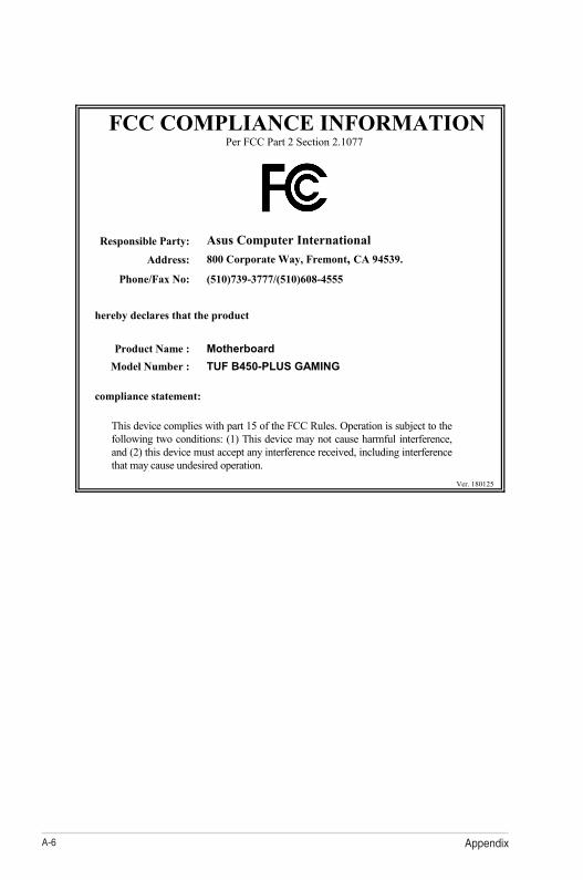
FCC COMPLIANCE INFORMATION Per FCC Part 2 Section 2.1077
Responsible Party: Asus Computer International Address: 800 Corporate Way, Fremont, CA 94539.
Phone/Fax No: (510)739-3777/(510)608-4555
hereby declares that the product
Product Name : Motherboard
Model Number : TUF B450-PLUS GAMING
compliance statement:
This device complies with part 15 of the FCC Rules. Operation is subject to the following two conditions: (1) This device may not cause harmful interference, and (2) this device must accept any interference received, including interference that may cause undesired operation.
Ver. 180125