Embed Size (px)
Citation preview
MP255 1
Workshop I
Tuning LNB’s and OFA Systems
R. Thompson
FERCo, Laguna Hills, CA
2009 Reinhold NOx Roundtable
Cleveland, Ohio
February, 2009
MP255 2
REQUIREMENTS FOR EFFECTIVE NOX OPTIMIZATION
Comprehensive Diagnostic Evaluation of Factors Affecting
NOx Emissions:
- Coal Property Variability
- Burner Pipe Coal Flow Distribution
- Combustion Uniformity (Individual Burner and OFA Settings)
- Post-Combustion NOx Control (SCR/SNCR Grid Tuning)
- Plant Combustion Controls and Process Instrumentation
- SCR Catalyst Performance Degradation and Catalyst
Replacement Management
MP255 3
ROLE OF ADVANCED INSTRUMENTATION IN OPTIMIZATION
Expedient Cost Effective NOx Emissions Diagnostics and
Tuning
- Real-Time Burner Pipe Coal Flow Distribution Measurement
- Real-Time Economizer Exit O2,CO, NO Profiles for
Interactive Burner/OFA Tuning Using Multipoint Emissions
Analyzer
- Quick Turnaround Fly Ash LOI Analysis (Hot Foil Analyzer)
- Rapid Cost Effective SCR/SNCR Tuning Using Real-Time
Multipoint Emissions Analyzer
- Periodic SCR Catalyst Activity Measurement Using In situ
KnoxCheck Advanced Instrumentation System
• FERCo Uses Custom Proprietary Instrumentation in its NOx
Emissions Diagnostics and Process Control Optimization
MP255 4
COMBUSTION DIAGNOSTICS AND TUNING
MP255 5
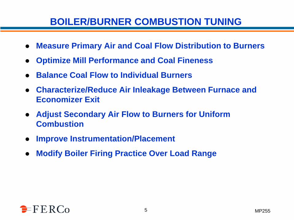
BOILER/BURNER COMBUSTION TUNING
Measure Primary Air and Coal Flow Distribution to Burners
Optimize Mill Performance and Coal Fineness
Balance Coal Flow to Individual Burners
Characterize/Reduce Air Inleakage Between Furnace and
Economizer Exit
Adjust Secondary Air Flow to Burners for Uniform
Combustion
Improve Instrumentation/Placement
Modify Boiler Firing Practice Over Load Range
MP255 6
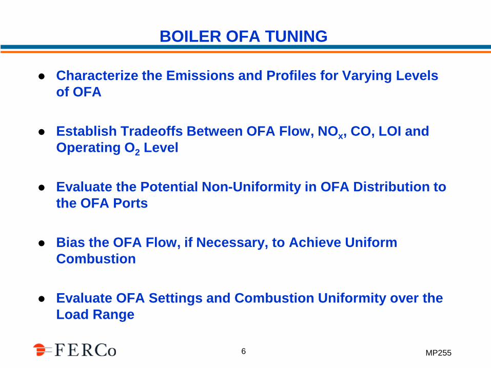
BOILER OFA TUNING
Characterize the Emissions and Profiles for Varying Levels
of OFA
Establish Tradeoffs Between OFA Flow, NOx, CO, LOI and
Operating O2 Level
Evaluate the Potential Non-Uniformity in OFA Distribution to
the OFA Ports
Bias the OFA Flow, if Necessary, to Achieve Uniform
Combustion
Evaluate OFA Settings and Combustion Uniformity over the
Load Range
MP255 7
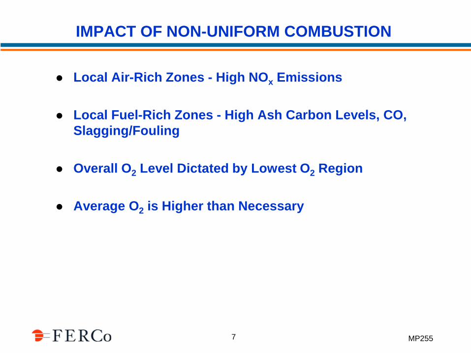
IMPACT OF NON-UNIFORM COMBUSTION
Local Air-Rich Zones - High NOx Emissions
Local Fuel-Rich Zones - High Ash Carbon Levels, CO,
Slagging/Fouling
Overall O2 Level Dictated by Lowest O2 Region
Average O2 is Higher than Necessary
MP255 8
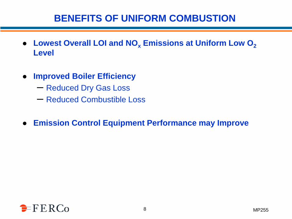
BENEFITS OF UNIFORM COMBUSTION
Lowest Overall LOI and NOx Emissions at Uniform Low O2
Level
Improved Boiler Efficiency
– Reduced Dry Gas Loss
– Reduced Combustible Loss
Emission Control Equipment Performance may Improve
MP255 9
COMMON CAUSES OF NON-UNIFORM COMBUSTION
Uneven Coal Flow Distribution
– Coal Pipe Orifices
– Riffle Box Configuration
– Coal Feeder Calibration or Bias
Uneven Air Flow Distribution
– Air Register/Damper Settings
– Windbox Design, FD Fan Placement
– Air Register/Drive Motor Malfunction
– OFA Ductwork Configuration
Air Heater – Seal Leakage or Partial Pluggage
Furnace Air Inleakage Before O2 Probes
MP255
LIMITATIONS OF STACK (CEM) DATA
Boiler Average Emissions Only, No Indication of Burner
Zone Gradients
No Direct O2 or CO Measurement
Typically Not Real-Time Data to Allow Interactive Burner and
OFA Tuning
Difficult to Evaluate Combustion Uniformity Downstream of
the Air Heater
MP255 11
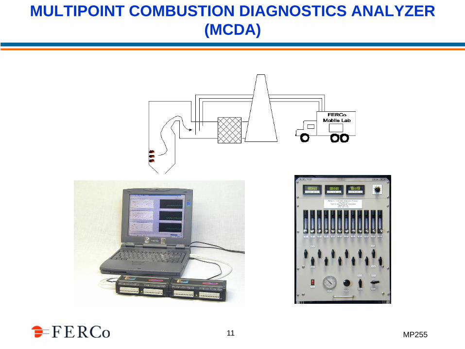
MULTIPOINT COMBUSTION DIAGNOSTICS ANALYZER
(MCDA)
MP255 12
ANALYZER FEATURES AND BENEFITS
Simultaneous Measurement at 12 Sample Points
NO, O2, CO - 12 Channels Each (36 Total)
Real-Time Contour Plots of Gas Concentrations
Identify Non-Uniform Combustion and Air Inleakage
Burner and OFA Tuning in Interactive Mode
MP255 13
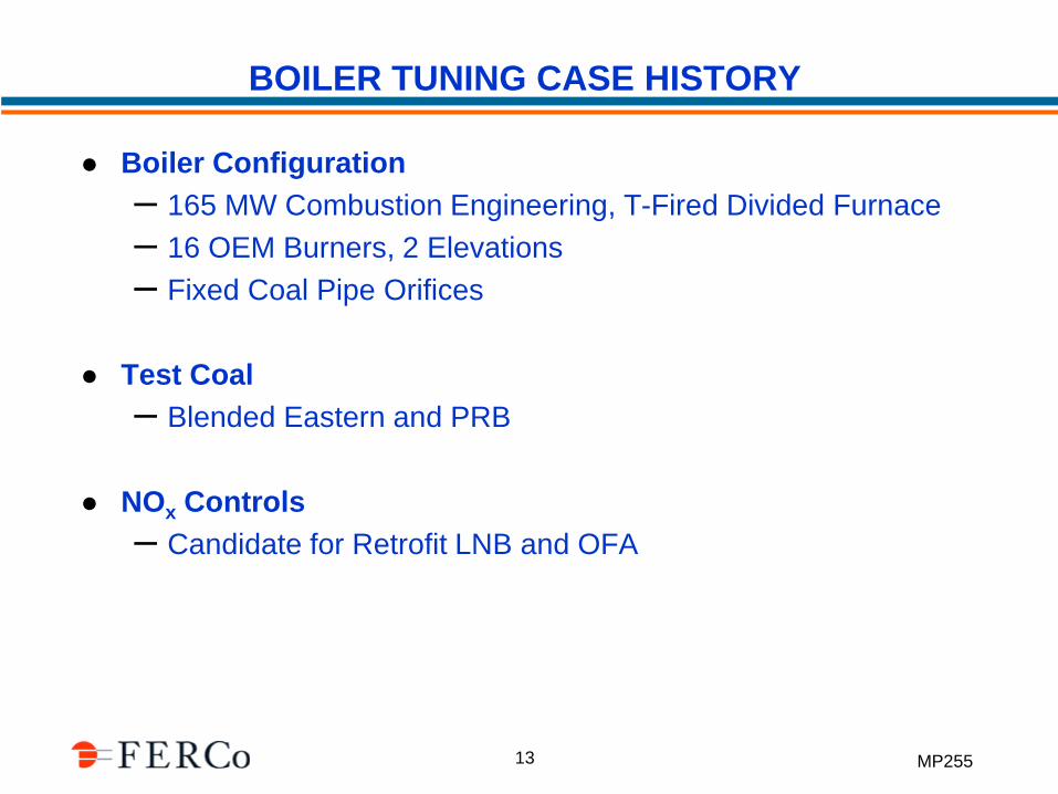
BOILER TUNING CASE HISTORY
Boiler Configuration
– 165 MW Combustion Engineering, T-Fired Divided Furnace
– 16 OEM Burners, 2 Elevations
– Fixed Coal Pipe Orifices
Test Coal
– Blended Eastern and PRB
NOx Controls
– Candidate for Retrofit LNB and OFA
MP255 14
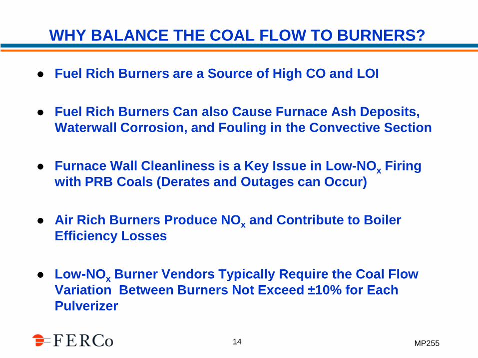
WHY BALANCE THE COAL FLOW TO BURNERS?
Fuel Rich Burners are a Source of High CO and LOI
Fuel Rich Burners Can also Cause Furnace Ash Deposits,
Waterwall Corrosion, and Fouling in the Convective Section
Furnace Wall Cleanliness is a Key Issue in Low-NOx Firing
with PRB Coals (Derates and Outages can Occur)
Air Rich Burners Produce NOx and Contribute to Boiler
Efficiency Losses
Low-NOx Burner Vendors Typically Require the Coal Flow
Variation Between Burners Not Exceed ±10% for Each
Pulverizer
MP255 15
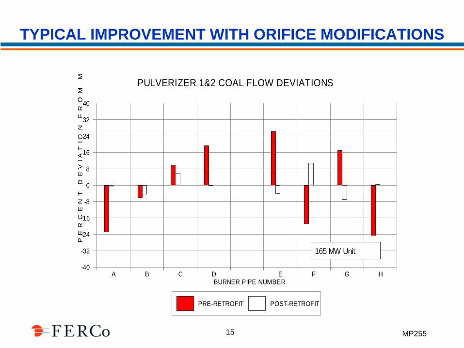
TYPICAL IMPROVEMENT WITH ORIFICE MODIFICATIONS
-40
-32
-24
-16
-8
0
8
16
24
32
40
PE
RC
EN
T D
EV
IA
TIO
N F
RO
M M
EA
N
A B C D E F G HBURNER PIPE NUMBER
PRE-RETROFIT POST-RETROFIT
PULVERIZER 1&2 COAL FLOW DEVIATIONS
165 MW Unit
MP255 16
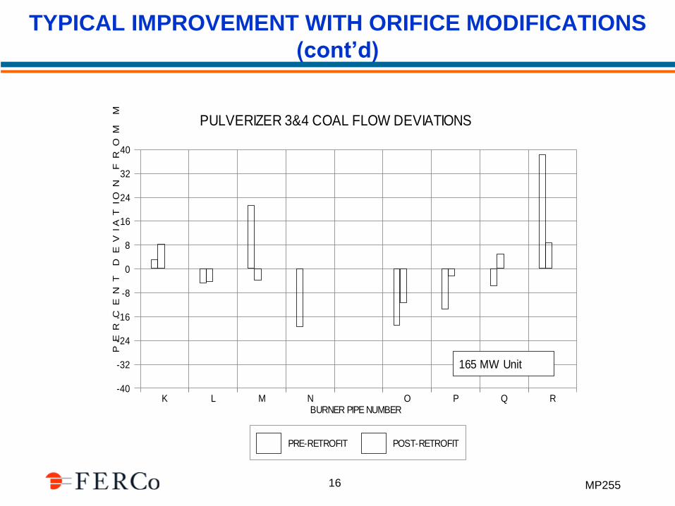
TYPICAL IMPROVEMENT WITH ORIFICE MODIFICATIONS
(cont’d)
-40
-32
-24
-16
-8
0
8
16
24
32
40
PE
RC
EN
T D
EV
IA
TIO
N F
RO
M M
EA
N
K L M N O P Q RBURNER PIPE NUMBER
PRE-RETROFIT POST-RETROFIT
PULVERIZER 3&4 COAL FLOW DEVIATIONS
165 MW Unit
MP255 17
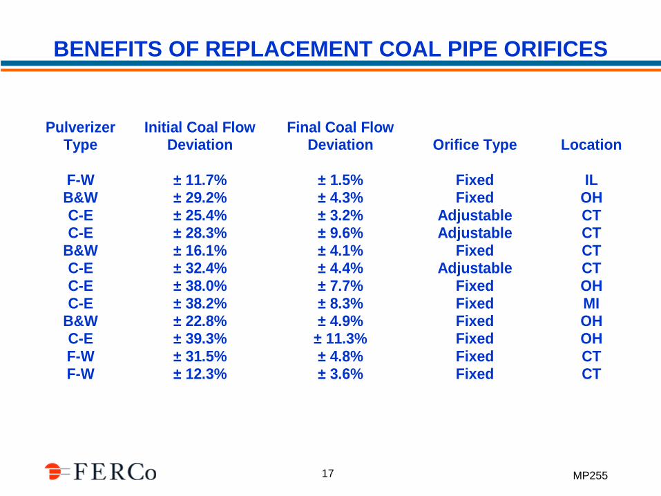
Pulverizer Type
Initial Coal Flow Deviation
Final Coal Flow Deviation Orifice Type Location
F-W ± 11.7% ± 1.5% Fixed IL B&W ± 29.2% ± 4.3% Fixed OH C-E ± 25.4% ± 3.2% Adjustable CT C-E ± 28.3% ± 9.6% Adjustable CT
B&W ± 16.1% ± 4.1% Fixed CT C-E ± 32.4% ± 4.4% Adjustable CT C-E ± 38.0% ± 7.7% Fixed OH C-E ± 38.2% ± 8.3% Fixed MI
B&W ± 22.8% ± 4.9% Fixed OH C-E ± 39.3% ± 11.3% Fixed OH F-W ± 31.5% ± 4.8% Fixed CT F-W ± 12.3% ± 3.6% Fixed CT
BENEFITS OF REPLACEMENT COAL PIPE ORIFICES
MP255 18
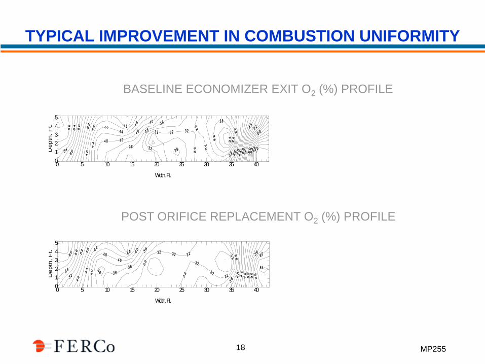
TYPICAL IMPROVEMENT IN COMBUSTION UNIFORMITY
0 5 10 15 20 25 30 35 40
Width, Ft.
0
1
2
3
4
5
Dep
th,
Ft.
0 5 10 15 20 25 30 35 40
Width, Ft.
0
1
2
3
4
5
Depth
, F
t.
BASELINE ECONOMIZER EXIT O2 (%) PROFILE
POST ORIFICE REPLACEMENT O2 (%) PROFILE
MP255 19
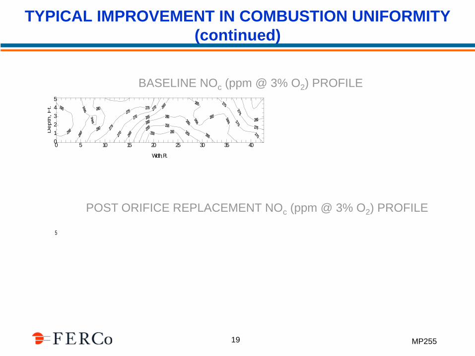
TYPICAL IMPROVEMENT IN COMBUSTION UNIFORMITY
(continued)
BASELINE NOc (ppm @ 3% O2) PROFILE
POST ORIFICE REPLACEMENT NOc (ppm @ 3% O2) PROFILE
0 5 10 15 20 25 30 35 40
Width, Ft.
0
1
2
3
4
5
Dep
th,
Ft.
0 5 10 15 20 25 30 35 40
Width, Ft.
0
1
2
3
4
5
Depth
, Ft.
MP255 20
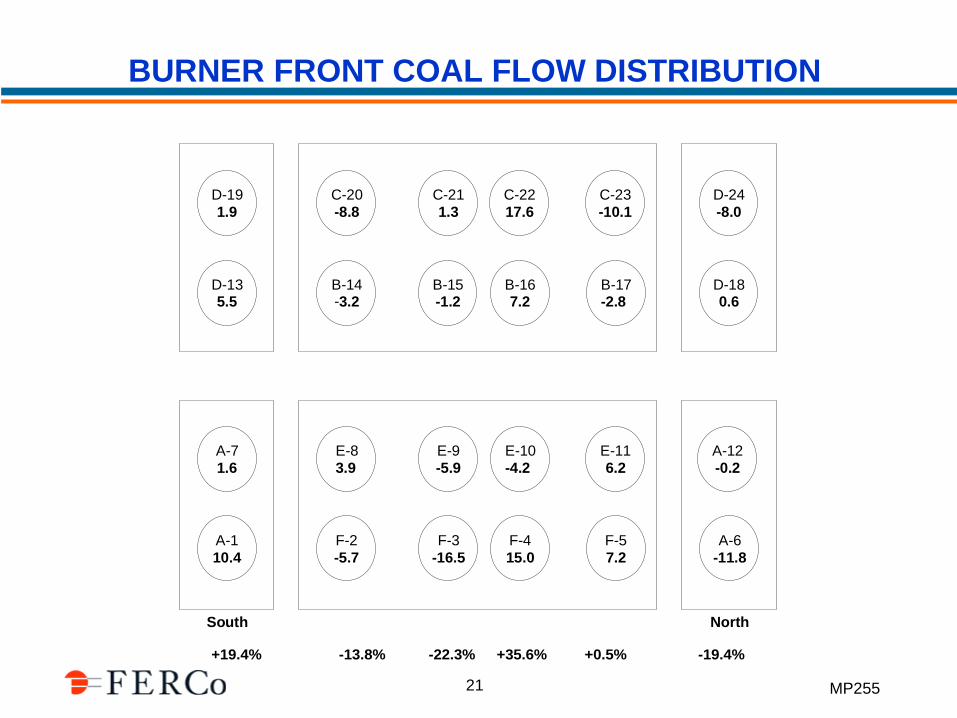
BOILER TUNING CASE HISTORY
Boiler Configuration
– 260 MW Babcock & Wilcox, Front Wall-Fired
– 24 Low-NOx Burners (4 x 6), 6 Overfire Air Ports
– Adjustable Coal Pipe Orifices, Dynamic Classifiers
Test Coal
– Blended Eastern and PRB
Post-Combustion NOx Control
– Babcock & Wilcox SCR
MP255 21
BURNER FRONT COAL FLOW DISTRIBUTION
+19.4% -13.8% -22.3% +35.6% +0.5% -19.4%
D-19
1.9
D-135.5
A-7
1.6
A-1
10.4
A-12
-0.2
A-6
-11.8
D-24
-8.0
D-180.6
C-20
-8.8
B-14-3.2
C-21
1.3
B-15-1.2
C-22
17.6
B-167.2
C-23
-10.1
B-17-2.8
E-8
3.9
F-2
-5.7
E-9
-5.9
E-10
-4.2
F-4
15.0
E-11
6.2
F-5
7.2
NorthSouth
F-3
-16.5
MP255 22
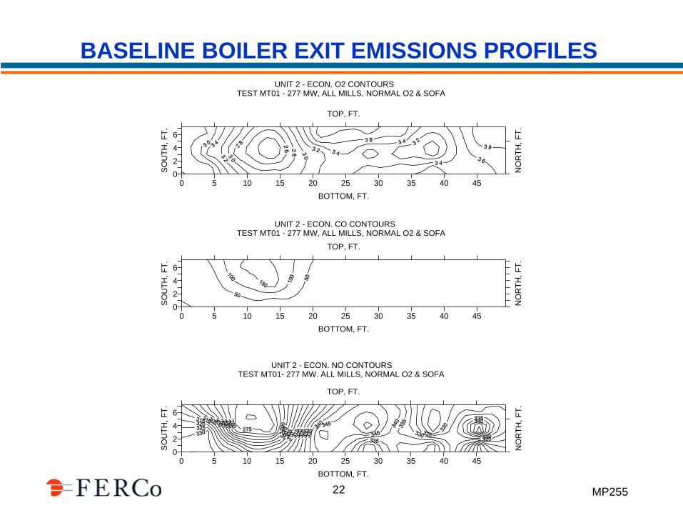
BASELINE BOILER EXIT EMISSIONS PROFILES
0 5 10 15 20 25 30 35 40 45
BOTTOM, FT.
TOP, FT.
0
2
4
6
SO
UT
H, F
T.
NO
RT
H, F
T.
UNIT 2 - ECON. O2 CONTOURSTEST MT01 - 277 MW, ALL MILLS, NORMAL O2 & SOFA
0 5 10 15 20 25 30 35 40 45
BOTTOM, FT.
TOP, FT.
0
2
4
6
SO
UT
H, F
T.
NO
RT
H, F
T.
0 5 10 15 20 25 30 35 40 45
BOTTOM, FT.
TOP, FT.
0
2
4
6
SO
UT
H, F
T.
NO
RT
H, F
T.
UNIT 2 - ECON. CO CONTOURSTEST MT01 - 277 MW, ALL MILLS, NORMAL O2 & SOFA
UNIT 2 - ECON. NO CONTOURSTEST MT01- 277 MW. ALL MILLS, NORMAL O2 & SOFA
MP255 23
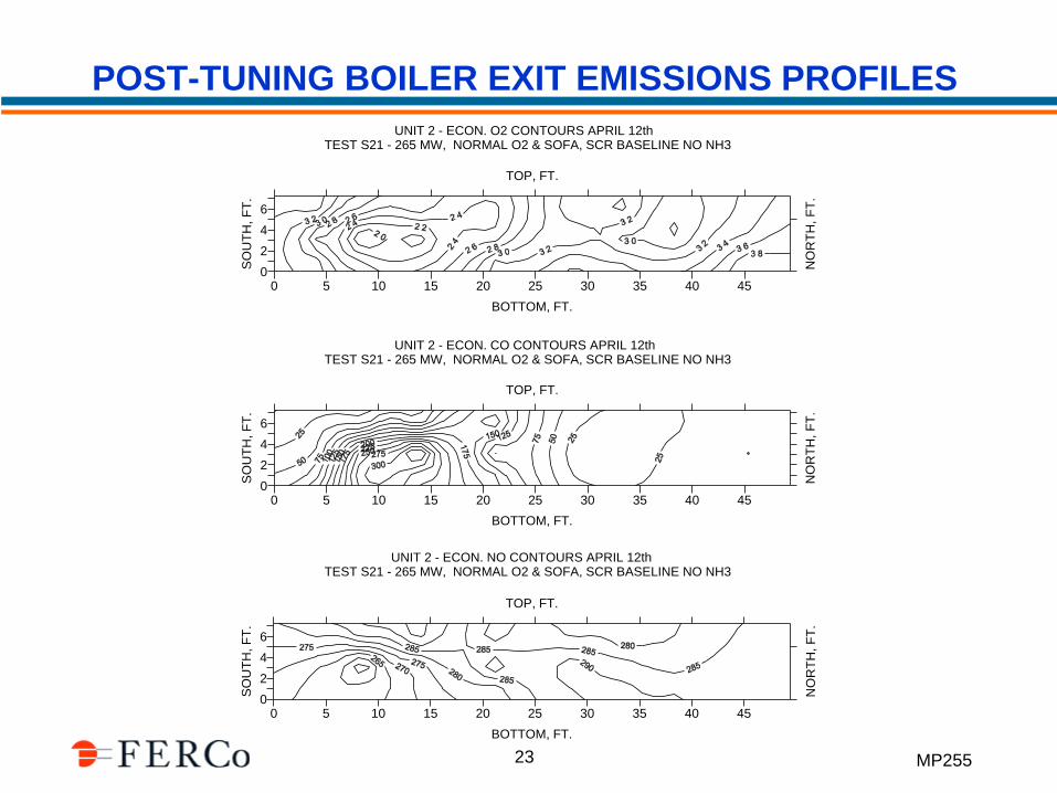
POST-TUNING BOILER EXIT EMISSIONS PROFILES
0 5 10 15 20 25 30 35 40 45
BOTTOM, FT.
TOP, FT.
0
2
4
6
SO
UT
H, F
T.
NO
RT
H, F
T.
UNIT 2 - ECON. O2 CONTOURS APRIL 12thTEST S21 - 265 MW, NORMAL O2 & SOFA, SCR BASELINE NO NH3
0 5 10 15 20 25 30 35 40 45
BOTTOM, FT.
TOP, FT.
0
2
4
6
SO
UT
H, F
T.
NO
RT
H, F
T.
0 5 10 15 20 25 30 35 40 45
BOTTOM, FT.
TOP, FT.
0
2
4
6
SO
UT
H, F
T.
NO
RT
H, F
T.
UNIT 2 - ECON. CO CONTOURS APRIL 12thTEST S21 - 265 MW, NORMAL O2 & SOFA, SCR BASELINE NO NH3
UNIT 2 - ECON. NO CONTOURS APRIL 12thTEST S21 - 265 MW, NORMAL O2 & SOFA, SCR BASELINE NO NH3
MP255 24
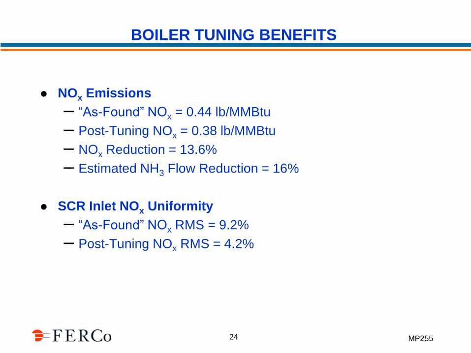
BOILER TUNING BENEFITS
NOx Emissions
– “As-Found” NOx = 0.44 lb/MMBtu
– Post-Tuning NOx = 0.38 lb/MMBtu
– NOx Reduction = 13.6%
– Estimated NH3 Flow Reduction = 16%
SCR Inlet NOx Uniformity
– “As-Found” NOx RMS = 9.2%
– Post-Tuning NOx RMS = 4.2%
MP255 25
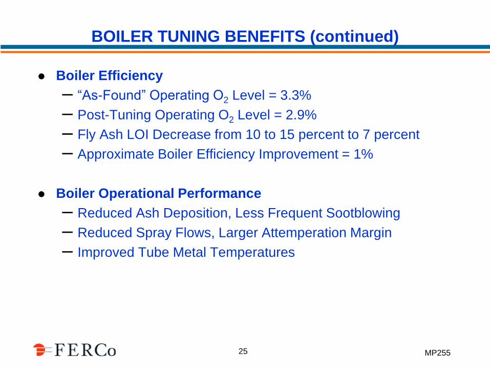
BOILER TUNING BENEFITS (continued)
Boiler Efficiency
– “As-Found” Operating O2 Level = 3.3%
– Post-Tuning Operating O2 Level = 2.9%
– Fly Ash LOI Decrease from 10 to 15 percent to 7 percent
– Approximate Boiler Efficiency Improvement = 1%
Boiler Operational Performance
– Reduced Ash Deposition, Less Frequent Sootblowing
– Reduced Spray Flows, Larger Attemperation Margin
– Improved Tube Metal Temperatures
MP255 26
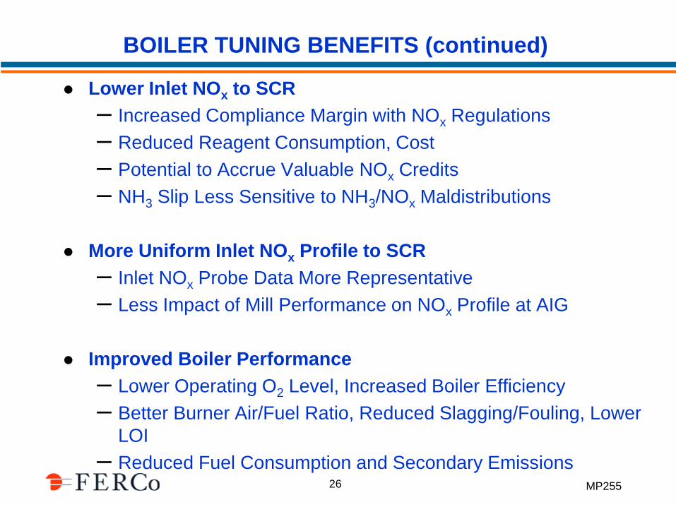
BOILER TUNING BENEFITS (continued)
Lower Inlet NOx to SCR
– Increased Compliance Margin with NOx Regulations
– Reduced Reagent Consumption, Cost
– Potential to Accrue Valuable NOx Credits
– NH3 Slip Less Sensitive to NH3/NOx Maldistributions
More Uniform Inlet NOx Profile to SCR
– Inlet NOx Probe Data More Representative
– Less Impact of Mill Performance on NOx Profile at AIG
Improved Boiler Performance
– Lower Operating O2 Level, Increased Boiler Efficiency
– Better Burner Air/Fuel Ratio, Reduced Slagging/Fouling, Lower
LOI
– Reduced Fuel Consumption and Secondary Emissions
MP255 27
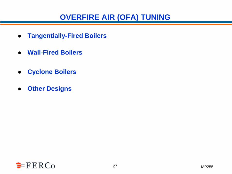
OVERFIRE AIR (OFA) TUNING
Tangentially-Fired Boilers
Wall-Fired Boilers
Cyclone Boilers
Other Designs
MP255 28
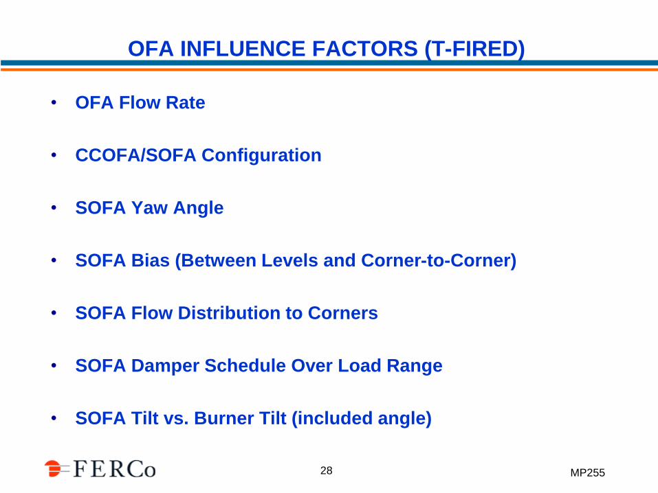
OFA INFLUENCE FACTORS (T-FIRED)
• OFA Flow Rate
• CCOFA/SOFA Configuration
• SOFA Yaw Angle
• SOFA Bias (Between Levels and Corner-to-Corner)
• SOFA Flow Distribution to Corners
• SOFA Damper Schedule Over Load Range
• SOFA Tilt vs. Burner Tilt (included angle)
MP255 29
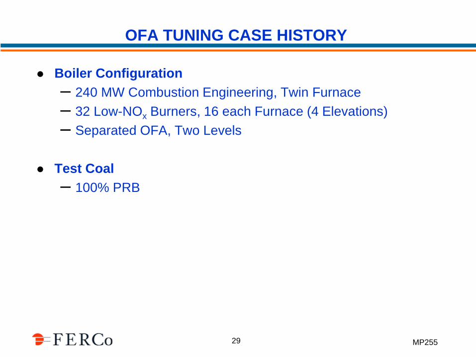
OFA TUNING CASE HISTORY
Boiler Configuration
– 240 MW Combustion Engineering, Twin Furnace
– 32 Low-NOx Burners, 16 each Furnace (4 Elevations)
– Separated OFA, Two Levels
Test Coal
– 100% PRB
MP255 30
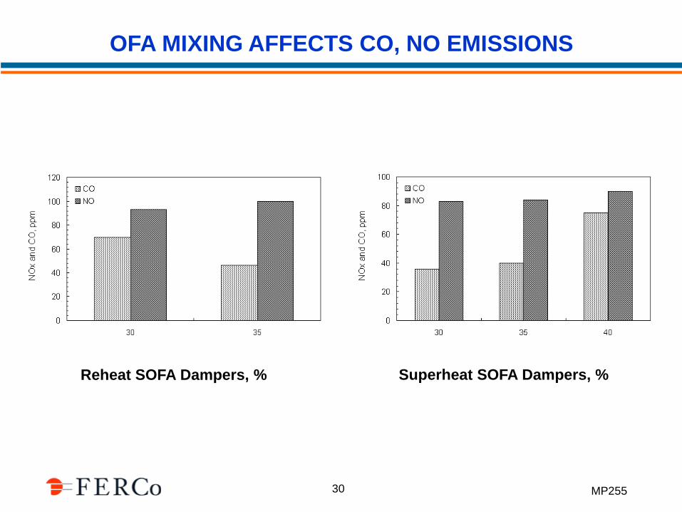
OFA MIXING AFFECTS CO, NO EMISSIONS
Reheat SOFA Dampers, % Superheat SOFA Dampers, %
MP255 31
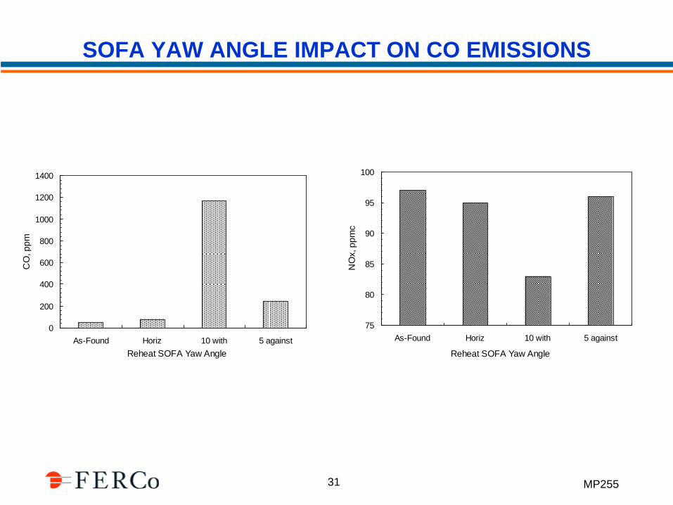
SOFA YAW ANGLE IMPACT ON CO EMISSIONS
0
200
400
600
800
1000
1200
1400
As-Found Horiz 10 with 5 against
Reheat SOFA Yaw Angle
CO
, p
pm
75
80
85
90
95
100
As-Found Horiz 10 with 5 against
Reheat SOFA Yaw AngleN
Ox, p
pm
c
MP255 32
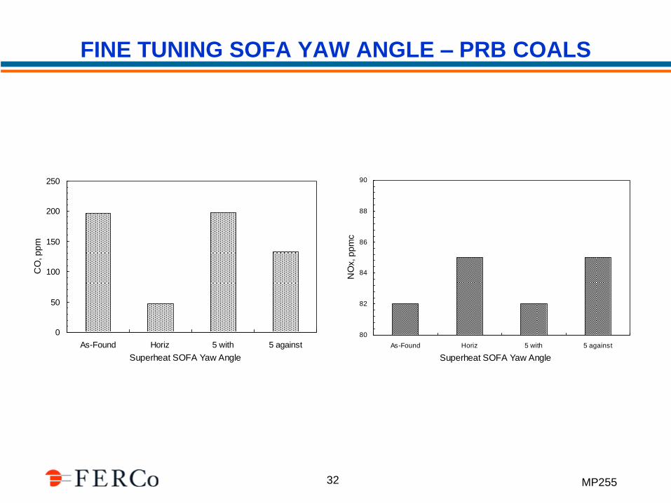
FINE TUNING SOFA YAW ANGLE – PRB COALS
0
50
100
150
200
250
As-Found Horiz 5 with 5 against
Superheat SOFA Yaw Angle
CO
, p
pm
80
82
84
86
88
90
As-Found Horiz 5 with 5 against
Superheat SOFA Yaw AngleN
Ox, p
pm
c
MP255 33
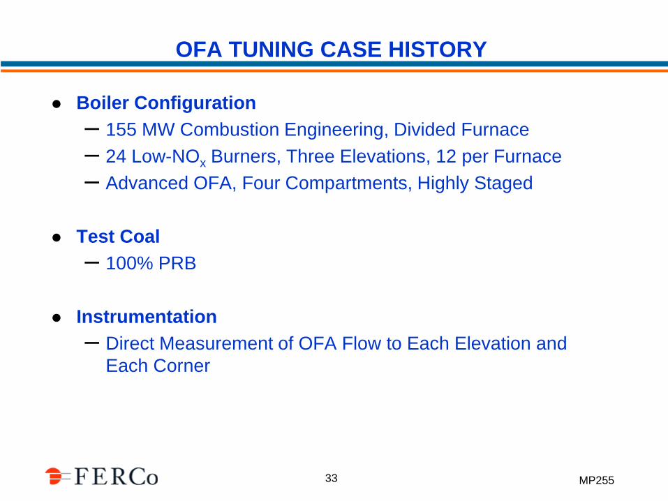
OFA TUNING CASE HISTORY
Boiler Configuration
– 155 MW Combustion Engineering, Divided Furnace
– 24 Low-NOx Burners, Three Elevations, 12 per Furnace
– Advanced OFA, Four Compartments, Highly Staged
Test Coal
– 100% PRB
Instrumentation
– Direct Measurement of OFA Flow to Each Elevation and
Each Corner
MP255 34
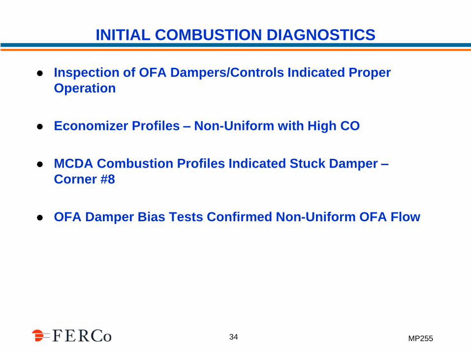
INITIAL COMBUSTION DIAGNOSTICS
Inspection of OFA Dampers/Controls Indicated Proper
Operation
Economizer Profiles – Non-Uniform with High CO
MCDA Combustion Profiles Indicated Stuck Damper –
Corner #8
OFA Damper Bias Tests Confirmed Non-Uniform OFA Flow
MP255 35
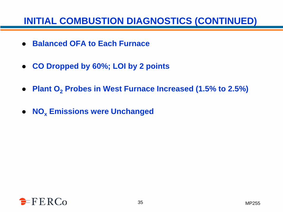
INITIAL COMBUSTION DIAGNOSTICS (CONTINUED)
Balanced OFA to Each Furnace
CO Dropped by 60%; LOI by 2 points
Plant O2 Probes in West Furnace Increased (1.5% to 2.5%)
NOx Emissions were Unchanged
MP255 36
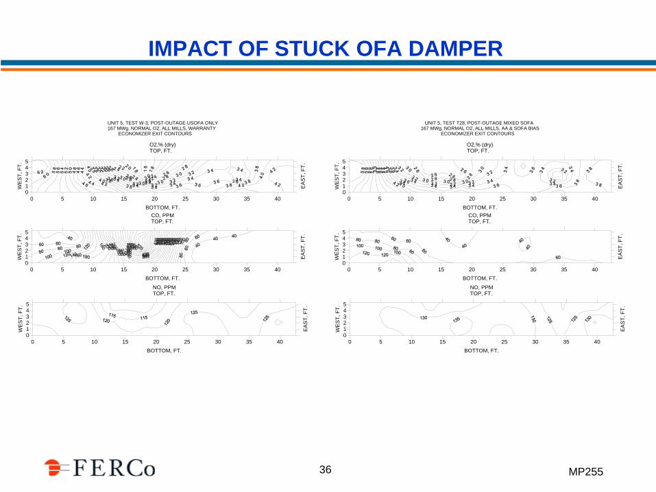
IMPACT OF STUCK OFA DAMPER
0 5 10 15 20 25 30 35 40
BOTTOM, FT.
O2,% (dry)TOP, FT.
012345
WE
ST
, F
T.
EA
ST
, F
T.
0 5 10 15 20 25 30 35 40
BOTTOM, FT.
NO, PPMTOP, FT.
012345
WE
ST
, F
T.
EA
ST
, F
T.
UNIT 5, TEST W-3, POST-OUTAGE USOFA ONLY 167 MWg, NORMAL O2, ALL MILLS, WARRANTY ECONOMIZER EXIT CONTOURS
0 5 10 15 20 25 30 35 40
BOTTOM, FT.
CO, PPMTOP, FT.
012345
WE
ST
, F
T.
EA
ST
, F
T.
0 5 10 15 20 25 30 35 40
BOTTOM, FT.
O2,% (dry)TOP, FT.
012345
WE
ST
, F
T.
EA
ST
, F
T.
0 5 10 15 20 25 30 35 40
BOTTOM, FT.
NO, PPMTOP, FT.
012345
WE
ST
, F
T.
EA
ST
, F
T.
UNIT 5, TEST T28, POST-OUTAGE MIXED SOFA 167 MWg, NORMAL O2, ALL MILLS, AA & SOFA BIAS ECONOMIZER EXIT CONTOURS
0 5 10 15 20 25 30 35 40
BOTTOM, FT.
CO, PPMTOP, FT.
012345
WE
ST
, F
T.
EA
ST
, F
T.
MP255 37
OBSERVATIONS FROM HIGH OFA DIAGNOSTIC TESTS
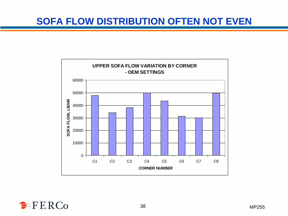
Distribution of OFA to Furnace Corners often is Uneven on Retrofit OFA Systems
Direct Measurement of OFA Flow to Corners is Valuable in Tuning OFA Systems
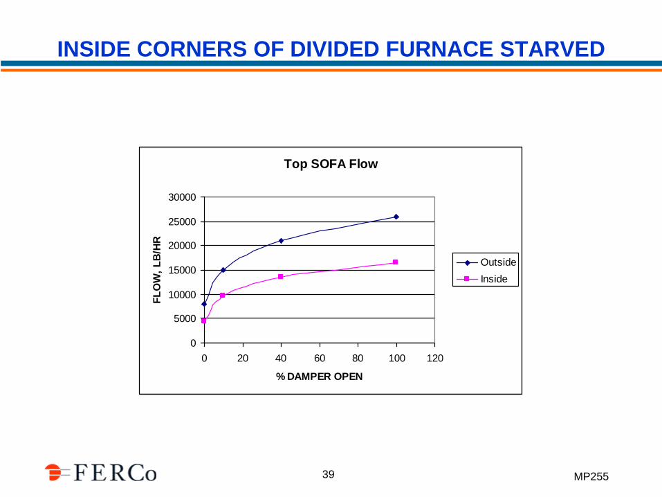
“Inside” Corners on T-Fired Divided Furnace Designs May Get Less OFA Flow than “Outside” Corners
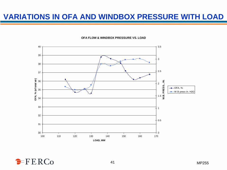
OFA Flow and Windbox Pressure Should be Monitored Over the Load Range to Confirm Desired Staging
Modification to Plant O2 Probe Locations May be Necessary
Calculations and Display of OFA Staging on DCS is Recommended (not just damper position)
MP255 38
SOFA FLOW DISTRIBUTION OFTEN NOT EVEN
UPPER SOFA FLOW VARIATION BY CORNER
- OEM SETTINGS
0
10000
20000
30000
40000
50000
60000
C1 C2 C3 C4 C5 C6 C7 C8
CORNER NUMBER
SO
FA
FL
OW
, L
B/H
R
MP255 39
INSIDE CORNERS OF DIVIDED FURNACE STARVED
Top SOFA Flow
0
5000
10000
15000
20000
25000
30000
0 20 40 60 80 100 120
% DAMPER OPEN
FL
OW
, L
B/H
R
Outside
Inside
MP255 40
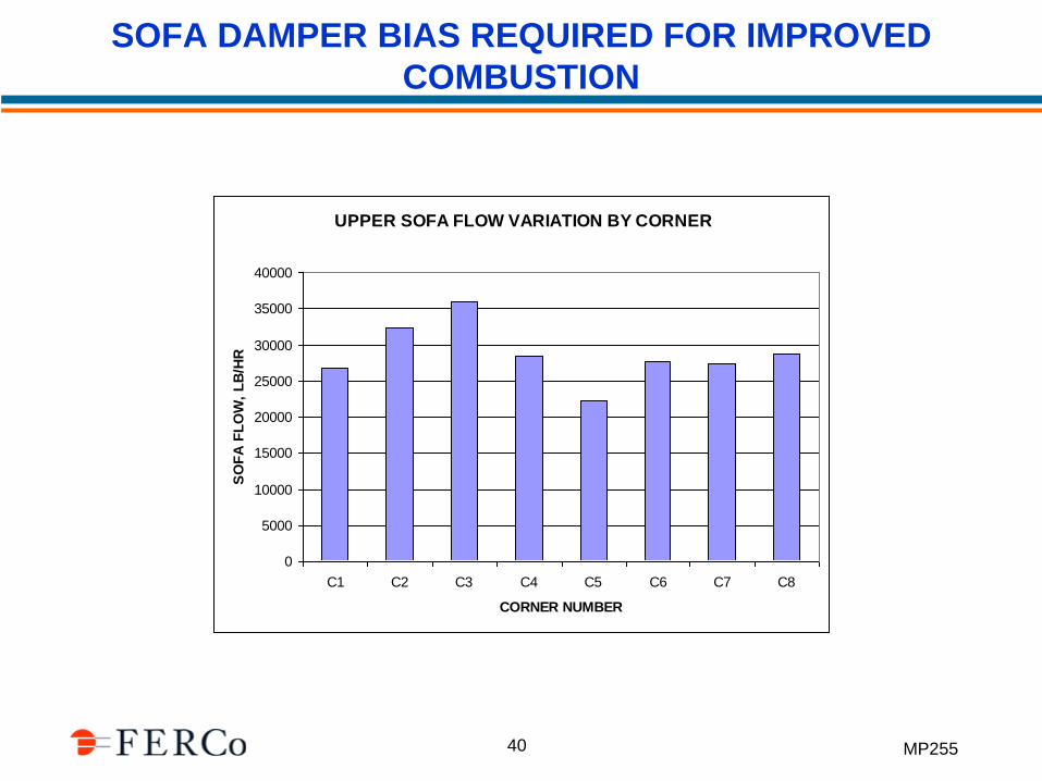
SOFA DAMPER BIAS REQUIRED FOR IMPROVED
COMBUSTION
UPPER SOFA FLOW VARIATION BY CORNER
0
5000
10000
15000
20000
25000
30000
35000
40000
C1 C2 C3 C4 C5 C6 C7 C8
CORNER NUMBER
SO
FA
FL
OW
, L
B/H
R
MP255 41
VARIATIONS IN OFA AND WINDBOX PRESSURE WITH LOAD
OFA FLOW & WINDBOX PRESSURE VS. LOAD
30
31
32
33
34
35
36
37
38
39
40
100 110 120 130 140 150 160 170
LOAD, MW
OF
A,
% (
of
tota
l ai
r)
0
0.5
1
1.5
2
2.5
3
3.5
W.B
. P
RE
SS
., I
N.
OFA, %
W.B press in. H2O
MP255 42
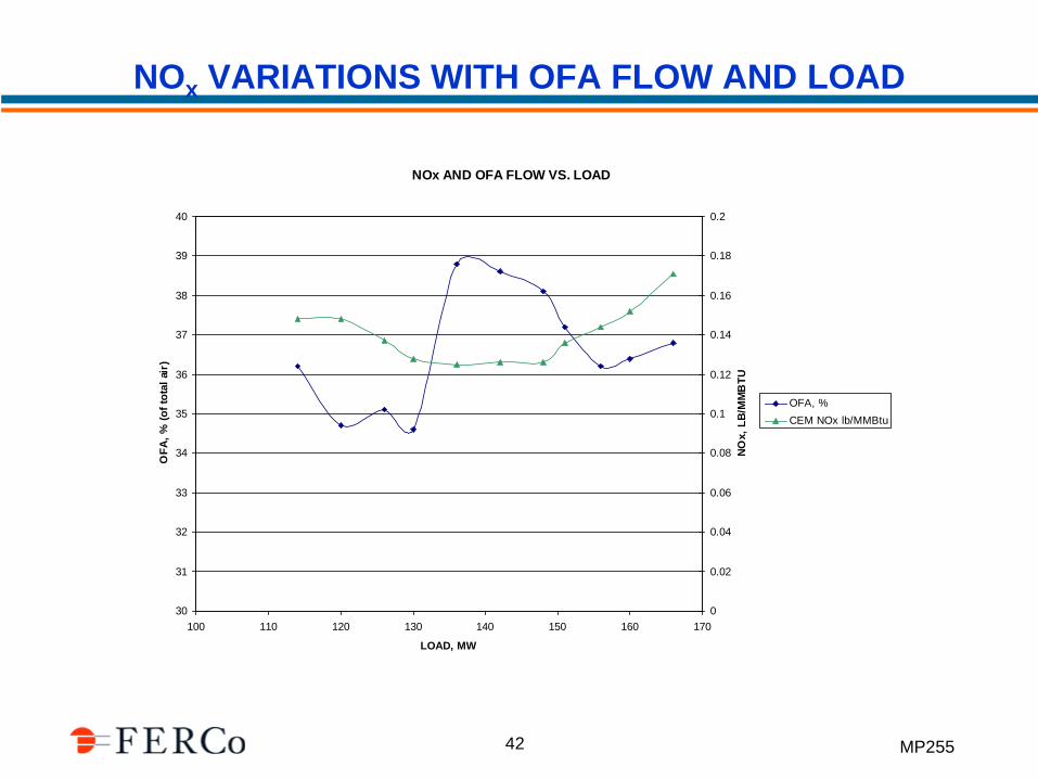
NOx VARIATIONS WITH OFA FLOW AND LOAD
NOx AND OFA FLOW VS. LOAD
30
31
32
33
34
35
36
37
38
39
40
100 110 120 130 140 150 160 170
LOAD, MW
OF
A,
% (
of
tota
l ai
r)
0
0.02
0.04
0.06
0.08
0.1
0.12
0.14
0.16
0.18
0.2
NO
x,
LB
/MM
BT
U
OFA, %
CEM NOx lb/MMBtu
MP255 43
SEPARATE SOFA DAMPER SCHEDULES BY CORNER
0
20
40
60
80
100
120
0 200 400 600 800 1000 1200
STEAM FLOW, KLB/HR
DA
MP
ER
, %
CCOFA, % open
SOFA 3 CORNER 1DMPR POSITION, %
SOFA 3 CORNER 2DMPR POSITION, %
SOFA 3 CORNER 3DMPR POSITION, %
SOFA 3 CORNER 4DMPR POSITION, %
SOFA 3 CORNER 5DMPR POSITION, %
SOFA 3 CORNER 6DMPR POSITION, %
SOFA 3 CORNER 7DMPR POSITION, %
SOFA 3 CORNER 8DMPR POSITION, %
MP255 44
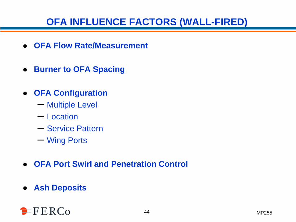
OFA INFLUENCE FACTORS (WALL-FIRED)
OFA Flow Rate/Measurement
Burner to OFA Spacing
OFA Configuration
– Multiple Level
– Location
– Service Pattern
– Wing Ports
OFA Port Swirl and Penetration Control
Ash Deposits
MP255 45
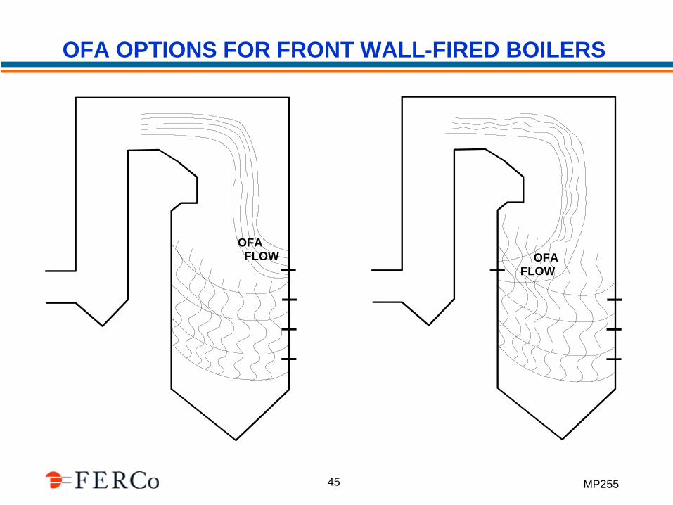
OFA OPTIONS FOR FRONT WALL-FIRED BOILERS
OFA FLOW OFA
FLOW
MP255 46
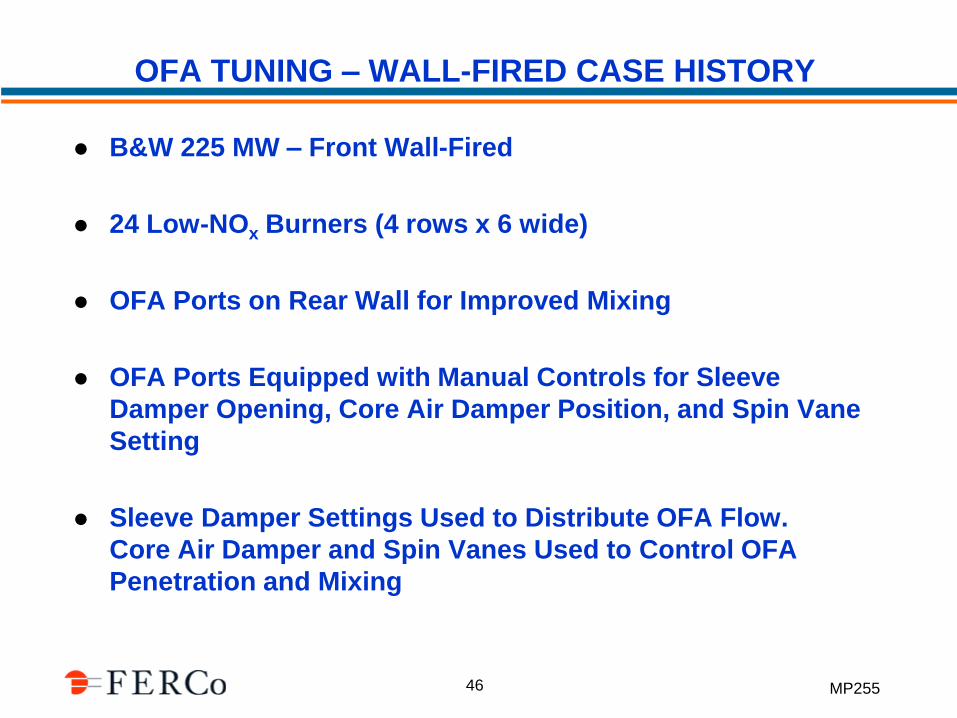
OFA TUNING – WALL-FIRED CASE HISTORY
B&W 225 MW – Front Wall-Fired
24 Low-NOx Burners (4 rows x 6 wide)
OFA Ports on Rear Wall for Improved Mixing
OFA Ports Equipped with Manual Controls for Sleeve
Damper Opening, Core Air Damper Position, and Spin Vane
Setting
Sleeve Damper Settings Used to Distribute OFA Flow.
Core Air Damper and Spin Vanes Used to Control OFA
Penetration and Mixing
MP255 47
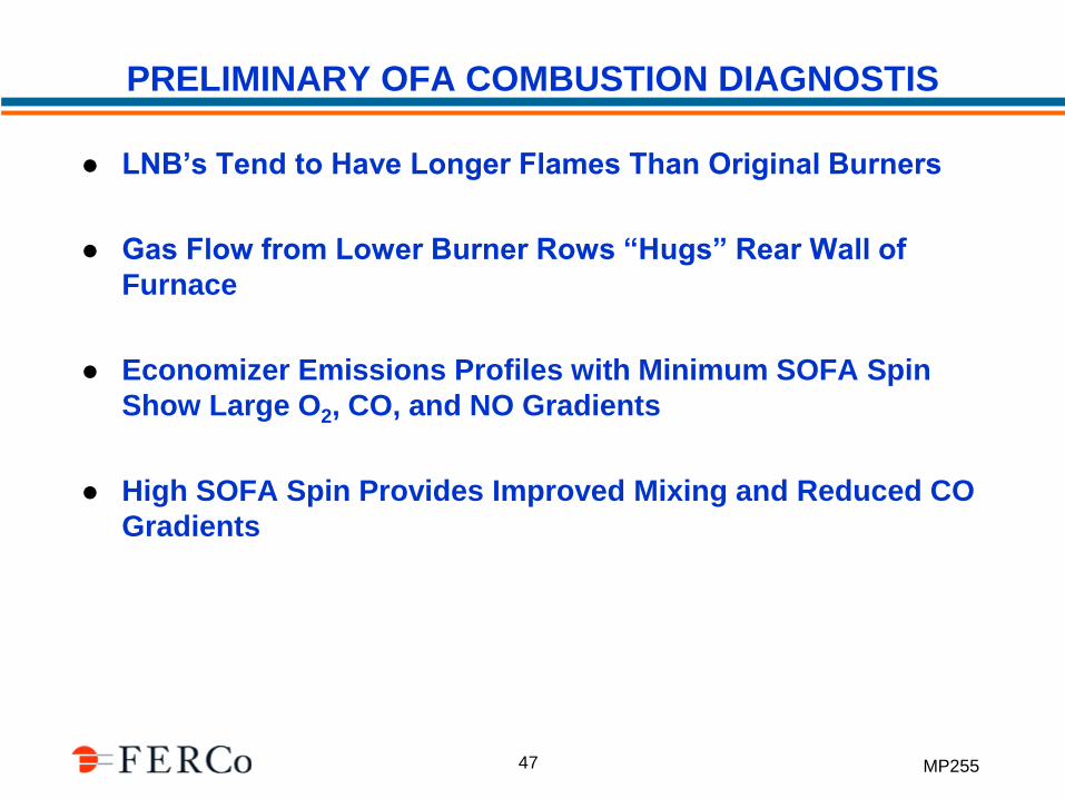
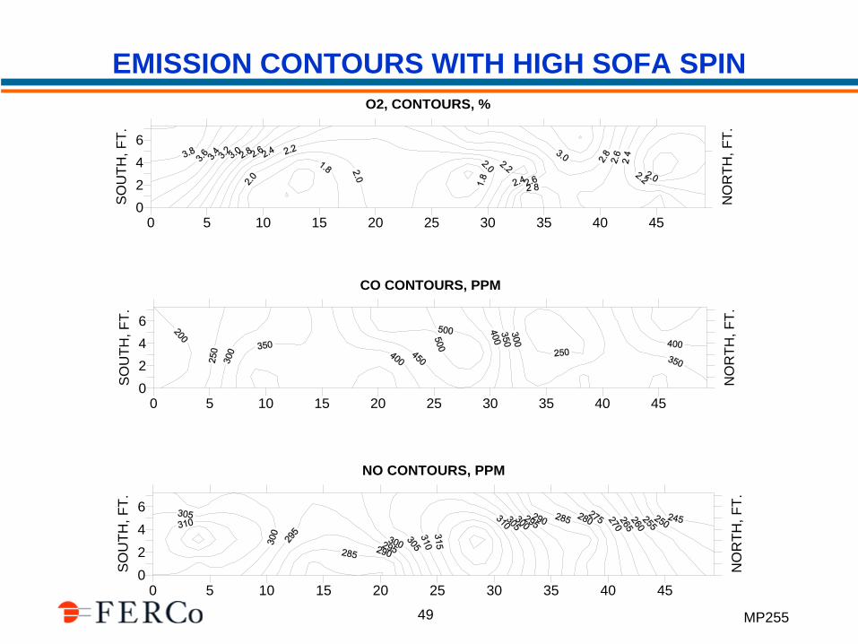
PRELIMINARY OFA COMBUSTION DIAGNOSTIS
LNB’s Tend to Have Longer Flames Than Original Burners
Gas Flow from Lower Burner Rows “Hugs” Rear Wall of
Furnace
Economizer Emissions Profiles with Minimum SOFA Spin
Show Large O2, CO, and NO Gradients
High SOFA Spin Provides Improved Mixing and Reduced CO
Gradients
MP255 48
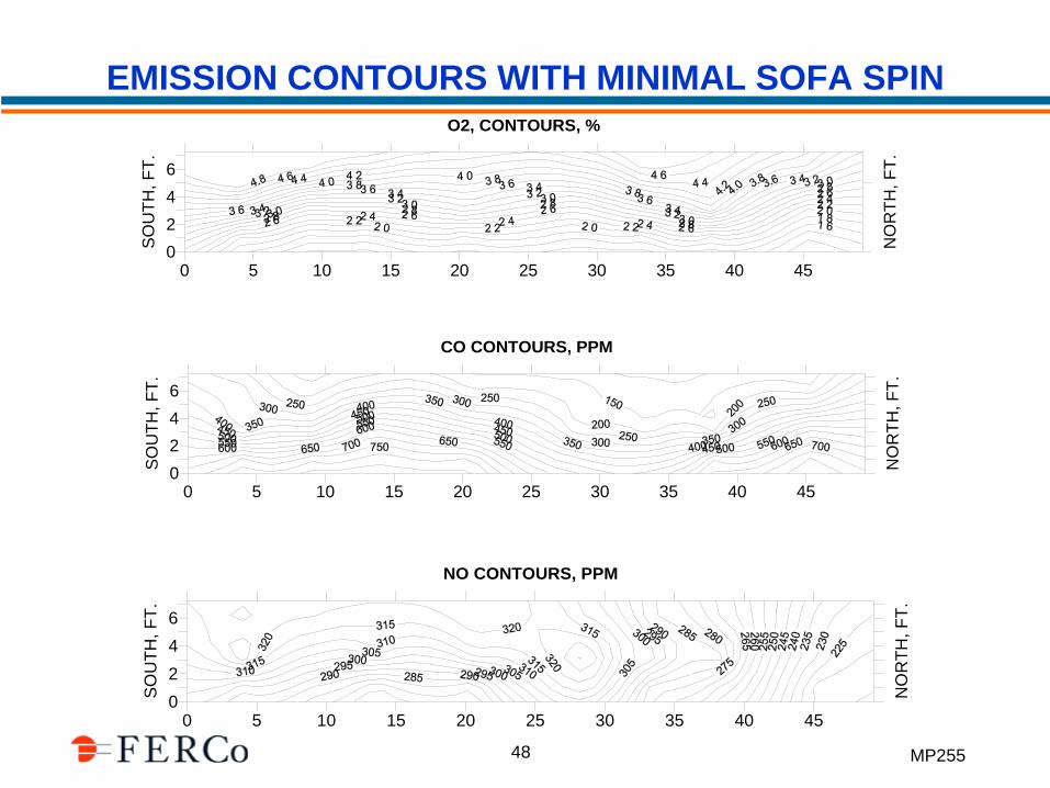
EMISSION CONTOURS WITH MINIMAL SOFA SPIN
0 5 10 15 20 25 30 35 40 45
CO CONTOURS, PPM
0
2
4
6
SO
UT
H,
FT
.
NO
RT
H,
FT
.
0 5 10 15 20 25 30 35 40 45
O2, CONTOURS, %
0
2
4
6
SO
UT
H, F
T.
NO
RT
H, F
T.
0 5 10 15 20 25 30 35 40 45
NO CONTOURS, PPM
0
2
4
6
SO
UT
H,
FT
.
NO
RT
H,
FT
.
MP255 49
EMISSION CONTOURS WITH HIGH SOFA SPIN
0 5 10 15 20 25 30 35 40 45
CO CONTOURS, PPM
0
2
4
6
SO
UT
H,
FT
.
NO
RT
H,
FT
.
0 5 10 15 20 25 30 35 40 45
O2, CONTOURS, %
0
2
4
6
SO
UT
H, F
T.
NO
RT
H, F
T.
0 5 10 15 20 25 30 35 40 45
NO CONTOURS, PPM
0
2
4
6
SO
UT
H,
FT
.
NO
RT
H,
FT
.
MP255 50
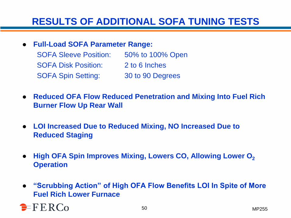
RESULTS OF ADDITIONAL SOFA TUNING TESTS
Full-Load SOFA Parameter Range:
SOFA Sleeve Position: 50% to 100% Open
SOFA Disk Position: 2 to 6 Inches
SOFA Spin Setting: 30 to 90 Degrees
Reduced OFA Flow Reduced Penetration and Mixing Into Fuel Rich
Burner Flow Up Rear Wall
LOI Increased Due to Reduced Mixing, NO Increased Due to
Reduced Staging
High OFA Spin Improves Mixing, Lowers CO, Allowing Lower O2
Operation
“Scrubbing Action” of High OFA Flow Benefits LOI In Spite of More
Fuel Rich Lower Furnace
MP255 51
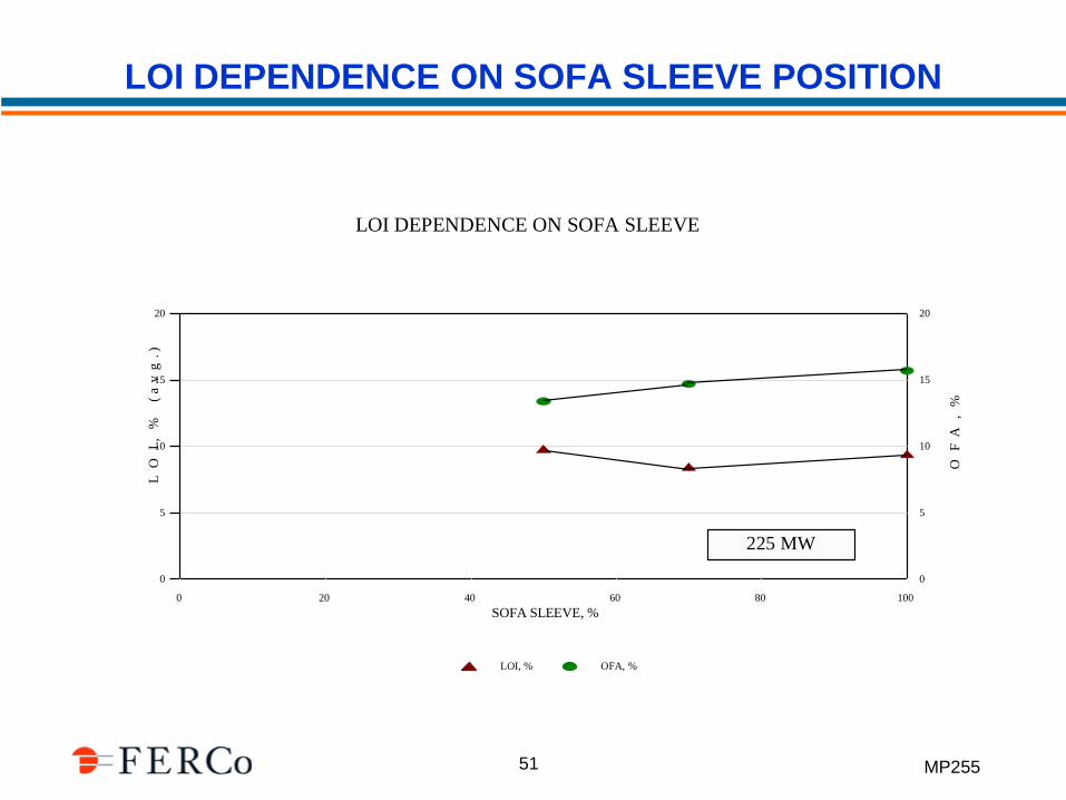
LOI DEPENDENCE ON SOFA SLEEVE POSITION
0
5
10
15
20
LO
I, %
(
av
g.)
0
5
10
15
20
OF
A,
%
0 20 40 60 80 100
SOFA SLEEVE, %
LOI, % OFA, %
LOI DEPENDENCE ON SOFA SLEEVED.E. KARN UNIT 2 - TUNE (2/2000)
225 MW
MP255 52
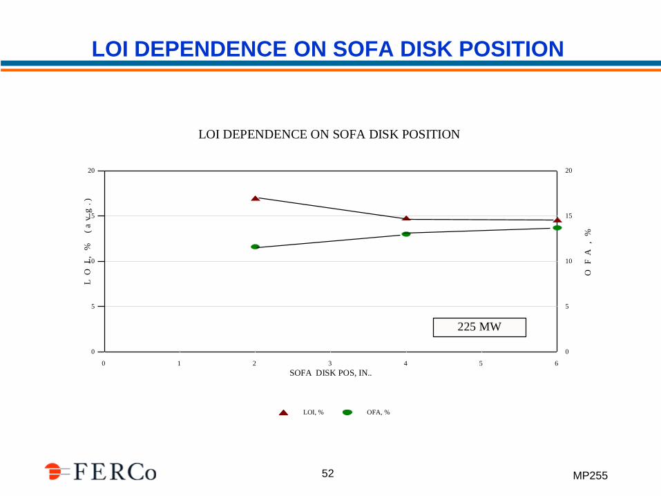
LOI DEPENDENCE ON SOFA DISK POSITION
0
5
10
15
20
LO
I, %
(
av
g.)
0
5
10
15
20
OF
A,
%
0 1 2 3 4 5 6
SOFA DISK POS, IN..
LOI, % OFA, %
LOI DEPENDENCE ON SOFA DISK POSITIOND.E. KARN UNIT 2 - TUNE (2/2000)
225 MW
MP255 53
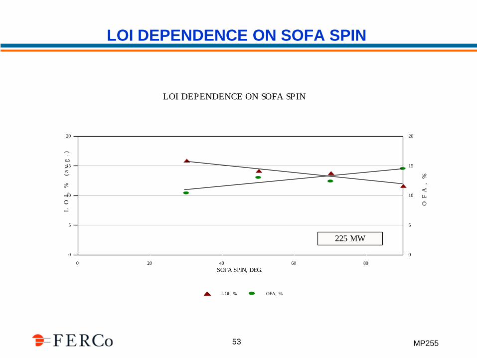
LOI DEPENDENCE ON SOFA SPIN
0
5
10
15
20
LO
I, %
(a
vg
.)
0
5
10
15
20
OF
A, %
0 20 40 60 80
SOFA SPIN, DEG.
LOI, % OFA, %
LOI DEPENDENCE ON SOFA SPIND.E. KARN UNIT 2 - TUNE (2/2000)
225 MW
MP255 54
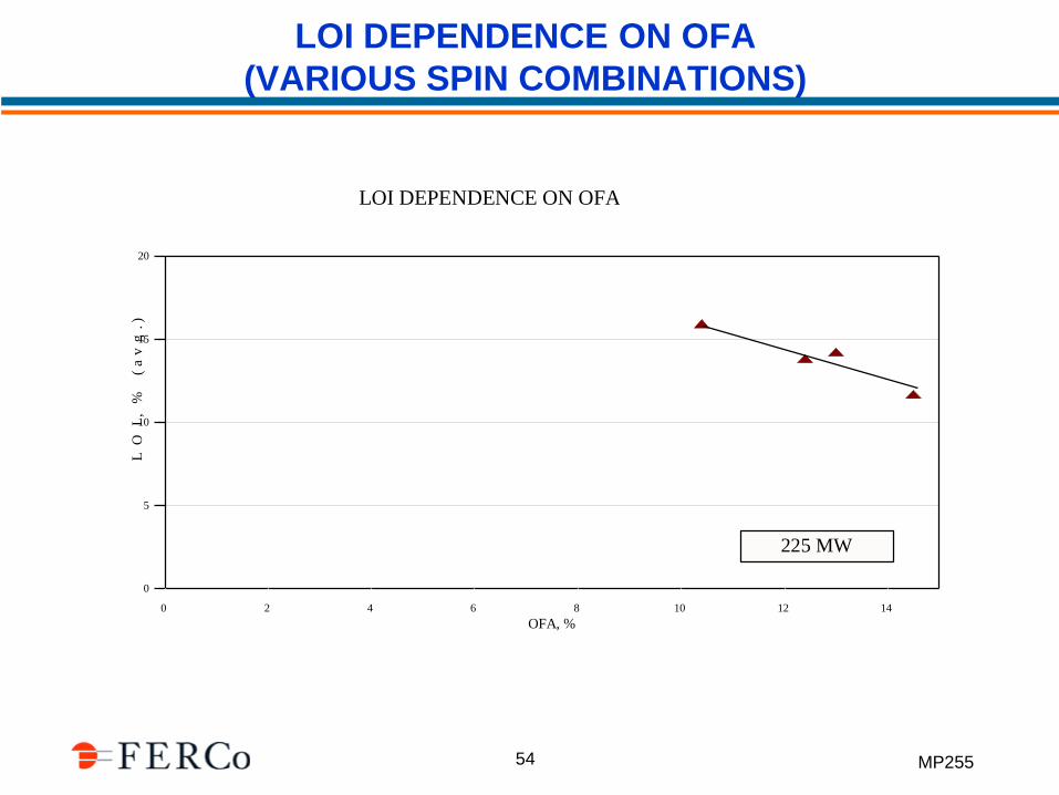
LOI DEPENDENCE ON OFA
(VARIOUS SPIN COMBINATIONS)
0
5
10
15
20
LO
I, %
(
av
g.)
0 2 4 6 8 10 12 14
OFA, %
LOI DEPENDENCE ON OFA (SPIN)D.E. KARN UNIT 2 - TUNE (2/2000)
225 MW
MP255 55
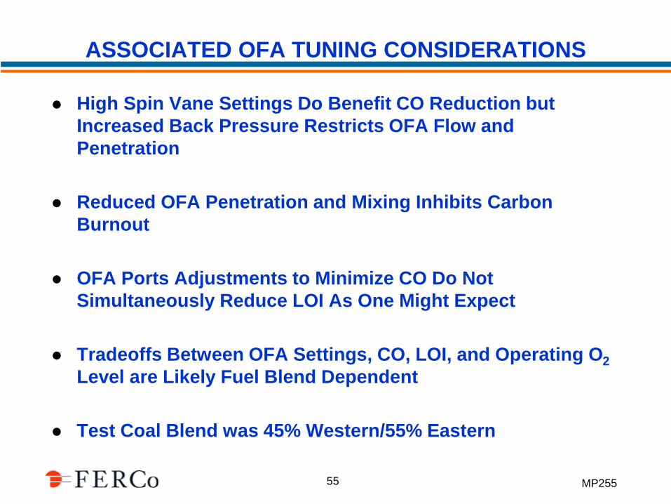
ASSOCIATED OFA TUNING CONSIDERATIONS
High Spin Vane Settings Do Benefit CO Reduction but
Increased Back Pressure Restricts OFA Flow and
Penetration
Reduced OFA Penetration and Mixing Inhibits Carbon
Burnout
OFA Ports Adjustments to Minimize CO Do Not
Simultaneously Reduce LOI As One Might Expect
Tradeoffs Between OFA Settings, CO, LOI, and Operating O2
Level are Likely Fuel Blend Dependent
Test Coal Blend was 45% Western/55% Eastern
MP255 56
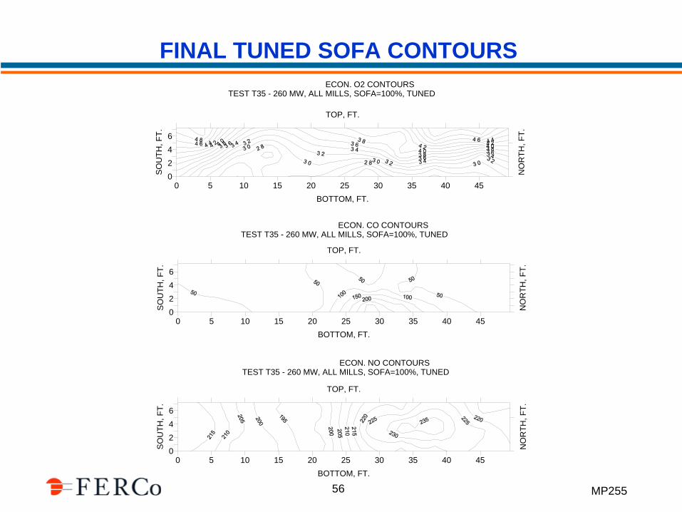
FINAL TUNED SOFA CONTOURS
0 5 10 15 20 25 30 35 40 45
BOTTOM, FT.
TOP, FT.
0
2
4
6
SO
UT
H, F
T.
NO
RT
H, F
T.
KARN UNIT 2 - ECON. O2 CONTOURSTEST T35 - 260 MW, ALL MILLS, SOFA=100%, TUNED
0 5 10 15 20 25 30 35 40 45
BOTTOM, FT.
TOP, FT.
0
2
4
6
SO
UT
H, F
T.
NO
RT
H, F
T.
0 5 10 15 20 25 30 35 40 45
BOTTOM, FT.
TOP, FT.
0
2
4
6
SO
UT
H, F
T.
NO
RT
H, F
T.
KARN UNIT 2 - ECON. CO CONTOURSTEST T35 - 260 MW, ALL MILLS, SOFA=100%, TUNED
KARN UNIT 2 - ECON. NO CONTOURSTEST T35 - 260 MW, ALL MILLS, SOFA=100%, TUNED
MP255 57
OTHER OFA TUNING ISSUES
Large Opposed Wall-Fired Boilers
– Two Elevations of OFA Better than One
– “Checkerboard” Pattern Enhances Mixing
Calibrated OFA Flow Measurement to each Elevation is
Important
“Compartmentalized OFA Windbox” Designs Can Provide
Added Flexibility
Resolve Burner Pipe Coal Flow Balance Issues Before
Tuning OFA
MP255 58
CONCLUSIONS
Balancing the Coal Flow Distribution to the Burners is an
Important Prerequisite to Burner Tuning
Fuel Rich Burners can Create “Hot Spots” of Incomplete
Combustion, Ash Deposits, Slagging/Fouling and Corrosion
Uniform Combustion is a Key Element in Efficient Low-NOx
Firing with Low-NOx Burners and OFA Systems
The Distribution of OFA Flow to the SOFA Ports is
Frequently Not Even on Retrofit OFA Systems
MP255 59
CONCLUSIONS (continued)
OFA Tuning is Often More Time Consuming Then Burner
Tuning to Achieve Optimum Combustion
Boiler and OFA Tuning Frequently Involves Adjustments to
Equipment that is Not Automatically Controlled
A Real-Time Multipoint Combustion Diagnostics Analyzer
can Reduce Boiler Tuning Test Time by a Factor of Three to
Five