Embed Size (px)
Citation preview
1
Tunnel Boring Machines used for Irrigation in Andhra Pradesh, India
D.Harding1
1The Robbins Company, Solon, Ohio, USA
1 INTRODUCTION The AMR project has been planned since 1983 and will provide irrigation facilities to drought-ridden areas in Andhra Pradesh. Water will be transferred from the Srisailam Reservoir during the monsoon months to 0.3 million acres of farmland and will also provide drinking water to villages en-route. The neighboring Veligonda tunnel is part of the Andhra Pradesh government’s Pula Subbaiah Veligonda Project in the drought-ridden district of Prakasam. The rainfall is low and erratic and does not sustain a subsistence crop. Local water use is from groundwater wells—a source which has become highly polluted from waste bacteria, and is now unfit for human or cattle consumption. Many people and cattle are affected with fluorosis for which there is no treatment. Once complete the system will draw 1.2 billion m3 of flood water annually from the foreshore of the Srisailam Reservoir. Up to 243 m3 of water per second will travel through the bored tunnel to a feeder canal. From there, the water will be distributed through a network of five canals to over 400,000 acres of land in the three districts of Prakasam, Nellore and Kadapa. This paper will address the design and planning of the use of three Double Shield TBMs for the excavation of both AMR and Veligonda tunnels-- part of a large irrigation scheme by the Andhra Pradesh government. The paper will also provide a current status of the projects and describe the advantages of onsite assembly, problems encountered to date, and the solutions adopted. 2 ALIMINETI MADHAVA REDDY PROJECT (AMR) 2.1 Project Description. The AMR Project was awarded to the Main Contractor Jaiprakash Associates Ltd with The Robbins Company supplying the TBMs, two continuous conveyor systems, all spares and consumables, and operating personnel to complete the tunnel excavation. The tunnel is altogether 43.9 km in length and will be excavated using two TBMs, one each starting from either end. The project is exceptional because there is no possibility of intermediate access along the 43.9 km alignment, making this currently the longest bored TBM tunnel to be constructed in the world. Two new 10 m bore tunnel boring machines were chosen by Jaiprakash, to have any prospect of completing the project in the required 60 months. The TBMs are able to install a segment final lining simultaneously with excavation. Each tunnel drive is planned at 22 km each and is carried out from the respective excavated portal areas at the outlet end and inlet end. Portal surface areas were maximized so that the full length of the TBM could be assembled for ease of launching the machine. This was straightforward for Jaiprakash at the outlet as they had no space limitations and the portal was designed to be 45 m wide and 160 m long. But at the inlet because excavation of the portal area was known to be far more challenging, the portal area had to be reduced to 120 m by 45 m and protected by a bund wall, as the site is below the FWL of the reservoir.

2
Excavated spoil from the tunnels is transported by a continuous csystem from the TBM to the surface spoil handling area where trucks are loaded to move material to spoil dumps. The excavated granite, from the outlet TBM drive and from the portal excavation, is being recycled for use as concrete aggregate and pea gravel by Jaiprakash. The same is planned at the inlet where the quartzites also make good aggregate. 2.2 Site Investigation and Geology. The geology of the tunnel has been interpreted mainly from surface mapping and aerial photography. Jaiprakash had completed walkover of the surface and survey of all river valleys above the tunnel. One such steep valley affected the tunnel and resulted in the realignment of the project. The geology is generally very stable as it is part of the ancient South Indian Peninsular Shield, which consists of two main rock types: quartzites and granite. Normal rock properties of Srisailam quartzites
• Density 2.53 to 2.80 g/cm3 • Compressive strength 850 to 2,650 kg/cm2 (83 to 260 MPa)
Normal rock properties of granites • Density 2.62 to 2.86 gm/cm3 • Compressive strength 1,000 to 23,00 kg/cm2 (98 to 225 MPa)
From tunnel chainage 0 m at the inlet portal to tunnel chainage 26,450 m ground consists of quartzites and thin interbedded layers of shale. From tunnel chainage 26,450 m to the outlet portal at tunnel chainage 43,950 m a length of 15,500 m of granite will be encountered (refer to Figure 1). The expected proportion of quartzite to granite depends on the orientation of the granite to quartzite transition currently projected from geological mapping carried out on the surface.
Figure 1. Geological section The quartzites, over 60% of the tunnel, are metamorphic and have very high quartz content. Their significant abrasiveness and high strength give the most concern for cutter wear and costs. The expected physical properties of the rocks are given above. Results from tests carried out on the quartzites and from information at the Srisailam power station have shown that compressive strengths of the quartzite can go as high as 4,588 kg/cm2 (450 MPa). The quartzite section also can be very blocky in nature and includes thin and weak interbedded shales. The layering of quartzite and shales will tend to cause over break in the crown and shoulder of the tunnel.The granites for 40% of the tunnel are generally expected to be consistent in nature and are less cause for concern. 3 VELIGONDA PROJECT
3
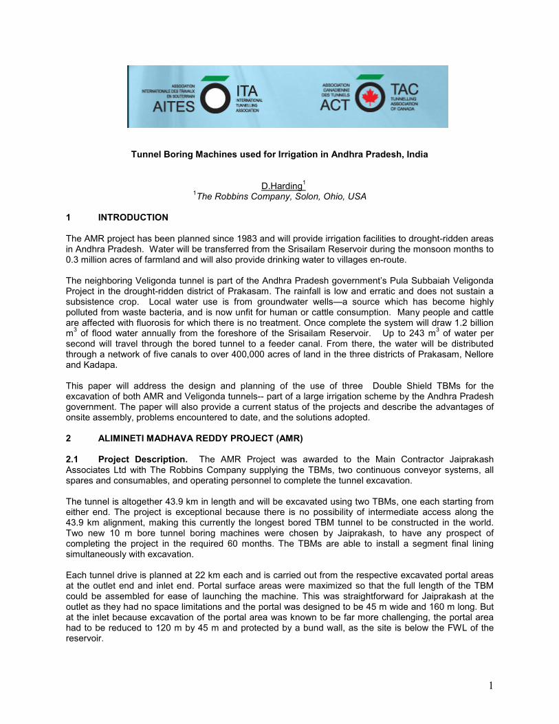
3.1 Project Description. The USD $180 Million contract was awarded to Hindustan Construction Company (HCC) / Coastal Projects Pvt. Ltd. JV. In October 2007, the TBM and continuous conveyor system, all spares and consumables parts, and key operating personnel were sent to the jobsite. The salient features of the Veligonda Tunnel II are very similar to the AMR project apart from the length of the tunnel being only 19.2 km. The TBM used on the Veligonda Project is nearly identical to the Double Shields used on the AMR Project and incorporates the same specifications and features. The bore diameter and segment diameters are identical at 10.0 m and 9.2 m respectively. The design of the segmental lining is also identical to the AMR Project. 3.2 Site Investigation and Geology. As with the AMR project the geology of the tunnel has been interpreted mainly from surface mapping. Satellite imagery has also been used. The area encompassing the tunnels is formed of sedimentary rock of the western margin of the Cuddapah basin. The sedimentary rock here belong to Kollamu Vagu shales and quartzite’s and Cumbum slates and quartzites The geology of this area is rather complex with a number of faults and folds affecting the formations. The Kollamu Vagu stream is structurally controlled and runs along a major fault. The entire length of Kollamu Vagu was re-contoured to study the geology, structural features and select a suitable site for the Inlet Portal of the tunnel. The whole of the Veligonda tunnel II geology (see Table 1) has been given an expected RMR value of between 61 and 75 which remains firmly within the Rock class II category. Major faults are expected at chainages 1,350 and 14,200 where water seepage is expected along the fault plane.
Table 1. Veligonda Geology SI
No. Anticipated % in
Tunnel Rock Type & Characteristics RMR Class Expected
1 10% (950 m) Srisailam Quartzite with interbeds of Shale
73 (Class II: Good
rock)
2 40% (4,050 m) Cumbum Shale with minor
quantity of Phylite and/or lenses of Shaley Limestone
68 (Class II: Good
rock)
3 50% (8,200 m) Cumbum Quartzite with interbeds of Shale.
73 (Class II: Good
rock) 4 TBM CHOICE Double shields were eventually finalized as the best choice for the tunnel excavation by both contractors after detailed discussion and analysis. Discussions of using Open type TBMs, or a combination of Open type and shielded type machines, were considered; however, Double Shield machines were considered the simplest solution. Three 10 m High Performance type (H.P.) Double Shield TBMs with identical features were supplied : wo for the AMR project and one for the Veligonda project. The main reasons for the choice of Double Shield machines were:
• Erection of segment lining simultaneously with excavation • Majority of the tunnels in very blocky and layered shale and quartzite • No temporary support required • Temporary support difficult to quantify and estimate • Concrete lining after excavation or in parallel with excavation eliminated • Optimum program with no delay in follow-on concrete lining • Various fault and shear zones expected • Hydraulic design requiring a lining

4
5 TBM DESCRIPTION AND MAIN DETAILS 5.1 Cutterhead. The cutterhead consists of a six-piece bolted and doweled heavy duty structure for hard rock (see Figure 5). The cutterhead is made from heavy steel plates, internally reinforced with integral buckets to remove the rock cuttings. The buckets pick up spoil and deliver it by gravity to the central TBM conveyor situated within the cutterhead support. The total weight of the assembled cutterhead is in excess of 300 tonnes. 20-inch diameter cutters were supplied for the high cutter loading and increased wear resistance over the 17” or 19” types. The use of 20” rings allows an additional 80% of rim material for wear and gives additional cutter life of about 20% over 19” rings.
Figure 5. Cutterhead front view
5.2 Main Bearing, Seal and Ring Gear. The main bearing assembly is a Hard Rock type Tri-axis bearing with separate ring gear. The high capacity main bearing accepts both the radial and thrust loadings associated with the cutterhead operation. The ring gear is separate from the bearing and is an externally toothed gear mounted to the cutterhead adaptor and secured in place by studs, hex nuts and washers. An inner and outer seal is mounted to the non-rotating structural components with the lips of the seals providing sealing action against the rotating components. The seals are oriented so that the lips prevent entrance of contaminants into the cavities of the bearing. Dimensions of the shields and layout of the components described above are given in Figure 6.
Figure 6. TBM shields and layout
7 CONVEYOR SYSTEM

5
The conveyor system in itself is a major component of the tunnel. Each system has been designed for an operating length of the complete tunnel and is VFD controlled. Figures 10 and 11 shows the portal loop cassette, the incline conveyor and stacker. Specifications of the conveyor are:
• Drive unit – 2 X 300 kW • Booster unit for 11,250 m – 2 X 300 kW • Belt capacity – 800 TPH • Belt speed – 3.0 m/s • Belt width – 914 mm • Cassette capacity – 600m
Figure 10. Loop cassette at portal Figure 11. Incline and stacker conveyor 8 SEGMENT DESIGN AND PEA GRAVEL INJECTION Segment design, reference figure 12, consists of a 1.6 m length segment and a 6+1 element ring. The segment was designed with reinforcing of 95 kg/m3 and ring thickness of 300 mm. The ring is bolted parallel sided, with no taper, with no gasket. Specification summary of the ring is given in Table 2.
Table 2. Summary of segment lining
The invert segment has external supporting pads cast onto the extrados which allows the segment to be placed directly onto the invert. In each segment there are two erector shear pin holes, with one of these being used for pea gravel injection and grouting purposes. Additional grout holes are also available in the invert and lower two segments. The full ring weighs some 40 tonnes, with the flat invert segment just below 10 t in weight.

6
Pea gravel is injected from the back-up to the front segment rings. Injection through the segments, on rings 2 and 3, has proven to be most successful in filling the annulus. Two Aliva 263 pumps are used to give more than 200% of the necessary injection capability. Pea gravel is produced on site from crushed and screened muck produced by the excavator. Grouting is carried out initially to securely bed the invert segment as the first stage and then some 40 ring back to fill any voids left in the pea gravel and in the crown of the tunnel. Two sets of grouting equipment, one for each stage, are mounted on the back-up system. 9 ONSITE ASSEMBLY All three machines were planned to be delivered in a very short time frame. The first components of the TBMs were to be shipped within eight months of finalizing the order. Due to the very short start up program required for all three tunnels, the “Onsite First Time Assembly” (OFTA) supply method was adopted. Under this supply, components from the various manufacturing plants and sub-contract locations are brought to site, and assembled together at the project site. Individual major assemblies such as the main bearing, shield assemblies, segment erector, hydraulic power packs, and electrical packs were pre-assembled and tested at facilities prior to shipment to site. Shipping dates as required under the contract were successfully achieved using the OFTA process. Time savings were estimated to be some 4 to 5 months, and there were significant cost savings in shipping and handling compared to a full factory assembly. 10 PROJECT STATUS The AMR (outlet) machine started the commissioning and excavation of the tunnel during May 2008 and, as of December 2009, had bored approximately 6 km of tunnel with an approximate monthly average to date of 350-400 m. The Veligonda machine started the commissioning and excavation of the tunnel during August 2009 and had bored approximately 750 m of tunnel with an approximate monthly average to date of 150-200 m. The second AMR (inlet) machine, although mostly delivered to site during 2007, had just begun being assembled in July 2009 because of the considerable problems that were encountered in obtaining access to land necessary for the inlet portal. The machine and back-up were assembled and ready for launch in September 2009, when a 100 year monsoon hit Andhra Pradesh. The monsoon soon filled the reservoir with water and breached the retaining wall thus flooding the machine and back-up. The equipment is being re-built due to this flood. Production outputs to date for the TBMs have been improving. Excavation outputs on a monthly basis are noted below in Figure 13 and 14 for AMR Outlet and Veligonda, respectively.

7
Figure 13. Monthly production AMR Outlet
Figure 14. Monthly production Veligonda
11 PROBLEMS ENCOUNTERED AND ADOPTED SOLUTIONS
11.1 One Hundred Year Monsoon. A major problem occurred on October 2, 2009 at the AMR Inlet, when the jobsite was hit by a 100 year monsoon which flooded the jobsite and covered the TBM and back-up. The natural coffer dam wall at the inlet site was not designed to withstand a major flood, and was breached by the flood waters. Flood control doors were not opened in time to release the water downstream, causing the significant rise in water levels. The equipment was under water for approximately ten days until the water was pumped out. Currently the equipment is being completely refurbished by Robbins personnel at the jobsite.
Figure 15. AMR Inlet pre-flood Figure 16. AMR Inlet post-flood Figure 17. Recovery of machine

8
11.2 Rock Blocks Damaging the Conveyor. The AMR Outlet project faces conditions that are extremely blocky, giving rise to large blocks making their way thru the front of the cutterhead. These conditions were not expected given the geology, as it was anticipated that the rock would be cut into smaller pieces by the action of the cutterhead. During excavation, rock blocks often managed to pass through the muck buckets and end up on the conveyor belt. Early on, these blocks would stop in transfer hoppers and point load the conveyor belt, causing massive tears in the belt. Blocks also rolled back and dropped off the incline and stacker conveyor. The solution proved to be in reducing the spacing of grizzly bars on the muck buckets and adding additional bars so the boulders could not pass onto the conveyor system (see Figures 18 and 19). Grill bars were additonally added to the AMR Inlet machine and also to the Veligonda machine prior to the start of boring. The installation of the grill bars reduces the effective bucket opening, meaning that in soft or mixed geology the buckets are more susceptible to becoming plugged. In good ground, the grill bars are removed to allow a higher, more even flow of material into the muck/hopper chamber.
Figure 18. Boulders! Figure 19. Installing grizzly bars on muck buckets
11.3 Power Outages. Each site is meant to run from a main electricity supply (per site) but does have full generator back-up. Regular power outages occur, which cause sudden stops to boring. In some weeks up to 30 power cuts have been recorded. To date, no solution for this problem has been found as the power grid in the area is weak and additional investigation by the Power Authority is being reviewed. 11.4 Pea Gravel Injection. It was initially planned to inject pea gravel on all three tunnels, from rings 6 and 7, some 10m from the tail shield. This assumed that pea gravel would flow in the annulus outside the segment lining. This proved not to work and pea gravel injection had to move right up to ring 2, almost at the tail shield itself. The pea gravel manufactured from crushed granite and even tunnel spoil is coarse and not ideal. In addition to excessive wear caused by the gravel it certainly doesn’t flow properly outside the segments. This was because natural ‘round’ pea gravel was not available, so crushed aggregate was introduced as an alternative. 11.5 Local Labor Force. The local Indian labor force is not experienced in TBM work –this was to be expected but training and gaining experience did lengthen the learning curve process. It must be said that although generally inexperienced, the workforce has been keen and very willing to learn. To help cope with the learning curve, a detailed training course was put together, which takes the contractor’s personnel through four stages of learning, from general tunneling to studying the operation and maintenance manuals of the equipment. 12 CONCLUSIONS
There are a number of solutions to the problems encountered at the AMR and Veligonda jobsites. Grill bars were installed at the cutterhead muck bucket openings of all three machines to anticipate the large rock blocks currently being encountered in the AMR outlet tunnel. In addition, diesel gen sets at all of the job sites may help to alleviate problems due to frequent power outages, by allowing critical operations to continue. In the case of flooding during India’s rainy seasons, a more prudent plan by local power company operators needs to be developed, so that there is a plan for flood control at Srisailam Dam.


![Untitled-1 [] · Nagarjuna Sagar Dam õ3NãgerjunasagaóSite Jammar . ANDHRA AUTHORITY . ANDHRA AUTHORITY . ANDHRA AUTHORITY . ANDHRA AUTHORITY . ANDHRA AUTHORITY . ANDHRA AUTHORITY](https://img.pdfslide.net/doc/110x75/5fa86894420206628339e79d/untitled-1-nagarjuna-sagar-dam-3ngerjunasagasite-jammar-andhra-authority.jpg)