Embed Size (px)
Citation preview

TUNNEL
PASTEURIZER
Use and maintenance instructions
MarkingTMCI Padovan s.p.a.via Dal Vera 13 - 31015 Conegliano (TV) - ITALYtel. 0438-4147 fax. 0438-23682
Serial Nr. : 91200046-0/001
Year of supply : 2000
Ref. Contract dd. 12-01-2000
TUNNEL PASTEURIZER - Cat. 2000-05-5646

page 1 TUNNEL PASTEURIZER CAT.2000-05-5646
INSTRUCTIONS FOR USE AND MAINTENANCE OF TUNNEL PASTEURIZER
INDEX Page
- TECHNICAL DATA 2
1) GENERAL SAFETY RULES 4
1.1) General information 4
1.2) Equipment of personnel 4
1.3) General mandatory instructions 4÷5
2) INSTALLATION RULES 6
2.1) Unloading from transport means 6
2.2) Control of delivery and assessment of
any damage 7
2.3) Temporary storage 7
2.4) Installation of transmission shaft and
countershaft 8
2.5) Belt Installation 8
2.6) Installation of conveyor belts and head
fairing 9
2.7) Piping and accessories 10
3) CONNECTIONS 11
3.1) Electrical connections and controls 11
3.2) Earthing 11
3.3) Steam connection 11
3.4) Condensate connection 12
3.5) Exhaust steam connection 12
3.6) Water connection 12
3.7) Water draining 12
3.8) Plate-Type exchanger connection (optional) 13
4) REGULATIONS 14
4.1) Thermoregulation device 14
4.2) Inlet and outlet conveyor belts 14
4.2.1) Belt lubrication 14
4.2.2) Regulation of belt speed 14
4.3) Regulation of safety limit switches 15
4.3.1) Limit switch control before starting 15
Page
5) CHOICE OF OPERATION CYCLE 16
5.1) General principles 16
5.2) Variations of pasteurization cycle 16
5.3) Variation of heating cycle 17
- Table 1 (Relationship between tempera-
ture and lethality potential and pasteurization
unit by minutes of treatment) 17
6) PLANT OPERATION 18
6.1) Starting the plant 18
6.2) Standard operation 19
6.3) Stopping the plant 19
- Table 2 (Lubrication) 20
7) ELECTRIC SWITCHBOARD 21÷27
8) SPARE-PARTS LIST 28
ENCLOSURES :
- Dwg.No. 771-133 (Wiring diagram)
- Dwg.No. 060-148 Rev.1 (P. & I.)
- Dwg.No. 060-149 Rev.1 (Assembly drawing)
- Dwg.No. 066-082 (Exchanger drawing)
- Use, maintenance and exploded view of
appliances composing the plant (pumpes, etc..).
- Dwg.No. SP060-149, Dwg.No. 060-134

page 2 TUNNEL PASTEURIZER CAT.2000-05-5646
TECHNICAL DATA
? AS A HEATERBottles treated: n°/h 8.700Diameter: mm 62Treatment time: mins. 36Bottle inlet temperature: °C 2
? TREATMENT TEMPERATUREBottle inlet temperature: °C 2Heating from 2°C to 17°C with water at: °C 23Heating from 17°C to 32°C with water at: °C 38Heating from 32°C to 62,5°C with water at: °C 67,5Holding at 62,5°C with water at: °C 63Cooling from 62,5°C to 47°C with water at: °C 36Cooling from 47°C to 32°C with water at: °C 21Bottle outlet temperature: °C 32UP: 28,6
? TREATMENT TIMEHeating: mins. 15'Holding at pasteurizing temperature: mins. 11'Cooling: mins. 10'
----------- ------------Total cycle time: mins. 36'
? CONSUMPTIONSteam consumption at start: kg/h 480Steam consumption in operation: kg/h 280Air consumption: Nl/h 1.500Frigorific consumption: btu/h 300.000 a +5°C
? CONSTRUCTIONS FEATURES
Tunnel elements- number: n° 1- total length: mm 8.800- total width: mm 2.140
Total pasteurizing surface: m2 18,85
No. of water circulation pumps: n° 7
No. of conveyor belts:- at inlet: n° 1- at outlet: n° 1

page 3 TUNNEL PASTEURIZER CAT.2000-05-5646
P U M P S
Nr. 6 WATER CIRCULATING PUMPS Code 46223611Type : centrifugal - Model DWO 3006
Material : Stainless steel Aisi 304
Motor : 2 poles type - 2,2 kW
Nr. 1 WATER CIRCULATING PUMP Code 46223613Type : centrifugal - Model DWO 4006
Material : Stainless steel Aisi 304
Motor : 2 poles type - 3 kW

page 4 TUNNEL PASTEURIZER CAT.2000-05-5646
1) GENERAL SAFETY RULES
1.1) GENERAL INFORMATION
TMCI Padovan pasteurizers are equipped with some safety devices that meet specificdirectives and rules.However, the operator is reponsible for making sure that the general standards and rulesand special safety indications are strictly respected when handling and maintaining thesystem.
1.2) EQUIPMENT OF PERSONNEL
The operators and maintenance personnel must wear a plastic visor on the head, insulatedgloves because of high temperature steam piping, protective gloves and boots duringcleaning operations.
1.3) GENERAL MANDATORY INSTRUCTIONS
- If it is necessary to carry out any operations on the bottle outlet belt, protect face andhands as described above.
- IMPORTANT!! - Close the main switch before opening the electric switchboard orcarrying out any operations on motors or electrical connections.
- Make sure that the system has been earthed appropriately.
- Close the main switch before performing any operations on any parts in movement(conveyor belts, advancement surfaces, pumps).
- Do not put hands or objects held with hands in areas where there are moving parts.

page 5 TUNNEL PASTEURIZER CAT.2000-05-5646
- Do not sprinkle the electric switchboard, motors or electrical connections with wateror other liquids.
- Follow the general safety rules when washing the tunnel periodically with acid or basicdetergent solutions. Remember to use protective gloves and glasses.
- When handling caustic soda, remember that it develops a great amount of heat whensoda is dissolved in water.
- If operations have to be carried out on parts subject to steam pressure or hot water(piping, regulation valves, tube nest heat exchangers), make sure that the steam orwater cutoff valves are closed, that the parts involved have been drained and that theyhave reached acceptable temperatures.
- If you are operating on components subject to heating, make sure that they havereached a temperature tolerated by the operator. If necessary protect hands withspecial gloves.
- When handling containers (especially glass bottles) containing pressurized liquids,remember not to open the tunnel’s inspection doors during use. The danger ofexplosion in this containers grows as the temperature rises because the latter makesthe inner pressure increase.
- During the process some containers may break inside the tunnel; the broken glassmust be removed periodically from the vats or from the advancement surfaces. Theoperator must perform these operations carefully and protect hands with appropriategloves.
page 6 TUNNEL PASTEURIZER CAT.2000-05-5646
2) INSTALLATION RULES
2.1) UNLOADING FROM TRANSPORT MEANS
Tunnel pasteurizers are generally delivered divided as follows:
- modular elements including metal structure, a part of the distribution piping, pumps,filters;
- accessories such as conveyor belts, electric switchboard, head fairing, etc.
The modular elements must be unloaded and positioned on site using self-propelled oroverhead cranes.
Each tunnel has a special fastening frame onto which cables must be fixed to the specialfittings.
The frame is only one and must be used to lift one unit at a time. Make sure that the craneand the manouevring equipment can bear the weight of each element.
If the elements are packed, pass the cables under the packaging at the indicated points.
Lift the elements according to the above-mentioned instructions to take them out of thepackaging.
In order to take the elements out of the container, fasten the cables to the indicated pointsand pull the element carefully outwards. When the unit protrudes sufficiently, fasten thecables and proceed as above.
WARNING !!
Never lift the elements using unappropriate hoisting means, such as fork lift trucks;once the unit has been placed on the ground, never push it around.
When cables are used for hoisting, once they have been pulled tightly make sure thatthey do not scrape against delicate components.
Lift each element about 50 mm and make sure that it is perfectly balanced. Balancing canbe achieved by adjusting the cable on the frame.
Do not cause abrupt movements of the equipment.
During these operations be careful that the equipment does not knock abruptly on the floor.
Use the same attention when unloading and moving the accessories so that no parts aredeformed or damaged.

page 7 TUNNEL PASTEURIZER CAT.2000-05-5646
2.2) CONTROL OF DELIVERY AND ASSESSMENT OF ANY DAMAGE
Control all the goods upon arrival and make sure that all the components listed in the deliverynote or packing list are in perfect conditions.If some parts are missing, if the crates or packaging have been tampered with or goods aredamaged, it is necessary to write out a report, have it signed by the forwarding agent andnotify the insurance company immediately.Notify the insurance company even in case of damage occurred during unloading,displacement and positioning.
If the insurance it at TMCI PADOVAN’s own expenses, advise the company immediately bytelex or fax and wait for instructions.
Any rights to damage indemnification are forfeited if TMCI PADOVAN is not notifiedimmediately.
Do not remove protections or locking devices until installation, unless there are clear signsof damage.Put covers back into position if the goods are going to be stored for some time.
Crates which have been opened for inspection must be handled with care to preventdamaging contents; pack the parts again and store in a safe place until it is time for assembly.
Please refer to STORAGE for information concerning how to handle these units.
2.3) TEMPORARY STORAGE
If the tunnel is not placed immediately in the final installation position, store it in dry and well-aired premises at a minimum temperature of +10°C.
Cover all surfaces subject to oxidation and corrosion with a suitable protection.
Control frequently any signs of oxidation, especially on machined or uncoated surfaces(shafts, bearings, etc.).Remove the oxidation or any signs of corrosion immediately and apply an appropriateanticorrosion protection over the damaged surfaces.
Rubber parts must be protected against very low temperature and should never be storedoutdoor even for very short periods. Keep rubber parts well-aired if the environment is warm.
In case of prolonged storage or inactivity after a first startup or a considerable delay instarting up the system after delivery, it may occur that some gaskets or seal rings hardencausing leakages or seizures.
page 8 TUNNEL PASTEURIZER CAT.2000-05-5646
The greases or lubricants used to install the bearings, shafts, etc. may also harden.
Therefore in these cases (inactivity lasting over 6 months), it is necessary to control the entiremachine, replace all the gaskets or parts that may deteriorate during storage or inactivity.
These operations require qualified and authorized personnel to prevent that badly performedoperations or incorrect reassembly may damge the appliance when operation begins again.
IMPORTANT !! Make sure that:
- there is no water in the vats, in the tanks and in the pumps; leave the drains or tapsopen;
- there are no iron objects in contact with stainless steel components;- there is no dripping from iron structures;- there is no possibility of damaging components caused by equipment in transit, goods
or people close to the plant.
2.4) INSTALLATION OF TRANSMISSION SHAFT AND COUNTERSHAFT
Once the units have been positioned, install the transmission shaft (to which the motor-driving unit has been installed) and the countershaft.
They are both fitted on appropriate supports that must be fixed to the end of the tunnel.
It is important to make sure that the central support of the transmission shaft (only on largepasteurizers) is installed correctly.
2.5) BELT INSTALLATION
Arrange the roll/s in front of the tunnel (bottle inlet side) with the ends of the tube, that passesthrough the middle of the roll, on special supports.
Make some ropes pass under the transversal bars supporting the belt and above the rollerssupporting the belt return.
page 9 TUNNEL PASTEURIZER CAT.2000-05-5646
Tie the ropes to an iron rod and then tie the latter with several wires to the belt’s first bar.
Pull the ropes slowly from the end of the bottle outlet and push the belt inside the tunnel.
When the belt reaches the transmission shaft, roll up its end around the gears and reversethe ropes right up to the bottle inlet head.
It is now possible to make the transmission shaft turn with the belt end connected by meansof the gearmotor. At this stage it is necessary to keep the end of the bel stretched with theropes, stop the gearmotor when the end of the belt comes out of the tunnel. Detach theropes and whatever else from the belt and join the two pieces keeping the belt welltensioned. Insert the connecting bar and fix the end nut.
After this operation it is advisable to start the belt at full speed and make it turn for 4-8 hoursto control operation and stability.
Control that the return of the belt is supported appropriately and does not scrape over anysurfaces of the lower vats, but is supported by the lower rollers.
2.6) INSTALLATION OF CONVEYOR BELTS AND HEAD FAIRING
The inlet and outlet belts can be delivered already assembled to their fairing or be suppliedseparately.
If they are separate, it is necessary to fix them to each fairing with the front screws and motor;then fix the fairings and belts to each end of the tunnel with the perimeter screws, insert theupper tie rods supporting and regulating the belt height and then insert the lateral screwsto fix the belts to the heads.

page 10 TUNNEL PASTEURIZER CAT.2000-05-5646
2.7) PIPING AND ACCESSORIES
Once the tunnel has been installed, fit the pump connection piping to each area, the steaminlet pipes in the heat exchangers with the regulation valves, the condensation and manifolddrain pipes.
We recommend to carry out these operations according to the plant’s technologicaldiagram.

page 11 TUNNEL PASTEURIZER CAT.2000-05-5646
3) CONNECTIONS
3.1) ELECTRICAL CONNECTIONS AND CONTROLS
- The tunnel is supplied with electrical connections between the switchboard and themotors and control instruments. It is sufficient to connect the cable terminals on theswitchboard according to the diagrams included and connect the electric switchboardto the mains.
- Control that the connection teminals on the motors are tightened firmly (the vibrationsduring transport may unloose the terminals or even disconnect the cables).
- Control that the power supply and the electrical features of the machine are equivalent.
- Connect the electric switchboard with a four-pole cable (three phases + earth) andplug to a socket with switch and fuses.
- Control that the diameter of the feed line is sufficient for the working and starting load.
- Control that the direction of rotation of the motors is equivalent to the data platefigures installed on the motors.Control the pumps only for a few seconds to avoid damaging the rotary seals.
3.2) EARTHING
- Connect the earth plate on the tunnel to the earth line with an appropriate size cable.
3.3) STEAM CONNECTION
Connect the flanged fitting to the steam feed piping.The piping must have a suitable diameter to ensure that pressure and output are suitablefor the plant’s requirements.If the pressure is greater, it must be reduced by fitting a pressure reduction unit.The feed steam must not contain any condensate; the feed piping must be insulated andequipped with a steam trap, if necessary.

page 12 TUNNEL PASTEURIZER CAT.2000-05-5646
3.4) CONDENSATE CONNECTION
When heating is achieved by steam condensation in tube nest heat exchangers,m themanifold fitting must be connected to the piping for the return to the boiler.
The return to the boiler can be made directly, if the distance and different boiler level allowit, or using a pump.
3.5) EXHAUST STEAM CONNECTION
Fittings dia. 200 mm can be available on the tunnel covers near each end.
If these fittings exist, they can be connected to the outside of the building using stainlesssteel or stiff plastic tubes.
3.6) WATER CONNECTION
Connect the fitting to the water supply piping coming from the water mains.This pipe must have a suitable diameter to ensure a proper water output and pressure asshown in the technical chart.
3.7) WATER DRAINING
The vats are equipped with an overflow drain that eliminates any excess of water during use.At the end of the process, drain the vats and wash them with jets of water.The drain water must be collected in a drain channel made in the floor.

page 13 TUNNEL PASTEURIZER CAT.2000-05-5646
3.8) PLATE-TYPE EXCHANGER CONNECTION (OPTIONAL)
In some case, to reduce water consumption in the cooling section, a plate type exchangeris applied: such device allows to lower water temperature in the final section by means ofglycol solution.The connection piping diameter must be suitable for the foreseen fittings.

page 14 TUNNEL PASTEURIZER CAT.2000-05-5646
4) REGULATION
4.1) THERMOREGULATION DEVICE
The temperature of water in the pasteurizer sections can be adjusted in one of the followingthree ways:
I) Using special tube in tube heat exchangers placed on the water circuit, that keep theset operating temperature in the plant’s different sections by means of a pneumaticvalve controlled by a special thermoregulator.
II) By means of steam injectors inside some vats or on the delivery side of some pumps.In this case the water temperature is controlled by thermostats that control the steamcutoff solenoid valves..
III) By means of a plate-type exchanger, with coolant, for the cooling phase.
4.2) INLET AND OUTLET CONVEYOR BELTS
4.2.1) BELT LUBRICATION
The tunnel’s inlet and outlet belts need to be lubricated continuously so that that thecontainers slide over them without tipping.Spray on each belt special liquid lubricants that are available on the market or, if they cannotbe found, using a soapy solution.
Spray the solution over the surface of each belt in the area not involved by the movementof the containers.
The centralized system of the bottling line can be used for lubrication or an independent unitprovided with a tank and dosage pump.
If the belts are provided with an inner lubrication vat, make sure that the level is alwayssufficient for the belts to be dipped in the lubricant.
4.2.2) REGULATION OF BELT SPEED
The inlet and outlet belts are two or more; they all have a speed that allows a capacity ofapproximately 10% more than the tunnel’s own capacity and they can be driven by agearmotor with fixed reduction ratio or by a ratiomotor.

page 15 TUNNEL PASTEURIZER CAT.2000-05-5646
A limit or proximity switch is installed at the end of the outlet belt.
When the movement of containers after the tunnel is interrupted, the containers fill the outletbelt completely.
The pressure of the containers makes the limit switch operate and it stops the advancementof tunnel surface.
4.3) REGULATION OF SAFETY LIMIT SWITCH
A safety limit switch is installed on the belt movement unit near the torsion bar of thetransmission shaft. It is extremely important for the integrity of the tunnel belt.
This safety device blocks the belt in case of belt overloading or clogging, caused by brokencontainers inside the tunnel.
The belt can be started again only from the electric switchboard and once the cause of theoverload has been eliminated.
4.3.1) LIMIT SWITCH CONTROL BEFORE STARTING
Before starting the plant for the first time or after long periods of inactivity, we recommendto carry out the following operations:
- Unloose the lock screws on the torsion bar of the transmission belt’s ratiomotor.
- Start slowly. The limit switch will operate and stop movement because the screws havebeen unloosed.
- Tighten the screws a little and repeat the operation until movement is continuous.
- Place the containers. If the belt should stop, tighten the screws again until the belt withall the containers move safely and constantly.

page 16 TUNNEL PASTEURIZER CAT.2000-05-5646
5) CHOICE OF OPERATION CYCLE
5.1) GENERAL PRINCIPLES
The kind of treatment cycle is established when designing the tunnel according to:
- length and number of stages for heating phase,- holding time and temperature for pasteurization phase,- time and number of stages for cooling phase.
The number and time of heating and cooling phases are established according to:- type, volume and resistance to heat shocks of containers,- energy recovery.
The pasteurization time and temperature are established according to:- containers temperature resistance,- number of pasteurization units required.
A PU pasteurization unit is the pasteurization result achieved by holding a product at 60°Cfor one minute.
The enclosed table (1) provides a list of the different PU according to the treatmenttemperature.The total pasteurization effect of a cycle is calculated by multiplying the PU of thepasteurization temperature by the holding time and adding the pasteurization effectachieved in the heating and cooling phases.
5.2) VARIATIONS OF PASTEURIZATION CYCLE
The length of each area in which the tunnel is divided for heating, holding and cooling isfixed, and so are the ratios between the travelling time of the containers in each area.
The following values can be changed:
Total treatment time - Adjust the speed variator of the belt advancementunit manually.
Pasteurization temperature - Operating on thermoregulators set-points ofheating, pasteurizing and cooling vats.

page 17 TUNNEL PASTEURIZER CAT.2000-05-5646
TEMPERATURE
(°C)
4646.54747.54848.54949.55050.55151.55252.55353.55454.55555.55656.55757.55858.55959.56060.56161.56262.563
TEMPERATURE
(°C)
63.56464.56565.56666.56767.56868.56969.57070.57171.57272.57373.57474.57575.57676.57777.57878.57979.58080.5
LETHALITY PO-TENTIAL AND UP
0.010.0120.0140.0160.0190.0230.0270.0320.0370.0450.0520.0620.0720.0860.10.120.140.160.190.230.270.320.370.450.520.620.720.8611.21.41.651.92.32.7
LETHALITY PO-TENTIAL AND UP
3.23.74.55.26.27.28.610121416.519232732374552627286100119139166196231268320373445519620720860
TABLE 1
RELATIONSHIP BETWEEN TEMPERATURE AND LETHALITY POTENTIAL ANDPASTEURIZATION UNIT BY MINUTES OF TREATMENT
5.3) VARIATIONS OF HEATING CYCLE
In this case, the different stages of the tunnel pasteurizer operate as a single stage, so as toreach the thermoregulators set-point temperature.Even in this case it will be possible to adjust the treatment time for the bottles by adjustingthe speed variator of the belt advancement unit.
page 18 TUNNEL PASTEURIZER CAT.2000-05-5646
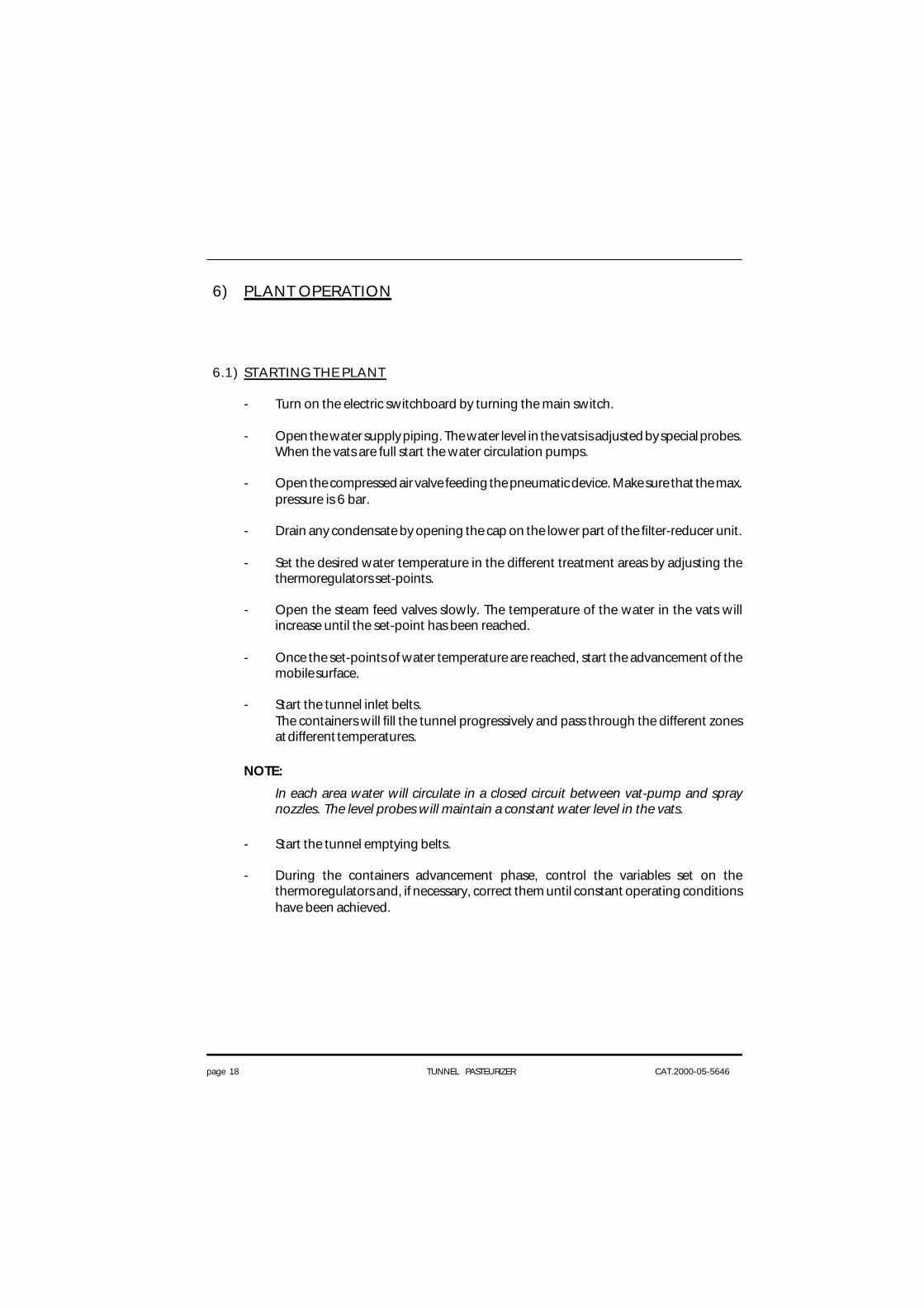
6) PLANT OPERATION
6.1) STARTING THE PLANT
- Turn on the electric switchboard by turning the main switch.
- Open the water supply piping. The water level in the vats is adjusted by special probes.When the vats are full start the water circulation pumps.
- Open the compressed air valve feeding the pneumatic device. Make sure that the max.pressure is 6 bar.
- Drain any condensate by opening the cap on the lower part of the filter-reducer unit.
- Set the desired water temperature in the different treatment areas by adjusting thethermoregulators set-points.
- Open the steam feed valves slowly. The temperature of the water in the vats willincrease until the set-point has been reached.
- Once the set-points of water temperature are reached, start the advancement of themobile surface.
- Start the tunnel inlet belts.The containers will fill the tunnel progressively and pass through the different zonesat different temperatures.
NOTE:
In each area water will circulate in a closed circuit between vat-pump and spraynozzles. The level probes will maintain a constant water level in the vats.
- Start the tunnel emptying belts.
- During the containers advancement phase, control the variables set on thethermoregulators and, if necessary, correct them until constant operating conditionshave been achieved.

page 19 TUNNEL PASTEURIZER CAT.2000-05-5646
6.2) STANDARD OPERATION
- Control that the operating conditions are equivalent to set conditions every now andthen. A non-stop recorder (optional) records some of the pasteurizing parameters.
- If a travelling thermoregulator is available, control the actual pasteurization cycle in thecontainer every now and then.
- Control the filters on the suction side of circulations pumps and clean them periodically.
6.3) STOPPING THE PLANT
- Wait until all the containers have come out of the tunnel.
- Close the steam, water and air supply valves.
- Stop the circulation pumps.
- Stop the tunnel inlet and outlet belts and the transport surface inside the tunnel itself.
- Turn off the appliance by turning off the main switch on the electric switchboard.
- Unload the water vats; clean and wash them.
- Clean the pump suction filters.
- If any nozzles are clogged, remove the nozzle holder, take off the nozzle caps using ascrewdriver and blow compressed air against the holes to clean them.
page 20 TUNNEL PASTEURIZER CAT.2000-05-5646
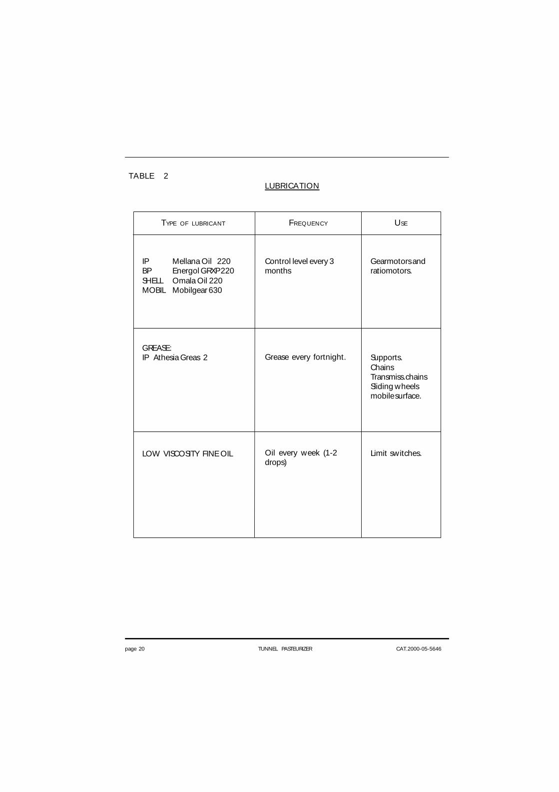
FREQUENCY
Control level every 3months
Grease every fortnight.
Oil every week (1-2drops)
USE
Gearmotors andratiomotors.
Supports.ChainsTransmiss.chainsSliding wheelsmobile surface.
Limit switches.
TABLE 2LUBRICATION
TYPE OF LUBRICANT
IP Mellana Oil 220BP Energol GRXP 220SHELL Omala Oil 220MOBIL Mobilgear 630
GREASE:IP Athesia Greas 2
LOW VISCOSITY FINE OIL
page 21 TUNNEL PASTEURIZER CAT.2000-05-5646
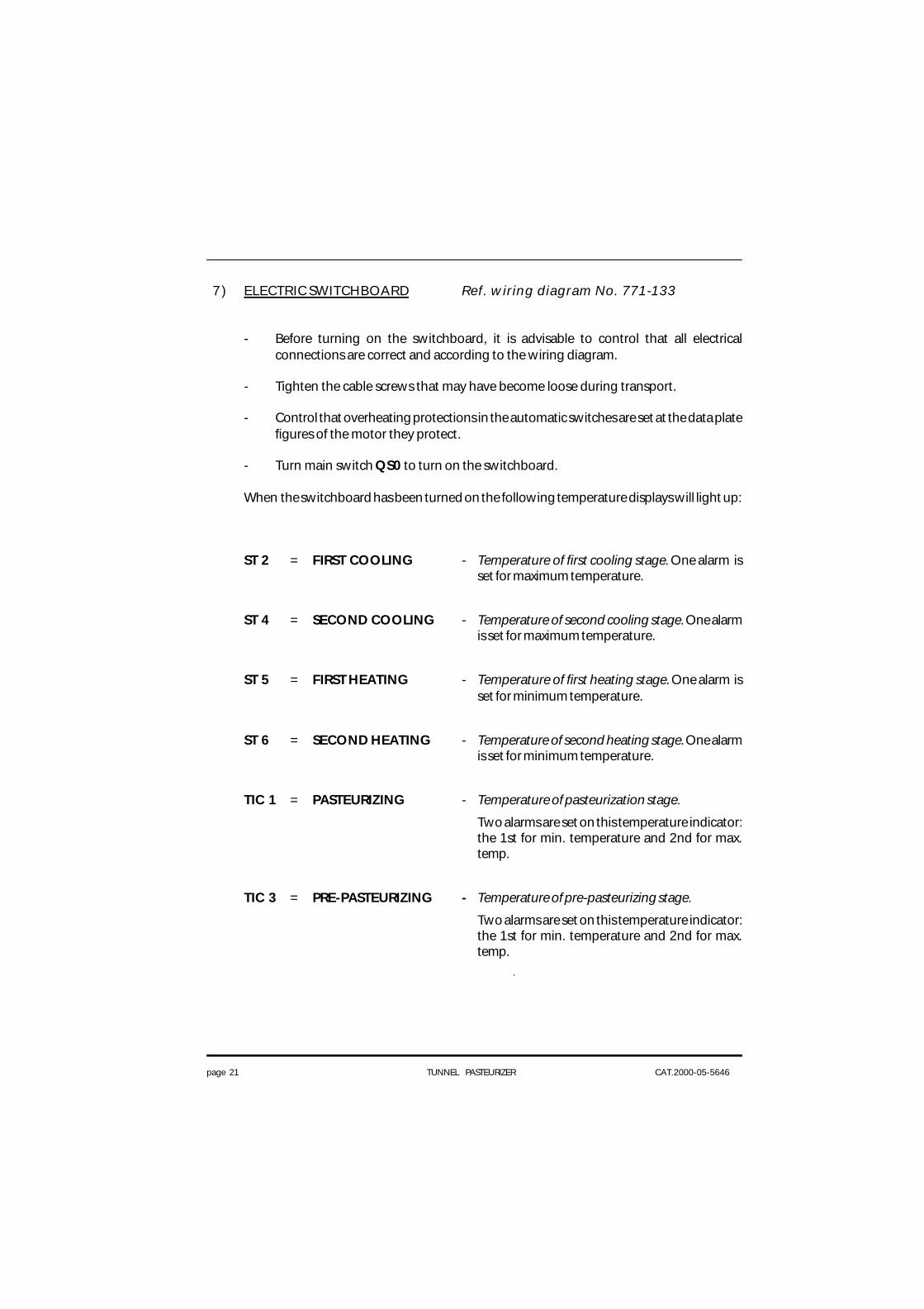
7) ELECTRIC SWITCHBOARD Ref. wiring diagram No. 771-133
- Before turning on the switchboard, it is advisable to control that all electricalconnections are correct and according to the wiring diagram.
- Tighten the cable screws that may have become loose during transport.
- Control that overheating protections in the automatic switches are set at the data platefigures of the motor they protect.
- Turn main switch QS0 to turn on the switchboard.
When the switchboard has been turned on the following temperature displays will light up:
ST 2 = FIRST COOLING - Temperature of first cooling stage. One alarm isset for maximum temperature.
ST 4 = SECOND COOLING - Temperature of second cooling stage. One alarmis set for maximum temperature.
ST 5 = FIRST HEATING - Temperature of first heating stage. One alarm isset for minimum temperature.
ST 6 = SECOND HEATING - Temperature of second heating stage. One alarmis set for minimum temperature.
TIC 1 = PASTEURIZING - Temperature of pasteurization stage.
Two alarms are set on this temperature indicator:the 1st for min. temperature and 2nd for max.temp.
TIC 3 = PRE-PASTEURIZING - Temperature of pre-pasteurizing stage.
Two alarms are set on this temperature indicator:the 1st for min. temperature and 2nd for max.temp.
page 22 TUNNEL PASTEURIZER CAT.2000-05-5646
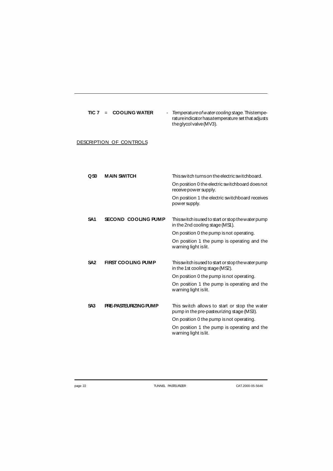
TIC 7 = COOLING WATER - Temperature of water cooling stage. This tempe-rature indicator has a temperature set that adjuststhe glycol valve (MV3).
DESCRIPTION OF CONTROLS
QS0 MAIN SWITCH This switch turns on the electric switchboard.
On position 0 the electric switchboard does notreceive power supply.
On position 1 the electric switchboard receivespower supply.
SA1 SECOND COOLING PUMP This switch is used to start or stop the water pumpin the 2nd cooling stage (MS1).
On position 0 the pump is not operating.
On position 1 the pump is operating and thewarning light is lit.
SA2 FIRST COOLING PUMP This switch is used to start or stop the water pumpin the 1st cooling stage (MS2).
On position 0 the pump is not operating.
On position 1 the pump is operating and thewarning light is lit.
SA3 PRE-PASTEURIZING PUMP This switch allows to start or stop the waterpump in the pre-pasteurizing stage (MS3).
On position 0 the pump is not operating.
On position 1 the pump is operating and thewarning light is lit.

page 23 TUNNEL PASTEURIZER CAT.2000-05-5646
SA4 PASTEURIZING PUMP This switch is used to start or stop the waterpump in the pasteurizing stage (MS4).
On position 0 the pump is not operating.
On position 1 the pump is operating and thewarning light is lit.
SA5 SECOND HEATING PUMP This switch allows to start or stop the waterpump in the heating stage (MS5).
On position 0 the pump is not operating.
On position 1 the pump is operating and thewarning light is lit.
SA6 FIRST HEATING PUMP This switch allows to start or stop the water pumpin the heating stage (MS6).
On position 0 the pump is not operating.
On position 1 the pump is operating and thewarning light is lit.
SA7 INLET BELT This switch is used to start or stop the motor(MS7) of the inlet belt.
On position 0 the belt is not operating.
On position 1 the belt is operating and thewarning light is lit.
SA8 TUNNEL BELT Unstable selector for conveyor belt control (MS8).
When conveyor belt is running the warning lightis lit.
SA9 P9 PUMP This switch is used to start or stop the pump(MS9).
On position 0 the pump is not operating.
On position 1 the pump is operating and thewarning light is lit.

page 24 TUNNEL PASTEURIZER CAT.2000-05-5646
SA10 TUNNEL BELT SELECTION Key selector for the AUTOMATIC or MANUALcontrol of conveyor belt.
In position 0 the belt is not running.
In position MAN the belt starts running by meansof SA8.
In position AUT the belt starts running by meansof SA8 according to temperature levels.
SA11 PASTEURIZING TEMPERATURE It selects the working temperature during cycle,allowing for changeover to the lower set in caseof prolonged interruptions of machine operation.
In position 1 (set 1) the selected temperature islow (pause temperature).
In position 0 (automatic) the working temperatu-re is normally selected (set 2).
In case of a prolonged interruption of machineoperation (belt stop due to clogging at outlet, forexample) exceeding the time set on timer KT1, themachine automatically changes over to the lowtemperature (set 1).
When the cause for the interruption is eliminated,the machine restarts at working temperature (set2), and cycle is then restarted.
SB0 EMERGENCY STOP This mushroom push button is pressed to cutpower supply to the entire control circuit, thereforeall the pumps and motors are stopped andwarning lights turn off. The temperature indicatorsstill receive power. Turn the emergency pushbutton (SB0) until it is released to supply poweragain and then press start push button (SH0).
SB2 SIREN STOP This push button, when pressed, stops the siren.
SH0 CONTROL STARTING Start luminous push button to energize theauxiliary control circuits.
When this push button is pressed it turns off.

page 25 TUNNEL PASTEURIZER CAT.2000-05-5646
DESCRIPTION OF SIGNALS
HL10 COLD WATER INLET TANK 1 The water level in container 1 is below theminimum level, with consequent opening of thesolenoid valve (YE1) to restore the set water level.Once the set level has been restored the warninglight (HL10) will turn off automatically.
HL11 COLD WATER INLET TANK 2 The water level in the container 2 is below theminimum level, with consequent opening of thesolenoid valve (YE2) to restore the set water level.Once the set level has been restored the warninglight (HL11) will turn off automatically.
HL12 COLD WATER INLET TANK 3 The water level in the container 3 is below theminimum level, with consequent opening of thesolenoid valve (YE3) to restore the set water level.Once the set level has been restored the warninglight (HL12) will turn off automatically.
HL13 COLD WATER INLET TANK 4 The water level in the container 4 is below theminimum level, with consequent opening of thesolenoid valve (YE4) to restore the set water level.Once the set level has been restored the warninglight (HL13) will turn off automatically.

page 26 TUNNEL PASTEURIZER CAT.2000-05-5646
HL14 MIN. TEMPERATURE ALARM Pasteurizing, pre-pasteurizing and 2nd coolingtemperatures below minimum level set onthermostat set 1 (TIC3, TIC4, TIC6).
HL15 MAX. TEMPERATURE ALARM Pasteurizing and pre-pasteurizing temperaturesabove maximum level set on thermostat set 2(TIC3, TIC4).
HL16 OVERLOAD OUTLET BELT Operation of outlet indicator (SQ9A, SQ9B).
HL17 MOTOR OVERLOAD One or more automatic cut-outs to protect themotors.
Remove the cause of overload.
Rearm the overload cut-out inside the electricpanel.
HS1 BLINKING LIGHT This warning light is activated by:
- minimum temperature of 1 st heating stage, 2 nd
heating stage , pre-pasteurizing and pasteurizing;
- maximum temperature of pre-pasteurizing,pasteurizing, 1st coooling and 2nd cooling;
- tunnel belt overload;
- motors overload.
HS2 SIREN This acoustic alarm is activated by:
- minimum temperature of 1 st heating stage, 2 nd
heating stage, pre-pasteurizing and pasteurizing;
- maximum temperature of pre-pasteurizing,pasteurizing, 1st coooling and 2nd cooling;
- tunnel belt overload;
- motors overload.

page 27 TUNNEL PASTEURIZER CAT.2000-05-5646
SH2 TUNNEL BELT OVERLOAD OVERLOAD alarm reset of the TUNNEL BELT.
(RESET) Remove the cause of overload to the sensor (SQ8).