Embed Size (px)
Citation preview

Part No. 52 800 987
Turbidity Transmitter
Trb 8300 D
Instruction Manual

IMPORTANT SAFETY INFORMATION • Follow all warnings, cautions, and instructions indicated on and supplied with this product.
• Install equipment as specified in this instruction manual. Follow appropriate local and national codes.
• Use only factory documented components for repair. Tampering or unauthorized substitution of parts and procedures can affect the performance and cause unsafe operation of your process.
• Protective covers must be in place unless qualified personnel are performing maintenance.
• If this equipment is used in a manner not specified by the manufacturer, the protection provided by it against hazards may be impaired.
WARNINGS:
• Installation of cable connections and servicing of this product require access to shock hazard voltage levels.
• Main power and relay contacts wired to separate power source must be disconnected before servicing.
• Main power must employ a switch or circuit breaker as the disconnecting device for the equipment.
• Electrical installation must be in accordance with the National Electrical Code and/or any other applicable national or local codes.
• Safety and performance require that this instrument be connected and properly grounded through a three-wire power source.
• RELAY CONTROL ACTION: the Trb 8300 D instrument relays will always de-energize on loss of power, equivalent to normally open state, regardless of relay state setting for powered operation. Configure any control system using these relays with fail-safe logic accordingly.
• PROCESS UPSETS: Because process and safety conditions may depend on consistent operation of this instrument, provide appropriate means to maintain operation during sensor cleaning, replacement or sensor or instrument calibration.
This instrument complies with the safety standards as outlined on our Ratings.
This manual includes safety information with the following designations and formats:
WARNING: POTENTIAL FOR PERSONAL INJURY
CAUTION: possible instrument damage or malfunction
NOTE: important operating information
Definition of Equipment Symbols
On the instrument indicates: Caution, risk of electric shock
On the instrument indicates: Caution (refer to accompanying documents)
~ On the instrument indicates: There is alternating current (AC) present.

TABLE OF CONTENTS
CHAPTER 1: INTRODUCTION......... 1 AT THE VERY BEGINNING ............................................1 INTENDED USE ..........................................................1 DESCRIPTION OF UNIT ................................................1 MEASUREMENT AND CONTROL SYSTEM......................2
CHAPTER 2: INSTALLING THE TRB 8300 D .............................................. 3
UNPACKING ...............................................................3 INSTRUMENT DESCRIPTION ........................................3
Front Panel..........................................................4 Rear Panel ..........................................................4
INSTRUMENT INSTALLATION ........................................5 Panel Mount ........................................................5 Wall Mount ..........................................................5
CONNECTIONS...........................................................6 Input Power .........................................................6 Sensor Connections............................................6 Other Connections ..............................................7
INITIAL START UP ......................................................8 Display Contrast Adjustment...............................8
CHAPTER 3: GETTING STARTED .. 9 OPERATING MODES ................................................... 9
Measure Mode ....................................................9 Menu Mode .........................................................9
USING THE DISPLAY AND KEYPAD .............................10 Display ..............................................................10 Keypad ..............................................................10 Data Entry .........................................................11
CHAPTER 4: USING MENUS......... 12 INTRODUCTION ........................................................12 MAIN MENU.............................................................12
Access...............................................................12 Exit ....................................................................12
PARAMETER SET MENU ...........................................13 Parameter Set ...................................................13 Units ..................................................................13 Name.................................................................13 Filter ..................................................................13
FACTORY DATA AND CALIRATION MENU....................13 MILLIAMP (MA) OUTPUTS MENU ...............................13
mA Output # ......................................................14 Scaling Type .....................................................14 Low Value (signal level) ...................................14 0/4 mA (scaling limit)........................................14 Mid (Bi-linear scaling only)...............................14 20 mA (scaling limit).........................................14 Num of Decades (logarithmic scaling only) .....14 On failure 22 mA ...............................................14 Current Out .......................................................14
SET HOLD MODE .....................................................15 HOLD state:.......................................................15
RELAYS MENU .........................................................15 Select Relay ......................................................15
LIMIT 1 AND 2...........................................................16 Signal.................................................................16 Value .................................................................16 Delay .................................................................16 Hysteresis..........................................................16 Set Point ............................................................16 State ..................................................................16
ALARM.....................................................................16 Delay .................................................................16 State ..................................................................16
WASH......................................................................16 Interval...............................................................16 Wash time..........................................................16 State ..................................................................17
SAVE/RECALL MENU...............................................17 Select.................................................................17 P-Set..................................................................17
RESET MENU .........................................................17 System...............................................................17 P-Set..................................................................17 Cal .....................................................................17
DIAGNOSTICS MENU ...............................................18 Transmitter ........................................................18 Sensor ...............................................................18 Self Tests...........................................................18
OTHER MENUS .........................................................19 Language MENU...............................................19 Security MENU..................................................19 Set Date/Time....................................................19 Set Unit Name ...................................................19 Lost Passwords .................................................20 RS232 set-up.....................................................20 Print Configuration.............................................20 Software Revs ...................................................20 Service Only ......................................................20
CHAPTER 5: FACTORY DATA AND CALIBRATIONS ............................. 21
INTRODUCTION.........................................................21 CALIBRATION TYPES ................................................21
Factory Calibration (Factory Data) ....................21 Process Calibration/Zero Point Adjustment ......21
CALIBRATION MENU .................................................22 CHOOSE ...........................................................22 NEW PROCESS CALIBRATION ......................22 SHOW PROCESS CALIBRATION....................22 RESET PROCESS CALIBRATION...................22
CHAPTER 6: MAINTENANCE & TROUBLESHOOTING .................... 23

MAINTENANCE .........................................................23 Front Panel Cleaning ........................................23
TROUBLESHOOTING CHECKLIST ...............................23 ERROR MESSAGES ..................................................24
CHAPTER 7: UPGRADE ................ 25 UPGRADES..............................................................25
Main program Software Upgrade......................25 Procedure..........................................................25
CHAPTER 8: ACCESSORIES AND SPARE PARTS............................... 27
ACCESSORIES .........................................................27 SPARE/REPLACEMENT PARTS ..................................27
APPENDIX A: MENU TREES......... 28 MAIN MENUE ...........................................................28 PARAMETER SET MENU ...........................................29 CALIBRATION MENUS ...............................................30 MA OUTPUTS MENUS ................................................31 RELAYS MENUS .......................................................32 SAVE/RECALL MENUS...............................................33 RESET MENUS .........................................................34 DIAGNOSTICS MENUS...............................................35 OTHER MENUS.........................................................36
APPENDIX B: SET-UP PARAMETER RECORD......................................... 37
MEASUREMENT PARAMETERS RECORD 1/2 ...............37 MEASUREMENT PARAMETERS RECORD 2/2 ...............38
APPENDIX C: SPECIFICATIONS .. 39
APPENDIX D: RATINGS ................ 42 Declaration of Conformity .................................42 UL Recognition .................................................42
APPENDIX E: WARRANTY............ 43

Chapter 1 Introduction 1
CHAPTER 1: INTRODUCTION
AT THE VERY BEGINNING
We thank you for having purchased the METTLER TOLEDO Turbidity Transmitter Trb 8300 D.
This manual covers routine operation, service and communication of the Trb 8300 D.
The instruction manual must always be stored close at hand, in a place accessible to all persons working with the turbidity Transmitter Trb 8300 D.
If you have questions, which are not or insufficiently answered in this instruction manual, please contact your METTLER TOLEDO supplier. They will be glad to assist you.
INTENDED USE
The METTLER TOLEDO Turbidity Transmitter Trb 8300 D combined with the sensor InPro 8600/D are intended solely for measurements in liquids, as described in this instruction manual. Any other use, or use not mentioned here, that is incompatible with the technical specifications is deemed inappropriate. The operator is solely responsible for any damage arising from such use.
Other prerequisites for appropriate use include:
- Observing the instructions, notes and requirements set out in this instruction manual.
- Observing all local safety regulations concerning safety at work.
- Observing all information and warnings in the documentation dealing with products used together with the transmitter (sensors, housings etc.)
- Observing the prescribed environmental and operational conditions
DESCRIPTION OF UNIT
The Trb 8300 D is a transmitter for high accuracy measurement and control. It accepts input from METTLER TOLEDO InPro 8600/D sensor only.
The measuring system can be used for applications in the beverage industry and brewery processes.
A METTLER TOLEDO turbidity system consists of:
- Trb 8300 D transmitter (100…240 VAC or 20…32 VDC power supply)
- InPro 8600/D sensor
The present manual describes the operation of both, 100… 240 VAC and 20…32 VDC power supply version. Furthermore it contains information on the sensor:
- InPro 8600 combined forward/90° scattered light sensors
For detailed information on installation, operation and maintenance of InPro8600 sensor please refer to the sensors manual which is delivered which every sensor. You can also download the manuals on our Website (www.mt.com).
A system consisting of the Trb 8300 D transmitter and an optical InPro8600 sensor measures:
- turbidity from 0…400 FTU (NTU) or 0…100 EBC on a Formazin based scale
or
- concentration of suspended (undissolved) solids or oil in water from 0…1000 ppm or 0…1.0 g/l derived from measurements with suspended diatomaceous earth as reference substance

Chapter 1 Getting Started 2
The transmitter has many user-friendly and safety features which include:
- RS232 interface for data transfer of configurations and software updating
- Process Calibration procedure - three retrievable, independently configurable Parameter
Sets with remote access via digital inputs - full text menu guide in three languages - online help texts - menu password protection on two levels - four 0/4...20 mA outputs galvanically isolated from the
measurement circuitry according to NAMUR NE43 guideline
- 2 programmable limit setpoints, 1 alarm relay (SPDT type)
- HOLD input and Wash contact (SPDT type) Turbidity measurements take advantage of the interaction of light and undissolved particles or emulsified droplets (oil in water).
The light source is placed in the sensor. The receiving silicon photodiodes are placed in the sensor as well. The produced photocurrents are converted to turbidity values in the sensor and the resulting turbidity values are transferred to the transmitter via the RS485 cable. The photodiodes are placed in angles of 0°, 25° (forward scattered beam ) and 90° (sideward scattered beam) of the emitted light beam. The 0° detector measures the direct light, the 25° and 90° detectors measure the intensity of the scattered light.
METTLER TOLEDO InPro 8600 turbidity sensors take advantage of the so called ratio measurement. The signals of scattered and direct light detectors will be processed by the sensor, amplified, divided and shown as turbidity values on the display of the transmitter and mA outputs:
Turbidity = scattered light signal/direct light sig nal
With increasing turbidity the particles inside the process liquid decrease the intensity of the direct light and increase the intensity of the scattered light. Color of the liquid caused by dissolved substances decreases the intensity of direct and scattered light in the same ratio – as a result the turbidity reading is independent of color changes. Lamp ageing and possible optical window fouling within the sensor are compensated by this ratio also.
The forward scattered sensors are factory calibrated and available for Varivent process connections (see also InPro8600 Instruction Manual).
MEASUREMENT AND CONTROL SYSTEM
A typical measurement system consists of:
- Turbidity process transmitter Trb 8300 D
- A sensor InPro8600/D
- A final control element such as pump or valve
- Device for recording measured values

Chapter 2 Installing the Trb 8300 D 3
CHAPTER 2: INSTALLING THE Trb 8300 D
UNPACKING
Carefully unpack the Trb 8300 D, the carton should contain:
• Trb 8300 D instrument • mounting screws, 4 pcs.
• Trb 8300 D Instruction Manuals
(English, French and German versions)
• panel mounting gasket
• Connector blocks for TB2 to TB7
INSTRUMENT DESCRIPTION
Shown below are the Trb 8300 D enclosure dimensions:
front dimensions – [mm] inches
side dimensions – [mm] inches
ME
TT
LE
R T
OL
ED
O
Trb 8300 D

Chapter 2 Installing the Trb 8300 D 4
rear dimensions – [mm] inches
Front Panel Display : The backlit LCD display has four lines of 20 characters each.
Keypad: The keypad consists of 9 function keys and 11 alphanumeric entry keys. See Chapter 3: Getting Started for a detailed description of each key.
front panel
Rear Panel All electrical, relay, input, output, and communication connections are made via the rear panel of the Trb 8300 D. See CONNECTIONS later in this section.
Trb 8300 D
ME
TT
LE
R T
OL
ED
O

Chapter 2 Installing the Trb 8300 D 5
INSTRUMENT INSTALLATION
Panel Mount The Trb 8300 D is supplied with four mounting screws and a gasket to provide a seal at the panel cutout.
To mount the Trb 8300 D in an instrument panel:
1. Use the illustration below to mark panel cutouts.
panel cutout – [mm] inches
If multiple instruments are to be mounted in the same panel, allow enough space for the flanges to overlap the panel between instruments (dotted outline).
2. Make the panel cutout and drill the mounting screw holes; all cutouts should be clean and free of burrs.
3. Remove the backing paper and slide the adhesive gasket onto the rear of the instrument flange. Align it evenly and press into place. The two small pins near each screw hole are intended to control compression of the gasket for optimum sealing.
4. Slide the Trb 8300 D into the panel and secure with four 6-32 mounting screws (supplied) from the back.
Wall Mount For wall mounting the transmitter Trb 8300 D needs to be installed in an additional stainless steel IP66 (NEMA 4X) field housing (METTLER TOLEDO part number 52 800 867).

Chapter 2 Installing the Trb 8300 D 6
CONNECTIONS
All connections are made via the rear panel. InPro 8600 cable wires are marked with corresponding numbers found on TB7. Outputs on TB2 and TB3 include 4 analog outputs, RS232 plus 4 discrete inputs. Four relays are on TB5 and TB6.
rear panel terminal boards
WARNING: MAKE SURE POWER TO ALL WIRES IS TURNED OFF BEFORE PROCEEDING WITH THE INSTALLATION. HIGH VOLTAGE MAY BE PRESENT ON THE INPUT POWER WIRES AND RELAY WIRES.
For TB5 and TB6 relay terminals use 26 AWG (0.126 mm2) to 14 AWG (2.08 mm2). If more than one wire has to be connected to a terminal, wire size must be further limited.
Input Power The Trb 8300 D, part number 52 800 927 , has a universal power supply for operation in the range of 100-240 VAC, 47-63 Hz.
Terminal block TB1 provides the connections for the input line power. See above section for wire sizes. Turn the terminal screws fully counterclockwise, then insert the appropriate wire into its terminal and securely tighten adjacent screw.
CAUTION: a full 0.5 in. (13 mm) of bare conductor must be exposed for reliable power connection to these d eep terminals. This is much more than is required for o ther terminals. For AC power, make connections as follows:
Board Terminal Connection
Earth ground
TB1 N AC power, neutral
L AC power, hot
The Trb 8300 D, part number 52 800 928, has a universal power supply for operation in the range of 20…32 VDC.
Terminal block TB1 provides the connections for the input line power. See above section for wire sizes. Turn the terminal screws fully counterclockwise, then insert the appropriate wire into its terminal and securely tighten adjacent screw.
CAUTION: a full 0.5 in. (13 mm) of bare conductor must be exposed for reliable power connection to these d eep terminals. This is much more than is required for o ther terminals. For AC power, make connections as follows:
Board Terminal Connection
Earth ground
TB1 PS- DC power, minus
PS+ DC power, plus
WARNING: MISWIRING THE POWER MAY CAUSE A HAZARD, DAMAGE THE INSTRUMENT AND WILL VOID ALL WARRANTIES.
Sensor Connections The connection between InPro 8600 sensor and Trb 8300 D transmitter is performed with a RS 485 cable. It is available from METTLER TOLEDO in 3 lengths:
52 800 978 RS 485 cable 5m for InPro 8600
52 800 979 RS 485 cable 10m for InPro 8600
52 800 981 RS 485 cable 20m for InPro 8600
Board Terminal Connection
1 RS 485 + (green)
2 RS 485 - (yellow)
TB 7 3 Shield (green/yellow)
4 24 VDC + Sensor (brown)
5 24 VDC - Sensor (white)

Chapter 2 Installing the Trb 8300 D 7
Other Connections Each connection terminal and terminal block are labeled by number. The following tables identify each connection.
Board Terminal Connection
1 Do not use !
2 Return Parameter Set A, B and HOLD
3 Do not use !
4 Parameter Set B
TB2 5 Do not use !
6 HOLD
7 Parameter Set A
8 RS232 ground
9 RS232 receive
10 RS232 transmit
11 Do not use !
12 Return Parameter Set C
13 Parameter Set C
14 Do not use
TB3 15 Analog mA output 4 +
16 Analog mA output 3 +
17 Analog mA output -
18 Analog mA output -
19 Analog mA output 2 +
20 Analog mA output 1 +
TB5 1 Alarm, normally closed
2 Alarm common
3 Alarm, normally open
4 Wash, normally closed
5 Wash, common
6 Wash, normally open
TB6 7 Limit 1, normally closed
8 Limit 1, common
9 Limit 1, normally open
10 Limit 2, normally closed
11 Limit 2, common
12 Limit 2, normally open
Discrete Inputs
Discrete (digital) inputs (TB2-4,6,7 and TB3-13) allow external dry isolated contacts to pull their +5V logic level to common (TB2-2 and TB3-12) to provide discrete control action within the Trb 8300 D. This control may be used to hold the current (mA) outputs (see Chapter 4 Set HOLD Mode) and to select one of three Parameter Sets .
CAUTION: Route wiring to discrete inputs away from power or switching circuits and provide shielding t o an earth ground at the far end of the cable.
Current (mA) Outputs
Connections for current outputs are on TB3. Note that connections use common terminal (18) for current outputs 1 and 2 and common terminal (17) for current outputs 3 and 4. Current outputs are self-powered and have a maximum load capacity of 500 ohms.
CAUTION: Do not connect current outputs to circuit s supplying power. They are already powered.

Chapter 2 Installing the Trb 8300 D 8
INITIAL START UP
When power is first supplied to the Trb 8300 D, a message similar to the following will be displayed:
******************** METTLER TOLEDO Trb 8300 D vX.XX ********************
The second line indicates the instrument main software version.
After a first time start-up of a factory-new transmitter, the instrument goes into a language menu after powering-up. Select your menu language - English, German or French
If a sensor is connected, the transmitter will auto-recognize the sensor and load sensor specific data including the factory calibration data.
If no sensor is connected, the transmitter will show “No sensor found” on the display. The menus are still accessible.
See "USING THE DISPLAY AND KEYPAD" in CHAPTER 3: GETTING STARTED to make yourself familiar with the basic operations. For detailed calibration instructions, see Chapter 5, Factory Data and Calibration.
After initialization and diagnostic checks, the display will go to measurement mode.
Display Contrast Adjustment Depending on ambient lighting and temperature conditions, some adjustment of the LCD display contrast may be needed. Allow the instrument to warm up to operating conditions before making an adjustment. Loosen the two captive front panel screws and lift the front panel off. Using a fine screwdriver, adjust the small potentiometer on the left side below the display to obtain the desired contrast. Replace the front panel.

Chapter 3 Getting Started 9
CHAPTER 3: GETTING STARTED
Please read this chapter for an overview of the Trb 8300 D. It will help you understand the operating system and how to use the display and keypad for data entry.
The following chapters provide detailed information on using the Trb 8300 D:
Chapter 4: Using Menus – understanding the menu system, options, and configuration for your applications.
Chapter 5: Calibrations – understanding the calibration procedure.
For help diagnosing and resolving measurement problems, see Chapter 6: Troubleshooting .
OPERATING MODES
The Trb 8300 D has two operating modes:
• Measure – used to present measurement data; the instrument will usually be in this mode.
• Menu – used to set up the system for your specific applications and access all other operational features.
Measure Mode Three Parameter Sets can be configured in the Trb 8300 D. In display mode, the measurement of the active Parameter Set (P-Set) is displayed.
P-Sets
Parameter Sets (P-Sets) are termed A through C. In each P-Set the instrument can be configured according to the requirements of a specific application. Each configuration includes calibration, ranging of current outputs, definition of setpoints, and wash intervals and lengths. If the application changes the corresponding P-Set can be retrieved, modified and saved again if necessary. This feature is extremely helpful if the sensor is installed in a pipe in which different process liquids or process requirements have to be monitored.
Measurement Units
The Trb 8300 D accommodates the following measurement units:
• FTU – Formazin Turbidity Units • NTU – Nephelometric Turbidity Units
• EBC – European Brewery Convention • ASBC – American Society of Brewing Chemist • ppm – Parts per million
• g/l – grams per liter with 1 FTU = 1 NTU = 0.25 EBC = 17.5 ASBC = 2.5 ppm = 0.0025 g/l
The turbidity values FTU, NTU EBC, or ASBC are used if the turbidity of the process liquid is measured on a Formazin based scale.
ppm or g/l is used when the undissolved solid content has been determined by an alternative measurement, i.e. dry mass measurements of grab samples or offline measurements.
The factory adjusted factor of 2.5 (1 FTU = 2.5 ppm) results from a representative measurement with diatomaceous earth as turbidity reference substance.
Menu Mode Menu mode allows you to set up the Trb 8300 D specifically for your applications.
The Main Menu consists of many sub-menus in a loop, which can be scrolled through for easy access. These sub-menus allow you to:
• Define Parameter Sets • Calibrate the system
• Define current (mA) outputs • Define limit setpoints and wash intervals • Save/Recall Parameter Sets
• Reset different configurations • Perform diagnostic functions • Configure less commonly used unit functions
Each menu may consist of one or more screens, or pages, where you define the desired settings.

Chapter 3 Getting Started 10
The remainder of this chapter describes how to use the keypad and display to define settings and enter information in menu mode.
The next chapter, Chapter 4: Using Menus , details the content of each menu.
USING THE DISPLAY AND KEYPAD
The Trb 8300 D operating system is very straightforward, but understanding a few rules will make it easier to navigate.
Display The four-line display provides read-out of measurement data as well as all menu screens and data entry fields.
Most display information and prompts are self-explanatory, for further assistance press «Help» and page down to read the message. Press «Help» again to return to the original screen.
If an up or down arrow is shown on the right side of the display, then more screens of information are available.
A flashing value in the display mode indicates a setpoint for that measurement has been exceeded. A high alarm condition is indicated by “>” after the value. A low alarm condition is indicated by “<”.
A flashing “H” on the display indicates that the transmitter is in HOLD mode. A flashing “ProCal ” in the measurement display indicates that a Process Calibration has been started and is waiting to be finished (see Chapter 5: Calibrations). Example display:
Measurement P-Set A (Process1) 25:0.2 EBC ProCal 90: 0.5 EBC H
A letter before the measurement unit indicates a multiplier. The units multipliers are:
• m (milli) = multiply value by 0.001 (10-3)
• _ (units) = multiply value by 1
Keypad The keypad consists of 9 function keys and 11 alphanumeric entry keys.
«Menu (exit)»
Press «Menu (exit)» to access the menu mode. Press «Menu (exit)» again to exit the menu mode.
«Page Up» / «Page Down»
Press «Page Down» to move to the next screen of infor-mation (if any). Press «Page Up» to move to the previous screen of information (if any). Additional screens are indicated by an up or down arrow on the right side of display.
When finished with a data entry screen, press «Page Down» to go to the next one.
«Help»
Press «Help» to view more information or instructions regarding the current screen or data entry field.
Press «Page Up» or «Page Down» as necessary to view the entire message. Press «Help» again to return to the original screen.
«Enter»
Press «Enter» to select a menu option, to select an option from a list, to complete an alphanumeric entry, or move to the next data entry field.
Arrow keys
The four arrow keys function as follows:
• «Up» – press to view the next item in a list of options. • «Down» – press to view the previous item in a list of
options. • «Left» – press to move the cursor left in a line of text or
numbers (may also move cursor to the previous field). • «Right» – press to move the cursor right in a line of text
or numbers (may also move cursor to the next field).
Alphanumeric keys
The alphanumeric keys are multi-functional. For example, the «1» key can be used to type the letters "A, B, C" in either upper or lower case, as well as the numeral "1."
Repetitive presses of the same key produce the different entries. Using the «1» key as an example:
• first press = A • second press = B • third press = C
• fourth press = a • fifth press = b • sixth press = c
• seventh press = 1 then the sequence repeats.

Chapter 3 Getting Started 11
Notes:
The «0» key will yield the following characters: / = : ( ) 0
The «-» key will yield the following characters:. - + ^ _ ! $
If another letter from the same key is desired, the «Right» arrow key must be used to move the cursor to the next position in the data entry field.
When a different key is pressed, the cursor automatically moves to the next position.
If a lower case letter is selected, the next key pressed will begin the sequence with the lower case.
The «Up» and «Down» arrow keys can be used to scroll through the entire alphabet.
If the Trb 8300 D is expecting a numeric entry, the first press will yield the number on the key.
Data Entry In menu mode, each line of the display presents an option followed by a data entry field.
If a colon “:” follows the field name, use the «Up» and «Down» arrow keys to scroll through a list of options.
If an equal sign “=” follows the field name, use the alphanumeric keys to enter the required information. (See Alphanumeric Keys above.) When the desired option is selected or the alphanumeric entry complete, press «Enter» to move the cursor to the next field. (When the last field on a screen has been completed, pressing «Enter» will return the cursor to the top of the screen.)
If the menu consists of more than one screen of fields, press «Page Down» to continue.

Chapter 4 Using Menus 12
CHAPTER 4: USING MENUS
INTRODUCTION
After installation and connecting a sensor use the menu system to set up the Trb 8300 D for your measurements.
First, set up the Parameter Set for each application. Then go through the rest of the menus for calibration and to set any outputs, set points, relays and other functions as necessary. Menu selections are automatically saved as you make them, although on exiting menus you can restore previous settings.
If desired, photocopy the Measurement Parameters Record form provided in Appendix B to record the menu options selected.
After all menu options have been set, return to display mode to view measurement readings.
MAIN MENU
The Main Menu is used for all instrument functions except the actual display of measurements. The following sub-menus are available from the Main Menu:
• Parameter Set – define measurement unit and name of P-Set.
• Calibration – select and perform the calibration routine for your measurement. This is only necessary if you do not want to work with the factory calibration.
• mA Outputs – scale current outputs, and define HOLD mode.
• Relays – define limit set points, type (high, low), alarm relay action, and wash cycles.
• Save/Recall – activate a P-Set by recalling it or save your current settings to another P-Set.
• Reset – return settings to default values.
• Diagnostic – access a series of diagnostic testing routines.
• Other Menus – access to less commonly used menus. Language – select your dialog language (English, German or French) Set Date/Time – enter date and time. Set Unit Name – enter a descriptive name for this instrument. Lost Passwords – retrieve lost passwords.
RS232 Set-up – format the Data output communication parameters
Print Config – print current set-up information via the RS-232 port. Software Revs – display revision of installed software.
Service Only – for use by METTLER TOLEDO Service personnel only.
Security – enable password protection.
Access To access the Main Menu, press «Menu (exit)» . If security is active, a prompt for a password will appear.
Press the «Up» or «Down» key to step through the main Menu. Press «Enter» to select a menu.
NOTE: Access to menu functions can be password protected for security. If you are locked out, you can still review settings but not change them. Press any alphanumeric key as the (wrong) password and press «Enter» to review menu settings.
Exit After completing all data entry for one menu option:
• Press «Page Up» until you return to the Main Menu to select another menu option; or
• Press «Menu (exit)» twice to save settings, exit the menu system and return to display mode.
• If no keys are pressed for 5 minutes, the Measure mode will resume automatically and settings will be saved.
To exit menus and discard any changes made:
• Press «Menu (exit)» once and then press «1» to exit the menu system, revert to the prior menu settings, and return to the display mode.

Chapter 4 Using Menus 13
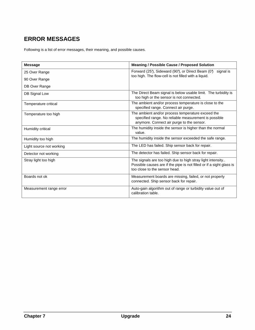
PARAMETER SET MENU
Parameter Set Three different Parameter Sets may be defined in the system memory. Each Parameter Set definition will be identified by a letter (A through C) which will become a line on the display in the normal measuring mode and other menus as P-Set.
Units The Trb 8300 D accommodates the following measurement units:
• FTU – Formazin Turbidity Units • NTU – Nephelometric Turbidity Units • EBC – European Brewery Convention
• ASBC – American Society of Brewing Chemist • ppm – Parts per million • g/l – grams per liter
with 1 FTU = 1 NTU = 0.25 EBC = 17.5 ASCB = 2.5 ppm = 0.0025 g/l The turbidity values FTU, NTU EBC, or ASBC are used if the turbidity of the process liquid is measured on a Formazin based scale.
ppm or g/l is used when the undissolved solid content has been determined by an alternative measurement, i.e. dry mass measurements of grab samples or offline measurements.
The factory adjusted factor of 2.5 (1 FTU = 2.5 ppm) results from a representative measurement with diatomaceous earth as turbidity reference substance.
Name Each Parameter Set can be given a custom name for easier identification (up to eight alphanumeric or symbol characters). If a name is not entered, the Parameter Set will default to "none". The name may be overwritten as desired.
Note: See Chapter 3: Getting Started for instructions on using the alphanumeric keys
To exit the Parameter Set menu see Chapter 4: Using menus.
Press «Menu (exit)» to go to the Measure Mode before accessing the Calibration Menu.
Filter Filtering stabilizes measurements readings in applications with noisy signals. The following options are available:
“none ”, Low Pass Low ”, Low Pass Medium ”, or Low Pass High ” Filter.
FACTORY DATA AND CALIBRATION MENU
METTLER TOLEDO InPro8600 sensors are factory calibrated with Formazin turbidity solutions. On initial start-up of the measuring system the corresponding sensor calibration data are automatically transferred from the sensor to the transmitter.
For detailed calibration instructions, see Chapter 5. Correct start-up and calibration as well as the understanding of the calibration routine are absolutely necessary for accurate measurements.
MILLIAMP (mA) OUTPUTS MENU
The 0/4-20 mA Outputs Menu is used to assign current outputs to measurements and define any necessary options. Furthermore HOLD Mode and Signal Filters for all four outputs are defined.
NOTE: Outputs are programmed to fulfill requirement s of NAMUR NE43. This means that in an over-range condition, the outputs will be set to 20.5 mA. In a n under-range condition the outputs will be set to 0 mA or 3.8 mA (if low value is set to 4 mA).
Use the «Up» and «Down» arrow keys in the mA Output menu to select mA-Output # ( = number), then press «Enter» to continue with setting up one of the current outputs.
Four current outputs are provided. Each output can be programmed to operate as a normal (i.e., linear), bi-linear, auto-range, or logarithmic output and to send a 22 mA signal if a system failure is detected.
See Chapter 2: Installing the Trb 8300 D for connection information.

Chapter 4 Using Menus 14
mA Output # Select Signal
Use the «Up» and «Down» arrow keys to select the desired signal. Select 25 (forward) to assign the turbidity value of the 25° forward scattered light sensor to one of th e mA outputs. Select 90 (sideward) to assign the turbidity value of the 90° scattered light sensor to one of the mA out puts. Press «Page Down» to continue.
mA output #
Use the «Up» and «Down» arrow keys to select the desired output (1 through 4), then press «Enter» to continue with set-up for that output. Complete all set-up parameters for one output before starting another.
To set up the next output, press «Page Up» until you return to the initial current output screen and then select another current output number.
Scaling Type The following types of output scaling are available: normal, bi-linear, auto-range, and logarithmic.
Normal scaling provides a linear 4 mA (or 0 mA) to 20 mA output. Low and high measurement values can be entered to correspond to those outputs.
Bi-linear scaling provides two scaling ranges for a single linear strip chart: usually a wide measurement range at the high end of the scale, and a narrower range with high resolution at the low end.
In addition to entering low and high values, a mid-range scaling value must be defined. For example, a user may want to monitor a particle breakthrough into the liquid phase during a liquid/solids separation process. Measurements are normally in the range of 5-20 FTU but during a particle breakthrough, a range of up to 200 FTU is desirable. Settings for the low, mid and high values might be 5, 20 and 201 FTU, to give convenient plotting on a 10-division strip chart.
Auto-Range scaling provides two ranges of output. It is designed to work with a PLC or two points of a multipoint strip chart recorder to meet the same needs as bi-linear scaling above.
Two separate settings are used, one for the high limit of the high range and one for the high limit of the low range, for the single 0/4-20 mA signal. The low value is always zero.
For the particle breakthrough example above, with rising concentration, the 0/4-20 mA signal would go from 0-100% for 0-20 FTU, decrease to 10% , then go 10-100% for 20-201 FTU. Thus both 0-20 and 0-200 FTU ranges may be recorded on the same chart using a single signal.
Logarithmic scaling provides an output for use with logarithmic chart paper. A high value and the number of decades must be entered. The low value is defined by the
other two settings. For example, a high value of 1000 ppm with 3 decades would give a range of 1–10–100–1000 ppm.
Low Value (signal level) Select 4 mA or 0 mA as the low value of the output signal.
0/4 mA (scaling limit) Enter the measurement value that will correspond to 4 mA (or 0 mA).
Whenever the measurement is equal to this number, the output signal will be set to its minimum value. Whenever the measurement is less to this number it will be set to 0 mA or 3.8 mA when 4 mA has been selected (NAMUR NE43).
If the output scaling type is auto-range, the low value is always zero.
Note: Output signals can be "inverted" by setting the minimum value higher than the maximum.
Mid (Bi-linear scaling only) Enter the measurement value that will correspond to the middle of the range (10 or 12 mA).
20 mA (scaling limit)
Enter the measurement value that will correspond to 20 mA.
Whenever the measurement is equal to this number, the output signal will be set to its maximum value. Whenever the measurement is greater than this number it will be set to 20.5 mA (NAMUR NE43).
Num of Decades (logarithmic scaling only)
Select the number of decades for the scale, from 1 to 6 (e.g., 1 to 100 is two decades).
On failure 22 mA If the system or measurement fails, the system can failsafe to either 22 mA or not. In the case that the failsafe is set to off, the output will go to 20.5 mA. . This state is displayed as asterisks “*****” on the front panel display.
Current Out Displays the actual current (mA) being outputted.

Chapter 4 Using Menus 15
SET HOLD MODE
The Set HOLD Mode menu is used to configure the HOLD state of the transmitter. During configuration and wash intervals, the transmitter can remain in the HOLD state for reasons of safety. The output currents are frozen (at last value or at a preset fixed value, depending on the configuration), limit and alarm relays are set to their non-activated status. If a meter is on hold, this is indicated by a flashing “H“ on the display.
HOLD state: No HOLD: The transmitter is never set to a HOLD state. It is always in a live state.
CAUTION: this setting can lead to unintentional switching of alarm/ and limit relays as well as to unexpected mA output readings when configuring the transmitter.
Fix: The current outputs (1-4) are frozen to a defined value when the transmitter goes into the HOLD state.
Fix Value: Enter the mA output value for the HOLD state.
Last: The current outputs are frozen to the last value as soon as the transmitter goes into the HOLD state.
NOTE: The transmitter is also set into the HOLD state if the corresponding discrete input is activated (see chapter 2, Discrete Inputs). If “No HOLD” has been selected in the software menu, mA-outputs are only frozen at their last value when the digital input activates the HOLD.
RELAYS MENU
The Relays Menu is used to define measurement limits, alarm conditions, a wash interval and length. All relays are SPDT (Single Pole Double Throw) types.
CAUTION: The default software settings for the rela ys, and the descriptions of the relay operations below, assume that the relays are wired in the following m anner (see Chapter 2):
Limit 1 to TB6 pins 8 and 9 (normally open)
Limit 2 to TB6 pins 11 and 12 (normally open)
Alarm to TB5 pins 1 and 2 (normally closed)
Wash to TB5 pins 5 and 6 (normally open)
When the measurement value is higher than a high limit value or lower than a low limit value, an alarm condition exists. Limit alarm conditions are indicated by a flashing measurement reading when in the display mode. Also, the corresponding relay is closed when a limit value is exceeded.
The Alarm relay is opened in case of a system or power failure.
NOTE: Setpoints are defined for a specific Parameter Set. The active Parameter Set is displayed in the Relay menus .
Select Relay Use the «Up» and «Down» arrow key to select a Relay (Limit 1 or 2, Alarm or Wash), then press «Page Down» to continue with the set-up for that relay. Complete all set-up parameters for one relay before starting another.
To set-up the next relay, press «Page Up» until you return to the initial relay screen and then select another relay.

Chapter 4 Using Menus 16
LIMIT 1 AND 2
Signal Select 25 (forward) to define a limit value for the 25° forward scattered light sensor. Select 90 (sideward) to assign a limit value for the 90° scattered light sensor. Press «Enter» to continue.
Value Enter the desired setpoint value in the measuring units displayed.
Delay A time delay requires the limit value to be exceeded continuously for a specified length of time before activating the relay. Enter the delay time in seconds.
If the condition disappears before the delay period is over, the relay will not be activated.
Hysteresis A hysteresis value requires the measurement to return within the limit value by a specified percentage before the relay is deactivated.
For a high setpoint, the measurement must decrease more than the indicated percentage below the limit value before the relay is deactivated. With a low setpoint, the measurement must rise at least this percentage above the limit value before the relay is deactivated. For example, a high setpoint is set at 100 and the measurement is currently above this value so that the setpoint is exceeded and the relay is activated. If the hysteresis value is 10%, then the measurement must fall below 90 before the relay is deactivated.
Enter a percentage value. No greater than 50%.
Set Point Select high or low. Select Off to disable the Set Point and to avoid relay triggering.
State The State setting allows the operator to decide whether the relay will be physically activated or not during normal operation. If the N.O. state is selected then the relay contacts will be open when the limit is not exceeded or when the power is off (relay deactivated). The relay contacts will close when the limit is exceeded (relay activated). This is the default setting. If the N.C. state is selected then the relay contacts will be open when the limit is exceeded and when power is off (relay deactivated). The relay contacts will be closed when the measurement is within the limits (relay activated). This assumes that the contacts are wired as described at the start of the relay section.
ALARM
The alarm relay is activated in case of system or power failure.
Delay A time delay requires the alarm state to exist continuously for a specified length of time before activating the relay. Enter the delay time in seconds.
If the alarm condition disappears before the delay period is over, the relay will not be activated.
State The State for the Alarm relay can not be changed. The relay will always be activated and the contact is open when there is no alarm. The relay contact will close when there is an alarm or when the power fails or is shut off.
Use alarm if mA outputs are under-/over-range If one of the defined measuring ranges (see Chapter 4, mA Output #) is exceeded, the Alarm relay can be activated. Select yes or no.
WASH
Interval Enter the time between two wash cycles in hours. The smallest possible value is 0.010 hr (36 seconds). The greatest possible value is 999.9 hours. The Wash relay will be activated when the interval time has been counted down. Enter 0.000 hr for deactivating the wash function. Press «Enter» .
Depending on HOLD state settings, the instrument will go into the HOLD state when a wash cycle has been started (see chapter 3, HOLD state).
Wash time Enter the time which is needed for a washing cycle in seconds. The greatest possible value is 600 seconds. Press «Enter» . The wash relay will be activated for the length defined here plus a fixed post delay time of 20 seconds. After this time the instrument will leave the HOLD state - if activated.
Chapter 4 Using Menus 17
State The State setting allows the operator to decide whether the relay will be physically activated or not during normal operation. If the N.O. state is selected then the relay contacts will be open when the wash is off or when the power is off (relay deactivated). The relay contacts will close when wash starts (relay activated). This is the default setting. If the N.C. state is selected then the relay contacts will be open when the wash is on or when power is off (relay deactivated). The relay contacts will be closed when the wash is off (relay activated). This assumes that the contacts are wired as described at the start of the relay section.
SAVE/RECALL MENU
In the previous sections all settings for a certain application have been defined in one Parameter Set (P-Set A through C) and have been automatically saved.
In this menu you can copy the current settings to another Parameter Set or you can recall another Parameter Set, i.e. when the application changes.
Another Parameter Set can be recalled in the following menus or by using the corresponding discrete input (see Chapter 2, other connections).
Select Select Save if you want to copy the current settings of a Parameter Set to another one. This is helpful if you want to duplicate your current settings as an initial state for another Parameter Set. Select Recall if you want to activate a certain Parameter Set. Press «Page Down» .
P-Set Select the Parameter Set you want to save or recall. Press «Enter» .
RESET MENU
The Reset Menu is used to clear user programming and return settings to their default values; for the entire system, for single Parameter Sets, or Calibration settings of the active Parameter Set. Note : The sensor factory data can not be cleared via the Reset Menu. If you connect the transmitter to another sensor, the factory data are automatically transferred to the transmitter.
Use the «Up» and «Down» arrow keys to select the desired option to reset, then press «Enter» . The available options are: “System ”, “P-Set”, and “Cal”.
System A system reset will:
• Clear and disable all relays, setpoints, and mA outputs in all P-Sets
• Clear Process Calibration Settings in all P-Sets. • Set the serial port to 38.4K baud and even parity. The
data output is turned off. Note : A system reset will neither clear the sensor factory data nor change the unit number.
Press Page Down to reset the system.
P-Set A P-Set reset will:
• Clear and disable all relays, setpoints, and mA outputs in the active P-Set
• Clear Process Calibration Settings in the active P-Set. • Set the serial port to 38.4K baud and even parity. The
data output is turned off. Note : A system reset will not clear the sensor factory data.
Press Page Down to reset the active P-Set.
Cal A Cal reset will clear Process calibration settings of the active P-Set.
Note : A system reset will not clear the sensor factory data.
Press «Page Down» to rest calibration settings of the active P-Set.

Chapter 4 Using Menus 18
DIAGNOSTICS MENU
During measurements there are diagnostic testing routines running in the background of the transmitter and sensor software in order to alarm the user in case of any system failure.
In addition, there is a Diagnostic Menu used to run a series of diagnostic testing routines to verify the operation of the system components, including: transmitter, sensor, mA outputs, serial port, display, keypad, inputs and relays.
Use the «Up» and «Down» arrow keys to select a component to test, then press «Enter» . The indicated test will be performed and the results displayed. Press «Enter» to perform the next test.
To test another component, press «Page Up» to return to the Diagnostic Menu and select the next component.
After completing the desired diagnostics, press «Menu (exit)» twice to exit the menu system and return to display mode.
CAUTION: Some diagnostic tests may interrupt normal operation of current outputs and relays and could u pset related processes.
See the appropriate section below for information regarding the specific diagnostic tests.
Transmitter
Relays
Use this option to test triggering of all four relays simultaneously. (Limit 1, Limit 2, Alarm, Wash).
Inputs
The level of the discrete input lines (high or low) will be displayed and updated (for P-Sets A through C and HOLD input).
Serial Port
Use a jumper wire to connect TB2 terminals 9 and 10 then press «Enter» to begin the serial port test.
Meter Test
Use to test the timers, ROM checksum, and RAM. Tests are performed sequentially, press «Enter» to perform next test.
Keypad
Press any key to test its response, the correct name of the key should be displayed. Press «Menu (exit)» twice to exit this test.
Display
An automated sequence will test the display of all characters (alpha, numeric and symbol). Press «Enter» to stop the test.
mA Output
Connect an ammeter to the mA output. Select an output to test, then enter a current value (milliamps) to send out the current output, then press «Page Down» to set. Repeat the test with a second current value to verify range response.
Sensor The diagnostic routines running in the background of the sensor software can be displayed. They include the following checks:
• Stray light • Signals • Detector
• Light source • Boards • Temperature
• Humidity • ISM (Intelligent Sensor Management)
The following sensor can be accessed with the ISM (Intelligentes Sensor-Management) menu:
� Type of sensor � Serial number
� Software version � Hardware version � Part number
� Operation time � Calibration time and date � Calibration data
These data are stored on the sensor and can not be overwritten.
Self Tests An automated series of tests will check the operation of the following components:
• Sensor
• Lamp • Current outputs • Discrete Inputs
• Display circuit board • Measurement circuit board • Relay circuit board
• Other components (ROM, RAM, etc.)
The display shows how many times the tests have run, the elapsed time and the number of errors found. Press «Menu (exit)» to stop the test sequence.

Chapter 4 Using Menus 19
OTHER MENUS
The Other Menu is used to access less commonly used features, including:
• Language • Security • Set Time/Date
• Set Unit Name • Lost Passwords • RS232 Set-up
• Print Configuration • Software Revisions • Service Only
Language MENU Select the language in which the menu and online Help texts are displayed. You can choose between “English ”, “German ” and “French ”. Press «Enter» to confirm.
Security MENU The Security Menu is used to prevent unauthorized changing of parameters. Users can be locked out of all menu functions, locked out of calibration only, or locked out of all menus except calibration. Without the correct numeric password, the user will only be able to view the menus.
A master password is required to change any passwords, lockout options, or to enable/disable the security program. Two user passwords can be defined.
The initial master and user passwords are set to a default of 00000.
Go to …
Use the «Up» and «Down» arrow keys to select the desired security option, then press «Enter» . The available options are: Change Lockout, Change Password, Lockout Status and Lost Passwords.
To select another option after completing any of these options, press «Page Up» to return to this screen and select.
Change Lockout
Enter the master password to change any of the security lockout options.
Lockout
If lockout is enabled, users must enter their password to gain access to the menus. If disabled, no passwords will be required.
User 1
Select the desired lockout for User 1. The available lockout options are: “Lockout All ”, “Lock Cal Only ”, and “Open Cal Only ”.
User 2
Select the desired lockout for User 2.
Change Password
Use to change any of the passwords.
Which password to change
Select the desired user or master password.
Master Pass
Enter the master password to proceed.
New password
Enter a new 5 character password and press «Enter» . You will then be prompted to re-enter the password to confirm it.
Lockout Status
The status fields are for display only.
Lockout is
Displays whether security lockout is disabled or enabled.
User 1
Displays current lockout option for User 1.
User 2
Displays current lockout option for User 2.
Time since last access in menus
Displays the elapsed time since the menus were last accessed by any user.
Set Date/Time Use to enter the correct date and time. Note that the internal clock does not run when power is off. It is only a convenience for setting the dates of calibration.
Time
Enter time in hours, minutes and seconds (hh:mm:ss).
Date
Enter date in month, day and year format (mm/dd/yy).
Set Unit Name This feature is especially useful when more than one unit is used. Enter the name or location of this unit (up to 20 characters).
The unit name is displayed whenever exiting menus and appears in configuration printouts.

Chapter 4 Using Menus 20
Lost Passwords To recover lost passwords, record the codes displayed on the screen and then call the METTLER TOLEDO Customer Service for assistance
RS232 set-up The RS232 Menu is used to format the data output communication parameters (baud, parity, etc.).
For detailed digital communications with regards to Main Program Software Upgrades see Chapter 7.
Data output: Selected to on, the current measurement with a time stamp can be recorded via the RS232 using a printer or a communication software package on a PC when this becomes available.
Print Configuration A computer or printer can be used to record all set-up information (P-Sets A through C). If a device is connected to the RS232 output, press «Enter» to print. If the RS-232 output is connected to a computer, then a program like Hyper Terminal can read all of the set-up information.
Software Revs Displays the engineering revision numbers of the currently installed system circuit boards (main, measurement, display, relay and sensor).
Service Only These are service password protected functions for use by METTLER TOLEDO Service Personnel only.

Chapter 5 Calibrations 21
CHAPTER 5: FACTORY DATA AND CALIBRATIONS
INTRODUCTION
A METTLER TOLEDO forward/sideward scattered light turbidity system consists of a transmitter type Trb 8300 D and a InPro sensor type 8600. InPro8600 sensors are directly installed in a process pipe (see also sensor manual InPro8600).
For maximum user flexibility, sensor and transmitter are not matched with each other. Each sensor is factory calibrated. The specific calibration data is stored on the sensor and printed on a calibration sheet supplied with the sensor. When starting up the system, these sensor specific calibration data are automatically transferred to the transmitter and are immediately in use. Application defined calibration routines allow a later calibration for fine tuning the system if necessary.
CALIBRATION TYPES
In each Parameter Set (Set A to C) two different types of calibration are possible: Factory Calibration (Factory Data), and Process Calibration .
Factory Calibration (Factory Data) This is the basic calibration for a specific sensor. It varies with every sensor. The Factory Calibration data are automatically loaded into all three Parameter Sets (A, B, and C) for immediate use.
Sensor specific calibration data result from a multiple point factory calibration performed with Formazin to guarantee best linearity for the whole measuring range.
When connecting the transmitter Trb 8300 D to a sen sor, the factory data are automatically transferred to t he transmitter. There is no need to manually enter the se data. For verification purposes, the factory calibration data can be accessed via the diagnostic menu.
If you later on perform a Process Calibration, the original factory calibration data can be re-activat ed by the “Choose” command in the Calibration menu.
Process Calibration/Zero Point Adjustment This type of calibration is an online calibration, where the user enters the Process Cal menu and saves the current turbidity reading. The user then takes a “grab sample” of the process to measure it against a laboratory instrument to get a reference turbidity measurement.
Before the Process Calibration can be completed, the laboratory reference turbidity measurement must be entered into the transmitter. During the period when the grab sample is being analyzed the transmitter retains the measured
turbidity signal reading in memory. The transmitter returns to display the measurement and functions normally and the message “Pro Cal” is displayed. The user can go into any menu except the calibration menu. Upon returning to the online transmitter, the user re-enters the Process Calibration menu. The menu allows the user to adjust the slope or offset with the new value that is to be entered. The next step allows the user to enter the reference turbidity value that was obtained in a lab. Also shown is the stored value that the transmitter saved during the initial entry into Process Calibration. Note the current reading may be very different than the stored value due to the time that has elapsed while obtaining the laboratory measurement. Finishing the menu entries completes the Process Calibration. The Process Calibration routine is also used for zero point adjustment . If the zero point solution is inside sensor flow-cell, the zero point is adjusted via the offset adjustment. Of course, taking a grab sample is not necessary here.

Chapter 5 Calibrations 22
CALIBRATION MENU
Select New Process Cal, Show Process Cal, Reset Process Cal, or Choose and confirm with «Enter» .
CHOOSE Here you can select which type of Calibration shall be active in the current Parameter Set.
Factory – uses the sensor calibration data stored on the connected sensor. This is the default mode.
Process – uses the current Process Calibration data, if previously set by the user. The forward (25°) and sideward (90°) calibration need to be set independently.
NEW PROCESS CALIBRATION Process Calibration is intended to be used for online calibrations. It is used to update the calibration data when measuring against a grab sample value.
Typically use of Process Calibration:
- The clearest (= zero turbidity) process liquid is flowing through the sensor body and the instrument reading is not zero (zero point adjustment)
- Routine updates of inline measurements against offline laboratory measurements for quality assurance reasons.
- The optical setup of your laboratory turbidimeter is different to the setup of the InPro sensors, i.e. a different wavelength range or scattering angle.
Having started a Process Calibration you are being asked to press «Page Down» to save the current reading. This should happen at the same time that you take the grab sample from the process or you know that the clearest liquid (zero point solution) is inside the pipe if you want to adjust the zero point.
The transmitter goes back to the measurement mode reminding the user that a Process Calibration has been started by a flashing “Process Cal” in display.
When you know the concentration of the grab sample, enter the Process Calibration Menu a second time: quick access can be done by pressing «Page Down» when the instrument is in the measuring mode. For zero point adjustments without taking a sample this steps follows immediately after the first step.
Adjust: Choose Slope or Offset depending on whether the measuring curve shall be adapted to the grab sample value by changing the offset or the slope value of the curve. Press «Page Down» to continue.
Note: It is recommended to choose the Offset if the grab sample value is close or equal to zero or the senso r flow-cell is filled completely with the zero point solution. A repeated Process Calibration is possible if you experience that an earlier change of slope or offse t has not resulted in the desired measurements.
Value then Page-down to cal: Enter the known value of your grab sample and press Page-down . The instrument performs the Process Calibration and goes back to the measuring mode.
A Process Calibration can be stopped without changes by pressing «Menu (Exit)» when you have entered the Process Calibration Menu the second time.
SHOW PROCESS CALIBRATION The slope and offset of the forward (25°) and sidew ard (90°) calibration is displyed.
Note: Changes can not be done within this menu. If the process calibration need to be changed, a new process calibration has to be performed.
RESET PROCESS CALIBRATION The process calibration can be reset.
Caution: It is not possible to retrieve a reset process calibration.

Chapter 7 Upgrade 23
CHAPTER 6: MAINTENANCE & TROUBLESHOOTING
MAINTENANCE
Front Panel Cleaning Clean the front panel with a damp soft cloth (water only, no solvents). Gently wipe the surface and dry with a soft cloth.
For Technical Support and repair information contact your local METTLER TOLEDO dealer
TROUBLESHOOTING CHECKLIST
If the equipment is used in a manner not specified by METTLER TOLEDO, the protection provided by the equipment may be impaired.
Review the table below for possible causes of common problems:
Problem Possible Cause
Display is blank. No power to Trb 8300 D. Blown fuse.
LCD display contrast set incorrectly. Hardware failure.
Display shows flashing “H” Transmitter is currently in HOLD mode
Display shows flashing “Pro Cal” A Process Cal has been started.
Display shows ****** Calibration settings not suitable for current media.
Measurement value out of the calibration range. Sensor failure. Temperature value out of specified range.
Incorrect measurement readings. Wrong sensor wiring. Sensor window fouling or coating. Process pipe not filled completely.
System needs calibration. Hardware failure. Sensor installed in wrong orientation.
Measurement readings not stable. Low Pass filter off. Gas bubbles in process media.
Process pipe not filled completely. Sensor failure. Sensor installed in wrong orientation.
Displayed measurement reading is flashing. Limit value is in alarm condition (Limit value exceeded). Temperature value out of specified range.
Cannot change menu settings. User locked out for security reasons.
Data not sent out to serial port. Serial port mis-wired.
Baud rate and/or parity set incorrectly.
Chapter 7 Upgrade 24
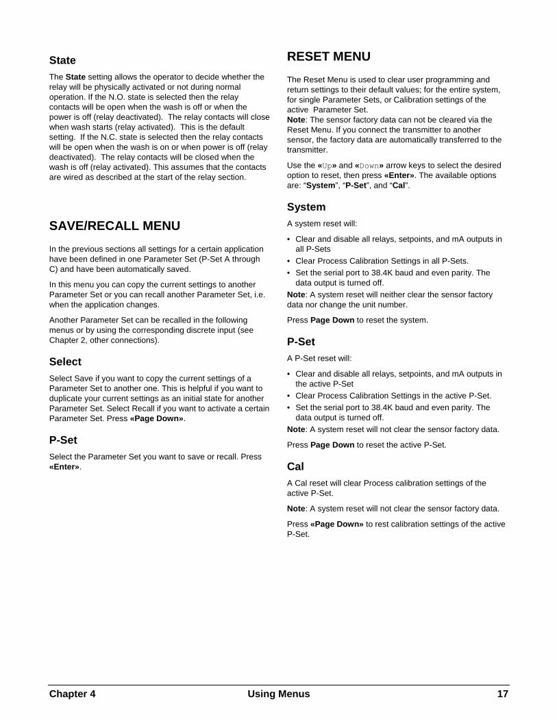
ERROR MESSAGES
Following is a list of error messages, their meaning, and possible causes.
Message Meaning / Possible Cause / Proposed Solution
25 Over Range
90 Over Range
DB Over Range
Forward (25°), Sideward (90°), or Direct Beam (0°) signal is too high. The flow-cell is not filled with a liquid.
DB Signal Low The Direct Beam signal is below usable limit. The turbidity is too high or the sensor is not connected.
Temperature critical The ambient and/or process temperature is close to the specified range. Connect air purge.
Temperature too high The ambient and/or process temperature exceed the specified range. No reliable measurement is possible anymore. Connect air purge to the sensor.
Humidity critical The humidity inside the sensor is higher than the normal value.
Humidity too high The humidity inside the sensor exceeded the safe range.
Light source not working The LED has failed. Ship sensor back for repair.
Detector not working The detector has failed. Ship sensor back for repair.
Stray light too high The signals are too high due to high stray light intensity.. Possible causes are if the pipe is not filled or if a sight glass is too close to the sensor head.
Boards not ok Measurement boards are missing, failed, or not properly connected. Ship sensor back for repair.
Measurement range error Auto-gain algorithm out of range or turbidity value out of calibration table.

Chapter 7 Upgrade 25
CHAPTER 7: UPGRADE
UPGRADES
There is software for various functions located in the Trb 8300 D. The need for field upgrade is likely to occur only with the Main Program and Measurement software.
Main program Software Upgrade Over the life of the instrument, it may become desirable to upgrade the main operating software of the Trb 8300 D to a newer version. The main operating software revision number can be displayed by stepping through the menus: Other Menus/Software Revs/Main Program.
The main program software is changed by downloading the new operating file using METTLER TOLEDO Thornton utility program “Trb 8300 Programmer.exe”. It
runs on computers using Windows95 or later and occupies about 0.7 MB of hard disk space.
NOTE: Not all menus of the Trb8300 Programmer are functional—use only those needed for the upgrade as described in the procedure below.
A cable is required with connector for the computer’s RS232 port. Most computers use a DB9 connector as shown. Tinned leads at the other end connect to the Trb 8300 D screw terminals.
Because the memory chip containing operating software also contains extensive instrument calibration data, it is not practical to upgrade software by replacing the memory chip.
Trb 8300 D to computer RS232 port wiring
Procedure 1. Record all the configuration settings and the serial
number of the Trb 8300 D unit being upgraded.
2. Confirm that the Trb 8300 D is configured for communications. Press «Menu (exit)» and use «Up» in Other Menus to display “RS232 Set-up”. Set Baud = 38.4K, Par = Even, Data Output = Off, if they are not already set this way.
3. Connect the Trb 8300 D to the computer RS232 port as shown above.
4. From e-mail or floppy disk, copy the program Trb8300 Programmer.exe and the new Trb 8300 D software file e.g. 43714_14 into a convenient folder or desktop of the computer.
5. Run Trb8300 Programmer.exe by double clicking it in Windows Explorer and ignore any small incidental windows that may open.
6. Click to open ‘Communication’ menu and ‘RS-232 Functions’ and select ‘Gateway Port Set-up’.
7. Select Port—COM 1 (or other port if you are using another).
8. Select Baud Rate—38400.
9. Select Data Bits—8.
10. Select Parity—Even.
11. Uncheck Enable Polling. Leave other settings as found (Flow Control—Xon/Xoff, Stop Bits—1).
12. Click OK and observe ‘Connected’ in the lower border of the window when communications are functioning.
DB9 Connector to computer (view of end of cable that plugs into
computer)
1 5
6 9
1 2 3 4 5 6 7 8 9
10
Trb 8300D TB2 terminals
Ground Receive Transmit

Chapter 7 Upgrade 26
13. Click on the integrated circuit button (Program Unit, 4th from right) on the tool bar.
14. Select Units to Program—One Unit and enter 1 in the box. Leave Unit Type at Main.
15. Click ‘Read’ and locate the new Trb 8300 D software file and click OK. The new software version will be loaded into computer memory.
16. Click ‘Program’. Loading to the Trb 8300 D will take several minutes. Allow to run until 100% is displayed.
17. Restore the serial number of the unit using the appropriate command in section RS232 Communications.
18. Disconnect the RS-232 wiring from the Trb 8300 D.
19. If necessary, reconfigure the unit with the settings recorded in step 1.

Chapter 8 Accessories and Spare Parts 27
CHAPTER 8: ACCESSORIES AND SPARE PARTS
ACCESSORIES
Description Part Number
IP66 field-type enclosure for wall mounting
incl. 5 pcs PG11 cable gland and front door with window Dimensions: H=200, W=250, L=230 mm H=7.87", W=9.84",L=9.10") Material: Stainless steel (1.4304)
52 800 867
RS232 Interface cable 10 m (30 ft.) 58 080 111
Data Acquisition Software package 52 800 929
SPARE/REPLACEMENT PARTS
Description Part Number
10-Terminal plug-in connector (TB2 and TB3) 52 800 251*
6-Terminal plug-in connector (TB5 and TB6) 52 800 252*
Fuse, 0.5 A slow blow, 5 x 20 mm (Littlefuse 215.500 or equivalent) 52 800 253*
Panel mounting screws (6-32 x 7/16”, 4 required) 52 800 254
Screws for front panel (2 required) 52 800 255
Retaining washers for front panel (2 required) 52 800 256
Liquid crystal display module (order mounting standoffs separately) 52 800 257
Display standoffs (4 required for display above) 52 800 258
*Recommended Spare parts

Appendix A Menu Trees 28
APPENDIX A: MENU TREES
MAIN MENU
Appendix B Set-Up Parameter Record 29
PARAMETER SET MENU

Appendix B Set-Up Parameter Record 30
CALIBRATION MENUS

Appendix B Set-Up Parameter Record 31
mA OUTPUTS MENUS

Appendix B Set-Up Parameter Record 32
RELAYS MENUS

Appendix B Set-Up Parameter Record 33
SAVE/RECALL MENUS

Appendix B Set-Up Parameter Record 34
RESET MENUS

Appendix B Set-Up Parameter Record 35
DIAGNOSTICS MENUS

Appendix B Set-Up Parameter Record 36
OTHER MENUS

Appendix B Set-Up Parameter Record 37
APPENDIX B: SET-UP PARAMETER RECORD
MEASUREMENT PARAMETERS RECORD 1/2
Photocopy this form for each Parameter Set programmed into the Trb 8300 D.
Unit Name: Date:
Sensor installed:
Model: S/N:
Cable length:
Parameter Set:
Units: Name:
Calibration routine : Calibration Solution:
Date of last calibration:
Analog Output 1
Output Type: Range:
On failure set output to 22 mA:
Analog Output 2
Output Type: Range:
On failure set output to 22 mA:
Analog Output 3
Output Type: Range:
On failure set output to 22 mA:
Analog Output 4
Output Type: Range:
On failure set output to 22 mA:
Filter: HOLD mode:
Limit Value 1:
Value: Delay:
Hysteresis: Setpoint :
State:
Limit Value 2
Value: Delay:
Hysteresis: Setpoint :
State:

Appendix B Set-Up Parameter Record 38
MEASUREMENT PARAMETERS RECORD 2/2
Wash contact:
Interval: Wash time:
State:
Alarm:
Delay: State:
Use alarm if mA outputs are under/over range:
Passwords
Master: User1:
User2:
Language:
RS232 Settings
Baud: Parity:
Data output: Output time:
Unit adress:
Appendix C Specifications 39
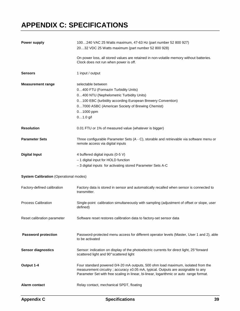
APPENDIX C: SPECIFICATIONS
Power supply 100…240 VAC 25 Watts maximum, 47-63 Hz (part number 52 800 927)
20…32 VDC 25 Watts maximum (part number 52 800 928)
On power loss, all stored values are retained in non-volatile memory without batteries. Clock does not run when power is off.
Sensors 1 input / output
Measurement range selectable between
0…400 FTU (Formazin Turbidity Units)
0…400 NTU (Nephelometric Turbidity Units)
0…100 EBC (turbidity according European Brewery Convention)
0…7000 ASBC (American Society of Brewing Chemist)
0…1000 ppm
0…1.0 g/l
Resolution 0.01 FTU or 1% of measured value (whatever is bigger)
Parameter Sets Three configurable Parameter Sets (A - C), storable and retrievable via software menu or remote access via digital inputs
Digital Input 4 buffered digital inputs (0-5 V)
– 1 digital input for HOLD function
– 3 digital inputs for activating stored Parameter Sets A-C
System Calibration (Operational modes)
Factory-defined calibration Factory data is stored in sensor and automatically recalled when sensor is connected to transmitter.
Process Calibration Single-point calibration simultaneously with sampling (adjustment of offset or slope, user defined)
Reset calibration parameter Software reset restores calibration data to factory-set sensor data
Password protection Password-protected menu access for different operator levels (Master, User 1 and 2), able to be activated
Sensor diagnostics Sensor: indication on display of the photoelectric currents for direct light, 25° forward scattered light and 90° scattered light
Output 1-4 Four standard powered 0/4-20 mA outputs, 500 ohm load maximum, isolated from the measurement circuitry ; accuracy ±0.05 mA, typical. Outputs are assignable to any Parameter Set with free scaling in linear, bi-linear, logarithmic or auto range format.
Alarm contact Relay contact, mechanical SPDT, floating

Appendix C Specifications 40
Contact capacity AC< 250 V/< 5 A DC< 30 V/< 5A
Contact function N/C (fail-safe type)
Alarm delay 000…600 s
Wash contact Relay contact, mechanical SPDT, floating
Contact capacity AC< 250 V/< 5 A DC< 30 V/< 5A
Contact function N/O or N/C
Cleaning interval 0.0 ... 999.9 h (0.0 h = cleaning function switched off)
Duration of cleaning 000...600 s
Limit values (2) 2 relay contacts, mechanical SPDT, floating
Contact capacity AC< 250 V/< 5 A DC< 30 V/< 5A
Contact function N/O or N/C
Delay 000…600 s
Switching points hi-hi / hi-lo / lo-lo
Hysteresis 0.0...50.0%
Digital interface For updating of main program soft ware and for printing of instrument configurations
RS232 standard max. cable length 15 m (45 ft)
Baud rate 1200, 2400, 4800, 9600, 19.2k and 38.4k
Parity odd, even or none
Display Liquid crystal display (LCD), 20 alphanumerical characters x 4 line, backlit
Keypad 20 keys, membrane type keypad
Language software selectable: English, German, or French for menu and Help texts
Diagnostic functions Sensor mA outputs Display Keypad Meter Serial Port Relays Self-test ISM
Data retention Configuration and calibration data in non-battery supported, non-volatile memory
CE
Emissions EN 55022:1994 Class A ITE emissions.
Immunity EN 61326:1997 Measurement, Control and Laboratory Equipment EMC Requirements –
Industrial Use Safety EN61010-1:2001 Safety requirements for electrical equipment for measurement,
control and laboratory use

Appendix C Specifications 41
US UL UL61010B-1 Electrical Measuring and Test Equipment
CAN / CSA C22.2, No. 1010.1
Nominal operating conditions
Ambient temperature –10…+55 °C (14 ... 131 °F)
Transport/Storage temp –20…+80 °C (-4 ... 176 °F)
Relative humidity 0…80 % up to 31 °C (88 °F), linea r decline to 50 % at 40°C (122 °F)
Enclosure
Alloy ABS-PC, UV and chemically resistant
Assembly Panel mounting, cutout 96 x 96 mm (3.78“ x 3.78“)1/4 DIN
Dimensions H 125 mm, W 114 mm, L 162 mm (H 4.92“, W 4.50, L 6.39“)
Protectiom sealed face, IP65 (Nema 4X)
Weight Approx. 0.9 kg (2 lbs.)

Appendix D Ratings 42
APPENDIX D: RATINGS
Declaration of Conformity
We,
Declare under our sole responsibility that the product:
Trb 8300 D Transmitter
to which this declaration relates, is in conformity with the following European, harmonized and published standards at the date of this declaration:
Emissions:
EN 55022:1994 Class A ITE emissions.
Immunity: EN 61326:1997 Measurement, Control and Laboratory Equipment EMC
Requirements – Industrial Use Safety:
EN61010-1:2001 “Safety requirements for electrical equipment for measurement, control and laboratory use” incorporating Amendments Nos. 1 & 2.
Testing for compliance was carried out to the following specifications:
Following the provisions of the directives 89/336/EEC Electromagnetic Compatibility
Amendment to the above directive: 93/68/EEC
Low Voltage. Directive 73/23/EEC
Amendment to the above directive: 93/68/EEC
UL Recognition Mettler-Toledo Thornton, 36 Middlesex Turnpike, Bedford, MA 01730, USA has obtained Underwriters Laboratories’ Recognition for Trb 8300 D Transmitters. They bear the cULUS recognition mark, signifying that the products have been evaluated to the applicable ANSI/UL and CSA Standards for use in the U.S. and Canada. US UL UL61010B-1 Electrical Measuring and Test Equipment CAN/CSA C22.2, No. 1010.1

Appendix E Warranty 43
APPENDIX E: WARRANTY
METTLER TOLEDO guarantees the quality of materials and workmanship within a narrow range of manufacturing tolerances, so that the product purchased is free from any substantial deviations from material and manufacturing quality standards. The warranty is valid for the period of one year from date of delivery ex works. If within this warranty period, any repair or replacement should become necessary, and such cause is not due to misuse or incorrect application, please return the product, carriage paid, to your appropriate METTLER TOLEDO agency. Repair work will be carried out free of charge. Final decision on whether the defect is due to a manufacturing error or to incorrect operation of the product by the customer is made at the option of the Customer Service department of METTLER TOLEDO. After expiry of the period of warranty, faulty products will be repaired or replaced on an exchange basis against payment of the costs involved.

BR Mettler-Toledo Ind. e Com. Ltda., Alameda Araguaia, 451 - Alphaville, BR – 06455-000 Barueri / SP, Brazil
Tel. +55 11 4166 74 00, Fax +55 11 4166 74 01
CH Mettler-Toledo (Schweiz) GmbH, Im Langacher, CH – 8606 Greifensee, Switzerland Tel. 044 944 45 45, Fax 01 944 45 10
D Mettler-Toledo GmbH, Prozeßanalytik, Ockerweg 3, D – 35396 Gießen, Germany Tel. (0641) 507-333, Fax (0641) 507-397
F Mettler-Toledo Analyse Industrielle Sàrl, 30 Bld. de Douaumont, BP 949, F – 75829 Paris, France Tel. (1) 47 37 0600, Fax (1) 47 37 4626
USA Mettler-Toledo Ingold, Inc., 36 Middlesex Turnpike, Bedford, MA 01730 USA Tel. (781) 301-8800, Fax (781) 271-0681
Mettler-Toledo AG, Process Analytics, Industrie Nord, CH – 8902 Urdorf, Tel. +41 44 729 62 11, Fax +41 44 729 66 36, www.mtpro.com Subject to technical changes. 08 / 06 © Mettler-Toledo AG. Printed in USA. 52 800 987