Embed Size (px)
Citation preview

TURBINE BURNERS: Engine Performance Improvements; Mixing, Ignition, and Flame-Holding
in High Acceleration Flows
Presented by William A. Sirignano Mechanical and Aerospace Engineering University of California< Irvine
Research performed in collaboration with F. Liu, D. Dunn-Rankin, B. Colcord, S. Puranam, F. Cheng, I. Kim , X. Fang, C. Mehring , J. Cai , O. Icoz
Supported by the NSF, AFOSR, and the California Energy Commission

OBJECTIVES Analyze the thermodynamic advantages of augmentative combustion during the expansion through the turbine for turbojet , turbofan , and stationary - power gas - turbine engines. Study combustion in accelerating , transonic mixing layers.
Perform computational and experimental research on accelerating, turning transonic reacting flow. Examine the use of cavities for flameholding Contribute to the development of a new technology. Identify relevant scientific and technological challenges. Three SBIR awards were made by AFRL following our first two papers showing potential performance gains.

TURBOFAN CYCLE

Weakness of Conventional Engines
• Contention of TSFC & ST
amST
T=
ΤfmTSFC
=ST
TSFC SIZE/WEIGHT
Range highly
undesirable
Desirable
Not Good

TURBINE BURNER CONCEPT
Turbine burning has advantage in a temperature - limited system; many stator burners approach continuous burner.

TURBOJET PERFORMANCE VS. COMPRESSION RATIO
M = 2 , T 4 = 1500 K , T 6 = 1900 K

TURBOJET FUEL CONSUMPTION VS. THRUST
M = 2 , T 4 = 1500 K , T 6 = 1900 K

TURBOJET PERFORMANCE VS. MACH NUMBER
π c = 40 , T 4 = 1500 K , T 6 = 1900 K

TURBOFAN PERFORMANCE VS. FAN BYPASS RATIO
M = 0.87 , T 4 = 1500 K , T 6 = 1900 K , π c = 40

NEW OPPORTUNITIES WITH TURBINE BURNERS
Increased thrust for same size or same thrust at smaller size compared to engine without augmentation. At higher compression ratios or flight Mach numbers , higher thrust than afterburner engines
Less fuel consumption at higher compression ratio and / or flight Mach number. Better fuel consumption than afterburner case throughout parameter range
For stationary power , higher power and efficiency
Lower NOx formation due to lower temperature
Potentially lower take - off noise compared to afterburner

TURBINE PASSAGE FLOW
Flow accelerates through transonic range and turns ; streamwise and transverse accelerations can be O ( 10 5 g )
105 g

CHALLENGES Ignition in a high acceleration flow.
Flame-holding in a high acceleration flow. Combustion with short residence times. Burning of liquid fuels under these conditions. Hydrodynamic stability of stratified flow with large transverse pressure gradient. Modification of aerodynamic loading on turbine blades. Increased heating of critical components.
105 g
105 g

REACTING FLOW STUDIES > Laminar Mixing-Layer Flows – axial acceleration; b.l. approx. > Turbulent Mixing-Layer Flows – axial acceleration; b.l. approx., RANS
equations: algebraic and two-equation models. > Straight and Curved 2-D Channel Flows – axial and transverse
acceleration; RANS equations. > 2-D Turbine- Passage Flows -- axial and transverse acceleration; RANS
equations. > 2-D, Unsteady Channel Flows – axial acceleration of mixing flows in transition. > 2-D and 3-D, Unsteady Channel Flows with Cavities - Injection and
mixing flows in transition. Current computational studies; experimental work completed.

REACTING MIXING LAYER
dp / dx < 0

COMPARISON WITH SIMILAR SOLUTION : TEMPERATURE
β = 2 ; K =1.673 ; ξ = 2 , 3 , 4

VELOCITY PROFILE
Case 1

VELOCITY PROFILES AND MACH NUMBER CONTOURS
Flow accelerates from subsonic to supersonic; Mach number is lower in hot , high - velocity region.
Lighter density portion of flow accelerates faster with overshoot developing. Note that u∞ increases with x.

Curved Channel: Reacting, Accelerating Mixing Layer with Faster Fluid on the Outside
Temperature Vorticity
• Compared to the non-accelerating case, the formation of large eddies by pairing is delayed. The streamwise accelaration has a stabilizing effect.
• The combustion region curves slight inward due to varying pressure gradient.
• Compared to the non-accelerating case, the formation of large eddies by pairing is delayed. The streamwise accelaration has a stabilizing effect.
• The combustion region curves slight inward due to varying pressure gradient.

Converging-diverging Curved Channel: Reacting, Accelerating Mixing Layer with Faster Fluid on the Outside
Temperature


Experimental Test Section
main air flow
fuel injection ports
Shallow cavity: L/D=3 length=5cm width=10cm
thermocouples
- Cavity on the inner and outer curvature - Two aspect ratios: L/D=1 and L/D=3

Cavity top wall
Channel/cavity interface
Channel bottom wall
Fuel flow rate = 10 Liters/min
At higher Re the flow is more turbulent, fuel-air mixing is enhanced and more fuel is burnt in the cavity
Temperature [K]
Tran
sver
se d
ista
nce
[mm
] Temperature measurements
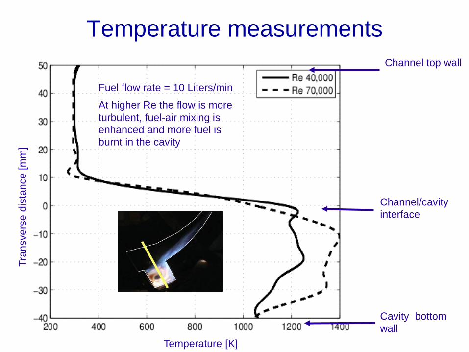
Cavity bottom wall
Channel/cavity interface
Channel top wall
Fuel flow rate = 10 Liters/min
At higher Re the flow is more turbulent, fuel-air mixing is enhanced and more fuel is burnt in the cavity
Tran
sver
se d
ista
nce
[mm
]
Temperature [K]
Temperature measurements

Temperature measurements
Length [mm] Width [mm]
300
500
Condition: - Shallow cavity - Counterflow injection - Air: Re 70,000 - Fuel: 10 Liters/min
O2: 19.3 % CO: +500 ppm
O2: 20.9 % CO: 10 ppm
The flame is along the two side walls of the cavity. The flame is not symmetric due to the presence of the pyrex window.

Experimental Observations
Combustion with liquid fuel (heptane):
Combustion stable at Re 40,000 and 70,000 only if the shallow cavity is used. With a deep cavity the mixing is not sufficient and the heptane droplet evaporation doesn’t occur as efficiently. Fuel, and therefore the flame, penetrate farther into the main stream with liquid injection.

Recent DNS Studies Background and Motivation Numerical method
− OpenFOAM
2D unsteady results − Effects of injection configuration
3D unsteady results − Mesh
− Effects of injection configuration
Conclusions Future Work

Cavity and injection stability
Re = 2000, no injection, steady
Re = 950, 10% mass injection, unsteady
No cavity
•Steady at Re = 105
Cavity without injection
•Steady at Re = 2000
•Unsteady at Re = 3000
Cavity with injection
•Steady at Re = 900
•Unsteady at Re = 950
•Injection into quiescent field is steady at Re = 1000

Rossiter Modes
1nfL n CStU ξ κ
−= =
+
2112
M
Mξ
γ=
−+
κ = Ratio of shear layer to freestream velocity
C = Correction factor ≈ 0.2
• Rossiter modes occur only for cold flow without injection in deep cavities. These modes are not seen with injection into cavity, shallow cavities, and / or reacting flow

Effect of Reynolds Number
• Inlet Reynolds number = 500
• 6% increase in amount of fuel burned due to increased residence time
• Inlet Reynolds number = 2000
• Flame becomes unsteady
• 91% increase in amount of fuel burned due to turbulent mixing

Effect of Injection Configuration
• Inlet Reynolds number = 1000 with downstream injection
• 30% decrease in amount of fuel burned
• Inlet Reynolds number = 1000 with extra air injection into cavity
• Second flame produced
• 9% increase in amount of fuel burned

OpenFOAM
Open source C++ libraries for CFD Top-level code is a direct representation of the equations.
Continuum formulation is input without stating difference form.
becomes: solve ( fvm::ddt(rho, U) + fvm::div(phi, U) -
fvm::laplacian(mu, U) == - fvc::grad(p) );
Uses reactingFoam solver with one-step reaction:
Westbrook-Dryer chemical kinetics rate: /a uE R Ta b a b
F F OA Y Y eω ρ −+= −
( )7 16 2 2 2 2 211 3.76 7 8 41.36C H O N CO H O N+ + → + +
( ) ( ) ( )U
UU U ptρ
ρ µ∂
+∇ • −∇ • ∇ = −∇∂

Burning Efficiency 0
0
, ,
,
1 t TF in F out
cF int
m mdt
T mη
+ −= ∫
where is the fuel mass flow rate into or out of the system Fm
start-up period
Fuel mass flow rates for a cavity with L/D = 2.0 at Re = 5000.

Mixedness Mixedness is defined locally as:
− yi is a modified mass fraction:
− YC = mass fraction of carbon atoms − YN = mass fraction of nitrogen atoms − yC + yN = 1
− yi,m is the perfectly mixed modified mass fraction of element i
− m is used to enforce a mixedness of zero if completely unmixed for either YN or YC approaching zero:
ii
C N
Yy
Y Y=
+
( ) ( ), ,21 C C m N N my y y y
Mm
− −= +
, ,
, ,
,,
C m C C m
N m C C m
y Y Ym
y Y Y<
= >

Injection Configurations Vitiated air in channel (50% combustion
products) 25% overall equivalence ratio 3 configurations with additional air injection

Comparison of 2D Injection Configurations 2:1 aspect ratio cavity at Re = 10000
Parallel injection has highest burning efficiency in 2D representation
Efficiency not converged after 0.2s or 12 channel residence times
Combustion efficiency for different 2D injection configurations

2D Reacting with Reinforcing Injection
Lowest burning efficiency Large vortices are nearly stationary
Velocity vectors and vorticity contours at Re = 10000

2D Reacting with Disrupting Injection Medium burning efficiency Large vortices are nearly stationary
Velocity vectors and vorticity contours at Re = 10000

2D Reacting with Parallel Injection
Highest burning efficiency Much greater vortex interaction
Velocity vectors and vorticity contours at Re = 10000

3D Mesh
Symmetry planes used for efficient calculations
Models periodic array of injectors
Jet size increased for greater mesh resolution
Top of Cavity
Off-jet Symmetry Plane
Jet Symmetry Plane
Fuel / Air Injection Ports

3D Reacting with Disrupting Injection • Slices through cavity at Re = 10000
– Mixedness contours and velocity vectors shown
Jet symmetry plane Off-jet symmetry plane

3D Reacting with Disrupting Injection • Slices along cavity width at Re = 10000
– Mixedness contours and velocity vectors shown
a) x = 0.105 b) x = 0.115 c) x = 0.125 d) x = 0.135 e) x = 0.145

3D Reacting with Reinforcing Injection • Slices through cavity at Re = 10000
– Mixedness contours and velocity vectors shown
Jet symmetry plane Off-jet symmetry plane

3D Reacting with Reinforcing Injection • Slices along cavity width at Re = 10000
– Mixedness contours and velocity vectors shown
a) x = 0.105 b) x = 0.115 c) x = 0.125 d) x = 0.135 e) x = 0.145

Conclusions 2D results show:
− Higher efficiency for parallel injection than for reinforcing or disrupting
− Reinforcing and disrupting injection configurations create almost stationary vortices
− Parallel injection significantly increases vortex interaction
3D results show: − 3D effects are significant
− Reinforcing injection causes higher velocities in the cavity than disrupting injection
− Disrupting injection creates a well-defined area of very high mixedness
− Reinforcing injection creates a larger zone of relatively high mixedness

Future work Work already begun:
− Improved 3D mesh
− Curving channels
− Converging channels
Possible future improvements: − Liquid fuels
− Turbulence modeling for higher Reynolds numbers

Thank You!