Embed Size (px)
Citation preview
Turbomachinery in Biofuel Production
Martin Görling
Licentiate Thesis 2011
KTH Royal Institute of Technology School of Chemical Science and Engineering
Department of Chemical Engineering and Technology Energy Processes
Stockholm, Sweden

Copyright © Martin Görling 2011 All rights reserved
Printed in Sweden Universitetsservice US-AB Stockholm
TRITA-CHE Report 2011-2 ISSN 1654-1081 ISBN 978-91-7415-835-9

I
Abstract
The aim for this study has been to evaluate the integration potential of turbomachinery into
the production processes of biofuels. The focus has been on biofuel produced via biomass
gasification; mainly methanol and synthetic natural gas. The research has been divided into
two parts; gas and steam turbine applications.
Steam power generation has a given role within the fuel production process due to the large
amounts of excess chemical reaction heat. However, large amounts of the steam produced
are used within the production process and is thus not available for power production.
Therefore, this study has been focused on lowering the steam demand in the production
process, in order to increase the power production. One possibility that has been evaluated
is humidification of the gasification agent in order to lower the demand for high quality
steam in the gasifier and replace it with waste heat. The results show that the power
penalty for the gasification process could be lowered by 18-25%, in the specific cases that
have been studied.
Another step in the process that requires a significant amount of steam is the CO2-removal.
This step can be avoided by adding hydrogen in order to convert all carbon into biofuel. This
is also a way to store hydrogen (e.g. from wind energy) together with green carbon. The
results imply that a larger amount of sustainable fuels can be produced from the same
quantity of biomass.
The applications for gas turbines within the biofuel production process are less obvious.
There are large differences between the bio-syngas and natural gas in energy content and
combustion properties which are technical problems when using high efficient modern gas
turbines. This study therefore proposes the integration of a natural gas fired gas turbine; a
hybrid plant. The heat from the fuel production and the heat recovery from the gas turbine
flue gas are used in a joint steam cycle. Simulations of the hybrid cycle in methanol
production have shown good improvements. The total electrical efficiency is increased by
1.4-2.4 percentage points, depending on the fuel mix. The electrical efficiency for the
natural gas used in the hybrid plant is 56-58%, which is in the same range as in large-scale
combined cycle plants. A bio-methanol plant with a hybrid power cycle is consequently a
competitive production route for both biomass and natural gas.
Keywords: Bio-Methanol, Biomass, Gasification, Humidification, Hybrid Cycle, SNG

Turbomachinery in Biofuel Production
II
Table of contents
Abstract ............................................................................................................................ I
Nomenclature ................................................................................................................. III
List of Papers ................................................................................................................... IV
1. Introduction .......................................................................................................... - 1 -
1.1 Background ............................................................................................................. - 1 -
1.2 Aim and Scope ........................................................................................................ - 2 -
1.3 Thesis outline .......................................................................................................... - 3 -
1.4 Method ................................................................................................................... - 3 -
2. Background ........................................................................................................... - 5 -
2.1 Biofuels today and tomorrow ................................................................................. - 5 -
2.2 Future energy combined ........................................................................................ - 6 -
2.3 Fuel production process ......................................................................................... - 9 -
3. Steam turbine simulations and results ................................................................. - 13 -
3.1 Humidification ...................................................................................................... - 13 -
3.2 Hydrogen in biofuel production ........................................................................... - 18 -
4. Gas turbine simulations and results ..................................................................... - 23 -
4.1 Hybrid combined cycle ......................................................................................... - 25 -
5. Discussion ........................................................................................................... - 29 -
6. Conclusions and recommendations for further studies ......................................... - 31 -
6.1 Recommendations for further studies ................................................................. - 31 -
7. Acknowledgement............................................................................................... - 34 -
8. References .......................................................................................................... - 35 -

III
Nomenclature
Abbreviations ASU Air Separation Unit CHP Combined Heat and Power CCR Carbon Capture and Recycling CCS Carbon Capture and Storage DH District Heating DME Dimethyl Ether el electrical (output, efficiency) HP High Pressure IGCC Integrated Gasification Combined Cycle LHV Lower Heating Value LP Low Pressure MeOH Methanol NG Natural Gas nm3 m3 volume at 0°C, 1 atm ref reference SNG Synthetic Natural Gas tot total P Power output (electrical) WGS Water-Gas-Shift Greek letters η Efficiency (NG, el, tot)
Turbomachinery in Biofuel Production
IV
List of Papers
Papers:
I. Görling, M. and Westermark, M., 2010. Increased Power Generation by
Humidification of Gasification Agent in Biofuel Production. World Renewable Energy
Congress 2010
II. Görling, M. and Westermark, M., 2010. Integration of Hybrid Cycles in Bio-Methanol
Production. 23rd International Conference on Efficiency, Cost, Optimization,
Simulation and Environmental Impact of Energy Systems
III. Magnusson, M., Mohseni, F., Görling, M. Alvfors, P., 2010. Introducing Renewable
Electricity to increase Biogas Production Potential. International Conference on
Applied Energy 2010
My contribution to the papers: Paper I and II have been written on my own with supervision by Mats Westermark. In paper III, I was responsible for writing the part concerning gasification (2.2 Gasification) and also contributed to the discussion and conclusion.

1. Introduction
- 1 -
1. Introduction
1.1 Background
To be able to travel and transport products all over the world is something we take for
granted. Yet, the increased interest in the environment has drawn the intention to the
fossil-based transport sector and raised the question; can we keep this path? If the goal is to
eliminate the emission and not the possibility to transport the development of
replacements for today’s fossil fuels that dominates the transportation sector must take
place to slow down the anthropogenic green-house effect as well as providing alternatives
for the shrinking supplies of fossil fuels.
In addition, the use of energy for transportation is predicted to grow by 2% annually (Kahn
Ribeiro et al. 2007), this increase will also need to be met by green alternatives. The share of
renewable energy for road transports was only 1.5% in 2006 (International Energy Agency,
2008). Many countries have high ambitions for the near future, aiming to increase the
renewable share to 10-20%, in year 2010. For most countries, production of renewable fuels
is a way to secure the supply and decrease the dependency on imported oil products. In
Sweden the forest industry is already an important income, as it accounts for 11% of the
total export value (Swedish Forest Agency, 2009). Bio-energy from the forest cannot fulfil
the global demand for transportation energy but will probably be one of a couple solutions.
In the case of Sweden which is a particularly forest rich country, a significant part of the
road transports could be supplied with energy from the forest (Lindfeldt et al., 2010;
Åkerman and Höjer, 2006; Robért et al. 2007).
There are numerous biofuel production routes, from different raw materials, all with
different characteristics of opportunities and limitations. Biofuels are generally divided into
different generations, were the first generation is commercialised; whilst the second and
third are still under development and pilot plant testing. First generation biofuels include
RME from rapeseed oil and biogas from anaerobic digestion of waste. Ethanol made from
sugar and starch is usually also included in the first generation. The common denominator
of these fuels is that they are produced from organic material without chemical processing.
The production of the second generation of biofuels involves thermal or chemical treatment
Turbomachinery in Biofuel Production
- 2 -
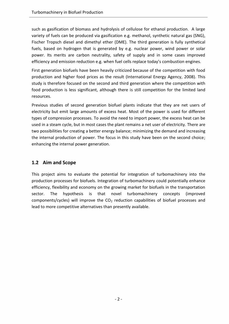
such as gasification of biomass and hydrolysis of cellulose for ethanol production. A large
variety of fuels can be produced via gasification e.g. methanol, synthetic natural gas (SNG),
Fischer Tropsch diesel and dimethyl ether (DME). The third generation is fully synthetical
fuels, based on hydrogen that is generated by e.g. nuclear power, wind power or solar
power. Its merits are carbon neutrality, safety of supply and in some cases improved
efficiency and emission reduction e.g. when fuel cells replace today’s combustion engines.
First generation biofuels have been heavily criticized because of the competition with food
production and higher food prices as the result (International Energy Agency, 2008). This
study is therefore focused on the second and third generation where the competition with
food production is less significant, although there is still competition for the limited land
resources.
Previous studies of second generation biofuel plants indicate that they are net users of
electricity but emit large amounts of excess heat. Most of the power is used for different
types of compression processes. To avoid the need to import power, the excess heat can be
used in a steam cycle, but in most cases the plant remains a net user of electricity. There are
two possibilities for creating a better energy balance; minimizing the demand and increasing
the internal production of power. The focus in this study have been on the second choice;
enhancing the internal power generation.
1.2 Aim and Scope
This project aims to evaluate the potential for integration of turbomachinery into the
production processes for biofuels. Integration of turbomachinery could potentially enhance
efficiency, flexibility and economy on the growing market for biofuels in the transportation
sector. The hypothesis is that novel turbomachinery concepts (improved
components/cycles) will improve the CO2 reduction capabilities of biofuel processes and
lead to more competitive alternatives than presently available.
- 3 -
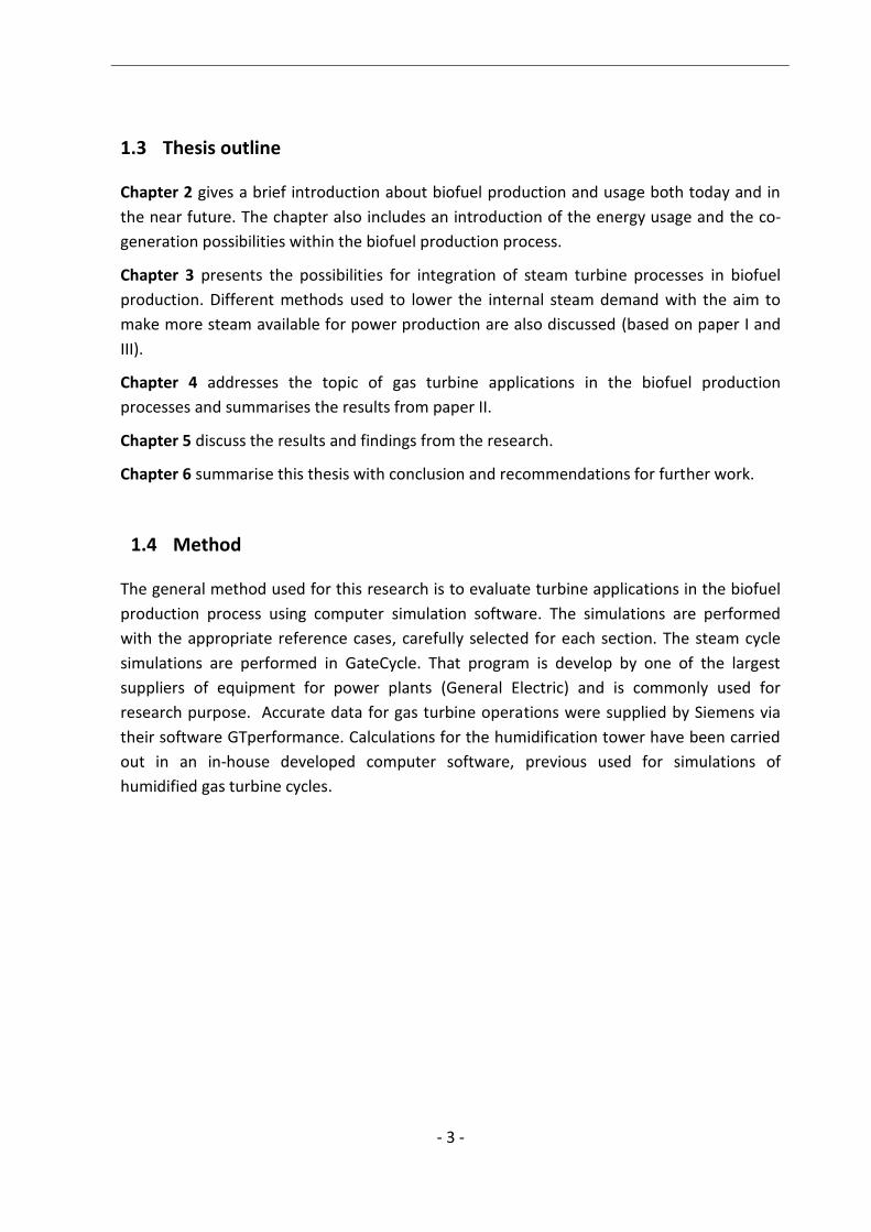
1.3 Thesis outline
Chapter 2 gives a brief introduction about biofuel production and usage both today and in
the near future. The chapter also includes an introduction of the energy usage and the co-
generation possibilities within the biofuel production process.
Chapter 3 presents the possibilities for integration of steam turbine processes in biofuel
production. Different methods used to lower the internal steam demand with the aim to
make more steam available for power production are also discussed (based on paper I and
III).
Chapter 4 addresses the topic of gas turbine applications in the biofuel production
processes and summarises the results from paper II.
Chapter 5 discuss the results and findings from the research.
Chapter 6 summarise this thesis with conclusion and recommendations for further work.
1.4 Method
The general method used for this research is to evaluate turbine applications in the biofuel
production process using computer simulation software. The simulations are performed
with the appropriate reference cases, carefully selected for each section. The steam cycle
simulations are performed in GateCycle. That program is develop by one of the largest
suppliers of equipment for power plants (General Electric) and is commonly used for
research purpose. Accurate data for gas turbine operations were supplied by Siemens via
their software GTperformance. Calculations for the humidification tower have been carried
out in an in-house developed computer software, previous used for simulations of
humidified gas turbine cycles.

Turbomachinery in Biofuel Production
- 4 -
2. Background
- 5 -
2. Background
2.1 Biofuels today and tomorrow
The market for transportation fuel is dominated by fossil fuels like all the other energy
markets. Within the EU, transportation on average stands for 20% of the greenhouse gas
emissions. The EU has therefore set out in their 2020 targets, to reach the target for the
transportation sector the share of biofuels should be increased to 10% of the total energy
usage. In Sweden the CO2 emissions from traffic is approximately 30% of the total CO2
emissions. That’s above the EU average and is partly due to the low CO2 emissions in heat
and power production. Only a tiny portion (approx. 4%) of the transportation fuel used in
Sweden today is biofuel (Swedish Energy Agency, 2008).
An important aspect that often is forgotten is the market penetration barriers for new
biofuels. Today there is an extensive distribution network for gasoline and diesel, and to
some extent ethanol. An entirely new distribution system for fuel would be very costly to
build and it would therefore be advantageous if biofuels could be used in the currently
available infrastructure. Cars sold today are expected to be driven on our roads for the
coming 15 years. Consequently, it will take a long time until all cars will be replaced. The
phasing in of new cars has been slow in the event of a "chicken or the egg” dilemma. If no
fuel stations sell biofuels; it is difficult to sell adapted cars and vice versa. One way to
overcome this problem is to blend in biofuels in today's fossil fuels. Sweden has a policy in
favour of ethanol, which is the explanation to the rapid growth. Furthermore, the most
growing biofuel in recent years is FAME blended into diesel (Swedish Energy Agency, 2008).
For liquid fuels the most interesting biofuel are those which can be blended with fossil
gasoline and used in the cars sold today. Proponents of methanol claim that a few tens of
percent methanol can be blended into gasoline without problems (Karlberg, 2007). Ecotrafik
(Ecotraffic ERD3 AB and Atrax AB, 2007) writes in a report to the Ministry of Enterprise,
Energy and Communications that increased amount of blend in may be a way to achieve
environmental objectives in the short term; but the problem is the limited production of
biofuels. As a result of the postponed entrance of the hydrogen economy, the attention has
been diverted more towards methanol as a replacement for oil and gas (Olah et al., 2006).
Turbomachinery in Biofuel Production
- 6 -
2.2 Future energy combined
The Swedish research program Elforsk (Thunman et al., 2008) have done a comprehensive
report regarding the production of biofuels combined with traditional heat and power
production. That report covers both simple products such as pellets which is commercial
today, but also non-commercial biofuels (SNG, DME and methanol). The study also
concluded that biofuels suitable for vehicles received efficiency in the range of 45-55% with
the exception of methane (SNG) via gasification which could obtain a 60-65% yield1. Cost
estimates indicate that the cost of the biofuel produced is between 2.5 to 3.5 times higher
than the feedstock cost. The fuel that received the highest yield is SNG produced in an
indirect gasifier, whilst methanol gives highest yield among the liquid fuels.
Sweden together with EU has adopted the 20-20 goals, which means that 20% of the energy
should be renewable by the year 2020. To find a replacement for the fuel in the transport
sector has been a problem for a long time and the sector has therefore received a more
moderate goal, 10% renewable in year 2020. The Swedish usage for transportation energy is
130 TWh/y (Swedish Energy Agency, 2009), which implies that there is a need for 13 TWh/y
biofuels to reach the 10% goal without taking the growth in demand into account. The
demand for transportation fuel has steadily increased in recent years, so when we reach
year 2020 the demand may be even higher. On the other hand, future cars will most
certainly be more efficient and thereby use less energy.
The size of a biofuel production facility depends on, among others, available biomass
resources, the markets for the products, district heating and economies of scale. A study
(Thunman et al., 2008) regarding the suitable plant size indicates that methane with a lower
investment cost may be more suitable in smaller scale (50-300MW product) whilst
production of methanol requires a larger plant (100-1000MW product) to reach economical
feasibility. This conclusion is also supported by another study (Sørensen, 2005), stating that
the cost of the produced methanol decreases sharply as the plant size increases (starting at
a biomass input 10MWHHV), but the price trend flattens out (still decreasing) when the
biomass input reaches 200MWHHV.
1 The yield is defined as LHV of product divided with the LHV of the biomass input on wet basis (50% moisture content).
2. Background
- 7 -
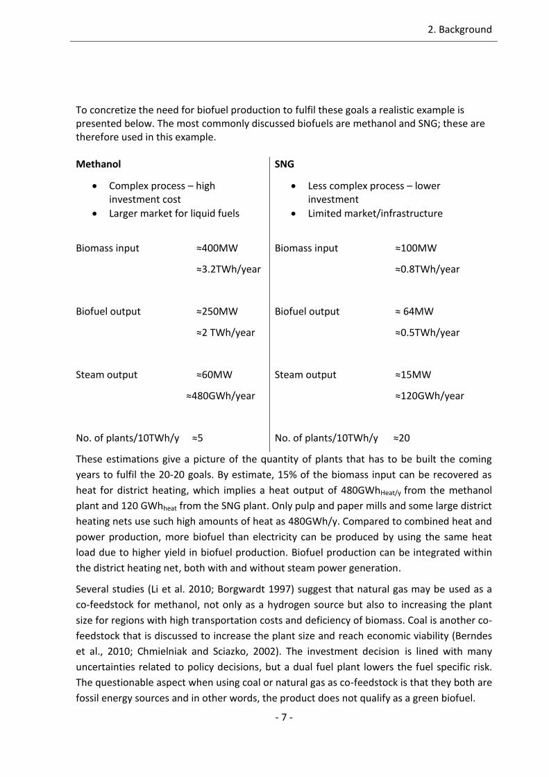
To concretize the need for biofuel production to fulfil these goals a realistic example is presented below. The most commonly discussed biofuels are methanol and SNG; these are therefore used in this example. Methanol
Complex process – high investment cost
Larger market for liquid fuels
Biomass input ≈400MW
≈3.2TWh/year
Biofuel output ≈250MW
≈2 TWh/year
Steam output ≈60MW
≈480GWh/year
No. of plants/10TWh/y ≈5
SNG
Less complex process – lower investment
Limited market/infrastructure
Biomass input ≈100MW
≈0.8TWh/year
Biofuel output ≈ 64MW
≈0.5TWh/year
Steam output ≈15MW
≈120GWh/year
No. of plants/10TWh/y ≈20
These estimations give a picture of the quantity of plants that has to be built the coming
years to fulfil the 20-20 goals. By estimate, 15% of the biomass input can be recovered as
heat for district heating, which implies a heat output of 480GWhHeat/y from the methanol
plant and 120 GWhheat from the SNG plant. Only pulp and paper mills and some large district
heating nets use such high amounts of heat as 480GWh/y. Compared to combined heat and
power production, more biofuel than electricity can be produced by using the same heat
load due to higher yield in biofuel production. Biofuel production can be integrated within
the district heating net, both with and without steam power generation.
Several studies (Li et al. 2010; Borgwardt 1997) suggest that natural gas may be used as a
co-feedstock for methanol, not only as a hydrogen source but also to increasing the plant
size for regions with high transportation costs and deficiency of biomass. Coal is another co-
feedstock that is discussed to increase the plant size and reach economic viability (Berndes
et al., 2010; Chmielniak and Sciazko, 2002). The investment decision is lined with many
uncertainties related to policy decisions, but a dual fuel plant lowers the fuel specific risk.
The questionable aspect when using coal or natural gas as co-feedstock is that they both are
fossil energy sources and in other words, the product does not qualify as a green biofuel.

Turbomachinery in Biofuel Production
- 8 -
2.2.1 Opportunities within the district heating net
The overall efficiency of the biofuel production is to a large extent dependant on how the
excess heat can be recovered; that’s where district heating comes into the picture. District
heating has a number of strategic advantages including the possibility of using industrial
waste heat, combined heat power generation and excess heat from biofuel production.
Larger plants are also able to handle fuels that can be difficult for individual home owners to
handle; such as municipal waste which requires a crucial flue gas cleaning process.
Today there are about 35 combined heat and power (CHP) plants in Sweden. The remaining
part of the heat is produced in hot water boilers (except a small amount of waste heat from
industry) without co-production of electricity. Among these plants, there are about 40 units
which have an annual heat supply above 100 GWh/year and another 30 plants exceeding 50
GWh/year (Svensk Fjärrvärme, 2009). A major disadvantage of district heating is the large
variation in demand depending on the seasons. During the summer (May-September) only
the heat to generate tap water is provided which gives a relatively small heat load.
Co-generation of biofuel production has been evaluated both on regional (Börjesson and
Ahlgren, 2010; Difs et al., 2010) and national scale (Egeskog et al., 2009). To reach the EU
2020 targets, about 15% of the available heat sink in the district heating net must be used
for combined biofuel and heat production plants, assuming that all fuel is produced via this
route (Egeskog et al., 2009). Furthermore, combined biofuel and heat production plants are
thus not competitive with CHP plants without additional subsidiaries for fuel production
(Börjesson and Ahlgren 2010; Wetterlund and Söderström 2010). A study conducted by
(Leduc et al., 2009) shows that the specific cost of producing methanol from biomass could
be reduced by 10% if the waste heat could be sold as district heating. Thus, the problem
with the varying heat load still remains. A biofuel production plant (with district heating co-
generation) would be a massive investment which requires continuous operation to
decrease the payback period. Accordingly, the plant size must be chosen to fit the district
heating base load.
The district heating distribution net is like the electrical grid, a natural monopoly since it is
not economically feasible to build more than one net. As opposed to the electrical grid; the
net owner and heat producer are usually the same company. This lack of competition has
proven to be a problem for companies that want to deliver (excess) heat to the district
heating network; known as third party access. Third party access has been the topic for
numerous governmental investigations (Statens Offentliga Utredningar, 2005) and the
Swedish Competition Authority (Konkurrensverket, 2009). The only decision that has been
made is that the net owner has the obligation to negotiate with companies that requests
third party accesses. If access is not granted, the net owner has to motivate the decision
(Ministry of Enterprise, Energy and Communications, 2008).

2. Background
- 9 -
2.3 Fuel production process
To give an overall picture of the potential for integration of turbomachinery a short
presentation of the biofuel production process in general as well as the energy use in SNG
production will be given. The background chapter also provides an explanation as to why
some topics have been chosen for deeper studies and others rejected at an early stage.
The general production process for biofuels is shown in figure 1. The process is to a large
extent the same for all biofuels, except for the synthesis and gas treatment steps.
Figure 1 : General fuel production process
Pre-treatment is the first step and involves chipping and drying of the biomass. The received
biomass has a moister content of 30-60 wt%, after drying a moister content of 10-15%wt is
preferable (Fagernäs et al., 2010). There are methods such as pyrolysis and pelletizing to
increase the energy density in order to facilitate long distance transportation. The pre-
treatment requirements are highly dependent on the choice of gasifier.
In the gasification step the biomass is heated and turned into gas via partial oxidation with a
gasification agent present. There are several different types of gasifiers; most of them based
on fluidised bed technique (Olofsson et al., 2005). Therefore, the gasification agent also has
the important function of fluidizing the bed. Different gasification agents are (air, steam,
oxygen or hydrogen) used depending on the gasifier type and the required product. The
produced gas is called syngas and primarily contains carbon monoxide, hydrogen and
carbon dioxide. Air is rarely suggested for fuel production purposes since the nitrogen
dilutes the syngas; which influences the downstream process.
The gasification is followed by gas cleaning where the primary objective is to protect the
downstream process equipment. The most common pollutants are sulphur and alkali metals
that inhibits the catalysts. There are different possible cleaning routs suggested depending
on the syngas temperature and pressure (Hamelinck and Faaij, 2002). The syngas cleaning
technology is still under development with focus on an advanced hot process that would
enhance the efficiency (Sharma et al., 2008). Cold gas cleaning is a proven and more reliable
technique, but it is associated with heat loss since the syngas must be reheated, before the
synthesis step.
Turbomachinery in Biofuel Production
- 10 -
Gas treatment, also known as gas conditioning, comprises water gas shifting (WGS) and
methane reforming. Steam is added in the WGS in order to shift carbon monoxide to
hydrogen and carbon dioxide. The reaction is exothermic and the temperature level of the
reaction heat is around 200°C.
WGS: CO+H2O ↔ CO2 + H2 -41 MJ/kmol (Ahmed and Gupta, 2009)
This step is done to increase the proportion of hydrogen in the gas before the fuel synthesis.
There is always a shortage of hydrogen in the raw syngas and hydrogen is thus the limiting
reactant in the fuel synthesis from biomass.
Fuel synthesis differs a lot depending on which fuel being produced. The process is typically
exothermic, pressurized and occurs at elevated temperatures (e.g. 30bar, 300°C).
Upgrading involves CO2 separation in the case of SNG production. In Methanol/DME
production distillation is required to remove water from the product. Production of liquid
fuels gives a by-product; the off-gas. The content of the off-gas depends on the conversion
and recirculation rates in the synthesis step but is mainly CO2 and vapour (and also N2 if the
gasification medium is air).
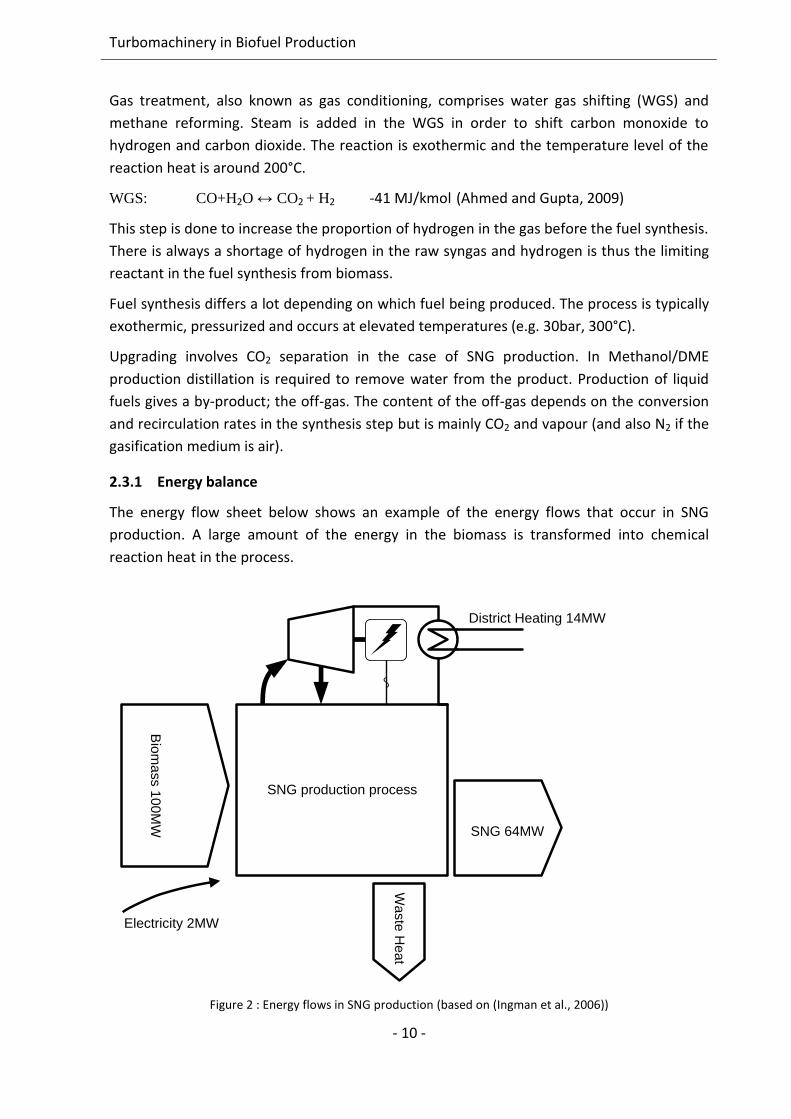
2.3.1 Energy balance
The energy flow sheet below shows an example of the energy flows that occur in SNG
production. A large amount of the energy in the biomass is transformed into chemical
reaction heat in the process.
Bio
ma
ss 1
00
MW
Electricity 2MW
SNG 64MW
SNG production process
Wa
ste
He
at
District Heating 14MW
Figure 2 : Energy flows in SNG production (based on (Ingman et al., 2006))
2. Background
- 11 -
Excess heat is used to produce steam for internal use and for export to a steam cycle; in this
case 5MW of the raw syngas is used for steam superheating. The internal power production
is 5 MW, but additional 2 MW of external power is still needed. External power is needed to
power the compression processes; oxygen production and pressurized fuel feeding.
Condensation heat from the steam cycle can be used for district heating; in this case
14MWth (Ingman et al., 2006).
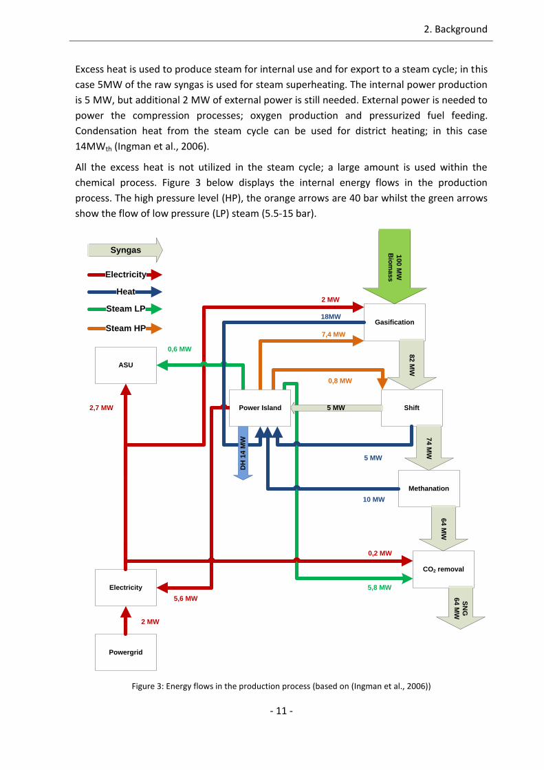
All the excess heat is not utilized in the steam cycle; a large amount is used within the
chemical process. Figure 3 below displays the internal energy flows in the production
process. The high pressure level (HP), the orange arrows are 40 bar whilst the green arrows
show the flow of low pressure (LP) steam (5.5-15 bar).
10
0 M
W
Bio
ma
ss
Gasification
82
MW
Shift
74
MW
Methanation
64
MW
CO2 removal
SN
G
64
MW
ASU
Electricity
Powergrid
2 MW
5 MW2,7 MW
5,6 MW
2 MW
0,2 MW
0,6 MW
7,4 MW
0,8 MW
5,8 MW
18MW
10 MW
5 MW
Electricity
Heat
Steam LP
Steam HP
SyngasD
H 1
4 M
W
Power Island
Figure 3: Energy flows in the production process (based on (Ingman et al., 2006))
Turbomachinery in Biofuel Production
- 12 -
The flow sheet on the previous page clearly shows the energy usage in the process. The
power island is an important section used to recover heat, produce electricity and also
supply heat to the other processes. The main objective when designing the steam system is
to supply the demand at the lowest possible exergy cost, e.g. expand the steam to the right
pressure/temperature before it is used as process steam. If the pressure level for the
demand can be reduced the power production will increase.
2.3.2 Energy consumers
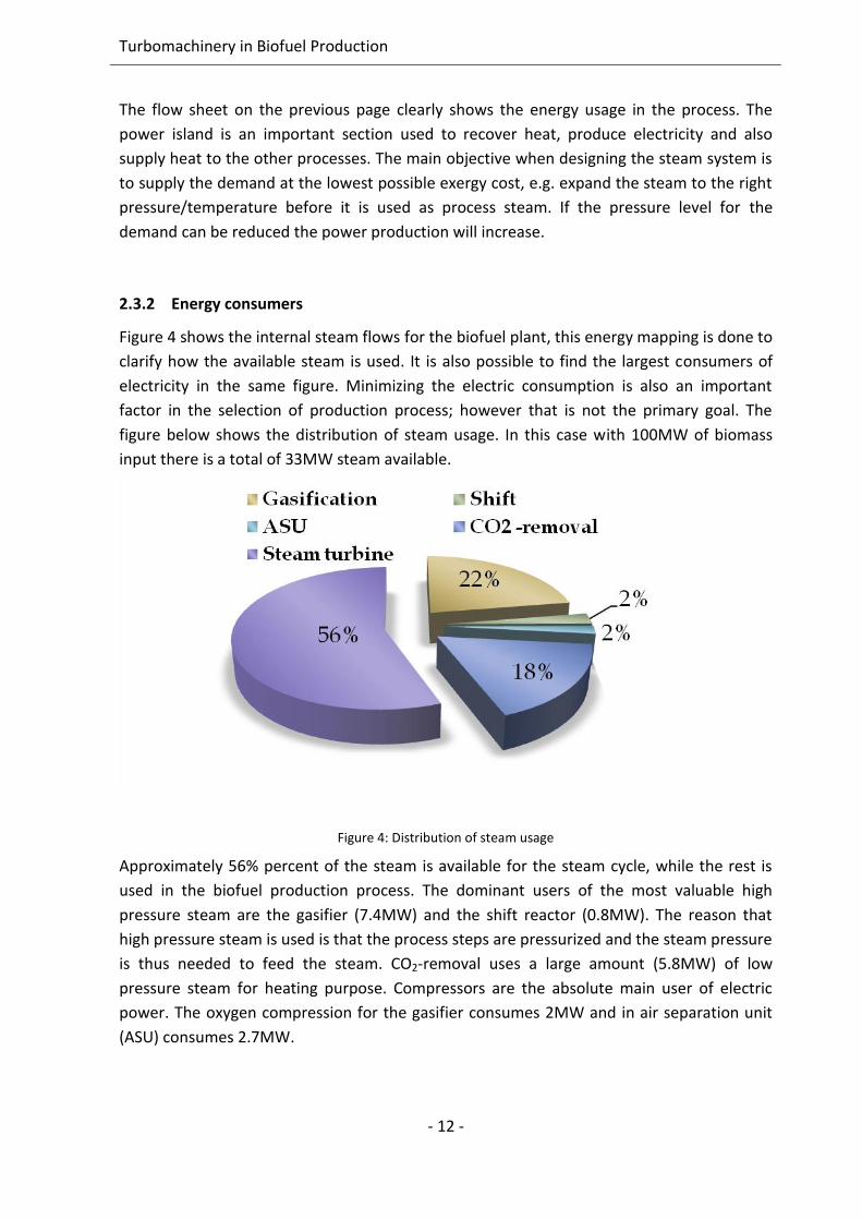
Figure 4 shows the internal steam flows for the biofuel plant, this energy mapping is done to
clarify how the available steam is used. It is also possible to find the largest consumers of
electricity in the same figure. Minimizing the electric consumption is also an important
factor in the selection of production process; however that is not the primary goal. The
figure below shows the distribution of steam usage. In this case with 100MW of biomass
input there is a total of 33MW steam available.
Figure 4: Distribution of steam usage
Approximately 56% percent of the steam is available for the steam cycle, while the rest is
used in the biofuel production process. The dominant users of the most valuable high
pressure steam are the gasifier (7.4MW) and the shift reactor (0.8MW). The reason that
high pressure steam is used is that the process steps are pressurized and the steam pressure
is thus needed to feed the steam. CO2-removal uses a large amount (5.8MW) of low
pressure steam for heating purpose. Compressors are the absolute main user of electric
power. The oxygen compression for the gasifier consumes 2MW and in air separation unit
(ASU) consumes 2.7MW.
3. Steam turbine simulations and results
- 13 -
3. Steam turbine simulations and results
The rational use of excess heat from the fuel production process is essential for both
efficiency and economy. The large amount of excess heat above 200°C is suitable for use in
steam cycles as well as for process steam and/or district heating production. Biofuel
production is therefore an obvious opportunity for poly-generation of biofuel, electricity
and heat.
The energy mapping shows that about 50% of the excess heat is needed within the biofuel
production process, which is a setback for the electricity production. By reducing the
internal steam demand, more steam becomes available for power production. The
hypothesis used is that the largest energy savings can be made by reducing the demands
from the largest users, especially the valuable high pressure steam. Energy mapping showed
that the largest steam consumers are the gasifier and the CO2 removal step.
One method to lower the steam demand and also to reduce the steam pressure for the
gasification process is to humidify the gasification agent (oxygen/air). By using
humidification the high pressure steam can be replaced by steam at reduced pressure and
also by waste heat recovered from humid gases.
This study also discusses two possible techniques to lower the energy used for CO2 removal
and increased the yield of biofuel by using hydrogen as co-feedstock. Both of these
processes need hydrogen which is suggested to originate from renewable electricity.
3.1 Humidification
There is a wide range of atmospheric humidification applications; such as cooling towers
and air conditioning. Humidification of pressurized air is suggested in gas turbine
applications where the heat in the exhaust gas is used to humidify the combustion air after
compression and thereby increase the gas turbine flow without any additional compression
power (Bartlett, 2002; Jonsson and Yan, 2005; Rydstrand et al., 2002; Dalili and
Westermark, 1998).
Turbomachinery in Biofuel Production
- 14 -
Humidification of gasification media has been identified as an alternative to using steam at a
lower pressure or using waste heat from different internal streams (e.g. condensation of
humid gases or waste heat from the biomass dryer). The humidification can be performed in
stages and at different partial pressures to adjust to external waste heat sources and to
different process integration alternatives. There might be other methods to reduce the
steam demand and decrease the amount of steam needed for the gasification processes.
However, this study focuses on the efficiency improvements by humidifiers and hence the
vapour flow to the gasifier is assumed to remain unchanged, although supplied in a more
efficient way.
In a humidifier; counter current contact between a water film and a gas is possible. The gas
will transport some of the water as vapour even if the gas temperature is below the water
boiling temperature. This is the same phenomenon that is used every day when drying
laundry. The driving force for this process is the difference in vapour activity at the water
film (partial pressure of water) (Dalili, 2003). By using the humidification technique a major
part of the energy can be supplied at temperature levels well below the boiling point.
There are several reasons to use water vapour in the gasification process. The vapour
lowers the partial pressure of carbon monoxide and thereby decreases the risk for
deposition of solid coal. The risk for coal deposition increases with the pressure which
implies a higher rate of water at higher operation pressure. Vapour is also an important
component to fluidizing the bed. Furthermore, if the goal is to produce hydrogen, a high
rate of water vapour is preferable.
When cooling down a humid gas, water will condensate at a sliding temperature; hence the
latent heat will be released at a sliding temperature. The evaporation of water in the
humidification process occurs in the same way, which makes it favourable to combine these
two, quite similar processes, without the intermediate step, with steam production.
A humidification application has been studied for two cases of SNG production. The heat for
humidification is taken both from steam extraction at reduced pressure and from heat
recovery from the dehumidification step. Water vapour in the produced gas after the
methanation has to be removed in the upgrading process; this is done by cooling and
condensation. Before upgrading, the partial condensation of vapour could be used for pre-
humidification purpose. This allows an exchange of humidity without the significant exergy
losses associated with steam production. The conventional way to recover latent heat by
steam production has the drawback that steam generation demands dew point
temperatures over the boiling point meanwhile the energy only can be utilized below the
boiling point. As mentioned previously, other available waste heat sources and humid
streams can be used.
In order to quantify the effects of the suggested methods a power penalty has been
calculated for each case. The power penalty is an estimation of the quantity of electricity
that could be produced if the steam for the gasifier instead was used in the steam cycle.
3. Steam turbine simulations and results
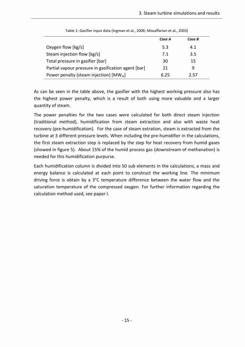
- 15 -
Table 1: Gasifier input data (Ingman et al., 2006; Mozaffarian et al., 2003)
Case A Case B
Oxygen flow [kg/s] 5.3 4.1
Steam injection flow [kg/s] 7.1 3.5
Total pressure in gasifier [bar] 30 15
Partial vapour pressure in gasification agent [bar] 21 9
Power penalty (steam injection) [MWel] 6.25 2.57
As can be seen in the table above, the gasifier with the highest working pressure also has
the highest power penalty, which is a result of both using more valuable and a larger
quantity of steam.
The power penalties for the two cases were calculated for both direct steam injection
(traditional method), humidification from steam extraction and also with waste heat
recovery (pre-humidification). For the case of steam extration, steam is extracted from the
turbine at 3 different pressure levels. When including the pre-humidifier in the calculations,
the first steam extraction step is replaced by the step for heat recovery from humid gases
(showed in figure 5). About 15% of the humid process gas (downstream of methanation) is
needed for this humidification purpurse.
Each humidification column is divided into 50 sub elements in the calculations, a mass and
energy balance is calculated at each point to construct the working line. The minimum
driving force is obtain by a 3°C temperature difference between the water flow and the
saturation temperature of the compressed oxygen. For further information regarding the
calculation method used, see paper I.

Turbomachinery in Biofuel Production
- 16 -
Humidified Oxygen
HP Steam
Oxygen
MP Steam
Condensate
Humid process
stream downstream
of methanation
Partially condensed
process stream to SNG
upgrading
Feed Water
1
A
C
D
2
E
F
3
4
B
Figure 5: Schematic sketch of humidification equipment, including pre-humidifier
3. Steam turbine simulations and results
- 17 -
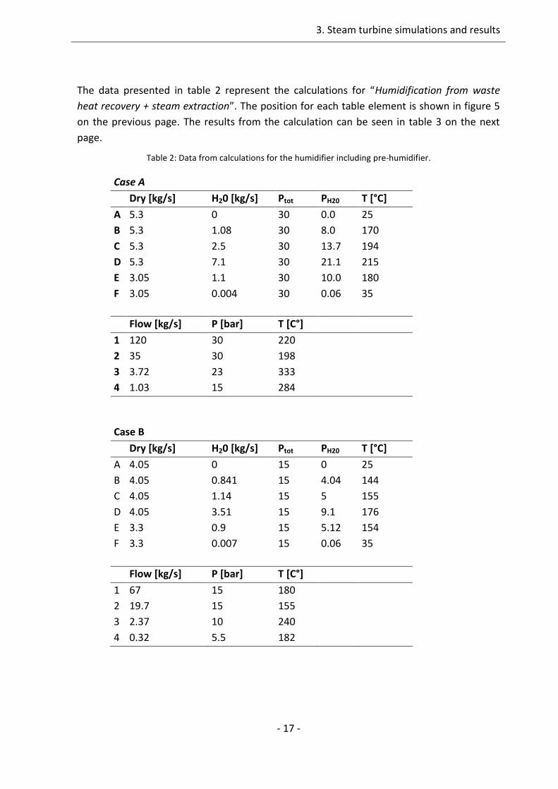
The data presented in table 2 represent the calculations for “Humidification from waste
heat recovery + steam extraction”. The position for each table element is shown in figure 5
on the previous page. The results from the calculation can be seen in table 3 on the next
page.
Table 2: Data from calculations for the humidifier including pre-humidifier.
Case A
Dry [kg/s] H20 [kg/s] Ptot PH20 T [°C]
A 5.3 0 30 0.0 25
B 5.3 1.08 30 8.0 170
C 5.3 2.5 30 13.7 194
D 5.3 7.1 30 21.1 215
E 3.05 1.1 30 10.0 180
F 3.05 0.004 30 0.06 35
Flow [kg/s] P [bar] T [C°]
1 120 30 220
2 35 30 198
3 3.72 23 333
4 1.03 15 284
Case B
Dry [kg/s] H20 [kg/s] Ptot PH20 T [°C]
A 4.05 0 15 0 25
B 4.05 0.841 15 4.04 144
C 4.05 1.14 15 5 155
D 4.05 3.51 15 9.1 176
E 3.3 0.9 15 5.12 154
F 3.3 0.007 15 0.06 35
Flow [kg/s] P [bar] T [C°]
1 67 15 180
2 19.7 15 155
3 2.37 10 240
4 0.32 5.5 182
Turbomachinery in Biofuel Production
- 18 -
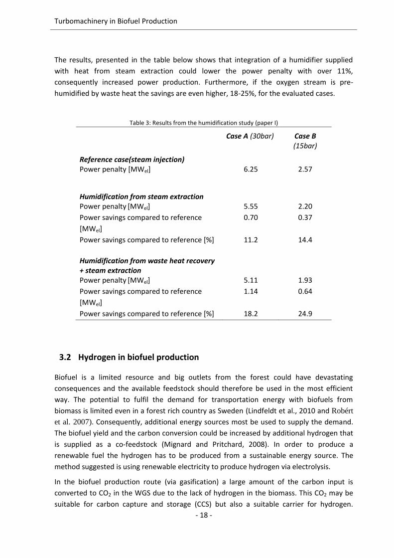
The results, presented in the table below shows that integration of a humidifier supplied
with heat from steam extraction could lower the power penalty with over 11%,
consequently increased power production. Furthermore, if the oxygen stream is pre-
humidified by waste heat the savings are even higher, 18-25%, for the evaluated cases.
Table 3: Results from the humidification study (paper I)
Case A (30bar) Case B (15bar)
Reference case(steam injection) Power penalty [MWel] 6.25 2.57
Humidification from steam extraction Power penalty [MWel] 5.55 2.20
Power savings compared to reference
[MWel]
0.70 0.37
Power savings compared to reference [%] 11.2 14.4
Humidification from waste heat recovery + steam extraction
Power penalty [MWel] 5.11 1.93
Power savings compared to reference
[MWel]
1.14 0.64
Power savings compared to reference [%] 18.2 24.9
3.2 Hydrogen in biofuel production
Biofuel is a limited resource and big outlets from the forest could have devastating
consequences and the available feedstock should therefore be used in the most efficient
way. The potential to fulfil the demand for transportation energy with biofuels from
biomass is limited even in a forest rich country as Sweden (Lindfeldt et al., 2010 and Robért
et al. 2007). Consequently, additional energy sources most be used to supply the demand.
The biofuel yield and the carbon conversion could be increased by additional hydrogen that
is supplied as a co-feedstock (Mignard and Pritchard, 2008). In order to produce a
renewable fuel the hydrogen has to be produced from a sustainable energy source. The
method suggested is using renewable electricity to produce hydrogen via electrolysis.
In the biofuel production route (via gasification) a large amount of the carbon input is
converted to CO2 in the WGS due to the lack of hydrogen in the biomass. This CO2 may be
suitable for carbon capture and storage (CCS) but also a suitable carrier for hydrogen.
3. Steam turbine simulations and results
- 19 -
Adding hydrogen produced from green power would increase the quantity of biofuels
generated from the same amount of biomass. Wind and solar power are the green energy
sources that have been given the greatest future potential. A problem with these energy
sources is the non-controllable power output; the power production is entirely controlled by
the weather. Hydrogen production through electrolysis, used as a variable load together
with hydrogen storage can be a method for rational use of the fluctuations in power output
from these intermittent green power sources.
Transportation and storage of hydrogen gas as a transportation fuel needs a new
infrastructure that hasn’t been widely realized yet. One main drawback of hydrogen storage
is that a significant compression work is needed. The compression work needed for biogas is
less significant since biogas contains more than 3 times more energy per volume than
hydrogen. The chemical conversion of hydrogen and bio-energy together into biofuels could
be an interim solution that utilizes the distribution infrastructure for natural gas and biogas
or liquid fuels.
The two integration possibilities that are studied and compared are:
Hydrogasification
Gasification combined with Sabatier reaction
In hydrogasification, the hydrogen is used as the gasification agent and thereby eliminates
both the WGS-process and the CO2-removal. When combining the Sabatier reaction with
gasification, the removed CO2 is used for further production of methane (SNG). The
difference between the two methods is where in the process hydrogen is added. These two
methods are further presented in the next two chapters followed by a comparison.
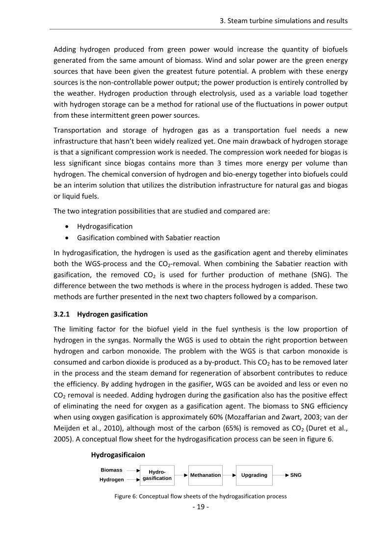
3.2.1 Hydrogen gasification
The limiting factor for the biofuel yield in the fuel synthesis is the low proportion of
hydrogen in the syngas. Normally the WGS is used to obtain the right proportion between
hydrogen and carbon monoxide. The problem with the WGS is that carbon monoxide is
consumed and carbon dioxide is produced as a by-product. This CO2 has to be removed later
in the process and the steam demand for regeneration of absorbent contributes to reduce
the efficiency. By adding hydrogen in the gasifier, WGS can be avoided and less or even no
CO2 removal is needed. Adding hydrogen during the gasification also has the positive effect
of eliminating the need for oxygen as a gasification agent. The biomass to SNG efficiency
when using oxygen gasification is approximately 60% (Mozaffarian and Zwart, 2003; van der
Meijden et al., 2010), although most of the carbon (65%) is removed as CO2 (Duret et al.,
2005). A conceptual flow sheet for the hydrogasification process can be seen in figure 6.
Hydro-
gasificationMethanation Upgrading SNG
Biomass
Hydrogen
Hydrogasificaion
Figure 6: Conceptual flow sheets of the hydrogasification process
Turbomachinery in Biofuel Production
- 20 -
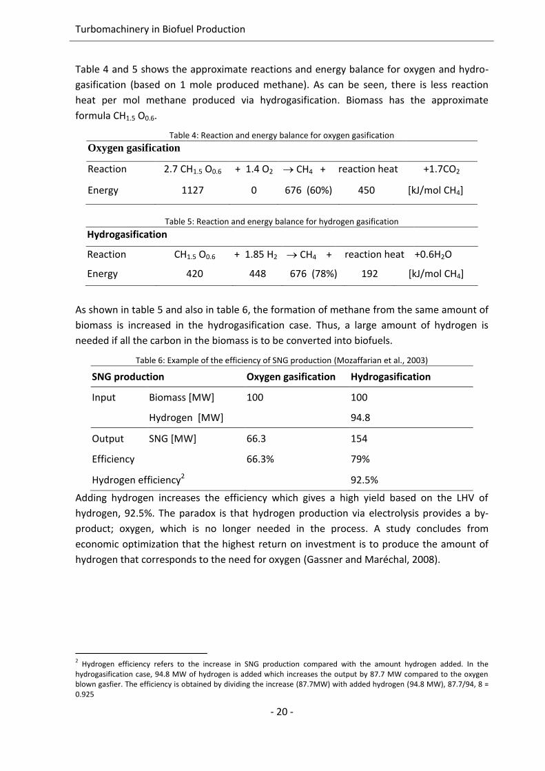
Table 4 and 5 shows the approximate reactions and energy balance for oxygen and hydro-
gasification (based on 1 mole produced methane). As can be seen, there is less reaction
heat per mol methane produced via hydrogasification. Biomass has the approximate
formula CH1.5 O0.6.
Table 4: Reaction and energy balance for oxygen gasification
Oxygen gasification
Reaction 2.7 CH1.5 O0.6 + 1.4 O2 CH4 + reaction heat +1.7CO2
Energy 1127 0 676 (60%) 450 [kJ/mol CH4]
Table 5: Reaction and energy balance for hydrogen gasification
Hydrogasification
Reaction CH1.5 O0.6 + 1.85 H2 CH4 + reaction heat +0.6H2O
Energy 420 448 676 (78%) 192 [kJ/mol CH4]
As shown in table 5 and also in table 6, the formation of methane from the same amount of
biomass is increased in the hydrogasification case. Thus, a large amount of hydrogen is
needed if all the carbon in the biomass is to be converted into biofuels.
Table 6: Example of the efficiency of SNG production (Mozaffarian et al., 2003)
SNG production Oxygen gasification Hydrogasification
Input Biomass [MW] 100 100
Hydrogen [MW] 94.8
Output SNG [MW] 66.3 154
Efficiency 66.3% 79%
Hydrogen efficiency2 92.5%
Adding hydrogen increases the efficiency which gives a high yield based on the LHV of
hydrogen, 92.5%. The paradox is that hydrogen production via electrolysis provides a by-
product; oxygen, which is no longer needed in the process. A study concludes from
economic optimization that the highest return on investment is to produce the amount of
hydrogen that corresponds to the need for oxygen (Gassner and Maréchal, 2008).
2 Hydrogen efficiency refers to the increase in SNG production compared with the amount hydrogen added. In the
hydrogasification case, 94.8 MW of hydrogen is added which increases the output by 87.7 MW compared to the oxygen blown gasfier. The efficiency is obtained by dividing the increase (87.7MW) with added hydrogen (94.8 MW), 87.7/94, 8 = 0.925

3. Steam turbine simulations and results
- 21 -
3.2.2 CO2 utilization and CCR
As mentioned earlier, a significant amount of the carbon input in the biofuel production
process is converted to CO2 and needs to be separated. To increase the biogas production,
this green CO2 could be used for production of additional SNG using the well-known
Sabatier reaction. A conceptual flow sheet of the suggested process can be seen below.
Gasification WGS Methanation Upgrading
BiogasCO2
Biomass
Oxygen
Sabatier
reactorHydrogen
Gasification combined with the Sabatier reaction
Figure 7: Conceptual flow sheets of oxygen gasification combined with the Sabatier reaction (paper III)
The formation of methane in the Sabatier reactor proceeds according to the Sabatier
reaction:
CO2 + 4H2 CH4 + 2H2O ∆H=-165kJ/mol Eq. 1
As the reaction formula shows, the reaction is exothermal and produces two molecules of
water for each methane molecule. The reaction could be run at temperatures between 250-
400°C. Hence, the reaction heat could be recovered and be useful for steam production.
Table 7 below shows the mass balance for oxygen gasification combined with the Sabatier
reaction. As can be seen more than half of the carbon input is removed as carbon dioxide in
the upgrading step.
Table 7: Potential for increased SNG production by using the Sabatier reaction (input [Mozaffarian et al., 2003], output from calculations in paper III)
Gasification Biomass H2 CO2 CH4
In (mol) 100 (mol C) -
Out (mol) 0.7 54 36
Sabatier
In (mol) 217 54
Out (mol) 22 5.4 49
Total output 22.7 5.4 85
By using additional hydrogen the SNG yield can be raised with 140% from the same amount
of biomass. Reusing carbon in such a manner reduces the need for fossil methane as well as
supplying fuel to the transport sector.
Turbomachinery in Biofuel Production
- 22 -
For more comprehensive information see paper III, that paper also discusses the possibility
to reuse CO2 from biogas production via digestion.
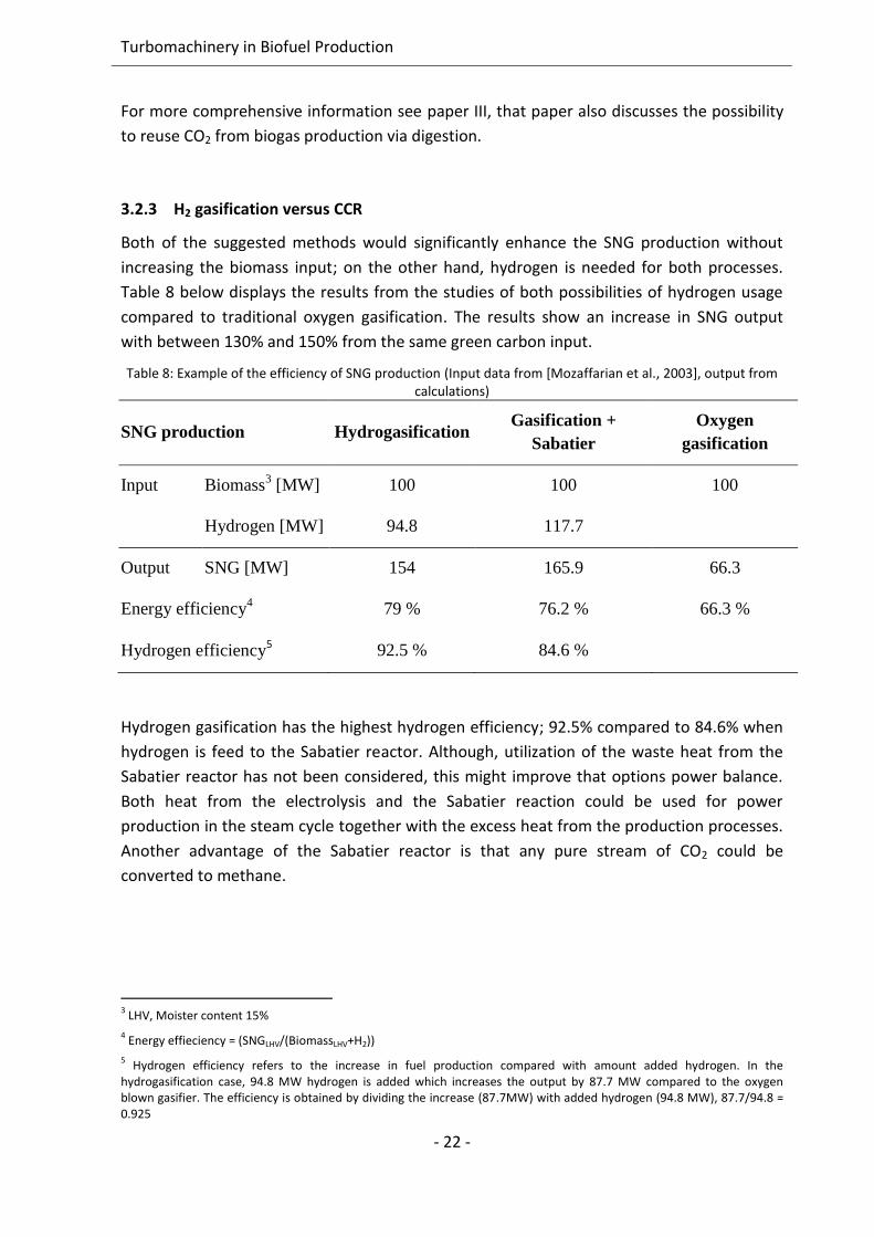
3.2.3 H2 gasification versus CCR
Both of the suggested methods would significantly enhance the SNG production without
increasing the biomass input; on the other hand, hydrogen is needed for both processes.
Table 8 below displays the results from the studies of both possibilities of hydrogen usage
compared to traditional oxygen gasification. The results show an increase in SNG output
with between 130% and 150% from the same green carbon input.
Table 8: Example of the efficiency of SNG production (Input data from [Mozaffarian et al., 2003], output from calculations)
SNG production Hydrogasification Gasification +
Sabatier
Oxygen
gasification
Input Biomass3 [MW] 100 100 100
Hydrogen [MW] 94.8 117.7
Output SNG [MW] 154 165.9 66.3
Energy efficiency4 79 % 76.2 % 66.3 %
Hydrogen efficiency5 92.5 % 84.6 %
Hydrogen gasification has the highest hydrogen efficiency; 92.5% compared to 84.6% when
hydrogen is feed to the Sabatier reactor. Although, utilization of the waste heat from the
Sabatier reactor has not been considered, this might improve that options power balance.
Both heat from the electrolysis and the Sabatier reaction could be used for power
production in the steam cycle together with the excess heat from the production processes.
Another advantage of the Sabatier reactor is that any pure stream of CO2 could be
converted to methane.
3 LHV, Moister content 15%
4 Energy effieciency = (SNGLHV/(BiomassLHV+H2))
5 Hydrogen efficiency refers to the increase in fuel production compared with amount added hydrogen. In the
hydrogasification case, 94.8 MW hydrogen is added which increases the output by 87.7 MW compared to the oxygen blown gasifier. The efficiency is obtained by dividing the increase (87.7MW) with added hydrogen (94.8 MW), 87.7/94.8 = 0.925
4. Gas turbine simulations and results
23
4. Gas turbine simulations and results
An improvement of the overall efficiency due to the implementation of gas turbines in the
biofuel production process is not as obvious as for steam turbines. The raw syngas is very
different from the natural gas which most gas turbines are built and optimized for in terms
of energy content and combustion properties. Furthermore, the composition of the syngas
is dependent on the feedstock, gasification agent and which method being used which
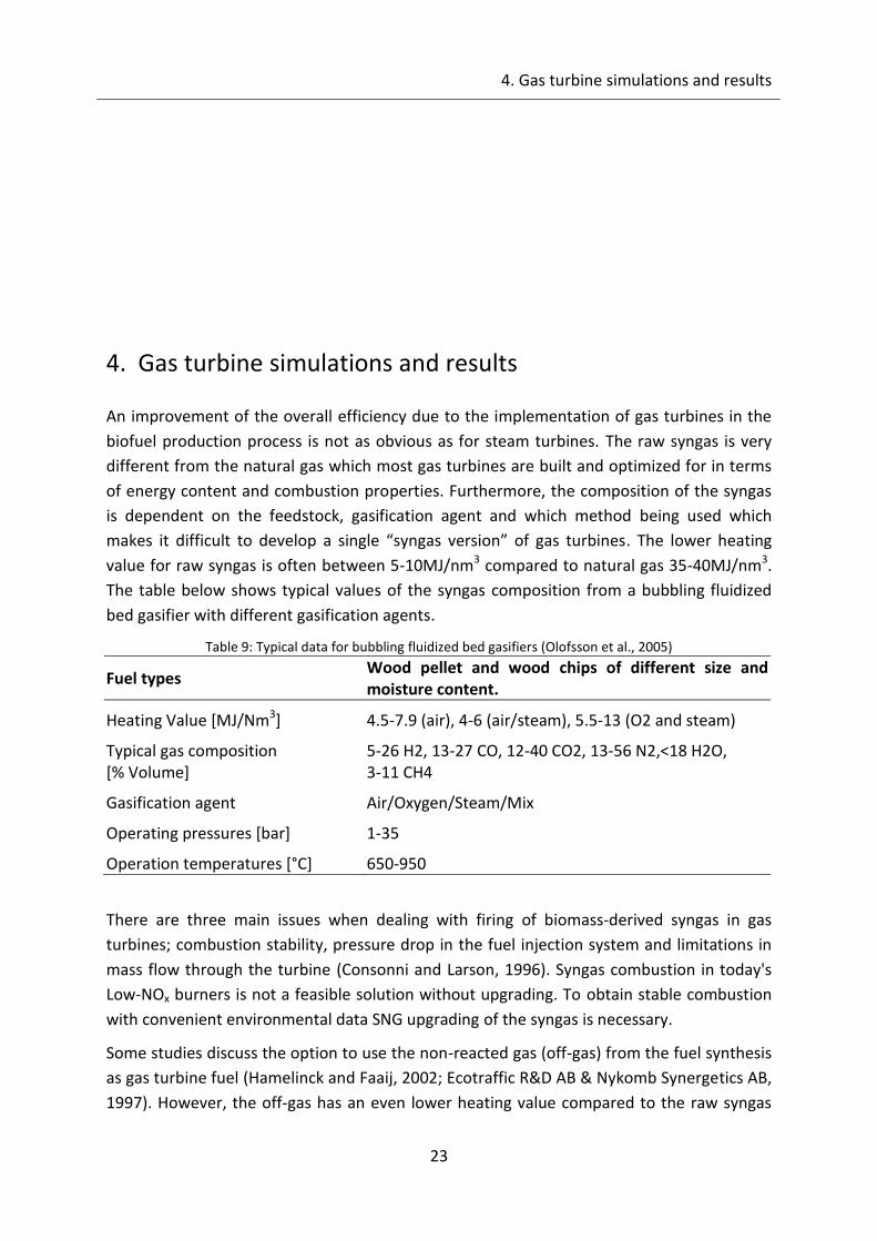
makes it difficult to develop a single “syngas version” of gas turbines. The lower heating
value for raw syngas is often between 5-10MJ/nm3 compared to natural gas 35-40MJ/nm3.
The table below shows typical values of the syngas composition from a bubbling fluidized
bed gasifier with different gasification agents.
Table 9: Typical data for bubbling fluidized bed gasifiers (Olofsson et al., 2005)
Fuel types Wood pellet and wood chips of different size and moisture content.
Heating Value [MJ/Nm3] 4.5-7.9 (air), 4-6 (air/steam), 5.5-13 (O2 and steam)
Typical gas composition [% Volume]
5-26 H2, 13-27 CO, 12-40 CO2, 13-56 N2,<18 H2O, 3-11 CH4
Gasification agent Air/Oxygen/Steam/Mix
Operating pressures [bar] 1-35
Operation temperatures [°C] 650-950
There are three main issues when dealing with firing of biomass-derived syngas in gas
turbines; combustion stability, pressure drop in the fuel injection system and limitations in
mass flow through the turbine (Consonni and Larson, 1996). Syngas combustion in today's
Low-NOx burners is not a feasible solution without upgrading. To obtain stable combustion
with convenient environmental data SNG upgrading of the syngas is necessary.
Some studies discuss the option to use the non-reacted gas (off-gas) from the fuel synthesis
as gas turbine fuel (Hamelinck and Faaij, 2002; Ecotraffic R&D AB & Nykomb Synergetics AB,
1997). However, the off-gas has an even lower heating value compared to the raw syngas
Turbomachinery in Biofuel Production
24
since the combustible components are also used in fuel synthesis. The content of the off-gas
is dependent on how efficient the fuel synthesis is and if the un-reacted gas is re-circulated.
A study on methanol and hydrogen production shows that the off-gas has a heating value
between 4-9MJ/nm3; depending on process design (Hamelinck and Faaij, 2002). The same
study also discusses if these gases are possible turbine fuels and refers to tests carried out
by General Electric. General Electric has achieved stable combustion with a modified turbine
at a heating value as low as 3.7 MJ/Nm3, hydrogen content 8-26% (Consonni and Larson,
1996). But to completely adjust modern gas turbine for syngas combustion a major re-
design of the combustor is needed (Consonni and Larson, 1996).
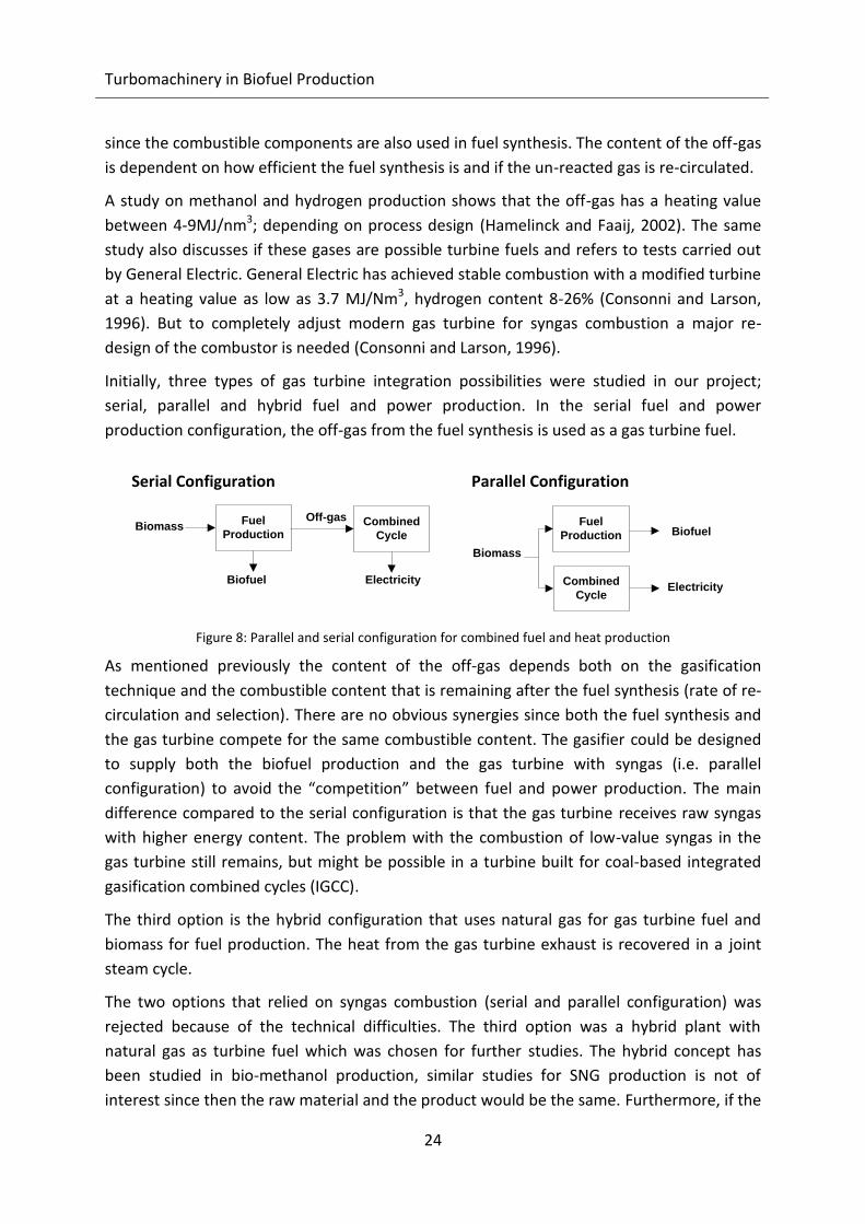
Initially, three types of gas turbine integration possibilities were studied in our project;
serial, parallel and hybrid fuel and power production. In the serial fuel and power
production configuration, the off-gas from the fuel synthesis is used as a gas turbine fuel.
Fuel
ProductionBiomass Combined
Cycle
Biofuel
Serial Configuration
Off-gas
Electricity
Fuel
Production
Biomass
Combined
CycleElectricity
Biofuel
Parallel Configuration
Figure 8: Parallel and serial configuration for combined fuel and heat production
As mentioned previously the content of the off-gas depends both on the gasification
technique and the combustible content that is remaining after the fuel synthesis (rate of re-
circulation and selection). There are no obvious synergies since both the fuel synthesis and
the gas turbine compete for the same combustible content. The gasifier could be designed
to supply both the biofuel production and the gas turbine with syngas (i.e. parallel
configuration) to avoid the “competition” between fuel and power production. The main
difference compared to the serial configuration is that the gas turbine receives raw syngas
with higher energy content. The problem with the combustion of low-value syngas in the
gas turbine still remains, but might be possible in a turbine built for coal-based integrated
gasification combined cycles (IGCC).
The third option is the hybrid configuration that uses natural gas for gas turbine fuel and
biomass for fuel production. The heat from the gas turbine exhaust is recovered in a joint
steam cycle.
The two options that relied on syngas combustion (serial and parallel configuration) was
rejected because of the technical difficulties. The third option was a hybrid plant with
natural gas as turbine fuel which was chosen for further studies. The hybrid concept has
been studied in bio-methanol production, similar studies for SNG production is not of
interest since then the raw material and the product would be the same. Furthermore, if the
4. Gas turbine simulations and results
25
goal is to produce electricity from biomass the most efficient and economic feasible option
should be a biomass fired steam cycle instead of producing SNG for combined cycle power
production. The concept and results from that study is presented in chapter 4.1 and is based
on paper II.
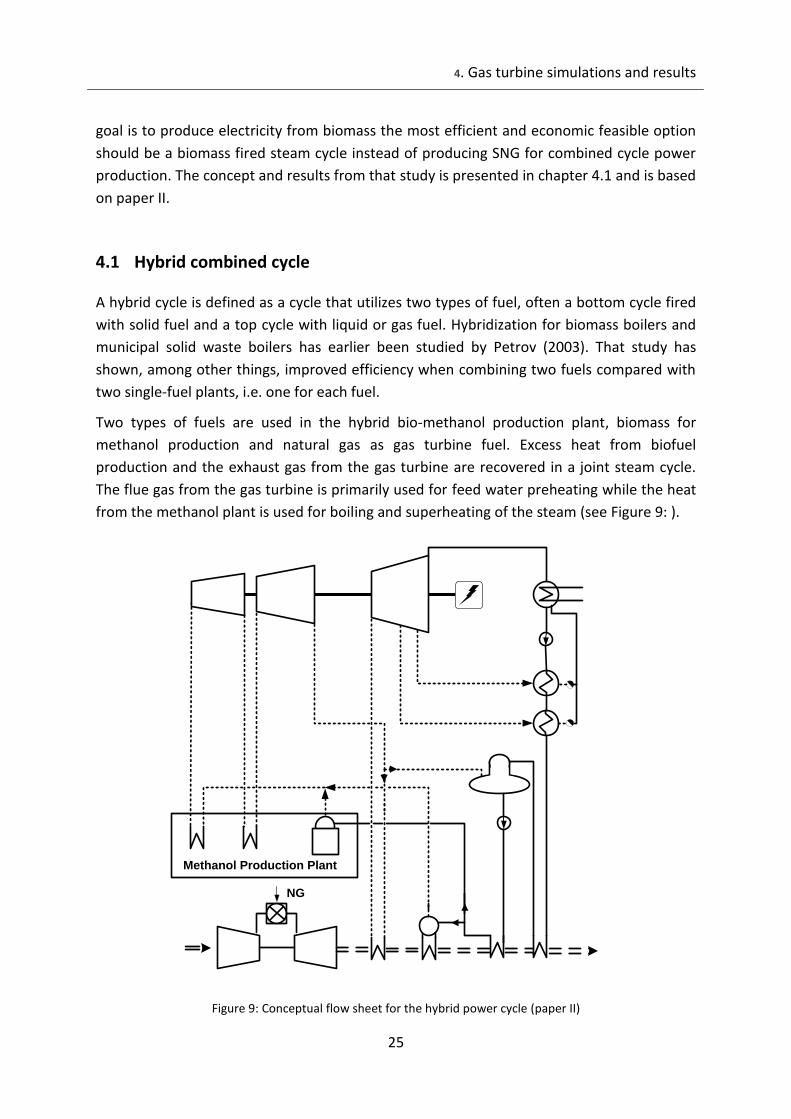
4.1 Hybrid combined cycle
A hybrid cycle is defined as a cycle that utilizes two types of fuel, often a bottom cycle fired
with solid fuel and a top cycle with liquid or gas fuel. Hybridization for biomass boilers and
municipal solid waste boilers has earlier been studied by Petrov (2003). That study has
shown, among other things, improved efficiency when combining two fuels compared with
two single-fuel plants, i.e. one for each fuel.
Two types of fuels are used in the hybrid bio-methanol production plant, biomass for
methanol production and natural gas as gas turbine fuel. Excess heat from biofuel
production and the exhaust gas from the gas turbine are recovered in a joint steam cycle.
The flue gas from the gas turbine is primarily used for feed water preheating while the heat
from the methanol plant is used for boiling and superheating of the steam (see Figure 9: ).
Methanol Production Plant
NG
Figure 9: Conceptual flow sheet for the hybrid power cycle (paper II)
Turbomachinery in Biofuel Production
26
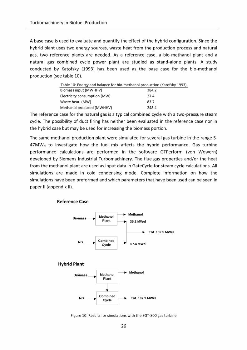
A base case is used to evaluate and quantify the effect of the hybrid configuration. Since the
hybrid plant uses two energy sources, waste heat from the production process and natural
gas, two reference plants are needed. As a reference case, a bio-methanol plant and a
natural gas combined cycle power plant are studied as stand-alone plants. A study
conducted by Katofsky (1993) has been used as the base case for the bio-methanol
production (see table 10).
Table 10: Energy and balance for bio-methanol production (Katofsky 1993)
Biomass input (MWHHV) 384.2
Electricity consumption (MW) 27.4
Waste heat (MW) 83.7
Methanol produced (MWHHV) 248.4
The reference case for the natural gas is a typical combined cycle with a two-pressure steam
cycle. The possibility of duct firing has neither been evaluated in the reference case nor in
the hybrid case but may be used for increasing the biomass portion.
The same methanol production plant were simulated for several gas turbine in the range 5-
47MWel to investigate how the fuel mix affects the hybrid performance. Gas turbine
performance calculations are performed in the software GTPerform (von Wowern)
developed by Siemens Industrial Turbomachinery. The flue gas properties and/or the heat
from the methanol plant are used as input data in GateCycle for steam cycle calculations. All
simulations are made in cold condensing mode. Complete information on how the
simulations have been preformed and which parameters that have been used can be seen in
paper II (appendix II).
Methanol
PlantBiomass
Methanol
35.2 MWel
Combined
CycleNG
Tot. 102.5 MWel
67.4 MWel
Reference Case
Methanol
PlantBiomass
Methanol
Combined
CycleNG Tot. 107.9 MWel
Hybrid Plant
Figure 10: Results for simulations with the SGT-800 gas turbine

4. Gas turbine simulations and results
27
The simulation results for the largest gas turbine tested can be seen in figure 10 on the
previous page. In the hybrid plant the heat from the methanol plant is transferred to the
combined cycle which in this case results in a 5% increase in power out compared to the
reference case. The gain in efficiency is due to more efficient use of both fuels, pre-heating
with steam extraction can be reduced in the hybrid case when the exhaust gas from the gas
turbine is available. The two tables below display some key figures and results from the
simulations performed.
Table 11: Results from power production simulations (paper II).
Gas Turbine
SGT-400 SGT-600 SGT-800
Methanol plant [MWel] 35.2 35.2 35.2
Combined cycle [MWel] 19.1 37.2 67.4
Tot. ref [MWel] 54.3 72.4 102.6
ηref [%] 46.5 47.5 50.3
Hybrid plant [MWel] 55.9 75.7 107.9
ηhybrid [%] 47.9 49.7 52.7
ηNG6[%] 56.4 55.9 58.3
Portion of NG for power production [%] 31.4 47.5 60.9
Table 12: Total plant performance including methanol production (Methanol plant from (Katofsky, 1993), hybrid plants from paper II)
Methanol Plant Hybrid plant
SGT-400 SGT-600 SGT-800
Input [MW]: BiomassLHV
1 342.4 342.4 342.4 342.4 NG 0 36.6 72.5 124.6 Portion of NG [%] 0 8.7 17.5 24.5
Output [MW]:
MethanolLHV 218.6 218.6 218.6 218.6 Electricity2 7.8 28.5 48.3 80.5 ηtot
3 [%] 66.1 65.2 64.3 64.0 1The biomass input data has been recalculated to lower heating value as received, 45% moisture content. The input to the
gasifier has a 10% moisture content, total 376.6 MWLHV. 2Includes the internal power demand from the fuel production process (27.4 MW)
3The total efficiency is calculated by dividing the total output (methanol and electricity) with the total input (biomass and
natural gas).
Simulations of the hybrid cycle in methanol production have shown good improvements.
The total electrical efficiency is increased by 1.4-2.4 percentage points, depending on the
fuel mix. The electrical efficiency for the natural gas (ηNG6) used in the hybrid plant is 56-
58%, which is in the same range as in large-scale combined cycle plants. A bio-methanol
6 ηNG = (PHybrid-PMethanol plant)/FuelNG

Turbomachinery in Biofuel Production
28
plant with a hybrid power cycle is therefore a competitive production route for both
biomass and natural gas.
Despite the fact that only 10-25% of the total energy is natural gas; taxes and environmental
policies can be a problem for the hybrid plant because it’s not entirely renewable. Tax
reductions and subsidies are of great importance to achieve an economically feasible
production of green energy. For further reading, see paper II.

5. Discussion
- 29 -
5. Discussion
Sweden with its long tradition of forest industry has the potential to be one of the pioneers
for production of biofuel from forest residue. Some efforts with testing facilities have been
made, primarily on black liquor gasification but also projection of a large scale methanol
plant. Another comparative advantage of biofuel industry in Sweden is the possibility to sell
the excess heat as district heating. Further developments of domestic production of biofuels
are both important for the environment and a question of security of supply.
The hypothesis was that the fuel production process could be improved by proper
integration of turbo machinery. The studies focused on gas turbines and steam turbines
show several interesting opportunities. The integration of a steam cycle for power
production is an obvious choice since a large amount of energy is converted to reaction
heat. The question is more about how this is best done in order to create the highest overall
efficiency. The production process uses a large amount of the produced steam and to
maximize the power output the internal steam demand must be minimized. Two methods
to decrease the internal use of steam are presented in this study, humidification and using
hydrogen as a co-feedstock. The humidification technique may be closest to
“commercialization” and should be considered when building a plant, although the
economical viability has not yet been studied.
The proper applications for gas turbines within the biofuel production process are less
obvious than those for steam turbines. The use of the off-gas that has been discussed in the
previous chapter is of interest but not suitable for modern, high efficient gas turbines. The
development of new gas turbines takes time and biomass is jet a small market. Using
upgraded biofuel as turbine fuel has not been considered since biomass to electricity
efficiency would probably be lower compared to conventional biomass fired steam cycle.
The conventional steam cycle would most certainly have the lowest cost of electricity
compared to the more advanced biomass-fired gas turbine systems.
Since Sweden is a forest rich country, biofuel from forest biomass could replace a few tens
of percent of total fuel demand in the transportation sector. The rest have to come from
decreased demand from efficiency improvements and electricity. To use the electricity
Turbomachinery in Biofuel Production
- 30 -
directly in the cars is of course the first hand choice but due to low energy density in
traditional electricity storage this alternative is not yet realistic for heavy vehicles. Hydrogen
has earlier been the focus for transportation research but the short comings with fuel
handling (transportation and storage) have pushed the commercialisation further into the
future. One of the main problems is that energy is lost during the compression of hydrogen
which is needed to get a reasonable energy density. The energy density can be increased if
the hydrogen is chemically converted with green carbon into a biofuel. The distribution is
also simplified by the use of the same infrastructure.
The use of hydrogen to utilize more carbon from the biomass lies probably further into the
future. A major expansion of the sustainable power generation is required in order to get
acceptance for hydrogen production via electrolysis. Otherwise the results would be that
fossil based electricity was used to produce the hydrogen which would be even worse than
using fossil fuel directly in the transportation sector both in energy efficiency and
environmental aspects. Even though a steam cycle can make reaction heat useful it’s still
preferable to also have an external heat demand for district heating or process steam. An
external heat sink would further increase the overall efficiency.
6. Conclusions and recommendations for further studies
- 31 -
6. Conclusions and recommendations for further studies
As previously mentioned, the steam turbines have a given role in biofuel production since it
is an obvious opportunity for poly-generation. The question is not if; but how the steam
turbines will be integrated to optimize the yield of fuel, electricity and heat. This study has
strictly focused on how to minimize the steam demand from the production process, where
some specific options were selected for deeper study. Both humidification and the use of
hydrogen show good potential for steam savings and lead to increased power production.
For the cases examined, the power penalty for the gasifier was reduced by 18-25% by
humidification of the gasification agent. The gain in power production is a result of reduced
steam quality compared to direct steam injection and also recovery of latent heat from the
humid product gas. The humidifier can easily be integrated and adapted to the waste heat
levels that are available.
Enhanced biofuel production by using supplementary hydrogen is an interesting option to
increase the amount of biofuel that is possible to produce from a certain quantity of
biomass. Calculations indicate that hydrogen is best used as a gasification medium
compared to the more flexible process of removing the CO2 followed by the Sabatier
process.
The study of hybrid plants indicates that gas turbines may have a role in biofuel production
while using natural gas as fuel. It could also be interesting to use natural gas as a co-
feedstock to supply additional hydrogen to the fuel production process. The most promising
result from the hybrid study is that the natural gas to electricity efficiency in the hybrid plant
is in the same range as a large scale combined cycle, 56-58%.
6.1 Recommendations for further studies
6.1.1 Combined cycles in DME/Methanol production
The initial study of hybrid plants concluded that it is an efficient rout for both biomass and
natural gas. Deeper studies are needed to investigate if the efficiency can be raised further
Turbomachinery in Biofuel Production
- 32 -
and also how to increase the share of biomass. A study (Franco and Giannini, 2005)
evaluating the possibilities of biomass as a fuel in combined cycle power plants concluded
that biomass is best used for supplementary firing. Duct firing of biomass could increase the
share of green fuel in the hybrid plant and is therefore an interesting topic for further
studies. Some lessons can probably be learned by benchmarking the hybrid plant with IGCC
power stations.
6.1.2 Small scale synthetic natural gas production
Synthetic natural gas (SNG) production is more attractive than methanol for smaller scale
because of simpler process and distribution problems. In this case, it is most interesting to
study the recovery of chemical reaction heat for power generation in steam cycle and
integration with existing district heating network or forest industries. A number of studies
have also examined the possibility of supplying district heating, which in turn has shown an
improvement in the overall efficiency and economy (Leduc et al., 2009; Ecotraffic R&D AB
and Nykomb Synergetics AB, 2000). A plant located within a district heating grid with a high
annual heating demand may lower the cost of methanol by up to 10% (Leduc et al., 2009).
At present there numerous district heating systems where the heat is produced in a biomass
boiler without cogeneration of power. It would therefore be interesting to study if it is
economically feasible to replace or supplement these hot-water boilers to plants with
combined biofuel, power and heat production. Further studies are required to investigate
whether the operating time and the size of the heat load is sufficient to build an
economically feasible steam cycle.
6.1.3 Humidification and drying
The study of the humidification concept show promising results and the next step would be
to carry out an economical evaluation. A large part of the destruction of exergy could be
eliminated by merely integrating the first step in the humidifier, the waste heat driven pre-
humidifier. The pre-humidifier also de-humidifies the product gas which gives an extra
incentive for investment.
The fuel drying process is another source for humidity. To use the outlet gas and/or steam
from the dryer in the gasifier would recover some of the heat losses and in the same time
combust unwanted compounds ((Hulkkonen et al., 1991) referred to in (Katofsky, 1993)). A
well suited dryer integration would improve the total energy usage in the fuel production
process. Excess heat could also be used to dry additional biomass for resale.
6. Conclusions and recommendations for further studies
- 33 -
6.1.4 Hydrogen and CO2
It is obvious that the supply of additional hydrogen would boost the biofuel production. The
problematic question is the origin of that energy. The hydrogen used to produce CO2
neutral biofuels can not be produced from natural gas which is the most common hydrogen
source today. Hydrogen originated from green electricity is the preferable source.
Furthermore, producing hydrogen from electricity is controversial and not an obvious option
taking in accounts the exergy losses. One hypothesis is that electrolysis could be used to
manage the fluctuations in power supply and demand. A set back is the massive investment
that very likely requires continuous operation to receive a reasonable payback time.
There are no net CO2 emissions from biofuel production so implementation of carbon
capture and storage (CCS) in the process would create negative emissions by CCS of the
green carbon from the cycle. All applications for fossil fuels can not be replaced by
renewable fuels in a foreseeable future. Therefore, creating negative CO2 emissions is a
crucial step to create the zero emission society. It is still uncertain if CCS and even second-
generation biofuels will be commercialized viable but if that’s the development path, the
integration opportunity should be thoroughly evaluated. The main advantage with CCS in
biofuel production is that the energy consuming CO2 removal step is already required in the
fuel upgrading process.
6.1.5 Not prioritized topics
Coal based large-scale gasification fits neither as a green base for biofuel production
or for modern high efficient gas turbines.
Hybrid SNG-fired combined cycles is not of interest for SNG production since power
production from biomass is more efficiently carried out in a boiler with a steam
cycle.
Modern gas turbines are difficult to modify for syngas combustion. Old gas turbine
models with lower turbine inlet temperature (e.g. silo combustors) are more easily
converted to syngas combustion. However the efficiency would be lower than that
of modern gas turbines. The easiest way to integrate low-value syngas is by
supplementary firing at the steam cycle.

7. Acknowledgement
- 34 -
7. Acknowledgement
First of all, I would like acknowledge the person who made this possible, Mats Westermark.
Without your support, knowledge and fantastic ideas this process would have taken me
twice as long. Thank you! Another important person is my co-supervisor Krister Sjöström
who has guided me in the in the gasification area.
This research has been funded by the Swedish Energy Agency, Siemens Industrial
Turbomachinery AB, Volvo Aero Corporation, and the Royal Institute of Technology through
the Swedish research program TURBOPOWER, the support of which is gratefully
acknowledged. I also want to give Mats Sjödin at Siemens Industrial Turbomachinery special
recognition for sharing his turbomachinery expertise.
I would also like to thank both past and present colleagues for support, giving discussions
and guidance in the academic world. You all made EP to a wonderful workplace (I didn’t say
that just because I should).
Last but not least, my very warmest thanks to my beloved family (both old and new) for
their unconditional support. Special thanks to my dear girlfriend Thérèse who both
supported me when I needed it the most and also had the patience to help out with this (for
me) foreign language.
Stockholm, November 2010
Martin Görling
8. References
- 35 -
8. References
Ahmed, I. & Gupta, A., 2009. Evolution of syngas from cardboard gasification. Applied Energy, 86(9), ss.1732-1740.
Åkerman, J. & Höjer, M., 2006. How much transport can the climate stand?--Sweden on a sustainable path in 2050. Energy Policy, 34(14), ss.1944-1957.
Bartlett, M., 2002. Developing Humidfied Gas Turbine Cycles. Doctoral Thesis. Stockholm, Sweden: Energy Processes, Royal Institute of Technology.
Berndes, G. et al., 2010. Strategies for 2nd generation biofuels in EU - Co-firing to stimulate feedstock supply development and process integration to improve energy efficiency and economic competitiveness. Biomass and Bioenergy, 34(2), ss.227-236.
Borgwardt, R.H., 1997. Biomass and natural gas as co-feedstocks for production of fuel for fuel-cell vehicles. Biomass and Bioenergy, 12(5), ss.333-345.
Börjesson, M. & Ahlgren, E.O., 2010. Biomass gasification in cost-optimized district heating systems--A regional modelling analysis. Energy Policy, 38(1), ss.168-180.
Chmielniak, T. & Sciazko, M., 2002. Co-gasification of biomass and coal for methanol synthesis. Applied Energy, 74(3-4), ss.393-403.
Consonni, S. & Larson, E., 1996. Biomass-Gasifier/aeroderivative Gas Turbine Combined
Cycles: Part A - Technologies and Performance Modeling. I Journal of Engineering for Gas Turbines and Power, ss. 507-515.
Dalili, F., 2003. Humidifcation in Evaporative Power Cycles. Doctoral Thesis. Stockholm, Sweden: Royal Institute of Technology, Department of Chemical Engineering and Technology, Energy Processes.
Turbomachinery in Biofuel Production
- 36 -
Dalili, F. & Westermark, M., 1998. Design of Tubular Humidifiers for Evaporative Gas Turbine Cycles. The American Society of Mechanical Engineering, (98-GT203).
Difs, K. et al., 2010. Biomass gasification opportunities in a district heating system. Biomass and Bioenergy, 34(5), ss.637-651.
Duret, A., Friedli, C. & Maréchal, F., 2005. Process design of Synthetic Natural Gas (SNG) production using wood gasification. Journal of Cleaner Production, 13(15), ss.1434-1446.
Ecotraffic ERD3 AB & Atrax AB, 2007. Användning av metanol som drivmedel,
Ecotraffic R&D AB & Nykomb Synergetics AB, 1997. Feasibility phase project for biomass-derived alcohols for automotive and industrial uses,
Ecotraffic R&D AB & Nykomb Synergetics AB, 2000. Planning of Biomass based Methanol energy combine - Trollhättan region,
Egeskog, A. et al., 2009. Co-generation of biofuels for transportation and heat for district heating systems--an assessment of the national possibilities in the EU. Energy Policy, 37(12), ss.5260-5272.
Fagernäs, L. et al., 2010. Drying of biomass for second generation synfuel production. Biomass and Bioenergy, 34(9), ss.1267-1277.
Franco, A. & Giannini, N., 2005. Perspectives for the use of biomass as fuel in combined cycle power plants. International Journal of Thermal Sciences, 44(2), ss.163-177.
Gassner, M. & Maréchal, F., 2008. Thermo-economic optimisation of the integration of electrolysis in synthetic natural gas production from wood. Energy, 33(2), ss.189-198.
GateCycle, 2008, Ver. 6.0.0.3 SP3, GE Energy, Minden, USA. Available at: http://www.gepower.com/prod_serv/products/oc/en/opt_diagsw/gatecycle.htm.
Hamelinck, C.N. & Faaij, A.P.C., 2002. Future prospects for production of methanol and hydrogen from biomass. Journal of Power Sources, 111(1), ss.1-22.
8. References
- 37 -
Hulkkonen, S., Raiko, M. & Äijälä, M., 1991. New Power Pant Concept for Moist Fuels, IVOSDIG. I International Gas Turbine And Aeroengine Congress and Exposition. Orland, USA.
Ingman, D., Larsson, E. & Waldheim, L., 2006. Biobränsleförgasning för kraftvärme respektive energikombinat - integration med Rya kraftverämeverk i Göteborg,
International Energy Agency, 2008. World Energy Outlook 2008, France.
Jonsson, M. & Yan, J., 2005. Humidified gas turbines--a review of proposed and implemented cycles. Energy, 30(7), ss.1013-1078.
Kahn Ribeiro, S. et al., 2007. Transportation and its infrastructure, in Climate Change 2007: Mitigation. Contribution of Working Group III to the Fourth Assessment Report of the Intergovernmental Panel on Climate Change, Cambridge University Press, Cambridge.
Karlberg, L., 2007. Björn Gillber svarar: Nya bilar tål metanol. Ny teknik.
Katofsky R.E., 1993, The Production of Fluid Fuels From Biomass, Center for Energy and Environmental Studies, Princeton University, Princeton.
Konkurrensverket, 2009. Åtgärder för bättre konkurrens - förslag, Konkurrensverkets rapportserie 2009:4
Leduc, S. et al., 2009. Location of a biomass based methanol production plant: A dynamic problem in northern Sweden. Applied Energy, In Press, Corrected Proof. Available at: http://www.sciencedirect.com/science/article/B6V1T-4W2M6TY-1/2/d3325f0aeae9f0a65fd53cac0522af12.
Li, H. et al., 2010. Analysis of a feasible polygeneration system for power and methanol production taking natural gas and biomass as materials. Applied Energy, In Press, Corrected Proof. Available at: http://www.sciencedirect.com/science/article/B6V1T-4X8YMNG-1/2/fdb09508ee238ea9df2687086b567af0.
Lindfeldt, E.G. et al., 2010. Strategies for a road transport system based on renewable resources - The case of an import-independent Sweden in 2025. Applied Energy, 87(6), ss.1836-1845.

Turbomachinery in Biofuel Production
- 38 -
van der Meijden, C.M., Veringa, H.J. & Rabou, L.P., 2010. The production of synthetic natural gas (SNG): A comparison of three wood gasification systems for energy balance and overall efficiency. Biomass and Bioenergy, 34(3), ss.302-311.
Mignard, D. & Pritchard, C., 2008. On the use of electrolytic hydrogen from variable renewable energies for the enhanced conversion of biomass to fuels. Chemical Engineering Research and Design, 86(5), ss.473-487.
Mozaffarian, M. & Zwart, R., 2003. Feasibility of Biomass/Waste-Related SNG Production Technologies, ECN-Biomass Systems.
Mozaffarian, M., Zwart, R. & Boerrigter, H., 2003. Biomass and waste-related SNG production technologies; technical, economic and ecological feasibility, EP Deurwaarder Energy research Centre of the Netherlands (ECN).
Ministry of Enterprise, Energy and Communications, 2008. Fjärrvärmelagen (2008:263),
Olah, G.A., Goeppert, A. & Prakash, G.S., 2006. Beyond Oil and Gas: The Methanol Economy 1st uppl., WILEY-VCH Verlag GmbH & Co.
Olofsson, I., Nordin, A. & Söderlind, U., 2005. Initial Review and Evaluation of Process Technologies and Systems Suitable for Cost-Efficient Medium-Scale Gasification for Biomass to Liquid Fuels, Sundsvall, Sweden: Department of Engineering, Physics and Mathematics, Mid Sweden University.
Petrov M.P., 2003, Biomass and Natural Gas Hybrid Combined Cycles, KTH Licentiate Thesis, TRITA-KRV-2003-02, Stockholm, Sweden
Robért, M., Hultén, P. & Frostell, B., 2007. Biofuels in the energy transition beyond peak oil.: A macroscopic study of energy demand in the Stockholm transport system 2030. Energy, 32(11), ss.2089-2098.
Rydstrand, M.C., Westermark, M.O. & Bartlett, M.A., 2002. An analysis of the efficiency and economy of humidified gas turbines in district heating applications. Energy, 29(12-15), ss.1945-1961.
8. References
- 39 -
Sharma, S. et al., 2008. A critical review of syngas cleaning technologies -- fundamental limitations and practical problems. Powder Technology, 180(1-2), ss.115-121.
Sørensen, Å.L., 2005. Economies of Scale in Biomass Gasification Systems, International Institute for Applied System Analysis.
Statens Offentliga Utredningar, 2005. Fjärrvärme och kraftvärme i framtiden - Betänkande av Fjärrvärmeutredningen,
Svensk Fjärrvärme, 2009. Statistik 2007. Available at: http://svenskfjarrvarme.se/index.php3?use=biblo&cmd=detailed&id=1427
Swedish Energy Agency, 2008. Energiläget 2008, Eskilstuna: Statens Energimyndighet.
Swedish Energy Agency, 2009. Energiläget 2009, Eskilstuna: Statens Energimyndighet.
Swedish Forest Agency, 2009. Swedish Statistical Yearbook of Forestry, Jönköping, Sweden. Available at: www.skogsstyrelsen.se/statistics.
Thunman, H., Lind, F. & Johnsson, F., 2008. Inventering av framtidens el- och värmeproduktionstekniker - Delrapport Energikombinat, Elforsk.
Wetterlund, E. & Söderström, M., 2010. Biomass gasification in district heating systems - The effect of economic energy policies. Applied Energy, 87(9), ss.2914-2922.
von Wowern, C., GTPerform, Ver. 2.4, Siemens Turbo Machinery, Finspång, Sweden.