Embed Size (px)
Citation preview
®
SEITENKANALVERDICHTER, DRUCK-UND VAKUUMBETRIEBSIDE CHANNEL BLOWERS AND EXHAUSTERS
TURBOTRON® VERDICHTERTURBOTRON® BLOWERS AND EXHAUSTERS
2
MAP
RO
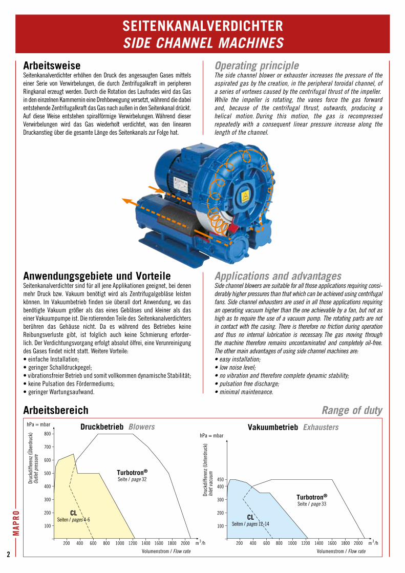
ArbeitsweiseSeitenkanalverdichter erhöhen den Druck des angesaugten Gases mittels einer Serie von Verwirbelungen, die durch Zentrifugalkraft im peripheren Ringkanal erzeugt werden. Durch die Rotation des Laufrades wird das Gas in den einzelnen Kammernin eine Drehbewegung versetzt, während die dabei entstehende Zentrifugalkraft das Gas nach außen in den Seitenkanal drückt. Auf diese Weise entstehen spiralförmige Verwirbelungen. Während dieser Verwirbelungen wird das Gas wiederholt verdichtet, was den linearen Druckanstieg über die gesamte Länge des Seitenkanals zur Folge hat.
Anwendungsgebiete und VorteileSeitenkanalverdichter sind für all jene Applikationen geeignet, bei denen mehr Druck bzw. Vakuum benötigt wird als Zentrifugalgebläse leisten können. Im Vakuumbetrieb finden sie überall dort Anwendung, wo das benötigte Vakuum größer als das eines Gebläses und kleiner als das einer Vakuumpumpe ist. Die rotierenden Teile des Seitenkanalverdichters berühren das Gehäuse nicht. Da es während des Betriebes keine Reibungsverluste gibt, ist folglich auch keine Schmierung erforder-lich. Der Verdichtungsvorgang erfolgt absolut ölfrei, eine Verunreinigung des Gases findet nicht statt. Weitere Vorteile:• einfache Installation;• geringer Schalldruckpegel;• vibrationsfreier Betrieb und somit vollkommen dynamische Stabilität;• keine Pulsation des Fördermediums;• geringer Wartungsaufwand.
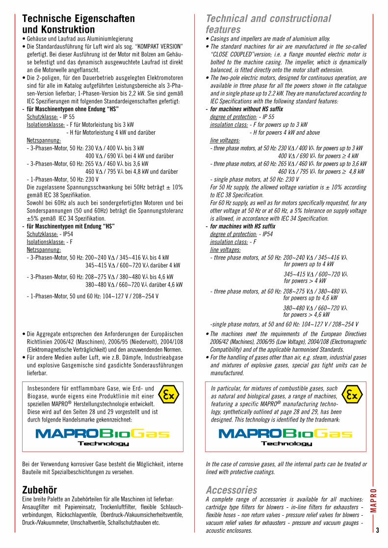
Arbeitsbereich Range of duty
SEITENKANALVERDICHTERSIDE CHANNEL MACHINES
Operating principleThe side channel blower or exhauster increases the pressure of the aspirated gas by the creation, in the peripheral toroidal channel, of a series of vortexes caused by the centrifugal thrust of the impeller.While the impeller is rotating, the vanes force the gas forward and, because of the centrifugal thrust, outwards, producing a helical motion. During this motion, the gas is recompressed repeatedly with a consequent linear pressure increase along the length of the channel.
Applications and advantagesSide channel blowers are suitable for all those applications requiring consi-derably higher pressures than that which can be achieved using centrifugal fans. Side channel exhausters are used in all those applications requiring an operating vacuum higher than the one achievable by a fan, but not as high as to require the use of a vacuum pump. The rotating parts are not in contact with the casing. There is therefore no friction during operation and thus no internal lubrication is necessary. The gas moving through the machine therefore remains uncontaminated and completely oil-free. The other main advantages of using side channel machines are:• easy installation;• low noise level;• no vibration and therefore complete dynamic stability;• pulsation free discharge; • minimal maintenance.
800
700
600
500
400
300
200
100
200 400 600 800 200018001600140012001000 m 3 /h
hPa = mbar
hPa = mbar
450400
300
200
100
200 400 600 800 200018001600140012001000 m 3 /h
Volumenstrom / Flow rate Volumenstrom / Flow rate
Druc
kdiff
eren
z (Üb
erdr
uck)
Ou
tlet p
ress
ure
Druc
kdiff
eren
z (Un
terd
ruck
) In
let v
acuu
m
CLSeiten / pages 4-6 CL
Seiten / pages 12-14
Turbotron®
Seite / page 32
Turbotron®
Seite / page 33
Druckbetrieb Blowers Vakuumbetrieb Exhausters
MAP
RO
3
Technische Eigenschaften und Konstruktion• Gehäuse und Laufrad aus Aluminiumlegierung• Die Standardausführung für Luft wird als sog. “KOMPAKT VERSION”
gefertigt. Bei dieser Ausführung ist der Motor mit Bolzen am Gehäu-se befestigt und das dynamisch ausgewuchtete Laufrad ist direkt an die Motorwelle angeflanscht.
• Die 2-poligen, für den Dauerbetrieb ausgelegten Elektromotoren sind für alle im Katalog aufgeführten Leistungsbereiche als 3-Pha-sen-Version lieferbar; 1-Phasen-Version bis 2,2 kW. Sie sind gemäß IEC Spezifierungen mit folgenden Standardeigenschaften gefertigt:
- für Maschinentypen ohne Endung “HS”Schutzklasse: - IP 55Isolationsklasse: - F für Motorleistung bis 3 kW
- H für Motorleistung 4 kW und darüberNetzspannung:- 3-Phasen-Motor, 50 Hz: 230 V∆ / 400 V bis 3 kW
400 V∆ / 690 V bei 4 kW und darüber- 3-Phasen-Motor, 60 Hz: 265 V∆ / 460 V bis 3,6 kW
460 V∆ / 795 V bei 4,8 kW und darüber- 1-Phasen-Motor, 50 Hz: 230 VDie zugelassene Spannungsschwankung bei 50Hz beträgt ± 10% gemäß IEC 38 Spezifikation.Sowohl bei 60Hz als auch bei sondergefertigten Motoren und bei Sonderspannungen (50 und 60Hz) beträgt die Spannungstoleranz ±5% gemäß IEC 34 Spezifikation.
- für Maschinentypen mit Endung “HS”Schutzklasse: - IP54Isolationsklasse: - FNetzspannung:- 3-Phasen-Motor, 50 Hz: 200~240 V∆ / 345~416 V bis 4 kW
345~415 V∆ / 600~720 V darüber 4 kW
- 3-Phasen-Motor, 60 Hz: 208~275 V∆ / 380~480 V bis 4,6 kW 380~480 V∆ / 660~720 V darüber 4,6 kW
- 1-Phasen-Motor, 50 und 60 Hz: 104~127 V / 208~254 V
ZubehörEine breite Palette an Zubehörteilen für alle Maschinen ist lieferbar:Ansaugfilter mit Papiereinsatz, Trockenluftfilter, flexible Schlauch- verbindungen, Rückschlagventile, Überdruck-/Vakuumsicherheitsventile, Druck-/Vakuummeter, Umschaltventile, Schallschutzhauben etc.
Bei der Verwendung korrosiver Gase besteht die Möglichkeit, interne Bauteile mit Spezialbeschichtungen zu versehen.
In the case of corrosive gases, all the internal parts can be treated or lined with protective coatings.
AccessoriesA complete range of accessories is available for all machines:cartridge type filters for blowers - in-line filters for exhausters - flexible hoses - non return valves - pressure relief valves for blowers -vacuum relief valves for exhausters - pressure and vacuum gauges - acoustic enclosures.
Technical and constructional features• Casings and impellers are made of aluminium alloy.• The standard machines for air are manufactured in the so-called
“CLOSE COUPLED”version; i.e. a flange mounted electric motor is bolted to the machine casing. The impeller, which is dynamically balanced, is fitted directly onto the motor shaft extension.
• The two-pole electric motors, designed for continuous operation, are available in three phase for all the powers shown in the catalogue and in single phase up to 2.2 kW. They are manufactured according to IEC Specifications with the following standard features:
- for machines without HS suffixdegree of protection: - IP 55insulation class: - F for powers up to 3 kW
- H for powers 4 kW and aboveline voltages:- three phase motors, at 50 Hz: 230 V∆ / 400 V for powers up to 3 kW
400 V∆ / 690 V for powers ≥ 4 kW- three phase motors, at 60 Hz: 265 V∆ / 460 V for powers up to 3,6 kW
460 V∆ / 795 V for powers ≥ 4,8 kW - single phase motors, at 50 Hz: 230 VFor 50 Hz supply, the allowed voltage variation is ± 10% according to IEC 38 Specification.For 60 Hz supply, as well as for motors specifically requested, for any other voltage at 50 Hz or at 60 Hz, a 5% tolerance on supply voltage is allowed, in accordance with IEC 34 Specification.
- for machines with HS suffixdegree of protection: - IP54insulation class: - Fline voltages:- three phase motors, at 50 Hz: 200~240 V∆ / 345~416 V for powers up to 4 kW
345~415 V∆ / 600~720 V for powers > 4 kW
- three phase motors, at 60 Hz: 208~275 V∆ / 380~480 V for powers up to 4,6 kW
380~480 V∆ / 660~720 V for powers > 4,6 kW
-single phase motors, at 50 and 60 Hz: 104~127 V / 208~254 V
• The machines meet the requirements of the European Directives 2006/42 (Machines), 2006/95 (Low Voltage), 2004/108 (Electromagnetic Compatibility) and of the applicable harmonised Standards.
• For the handling of gases other than air, e.g. steam, industrial gases and mixtures of explosive gases, special gas tight units can be manufactured.
Insbesondere für entflammbare Gase, wie Erd- und Biogase, wurde eigens eine Produktlinie mit einer speziellen MAPRO® Herstellungstechnologie entwickelt. Diese wird auf den Seiten 28 und 29 vorgestellt und ist durch folgende Handelsmarke gekennzeichnet:
In particular, for mixtures of combustible gases, such as natural and biological gases, a range of machines, featuring a specific MAPRO® manufacturing techno-logy, synthetically outlined at page 28 and 29, has been designed. This technology is identified by the trademark:
• Die Aggregate entsprechen den Anforderungen der Europäischen Richtlinien 2006/42 (Maschinen), 2006/95 (Niedervolt), 2004/108 (Elektromagnetische Verträglichkeit) und den anzuwendenden Normen.
• Für andere Medien außer Luft, wie z.B. Dämpfe, Industrieabgase und explosive Gasgemische sind gasdichte Sonderausführungen lieferbar.
4
MAP
RO
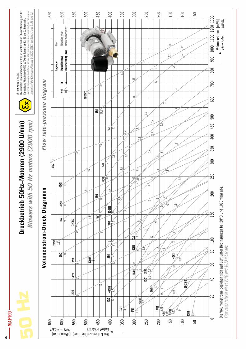
Druc
kbet
rieb
50H
z–M
otor
en (
2900
U/m
in)
Blow
ers
with
50
Hz
mot
ors
(290
0 rp
m)
50 H
z 2060
100
200
300
400
500
600
700
800
900
4080
150
250
350
450
1000
1200
1100
1300
50100
150
200
250
300
350
400
450
500
550
600
650
0
50100
150
200
250
300
350
400
450
500
550
600
650
Druckdifferenz (Überdruck) [hPa = mbar]Outlet pressure [hPa = mbar]
Volu
men
stro
m [
m3 /h
]Fl
ow ra
te
[m3 /h
]
1115
18,5
4
5,5
7,5
9,2
11
11
15
5,5
7,5
9,2
18,5
22
25
15
11
9,2
9,2
11
0,91,1
1,1
1,1
0,75
1,5
0,40,75
0,55
0,75
0,8
1,5
1,1 1,10,5
5
0,22
2,2
3
2,231,5
1,54
2,234
1,5
7,5
1,1
4
5,5
5,57,5
5,5
4,3
3
2,22,2
2,2
34
3
7,53
3
4
5,52,2
4
4
9,2
5,5
7,5
7,59,2
7,5
0,37 0,2
51,5
3
3
4
4
7,5
9,2
7,5
5,5
11
2,2
3
7,5
157,5
2,22,2
11
45,5
5,55,5 2,23
4
5,57,5
9,2
3
3
44
5,55,5
15
4
1,6
4/01
60/1
7/21
17/21
84/1
10/21
420H
S
22/01
98/1
4/21
220H
S
40HS
50HS
20HS3,6
/01
10/01
15/01
18/01
60HS
7/01
12/21
34/1
80-ZH
S
14/21
28/1
520H
S
46/1
72/1
20/21
23/21
720H
S30/21
36/21
49/21
40/1
42/21
TBT/M
®
30-Z
HS
Vol
umen
stro
m-D
ruck
Dia
gram
m
Flo
w r
ate-
pres
sure
dia
gram
Lege
nde
Key
Masc
hine
ntyp
Ma
chin
e ty
peMo
torle
istun
g (k
W)
Moto
r pow
er (k
W)
60/1
11Anm
erku
ng /
Note
:Di
e m
einst
en S
eiten
kana
lverd
ichte
r für
Luf
t wur
den
auch
in Ü
bere
inst
imm
ung
mit
der
Euro
päisc
he R
ichtli
nie 9
4/9/
EG (A
TEX)
für Z
onen
1 u
nd 2
, 21
und
22 h
erge
stell
t.M
ost o
f the
blo
wer m
odel
s fo
r air
are
also
man
ufac
ture
d in
con
form
ity to
the
requ
i-re
men
ts o
f the
Eur
opea
n Di
rect
ive
94/9
/EC
(ATE
X) fo
r Zon
es 1
and
2, 2
1 an
d 22
.
Die
Volu
men
strö
me
bezie
hen
sich
auf
Luf
t unt
er B
edin
gung
en b
ei 2
0°C
und
1013
mba
r abs
.Fl
ow ra
tes
refe
r to
air a
t 20°
C an
d 10
13 m
bar a
bs.
5
MAP
RO
MAP
RO
7 8
Druckdifferenz (Überdruck)Outlet pressure
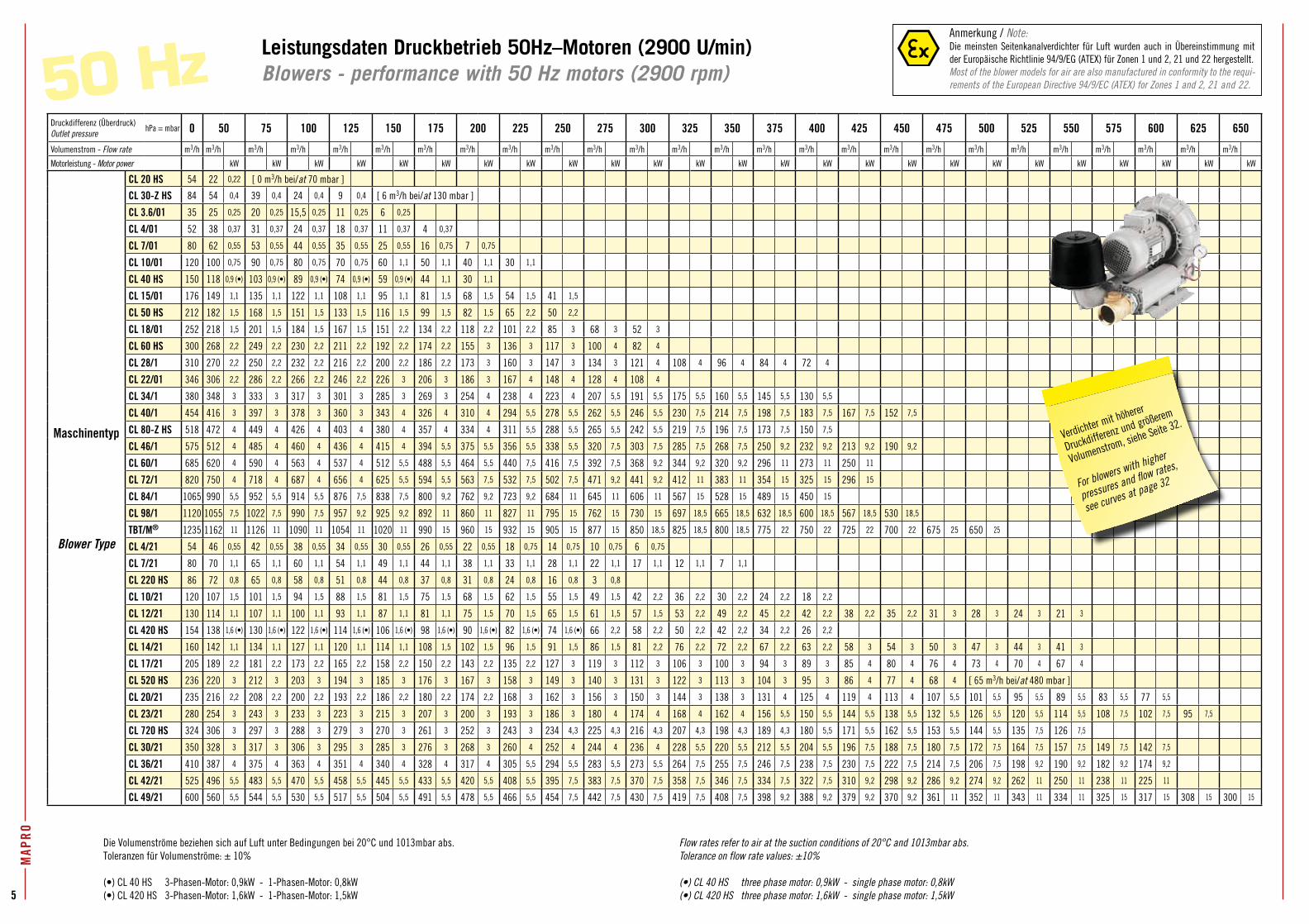
hPa = mbar 0 50 75 100 125 150 175 200 225 250 275 300 325 350 375 400 425 450 475 500 525 550 575 600 625 650
Volumenstrom - Flow rate m3/h m3/h m3/h m3/h m3/h m3/h m3/h m3/h m3/h m3/h m3/h m3/h m3/h m3/h m3/h m3/h m3/h m3/h m3/h m3/h m3/h m3/h m3/h m3/h m3/h m3/h
Motorleistung - Motor power kW kW kW kW kW kW kW kW kW kW kW kW kW kW kW kW kW kW kW kW kW kW kW kW kW
Maschinentyp
Blower Type
CL 20 HS 54 22 0,22 [ 0 m3/h bei/at 70 mbar ]
CL 30-Z HS 84 54 0,4 39 0,4 24 0,4 9 0,4 [ 6 m3/h bei/at 130 mbar ]
CL 3.6/01 35 25 0,25 20 0,25 15,5 0,25 11 0,25 6 0,25
CL 4/01 52 38 0,37 31 0,37 24 0,37 18 0,37 11 0,37 4 0,37
CL 7/01 80 62 0,55 53 0,55 44 0,55 35 0,55 25 0,55 16 0,75 7 0,75
CL 10/01 120 100 0,75 90 0,75 80 0,75 70 0,75 60 1,1 50 1,1 40 1,1 30 1,1
CL 40 HS 150 118 0,9 (•) 103 0,9 (•) 89 0,9 (•) 74 0,9 (•) 59 0,9 (•) 44 1,1 30 1,1
CL 15/01 176 149 1,1 135 1,1 122 1,1 108 1,1 95 1,1 81 1,5 68 1,5 54 1,5 41 1,5
CL 50 HS 212 182 1,5 168 1,5 151 1,5 133 1,5 116 1,5 99 1,5 82 1,5 65 2,2 50 2,2
CL 18/01 252 218 1,5 201 1,5 184 1,5 167 1,5 151 2,2 134 2,2 118 2,2 101 2,2 85 3 68 3 52 3
CL 60 HS 300 268 2,2 249 2,2 230 2,2 211 2,2 192 2,2 174 2,2 155 3 136 3 117 3 100 4 82 4
CL 28/1 310 270 2,2 250 2,2 232 2,2 216 2,2 200 2,2 186 2,2 173 3 160 3 147 3 134 3 121 4 108 4 96 4 84 4 72 4
CL 22/01 346 306 2,2 286 2,2 266 2,2 246 2,2 226 3 206 3 186 3 167 4 148 4 128 4 108 4
CL 34/1 380 348 3 333 3 317 3 301 3 285 3 269 3 254 4 238 4 223 4 207 5,5 191 5,5 175 5,5 160 5,5 145 5,5 130 5,5
CL 40/1 454 416 3 397 3 378 3 360 3 343 4 326 4 310 4 294 5,5 278 5,5 262 5,5 246 5,5 230 7,5 214 7,5 198 7,5 183 7,5 167 7,5 152 7,5
CL 80-Z HS 518 472 4 449 4 426 4 403 4 380 4 357 4 334 4 311 5,5 288 5,5 265 5,5 242 5,5 219 7,5 196 7,5 173 7,5 150 7,5
CL 46/1 575 512 4 485 4 460 4 436 4 415 4 394 5,5 375 5,5 356 5,5 338 5,5 320 7,5 303 7,5 285 7,5 268 7,5 250 9,2 232 9,2 213 9,2 190 9,2
CL 60/1 685 620 4 590 4 563 4 537 4 512 5,5 488 5,5 464 5,5 440 7,5 416 7,5 392 7,5 368 9,2 344 9,2 320 9,2 296 11 273 11 250 11
CL 72/1 820 750 4 718 4 687 4 656 4 625 5,5 594 5,5 563 7,5 532 7,5 502 7,5 471 9,2 441 9,2 412 11 383 11 354 15 325 15 296 15
CL 84/1 1065 990 5,5 952 5,5 914 5,5 876 7,5 838 7,5 800 9,2 762 9,2 723 9,2 684 11 645 11 606 11 567 15 528 15 489 15 450 15
CL 98/1 1120 1055 7,5 1022 7,5 990 7,5 957 9,2 925 9,2 892 11 860 11 827 11 795 15 762 15 730 15 697 18,5 665 18,5 632 18,5 600 18,5 567 18,5 530 18,5
TBT/M® 1235 1162 11 1126 11 1090 11 1054 11 1020 11 990 15 960 15 932 15 905 15 877 15 850 18,5 825 18,5 800 18,5 775 22 750 22 725 22 700 22 675 25 650 25
CL 4/21 54 46 0,55 42 0,55 38 0,55 34 0,55 30 0,55 26 0,55 22 0,55 18 0,75 14 0,75 10 0,75 6 0,75
CL 7/21 80 70 1,1 65 1,1 60 1,1 54 1,1 49 1,1 44 1,1 38 1,1 33 1,1 28 1,1 22 1,1 17 1,1 12 1,1 7 1,1
CL 220 HS 86 72 0,8 65 0,8 58 0,8 51 0,8 44 0,8 37 0,8 31 0,8 24 0,8 16 0,8 3 0,8
CL 10/21 120 107 1,5 101 1,5 94 1,5 88 1,5 81 1,5 75 1,5 68 1,5 62 1,5 55 1,5 49 1,5 42 2,2 36 2,2 30 2,2 24 2,2 18 2,2
CL 12/21 130 114 1,1 107 1,1 100 1,1 93 1,1 87 1,1 81 1,1 75 1,5 70 1,5 65 1,5 61 1,5 57 1,5 53 2,2 49 2,2 45 2,2 42 2,2 38 2,2 35 2,2 31 3 28 3 24 3 21 3
CL 420 HS 154 138 1,6 (•) 130 1,6 (•) 122 1,6 (•) 114 1,6 (•) 106 1,6 (•) 98 1,6 (•) 90 1,6 (•) 82 1,6 (•) 74 1,6 (•) 66 2,2 58 2,2 50 2,2 42 2,2 34 2,2 26 2,2
CL 14/21 160 142 1,1 134 1,1 127 1,1 120 1,1 114 1,1 108 1,5 102 1,5 96 1,5 91 1,5 86 1,5 81 2,2 76 2,2 72 2,2 67 2,2 63 2,2 58 3 54 3 50 3 47 3 44 3 41 3
CL 17/21 205 189 2,2 181 2,2 173 2,2 165 2,2 158 2,2 150 2,2 143 2,2 135 2,2 127 3 119 3 112 3 106 3 100 3 94 3 89 3 85 4 80 4 76 4 73 4 70 4 67 4
CL 520 HS 236 220 3 212 3 203 3 194 3 185 3 176 3 167 3 158 3 149 3 140 3 131 3 122 3 113 3 104 3 95 3 86 4 77 4 68 4 [ 65 m3/h bei/at 480 mbar ]
CL 20/21 235 216 2,2 208 2,2 200 2,2 193 2,2 186 2,2 180 2,2 174 2,2 168 3 162 3 156 3 150 3 144 3 138 3 131 4 125 4 119 4 113 4 107 5,5 101 5,5 95 5,5 89 5,5 83 5,5 77 5,5
CL 23/21 280 254 3 243 3 233 3 223 3 215 3 207 3 200 3 193 3 186 3 180 4 174 4 168 4 162 4 156 5,5 150 5,5 144 5,5 138 5,5 132 5,5 126 5,5 120 5,5 114 5,5 108 7,5 102 7,5 95 7,5
CL 720 HS 324 306 3 297 3 288 3 279 3 270 3 261 3 252 3 243 3 234 4,3 225 4,3 216 4,3 207 4,3 198 4,3 189 4,3 180 5,5 171 5,5 162 5,5 153 5,5 144 5,5 135 7,5 126 7,5
CL 30/21 350 328 3 317 3 306 3 295 3 285 3 276 3 268 3 260 4 252 4 244 4 236 4 228 5,5 220 5,5 212 5,5 204 5,5 196 7,5 188 7,5 180 7,5 172 7,5 164 7,5 157 7,5 149 7,5 142 7,5
CL 36/21 410 387 4 375 4 363 4 351 4 340 4 328 4 317 4 305 5,5 294 5,5 283 5,5 273 5,5 264 7,5 255 7,5 246 7,5 238 7,5 230 7,5 222 7,5 214 7,5 206 7,5 198 9,2 190 9,2 182 9,2 174 9,2
CL 42/21 525 496 5,5 483 5,5 470 5,5 458 5,5 445 5,5 433 5,5 420 5,5 408 5,5 395 7,5 383 7,5 370 7,5 358 7,5 346 7,5 334 7,5 322 7,5 310 9,2 298 9,2 286 9,2 274 9,2 262 11 250 11 238 11 225 11
CL 49/21 600 560 5,5 544 5,5 530 5,5 517 5,5 504 5,5 491 5,5 478 5,5 466 5,5 454 7,5 442 7,5 430 7,5 419 7,5 408 7,5 398 9,2 388 9,2 379 9,2 370 9,2 361 11 352 11 343 11 334 11 325 15 317 15 308 15 300 15
Die Volumenströme beziehen sich auf Luft unter Bedingungen bei 20°C und 1013mbar abs.Toleranzen für Volumenströme: ± 10%
(•) CL 40 HS 3-Phasen-Motor: 0,9kW - 1-Phasen-Motor: 0,8kW(•) CL 420 HS 3-Phasen-Motor: 1,6kW - 1-Phasen-Motor: 1,5kW
Flow rates refer to air at the suction conditions of 20°C and 1013mbar abs.Tolerance on flow rate values: ±10%
(•) CL 40 HS three phase motor: 0,9kW - single phase motor: 0,8kW(•) CL 420 HS three phase motor: 1,6kW - single phase motor: 1,5kW
Leistungsdaten Druckbetrieb 50Hz–Motoren (2900 U/min)Blowers - performance with 50 Hz motors (2900 rpm)50 Hz
Anmerkung / Note:Die meinsten Seitenkanalverdichter für Luft wurden auch in Übereinstimmung mit der Europäische Richtlinie 94/9/EG (ATEX) für Zonen 1 und 2, 21 und 22 hergestellt.Most of the blower models for air are also manufactured in conformity to the requi-rements of the European Directive 94/9/EC (ATEX) for Zones 1 and 2, 21 and 22.
MAP
RO
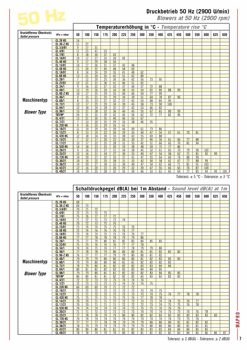
Druckbetrieb 50 Hz (2900 U/min)Blowers at 50 Hz (2900 rpm)50 Hz
Toleranz: ± 5 °C - Tolerance: ± 5 °C
Toleranz: ± 2 dB(A) - Tolerance: ± 2 dB(A)
Verdichter mit höherer
Druckdifferenz und größerem
Volumenstrom, siehe Seite 32.
For blowers with higher
pressures and flow rates,
see curves at page 32
Temperaturerhöhung in °C - Temperature rise °CDruckdifferenz (Überdruck)Outlet pressure
hPa = mbar 50 100 150 175 200 225 250 300 350 400 425 450 500 550 600 625 650
Maschinentyp
Blower Type
CL 20 HS 14CL 30-Z HS 11 27CL 3.6/01 9 17 31CL 4/01 11 23 41 53CL 7/01 8 18 30 37 43CL 10/01 10 17 27 33 39 45CL 40 HS 9 17 29 38 54CL 15/01 10 17 26 31 37 42 48CL 50 HS 11 20 32 40 48 58 69CL 18/01 8 14 24 29 35 41 48 62CL 60 HS 13 21 30 35 42 51 62 89CL 28/1 7 12 20 25 30 36 42 56 73 95CL 22/01 12 21 31 36 41 46 51 62CL 34/1 9 16 22 27 32 37 44 57 72 88CL 40/1 13 19 26 30 34 38 43 54 65 80 88 99CL 80-Z HS 10 17 25 29 35 40 46 59 77 99CL 46/1 9 15 21 25 29 34 39 51 64 78 87 96CL 60/1 8 15 23 27 32 37 42 53 68 85 95CL 72/1 12 17 25 29 34 39 45 58 73 90 100CL 84/1 12 18 24 28 32 37 42 53 66 82CL 98/1 15 21 28 32 36 40 45 55 67 81 89 99TBT/M® 24 31 35 39 42 46 54 62 72 77 82 96CL 4/21 13 21 30 35 40 46 52 67CL 7/21 7 13 20 25 29 33 38 46 55CL 220 HS 9 16 25 29 35 41CL 10/21 11 19 29 34 39 44 49 61 73 86CL 12/21 8 13 19 22 26 29 33 40 47 54 57 61 70 81CL 420 HS 12 18 24 30 33 38 43 55 69 88CL 14/21 7 12 17 20 23 26 30 37 46 56 61 66 77 88CL 17/21 13 17 22 25 28 31 35 42 51 60 65 70 81 94CL 520 HS 14 18 23 25 30 33 38 48 59 72 77 86CL 20/21 9 16 23 27 31 34 38 45 52 61 65 70 79 90 102CL 23/21 12 16 21 24 27 30 33 40 47 54 58 62 71 81 92 99CL 720 HS 14 20 27 32 35 37 41 47 55 64 69 74 86 99CL 30/21 10 16 22 25 28 31 35 42 50 58 62 67 77 88 99CL 36/21 14 20 27 30 33 36 40 47 54 62 66 71 81 91 103CL 42/21 12 16 20 23 26 29 32 39 47 55 60 65 76 87 100CL 49/21 14 19 25 28 32 35 39 46 53 61 65 69 77 85 94 99 105
Schalldruckpegel dB(A) bei 1m Abstand - Sound level dB(A) at 1mDruckdifferenz (Überdruck)Outlet pressure
hPa = mbar 50 100 150 175 200 225 250 300 350 400 425 450 500 550 600 625 650
Maschinentyp
Blower Type
CL 20 HS 68CL 30-Z HS 69 73CL 3.6/01 70 71 72CL 4/01 72 73 75 75CL 7/01 75 76 77 77 77CL 10/01 71 72 72 73 73 74CL 40 HS 70 72 73 75 76CL 15/01 73 74 74 75 75 76 76CL 50 HS 72 74 76 76 76 76 77CL 18/01 73 74 74 75 75 76 76 77CL 60 HS 77 77 78 78 78 79 79 80CL 28/1 75 77 79 80 81 82 83 84 85 85CL 22/01 75 75 76 76 76 77 77 78CL 34/1 74 74 75 76 77 77 78 79 79 80CL 40/1 77 78 78 79 80 80 80 81 81 82 82 83CL 80-Z HS 76 77 77 77 79 79 80 80 81 82CL 46/1 79 79 79 80 80 80 80 81 82 83 83 83CL 60/1 79 79 80 80 80 81 81 82 82 82 82CL 72/1 78 79 80 81 82 82 82 83 83 84 84CL 84/1 80 81 82 82 83 83 83 84 84 85CL 98/1 79 79 80 81 81 82 82 82 83 84 85 85TBT/M® 80 80 81 81 82 82 82 83 83 83 83 83CL 4/21 72 72 73 73 73 74 74 74CL 7/21 72 73 73 73 73 74 74 74 75CL 220 HS 66 69 69 70 71 72 72CL 10/21 72 72 72 72 72 73 73 73 74 75CL 12/21 71 71 72 72 73 73 73 73 74 75 76 77 78 78CL 420 HS 75 75 75 75 75 75 76 77 78 78CL 14/21 70 70 71 71 72 72 73 73 73 74 74 75 76 77CL 17/21 70 70 71 71 71 72 72 72 73 74 75 75 76 78CL 520 HS 74 74 74 74 74 74 75 75 75 76 76 76CL 20/21 71 71 72 72 73 73 73 74 74 74 75 75 75 76 78CL 23/21 77 78 78 79 79 80 80 82 82 83 83 83 83 83 83 83CL 720 HS 74 74 74 74 74 74 74 74 74 74 74 75 75 76CL 30/21 77 77 77 78 78 79 79 79 80 80 80 81 81 82 82CL 36/21 78 79 79 79 79 79 79 79 80 80 80 80 81 81 81CL 42/21 80 80 80 81 81 81 82 83 83 83 84 84 84 85 85CL 49/21 78 78 79 79 79 80 80 81 81 82 82 83 84 85 86 86 87 6
0 H
z
1,3
9
8,6
6,3
18
0,30,5
0,440,9
3,64,6
0,90,9
1,8
3,6
4,8
4,6
0,28
2,65
3,6
4,82,6
52,5
5
3,6
2,65
0,66
0,9
1,3
1,8
0,9
1,3
2,2
1,75
2,05
2,55
2,653,4
54,8
6,6
9
0,66
1,32,6
5
3,6
4,8 3,45
4,8
1,8
3,6
1,8
1,3
1,8
2,55
3,63,6
3,45
4,8
4,8
6,64,8
9
8,6
9
11
13,2
2,65
6,6
6,6
3,6
3,6
4,8
6,6
9
1111
9
6,66,3
4,8
13,2
18
2,65
3,6
4,8
6,6
6,6
9
11
6,6
9
11
13,2
18
9
11
13,2
18
22
13,2
18
22
26
30
6,6
9
11
13,2
9
11
13,2
18
6,6
9
11
4,8
4,8
3,6/01
30-Z
HS
4/017/0
1
10/01
40HS
15/01
50HS
18/01
60HS
22/0134
/1
40/1
46/1
80-Z
HS60
/1
72/1
98/1
TBT/M
®
4/21
220H
S7/21
17/21
20/21
23/21
720H
S30
/2136
/21
49/21
20HS
84/1
42/21
14/21
28/1
10/21
12/21
520H
S
420H
S
50100
150
200
250
300
350
400
450
500
550
600
650
2060
100
200
300
400
500
550
600
700
650
750
800
900
4080
150
250
350
450
1000
1200
1100
1300
1400
1500
0
50100
150
200
250
300
350
400
450
500
550
600
650
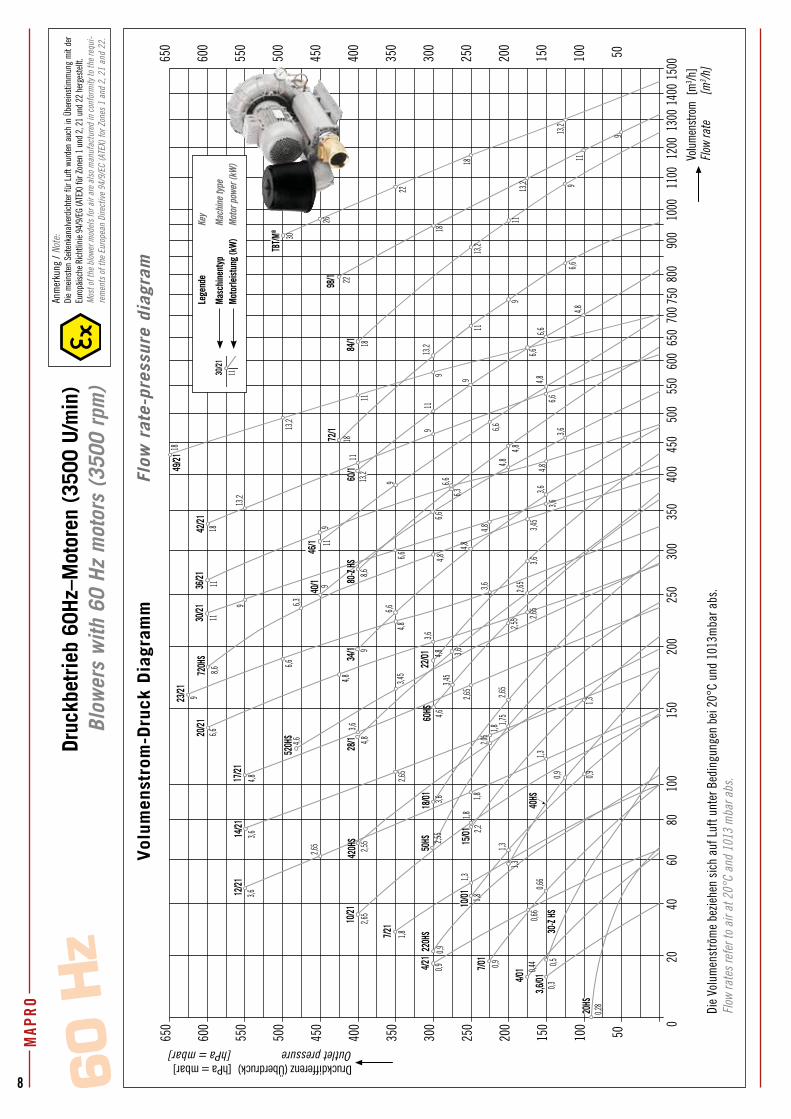
Druckdifferenz (Überdruck) [hPa = mbar]Outlet pressure [hPa = mbar]
Volu
men
stro
m [
m3 /h
]Fl
ow ra
te
[m3 /h
]
Vol
umen
stro
m-D
ruck
Dia
gram
m
Flo
w r
ate-
pres
sure
dia
gram
30/21
11
Druc
kbet
rieb
60H
z–M
otor
en (
3500
U/m
in)
Blow
ers
with
60
Hz
mot
ors
(350
0 rp
m)
Anm
erku
ng /
Note
:Di
e m
einst
en S
eiten
kana
lverd
ichte
r für
Luf
t wur
den
auch
in Ü
bere
inst
imm
ung
mit
der
Euro
päisc
he R
ichtli
nie 9
4/9/
EG (A
TEX)
für Z
onen
1 u
nd 2
, 21
und
22 h
erge
stell
t.M
ost o
f the
blo
wer m
odel
s fo
r air
are
also
man
ufac
ture
d in
con
form
ity to
the
requ
i-re
men
ts o
f the
Eur
opea
n Di
rect
ive
94/9
/EC
(ATE
X) fo
r Zon
es 1
and
2, 2
1 an
d 22
.
Die
Volu
men
strö
me
bezie
hen
sich
auf
Luf
t unt
er B
edin
gung
en b
ei 2
0°C
und
1013
mba
r abs
.Fl
ow ra
tes
refe
r to
air a
t 20°
C an
d 10
13 m
bar a
bs.
Lege
nde
Key
Masc
hine
ntyp
Ma
chin
e ty
peMo
torle
istun
g (k
W)
Moto
r pow
er (k
W)
7
MAP
RO
Druckbetrieb 50 Hz (2900 U/min)Blowers at 50 Hz (2900 rpm)50 Hz
Toleranz: ± 5 °C - Tolerance: ± 5 °C
Toleranz: ± 2 dB(A) - Tolerance: ± 2 dB(A)
Temperaturerhöhung in °C - Temperature rise °CDruckdifferenz (Überdruck)Outlet pressure
hPa = mbar 50 100 150 175 200 225 250 300 350 400 425 450 500 550 600 625 650
Maschinentyp
Blower Type
CL 20 HS 14CL 30-Z HS 11 27CL 3.6/01 9 17 31CL 4/01 11 23 41 53CL 7/01 8 18 30 37 43CL 10/01 10 17 27 33 39 45CL 40 HS 9 17 29 38 54CL 15/01 10 17 26 31 37 42 48CL 50 HS 11 20 32 40 48 58 69CL 18/01 8 14 24 29 35 41 48 62CL 60 HS 13 21 30 35 42 51 62 89CL 28/1 7 12 20 25 30 36 42 56 73 95CL 22/01 12 21 31 36 41 46 51 62CL 34/1 9 16 22 27 32 37 44 57 72 88CL 40/1 13 19 26 30 34 38 43 54 65 80 88 99CL 80-Z HS 10 17 25 29 35 40 46 59 77 99CL 46/1 9 15 21 25 29 34 39 51 64 78 87 96CL 60/1 8 15 23 27 32 37 42 53 68 85 95CL 72/1 12 17 25 29 34 39 45 58 73 90 100CL 84/1 12 18 24 28 32 37 42 53 66 82CL 98/1 15 21 28 32 36 40 45 55 67 81 89 99TBT/M® 24 31 35 39 42 46 54 62 72 77 82 96CL 4/21 13 21 30 35 40 46 52 67CL 7/21 7 13 20 25 29 33 38 46 55CL 220 HS 9 16 25 29 35 41CL 10/21 11 19 29 34 39 44 49 61 73 86CL 12/21 8 13 19 22 26 29 33 40 47 54 57 61 70 81CL 420 HS 12 18 24 30 33 38 43 55 69 88CL 14/21 7 12 17 20 23 26 30 37 46 56 61 66 77 88CL 17/21 13 17 22 25 28 31 35 42 51 60 65 70 81 94CL 520 HS 14 18 23 25 30 33 38 48 59 72 77 86CL 20/21 9 16 23 27 31 34 38 45 52 61 65 70 79 90 102CL 23/21 12 16 21 24 27 30 33 40 47 54 58 62 71 81 92 99CL 720 HS 14 20 27 32 35 37 41 47 55 64 69 74 86 99CL 30/21 10 16 22 25 28 31 35 42 50 58 62 67 77 88 99CL 36/21 14 20 27 30 33 36 40 47 54 62 66 71 81 91 103CL 42/21 12 16 20 23 26 29 32 39 47 55 60 65 76 87 100CL 49/21 14 19 25 28 32 35 39 46 53 61 65 69 77 85 94 99 105
Schalldruckpegel dB(A) bei 1m Abstand - Sound level dB(A) at 1mDruckdifferenz (Überdruck)Outlet pressure
hPa = mbar 50 100 150 175 200 225 250 300 350 400 425 450 500 550 600 625 650
Maschinentyp
Blower Type
CL 20 HS 68CL 30-Z HS 69 73CL 3.6/01 70 71 72CL 4/01 72 73 75 75CL 7/01 75 76 77 77 77CL 10/01 71 72 72 73 73 74CL 40 HS 70 72 73 75 76CL 15/01 73 74 74 75 75 76 76CL 50 HS 72 74 76 76 76 76 77CL 18/01 73 74 74 75 75 76 76 77CL 60 HS 77 77 78 78 78 79 79 80CL 28/1 75 77 79 80 81 82 83 84 85 85CL 22/01 75 75 76 76 76 77 77 78CL 34/1 74 74 75 76 77 77 78 79 79 80CL 40/1 77 78 78 79 80 80 80 81 81 82 82 83CL 80-Z HS 76 77 77 77 79 79 80 80 81 82CL 46/1 79 79 79 80 80 80 80 81 82 83 83 83CL 60/1 79 79 80 80 80 81 81 82 82 82 82CL 72/1 78 79 80 81 82 82 82 83 83 84 84CL 84/1 80 81 82 82 83 83 83 84 84 85CL 98/1 79 79 80 81 81 82 82 82 83 84 85 85TBT/M® 80 80 81 81 82 82 82 83 83 83 83 83CL 4/21 72 72 73 73 73 74 74 74CL 7/21 72 73 73 73 73 74 74 74 75CL 220 HS 66 69 69 70 71 72 72CL 10/21 72 72 72 72 72 73 73 73 74 75CL 12/21 71 71 72 72 73 73 73 73 74 75 76 77 78 78CL 420 HS 75 75 75 75 75 75 76 77 78 78CL 14/21 70 70 71 71 72 72 73 73 73 74 74 75 76 77CL 17/21 70 70 71 71 71 72 72 72 73 74 75 75 76 78CL 520 HS 74 74 74 74 74 74 75 75 75 76 76 76CL 20/21 71 71 72 72 73 73 73 74 74 74 75 75 75 76 78CL 23/21 77 78 78 79 79 80 80 82 82 83 83 83 83 83 83 83CL 720 HS 74 74 74 74 74 74 74 74 74 74 74 75 75 76CL 30/21 77 77 77 78 78 79 79 79 80 80 80 81 81 82 82CL 36/21 78 79 79 79 79 79 79 79 80 80 80 80 81 81 81CL 42/21 80 80 80 81 81 81 82 83 83 83 84 84 84 85 85CL 49/21 78 78 79 79 79 80 80 81 81 82 82 83 84 85 86 86 87
MAP
RO
8 60 H
z
1,3
9
8,6
6,3
18
0,30,5
0,440,9
3,64,6
0,90,9
1,8
3,6
4,8
4,6
0,28
2,65
3,6
4,82,6
52,5
5
3,6
2,65
0,66
0,9
1,3
1,8
0,9
1,3
2,2
1,75
2,05
2,55
2,653,4
54,8
6,6
9
0,66
1,32,6
5
3,6
4,8 3,45
4,8
1,8
3,6
1,8
1,3
1,8
2,55
3,63,6
3,45
4,8
4,8
6,64,8
9
8,6
9
11
13,2
2,65
6,6
6,6
3,6
3,6
4,8
6,6
9
1111
9
6,66,3
4,8
13,2
18
2,65
3,6
4,8
6,6
6,6
9
11
6,6
9
11
13,2
18
9
11
13,2
18
22
13,2
18
22
26
30
6,6
9
11
13,2
9
11
13,2
18
6,6
9
11
4,8
4,8
3,6/01
30-Z
HS
4/017/0
1
10/01
40HS
15/01
50HS
18/01
60HS
22/0134
/1
40/1
46/1
80-Z
HS60
/1
72/1
98/1
TBT/M
®
4/21
220H
S7/21
17/21
20/21
23/21
720H
S30
/2136
/21
49/21
20HS
84/1
42/21
14/21
28/1
10/21
12/21
520H
S
420H
S
50100
150
200
250
300
350
400
450
500
550
600
650
2060
100
200
300
400
500
550
600
700
650
750
800
900
4080
150
250
350
450
1000
1200
1100
1300
1400
1500
0
50100
150
200
250
300
350
400
450
500
550
600
650
Druckdifferenz (Überdruck) [hPa = mbar]Outlet pressure [hPa = mbar]
Volu
men
stro
m [
m3 /h
]Fl
ow ra
te
[m3 /h
]
Vol
umen
stro
m-D
ruck
Dia
gram
m
Flo
w r
ate-
pres
sure
dia
gram
30/21
11
Druc
kbet
rieb
60H
z–M
otor
en (
3500
U/m
in)
Blow
ers
with
60
Hz
mot
ors
(350
0 rp
m)
Anm
erku
ng /
Note
:Di
e m
einst
en S
eiten
kana
lverd
ichte
r für
Luf
t wur
den
auch
in Ü
bere
inst
imm
ung
mit
der
Euro
päisc
he R
ichtli
nie 9
4/9/
EG (A
TEX)
für Z
onen
1 u
nd 2
, 21
und
22 h
erge
stell
t.M
ost o
f the
blo
wer m
odel
s fo
r air
are
also
man
ufac
ture
d in
con
form
ity to
the
requ
i-re
men
ts o
f the
Eur
opea
n Di
rect
ive
94/9
/EC
(ATE
X) fo
r Zon
es 1
and
2, 2
1 an
d 22
.
Die
Volu
men
strö
me
bezie
hen
sich
auf
Luf
t unt
er B
edin
gung
en b
ei 2
0°C
und
1013
mba
r abs
.Fl
ow ra
tes
refe
r to
air a
t 20°
C an
d 10
13 m
bar a
bs.
Lege
nde
Key
Masc
hine
ntyp
Ma
chin
e ty
peMo
torle
istun
g (k
W)
Moto
r pow
er (k
W)
9
MAP
RO
Vaku
umbe
trie
b 50
Hz-
Mot
oren
(29
00 U
/min
)Ex
haus
ters
with
50
Hz
mot
ors
(290
0 rp
m)
MAP
RO
11 12
Druckdifferenz (Überdruck)Outlet pressure 0 50 75 100 125 150 175 200 225 250 275 300 325 350 375 400 425 450 475 500 525 550 575 600 625 650
Volumenstrom - Flow rate m3/h m3/h m3/h m3/h m3/h m3/h m3/h m3/h m3/h m3/h m3/h m3/h m3/h m3/h m3/h m3/h m3/h m3/h m3/h m3/h m3/h m3/h m3/h m3/h m3/h m3/h
Motorleistung - Motor power kW kW kW kW kW kW kW kW kW kW kW kW kW kW kW kW kW kW kW kW kW kW kW kW kW
Maschinentyp
Blower Type
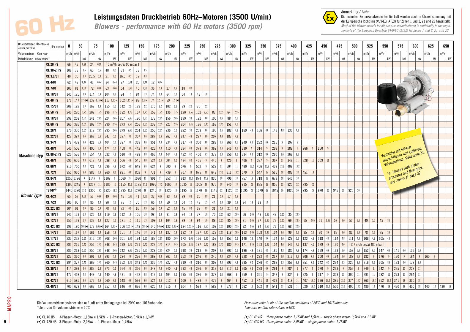
CL 20 HS 66 43 0,28 24 0,28 [ 0 m3/h bei/at 90 mbar ]
CL 30-Z HS 108 78 0,5 63 0,5 48 0,5 33 0,5 18 0,5
CL 3.6/01 40 30 0,3 25,5 0,3 21 0,3 16,5 0,3 12 0,3
CL 4/01 62 48 0,44 41 0,44 34 0,44 27 0,44 20 0,44 12 0,44
CL 7/01 100 81 0,66 72 0,66 63 0,66 54 0,66 45 0,66 36 0,9 27 0,9 18 0,9
CL 10/01 145 125 0,9 114 0,9 104 0,9 94 1,3 84 1,3 74 1,3 64 1,3 54 1,8 43 1,8
CL 40 HS 176 147 1,15 (•) 132 1,15 (•) 117 1,15 (•) 102 1,15 (•) 88 1,5 (•) 74 1,5 (•) 59 1,5 (•)
CL 15/01 208 182 1,3 168 1,3 155 1,3 142 2,2 129 2,2 115 2,2 102 2,2 89 2,2 76 2,2
CL 50 HS 240 220 1,75 208 1,75 196 1,75 182 1,75 167 1,75 153 1,75 136 1,75 120 2,55 102 2,55 83 2,55 64 2,55
CL 18/01 292 258 2,65 241 2,65 224 2,65 207 2,65 190 2,65 173 2,65 156 2,65 139 3,6 122 3,6 105 3,6 88 3,6
CL 60 HS 360 326 2,55 308 2,55 290 2,55 273 2,55 256 2,55 238 2,55 221 2,55 204 3,45 186 3,45 168 3,45 151 4,6
CL 28/1 370 330 2,65 312 2,65 295 2,65 279 2,65 264 2,65 250 2,65 236 3,6 222 3,6 208 3,6 195 3,6 182 4,8 169 4,8 156 4,8 143 4,8 130 4,8
CL 22/01 427 387 3,6 367 3,6 347 3,6 327 3,6 307 3,6 287 3,6 267 4,8 247 4,8 227 4,8 207 4,8 187 4,8
CL 34/1 472 438 3,6 421 3,6 404 3,6 387 3,6 369 3,6 351 4,8 334 4,8 317 4,8 300 4,8 283 6,6 266 6,6 249 6,6 232 6,6 215 9 197 9
CL 40/1 540 506 3,6 490 3,6 474 3,6 458 3,6 442 4,8 426 4,8 410 4,8 394 6,6 378 6,6 362 6,6 346 6,6 330 9 314 9 298 9 282 9 266 9 250 9
CL 80-Z HS 620 576 4,8 554 4,8 532 4,8 510 4,8 488 4,8 466 4,8 444 4,8 422 6,3 400 6,3 378 6,3 356 8,6 334 8,6 312 8,6 290 8,6 268 8,6
CL 46/1 690 636 4,8 612 4,8 588 4,8 566 4,8 545 4,8 524 6,6 504 6,6 484 6,6 465 9 445 9 426 9 406 9 387 9 367 11 348 11 328 11 309 11
CL 60/1 810 750 4,8 721 4,8 696 4,8 672 6,6 648 6,6 624 9 600 9 576 9 552 9 528 11 504 11 480 13,2 456 13,2 432 13,2 408 13,2
CL 72/1 955 910 6,6 886 6,6 860 6,6 831 6,6 802 9 771 9 739 9 707 11 675 11 643 13,2 611 13,2 579 18 547 18 515 18 483 18 451 18
CL 84/1 1250 1186 9 1147 9 1108 9 1069 9 1030 11 991 11 952 11 913 13,2 874 13,2 835 18 796 18 757 18 718 18 679 18 640 18
CL 98/1 1305 1245 9 1217 11 1185 11 1155 13,2 1125 13,2 1095 13,2 1065 18 1035 18 1005 18 975 18 945 18 915 22 885 22 855 22 825 22 795 22
TBT/M® 1440 1380 13,2 1350 13,2 1320 13,2 1295 13,2 1270 18 1245 18 1220 18 1195 18 1170 18 1145 22 1120 22 1095 22 1070 22 1045 26 1020 26 995 26 970 26 945 30 920 30
CL 4/21 65 57 0,66 53 0,66 49 0,66 45 0,66 41 0,66 37 0,66 33 0,9 29 0,9 25 0,9 21 0,9 17 0,9
CL 7/21 100 90 1,3 85 1,3 80 1,3 75 1,3 70 1,3 65 1,3 59 1,3 54 1,3 49 1,3 44 1,8 39 1,8 34 1,8 28 1,8
CL 220 HS 104 91 0,9 85 0,9 78 0,9 72 0,9 65 0,9 59 0,9 52 0,9 45 0,9 38 0,9 31 0,9 21 0,9
CL 10/21 145 133 1,8 126 1,8 119 1,8 112 1,8 105 1,8 98 1,8 91 1,8 84 1,8 77 1,8 70 2,65 63 2,65 56 2,65 49 2,65 42 2,65 35 2,65
CL 12/21 150 139 1,3 133 1,3 127 1,3 121 1,3 115 1,3 109 1,8 104 1,8 99 1,8 94 1,8 89 2,65 85 2,65 81 2,65 77 2,65 73 2,65 69 2,65 65 2,65 61 2,65 57 3,6 53 3,6 49 3,6 45 3,6
CL 420 HS 196 180 2,05 (•) 172 2,05 (•) 164 2,05 (•) 156 2,05 (•) 148 2,05 (•) 140 2,05 (•) 132 2,05 (•) 124 2,05 (•) 116 2,55 108 2,55 100 2,55 92 2,55 84 2,55 76 2,55 68 2,55
CL 14/21 180 167 1,8 161 1,8 156 1,8 151 1,8 146 1,8 141 1,8 137 1,8 132 1,8 127 2,65 123 2,65 118 2,65 113 2,65 108 2,65 104 3,6 99 3,6 95 3,6 90 3,6 86 3,6 82 3,6 78 3,6 75 3,6
CL 17/21 235 222 2,65 215 2,65 208 2,65 201 2,65 194 2,65 187 2,65 180 2,65 173 2,65 166 2,65 159 3,6 153 3,6 146 3,6 140 3,6 134 3,6 128 3,6 123 4,8 118 4,8 114 4,8 111 4,8 108 4,8 105 4,8
CL 520 HS 282 265 3,45 256 3,45 248 3,45 239 3,45 231 3,45 222 3,45 214 3,45 205 3,45 197 3,45 188 3,45 180 3,45 171 3,45 163 3,45 154 4,6 146 4,6 137 4,6 129 4,6 120 4,6 [ 117 m3/h bei/at 480 mbar ]
CL 20/21 280 263 2,65 255 2,65 248 2,65 242 2,65 235 2,65 229 2,65 224 3,6 218 3,6 213 3,6 207 3,6 202 3,6 196 4,8 191 4,8 185 4,8 180 4,8 174 4,8 169 6,6 163 6,6 158 6,6 152 6,6 147 6,6 141 6,6 136 6,6
CL 23/21 327 310 3,6 301 3,6 293 3,6 284 3,6 276 3,6 268 3,6 261 3,6 253 3,6 246 4,8 240 4,8 234 4,8 228 4,8 223 4,8 217 6,6 212 6,6 206 6,6 200 6,6 194 6,6 188 6,6 182 9 176 9 170 9 164 9 160 9
CL 720 HS 394 377 3,45 369 3,45 360 3,45 352 3,45 343 3,45 335 3,45 327 4,8 319 4,8 310 4,8 302 4,8 293 4,8 285 6,3 276 6,3 268 6,3 259 6,3 251 6,3 242 6,3 234 6,3 225 8,6 216 8,6 205 8,6 193 8,6 178 8,6
CL 30/21 414 393 3,6 383 3,6 373 3,6 364 3,6 356 3,6 348 4,8 340 4,8 333 4,8 326 6,6 319 6,6 312 6,6 305 6,6 298 6,6 291 9 284 9 277 9 270 9 263 9 256 9 249 9 242 9 235 11 228 11
CL 36/21 477 458 4,8 449 4,8 440 4,8 431 4,8 422 4,8 413 6,6 404 6,6 395 6,6 386 6,6 377 6,6 368 9 359 9 351 9 342 9 334 9 325 9 317 9 308 11 300 11 291 11 282 11 273 11 264 11
CL 42/21 610 585 6,6 572 6,6 560 6,6 548 6,6 536 6,6 524 6,6 512 9 500 9 488 9 476 9 464 9 452 11 441 11 429 11 418 11 407 13,2 396 13,2 385 13,2 374 13,2 363 13,2 352 13,2 341 18 330 18
CL 49/21 700 678 6,6 667 6,6 657 6,6 646 6,6 636 6,6 625 6,6 615 9 604 9 594 9 583 9 573 9 562 11 552 11 541 11 531 11 520 13,2 510 13,2 500 13,2 490 13,2 480 18 470 18 460 18 450 18 440 18 430 18
Die Volumenströme beziehen sich auf Luft unter Bedingungen bei 20°C und 1013mbar abs.Toleranzen für Volumenströme: ± 10%
(•) CL 40 HS 3-Phasen-Motor: 1,15kW e 1,5kW - 1-Phasen-Motor: 0,9kW e 1,3kW(•) CL 420 HS 3-Phasen-Motor: 2,05kW - 1-Phasen-Motor: 1,75kW
Flow rates refer to air at the suction conditions of 20°C and 1013mbar abs.Tolerance on flow rate values: ±10%
(•) CL 40 HS three phase motor: 1,15kW and 1,5kW - single phase motor: 0,9kW and 1,3kW(•) CL 420 HS three phase motor: 2,05kW - single phase motor: 1,75kW
Leistungsdaten Druckbetrieb 60Hz–Motoren (3500 U/min)Blowers - performance with 60 Hz motors (3500 rpm)60 Hz
MAP
RO
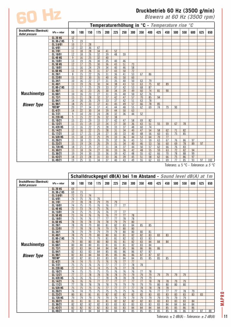
Druckbetrieb 60 Hz (3500 g/min)Blowers at 60 Hz (3500 rpm)60 Hz
Temperaturerhöhung in °C - Temperature rise °CDruckdifferenz (Überdruck)Outlet pressure
hPa = mbar 50 100 150 175 200 225 250 300 350 400 425 450 500 550 600 625 650
Maschinentyp
Blower Type
CL 20 HS 12CL 30-Z HS 9 19CL 3.6/01 10 17 28CL 4/01 12 22 36 47CL 7/01 11 18 28 34 41 52CL 10/01 12 18 26 32 39 48 59CL 40 HS 9 16 25 32 40CL 15/01 13 19 26 30 35 40 46CL 50 HS 12 17 25 30 36 43 51 73CL 18/01 11 16 24 29 34 40 46 58CL 60 HS 13 19 26 31 37 43 50 72CL 28/1 8 15 22 26 31 36 41 53 67 86CL 22/01 15 22 30 35 40 45 50 60CL 34/1 10 16 22 27 31 35 40 50 63 79CL 40/1 13 19 26 30 34 38 43 53 63 75 82 89CL 80-Z HS 13 17 25 29 33 37 42 53 68 87CL 46/1 11 16 23 26 30 34 39 49 60 74 81 90CL 60/1 10 16 23 27 31 35 40 50 62 76CL 72/1 15 21 28 32 37 42 47 57 70 85 94CL 84/1 14 20 26 29 33 37 42 51 63 78CL 98/1 18 25 33 37 41 45 49 57 66 78 85TBT/M® 20 27 34 37 41 44 48 55 62 69 74 79 90CL 4/21 14 22 30 34 39 44 50 63CL 7/21 9 14 20 24 28 32 36 44 52CL 220 HS 9 15 22 26 32 38CL 10/21 15 21 29 33 37 42 47 58 69 82CL 12/21 11 15 19 22 24 27 30 36 43 51 55 59 67 78CL 420 HS 13 16 22 25 28 33 37 48 60 74CL 14/21 12 16 22 25 28 31 34 40 47 54 58 62 71 82CL 17/21 13 17 21 24 27 30 33 40 48 56 60 65 75 85CL 520 HS 15 18 23 25 29 33 36 44 53 64 70 77CL 20/21 13 18 23 26 29 32 36 43 51 59 63 67 76 86 97CL 23/21 15 19 24 26 29 31 34 40 46 53 56 60 69 78 89 97CL 720 HS 18 21 25 27 31 34 37 44 50 57 62 66 76 83CL 30/21 13 18 24 27 30 33 36 42 48 55 59 63 72 82 94CL 36/21 19 24 30 33 36 39 42 48 55 62 66 70 78 88 99CL 42/21 18 23 28 31 33 36 39 45 51 58 62 66 75 86 97CL 49/21 19 25 31 34 37 40 43 49 55 62 65 69 77 85 93 97 102
Schalldruckpegel dB(A) bei 1m Abstand - Sound level dB(A) at 1mDruckdifferenz (Überdruck)Outlet pressure
hPa = mbar 50 100 150 175 200 225 250 300 350 400 425 450 500 550 600 625 650
Maschinentyp
Blower Type
CL 20 HS 69CL 30-Z HS 69 73CL 3.6/01 72 73 74CL 4/01 74 75 76 76CL 7/01 77 78 78 79 79 79CL 10/01 74 75 75 76 76 77 77CL 40 HS 72 73 74 75 76CL 15/01 74 75 75 76 76 77 77CL 50 HS 73 74 76 76 76 77 77 78CL 18/01 75 76 76 77 77 77 78 78CL 60 HS 78 78 78 78 78 79 79 80CL 28/1 78 78 79 80 81 82 83 84 85 85CL 22/01 77 78 78 78 79 79 80 80CL 34/1 78 79 79 79 79 79 80 80 80 81CL 40/1 78 79 79 80 80 81 81 82 82 83 83 83CL 80-Z HS 78 79 79 79 81 81 82 82 83 83CL 46/1 79 80 80 80 80 81 81 82 83 84 84 84CL 60/1 80 80 80 81 81 81 81 82 83 84CL 72/1 82 83 84 84 84 84 85 86 86 86 86CL 84/1 82 83 83 84 85 85 86 86 87 87CL 98/1 82 83 84 84 85 85 86 86 87 87 87TBT/M® 82 82 83 83 83 83 84 84 85 85 85 85CL 4/21 74 74 75 75 76 76 77 77CL 7/21 75 75 76 76 77 77 77 78 78CL 220 HS 72 73 74 74 75 76 77 78CL 10/21 74 75 75 75 75 76 76 76 77 78CL 12/21 77 77 78 78 78 78 79 79 79 79 79 79 79 79CL 420 HS 76 76 76 77 78 78 78 78 79 79CL 14/21 76 76 76 77 77 77 77 77 77 78 78 78 79 79CL 17/21 77 78 78 78 78 79 79 79 79 79 80 80 80 80CL 520 HS 75 75 75 76 77 77 77 77 78 78 78 78CL 20/21 74 74 75 75 75 75 75 76 76 76 77 77 77 78 79CL 23/21 80 81 81 81 82 82 82 82 82 83 83 83 83 83 83 83CL 720 HS 79 79 79 79 79 79 79 79 79 79 79 79 79 79CL 30/21 81 81 81 81 81 82 82 82 82 83 83 83 83 83 84CL 36/21 82 82 82 82 83 83 83 83 83 83 83 84 84 84 84CL 42/21 82 82 82 82 83 83 83 84 84 84 84 85 85 86 86CL 49/21 82 83 84 84 84 84 85 85 85 85 85 85 86 86 87 87 88 5
0 H
z
1,11,5
4
7,55,5
5,5
0,550,8
1,12,2
3
4
3
4
3
4
4,3
5,55,5
7,5
33
2,2
2,2
2,2
1,5
2,2
1,5
5,5
0,55
0,40,37
0,75
1,1
1,1
1,5
3
2,2
1,5
2,2
3
2,2
3
0,75
2,2
2,2
1,51,6
1,11,1
0,25
0,9
2,2
3
3
3
4
4
3
4
5,5
7,5
4
4
5,5
5,5
7,5
7,5
9,2
7,5
9,2
11
15
3
4
4
5,5
5,5
7,5
5,5
7,5
9,2
11
15
11
15
18,5
5,5
9,27,5
4
0,22
3,6/01
4/01
7/01
10/01
220H
S15
/01
50HS
18/01
420H
S
60HS
34/1
80-Z
HS
40/1
22/01
46/1
60/1
72/1
4/217/2
1
17/21
20/21
23/21
720H
S
30/21
36/21
49/21
20HS
30-Z
HS
98/1
84/1
TBT/M
®
42/21
28/152
0HS
10/21
12/21
14/21
40HS
2060
100
200
300
400
500
550
650
600
700
800
900
4080
150
250
350
450
1000
1200
1100
1300
50100
150
200
250
300
350
400
450
500
550
600
650
0
50100
150
200
250
300
350
400
450
500
550
600
650
Druckdifferenz (Unterdruck) [hPa = mbar]Inlet vacuum [hPa = mbar]
Volu
men
stro
m [
m3 /h
]Fl
ow ra
te
[m3 /h
]
Vol
umen
stro
m-V
akuu
m D
iagr
amm
F
low
rat
e-va
cuum
dia
gram
Die
Volu
men
strö
me
bezie
hen
sich
auf
Luf
t auf
das
jewe
ilige
Ans
augv
akuu
m b
ei 2
0°C;
am
Out
let w
urde
n 10
13m
bar a
bs. b
erüc
ksic
htig
t.Fl
ow ra
tes
refe
r to
air a
t the
suc
tion
pres
sure
and
20°
C an
d wi
th d
isch
arge
pre
ssur
e of
101
3 m
bar a
bs.
Verdichter mit höherer
Druckdifferenz und größerem
Volumenstrom, siehe Seite 32.
For blowers with higher
pressures and flow rates,
see curves at page 32
hPa = mbar
Anm
erku
ng /
Note
:Di
e m
eins
ten
Seite
nkan
alve
rdic
hter
für
Luf
t wu
rden
auc
h in
Übe
rein
stim
mun
g m
it de
r Eur
opäi
sche
Ric
htlin
ie 9
4/9/
EG (A
TEX)
für Z
onen
1 u
nd 2
, 21
und
22 h
erge
stel
lt.M
ost
of t
he e
xhau
ster
mod
els
for
air
are
also
man
ufac
ture
d in
con
form
ity t
o th
e re
quire
men
ts o
f the
Eur
opea
n Di
rect
ive
94/9
/EC
(ATE
X) fo
r Zon
es 1
and
2, 2
1 an
d 22
.Anmerkung / Note:Die meinsten Seitenkanalverdichter für Luft wurden auch in Übereinstimmung mit der Europäische Richtlinie 94/9/EG (ATEX) für Zonen 1 und 2, 21 und 22 hergestellt.Most of the blower models for air are also manufactured in conformity to the requi-rements of the European Directive 94/9/EC (ATEX) for Zones 1 and 2, 21 and 22.
Toleranz: ± 5 °C - Tolerance: ± 5 °C
Toleranz: ± 2 dB(A) - Tolerance: ± 2 dB(A)
Lege
nde
Key
Masc
hine
ntyp
Ma
chin
e ty
peMo
torle
istun
g (k
W)
Moto
r pow
er (k
W)
60/1
7,5
11
MAP
RO
Druckbetrieb 60 Hz (3500 g/min)Blowers at 60 Hz (3500 rpm)60 Hz
Temperaturerhöhung in °C - Temperature rise °CDruckdifferenz (Überdruck)Outlet pressure
hPa = mbar 50 100 150 175 200 225 250 300 350 400 425 450 500 550 600 625 650
Maschinentyp
Blower Type
CL 20 HS 12CL 30-Z HS 9 19CL 3.6/01 10 17 28CL 4/01 12 22 36 47CL 7/01 11 18 28 34 41 52CL 10/01 12 18 26 32 39 48 59CL 40 HS 9 16 25 32 40CL 15/01 13 19 26 30 35 40 46CL 50 HS 12 17 25 30 36 43 51 73CL 18/01 11 16 24 29 34 40 46 58CL 60 HS 13 19 26 31 37 43 50 72CL 28/1 8 15 22 26 31 36 41 53 67 86CL 22/01 15 22 30 35 40 45 50 60CL 34/1 10 16 22 27 31 35 40 50 63 79CL 40/1 13 19 26 30 34 38 43 53 63 75 82 89CL 80-Z HS 13 17 25 29 33 37 42 53 68 87CL 46/1 11 16 23 26 30 34 39 49 60 74 81 90CL 60/1 10 16 23 27 31 35 40 50 62 76CL 72/1 15 21 28 32 37 42 47 57 70 85 94CL 84/1 14 20 26 29 33 37 42 51 63 78CL 98/1 18 25 33 37 41 45 49 57 66 78 85TBT/M® 20 27 34 37 41 44 48 55 62 69 74 79 90CL 4/21 14 22 30 34 39 44 50 63CL 7/21 9 14 20 24 28 32 36 44 52CL 220 HS 9 15 22 26 32 38CL 10/21 15 21 29 33 37 42 47 58 69 82CL 12/21 11 15 19 22 24 27 30 36 43 51 55 59 67 78CL 420 HS 13 16 22 25 28 33 37 48 60 74CL 14/21 12 16 22 25 28 31 34 40 47 54 58 62 71 82CL 17/21 13 17 21 24 27 30 33 40 48 56 60 65 75 85CL 520 HS 15 18 23 25 29 33 36 44 53 64 70 77CL 20/21 13 18 23 26 29 32 36 43 51 59 63 67 76 86 97CL 23/21 15 19 24 26 29 31 34 40 46 53 56 60 69 78 89 97CL 720 HS 18 21 25 27 31 34 37 44 50 57 62 66 76 83CL 30/21 13 18 24 27 30 33 36 42 48 55 59 63 72 82 94CL 36/21 19 24 30 33 36 39 42 48 55 62 66 70 78 88 99CL 42/21 18 23 28 31 33 36 39 45 51 58 62 66 75 86 97CL 49/21 19 25 31 34 37 40 43 49 55 62 65 69 77 85 93 97 102
Schalldruckpegel dB(A) bei 1m Abstand - Sound level dB(A) at 1mDruckdifferenz (Überdruck)Outlet pressure
hPa = mbar 50 100 150 175 200 225 250 300 350 400 425 450 500 550 600 625 650
Maschinentyp
Blower Type
CL 20 HS 69CL 30-Z HS 69 73CL 3.6/01 72 73 74CL 4/01 74 75 76 76CL 7/01 77 78 78 79 79 79CL 10/01 74 75 75 76 76 77 77CL 40 HS 72 73 74 75 76CL 15/01 74 75 75 76 76 77 77CL 50 HS 73 74 76 76 76 77 77 78CL 18/01 75 76 76 77 77 77 78 78CL 60 HS 78 78 78 78 78 79 79 80CL 28/1 78 78 79 80 81 82 83 84 85 85CL 22/01 77 78 78 78 79 79 80 80CL 34/1 78 79 79 79 79 79 80 80 80 81CL 40/1 78 79 79 80 80 81 81 82 82 83 83 83CL 80-Z HS 78 79 79 79 81 81 82 82 83 83CL 46/1 79 80 80 80 80 81 81 82 83 84 84 84CL 60/1 80 80 80 81 81 81 81 82 83 84CL 72/1 82 83 84 84 84 84 85 86 86 86 86CL 84/1 82 83 83 84 85 85 86 86 87 87CL 98/1 82 83 84 84 85 85 86 86 87 87 87TBT/M® 82 82 83 83 83 83 84 84 85 85 85 85CL 4/21 74 74 75 75 76 76 77 77CL 7/21 75 75 76 76 77 77 77 78 78CL 220 HS 72 73 74 74 75 76 77 78CL 10/21 74 75 75 75 75 76 76 76 77 78CL 12/21 77 77 78 78 78 78 79 79 79 79 79 79 79 79CL 420 HS 76 76 76 77 78 78 78 78 79 79CL 14/21 76 76 76 77 77 77 77 77 77 78 78 78 79 79CL 17/21 77 78 78 78 78 79 79 79 79 79 80 80 80 80CL 520 HS 75 75 75 76 77 77 77 77 78 78 78 78CL 20/21 74 74 75 75 75 75 75 76 76 76 77 77 77 78 79CL 23/21 80 81 81 81 82 82 82 82 82 83 83 83 83 83 83 83CL 720 HS 79 79 79 79 79 79 79 79 79 79 79 79 79 79CL 30/21 81 81 81 81 81 82 82 82 82 83 83 83 83 83 84CL 36/21 82 82 82 82 83 83 83 83 83 83 83 84 84 84 84CL 42/21 82 82 82 82 83 83 83 84 84 84 84 85 85 86 86CL 49/21 82 83 84 84 84 84 85 85 85 85 85 85 86 86 87 87 88
Toleranz: ± 5 °C - Tolerance: ± 5 °C
Toleranz: ± 2 dB(A) - Tolerance: ± 2 dB(A)
Vaku
umbe
trie
b 50
Hz-
Mot
oren
(29
00 U
/min
)Ex
haus
ters
with
50
Hz
mot
ors
(290
0 rp
m)
MAP
RO
12 50 H
z
1,11,5
4
7,55,5
5,5
0,550,8
1,12,2
3
4
3
4
3
4
4,3
5,55,5
7,5
33
2,2
2,2
2,2
1,5
2,2
1,5
5,5
0,55
0,40,37
0,75
1,1
1,1
1,5
3
2,2
1,5
2,2
3
2,2
3
0,75
2,2
2,2
1,51,6
1,11,1
0,25
0,9
2,2
3
3
3
4
4
3
4
5,5
7,5
4
4
5,5
5,5
7,5
7,5
9,2
7,5
9,2
11
15
3
4
4
5,5
5,5
7,5
5,5
7,5
9,2
11
15
11
15
18,5
5,5
9,27,5
4
0,22
3,6/01
4/01
7/01
10/01
220H
S15
/01
50HS
18/01
420H
S
60HS
34/1
80-Z
HS
40/1
22/01
46/1
60/1
72/1
4/217/2
1
17/21
20/21
23/21
720H
S
30/21
36/21
49/21
20HS
30-Z
HS
98/1
84/1
TBT/M
®
42/21
28/152
0HS
10/21
12/21
14/21
40HS
2060
100
200
300
400
500
550
650
600
700
800
900
4080
150
250
350
450
1000
1200
1100
1300
50100
150
200
250
300
350
400
450
500
550
600
650
0
50100
150
200
250
300
350
400
450
500
550
600
650
Druckdifferenz (Unterdruck) [hPa = mbar]Inlet vacuum [hPa = mbar]
Volu
men
stro
m [
m3 /h
]Fl
ow ra
te
[m3 /h
]
Vol
umen
stro
m-V
akuu
m D
iagr
amm
F
low
rat
e-va
cuum
dia
gram
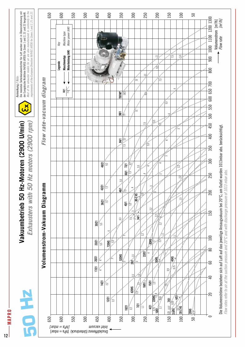
Die
Volu
men
strö
me
bezie
hen
sich
auf
Luf
t auf
das
jewe
ilige
Ans
augv
akuu
m b
ei 2
0°C;
am
Out
let w
urde
n 10
13m
bar a
bs. b
erüc
ksic
htig
t.Fl
ow ra
tes
refe
r to
air a
t the
suc
tion
pres
sure
and
20°
C an
d wi
th d
isch
arge
pre
ssur
e of
101
3 m
bar a
bs.
Anm
erku
ng /
Note
:Di
e m
eins
ten
Seite
nkan
alve
rdic
hter
für
Luf
t wu
rden
auc
h in
Übe
rein
stim
mun
g m
it de
r Eur
opäi
sche
Ric
htlin
ie 9
4/9/
EG (A
TEX)
für Z
onen
1 u
nd 2
, 21
und
22 h
erge
stel
lt.M
ost
of t
he e
xhau
ster
mod
els
for
air
are
also
man
ufac
ture
d in
con
form
ity t
o th
e re
quire
men
ts o
f the
Eur
opea
n Di
rect
ive
94/9
/EC
(ATE
X) fo
r Zon
es 1
and
2, 2
1 an
d 22
.
Lege
nde
Key
Masc
hine
ntyp
Ma
chin
e ty
peMo
torle
istun
g (k
W)
Moto
r pow
er (k
W)
60/1
7,5
13
MAP
RO
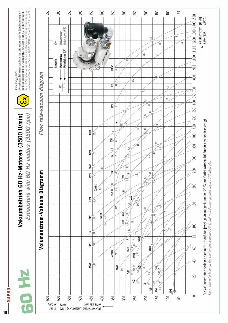
Vaku
umbe
trie
b 60
Hz-
Mot
oren
(35
00 U
/min
)Ex
haus
ters
with
60
Hz
mot
ors
(350
0 rp
m)
MAP
RO
15 16
Druckdifferenz (Unterdruck)Inlet vacuum
0 50 75 100 125 150 175 200 225 250 275 300 325 350 375 400 425 450 475 500 525 550 575 600 625 650
Volumenstrom - Flow rate m3/h m3/h m3/h m3/h m3/h m3/h m3/h m3/h m3/h m3/h m3/h m3/h m3/h m3/h m3/h m3/h m3/h m3/h m3/h m3/h m3/h m3/h m3/h m3/h m3/h m3/h
Motorleistung - Motor power kW kW kW kW kW kW kW kW kW kW kW kW kW kW kW kW kW kW kW kW kW kW kW kW kW
Maschinentyp
ExhausterType
CL 20 HS 54 19 0,22 [ 0 m3/h bei/at 60 mbar ]
CL 30-Z HS 84 52 0,4 36 0,4 20,5 0,4 [ 8 m3/h bei/at 120 mbar ]
CL 3.6/01 35 24 0,25 18 0,25 13,0 0,25 7,5 0,25 2 0,25
CL 4/01 52 36 0,37 28 0,37 20 0,37 12 0,37 4 0,37
CL 7/01 80 57 0,55 45 0,55 34 0,55 22 0,55 10 0,55
CL 10/01 120 92 0,75 78 0,75 64 0,75 50 0,75 37 1,1 23 1,1 7 1,1
CL 40 HS 150 120 0,9 (•) 104 0,9 (•) 85 0,9 (•) 68 0,9 (•) 48 0,9 (•) 28 1,1
CL 15/01 176 146 1,1 130 1,1 115 1,1 100 1,1 85 1,5 70 1,5 52 1,5 32 1,5
CL 50 HS 212 182 1,5 167 1,5 150 1,5 132 1,5 108 1,5 86 1,5 60 1,5
CL 18/01 252 214 1,5 197 1,5 179 1,5 161 2,2 142 2,2 122 2,2 98 2,2 70 3 32 3
CL 60 HS 300 271 2,2 252 2,2 231 2,2 210 2,2 188 2,2 162 2,2 131 2,2 90 3
CL 28/1 310 267 2,2 246 2,2 225 2,2 204 2,2 183 2,2 162 2,2 142 2,2 122 3 102 3 82 3 62 3
CL 22/01 346 292 2,2 268 2,2 244 2,2 220 3 195 3 168 3 138 3 106 4 74 4
CL 34/1 380 340 2,2 320 2,2 300 2,2 280 2,2 260 3 240 3 220 3 200 3 180 4 160 4 140 4
CL 40/1 454 414 3 395 3 375 3 356 3 336 3 317 3 297 4 275 4 253 4 229 5,5 204 5,5 170 5,5
CL 80-Z HS 518 464 4 436 4 408 4 380 4 352 4 324 4 296 4 268 5,5 235 5,5 195 5,5 150 7,5
CL 46/1 575 520 3 492 3 465 3 438 3 411 4 384 4 357 5,5 330 5,5 304 5,5 278 5,5 252 7,5 226 7,5 200 7,5
CL 60/1 685 625 4 595 4 565 4 535 4 505 4 475 5,5 445 5,5 415 7,5 385 7,5 345 7,5 305 7,5 260 7,5
CL 72/1 820 760 4 726 4 692 4 658 4 622 5,5 584 5,5 545 7,5 504 7,5 459 7,5 408 9,2 350 9,2 286 9,2
CL 84/1 1065 995 5,5 958 5,5 920 5,5 880 7,5 840 7,5 797 7,5 750 7,5 700 9,2 650 9,2 595 11 530 11 455 15 375 15
CL 98/1 1120 1080 7,5 1050 7,5 1020 7,5 985 7,5 945 7,5 906 9,2 860 9,2 810 11 755 11 698 15 637 15 574 15,0 505 15,0
TBT/M® 1235 1155 11 1115 11 1075 11 1035 11 995 11 955 11 915 11 875 15 835 15 790 15 740 15,0 690 18,5 640 18,5
CL 4/21 54 45 0,55 40 0,55 35 0,55 30 0,55 25 0,55 19 0,55 13 0,55 7 0,75
CL 7/21 80 67 1,1 60 1,1 54 1,1 47 1,1 41 1,1 34 1,1 28 1,1 21 1,1 15 1,1 8 1,1
CL 220 HS 86 69,5 0,8 61 0,8 53 0,8 45 0,8 36,5 0,8 28 0,8 20 0,8 8 0,8
CL 10/21 120 106 1,5 99 1,5 92 1,5 84 1,5 76 1,5 68 1,5 60 1,5 51 1,5 42 1,5 32 1,5 20 2,2 6 2,2
CL 12/21 130 115 1,1 107 1,1 100 1,1 93 1,1 85 1,1 78 1,1 70 1,5 63 1,5 55 1,5 48 1,5 40 1,5 33 2,2 27 2,2 21 2,2 15 2,2
CL 420 HS 154 138 1,6 (•) 129 1,6 (•) 120 1,6 (•) 111 1,6 (•) 101 1,6 (•) 91 1,6 (•) 80 1,6 (•) 67 1,6 (•) 54 1,6 (•) 39 1,6 (•) 22 2,2
CL 14/21 160 143 1,1 135 1,1 128 1,1 120 1,1 112 1,1 105 1,1 97 1,5 90 1,5 82 1,5 75 1,5 67 1,5 60 2,2 53 2,2 46 2,2 39 2,2 33 2,2
CL 17/21 205 188 2,2 179 2,2 171 2,2 162 2,2 153 2,2 145 2,2 136 2,2 127 2,2 118 2,2 110 2,2 101 3 92 3 84 3 75 3 67 3 58 4 50 4
CL 520 HS 236 216 3 206 3 196 3 186 3 176 3 166 3 156 3 144 3 131 3 117 3 102 3 83 3 60 3
CL 20/21 235 220 2,2 211 2,2 202 2,2 193 2,2 184 2,2 174 2,2 164 2,2 154 2,2 144 3 134 3 124 3 114 3 104 3 94 4 84 4 74 4 64 4
CL 23/21 280 258 3 247 3 237 3 226 3 216 3 206 3 195 3 185 3 174 3 164 3 153 3 143 4 132 4 121 4 111 4 100 5,5 90 5,5
CL 720 HS 324 300 3 288 3 276 3 264 3 252 3 240 3 227 3 213 3 200 4,3 185 4,3 169 4,3 152 4,3 133 4,3 113 5,5 90 5,5
CL 30/21 350 327 3 315 3 304 3 292 3 281 3 269 3 258 3 246 4 235 4 223 4 212 4 200 5,5 189 5,5 177 5,5 165 5,5 150 5,5 132 5,5
CL 36/21 410 390 4 379 4 368 4 355 4 342 4 328 4 313 4 298 4 284 4 270 5,5 255 5,5 241 5,5 226 5,5 211 7,5 195 7,5 178 7,5
CL 42/21 525 496 5,5 481 5,5 466 5,5 451 5,5 436 5,5 420 5,5 403 5,5 385 5,5 367 5,5 349 7,5 330 7,5 310 7,5 290 7,5 268 7,5 245 7,5 215 7,5
CL 49/21 600 564 5,5 551 5,5 538 5,5 525 5,5 510 5,5 494 5,5 476 5,5 458 5,5 440 7,5 422 7,5 403 7,5 384 7,5 365 7,5 344 9,2 328 9,2 300 9,2
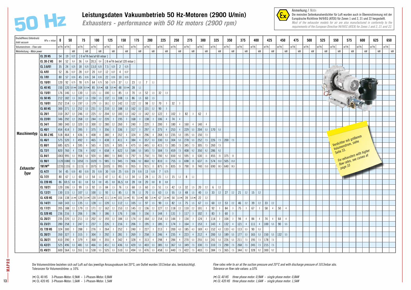
Die Volumenströme beziehen sich auf Luft auf das jeweilige Ansaugvakuum bei 20°C; am Outlet wurden 1013mbar abs. berücksichtigt. Toleranzen für Volumenströme: ± 10%
(•) CL 40 HS 3-Phasen-Motor: 0,9kW - 1-Phasen-Motor: 0,8kW(•) CL 420 HS 3-Phasen-Motor: 1,6kW - 1-Phasen-Motor: 1,5kW
Flow rates refer to air at the suction pressure and 20°C and with discharge pressure of 1013mbar abs.Tolerance on flow rate values: ±10%
(•) CL 40 HS three phase motor: 0,9kW - single phase motor: 0,8kW (•) CL 420 HS three phase motor: 1,6kW - single phase motor: 1,5kW
Leistungsdaten Vakuumbetrieb 50 Hz-Motoren (2900 U/min)Exhausters - performance with 50 Hz motors (2900 rpm)50 Hz
MAP
RO
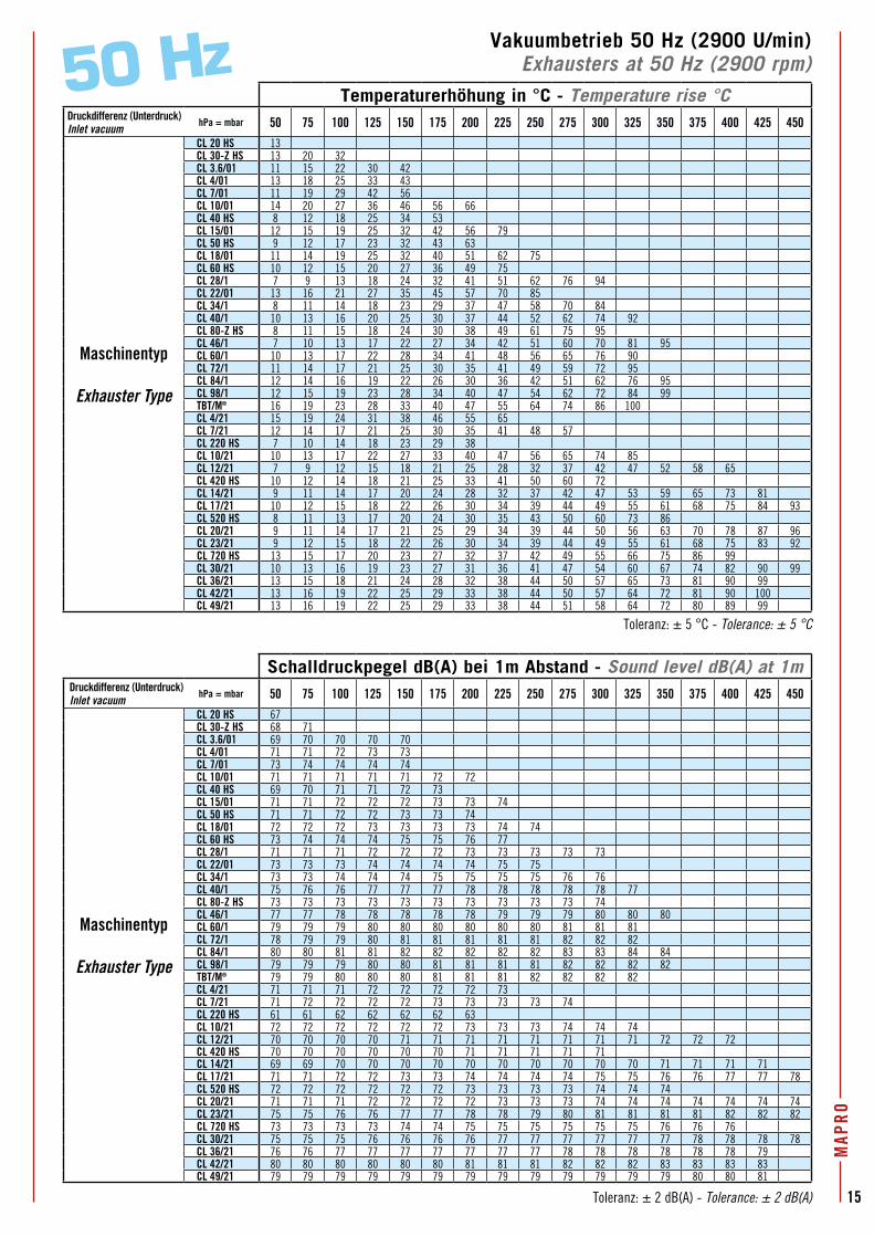
Vakuumbetrieb 50 Hz (2900 U/min)Exhausters at 50 Hz (2900 rpm)50 Hz
Temperaturerhöhung in °C - Temperature rise °CDruckdifferenz (Unterdruck)Inlet vacuum
hPa = mbar 50 75 100 125 150 175 200 225 250 275 300 325 350 375 400 425 450
Maschinentyp
Exhauster Type
CL 20 HS 13CL 30-Z HS 13 20 32CL 3.6/01 11 15 22 30 42CL 4/01 13 18 25 33 43CL 7/01 11 19 29 42 56CL 10/01 14 20 27 36 46 56 66CL 40 HS 8 12 18 25 34 53CL 15/01 12 15 19 25 32 42 56 79CL 50 HS 9 12 17 23 32 43 63CL 18/01 11 14 19 25 32 40 51 62 75CL 60 HS 10 12 15 20 27 36 49 75CL 28/1 7 9 13 18 24 32 41 51 62 76 94CL 22/01 13 16 21 27 35 45 57 70 85CL 34/1 8 11 14 18 23 29 37 47 58 70 84CL 40/1 10 13 16 20 25 30 37 44 52 62 74 92CL 80-Z HS 8 11 15 18 24 30 38 49 61 75 95CL 46/1 7 10 13 17 22 27 34 42 51 60 70 81 95CL 60/1 10 13 17 22 28 34 41 48 56 65 76 90CL 72/1 11 14 17 21 25 30 35 41 49 59 72 95CL 84/1 12 14 16 19 22 26 30 36 42 51 62 76 95CL 98/1 12 15 19 23 28 34 40 47 54 62 72 84 99TBT/M® 16 19 23 28 33 40 47 55 64 74 86 100CL 4/21 15 19 24 31 38 46 55 65CL 7/21 12 14 17 21 25 30 35 41 48 57CL 220 HS 7 10 14 18 23 29 38CL 10/21 10 13 17 22 27 33 40 47 56 65 74 85CL 12/21 7 9 12 15 18 21 25 28 32 37 42 47 52 58 65CL 420 HS 10 12 14 18 21 25 33 41 50 60 72CL 14/21 9 11 14 17 20 24 28 32 37 42 47 53 59 65 73 81CL 17/21 10 12 15 18 22 26 30 34 39 44 49 55 61 68 75 84 93CL 520 HS 8 11 13 17 20 24 30 35 43 50 60 73 86CL 20/21 9 11 14 17 21 25 29 34 39 44 50 56 63 70 78 87 96CL 23/21 9 12 15 18 22 26 30 34 39 44 49 55 61 68 75 83 92CL 720 HS 13 15 17 20 23 27 32 37 42 49 55 66 75 86 99CL 30/21 10 13 16 19 23 27 31 36 41 47 54 60 67 74 82 90 99CL 36/21 13 15 18 21 24 28 32 38 44 50 57 65 73 81 90 99CL 42/21 13 16 19 22 25 29 33 38 44 50 57 64 72 81 90 100CL 49/21 13 16 19 22 25 29 33 38 44 51 58 64 72 80 89 99
Schalldruckpegel dB(A) bei 1m Abstand - Sound level dB(A) at 1mDruckdifferenz (Unterdruck)Inlet vacuum
hPa = mbar 50 75 100 125 150 175 200 225 250 275 300 325 350 375 400 425 450
Maschinentyp
Exhauster Type
CL 20 HS 67CL 30-Z HS 68 71CL 3.6/01 69 70 70 70 70CL 4/01 71 71 72 73 73CL 7/01 73 74 74 74 74CL 10/01 71 71 71 71 71 72 72CL 40 HS 69 70 71 71 72 73CL 15/01 71 71 72 72 72 73 73 74CL 50 HS 71 71 72 72 73 73 74CL 18/01 72 72 72 73 73 73 73 74 74CL 60 HS 73 74 74 74 75 75 76 77CL 28/1 71 71 71 72 72 72 73 73 73 73 73CL 22/01 73 73 73 74 74 74 74 75 75CL 34/1 73 73 74 74 74 75 75 75 75 76 76CL 40/1 75 76 76 77 77 77 78 78 78 78 78 77CL 80-Z HS 73 73 73 73 73 73 73 73 73 73 74CL 46/1 77 77 78 78 78 78 78 79 79 79 80 80 80CL 60/1 79 79 79 80 80 80 80 80 80 81 81 81CL 72/1 78 79 79 80 81 81 81 81 81 82 82 82CL 84/1 80 80 81 81 82 82 82 82 82 83 83 84 84CL 98/1 79 79 79 80 80 81 81 81 81 82 82 82 82TBT/M® 79 79 80 80 80 81 81 81 82 82 82 82CL 4/21 71 71 71 72 72 72 72 73CL 7/21 71 72 72 72 72 73 73 73 73 74CL 220 HS 61 61 62 62 62 62 63CL 10/21 72 72 72 72 72 72 73 73 73 74 74 74CL 12/21 70 70 70 70 71 71 71 71 71 71 71 71 72 72 72CL 420 HS 70 70 70 70 70 70 71 71 71 71 71CL 14/21 69 69 70 70 70 70 70 70 70 70 70 70 71 71 71 71CL 17/21 71 71 72 72 73 73 74 74 74 74 75 75 76 76 77 77 78CL 520 HS 72 72 72 72 72 72 73 73 73 73 74 74 74CL 20/21 71 71 71 72 72 72 72 73 73 73 74 74 74 74 74 74 74CL 23/21 75 75 76 76 77 77 78 78 79 80 81 81 81 81 82 82 82CL 720 HS 73 73 73 73 74 74 75 75 75 75 75 75 76 76 76CL 30/21 75 75 75 76 76 76 76 77 77 77 77 77 77 78 78 78 78CL 36/21 76 76 77 77 77 77 77 77 77 78 78 78 78 78 78 79CL 42/21 80 80 80 80 80 80 81 81 81 82 82 82 83 83 83 83CL 49/21 79 79 79 79 79 79 79 79 79 79 79 79 79 80 80 81 6
0 H
z
2,55
2,55
3,6
3,45
4,84,8
6,6
6,69
11
3,6
3,6
4,8
8,6
6,6
6,3
4,8
6,6
9
6,6
913
,211
2,65
4,8
6,3
3,6
6,6
4,8
6,6
6,6
9
9
11
13,2
9
11
13,2
18
4,86,6
9
11
6,6
9
11
13,2
18
13,2
18
22
6,6
4,8
9
0,9
3,63,6
2,65
0,30,50,4
40,6
6
0,9
0,9
1,3
1,31,7
5
2,65
3,6
3,45
4,64,8
0,66
0,9
1,3
0,9
0,28
2,65
3,6
4,84,8 4,6
3,45
2,2
1,3
3,6
2,65
2,55
2,05
1,8
1,8
1,3
2,65
1,8
1,3
2,65
3,6
2,65
4,8
3,6/01
30-Z
HS
4/01
7/01
10/01
220 H
S
40HS
15/01
50HS
18/01
60HS
22/01
34/1
46/1
60/1
72/1
98/1
17/21
20/21
23/21
30/21
36/21
49/21
4/21
7/21
20HS
84/1
TBT/M
®
42/21
10/2112
/2114
/21
28/1
720 H
S
80-Z
HS
520 H
S
420 H
S40
/1
2060
100
200
300
400
500
550
650
600
700
800
900
4080
150
250
350
450
1000
1200
1100
50
1300
1400
150010
0
150
200
250
300
350
400
450
500
550
600
650
0
50100
150
200
250
300
350
400
450
500
550
600
650
Druckdifferenz (Unterdruck) [hPa = mbar]Inlet vacuum [hPa = mbar]
Volu
men
stro
m [
m3 /h
]Fl
ow ra
te
[m3 /h
]
60/1
11
Verdichter mit größerem
Volumenstrom, siehe
Seite 33.
For exhausters with higher
flow rates, see curves at
page 33
Anmerkung / Note:Die meinsten Seitenkanalverdichter für Luft wurden auch in Übereinstimmung mit der Europäische Richtlinie 94/9/EG (ATEX) für Zonen 1 und 2, 21 und 22 hergestellt.Most of the exhauster models for air are also manufactured in conformity to the requirements of the European Directive 94/9/EC (ATEX) for Zones 1 and 2, 21 and 22.
Anm
erku
ng /
Note
:Di
e m
eins
ten
Seite
nkan
alve
rdic
hter
für
Luf
t wu
rden
auc
h in
Übe
rein
stim
mun
g m
it de
r Eur
opäi
sche
Ric
htlin
ie 9
4/9/
EG (A
TEX)
für Z
onen
1 u
nd 2
, 21
und
22 h
erge
stel
lt.M
ost
of t
he e
xhau
ster
mod
els
for
air
are
also
man
ufac
ture
d in
con
form
ity t
o th
e re
quire
men
ts o
f the
Eur
opea
n Di
rect
ive
94/9
/EC
(ATE
X) fo
r Zon
es 1
and
2, 2
1 an
d 22
.
Vol
umen
stro
m-V
akuu
m D
iagr
amm
F
low
rat
e-va
cuum
dia
gram
Die
Volu
men
strö
me
bezie
hen
sich
auf
Luf
t auf
das
jewe
ilige
Ans
augv
akuu
m b
ei 2
0°C;
am
Out
let w
urde
n 10
13m
bar a
bs. b
erüc
ksic
htig
t.Fl
ow ra
tes
refe
r to
air a
t the
suc
tion
pres
sure
and
20°
C an
d wi
th d
isch
arge
pre
ssur
e of
101
3 m
bar a
bs.
hPa = mbar
Lege
nde
Key
Masc
hine
ntyp
Ma
chin
e ty
peMo
torle
istun
g (k
W)
Moto
r pow
er (k
W)
Toleranz: ± 5 °C - Tolerance: ± 5 °C
Toleranz: ± 2 dB(A) - Tolerance: ± 2 dB(A)
15
MAP
RO
Vakuumbetrieb 50 Hz (2900 U/min)Exhausters at 50 Hz (2900 rpm)50 Hz
Temperaturerhöhung in °C - Temperature rise °CDruckdifferenz (Unterdruck)Inlet vacuum
hPa = mbar 50 75 100 125 150 175 200 225 250 275 300 325 350 375 400 425 450
Maschinentyp
Exhauster Type
CL 20 HS 13CL 30-Z HS 13 20 32CL 3.6/01 11 15 22 30 42CL 4/01 13 18 25 33 43CL 7/01 11 19 29 42 56CL 10/01 14 20 27 36 46 56 66CL 40 HS 8 12 18 25 34 53CL 15/01 12 15 19 25 32 42 56 79CL 50 HS 9 12 17 23 32 43 63CL 18/01 11 14 19 25 32 40 51 62 75CL 60 HS 10 12 15 20 27 36 49 75CL 28/1 7 9 13 18 24 32 41 51 62 76 94CL 22/01 13 16 21 27 35 45 57 70 85CL 34/1 8 11 14 18 23 29 37 47 58 70 84CL 40/1 10 13 16 20 25 30 37 44 52 62 74 92CL 80-Z HS 8 11 15 18 24 30 38 49 61 75 95CL 46/1 7 10 13 17 22 27 34 42 51 60 70 81 95CL 60/1 10 13 17 22 28 34 41 48 56 65 76 90CL 72/1 11 14 17 21 25 30 35 41 49 59 72 95CL 84/1 12 14 16 19 22 26 30 36 42 51 62 76 95CL 98/1 12 15 19 23 28 34 40 47 54 62 72 84 99TBT/M® 16 19 23 28 33 40 47 55 64 74 86 100CL 4/21 15 19 24 31 38 46 55 65CL 7/21 12 14 17 21 25 30 35 41 48 57CL 220 HS 7 10 14 18 23 29 38CL 10/21 10 13 17 22 27 33 40 47 56 65 74 85CL 12/21 7 9 12 15 18 21 25 28 32 37 42 47 52 58 65CL 420 HS 10 12 14 18 21 25 33 41 50 60 72CL 14/21 9 11 14 17 20 24 28 32 37 42 47 53 59 65 73 81CL 17/21 10 12 15 18 22 26 30 34 39 44 49 55 61 68 75 84 93CL 520 HS 8 11 13 17 20 24 30 35 43 50 60 73 86CL 20/21 9 11 14 17 21 25 29 34 39 44 50 56 63 70 78 87 96CL 23/21 9 12 15 18 22 26 30 34 39 44 49 55 61 68 75 83 92CL 720 HS 13 15 17 20 23 27 32 37 42 49 55 66 75 86 99CL 30/21 10 13 16 19 23 27 31 36 41 47 54 60 67 74 82 90 99CL 36/21 13 15 18 21 24 28 32 38 44 50 57 65 73 81 90 99CL 42/21 13 16 19 22 25 29 33 38 44 50 57 64 72 81 90 100CL 49/21 13 16 19 22 25 29 33 38 44 51 58 64 72 80 89 99
Schalldruckpegel dB(A) bei 1m Abstand - Sound level dB(A) at 1mDruckdifferenz (Unterdruck)Inlet vacuum
hPa = mbar 50 75 100 125 150 175 200 225 250 275 300 325 350 375 400 425 450
Maschinentyp
Exhauster Type
CL 20 HS 67CL 30-Z HS 68 71CL 3.6/01 69 70 70 70 70CL 4/01 71 71 72 73 73CL 7/01 73 74 74 74 74CL 10/01 71 71 71 71 71 72 72CL 40 HS 69 70 71 71 72 73CL 15/01 71 71 72 72 72 73 73 74CL 50 HS 71 71 72 72 73 73 74CL 18/01 72 72 72 73 73 73 73 74 74CL 60 HS 73 74 74 74 75 75 76 77CL 28/1 71 71 71 72 72 72 73 73 73 73 73CL 22/01 73 73 73 74 74 74 74 75 75CL 34/1 73 73 74 74 74 75 75 75 75 76 76CL 40/1 75 76 76 77 77 77 78 78 78 78 78 77CL 80-Z HS 73 73 73 73 73 73 73 73 73 73 74CL 46/1 77 77 78 78 78 78 78 79 79 79 80 80 80CL 60/1 79 79 79 80 80 80 80 80 80 81 81 81CL 72/1 78 79 79 80 81 81 81 81 81 82 82 82CL 84/1 80 80 81 81 82 82 82 82 82 83 83 84 84CL 98/1 79 79 79 80 80 81 81 81 81 82 82 82 82TBT/M® 79 79 80 80 80 81 81 81 82 82 82 82CL 4/21 71 71 71 72 72 72 72 73CL 7/21 71 72 72 72 72 73 73 73 73 74CL 220 HS 61 61 62 62 62 62 63CL 10/21 72 72 72 72 72 72 73 73 73 74 74 74CL 12/21 70 70 70 70 71 71 71 71 71 71 71 71 72 72 72CL 420 HS 70 70 70 70 70 70 71 71 71 71 71CL 14/21 69 69 70 70 70 70 70 70 70 70 70 70 71 71 71 71CL 17/21 71 71 72 72 73 73 74 74 74 74 75 75 76 76 77 77 78CL 520 HS 72 72 72 72 72 72 73 73 73 73 74 74 74CL 20/21 71 71 71 72 72 72 72 73 73 73 74 74 74 74 74 74 74CL 23/21 75 75 76 76 77 77 78 78 79 80 81 81 81 81 82 82 82CL 720 HS 73 73 73 73 74 74 75 75 75 75 75 75 76 76 76CL 30/21 75 75 75 76 76 76 76 77 77 77 77 77 77 78 78 78 78CL 36/21 76 76 77 77 77 77 77 77 77 78 78 78 78 78 78 79CL 42/21 80 80 80 80 80 80 81 81 81 82 82 82 83 83 83 83CL 49/21 79 79 79 79 79 79 79 79 79 79 79 79 79 80 80 81
Toleranz: ± 5 °C - Tolerance: ± 5 °C
Toleranz: ± 2 dB(A) - Tolerance: ± 2 dB(A)
Vaku
umbe
trie
b 60
Hz-
Mot
oren
(35
00 U
/min
)Ex
haus
ters
with
60
Hz
mot
ors
(350
0 rp
m)
MAP
RO
16 60 H
z
2,55
2,55
3,6
3,45
4,84,8
6,6
6,69
11
3,6
3,6
4,8
8,6
6,6
6,3
4,8
6,6
9
6,6
913
,211
2,65
4,8
6,3
3,6
6,6
4,8
6,6
6,6
9
9
11
13,2
9
11
13,2
18
4,86,6
9
11
6,6
9
11
13,2
18
13,2
18
22
6,6
4,8
9
0,9
3,63,6
2,65
0,30,50,4
40,6
6
0,9
0,9
1,3
1,31,7
5
2,65
3,6
3,45
4,64,8
0,66
0,9
1,3
0,9
0,28
2,65
3,6
4,84,8 4,6
3,45
2,2
1,3
3,6
2,65
2,55
2,05
1,8
1,8
1,3
2,65
1,8
1,3
2,65
3,6
2,65
4,8
3,6/01
30-Z
HS
4/01
7/01
10/01
220 H
S
40HS
15/01
50HS
18/01
60HS
22/01
34/1
46/1
60/1
72/1
98/1
17/21
20/21
23/21
30/21
36/21
49/21
4/21
7/21
20HS
84/1
TBT/M
®
42/21
10/2112
/2114
/21
28/1
720 H
S
80-Z
HS
520 H
S
420 H
S40
/1
2060
100
200
300
400
500
550
650
600
700
800
900
4080
150
250
350
450
1000
1200
1100
50
1300
1400
150010
0
150
200
250
300
350
400
450
500
550
600
650
0
50100
150
200
250
300
350
400
450
500
550
600
650
Druckdifferenz (Unterdruck) [hPa = mbar]Inlet vacuum [hPa = mbar]
Volu
men
stro
m [
m3 /h
]Fl
ow ra
te
[m3 /h
]
60/1
11
Anm
erku
ng /
Note
:Di
e m
eins
ten
Seite
nkan
alve
rdic
hter
für
Luf
t wu
rden
auc
h in
Übe
rein
stim
mun
g m
it de
r Eur
opäi
sche
Ric
htlin
ie 9
4/9/
EG (A
TEX)
für Z
onen
1 u
nd 2
, 21
und
22 h
erge
stel
lt.M
ost
of t
he e
xhau
ster
mod
els
for
air
are
also
man
ufac
ture
d in
con
form
ity t
o th
e re
quire
men
ts o
f the
Eur
opea
n Di
rect
ive
94/9
/EC
(ATE
X) fo
r Zon
es 1
and
2, 2
1 an
d 22
.
Vol
umen
stro
m-V
akuu
m D
iagr
amm
F
low
rat
e-va
cuum
dia
gram
Die
Volu
men
strö
me
bezie
hen
sich
auf
Luf
t auf
das
jewe
ilige
Ans
augv
akuu
m b
ei 2
0°C;
am
Out
let w
urde
n 10
13m
bar a
bs. b
erüc
ksic
htig
t.Fl
ow ra
tes
refe
r to
air a
t the
suc
tion
pres
sure
and
20°
C an
d wi
th d
isch
arge
pre
ssur
e of
101
3 m
bar a
bs.
Lege
nde
Key
Masc
hine
ntyp
Ma
chin
e ty
peMo
torle
istun
g (k
W)
Moto
r pow
er (k
W)
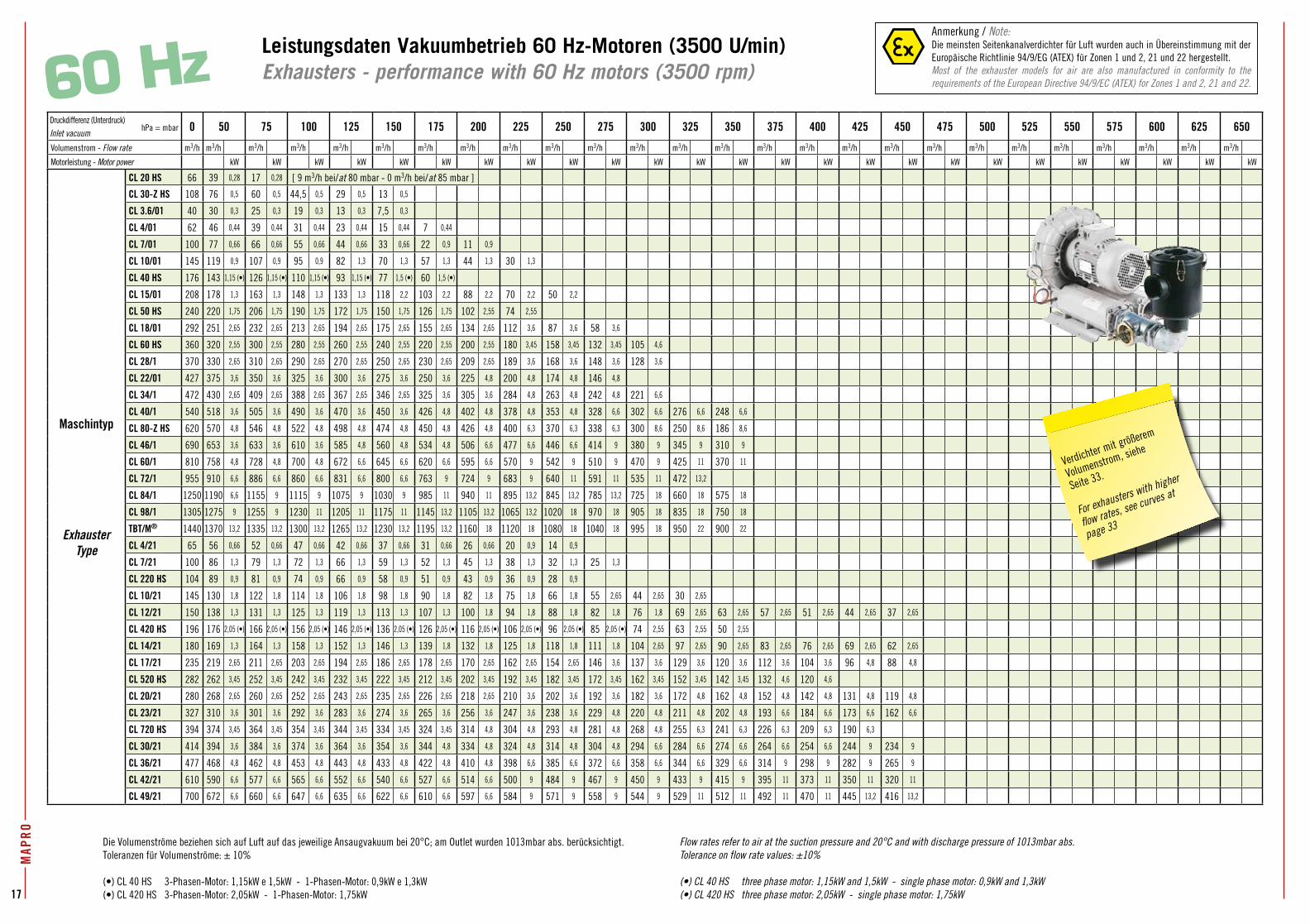
17
MAP
RO
19
Druckdifferenz (Unterdruck)Inlet vacuum
0 50 75 100 125 150 175 200 225 250 275 300 325 350 375 400 425 450 475 500 525 550 575 600 625 650
Volumenstrom - Flow rate m3/h m3/h m3/h m3/h m3/h m3/h m3/h m3/h m3/h m3/h m3/h m3/h m3/h m3/h m3/h m3/h m3/h m3/h m3/h m3/h m3/h m3/h m3/h m3/h m3/h m3/h
Motorleistung - Motor power kW kW kW kW kW kW kW kW kW kW kW kW kW kW kW kW kW kW kW kW kW kW kW kW kW
Maschintyp
ExhausterType
CL 20 HS 66 39 0,28 17 0,28 [ 9 m3/h bei/at 80 mbar - 0 m3/h bei/at 85 mbar ]
CL 30-Z HS 108 76 0,5 60 0,5 44,5 0,5 29 0,5 13 0,5
CL 3.6/01 40 30 0,3 25 0,3 19 0,3 13 0,3 7,5 0,3
CL 4/01 62 46 0,44 39 0,44 31 0,44 23 0,44 15 0,44 7 0,44
CL 7/01 100 77 0,66 66 0,66 55 0,66 44 0,66 33 0,66 22 0,9 11 0,9
CL 10/01 145 119 0,9 107 0,9 95 0,9 82 1,3 70 1,3 57 1,3 44 1,3 30 1,3
CL 40 HS 176 143 1,15 (•) 126 1,15 (•) 110 1,15 (•) 93 1,15 (•) 77 1,5 (•) 60 1,5 (•)
CL 15/01 208 178 1,3 163 1,3 148 1,3 133 1,3 118 2,2 103 2,2 88 2,2 70 2,2 50 2,2
CL 50 HS 240 220 1,75 206 1,75 190 1,75 172 1,75 150 1,75 126 1,75 102 2,55 74 2,55
CL 18/01 292 251 2,65 232 2,65 213 2,65 194 2,65 175 2,65 155 2,65 134 2,65 112 3,6 87 3,6 58 3,6
CL 60 HS 360 320 2,55 300 2,55 280 2,55 260 2,55 240 2,55 220 2,55 200 2,55 180 3,45 158 3,45 132 3,45 105 4,6
CL 28/1 370 330 2,65 310 2,65 290 2,65 270 2,65 250 2,65 230 2,65 209 2,65 189 3,6 168 3,6 148 3,6 128 3,6
CL 22/01 427 375 3,6 350 3,6 325 3,6 300 3,6 275 3,6 250 3,6 225 4,8 200 4,8 174 4,8 146 4,8
CL 34/1 472 430 2,65 409 2,65 388 2,65 367 2,65 346 2,65 325 3,6 305 3,6 284 4,8 263 4,8 242 4,8 221 6,6
CL 40/1 540 518 3,6 505 3,6 490 3,6 470 3,6 450 3,6 426 4,8 402 4,8 378 4,8 353 4,8 328 6,6 302 6,6 276 6,6 248 6,6
CL 80-Z HS 620 570 4,8 546 4,8 522 4,8 498 4,8 474 4,8 450 4,8 426 4,8 400 6,3 370 6,3 338 6,3 300 8,6 250 8,6 186 8,6
CL 46/1 690 653 3,6 633 3,6 610 3,6 585 4,8 560 4,8 534 4,8 506 6,6 477 6,6 446 6,6 414 9 380 9 345 9 310 9
CL 60/1 810 758 4,8 728 4,8 700 4,8 672 6,6 645 6,6 620 6,6 595 6,6 570 9 542 9 510 9 470 9 425 11 370 11
CL 72/1 955 910 6,6 886 6,6 860 6,6 831 6,6 800 6,6 763 9 724 9 683 9 640 11 591 11 535 11 472 13,2
CL 84/1 1250 1190 6,6 1155 9 1115 9 1075 9 1030 9 985 11 940 11 895 13,2 845 13,2 785 13,2 725 18 660 18 575 18
CL 98/1 1305 1275 9 1255 9 1230 11 1205 11 1175 11 1145 13,2 1105 13,2 1065 13,2 1020 18 970 18 905 18 835 18 750 18
TBT/M® 1440 1370 13,2 1335 13,2 1300 13,2 1265 13,2 1230 13,2 1195 13,2 1160 18 1120 18 1080 18 1040 18 995 18 950 22 900 22
CL 4/21 65 56 0,66 52 0,66 47 0,66 42 0,66 37 0,66 31 0,66 26 0,66 20 0,9 14 0,9
CL 7/21 100 86 1,3 79 1,3 72 1,3 66 1,3 59 1,3 52 1,3 45 1,3 38 1,3 32 1,3 25 1,3
CL 220 HS 104 89 0,9 81 0,9 74 0,9 66 0,9 58 0,9 51 0,9 43 0,9 36 0,9 28 0,9
CL 10/21 145 130 1,8 122 1,8 114 1,8 106 1,8 98 1,8 90 1,8 82 1,8 75 1,8 66 1,8 55 2,65 44 2,65 30 2,65
CL 12/21 150 138 1,3 131 1,3 125 1,3 119 1,3 113 1,3 107 1,3 100 1,8 94 1,8 88 1,8 82 1,8 76 1,8 69 2,65 63 2,65 57 2,65 51 2,65 44 2,65 37 2,65
CL 420 HS 196 176 2,05 (•) 166 2,05 (•) 156 2,05 (•) 146 2,05 (•) 136 2,05 (•) 126 2,05 (•) 116 2,05 (•) 106 2,05 (•) 96 2,05 (•) 85 2,05 (•) 74 2,55 63 2,55 50 2,55
CL 14/21 180 169 1,3 164 1,3 158 1,3 152 1,3 146 1,3 139 1,8 132 1,8 125 1,8 118 1,8 111 1,8 104 2,65 97 2,65 90 2,65 83 2,65 76 2,65 69 2,65 62 2,65
CL 17/21 235 219 2,65 211 2,65 203 2,65 194 2,65 186 2,65 178 2,65 170 2,65 162 2,65 154 2,65 146 3,6 137 3,6 129 3,6 120 3,6 112 3,6 104 3,6 96 4,8 88 4,8
CL 520 HS 282 262 3,45 252 3,45 242 3,45 232 3,45 222 3,45 212 3,45 202 3,45 192 3,45 182 3,45 172 3,45 162 3,45 152 3,45 142 3,45 132 4,6 120 4,6
CL 20/21 280 268 2,65 260 2,65 252 2,65 243 2,65 235 2,65 226 2,65 218 2,65 210 3,6 202 3,6 192 3,6 182 3,6 172 4,8 162 4,8 152 4,8 142 4,8 131 4,8 119 4,8
CL 23/21 327 310 3,6 301 3,6 292 3,6 283 3,6 274 3,6 265 3,6 256 3,6 247 3,6 238 3,6 229 4,8 220 4,8 211 4,8 202 4,8 193 6,6 184 6,6 173 6,6 162 6,6
CL 720 HS 394 374 3,45 364 3,45 354 3,45 344 3,45 334 3,45 324 3,45 314 4,8 304 4,8 293 4,8 281 4,8 268 4,8 255 6,3 241 6,3 226 6,3 209 6,3 190 6,3
CL 30/21 414 394 3,6 384 3,6 374 3,6 364 3,6 354 3,6 344 4,8 334 4,8 324 4,8 314 4,8 304 4,8 294 6,6 284 6,6 274 6,6 264 6,6 254 6,6 244 9 234 9
CL 36/21 477 468 4,8 462 4,8 453 4,8 443 4,8 433 4,8 422 4,8 410 4,8 398 6,6 385 6,6 372 6,6 358 6,6 344 6,6 329 6,6 314 9 298 9 282 9 265 9
CL 42/21 610 590 6,6 577 6,6 565 6,6 552 6,6 540 6,6 527 6,6 514 6,6 500 9 484 9 467 9 450 9 433 9 415 9 395 11 373 11 350 11 320 11
CL 49/21 700 672 6,6 660 6,6 647 6,6 635 6,6 622 6,6 610 6,6 597 6,6 584 9 571 9 558 9 544 9 529 11 512 11 492 11 470 11 445 13,2 416 13,2
Leistungsdaten Vakuumbetrieb 60 Hz-Motoren (3500 U/min)Exhausters - performance with 60 Hz motors (3500 rpm)60 Hz
MAP
RO
Vakuumbetrieb 60 Hz (3500 U/min)Exhausters at 60 Hz (3500 rpm)60 Hz
Temperaturerhöhung in °C - Temperature rise °CDruckdifferenz (Unterdruck)Inlet vacuum
hPa = mbar 50 75 100 125 150 175 200 225 250 275 300 325 350 375 400 425 450
Maschinentyp
Exhauster Type
CL 20 HS 15 23CL 30-Z HS 9 13 19CL 3.6/01 11 15 21 28 38CL 4/01 14 18 25 32 40 50CL 7/01 13 19 25 32 41 54 71CL 10/01 17 22 27 34 42 50 60 70CL 40 HS 9 12 17 22 28 39CL 15/01 13 15 18 22 27 36 46 60 82CL 50 HS 11 14 17 21 27 33 42 54CL 18/01 14 17 22 27 33 40 48 58 71 90CL 60 HS 12 15 18 22 26 32 38 46 56 67 80CL 28/1 8 11 15 19 24 30 36 46 57 71 90CL 22/01 15 19 24 29 35 43 53 64 76 94CL 34/1 8 11 14 18 23 28 35 42 50 60 74CL 40/1 11 13 16 20 24 29 35 41 48 55 64 75 88CL 80-Z HS 10 13 15 18 22 27 33 40 49 59 70 84 98CL 46/1 8 11 14 18 22 27 32 39 46 55 65 76 90CL 60/1 12 14 16 19 23 28 33 40 47 55 65 76 90CL 72/1 14 17 20 24 28 32 37 42 49 58 70 90CL 84/1 16 17 19 22 25 28 32 37 43 51 60 73 90CL 98/1 18 20 23 26 30 35 40 46 53 60 70 81 95TBT/M® 19 21 24 28 33 38 44 51 59 67 76 88CL 4/21 17 21 26 32 38 45 53 61 71CL 7/21 13 15 18 22 26 30 35 40 46 53CL 220 HS 9 11 14 18 23 18 34 41 49CL 10/21 14 17 20 23 27 32 37 43 51 60 69 80CL 12/21 10 11 13 15 17 20 23 27 31 35 40 45 50 56 62 69 77CL 420 HS 12 14 16 19 23 27 33 39 47 54 64 74CL 14/21 12 13 15 17 19 22 25 29 33 37 41 45 50 55 61 68 75CL 17/21 10 12 15 18 22 26 30 34 38 43 48 54 60 66 73 81 89CL 520 HS 11 13 15 17 20 24 27 31 36 42 48 55 64 75 87CL 20/21 12 14 17 20 24 28 32 36 41 47 52 58 64 70 76 85 94CL 23/21 12 15 18 21 24 28 32 36 40 45 50 55 60 66 73 81 90CL 720 HS 17 19 20 23 25 28 32 35 40 44 50 55 62 69 79 89CL 30/21 12 15 18 21 24 27 31 35 40 45 51 57 64 71 79 87 95CL 36/21 18 20 22 25 28 32 36 41 46 52 58 64 70 77 84 91 100CL 42/21 18 20 22 25 28 31 34 38 43 48 54 60 67 75 83 92 101CL 49/21 19 22 25 28 32 36 40 44 49 54 59 65 71 78 85 93 102
Schalldruckpegel dB(A) bei 1m Abstand - Sound level dB(A) at 1mDruckdifferenz (Unterdruck)Inlet vacuum
hPa = mbar 50 75 100 125 150 175 200 225 250 275 300 325 350 375 400 425 450
Maschinentyp
Exhauster Type
CL 20 HS 68 70CL 30-Z HS 68 71 72CL 3.6/01 71 71 72 72 73CL 4/01 74 74 75 75 76 76CL 7/01 76 76 77 77 78 78 79CL 10/01 73 73 73 73 73 74 74 74CL 40 HS 70 71 72 72 72 73CL 15/01 73 73 74 74 74 75 76 76 76CL 50 HS 71 72 72 72 73 73 74 74CL 18/01 74 74 75 75 75 76 76 76 77 77CL 60 HS 75 75 75 75 76 76 76 77 77 78 78CL 28/1 76 76 77 77 78 78 79 79 79 79 79CL 22/01 75 75 75 76 76 76 76 77 77 78CL 34/1 76 76 76 76 77 77 78 78 78 79 79CL 40/1 79 79 80 80 81 81 82 82 82 82 82 82 81CL 80-Z HS 76 76 76 76 76 76 76 76 76 76 77 77 77CL 46/1 80 80 80 81 81 82 82 82 83 83 83 84 84CL 60/1 81 81 81 82 82 83 83 83 83 83 84 84 84CL 72/1 82 82 82 83 83 83 84 84 84 85 85 86CL 84/1 82 82 82 83 83 83 84 84 85 85 85 86 86CL 98/1 82 82 83 83 83 84 84 84 85 85 86 86 86TBT/M® 81 81 82 82 82 83 83 83 84 84 84 84CL 4/21 73 73 73 73 73 74 74 75 75CL 7/21 73 73 73 73 73 74 74 75 75 75CL 220 HS 68 68 68 68 69 69 69 69 69CL 10/21 74 74 74 74 74 74 75 75 76 76 76 77CL 12/21 74 74 75 75 76 76 76 77 77 77 77 77 77 77 78 78 78CL 420 HS 73 73 73 73 73 73 73 73 73 73 73 74 74CL 14/21 74 74 75 75 76 76 77 77 77 77 77 77 77 77 77 77 78CL 17/21 73 73 73 74 74 74 75 75 75 76 76 77 78 78 79 79 79CL 520 HS 75 75 75 75 75 75 75 75 75 75 75 76 76 76 76CL 20/21 3 73 74 74 74 75 75 75 75 76 76 76 76 76 76 76 76CL 23/21 79 79 80 80 80 81 81 81 81 82 82 82 82 82 82 83 83CL 720 HS 77 77 77 78 78 78 78 78 78 78 79 79 79 79 79 79CL 30/21 79 80 80 80 81 81 81 81 81 82 82 82 82 82 82 83 83CL 36/21 81 81 82 82 82 82 82 82 82 83 83 83 83 83 83 83 83CL 42/21 81 81 81 81 82 82 82 83 83 83 84 84 84 84 85 85 85CL 49/21 82 82 83 83 83 83 83 83 83 83 84 84 84 84 85 85 85
Die Volumenströme beziehen sich auf Luft auf das jeweilige Ansaugvakuum bei 20°C; am Outlet wurden 1013mbar abs. berücksichtigt. Toleranzen für Volumenströme: ± 10%
(•) CL 40 HS 3-Phasen-Motor: 1,15kW e 1,5kW - 1-Phasen-Motor: 0,9kW e 1,3kW(•) CL 420 HS 3-Phasen-Motor: 2,05kW - 1-Phasen-Motor: 1,75kW
Flow rates refer to air at the suction pressure and 20°C and with discharge pressure of 1013mbar abs.Tolerance on flow rate values: ±10%
(•) CL 40 HS three phase motor: 1,15kW and 1,5kW - single phase motor: 0,9kW and 1,3kW(•) CL 420 HS three phase motor: 2,05kW - single phase motor: 1,75kW
Anmerkung / Note:Die meinsten Seitenkanalverdichter für Luft wurden auch in Übereinstimmung mit der Europäische Richtlinie 94/9/EG (ATEX) für Zonen 1 und 2, 21 und 22 hergestellt.Most of the exhauster models for air are also manufactured in conformity to the requirements of the European Directive 94/9/EC (ATEX) for Zones 1 and 2, 21 and 22.
Verdichter mit größerem
Volumenstrom, siehe
Seite 33.
For exhausters with higher
flow rates, see curves at
page 33
hPa = mbar
Toleranz: ± 5 °C - Tolerance: ± 5 °C
Toleranz: ± 2 dB(A) - Tolerance: ± 2 dB(A)
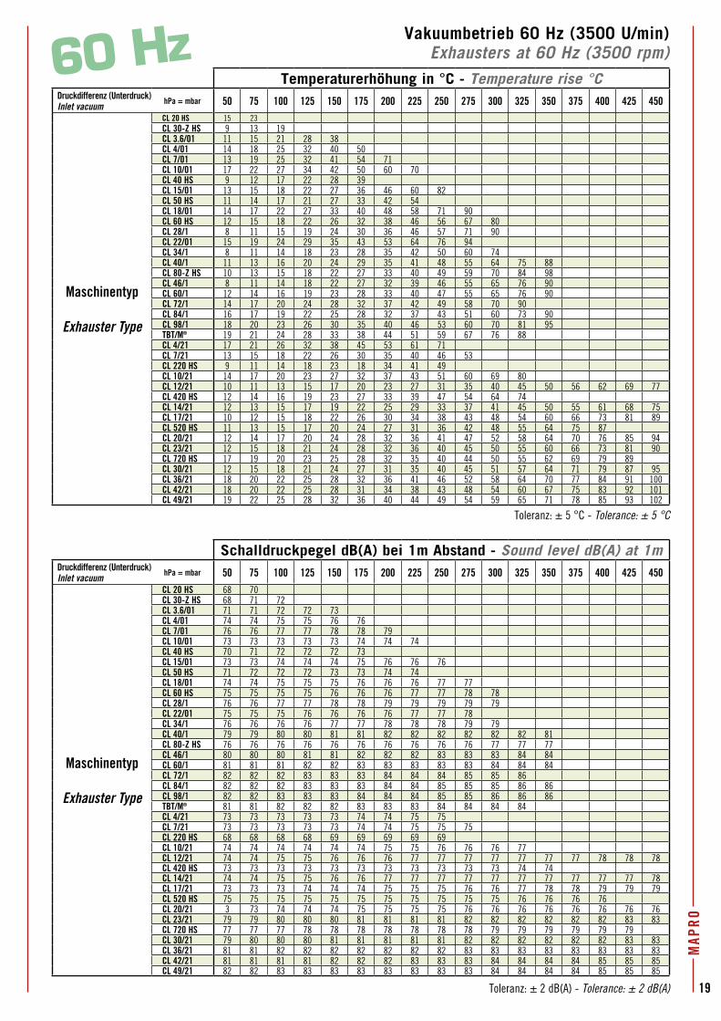
19
MAP
RO
Vakuumbetrieb 60 Hz (3500 U/min)Exhausters at 60 Hz (3500 rpm)60 Hz
Temperaturerhöhung in °C - Temperature rise °CDruckdifferenz (Unterdruck)Inlet vacuum
hPa = mbar 50 75 100 125 150 175 200 225 250 275 300 325 350 375 400 425 450
Maschinentyp
Exhauster Type
CL 20 HS 15 23CL 30-Z HS 9 13 19CL 3.6/01 11 15 21 28 38CL 4/01 14 18 25 32 40 50CL 7/01 13 19 25 32 41 54 71CL 10/01 17 22 27 34 42 50 60 70CL 40 HS 9 12 17 22 28 39CL 15/01 13 15 18 22 27 36 46 60 82CL 50 HS 11 14 17 21 27 33 42 54CL 18/01 14 17 22 27 33 40 48 58 71 90CL 60 HS 12 15 18 22 26 32 38 46 56 67 80CL 28/1 8 11 15 19 24 30 36 46 57 71 90CL 22/01 15 19 24 29 35 43 53 64 76 94CL 34/1 8 11 14 18 23 28 35 42 50 60 74CL 40/1 11 13 16 20 24 29 35 41 48 55 64 75 88CL 80-Z HS 10 13 15 18 22 27 33 40 49 59 70 84 98CL 46/1 8 11 14 18 22 27 32 39 46 55 65 76 90CL 60/1 12 14 16 19 23 28 33 40 47 55 65 76 90CL 72/1 14 17 20 24 28 32 37 42 49 58 70 90CL 84/1 16 17 19 22 25 28 32 37 43 51 60 73 90CL 98/1 18 20 23 26 30 35 40 46 53 60 70 81 95TBT/M® 19 21 24 28 33 38 44 51 59 67 76 88CL 4/21 17 21 26 32 38 45 53 61 71CL 7/21 13 15 18 22 26 30 35 40 46 53CL 220 HS 9 11 14 18 23 18 34 41 49CL 10/21 14 17 20 23 27 32 37 43 51 60 69 80CL 12/21 10 11 13 15 17 20 23 27 31 35 40 45 50 56 62 69 77CL 420 HS 12 14 16 19 23 27 33 39 47 54 64 74CL 14/21 12 13 15 17 19 22 25 29 33 37 41 45 50 55 61 68 75CL 17/21 10 12 15 18 22 26 30 34 38 43 48 54 60 66 73 81 89CL 520 HS 11 13 15 17 20 24 27 31 36 42 48 55 64 75 87CL 20/21 12 14 17 20 24 28 32 36 41 47 52 58 64 70 76 85 94CL 23/21 12 15 18 21 24 28 32 36 40 45 50 55 60 66 73 81 90CL 720 HS 17 19 20 23 25 28 32 35 40 44 50 55 62 69 79 89CL 30/21 12 15 18 21 24 27 31 35 40 45 51 57 64 71 79 87 95CL 36/21 18 20 22 25 28 32 36 41 46 52 58 64 70 77 84 91 100CL 42/21 18 20 22 25 28 31 34 38 43 48 54 60 67 75 83 92 101CL 49/21 19 22 25 28 32 36 40 44 49 54 59 65 71 78 85 93 102
Schalldruckpegel dB(A) bei 1m Abstand - Sound level dB(A) at 1mDruckdifferenz (Unterdruck)Inlet vacuum
hPa = mbar 50 75 100 125 150 175 200 225 250 275 300 325 350 375 400 425 450
Maschinentyp
Exhauster Type
CL 20 HS 68 70CL 30-Z HS 68 71 72CL 3.6/01 71 71 72 72 73CL 4/01 74 74 75 75 76 76CL 7/01 76 76 77 77 78 78 79CL 10/01 73 73 73 73 73 74 74 74CL 40 HS 70 71 72 72 72 73CL 15/01 73 73 74 74 74 75 76 76 76CL 50 HS 71 72 72 72 73 73 74 74CL 18/01 74 74 75 75 75 76 76 76 77 77CL 60 HS 75 75 75 75 76 76 76 77 77 78 78CL 28/1 76 76 77 77 78 78 79 79 79 79 79CL 22/01 75 75 75 76 76 76 76 77 77 78CL 34/1 76 76 76 76 77 77 78 78 78 79 79CL 40/1 79 79 80 80 81 81 82 82 82 82 82 82 81CL 80-Z HS 76 76 76 76 76 76 76 76 76 76 77 77 77CL 46/1 80 80 80 81 81 82 82 82 83 83 83 84 84CL 60/1 81 81 81 82 82 83 83 83 83 83 84 84 84CL 72/1 82 82 82 83 83 83 84 84 84 85 85 86CL 84/1 82 82 82 83 83 83 84 84 85 85 85 86 86CL 98/1 82 82 83 83 83 84 84 84 85 85 86 86 86TBT/M® 81 81 82 82 82 83 83 83 84 84 84 84CL 4/21 73 73 73 73 73 74 74 75 75CL 7/21 73 73 73 73 73 74 74 75 75 75CL 220 HS 68 68 68 68 69 69 69 69 69CL 10/21 74 74 74 74 74 74 75 75 76 76 76 77CL 12/21 74 74 75 75 76 76 76 77 77 77 77 77 77 77 78 78 78CL 420 HS 73 73 73 73 73 73 73 73 73 73 73 74 74CL 14/21 74 74 75 75 76 76 77 77 77 77 77 77 77 77 77 77 78CL 17/21 73 73 73 74 74 74 75 75 75 76 76 77 78 78 79 79 79CL 520 HS 75 75 75 75 75 75 75 75 75 75 75 76 76 76 76CL 20/21 3 73 74 74 74 75 75 75 75 76 76 76 76 76 76 76 76CL 23/21 79 79 80 80 80 81 81 81 81 82 82 82 82 82 82 83 83CL 720 HS 77 77 77 78 78 78 78 78 78 78 79 79 79 79 79 79CL 30/21 79 80 80 80 81 81 81 81 81 82 82 82 82 82 82 83 83CL 36/21 81 81 82 82 82 82 82 82 82 83 83 83 83 83 83 83 83CL 42/21 81 81 81 81 82 82 82 83 83 83 84 84 84 84 85 85 85CL 49/21 82 82 83 83 83 83 83 83 83 83 84 84 84 84 85 85 85
Toleranz: ± 5 °C - Tolerance: ± 5 °C
Toleranz: ± 2 dB(A) - Tolerance: ± 2 dB(A)
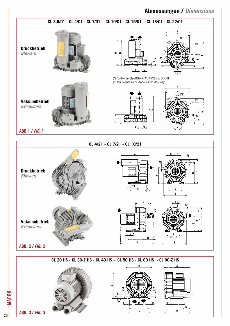
20
MAP
ROAbmessungen / Dimensions
CL 20 HS - CL 30-Z HS - CL 40 HS - CL 50 HS - CL 60 HS - CL 80-Z HS
CL 4/21 - CL 7/21 - CL 10/21
DruckbetriebBlowers
ABB. 2 / FIG. 2
ABB. 3 / FIG. 3
VakuumbetriebExhausters
CL 3.6/01 - CL 4/01 - CL 7/01 - CL 10/01 - CL 15/01 - CL 18/01 - CL 22/01
(*)
(*)
DruckbetriebBlowers
ABB.1 / FIG.1
VakuumbetriebExhausters
(*) Position der Standfüße für CL 3.6/01 und CL 4/01(*) feet position for CL 3.6/01 and CL 4/01 only
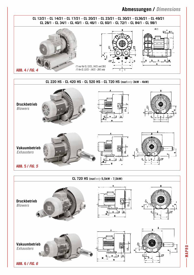
MAP
RO
Abmessungen / Dimensions
CL 720 HS (nur/only 5,5kW - 7,5kW)
DruckbetriebBlowers
VakuumbetriebExhausters
CL 220 HS - CL 420 HS - CL 520 HS - CL 720 HS (nur/only 3kW - 4kW)
DruckbetriebBlowers
VakuumbetriebExhausters
CL 12/21 - CL 14/21 - CL 17/21 - CL 20/21 - CL 23/21 - CL 30/21 - CL36/21 - CL 49/21CL 28/1 - CL 34/1 - CL 40/1 - CL 46/1 - CL 60/1 - CL 72/1 - CL 84/1 - CL 98/1
ABB. 6 / FIG. 6
(*) nur für CL 12/21, 14/21 und 28/1(*) for CL 12/21 - 14/21 - 28/1 onlyABB. 4 / FIG. 4
ABB. 5 / FIG. 5
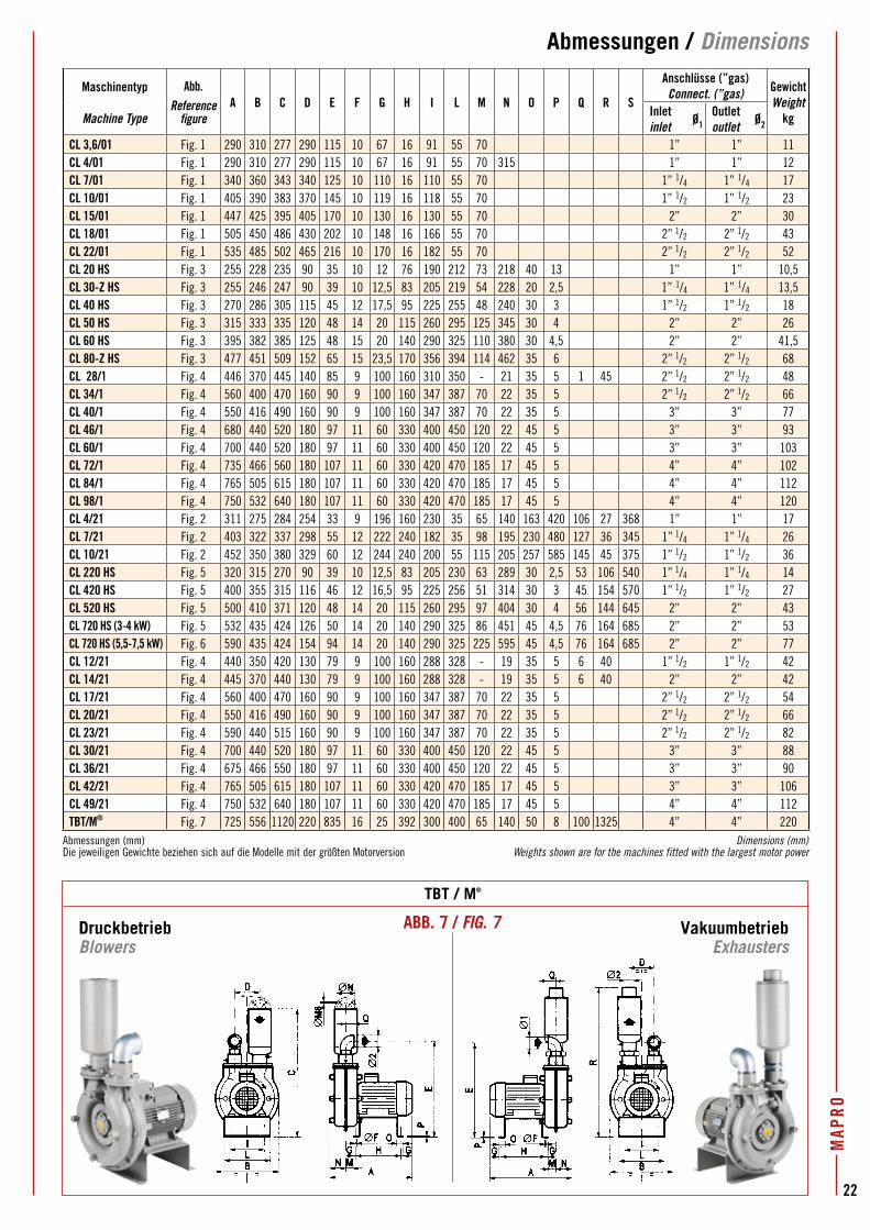
MAP
RO
22
Abmessungen / Dimensions
DruckbetriebBlowers
VakuumbetriebExhausters
Maschinentyp
Machine Type
Abb.Reference
figureA B C D E F G H I L M N O P Q R S
Anschlüsse (”gas)Connect. (”gas) Gewicht
WeightkgInlet
inletØ1
Outletoutlet
Ø2
CL 3,6/01 Fig. 1 290 310 277 290 115 10 67 16 91 55 70 1” 1” 11CL 4/01 Fig. 1 290 310 277 290 115 10 67 16 91 55 70 315 1” 1” 12CL 7/01 Fig. 1 340 360 343 340 125 10 110 16 110 55 70 1” 1/4 1” 1/4 17CL 10/01 Fig. 1 405 390 383 370 145 10 119 16 118 55 70 1” 1/2 1” 1/2 23CL 15/01 Fig. 1 447 425 395 405 170 10 130 16 130 55 70 2” 2” 30CL 18/01 Fig. 1 505 450 486 430 202 10 148 16 166 55 70 2” 1/2 2” 1/2 43CL 22/01 Fig. 1 535 485 502 465 216 10 170 16 182 55 70 2” 1/2 2” 1/2 52CL 20 HS Fig. 3 255 228 235 90 35 10 12 76 190 212 73 218 40 13 1” 1” 10,5CL 30-Z HS Fig. 3 255 246 247 90 39 10 12,5 83 205 219 54 228 20 2,5 1” 1/4 1” 1/4 13,5CL 40 HS Fig. 3 270 286 305 115 45 12 17,5 95 225 255 48 240 30 3 1” 1/2 1” 1/2 18CL 50 HS Fig. 3 315 333 335 120 48 14 20 115 260 295 125 345 30 4 2” 2” 26CL 60 HS Fig. 3 395 382 385 125 48 15 20 140 290 325 110 380 30 4,5 2” 2” 41,5CL 80-Z HS Fig. 3 477 451 509 152 65 15 23,5 170 356 394 114 462 35 6 2” 1/2 2” 1/2 68CL 28/1 Fig. 4 446 370 445 140 85 9 100 160 310 350 - 21 35 5 1 45 2” 1/2 2” 1/2 48CL 34/1 Fig. 4 560 400 470 160 90 9 100 160 347 387 70 22 35 5 2” 1/2 2” 1/2 66CL 40/1 Fig. 4 550 416 490 160 90 9 100 160 347 387 70 22 35 5 3” 3” 77CL 46/1 Fig. 4 680 440 520 180 97 11 60 330 400 450 120 22 45 5 3” 3” 93CL 60/1 Fig. 4 700 440 520 180 97 11 60 330 400 450 120 22 45 5 3” 3” 103CL 72/1 Fig. 4 735 466 560 180 107 11 60 330 420 470 185 17 45 5 4” 4” 102CL 84/1 Fig. 4 765 505 615 180 107 11 60 330 420 470 185 17 45 5 4” 4” 112CL 98/1 Fig. 4 750 532 640 180 107 11 60 330 420 470 185 17 45 5 4” 4” 120CL 4/21 Fig. 2 311 275 284 254 33 9 196 160 230 35 65 140 163 420 106 27 368 1” 1” 17CL 7/21 Fig. 2 403 322 337 298 55 12 222 240 182 35 98 195 230 480 127 36 345 1” 1/4 1” 1/4 26CL 10/21 Fig. 2 452 350 380 329 60 12 244 240 200 55 115 205 257 585 145 45 375 1” 1/2 1” 1/2 36CL 220 HS Fig. 5 320 315 270 90 39 10 12,5 83 205 230 63 289 30 2,5 53 106 540 1” 1/4 1” 1/4 14CL 420 HS Fig. 5 400 355 315 116 46 12 16,5 95 225 256 51 314 30 3 45 154 570 1” 1/2 1” 1/2 27CL 520 HS Fig. 5 500 410 371 120 48 14 20 115 260 295 97 404 30 4 56 144 645 2” 2” 43CL 720 HS (3-4 kW) Fig. 5 532 435 424 126 50 14 20 140 290 325 86 451 45 4,5 76 164 685 2” 2” 53CL 720 HS (5,5-7,5 kW) Fig. 6 590 435 424 154 94 14 20 140 290 325 225 595 45 4,5 76 164 685 2” 2” 77CL 12/21 Fig. 4 440 350 420 130 79 9 100 160 288 328 - 19 35 5 6 40 1” 1/2 1” 1/2 42CL 14/21 Fig. 4 445 370 440 130 79 9 100 160 288 328 - 19 35 5 6 40 2” 2” 42CL 17/21 Fig. 4 560 400 470 160 90 9 100 160 347 387 70 22 35 5 2” 1/2 2” 1/2 54CL 20/21 Fig. 4 550 416 490 160 90 9 100 160 347 387 70 22 35 5 2” 1/2 2” 1/2 66CL 23/21 Fig. 4 590 440 515 160 90 9 100 160 347 387 70 22 35 5 2” 1/2 2” 1/2 82CL 30/21 Fig. 4 700 440 520 180 97 11 60 330 400 450 120 22 45 5 3” 3” 88CL 36/21 Fig. 4 675 466 550 180 97 11 60 330 400 450 120 22 45 5 3” 3” 90CL 42/21 Fig. 4 765 505 615 180 107 11 60 330 420 470 185 17 45 5 3” 3” 106CL 49/21 Fig. 4 750 532 640 180 107 11 60 330 420 470 185 17 45 5 4” 4” 112TBT/M® Fig. 7 725 556 1120 220 835 16 25 392 300 400 65 140 50 8 100 1325 4” 4” 220
Abmessungen (mm)Die jeweiligen Gewichte beziehen sich auf die Modelle mit der größten Motorversion
Dimensions (mm)Weights shown are for the machines fitted with the largest motor power
TBT / M®
ABB. 7 / FIG. 7
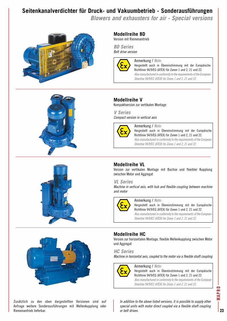
MAP
RO
2323
Seitenkanalverdichter für Druck- und Vakuumbetrieb - SonderausführungenBlowers and exhausters for air - Special versions
Modellreihe BD Version mit Riemenantrieb
BD SeriesBelt drive version
Anmerkung / Note:Hergestellt auch in Übereinstimmung mit der Europäische Richtlinie 94/9/EG (ATEX) für Zonen 1 und 2, 21 und 22.Also manufactured in conformity to the requirements of the European Directive 94/9/EC (ATEX) for Zones 1 and 2, 21 and 22.
Modellreihe VKompaktversion zur vertikalen Montage
V SeriesCompact version in vertical axis
Anmerkung / Note:Hergestellt auch in Übereinstimmung mit der Europäische Richtlinie 94/9/EG (ATEX) für Zonen 1 und 2, 21 und 22.Also manufactured in conformity to the requirements of the European Directive 94/9/EC (ATEX) for Zones 1 and 2, 21 and 22.
Modellreihe VLVersion zur vertikalen Montage mit Buchse und flexibler Kupplung zwischen Motor und Aggregat
VL SeriesMachine in vertical axis, with hub and flexible coupling between machine and motor
Modellreihe HCVersion zur horizontalen Montage, flexible Wellenkupplung zwischen Motor und Aggregat
HC SeriesMachine in horizontal axis, coupled to the motor via a flexible shaft coupling
Zusätzlich zu den oben dargestellten Versionen sind auf Anfrage weitere Sonderausführungen mit Wellenkupplung oder Riemenantrieb lieferbar.
In addition to the above listed versions, it is possible to supply other special units with motor direct coupled via a flexible shaft coupling or belt driven.
Anmerkung / Note:Hergestellt auch in Übereinstimmung mit der Europäische Richtlinie 94/9/EG (ATEX) für Zonen 1 und 2, 21 und 22.Also manufactured in conformity to the requirements of the European Directive 94/9/EC (ATEX) for Zones 1 and 2, 21 and 22.
Anmerkung / Note:Hergestellt auch in Übereinstimmung mit der Europäische Richtlinie 94/9/EG (ATEX) für Zonen 1 und 2, 21 und 22.Also manufactured in conformity to the requirements of the European Directive 94/9/EC (ATEX) for Zones 1 and 2, 21 and 22.
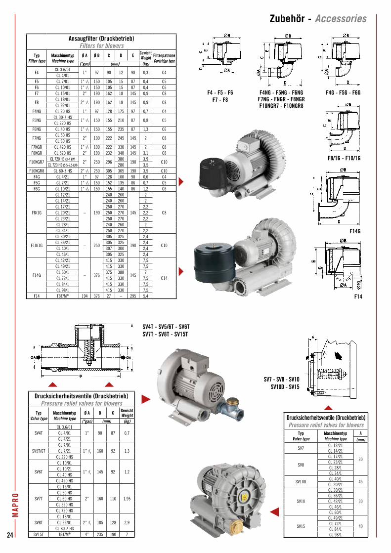
23
Drucksicherheitsventile (Druckbetrieb)Pressure relief valves for blowers
TypValve type
MaschinentypMachine type
A(mm)
SV7CL 12/21
30
CL 14/21
SV8
CL 17/21CL 23/21CL 28/1CL 34/1
SV10DCL 40/1
45CL 20/21
SV10
CL 30/21
30CL 36/21CL 42/21CL 46/1CL 60/1
SV15
CL 49/21
40CL 72/1CL 84/1CL 98/12423
MAP
ROZubehör - Accessories
SV7 - SV8 - SV10SV10D - SV15
SV4T - SV5/6T - SV6TSV7T - SV8T - SV15T
F4 - F5 - F6F7 - F8
F4NG - F5NG - F6NG F7NG - FNGR - F8NGRF10NGR7 - F10NGR8
F4G - F5G - F6G
F8/1G - F10/1G
F14G
F14
Ansaugfilter (Druckbetrieb)Filters for blowers
TypFilter type
MaschinentypMachine type
Ø A Ø B C D E GewichtWeight Filterpatrone
Cartridge type("gas) (mm) (kg)
F4CL 3.6/01
1” 97 90 12 98 0,3 C4CL 4/01
F5 CL 7/01 1” 1/4 150 105 15 87 0,4 C5F6 CL 10/01 1” 1/2 150 105 15 87 0,4 C6F7 CL 15/01 2” 190 162 18 145 0,9 C8
F8CL 18/01
2” 1/2 190 162 18 145 0,9 C8CL 22/01
F4NG CL 20 HS 1” 97 128 175 97 0,7 C4
F5NGCL 30-Z HS
1” 1/4 150 155 210 87 0,8 C5CL 220 HS
F6NG CL 40 HS 1” 1/2 150 155 235 87 1,3 C6
F7NGCL 50 HS
2” 190 222 245 145 2 C8CL 60 HS
F7NGR CL 420 HS 1” 1/2 190 222 330 145 2 C8F8NGR CL 520 HS 2” 190 232 340 145 3,1 C8
F10NGR7CL 720 HS (3-4 kW)
2” 250 296380
1903,9
C10CL 720 HS (5,5-7,5 kW) 280 3,5
F10NGR8 CL 80-Z HS 2” 1/2 250 305 305 190 3,5 C10F4G CL 4/21 1” 97 128 100 98 0,6 C4F5G CL 7/21 1” 1/4 150 152 135 86 0,7 C5F6G CL 10/21 1” 1/2 150 155 140 86 1,2 C6
F8/1G
CL 12/21
– 190
240 260
145
2
C8
CL 14/21 240 260 2CL 17/21 250 270 2,2CL 20/21 250 270 2,2CL 23/21 250 270 2,2CL 28/1 240 260 2CL 34/1 250 270 2,2
F10/1G
CL 30/21
– 250
305 325
190
2,4
C10CL 36/21 305 325 2,4CL 40/1 307 300 2,4CL 46/1 305 325 2,4
F14G
CL 42/21
– 376
415 330
145
7,5
C14
CL 49/21 415 330 7,5CL 60/1 375 388 7CL 72/1 415 330 7,5CL 84/1 415 330 7,5CL 98/1 415 330 7,5
F14 TBT/M® 194 376 27 – 295 5,4
Drucksicherheitsventile (Druckbetrieb)Pressure relief valves for blowers
TypValve type
MaschinentypMachine type
Ø A B C GewichtWeight
("gas) (mm) (kg)
SV4TCL 3.6/01
1” 90 87 0,7CL 4/01CL 4/21
SV5T/6TCL 7/01
1” 1/4 160 92 1,3CL 7/21CL 220 HS
SV6T
CL 10/01
1” 1/2 145 92 1,2CL 10/21CL 40 HS
CL 420 HS
SV7T
CL 15/01
2” 160 110 1,95CL 50 HSCL 60 HS
CL 520 HSCL 720 HS
SV8TCL 18/01
2” 1/2 185 128 2,9CL 22/01CL 80-Z HS
SV15T TBT/M® 4” 235 190 7
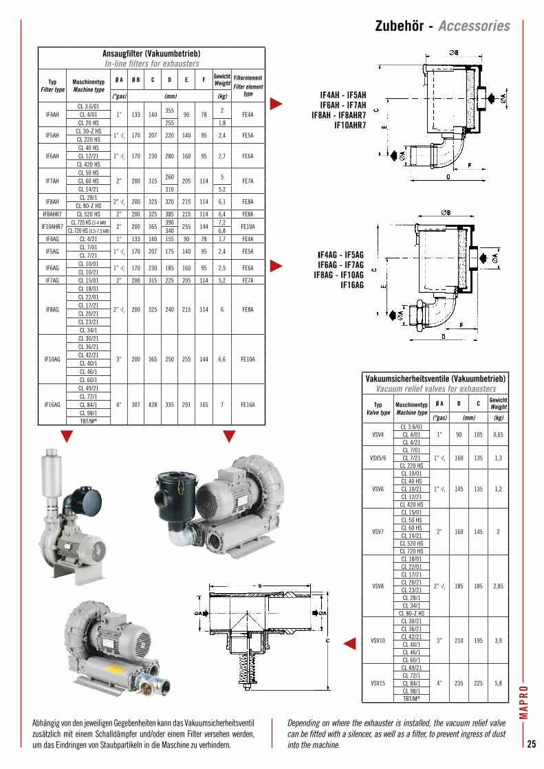
MAP
RO
25
Abhängig von den jeweiligen Gegebenheiten kann das Vakuumsicherheitsventil zusätzlich mit einem Schalldämpfer und/oder einem Filter versehen werden, um das Eindringen von Staubpartikeln in die Maschine zu verhindern.
Depending on where the exhauster is installed, the vacuum relief valve can be fitted with a silencer, as well as a filter, to prevent ingress of dust into the machine.
Zubehör - Accessories
Ansaugfilter (Vakuumbetrieb)In-line filters for exhausters
TypFilter type
MaschinentypMachine type
Ø A Ø B C D E F GewichtWeight
FilterelementFilter element
type("gas) (mm) (kg)
IF4AHCL 3.6/01
1” 133 140355
90 782
FE4ACL 4/01CL 20 HS 255 1,8
IF5AHCL 30-Z HS
1” 1/4 170 207 220 140 95 2,4 FE5ACL 220 HS
IF6AHCL 40 HS
1” 1/2 170 230 280 160 95 2,7 FE6ACL 12/21CL 420 HS
IF7AHCL 50 HS
2” 200 315260
205 1145
FE7ACL 60 HSCL 14/21 310 5,2
IF8AHCL 28/1
2” 1/2 200 325 320 215 114 6,1 FE8ACL 80-Z HS
IF8AHR7 CL 520 HS 2” 200 325 385 215 114 6,4 FE8A
IF10AHR7CL 720 HS (3-4 kW)
2” 200 365390
255 1447,2
FE10ACL 720 HS (5,5-7,5 kW) 340 6,8
IF4AG CL 4/21 1” 133 140 155 90 78 1,7 FE4A
IF5AGCL 7/01
1” 1/4 170 207 175 140 95 2,4 FE5ACL 7/21
IF6AGCL 10/01
1” 1/2 170 230 185 160 95 2,5 FE6ACL 10/21
IF7AG CL 15/01 2” 200 315 225 205 114 5,2 FE7A
IF8AG
CL 18/01
2” 1/2 200 325 240 215 114 6 FE8A
CL 22/01CL 17/21CL 20/21CL 23/21CL 34/1
IF10AG
CL 30/21
3” 200 365 250 255 144 6,6 FE10A
CL 36/21CL 42/21CL 40/1CL 46/1CL 60/1
IF16AG
CL 49/21
4” 307 428 335 291 165 7 FE16ACL 72/1CL 84/1CL 98/1TBT/M®
Vakuumsicherheitsventile (Vakuumbetrieb)Vacuum relief valves for exhausters
TypValve type
MaschinentypMachine type
Ø A B C GewichtWeight
("gas) (mm) (kg)
VSV4CL 3.6/01
1” 90 105 0,65CL 4/01CL 4/21
VSV5/6CL 7/01
1” 1/4 160 135 1,3CL 7/21CL 220 HS
VSV6
CL 10/01
1” 1/2 145 135 1,2CL 40 HSCL 10/21CL 12/21
CL 420 HS
VSV7
CL 15/01
2” 160 145 2
CL 50 HSCL 60 HSCL 14/21
CL 520 HSCL 720 HS
VSV8
CL 18/01
2” 1/2 185 185 2,85
CL 22/01CL 17/21CL 20/21CL 23/21CL 28/1CL 34/1
CL 80-Z HS
VSV10
CL 30/21
3” 210 195 3,9
CL 36/21CL 42/21CL 40/1CL 46/1CL 60/1
VSV15
CL 49/21
4” 235 225 5,8CL 72/1CL 84/1CL 98/1TBT/M®
IF4AH - IF5AHIF6AH - IF7AH
IF8AH - IF8AHR7IF10AHR7
IF4AG - IF5AGIF6AG - IF7AG
IF8AG - IF10AGIF16AG
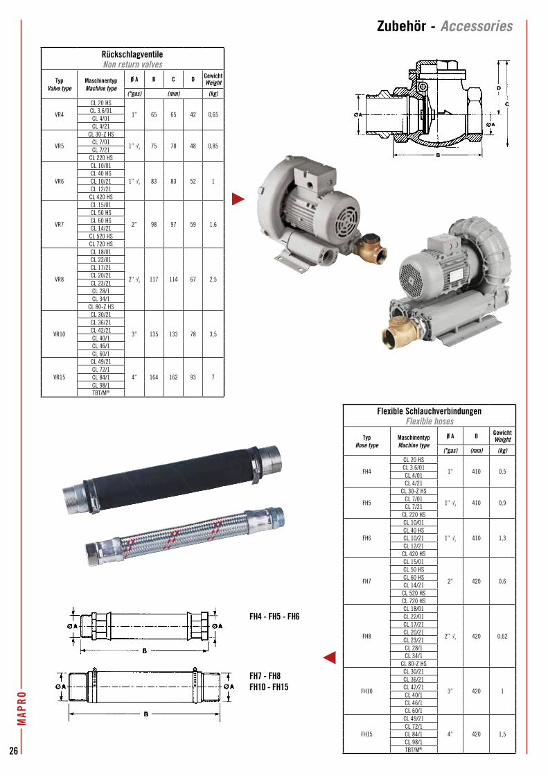
26
MAP
RO
FH4 - FH5 - FH6
FH7 - FH8FH10 - FH15
Zubehör - Accessories
RückschlagventileNon return valves
TypValve type
MaschinentypMachine type
Ø A B C D GewichtWeight
("gas) (mm) (kg)
VR4
CL 20 HS
1” 65 65 42 0,65CL 3.6/01CL 4/01CL 4/21
VR5
CL 30-Z HS
1” 1/4 75 78 48 0,85CL 7/01CL 7/21
CL 220 HS
VR6
CL 10/01
1” 1/2 83 83 52 1CL 40 HSCL 10/21CL 12/21
CL 420 HS
VR7
CL 15/01
2” 98 97 59 1,6
CL 50 HSCL 60 HSCL 14/21
CL 520 HSCL 720 HS
VR8
CL 18/01
2” 1/2 117 114 67 2,5
CL 22/01CL 17/21CL 20/21CL 23/21CL 28/1CL 34/1
CL 80-Z HS
VR10
CL 30/21
3” 135 133 78 3,5
CL 36/21CL 42/21CL 40/1CL 46/1CL 60/1
VR15
CL 49/21
4” 164 162 93 7CL 72/1CL 84/1CL 98/1TBT/M®
Flexible SchlauchverbindungenFlexible hoses
TypHose type
MaschinentypMachine type
Ø A B GewichtWeight
("gas) (mm) (kg)
FH4
CL 20 HS
1” 410 0,5CL 3.6/01CL 4/01CL 4/21
FH5
CL 30-Z HS
1” 1/4 410 0,9CL 7/01CL 7/21
CL 220 HS
FH6
CL 10/01
1” 1/2 410 1,3CL 40 HSCL 10/21CL 12/21
CL 420 HS
FH7
CL 15/01
2” 420 0,6
CL 50 HSCL 60 HSCL 14/21
CL 520 HSCL 720 HS
FH8
CL 18/01
2” 1/2 420 0,62
CL 22/01CL 17/21CL 20/21CL 23/21CL 28/1CL 34/1
CL 80-Z HS
FH10
CL 30/21
3” 420 1
CL 36/21CL 42/21CL 40/1CL 46/1CL 60/1
FH15
CL 49/21
4” 420 1,5CL 72/1CL 84/1CL 98/1TBT/M®
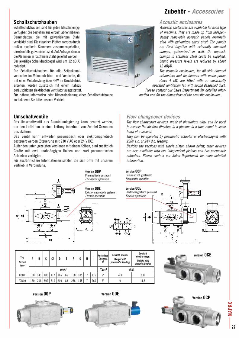
MAP
RO
27
Zubehör - Accessories
Typ
Device type
A B C C1 D E F G H IAnschlussConnect.
Ø
Gewicht pneum.Weight with
pneumatic feeding
Gewichtelektro-magn.
Weight with electric feeding
(mm) ("gas) (kg)
FCD7 100 143 403 417 165 66 168 105 7 175 2" 4,3 6,8
FCD10 150 206 502 516 219 88 256 155 7 266 3" 9 11,5
SchallschutzhaubenSchallschutzhauben sind für jeden Maschinentyp verfügbar. Sie bestehen aus einzeln abnehmbaren Dämmplatten, die mit galvanisiertem Stahl verkleidet sind. Die einzelnen Platten werden durch außen montierte Klammern zusammengehalten, die ebenfalls galvanisiert sind. Auf Anfrage können die Klemmen in rostfreiem Stahl geliefert werden.Der jeweilige Schalldruckpegel wird um 12 dB(A) reduziert. Die Schallschutzhauben für alle Seitenkanal-verdichter im Vakuumbetrieb und Verdichte, die mit einer Motorleistung über 4kW im Druckbetrieb arbeiten, werden zusätzlich mit einem nahezu geräuschlosen elektrischen Ventilator ausgestattet. Für nähere Information oder Dimensionierung einer Schallschutzhaube kontaktieren Sie bitte unseren Vertrieb.
UmschaltventileDas Umschaltventil aus Aluminiumlegierung kann benutzt werden, um den Luftstrom in einer Leitung innerhalb von Zehntel-Sekunden umzukehren.Das Ventil kann entweder pneumatisch oder elektromagnetisch gesteuert werden (Steuerung mit 230 V AC oder 24 V DC).Außer den unten gezeigten Versionen mit einem Kolben, sind zusätzlich Geräte mit zwei unabhängigen Kolben und zwei pneumatischen Antrieben verfügbar. Für ausführlichere Informationen setzten Sie sich bitte mit unserem Vertrieb in Verbindung.
Acoustic enclosuresAcoustic enclosures are available for each type of machine. They are made up from indepen-dently removable acoustic panels externally clad with galvanized sheet steel. The panels are fixed together with externally mounted clamps, galvanized as well. On request, clamps in stainless steel could be supplied. Sound pressure levels are reduced by about 12 dB(A). The acoustic enclosures, for all side channel exhausters and for blowers with motor power above 4 kW, are fitted with an electrically
operated ventilation fan with sound deadened duct. Please contact our Sales Department for detailed infor-
mation and for the dimensions of the acoustic enclosures.
Flow changeover devicesThe flow changeover devices, made of aluminium alloy, can be used to reverse the air flow direction in a pipeline in a time round to some tenth of a second. They can be operated by pneumatic actuator or electromagnet with 230V a.c. or 24V d.c. feeding.Besides the versions with single piston shown below, other devices are also available with two independent pistons and two pneumatic actuators. Please contact our Sales Department for more detailed information.
Version OOP Version OOEVersion OCP
Version OCE
Version OOPPneumatisch gesteuertPneumatic operation
Version OOEElektro-magnetisch gesteuertElectric operation
Version OCPPneumatisch gesteuertPneumatic operation
Version OCEElektro-magnetisch gesteuertElectric operation
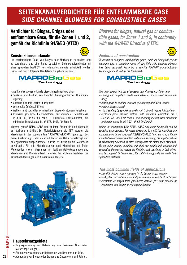
28
MAP
RO
SEITENKANALVERDICHTER FÜR ENTFLAMMBARE GASESIDE CHANNEL BLOWERS FOR COMBUSTIBLE GASES
Verdichter für Biogas, Erdgas oder entflammbare Gase, für die Zonen 1 und 2, gemäß der Richtlinie 94/9/EG (ATEX)
KonstruktionsmerkmaleUm entflammbare Gase, wie Biogas oder Methangas zu fördern oder zu verdichten, sind eine Reihe gasdichter Seitenkanalverdichter mit einer speziellen MAPRO® Herstellungstechnologie entwickelt worden. Diese sind durch folgende Handelsmarke gekennzeichnet:
Haupteinsatzgebiete• Biogasgewinnung zur Befeuerung von Brennern, Öfen oder
Motoreinspeisungen;• Fäulnisgasgewinnung zur Befeuerung von Brennern und Öfen;• Absaugung von Biogas oder Erdgas aus Gasometern und Rohren.
Hauptkonstruktionsmerkmale dieses Maschinentyps sind:• Gehäuse und Laufrad aus komplett funkengeschützter Aluminium-
legierung;• Gehäuse sind mit Loctite imprägniert;• versiegelte Gehäusehälften;• Welle ist mit speziellen schmierfreien Lippendichtungen versehen;• Explosionsgeschütze Elektromotoren, mit minimaler Schutzklasse
Ex-d IIB T3, IP 55, für Zone 1; Funkenfreie Elektromotoren, mit minimaler Schutzklasse Ex-nA IIT3, IP 65, für Zone 2.
Motoren gemäß NEMA, SABS und anderen Standards sind ebenfalls auf Anfrage erhältlich. Bei Motorleistungen bis 4kW werden die Maschinen in der sogenannten “KOMPAKT-VERSION” gefertigt. Bei dieser Ausführung ist der Motor mit Bolzen am Gehäuse befestigt und das dynamisch ausgewuchtete Laufrad ist direkt an die Motorwelle angebracht. Für alle Motorleistungen sind Maschinen mit freien Wellenenden, sowie Maschinen mit flexiblen Wellenkupplungen und Maschinen mit Riemenantrieb lieferbar. Bei letzteren bestehen die Antriebsabdeckungen aus funkenfreiem Material.
Blowers for biogas, natural gas or combus- tible gases, for Zones 1 and 2, in conformity with the 94/9/EC Directive (ATEX)
Features of constructionTo extract or compress combustible gases, such as biological gas or methane gas, a complete range of gas-tight side channel blowers has been designed, featuring a specific MAPRO® manufacturing technology, identified by the trademark:
The main characteristics of construction of these machines are:• casing and impellers made completely of spark proof aluminium
alloy;• static parts in contact with the gas impregnated with Loctite;• casing halves sealed;• shaft sealing by special lip seals which do not require lubrication;• explosion-proof electric motors, with minimum protection class
Ex-d IIB T3 - IP 55 for Zone 1; non-sparking motors, with maximum protection class Ex-nA II T3 - IP 65 for Zone 2.
Motors in accordance with NEMA, SABS and other Standards can be supplied upon request. For motor powers up to 4 kW, the machines are manufactured in the so-called “CLOSE COUPLED” version - i.e., a flange mounted electric motor is bolted to the mahine casing; the impeller, which is dynamically balanced, is fitted directly onto the motor shaft extension. For all motor powers, machines with their own shafts and bearings and coupled to the electric motors via flexible shaft couplings or belt drives, can be supplied. In these cases, the safety drive guards are made from spark-free material.
The most common fields of applications• Landfill biogas recovery to feed torch, burner or gas engine;• tank, plant or contaminated soil gas recovery to feed torch or burner;• extraction of biogas from gasometer, natural gas from pipeline or
gasometer and burner or gas engine feeding.
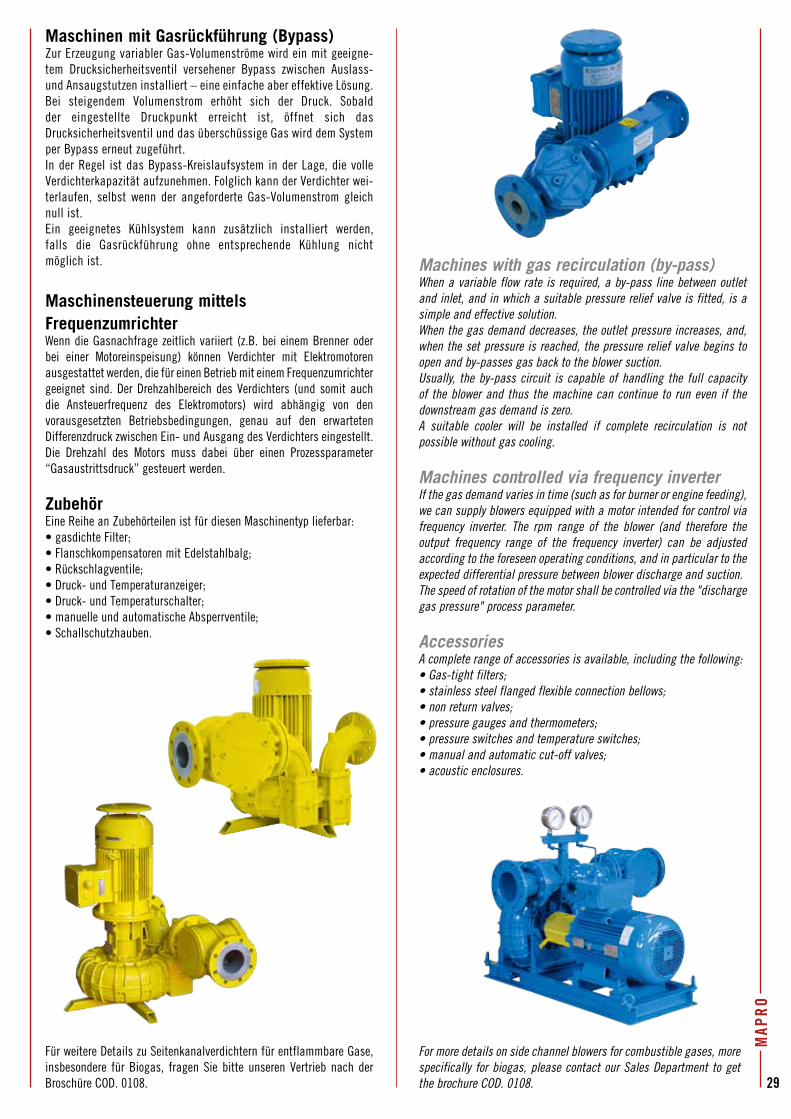
MAP
RO
29
Maschinen mit Gasrückführung (Bypass)Zur Erzeugung variabler Gas-Volumenströme wird ein mit geeigne-tem Drucksicherheitsventil versehener Bypass zwischen Auslass-und Ansaugstutzen installiert – eine einfache aber effektive Lösung.Bei steigendem Volumenstrom erhöht sich der Druck. Sobald der eingestellte Druckpunkt erreicht ist, öffnet sich das Drucksicherheitsventil und das überschüssige Gas wird dem System per Bypass erneut zugeführt. In der Regel ist das Bypass-Kreislaufsystem in der Lage, die volle Verdichterkapazität aufzunehmen. Folglich kann der Verdichter wei-terlaufen, selbst wenn der angeforderte Gas-Volumenstrom gleich null ist. Ein geeignetes Kühlsystem kann zusätzlich installiert werden, falls die Gasrückführung ohne entsprechende Kühlung nicht möglich ist.
Maschinensteuerung mittels FrequenzumrichterWenn die Gasnachfrage zeitlich variiert (z.B. bei einem Brenner oder bei einer Motoreinspeisung) können Verdichter mit Elektromotoren ausgestattet werden, die für einen Betrieb mit einem Frequenzumrichter geeignet sind. Der Drehzahlbereich des Verdichters (und somit auch die Ansteuerfrequenz des Elektromotors) wird abhängig von den vorausgesetzten Betriebsbedingungen, genau auf den erwarteten Differenzdruck zwischen Ein- und Ausgang des Verdichters eingestellt.Die Drehzahl des Motors muss dabei über einen Prozessparameter “Gasaustrittsdruck” gesteuert werden.
ZubehörEine Reihe an Zubehörteilen ist für diesen Maschinentyp lieferbar:• gasdichte Filter;• Flanschkompensatoren mit Edelstahlbalg;• Rückschlagventile;• Druck- und Temperaturanzeiger;• Druck- und Temperaturschalter;• manuelle und automatische Absperrventile;• Schallschutzhauben.
Für weitere Details zu Seitenkanalverdichtern für entflammbare Gase, insbesondere für Biogas, fragen Sie bitte unseren Vertrieb nach der Broschüre COD. 0108.
Machines with gas recirculation (by-pass)When a variable flow rate is required, a by-pass line between outlet and inlet, and in which a suitable pressure relief valve is fitted, is a simple and effective solution.When the gas demand decreases, the outlet pressure increases, and, when the set pressure is reached, the pressure relief valve begins to open and by-passes gas back to the blower suction.Usually, the by-pass circuit is capable of handling the full capacity of the blower and thus the machine can continue to run even if the downstream gas demand is zero.A suitable cooler will be installed if complete recirculation is not possible without gas cooling.
Machines controlled via frequency inverterIf the gas demand varies in time (such as for burner or engine feeding), we can supply blowers equipped with a motor intended for control via frequency inverter. The rpm range of the blower (and therefore the output frequency range of the frequency inverter) can be adjusted according to the foreseen operating conditions, and in particular to the expected differential pressure between blower discharge and suction.The speed of rotation of the motor shall be controlled via the "discharge gas pressure" process parameter.
AccessoriesA complete range of accessories is available, including the following:• Gas-tight filters;• stainless steel flanged flexible connection bellows;• non return valves;• pressure gauges and thermometers;• pressure switches and temperature switches;• manual and automatic cut-off valves;• acoustic enclosures.
For more details on side channel blowers for combustible gases, more specifically for biogas, please contact our Sales Department to get the brochure COD. 0108.
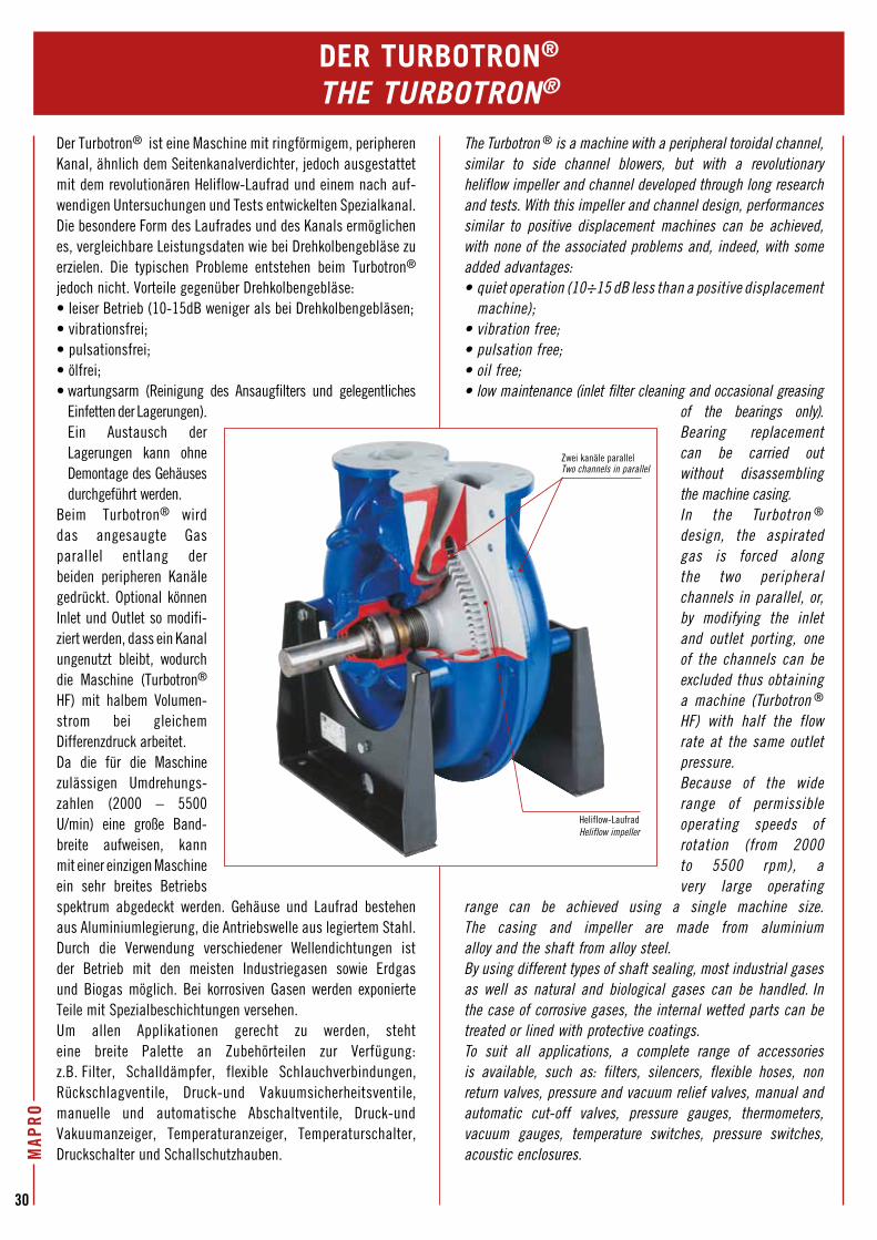
30
MAP
RO
The Turbotron ® is a machine with a peripheral toroidal channel, similar to side channel blowers, but with a revolutionary heliflow impeller and channel developed through long research and tests. With this impeller and channel design, performances similar to positive displacement machines can be achieved, with none of the associated problems and, indeed, with some added advantages:• quiet operation (10÷15 dB less than a positive displacement
machine);• vibration free;• pulsation free;• oil free;• low maintenance (inlet filter cleaning and occasional greasing
of the bearings only). Bearing replacement can be carried out without dis as sembling the machine casing.In the Turbotron ® design, the aspirated gas is forced along the two peripheral channels in parallel, or, by modifying the inlet and outlet porting, one of the channels can be excluded thus obtaining a machine (Turbotron ® HF) with half the flow rate at the same outlet pressure. Because of the wide range of permissible operating speeds of rotation (from 2000 to 5500 rpm), a very large operating
range can be achieved using a single machine size. The casing and impeller are made from aluminium alloy and the shaft from alloy steel. By using different types of shaft sealing, most industrial gases as well as natural and biological gases can be handled. In the case of corrosive gases, the internal wetted parts can be treated or lined with protective coatings. To suit all applications, a complete range of accessories is available, such as: filters, silencers, flexible hoses, non return valves, pressure and vacuum relief valves, manual and automatic cut-off valves, pressure gauges, thermometers, vacuum gauges, temperature switches, pressure switches, acoustic enclosures.
Der Turbotron® ist eine Maschine mit ringförmigem, peripheren Kanal, ähnlich dem Seitenkanalverdichter, jedoch ausgestattet mit dem revolutionären Heliflow-Laufrad und einem nach auf-wendigen Untersuchungen und Tests entwickelten Spezialkanal. Die besondere Form des Laufrades und des Kanals ermöglichen es, vergleichbare Leistungsdaten wie bei Drehkolbengebläse zu erzielen. Die typischen Probleme entstehen beim Turbotron® jedoch nicht. Vorteile gegenüber Drehkolbengebläse: • leiser Betrieb (10-15dB weniger als bei Drehkolbengebläsen; • vibrationsfrei;• pulsationsfrei;• ölfrei;• wartungsarm (Reinigung des Ansaugfilters und gelegentliches
Einfetten der Lagerungen). Ein Austausch der Lagerungen kann ohne Demontage des Gehäuses durchgeführt werden.
Beim Turbotron® wird das angesaugte Gas parallel entlang der beiden peripheren Kanäle gedrückt. Optional können Inlet und Outlet so modifi-ziert werden, dass ein Kanal ungenutzt bleibt, wodurch die Maschine (Turbotron® HF) mit halbem Volumen-strom bei gleichem Differenzdruck arbeitet. Da die für die Maschine zulässigen Umdrehungs-zahlen (2000 – 5500 U/min) eine große Band-breite aufweisen, kann mit einer einzigen Maschine ein sehr breites Betriebs spektrum abgedeckt werden. Gehäuse und Laufrad bestehen aus Aluminiumlegierung, die Antriebswelle aus legiertem Stahl. Durch die Verwendung verschiedener Wellendichtungen ist der Betrieb mit den meisten Industriegasen sowie Erdgas und Biogas möglich. Bei korrosiven Gasen werden exponierte Teile mit Spezialbeschichtungen versehen. Um allen Applikationen gerecht zu werden, steht eine breite Palette an Zubehörteilen zur Verfügung: z.B. Filter, Schalldämpfer, flexible Schlauchverbindungen, Rückschlagventile, Druck-und Vakuumsicherheitsventile, manuelle und automatische Abschaltventile, Druck-und Vakuumanzeiger, Temperaturanzeiger, Temperaturschalter, Druckschalter und Schallschutzhauben.
DER TURBOTRON®
THE TURBOTRON®
Zwei kanäle parallelTwo channels in parallel
Heliflow-LaufradHeliflow impeller
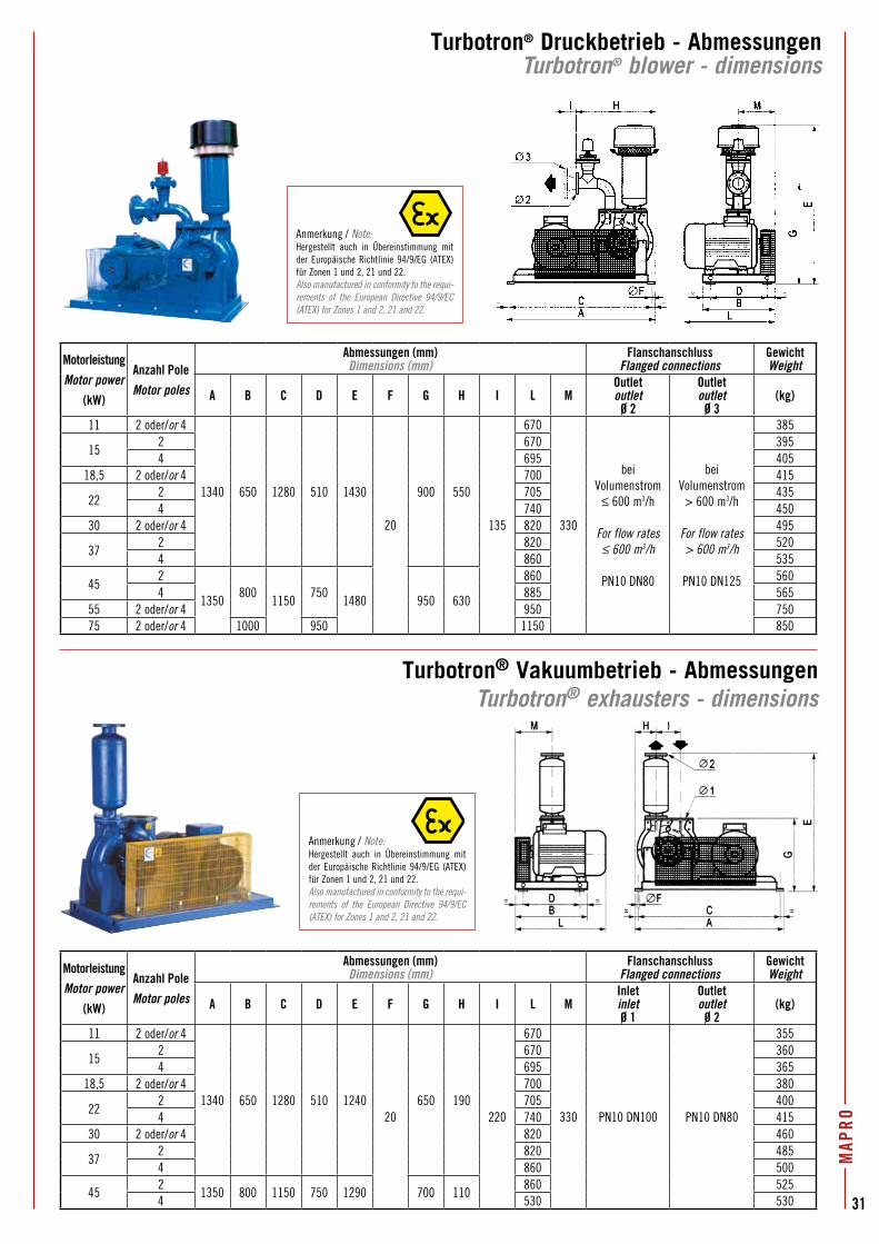
MAP
RO
31
Turbotron® Druckbetrieb - AbmessungenTurbotron® blower - dimensions
Turbotron® Vakuumbetrieb - AbmessungenTurbotron® exhausters - dimensions
Motorleistung
Motor power
(kW)
Anzahl Pole
Motor poles
Abmessungen (mm)Dimensions (mm)
FlanschanschlussFlanged connections
GewichtWeight
A B C D E F G H I L MOutletoutlet
Ø 2
Outletoutlet
Ø 3(kg)
11 2 oder/or 4
1340 650 1280 510 1430
20
900 550
135
670
330
bei Volumenstrom
≤ 600 m3/h
For flow rates≤ 600 m3/h
PN10 DN80
bei Volumenstrom
> 600 m3/h
For flow rates> 600 m3/h
PN10 DN125
385
152 670 3954 695 405
18,5 2 oder/or 4 700 415
222 705 4354 740 450
30 2 oder/or 4 820 495
372 820 5204 860 535
452
1350800
1150750
1480 950 630
860 5604 885 565
55 2 oder/or 4 950 75075 2 oder/or 4 1000 950 1150 850
Motorleistung
Motor power
(kW)
Anzahl Pole
Motor poles
Abmessungen (mm)Dimensions (mm)
FlanschanschlussFlanged connections
GewichtWeight
A B C D E F G H I L MInletinlet Ø 1
Outletoutlet
Ø 2(kg)
11 2 oder/or 4
1340 650 1280 510 124020
650 190220
670
330 PN10 DN100 PN10 DN80
355
152 670 3604 695 365
18,5 2 oder/or 4 700 380
222 705 4004 740 415
30 2 oder/or 4 820 460
372 820 4854 860 500
452
1350 800 1150 750 1290 700 110860 525
4 530 530
Anmerkung / Note:Hergestellt auch in Übereinstimmung mit der Europäische Richtlinie 94/9/EG (ATEX) für Zonen 1 und 2, 21 und 22.Also manufactured in conformity to the requi-rements of the European Directive 94/9/EC (ATEX) for Zones 1 and 2, 21 and 22.
Anmerkung / Note:Hergestellt auch in Übereinstimmung mit der Europäische Richtlinie 94/9/EG (ATEX) für Zonen 1 und 2, 21 und 22.Also manufactured in conformity to the requi-rements of the European Directive 94/9/EC (ATEX) for Zones 1 and 2, 21 and 22.
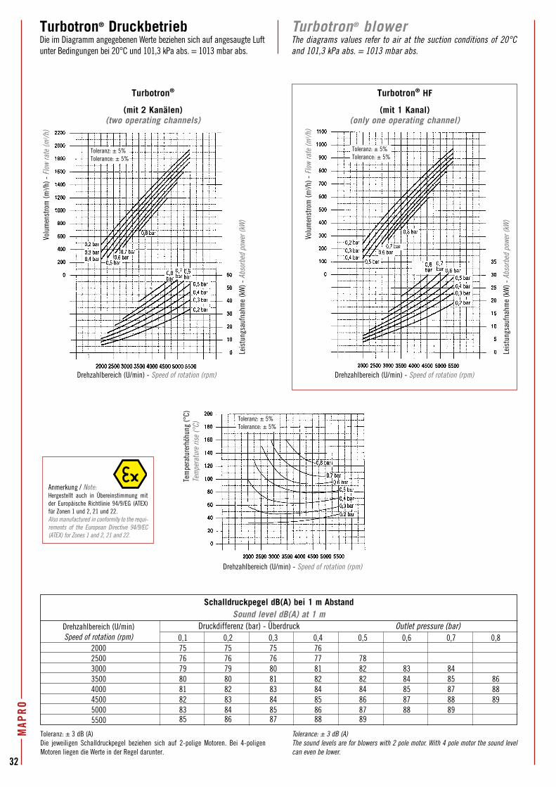
32
MAP
ROTurbotron® blowerThe diagrams values refer to air at the suction conditions of 20°C and 101,3 kPa abs. = 1013 mbar abs.
Turbotron® DruckbetriebDie im Diagramm angegebenen Werte beziehen sich auf angesaugte Luft unter Bedingungen bei 20°C und 101,3 kPa abs. = 1013 mbar abs.
Schalldruckpegel dB(A) bei 1 m AbstandSound level dB(A) at 1 m
Drehzahlbereich (U/min) Speed of rotation (rpm) 0,1 0,2 0,3 0,4 0,5 0,6 0,7 0,8 2000 75 75 75 76 2500 76 76 76 77 78 3000 79 79 80 81 82 83 84 3500 80 80 81 82 82 84 85 86 4000 81 82 83 84 84 85 87 88 4500 82 83 84 85 86 87 88 89 5000 83 84 85 86 87 88 89 5500 85 86 87 88 89
Druckdifferenz (bar) - Überdruck Outlet pressure (bar)
Toleranz: ± 3 dB (A)Die jeweiligen Schalldruckpegel beziehen sich auf 2-polige Motoren. Bei 4-poligen Motoren liegen die Werte in der Regel darunter.
Tolerance: ± 3 dB (A)The sound levels are for blowers with 2 pole motor. With 4 pole motor the sound level can even be lower.
Anmerkung / Note:Hergestellt auch in Übereinstimmung mit der Europäische Richtlinie 94/9/EG (ATEX) für Zonen 1 und 2, 21 und 22.Also manufactured in conformity to the requi-rements of the European Directive 94/9/EC (ATEX) for Zones 1 and 2, 21 and 22.
Tem
pera
ture
rhöh
ung
(°C)
Tem
pera
ture
rise
(°C)
Toleranz: ± 5%Tolerance: ± 5%
Toleranz: ± 5%Tolerance: ± 5%
Toleranz: ± 5%Tolerance: ± 5%
Drehzahlbereich (U/min) - Speed of rotation (rpm)
Turbotron® HF
(mit 1 Kanal)(only one operating channel)
Drehzahlbereich (U/min) - Speed of rotation (rpm)Drehzahlbereich (U/min) - Speed of rotation (rpm)
Turbotron®
(mit 2 Kanälen)(two operating channels)
Volu
men
stro
m (m
3 /h) -
Flo
w ra
te (m
3 /h)
Volu
men
stro
m (m
3 /h) -
Flo
w ra
te (m
3 /h)
Leis
tung
sauf
nahm
e (k
W) -
Abs
orbe
d po
wer (
kW)
Leis
tung
sauf
nahm
e (k
W) -
Abs
orbe
d po
wer (
kW)
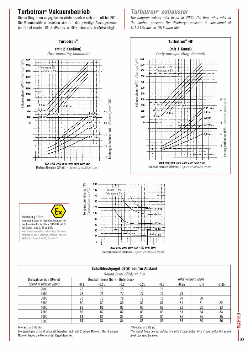
MAP
RO
33
Anmerkung / Note:Hergestellt auch in Übereinstimmung mit der Europäische Richtlinie 94/9/EG (ATEX) für Zonen 1 und 2, 21 und 22.Also manufactured in conformity to the requi-rements of the European Directive 94/9/EC (ATEX) for Zones 1 and 2, 21 and 22.
Schalldruckpegel dB(A) bei 1m AbstandSound level dB(A) at 1 m
Drehzahlbereich (U/min) Speed of rotation (rpm) -0,1 -0,15 -0,2 -0,25 -0,3 -0,35 -0,4 -0,45 2000 75 75 75 76 76 2500 76 76 77 77 77 78 3000 78 78 78 79 79 79 80 3500 80 80 80 81 81 81 81 82 4000 81 81 81 82 82 82 82 83 4500 82 82 82 83 83 83 84 84 5000 84 84 84 84 84 85 85 85 5500 84 84 84 85 85 85 86 86
Toleranz: ± 3 dB (A)Die jeweiligen Schalldruckpegel beziehen sich auf 2-polige Motoren. Bei 4-poligen Motoren liegen die Werte in der Regel darunter.
Tolerance: ± 3 dB (A)The sound levels are for exhausters with 2 pole motor. With 4 pole motor the sound level can even be lower.
Turbotron® exhausterThe diagram values refer to air at 20°C. The flow rates refer to the suction pressure. The discharge pressure is considered at 101,3 kPa abs. = 1013 mbar abs.
Turbotron® VakuumbetriebDie im Diagramm angegebenen Werte beziehen sich auf Luft bei 20°C. Die Volumenströme beziehen sich auf das jeweilige Ansaugvakuum. Am Outlet wurden 101,3 kPa abs. = 1013 mbar abs. berücksichtigt.
Turbotron® HF
(mit 1 Kanal)(only one operating channel)
Turbotron®
(mit 2 Kanälen)(two operating channels)
Toleranz: ± 5%Tolerance: ± 5%
Toleranz: ± 5%Tolerance: ± 5%
Toleranz: ± 5%Tolerance: ± 5%
Druckdifferenz (bar) - Unterdruck Inlet vacuum (bar)
Tem
pera
ture
rhöh
ung
(°C)
Tem
pera
ture
rise
(°C)
Drehzahlbereich (U/min) - Speed of rotation (rpm)
Drehzahlbereich (U/min) - Speed of rotation (rpm)Drehzahlbereich (U/min) - Speed of rotation (rpm)
Volu
men
stro
m (m
3 /h) -
Flo
w ra
te (m
3 /h)
Volu
men
stro
m (m
3 /h) -
Flo
w ra
te (m
3 /h)
Leis
tung
sauf
nahm
e (k
W) -
Abs
orbe
d po
wer (
kW)
Leis
tung
sauf
nahm
e (k
W) -
Abs
orbe
d po
wer (
kW)
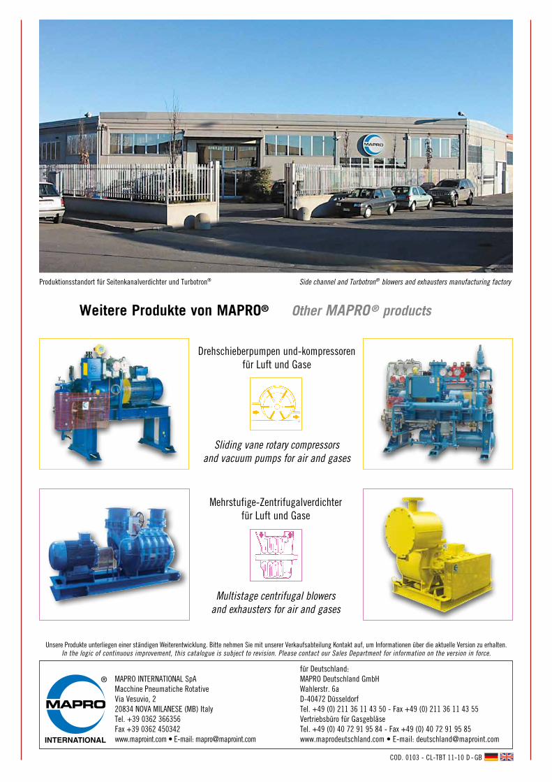
Weitere Produkte von MAPRO® Other MAPRO® products
Unsere Produkte unterliegen einer ständigen Weiterentwicklung. Bitte nehmen Sie mit unserer Verkaufsabteilung Kontakt auf, um Informationen über die aktuelle Version zu erhalten.In the logic of continuous improvement, this catalogue is subject to revision. Please contact our Sales Department for information on the version in force.
Produktionsstandort für Seitenkanalverdichter und Turbotron® Side channel and Turbotron® blowers and exhausters manufacturing factory
COD. 0103 - CL-TBT 11-10 D - GB
Drehschieberpumpen und-kompressoren für Luft und Gase
Sliding vane rotary compressors and vacuum pumps for air and gases
Mehrstufige-Zentrifugalverdichterfür Luft und Gase
Multistage centrifugal blowers and exhausters for air and gases
für Deutschland:MAPRO Deutschland GmbHWahlerstr. 6aD-40472 DüsseldorfTel. +49 (0) 211 36 11 43 50 - Fax +49 (0) 211 36 11 43 55Vertriebsbüro für GasgebläseTel. +49 (0) 40 72 91 95 84 - Fax +49 (0) 40 72 91 95 85www.maprodeutschland.com • E-mail: [email protected]
® MAPRO INTERNATIONAL SpAMacchine Pneumatiche RotativeVia Vesuvio, 220834 NOVA MILANESE (MB) ItalyTel. +39 0362 366356Fax +39 0362 450342www.maproint.com • E-mail: [email protected]