Embed Size (px)
Citation preview

2015
CUTTING TOOLS FROM SANDVIK COROMANT
Turning toolsGENERAL TURNING
PARTING AND GROOVINGTHREAD TURNING
MULTIFUNCTIONAL TOOLSTOOL HOLDING
TURNING TOOL ADAPTORS

I 1
ISO 13399 GENERAL INFORMATION
EN
G T
UR
N
A
B
C
D
E
F
G
H
I
GENERAL INFORMATION ISO 13399
To make life easier, a new standard has been developed
ISO 13399 is an international standard that strives to simplify the exchange of data for cutting tools. You will notice a slight difference through the new parameters and descriptions of each tool.
For the first time ever, there is a standardized way of describing product data regarding cutting tools. When all tools in the industry share the same parameters and definitions, communicating tool information becomes very straightforward.
What does this mean to you?
Basically, it means that your systems can talk to ours, as they all speak the same language. Download product data from our web site and use it directly in your CAD/CAM software to assemble tools that you use in production. No need to look for information in catalogues and interpret data from one system to another. Imagine how much time this will save you!
Short name Preferred Name
ADJLX Maximum adjustment limitADJRG Adjustment rangeALP Clearance angle axialAN Clearance angle majorANN Clearance angle minorAPMX Depth of cut maximumB Shank widthBAWS Body angle workpiece sideBAMS Body angle machine sideBBD Balanced by designBBR Balanced by rotational testBCH Corner chamfer lengthBD Body diameterBHTA Body half taper angleBN Face land widthBS Wiper edge lengthBSG Basic standard groupBSR Wiper edge radiusCDX Cutting depth maximumCF Spot chamferCHBA Chamfer body angleCHBL Chamfer body lengthCHW Corner chamfer widthCICT Cutting item countCND Coolant entry diameterCNSC Coolant entry style codeCNT Coolant entry thread sizeCOATING Coating CP Max coolant pressureCRKS Connection retention knob thread sizeCRNT Coolant radial entry thread sizeCTPT Operation typeCUTDIA Work piece parting diameter maximumCW Cutting widthCWN Minimum cutting widthCWTOLL Cutting width lower toleranceCWTOLU Cutting width upper toleranceCWX Cutting width maximumCXSC Coolant exit style codeCZC Connection size codeCZCMS Connection size code machine sideCZCWS Connection size code workpiece sideD1 Fixing hole diameterDAH Diameter access holeDAXIN Axial groove inside diameter minimumDAXN Minimum axial groove outside diameterDAXX Axial groove outside diameter maximum

I 2
GENERAL INFORMATION ISO 13399
EN
G T
UR
N
A
B
C
D
E
F
G
H
I
GENERAL INFORMATION ISO 13399
DBC Diameter bolt circleDC Cutting diameterDCB Connection bore diameterDCBN Connection bore diameter minimumDCBX Connection bore diameter maximumDCF Cutting diameter face contactDCN Cutting diameter minimumDCON Connection diameterDCONMS Connection diameter machine sideDCONWS Connection diameter workpiece sideDCSFMS Contact surface diameter machine sideDCSFWS Contact surface diameter workpiece sideDCX Cutting diameter maximumDIX Tool changer interference diameter maximumDMIN Minimum bore diameterDMM Shank diameterDN Neck diameterDSGN DesignEPSR Insert included angleFHA Flute helix angleFLGT Flange thicknessFTDZ For thread diameter sizeH Shank heightHA Thread height theoreticalHB Thread height differenceHBH Head bottom offset heightHC Thread height actualHF Functional heightHRY Lowest point from reference plainHTB Body heightHTH HeightIC Inscribed circle diameterINSL Insert lengthINSUC Insert usage codeIZC Insert size codeKAPR Tool cutting edge angleKCH Corner chamferKRINS Major cutting edge angleKWW Keyway widthL Cutting edge lengthLAMS Inclination angleLB Body lengthLCF Length chip fluteLCOX Cut off length maximumLE Cutting edge effective lengthLF Functional lengthLH Head lengthLPR Protruding lengthLS Shank lengthLSC Clamping lengthLSCN Clamping length minimumLSCS Distance to clamping startLSCX Clamping length maximumLSD Dead shank lengthLU Usable length (max. recommended)LUX Usable length maximumMHD Mounting hole distanceMIID Master insert identificationMMCC Code for preset torqueMMCX Max. cutting torqueNOF Flute countNT Tooth countOAH Overall heightOAL Overall lengthOAW Overall widthOH Overhang recommendedOHN Overhang minimumOHX Overhang maximumORDCODE Ordercode

I 3
ISO 13399 GENERAL INFORMATION
EN
G T
UR
N
A
B
C
D
E
F
G
H
I
GENERAL INFORMATION ISO 13399
PCL Peripheral cylindrical lengthPDX Profile distance exPDY Profile distance eyPHD Premachined hole diameterPHDX Maximum premachined hole diameterPL Point lengthPNA Profile included anglePRFRAD Profile radiusPRSPC Profile specificationPSIR Tool lead anglePSIRL Cutting edge angle major left handPSIRR Cutting edge angle major right handRADH Radial body heightRADW Radial body widthRAR Right hand relief angleRE Corner radiusREL Corner radius leftRER Corner radius rightRETOLL Corner radius lower toleranceRETOLU Corner radius upper toleranceRGL Regrind lengthRMPX Maximum ramping angleRPMX Rotational speed maximumS Insert thicknessSDL Step diameter lengthSIG Point angleSPTL SplitlineSSC Insert seat size codeSTA Step included angleSUBSTRATE SubstrateTCDC Tolerance class cutting diameterTCDMM Shank diameter toleranceTCHA Achievable hole toleranceTCHAL Achievable hole tolerance lowerTCHAU Achievable hole tolerance upperTCT Tolerance class toolTCTR Thread tolerance classTD Thread diameterTDZ Thread diameter sizeTFLA Tap floating length aheadTFLB Tap floating length behindTG Taper gradientTHCA Thread helix correction angleTHCHT Threading chamfer typeTHFT Form typeTHFTS Thread form standard seriesTHL Thread lengthTHUB Hub thicknessTP Thread pitchTPI Threads per inchTPIN Threads per inch minimumTPIX Threads per inch maximumTPN Thread pitch minimumTPX Maximum thread pitchTQ TorqueTSYC Tool style codeTTP Thread typeULDR Usable length diameter ratioVCX Maximum cutting speedW1 Insert widthWB Body widthWF Functional widthWFCIRP Width to cutting item reference pointWSC Clamping widthWT Weight of itemZEFF Face effective cutting edge countZEFP Peripheral effective cutting edge count (ZEFP)ZWX Maximum number of Wiper inserts

I 4
GENERAL INFORMATION General formulas
EN
G T
UR
N
A
B
C
D
E
F
G
H
I
GENERAL INFORMATION General formulas
Conversion table
Formulas and definitions:
Insert size
iC = inscribed circle in inch
D = cutting edge length in mm
Metric to imperial Imperial to metric
Distance Distance
1 meter = 39.370 inch 1 inch = 25.4 millimeter1 meter = 3.281 feet 1 foot = 0.3 meter1 millimeter = 0.039 inch 1 foot = 304.8 millimeter
Weight Weight
1 kilogram = 2.205 pounds 1 pound = 0.45 kilogram1 kilogram = 35.274 ounces 1 ounce = 28.35 gram
Torque Torque
1 Newton meter (Nm) = 0.738 pound-force feet (ft-lbs) 1 pound-force foot (ft-lbf) = 1.4 Newton meter (Nm)
1 Newton meter (Nm) = 8.851 pound-force inches (in-lbs) 1 pound-force inch (in-lbf) = 0.1 Newton meter (Nm)
Metric Imperial
vc = cutting speed m/min (meter/minute) ft/min (feet/minute)
n = spindle speed rpm (revolution per minute)
vf = table feed mm/min inch/min
zn = total number of cutting edges
zc = number of effective cutting edges
fz = feed per tooth mm/z inch/z
fn = feed per revolution mm/rev inch/rev
hex = maximum thickness mm inch
ap = cutting depth mm inch
la = insert width mm inch
ae = cutting width mm inch
ae/Dc % = Radial immersion % %
T = machining time min min
Q = metal removal rate cm3/min inch3/min
nap = number of passes
TPI = threads per inch
kc = specific cutting force N/mm2 lbs/in2
Ra = surface roughness µm µin
I 5
Tailor Made GENERAL INFORMATION
EN
G T
UR
N
A
B
C
D
E
F
G
H
I
GENERAL INFORMATION Tailor Made
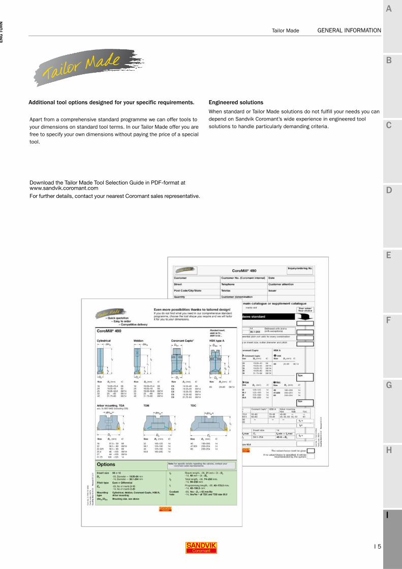
Additional tool options designed for your specific requirements.
Apart from a comprehensive standard programme we can offer tools to your dimensions on standard tool terms. In our Tailor Made offer you are free to specify your own dimensions without paying the price of a special tool.
Download the Tailor Made Tool Selection Guide in PDF-format at www.sandvik.coromant.com
For further details, contact your nearest Coromant sales representative.
Engineered solutions
When standard or Tailor Made solutions do not fulfill your needs you can depend on Sandvik Coromant’s wide experience in engineered tool solutions to handle particularly demanding criteria.

I 6
GENERAL INFORMATION Tailor Made
EN
G T
UR
N
A
B
C
D
E
F
G
H
I
GENERAL INFORMATION Tailor Made
Overview of Tailor Made product families
Parting & grooving
Inserts
CoroCut®T-Max®Q-Cut
- Insert width- Insert radius- Insert shape- Insert grade
Tools
T-Max Q-Cut®CoroCut®
- Coupling/shank size- Coupling type- Cutting depths- Cutting width- Tool length- Coolant supply- Insert system- Holder style- Diameters- Machining limitations
ThreadingInserts
CoroThread®266T-Max®U-Lock
- External/internal- Insert size - Profiles- Pitch- Taper angles- Crest form

I 7
Safety information GENERAL INFORMATION
EN
G T
UR
N
A
B
C
D
E
F
G
H
I
GENERAL INFORMATION Safety information
Safety information in connection with grinding of cemented carbideMaterial compositonMost metal products contain tungsten carbide and cobalt. Other substances that may be present in hard metal are titanium carbide, tantalum carbide, niobium carbide, chromium carbide, molybdenum carbide or vanadium carbide. Some grades contain titanium carbonitride and/or nickel.
Routes of exposureGrinding or heating of hard metal blanks or hard metal products will produce products that give off dangerous dust and fumes. Avoiding ingestion and contact with skin or eyes is very important.
Acute toxicityIntake of the aforementioned substances is toxic. Inhalation may cause irritation and inflammation of the airways. Significantly higher acute inhalation toxicity has been reported during simultaneous inhalation of cobalt and tungsten carbide compared to inhalation of cobalt alone.Skin contact can cause irritation and rash. Sensitive individuals may even experience an allergic reaction.
Chronic toxicityRepeated inhalation of aerosols containing cobalt may cause obstruction of the airways. Prolonged exposure to increased concentrations may cause lung fibrosis or lung cancer. Epidemiological studies indicate that workers previously exposed to high concentrations of tungsten carbide/cobalt carried an increased risk of developing lung cancer.Cobalt and nickel are potent skin sensitizers. Repeated or prolonged contact can cause irritation and sensitization.
Risk phrasesToxic: danger of serious damage to health by prolonged exposure through inhalationToxic when inhaledLimited evidence of a carcinogenic effect.May cause sensitization by inhalation and skin contact
Preventive measuresAvoid formation and inhalation of dust. Use adequate local exhaust ventilation to keep personal exposure well below nationally authorised limits.If ventilation is not available or adequate, use respirators appropriately approved for the purpose.Use safety goggles or glasses with side shields when necessary.Avoid repeated skin contact. Wear suitable gloves. Wash skin thoroughly after handling.Use suitable protective clothing. Launder clothing if needed.Do not eat, drink or smoke in the working area. Wash skin thoroughly before eating, drinking or smoking.

I 8
GENERAL INFORMATION Material cross reference list
EN
G T
UR
N
A
B
C
D
E
F
G
H
I
GENERAL INFORMATION Material cross reference list
Material cross reference list
ISO MC CMC CountryEurope Germany Great Britain Sweden USA France Italy Spain Japan
StandardDIN EN W.-nr. BS EN SS AISI/SAE/ASTM AFNOR UNI UNE JIS
P Unalloyed steel
Stee
l
P1.1.Z.AN 01.1 S235JR G2 1.0038 4360 40 C - 1311 A570.36 E 24-2 Ne - - STKM 12A;CP1.1.Z.AN 01.1 S235J2 G3 1.0116 4360 40 B - 1312 A573-81 65 E 24-U Fe37-3 - -P1.1.Z.AN 01.1 C15 1.0401 080M15 - 1350 1015 CC12 C15C16 F.111 -P1.1.Z.AN 01.1 C22 1.0402 050A20 2C/2D 1450 1020 CC20 C20C21 F.112 -P1.1.Z.AN 01.1 C15E 1.1141 080M15 32C 1370 1015 XC12 C16 C15K S15CP1.1.Z.AN 01.1 C25E 1.1158 - - - 1025 - - - S25CP1.1.Z.AN 01.1 S380N 1.8900 4360 55 E - 2145 A572-60 - FeE390KG - -P1.1.Z.AN 01.1 17MnV7 1.0870 4360 55 E - 2142 A572-60 NFA 35-501 E 36 - - -P1.1.Z.AN 02.1 55Si7 1.0904 250A53 45 2085 9255 55S7 55Si8 56Si7 -P1.1.Z.AN 02.2 - - - - 2090 9255 55S7 - - -P1.2.Z.AN 01.2 C35 1.0501 060A35 - 1550 1035 CC35 C35 F.113 -P1.2.Z.AN 01.2 C45 1.0503 080M46 - 1650 1045 CC45 C45 F.114 -P1.2.Z.AN 01.2 40Mn4 1.1157 150M36 15 - 1039 35M5 - - -P1.2.Z.AN 01.2 36MN5 1.1167 - - 2120 1335 40M5 - 36Mn5 SMn438(H)P1.2.Z.AN 01.2 28Mn6 1.1170 150M28 14A - 1330 20M5 C28Mn - SCMn1P1.2.Z.AN 01.2 C35G 1.1183 060A35 - 1572 1035 XC38TS C36 - S35CP1.2.Z.AN 01.2 C45E 1.1191 080M46 - 1672 1045 XC42 C45 C45K S45CP1.2.Z.AN 01.2 C53G 1.1213 060A52 - 1674 1050 XC48TS C53 - S50CP1.2.Z.AN 01.3 C55 1.0535 070M55 - 1655 1055 - C55 - -P1.2.Z.AN 01.3 C55E 1.1203 070M55 - - 1055 XC55 C50 C55K S55CP1.2.Z.AN 02.1 S275J2G3 1.0144 4360 43C - 1412 A573-81 E 28-3 - - SM 400A;B;CP1.2.Z.AN 02.1 S355J2G3+C2 1.0570 4360 50B - 2132 - E36-3 Fe52BFN/Fe52CFN - SM490A;B;C;YA;YBP1.2.Z.AN 02.1 S355J2G3 1.0841 150 M 19 - 2172 5120 20 MC 5 Fe52 F-431 -P1.3.Z.AN 01.3 C60E 1.0601 080A62 43D - 1060 CC55 C60 - -P1.3.Z.AN 01.3 C60E 1.1221 080A62 43D 1678 1060 XC60 C60 - S58CP1.3.Z.AN 01.4 C101E 1.1274 060 A 96 - 1870 1095 XC 100 - F-5117 -P1.3.Z.AN 01.4 C101u 1.1545 BW 1A - 1880 W 1 Y105 C36KU F-5118 SK 3P1.3.Z.AN 01.4 C105W1 - BW2 - 2900 W210 Y120 C120KU F.515 SUP4P1.3.Z.AN 02.1 S340 MGC 1.0961 - - - 9262 60SC7 60SiCr8 60SiCr8 -P1.4.Z.AN 01.1 11SMn30 1.0715 230M07 - 1912 1213 S250 CF9SMn28 11SMn28 SUM22P1.4.Z.AN 01.1 11SMnPb30 1.0718 - - 1914 12L13 S250Pb CF9SMnPb28 11SMnPb28 SUM22LP1.4.Z.AN 01.1 10SPb20 1.0722 - - - - 10PbF2 CF10SPb20 10SPb20 -P1.4.Z.AN 01.1 11SMn37 1.0736 240M07 1B - 1215 S 300 CF9SMn36 12SMn35 -P1.4.Z.AN 01.1 11SMnPb37 1.0737 - - 1926 12L14 S300Pb CF9SMnPb36 12SMnP35 -P1.4.Z.AN 01.2 35S20 1.0726 212M36 8M 1957 1140 35MF4 - F210G -P1.5.C.UT 01.1 GC16E 1.1142 030A04 1A 1325 1115 - - - -
Low-alloy steel
P2.1.Z.AN 02.1 16Mo3 1.5415 1501-240 - 2912 A204Gr.A 15D3 16Mo3KW 16Mo3 -P2.1.Z.AN 02.1 14Ni6 1.5622 - - - A350LF5 16N6 14Ni6 15Ni6 -P2.1.Z.AN 02.1 21NiCrMo2 1.6523 805M20 362 2506 8620 20NCD2 20NiCrMo2 20NiCrMo2 SNCM220(H)P2.1.Z.AN 02.1 17CrNiMo6 1.6587 820A16 - - - 18NCD6 - 14NiCrMo13 -P2.1.Z.AN 02.1 15Cr3 1.7015 523M15 - - 5015 12C3 - - SCr415(H)P2.1.Z.AN 02.1 55Cr3 1.7176 527A60 48 - 5155 55C3 - - SUP9(A)P2.1.Z.AN 02.1 15CrMo5 1.7262 - - 2216 - 12CD4 - 12CrMo4 SCM415(H)P2.1.Z.AN 02.1 13CrMo4-5 1.7335 1501-620Gr27 - - A182 F11;F12 15CD3.5 14CrMo4 5 14CrMo45 -
15CD4.5P2.1.Z.AN 02.1 10CrMo9 10 1.7380 1501-622 Gr.31;45 - 2218 A182 F.22 12CD9, 10 12CrMo9, 10 TU.H -P2.1.Z.AN 02.1 14MoV6 3 1.7715 1503-660-440 - - - - - 13MoCrV6 -P2.1.Z.AN 02.1 50CoMo4 1.7228 823M30 33 2512 - - 653M31 - -P2.1.Z.AN 02.2 14NiCr10 1.5732 - - - 3415 14NC11 16NiCr11 15NiCr11 SNC415(H)P2.1.Z.AN 02.2 14NiCr14 1.5752 655M13; A12 36A - 3415;3310 12NC15 - - SNC815(H)P2.1.Z.AN 02.1/02.2 16MnCr5 1.7131 (527M20) - 2511 5115 16MC5 16MnCr5 16MnCr5 -P2.1.Z.AN 02.1/02.2 34CrMo4 1.7220 708A37 19B 2234 4137;4135 35CD4 35CrMo4 34CrMo4 SCM432;SCCRM3P2.1.Z.AN 02.1/02.2 41CrMo4 1.7223 708M40 19A 2244 4140;4142 42CD4TS 41CrMo4 42CrMo4 SCM 440P2.1.Z.AN 02.1/02.2 42CrMo4 1.7225 708M40 19A 2244 4140 42CD4 42CrMo4 42CrMo4 SCM440(H)P2.1.Z.AN 03.11 14NiCrMo134 1.6657 832M13 36C - - - 15NiCrMo13 14NiCrMo131 -P2.2.Z.AN 02.1 31CrMo12 1.8515 722 M 24 - 2240 - 30 CD 12 30CrMo12 F-1712 -P2.2.Z.AN 02.1 39CrMoV13 9 1.8523 897M39 40C - - - 36CrMoV12 - -P2.2.Z.AN 02.1 41CrS4 1.7039 524A14 - 2092 L1 - 105WCR 5 - -P2.2.Z.AN 02.1 50NiCr13 1.2721 - - 2550 L6 55NCV6 - F-528 -P2.2.Z.AN 03.11 45WCrV7 1.2542 BS1 - 2710 S1 - 45WCrV8KU 45WCrSi8 -P2.2.Z.AN/P2.5.Z.HT 02.1/02.2 36CrNiMo4 1.6511 816M40 110 - 9840 40NCD3 38NiCrMo4(KB) 35NiCrMo4 -P2.2.Z.AN/P2.5.Z.HT 02.1/02.2 34CrNiMo6 1.6582 817M40 24 2541 4340 35NCD6 35NiCrMo6(KB) - -P2.2.Z.AN/P2.5.Z.HT 02.1/02.2 34Cr4 1.7033 530A32 18B - 5132 32C4 34Cr4(KB) 35Cr4 SCr430(H)P2.2.Z.AN/P2.5.Z.HT 02.1/02.2 41Cr4 1.7035 530A40 18 - 5140 42C4 41Cr4 42Cr4 SCr440(H)P2.2.Z.AN/P2.5.Z.HT 02.1/02.2 32CrMo12 1.7361 722M24 40B 2240 - 30CD12 32CrMo12 F.124.A -P2.2.Z.AN/P2.5.Z.HT 02.1/02.2 51CrV4 1.8159 735A50 47 2230 6150 50CV4 50CrV4 51CrV4 SUP10P2.2.Z.AN/P2.5.Z.HT 02.1/02.2 41CrAlMo7 1.8509 905M39 41B 2940 - 40CAD6, 12 41CrAlMo7 41CrAlMo7 -P2.3.Z.AN 02.1 100Cr6 1.3505 534A99 31 2258 52100 100C6 100Cr6 F.131 SUJ2

I 9
Material cross reference list GENERAL INFORMATION
EN
G T
UR
N
A
B
C
D
E
F
G
H
I
GENERAL INFORMATION Material cross reference list
Material cross reference list
ISO MC CMC CountryEurope Germany Great Britain Sweden USA France Italy Spain Japan
StandardDIN EN W.-nr. BS EN SS AISI/SAE/ASTM AFNOR UNI UNE JIS
P P2.3.Z.AN/H1.2.Z.HA 02.1/02.2 105WCr6 1.2419 - - 2140 - 105WC13 10WCr6 105WCr5 SKS31
Stee
l
P2.3.Z.AN/H1.2.Z.HA - - - - - - - - 107WCr5KU - SKS2, SKS3P2.3.Z.AN/H1.2.Z.HA 02.1/02.2 - 1.2714 - - - L6 55NCDV7 - F.520.S SKT4P2.3.Z.AN/H1.3.Z.HA 02.1/02.2 100Cr6 1.2067 BL3 - - L3 Y100C6 - 100Cr6 -P2.4.Z.AN 02.1 16MnCr5 1.7139 - - 2127 - - - - -P2.5.Z.HT 02.1 16Mo5 1.5423 1503-245-420 - - 4520 - 16Mo5 16Mo5 -P2.5.Z.HT 02.1 40NiCrMo8-4 1.6562 311-Type 7 - - 8740 - 40NiCrMo2(KB) 40NiCrMo2 SNCM240P2.5.Z.HT 02.1 42Cr4 1.7045 - - 2245 5140 - - 42Cr4 SCr440P2.5.Z.HT 02.1 31NiCrMo14 1.5755 830 M 31 - 2534 - - - F-1270 -P2.5.Z.HT 02.2 36NiCr6 1.5710 640A35 111A - 3135 35NC6 - - SNC236P2.6.C.UT 02.1 22Mo4 1.5419 605A32 - 2108 8620 - - F520.S -P2.6.C.UT 02.1/02.2 25CrMo4 1.7218 1717CDS110 - 2225 4130 25CD4 25CrMo4(KB) AM26CrMo4 SCM420;SCM430P2.6.C.UT 06.2 - - - - 2223 - - - - -
High-alloy steel
P3.0.Z.AN 03.11 X210Cr12 1.2080 BD3 - - D3 Z200C12 X210Cr13KU X210Cr12 SKD1X250Cr12KU
P3.0.Z.AN 03.11 X43Cr13 1.2083 - - 2314 - - - - -P3.0.Z.AN 03.11 X40CrMoV5 1 1.2344 BH13 - 2242 H13 Z40CDV5 X35CrMoV05KU X40CrMoV5 SKD61
X40CrMoV511KUP3.0.Z.AN 03.11 X100CrMoV5 1 1.2363 BA2 - 2260 A2 Z100CDV5 X100CrMoV51KU X100CrMoV5 SKD12P3.0.Z.AN 03.11 X210CrW12 1.2436 - - 2312 - - X215CrW12 1KU X210CrW12 SKD2P3.0.Z.AN 03.11 X30WCrV9 3 1.2581 BH21 - - H21 Z30WCV9 X28W09KU X30WCrV9 SKD5
X30WCrV9 3KUP3.0.Z.AN 03.11 X165CrMoV 12 1.2601 - - 2310 - - X165CrMoW12KU X160CrMoV12 -P3.0.Z.AN 03.21 X155CrMoV12-1 1.2379 - - 2736 HNV3 - - - -P3.0.Z.HT 03.11 X8Ni9 1.5662 1501-509;510 - - ASTM A353 - X10Ni9 XBNi09 -P3.0.Z.HT 03.11 12Ni19 1.5680 - - - 2515 Z18N5 - - -P3.1.Z.AN 03.11 S6-5-2 1.3343 4959BA2 - 2715 D3 Z40CSD10 15NiCrMo13 - SUH3P3.1.Z.AN 03.13 - - BM 2 - 2722 M 2 Z85WDCV HS 6-5-2-2 F-5603. SKH 51P3.1.Z.AN 03.13 HS 6-5-2-5 1.3243 BM 35 - 2723 M 35 6-5-2-5 HS 6-5-2-5 F-5613 SKH 55P3.1.Z.AN 03.13 HS 2-9-2 1.3348 - - 2782 M 7 - HS 2-9-2 F-5607 -P3.2.C.AQ 06.33 G-X120Mn12 1.3401 Z120M12 - 2183 L3 Z120M12 XG120Mn12 X120Mn12 SCMnH/1
Ferritic/martensitic stainless steel
P5.0.Z.AN 05.11/15.11 X10CrAL13 1.4724 403S17 - - 405 Z10C13 X10CrAl12 F.311 SUS405P5.0.Z.AN 05.11/15.11 X10CrAL18 1.4742 430S15 60 - 430 Z10CAS18 X8Cr17 F.3113 SUS430P5.0.Z.AN 05.11/15.11 X10CrAL2-4 1.4762 - - 2322 446 Z10CAS24 X16Cr26 - SUH446P5.0.Z.AN 05.11/15.11 X1CrMoTi18-2 1.4521 - - 2326 S44400 - - - -P5.0.Z.AN/P5.0.Z.HT 05.11/15.11 X6Cr13 1.4000 403S17 - 2301 403 Z6C13 X6Cr13 F.3110 SUS403P5.0.Z.AN/P5.0.Z.HT - X7Cr14 1.4001 - - - - - - F.8401 -P5.0.Z.AN/P5.0.Z.HT 05.11/15.11 X10Cr13 1.4006 410S21 56A 2302 410 Z10C14 X12Cr13 F.3401 SUS410P5.0.Z.AN/P5.0.Z.HT 05.11/15.11 X6Cr17 1.4016 430S15 960 2320 430 Z8C17 X8Cr17 F3113 SUS430P5.0.Z.AN/P5.0.Z.HT 05.11/15.11 X6CrAL13 1.4002 405S17 - - 405 Z8CA12 X6CrAl13 - -P5.0.Z.AN/P5.0.Z.HT 05.11/15.11 X20Cr13 1.4021 420S37 - 2303 420 Z20C13 X20Cr13 - -P5.0.Z.AN/P5.0.Z.HT 05.11/15.11 X6CrMo17-1 1.4113 434S17 - 2325 434 Z8CD17.01 X8CrMo17 - SUS434P5.0.Z.HT 03.11 X45CrS9-3-1 1.4718 401S45 52 - HW3 Z45CS9 X45GrSi8 F322 SUH1P5.0.Z.HT 05.11/15.11 X85CrMoV18-2 1.4748 443S65 59 - HNV6 Z80CSN20.02 X80CrSiNi20 F.320B SUH4P5.0.Z.HT 05.11/15.11 X20CrMoV12-1 1.4922 - - 2317 - - X20CrMoNi 12 01 - -P5.0.Z.PH 05.11/15.11 X12CrS13 1.4005 416 S 21 - 2380 416 Z11CF13 X12 CrS 13 F-3411 SUS 416P5.0.Z.PH 05.11/15.11 X46Cr13 1.4034 420S45 56D 2304 - Z40CM X40Cr14 F.3405 SUS420J2P5.0.Z.PH 05.11/15.11 X19CrNi17-2 1.4057 431S29 57 2321 431 Z15CNi6.02 X16CrNi16 F.3427 SUS431P5.0.Z.PH 05.12/15.12 X5CrNiCuNb16-4 1.4542 1.4548 - - - 630 Z7CNU17-04 - - -P5.0.Z.PH 15.21 X4 CrNiMo16-5 1.4418 - - 2387 - Z6CND16-04-01 - - -P5.1.Z.AN/P5.0.Z.HT 05.11/15.11 X14CrMoS17 1.4104 - - 2383 430F Z10CF17 X10CrS17 F.3117 SUS430F
Trade namesP2.1.Z.AN 02.1 OVAKO 520M (Ovako Steel) P2.2.Z.AN 02.1 1.0045 FORMAX (Uddeholm Tooling)P2.2.Z.AN 02.1 IMACRO NIT (Imatra Steel)P2.5.Z.HT 02.2 INEXA 482 (XM) (Inexa Profil)P1.2.Z.AN S355J2G3(XM) P1.2.Z.AN C45(XM) P1.2.Z.AN 16MnCrS5(XM) P2.5.Z.HT INEXA280(XM) P2.5.Z.HT 02.2 070M20(XM) P2.5.Z.HT 02.2 HARDOX 500 (SSAB – Swedish Steel Corp.)P2.5.Z.HT WELDOX 700 (SSAB – Swedish Steel Corp.)

I 10
GENERAL INFORMATION Material cross reference list
EN
G T
UR
N
A
B
C
D
E
F
G
H
I
GENERAL INFORMATION Material cross reference list
Material cross reference list
ISO MC CMC CountryEurope Germany Great Britain Sweden USA France Italy Spain Japan
StandardDIN EN W.-nr. BS EN SS AISI/SAE/ASTM AFNOR UNI UNE JIS
M Austenitic stainless steel
Stai
nles
s st
eel
M1.0.Z.AQ 05.11/15.11 X3CrNiMo13-4 1.4313 425C11 - 2385 CA6-NM Z4CND13.4M (G)X6CrNi304 - SCS5Z38C13M
M1.0.Z.AQ/M1.0.C.UT 05.11/15.11 X53CrMnNiN21-9 1.4871 349S54 - - EV8 Z52CMN21.09 X53CrMnNiN21 9 - SUH35, SUH36M1.0.Z.AQ/M1.0.C.UT 05.21/15.21 X2CrNiN18-10 1.4311 304S62 - 2371 304LN Z2CN18.10 - - SUS304LNM1.0.Z.AQ/M1.0.C.UT 05.21/15.21 X2CrNiMoN17-13-3 1.4429 - - 2375 316LN Z2CND17.13 - - SUS316LNM1.0.Z.AQ/M1.0.C.UT 05.21/15.21 X2CrNiMo17-12-2 1.4404 316S13 - 2348 316L Z2CND17-12 X2CrNiMo1712 - -M1.0.Z.AQ/M1.0.C.UT 05.21/15.21 X2CrNiMo18-14-3 1.4435 316S13 - 2353 316L Z2CND17.12 X2CrNiMo17 12 - SCS16, SUS316LM1.0.Z.AQ/M1.0.C.UT 05.21/15.21 X3CrNiMo17-3-3 1.4436 316S33 - 2343, 2347 316 Z6CND18-12-03 X8CrNiMo1713 - -M1.0.Z.AQ/M1.0.C.UT 05.21/15.21 X2CrNiMo18-15-4 1.4438 317S12 - 2367 317L Z2CND19.15 X2CrNiMo18 16 - SUS317LM1.0.Z.AQ/M1.0.C.UT 05.21/15.21 X6CrNiNb18-10 1.4550 347S17 58F 2338 347 Z6CNNb18.10 X6CrNiNb18 11 F.3552 F.3524 SUS347M1.0.Z.AQ/M1.0.C.UT 05.21/15.21 X6CrNiMoTi17-12-2 1.4571 320S17 58J 2350 316Ti Z6NDT17.12 X6CrNiMoTi17 12 F.3535 -M1.0.Z.AQ/M1.0.C.UT 05.21/15.21 X10CrNiMoNb 18-12 1.4583 - - - 318 Z6CNDNb17 13B X6CrNiMoNb17 13 - -M1.0.Z.AQ/M1.0.C.UT 05.21/15.21 X15CrNiSi20-12 1.4828 309S24 - - 309 Z15CNS20.12 - - SUH309M1.0.Z.AQ/M1.0.C.UT 05.21/15.21 X2CrNiMoN17-11-2 1.4406 301S21 58C 2370 308 Z1NCDU25.20 - F.8414 SCS17M1.0.Z.AQ 05.21/15.21 X1CrNiMoCuN20-18-7 1.4547 - - 2378 S31254 Z1CNDU20-18-06AZ - - -M1.0.Z.AQ/M1.0.C.UT 05.21/15.21 X9CrNi18-8 1.4310 - - 2331 301 Z12CN17.07 X12CrNi17 07 F.3517 SUS301M1.0.Z.PH 05.22/15.22 X7CrNiAL17-7 1.4568 1.4504 316S111 - - 17-7PH Z8CNA17-07 X2CrNiMo1712 - -M1.0.Z.AQ/M1.0.C.UT 05.21/15.21 X2CrNi19-11 1.4306 304S11 - 2352 304L Z2CN18-10 X2CrNi18 11 - -
304S12M1.1.Z.AQ 05.21/15.21 - - 304S31 58E 2332, 2333 304 Z6CN18.09 X5CrNi18 10 F.3504 F.3541 SUS304M1.1.Z.AQ 05.21/15.21 X5CrNi18-10 1.4301 304S15 58E 2332 304 Z6CN18.09 X5CrNi18 10 F.3551 SUS304M1.1.Z.AQ 05.21/15.21 X5CrNiMo17-2-2 1.4401 316S16 58J 2347 316 Z6CND17.11 X5CrNiMo17 12 F.3543 SUS316M1.1.Z.AQ 05.21/15.21 X6CrNiTi18-10 1.4541 321S12 58B 2337 321 Z6CNT18.10 X6CrNiTi18 11 F.3553 F.3523 SUS321M1.2.Z.AQ 05.21/15.21 X8CrNiS18-9 1.4305 303S21 58M 2346 303 Z10CNF 18.09 X10CrNiS 18.09 F.3508 SUS303
Super austenitic (Ni>20%) stainless steel
M2.0.C.AQ 20.11 G-X40NiCrSi36-18 1.4865 330C11 - - - - XG50NiCr39 19 - SCH15M2.0.Z.AQ 05.21/15.21 X1NiCrMoCu25-20-5 1.4539 - - 2562 UNS V 0890A Z2 NCDU25-20 - - -M2.0.Z.AQ 05.21/15.21 X8CrNi25-21 1.4845 310S24 - 2361 310S Z12CN25 20 X6CrNi25 20 F.331 SUH310M2.0.Z.AQ 20.11 X12NiCrSi36 16 1.4864 - - - 330 Z12NCS35.16 F-3313 - SUH330M2.0.Z.AQ 05.23/15.23 X1NiCrMoCu31-27-4 1.4563 - - 2584 NO8028 Z1NCDU31-27-03 - - -
Duplex (austenitic/ferritic) stainless steel
M3.1.Z.AQ/M3.1.C.AQ 05.51/15.51 X2CrNiN23-4 1.4362 - - 2376 S31500 - - - -M3.1.Z.AQ/M3.1.C.AQ 05.51/15.51 X8CrNiMo27-5 - - - 2324 S32900 - - - -M3.2.Z.AQ/M3.2.C.AQ 05.52/15.52 X2CrNiN23-4 - - - 2327 S32304 Z2CN23-04AZ - - -M3.2.Z.AQ/M3.2.C.AQ 05.52/15.52 - - - - 2328 - - - - -M3.2.Z.AQ/M3.2.C.AQ 05.52/15.52 X2CrNiMoN22-53 - - - 2377 S31803 Z2CND22-05-03 - - -
Trade namesM1.1.Z.AQ 05.21/15.21 SANMAC 304 (Sandvik Steel) M1.1.Z.AQ 05.21/15.21 1.0045 SANMAC 304L (Sandvik Steel) M1.1.Z.AQ 05.21/15.21 SANMAC 316 (Sandvik Steel) M1.1.Z.AQ 05.21/15.21 SANMAC 316L (Sandvik Steel) M1.0.Z.AQ 05.23/15.23 254 SMO M2.0.Z.AQ 05.23/15.23 654 SMOM3.2.Z.AQ 05.52/15.52 SANMAC SAF 2205 (Sandvik Steel) M3.2.Z.AQ 05.52/15.52 SANMAC SAF 2507 (Sandvik Steel)

I 11
Material cross reference list GENERAL INFORMATION
EN
G T
UR
N
A
B
C
D
E
F
G
H
I
GENERAL INFORMATION Material cross reference list
Material cross reference list
ISO MC CMC CountryEurope Germany Great Britain Sweden USA France Italy Spain Japan
StandardDIN EN W.-nr. BS EN SS AISI/SAE/ASTM AFNOR UNI UNE JIS
K Malleable cast iron
Cast
iron
K1.1.C.NS 07.1 - - 8 290/6 - 0814 - MN 32-8 - - FCMB310K1.1.C.NS 07.1 EN-GJMB350-10 0.8135 B 340/12 - 0815 32510 MN 35-10 - - FCMW330K1.1.C.NS 07.2 EN-GJMB450-6 0.8145 P 440/7 - 0852 40010 Mn 450 GMN 45 - FCMW370K1.1.C.NS 07.2 EN-GJMB550-4 0.8155 P 510/4 - 0854 50005 MP 50-5 GMN 55 - FCMP490
P 570/3 0858 70003 MP 60-3 FCMP540K1.1.C.NS 07.2 EN-GJMB650-2 0.8165 P570/3 - 0856 A220-70003 Mn 650-3 GMN 65 - FCMP590K1.1.C.NS 07.3 EN-GJMB700-2 0.8170 P690/2 - 0862 A220-80002 Mn700-2 GMN 70 - FCMP690
Grey cast iron
K2.1.C.UT 08.1 - - - - 0100 - - - - -K2.1.C.UT 08.1 EN-GJL-100 0.6010 - - 0110 No 20 B Ft 10 D - - FC100K2.1.C.UT 08.1 EN-GJL-150 0.6015 Grade 150 - 0115 No 25 B Ft 15 D G 15 FG 15 FC150K2.1.C.UT 08.1 EN-GJL-200 0.6020 Grade 220 - 0120 No 30 B Ft 20 D G 20 - FC200K2.1.C.UT 08.2 EN-GJL-250 0.6025 Grade 260 - 0125 No 35 B Ft 25 D G 25 FG 25 FC250K2.1.C.UT 08.2 EN-JLZ 0.6040 Grade 400 - 0140 No 55 B Ft 40 D - - -K2.2.C.UT 08.2 EN-GJL-300 0.6030 Grade 300 - 0130 No 45 B Ft 30 D G 30 FG 30 FC300K2.2.C.UT 08.2 EN-GJL-350 0.6035 Grade 350 - 0135 No 50 B Ft 35 D G 35 FG 35 FC350K2.3.C.UT 08.3 GGL-NiCr20-2 0.6660 L-NiCuCr202 - 0523 A436 Type 2 L-NC 202 - - -
Nodular cast iron
K3.1.C.UT 09.1 EN-GJS-400-15 0.7040 SNG 420/12 - 0717-02 60-40-18 FCS 400-12 GS 370-17 FGE 38-17 FCD400K3.1.C.UT 09.1 EN-GJS-400-18-LT 0.7043 SNG 370/17 - 0717-12 - FGS 370-17 - - -K3.1.C.UT 09.1 EN-GJS-350-22-LT 0.7033 - - 0717-15 - - - - -K3.1.C.UT 09.1 EN-GJS-800-7 0.7050 SNG 500/7 - 0727 80-55-06 FGS 500-7 GS 500 FGE 50-7 FCD500K3.2.C.UT 09.2 EN-GJS-600-3 0.7060 SNG 600/3 - 0732-03 - FGS 600-3 - - FCD600K3.3.C.UT 09.2 EN-GJS-700-2 0.7070 SNG 700/2 - 0737-01 100-70-03 FGS 700-2 GS 700-2 FGS 70-2 FCD700K3.5.C.UT - EN-GJSA-XNiCr20-2 0.7660 Grade S6 - 0776 A43D2 S-NC 202 - - -
Compacted graphite iron
K4.1.C.UT - EN-GJV-300K4.1.C.UT - EN-GJV-350K4.2.C.UT - EN-GJV-400K4.2.C.UT - EN-GJV-450K4.2.C.UT - EN-GJV-500
Austempered ductile iron
K5.1.C.NS - EN-GJS-800-8 - - - - ASTM A897 No. 1 - - - -K5.1.C.NS - EN-GJS-1000-5 - - - - ASTM A897 No. 2 - - - -K5.2.C.NS - EN-GJS-1200-2 - - - ASTM A897 No. 3 - - - -K5.2.C.NS - EN-GJS-1400-1 - - - - ASTM A897 No. 4 - - - -K5.3.C.NS - - - - - - ASTM A897 No. 5 - - - -

I 12
GENERAL INFORMATION Material cross reference list
EN
G T
UR
N
A
B
C
D
E
F
G
H
I
GENERAL INFORMATION Material cross reference list
Material cross reference list
ISO MC CMC CountryEurope Germany Great Britain Sweden USA France Italy Spain Japan
StandardDIN EN W.-nr. BS EN SS AISI/SAE/ASTM AFNOR UNI UNE JIS
N Aluminium based alloys
Non-
ferr
ous
met
als
N1.3.C.AG 30.21 G-AISI9MGWA 3.2373 - - 4251 SC64D A-S7G - - C4BSN1.3.C.UT 30.21 G-ALMG5 - LM5 - 4252 GD-AISI12 A-SU12 - - AC4AN1.3.C.UT/N1.3.C.AG 30.21/30.22 - - LM25 - 4244 356.1 - - - A5052N1.3.C.UT - GD-AlSi12 - - - 4247 A413.0 - - - A6061N1.3.C.AG - GD-AlSi8Cu3 - LM24 - 4250 A380.1 - - - A7075N1.3.C.UT - G-AlSi12(Cu) - LM20 - 4260 A413.1 - - - ADC12N1.3.C.UT - G-AlSi12 - LM6 - 4261 A413.2 - - - -N1.3.C.AG - G-AlSi10Mg(Cu) - LM9 - 4253 A360.2 - - - -
S Nickel based alloys
Heat
resi
stan
t sup
er a
lloys
S2.0.Z.AG 20.22 S-NiCr13A16MoNb LW2 4670 mar-46 - - 5391 NC12AD - - -S2.0.C.UT 20.24 NiCo15Cr10MoAlTi LW2 4674 - - - AMS 5397 - - - -S2.0.Z.AG 20.22 NiFe35Cr14MoTi LW2.4662 - - - 5660 ZSNCDT42 - - -S2.0.Z.AG 20.22 NiCr19Fe19NbMo LW2.4668 HR8 - - 5383 NC19eNB - - -S2.0.Z.AG 20.22 NiCr20TiAk 2.4631 Hr401.601 - - - NC20TA - - -S2.0.Z.AG 20.22 NiCr19Co11MoTi 2.4973 - - - AMS 5399 NC19KDT - - -S2.0.Z.AG 20.22 NiCr19Fe19NbMo LW2.4668 - - - AMS 5544 NC20K14 - - -S2.0.Z.AN 20.21 - 2.4603 - - - 5390A NC22FeD - - -S2.0.Z.AN 20.21 NiCr22Mo9Nb 2.4856 - - - 5666 NC22FeDNB - - -S2.0.Z.AN 20.21 NiCr20Ti 2.4630 HR5.203-4 - - - NC20T - - -S2.0.Z.AG 20.22 NiCu30AL3Ti 2.4375 3072-76 - - 4676 - - - -
Cobalt alloys
- - CoCr20W15Ni - - - - 5537C, AMS KC20WN - - -S3.0.Z.AG 20.32 CoCr22W14Ni LW2.4964 - - - 5772 KC22WN - - -
Titanium alloys
S4.2.Z.AN 23.22 TiAl5Sn2.5 3.7115.1 TA14/17 - - UNS R54520 T-A5E - - -UNS R56400
S4.2.Z.AN 23.22 TiAl6V4 3.7165.1 TA10-13/TA28 - - UNS R56401 T-A6V - - -S4.3.Z.AN 23.22 TiAl5V5Mo5Cr3 - - - - - - - - -S4.2.Z.AN 23.22 TiAl4Mo4Sn4Si0.5 3.7185 - - - - - - - -
Trade names
Iron based alloysS2.0.Z.UT/S2.0.Z.AN 20.11 Incoloy 800
Nickel based alloysS2.0.Z.AN 20.2 Haynes 600S2.0.Z.AN 20.2 Nimocast PD16 S2.0.Z.AG 20.2 Nimonic PE 13 S2.0.Z.AG 20.2 Rene 95 S2.0.Z.AN 20.21 Hastelloy C S2.0.Z.AN 20.21 Incoloy 825 S2.0.Z.AN 20.21 Inconel 600 S2.0.Z.AN 20.21 Monet 400 S2.0.Z.AG 20.22 Inconel 700 S2.0.Z.AG S2.0.Z.AG Inconel 718 S2.0.Z.AG 20.22 Mar – M 432 S2.0.Z.AG 20.22 Nimonic 901 S2.0.Z.AG 20.22 Waspaloy S2.0.C.NS 20.24 Jessop G 64
Cobalt alloysS3.0.Z.AG 20.3 Air Resist 213S3.0.Z.AG 20.3 Jetalloy 209
H Hardened materials
Hard
ened
mat
eria
ls
H1.2.Z.HA 04.1 X100CrMo13 1.4108 - - 2258 08 440A - - - C4BSH1.3.Z.HA 04.1 X110CrMoV15 1.4111 - - 2534 05 610 - - - AC4AH1.2.Z.HA 04.1 X65CrMo14 - - - 2541 06 0-2 - - - AC4A

I 13
Coromant Recycling Concept (CRC) GENERAL INFORMATION
EN
G T
UR
N
A
B
C
D
E
F
G
H
I
GENERAL INFORMATION Coromant Recycling Concept (CRC)
For the sake of the environment
Get into the Sandvik Coromant Recycling Concept (CRC) now!The Sandvik Coromant Recycling Concept (CRC) is a comprehensive service for used carbide inserts and solid carbide tools offered by Sandvik Coromant to all its customers. In the light of increasing consumption of non-renewable raw materials, the economic management of dwindling resources is a duty owed by all manufacturers. Sandvik Coromant is playing its part by offering to collect used carbide inserts and solid carbide tools and recycle them in the most environmently friendly way.All used carbide inserts are collected in the collection box at the workplace.When the collection box is sufficiently full, its contents are transferred to the transport box. The full transport box is then sent to the nearest Sandvik Coromant office or to your Sandvik Coromant dealer who can also give you more information.
The benefits of the CRC speak for themselves
- A worldwide ISO and OHAS certified recycling system.- Open to all Sandvik Coromant customers.- Simple procedure with collection and transport boxes.- Less waste, easing the burden on the environment.- Better utilisation of resources.- Other manufacturers' carbide inserts are also accepted.
Order collection boxes for each lathe, milling machine, drill or for your machining centre. We recommend one collection box for inserts and one separate box for solid carbide tools for each cutting workplace.For detailed instructions on how to sell your used cemented carbide, please visit www.sandvik.coromant.com and select your market.
Order numbersCollection box (yellow): 91617Transport box for solid carbide tools (plywood): 92994Transport box inserts (plywood): 92995

I 14
GENERAL INFORMATION Code keys
EN
G T
UR
N
A
B
C
D
E
F
G
H
I
GENERAL INFORMATION Code keys
General turning inserts
Inserts, metric
Inserts, inch
Inserts, advanced cutting materials, metric
Inserts, advanced cutting materials, inch
1 Insert shape
C D
K R
S T
V W
2 Insert clearance angle
B C
E N
P O Specific description
3 Tolerances, metric
Class S IC / W1G ±0.13 ±0.025M ±0.13 ±0.05 ±0.151)
U ±0.13 ±0.08 ±0.251)
E ±0.025 ±0.0251)Varies depending on the size of IC. See below.
Inscribed circle Tolerance classIC mm M U3.975.05.566.0 ±0.05 ±0.086.358.09.52510.012.0 ±0.08 ±0.1312.715.87516.0 ±0.10 ±0.1819.0520.025.0 ±0.13 ±0.2525.431.75 ±0.15 ±0.2532.0For positive inserts iC is valid for a sharp corner. See cutting edge condition F. (Picture 8).
3 Tolerances, inch
A: Theoretical diameter of the insert inscribed circle.T: Thickness of the insert.B: See figures.
Tolerances in inchClass B: A: T:
A ±.0002 ±.001 ±.001B .0002 .001 .005C .0005 .001 .001D .0005 .001 .005E .001 .001 .001F .0002 .0005 .001G .001 .001 .005H .0005 .0005 .001J .0002 .002-.005 .001K .0005 .002-.005 .001L .001 .002-.005 .001M .002-.005 .002-.005 .005U .005-.012 .005-.010 .005N .002-.010 .002-.004 .001
B BB
A

I 15
Code keys GENERAL INFORMATION
EN
G T
UR
N
A
B
C
D
E
F
G
H
I
GENERAL INFORMATION Code keys
General turning inserts4 Insert type
A Q
G R
M T
N W
P X
Special design
6 Insert thickness, S mm, inch 7 Nose radius, RE mm, inch
Metric: Inch: Actual dimension:
Metric Inch inch00 = 0 00 Round
01 S = 1.59 1 S = .0625 01 = 0.1 03 .004T1 S = 1.98 (1.2) S = .075 02 = 0.2 0 .00802 S = 2.38 (1.5) S = 3/32 04 = 0.4 1 = 1/64 .015603 S= 3.18 2 S = 1/8 05 = 0.5T3 S = 3.97 (2.5) S = 5/32 08 = 0.8 2 = 1/32 .031204 S = 4.76 3 S = 3/16 10 = 1.005 S = 5.56 4 S = 1/4 12 = 1.2 3 = 3/64 .04706 S = 6.35 5 S = 5/16 15 = 1.507 S = 7.94 6 S = 3/8 16 = 1.6 4 = 1/16 .062509 S = 9.52 6.3 S = .394 24 = 2.4 6 = 3/32 .09410 S = 10.00 7.6 S = .475 32 = 3.2 8 = 1/8 .12512 S = 12.00
9 Hand of tool 10 Chamfer width metric, inch 11 Chamfer angle
Metric:R Feed 010 BN = 0.10 15 GB = 15°
025 BN = 0.25 20 GB = 20°070 BN = 0.70150 BN = 1.50200 BN = 2.00
L Feed Inch:03 BN = .00308 BN = .00830 BN = .03060 BN = .060
N Feed Feed 80 BN = .080
For more information, see code key on page I16
12 Manufacturer’s option
The ISO code consists of nine symbols including 8 and 9 which are used only when required. In addition the manufacturer may add further three symbols e. g.
- WF = Wiper – finishing- WMX = Wiper, medium machining- PF = ISO P – finishing- PR = ISO P – roughing
8 Cutting edge condition
F Sharp cutting edge
A ER treated cutting edge (ANSI)
E ER treated cutting edge
T Negative land
K Double negative lands
S Negative land and ER treated cutting edge
5 Insert size
Cutting edge length, metricIC mm IC inch C D R S T V W K
3.18 1/8" 05Inscribed circle is indicated in 1/8".
3.97 5/32" 06 025.0 055.56 7/32" 096.0 066.35 1/4" 06 07 11 11 048.0 089.525 3/8" 09 11 09 09 16 16 06 16*)
10.0 10.0 1012.0 1212.7 1/2" 12 15 12 12 22 22 0813 13 1315.875 5/8" 16 15 15 2716.0 1619.0 3/4" 19 19 19 3320.0 2025.0 251)
25.4 1" 25 252) 25
1) Metric base design 31.75 1/4" 312) Inch base design 32 32
*) For insert shape K (KNMX, KNUX) only the theoretical cutting edge length is indicated.
I 16
GENERAL INFORMATION Code keys
EN
G T
UR
N
A
B
C
D
E
F
G
H
I
GENERAL INFORMATION Code keys
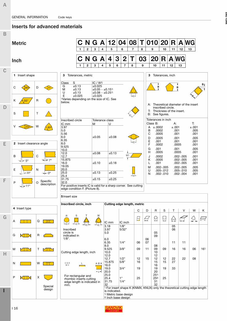
Inserts for advanced materials
Metric
Inch
1 Insert shape
C D
K R
S T
V W
2 Insert clearance angle
B C
E N
P O Specific description
3 Tolerances, metric
Class S IC / W1G ±0.13 ±0.025M ±0.13 ±0.05 − ±0.151)
U ±0.13 ±0.08 − ±0.251)
E ±0.025 ±0.0251)Varies depending on the size of IC. See below.
Inscribed circle Tolerance classIC mm M U3.975.05.566.0 ±0.05 ±0.086.358.09.52510.012.0 ±0.08 ±0.1312.715.87516.0 ±0.10 ±0.1819.0520.025.0 ±0.13 ±0.2525.431.75 ±0.15 ±0.2532.0For positive inserts iC is valid for a sharp corner. See cutting edge condition F. (Picture 8).
3 Tolerances, inch
A: Theoretical diameter of the insert inscribed circle.
T: Thickness of the insert.B: See figures.
Tolerances in inchClass B: A: T:A ±.0002 ±.001 ±.001B .0002 .001 .005C .0005 .001 .001D .0005 .001 .005E .001 .001 .001F .0002 .0005 .001G .001 .001 .005H .0005 .0005 .001J .0002 .002-.005 .001K .0005 .002-.005 .001L .001 .002-.005 .001M .002-.005 .002-.005 .005U .005-.012 .005-.010 .005N .002-.010 .002-.004 .001
B B
B
A
4 Insert type
A Q
G R
M T
N W
P X
Special design
5 Insert size
Inscribed circle, inch Cutting edge length, metric
IC mm IC inch
C D R S T V W K
3.18 1/8" 05Inscribed circle is indicated in 1/8".
3.97 5/32" 065.0 05
096.0 066.35 1/4" 06 07 11 118.0 089.525 3/8" 09 11 09 09 16 16 06 16*)
Cutting edge length, inch 10.0 1012.0 1212.7 1/2" 12 15 12 12 22 22 0815.875 5/8" 16 15 15 2716.0 1619.0 3/4" 19 19 19 3320.0 2025.0 251)
25.4 1" 25 252) 2531.75 1/4" 3132 32*) For insert shape K (KNMX, KNUX) only the theoretical cutting edge length is indicated.1) Metric base design2) Inch base design
For rectangular and rhombic inserts cutting edge length is indicated in mm.

I 17
Code keys GENERAL INFORMATION
EN
G T
UR
N
A
B
C
D
E
F
G
H
I
GENERAL INFORMATION Code keys
8 Cutting edge condition
F Sharp cutting edge
E (A) ER treated cutting edge
A (inch)E (metric)
T Negative land
K Double negative lands
S Negative land and ER treated cutting edge
9 Chamfer widthISO mm ANSI inch010 BN = 0.10 03 BN = (.003)015 BN = 0.15 06 BN = (.006)020 BN = 0.20 08 BN = (.0078)025 BN = 0.25 08 BN = (.0098)070 BN = 0.70 30 BN = (.030)150 BN = 1.50 60 BN = (.060)200 BN = 2.00 80 BN = (.080)
10 Chamfer angle, degrees
15 GB = 15° 30 GB = 30°20 GB = 20° 35 GB = 35°25 GB = 25°
11 Hand of insert
Inserts designed solely for machining in left or right direction are indicated as below.
R Right hand design
L Left hand design
12 Insert Type (CBN)
To allow a variety of machining demands to be met, several types of inserts comprising CBN and PCD is manufactured. To easy identify the different types Sandvik Coromant uses a letter to denote the variants.
A CBN, Multi Corner Inserts- Fully indexable- CBN top to bottom of the carbide carrier corners
B CBN, Multi Corner Inserts- Fully indexable- CBN brazed to the top and bottom of the carbide carrier corners.
E CBN, Single tip inserts- Non-indexable- CBN brazed to the top of one of the carbide carrier corners
F CBN, Multi tip inserts- Indexable- CBN brazed to each corner of the carbide carrier
D CBN, Full top inserts- Indexable- CBN sintered to the complete top surface of the carbide carrier
M CBN, Solid inserts- Fully indexable- Complete insert mode from CBN
13 Wiper Geometry
Our unique Wiper and Xcel technologies can be used to boost productivity and generate superior surface finish.
WG Wiper geometry for general purpose machiningAllows high feed rates in HPTSuitable for finish machining of GCI
WH Wiper geometry optimized for HPTLow cutting forces for superior surface finishDesigned for peak performance at HPT finishing feed rates
Xcel XA
Allows the use of higher feed rates than other wiper geometries Maintains surface finish
6 Insert thickness, S mm, inch 7 Nose radius, RE mm, inch
Metric: Inch: Actual dimension:Metric Inch
00 = 0 00 Round01 S = 1.59 1. S = .0625 01 = 0.1 03 .004T1 S = 1.98 (1.2) S = .075 02 = 0.2 0 .00802 S = 2.38 (1.5) S = 3/32 04 = 0.4 1 = 1/64 .015603 S = 3.18 2 S = 1/8 05 = 0.5T3 S = 3.97 (2.5) S = 5/32 08 = 0.8 2 = 1/32 .031204 S = 4.76 3 S = 3/16 10 = 1.005 S = 5.56 4 S = 1/4 12 = 1.2 3 = 3/64 .04706 S = 6.35 5 S = 5/16 15 = 1.507 S = 7.94 6 S = 3/8 16 = 1.6 4 = 1/16 .062509 S = 9.52 6.3 S = .394 24 = 2.4 6 = 3/32 .09410 S = 10.00 7.6 S = .475 32 = 3.2 8 = 1/8 .12512 S = 12.00 Note: See example for approximation of metric nose radius.
16=1.6mm=.063≈.0625

I 18
GENERAL INFORMATION Code keys
EN
G T
UR
N
A
B
C
D
E
F
G
H
I
GENERAL INFORMATION Code keys
CoroTurn®TR
Profile turning operations place extreme demands on the insert and tool holder through variations in forces. This can cause problems of reduced component quality in medium to finish machining.
The CoroTurn TR provides a unique design solution in this area, with an innovative clamping interface to enable highly secure and stable positioning of the insert in the insert seat. This firm location will improve quality and productivity in turning operations for V (35°) and D (55°) style inserts.
The new design ensures quality requirements are met in external machining and is well suited to medium and finish profile turning, in a wide range of materials.
1 Family name CoroTurn TR
2 Insert shape
D=55° , V=35°
3 Insert clearance angle
C=7° , B=5°
4 Insert size
Cutting edge length, 13 mm (.512 inch)
5 Nose radius, RE
04 = 0.4 mm (.016 inch)08 = 0.8 mm (.031 inch)12 = 1.2 mm (.047 inch)
6 Insert geometry
F = FinishingM = Medium machining
2 Insert shape
D=55° , V=35°
3 Insert size
4 Holder style, entering angle
J=93°, N=63°
5 Insert clearance angle
C=7° , B=5°
6 Holder style
R = Right handL = Left handN = Neutral
7 Shank size height, Hmm
8 Shank size width, B mm
9 Shank tool length, LF mm/ inch
K = 125 mmM = 150 mmP = 170 mmB = 4.5 inchD = 6 inch
10 Coromant Capto coupling size
11 Coromant Capto WF dimension mm
12 Coromant Capto tool length, mm
13 Shank size inch width and height
12 = ¾x¾16 = 1x1
2. Insert shape 3/ 5. Insert clearance angleCode key for insert
Code key for shank holder
Coromant Capto
Metric
Inch

I 19
Code keys GENERAL INFORMATION
EN
G T
UR
N
A
B
C
D
E
F
G
H
I
GENERAL INFORMATION Code keys
CoroTurn®XS
Insert for turning
Insert for grooving
Insert for threading
1 Main code 2 Insert size mm 3 Type of operation
CXS = CoroTurn®XS T = Turning
TE = Turning copying, extended f1-dimension
04 = 4 mm (.157 inch) F = Face grooving05 = 5 mm (.197 inch)
4 Entering angle 06 = 6 mm (.236 inch) G = Grooving (Turning) 07 = 7 mm (.276 inch)
GX = Pre-parting E.g.: 098 = 98° Entering angle 98°
Lead angle -8° R = Profiling full radius
TH = Threading
B = Back boring
5 Nose radius, RE mm 6 Insert width, CW mm 7 Pitch, mm(Turning) (Grooving) (Threading)
E.g.: mm: pitch x 10010 = 0.1 mm (.004 inch)15 = 0.15 mm (.006 inch) inch: No. of threads per inch x 1020 = 0.2 mm (.008 inch)
E.g.: 100 = 1.00 mm
8 Thread profile 9 Min bore diameter, DMIN. 10 Penetration depth, LU(Threading)
VM = V-Profile 60°WH = Whitworth 55°
min. holeNT = NPT 60°UN = UN 60°MM = MM 60° E.g.: 22 = 2.2 mm (.087 inch) E.g.: 06 = 6 mm (.236 inch)TR = Trapezoidal 30°
11 Type of curve 13 Geometry (Face grooving)
A = A-curved - = Without chip forming geometry
A = Chip forming geometry
12 Hand of insert
R = Right hand styleL = Left hand style

I 20
GENERAL INFORMATION Code keys
EN
G T
UR
N
A
B
C
D
E
F
G
H
I
GENERAL INFORMATION Code keys
CoroTurn®XSBoring bars
Double ended boring bars
Shank tool
Coromant Capto® holder
1 Main code 2 Type of bar 3 Bar diameter, DCON
CXS = CoroTurn®XS A = Steel bar with internal coolant supply
Metric10 = 10 mmInch 0500 = 1/2"
4 Insert size 5 Insert size for sub-spindle 6 Shank size (width and height), mm
For double ended boring bars, same as 4.
04 = 4 mm (.157 inch)05 = 5 mm (.197 inch)06 = 6 mm (.236 inch)07 = 7 mm (.276 inch)
H = 10 mm (.394 inch)B = 10 mm (.394 inch)
7 Hand of tool 9 Coromant Capto®length 10 Shank style
L = Left hand style LF = 47 mm (1.850 inch) F = 0°R = Right hand styleN = Neutral
8 Coromant Capto®size
C3: DCON = 32 mm (1.260 inch)C4: DCON = 40 mm (1.575 inch)C5: DCON = 50 mm (1.968 inch)C6: DCON = 63 mm (2.480 inch)
I 21
Code keys GENERAL INFORMATION
EN
G T
UR
N
A
B
C
D
E
F
G
H
I
GENERAL INFORMATION Code keys
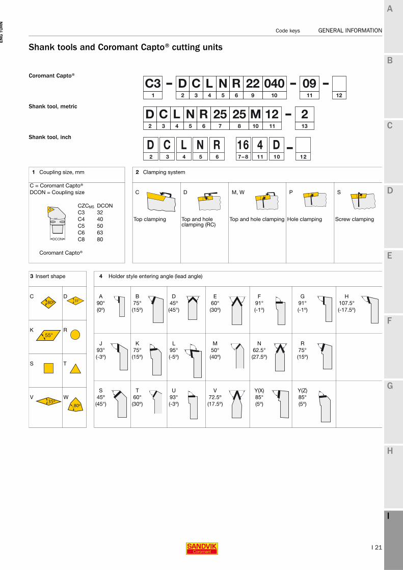
Shank tools and Coromant Capto®cutting units
Coromant Capto®
Shank tool, metric
Shank tool, inch
1 Coupling size, mm 2 Clamping system
C = Coromant Capto®DCON = Coupling size C D M, W P S
CZCMS DCONC3 32C4 40 Top clamping Top and hole
clamping (RC)Top and hole clamping Hole clamping Screw clamping
C5 50C6 63C8 80
Coromant Capto®
3 Insert shape 4 Holder style entering angle (lead angle)
C D A B D E F G H90° 75° 45º 60° 91° 91° 107.5°(0º) (15º) (45°) (30º) (-1º) (-1º) (-17.5º)
K R
J K L M N R93° 75° 95° 50° 62.5° 75°(-3º) (15º) (-5º) (40º) (27.5º) (15º)
S T
S T U V Y(X) Y(Z)V W 45º 60° 93° 72.5º 85° 85°
(45°) (30º) (-3º) (17.5º) (5º) (5º)

I 22
GENERAL INFORMATION Code keys
EN
G T
UR
N
A
B
C
D
E
F
G
H
I
GENERAL INFORMATION Code keys
5 Insert clearance angle 6 Hand of tool 7 & 8 Shank size (B, width and H, height) inch
Feed 05 = 5/16 X 5/16 85 = 1 X 1 1/4
B C R 06 = 3/8 X 3/8 86 = 1 X 1 1/2
08 = 1/2 X 1/2 20 = 1 1/4 X 1 1/4
10 = 5/8 X 5/8 24 = 1 1/2 X 1 1/2
Feed 12 = 3/4 X 3/4 32 = 2 X 2D E L 16 = 1 X 1
The seventh and eight position shall be a single significant two digit number which indicates the holders cross section. For shanks 5/8" square and over the number will represent the number of sixteenths inch of width and height.
Feed FeedN P N For shanks under 5/8" square the number of sixteenths
inch of cross section will be preceded by a zero.
Specific description
O For rectangular holders the first digit represents the number of eighths inch width, and the second digit the number of quarters inch of height.
7 & 8 Shank size (B, width and H, height) metric 9 WF dimension, Coromant Capto®
10 Tool length and width, inch
7 Shank height * Integers to be preceded by 0, e.g. H = 8 mm indicated by 08
A LF = 4"B LF= 4.5"C LF= 5"D LF = 6"E LF= 7"
8 Shank width * Integers to be preceded by 0, e.g. B = 8 mm indicated by 08
F LF= 8"M LF = 4"N LF = 4.5"
WF-dimension in mm (2 digits)
P LF = 5"R LF = 6"S LF = 7"T LF = 8"
10 Shank tool length, metric 10 Coromant Capto®tool length, metric
SANDVIK standardG LF= 5.5"
A = 32 mm N = 150 mm U LF = 5.5"B = 40 mm P = 170 mm V LF = 3.5"C = 50 mm Q = 180 mm K LF = 14"D = 60 mm R = 200 mmE = 70 mm S = 250 mmG = 80 mm T = 300 mmH = 100 mm U = 350 mm LF-dimension in mm (3
digits)J = 110 mm V = 400 mmK = 125 mm W = 400 mmL = 140 mmM = 150 mm X = Special
11 Insert size 12 Manufacturer’s option
Metric Cutting edge length Inch Inscribed circle is indicated in 1/8". When required a supplementary symbol of max 3 letters may be added to the ISO code, separated by a dash, e g W for wedge design.Cutting edge
length is indicated in mm.
1.2 = 5/321.5 = 3/161.8 = 7/322 = 1/42.5 = 5/8 13 Clamping system ceramics3 = 3/8
Integer (not rounded off).
4 = 1/2 -2 = CoroTurn®RC holders for inserts with hole5 = 5/86 = 3/4 -4 = CoroTurn®RC holders for inserts without hole8 = 110 = 1 1/4
W

I 23
Code keys GENERAL INFORMATION
EN
G T
UR
N
A
B
C
D
E
F
G
H
I
GENERAL INFORMATION Code keys
Shank tools and Coromant Capto®boring bars
Coromant Capto®
Shank tools, metric
Shank tools, inch
1 Coupling size 2 Type of bar 3 Bar diameter
mm1) inch03 = .1875
C = Coromant Capto® A = Solid steel bar with internal coolant supply. 04 = .250DCON = Coupling size 05 = .3125
06 = .375E = Carbide shank bar 08 = .500
10 = .62512 = .750
F = Dampened, carbide shank bar 16 = 1.000CZCMS DCON 20 = 1.250C3 32 24 = 1.500C4 40 S = Solid steel bar without coolant 28 = 1.750C5 50 32 = 2.000C6 63 36 = 2.250C8 80 40 = 2.500
4 Tool length, LF mm, inch 5 Clamping system
Shank toolC D M,W P S
Metric Inch Metric Inch
F = 80 3.250 S = 250 10.000 Top clamping Top and hole clamping (RC)
Top and hole clamping
Hole clamping Screw clampingH = 100 4.000 T = 300 12.000K = 125 5.000 U = 350 14.000M = 150 6.000 V = 400 15.750P = 170 6.250 W = 450 17.750Q = 180 7.250 Y = 500 20.000R = 200 8.000 X = Special
1) For metric bars DCON in mm.

I 24
GENERAL INFORMATION Code keys
EN
G T
UR
N
A
B
C
D
E
F
G
H
I
GENERAL INFORMATION Code keys
6 Insert shape 7 Bar style, lead angle (entering angle) 8 Clearance angle on major cutting edge
C D F J B C91° 93°(-1°) (-3°)
K R K L D E75° 95°(15°) (-5°)
S T P Q N O Specific description117.5° 107.5°
(-27.5°) (-17.5°)
V W U U-X P93° 93°(-3°) (-3°)
9 Hand of tool 10 Cutting edge length 11 Manufacturer´s option
Metric Inch R Cutting edge
length is indicated in mm.
1.2 = 5/32 When required a supplementary symbol of max. 3 letters may be added to the ISO code, separated by a dash, e.g.
1.5 = 3/161.8 = 7/322 = 1/4
Integer (not rounded off).
2.5 = 5/16 C = Coolant thru capabilities.3 = 3/8
L 4 = 1/2 D = Extended WF dimension, + 1.0mm (.04")5 = 5/86 = 3/4 E = Extended WF dimension, + 2.0mm (.08")8 = 110 = 1¼ F = Extended WF dimension, + 3mm (.12")
G = Altered dimensions
L = Extended LF-dimension12 Clamping system 13 Coromant Capto cutting unit size, mm
Ceramics R = Cylindrical with groove for EasyFix
ID = Clamp with pressure plate
WF x LF W = Wedge design
X = Back boring
B1 = B1 = For insert with thickness 03 = 3.18 mm (2 =1/8").Example
C4-SCLCR 11065-09WF = 11 mm (2 digits)LF = 065 mm (3 digits)
W

I 25
Code keys GENERAL INFORMATION
EN
G T
UR
N
A
B
C
D
E
F
G
H
I
GENERAL INFORMATION Code keys
CoroCut®1-2-3 edge inserts
1Hand of insert
2Main code
3Seat size
CoroCut®1-2 R 123 D G K
E H LF J M
RN CoroCut®3
T = Right hand cuttingU = Left hand cutting
L To correspond with seat size on holder.
Insert seat interchangeability:
Insert seat size Size, mm Holder Insert seat size Size, mm HolderD 1.5 D H 4.0 HE 2.0 E J 5.0 J, HF 2.5 F, E K 6.0 K, J, HG 3.0 G, F, E L 8.0 L
M 9.0 MR 15.0 R
4 Number of edges 5 Insert width 6 Front angle
1 or 2 3 E.g.: 0400 = .157 inch (4 mm) E.g.: 00 = 0°05 = 5°
7 Corner radius 8 Geometry designation
First digit: Type of operation Second digit:
E.g.: 04 = .016 inch (0.4 mm) A = Aluminium/profiling E = ER treated cutting edge
08 = .031 inch (0.8 mm) C = Cut off F = Low feed
T = Turning M = Medium feed
G = Grooving R = High feed
R = Profiling O = Optimized for special areas
B = Blank S = Sharp cutting edge
G = Blank

I 26
GENERAL INFORMATION Code keys
EN
G T
UR
N
A
B
C
D
E
F
G
H
I
GENERAL INFORMATION Code keys
CoroCut®QD
1 System 2 Application 3 Hand of insert
Q = CoroCut®QD D = Deep parting and grooving N/R/L
N = Neutral, R = Right hand, L = Left hand
4 Seat size
Insert seat size Holder seat sizeSSC mm (inch) SSCB 1.00 - 1.19 (.039 - .047) BC 1.20 - 1.49 (.047 - .059) C (B)D 1.50 - 1.99 (.059 - .078) DE 2.00 - 2.30 (.079 - .091) EF 2.31 - 2.99 (.091 - .118) F (E)G 3.00 - 3.99 (.118 - .157) G (F, E)H 4.00 - 4.99 (.157 - .196) HJ 5.00 - 5.99 (.197 - .236) JK 6.00 - 7.80 (.236 - .307) K (J)L 7.81 - 8.99 (.307 - .354) L
5 Insert width 6 Insert front angle 7 Insert corner radius
CW PSIRL, PSIRR RE
0400 = 4 mm (.157 inch) E.g.: 00 = 0° 04 = 0.40 mm (.016 inch)
8 Insert geometry
First letter Second letterC = Cut off F = Low feedT = Turning M = Medium feedB = Blank R = High feed
O = OptimizerL = Low carbonG = Blank

I 27
Code keys GENERAL INFORMATION
EN
G T
UR
N
A
B
C
D
E
F
G
H
I
GENERAL INFORMATION Code keys
CoroCut®QD
1 System 2 Application 3 Tool coupling in hand
N R L
Q = CoroCut®QD D = Deep parting and grooving
N = Neutral, R = Right hand, L = Left hand
4 Tool in hand - insert side 5 Number of insert seats
N/R/L 1 = One insertN = Neutral, R = Right hand, L = Left hand
2 = Two inserts
6 Seat size
Insert seat size
Holder seat size
SSC mm (inch) SSCB 1.00 - 1.19 (.039 - .047) BC 1.20 - 1.49 (.047 - .059) C (B)D 1.50 - 1.99 (.059 - .078) DE 2.00 - 2.30 (.079 - .091) EF 2.31 - 2.99 (.091 - .118) F (E)G 3.00 - 3.99 (.118 - .157) G (F, E)H 4.00 - 4.99 (.157 - .196) HJ 5.00 - 5.99 (.197 - .236) JK 6.00 - 7.80 (.236 - .307) K (J)L 7.81 - 8.90 (.307 - .354) L
7 Cutting depth tool 8 Through coolant
Max cutting depth, CDX C = Coolant
Metric 60 = 60 mm - = No coolant
Inch 1250 = 1.250 inch
9 Blade height 10 Front end
Cutting edge height, mm A = No or straight reinforcementD = 1 reinforcement curveD2 = 2 reinforcement curves
A D D2

I 28
GENERAL INFORMATION Code keys
EN
G T
UR
N
A
B
C
D
E
F
G
H
I
GENERAL INFORMATION Code keys
CoroCut®QD
1 Coupling 2 System 3 Application
SL Q = CoroCut®QD D = Deep parting and grooving
QS
Coromant Capto® C3-C8
4 Tool in hand 5 Holder style
N/R/L F = 0°G = 90°
N = Neutral, R = Right hand, L = Left hand
X = Other
6 Seat size
Holder seat sizeSize mm
Insert seat sizeSSC SSC
B 1.00 - 1.19 BC (B) 1.20 - 1.49 CD 1.50 - 1.99 DE 2.00 - 2.30 EF (E) 2.31 - 2.99 FG (F, E) 3.00 - 3.99 GH 4.00 - 4.99 H J 5.00 - 5.99 JK (J) 6.00 - 7.80 KL 7.81 - 8.99 L
7 Cutting depth tool 8 Through coolant
Max cutting depth, CDXC = Coolant
Metric 60 = 60 mm - = No coolant
Inch 1250 = 1.250 inch
9 Shank or coupling size/dia 10 Front end (reinforcement)
Metric Inch
Shank 4 digits 2 digits S = Swiss Designed for sliding head machines
QS 4 digits 2 digits A = No reinforcement
SL 2 digits D = Reinforced curve
I 29
Code keys GENERAL INFORMATION
EN
G T
UR
N
A
B
C
D
E
F
G
H
I
GENERAL INFORMATION Code keys
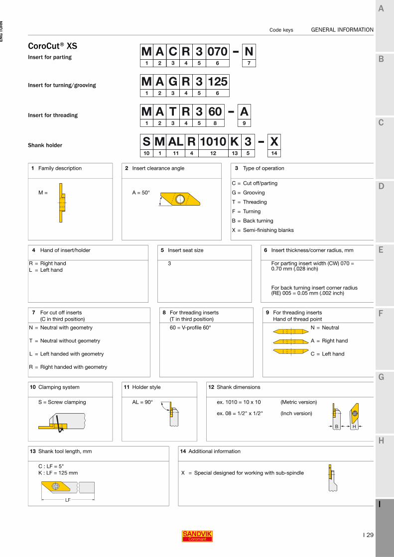
CoroCut®XSInsert for parting
Insert for turning/grooving
Insert for threading
Shank holder
1 Family description 2 Insert clearance angle 3 Type of operation
C = Cut off/parting
M = A = 50° G = Grooving
T = Threading
F = Turning
B = Back turning
X = Semi-finishing blanks
4 Hand of insert/holder 5 Insert seat size 6 Insert thickness/corner radius, mm
R = Right hand 3 For parting insert width (CW) 070 = 0.70 mm (.028 inch)L = Left hand
For back turning insert corner radius (RE) 005 = 0.05 mm (.002 inch)
7 For cut off inserts 8 For threading inserts 9 For threading inserts(C in third position) (T in third position) Hand of thread point
N = Neutral with geometry 60 = V-profile 60° N = Neutral
T = Neutral without geometry A = Right hand
L = Left handed with geometry C = Left hand
R = Right handed with geometry
10 Clamping system 11 Holder style 12 Shank dimensions
S = Screw clamping AL = 90° ex. 1010 = 10 x 10 (Metric version)
ex. 08 = 1/2" x 1/2" (Inch version)
13 Shank tool length, mm 14 Additional information
C : LF = 5"K : LF = 125 mm X = Special designed for working with sub-spindle

I 30
GENERAL INFORMATION Code keys
EN
G T
UR
N
A
B
C
D
E
F
G
H
I
GENERAL INFORMATION Code keys
CoroCut®MBInsert for turning/back boring
Insert for grooving/pre-parting
Insert for threading
Boring bars
1 Main code 2 Insert size, mm 3 Type of operation
MB = CoroCut®MB B = Back boringG = Grooving GX = Pre-parting R = Profiling full radius
4 Entering angle T = Turning(Turning) TE = Turning copying, extended f1-dimension
E.g.: 093 = 93° TH = Threading07 = 7 mm (.276 inch) FA = Face grooving A-curve09 = 9 mm (.354 inch) FB = Face grooving B-curve
5 Nose radius, RE mm 6 Insert width, CW mm 7 Pitch(Turning) (Grooving) (Threading)
mm: pitch x 100
inch: No. of threads per inch x 10 (TPI)
E.g.: 00 = Sharp E.g.: 100 = 1.00 mm (.039 inch)
02 = 0.2 mm (.008 inch)
8 Thread profile 9 Min bore diameter, DMIN 10 Penetration depth, CW(Threading) (Insert) (boring bar)
V = V profile 60°M = Metric 60°W = Whitworth 55° min. holeU = UN 60°NT = NPT 60°AC = ACME 29° Inch E.g.: Metric E.g.:SA = STUB-ACME E.g.: 10 = 10 mm (.394 inch) 06 = 0.630 inch 16 = 16 mm
08 = 0.787 inch12 = 1.260 inch
12 Hand of insert 14 Bar dia, DCON inch 15 Shank type
R = Right hand style R = Cylindrical
L = Left hand style No symbol = With flats
13 Type of bar 16 Geometry
A = Steel bar with internal coolant supply Inch - = Without chip forming geometry0625 = .625 inch
E = Carbide shank bar Metric A = Chip forming geometry16 = 16 mm

I 31
Code keys GENERAL INFORMATION
EN
G T
UR
N
A
B
C
D
E
F
G
H
I
GENERAL INFORMATION Code keys
CoroCut®holdersCoromant Capto®
Shank holder
Blade
Metric
Inch
1 Coupling size 2 Hand of tool 3 Holder style
C = Coromant Capto® R F G XDCON = Coupling size
DCONmm Inch
C3 32 (1.260) 0° 90° 1-70°C4 40 (1.575) NC5 50 (1.968)C6 63 (2.480)C8 80 (3.150) 4 Main code
L
123
5 Insert seat size 6 Machining limitations
CoroCut®1-2 D G KE H LF J M
RCoroCut®3 T = Right hand cutting
U = Left hand cutting
To correspond with seat size on insert.
Max cutting depth, CDX in mm
Metric 08 = 8 mmInch 059 = .590 inch
8 Clamping system 9 Number of insert seats 10 Holder angle
A B C D 007 = 7°Spring clamp Screw clamp Shallow grooving Screw clamp
reinforced1 One insert seat 045 = 45°
070 = 70°2 Two insert seats
Valid for holder style = X
11 Special application 12 Min. diameter for first cut, for face grooving
13 Type of curve, for face grooving
S = Holder for small part machines Min. diameter for first cut in mm.
B = B curve A = A curve
7 Shank/cutting unit dimension
Coromant Capto® Shank toolInch Shank size in 1/16 inch
eg. 08 = 8/16 = 1/2 inch
H x B08
MetricIntegers to be preceded by 0, e.g. b = 8 mm indicated by 08
For example:W LF27 mm 55 mm Blade1.063 inch 2.165 inch Dimensions in mm. H B
16 16

I 32
GENERAL INFORMATION Code keys
EN
G T
UR
N
A
B
C
D
E
F
G
H
I
GENERAL INFORMATION Code keys
CoroThread®266
1 Main code 2 Hand of tool 3 Type of machining 4 Insert size/dimension
266 = CoroThread 266 R = Right hand style G = Inserts for external threading 16 = iC 3/8'' = 9.52 mm22 = iC 1/2'' = 12.70 mm
L = Left hand style L = Inserts for internal threading 27 = iC 5/8'' = 15.88 mm
5 Thread profile 6 Number of points per cutting edge
VM0 = V-profile 60° AC0 = ACME 29° Varies from 1 to 3 points.VW0 = V-Profile 55° SA0 = STUB-ACME 29°MM0 = Metric 60°? NJ0 = UNJ 60° 1 = 1 pointUN0 = UN 60° MJ0 = MJ 60° 2 = 2 pointsWH0 = Whitworth 55° NF0 = NPTF 60° 3 = 3 pointsNT0 = NPT 60°? BU0 = ButtressRN0 = Round 30°? RD0 = API Rd 60°PT0 = BSPT 55° V38 = V-0.038R TR0 = Trapezoidal 30° V40 = V-0.040 AB0 = Buttress 45°-7° V50 = V-0.050
7 Cutting edge condition 8 Pitch 9 Supplementary code
A = Edge rounded (ER) mm: pitch x 100 Taper on diameter/inch per foot (i.p.f.)F = Sharp cutting edge Inch: number of threads per inch x 10 1 = 1 i.p.f.C = Chip forming geometry 2 = 2 i.p.f.
3 = 3 i.p.f.
10 Tolerance of cutting edge position
M = ± 0.05 mm (.002 inch) axialE = ± 0.01 mm (.0004 inch) axial
11 Cubic boron nitride inserts
E = Edge rounded (ER)
1) Marking:All inserts are marked with the profile, grade and pitch: internal inserts being identified with a circle. To prevent erasure, the marking is laser cut on the side of the inserts.
External right hand insertsInternal left hand inserts
External left hand insertsInternal right hand inserts

I 33
Code keys GENERAL INFORMATION
EN
G T
UR
N
A
B
C
D
E
F
G
H
I
GENERAL INFORMATION Code keys
CoroThread®266
Shank holders, inch
Boring bar, inch
Coromant Capto cutting unit
Shank holders, metric
Boring bar, metric
CoroThread® 266 SL cutting head
Cartridge
1 Main code 2 Hand of tool 3 Insert size/dimension
266 = CoroThread 266 R = Right hand style Shank holders254 = CoroThread 254 L = Left hand style Inch Metric
3 = 3/8" = iC 16 = iC 3/8'' = 9.52 mm4 = 1/2" = iC 22 = iC 1/2'' = 12.70 mm5 = 5/8" = iC 27 = iC 5/8'' = 15.88 mm
4 Type of tool and holder style 5 Holder for upside down mounting
External InternalZ = Drop head design for upside down
mountingFeed direction
Feed direction
FA FG KF
6 Shank dimension 7 Type of shank
External InternalInch Inch Shank size Shank diameter R = Round shank16 = 1 x 1" D12 = .750" D24 = 1.500"20 = 1 1/4 x 1 1/4" D16 = 1.000" D32 = 2.000"24 = 1 1/2 x 1 1/2" D20 = 1.250"Metric MetricShank size H x B Shank diameter, DCON
8 Type of bar 9 Coromant Capto®size 10 WF dimension, mm 11 Tool length, LF-dimension, mm
E = Carbide shank bar C = Coromant Capto DCON = size code
C3 DCON = 32 mmC4 DCON = 40 mmC5 DCON = 50 mmC6 DCON = 63 mm MetricC8 DCON = 80 mm LF-dimension in mm
12 Cutting unit 13 SL coupling size 14 Cutting edge height, HF mm 15 Type of tool
SL-System DCON - dimension (coupling dia.)C = Cartridge
16 Type of design
A = letter for alternative designs according to ISO 5611.

I 34
GENERAL INFORMATION Code keys
EN
G T
UR
N
A
B
C
D
E
F
G
H
I
GENERAL INFORMATION Code keys
T-Max®Twin-Lock
T-Max Twin-Lock®holders
1 Hand of tool 2 Main code
R = Right hand style 166.39 = Twin-Lock®shank holder466.39 = Twin-Lock®cartridge566.39 = Twin-Lock®SL cutting head
3 Type of tool and holder style 4 Tool holder dimensions, mm 5 Insert dimension, mm
External Shank tool Insert size L, in mmH x B L = 24.0 mm (.945 inch)
Feed direction
T-Max Twin-Lock®SL cutting headDCON x LF x WF
FGInternal
CartridgeHF x WF
Feed direction
KF
T-Max Twin-Lock®inserts
1 Hand of insert 2 Main code 3 Type of machining 4 Insert dimension
R = Right hand style insert 166.39 = T-Max®Twin-Lock G = Inserts for external threading Length L, in mmL = 24.0 mm (.945 inch)
L = Inserts for internal threading
5 Thread profile 6 Number of points per cutting edge 7 Pitch
RD0 = API Round Vee tubing and casing Varies from 2 to 4 points. Number of threads per inch x 10
RD1 = API Round Vee tubing and casing
BU1 = API Buttress =13 3/8'' (3/4'' i.p.f)
BU2 = API Buttress= 16'' (1''i.p.f)

I 35
Code keys GENERAL INFORMATION
EN
G T
UR
N
A
B
C
D
E
F
G
H
I
GENERAL INFORMATION Code keys
CoroPlex™ TT
1 Coupling size mm, inch 2 3 and 7 4 and 8Type of tool Clamping system Insert shape
C = Coromant Capto® T = Twin toolDCON = Coupling size D C
C3 DCON = 32 (1.260)C4 DCON = 40 (1.575)C5 DCON = 50 (1.969) Top and hole clamping (RC)
C6 DCON = 63 (2.480) CoroTurn®RC
C8 DCON = 80 (3.150) D
5 and 9 6 and 10 11 Hand of tool 12 Tool length, LF mmHolder style Cutting edge length,L mm
L M R Feed95° 50°(-5°) (40°)
Entering angle (Lead angle) L Feed
N Feed Feed
I 36
GENERAL INFORMATION Code keys
EN
G T
UR
N
A
B
C
D
E
F
G
H
I
GENERAL INFORMATION Code keys
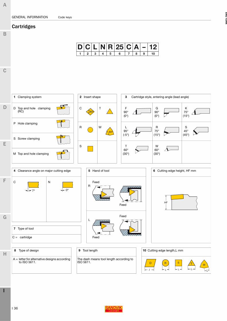
Cartridges
1 Clamping system 2 Insert shape 3 Cartridge style, entering angle (lead angle)
D Top and hole clamping (RC)
C T F G K90° 90° 75°(0°) (0°) (15°)
P Hole clampingR W L R S
95° 75° 45°(-5°) (15°) (45°)
S Screw clamping
S T W60° 60°
M Top and hole clamping (30°) (30°)
4 Clearance angle on major cutting edge 5 Hand of tool 6 Cutting edge height, HF mm
C N FeedR
Feed
FeedL
7 Type of tool
C = cartridge Feed
8 Type of design 9 Tool length 10 Cutting edge length,L mm
A = letter for alternative designs according to ISO 5611.
The dash means tool length according to ISO 5611.
W

I 37
Code keys GENERAL INFORMATION
EN
G T
UR
N
A
B
C
D
E
F
G
H
I
GENERAL INFORMATION Code keys
Machine adapted clamping units
1 Coromant Capto®size
C4-40mm, C5-50mm
2 Application
T-TurningD-Driven
3 Hand of clamping units
L - LeftR - RightN - Neutral
4 Type of operation
E – External (OD)I - Internal (face/ID)
5 Machine
MZ – MazakMS - Mori SeikiNA - NakamuraOK - OkumaBT - Bolt on turret (Doosan)GM - GildemeisterMA - Murata
6 Turret hole dia (mm)
40, 50, 55, 60, 65, 68, 75, 85, 110
7 Turret interface version
A, B, CV = VDI style
8 Configuration
= for normal single clamping unit
DT = for main spindle and subspindle (two clamping units in one holder)
ET = extended
DE = extended for main spindle and subspindle (two clamping units in one holder)
TT = for machine with half index turret (two clamping units in one holder)
YT = for machines with “Y” axis (two clamping units in one holder)
DY = for machines with ”Y” axis (four clamping units in one holder)
SS = for subspindle
SP = short projection
XT = two clamping units in one holder (change tools with X axis)
9 Coolant supply (driven tools only)
I – Internal and external (80bars)
E – External only
I 38
GENERAL INFORMATION Coolant supply information
EN
G T
UR
N
A
B
C
D
E
F
G
H
I
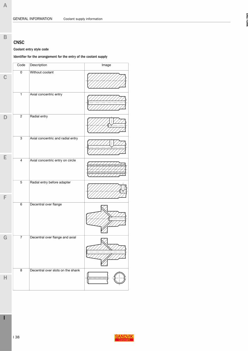
GENERAL INFORMATION Coolant supply information
CNSCCoolant entry style code
Identifier for the arrangement for the entry of the coolant supply
Code Description Image
0 Without coolant
1 Axial concentric entry
2 Radial entry
3 Axial concentric and radial entry
4 Axial concentric entry on circle
5 Radial entry before adapter
6 Decentral over flange
7 Decentral over flange and axial
8 Decentral over slots on the shank

I 39
Coolant supply information GENERAL INFORMATION
EN
G T
UR
N
A
B
C
D
E
F
G
H
I
GENERAL INFORMATION Coolant supply information
CXSCCoolant exit style code
Identifier for the arrangement for the exit of the coolant supply
Code Description Image
0 No coolant exit
1 Axial concentric exit
2 Radial exit
3 Axial inclined exit
4 Axial concentric on circle
5 Axial inclined exit with nozzle, adjustable
6 Decentral exit with nozzle, adjustable
7 Decentral over slots on the shank
8 Axial or decentral with nozzle, adjustable

I 40
GENERAL INFORMATION Alphanumeric index
EN
G
A
B
C
D
E
F
G
H
I
Code Page Code Page Code Page131..-B H9131-A..-B H9132L..-B H3-H4132N H7132P..-B H5132W..-B H6151.2 F27175.32 A94190.1 A98254R/LG B152254R/LKF B153266LG..AC..F C33266LG..MJ..A C29266LG..MM..A C12266LG..NT..A C22266LG..PT..A C24266LG..RN..A C27266LG..SA..F C35266LG..TR..F C31266LG..UN..A C16266LG..VM..A C6266LG..VW..A C8266LG..WH..A C20266LL..AC..F C34266LL..MM..A C14266LL..NT..A C23266LL..PT..A C25266LL..RN..A C28266LL..SA..A C36266LL..TR..F C32266LL..UN..A C18266LL..VM..A C7266LL..VW..A C9266LL..WH..A C21266R/LFA C48266R/LFG C46-C47266R/LG-BG C40266R/LKF C52266R/LKF..CA E23266R/LKF-R C53266RG..AC C33266RG..BU C39266RG..MJ C29266RG..MM C10-C11266RG..NF C26266RG..NJ C30266RG..NT C22266RG..PT C24266RG..RD C38266RG..RN C27266RG..SA C35266RG..TR C31266RG..UN C15266RG..V38 C37266RG..V40 C37266RG..V50 C37266RG..VM C6266RG..VW C8266RG..WH C19266RL..AC C34266RL..BU C39266RL..MM C13266RL..NF C26266RL..NT C23266RL..PT C25266RL..RD C38266RL..RN C28266RL..SA C36266RL..TR..F C32266RL..UN C17266RL..V38 C37266RL..V40 C37266RL..V50 C37266RL..VM C7266RL..VW C9266RL..WH C21392.410..ASHR/L G56392.419..APBR/L..HP G58392.419..ASHA G55392.419..ASHR/L G54392.419..ASHR/L..HP G54392.T..SL70R/L G53392.T..SLR/L G52392.T63-131 G57392.T63-2C G51393.SBB H8
5692 H175693 H16570 (RED) G89570..580-80 G98570-2C G65-G66570-2C..CR G67570-3C G69-G70570-3C (QC) G74570-3C..CR G71-G72570-3C..CR (QC) G77570-3C..R/L (QC) G75-G76570-4 G95570-4C G73570-80 (QC - RED) G92570-80 G97570-80 200R/L G88570-80 23-40R/L G91570C-SVUBR/L A472570-DCLNR/L A227570-DCLNR/L-80 A228570-DDUNR/L A230570-DDUNR/L..X A241570-DDUNR/L-80 A232570-DDUNR/L-80..X A242570-DDXNR/L A231570-DDXNR/L-80 A233570-DSKNR/L A234570-DSKNR/L-80 A235570-DTFNR/L A237570-DTFNR/L-80 A238570-DVUNR/L A239570-DVUNR/L..X A243570-DVUNR/L-80..X A244570-DWLNR/L A240570-M G96570-SCLCR/L A455570-SCLPR/L A512570-SDUCR/L A461570-SDUCR/L..X A479570-SDUCR/L-80 A464570-SDUPR/L A513570-SDUPR/L..X A517570-SDXCR/L A460570-SDXPR/L A514570-STFCR/L A468570-STFPR/L A515570-SVLBR/L A471570-SVLBR/L-80 A476570-SVPBR/L A471570-SVQCR/L A474570-SVUCR/L A473570-SVUCR/L..X A480570-SWLPR/L A516570-xxNG G62570-xxR/L123 B67-B74570-xxR/L123T B122570-xxR/L123U B122570-xxR/L151.3 B147570-xxR/L151.3..A B141570-xxR/L151.3..B B142570-xxR/LF G61570-xxR/LSMAL B133
AA..DCLNR/L A208A..DDUNR/L A211A..DSKNR/L A214A..DTFNR/L A217A..DVUNR/L A220A..DWLNR/L A223A..MWLNR/L A224A..PCLNR/L A209A..PCLNR/L..HP A207A..PDUNR/L A212A..PDUNR/L..HP A210A..PSKNR/L A215A..PSKNR/L..HP A213A..PTFNR/L A218A..PTFNR/L..HP A216A..PWLNR/L..HP A222A..SCLCR/L A403-A404A..SCLCR/L..HP A401-A402A..SCLPR/L A490-A491A..SDQCR/L A412-A415A..SDQCR/L..HP A407-A408A..SDUCR/L A409-A410
A..SDUCR/L..HP A405-A406A..SDUCR/L..X A436-A440A..SDUPR/L A492-A494A..SDUPR/L..X A499-A500A..SDXCR/L A412-A415A..SDXPR/L A493-A494A..SRDDN A416A..SRXDR/L A416A..SSKCR/L A417A..STFCR/L A420-A422A..STFCR/L..HP A418-A419A..STFPR/L A495-A496A..STUCR/L A423A..SVPBR/L A434A..SVPBR/L..HP A428-A429A..SVQBR/L A432-A435A..SVQBR/L..HP A426-A427A..SVQCR/L A430-A431A..SVUBR/L A432-A433A..SVUBR/L (SPM) A390A..SVUBR/L..HP A424-A425A..SVUCR/L A430-A431A..SWLPR/L A497-A498A393.SBB H8A-393.SBB..MZ F69A570-2C G65-G67A570-3C G69-G72A570-3C (QC) G74-G76A570-4C G73ABB-TNI-CDI80 F41APBA-R/L-VDI..HP F24APBR/L-VDI..HP F23APB-TNE-BT65A F46APB-TNE-CDI80 F39APB-TNE-MS40A F80APB-TNE-MS60A F80APB-TNE-MZ68A F63APB-TNE-OK60A F98ASHA-R/L-VDI..HP F22ASHR/L-VDI..HP F21ASH-TNE-CDI80 F38
BBA-R/LGC F26BP B149BPGN B151BPGR/L B151BPR/L B150
CC10-APBA G47C10-APBR/L G48C10-R/LC2095 F34CCBNR/L A267CCET-UM A293CCGT-UM A293CCGW A296CCGX-AL A293-A296CCLNR/L A268CCMT-KF A291CCMT-KM A293CCMT-KR A294CCMT-MF A291CCMT-MM A292CCMT-MMC A292CCMT-MR A294CCMT-PF A291CCMT-PM A292CCMT-PMC A292CCMT-PR A294CCMT-SMC A292CCMT-UF A291CCMT-UM A293CCMT-UR A294CCMT-WF A291CCMT-WM A292CCMT-XF A291CCMT-XH A295CCMT-XM A293CCMT-XR A294CCMW A294-A296CCRNR/L A268CDJNR/L A270CDNNN A270CDNNR/L A270CKJNR/L A284
GENERAL INFORMATION Alphanumeric index

I 41
Alphanumeric index GENERAL INFORMATION
EN
G
A
B
C
D
E
F
G
H
I
CNGA A52-A54CNGG-SGF A45CNGN A245CNGQ A54CNGX A52-A54CNMA-KR A50CNMG-HM A47CNMG-KF A44CNMG-KM A47CNMG-KR A50CNMG-KRR A49CNMG-LC A44CNMG-MF A44CNMG-MM A47CNMG-MMC A45CNMG-MR A50-A51CNMG-MRR A48CNMG-PF A44CNMG-PM A46CNMG-PMC A46CNMG-PR A49CNMG-QM A47CNMG-SF A45CNMG-SM A47CNMG-SMC A46CNMG-SMR A48-A51CNMG-WF A44CNMG-WL A45CNMG-WM A46CNMG-WMX A46CNMG-XF A45CNMG-XM A48CNMG-XMR A51CNMM-HR A50CNMM-MR A49CNMM-PR A49CNMM-QR A50CNMM-WR A49CNMU-KM A48CNMU-KR A51CNMU-PF A45CNMU-PM A48CNMU-PR A51CNMU-QM A48CNMX-PF A96CNMX-SM A55CPMT-KF A483CPMT-KM A483CPMT-MF A483CPMT-MM A483CPMT-PF A483CPMT-PM A483CPMT-UM A484CRDCN A272CRDCR/L A272CRDNN A273CRSNR/L A273-A274CSDNN A274-A276CSKNR/L A274-A276CSRNR/L A274-A276CSSNR/L A275-A277CTGNR/L A282CU-3C..-Cx G68Cx-131 G42-G43Cx-151.2 G49Cx-266R/LFA C43Cx-266R/LFG C42Cx-266R/LKF C50-C51Cx-266RS..HP C41Cx-391.01 G3-G4Cx-391.02 G5-G8Cx-4-SL..AX G18Cx-570..NG G11Cx-570..R/LF G10Cx-570..R/LF-T G15Cx-570..R/LG G12-G13Cx-570..R/LX G14-G17Cx-570..RG-040-MS G13Cx-570-2C G23-G25Cx-570-3C G27-G30Cx-570-3C80 G33Cx-570-4C G31Cx-APBA G47Cx-APBA..HP G46Cx-APBR/L..HP G45Cx-ASHA G37-G38
Cx-ASHA..HP G36Cx-ASHR/L G35Cx-ASHR/L..HP G34Cx-ASHR/L3 G41Cx-ASHR/L45 G40Cx-ASHS G39Cx-CCLNR/L A254Cx-CCRNR/L A254Cx-CDJNR/L A256Cx-CRDCN A258Cx-CRSCR/L A258Cx-CRSNR/L A259Cx-CSDNN A260Cx-CSKNR/L A260Cx-CSRNR/L A260Cx-CSSNR/L A261Cx-CTGNR/L A265Cx-CXS G44Cx-DCKNR/L A108Cx-DCLNR/L A106Cx-DCLNR/L (INT) A192Cx-DCLNR/L..-2 A255Cx-DCMNN A105Cx-DCRNR/L A107Cx-DCRNR/L..-2 A255Cx-DDHNR/L A116Cx-DDJNR/L A116Cx-DDJNR/L..-2 A257Cx-DDMNR/L A114-A115Cx-DDNNN A117Cx-DDUNR/L A118Cx-DDUNR/L (INT) A195Cx-DNE80 F42Cx-DNE-BT F50Cx-DNE-GM F56Cx-DNE-MS F86Cx-DNE-MZ F70-F71Cx-DNE-MZ..X F72Cx-DNE-MZ-F F73Cx-DNE-NA F92Cx-DNE-OK F103Cx-DNI80 F42Cx-DNI-BT F51Cx-DNI-GM F57Cx-DNI-MS F87Cx-DNI-MZ F76Cx-DNI-MZ..V F74Cx-DNI-MZ..X F74Cx-DNI-MZ-F F75Cx-DNI-NA F93Cx-DNI-OK F104Cx-DRSNR/L A120Cx-DSDNN A127Cx-DSDNN..-2 A262Cx-DSKNR/L A128Cx-DSKNR/L..-2 A263Cx-DSRNR/L A128Cx-DSRNR/L..-2 A263Cx-DSSNR/L A129Cx-DSSNR/L..-2 A264Cx-DTFNR/L A135Cx-DTFNR/L (INT) A200Cx-DTGNR/L A134Cx-DTGNR/L..-2 A266Cx-DTJNR/L A134Cx-DTTNR/L A135Cx-DVJNR/L A138Cx-DVMNR/L A114Cx-DVVNN A138Cx-DWLNR/L A140Cx-DWLNR/L (INT) A205Cx-MTJNR/L A137Cx-MVJNR/L A139Cx-MVUNR/L (INT) A203Cx-MWLNR/L A141Cx-MWLNR/L (INT) A206Cx-NC2000 F30Cx-NC3000 F31Cx-NC3000-V F20Cx-NC5010 F35Cx-NR G50Cx-PCLNR/L A109Cx-PCLNR/L (INT) A193Cx-PCLNR/L..HP A102Cx-PCLNR/L..HP (INT) A191Cx-PCLNR/L..HP A104
Cx-PCMNN..HP A104Cx-PCRNR/L A109Cx-PCRNR/L..HP A103Cx-PDJNR/L A119Cx-PDJNR/L..HP A110-A112Cx-PDMNR/L..HP A110-A113Cx-PDUNR/L (INT) A196Cx-PDUNR/L..HP A111Cx-PDUNR/L..HP (INT) A194Cx-PLRNR/L A142Cx-PLTNR/L A142Cx-PRDCN A121Cx-PRSCR/L A121Cx-PSDNN A133Cx-PSDNN..HP A124Cx-PSKNR/L A130Cx-PSKNR/L (INT) A198Cx-PSKNR/L..HP A123Cx-PSKNR/L..HP (INT) A197Cx-PSRNR/L A131Cx-PSRNR/L..HP A122Cx-PSSNR/L A132Cx-PSSNR/L..HP A125-A126Cx-PTFNR/L A202Cx-PTFNR/L (INT) A201Cx-PTFNR/L..HP (INT) A199Cx-PTGNR/L A136Cx-PWLNR/L..HP (INT) A204Cx-R/L166.0KF C62Cx-R/LC F25Cx-R/LC2080 F29Cx-R/LC2085 F28Cx-R/LC2090 F33Cx-R/LC2095 F34Cx-R/LC20x5 F32Cx-R/LC20xxA F19Cx-R/LC20xxS F18Cx-R/LCE80 F36-F37Cx-R/LCI80 F40Cx-R/L-Cx-R/L G7Cx-R/LF123 B38-B41Cx-R/LF123T/U B118CXS..F..AR/L B162CXS..FN G59CXS..R/L G60CXS-A G80-G84Cx-SCLCR/L A323Cx-SCLCR/L (INT) A392Cx-SCLCR/L..HP A391CX-SCLCR/L..HPA A322Cx-SCMCN A324Cx-SDJCR/L A326CX-SDJCR/L..HPA A325Cx-SDNCN A326Cx-SDUCR/L A394Cx-SDUCR/L..HP A393Cx-SDUCR/L..X A400Cx-SL..-R/LF G9Cx-SL2C G26Cx-SL3C G30Cx-SL3C..CR G32Cx-SL70-R/L G19-G22Cx-SRDCN A330-A331Cx-SRDCN..HPA A328Cx-SRSCR/L A332Cx-SRSCR/L..HP A327Cx-SRSCR/L..HPA A329Cx-SSDBN A334Cx-SSDCN A333Cx-SSKCR/L A395Cx-SSRBR/L A334Cx-SSRCR/L A333Cx-SSTBR/L A335Cx-STFCR/L A397Cx-STFCR/L..HP A396Cx-STGCR/L A336Cx-STJCR/L A336Cx-SVHBR/L A342Cx-SVHBR/L..HPA A338Cx-SVJBR/L A342Cx-SVJBR/L..HP A337Cx-SVJBR/L..HPA A340Cx-SVMBR/L A344-A345Cx-SVMBR/L..HP A341Cx-SVQBR/L A399Cx-SVQBR/L..HP A398
Code Page Code Page Code Page
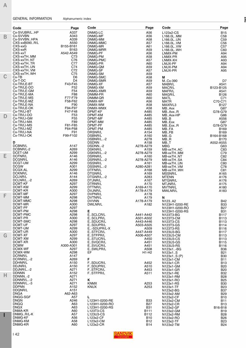
I 42
GENERAL INFORMATION Alphanumeric index
EN
G
A
B
C
D
E
F
G
H
I
Cx-SVUBR/L..HP A337Cx-SVVBN A343Cx-SVVBN..HPA A339CXS-xxB090..R/L A550CXS-xxG B155-B161CXS-xxR B163CXS-xxT A542-A549CXS-xxTH..MM C73CXS-xxTH..NT C76CXS-xxTH..TR C77CXS-xxTH..UN C74CXS-xxTH..VM C72CXS-xxTH..WH C75Cx-TB D6Cx-T-DC D4Cx-TR/LE-BT F43-F45Cx-TR/LE-DO F52Cx-TR/LE-GM F54Cx-TR/LE-MA F88Cx-TR/LE-MS F77-F79Cx-TR/LE-MZ F58-F62Cx-TR/LE-NA F90Cx-TR/LE-OK F94-F97Cx-TR/LI-BT F47-F48Cx-TR/LI-DO F53Cx-TR/LI-GM F55Cx-TR/LI-MA F89Cx-TR/LI-MS F81-F85Cx-TR/LI-MZ F64-F68Cx-TR/LI-NA F91Cx-TR/LI-OK F99-F102
DDCBNR/L A147DCBNR/L-2 A269DCET-UM A299DCFNR/L A146DCGNR/L A146DCGT-UM A299DCGW A301DCGX-AL A299DCKNR/L A146DCLNR/L A144DCLNR/L..-2 A269DCMT-KF A297DCMT-KM A299DCMT-KR A300DCMT-MF A297DCMT-MM A298DCMT-MMC A298DCMT-MR A300DCMT-PF A297DCMT-PM A298DCMT-PMC A298DCMT-PR A300DCMT-SMC A298DCMT-UF A297DCMT-UM A299DCMT-UR A300DCMT-XF A297DCMT-XM A299DCMT-XR A300DCMW A300-A301DCMX-WF A297DCMX-WM A298DCRNR/L A147DCRNR/L..-2 A269DDHNR/L A150DDJNR/L A150DDJNR/L..-2 A271DDNNN A152DDNNN..-2 A271DDNNR/L..-2 A271DDNNR/L..-3 A271DDPNN A152DDQNR/L A151DNGA A62-A63DNGG-SGF A57DNGN A246DNGQ A63DNGX A63DNMA-KR A60DNMG..R/L-K A57DNMG-KF A56DNMG-KM A58DNMG-KR A60
DNMG-LC A56DNMG-MF A56DNMG-MM A58DNMG-MMC A57DNMG-MR A61DNMG-MRR A59DNMG-PF A56DNMG-PM A58DNMG-PMC A57DNMG-PR A60DNMG-QM A59DNMG-SF A57DNMG-SM A59DNMG-SMC A58DNMG-SMR A59DNMG-XF A57DNMG-XM A59DNMG-XMR A59DNMM-PR A60DNMM-QR A60DNMX-WF A56DNMX-WM A58DNMX-WMX A58DPMT-KF A485DPMT-KM A485DPMT-MF A485DPMT-MM A485DPMT-PF A485DPMT-PM A485DRSNR/L A154DSBNR/L A160DSBNR/L..-2 A278DSDNN A158DSDNN..-2 A278-A279DSKNR/L A159DSKNR/L..-2 A278-A279DSRNR/L A160DSRNR/L..-2 A278-A279DSSNR/L A161DSSNR/L..-2 A280-A281DTFNR/L A168DTGNR/L A169DTGNR/L..-2 A283DTJNR/L A167DTRNR/L A170DTTNR/L A169-A170DVJNR/L A178-A179DVPNR/L A178DVTNR/L A179DVVNN A178-A179DWLNR/L A182
EE..SCLCR/L A441-A442E..SCLPR/L A501-A502E..SDUCR/L A443-A446E..SDUPR/L A503-A505E..-SDUPR/L-X A509E..STFCR/L A447-A449E..STFPR/L A506-A507E..STUCR/L A450E..SVQCR/L A451E..SVUCR/L A451E..SWLPR/L A508EF H1-H2
FF..SDUCR/L A452F..SDUPR/L A510F..STFCR/L A453F..STFPR/L A511
KKNMX A253KNUX A253
LL123H1-0200-RE B33L123H1-0200-RO B27L123H1-0200-RS B31L123T3-CS B111L123U3-CS B112L123x2-CF B10L123x2-CM B12L123x2-CR B14
L123x2-CS B15L166.0L..MM C58L166.0L..UN C59L166.0L..VM C56L166.0L..VW C57L166.0L..WH C60LNMX-PM A94LNMX-PR A95LNMX-XH A93LNUX-PF A94LNUX-PM A94LNUX-PR A95
MM..Cx-390 D7MABR/L A541MACR/L B123-B125MAFR/L A541MAGR/L B126MATL C71MATR C70-C71MAXR/L3 B127MB..Axx G87MB..Axx..R G78-G79MB..Axx-HP G86MB..B A556MB..Exx G87MB..Exx..R G78-G79MB..FA B169MB..FB B169MB..G B164-B168MB..R B170MB..T A552-A555MBG G63MB-xxTH..AC C83MB-xxTH..MM C79MB-xxTH..NT C82MB-xxTH..SA C84MB-xxTH..UN C80MB-xxTH..VM C78MB-xxTH..WH C81MSSNR/L A165MTENN A176MTGNR/L A176MTJNR/L A175MVTNR/L A180MWLNR/L A183
NN123..A2 B42N123H1-0200-RE B33N123H1-0200-RO B27N123H1-0200-RS B31N123T3-BG B117N123T3-CM B113N123T3-CS B113N123T3-GS B114N123T3-RS B116N123U3-BG B117N123U3-CM B113N123U3-CS B113N123U3-GS B115N123U3-RS B116N123x1..-BG B36N123x1..S B21N123x1..S (P) B30N123x1-CM B11N123x1-CR B13N123x1-GM B20N123x1-GR B20N123x1-RE B32N123x1-RM B28N123x1-RO B25N123x1-RS B30N123x1-TF B23N123x2-BG B37N123x2-AM B29N123x2-CF B10N123x2-CM B11N123x2-CR B13N123x2-GF B16-B18N123x2-GM B19N123x2-RM B28N123x2-RO B26N123x2-TF B23N123x2-TM B24
Code Page Code Page Code Page
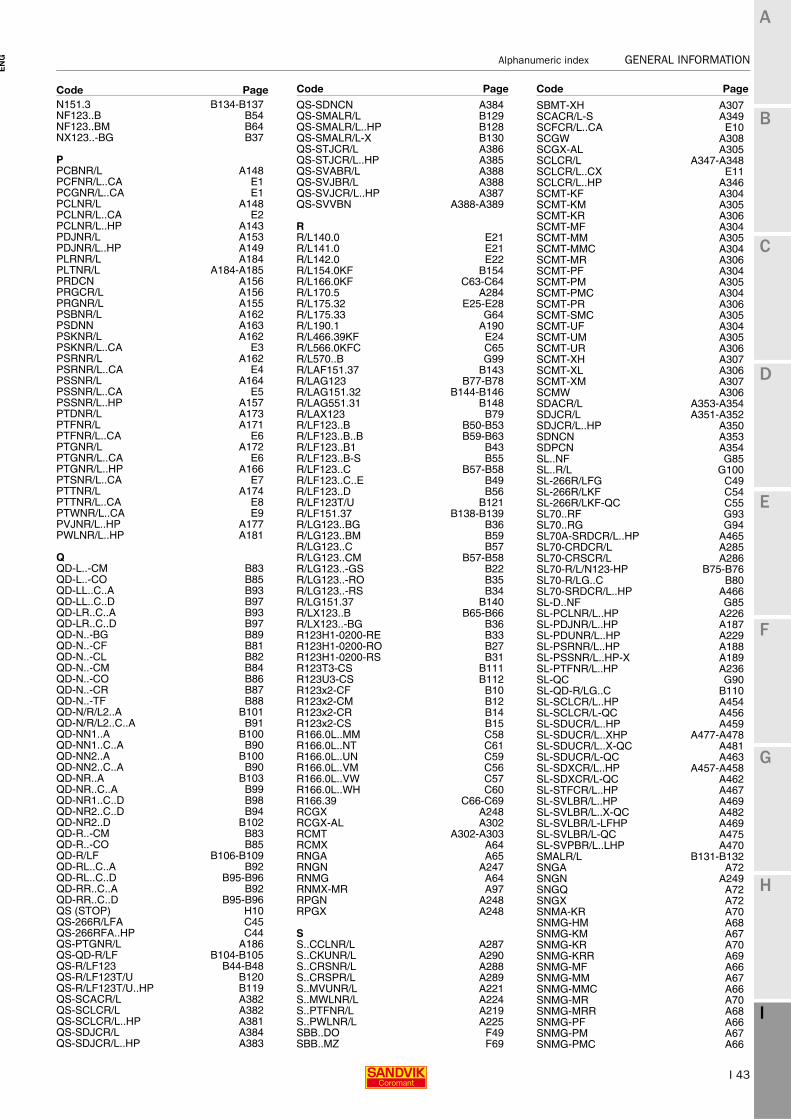
I 43
Alphanumeric index GENERAL INFORMATION
EN
G
A
B
C
D
E
F
G
H
I
N151.3 B134-B137NF123..B B54NF123..BM B64NX123..-BG B37
PPCBNR/L A148PCFNR/L..CA E1PCGNR/L..CA E1PCLNR/L A148PCLNR/L..CA E2PCLNR/L..HP A143PDJNR/L A153PDJNR/L..HP A149PLRNR/L A184PLTNR/L A184-A185PRDCN A156PRGCR/L A156PRGNR/L A155PSBNR/L A162PSDNN A163PSKNR/L A162PSKNR/L..CA E3PSRNR/L A162PSRNR/L..CA E4PSSNR/L A164PSSNR/L..CA E5PSSNR/L..HP A157PTDNR/L A173PTFNR/L A171PTFNR/L..CA E6PTGNR/L A172PTGNR/L..CA E6PTGNR/L..HP A166PTSNR/L..CA E7PTTNR/L A174PTTNR/L..CA E8PTWNR/L..CA E9PVJNR/L..HP A177PWLNR/L..HP A181
QQD-L..-CM B83QD-L..-CO B85QD-LL..C..A B93QD-LL..C..D B97QD-LR..C..A B93QD-LR..C..D B97QD-N..-BG B89QD-N..-CF B81QD-N..-CL B82QD-N..-CM B84QD-N..-CO B86QD-N..-CR B87QD-N..-TF B88QD-N/R/L2..A B101QD-N/R/L2..C..A B91QD-NN1..A B100QD-NN1..C..A B90QD-NN2..A B100QD-NN2..C..A B90QD-NR..A B103QD-NR..C..A B99QD-NR1..C..D B98QD-NR2..C..D B94QD-NR2..D B102QD-R..-CM B83QD-R..-CO B85QD-R/LF B106-B109QD-RL..C..A B92QD-RL..C..D B95-B96QD-RR..C..A B92QD-RR..C..D B95-B96QS (STOP) H10QS-266R/LFA C45QS-266RFA..HP C44QS-PTGNR/L A186QS-QD-R/LF B104-B105QS-R/LF123 B44-B48QS-R/LF123T/U B120QS-R/LF123T/U..HP B119QS-SCACR/L A382QS-SCLCR/L A382QS-SCLCR/L..HP A381QS-SDJCR/L A384QS-SDJCR/L..HP A383
QS-SDNCN A384QS-SMALR/L B129QS-SMALR/L..HP B128QS-SMALR/L-X B130QS-STJCR/L A386QS-STJCR/L..HP A385QS-SVABR/L A388QS-SVJBR/L A388QS-SVJCR/L..HP A387QS-SVVBN A388-A389
RR/L140.0 E21R/L141.0 E21R/L142.0 E22R/L154.0KF B154R/L166.0KF C63-C64R/L170.5 A284R/L175.32 E25-E28R/L175.33 G64R/L190.1 A190R/L466.39KF E24R/L566.0KFC C65R/L570..B G99R/LAF151.37 B143R/LAG123 B77-B78R/LAG151.32 B144-B146R/LAG551.31 B148R/LAX123 B79R/LF123..B B50-B53R/LF123..B..B B59-B63R/LF123..B1 B43R/LF123..B-S B55R/LF123..C B57-B58R/LF123..C..E B49R/LF123..D B56R/LF123T/U B121R/LF151.37 B138-B139R/LG123..BG B36R/LG123..BM B59R/LG123..C B57R/LG123..CM B57-B58R/LG123..-GS B22R/LG123..-RO B35R/LG123..-RS B34R/LG151.37 B140R/LX123..B B65-B66R/LX123..-BG B36R123H1-0200-RE B33R123H1-0200-RO B27R123H1-0200-RS B31R123T3-CS B111R123U3-CS B112R123x2-CF B10R123x2-CM B12R123x2-CR B14R123x2-CS B15R166.0L..MM C58R166.0L..NT C61R166.0L..UN C59R166.0L..VM C56R166.0L..VW C57R166.0L..WH C60R166.39 C66-C69RCGX A248RCGX-AL A302RCMT A302-A303RCMX A64RNGA A65RNGN A247RNMG A64RNMX-MR A97RPGN A248RPGX A248
SS..CCLNR/L A287S..CKUNR/L A290S..CRSNR/L A288S..CRSPR/L A289S..MVUNR/L A221S..MWLNR/L A224S..PTFNR/L A219S..PWLNR/L A225SBB..DO F49SBB..MZ F69
SBMT-XH A307SCACR/L-S A349SCFCR/L..CA E10SCGW A308SCGX-AL A305SCLCR/L A347-A348SCLCR/L..CX E11SCLCR/L..HP A346SCMT-KF A304SCMT-KM A305SCMT-KR A306SCMT-MF A304SCMT-MM A305SCMT-MMC A304SCMT-MR A306SCMT-PF A304SCMT-PM A305SCMT-PMC A304SCMT-PR A306SCMT-SMC A305SCMT-UF A304SCMT-UM A305SCMT-UR A306SCMT-XH A307SCMT-XL A306SCMT-XM A307SCMW A306SDACR/L A353-A354SDJCR/L A351-A352SDJCR/L..HP A350SDNCN A353SDPCN A354SL..NF G85SL..R/L G100SL-266R/LFG C49SL-266R/LKF C54SL-266R/LKF-QC C55SL70..RF G93SL70..RG G94SL70A-SRDCR/L..HP A465SL70-CRDCR/L A285SL70-CRSCR/L A286SL70-R/L/N123-HP B75-B76SL70-R/LG..C B80SL70-SRDCR/L..HP A466SL-D..NF G85SL-PCLNR/L..HP A226SL-PDJNR/L..HP A187SL-PDUNR/L..HP A229SL-PSRNR/L..HP A188SL-PSSNR/L..HP-X A189SL-PTFNR/L..HP A236SL-QC G90SL-QD-R/LG..C B110SL-SCLCR/L..HP A454SL-SCLCR/L-QC A456SL-SDUCR/L..HP A459SL-SDUCR/L..XHP A477-A478SL-SDUCR/L..X-QC A481SL-SDUCR/L-QC A463SL-SDXCR/L..HP A457-A458SL-SDXCR/L-QC A462SL-STFCR/L..HP A467SL-SVLBR/L..HP A469SL-SVLBR/L..X-QC A482SL-SVLBR/L-LFHP A469SL-SVLBR/L-QC A475SL-SVPBR/L..LHP A470SMALR/L B131-B132SNGA A72SNGN A249SNGQ A72SNGX A72SNMA-KR A70SNMG-HM A68SNMG-KM A67SNMG-KR A70SNMG-KRR A69SNMG-MF A66SNMG-MM A67SNMG-MMC A66SNMG-MR A70SNMG-MRR A68SNMG-PF A66SNMG-PM A67SNMG-PMC A66
Code Page Code Page Code Page

I 44
GENERAL INFORMATION Alphanumeric index
EN
G
A
B
C
D
E
F
G
H
I
SNMG-PR A69SNMG-QM A67SNMG-SM A67SNMG-SMC A66SNMG-SMR A68-A71 SNMG-XM A68SNMG-XMR A71SNMM-HR A70SNMM-MR A69SNMM-PR A69SNMM-QR A70SNMU-KM A68SPGN A250SPMT-UM A486SPUN A250SRACR/L A356SRDCN A355-A356SRDCR/L A355SRGCR/L A357SRSCR/L A357SRSCR/L..CA E12SSBCR/L A360SSDBN A362SSDCN A360-A363SSDCN..HP A359SSDCR/L A361SSDCR/L..HP A358SSKCR/L A360SSKCR/L..CA E13SSRBR/L A364SSRBR/L..CX E14SSRCR/L A364SSRCR/L..CX E15SSSCR/L..CA E16SSTBR/L A365SSTCR/L A365STDCR/L A368STFCR/L A369STFCR/L..CA E17STFCR/L-A A366STGCR/L A366-A367STGCR/L..CA E17STJCR/L A366-A369STSCR/L..CA E18STTCR/L A368STTCR/L..CA E19STWCR/L..CA E20SVABR/L A371SVHBR/L A371-A372SVHCR/L A371SVJBR/L A373-A376SVJBR/L..HP A370SVVBN A377-A380
TTCEX..R/L A310TCGT..R/L A310TCGT-UM A312TCGW A314TCGX-AL A312TCGX-WK A310TCMT-KF A309TCMT-KM A311TCMT-KR A313TCMT-MF A309TCMT-MM A311TCMT-MR A313TCMT-PF A309TCMT-PM A311TCMT-PR A313TCMT-UF A311TCMT-UM A312TCMT-UR A313TCMT-XF A311TCMT-XM A312TCMT-XR A313TCMW A313-A314TCMX-WF A309TCMX-WM A311TNGA A80TNGN A251TNMA-KR A78TNMG..R/L A73TNMG-HM A76TNMG-KF A73TNMG-KM A76
TNMG-KR A78TNMG-KRR A77TNMG-LC A73TNMG-MF A73TNMG-MM A75TNMG-MMC A74TNMG-MR A79TNMG-MRR A77TNMG-PF A73TNMG-PM A75TNMG-PMC A75TNMG-PR A78TNMG-QM A76TNMG-SF A74TNMG-SM A76TNMG-SMC A75TNMG-XF A74TNMG-XM A77TNMG-XMR A77TNMM-HR A79TNMM-MR A77TNMM-PR A78TNMM-QR A78TNMU-KM A76TNMU-PF A74TNMU-WM A74TNMX-2 A99TNMX-MF A99TNMX-MR A100TNMX-PF A100TNMX-WF A74TNMX-WM A75TNMX-WMX A75TNMX-WR A77TPGN A252TPGW A488TPMT-KF A487TPMT-KM A487TPMT-MF A487TPMT-MM A487TPMT-PF A487TPMT-PM A487TPMT-UM A312TPUN A252TR-Cx-D13JCR/L A520TR-Cx-D13MCR/L A521TR-Cx-D13NCN A520TR-Cx-V13JBR/L A522TR-Cx-V13MBR/L A522-A523TR-Cx-V13VBN A522TR-D13JCR/L A524-A527TR-D13NCN A524-A527TR-DC A518TR-SL-D13JCR/L..HP-X A532TR-SL-D13UCR/L A536TR-SL-D13UCR/L..HP A534TR-SL-D13UCR/L..X A540TR-SL-D13XCR/L A537TR-SL-D13XCR/L..HP A535TR-SL-V13JBR/L..HP-X A533TR-SL-V13LBR/L A539TR-SL-V13LBR/L..HP A538TR-SL-V13PBR/L A539TR-V13JBR/L A528-A531TR-V13VBN A528-A531TR-VB A519
VVBGT-UM A317VBGW A320VBMT-KF A315VBMT-KM A317VBMT-KR A319VBMT-MF A315VBMT-MM A317VBMT-MMC A316VBMT-MR A319VBMT-PF A315VBMT-PM A316VBMT-PMC A316VBMT-PR A319VBMT-SMC A316VBMT-UF A316VBMT-UM A318VBMT-UR A319VBMT-XF A316
VBMT-XM A318VBMT-XR A319VBMW A318VCET-UM A318VCEX-F A321VCGT-UM A318VCGX-AL A318VCMT-KF A315VCMT-KM A317VCMT-MF A315VCMT-MM A317VCMT-PF A315VCMT-PM A317VCMW A320VNGA A84VNGG-SGF A81VNMG-KM A82VNMG-LC A81VNMG-MF A81VNMG-MM A82VNMG-MMC A82VNMG-PF A81VNMG-PM A82VNMG-PMC A82VNMG-QM A83VNMG-SF A81VNMG-SM A83VNMG-SMC A82
WWNGA A91-A92WNGG-SGF A86WNMA-KR A89WNMG-KF A85WNMG-KKR A89WNMG-KM A88WNMG-KR A89WNMG-LC A85WNMG-MF A85WNMG-MM A87WNMG-MMC A86WNMG-MR A90WNMG-MRR A89WNMG-PF A85WNMG-PM A87WNMG-PMC A87WNMG-PR A89WNMG-QM A88WNMG-SF A86WNMG-SM A88WNMG-SMC A87WNMG-SMR A88WNMG-WF A85WNMG-WL A86WNMG-WM A87WNMG-WMX A87WNMG-XF A86WNMG-XM A88WNMG-XMR A89WNMT-PM A101WNMU-KM A88WNMU-WM A86WNMX-MM A101WPMT-KF A489WPMT-MF A489WPMT-MM A489WPMT-PF A489WPMT-PM A489WTENN A176WTFNR/L A175WTGNR/L A176WTJNR/L A175
Code Page Code Page Code Page