Embed Size (px)
Citation preview

Tuthill T850/T1050Rotary Positive Displacement Truck Blowers
Models T850 T1050
INSTALLATIONOPERATIONMAINTENANCEREPAIR MANUAL
WARNINGDO NOT OPERATEBEFORE READING
MANUAL
7/2014
Tuthill Vacuum & Blower Systems4840 West Kearney StreetSpringfield, Missouri USA 65803-8702o 417.865.8715 800.825.6937 f 417.865.2950www.tuthillvacuumblower.com

2
SAFETY WARNING• Keep hands and clothing away from rotating machinery, inlet and discharge openings.• Blower and drive mounting bolts must be secured.• Drive belts and coupling guards must be in place.• Noise level may require ear protection.• Blower heat can cause burns if touched.
WARNING
HearingProtectionRequired
1. Do not operate before reading the enclosed instruction manual.2. Use adequate protection, warning and safety equipment necessary to protect against hazards involved in installation and
operation of this equipment.
SAFETY INSTRUCTIONS
NOTICEThe above safety instruction tags were attached to your unit prior to shipment. Do not remove, paint over or obscure in any manner. Failure to heed these warnings could result in serious bodily injury to the personnel operating and maintaining this equipment.
SAFETY PRECAUTIONSFOR EQUIPMENT COVERED SPECIFICALLY OR INDIRECTLY IN THIS INSTRUCTION BOOK, IT IS IMPORTANT THAT ALL PERSONNEL OBSERVE SAFETY PRECAUTIONS TO MINIMIZE THE CHANCES OF INJURY. AMONG MANY CONSIDERATIONS, THE FOLLOWING SHOULD PARTICULARLY BE NOTED:• Rotating shafts can be dangerous. You can snag clothes, skin, hair, hands, etc. This can cause serious injury or death.• Do not work under the vehicle while the engine is running.• Do not work on a shaft (with or without a guard) while the engine is running.• Do not engage or disengage driven equipment by hand from under the vehicle while the engine is running.• In order to avoid becoming entangled, install the power take off and/or shaft behind the frame rail, tanks, battery box, etc.• If power take off and/or shaft are still exposed after installation, install a guard.• Install a support strap when servicing a drive shaft to prevent personal injury.
A SERIOUS OR FATAL INJURY CAN OCCUR . . .• if you lack proper training• if you fail to follow proper procedures• if you do not use proper tools and safety equipment• if you assemble drive line components improperly• if you use incompatible drive line components• if you use worn-out or damaged drive line components• if you use drive line components in a non-approved application.
THIS MANUAL CONTAINS SAFETY INSTRUCTIONS. READ, UNDERSTAND AND FOLLOW THIS MANUAL.• Get proper training• Learn and follow safe operating procedures• Use proper tools and safety equipment• Use proper components in good condition
WARNING
Keep body andclothing away frommachine openings.
CAUTION
Do nottouch hotsurfaces.
WARNING
Keep bodyand clothing awayfrom drive shaft.

3
IMPORTANTIn order to assure you of the full benefits of our product warranty, please complete, tear out and return
the warranty registration card located on the back cover of this manual, or you can register your product online at:
http://www.tuthillvacuumblower.com/index.cfm/contact-us/product-registration/
TUTHILL WORLDWIDE CONTACTSTUTHILL VACUUM & BLOWER SYSTEMS UKPennine Business Park, Pilsworth RoadHeywoodLancashire, OL10 2TLUNITED KINGDOMPhone: +44 (0) 1706 362400
TUTHILL LUBEX DISTRIBUTION S.A.Parc Industriel Wavre NordAvenue Vesale 30B-1300 WavreBELGIUMPhone: +32 (0) 10 22 8334
TUTHILL ASIA PACIFIC19-21 Milton Park, 128 Canterbury RoadBox 71, Kilsyth, Victoria 3137AUSTRALIAPhone: +61 (3) 9720 6533
TUTHILL LATIN AMERICA1320 South Dixie Highway, Suite 761Coral Gables, Florida 33146USAPhone: 1-305-740-3381
TABLE OF CONTENTSSAFETY PRECAUTIONS 2INTRODUCTION 4INSTALLATION 4
SAFETY CHECKLIST 4SPECIFICATIONS TABLE 5OUTLINE DRAWINGS 5PTO SELECTION FOR TRANSMISSION 6ENGINE SPEED 6PRESSURE RELIEF VALVE 6AIR FILTER 6SUCTION & DISCHARGE PIPING 6MOUNTING BRACKET 6CHECK VALVE 6MUFFLERS & DISCHARGE FILTRATION 6VACUUM VALVE 6PTO DRIVE SHAFT 7MOUNTING DIRECTION & FLOW CONFIGURATION 7PERFORMANCE CURVES 8US 8METRIC 8LUBRICATION 9FILLING PROCEDURE 9
OPERATION 9PREVENTATIVE MAINTENANCE 10
DISASSEMBLY AND REASSEMBLY 10DISASSEMBLY 10 ASSEMBLY 11GEAR END ASSEMBLY 11DRIVE END ASSEMBLY 12ASSEMBLY CLEARANCES 13
DRAWINGS AND PARTS LISTS 15-17SEAL & BEARING INSTALLATION TOOL DRAWINGS 15T850 / T1050 ASSEMBLY DRAWING 16T850 / T1050 PARTS LIST 17BLOWER INSTALLATION COMPONENTS 17
WARRANTY – BLOWER PRODUCTS 18
4
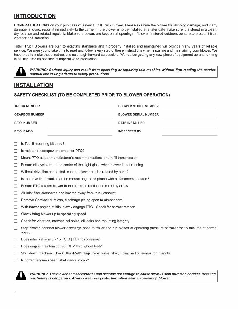
INTRODUCTIONCONGRATULATIONS on your purchase of a new Tuthill Truck Blower. Please examine the blower for shipping damage, and if any damage is found, report it immediately to the carrier. If the blower is to be installed at a later date make sure it is stored in a clean, dry location and rotated regularly. Make sure covers are kept on all openings. If blower is stored outdoors be sure to protect it from weather and corrosion.
Tuthill Truck Blowers are built to exacting standards and if properly installed and maintained will provide many years of reliable service. We urge you to take time to read and follow every step of these instructions when installing and maintaining your blower. We have tried to make these instructions as straightforward as possible. We realize getting any new piece of equipment up and running in as little time as possible is imperative to production.
WARNING: Serious injury can result from operating or repairing this machine without first reading the service manual and taking adequate safety precautions.
INSTALLATIONSAFETY CHECKLIST (TO BE COMPLETED PRIOR TO BLOWER OPERATION)
TRUCK NUMBER
GEARBOX NUMBER
P.T.O. NUMBER
P.T.O. RATIO
BLOWER MODEL NUMBER
BLOWER SERIAL NUMBER
DATE INSTALLED
INSPECTED BY
F Is Tuthill mounting kit used?
F Is ratio and horsepower correct for PTO?
F Mount PTO as per manufacturer’s recommendations and refill transmission.
F Ensure oil levels are at the center of the sight glass when blower is not running.
F Without drive line connected, can the blower can be rotated by hand?
F Is the drive line installed at the correct angle and phase with all fasteners secured?
F Ensure PTO rotates blower in the correct direction indicated by arrow.
F Air inlet filter connected and located away from truck exhaust.
F Remove Camlock dust cap, discharge piping open to atmosphere.
F With tractor engine at idle, slowly engage PTO. Check for correct rotation.
F Slowly bring blower up to operating speed.
F Check for vibration, mechanical noise, oil leaks and mounting integrity.
F Stop blower, connect blower discharge hose to trailer and run blower at operating pressure of trailer for 15 minutes at normal speed.
F Does relief valve allow 15 PSIG (1 Bar g) pressure?
F Does engine maintain correct RPM throughout test?
F Shut down machine. Check Shur-Melt® plugs, relief valve, filter, piping and oil sumps for integrity.
F Is correct engine speed label visible in cab?
WARNING: The blower and accessories will become hot enough to cause serious skin burns on contact. Rotating machinery is dangerous. Always wear ear protection when near an operating blower.

5
SPECIFICATIONS TABLE
MODEL
AIR FLOW RANGECFMm³/h
MAXIMUM PRESSUREPSIGBar g
MAXIMUM VACUUMIn. Hgmbar RPM RANGE
T850 225 - 565527 - 1700
201.37
17575 1000 - 3000
T1050 450 - 1200764 - 2039
181.24
17575 1450 - 3000
NOTE: Reduce the maximum operating pressure by 1 PSI (0.068 bar) for each 2000 feet (610 m) of elevation above sea level. Example: At an altitude of 4000 feet (1219 m), the maximum working pressure of the blower will decrease by 2 PSI (0.137 bar).
OUTLINE DRAWINGS
Dimensions shown are not on a controlled document and as such are subject to change. Certified drawings are available through your local Tuthill Truck Blower Distributor. Dimensions are shown in inches and millimeters.
68133
68
75
58
149
45676
576 317 298
640 349 308
OIL FILLLOCATIONHORIZONTALAIR FLOW
OIL LEVELGAUGEVERTICAL AIR FLOW
OIL FILLLOCATION VERTICALAIR FLOW
OIL DRAINHORIZONTALAIR FLOW
AB
C
8 × 1/2-13 UNC
2.685.25
2.68
2.94
2.28
3/8" KEY
Ø 1.625"
8 × 5/8-11 UNC
A B C
5.86
17.973
22.69 12.48 11.72
25.19 13.73 12.13
T850
MODEL
T1050

6
PTO SELECTION FOR TRANSMISSION
• Blower speed and pressure require adequate horsepower and torque. See performance curves on page 8.• Engine speed and blower speed require the adequate ratio PTO be installed for proper operation of the blower.• 6 and 8 bolt transmissions will provide the proper space for blower installation.
ENGINE SPEED
• Engine speed must be constant when blower is in the operating cycle. A constant speed governor or throttle control system must be installed to assure the proper blower operation.
PRESSURE RELIEF VALVE
• Relief valve must be sized for the correct air flow and pressure rating. Install valve as close to the blower as possible and before the check valve.
• Ensure that pipe compound is used on the threads of the male end of the relief valve to seal against air leakage.
CAUTION: An undersized or improperly set relief valve will cause the blower to operate at higher temperatures. This can cause the blower to overheat, causing irreparable damage.
AIR FILTER
• The filter should be selected to suit the air flow requirement of the application. Air filters should be used on food and plastic products to prevent contamination.
CAUTION: An undersized air filter will cause the blower to operate at higher temperatures. This can cause blower to overheat, causing irreparable damage.
SUCTION & DISCHARGE PIPING
• All piping should be free and clear of any welding slag or foreign material.• The suction piping requirement is a minimum of 5’’ (127 mm) diameter for proper flow to the blower.• Discharge piping minimum of 4’’ (102 mm) diameter.
CAUTION: Do not use a rubber elbow in the suction line during vacuum operation. The elbow will fail causing the blower to overheat. This will cause damage to the blower.
MOUNTING BRACKET
• Proper mounting of the blower with the correct bracket will reduce stress on the blower housing.
CHECK VALVE
• Minimum restriction for application, mount downstream of the relief valve. Size valve for maximum air flow (CFM or m³/hr).
MUFFLERS & DISCHARGE FILTRATION
• Minimum restriction for application, mount downstream of relief valve.
VACUUM VALVE
• Size for proper air flow and vacuum rating.• This valve should be located before the blower inlet filter. Normally this valve is mounted on the trailer.
NOTE: To properly protect the blower from overheating when vacuum loading, a vacuum valve must be installed.
7
PTO DRIVE SHAFT
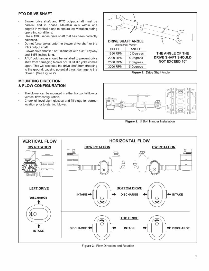
• Blower drive shaft and PTO output shaft must be parallel and in phase. Maintain axis within one degree in vertical plane to ensure low vibration during operating conditions.
• Use a 1300 series drive shaft that has been correctly balanced.
• Do not force yokes onto the blower drive shaft or the PTO output shaft.
• Blower drive shaft is 1 5/8” diameter with a 3/8” keyway and 1-5/8 inches long.
• A “U” bolt hanger should be installed to prevent drive shaft from damaging blower or PTO if slip yoke comes apart. This will also stop the drive shaft from dropping to the ground, causing potential thrust damage to the blower. (See Figure 2)
MOUNTING DIRECTION& FLOW CONFIGURATION
• The blower can be mounted in either horizontal flow or vertical flow configuration.
• Check oil level sight glasses and fill plugs for correct location prior to starting blower.
DRIVE SHAFT ANGLE(Horizontal Plane)
SPEED ANGLE1650 RPM 10 Degrees2000 RPM 8 Degrees2500 RPM 7 Degrees3000 RPM 5 Degrees
THE ANGLE OF THEDRIVE SHAFT SHOULD
NOT EXCEED 10°
Figure 1. Drive Shaft Angle
Figure 2. U Bolt Hanger Installation
DISCHARGE
LEFT DRIVE
INTAKE
DISCHARGEINTAKE
DISCHARGE DISCHARGE
INTAKE
BOTTOM DRIVE
CW ROTATION CW ROTATIONCCW ROTATIONVERTICAL FLOW HORIZONTAL FLOW
INTAKE
TOP DRIVE
Figure 3. Flow Direction and Rotation

8
25812151820PSIG
26101417In. Hg
0.250.751.001.251.38 bar
200300400500 mbar
200300400500 mbar
0.250.751.001.251.38 bar
bar1.381.25
1.00
0.75
0.25
mbar500400
300200
mbar500
400300200
bar1.381.25
1.00
0.75
0.25
In. Hg17141062
In. Hg17161210852
25812151518PSIG
25810121617In. Hg
PSIG20181512852
PSIG18151210852
1000 1500 2000
RPM
AIR
FLO
W A
T IN
LET
(CFM
)
2500 3000
1000 1500 2000RPM
2500 3000
1000 1500 2000
RPM2500 3000 3500
1000 1500 2000
RPM2500 3000 3500 1000 1500 2000
RPM2500 3000 3500
1000 1500 2000
RPM2500 3000 3500
1000 1500 2000
RPM2500 3000
1000 1500 2000
RPM2500 3000
025
200300400
500600
700800900
1000A
IRFL
OW
AT
INLE
T (C
FM)
AIR
FLO
W A
T IN
LET
(m³/h
)
AIR
FLO
W A
T IN
LET
(CFM
)200
0
AIR
FLO
W A
T IN
LET
(m³/h
)
AIR
FLO
W A
T IN
LET
(m³/h
)
0
250
750
500
1000
12501500
1750
0250500750
100012501500175020002250
250500750
1000125015001750
AIR
FLO
W A
T IN
LET
(m³/h
)
0250500750
100012501500175020002250
300
400
500
600
700
800
900
1000
AIR
FLO
W A
T IN
LET
(CFM
)
0150300450600750900
105012001350
0150300450600750900
105012001350
5075100BHP
0
25
50
75
100BHP
010
203040
5060
7080KW
05
10
15
20
25KW
051015202530KW
010203040506070KW
0102030405060BHP
0153045607590105120BHP
AIRFLOW BASED UPON INLET CONDITIONS OF: 14.7 PSIA & 70° F# PSIG DISCHARGE PRESSURE
AIRFLOW BASED UPONINLET: 70° FDISCHARGE: 29.92” Hg Abs
AIRFLOW BASED UPONINLET: 70° FDISCHARGE: 29.92” Hg Abs
AIRFLOW BASED UPON INLETCONDITIONS OF: 1 bar & 20° CDENSITY: 1.2 kg/m³BAR DISCHARGE PRESSURE
AIRFLOW BASED UPONINLET: 20° C DISCHARGE: 1 barDENSITY @ 20° C & 1 bar 1.2 kg/m³MBAR INLET VACUUM
AIRFLOW BASED UPONINLET: 20° C DISCHARGE: 1 barDENSITY @ 20° C & 1 bar 1.2 kg/m³MBAR INLET VACUUM
AIRFLOW BASED UPON INLETCONDITIONS OF: 1 bar & 20° CDENSITY: 1.2 kg/m³MBAR DISCHARGE PRESSURE
PERFORMANCE CURVES (US)
PERFORMANCE CURVES (METRIC)
T850 PRESSURE CURVE T1050 PRESSURE CURVE
T850 VACUUM CURVE T1050 VACUUM CURVE
T850 PRESSURE CURVE T1050 PRESSURE CURVE
T850 VACUUM CURVE T1050 VACUUM CURVE
AIRFLOW BASED UPON INLET CONDITIONS OF: 14.7 PSIA & 70° F# PSIG DISCHARGE PRESSURE
9
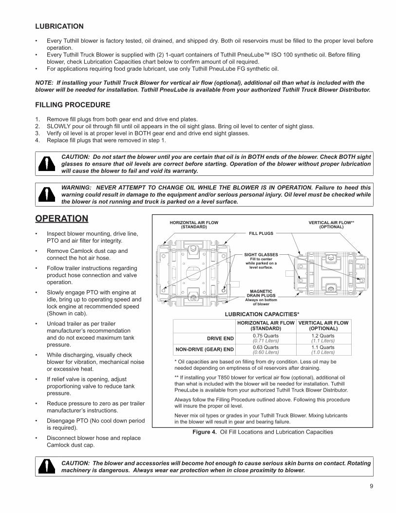
FILL PLUGS
SIGHT GLASSESFill to center
while parked on alevel surface.
MAGNETICDRAIN PLUGS
Always on bottomof blower
HORIZONTAL AIR FLOW(STANDARD)
VERTICAL AIR FLOW**(OPTIONAL) HORIZONTAL AIR FLOW
(STANDARD)
DRIVE END 0.75 Quarts(0.71 Liters)
1.2 Quarts(1.1 Liters)
0.63 Quarts(0.60 Liters)
1.1 Quarts(1.0 Liters)NON-DRIVE (GEAR) END
LUBRICATION CAPACITIES*VERTICAL AIR FLOW
(OPTIONAL)
* Oil capacities are based on filling from dry condition. Less oil may be needed depending on emptiness of oil reservoirs after draining.
** If installing your T850 blower for vertical air flow (optional), additional oil than what is included with the blower will be needed for installation. Tuthill PneuLube is available from your authorized Tuthill Truck Blower Distributor.
Always follow the Filling Procedure outlined above. Following this procedure will insure the proper oil level.
Never mix oil types or grades in your Tuthill Truck Blower. Mixing lubricants in the blower will result in gear and bearing failure.
Figure 4. Oil Fill Locations and Lubrication Capacities
LUBRICATION
• Every Tuthill blower is factory tested, oil drained, and shipped dry. Both oil reservoirs must be filled to the proper level before operation.
• Every Tuthill Truck Blower is supplied with (2) 1-quart containers of Tuthill PneuLube™ ISO 100 synthetic oil. Before filling blower, check Lubrication Capacities chart below to confirm amount of oil required.
• For applications requiring food grade lubricant, use only Tuthill PneuLube FG synthetic oil.
NOTE: If installing your Tuthill Truck Blower for vertical air flow (optional), additional oil than what is included with the blower will be needed for installation. Tuthill PneuLube is available from your authorized Tuthill Truck Blower Distributor.
FILLING PROCEDURE
1. Remove fill plugs from both gear end and drive end plates.2. SLOWLY pour oil through fill until oil appears in the oil sight glass. Bring oil level to center of sight glass.3. Verify oil level is at proper level in BOTH gear end and drive end sight glasses. 4. Replace fill plugs that were removed in step 1.
CAUTION: Do not start the blower until you are certain that oil is in BOTH ends of the blower. Check BOTH sight glasses to ensure that oil levels are correct before starting. Operation of the blower without proper lubrication will cause the blower to fail and void its warranty.
WARNING: NEVER ATTEMPT TO CHANGE OIL WHILE THE BLOWER IS IN OPERATION. Failure to heed this warning could result in damage to the equipment and/or serious personal injury. Oil level must be checked while the blower is not running and truck is parked on a level surface.
OPERATION• Inspect blower mounting, drive line,
PTO and air filter for integrity.
• Remove Camlock dust cap and connect the hot air hose.
• Follow trailer instructions regarding product hose connection and valve operation.
• Slowly engage PTO with engine at idle, bring up to operating speed and lock engine at recommended speed (Shown in cab).
• Unload trailer as per trailer manufacturer’s recommendation and do not exceed maximum tank pressure.
• While discharging, visually check blower for vibration, mechanical noise or excessive heat.
• If relief valve is opening, adjust proportioning valve to reduce tank pressure.
• Reduce pressure to zero as per trailer manufacturer’s instructions.
• Disengage PTO (No cool down period is required).
• Disconnect blower hose and replace Camlock dust cap.
CAUTION: The blower and accessories will become hot enough to cause serious skin burns on contact. Rotating machinery is dangerous. Always wear ear protection when in close proximity to blower.
FILL PLUGS
SIGHT GLASSESFill to center
while parked on alevel surface.
MAGNETICDRAIN PLUGS
Always on bottomof blower
HORIZONTAL AIR FLOW(STANDARD)
VERTICAL AIR FLOW**(OPTIONAL) HORIZONTAL AIR FLOW
(STANDARD)
DRIVE END 0.75 Quarts(0.71 Liters)
1.2 Quarts(1.1 Liters)
0.63 Quarts(0.60 Liters)
1.1 Quarts(1.0 Liters)NON-DRIVE (GEAR) END
LUBRICATION CAPACITIES*VERTICAL AIR FLOW
(OPTIONAL)
* Oil capacities are based on filling from dry condition. Less oil may be needed depending on emptiness of oil reservoirs after draining.
** If installing your T850 blower for vertical air flow (optional), additional oil than what is included with the blower will be needed for installation. Tuthill PneuLube is available from your authorized Tuthill Truck Blower Distributor.
Always follow the Filling Procedure outlined above. Following this procedure will insure the proper oil level.
Never mix oil types or grades in your Tuthill Truck Blower. Mixing lubricants in the blower will result in gear and bearing failure.

10
PREVENTATIVE MAINTENANCEA good maintenance program will keep your blower in top running condition. A newly installed blower should be checked frequently during the first month of operation, especially lubrication. Check oil level and add oil as needed. Complete oil changes are recommended every 500 operating hours, or more frequently depending on the type of oil, and oil operating temperatures. The following is recommended as a minimum maintenance program. An oil analysis program is recommended.
DAILY WEEKLY MONTHLY SEMI-ANNUALLY1. Check and maintain
oil level, and add oil as necessary.
2. Check air filter restriction indicator
1. Clean air filter. Clogged air filters can seriously affect the efficiency of the blower and cause overheating and oil usage.
2. Check relief valve to assure it is operating properly.
1. Inspect the entire system for leaks.
2. Inspect condition of oil and change if necessary.
1. Inspect the drive line bearings.
2. Change oil even if 500 operating hours has not been reached.
DISASSEMBLY AND REASSEMBLYDISASSEMBLY
1. Remove all oil drain plug and vent plug from both ends of the blower. Before removing any parts, match mark each component with a punch. This will allow the blower to be reassembled in the same position Match mark covers, endplates, housing, cover extension, and both rotors.
2. Remove drive key from drive shaft. Remove gear end cover (Item 7). Remove drive end cover (Item 6). This is best accomplished by using two small pry bars at the dowel pins. Tap on cover with a mallet while putting pressure on the cover with the pry bar. The cover will slowly move off the dowel pins. Inspect seal area on drive shaft for grooves and burrs. Remove drive shaft seal (Item 17) from drive end cover. Remove oil slinger assemblies (Item 13 & 14).
3. Remove bolts (Item 25) and washers (item 24) from rotor shafts on the gear end. Remove timing gear (Item 8) from the rotor shaft by using a gear puller in Figure 5. Rotate timing gear to the right and left, 3 teeth each direction from the timing marks on the face of the gears, as the gear is being removed. Inspect gear teeth for wear and pitting. Inspect rotor shaft keyway for wear and damage.
CAUTION: Blower rotors must rotate freely in order for timing gears to be removed correctly. If blower rotors do not move freely both timing gears must be pulled simultaneously. If gears are removed improperly, this will cause damage to the rotor keyways and possibly to the timing gears.
4. Remove bolts (Item 27) from extension covers (Item 5). Using pry bars and a mallet slowly remove the extension cover from the gear end and drive endplates (Item 4) as explained in step 2. Remove gasket (item 16) from endplates on both gear end and drive end.
5. Use jacking screws on endplate (Item 4), from the housing (Item 3). Rotors (Items 1 & 2) will be removed from the housing. When the gear end endplate is removed.
Figure 5. Gear Puller Illustration
1”2 5/8”
5 1/4”
2”
15/16”
1 7/8”
3/4” Drill Ø 11/16”Tap 3/4” - 16 UNF
7/16” × 1” Slot(Thru)
Snap-OnP/N CJ66-15-3or equivalent
Snap-On P/N CJ83-3or equivalent
Drive Gear Driven GearDrive Gear Driven Gear
Figure 6A. Timing Marks Matched Figure 6B. Timing Marks Advanced3 Teeth (Reference Marks Aligned)

11
Take a gear puller and attach to the gear endplate with the center of the puller in the center of the rotor shaft. Apply pressure pushing the rotor away from the endplate. Repeat this operation until both rotors have been removed. Remove the inner sleeve of the seal housing from the rotor shafts with a puller. Inspect and clean seal area on the rotor shaft.
6. Remove bearings (Items 9 & 10), seal housing (Item 12), slingers (Item 15), bearing shield (Item 11), and bearing shims (Item 31) from endplate. Use a hammer and bar to drive bearing and seal housing from endplates. Inspect bearing wear pattern and seal, for wear and heat marks. Clean all parts before inspecting. Check rotors bearing and seal fits for bearing spinning along with seal housing on rotor shaft. Check bearing bores and seal bores in endplate for spinning of bearings and seal housings.
ASSEMBLY
The components in the table on the right are available as a kit from Tuthill Vacuum & Blower Systems. These are the components that are replaced during a normal blower overhaul. As a minimum, these parts should be on hand prior to assembly.
GEAR END ASSEMBLY
1. Check all parts to insure the parts are clean and free of burrs or nicks that may have occurred when the blower was being disassembled. Check repair kit for the correct parts needed to complete the assembly of the unit. Make sure you have the proper tooling and training required to assemble the blower. Take the proper time to read the instruction manual before you begin.
2. Seat rotors (Items 1 & 2) on a fixture with the gear end of the rotors upward and in the “T” position as shown in Figure 7. Place a set of .006” shims on each rotor. Make sure the drive rotor (Item 1) is in the correct location for the proper flow and rotation required for the application.
NOTE: Use Loctite thread sealant on all bolts and cap screws that are assembled without lock-washers.
3. Install endplate onto rotor, make sure the shims on the rotor are still in place. Using a seal pressing tool (see drawing on page 15 for detail), press seal assembly (Item 31) onto rotor shafts. Press oil shield (item 15) onto rotor shafts.
NOTE: Oil shield is part of the seal assembly but must be pressed on after seal assembly is installed. On lip seal units, the seal must be pressed into the seal housing after the endplates have been installed onto the housing and before the slinger is installed on the rotor shaft.
4. Lay a straightedge across the top of the rotor shafts (see Figure 8). Put depth micrometer on the straightedge and measure the distance to the bearing shoulder on the endplate and the distance to the inner seal housing shoulder. Calculate the difference, this will be the amount of bearing shim (Item 12) needed for the proper clearance on the gear end. Install bearing shims and press in gear end bearings (Item 9) until bearing bottoms against bearing shims. Remove assembly from fixture and remove .006” of shim from between the end plate and the rotors.
Install housing (Item 3) to gear end endplate (Item 4) and tighten bolts to secure endplate to the housing. Install gasket (Item 16) onto end plate and install extension cover (Item 5) onto end plate and tighten securely. Check gear end clearance between the rotors and end plate.
NOTE: Install bearing retaining washer at this time if the blower requires retainers. Then check the gear end clearance of the unit.
Install gear key (Item 23) into keyway of each rotor. Make sure the keyways are in the correct position for the timing gears as shown in Figure 6A. Press timing gear assembly (Item 8) onto rotor with timing marks aligned on gear as shown in Figure 6B. Install rotor shaft washer (Item 24) and tighten. Check gear end clearance and record.
NOTE: If gear end clearances change, bearing shims may need to added or removed to maintain proper clearances.
MODEL T850/T1050 OVERHAUL KIT
ITEM # DESCRIPTION QTY
9 BEARING 2 EA.
10 BEARING 2 EA.
11 BEARING SHIELD 2 EA.
12 SEAL ASSEMBLY 4 EA.
16 GASKET 2 EA.
17 DRIVE SHAFT SEAL 1 EA.
18 O-RING 2 EA.
— PORT GASKET 2 EA.
— TIMING ADJUSTMENT SHIM 1 EA.
31 BEARING SHIM 8 EA.
DRIVE DRIVENFigure 7. Correct Positioning of
Rotor Keyways for Assembly
Figure 8. Using Depth Micrometerto Determine End Clearance
12
DRIVE END ASSEMBLY
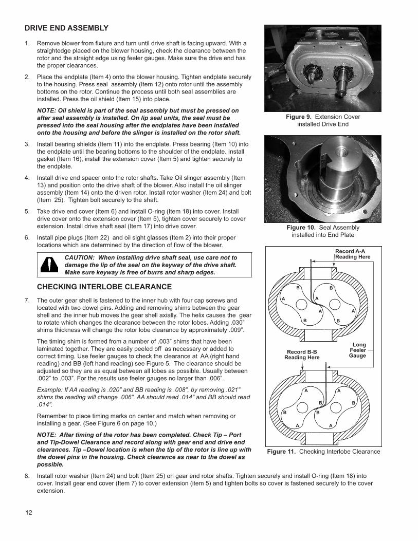
1. Remove blower from fixture and turn until drive shaft is facing upward. With a straightedge placed on the blower housing, check the clearance between the rotor and the straight edge using feeler gauges. Make sure the drive end has the proper clearances.
2. Place the endplate (Item 4) onto the blower housing. Tighten endplate securely to the housing. Press seal assembly (Item 12) onto rotor until the assembly bottoms on the rotor. Continue the process until both seal assemblies are installed. Press the oil shield (Item 15) into place.
NOTE: Oil shield is part of the seal assembly but must be pressed on after seal assembly is installed. On lip seal units, the seal must be pressed into the seal housing after the endplates have been installed onto the housing and before the slinger is installed on the rotor shaft.
3. Install bearing shields (Item 11) into the endplate. Press bearing (Item 10) into the endplate until the bearing bottoms to the shoulder of the endplate. Install gasket (Item 16), install the extension cover (Item 5) and tighten securely to the endplate.
4. Install drive end spacer onto the rotor shafts. Take Oil slinger assembly (Item 13) and position onto the drive shaft of the blower. Also install the oil slinger assembly (Item 14) onto the driven rotor. Install rotor washer (Item 24) and bolt (Item 25). Tighten bolt securely to the shaft.
5. Take drive end cover (Item 6) and install O-ring (Item 18) into cover. Install drive cover onto the extension cover (Item 5), tighten cover securely to cover extension. Install drive shaft seal (Item 17) into drive cover.
6. Install pipe plugs (Item 22) and oil sight glasses (Item 2) into their proper locations which are determined by the direction of flow of the blower.
CAUTION: When installing drive shaft seal, use care not to damage the lip of the seal on the keyway of the drive shaft. Make sure keyway is free of burrs and sharp edges.
CHECKING INTERLOBE CLEARANCE
7. The outer gear shell is fastened to the inner hub with four cap screws and located with two dowel pins. Adding and removing shims between the gear shell and the inner hub moves the gear shell axially. The helix causes the gear to rotate which changes the clearance between the rotor lobes. Adding .030” shims thickness will change the rotor lobe clearance by approximately .009”.
The timing shim is formed from a number of .003” shims that have been laminated together. They are easily peeled off as necessary or added to correct timing. Use feeler gauges to check the clearance at AA (right hand reading) and BB (left hand reading) see Figure 5. The clearance should be adjusted so they are as equal between all lobes as possible. Usually between .002” to .003”. For the results use feeler gauges no larger than .006”.
Example: If AA reading is .020” and BB reading is .008”, by removing .021” shims the reading will change .006”. AA should read .014” and BB should read .014”.
Remember to place timing marks on center and match when removing or installing a gear. (See Figure 6 on page 10.)
NOTE: After timing of the rotor has been completed. Check Tip – Port and Tip-Dowel Clearance and record along with gear end and drive end clearances. Tip –Dowel location is when the tip of the rotor is line up with the dowel pins in the housing. Check clearance as near to the dowel as possible.
8. Install rotor washer (Item 24) and bolt (Item 25) on gear end rotor shafts. Tighten securely and install O-ring (Item 18) into cover. Install gear end cover (Item 7) to cover extension (item 5) and tighten bolts so cover is fastened securely to the cover extension.
Figure 9. Extension Cover installed Drive End
Figure 10. Seal Assemblyinstalled into End Plate
LongFeelerGaugeRecord B-B
Reading Here
Record A-AReading Here
A
A
A
A
B
B
B
B
A
A
A
A
B B
B B
Figure 11. Checking Interlobe Clearance

13
9. Install pipe plugs (item 22) and sight glasses (Item 21) to the proper location. The direction of flow of the blower will determine their location.
ASSEMBLY CLEARANCES
Clearances are shown in inches and millimeters.
MODEL GEAR END DRIVE ENDSUM OF
GEAR END + DRIVE END INTERLOBE TIP-PORT TIP-DOWEL
T850 .004” - .009”.10 - .23
.013” - .018”.33 - .46
.021” - .022”.53 - .56
.013” - .017”.33 - .43
.006” - .010”.15 - .25
.003” - .007”.08 - .19
T1050 .004” - .009”.10 - .23
.015” - .020”.38 - .51
.023” - .024”.58 - .61
.013” - .017”.33 - .43
.006” - .010”.15 - .25
.003” - .007”.08 - .19
NOTES:

14
NOTES:

15
DRIVE SHAFT SEAL TOOL
SECTION A-A
SECTION A-A
SECTION A-A
SECTION A-A
SECTION A-A
SECTION A-A
CLEARANCE SETTING SPACER
END PLATE PRESS TOOL END PLATE SEAL PRESS TOOL
GEAR PRESS SPACER LONG SHAFT BEARING PRESS TOOL
PISTON CARRIER & SLINGER INSTALLATION TOOL ROTOR SHAFT LIP SEAL PRESSING TOOL
HYDRAULIC PRESS ROD
All dimensions are shown in inches and millimeters.
MATERIAL:TOOL STEELHEAT TREATEDTO 40-42 Rc
1/2-13UNC-2ABOTH ENDS
SEAL & BEARING INSTALLATION TOOL DRAWINGS
A
A
A
A
A
A
A
A
A
A
A
A
50.8
92.1
76.2
41.4
44.5
69.9
247.7
236.2
50.8 86.573.0
19.1 234.2
50.8
15.9257.2
73.0
1.5
4.0
88.8 72.4 69.9
5.1 88.958.4
44.5
9.5
268.0
257.2
12.7
48.1
3.2
38.1
44.5
5.6
104.8
5.6 50.5
60.3
157.5
7.6
48.560.1
± .02
± .013
50.8
3.3
76.5 49.6 60.0
30.5
12.7
1.0 × 45°
1.0 × 45°
1.0 × 45°
1.0 × 45°
1.0 × 45°
3.2 × 45°+0.025 -0.000
ø 89
ø 109.8
ø 63.5
ø 13.5
ø 6.6
ø 6.8
3.625
3.0000.300
1.628 1.908± .008
± .005
2.365
.040 × 45°
1.2000.128
1.954 2.3633.012
ø 3.502
ø 4.321 +0.001-0.000
1.7502.7502.8503.496
6.200
1.750
3.5000.2002.300
0.375
2.375
ø 0.258
.040 × 45°
.040 × 45°
.040 × 45°
.040 × 45°
.125 × 45°
ø 2.500
ø 0.531
2.750
0.220
1.500
1.750
0.220
4.1251.990 1.895
R 0.1250.500
10.550
10.125
2.000
9.300
9.750
2.000 2.8753.4052.875
0.156
0.750 9.219
10.125
R .06
ø 0.2660.625
2.000” 2.000”
0.500”

16
ROTOR SHAFT SEAL DETAIL (ITEM 12) STANDARD
PISTON/SLINGER SEALASSEMBLY
OPTIONALPISTON/LIP SEALASSEMBLY (-LS)
1
26
2
27
3 4
295 306
31
7
32
8
33
9
34
10
35
11
12
See Rotor ShaftSeal Detail(Item 12) Below37
13
3814 39
15
16
17
18
19
20
21
28
22
23
24
25
T850 / T1050 ASSEMBLY DRAWING
17
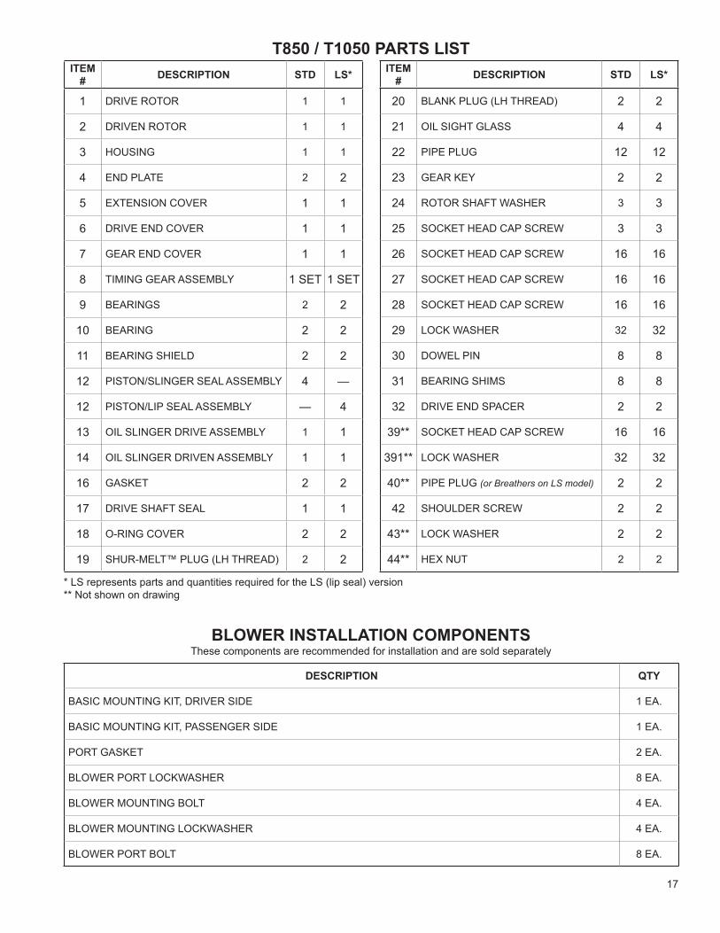
ITEM# DESCRIPTION STD LS*
1 DRIVE ROTOR 1 1
2 DRIVEN ROTOR 1 1
3 HOUSING 1 1
4 END PLATE 2 2
5 EXTENSION COVER 1 1
6 DRIVE END COVER 1 1
7 GEAR END COVER 1 1
8 TIMING GEAR ASSEMBLY 1 SET 1 SET
9 BEARINGS 2 2
10 BEARING 2 2
11 BEARING SHIELD 2 2
12 PISTON/SLINGER SEAL ASSEMBLY 4 —
12 PISTON/LIP SEAL ASSEMBLY — 4
13 OIL SLINGER DRIVE ASSEMBLY 1 1
14 OIL SLINGER DRIVEN ASSEMBLY 1 1
16 GASKET 2 2
17 DRIVE SHAFT SEAL 1 1
18 O-RING COVER 2 2
19 SHUR-MELT™ PLUG (LH THREAD) 2 2
T850 / T1050 PARTS LISTITEM
# DESCRIPTION STD LS*
20 BLANK PLUG (LH THREAD) 2 2
21 OIL SIGHT GLASS 4 4
22 PIPE PLUG 12 12
23 GEAR KEY 2 2
24 ROTOR SHAFT WASHER 3 3
25 SOCKET HEAD CAP SCREW 3 3
26 SOCKET HEAD CAP SCREW 16 16
27 SOCKET HEAD CAP SCREW 16 16
28 SOCKET HEAD CAP SCREW 16 16
29 LOCK WASHER 32 32
30 DOWEL PIN 8 8
31 BEARING SHIMS 8 8
32 DRIVE END SPACER 2 2
39** SOCKET HEAD CAP SCREW 16 16
391** LOCK WASHER 32 32
40** PIPE PLUG (or Breathers on LS model) 2 2
42 SHOULDER SCREW 2 2
43** LOCK WASHER 2 2
44** HEX NUT 2 2
* LS represents parts and quantities required for the LS (lip seal) version** Not shown on drawing
DESCRIPTION QTY
BASIC MOUNTING KIT, DRIVER SIDE 1 EA.
BASIC MOUNTING KIT, PASSENGER SIDE 1 EA.
PORT GASKET 2 EA.
BLOWER PORT LOCKWASHER 8 EA.
BLOWER MOUNTING BOLT 4 EA.
BLOWER MOUNTING LOCKWASHER 4 EA.
BLOWER PORT BOLT 8 EA.
BLOWER INSTALLATION COMPONENTSThese components are recommended for installation and are sold separately
18
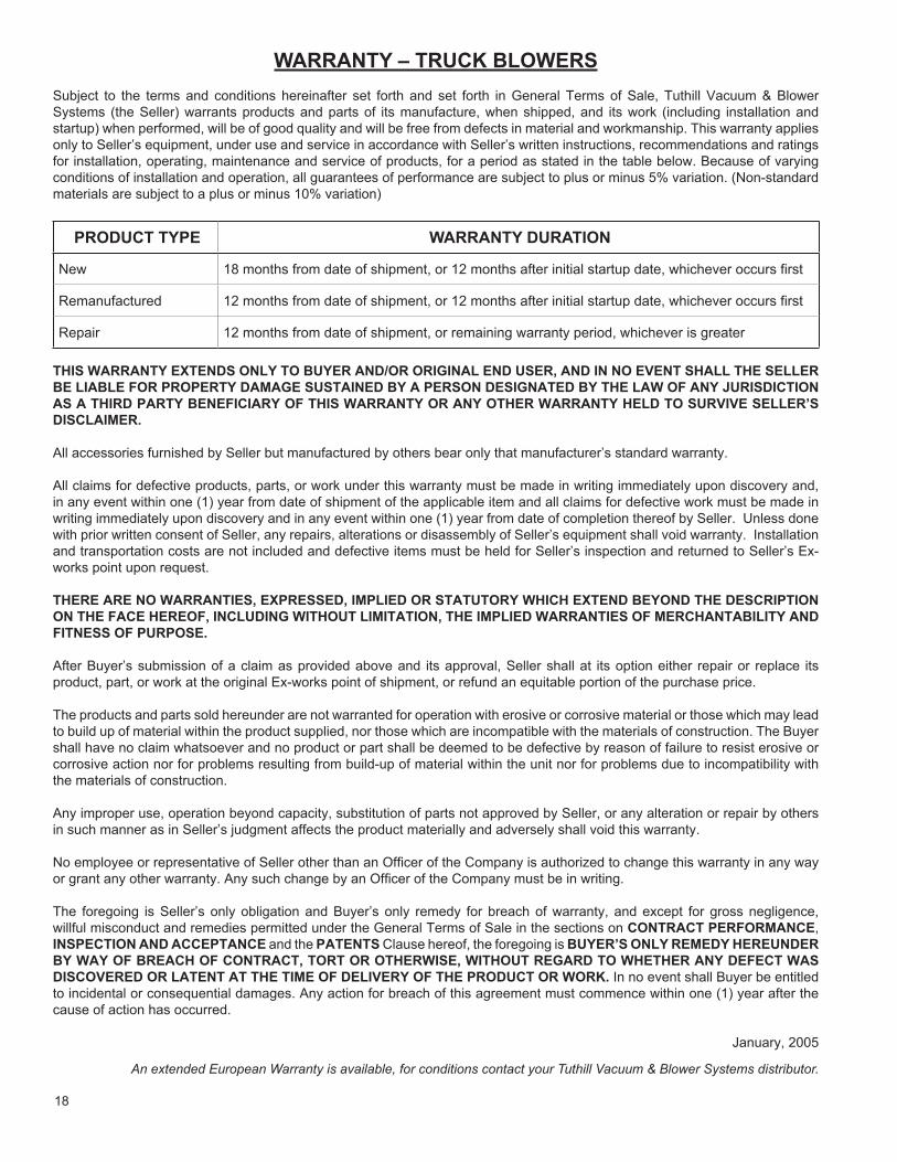
WARRANTY – TRUCK BLOWERSSubject to the terms and conditions hereinafter set forth and set forth in General Terms of Sale, Tuthill Vacuum & Blower Systems (the Seller) warrants products and parts of its manufacture, when shipped, and its work (including installation and startup) when performed, will be of good quality and will be free from defects in material and workmanship. This warranty applies only to Seller’s equipment, under use and service in accordance with Seller’s written instructions, recommendations and ratings for installation, operating, maintenance and service of products, for a period as stated in the table below. Because of varying conditions of installation and operation, all guarantees of performance are subject to plus or minus 5% variation. (Non-standard materials are subject to a plus or minus 10% variation)
PRODUCT TYPE WARRANTY DURATION
New 18 months from date of shipment, or 12 months after initial startup date, whichever occurs first
Remanufactured 12 months from date of shipment, or 12 months after initial startup date, whichever occurs first
Repair 12 months from date of shipment, or remaining warranty period, whichever is greater
THIS WARRANTY EXTENDS ONLY TO BUYER AND/OR ORIGINAL END USER, AND IN NO EVENT SHALL THE SELLER BE LIABLE FOR PROPERTY DAMAGE SUSTAINED BY A PERSON DESIGNATED BY THE LAW OF ANY JURISDICTION AS A THIRD PARTY BENEFICIARY OF THIS WARRANTY OR ANY OTHER WARRANTY HELD TO SURVIVE SELLER’S DISCLAIMER.
All accessories furnished by Seller but manufactured by others bear only that manufacturer’s standard warranty.
All claims for defective products, parts, or work under this warranty must be made in writing immediately upon discovery and, in any event within one (1) year from date of shipment of the applicable item and all claims for defective work must be made in writing immediately upon discovery and in any event within one (1) year from date of completion thereof by Seller. Unless done with prior written consent of Seller, any repairs, alterations or disassembly of Seller’s equipment shall void warranty. Installation and transportation costs are not included and defective items must be held for Seller’s inspection and returned to Seller’s Ex-works point upon request.
THERE ARE NO WARRANTIES, EXPRESSED, IMPLIED OR STATUTORY WHICH EXTEND BEYOND THE DESCRIPTION ON THE FACE HEREOF, INCLUDING WITHOUT LIMITATION, THE IMPLIED WARRANTIES OF MERCHANTABILITY AND FITNESS OF PURPOSE.
After Buyer’s submission of a claim as provided above and its approval, Seller shall at its option either repair or replace its product, part, or work at the original Ex-works point of shipment, or refund an equitable portion of the purchase price.
The products and parts sold hereunder are not warranted for operation with erosive or corrosive material or those which may lead to build up of material within the product supplied, nor those which are incompatible with the materials of construction. The Buyer shall have no claim whatsoever and no product or part shall be deemed to be defective by reason of failure to resist erosive or corrosive action nor for problems resulting from build-up of material within the unit nor for problems due to incompatibility with the materials of construction.
Any improper use, operation beyond capacity, substitution of parts not approved by Seller, or any alteration or repair by others in such manner as in Seller’s judgment affects the product materially and adversely shall void this warranty.
No employee or representative of Seller other than an Officer of the Company is authorized to change this warranty in any way or grant any other warranty. Any such change by an Officer of the Company must be in writing.
The foregoing is Seller’s only obligation and Buyer’s only remedy for breach of warranty, and except for gross negligence, willful misconduct and remedies permitted under the General Terms of Sale in the sections on CONTRACT PERFORMANCE, INSPECTION AND ACCEPTANCE and the PATENTS Clause hereof, the foregoing is BUYER’S ONLY REMEDY HEREUNDER BY WAY OF BREACH OF CONTRACT, TORT OR OTHERWISE, WITHOUT REGARD TO WHETHER ANY DEFECT WAS DISCOVERED OR LATENT AT THE TIME OF DELIVERY OF THE PRODUCT OR WORK. In no event shall Buyer be entitled to incidental or consequential damages. Any action for breach of this agreement must commence within one (1) year after the cause of action has occurred.
January, 2005
An extended European Warranty is available, for conditions contact your Tuthill Vacuum & Blower Systems distributor.
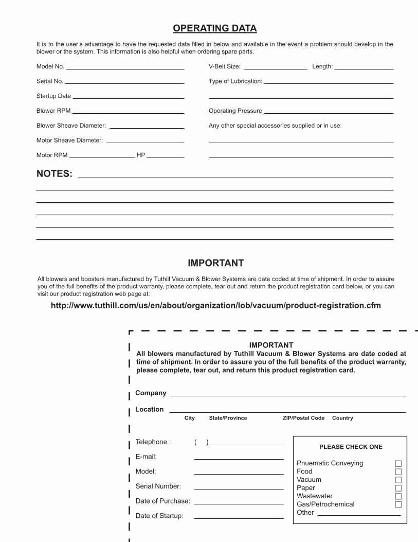
IMPORTANTAll blowers manufactured by Tuthill Vacuum & Blower Systems are date coded at time of shipment. In order to assure you of the full benefits of the product warranty, please complete, tear out, and return this product registration card.
Company
Location City State/Province ZIP/Postal Code Country
PLEASE CHECK ONE
Pnuematic Conveying F
Food F
Vacuum F
Paper F
Wastewater F
Gas/Petrochemical F
Other
Telephone : ( )
E-mail:
Model:
Serial Number:
Date of Purchase:
Date of Startup:
IMPORTANTAll blowers and boosters manufactured by Tuthill Vacuum & Blower Systems are date coded at time of shipment. In order to assure you of the full benefits of the product warranty, please complete, tear out and return the product registration card below, or you can visit our product registration web page at:
http://www.tuthill.com/us/en/about/organization/lob/vacuum/product-registration.cfm
OPERATING DATAIt is to the user’s advantage to have the requested data filled in below and available in the event a problem should develop in the blower or the system. This information is also helpful when ordering spare parts.
Model No. V-Belt Size: Length:
Serial No. Type of Lubrication:
Startup Date
Blower RPM Operating Pressure
Blower Sheave Diameter: Any other special accessories supplied or in use:
Motor Sheave Diameter:
Motor RPM HP
NOTES:

Tuthill Vacuum & Blower Systems4840 West Kearney StreetSpringfield, Missouri USA 65803-8702o 417.865.8715 800.825.6937 f 417.865.2950www.tuthill.com
NO POSTAGE NECESSARY
IF MAILEDIN THE
UNITED STATES
ATTN: CUSTOMER SERVICE – BLOWER PRODUCTSTUTHILL VACUUM & BLOWER SYSTEMSPO BOX 2877SPRINGFIELD MO 65890-2150
POSTAGE WILL BE PAID BY ADDRESSEE
BUSINESS REPLY MAILFIRST-CLASS MAIL PERMIT NO. 2912 SPRINGFIELD MO