Embed Size (px)
Citation preview

Subject : gas Dynamic and Turbine Machine ديناميك غازات ومكائن تور بينية : موضوع Weekly Hours : Theoretical:2 UNITS:5 5: الوحدات 2: نظري : الساعات األسبوعية Tutorial : 1 1: مناقشة Experimental : 1 1:عملي
week Contents األسبوع المحتويات
1. Principles of thermodynamics 1. اسس ديناميك الغازات 2. Introduction to compressible flow 2. مقدمة للجريان المنضغط 3. Isentropic flow 3. الجريان االيزوتروبي 4. Choked Isentropic flow 4. الخنق في الجريان االيزوتروبي 5. Operation of nozzles at variable pressure
ratios 5. عمل الفوهات عند نسب ضغط متغيرة
6. Normal shock wave 6. الصدمات االنضغاطية العمودية 7. Equations of Normal shock wave 7. العالقات المتحكمة بالصدمة العمودية 8. Oblique shock wave 8. الصدمة المائلة 9. Flow in constant area duct with friction 9. الجريان في بحاري ثابتة المقطع مع االحتكاك
10. Performance of long ducts at variable pressure ratios 10. اداء المجاري الطويلة عند نسب ضغط متغيرة
11. Isothermal flow in long ducts 11. ري الطويلةالجريان ثابت درجة الحرارية في المجا 12. Flow ducts with heating or cooling 12. الجريان في مجاري مع التسخين 13. = = .13 14. = = 14. 15. shock wave with change in stagnation
temperature 15 الموجات الصدمية عند تغيير درجة حرارة الرآود.
16. Aerothermodynamics of turbomachinery 16 الديناميك الحراري الهوائي للمحرآات التوربينية. 17. Physical principle
a. equation of motion b. continuity equation c. momentous equation
:المبادىء الفيزياوية معادلة الحرآة. أ معادلة استمرارية. ب معادلة الزخم. ج
17.
18 Turbine momentum notation
18 م التوربين معال
19. Efficiencies 19 الكفاءات 20 Flow in rotating blades 20 الجريان في الريش الدوارة 21. Axial flow turbine 21. تربين الجريان المحوري 22. Velocity triangles 22 مثلثات السرع. 23. Impulse turbine 23 التربين الدفعي. 24 Reaction turbine 24 التربين رد الفعلي. 25. = = 25. 26 Axial flow compressor 25 ضاغط الجريان المحوري. 27 Radial turbine 27 التربين الشعاعي. 28. Centrifugal compressor 28 الضاغط التنابذي.

Chapter OneFundamental of Ftuid Dynamics
Introduction:Gas dynamics is a branch of fluid mechanics which describe the flow of
compressible fluid. Fluids rvhich show appreciable variation in density as a resurts of theflow - such as gases- are called_ compressible fluids. The variation in density is duemainly to variation in pressure and temperature.The flow of a compressibre flu.id is govemed by the first raw of thermodynamics, whichrelates to energy balance, and by the second law of thermodynamics, which relates heatinteraction,and ineversibirity ro entropy. The flow is also a-ffected by both kinetic anJdynamic effects, which are described by Newton,s laws of motion. An inertial frame ofreference that is, a frame in *'hich NeMon's laws of motion are appricabre- is genera yused. In addition, the flow furfils the requirement ofconservation oimass.
These laws are not dependent on the properties of particular fluid, therefore inorder to relate the motion to a particurar fluid it-is necessary to use subsidiary laws inaddition to these fundamental principles , such as the equation ofstate for perfeci gas.
p - p R r . . . . . . . ( l )Ahhough the most obvious application of compressible fluid flow theory are in
the design ofhigh speed aircraft, and this remains an important application to the subject,acknowledges ofcompressible fluid flow theory is requirld in the disign and operatioi ofmany devices commonry encountered in engineering practice. Among these applicationare:
1- Gas Turbine: the flow in the balding and nozzle is compressible.2- Steam turbine. Here, too, the flow in the nozzles and biades must be treated as
compressible.3- Reciprocating engines, flow of gases through the valves and intake and
exhaust.4-
6-
Natural gas transmission line.Combustion chambersExplosive.
I.1 Co nserv ation of Mass :The principle ofconservation of mass, when referred ro a system offixed identity,
simple states that the mass of the system is constanl consiier an arbitrary contr6ivolume through which fluid streams Fig,l. we wish to derive the form of the law ofconservation ofmass as it applied to this control volume. However, in order to applythe law, we must begin with a system of fixed identity, and so we i"nn"a our ryitl"rias the fluid which some instant t occupies the control volume.
Next, we consider what happens during the succeeding time interval dt. Bydefinition, the control volume remains fixed in space, but the system moves in thegeneral direction ofthe stream.line. The two position of rhe system are shown in fig.1by dashed lines. For convenience in analyiis, we considei three region of spicedeooted bt I,II,III in fig. r. At time r the system occupies spaces 1 and IiI, and atitme/+d/ it occupies space l and .1L Thus, since the masi of rhe system is conserved, wewrite-

tn t r + nJr t = f r t na , I f r u , *a , . . . . . . . . . . . - . . . . . .2
where m11 means the mass of ttre fluid in space t at time t, and so on. A simplerearrangement then gives.
fr/ t+dt - frt t fru!, fru,*a
dtdtdtThe first term represent the time rate of change of mass within space .L But as d/ goes tozero space.Icoincide with the contrcl volume, and so in the limit.
f f i t , * a t - f r t t A .
dt '
at \" 'c u l
where mn denoted the instantaneous mass within the control volume.The third rerm may be wrinen.
* l * A*,"
ldt - /2q:I kdr =l.u,r'tt-,-a _ fa.^., ________-Sa t a t d t ) - '
where 6m1,*4l represent the amount of mass crossing the elementary surface dlo4 duringthe time dr. The ratio \mp*4/dt is called the out going flux of mass cross the area dAol,Or the mass rate of flow and is denoted for convenience by dmoul .similar reasoning yields for inlet.
m,, , ,.:, = ldn,. _______________6dI
and so the conservation law may now be expressed as
!o".t= !a^,.- [a,..,for detailed computation we note that ajt any instant
^,.= Ja.""= Loo,where dv is an element ofcontrol volume, p is the local mass density ofthat element andthe integral is to be taken over the entire control volume.d n " " 0 r r 0 o .
- = , I Pav = | :-4vd t d t 4v r , d l
with the help of fig.1 we may express the mass rate of flow in the form.
dmo, _Myt-a _ p(dA-)(V"dt) = pyd4",,
fur,*u,-------- 10
dt dtwhere p is the local instantaneous mass density in the neighbourh ood of dA.,r and y, isthe conesponding local instantaneous component of velocity normal to dAo",., with theforgoing expression equation 7 may now wriften.
Lp'= [cv.a't,.- !nv.a*a form which is usually called the equation ofcontinuitv.
When the flow is steady, ihe identity of the fluid within the control; volumechanges continuously, but the total mass remains constant or mathematical\ api6t is zerofor each element of contror vorume . Then equation r r state that the incoming andoutgoing mass rate of flow are identical.
t 1

jov"ae,, = lor/"ae". I 2For one dimensional steady state flow equationbecome.
P,v,A, = prvrA, l 3
fi5.(1) Flow through a contol volume(conrinuie equation)
of 9.2 One dimensional f ow
.fig..1.flov, through control yolume with obstacle( momentum equation)
12 for rhe inlet and outlet condition
T

Example: lTen kglsec of air enters a tank of r 0m3 in volume whire 2 kg/sec is discharge from thetank as show in fig. Ifthe temperature ofthe air inside the tank remains "onrtu-nt at 300Ko.Find the rate ofpressure rise inside rhe tank.Solution:Appling continuity equation
n A n
| :4r= lpv"dA'- lpy-d,r , 8 r
t A " l ' - r 6 . \
et
* = 287 *300**:68880 pysecOI lU
Example:2
A tank I ml in volume contains air at an initial pressure of6 atrrr (606.95 kpa) and aninitial temperature of25"c. Air is discharged isothermally Fom the tank at the rate of0.lm3ls. Assuming that the discharged air has the same density as tbat ofthe air in the tanlgfind aa expression for the time rate of change of density of the air in tl'e tank whatwould be tle rate of pressure drop i_n the tank a.fter 5 seconds?
solution:
Appling conrinuiry equation | 9k, = lpr/"A,. - lpV-d-A^ .t r ' o t
d p1 . 0 ; : - 0 . 1 0
or
d p
a r : - o ' t o
Separating variables and integrating gives:
/ " . \p : p , 2 _ 0 . 1 r : [
_ - t _ l e _ o . r ,
\ ^ 1 1 /
where subscript I refers to initial conditions in the tank pressure change may beexpressed in terms of density cha-nge according to the relation
P : P R T
dp dp
A : R r A : x z ( - 0 . l p )
but p= pRT 6p --6oSO -1 = .(1 --1
ot dI
so that:

-n 1 p, y -!)-- o-0 tr" ' " " R T , '
-0 .1p , s -o ' t '
Substituting numerical values gives:
#: - O.tX 606.95 X e-o.r(s) = -102.3 kpa/s
1.2- M o m e n t um co nse n ati o n t h eorem.The fundamental principle of dynamics is Newton's law of motion, and according
to this law the resultant offorce applied to a particle which may be at rest or in motion isequal to the rate of charge of momentum of the particle in the direction of the resultantforce. Newton's second law is vector relation. Consider the x-direction we write for thesystem.
Tr'=!!hY"l -----------t4d t '
Where the left hand side represent the algebraic sum ofthe X-force acting on the systemduring the time interval d/, and the right hand side represent the time of change of thetotal momentum of the system see fig.3.d , . , , , , , ( ^v , ) , , .0 ,+ (nv , )n , * , - (mv, ) , , - (mv, ) , r ,
*\mt/,)=ff i -----15
(mv,) ' ,., - (mV,), , --- as dl goes to zero this term represent the time rate ofdl
change of the X-momentum within the control volume. = 9f^r,1""otso that :
a .fr, =fit*v,t,.+ Jv.a^.,- !v,a.,.or
l o
fi, = fa'!t+ !or.v.at",, - !nv,v,a,, ---------t7

Example:3Air flowing isentropicarly in a nozzre strikes a stationary blade rvhen it leaves the
nozzle x shown in fig. Derermine :l- The magnitude of the reaction in the x-direction and in the y-direction needed to
hold the blade in place.2- The magnitude ofthe reaction in the x-direction and in the y-direction of the brade
moves towed the nozz.le at g0m/sec.Solut ion:
/ p , \ t r - t | t , / I \ 0 . / r . 4n : n l ; l : 3 0 8 { , r r / - 2 1 4 . 3 K
The eas v€locity at this scction is obtained from the enerEy equalion:
v2 t r2, , ' 1 , , / 2nt -f -l- - n2 + -t*
Therefore:r r 2 t r |
1 - = a P \ t t - t t ) - - i .
: IOOO(3O8 -rroa*$
from which V2: 266.46 m/s. The mass rate of flow is:
. i - p t A r r r - ( r r L \ n , n ,
/ 1 .5 x l .or3 x lo j \: | _______;\1_;;;_ l(25 x r0-.X60)
\ 2 8 . . . - - - , l: 0.258 kr,/s
Applying the nroalenturn equation to the control volume shown giees:
&- i(Vt, - Y2) : O.258(V3 cos 30 + ,'2): 0.258(266.a6 cos 30 + 266.46) : 128.28 N
and
\ - , i '(Vt, - V7): O.25a(n sin 30 - 0)- 0.258(266.46 sin 30) - 34.3? N
Y '-\\

(b) When ti.l1e blade 6oves toward the nozzle, the relative velocity is 26646+3A:296.46 m/s. The mass sttikinB the blade per ullit time now becomes:
/ 296.46 \i :0.258 | ... ^. l= 0.281 kE/s
From the velociry diagram shown:
V1,: 256.'14 rr.ls ar,d Vr: 148.23 m./s
The momeatum equatioo then gives:
&: i(Vz. - Vu\ -0281(256 t4 + 266'46) : 149'7 N
and
Rr : ;(v3r - vzlr: 0.287(148.23 - 0) : 42 54 N
Example:4
An airplane is traveling at a constant speed of200 m/s. Air enters ihejet engjne's inlet at
the rate of40 kg/s while tlle combustion products are discharged at an erit velocity of
600 m/s relative to the airplane. The intake area is 0.3 m2 and the exit area 0 6 nP' The
ambient pressure is 0.? atm, ald the pressure at the exit is 0.72 am,- calculate the net
:hrust developed by the engine. Assume uniform steady conditions at the inlet and exit
planes and the properties of the products of combustion to be lh€ same as those of
air.
Solution: consider the jet engine as a control volume as in fig. the air enters the enginewith a speed of 200m,/s. assuming horizontal flight and neglecting the momentum of thefuel, the net force opposite to thrust is:Appling momentum equation:
Rr : ;(v3r - vzlr: 0.287(148.23 - 0) : 42.54 N
since the case is steady state thus mean that 6pl&:0 therefore the momentum equationbecome
F: (pzAz + ;Vz , - (pLA . t + mVt )
: l ( O . ' 1 2 - O . ? ) l . o l 3 x l d x 0 . 6 + 4 0 x 6 0 0 1 - ( 0 + 4 0 x 2 0 o )
: 1 7 , 2 1 5 . 6 N
Vz- 2Oo nls V: - 600 m/s
- r d d v r , , , t ,I ,= L- ; ;* JV,dm., , - JV,dm,"
A: ' 0'6 mrP2 - O-72 attn

1.3The First La theEnergy is conveyed a cross the boundary of control volume in he form of heat and
(E r , *a, t E n,*a, ) - (E t , + E nt t )
work. Consider the flow through the control volume with of fig., with the systemdefined as the material occcuping the control volume at time t. we considei whathappens during the time interval dt. passing through the control surface are astationary strut and a rotating shaft attached to a turbo-machine, perhaps a compressoror turbine. The energy equation in a simple form can be written as following.Q _ d E + 5 Wdt dt dt
Rate of change of total energy E:
dt
dEdt
dtdt
B- work Done bv Shear stresses: This work may be conveniently divided into twocategories (i) the work done by the part of tle shaft inside the system on the partoutside the systemtowing to the torque in the rotating shaft resulting from the shearstresses. (ii) the shear work done at the boundaries ofthe system on adjacent fluidwhich is in motion. Therefore the rate change of rvork can be written as foilow.
# = r,* + W"0",, + ! n vd^.,, + [ n rd^,,
The total fluid energy per mass flow e is
dE _Et,*a,-Er,.* lrpr__ 116l_d t d t J d t J d t
6dE ,aE, | , t ,a= \ a ) -+ Jeamou,
- Jeamn
d E 1 d e p d v s , Ia,=L a
* )edm." ' - ledm.Rate of work done.
Omitting from our consideration capiliary, magnetic, and electrical force, thework done during the processes is the result of normal and shear stresses at themoving boundaries ofthe system.A- Work Done by Normal Stresses.
Taking the normal stress at the boundary of the system as the hydrostatic pressure.the work done by the system owing to normal force at an element of area dAoul ispdA""dx, where d: is the component of distance moved normal to dAo,,. BuI dAodxis the volume of the mass element dr27,17, *.hich volume may be writeen as v6m11,*4,-The total rate of work done by normal stresses during the process may now be setdown, with the aid of the foregoing, as
r\ t ._ Jpvbm,,,*o, _ Jpvdmtt,
= [rvd*",,- !nd,,,
Total fluid energ)': internal energy + kinetic energy + potential energy

yze = u + - + g z
u = h - p v = h - Pp
Substitute rhese equations into the energy equation results
Q = r r , . r * . * 1 o e d v , " r t 2 t t 2
d t . ea r , . . . sh@, , L d t
. ) {h+V+g4am. , , - f h+L+gz1dm, "
I .4Ihe r€qe4d Law of Thermodynamics:In a fixed-mass system entropy change occurJas a result of irreversibre events or as a
result of intemction with the environment in which there is heat transfer.t dQ - , as , | ,1,7=t;l- * J'd,,,* I'd,,"4 *, | 4!!+d spvd.t
.tr
for steady -one dimension flow. rln
rn (s , - s , )2 { }
for adiabatic flow dO=0 therefores, -s, )0 or ds>0 for isentropic flow ds=0 and flow adiabatic irreversible flow
ds>0
For most problem in gas dynamics, the assumption of perfect gas law is sufficientlyin accord with the properties ofreal gases as to be a acciptable. we shalr therefore setdown here the special thermodynamics relations which aiply to perfect gas.1- Eauation qf state:
pv = - = K l = -1 - - - - - - - - - - - - - -- o J {
Where.T is the absolute temperarure (K1, R is rhe gas constant(ykg.mol.Ko), S isthe univenal gas consrant and is equal to g134.3 J&g.mol.d" ,La ful i, tt "
molecular weight kgkg.mol. For atmospheric air berw,--.een 0 and i00 km,i\.{:28.966, therefore the air gas constant is 287.04 Jikg.K'
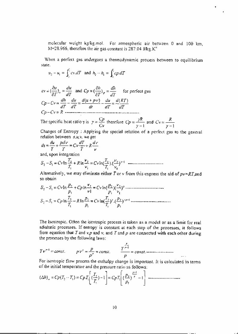
\!hen a perfect gas undergoes a thermodynamic process between to equilibriumstate.
r ' ' - " - h ,= f ' cn .d ru , - u t = t r . c v . d l a n a k - . f , .
,6u . du .Ah. dho = li), = dT
ana cP =\ *) e =
7 lor perlect gas
C p _ C u = 4 1 _ d u _ d ( u + p v ) _ d u - d T r )' d T d T d t d T d TC p - C v = R
The specif ic heat rat io y is 7= 94 11.r.1or. Cp=-fR - and Cu=
R,C v y - l 7 - 1
Changes of Entropy : Applying the special relation of a perfect gas to the generalrelation between tz,y we get
. du pdv ^ dT -dvd s = - + - = C v - + R -
T T T vand, upon integration
s, -.9, = cv ln A +.R Inh = cvtn( !21.1' r.,,uT , , , ' T r ' ' v r '
Altematively, we may eliminate either Zor v from this express the aid of pv=RT,andso obtain
S, -S, = 6'v1n P: + Cph!! = Crln(P' )(" ),P t V t A V t
S . - S , = C p l n 2 - R l n 4 = C v l n ( t z l r 1 P z ; t ' tt t Pr l r Pt
f - ' ' l | / - t IlLh) " = Cp(r. - r,) = Cp I,l (;) - t | = Cpr,l t "]1, - t I
L r r ) l h l
The Isentropic. Often the isentropic process is taken as a model or as a Iimit for realadiabatic processes. If entropy is constant at each step of the processes, it followsfrom equation tha* Tand v,p and v, and T and p are connected with each other duringthe prucesses by the following laws:
/+ , - t P T ' - )l v = C O n S I . p v = L = C O n S t - - = C O n S t .
p pFor isentropic flow process the enthalpy change is important. It is calculated in termsof the initial temperature and the pressure ratio as follows:
l 0

Chapter T*'oWave Propagation in Compressible f lorv
?.1 Lntroduction:The term compressible f lo$, impl ies var iat ion in densi ty through the f ie ld of f lou.
These r .ar iat lons are, in many cases, the resul t pr incipal l l , of pressure changes from
one point to anolher. The rate of change of densi t l ' \ \ ' i th respect to pressurg IS'
therefore. an importanr parameter in-the anal; 's is of compressible f lorv ' and, as ue
shal l see. i r is c iosely.connected ui th the veloci t l ,of propagat ion of snral l pressure
d is tu rbance . i . e . s i t h t he ve loc i t y o f sound .
2.2 \\ 'ale Propagation in Elastic \4edia:ler us er.mlne rr .hat happens *hen a sol id elast ic object such as steel bar is
subjeci ' �d ro a sudden unj form distr ibuled conrpressive stress appl!ed at one end. In
rhe f i rs i insranr of r inte. a thin Jal ,er ne.r t to the point of appl icat icn is compressecj .
uhi le the remainder of the bar is unaffected. This compression is ihen transmit ted to
rhe nesr la ler. and so on dor in the bar. Thus a disturbance created at the lef t s ide is
er,entual l r .sensel at the opposi te end. The contpression $aYe ini t ia led at the lef t s jde
of rhe bar rakes a f in i te t ime to t rarel to rhe r ight s ide. rhe rrare reloci i r beinS
depenienr on the elast ic iq ' ancl densi i l ' of the media'
Gas:s and l iquid also are elast ic substance and longi tudinal \ \ 'a\e can be
propagated through these media in the sa:re rral ' that \ \ 'aves propasated rhrough s-ol id '
L. , 'u g. , be cor l ined in a long tube u i th a piston at the lef t hand. The piston is gir er l
a sudcien push to t l re r ighr. In the f i rst instant a layer of gas pi les up nert to the pls1on
and is compressed. the remirder of the -sas is unaffected The compresslon rrare
creared b;, t i re pisron rhen mo'es through the gas unt i l eventual ly al l the gas is able to
s.ns. rh. *o, , . i r rent of rhe pisron. I f the impulse given to the gas is inf in i tesimal l ; '
smal l . the uare is cal ied a sound s 'ave and the resul tant compression \ \ave mo\e
rhrough the gas at veloci ty equal to the veloci ty of sound.
Let the pressure change across the u ave be dp and Jet the corresponding density and
,.rp.rrrur. change be dp and dT respectively. The gas into $hich the $'ave is
propagared is assrlmed to be at rest. The *'ave *,ill then induce a gas t'e)ocit; dl'.
tenirrJ it as it move rhrough the gas. The changes across the '.'are are, therefore as
sboru in fig.2.2. In order to analyze the florv through the uave and thus to deternline
(a). i i is co-nr.enient to use a coordinated s)slem that is anached lo the $ave. i .e, is
moving Nirh the $'aYe. In this coordinate s) 'stem, the rvave $' i l l ofcourse be at rest
and rhJgas * i1 l ef fecr i 'e ly, f lorv through i t * l ih the 'e loci t , , .a. ahead of the r 'ave and
a .'elocil'. a-til/, behind the rvare ln this coordinate system. lhen, the changes
through t ie \ \ar.e are shortn in f ig 2 3. The pressure. temperature and densi ty change'
ofcourse. independent of the coordinate systeln used
i---+-' D::t
, - a : =l llF-)--
lh',,"xtI'
l l

The cont inui t l ' and mqm-enfum equat ion are appl ied to a control volume of un;t area:cross rhe \\,a\:e as indicated ln fig. For steady state the conrinuity equarion for thecontrol volume is:nt' - Sn :(p + dp)(a - dV) ------------------2. 1r 'here m is ihe mass lo* ' rate per uni t area through the u,a'e. Since the case of a 'e11*eak is being consider. the second order term. dpdl l ihat ar ises in equat ion can beneg)ected and rhis equat ion rhen. eires:
nd p = ' ; 1 ' - " ' - - - - - - - - - - - - - - ' - - - - - - - l l
Q
Cons:n ai : ; . : of ; t ro; , . rentum is nert considei-ed. The onJl , for.ce acl i rg orr ihe co;t t roi'o iume ar: ihe pressure force. The mor)tentur) t eqrar ion for sreaciv state becorne:p . .1 * (p+d t1 .1 = , , , ' l@-d t , ) -o ] - - - - - - - - - - - - - - - - - - -2 . ju hlch leaci :o:
,4dp = n1'r11t o, dp = padl ' - - ------- 2.1Subs r i : u te equa i i on 2 .2 i n to equar ion 2 .4 s i ves :
;- G.T=o . o , , = . :+ __ - . - ___ t . 5a p \ d p
In orcer to e 'aluare a using rbe abore equai ion. i t is necessary 1o kno* ' rhe processlhat rhe sas undergoes in passing through the *,a 'e. Because a 'erv *eak *are isbeins considered. the ternperarure and'eloci ty chanees rhrough the *,a 'e are 'er 'smal l and t i :e sradient of iemperature and'e)oci t1,* i rhin the u,ave remain smal l . Forihis reason. heat t ransfer and' iscous effect for f lorv rhroush rhe u,ave are assunred tobe nee ) ig ib le . Hence . i s pass ing rh roueh rhe r ra re . rhe sa i i s assumed 10 underso anisentropic p;ocess. The f lot ' through rhe u'ar e is. therefore. assumed to sat isf_\ , :
tL = co tis!. --------------- - - --2.6p
puuine this inro iogar irhlnic form. and di f ferenr iat ing ihe equarion;) n p - ; r l n p = 6 6 p 5 1 .
lp do du .D..L = -', --L
p p d p pnot ins lhat ihe f lu jd is compressible and is perfect gas, therefore p=pRf subst i tur ingt h i s i r t o e " ' r : ' i n n r 7 : n d e n " : r j o n 1 . 5 .
/t,,o = * =. / ;1R r __--__________2.8
dp
t ' )

2.3 Pressure Field Created by a Moving Point Disrurbance:
In order to illustrare *le "ifeJt of the velJcity of rhe bodi' relarive to the speed of
sound on the f low R"tc, consio. , rhe smal l bodl ' , i e, essent ial ly a point sou.rce of
disturbance, to be movlns ar a uni forrn l iner veloci ty ' through the gas and. let the
;p: ; ;?"t i l " ; " ; ; " ; ; t be a Al though the bodv is essenrial lv emit ted *are
cont lnuously, a serres or * ,are emitred at i ime inten'al t $ i l l be consider. Since the
U"i t ' " "
- ; ; f "g rhrough t t t " gut ' the or i -eir of . these
*a'es * ' i l l be cont iniJal l - r '
.hrnoino \ \ rave senerated ar t i r ie 0 t '2t ' anJ i t u i l l be considered First ' consider ihe
:#i i ; :;. ;; 'pi. i " i ,r," u"iv is i 'ei1 smat) compared ro the speed of sound'.The
;;;; ' ; ; ; ; ;;" '- irhich exjsts utinf in' i"nt is then iound bl superposit ion of al l the
pressure pulses rr l l ich t t t ' " p"t iousl l ernj t ted' Fig shorrs sereral pressure pulse
n a t t e l n f o i d i f f e r e n t r ' a | u e o f r h e s p e e d o | t h e s o u r c e c o m p a r e d r r i t h t ] r e s p e e J o f- .oun d in rhe f l u id.
l ' )
Fie (2.3). Pressure f ie ld produced by a point source ofdis lurbance mor ing at
uniform sPeed leftu ards'(a) IncomPressible fluid (I//c : 0)'iui Subsodic moriot (V /c = rr57-icj Traosooic motion (7/c : l)f;i S;;eff";'i-"";ot]on', iti*ttt'tiog Karman's three rules of supersonic flow
(v /c : 2).
*- Incompressible Florv: \ \ ihen the mediurn is incompressib)e ( f ig 2 3a ) or rr hen the
speed ofrhe moving point ai ' i ' i lunt" is smal l compared rr i th the speed ofsound' rhe
pressure pulse spread uni forrnl i in al l d i rect ion'
I J

*- Subsonic Flo*: \ \ ihen the source mo'e at subsonic speeds. Fig.2.3b. rhe pressuredisturbance is t 'eJr in al l d i recr ion and ar al lpoints in spaie, but th i pressure parrem is no)on ger s l mmeir ical .*- Supersonic Floiv: For supersonic speed Fig.2.3d indicates lhal the phenomena areentirel-v different from those at subsonic speed. All the pressure djsturLance are includedin a cone *hich has rhe point source ofdisturbance. The cone r ' i th in r ' i r ich thedislurbances are conf ined is cal led the Mach cone. Fig.2.3c shoq,s the pressure Denem atthe boundar-r ' benr een subsonic and supersonic. that is- for the case rr lLere rhe si .eamr eJocir l is ideni ical rv i rh rhe sonjc ve)oci ty: here the u,ave front is a plane.
Karman's RuJes ofSupersonic Fro* : Fig 2.3 i i lusrrates the rhree rules ofsupersonici iorv proposed l r \ r2n Karr lan's .
1- The Rules ofForbidden- Signars. The effecl ofpressure chanse produced by arodr r t ror ins ar a speed faster rhan sound cannol reach point arread of rhe boir , .
2 . - Thezone o f Ac t i on and the Zone o fs i l ences . A s la r i ona ry po in r sou rce i n asupersoi ic srream produces ef lect oni 'on J:oint that l ie on or inside the \4achcone er:ending doNnsiream f lor:r the poir ' r t source. converselr ' . tbe pressure anc. lreloci t r ar a:r arbi t rarv point of the slream can be inf luenced o,.r lv b 'disrurbun.":cr ine ai point rhat l ies on or inside a cone ertending upsrrearn f ioni rhe poinrconsideied and havine the sante verrex angle as the \ ,Jach cone.
, t - The Ru le o fConcen t ra ted Ac t j on . The p ressu re d i s ru rbance j s l a ree l vconcenlrated in the neighbourhood ofrhe - \4ach cone that for:ns rhe-ourer l i ; r i r ofihe zone of act ion.
2. .1 Tbe \ lach Number and the i \ lach Angle:I i *as sho*n that the nature of the f lorv pal tern depends on rhe comparar i 'e
nrasnirudes ofrhe slreanr 'e locir1, and rhe sonic 'eloci t l , . The rat io of t i iese . ,or eloci t l , is cel led rhe \4ach , . -umber. Thus.
I.'
-2.9a
Tl ie semi-angle of rhe,\4ach cone is relared ro the i r4ach nunrber b,r ,
Noie that rhe mach ansle is
Example:
. is : : l d = - - - - - - - 2 - 1 0
.\.!imaginarv for subson ic fou,.
An obsener on the ground f inds that an airplane f fy ing bor izontal ly at an al t i tudeof 5000 m has traveled l2 km from rhe overhead position before the sound of rheairp)ane is first heard. Estimate rhe speed ar u,hich rhe airplane is flying.
1 t

SolutionI t is assumed rhat the net d is turbance proCuced by the a i rcraf t is weak, i .e . . that ,as ind icated b-v the wording of the quest ion. basica i ly * 'hat is being invest igated ishow far rhe a i icraf t * i l l have t raveled f rom the overhead posi t ion u 'hen the soundwaves emitted by the aircraft are first heard by the obsen'er. If the discussion oflvlach s'aves given above is considered, it tt ' i l l be seen lhat, as indicated in Fig.E3.9, rhe aircraft rvill first be heard by the obsen'er when the Mach \r'ave emanai-ins f rom the nose of the a i rcraf t reaches the obsener .
Now, sincc thc lamperulure \ 'ar ies throlgh the a',nospheie, lhe spccd ofsounC |arjes as the sou;rd \r 'ales p!ss lsun through lhe almcsphere rhichme!ns that tbe \{ach 'eres irom lhc aitcraf l arc aclua:l ! cur\:d. This ef; ' :ct is,ho\1c!ar, anal l and r\ i l l f 'a neglectcd here, th. sounC sPaed al th. avetala tem-p3ratrre bai\rc.n :hc gio,Jid and lhe sirciaf i bcitg used lo d: icrrbe the \ ' lach
No* as discuss3,j in Erimple i . l , for al l i tuC.s, H. cf f :on 0m (se"- ;91; -l . \ e l ) Lo l l 019 n I he i cm le ra iu t c i : l ! : a a lmosphc re : s g i r en b1 I =: ( ( l 6 - l ' 0 / A ( r / sL1 ! : l : . c Fe r : r i : l i : u i : c f l j i l : : . t h : t e : r pe : . : t - : : t s: 33 .16 - 00065 x l i l : { = l i l . 9 K . Hen .e , t he nca r spe3d o f sc r r , d i s g i r : n b1 :
o = jlnr = \, Tlll$ or " r,-rg = 330.6m;s ,_-
From rhe abore f igure i t * i i1 be seen iha t i f o i s the l r lach ang le based on lher.:]ean speeC of sound then
tan o = 50CO/ i2 000 = 0 .117
But s ince s i i ro = l / -V , i t fo i lo*s tha t "vns=1/v$ lz i 5s
HeDce. i t fol)o$ s lhat:
| c loc i ty o f a i rc ra f r = l 6 ' l jO 6 . 859 6m. 's
Problem:4 V
l . I Air at a temperalure of 25"C is f louing ni th a veloci ty of 180 mis. A project i leis f i red into the air stream rvi th a veloci ty of 800 m/s in the opposi te direct ion tothat of the air f fow. Calculate the angle that the Mach waves from the project i lemake to the direct ion of mot ion.
2.2 An obsen'er al sea level does not hear an aircraft that is fl;'ing al an altitude of?000 m until it is a distance of 13 km from the observer. Estimate the Machnumber at which the aircraft is ffying. In arriving at the answer, assume that theaverage temperature of the air betrveen sea level and 7000 m is - l0'C.
An obsener on the ground finds that an airplane fl)ing horizontally at an/ ' ) a l t i tude of2500m has traveled 6km from the overhead posi t ion before the
sound of the airplane is first heard. Assuming rhat, overall, the aircraft createsa small disrurbance, estimalc the speed at u'hich the airplane is fl;ing. Theavcrage air lemp€rature between the ground and the altitude at $hjch theairplane is ffying is I0"C. Explain thc assumptions you have made in arrivingat the answcr.
( l / ' 0 . { I i ) r -
l 5

In rhe absent of electromagnet ic force and t t j th f r ict ion neg)igib1e. the only force act ingon the control suriace are pressure force.,Assume that a pressurep-dp/2 acts on the sidesu r face ofrhe control rolume.
dp.p.-1 + ( p + z)d,4 - ( p + dp)(A + dA) = QA V )( + d t/ - V ),
a
Simpli f f ing I ields.dp=p l 'dv =0
The energl, equation s ith no extemal heat iransfer and no tr ork. for stady one-d imensional f lo l ' beconre.
, r )l(h + ;)( nt/d'a) = 0 ---------------
J_- ro r d h + d _ = 0
lAn expression lor the second las'of thermodl 'nanr ic is s iven :
.. Jp clpTds = dh - z :n,.i ,'or iseniiopic flou ds=0 .therefore dh = -:-
p p
Conrb in ing these equa t ion te ob la jn :
dt) I" r = - d - - c r d p - p l d l = 0 r r h i c h i s t h e s a n t e a s l l t e I r t o r t t e t r : u t n e q J 3 1 i ( r t .p J
3.3 Isentropic f lou'Tluou-eh a \/ar1 ing Area Charurel.Combining rhe cont inui i l 'and momenium equat ion for isentropic f lou'resul t in.
. . . t dp. d. t fuu -1- pt I
I p A JBut
Y = at fherefore. for isentrop:c f lorr 'ep
)^ / lJ I ldp - pl ' t ( -
"P. - l i t = 0 rnd - i l = -' p2: .1
' a
dp(t- -\1'�)= pp'= + --------------------3.3,1
Equat ion 3.3 demonstrates the inf luence of \4ach number on that f lorv. For V< i ,subsonjc flou,. rhe terrn ./--1./ is positive. Therefore, an increase in area result in anincrease in pressure and from equat ion 3.2 a decrease in veloci ty. Liker l ise. a decrease inarea resul ts in decrease in pressure and an increase in veioci ty. For supersonic f lou' , thererm I -1t42 in equat ion 3.3 is negat i le, and opposi te var iat ion occur. The:-esul t i l lustratein f ig har,e ramif icat ions. Subsonic f lo* 'cannot be accelerated to a veloci ty 'greater thant l re veloci ty ofsound in a converging nozzle. This is t rue i r respect ive of lhe pressuredifference imposed on rhe flon, through the nozzle. If it js desired to accelerate a strearrfronr negl ig ib)e veloci t l , to supersonic le loci t l ' . A convergenl-diversent channel nrust beused as shou, in fi e.
3.2
17
S T J B S O X T CD I F . F t , S E R
F l o ' 6 d c c r . o r . t : - : : - : +
*a i v t? . , , .k , r l ' ,> , ) ' j l i " ",44' z1'7 '
.t n- I///{" ,,rlrg}j,. /<r'
' .
'ffi-z'tz;:,1. ' iF . Jt--= .;):.4 j ' , .- l . l- -;
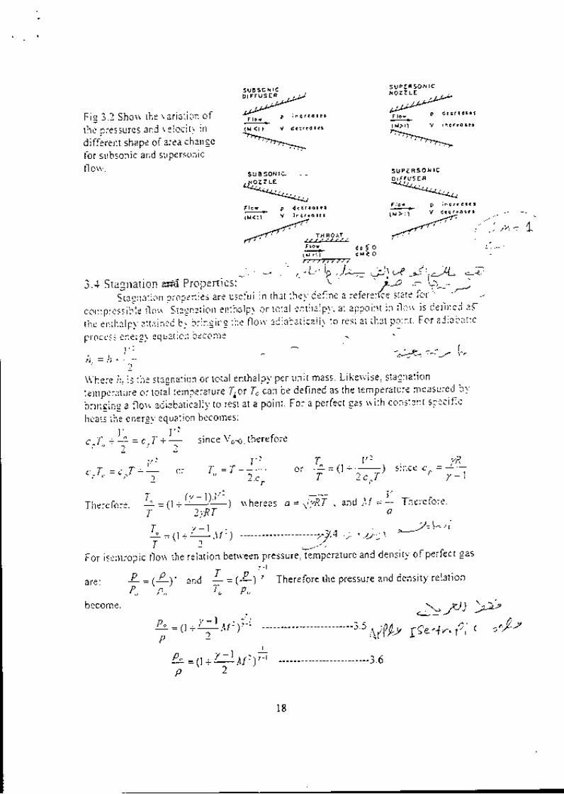
.1.-1 Staenation e*d Propenies' \ lJ - - \.- ,--.Stagnai ion propenies are useful in t l rat rhel 'def ine a referen'ce slaie i 'or t -
compressib- le i lorr . Siasnat ion enihalpl or total enthalpl ' . at appoint jn f lorr is def ined ai
rhe enihaJpl anained b) br inging rhe f lor i ' adiabat ical l l to rest ai that po:nt . For adiabat jc
Fig 3.2 Shorv rhe r .ar iat ion ofthe pressures and r eloci t f indifferent shape of area chaneefor subson ic and suPersonlcflorv.
process enerqJ eq u al jon b.con]e
' 1
are: P -P.
become.
S L J p E F S O H T Co r t F u s E R-144aQrJar&
F l o t - D i n c r . o t . r
-*la. +:,r- lr,-
, , , - - r=+ * ?=,, ' , " ! i s i ,c*." =JL
\ \ 'here f t , is the stagnat ion or toral enthalpy per uni t mass. Like* ' ise' stasnat ion
ternperature or total temperatu re Tpr To can be defined as the temperature measured bv
br ir ig ing a f lo*, adiabat i ia l ly to rei t at a point . For a perfect gas * i th constant speci f ic
heats the enerqv equat ion becomes:' t , | ; ?
c,T" + | = c ,T +; s ince Vo-4. therefore! !
- . . . ' : vTherefore. *=tr- '* i- I uhereas a -- � . lyRf ' and tr4 =- The: 'efore'
' T 2 t R I a
T v - l ^' r = ( l : - . \ 1 t ) - - - - - - - - - - - - - - - - - - - - r J . 4 , , , - \ L - - - ' / c : - ' l
: . \ ' 1 . /
For isenrropic 1 ' lo* ' rhe relat ion bet\ \ 'een pressure. iemperature and densi ty ofperfect gas
(2\ ' and ' = t ' l l Therefore the pressure and densi ty relat ion' p , , ' T " p "
l' = (1 t+M,)r -------- -------------3.s Alf!,
1 _ Lb =X +
| t ' t :)/-r -------------------- '----3.6
4-\,lJJ >
19e,1., (i' ( on,Lz
F r o r P I n I r : e r '
( x < l l v d . . r . o t c r( x < l l v 6 . . r 1""""rb_
s r rgsoN lc - - -
l 8
3.5 Florv per Unit Area.Ne\t \ \e ui l l der ive a useful relat ion betueen the
temperature. pressure and \4ach number lor perlect gas.con t i nu i t y , . r e make the fo l l o r r i ng a r ra r r ce rnen ls :
nt ' . . D . . p l ' t ' / iT, l- - - - . - r j - :
.1 RT .,7Rf \ ,t I I \j4Subst i tute equat ion 3.4 for adiabat ic f lorv
r ; " - " r_ : L = . : : , _ L . \ 1 . : ' t _ , ' . \ l - - _ _ _ _ _ _ _ _ _ _ _ _ _ _ 1 . ?
I | R l r I l' " ' a ' a
To f ind a c.rnr ent ional formula for the mass f los ' per uni l area in terr ls of \1. u ee l i n r i na te p i n t he equa t io r r abo re b1 'n reans o f the i sen t rop i c l an ' re l : t i on . o r su 'os t i t u teeq ua t i on 3 .5 .
D l t ' ! l )
r l r D" ' - \ ' "
j\l
florv per unit area. stag-nationStaning u, i rh rhe equarion of
---------------3.8r - l
, t / - t
l . / l \ : r ' - l )' )
i .6 \4axi ; rrunr Flot ' per Unit Area: To f ind the condit ion of marinrunr lorr peru r : i t a lea r r e cou ld d i f i e ren t i a te equa t i on -1 .S t r i t h res lec t t o \ { and se t t h i s de r i r a t i r eec .ua l i o ze lo . . l t t h i s cond i i i on . ue u ou ld l l nd tha t \ 1 -1 . The re fb re to f i nd t r r . i r , . " - \ \ eneed on l l se t \ 1= l i n equa t i on i . 8 . t hus r re f i nd .
, ' ' ' , - ' ' ' - Er j*r# t= -----------------3.9| . , . ) . . , = - . ; = r , _ ( - l , . , = -
. l . + \ K 7 + ) . , 1 o
For a given gas. therefore. the nraximu;:r f lo*,per u;r i t area depends only on therzt to p.AT". For a gir en value of the stagnat ion pressure and stagnat ion temperature andfor a passage r l i th minimum area. Equat ion 3.9 shou's tbat maximum f lo* 'uhich can bepassed is reJat ivel ,v )arge for gases ofhigh molecular weisht and relat iveJl 'srnal l for gasesof lou' molecular * 'e ight. Doubl ing the pressure level doubles the marinum f lou' .\ he reas dcub ) ing rhe abso lu te l en lpe ra tu re i e re l reduce the r ra r imum f l o$ b1 ,a bou t 29per cen t . Fo r a l r r r i t h ; ' =1 . - l and R=187 J kg .Ko rhe tna r imum mass f l o r r pe r un i t a rea i : :
= 0.0.10-12
The panicular value of the temperature. pressure and densi ty rat ios at the cr i t ical state( i .e at the rr in imu;n area) are found by sef i ing M=l in equat ions ] .4. 3.5. i .6, We u, i l lre i 'er ro the cr i t ical propert ies by superscr ipt aster isk (*) .T' ')- = ( - l l O r a l I = U . d J - )T" " / +1 '
t1 /L = 1 -
\ t - t l n r 2 i r = 0 i t S j- \ . )p . 7 + t
^ l
= ( ; ) ' - ' fo r a i r =0 .6339y + r
t e { (
3.7 The area Rat io .Just as \ \ 'e have found j r convenient to uork rr i th rhe dimensionlessrat jo p/poelc '
i t i scon l ' en ien t to in t roducead imens ion ]essa rea ra t i o ' ob r ' i ous l l , t heapprop r ta te; ; ;" ;"" ; t .^ is l ' . and so \ \e compute fro:n equai ion i 8 and l 9 the formula'
l ' l- "1:-::
z - : - I - - , . . l - ' r - '- ' 1 7 - r r - - - - - - - - - - - - - - 3 . 1 0r - ' l
grater than uiritl'. and for an;' ,eiven lalue
V. one for subson ic flo*' and the oiher for
l ' [ "
r . o
o.5
. ;
*
o.oo5
1 t
5 u - ' b c : ' t ' . 1 ( l
r )A _ " r , 1 _ _ , l 1 - _ 1 1 1r / l . , , 1
A l t l t . 1 : t 1 L / / - |
The area rat ion is a)rrals
a)rr avs correspond tu 'o r alue of-
f lorr .
i .8 \\ iorking Charts and Tablesfor isentroPic FIou'
Since the formulas rhus fae der ir ed lead to
ted ious numer i ca l ca l cu la t i on . o f rhe o fa
t r ia l -e rro r na: ural . pracr ical cont putal ion :re
great)1 ' faci l i tated b1 u oik ing chart and
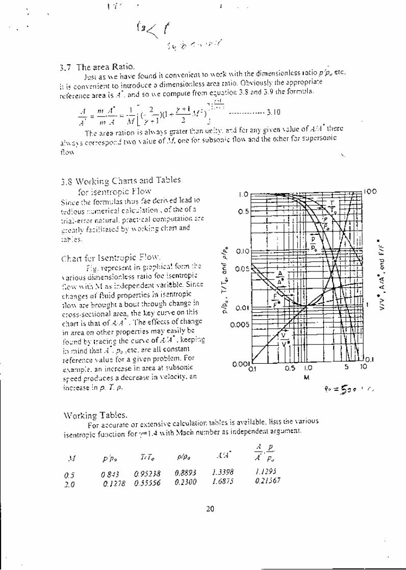
Chart for IsentroPic FIo*.Fig. represent in graphical form the
var ious dimensionless rat io foe isentropic
f lsu, ' l l i th \ ' { as independent I 'ar i lb le ' Since
changes of f lu id propenies in isentropic
tlorv-are brought a bout througb change in
cross-sect ional aiea. the key cun'e on this
chad is rhat of A/A' . The effects ofchange
in area on other propenies ma1'ea.qi ly be
found by tracin-s ' the cun e of ' { l '1 ' , keepi:e
in mind that.1 ' . po -etc. are al l constant
referertce value for a given problem' For
exaniple. an increase in area at subsonic
speed produces a decrease in veloci t l ' ' an
increase in p. f , P.
of A'/A' lheresuperson ic
\-
0.5 r.oM
is avai lable. l is ts the var iousindependent argumeni
1 0 0
o. lto
l " = f t e , r .
{
l \
l L -o.lo,00
\\rorking Tables.For accurate or extensive calculat ion tables
isentropic funcrion for y= I .4 s ith \4ach number as
0.52.0
M p/P. TiTo p/po -4"4
0 813 0 .95238 0 .8893 1 .3398 1 1295
0. t 2i8 0.55s56 0-2300 1.6875 0'2I567
: T\-i" t
Tjp \
4 .\ iIfJI
\ - -v--l 1
L +ih z \
+I
l+
I-|j.t
i , r\ r 't lI I
+ n
20

3.9 Isentropic Flou'in Convergent Nozzle:Coniider a fluid stored in a large resen,oir is to be discharge through a converging
nozzle to region u.here the back pressure Pa is control lable b1' means of a valve. For a
constant resenoir pressure Po it is desired to study tire effecrs of the variations in back
pressure on the rat of mass florv through the nozzle. the pressure distribution along the
passage and on the exit-plane pressure P. . These effect are portral ed graphicallf in Fig,
anr b. and c. respect ivel) .
Vo=P o 'To=
ppo
o ic o n s tcons t
F t o w
Pe
E x h o u s t e r
(a)
PE
Yo
U Pa/Po
(c)
[*-R e gime u --J.- negime I-']
l-.-frp"
( v ) ( i v ) i( i i i )
( i i )
( t )
P B / P o
(b)
Fig. operation ofconverging nozzle at various back pressure'
Ps( v o r i o b l e )
vF
V o l v e
R e g i m eI
R e g i m eII
i )( i iL -
( i i i ) -
D i s l o n c e A l o n g N o z z l e
Regime tr
fi r: -,,
2 l

To begin u,ith. suppose thar Pb/Po= l, shou'n as condition (i) in fig.. The pressureis then constant through the nozzle, and there is no floiv. If P6 is now reduced to a valueslightly less than Po as shorvn by condition (ii), there tvill be florv *'ith a constantlydecreasing pressure through rhe nozzle. Because the exit flow is subsonic, the exit-pJanpressure Pe must be the same as rhe back pressure Pl, A funher reduction in Pt 1ocondit ion( i i i ) acts to increase the f low rate and to change the pressure djstr ibut ion , butrhere is no qual i tat ive change in performance. Simi lar consjderat ion apply unt i l condit ion(v) is reach at u,hich poinr P b/Po equal the critical pressure ratio and the value of lvleequal uni ty. Further reduct jon ln PbiPo. sa1' to condit ion (v). cannot produce lunherchanee in condit ion u i ih in the nozzle. for the value of Pe/Po cannot be made less thanthe crr t jcal pressure rat io unless there is a throal upstream ofthe exi t sect ion ( i t isassumed here that the strea:n f i1 ls the passage). ConsequentJy at condit ion(r ' ) . the pressuredistr ibut ion n i th in rhe nozzle. the v alue of PetPo. and dre f lo\ \ rate are al l ident ical u l ihihe corresponding quant i l jes for condit ion ( iv) . \ \ /hen the f lorv reach the condi i ion thef lou' is cal led to be chocked.
To summarize the proceedir te discussion. the trvo di f ferent t l pe of f lorr r . i i l l .cdenoted as regime I and regi i re I I . These reginres rray be compared as fol lor is.
Ree ime I Res ime I I
c)$'
PblPo > P*iPo
PelPo=Pb/Po
t\.{< 1
Pb/Po< P*iPo
PbiPo=P*/Po
... t;^u r \ l u , ,- independ ent on Pb/PoAe-Po
t i l . , J l o , ,
Ae . f o
3- i 0 Convergent-Divergent Nozzles:Consider an experirnent similar to the one describe, except that a
converging -diverging nozzle is to be used. Fig. With Pb less than Po by asmall amount, the flow is similar to that through a venture passage. and itmay be treated approximately as incompressible. The correspondingpressure distribution is shorvn by curve(i) and (ii) in fig. \\4ren Pb/Po isreduced to ihe value corresponding to curve (i i i). The l\4ach Nunber at thethroat is unity, and no further reduction in Pt/Po are possible if the streamfills the passage. We consider next the operation when the flow is entirelysupersonic, corresponding to curve(iv). The value of Pb/Po for curve(ir')conesponds exactly to the alea ratio ofthe nozzle. Ae/Al, as given byisentropic table( in this case At=A*, since Mt=1). This is often called thedesigrt pressure ralio of lhe nozz[e.
22

tr-, o1,."
P o =
r o -
F l o w
E x h o u s l e rp s
. 'E
V o l v e
'Nof lowpa| temfu l f i l l ingthecondi t ionof isent rop icandone-d imensionalho* "* u. found which-will correspond to values of Pb/Po bet*,een those
oi"u.,r., 1iiil and (iv) in fig. one merhod of finding solutions foe these
Uour]a^,y .o,"tairion is to sr-fipose that irreversible discontinuity involving
entroDv increase occur someu'here within the passage'
AYi
I
%
oD i s i o n c e A l o n g N o z z l e
Fig. Operation of convergine-diverging nozzle at various back pressure'
i-1 1 Some Application of Isentropic Flo*' '
Thrust of Rocket Molor. Rocket motor is generally consist of tlvo parts'
the combustion chamber u'hich is a container where the fuel is bum and the
thrust unit where the thrust is develop' The tbrust unit is almost a
convergent-divergent no777e. The combustion chamber is generate gasses
steadily at a stagnation pr.rru,t of Po and sta*snation temperature of To and
;;;,h'" **, i, J"puna.d isentopically in the thrust unit as show in fig'
Th*e conveiging-diverging nozzle bas a th-roat area of At and exit€r'ea
of Ae. The generaied gase, i,Jutg" to the atmosphere at pressure of Pa' '
Most rocket engine gases at about iOOOpu and operate in atmospheres with
pr"rr"* "f l0i3kP; or less, therefore, such a reduction in pressure is only
iossible by converging-diverging nazzle' The net thrust acting on the rocket
o i
;r;{ -l
z5

-1 :.r 1\ <-=-..--\/2\E.-----/)'
r+-*r > fo l | c - p rassur6lDts t . jbu t ioo
Prodr,.cesPosilive ihrL'sl iP,ore whcre p.,po
'Produces
)
Fie isentopic f lon in rocket moror.
engure nleY non'be obtained b) 'appl l ing ihe r. Ironrentum equation olr t l .refree bociv diagrarls of ihe control lo jurtre.
3 = n t l ' e - . r , e (Pe - Po ) - - - - - - - - - - - - - - - - - - - - - - i . i I
u biclr is then put into dinrensionless for through division bt, poAt.I nr , . .4e Pc Po
€ . _ _ ( _ _ _ _ _ _ - 1 t rPo-lt Po..4t .1r
' Po Po
rolll c
l l l
ed
'C!7
rO
lI
C f l o
2 tl
o\
: )
quailon
lD ^ , 4 a R ' 7 = l
and from the energv equalior) :
t , j ^ ^ , - - - - = - . - - . k , - f , , =
ve - ,J tLp( l o - Ie ) .= r :? .CpTo, ;1 - ; = , lZ .CpTor j ) - (+ ) '\ to \ Pc.,
Subsisting rhese into the thrust equation and reananurns,
Since the pressure rat io Pe/Po depends onl l ,on the area rat io equat ion i . l3 , indicatesthal_lhe trust lor a nozzle ofgiven size and geometry depends only, on po and rhe ratioPe, Po and is independent of the temperature fo.
Effect of Area Ration\ \ , 'e no* ' ask, for ei 'en 'a lue of At- po and pa r i hat e_xi t area should be used in
order to obrain manimum rhrust?. 81, app) ing rhe carcurus to equarion 3. r 3 i t mav beshor 'n af ter a labor ious carcurat ion that s is a maxinrum rr hen the area rat io is c l rosen insuch a *ay to make the pressure in the exi t prane exactJ 'equar to pa. Therfore equat ion3 .13 become.
there re sults.
- -:tt1
S ur loc€
1 t

Perfonlance of Real Nozzle:The performance of real nozzle differs slightly from that computed by isentropic
no* o":ing io the friction effect. Since depanure from-isentropic florv are usuaJly.sm.all'
tha usual iesigl procedure is based on rhe use of isentropic florv function u'hich rhen
, , , o O i l ; . a b y ' e m p i r i c a l l ; " d e t e r m i n e d c o e f f i c i e n t ' T h e s e c o e f f i c i e n t a r e t h e n o z z l ee ffi ciencl' and the nozzl e di scharge coeffi cient
The nozzle efficiencl' T1\ ma}, defined as the rate of the erir kjnet;c energy to the
k i n e t i c e n e r g l , r r h i c h m a l b e o b i a i n e d b l . e r p a n d i n g t h e g a s i s e n i r o p i c a l l y ' t o t h e s a m efinal pressure.
l ' - ' )
' ' 1 ' 2
------------------------ i. I 5
The nozzle discharge coef i lc ient Cd is def ined as
the rale of the actual nlass l lo\ \ rale r)r lo the riscnrroFic:rass f lorr rale / / r , rc \ \h ich rrould be
obrained b1 erpanding the gas isentropical l f io
the same f inal Pressure"' '3 16Ld = - -------
n1t , t
The figure at the right hand side sho\\'s the
isentropic and the real expansion Process through
ihe nozzle. \\rhen the first larv of thermodl'namic
app); . ' ing at the expansion process for both isentropic and the real process.
2;e
___ Tc
T i
I t 7
- 7 .J o ,
and h=cr .T , there fore
and for isenrropic process t
= , ,,--r.t
/ therefore ,
I p r ] lr ' ; . , ' =2,0.r .1 l -( ; ) ' I
- --------------3.17t ' - J
simi lar ly one rnighiconsider the imaginary isenrropic process between the actual exi t
state and its slagnalion state oe.
v ?h,," = h.-+ and h= cr.T , therefore
v"' -- 2." , .r*1t -
l l ^ofor isentropic process
* = ,hr: rherefore '
25

T ^ . ' -L lv,' =zc-.r,-lt-rt,,
l- 3 . 1 8
The process u i rh in rhe nozzle is ad iabat ic rh is mean that To,= To" , subst i tute equat ion 3. i 8and 3 .17 i n to equa t l on 3 .16 and s imp l i f l , i ng .
p I P r l ;' ' = l l - n . ( ) - { 9 - r ' 1 - - - - - - - - - - i . 1 9P", L
'P. ' l
The mass per uni t area for isentropic l los,can be evaiuated as a funct ion ofpressure rat ioinstated of \Jach \umber. j fone c:n subst j tute equat ion -1.5 jnro equat jon 3.7.
. ' - - ^ ; ^ : ^ r - r -
" ' ' , = p - ! t - t l rL t ; - r l - t f : - - - - - - - - - - - - - j . :0. - i
' " \ R T \ . / - t l ' P , '
' P , , '' I
Simi lar lv the actual mass i lur nrar be obtain.
a .' t - , : , t ; : ) , r , , :
: - ' ' r , ? r i , . . - r ] ' t l' ' r " " 1 . L .
Subs t i t u t i ng equ : t i on 3 .1 l . i . 2 0t e r ; n n f n rpcc r ' r , . r r r i ^
P ----: P :---/ ' r , l 1 1 / _ . \ '\ p ) i ' - \ p )
C d = " ' : : ' -
,p t:: tl p t1
( - - r ) ' l t l - t - 1 ) /f," I r",
Subst i ture equat ion 3. l9 into the above equat ion to f ind rhe discharee coeff ic ient in termofisotropic pressure ratio and nozzle efficienc;,.
----------------------i 2i
P R O B L E M S
.,3.1] . -d i r l lor rs at the rate of I kg, ls through a convergent- d ivergent nozzle- Theentrance a-rea is 2 X 10⁻³ m2 ard the inlet temperature ard pressure a-re 438 Kald 580 kPa. I f the ex i t pressure is l4O kPa and the expansion is isentropic ,fin cl:(a) The veloc i ty at entrance.
o n J . I o
, r , , ; i- l -:*.r I
i r i i o equa l l
---------------i.: l
: o f i nd t5e g i scha rse coe f f i c i cn r i n
l p r i1 - r . I l - ( r ) ' I' ' | p i\ L l
2 0

, k eC-,-
-A.3ri
(b) The stagnation lemperature ar|d stagnation pressure-
(c) The throat a.nd exit areas'
.- -. (d) The exit velocity'
3 .2) a .onu"rgent nozzle has an ex i t area 6 '5 X lO-a m?' Ai r enters the nozzle at-tt
oo : ito iPa, l"o : 370 K' If the flow is isentropic' determine the mass rate of
fltt*' fot back Pressure of:(a) 359 kPa(b) s4O kPa(c) 2OO kPa.A convergent-divergent sleam nozzle has a-.l exit area of 3'2X l0-a m2 and a:r
;il;il" "i ilo tp. The inlet concitions are I MPa and 590 K \r'ith
".gf ig iUf. veloci ty. Assume iCeal f lo*" i e ' no )osses' and
- : u . - \ . 4 )
'1j
Finci:(a ) Tbe mass ra te o f f loq fo r th is nozz le
(b) The th roa t a rea .
(c) The sonic \ 'elocit.v al the throat
A i r f lo \ . ' s i sen t rop ica l l y th rough a corvergent -d ivergen l passage w i th in le i a - rea 5 2
i l ! , ' - t " t -"- " i " ̂ - l z.nf ind exi t a 'e" 3 87 cm2' At the in let the air veloci t f is
;ob';;, pressute is 680 kP a' and temperature 345 K' Determ jne:
(a) The mass rate of f low through the nozzle
iui rr,. N{ach number at the minimum-area section-
i . j f f t " re loc i ty and the p. ressute at the ex i t sect ion '
Air is flo*ing in a convergent nozzie' At a Part'cY l-"I-1""*.t"," within the nozzle the
;;.r;" is Z-aO tpa, tbe steam temPerature is^3-45 l<'.and the veiocitv is I5O m/s'
I f the cross-sect ional area at th is locat ion is 9 '29 X l0-3 m2' f iDd:
i"i ir," Mach number at this tocatio:l '
iui rn" stagnation temp€rature and pressu;'e'
l;i i l; ur"-i pr"rtut"' ' "nd temPerature at the exit where M: I o'
ial rr'" mass rate sf flew for the nozzle-'
Ind icate any assumpt ions you ma-r- rnale anO lhe source o l data used in the
sotution. f/) I
A i r f lo* 's isentroPical ly at the rate o i0 5 kg ls through a suDersoDic convergent-
divergenr nozzle. At the inlet, the pr"ssure is 6-80 kPa".the temf",|i*J9i K'-^nci
irr"li". J e .s cmz' If the exit area is 13 cm2' calculate:
(a) The stag!ation Pressure and temperature'
(b) The ex i t Mach r , ru1q€r . , - .1 .
(c) The exit pressure and tempeiature' y,) r^ a' I " ,,. , -.-?
iai rr," area and the velocity a! rhi thr-o+'- ------^-,,-^ --,, lu^.,
(e) What *'i l l be tn:e -"irn"t raie of'Gw and the corresponding exit Mach
number if the flow is completely subsonic in the no-zzle?
i l, 3,7. A stream of carbon dioxide is flowinc il;Ll*n I'D' pipe at a strean pressure or
) 680 kPa and a stream itrnp"'"t"t off$' A 7 5 cm X 5 cm venturi'neter- - )
t ; i l ; in- i r t i , p lp" shows a Pressure dr l 'erenr ia l reading of 1 '68 mm Hg
Assuming ideal f low, determp' \ . - r ̂ L^ . -L . - : -^ , i r ,ha(a) The mass rate oinot" of
-C-O'l Compare your alswer $ith that obtained if thr
' igit i. considered incomPressib!-
- } �J . 5 . '
/5])),1-:"/

(itt " r ' i \
\ I R
-3,.19,t
(b) If the mass rate of flow of CO2 were to be doubled' what would be the oew
pressure differential reading for the lenturimeter? .. .(c) i f r i ,e f lu id were hydrogen instead ofCO2' other condi t ions being the sarne as'
given in the problem statement' \r'hat *'ould be the mass rate of flow?
(dl i f the temperature of the CO2 were 440 K instead of 365 K' o ther condj t icns' - ' l " i r r g , n " s " * " a s g i t e n i n r h e p r o b l e m s t a t e m e n t ' $ ' h a t \ r ' o u l d b e t h e m a s s r a t e
of flow for the CO2?
A 0.14 m3 tank of compressed a i r i ischa ' rges through a 2 2 cm diameter
"."i ".gj.g "ot.le located in the side ofthe tank' If the mass flow coefTicient ofrhe
".lt:"-Uri"a on isentropic flou' through it is 0 95 and thc gas v'ithin rhc lar:k
"*punat isothermal)y f : -on I MPa to 350 kPa, p lot the pressure in the tank versus
el ipsea t lne as rhe pressure dec:eases Assume tbe temperature of rhe tank is 295
K a.r td t j re surrounding p:essure is l0 l '3 kPa'
Ai r a t sragnat jon condi t ions of 2 l r {Pa ard 750 K l lo$ s isentropica i l l ' rhrough a
con. ergilldiu:ergra g nozr-l!. If the ma-ximurn flo\r' rate rs 5 4 kg/s' detemrne:
(b) The at the nozz le ex i t i f rLe ex i t a rea is
3 . 1 0 . . ' F i n d t h e t h r o a t a ' r d e x i r a r e a s i n m ! f o r a c r i t i c a l - l l o r v n o z z l e h a n d l l n g
lelocitl ' .i imes as
pressure , and t emPera ture
le rge as the th roa l a rea .
a i r a r t h estrealTt el
,r'.r:,:..,
t ' ' ru" - " l i l kg ls * 'hen rhe desi red exrr le loc i t l is I I oO m' ls \ r ' i th the
p - : ) i O k P a a n d I : - r l O K ' A s s u m e i s e n t r o p i c f l o r v a n d ' l : t 4 '
: . t t l ) a i r f lous rev-ers ib ly and adi4bat jca l ly in a nozzle. At sect ion I o f rhe nozzle the
, ' ' r 'e loc j t ] . pressurer , . -p l i ' iu t t , and zrea are 165 r s ' -150 kPa' 460 K' and
l t t lO- i m:- At sect ion 2 in nozzle the a- 'e a is 26x lO*1 m? Fin&
(a) The mass i low rate i ! the nozzle '
(b) V2, M2, Pa, t2 and '7 ' | ; " ' r
i,ltl". ' 1it,.t" are t*'o in*pendent arsu'ers for this condition' Calculete both
cases. If there is a 1fuoat' determine its area )\ \ J \ r ' o
^ . a 7 a \ a - - r - . " " - a - r ' p r o i r o -f -12. ,Ai r a t a pressure o i 680 kPa and a ternperature o i 833 K enters a converg ing
.-. - ,.t dir,.rging nozz le through a line of 4-6 X lO-3.m2 area and expands to a delivery-
,*g io i p i " r rur . o f 33 kPa- Assuming isentropic expansion and a mass rate o i f low
of I kg/s , f inc(a) Tbe stagtat ion enlh a lPl '(b) The temPerature and enthalpy ar d ischarge '
/ i4 Tne Mach number and veloc i ty of the a i r s t ream at d ischarge '
l / . Ld l The ma; i imum nass f lo* rate per unj t ar€a
t i ; , i " f lo* 's isentropica l ly at r l re rate of I lg /s through a duct- At one sect ion of the / \ , )- ' t '
O r a a t ' l t " c r o s s - s e c t j o r . a l a r e a i s - 9 1 Y i 0 - 3 m 2 ' s t a t j c p r e s s u r e i s 2 O O k P a ' a : l d r ' \ n
- : - , - r * r , -n temperarure is 5 iO K. Derermine the 'e loc i ty of rhe st re-a-rn and lbe
mi, i imum area at the ex i t o f rhe ducl rhat causes no reduci icn in rhe mass rate c f
( i ;,/>
flR*. >:Air llows isentropically through A i6nverging nozzl-elAt the inlet of the nozzle the
pr" . r r r "pr : :ab tpa, the tempirature I1 is 55-0 K, the ve)oc i ty Z1 is 200 m'us '' . t
d ,h" . ror=-r"c t ional area,41 is 9.3 X l0-3 m2' Consider a i r to be an ideal gas
\! ith y : I .4 and find:(a) The stagnat ion temperelure and pressure '
iUi fh" sonic ve loc i ty and the Mach numbet at the io leL
(c) The area, Pressure, lemperature, and !e)oc i ty at the ex i t i f 'L | : I a t ex i t '
o ' \ t

t
J-6(d) Draw graphs of G, M, 4 aad./ vcrsus prcssurc, indicating the values at the
inlet and exit of thc nozzlc.3.15, Superheated stcam expards isentropically in a. convcrgcut{iverge_lrt- nozzle from
a-n initial state in which the pressurc is 2.O Mpa and thc superhcdt is 37g K to apre5sure.of 680 kPa The rate of flow is 0.5 kgls.(a) Find the velocity ofthe steam and the crosesectiooa! aJea ofthe nozzlc at the
sections where thc pressures are 1.0 Mpa and 1.2 Mpa(b) Determine the pressure, velocity, and crosssectional ares at the tbjoat.(c) Determine the vclocity ard cross-sectional area at discharge.
Assume 4 : o.r r .Po
3.16. A convergent nozzle receives stcam at a pressure of3.4 Mpa and a temperature of640 K with negligible velocity. The nozzle dischargcs into a chamber ar which thepressure is mainta ined at 1.36 MPa. I f the throat area of the nozzle is 2.3 X l0-1m2 and the discharge charnbcr a-rea is 0.056 nt', find(a) The velocity at the throat.(b) Thc mass rate of flow.
^',Assumc a : 0.55 and the flo*, is isentrooic-
Po3.1 7. Air flows isenrropically rkough rhe convergent-divcrgenr nozzle shown in Fig
3.24 The inlet pressure is 80 kPa, the inlcr temperature 295 K, and the back
4 . 1 . 0 c m i ' "l a "
FIGURE 3J1
pressure l.0l 3 kPa. What should be the exjt diameter of tie nozzle whichcorresponds to the maximum obtainable value of Mach number at the exit? WhataJe the mass rate of flow, the exit Mach number, a:rd the exit temperature?
3.18. A rocket motor is fitted with a convertenr-divergent nozzle having a throatdiameter 2.5 cm, If the chamber prcssure is I MPa and thc chamber temperatureis 22OO K, determine:(a) The mass flow rate through the nozzle.(b) The Mach number at the exit (ps..1 : 101.3 kPa).(c) The thrust developed at sea level.Assume that the products of combustion bchave like a perfect gas (7:1.4,.R: 540-J/kg K) and the expansion through tbe nozzle is isentropic.
3. I 9. Air is flowing through a section of a straiglt codvergent nozzle. At tlte entrance tothe nozzle section the area is 4 X lO-3 n?, the velocity is 100 m./s, the airpressure is 680 kPa, and the air temperature is 365 K. At the exit of the sectionthe area is 2 X l0-3 r#. Assume reversible adiabatic flow. Calculate themagnitude and direction of the force exened by the fluid upon the gjven nozzlesection.
i.',rl ; ''.1, 't \
I t
i l. i "
Chapter Four
Introduction:Normal Shock Waves
The shock process represent an abrupt change in fluid properties, in which finite bAryvariation in pressure temperature and density occur over a shock thickness comparable to
' "'
the mean frie path of the gas molecules. Ir has been established that supersonic flow ^.adjust to the prissure ofa body.by mean ofsuch shock wave, *'hereas subsonic flow can \"''
adjust by gradual change in florv properries. Shockimay also occur in the flow through 1^:)
nozzle or duct and have a decisive effect on these flqw.
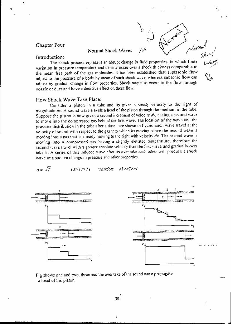
How Shock Wave Take Place:Consider a piston in a tube and its given a steadl velociry to the right of
magnitude dv. A sound wave travels a head ofthe piston throuSh the medium in the tube.
Sufpose the piston is now given a second incrernent ofvelocity dv, casing a second wave
to .ou. into the compressed gas behind the first rvave. The location of the wave and the
pressure distribution in the tube after a time t are sho*tt in figure. Each wave travel at the
velocity of sound with respect to the gas into which iS moving, since the second wave is
moving into a gas that is already moving to the righr with velociry' dv. The second wave is
moving into a compressed gas having a slightly elevated temperature, therefore the
,..ond *,uu" travel with a greater absolute velocity than the first wave and gradually over
take i r . A ser ies of th is induced *ave after i ts over take each other wi l l produce a shock
\\ave or a sudden change in pressure and other prope(ies
a € l t T3>72>TI therefore a3> a2> a I
Fig shows one and two, three and the over take ofthe sound wave propagate
a head of the niston
$t
o
"tf' t
/b/?tJ\
)rv
30

Chapter FourNormal Shock Waves
t;a c c \ ! t T3>T2>TI therefore a3> a2> a l
tto"o?itlXt:"k process represent an abrupt change in nl'1.00':f;"*.;rt:;g;:$ilt::
variation in pressure temperature and density occur over a shc
*:r"#,'l:L::[$f''3*I'"iffi :tl$Ult'1"*it'T*"'ffii:):: :1 iJ:i :li..l1T; il"l';'. :"; ;;,r' ",. n o*
""* T"""",ToY?;,Il5"':':'t"uu. una it'. 'i*l "'.::1*nh'il#oll,"'1i ;:iili*ugnt,iJJule*i:11:i:::i1""'';:"XTi"'.:"'l::iT!If l*f;:TfiiJ;:XT*:?::J'J;;: iit'f i:iti+i{l tr'.ff :Tl *j j;:: ;:tt f U" i"r *".. i.". a ",,r, "
l':*:f iil";t*.:l,:":n'."^'ffi ffi qist1$::;*:;*":::*;ru1:il"f i;;-"=;."::"..1t,i#J;:',.ffi ,''i:",ff ":",T"T#?Ji:'"'fi lirlJffi:ii-l';;[i:"1,'liin'ioTi.o rvave after its over take *"i,'"ir'"' *ili priduce a.shock
wave or a sudden change ln pressure and other properties'
W
Fig shows one and tw<i, three and the over take ofthe sound wave propagate
a head of the Piston
30

t"'t'l:?,#,H:[]::,I.fffi ughastationarvr:i,1t,1,"i,],lJi;,"."""i'ilii.,
rm*ll$**:*:t*:m::r,ii'"Ti+:liiilff*;;1:''*#*:il""",.*",i"" of mass, momert:?,i:1:TtJ,f"l* i?liiili;;iv,"t,.,ipi "'" *aWe rvill refer to the ProPenles '
downstream bY "Y"'
2 i =p ,V ,A ,=P :V iA l
The shock *'ave thickness is very small therefore l':'{' '
- r / - ^ L/ -------------- '
c ^ . ^ a . € P . t o 1 l \r v r f i ! ' r ! - . - - _
=l-r,^F^+ --"'-'4.7in the flor'v direction are the pressure
4 . 1
Since the onl l ' force act ing on the control volume
force, consenation of momentum ls'
P,A, - P,-A! = m'(V, -V')
Combine of equation 4'1 into the above equation' rvhere m' = p'V'A- = P'V'A'
P, + P,V,2 = P, + PrVrt -------4'3
For perfect gas P= P R'-T
P ,+ p ,V ,2 = P , (1+7M, ' )
P,+ p,V,2 = P,( l+lM, ' � )
P,(l + rM,'� ) = P "(1 + /vI t'� ) ----'--'----4'4
The florv through the control volume is adiabatic and the energy equation become'
' ,r, *l -- ' ,r, *vi =co + r' For adiabatic flow the stagnation temperature does nit
.hung" ulros the shock wave this mean that To*=Tov '
r. (r + | v'=, = T,(t + * M,r' ----------------4'5' ^/.
Substitute energy equation 4 5 and momentum equation 4'4 into the continuity equation
A . )
;Jfi;*;a^ io "uia"nt tr'uto; ';r*ion +'o is the trivial one' M'=M' This solution
;i;i;i;;;;il-c' in p'opttti"' in constant area flow conesoonding to isentroptc ltow
and that is not of interest '"' tn" i*"*t;Uf " tinotrnut shock' -Equation
4'6 can be solve
Oisco.rli-
YRT,
to yield Mrin term of M''
3 l

l i ')M " + -
Y - ll{.' = -# -'-----------------4'7
' z / , r 2 1_ l v t r - L
y - l
Norv to find the pressure ratio after and before the shock, substitute equation 4.7 into
equation 4.4 .
P 2 / .V - ' � - 0 -D__LP v + l
alio to find the temperature ratio aller and before the shock, one may substitute equation
4.7 into equat ion 4.5
- v _
f, _Eryi_ o:t:y:!v) --------------4,9
and if *e substitute equation 4.7 into equation 4'l we can find the density and the
velocity ratio.- . ' " t t 2p, y . t r + L) tut t _ -___--____--____-- ,+.10-- - : -=:=-- - ' -=
p, Vy 2+(y-1)M,-
The ratio ofstagnation pressure is a measure ofthe irreversibility in the shock process. It
may be found bY observing that:P P P P' o v - y
"
, = p p P1 y . r . a x
Now f/e is given by Eq. 4.8, ind P"/Prand !/P."anay be found lrom Eq'3'5' Using Eq'
4.7 forihe val-ue of ,41, we get after algebraic simplification'
T, (y +1)M,' �
(y +t)M,'�,Lf-l
-------------4.1 I2+(y + l )M, ' �
To evaluate the entropy change across the shock, we employ the perfect gas formula'
P f t .| t s l r t .
P^ l r+t
s,-s, =c, nl-nnLsubstitute Eq. 4.8 and 4.9 into Eq. 4' 12 then'
%-! = #"1h, ; - #). ̂^l#51 - " "
- --.1- rf - l | ' t l
/^l L
4.12

Impossibility of a Rerefaction Shock
Carfut study of Eq'4 12 indicate that for gases rvith
l<t<1.67 the enrropy change is ahi ays posi t ive when Mx is
nr*ut. . thrn un;ty, ina is aluays negat ive when iv l ' t is . less
i t run uni ,V. The general fom of Eq 4 12 is shorvn in F, ig ' I t
ir or*"".ig-""sly that for perfect gas only the shock from
,ui"*oni" 6 subsonic is possible Since the shock process
i, lAiuUuti. and according to second larv of thermodlnamic
the entropy change must be posi t ive
io*pur ing Eq. '1.12 for entropy change and Eq 4' l l
for stagnation pressure ration' one can conclude the
fol lowing correlat ion:c - e P
R P.,
According to the second lalv of thermodl'namic the rate ofchange'itrO , u""a referring to Eq.4.l3 this mean that P'r' is less than P"
Theshock rvave takep lace in .o rde r tokeep the f l o rvcon l i nua t i on th i smean tha t the f l owi, ,t*dy and the mass flolv does not change across the shock'
m t = n 1 . ,
we have seen lrom the previous chapter that the marimum mass fl-olv rate can be
,.ii.r"a at the chokediondition ani rhe mass flow rare in term of stagnation propertres
and the critical area is.
I
of entropY is Posir ive
Po,-< P* this mean that A'r'A',Po, A* r :Po, A ' , or
M, M) P/P, rr/r, P/P' P'r/P"' or A"/A'Y
"7sr;i
.i, e*' l -
l li f'J,
: V: l a
o i
P A - 'conslant PorA, constant
l f t l! j o ' \ - o Y
the florv through the shock is adiabatic therefore Io'=I',
S l l l \ . E
)
Normal Shock Table:Tableisavai lablewhichl ist therat ioofthevar iousf lorvvar iablesuchaspressureJ
temperature , and density u"'o" th" no'tul shock wave and the downstream Mach
Number as a function of the upstream Mach Number'
-lJ

Convergent-Divergent Nozzle:
weretumnowtotheproblemoftheoperatingcharacteristicsofconverging-diverging;;;;;;;;.;rru."'ru,io, discussed previouslv in chapter two' Frg' show the
;;;;;,;;il;;rfo.mun.. of converglnt divergent nozzle with various back pressure to
the supplY Pressure.Four different regrmes are possible ' In regime I the flow is entirely subsonic' and
thepassagebehavel ikeaconvent ionalventuretube.Thef lowrateissensi t ivetochangein back pressure. At condrtlon 2, which forms the dividing line between 1 and 1l the
inr.J NirtU", at the throat is unity' As regime 11is entered' a normal shock appears
a"",, ,t*", ofthe throat, and the process aft ofthe shock comprises subsonic
;;.d*;,i;;. As the back pressure is lowered' the shock move dorvn the nozzle until' at
"""ajii"i + it' appears in the exit plane ofthe nozzle' In regime 11' as in regime 1' the exit
;;;; ;t;r;" F; is virtuallv identical with the back pressure P6' on the other hand' the
florv rate in regime 11 is constani and is unaffected by the back pressure' This is in accord
IPo{ConsL)To(Const.)v"'9
t oErhdJstet
eu/ro
(b)!" / 'o
(c)
-.+**F7 6 5 4 3
\.l n 9 a o
z\!\
gtfgo
(d)
with the fact that tfuoughout regime /1 all stream properties at the throat section
are constant' :ntire nozzle is supersonic'
In regime .11L As for condition 5, the flow within the t
"na tfr. pr.ti".. in the exit plane is lower-than the back pressure' The compression which
ililffiil;."" ""*fai, the fiozzle involve oblique shock wave which cannot be
treated on one-dimensional grounds' Condition 6 is termed the design condition P-t t".'#i" ,"i"r'r"p."""r" *niition, since the exi'plane pressure is then identical with the
;ffi'!..",;;;". i reduction in the back pressure below.ihat corresponding to condition 6
has no effect whatsoever on the flow patte-rn .wi-thin the nozzle ln regime I/ the
;##;; ,h. "*it-pl*" pressure to'the back p-rbssure occurs outside the nozzle in
{a) Curves of pressure versus djstsoce along nozzle axis'
iu) Edt-p)ene Pressure verstls bsck preseur€'(c) Tbroat pressur€ versus b&cx pl€tl3ure'iil frl"t" A,j* pBrsrDet€. versus ratio of back pr€deuro to supPly
0islonca Along Noz2l8
(a)
Po
Loctls of / -\.
Stotes Down9tr6omof Normol Shock
34

the form of oblique expansion waves which also cannot be studied by one-dimensional
analysis.- -
' In both regimes III and IV the florv pattem within the nozzle is independent of
bu"k pr"ssur", ani con"rponds to the flow panem for the design condition' Adjustment
to the back pressure are made outside the nozzle'
. For subsonic flow, there are an infinite number of possible pressure. distance
au.uar.port t . .up".roni" t"gionoff lorv,holvever, thepressure-distancecuryeisunique'i" p", it differenily, in subsonic florv the pressure ratio does not depend solely on the
ur"u'rutio; in supersonic flow the pressure ratio does depend solely on the area ratio' . .Only over a narrow range of back pressure ratio, namely' the range covered b'v
,.ni." 1, does the florv rate depend on the back pressure' For regime II' iil ' M' the floir
t"i. if i"a.o."a-nr-of th. back'pressure' since '11= i at the throat' may be computed form
choked florv equation'
Converging- Diverging Supersonic Diffuser'- ; di"ffuser is a dlvice that cause the static pressure of a gas to rise while the gas is
a.".t.ruting. When deceleration is isentropic, the maximum pressure that can be attained
is the iseitropic stagnation pressure. Diffusers are ei!her subsonic or supersonlc:
i.p""ai"g "^ it," t,tuJn Number of the approaching stream. In a subsonic diffuser the
.ror.-r".iionul area increases in the directlon of flow, while in a supersonic diffuser the
cross sectional area first decrease and then increases'- "-- t sup"rronic diffuser is located at the inlet to such air-breathing engines as, the
superson ic tu rbo je tand the ramje t , .Theh ighve loc i t ya i r i sdece le ra tedby thed i f f use rU.?o." it is compiessed in the axlal florv compressor of the turbojet or belore it under-eoes
combustion in tire ramjet. An ide'al supersonic diffuser consists of a convergent-divergent
;;;;;*", in which ih" flo* is shoik-free and isentropic. Deceleration of the flow to
ilfi;il,il."i ii ioiio*.d by a further deceleration to subsonic speed downstream of
,; ih.";. In real application, however, starting transients and off-design interfere _in.ri"urirni"g the desir'i flow pattem. The maximum pressure that can be achieved in the
diffuser is ihe isentropic stagnation pressure. Any loss in available energy ( or stagration
o..rru,"l in the diffuser wiil have a harmful effect on the operation of the engine as a
;;il. i;; u sup"ooni" diftuser it would be highly desirable to provide shock free
isentropic flow.'--' --To. any configuration of the converging-diverging diffuser, there are two values
of Mach nu*b", in *Ihi.h th" flow is isentropically compressed, this wilt called subsonic
a"rif ft4u.f-, number( Mp*6 )and, supersonic design Mach number(M2*o)'The following
."r.i * r show how the flow is eitablished from the starting-up to the design flying
Mach number.' --- i_ wt.n the flying Mach Number is below Mp*6 value, this mean that the acrual
throat area is grater than the critical area, therefore the flow at the throat is
subsonic and thi flow is continue to compressed at the divergent part as show in
{ i c r
,- Wil; the flying Mach number reach the MDeb value' this mean that the actual
throat area is equal to the critical area ofthe flying Mach number' rherefore the
flow at the throat is sonic M=l and the flow is continue to comPressed at the
divergent part and the exit Mach number will be subsoqic fig'b'
35

-'-\.
-)- When the flying Mach number is grater than Mp*6 vdlue, this mean that the
actual throat area is less than the critical area this mean that the throat area is too
small to accommodate the flow. The pressure is iristantaneously increased at the
throat area and part of the incoming fld4v is divert or spill over rhe inlet cowl of
the diffuser as show in fig.c This mean that as the flying Mach number increase
the different between the throat area and the required area increase and hence
mass spill over is increase.
Wl-ren the flying Mach number is grater than one but is less than the Mo',, , in
this case the throat area is less than the critical area or the required area to
accommodate the florv. Therefore the instantaneously pressure built up at the
throat area. A curved or normal shock is appears in the front of the diffuser
inlet. The subsonic florv downstream ofthe shock is partially spilled over the
diffuser inlet, reducing the mass flow through the inlet, this rvill lower the
combustion pressure and a loss in thrust.
When the flying Mach number is equal to the Mp"uo value, in this case the
existing of the shock rvave will caused of stagnation pressure loss. The critical
area behind the existing shock is increased and this mean tiat the critical area
upstream of the shock is equal to the throat area but the area dou"n stream of the
shock is still grater than the throat area. Therefore the normal shock is still
existing and the flow spill over is continue as show in fig. d.To over come the existing shock the engine have to speed over the design
supersonic Mach numbqr until the shock located at the diffuser inlet. At this
case the Mach number down stream of the shock wave is equal to the M2-6 so
that the mach number at the throat is equal to sonic. A little increase in speedwill make the shock wave to swallowed and stand at the divergent part of the
diffuser as show in fig. e.To retum back to the design condition the engine have to slow down to the
desigr supersonic flying Mach number, in this case the shock wave is drawn
back toward the throat and it strength will reduce gradually until it vanished at
the throat when rhe flying Mach number is equal to the Mp* as show in fig.f
n
o-
n
",.^'l*-l\ ^ r , /
_. -f Mdr
/t-_;;\. / ^ . ' > ^ n \
?: n',.- M<l
i,-a;.i;\
*-*s\{*
/-qMrjreg \-.-:---'l*,

P R O B i E M S
4.1. Air with initial stagnation conditions of ?0o kPa and 330 K passes through. a
convergent-diverge* ""J" ttii" t"" of t fgl"' At *t" exit area of the nozzle the
,t"gnrion pr"*uie is 550 kPa and the stream Pressure is 50O kPa- Tbe nozzle is
insulated and there is no irreversibility exc€pt fcir the "t:g:".n* of a shocL
(a) -What is the nozzle throat area? - - '. .
. ' -- l'::--l :'"'
(b) 'what
is th" M";;;;;' i"i.* a"q4t $e s,|9-c5i:: '" :6ic) Wfrat is rhe nozzle area at the point of shoek and at the exrtj
ia; Wt"t is the stream density tit the'exit?
,,-q.2. I'pealstcqs (r: t.+i "o*o " "onuersinq aivlJiilgnoSrre ltfr-a Macl:ybj'of 0.5O and.local pressure and temPerature values of 28O kPa and 280 K'
iespectively. The nottl" rhio"t area is 6'5 X lO-a m2 and the nozzle exit area is
26x 10-a m2. The nozzle exit pressure is l?0 kPa'
(a) What ale the values of the Mach number and the stream temperature at the
exit?(b) At what area does the shock occur?iho* you, method of solution on a skeleton flow chart'
An air nozzle has an exit area I '6 times the throat area- If a normal shock occurs
;;;oi;;" where the area is i'2 times the throat area' find the pressure'
i"*p"Lt,r.", and Mach number at the exit' The stagnation temp€rature and
pr"rrur" before the shock are 310 K and 700 kPa'
Air €nters a suPersonic n627ls with inlet conditions 4 : 6'5 X l0-4 rrP''ii
:'1-.e, pt : is kPa, and Tt : 260 K' A normal shock occurs in t}re nozzle
resulting in an increase tn entropy of As : I l3 J/kg K' If the Mach number at the
.. 4.3,.
.t4.4.
exit jl{z : 0.3, find:
(a) The area of the normal shock l" '
iti frt" Mach numbers before and ifter the shock M*' Mr'
(c) The pressure at the exitp2.(d) The mass rate of flow Per unit area at exr!'
(e) Show the process on a schematic {low chart and a FanneRayleigh plot'
Assurne isentropic flow except for the normal shock'
4.5, An impact (stagnation) tube in an air stream reads 186 kPa' If the local
i"tnp"o,"t" L zbS r'-a the local Mach number is 0'8' determine
(a) The local Pressure.(b) The mass rite of flow per unit.area'
4.6. A Pitot tube and a thermocouPle give the lollowing measuremeots pertaining to air
flow in a duct:
Po : i80 kPa' P - l5 '1 kPa' Io : 1250 K

la ^- . .
-\4oving Shock Wave:-Previous section have dealt rvith the fixed normal shock wave. However, many
physical situation arise in rvhich a normal shock is moving. when an explosive occurs, a'ihock
propagates though the atmosphere from the point of .the
explosion. As a blunt
Uoay ..-"nt"is the atmo;phere from space, a shock travels a short distance a head of the
booy.rvnenavalveina-easl ineissuddenlyclosed;ashockpropagatesbackthroughthegas. To ireat thbse cases,-it is necessary to extend the procedures already develop for the
f iced normal shock wave.. consider a normal shock moving at constant velocity into still air as show in fig.
Let Vs= absolute shock velocity and V5 velocity of the gases behind the wave' both
velocities are measured \Yith respect to a fixed observer' For a fixed observer' the florv is
n o t S t e a d y , s i n c e c o n d i t i o n a t a p o i n t a r e d e p e n d e n t o n w h e t h e r o r n o t t h e s h o c k h a spassed over that Point.
Norv consider the same physical situation with an observer moving at the shock-
r.vave velocity. a situation, for instint, with the observer "sitting on the shock wave". The
shock is now fixed rvith respect to the obsen'er as shown in fig But this the same case
already covered in the normal shock section. Relation have been derived and result
tabulaied for the fixed normal shock. To apply these result to the moving shock'
consideration must be given to the effect of observer velocity on static and stagnation
DroDerties.
v;V ' = Q
v; v, v , = V ) - v ' , v , - v ; - v :
{s} l t lovirg,*are
Since static pioperties are independent of
transformation of the coordinate system has no effect
properties on the other hand depend on the observer
attectea Uy the choice of the coordinate system' Table
coordinate system and i a moving coordinate system'
{b} Statiorrary rvar e
the observer velocitY, theon static prope(ies. Stagnationvelocity and consequentlY are4.1 show properties in a fixed
37

TABII {.r
S/6ic prdperli$i
o - - p ' - -
t " = € i
.;rij*.*
]fach autuM.sl
vi t1- v"u, - ; - -1
T/'r Vi . Y,r{',:; =--:-
Sragn4li{�a /ro?ei;.ti
/ r - r , \r o , = r , \ r * 2 l r )
/ v - t - \ro . , - : r r
\ r * ;u i )/ _ _ r \ r 4 r - I '
""-- o" I t +J-i ul I, * . - \ : /| - - l \ Y " t l - r )
n o , - o " l t + - ; : u ] lt t
, , - f , - l r
Mt." ^ =---.*
.t ,,
ri t', - vtM i ' ; - "
7"8,'r'
pb|= P;
Pdr - Pi
( ' r?* ' )I t - t - \l t ' , M i ' l
( , , ' - ' . r ' , \ t " ' - "
\ ' z " ' J
I t - l - \ Y ' ( r r ,
l ' + 2 ,4 t ; ' /
' 1 l
\\hen a normal shoik wave travels in a closed-end. the gas between the shock wave and
the closed end remains at rcst' The gas behined the shock, however' moves at a velocity
vy' as shoo,n in fig. The incident shock is reflecled at the closed end ofthe tube and
piop"gut., back through the incoming gas. For an observer moving with the wave the
i,.iJ"liy upp"", us shoin in fig. Since the gas velocit-r' decres across the reflected wave,
the incide;t shock wave is reflected at tbe end of the rube as a shock rtave'
lDcjcrFnt
Eeilect.d
{.} Va}ecili6 rehriv! tor firgd cooaciirstetyl8!.rl
{bl Velocitils .dsiv!tg r Syrttrr rngyingItith th. rEr
r_* v:
38

Chapter 9
7-1 T-17ranno r rcw
9. "1 INTRODUCTION
At the s tan of Ch3prer I lve mentioned rhat area changes, friction, and hear trans [er arethe most imponmt factors affecting the propenies in a flow system. Up to this pointwe hal e considered oniy one of these factors, that of variations in area. However, wehave also discussed the various mechanisms by which a flow adjusts to meet imposedboundary conditions ol either flow direction or pressure equalization. We now wishto take a look a! the subject of friction losses.
To study onll the effects of fricrion, we analyze flow in a constant-area ductwithout heat transfer This conesponds to many practical flow situadons that involvereasonably shon ducs- We consider first the flow of ar arbitrary fluid and discoverthat its behavior follows a defioite pattem which is dependent on whether the flow is inthe subsonic or supersonic regime. Working equations are developed for the case ofaperfect gas, and rhe introduction of a reference point allows a lable to be constructed.As before, the table pe mits rapid solutions to many problems of this type , which arecalled Fanno flov.
9 .2 OBJECTIVES
After complering chis chapter successfully, you should be able to:
1. List the Nsumptions made io fte analysis of Fanno ffow.
2. (Optional) Simplify the geoeral equations ofcontinuity, energy, and momen-tum to obtain basic relations valid for any Ruid in Fanno flow.
3. Sketch a Fanno line in the ft-u and the lr-s planes. Identify the sonic rrointand regions of subsonic and sugrersonic flow.
4. Describe lhe variation ofstatic and stagnation pressure, slatic and stagnationtemperarure, satic density, and velociry as flow progresses along aFanno line.Do for both subsonic and supersonic flow,

5. (Optionaly Slrrt ing with basic principtes of continuity' energ) and t: loiren-
tuor, deriue expressions for propeny ratios such as T: /Tr ' p:lpr' an'i so on
in rerms of lvlach number (rVl ) and specifi c hear ratio ( Z ) for Fanno ii"\\ N ith
a perfect gas.
6. Describe (incLude T-s diagram) horv lhe Fanno rabLe is developed 'rith the
use of a ' relerence locatton-
1 . Dei,ne friction facto r, equit'olent diante le r' absolu!e and re [cnit e nrir <'/ i/ieJ t '
absolute and kinematic uiscosi4, and R4nolcls nLunber' and kntl\ i ho$ to
determine each
8. Compare similari l ies and differences bet\reen Fanno tlorv andnomrli shccks'
Stetch an '-s diagram sho$ ing a t,v-pical Fanno line tDgether $ iLh : non]ral
shock fbr lhe same mass velocitl"
9. Explain what is meant by/rictiotr chokitg'
10. (Optionall Describe some possible consequences of adding duct in a;hoked
Fanno florv situation (for both subsonic and supersonic flo$ )'
11. Demonstrale the abiti ly to solve typical Fanno flo$ problems bl use oi the
appropriate tables and equations.
9 .3 ANALYSIS FOR A GENERAL FLUIO
\\t f irst consider fte general behavior of an arbitraq' Suid To isolate the efrects of
friction, we make the following assumptions:
Steady one-dimensional f low
Adiabatic -
No shafr workNeglect potentialConstant area
\! 'e proceed by applying the basic concepts of continuity' enetgy' and momentum
Continuityrn: p,-lV = consI
6 q = 0 , d s " = 06 u,', = Id : : 0d A : 0
but sif lce the flow area is conslant, this reduces to
pY : cons l ( 9 . 1 )
\!'e assign a nerv symbol G to lhis constant (the quantity p V)' which is refered to as
the rnass valociry, and thus
p Y = C = c o n s t i /O 7)
wha! are the typical units of C?
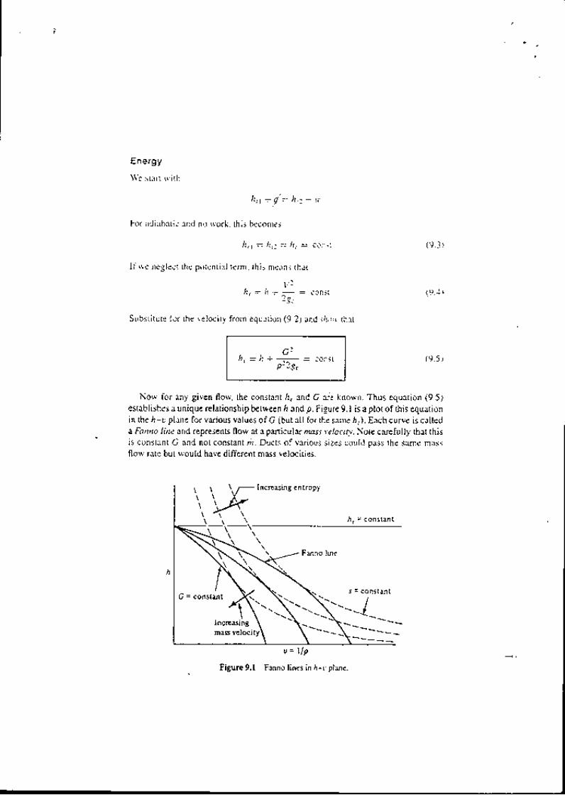
Energy
\\'e staft with
h,1 + y' = 7,' -' u
For adiabatic and no work, this becomes
h ' 1 = h , , = h r = c o n j t
If rve neglect lhe potential term, this means that
V 7/ 7 . = l t + 2 g c = c o n s t
Substitute for the velocity from equetion (9.2) and slror' rhat
/lr :, + --:- = constP- zEc
(9.3)
( 9 .4 )
(9.5)
Now for any given flow, the constant l, and G are known. Thus equation (9.5)esiablishes a unique relationship between ll and p. Fisure 9.1 is a plot of this equarionin the .4-u plane for various values of G (but all for the same ,r). Each curve is calleda Fanno line and rcpresents 8ow at a panicular mass vlociqt Note carefully that thisis constant G and not constant zi. Ducts of various sizes could pass the same massflow rate bu! would have different mass velocities-
u = U p
figure 9.1 Fanno lines in h-r'pla-ne.
mass velocity

Once the f lu ic l is knorvn' o"" t '1 : r l :o plot l ines of con\t i lnt el l t rop) L)n the /r- t '
c l iacrunt. Typicl l curres of ' ' ' ] ct t l l t t 'nt t re 'ht" ' n i is c l :Nhet l l ines in the l igure' I t
is nruch rrore instruct lve to p* i f t t t t Fa'rnc' l i t tes in the fanr i l iar / r --r p lene Suclr a
r l i tgratn i -s showl l in Figure ' ' t i t Ut ' t point ' a s ignihcet l t f ; rct beconles qui te c lear '
Since rve have rssttmetl th:rt there i' no heet trlrttster tr/'s.' - 0)' the orrir' * it)' th"lt
entropy can be generatet l ' t int" t*n i r ret 'ersi t ' i l i t ies ( ls i ) ' Thus t l tc ' f l t t t t ' t 'un otrh '
/)/{).grr.tJ tt)\t(tr(l ittL r((tsi'"3 t:t'i"tt' t't t'"tny;r'l \Vh'r ? ClrLn !otl locate the points oI
l t t ; i i ; . ' ; " t entropy fot eact i Fanno l ine in Figr-rre 9 ' l l
Let us esrnt ine o"t Et"no' i i 'n l i " -" t t t t i t t t t t i t ' F i-strre 9 ' i sho$'s a givetr Firnno
line togethenvith typical G;;; ii '*t' lrr point\ t)n this line represent-s-:::::^"]:ft
tlie silttte ntuss flo$' ,"t" p"""'ir lrel (tnass \eiocit)) 'lnd' tlte sirtrte stl-qnlttlon en-
thrlpy. Dtte to the irrevers iibt" '*tu"
ot the frictional ettects' rhe florv can onl) Pro-
.*.iio th. right' Thus the Fanntr line i: divided into t\r'o clistinct parLs' an upper and
n | : rver branch. rvhich are sepxrated L'r 'a l imit ing poir l t of t l lx i t r t t tn l entropy'
What cloes intuititln tell u-s ubour aiiabatic florf in a constallt-arel ducr'l \Ve nor-
n ta l t y fee l tha t f r i c t i ona le t l ec t s \ \ ' i l l sho l r ' t l pasa l l i n l e rn l l sene r r t i o t l o f "heaC 'w i tha correspondirrg recluctiott i'i""iti t' 'f the flLrict To prstihe snnte florv rate ($'ith
constantarea)'continuilv mt"lo't*t the Velo.'ily to increase'This tlt:::llll1"^tlt'
energy ruust caltse a decrease in enthalpv' since lhe.stagnation enthalpy remalns con-
stant. As can be seen i' Fi;;;;-i' tl"t agrees *'ith.fiow along the uppe'r hrunch of
the Fanno line. It is atso ctear inar in this c-ase both the static and stagnotion pressure
are decreasing' : * tr,r,o points on the lowerBtrt what about flow alPng the /t)r|er brunch'! Mtrl
branch ancl dra*'an "'oo i-' i'nAit"te proPer movement afonq^t!3-f1n1i":^,Yill
; ;;;;;;t d," tr.'. -' n tt'orpvi io the d ensitv l.�"-' ::l"l':J,[? :][ JilT# ffi:i.* !q*,i* (9.2)ll From the fisure' rvhat is happentng
slagnation pressure'l rirr l^ i'iit!' L ttith irrcrenstl' decrease'or rentalns constult'
f lgure 9J Two bmnctL5 of a FrnrKr line

Trble 9.1 -\| lJl] 5ii ( ' f Fr]lt lo Flort f irr Fiqure 9 -3
Ptrr l t ' I11 Up1'ur Br i rnc I Ll])$ cr B[trie h
tntl.r pvDcr is iL l\!'1,)cit)P lcr \ur , i {J t l l ! i ( }Plcsslt lc (r lu.t t t . t l i 'nr
Nor i :e th l r t t rn l t . r : l r ) rver b | l r rch. p lopenies iJo t t t : t I hr . r - in the ntanner predi t - ted
h. \ . i t t i l t ; t i i t ] . Th-r : rh is I lu \ l he a f l t t r i ' reg inte i | i th " r 'h ich wl r re r r ( r l ren f lnr i l i l r r '
Beibrc ,,r.e irrre.ti5.rte the Iirriitirr.l I 'oint that sePifiltei these t*'o flo'r'regiittes. let us
llote thet theie drri! i Co hll\e OIte thing io ct-rtttlttot. Recall the srxgnilhon presstlre
energv eqtlttion.
STAGI.IATION PRESSUFE-ENERGY EAUATIONccnsider the t$.o selrio.r locatiotrs on the plil-sical sYstetn sh'trvn in Figrrt e. .It_*i 1., ,r. disrence be t\'.ee1 thr.se :rrcatillni approa--h ze.'! ',. 11'c are dealing * itir an
ininitesimal c!rr)!ml !olult)e t i th the t lrenlrodi 'namLc states dif ierential ly separated'
as sho*,:r in Fi_rLrre brlon. Also sh,:ll 'n ate the corre;po[dil)g stagnalioll slittes ibr these
tn r locirions.\\ie rna-v .,rrite the follow.ing propert) ielation betrvien po'rnts I and 2:
Figure Inn nite rin:rl ly :e parited static slxte! \ l i lh associate'l s('1-cnatlon stntes-
T d s = t l h - v d p (.{ l)
T:
Note thar even tbouglt the strgnalioo states do not acttlnlly exist, they rePresent
legitimate themrody narniu- states, aDd rhrrs any valid property relation or equation
miy be applied to ihese points. Thus u'e mry also appLy equation (A'l) between
states l, and 2,:
II
II
t
,''
T, ds, : dh, - rt, dP, (A.2)

' l
Ho',r-c'r t'r.
i l l ) r l
r l s : t l q . * t / , c ,
| . \ .1)
(.{ - l )
r - \ . i )
r - { .6 l
r . \ .7 )
{ . \ . g)
: I lP,l andstagntrtiort P rts su rc.-t lE rg)'
I h i l \ \ t l t t i l ! \ \ l l l d
f i i ( / - s . + d5 ' j : d l t ' - t ' <1 l t ,
Rr'c;r l I th. ' .- l )r ' l - ;) ( 'qurt iol l l"r ir t .r t in th. ' Iorur
6 q : 3 n ' : * d l t r
B l subs t . i tu t ing . ' r l i r r [ ro r l r ! -q t t i r t ion ( -q .5 ) in to 1 ' { 6 ) ' *c t 'b t ' r in
,,\r7 : 'J11', * Ir(r/.r. * dstl + Lt d!"
NLr\r f,lslr r(-c ll thal
3 q = T d s ,
Stbs nue equotion (.4'-8) ilrto (A-7) and note tiat t1
you shor.rld obtain the tbllor';ing equation. called the
eqrtttion:
For Fanno flos'. d.r" : d u', : 0.
. Thus any fri ctional effect must cause a clecreltse in the total orstagnltion pressure!
Figrrre 9.3 r'enlies this lbr ffow alon,s both the upper and lorver t'r:lches of the
Fanno l ine.
Limit ing Point
From the enerty equation we had developed.
i!-! y als jTl - T ) + Tr dsi * ,5 u, = 0Pt
l ' / '
h , : h + ; - : c o n s t a n t
(.{.9)
(9.4)

Di f ' lerentiating, \\ 'e obtain
t ' d l /t l h ' = d i t + - = 0
3'
From cont inu i t r $e h i id tbund th r t
p l ' = Q : c 0 n 5 1 x n 1
i , J \ ' + V l t = 0
" d Dd t = - y -
p
Diiferenti i t ins this. ! \e Qbtain
q hich can be solred lbr
/ q - 7 1
/ O l \
(9.6)
(9.8 )
(9. i0)
( 9 . 1 1 )
r r Q l ? \
Introduce equatioo (9.8) into (9.6) and s/tor' thar
. . v2 dpdh = _______: (9.9)
8cp
Norv recall the property relation
which can be wntten as
T d s : d h - v d p
p
Substituting for dh from equation (9.9) yields
v1 dogcp
dp
p
We hasren to point our that this exPression is valid for afr,! f luid and belween
two differenfially sepa.ated points anyp[ace along the Fanno line- Norv let's apply
equation (9.11) to two adjacent poinls that sunound the Iimiting point of ma.rimum
entropy. At this location s = const; thus ds = 0, and (9.I I ) becomes
V2 dp--: = dp at lrrrut pornt
ot

(#)",,,,.,,,",", : '' (H), =.""' (9 . l i )v'r = g.
t__*
This should be a familiar expression [dp/dp= J ) &l ,]
and ue.recognize that fte
vetoci^. is soric at rtv l intit ing poini. i i{ upper branch t"" ":", ltJ*" :1.:: l i .!-
ff i ;;-";. t; i ,o"i ' u'o"i ' ' and the lower branch is seen to be the sttpersorttc
'-ull l " " begin to see a reason for rhe failure of our inruirion ro. predicr beha! ior
orr lhe lower branch of rhe Fanno ltne From our privous studies it sho\!s thll
f luid beharior in supersonic ttor" rr-ir.qu.nrty contrary to our e<pectations This
;;t;,r";;: ; i . i"., ,^tt"t *" l ive most of'our l ives "subsonicalLi""' and in facr' our
knovledge of f luid ptt"no*"n" tott ' *ainly from experiences with- inco mpress ible
fluids. It should be aPparenl that we ;;nnot use oLir intuit ion to guess at whrl miSht be
happening pafl icularly ln tne supersonic flow regime \\" must learn to 3et religious
and'put fairh in our crrcfully deri\ ed relrt ions'
Momentum
The foregoing aoalysis was maoe usiog only the conrinuitl',unO 1:t^:i'. l"t"ttont tnt
now proceed to appty torntntu* "o*ipi' o tht "ont'ol uolume sho*n in Figure 9 4
The ,t-comPonent or tne momenrum ei'u"tion for st"ady' one-dimensional flow is
l r , = i , . , r r � \- t v o u ' , - ' ' n ! . /
From Figure 9.4 we see that he force suflxratuon ls
f r , : t r A - P 2 A - F s
where F/ represents the total wall frictional force on the fluid between sections I and
z- Thus ihe momentum equation in the direction of flow becomes
Control voLume
(9. t 4)
v
tt !
r,A 4J--------vt fr"'t
Figure 9.4 Momentum analysis for Fanno ffow

t i oAV\ t ) - r : t f F t = ( l : l ' . t - - { l : 1 r )
g. -
.{ . -
s , r L r r ' t ha t cquJ t i on ' L L5 ) cJn bc r r r r t t en r s
r I P ' \ - - D L v ' -
o 3 . c t
/ r r v r \ F ; p : l , ll p + - | . = i : + -\ -!. ,/ ,.1 E.
( 9 . l 7 )
( 9 . 1 5 )
(9. r6)
(e.3)
( 9 . 1 8 )
In this fonn the equation is not panicularly useful except to bring out one signil icantfacl. For the steady, one-dirne siondl, constcnt-area fote of an'" fuid, lhe value ofp + pV1/g, can ot be constant if fr ictional forces are present. This fact wil l berecalled later in the chapter when Fanno flow is compared with normal shocks.
Before leaving this section on fluids in general, rve might say a ferv words aboutFanno florv at low ivlach numbers. A glance at Figure 9.3 shows that the upper branchis asymrotically approaching $e horizontal l ine of constant toral enthalpy. Thus theextreme left end of the Fanno line rvil l be nearly horizontal. This indicates that Eow atvery low Nlach numbers wil l have almost constant velocity- This checks our previouswork, which indicated that we could treat gases as incornpressible fluids if the lvlach--numbers * erc very small.
9 .4 WORKING EOUATIONS FOR PERFECTGASES
\\'e have discovered the general trend ofproperty variations that occur in Fanno flouboth in the subsonic and supersonic flow regime. Now we wish to develop somespecific working equations for the caseofa perfect gas. Recall that these are relationsbetweefl propeaties at arbitral ]. sections of a florv sy5lgrn wrinen in terms of N1achnumbers and the speci6c heal ratio.
Energy
\ l t start with the energy equation developed in Section 9-3 since his leads immedi-ately to a lemPerature ratio:
*
But for a p€rfect gcs, enthalpy is a function of temperature only. Therefore,
l t l = t t 2

No* for a perfect gas with constant specitic heats'
, - , ( r - r E p l ' \' r - . I I l/
Hence rhe energy equalion for-Eaano llo* can be wr !eqas
, v - l . \ I : ' - 1 . , ' \r , ( ' * ' . ' n ' , ' ) = r : ( r + / I " r r ' : ) ( e t e )
TzT1
l + [ ( r - l ) / 2 ] ' ! 1 , :l + t ( y - l ) / 2 1 : v .
(9.20)
Continui tY
From Section 9.3 we have
p V : C = c o n s t (9.2)
pg1 = p1V2 (9 21) : i
If we introduce the perfecl gas equation o[ state
p = p R T
the definit ion of NIach number
V : irlo
and sonic velocity for a perfect gas
^ _ ,Tn:Frr r - \ ' q _
equalion (9.21) can be solved for
pz ut ( Tr\t/t (g.zz)
a: M1\T)
Can vou obtain this expression? Now introduce the Emperature ntio from (9 20) and
ii'irin i"t. ,n. followlng working relation for static Pressure:

p . - l t l l l l ' 1 , - r l l l / , r 1 r ' :
p 1 -
r v z \ t + [ , . , - L t 2 ] u , ) /a a r l r
can eas i l y be ob tar : : : : r . rn t eqrLar ion (9 .20) , (9 .11) . and rheThe dens i t ; re la t ionperl 'ect gas la$':
l : _ Nlt
pr lvlz
t i 1
: - l r l l . ! / L( 9 . 1 1 )
Entropy Cha ng e
\\? start u ith an expression for entropy ci.r-.ji rhar is valid between any t'\ o poin ri:
a r 1 - , : c o r r i - n r n 41 . P l
( 1 . 5 i )
Equalion (4. l5) can be used to substitute rci c-. and rve nondimensionalize rhe equa-tion to
. t . - J l v T . D 1____: ln __: _ ln j_:
R y - l T 1 p l
If we now uti l ize the expressionsjust dereloped for rhe temperature ratio (9.20) andthe pressure ratio (9.23), the entropy chalr!r bicomes
s r - s r | =
y h ( l
- l t ' / - l ) / 2 ) M t ' � \
R y - t \ t - [ r _ t ) / 2 ) . v r ! )
(e.25)
, - M t l 1 - [ , v - l ) / 2 ] , 1 / r : \ | r- "'n \t-rt:lttr,'trl
Slolr,that rhis entropy change benveen tro lsints in Fanno flo* can be written a:
. ' 2 * s r , M 2 l I + [ \ / - l ) / 2 ] r v l r ? \ ( / + r r i ? ( r - r )
R M t \ l + [ , r ' - ] t / 2 1 ' v , : /(9.27)
Now recall that in Section 4.5 we integrdt.d d. stagnation pressure-€nergy equationfor adiabatic no-work flow of a perfect sa-i. \r ith the result
U = , -u aPrt

9.5 REFERENCE STATE AI ' ]O FANNO TA3LE
and equalion l9.lLrr btionl.s
r t .y:_!C_ = f \ , \ t .y) (e.:r l)T
- T - t ' r - l ) / l l t 1 r " '
\ \ ,e see rha t T iT ' - . i t . i l . y ) and \ \e can eas i l l cons t ruc t a lab le g iv ing \a lues o i
t/ i i u.rru, ,rt t ir : grrticular y. EclLt:tt ion (9 23 t can be lreated in a sirrl i lar fashion'
In th is case
p: =) p ,|1: = ,1 (an) vaLue)
t1 t : :? D ' . ! /1 .= : I
and equation (9.11 ; 'e.ooles
i , _ t ( 0 + t t l l . \ , , = t , . , 1 . r , ( 9 . 1 2 )
f -
J t \ l - l \ Y - t \ t l l \ l - /
The densitl r l i :o . ln be obtained as a iunction ol N1ach number and )/ f 'om
eqJon i9.:ir. Thi: is particularly useful since iI also represents a relocity r3tio
whv?
p \ ' . | ( r - ! ,_ t t , l !_ \ ' = r r , rz ,y t (9 .43)- : = - = - l -
F - r - , n \
t 7 + t ) 1 2 /
Apply thisame techriques !o equation (9 28) and s'toru thr't
f , . . . | \ / , r r I r : \ r Y - l ' / : t / - l l" , , = t ( t + l { y _ D / t t , v t - \ = 1 ru .y t e .44J
a - v \ ( Y + t t l 2 l
\\t nolv perform the same type of transformarion on equation (9 40)i that is' let
. r l + r M : + M ( a n y v a l u e )
' 11 $ 'Y ' � v l , :+ L
with the following r.sutt:
i ' r - r ' ) / Y l - l \ ' / l - l Y - l ) ' : l t l r \= | - I ln I ___--=:-:-- |
D , \ 2 Y / \ ( r + r ) / r /
- L ( L - r ) - / . - l t n M t ( e . 4 5 )l ' \ M = / z Y
But a glance at rhe Ph\ sical diagram in Figure 9 5 shows that (r. - r) wilt always be
a negalive quanriq: dlus lt rs more conve;ient to change all signs in equation (9 45)
and simplify it rc

ll
252 FANNo FLo$/
/ - _ ,I n r - I n ( t - '
a ' n , , ) = t n c n n s r
and then difterentiitring, we obtain
(9.3 2 )
dr , d ( t+ l {1 ' , t ) / 21 ,v2 )7 - t - t r . / - l t 2 l J l r
= " (9 .3 i )
wh ich car r be used to subs t i tu te fo rd l / f in (9 .30) .The continuity relation [equation (9.2)] put in terms o[ a perfect gcs becomes
4: .onr, {9.1: l )r/T
B) ' losar i thmic d i f fe ren t ia t ion ( take the nr ru r l l logar i thmon,J rhend i f te re t ra te ) . r l lo l rthat
dp d.\l L dT_ _ _ _ + _ o r g t 5 rp t v t 2 T
l\t can int{oduce equation (9.33) to eliminate d7/ f, wirh the resulr rhar
dp _ _d ,v _ | d ( t + [ (Y - D /2) tv2) .q ?6 \p t " I 2 l + l Q - t ) / 2 ) 1 2
which can be used to substitute for dp / p in (9.301.N'{ake the indicated substitutions for dp/ p and dT /T in fte momentum equcrion,
neglect the potential term, and srav that equarion (9.30) can be put into the followingform:
.dt d(l + lO - t) /2ltd1) div2 z dM' D, | + l t y - l )12 l , r l : l l J y i I I t
I d ( t + l \ y - t ) / : l , u : )\ 2 r ' l' y ' t 4 1 | - [ ( y - l ) / 2 ] , r / :
The last te|m can be simplified for integrarion b,v noring thar
r d(r + t (r - 1)/4M2) (y - t ) dtr2, , M 2/ M2 | + l (y - I ) /21M2 2y M2
(1, - r) d(t + tu - D/?ltvrz)(9.38)2y r+ l (y - r ) /7 ) tv2
The momentum equation can now be wriften as

tl.u l . + l d ( 1 + [ ( ] , - l ) i ' l i . t / r )
7y I + [ ( ] , - l i i l l . t l :
1 c l i l / + l d M ?- t M . - + t l =
(9. l9 )
(9 . .10 l
Equation (9.i9) is restricted to st.ad) one-dinlensionaL flowof a perfect-gas' with no
heat o. wark tr nsfsr. const3nt area. anrl neqii-sible potential changes' \\ 'e can now
integrate this eqtration bet\! een t\\ o points in the i l!]!\ and oblain
, f ( r : - r r ) y * 1 , -
D, ?i,
L ; l r r - 1 r , l l J / , :1 - - 1 1 7 - t r ' : l i v l ' l
| . . , - : - 1 i t l , :I I I r ' , ' ' j- t \ l t r
i t . : J 27 t v t , '
Note that in performing the inte-sration $e hare held the friction faclo( constalt
S o m e c o m m e n t s r v i l l b e m a d e o n t h i s i n a l r t e r s e c r i o n ' l f y o u h a v e f o r g o t r e n t h econcepr of eqLtivalenl diameter, .vou ml,v \! ant ro rer iew the last pan of Seclion 3 8
and equat ion (3 .61) .
9 .5 REFEFENCE STATE AND FANNOTABLE
The equations dereloped in Section 9.4 govide the means of computing the proper-
ties at one location in terms of tlose given lt some other locatio-n' The key to problem
solution is predicting the lvlach number af.lhe ne* location tkough the use of equa-
cion (9.40). The solution of this equation for 'he unlnown M: Presents a messy task'
u, no "^pii"i, relalion is possible. Thus we tum to a technique similar to thal used
with isentropic flow in ChaPter.We introduce anorher' tefetence state, *hich is defined in the same manner as
before (i.e., 'that thermodynamic state which \'rould exist if the fluid reached a Mach
numbeiofunity bl a partictiar procesr") l"rr thiscase we imagine that we continue
by Fanno fow ii.e.,more duct is added) unril the velocity reaches N{ach l Figure9'5
shows a physical system togelher with its f-s diagram for a subsonic Fanno flow'
1& 'ekr rowthat i fwecont inuea longtheFanno l ine( remember tha twea lwaysmoveto the righ0, we wil l eventually reach the l imitins point where sonic velocity exists'
The dasied lines show a hypothetical duct of sufiicient length to enable the flo!\' to
traverse the remaining portion of the uPPer brarch and reach the limit point Thisis
the ' reference pointfor Fannofow.
The isentrojic * reference points have also been included oII the I-s diagram to
emphasize the fact that the Finno * reference is a totatly different thermodynamic
state. One other fact should be mentioned. Ifdrere is any entroPy difference between
two points (such as points 1 and 2), their isentropic' reference conditions are not
the same and we havi always talien great care ro label them separately as l' and 2''

----'----_)- Acturlduit
- -1
III
I
l
,,1-'
t l 'tll t
Hypothetical du.t
I( r l
,rl I
Howerer. proceedjng from either point I or point 2 by Fanno fow will ultimatelvread to rhe ssme prace uhcn i\Iach I is reached. Thus we do no,i"".,o,"tt oi-i l--2' but merel.v ' in the case of Fanno flow. Incidenrally. *t y _. ull ,t rJ" " ..f"."n""points sho*n on the same horizontal l ine in Figure l.:: iVou ","y na"o to reviewSection 4.6.)lt'e. nolv rewriri the working equations in terms of the Fanno flow - r€lerencecondition- Consider firsr
T 2 + T
J
Figure 9.5 The' reference for Fanno frow.
T I + [ ( y - 1 ) / 2 ] & ! , 2: = - .t r l + t Q - D / z l V z l
L"., p:iA2 b€ an arbirrary point in the flow system and let its Fanno . condition bepoint l. Then
M2+ M (any value)
t u l t + l
(9.20)

and equltion (9.20) becomes
T ( y + I ) / 2
T - l + l l r - l ) / 2 ] / ! 1 1= f (N r , y ) (9.-l I l
We see thaf T lT' = f( l.y) and \\ 'e can easily construct a table gi\ ing laiues Qf
;i i : r;r;;t i ' l fo, o poni"ui", 7. Equation (9'23) can be treated in a simiLar lashion
In this case
p1 .-> p &1: '+ M (any value)
P t = + P " i / l + l
and equation (9.?l) becomes
L = ' ( ! , - ' , ' , / l ^ , , , , ) ' t = 7 , , " . r '
p . - , ! /
\ l + [ ( y - t \ / 2 ) . \ t : /(9.,l])
The density ratio can be obtained as a function of N{ach number and y from
.qu"tion {9.zil. This is panicularly useful since it also represents a velocitl ratio'
lVhv?
#=+: ie+;#Y)"' = ""'Apply the same techniques to equation (9 28) and slzarv that
# = * (+t#ffi (Y+r)r2o'-r) = r @'v)
(9.43)
(9.4.+)
\!'e now perform the same type of transformadon on equation (9 40); that is' lel
.r2 =+ r M2 =+ /v/ (anY value)
1 1 : i , r ' M t + l
with the following resuit:
(9.45)
ry:(+),^1::#fifv:)- iG- t ) - ' ; - ' , -M '
But a glance at the physical diagram in Figure 9 5 shows th,at (r' - x ) will always be
^ ""g;,i"" q*"ti,y; thus it is more convenient to change all signs in equation (9 45)
and simplify it to

/ r r ' - . { ) l v . t 1 , 1 l t y - t 1 / ) l \ t : \D , \ 2 v / " \ t r t r y _ t ) t l l , t r : J
(9 .15 i
The quan!it) (-! ' - .r) represents the amounr of duct that would hr\e to be addedto cause the flow to reach the Fanno * reference conclit ion. ft can alternlti lelr bevierved as the ma\imum duct length that may be added without chan-qinS some lit),.rcondition. Thus the expression
"f ft' - r) ir .",.d 4:\
D" D"
and is f isted jn rable along wirh the other Fanno fl ow parameters: T / T.. p,, p-.V / V' , and p, / p," . ln the next secrion w e shall see how this table -srearl\. simpliriesthe solution oI Fanno florv problcm\. But f irst, some uords about ih: deierminlrionof friction frcroo.
Dimensional analysis of the Ruid florv problem shows that the friction factor canbe expressed as
J : f (Re.€ /D) (9 .17)
where Re is the Reynolds number,
. R.=# ; (e.{s)
t t I \* t f , " ' - t ) = f \ l \ r ' Y )
and
tfD = relative roughness
Typicat values of e, the absolne roughness or average height of wall inegularities.are shown in Table 9.2.
The relationship among /, Re, and s/D is determined experimenr3lly and plouedon a chart similar ro Figure 9.6, rvhich ts called a fuIood.y diagramIf rhe flow rate is known together rvith the duct size and
Table 9.2 Absolute Roughness of Common r\Iaterials
Material € (ft)
Glass, brass, copper, IeadSteel, wrought ironCalvanized ironCast honRiveted steel
smooth < 0.0000 L0.000150.00050.000350.03

TLlrbulent f low regjr. le +
Log Re
Figure 9.6 ivloody diagram for friction f:rctor in circular ducls'
material, the Reynolds number and relative roughness can easily be calculated and
ih" uulu" of theiriction factor is raken from the diagram The cune in the laminar
flow region can be rePresented bY
64, - R e
For noncircular cross sections lhe eqlri valent diameter as described in Section 3 8
can be used.4 A
r
(9.49)
(3.61)
This equivalent diameter may b€ used in the determination of reladve roughness and
n"ynoiO, nr.U"r, und hence rhe friction factoc However' care must be taken !o work
*iii ,t " ot*f average velocity in all computations' Experience has shown lhat the
"ra oi un aq"i"^l"nc d'iameter works quite well in the turbulent zone',ln the laminar
i"*l"gl* ,f.rft *ncept is not sufficient and consideration must also be given to the
aspect ralio of the duct'In some problems the flow rate is not known and thus a rial-and-error solution
r"sults. As long as the duct size is given, the problem is not too diff icult; an excellent
^ppr*fi",i"*" the friclion factor can be made by taking the value conesponding
to wfrere ttre e/D curve begins to lelel ofl This converges rapidly to the final answer'
as most engineering problems are *elL into the turbulent range'
9.6 APPLICATIONS
The following steps are recommended to devetop good problem-solring technique:

i . Skercb rhe ph_vsical siruarion (including rhe hyporherical 'reference poinr),2. Label sectio ns w here conditions are kn.rLr n or desired_L L i .L a l l g i . cn in fo rmr t ion * i rh unr r . .
4. Compute the equivaient diameter. relxti!. roughness, and Reynolds number5. Find the fricrion facror from rhe l i lood., dLesram.
6. Determine the unkno$ n Mach numbe:.
7. Calculate the additional propenies d;sired.
The procedLrre above may have ro be alrercd depending on rvhat type of infonnation is given, and occasionaliy, trial-and-enor solu:ions are required. you should haveno diff icult,v incorporating these features on!-i rhe basic straightforward solurion hasbeen mastered. In complicated flow sy5gs6115 rhrr inr.olve more than just Fanno fforr,..a 7-s diagranr is frequent)y helpful in solr inu problems.
For the folloiving examples we are deaiing \,, irh the steady one-dimensional ffo*of air (y : 1,4). lvhich can be Eeated as a pedect gas, Assume that O = 14 = 0 andnegligible potentiaI changes. The cross-secrional area of the duct remains consranr.Figure E9. I is common to Examples 9.1 rhrough 9.3.
Figure E9.
Example 9,1 Giren M1 = l.80,pr =40psia-and.y: : 1.20. f indp2 and J Lx/ D.Since both Ilach numbers are known, we can solvi immediately for
p ) p ' . ^ | I \p: = - - pt = (0.80!r ( 93_ J
f. lOr = 67.9 p"ia
Check Figure E9.I ro see thar
f 3.r _ JL|M _ !L-_,.D D
- - - ' = 0 l J l g - 0 0 1 3 6 : 0 1 0 8
Example 9.2 Given tI: = 0.94, fl = 400 K. and l: : 350 K, find Mr and p./ pt.To detemjne conditions at section I in Figure 89.1, we must establish th9 ratio
I
/;\
I

r = \ r : - i + o o ) , 1 . s 1 e 5 ; - t t o ; :T ' T : T ' \ 1 5 0 /
1 l -|
- r'om Fanno lable at rV1 = 0 9-l
IL Given
Look up ? ' / f ' = t . i65 ' i in the Fanno !3ble add d! ' te 'minr thal ' '1 l : 0 ls i
I h u i
p : _ o : p ' = ( i o7 . r . r r ( . f ) - o l s rP P ' P t \ - : d u r o /
Notice that these examples confirrn pre! iaus slalemenls concernlog sli l t lc pressure
.fl""g".. f" subsonic flor" lhe static p;essure decreases' whereas in supersonic flow
ih. ri", i" p..rrur. increases Comprrre the stagnation pressure ratio and sholv that the
friction losses cause pr:/pr t lo decrease ln each case
For ExamPle 9 l:
(p1 l p,1 = 0.1 t6)
(,1i-
P t l
Example 9-3 Air f lows in a 6-in -diameter, insulated' galvanized iron duct- lni t ialcondit ions
*" oi : ZO psia, T1 = 70'F and V1 = 406 ft'/sec Afrer 70 ft' deermine the final Mach
number. temp€rlture and pressure
Since the duct is circulaJ we do noi have to compute an equivalent diameter' From Table
9.2 the absoluie roughness e is 0.0O05 Thus the telative roughness
e 0 0005D 0,5
\!'e compure the Reynolds number al section I (Figure E9 l) since this is lhe only location
\a here informJtion i l known
- . / ) O \ f l l j r
t . = # - - f f i = o r o r r b n v i c
/rr : 3.8 x t0-r ttf-secrti l l Air prop'rt ies table)
P t t
For Example 9.2:
Thuso , V ' D r
RF, : :-:---i- =
l t r8 ,
From the lvloody diagram ar Re =
determine that the friction factor is /need info.mation oo Mach numberg
( P ' : l P ' t = 0 6 1 l )
\ , ^ ' . \ t ' l J
t)l : '+ i
(0 . t02) ( {06) (0 .5 ) = 1 .69 x 106(1 .8 x l0 -7 ) (32 .2)
1.69 x 10⁶ and e/D = 00O1, we
tLn /yr , "
: 0.0198. To use the Fanno table (or equa[ons)' we
A - " ^,< . _ \ "5
..4t z ?.eX,'y'+ ^ ) 1 , " ]
,-/ "''
1 =z''4*2
-

at = Qg, .RTt ) t i . = t ( l . .1 ) (12 .2) (51 . t )153011r1r = t 123 gy , , " .
, v r r = \ = i ! 1 = n . , ^c r l l l S
- " - "
Fion the Fanno t ible at rt l t = 0.15,,re hnd,ra.
3= . r . 00 . ' ' : I = r . r os r 4=== r , r o ,P - 7 u
]1:_l?.j: ""T0j.,,:g the problem is in esrablishin-s the }lach numbef at rhe ourje(. riJ rhirrs oone through thefriction len2th:
/ A , r (0 .0193) (70)T
= -- ; -- =t t t '
Looking at rhe phl j icalskerch ir is appaienr (srnce I and D a.e constaors) rhat
f ! 1 _ / 1 i " , , _ r J . cD D
' - - = I l s O l - 1 7 7 1 = 0 1 0 3
\ ! 'e ente. the Fanno rable wilh thiJ fr ict ion tength and f ind rhit
Thus
ang
- T z T ' - / | \, . = VT, ' = ( r . t r36) { . .Gr / r r ro , = ,or"*
In the example above, the friction factor was assumed constant. In tact, rh.is as_sumptron was made when equation (9.39) was inregrated to oiojn (S.OO), ana *i,nthe introduction of the * referencein the Fanno,"ur.. r, tr,i,...","""';i:";i:i;i::1....rff11?"f,;11,;lil:li,"i],liReynolds numbers, which in tum drchange quite,^prdiy ;;;;;;;;;r:nil# ffJ'I.ll:,i;:i'li. nl::,:"J..*.rl:9.3-and compare ir wirh that ar the inf.t f y, = iie fJ*. l* u, joOZ
,r*. ,tBur don't despair. From conrinuiry we Low that *.;;J,;#;.is aJ*ays a
:"Tr-"::-11.:h^ the onty variable in Reynolds numbe r is ,fr" "i*rii,y E\rremelyrarge remperature variations are required,!o change the viscosity ofa gas irgnilicantly,and thus variations in the Reynoldi
1l::r"T"Thil;;;;;;#"ilil::ffi T*,T"ii'"i:T"T",H,T;hHwhere the friction factor is relatively inseositive to Reynolds numte.. .+ gleu,.a po-tential eror is involved in the estimation of the duci ;;G;;r;,;il nas a moresignificant effecr on the friction factor
H

Exatuple 9.1 A converging-diver-qing nozlh { i th rn alea 'at io o[ i 4] connects Io an u-l !-
long;onstanl-aiea rectangular duct (see Fi, :ui: E9'J) The duct is 8 x 4 io in cro\s sr 'ct irn
anihcs a ir ict ion factor of / = 0 01 \\ 'h:t i r lhe ninimum s(agnatioo pfessure feeding the
nozzle i t the f lorv is supersonic throughoul l ie enti i i duct and i ! exhausls ro l4-7 psia?
- ! r = 8 f t
- -+=* i i j r , " .= LaTpsiaI L I I
i /--'l---'-.- | .,=oo, It / - "
C 6 6 6Figure E9..1
4 A t : r - j : l= i . J J + l n ,
P 1 :( 0 . 0 : r S r r l l l- = u . J o
Tobe supefsonic with ArlA: =: 5.42' [ lt = 316' pil po = O'Olg5' hl P' = 0 1901' and
fLt^""/ D = 0.5582,
J r - 'n
7 , -1 , . . / ! r = 0 . j j3 t _ 0 .36 = 0 . l9S lD : --ry- o
€Thus
M r = t 6 1 3 a n d { = 0 5 1 + 3
a n o
t t , t l \o . , - t u t p t t p ) P D . = ( t ; { : - - L o . r g o
l - l ( t 1 . 7 ) = ? 2 S p s i . r, , ' -
p , t p , p . p , , - \ 0 . 0 1 3 5 / ' - -
\ 0 . 5 t 1 J . /
Any pressure above 288 psia will mainnir the ffo$ system as specified but wilh expansion
waves outside the duct. (Recall an undere\Pn-aded 0ozzle ) Can you envision what would
happen if f ie inlet stagnltion pressur. fell belou 133 psia? (Recall the operation of ao over-
erpanded nozzle.)
9.7 COFFTELATION WITH SHOCKS
As you have progressed through this chapter you may have noticed some similarities
b" t*eenra, rno- f lowandnormalShocks.Lelussummar izesomepeninent in |or .malion,
D

The points just bei.-rre and after a normal shock represent states q ith the same massllow per unir area. rhe same ll lue of p + p vrg". i l ;; ,;; ,*_"n",ion .n,t utpy.These facis are the resutr of appl.vin-q rire b"ri" ;"*;;;;;;;"i i"",r,-.".n..,"., *oener-qy to any arbirren Iiuid. This anal_vsis resulted in equarions fO.Zj, i i .:1, ana fg.Sl.A Fanno line represenrj states with the same mass n;!v per u;i;;J; anq rne samestagnation enrhalp_v. This is conErmed bI equations <s.) ;"di;.;;.;. moye atonoa Fanno line requires fricrion. At tbp"-*J ;;;;;; ; ; il .'* ?;ffi : ",j;f ""."',,,":,r;iJ::ilt:ry"f :'llr::i;
Tie variarion of rhe quanritv o +,pV2/g."along a Fanno line is quite interesting.Such a plot iy shoq n in i,gu,e'e. z. you *i i i no,o"'t iut f* ";;;;"1;; ;" the super-sonic branch gi the Fanno line there s a coc.espondin-q point on the subsonic branchL':,lJl::T" l"',. or p + p v!/ se .-thu, trl*" t*"-pj"',, ,"i,"rf "u ,r,r?. "o"0,,,o",ror the end points of s normal shock and could be coonected Uyir"i " ,n*f. Now we can imaeine a supersonic Fanno flow leading inl i no.mal snocf f f rf,isis followed by additional duct, subsonic Fanno flow,,vould occur. Such a sltuation issholvn in Figure 9.So. Note that rhe shock merely causes tle noru.tluirp from ttresupersonic branch to rhe subsonic branch of the so.,a" nr""" f rn". fi"Jiigure 9.gb.l
P + ; i - : g .
> 1
Fisure 9.7 \ 'ar ixr ion ot p L pV: ig, in Fanno l lor,, .
Figure 9,8a Coobinarion of Fannq flow and normal shock (physical sysrem).
-11> IFarno flow
, ' / < lFanno flow

Sl:ock - )
\'
/
I
Figure 9.8, Combinrt ion oi Fanno f low and.no.mal shock.
Example 9.5 A large chambef contains air ar a tempefature of 100 K and r p.essure of gbar abs (Figure E9.5). The air enrers a con!erging-diverging nozzle \r. i rh an area rat io of 2.4.A constant,area duct is attached to the nozzle and a normal shock st lnds ai the exi! plane.Receiver prcssure is 3 bar abs. Assume the entire syJtem to be adiabatic and neglect ir ict ion inIhe nozzle. Compute the / A.(/D for the oucr.
Figure E9.5

Fof a shock !D occu. aj speci l ied, the duc! f lo!! rnust be supersonic. Nhich mians rhrrthe nozzle is opcrating ar i l i rhird crir icul point The inler condi( ionr and nozzle areu r lr i i rf ix condit ions ar locrr ion J. \ \ t can then f ind p. at rhe t ip of the Fanno l ine_
. lhen rhe . ir i ic
pj lp' cnn be computed and rhe i \ ' {ach numbe. afrer lhe shock is found from tha Fanno txbla.This solut ion probabll .would not ha\.e occured to uj had we not dia*.n the I_s uragram anoreco-gnized that point 5 is on the ssme Funno l ine as J.4. and'_
For Al/At - 1..1, , l1r = I. l and pj, /p,r = 0.063-10. \ \ t proceed immediarelr to conrlure
i : = + r+4 -4 = f : ) , , f _ : , ) ( o l r L r = r ?o j op ' p . p : \ p i p ' \ s . / \ u . r b i l /
From the F:rnno trbl. \re nnd ther rt l r - 0 619. anLl rher from the shcck t3ble..f1r = l . lS9Retuming to the Fanno lable, /Lra,!, /D = 0.-1099 anC /Zr,r*/D = 0.2_tSl. Thuj
= 0 . 1 0 9 9 - 0 l i s t = 0 . 1 ; lD D
9.8 FRICTION CHOKING
In Chapter 5 rve discussed the operation of nozzles that were fed by consranr sragna-tion inlet canditions (see Figures 5.6 and 5.8). \Ve found that as the receivcr pressurewas lowered, the flow through the nozzie increased. When the operating pressLtrercrio reached a certain yaLue, the section of minimum area developed a ivlach numberof unity. The nozzle was then said to be choked. Further reduction in the pressureratio did not increase the flow fate. This was an example of area choking.
t
Tlpr
l/)
Figure 9.9 Co{erginB nozzle and consrlnt-arca duct combinarion.

4 = constant
s
Figure 9.10 T-s diagram for nozzle-doc! combinal ion
The subsqnic Fanno flow situation is quite similar' Figure 9'9 shows a given length
of duct fed by a large tank and converging nozzle lf the receiver pressure is belo$
the tank pressure, flow rvill occur, producing a ?-s diagram shown as path l-2-3 in
fig"." 9iO. W*. Oat we have isentropic Row at $e entrance !othe duct and $eo \re
mive along a Fanno line. As the receiver pressure is lowered still more' tie flow rate
and exii lvl-ach number continue to increase while the system moves to Faffro lines of
higher mass velocities (shown as path 1-2'-3')' It is imponant to rccognize $at the
receiver pressure (or more Properly, the operaring pressure ralio) is controlling the
no* rnis is because in subionic floru the iressure at the ducr exit must equal that of
the receiver.Eventually, when a certain pressure ratio is reached' the Mach numbe' at the duct
exit will be unity (shown as path l-2"-3") This is called/naion choking aj.d af.y
funher reduction in receiver pressure would not affect the flow conditions inside the
at.i"^. *tr" *""rd occur as the ffow lear es the ducr and enters a region oi reduced
pressure?Letuscons ider lh is las tcaseo|chokedf lowwi th rheex i !p ressureequa l to the
,a".it"t ptatt"r". N ow suppose that the receiver pressure is maintoined at this vslue
but more duct is added to the system (l"lothing cin physically prevent us from doing
,ttrir.) W't u,t happens? We know that we cannot move aro''nd the Fanno line' yet
,o rn . t 'o *wemust re f lec t theaddedf r i c t ion losses .Th is isdonebymov ing toanewFannolineatar/ecreosedflowrate.TheT-sdiagramforthisisshownaspathl-2,',-3"'- + in Figure 9.1 l. Note that pressure equilibrium is srill mainlained at the exit bul

t
Original duct chok3d.,l/l = I
Supply air
III
, I .r 4 t
p,e- held constent
, u = 0
Fanno line fo.o. iginal duct - - iV = |
G , , , < G "
Figure 9.11 Addition ofmore duct when choked.
the sysrem is no longer choked, although the florv l3te has Cecreased. Whet rvouldoccur if the receiver pressure were norv lowered?
In summary, when a sulsoaic Fanno flo* has become/n-clioa choked. and moreduct is added ro rhe system. fre florv raie musr decrease. Just ho',v much it decreasesand whether or not the exit velocity remai ns sonic depends on how much duct is addedand the receiver pressure imposed on the system.
Now suppose rhat we are dealing with supersonic Fanno flow that is fictionchoked,ln this case the addition of more duct causes a normal shock to form insidethe duct. The resulting subsonic flow can accomrnodate the increased duct length atthe same flow rate. For example, Figure 9.12 shows a Mach 2.18 flow that has anJL^ / D value of 0.356. If a normal shock were ro occur ar lhis point, the Machnumber after the shock would be-*iout 0.550, which cocresponds to an /|.*/D
I l = constlr l
Pt = constant
l't - o
l ie w Fanno l ine at-- '- t-
lo,* e r f low rarc_\*1,-

l - t+=o i i6 - -
,V = 1 .0
N3r:nr lshock
L _ . ,. , - ; : = o r r 8
value of0-728. Thus, in this case, the appearance of the shock permils over twice the
duct length to the choke poinl. This difference becomes even greater as higher NIach
numbers are reached.The shock location is determined by lhe amount of duct added As more duct is
added, the shock moves upstream and occurs at a higher Mach number Eventually'
the shock will move inlo that portion of the system thal precedes the constant-area
ducr. (lvlost likely, a converging-diverging nozzle was used to Produce the supersonic
flow.)lf sufficient friction length is added, the entire system will become subsonic and
then the flow late will decrease. Whether or not ihe exit velocity remains sonic wili
again depend on the receiver pressure.
9.9. WHEN y lS NOT EOUAL TO 1.4
As hdicared earlier, the Fanno flow table is for 7 : i 4 The behavior
of /L.al/D, the friction function' is given in Figure 9.13 for 7 = 1 13, l 4 and 1 67
forltfach numbers uPto M :5. Here we can see that the dependence on / ls rather
nodceable for rll : 1 4. Thus, below this Mach number the tabulation in fanno labl€
mal be used with Iittle error for any 7. This means that for subsonic flows' where most
Farno flow problems occur, there is little difference berween the various gases' The
desired accuracy of results will govern how far you want to carry this aPproximation
into the supersonic region
Suictly speaking, these curves are only represenlalive for cases where / vanatrons
Ne negligiite witiin the fow. However, they offer hinls as to what 44gnitude of
Figure 9.12 [nf luence oi shocl on r:1.] \ imum duct length

Uore duct added
_l_\I l = constanl
= cOnstant
Figure 9,11 Addit ion of more ducr when choked.
the system is no longer choked. although the flow rate has decreased. What w,ouldoccur if the receiver pressure pere now lowered?
In summaw, when a sabsanic Fanno flow has become/noioa cloted and moreduct is added to the syslem, the ffow rate must decrease. Just how, much tt clecreasesand wheth€r or not the exit velocity remains sonic depends on how much duct is addedand the receiver pressure imposed on the system.
Now suppose that we are dealing with supersonic Fanno flow that is fictionchoked.In this case rhe addition of more duct causes a normal shock to form insidethe duct. The resulting subsonic flow can accommodate the increased duct lensth atthe same flow rate. For example, Figure 9.lZ shows a Mach 2.lg flow that hL anfL,n",/D value of 0.356. If a normal shock were to occur at this point, the lvlachnumber after the shock would be abott 0.550, which conesponds to an fLftax/ D
Fanno line fo.original ducr
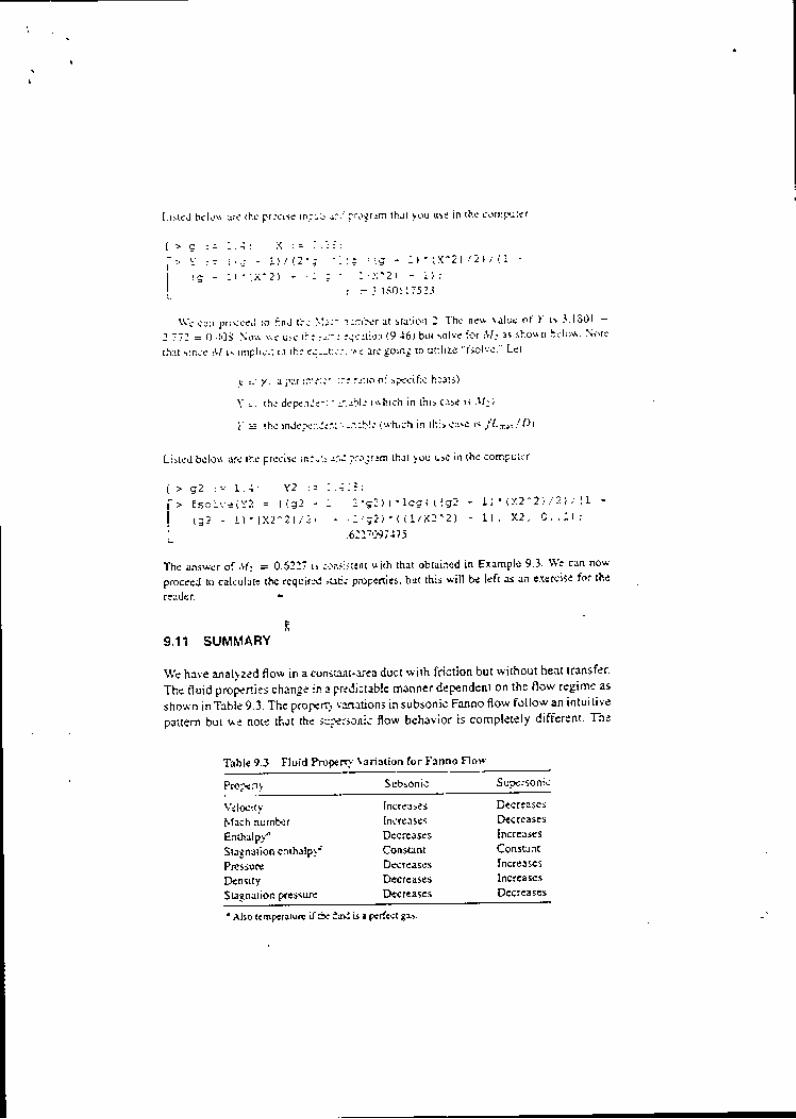
Listad belo\\ i rre the p.ecise in:L'- i ; : : ?.ogrrm rhal yotl t lse in lhe compuler
t > q : = - . . . : I : = - i : :
[ ' Y : = { ; r - \ J / 1 2 ' ; - - : - ; r i E - : } - \ \ ' 2 ) / 2 J / t l
| ' e - : , ' x - 2 ) - : ; ' : : ( ' 2 ) - l ) r
L ! = j r s D r r T i : . l
\ \e cun pro;c-ed lo f ind lh. \ : :- ' i ) ienber at stal ion 2. The new value of y is 3 1801 -
2.772 = 0.103. \o!v \r 'e use th. !- : : .qul( ion (9 46) but solve fo. Ml as sho*f l below' Note
(hrt since r!1 is i pl ici l in lh. ei: : l i : . \ : ar. going to ul i l ize -fsolve ' Let
-g = /. a parlr i is: L_.t r : t io of specif ic heats)
.X = the depe;1J.l i 1i l :r ' r l . ($'hich in thi i case is rt l l )
l = lhe ind.ler ' l . l :1: ixble ( lvhich in thiscase is /L."*/D)
Listed belorv are the precise inlr-s r: ,J irogram that you use in lhe compuler '
1 ) i ( x 2 ^ 2 ) / 2 t / 1 7 +
I L X 2 , A . . I ) i
The answer of Lll = 0.6?21 is .!1nsis!ent with thsl obtained ir Example 9 3 \\'e can now
proceed to calculate lhe requit.d irfi; ProPenies' but this will be left as an exercise for the
l > 9 2 : = I . 4 : Y 2 : = l . i l !
f > f s c l v e ( Y 2 = l ( q 2 - ' - ' . 2 ' s 2 ) l ' 1 o g ( ( ( q 2 +
I , n t - r \ " l r i 2 ^ 2 J / 2 t : - . ' - / q 2 ) ' � ( ( L / X 2 ^ 2 ) '
L cta97415
T
reader
9.11 SUMMARY
We have analyzed flow in a consr:.nr-area duct with friction but without heat transfer'
The fluid properties change in a predictable manner dependent on the flow regime as
sho*'n in Table 9.3. The ProPerr,! Eriations in subsonic Fanno flow follow an intuitive
pattern but r.r'e nore that the super:onic florv behavior is iomplerely different' The
Table 9.3 Ftuid Propen}- l-ariltion for Fanno Flow
Prope nt- Subsonic Supersonic
!tloLityNlach numberEntialpfSi!gnation enftalp)'Pre5suaeDensityStagnation pressure
IncreaseslncreasesDecreasesConstantDecreas€sDecreasesDecteases
DecreasesDecaeasesIncleasesConstantIncreasesIncreasesDecreases
' Also temperaN.! ifl: i'rid iJ a p.rfec! 8as.

onll contnton occurrence is the decrease in stagnilt ion pressure, which is indicativeo f the ioss .
Perhaps rhe nlojt si,gnificant equations are those thar applr ro all f luids:
h ,
p l ' : C = c o n s t a r t
= o * # i : c o n s L a n L
(9.2)
(9.5 )
Alon-s !,, irh rltese equations you should keep in mind the appearance oI Fanno lines inthe l;-r and f,-r diagrams (see Figures 9.I and 9.2). Remember that each Fanno Iinerep.esentj gfinrs r.irh the same mass velociry (6) and sra-snarjon enrhalpy (h.), ancta no.m3l shock can connect t lvo points on opposite branches ofa Fanno line $hichhare d13 5xfl16 value oi p + pV. /g". Fanil les ofFanno lines could represenr:
Diderenr velues of G for the samell, (such as rhose in Figure 9.10), orThe sanre G for different values of h, (see problem 10. I 7).
L
Deteiled rr orking equations *,ere developed for perfect gases, and the introductionof a - reference poinr enabled the constcuction ol a Fanno table which simplif iesproblem solution. The * condicion for Fanno flow has no relation to the one usedpreviousl,v in isenrropic flow (except in general definii ion). All Fanno flows Droceedtoward a l imiring point of lv{ach l. Friction choking of a flow passage is poisible in
fanno flow just as area choUng occurs in Iarying-area isentropic flow. An ft_s (orT-s) diagram is of grear help in the analysis of a complicated fl-orv system. Cer rn rorle habir of drawing rhese diagrams.
PROBLEMS
In !h9 problems thar fol low you may assume that al l systems are completely adiabatic. AIso, al lducE a.9 of constant area unless other*ise indicated. you may neglect friction in the va.?ing-area sections. You may also assume that the f.ictibn factor shor,,.n in chans appliesto noncircul3i cross sections when the equivalent dianeter concept is used and the f lo* isturbl]lenr.
f 9.ycondit ions at the entrance to a duct are l t l1 = 3.g un6 pt = 8 x l0r N/m:. Af!e. a' .J cenain lengrh the ffow has.eached M: = 1.5. Determine p: and f A.r/ D i f y :1.4.
{9.?7lA-flo" of nitrogen is discharged from a duc wirh t1: = 0.85-, I: = 500"R, and p: =
\J ?3 psia. The rempe.arure at the inlet is S6O"R_ Com-pm€ th-ipressure ar rhe inlet andthe-rnass velociry (G)
93. Air enrers a circular duct with a Mach number of 3.0_ The friction factor is 0.01.(a) How long a duct (measured in diameters) is required to reduce the Mach numbe,
to 2.0?

L--
- . : 1 , . , _ a , , ' ( ' , ' " t
) ; :, >'aL>
/ : 1
' )\ i -- - \ - t
7v\ l-"-e-
- i . ' ,
I r r
lb) what is the percentlge chanse in temperature, pressure and den i(t ' \ , C l , ' r , i \ I I f ,
(c) Dete.mine the enl.opy inc€ase of lhe air
(d) Assume the same length of duct as computed in pan (a). but the rrrt i : l \ l lch
number is 0.5. Compute the percentage change in remperatufe. pre!!ui: denti t) '
and the enlropy increase forthis case Compare the changes in the rxme length duct
for subsonic and supersonic l low' !
9.4, Oxygeo eniers a 6-in.-diameter duct wi lh n. = 600"R' Pr = 50 psir. rnJ l i = 600 , , /ftlsec. The tiiction facto. is / = 0.02.
(a) What is the maximum length of duct pen-oi l led thxt \ ! i l l not chan!:e 3n! ol the
condit ions at the inlet?
-^. (b) Deiermine 7r, p2. and V2 for the merim um duc( length found in piril I I I
, / 9.s.) l ;r Ro*s in an 8-cm-inside diameter pipe that is 4 m lo0g. The ai. enteis * i th a }Isch
t-,-/ number of 0.45 and a temperature of 300 K
(-_ 9.6.
(a) What friction factot lvould cause sonic velocity a! lhe exit?
(b) If the pipe is made of cast iron, estimate the inlel pressu.e
At one section in a constant-area duc! lhe stagnation pressu.e is 66 8 pjia l]I1d the }lach
number is 0.80. At another section the pressure is 60 psia and the lemper:ture is l]0"F'
(a) Compute the temperature at the first seclion and the Mach numbcr 3( lhe second
section if the ffuid is air.
{b) which way is the air flowing?
(c) What is the friction length (/ A.r/D) of the duct?
= 3.0 and lea\es at Ml =
{a) Find the static and stagnation conditions at the enttance.
tb) whar is the friction ficto( of fte ducl? t
9.8. A duct of 2 fr x I ft cross section is made of riveted steel and is 500 ft long Air enters
with a velocity of 174 ftlsec, p| = 50 psia, and Ir = 100'F.
(a) Determine the temperature, Pressure, and velociry at |he exit.
(b) Compute the pressure drop assuming the flow to be incompressible. L;s' rhe en-
tering conditions and equation (3.29). Note that equation (3.61) cafl r3sily be inte-gru(ed to evaluirte
| - ' . a r V l
J ' ' " ' - " o , z c "
(c) How do the results of pans (a) and (b) compare? Did you expec! dis:
9.9. Air entecs a duct with a mass flow rate of35 lbrn/sec at Tr : 520'R and pr : 20 psia'
The duct is square and has an area of0 6t fi:. The outlet l{ach Nmber is uniry'
(a) Compure the temPe.ature alld pressu.e at the oul]et.
(b) Flnd the length of the duct if it is made of steel.
9.10. Coosider rhe flow of a pedect gas along a Fanno line. Show th.t the pressure a! lhe '
reference state is Siven by the relatioo

a
r - : ' ' | : n r ' ' ' :A L v - ? , i ) , - l ; j
9 , 11 , A l 0 f r duc r l l i n . i n d i amerNleasurenrcnrs ar rhe inlet nir: t
tont" i l l t o\ l : i 'n dolr ing ai lhe rate of s0 lbm/sec.
*u", i , 'o, ="tr 'or*.rr ' I l r erte pl = J0 Pri l an' l r l = 800'R The pressure al the
(a) Calcularr , l / l , tVy 12. Ta, and pa.(b) Determlne rhe f.iction frct
ref lal. or ano estrn:re th: ab\olute roughness of the duct m4_
49.12. / ! rhe outle( of a 2 j_cm-diamerer ducL air i j t_r! i l ing 3t sonic velocitv $. irh a rempef_\ -_,/ , / a.ufe of l6.C and a p.essurc of lba... f let. .r i : .en--sm-o-o,n*ir, i i ," ,"^r.rn*"
irre ! lvo pojsible condit ionS Ihat(a) Find rhe sraric and,,"*"",,"ffi.'.i.1,i'J, ;::il:J;l!1"llio"n"".ono,uon.(b) Assuming rhe sunounding air ro b" "r.t .,,", pr.srur", tr_.u.i i*."oorr., , l lnecessar).to get ambient a
losses in the work proiarr-r" tnto lh' duc{ for eaih case? (You may assume no
tt. lilf iffi..:,:111",:.1],1;] o,i" *.",:r!tri.ijenlropicariy into a r2-jn.-diamererduct.r) 0.50. \eglecr 3ll fricrionsl efiicrs ercept r" ,:Jffi,*idi;
Afrer^l0O fr rhe ducr rransirions jnro rn g x 6 inI t U . )U. - \eq lecr . l J f r i . . i ^ " " ' -F , -^ , . - . - -
!rhefe the i \ lach nurnbea
(a) Detcnri i i re the Mach number ar the duc! .n";; ' - , r : 0 .0+ .
(b) lvhat are the temperatu.e and p.essure in de sqrjare sec|ion?k) How much 8 x g in. square duct could be added be fore the tjow chokest 1,l,ssumethat / = 0.04 in this ducr also.) .
Ix,;n;:i,r; ;"1: ll,)1".:.1{1.=^ry K eoreN a fricionress convergrng_divergino n6721q having an area rat ios!.e,s,xg ruzre navlng an aJea ratio of 1.0. The nozzle discharges srrpenoni..uuylnto a constanl-area ducr that has a fdcttDn lenerh /. \r /n _lemperatuae and pressure at the exit of the ducl
len_sth / A.(/O = 0.35S. Derermine ti l
?lilf:*t::"-::"X:focj are '{, = : 5. p,, = 67 psia, and 4r = 7006R. rhrsi s f o l l owedbya reng tho fFanno f fowa , rd P 'o ' c r ru r r r= /uu 'K - l h i s
The are;r chrno" i . " , , .r c:nreryrng nozzle as shown in Figu.e p9.15.
I-1.;T;:.n*t" ,, such rhar rhe s)5rem i' .;;r.Jli""r,;ilil:"",iljiJjtl'#;']
1.1.7 psia.
l . r .7 pr ia
6 6""-,tlr - 2.5
Irr = 700'R
* Figure p9.15

l ' ' . '
. -(a) Dra\\ a f-J diagrlm fo. the system
(b) Fiod .!1r xnd,l1r.
(c) \\'hr! ij .l f.I i D ib. the duc(?
Tti i) A .ont"rging-i l i \erging nozzle (Figure P9 l6) has an area rat io of 3 0 The stagnationL---- l concl i t ions oi lhe inlei air tu-e !50 pl ia and 550"R A conslani-aiea ducl wi lh a lcnglh
of l2 di3iretefs is al lached to lhe nozzle outlct. The tr icl ion factor in the duct is 0 02-5'
, l9. l conrPu(e the r:Jel!er pre\ 'ur. lhl t ! !oLr[ l plr--c r shocL
( --- rir in rh. nozzre thro ,. & -_ !] " >
, , t ' , r r t he n ! ' z z l e e \ t r ;
( i i i ) al rhe ducl e\! t .
I
C_)(b) \ \ 'hr! raiei!cr pressu.e would cause supersonic f lo* throLlghout the duc! with no
sho.ks * irhin the syrtem (or aftef the du.t exit)?
(c) i \ lake r s\etch similar to Figure 6.3 show ing the pressure dislr ibul ion fof the vanous
operrt in-r poinrj oj 'pirns lo) an,i (b).
)2 . !
.7Yrl
- IQc/1 urp
(
)
I
tP
1t,.'1 -; c--
. t';
\, ,"; f '^"(: : ' ' i,. , i , i . . . t
\O\'
" p, = r:o e,i"
/-. 7, = sffE
(a) Sketch a I-s diagram for the system.(b) Determine the fliction factor of the duct.-(c) What is the toral change in entropy fo. ihe system?
I large chamixr contains air at 65 bar pressure and 400 K. The air passes through a
con"eiging'only nozzle and theri irito a constaiit-area duct. The friction lengft of the
ducr is / .(/D = 1.067 and the lvlach number at the duct €xit is 0,6'
(a) Dra* a I-s diagram iot the system.
(b) Detemine condit ions at the duc! enfance.
(c) What is tie pressuie in the receiver? (,ryintr How is lhis related to the duct exrt
-: PressuEl)-rf@tt, ,tt" t.ns.h of the duc( is doubled and the chamber and receiver co'tditions remain
'9 un.h-n"--d. *hat are tire new Macb numbeir ai the enttance ana exit of the-duct?
, _:- .( 9,19. \rq, "onttant-arca duct is fed by a convergidg-only nozzle as shown in Figure P9' 19' The"'--*---lnozzle
receives oxygen from a laryejlS!99r-4J PL = 100 psia and G = 1000"R' The
duct has a friction length of 53 anit it is choked ar the eK;t' The receiver pressure ls
-. exactly the same as the Pressure at the duct exit.
O - t
-( at <'
p g .
t L ' I l L,/: ' '
/ ;( A (. Figure P9.16I l -
(j.n)io, u nozzle-duct system similar lo that of Problem 9 16, the nozzle is designed to
^ l- ,---1 Dtoduce a l l lach numberolzJ with i ' =l.4 The inletcondirions are pr| = t0barand
'e ( ?".r = 370 K The dr-rct is d diahretec in length, but the duct friction factor is unkno'''n'
$ it. ,"".i';;;;.;;" is fixed at 3 bcurqd a-normal shock has formed at ttrelill eiii

Y '
qa7\ -
\\-
I
Pt = 100 pr i t rf . = loo0"R
I
It ^ .
i
( r )M { z y
M't. ') L--Figure P9.19
(a) $ hat is th.- pressu.e a! the end of lhe ductl
(b) Four-f i f iht of the ducr is removed. (The end of rhe duct is norv at 3.) The chamberp.essure, receiver paessure. and ir ict ion factor renrin unchanged. Nolv * hat is thepr:ssure ar the exit of the ducr?
(c) Sketch both of the cases abole on the sitme I-J diagram.
9.20. (a) Plor a Fanno l ine to scale in the ?-s plane for air enrering a duct with a Nlachnumber of 0-20, a stat ic pressure of 100 psir, and o stat ic rempe.ature of 5-+0.R.Indicate the Nlach number at vaaious points along lhe cua1e.
(b) On rhe same diagram, plo( another Fanno lioe for a flow with the same totalentltalpy, the same entering entropy, but double rhe mass velocity.
9.21. \rhich, i f any, ol the rarios rabulaled in rhe Fanno rabte (I / I . , p/p., pt/p:. .rc.)could also be listed in the lsentropic table lvith the same numedcal values?
9.22. A contrdctor is to coonect an air supply fao.n a comp.essor to test apparatus 2l ft away.The exir diam€te. of the compresso. is 2 in. and the entrance to the test equipmenthas a l-in--diameter pipe. The contracto. has the choice of putting a reducer a! thecompressor followed by l-in. tubing orusing 2-in. tubing and putting the reducer at rheeotl-ince to the test equipment. Since smaller tubing is cheaper and less obtrusive, theconrractor is leaning toward the 6rst possib ility, butjusr tobe sure, he sends the problemrc rhe eogineering personnel. The air coming out of Ihe compressor is at 520"R and rheprcssure is 40 psia. The flow rate is 0.7 lbnL/sec. Consider that each size oftubing has aneffective / = 0.02- \rtat would be the condilions a! the entrance to the test equipmentfor each tubing size? (You may assume isentropic ffo*. everywhere but in the 2l fr oftubing.)
9.2,3. (Optlonat) (a) Ioroduce the' reference condit ion into equation {9.27) and develop anexpfeision fo. (. t ' - J), / R.
(b) Wrile a computer program for the expression develop€d in part (a) and compure atabie of (J' - s)/R versus Nlach number. Also include other eotries of the Fannotat'le.
CHECK TEST
You should be able ro complete-4 s tesr without reference to mate.ial in the chapte.
L

l ' ' l
9.1. Sketch a Fanno t ine in the i-L planc. lnclude enough addit iontl infocm:t ion as necessary
to locate the sonic poini and then identiry' the regions of subsonic anJ iuPersonic f lo\! '
9.2. Fit l in theblanks inTableCTg 2 toindicate whethe. the quanti l ics i : ' r ' : ;se decrease o(
re |{rin consta itr lb,e case of Fanno flow
Table CT9.2 Analysis oi Fanno Florv
P.operI) Subsonic Regime Supeii . .r l . Reginie
\tlocity
PressureThrust lunction
( p + p v 2 / g , . )
9.J, in the system shorvn in Figure CT9 I ' the fr ict ion len-qth of lhedui{r ' r \r , /D-= 1110
and lhe luach number at the exit is o S Aj = l 5 inl rnd A1 = I0 in: \ \ t3t is the air
pr.ssure in the tank i f the receive. is al l5 psia?
9.4, Over what range of receiver pressures will normal shocks occu' someplace within the
syst.m sho*'n in Figr.rre CT9.4? The atea ralio of the oozzle is "{3,r'{; = 1'l0l.tnd6e
d u c t f A r , / D = 0 . 3 0 .
= 15 psia
/u, ( 'z , ,8
l " \ . .kt ' . (" '
" 1 \
L-ergecha.rnb€ r
Pr = 100 PsiaTr = 600'R
Frict ion
6Figurec"tg.1

( f
i , '
9.5. There is no fr ict ion in the systeri sho!!n in Fi juai CT9.5 except in the constant area ductsfrom I to l and t iom 6 to 7. Skerch the f- i Jrrsarm for the entire svstem.
lrrg:
I
,\t l )
A( 6 )
i i -ioo
I
{ 7 )
I
t l )
Figure CT9.5
9.6. Star1ing \! i th the basic pnnciples ofconti iru:tr. energt. and so on, de.ive an expre| jsion fbtthe pfoperty ret io p|/p1in iermj oftr lach:lr inbe.s and rhe specif ic heat rat io for Faitnofforv with a pedect ges.
9.7. \ !brk Problem 9.1S.


![[hal-00878559, v1] Stochastic isentropic Euler equations](https://img.pdfslide.net/doc/110x75/61870549a8b9ae791f473b55/hal-00878559-v1-stochastic-isentropic-euler-equations.jpg)