Embed Size (px)
Citation preview

The D.C. CADD Company, Inc.
Creating Parametric Families in Autodesk Revit MEP

Creating Parametric Components in Autodesk Revit MEP
Page 1
Parametric Families – Conceptual Overview
Families are the heart of the internal data structure of Autodesk Revit. Every object, whether it is a
geometric component, an annotation component, a View or any other component in Revit, is part of a
Family. Families come in three “flavors”:
• System Families are managed by Revit, and cannot be created or deleted. They typically are
not shared between Projects. Views, dimensions, text, etc. all belong to System families, as do
geometric objects such as ducts and pipes (anything that would be assembled on the job site).
• Component Families (the focus of this class) can be created and customized, and can be
stored in an external library, to be loaded into your Revit project on an “as needed” basis. Examples of Component Families are equipment, fixtures, devices and fittings, as well as custom
annotation tags and callouts. When considering geometry, Component Families are objects that might be ordered out of a catalog and installed or placed on the job site.
• In-Place Familes represent “one-off” items; custom geometry that is not meant to be re-used
or shared between projects.
One of the strengths of component families is that they can be controlled by parameters, which allow for
a great deal of flexibility. For example a table family can be created to have several sizes, all based on parameters that can be set by the user, allowing for a single family definition to accommodate several
different kinds of tables. Parameters can control more than just sizes and distances, however. They can
control materials, visibility states and non-graphical information (such as catalog number, voltage, cost, etc.).
Revit Component Families are a unique file type, with an extension of RFA. To create a family, you begin a new file by selecting File->New->Family from the Revit pull-down menus. After selecting the
appropriate family template, you’ll be placed in the Revit Family Editor. The Family Editor looks just like
the normal Revit interface, except that it has a different set of ribbons that include all of the tools that you will need to create your family.
Component Family Creation Process While each family will vary in complexity and features, the basic process to create a component family
will be the same:
1. Select the family template. This is the most important part of creating a family. The template
will determine not only the category (and therefore the available default parameters) of the
family, but also how it will behave and interact with other Revit components.
2. Plan the major parameters. Parameters are what control any variable values (sizes, materials, informational elements, etc. of the family). In addition to deciding what the parameters need to
be, you will also need to consider whether they will need to be used in schedules or tags, and whether they will be type or instance parameters.
3. Create and constrain model geometry. This will entail laying out critical reference planes and
constraining geometry with parameters. We will look at this more closely in the “Modeling Tools and Methods” and “Parameters and Constraints” sections of this paper.
4. Assign Object Subcategories if necessary. This will allow you to have independent control of
the component in visibility graphics overrides, object styles and material assignments. If
necessary, you can create new subcategories within your Revit Family.
Creating Parametric Components in Autodesk Revit MEP
Page 2
5. Set visibility rules. Some geometry may not be appropriate in all views or detail levels. Using the visibility tools in Revit families, you can control when each component will be visible.
6. Create Connectors. Revit MEP families that represent mechanical and electrical equipment and
fixtures will require properly configured connectors to allow ducts, pipes and wires to properly attach to the component and to allow it to be a viable part of one or more systems or circuits.
7. Create Family Types. Many component families contain multiple type definitions. An example
of family types is found with Door families. The door size is defined by type definitions. Family types make it easy to change multiple parameters simply by selecting an overall type definition.
Family Templates
As stated previously, the most important step in creating a component family is to choose the family
template. The template will determine not only which object category the component will be a part of, but also how the family will act when it comes in contact with other components. In some cases you will
also need to determine whether a family will be hosted or not, and if so, what type of object will serve as the host. For example, if you are creating a toilet fixture, you can choose from the generic (non-hosted)
Plumbing Fixture.rft template or the Plumbing Fixture wall based.rft template. If your fixture is a wall-
mounted toilet, then you would choose the wall-based template, meaning that the family can only be placed on a wall. Another example of hosted families can be found with light fixtures. A ceiling-hosted
light fixture can only be inserted on a ceiling object. Hosted components will be attached to their hosts, “following” them wherever the host may go.
Note: Consider carefully before creating hosted components, since you cannot host to walls and ceilings in linked models. You can, however, use faces in linked models as hosts.
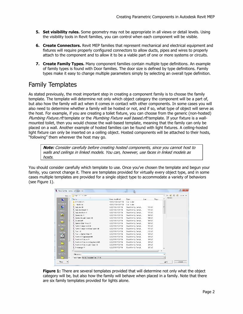
You should consider carefully which template to use. Once you’ve chosen the template and begun your
family, you cannot change it. There are templates provided for virtually every object type, and in some cases multiple templates are provided for a single object type to accommodate a variety of behaviors
(see Figure 1).
Figure 1: There are several templates provided that will determine not only what the object
category will be, but also how the family will behave when placed in a family. Note that there are six family templates provided for lights alone.
Creating Parametric Components in Autodesk Revit MEP
Page 3
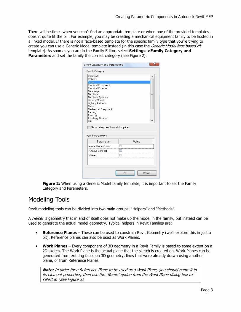
There will be times when you can’t find an appropriate template or when one of the provided templates doesn’t quite fit the bill. For example, you may be creating a mechanical equipment family to be hosted in
a linked model. If there is not a face-based template for the specific family type that you’re trying to create you can use a Generic Model template instead (in this case the Generic Model face based.rft template). As soon as you are in the Family Editor, select Settings->Family Category and
Parameters and set the family the correct category (see Figure 2).
Figure 2: When using a Generic Model family template, it is important to set the Family
Category and Parameters.
Modeling Tools
Revit modeling tools can be divided into two main groups: “Helpers” and “Methods”.
A Helper is geometry that in and of itself does not make up the model in the family, but instead can be
used to generate the actual model geometry. Typical helpers in Revit Families are:
• Reference Planes – These can be used to constrain Revit Geometry (we’ll explore this in just a
bit). Reference planes can also be used as Work Planes.
• Work Planes – Every component of 3D geometry in a Revit Family is based to some extent on a
2D sketch. The Work Plane is the actual plane that the sketch is created on. Work Planes can be
generated from existing faces on 3D geometry, lines that were already drawn using another
plane, or from Reference Planes.
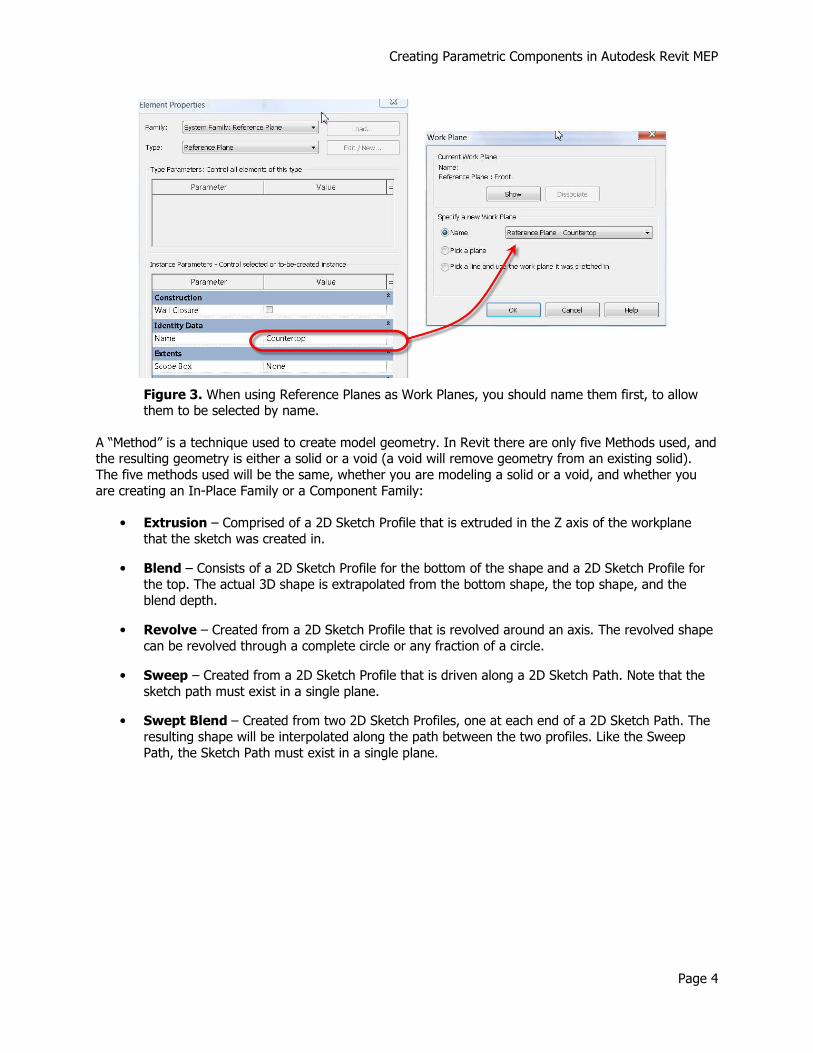
Note: In order for a Reference Plane to be used as a Work Plane, you should name it in its element properties, then use the “Name” option from the Work Plane dialog box to select it. (See Figure 3).
Creating Parametric Components in Autodesk Revit MEP
Page 4
Figure 3. When using Reference Planes as Work Planes, you should name them first, to allow them to be selected by name.
A “Method” is a technique used to create model geometry. In Revit there are only five Methods used, and the resulting geometry is either a solid or a void (a void will remove geometry from an existing solid).
The five methods used will be the same, whether you are modeling a solid or a void, and whether you
are creating an In-Place Family or a Component Family:
• Extrusion – Comprised of a 2D Sketch Profile that is extruded in the Z axis of the workplane
that the sketch was created in.
• Blend – Consists of a 2D Sketch Profile for the bottom of the shape and a 2D Sketch Profile for
the top. The actual 3D shape is extrapolated from the bottom shape, the top shape, and the
blend depth.
• Revolve – Created from a 2D Sketch Profile that is revolved around an axis. The revolved shape
can be revolved through a complete circle or any fraction of a circle.
• Sweep – Created from a 2D Sketch Profile that is driven along a 2D Sketch Path. Note that the
sketch path must exist in a single plane.
• Swept Blend – Created from two 2D Sketch Profiles, one at each end of a 2D Sketch Path. The
resulting shape will be interpolated along the path between the two profiles. Like the Sweep
Path, the Sketch Path must exist in a single plane.

Creating Parametric Components in Autodesk Revit MEP
Page 5
Figure 4. The five methods for creating solid or void geometry in Revit.
Parameters and Constraints
Parameters are at the heart of a successful Revit Family. While you don’t have to make a family parametric, doing so will allow for a single family to be flexible enough to address issues that otherwise
may take multiple families to handle. For example, by creating a parameter to control the height of a
wall-mounted toilet, you can accommodate both an ADA-compliant toilet’s dimensions with those of a standard toilet with a single family definition. In addition to controlling the dimensions of an object,
parameters can control visibility and materials, as well as a host of other types of data, including user-defined text properties for scheduling and annotation.
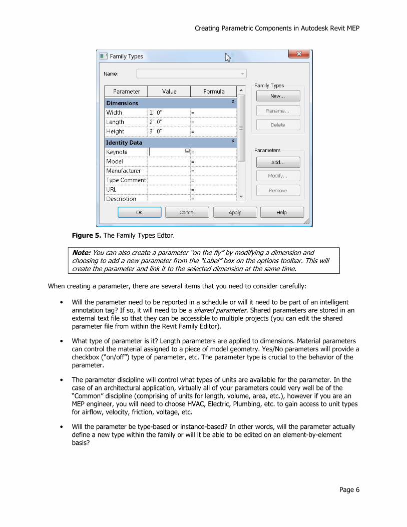
Parameters are typically created in the Family Editor (see Figure 5). The Family Editor actually has three
purposes:
1. Create, manage and modify parameters.
2. Create, manage and modify family types (more on this later)
3. Flex the family (test parameter values against the model geometry).
Creating Parametric Components in Autodesk Revit MEP
Page 6
Figure 5. The Family Types Edtor.
Note: You can also create a parameter “on the fly” by modifying a dimension and choosing to add a new parameter from the “Label” box on the options toolbar. This will create the parameter and link it to the selected dimension at the same time.
When creating a parameter, there are several items that you need to consider carefully:
• Will the parameter need to be reported in a schedule or will it need to be part of an intelligent
annotation tag? If so, it will need to be a shared parameter. Shared parameters are stored in an
external text file so that they can be accessible to multiple projects (you can edit the shared parameter file from within the Revit Family Editor).
• What type of parameter is it? Length parameters are applied to dimensions. Material parameters
can control the material assigned to a piece of model geometry. Yes/No parameters will provide a
checkbox (“on/off”) type of parameter, etc. The parameter type is crucial to the behavior of the parameter.
• The parameter discipline will control what types of units are available for the parameter. In the
case of an architectural application, virtually all of your parameters could very well be of the
“Common” discipline (comprising of units for length, volume, area, etc.), however if you are an MEP engineer, you will need to choose HVAC, Electric, Plumbing, etc. to gain access to unit types
for airflow, velocity, friction, voltage, etc.
• Will the parameter be type-based or instance-based? In other words, will the parameter actually
define a new type within the family or will it be able to be edited on an element-by-element basis?

Creating Parametric Components in Autodesk Revit MEP
Page 7
Figure 6. Consider carefully the properties of the parameters that you create.
Guidelines for Geometric Parameters and Constraints
When using parameters and constraints to control physical geometry, there are some simple but definite
do’s and dont’s:
• When applying a dimension parameter always dimension to reference planes. Never, under any
circumstances, should you dimension to an actual piece of geometry or a sketch line if you are going to use a parameter to control the dimension. Doing so will result in a “Constraints not
satisfied” error message. After assigning parameter dimensions to your reference planes, you can constrain (lock) the sketch geometry to the reference planes. The dimension parameter will
actually control the position of the reference planes, which will in turn control the position of the model geometry.
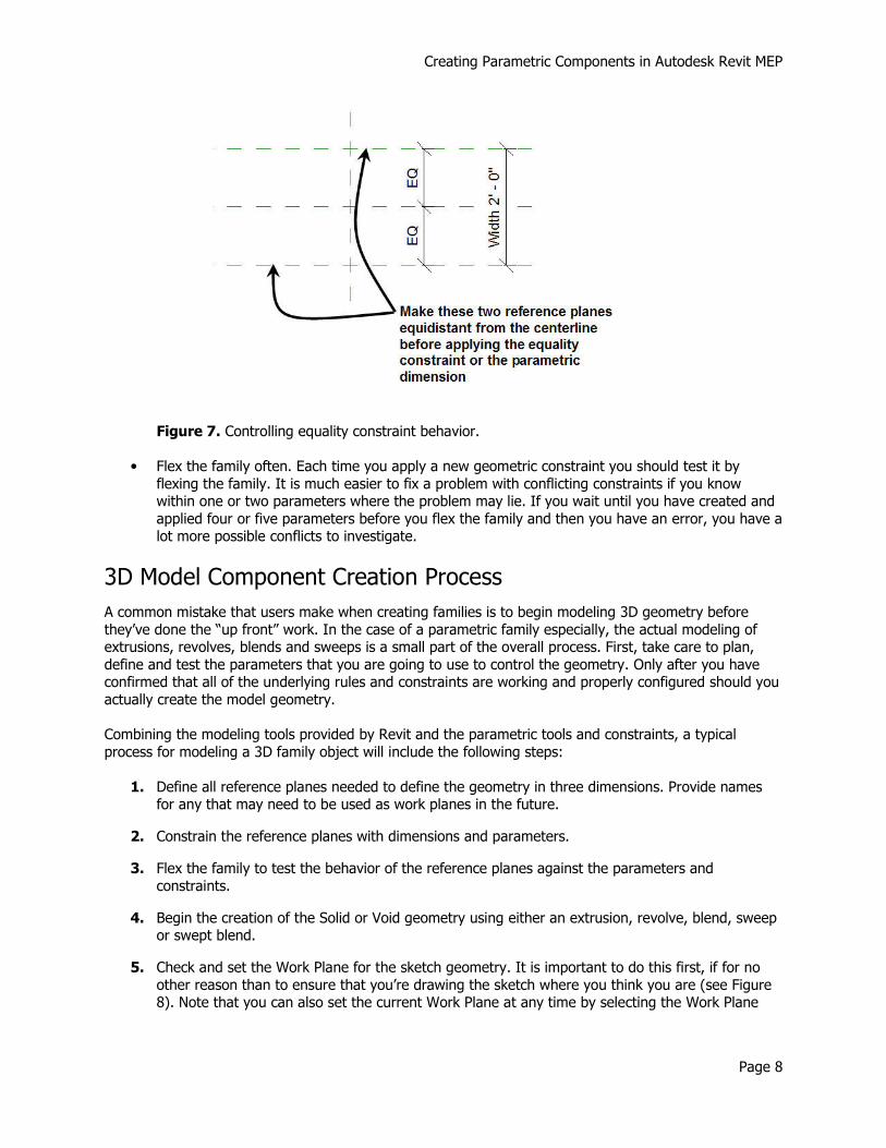
• When using an equality constraint to make geometry symmetrical about a center line while
allowing it to grow or shink about the centerline with an overall parametric constraint, create the
reference planes with the desired symmetry before applying the equality constraint. This will
remove any possible ambiguities from the equality constraint and will ensure proper behavior when the family is flexed later on. (See Figure 7).
Creating Parametric Components in Autodesk Revit MEP
Page 8
Figure 7. Controlling equality constraint behavior.
• Flex the family often. Each time you apply a new geometric constraint you should test it by
flexing the family. It is much easier to fix a problem with conflicting constraints if you know within one or two parameters where the problem may lie. If you wait until you have created and
applied four or five parameters before you flex the family and then you have an error, you have a lot more possible conflicts to investigate.
3D Model Component Creation Process
A common mistake that users make when creating families is to begin modeling 3D geometry before
they’ve done the “up front” work. In the case of a parametric family especially, the actual modeling of extrusions, revolves, blends and sweeps is a small part of the overall process. First, take care to plan,
define and test the parameters that you are going to use to control the geometry. Only after you have confirmed that all of the underlying rules and constraints are working and properly configured should you
actually create the model geometry.
Combining the modeling tools provided by Revit and the parametric tools and constraints, a typical
process for modeling a 3D family object will include the following steps:
1. Define all reference planes needed to define the geometry in three dimensions. Provide names for any that may need to be used as work planes in the future.
2. Constrain the reference planes with dimensions and parameters.
3. Flex the family to test the behavior of the reference planes against the parameters and
constraints.
4. Begin the creation of the Solid or Void geometry using either an extrusion, revolve, blend, sweep or swept blend.
5. Check and set the Work Plane for the sketch geometry. It is important to do this first, if for no
other reason than to ensure that you’re drawing the sketch where you think you are (see Figure 8). Note that you can also set the current Work Plane at any time by selecting the Work Plane
Creating Parametric Components in Autodesk Revit MEP
Page 9
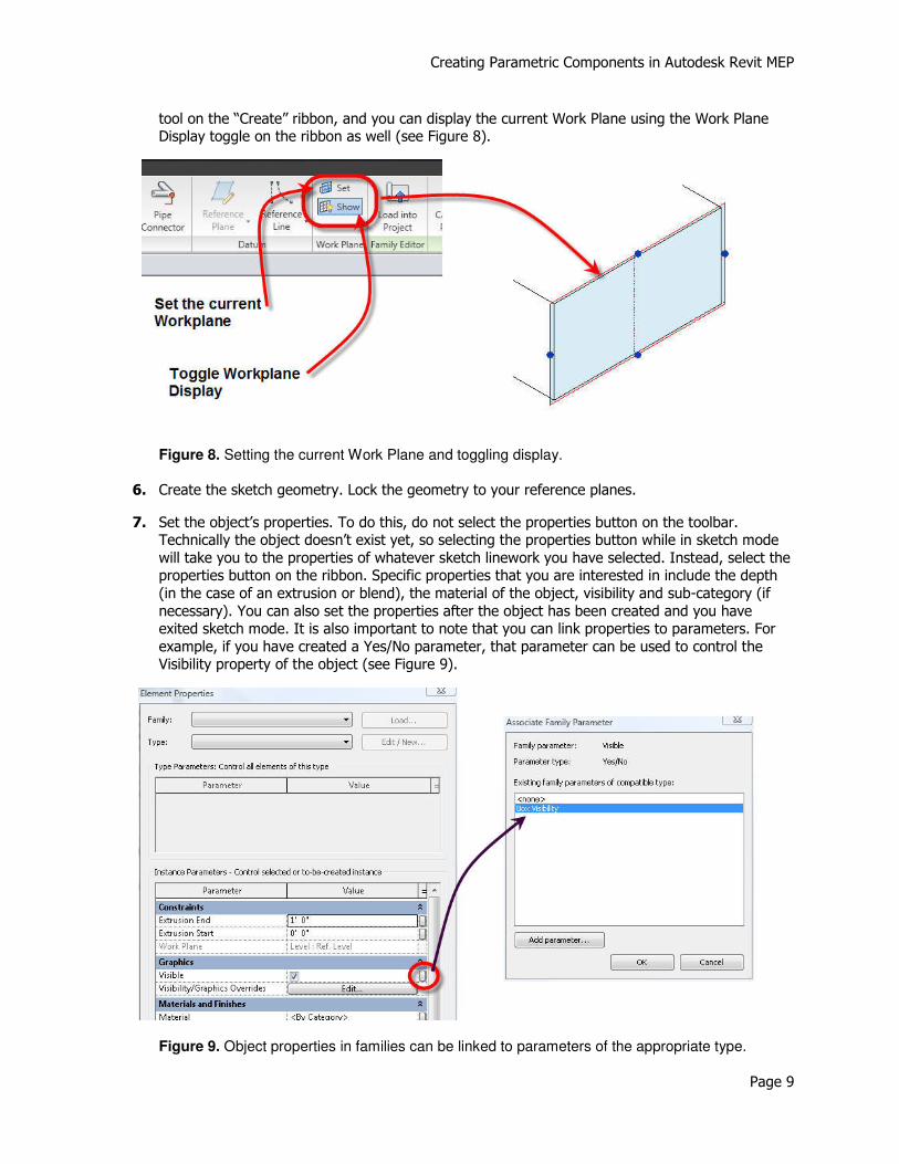
tool on the “Create” ribbon, and you can display the current Work Plane using the Work Plane Display toggle on the ribbon as well (see Figure 8).
Figure 8. Setting the current Work Plane and toggling display.
6. Create the sketch geometry. Lock the geometry to your reference planes.
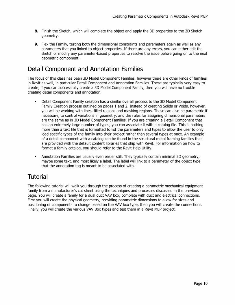
7. Set the object’s properties. To do this, do not select the properties button on the toolbar. Technically the object doesn’t exist yet, so selecting the properties button while in sketch mode
will take you to the properties of whatever sketch linework you have selected. Instead, select the properties button on the ribbon. Specific properties that you are interested in include the depth
(in the case of an extrusion or blend), the material of the object, visibility and sub-category (if
necessary). You can also set the properties after the object has been created and you have exited sketch mode. It is also important to note that you can link properties to parameters. For
example, if you have created a Yes/No parameter, that parameter can be used to control the Visibility property of the object (see Figure 9).
Figure 9. Object properties in families can be linked to parameters of the appropriate type.
Creating Parametric Components in Autodesk Revit MEP
Page 10
8. Finish the Sketch, which will complete the object and apply the 3D properties to the 2D Sketch geometry.
9. Flex the Family, testing both the dimensional constraints and parameters again as well as any
parameters that you linked to object properties. If there are any errors, you can either edit the sketch or modify any parameter-based properties to resolve the issue before going on to the next
geometric component.
Detail Component and Annotation Families
The focus of this class has been 3D Model Component Families, however there are other kinds of families in Revit as well, in particular Detail Component and Annotation Families. These are typically very easy to
create; if you can successfully create a 3D Model Component Family, then you will have no trouble creating detail components and annotation.
• Detail Component Family creation has a similar overall process to the 3D Model Component
Family Creation process outlined on pages 1 and 2. Instead of creating Solids or Voids, however,
you will be working with lines, filled regions and masking regions. These can also be parametric if necessary, to control variations in geometry, and the rules for assigning dimensional parameters
are the same as in 3D Model Component Families. If you are creating a Detail Component that has an extremely large number of types, you can associate it with a catalog file. This is nothing
more than a text file that is formatted to list the parameters and types to allow the user to only load specific types of the family into their project rather than several types at once. An example
of a detail component with a catalog can be found in the structural metal framing families that
are provided with the default content libraries that ship with Revit. For information on how to format a family catalog, you should refer to the Revit Help Utility.
• Annotation Families are usually even easier still. They typically contain minimal 2D geometry,
maybe some text, and most likely a label. The label will link to a parameter of the object type
that the annotation tag is meant to be associated with.
Tutorial
The following tutorial will walk you through the process of creating a parametric mechanical equipment
family from a manufacturer’s cut sheet using the techniques and processes discussed in the previous
page. You will create a family for a dual duct VAV box, complete with duct and electrical connections. First you will create the physical geometry, providing parametric dimensions to allow for sizes and
positioning of components to change based on the VAV box type, then you will create the connections. Finally, you will create the various VAV Box types and test them in a Revit MEP project.

Creating Parametric Components in Autodesk Revit MEP
Page 11
Dual Duct VAV Box Family Tutorial
Model 3240 “Blendmaster” Dual Duct VAV
Dimensional Data (inches)
Unit Size Inlet
Diameter cfm
Range W H L A
Outlet DW x DH
4 3 7/8 0-215
24 10 47 11 8 x 8 5 4 7/8 0-310
6 5 7/8 0-500
7 6 7/8 0-710 24 12 ½” 47 11 10 x 10
8 7 7/8 0-1000
9 8 7/8 0-1300 34 14 60 16 1/8 14 x 12
10 9 7/8 0-1435
12 11 7/8 0-2150 34 16 60 16 1/8 18 x 14
14 13 7/8 0-3060 42 18 72 20 1/8 22 x 16
Creating Parametric Components in Autodesk Revit MEP
Page 12
Introduction
Using the graphics and table on the preceding page, you will create a parametric VAV Box following the procedures and methods described in the first part of this document. A single Family will accommodate
all of the unit sizes listed in the Dimensional Data table. By simply changing the Type from one unit size
to another, all of the other parameters will update as well.
We will work from the values for the Unit Size 4 type until we have the entire model built, then we’ll
attach the connectors. As a final step we’ll create the rest of the Types and test in a Revit project file.
Start the Family
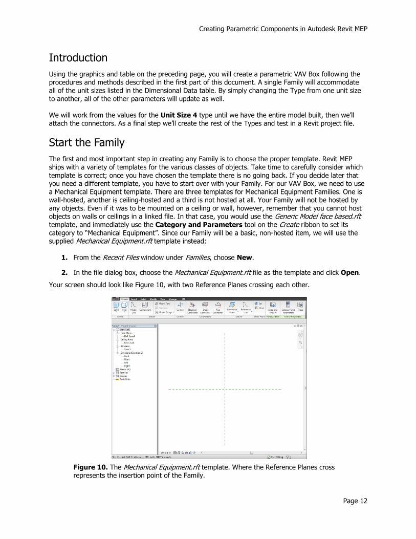
The first and most important step in creating any Family is to choose the proper template. Revit MEP
ships with a variety of templates for the various classes of objects. Take time to carefully consider which
template is correct; once you have chosen the template there is no going back. If you decide later that you need a different template, you have to start over with your Family. For our VAV Box, we need to use
a Mechanical Equipment template. There are three templates for Mechanical Equipment Families. One is wall-hosted, another is ceiling-hosted and a third is not hosted at all. Your Family will not be hosted by
any objects. Even if it was to be mounted on a ceiling or wall, however, remember that you cannot host objects on walls or ceilings in a linked file. In that case, you would use the Generic Model face based.rft template, and immediately use the Category and Parameters tool on the Create ribbon to set its category to “Mechanical Equipment”. Since our Family will be a basic, non-hosted item, we will use the supplied Mechanical Equipment.rft template instead:
1. From the Recent Files window under Families, choose New.
2. In the file dialog box, choose the Mechanical Equipment.rft file as the template and click Open.
Your screen should look like Figure 10, with two Reference Planes crossing each other.
Figure 10. The Mechanical Equipment.rft template. Where the Reference Planes cross represents the insertion point of the Family.
Creating Parametric Components in Autodesk Revit MEP
Page 13
Note: If you see an example Face or a Wall, you chose a hosted template by mistake. In that case you should close the file without saving and repeat Steps 1 and 2, taking care to choose the Mechanical Equipment.rft file.
Create the Model Geometry
The model geometry will be created in four stages:
• The main VAV Box Body, which will be symmetrically positioned in 3D around the “origin point”
defined by the crossing Reference Planes. This will place the elevation of the origin point at the
same elevation as the centerline of any connecting ductwork.
• The Outlet Duct Sleeve.
• The Inlet Duct Sleeves.
• The Control Boxes on the sides of the main VAV Box Body.
Modeling the VAV Box Body
Create all of the Reference Planes that are needed to define the geometry first, then assign them
dimensions and parameters.
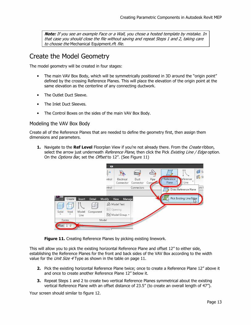
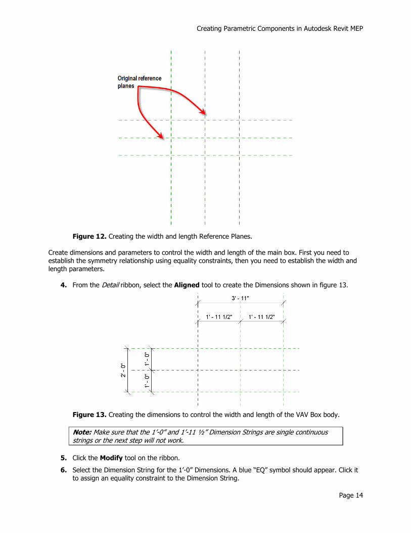
1. Navigate to the Ref Level Floorplan View if you’re not already there. From the Create ribbon, select the arrow just underneath Reference Plane, then click the Pick Existing Line / Edge option. On the Options Bar, set the Offset to 12”. (See Figure 11)
Figure 11. Creating Reference Planes by picking existing linework.
This will allow you to pick the existing horizontal Reference Plane and offset 12” to either side,
establishing the Reference Planes for the front and back sides of the VAV Box according to the width value for the Unit Size 4 Type as shown in the table on page 11.
2. Pick the existing horizontal Reference Plane twice; once to create a Reference Plane 12” above it and once to create another Reference Plane 12” below it.
3. Repeat Steps 1 and 2 to create two vertical Reference Planes symmetrical about the existing
vertical Reference Plane with an offset distance of 23.5” (to create an overall length of 47”).
Your screen should similar to figure 12.
Creating Parametric Components in Autodesk Revit MEP
Page 14
Figure 12. Creating the width and length Reference Planes.
Create dimensions and parameters to control the width and length of the main box. First you need to
establish the symmetry relationship using equality constraints, then you need to establish the width and
length parameters.
4. From the Detail ribbon, select the Aligned tool to create the Dimensions shown in figure 13.
Figure 13. Creating the dimensions to control the width and length of the VAV Box body.
Note: Make sure that the 1’-0” and 1’-11 ½” Dimension Strings are single continuous strings or the next step will not work.
5. Click the Modify tool on the ribbon.
6. Select the Dimension String for the 1’-0” Dimensions. A blue “EQ” symbol should appear. Click it
to assign an equality constraint to the Dimension String.
Creating Parametric Components in Autodesk Revit MEP
Page 15
This will ensure that if the overall dimension of 2’-0” changes, both of the Reference Planes defining the overall width of the box will move to maintain symmetry around the horizontal Reference Plane that
defines the origin.
7. Repeat Step 6 to assign the same constraint to the 1’-11 ½” Dimensions.
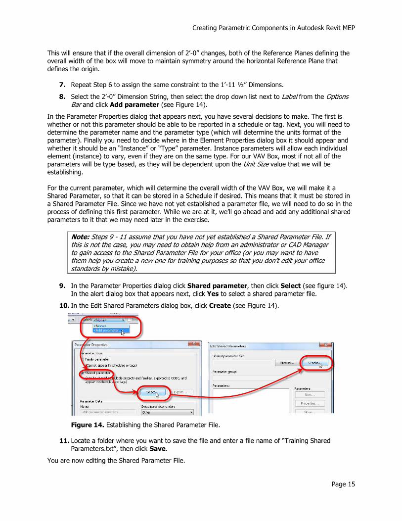
8. Select the 2’-0” Dimension String, then select the drop down list next to Label from the Options Bar and click Add parameter (see Figure 14).
In the Parameter Properties dialog that appears next, you have several decisions to make. The first is
whether or not this parameter should be able to be reported in a schedule or tag. Next, you will need to determine the parameter name and the parameter type (which will determine the units format of the
parameter). Finally you need to decide where in the Element Properties dialog box it should appear and
whether it should be an “Instance” or “Type” parameter. Instance parameters will allow each individual element (instance) to vary, even if they are on the same type. For our VAV Box, most if not all of the
parameters will be type based, as they will be dependent upon the Unit Size value that we will be establishing.
For the current parameter, which will determine the overall width of the VAV Box, we will make it a Shared Parameter, so that it can be stored in a Schedule if desired. This means that it must be stored in
a Shared Parameter File. Since we have not yet established a parameter file, we will need to do so in the
process of defining this first parameter. While we are at it, we’ll go ahead and add any additional shared parameters to it that we may need later in the exercise.
Note: Steps 9 - 11 assume that you have not yet established a Shared Parameter File. If this is not the case, you may need to obtain help from an administrator or CAD Manager to gain access to the Shared Parameter File for your office (or you may want to have them help you create a new one for training purposes so that you don’t edit your office standards by mistake).
9. In the Parameter Properties dialog click Shared parameter, then click Select (see figure 14).
In the alert dialog box that appears next, click Yes to select a shared parameter file.
10. In the Edit Shared Parameters dialog box, click Create (see Figure 14).
Figure 14. Establishing the Shared Parameter File.
11. Locate a folder where you want to save the file and enter a file name of “Training Shared
Parameters.txt”, then click Save.
You are now editing the Shared Parameter File.
Creating Parametric Components in Autodesk Revit MEP
Page 16
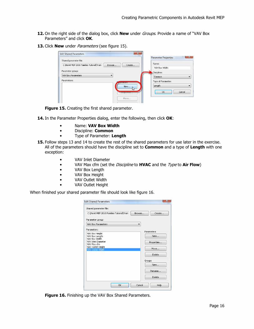
12. On the right side of the dialog box, click New under Groups. Provide a name of “VAV Box Parameters” and click OK.
13. Click New under Parameters (see figure 15).
Figure 15. Creating the first shared parameter.
14. In the Parameter Properties dialog, enter the following, then click OK:
• Name: VAV Box Width
• Discipline: Common
• Type of Parameter: Length
15. Follow steps 13 and 14 to create the rest of the shared parameters for use later in the exercise. All of the parameters should have the discipline set to Common and a type of Length with one
exception:
• VAV Inlet Diameter
• VAV Max cfm (set the Discipline to HVAC and the Type to Air Flow)
• VAV Box Length
• VAV Box Height
• VAV Outlet Width
• VAV Outlet Height
When finished your shared parameter file should look like figure 16.
Figure 16. Finishing up the VAV Box Shared Parameters.
Creating Parametric Components in Autodesk Revit MEP
Page 17
Note: Remember, only those parameters that may need to be reported in a Schedule or a Tag need to be Shared Parameters. In this exercise we may be going overboard just a bit, however if there is even the slightest chance that you may want a parameter available for scheduling and tagging you should make it shared.
16. Click OK to finish editing the Shared Parameter file.
17. Select VAV Box Width from the parameter list and click OK.
18. Finish up the first parameter by setting the remaining values according to those shown in Figure 17, then click OK.
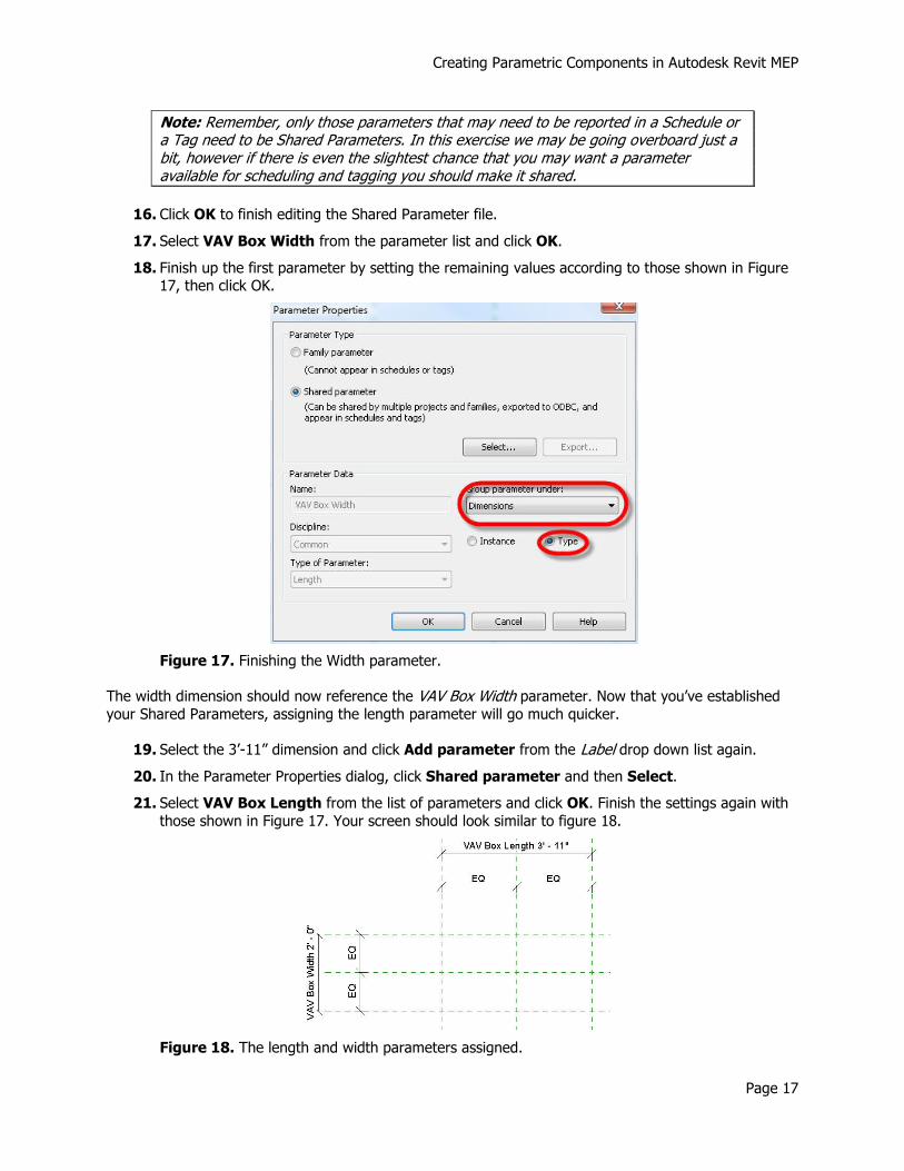
Figure 17. Finishing the Width parameter.
The width dimension should now reference the VAV Box Width parameter. Now that you’ve established
your Shared Parameters, assigning the length parameter will go much quicker.
19. Select the 3’-11” dimension and click Add parameter from the Label drop down list again.
20. In the Parameter Properties dialog, click Shared parameter and then Select.
21. Select VAV Box Length from the list of parameters and click OK. Finish the settings again with
those shown in Figure 17. Your screen should look similar to figure 18.
Figure 18. The length and width parameters assigned.
Creating Parametric Components in Autodesk Revit MEP
Page 18
This is a good opportunity to “flex the Family” and make sure that all parameters are functioning properly before moving on.
22. Pan your view so that your geometry is in the lower right area of your screen and you have some room for the next dialog in the upper right. You want to be able to make changes in the dialog
and monitor what the geometry is doing.
23. Select the Types tool from the Create ribbon.
24. Change the value for VAV Box Width to 3’-0” and the value for VAV Box Length to 5’-0” and click Apply.
The Reference Planes representing the width and length of the box should adjust, remaining symmetrical
around the centerline Reference Planes and the dimensions should update.
25. Click OK in the Family Types dialog, then click Undo until your geometry returns to the original values (be careful not to undo too far and remove your parameters).
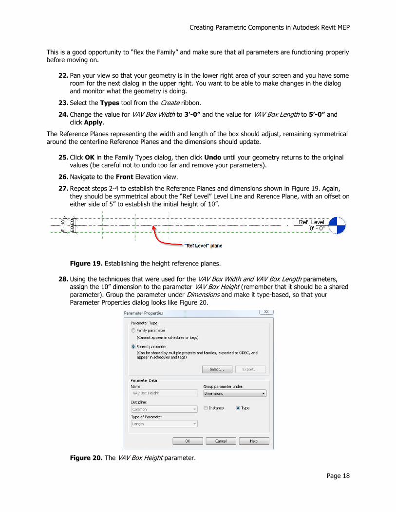
26. Navigate to the Front Elevation view.
27. Repeat steps 2-4 to establish the Reference Planes and dimensions shown in Figure 19. Again,
they should be symmetrical about the “Ref Level” Level Line and Rerence Plane, with an offset on either side of 5” to establish the initial height of 10”.
Figure 19. Establishing the height reference planes.
28. Using the techniques that were used for the VAV Box Width and VAV Box Length parameters, assign the 10” dimension to the parameter VAV Box Height (remember that it should be a shared
parameter). Group the parameter under Dimensions and make it type-based, so that your
Parameter Properties dialog looks like Figure 20.
Figure 20. The VAV Box Height parameter.
Creating Parametric Components in Autodesk Revit MEP
Page 19
29. Flex the family to test the VAV Box Height parameter by repeating steps 22-25. Make sure to return the parameter to the original value of 10” when done.
Now that you’ve set up all of the Reference Planes and parameters to control the main VAV Box geometry, it’s finally time to actually do some modeling. In preparation for this, you need to determine
where your Work Plane for the sketch geometry will be. For the VAV Box Body, you will use the
Reference Plane that defines the bottom of the box. In order for a Reference Plane to be used as a Work Plane, you should provide it a name.
30. Select the bottom Reference Plane, then click Element Properties from the ribbon.
31. In the Element Properties dialog, enter “VAV Box Bottom” next to Name under Identity Data, then click OK.
32. Navigate to the Ref. Level Floorplan view.
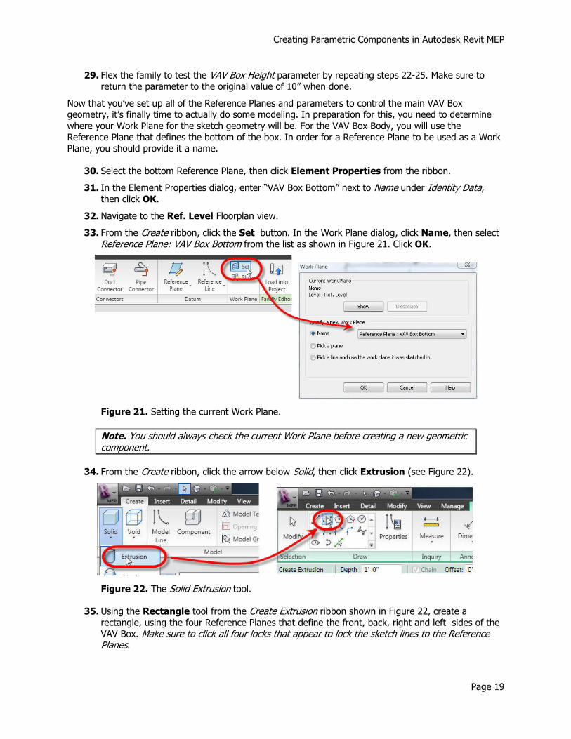
33. From the Create ribbon, click the Set button. In the Work Plane dialog, click Name, then select
Reference Plane: VAV Box Bottom from the list as shown in Figure 21. Click OK.
Figure 21. Setting the current Work Plane.
Note. You should always check the current Work Plane before creating a new geometric component.
34. From the Create ribbon, click the arrow below Solid, then click Extrusion (see Figure 22).
Figure 22. The Solid Extrusion tool.
35. Using the Rectangle tool from the Create Extrusion ribbon shown in Figure 22, create a rectangle, using the four Reference Planes that define the front, back, right and left sides of the
VAV Box. Make sure to click all four locks that appear to lock the sketch lines to the Reference Planes.

Creating Parametric Components in Autodesk Revit MEP
Page 20
With the sketch completed, your screen should look similar to Figure 23. (If you have picked something other than a sketch line since locking them, the locks will no longer be visible.)
Figure 23. The completed VAV Box body sketch.
36. From the Create Extrusion ribbon, click Extrusion Properties (see Figure 24).
In the Instance Properties dialog, note that the extrusion starts at an elevation of 0” relative to the Work
Plane, and ends at a distance of 1’-0” from the Work Plane. You need to link this to the VAV Box Height parameter.
37. Click the small button to the right of the Extrusion End value (see Figure 24).
Figure 24. Linking the Extrusion End value to the VAV Box Height parameter.
Creating Parametric Components in Autodesk Revit MEP
Page 21
38. In the Associate Family Parameter dialog, click the VAV Box Height parameter and click OK.
Note that the Extrusion End value is now greyed out, but is also equal to the value of the VAV Box Height
parameter (10”). This property will be controlled by that parameter from now on.
39. Click OK to exit the Instance Properties dialog.
40. From the right side of the Create Extrusion ribbon, click Finish Extrusion.
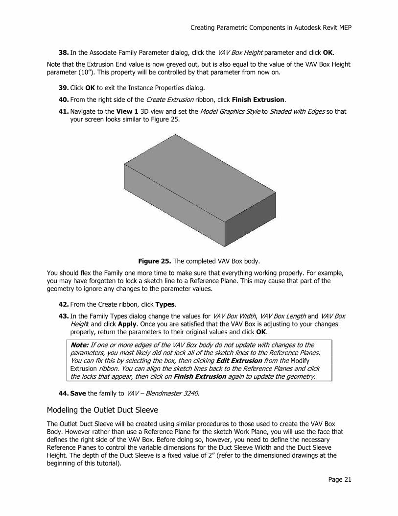
41. Navigate to the View 1 3D view and set the Model Graphics Style to Shaded with Edges so that your screen looks similar to Figure 25.
Figure 25. The completed VAV Box body.
You should flex the Family one more time to make sure that everything working properly. For example,
you may have forgotten to lock a sketch line to a Reference Plane. This may cause that part of the geometry to ignore any changes to the parameter values.
42. From the Create ribbon, click Types.
43. In the Family Types dialog change the values for VAV Box Width, VAV Box Length and VAV Box Height and click Apply. Once you are satisfied that the VAV Box is adjusting to your changes properly, return the parameters to their original values and click OK.
Note: If one or more edges of the VAV Box body do not update with changes to the parameters, you most likely did not lock all of the sketch lines to the Reference Planes. You can fix this by selecting the box, then clicking Edit Extrusion from the Modify Extrusion ribbon. You can align the sketch lines back to the Reference Planes and click the locks that appear, then click on Finish Extrusion again to update the geometry.
44. Save the family to VAV – Blendmaster 3240.
Modeling the Outlet Duct Sleeve
The Outlet Duct Sleeve will be created using similar procedures to those used to create the VAV Box Body. However rather than use a Reference Plane for the sketch Work Plane, you will use the face that
defines the right side of the VAV Box. Before doing so, however, you need to define the necessary
Reference Planes to control the variable dimensions for the Duct Sleeve Width and the Duct Sleeve Height. The depth of the Duct Sleeve is a fixed value of 2” (refer to the dimensioned drawings at the
beginning of this tutorial).
Creating Parametric Components in Autodesk Revit MEP
Page 22
1. Navigate to the Right Elevation view.
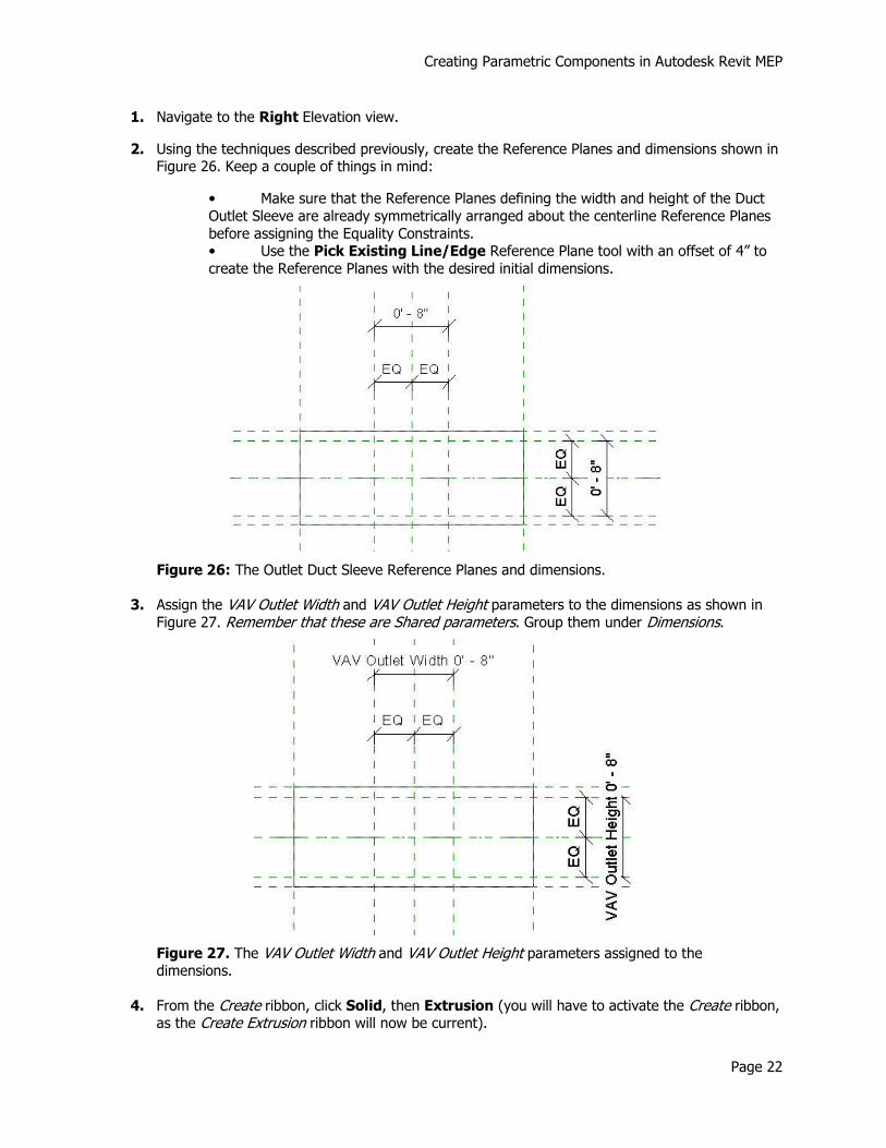
2. Using the techniques described previously, create the Reference Planes and dimensions shown in Figure 26. Keep a couple of things in mind:
• Make sure that the Reference Planes defining the width and height of the Duct
Outlet Sleeve are already symmetrically arranged about the centerline Reference Planes
before assigning the Equality Constraints. • Use the Pick Existing Line/Edge Reference Plane tool with an offset of 4” to
create the Reference Planes with the desired initial dimensions.
Figure 26: The Outlet Duct Sleeve Reference Planes and dimensions.
3. Assign the VAV Outlet Width and VAV Outlet Height parameters to the dimensions as shown in
Figure 27. Remember that these are Shared parameters. Group them under Dimensions.
Figure 27. The VAV Outlet Width and VAV Outlet Height parameters assigned to the dimensions.
4. From the Create ribbon, click Solid, then Extrusion (you will have to activate the Create ribbon, as the Create Extrusion ribbon will now be current).
Creating Parametric Components in Autodesk Revit MEP
Page 23
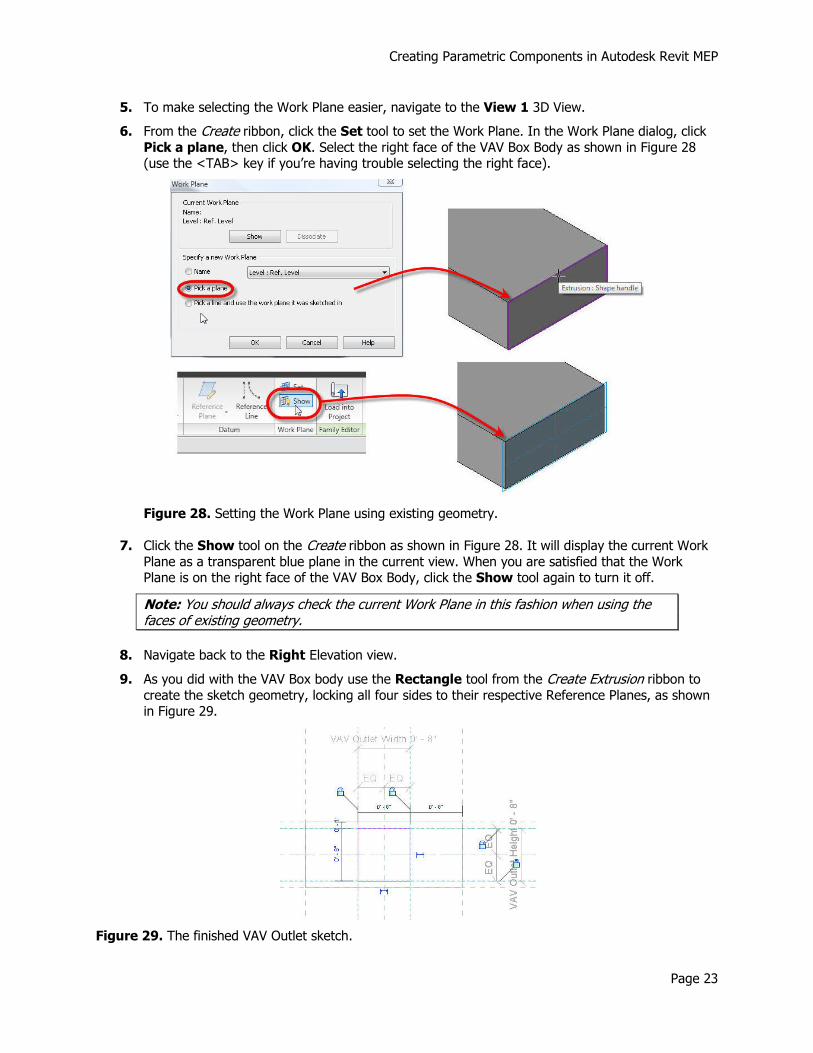
5. To make selecting the Work Plane easier, navigate to the View 1 3D View.
6. From the Create ribbon, click the Set tool to set the Work Plane. In the Work Plane dialog, click
Pick a plane, then click OK. Select the right face of the VAV Box Body as shown in Figure 28 (use the <TAB> key if you’re having trouble selecting the right face).
Figure 28. Setting the Work Plane using existing geometry.
7. Click the Show tool on the Create ribbon as shown in Figure 28. It will display the current Work
Plane as a transparent blue plane in the current view. When you are satisfied that the Work Plane is on the right face of the VAV Box Body, click the Show tool again to turn it off.
Note: You should always check the current Work Plane in this fashion when using the faces of existing geometry.
8. Navigate back to the Right Elevation view.
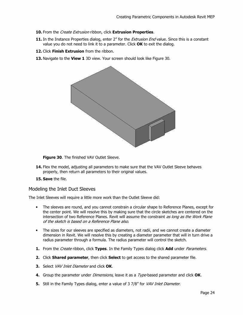
9. As you did with the VAV Box body use the Rectangle tool from the Create Extrusion ribbon to create the sketch geometry, locking all four sides to their respective Reference Planes, as shown in Figure 29.
Figure 29. The finished VAV Outlet sketch.
Creating Parametric Components in Autodesk Revit MEP
Page 24
10. From the Create Extrusion ribbon, click Extrusion Properties.
11. In the Instance Properties dialog, enter 2” for the Extrusion End value. Since this is a constant value you do not need to link it to a parameter. Click OK to exit the dialog.
12. Click Finish Extrusion from the ribbon.
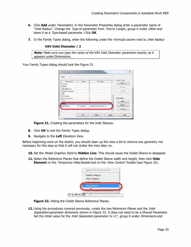
13. Navigate to the View 1 3D view. Your screen should look like Figure 30.
Figure 30. The finished VAV Outlet Sleeve.
14. Flex the model, adjusting all parameters to make sure that the VAV Outlet Sleeve behaves
properly, then return all parameters to their original values.
15. Save the file.
Modeling the Inlet Duct Sleeves
The Inlet Sleeves will require a little more work than the Outlet Sleeve did:
• The sleeves are round, and you cannot constrain a circular shape to Reference Planes, except for
the center point. We will resolve this by making sure that the circle sketches are centered on the
intersection of two Reference Planes. Revit will assume the constraint as long as the Work Plane of the sketch is based on a Reference Plane also.
• The sizes for our sleeves are specified as diameters, not radii, and we cannot create a diameter
dimension in Revit. We will resolve this by creating a diameter parameter that will in turn drive a
radius parameter through a formula. The radius parameter will control the sketch.
1. From the Create ribbon, click Types. In the Family Types dialog click Add under Parameters.
2. Click Shared parameter, then click Select to get access to the shared parameter file.
3. Select VAV Inlet Diameter and click OK.
4. Group the parameter under Dimensions, leave it as a Type-based parameter and click OK.
5. Still in the Family Types dialog, enter a value of 3 7/8” for VAV Inlet Diameter.
Creating Parametric Components in Autodesk Revit MEP
Page 25
6. Click Add under Parameters. In the Parameter Properties dialog enter a parameter name of “Inlet Radius”. Change the Type of parameter from Text to Length, group it under Other and leave it as a Type-based parameter. Click OK.
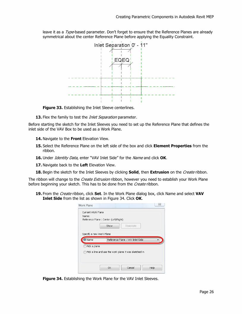
7. In the Family Types dialog, enter the following under the Formula column next to Inlet Radius:
VAV Inlet Diameter / 2
Note: Make sure you type the name of the VAV Inlet Diameter parameter exactly as it appears under Dimensions.
Your Family Types dialog should look like Figure 31.
Figure 31. Creating the parameters for the Inlet Sleeves.
8. Click OK to exit the Family Types dialog.
9. Navigate to the Left Elevation View.
Before beginning work on the sketch, you should clean up the view a bit to remove any geometry not necessary for this step so that it will not clutter the view later on.
10. Set the Model Graphics Style to Hidden Line. This should cause the Outlet Sleeve to disappear
11. Select the Reference Planes that define the Outlet Sleeve width and height, then click Hide Element on the Temporary Hide/Isolate tool on the View Control Toolbar (see Figure 32).
Figure 32. Hiding the Outlet Sleeve Reference Planes.
12. Using the procedures covered previously, create the two Reference Planes and the Inlet Separation parameter dimension shown in Figure 33. It does not need to be a Shared Parameter.
Set the initial value for the Inlet Separation parameter to 11”, group it under Dimensions and
Creating Parametric Components in Autodesk Revit MEP
Page 26
leave it as a Type-based parameter. Don’t forget to ensure that the Reference Planes are already symmetrical about the center Reference Plane before applying the Equality Constraint.
Figure 33. Establishing the Inlet Sleeve centerlines.
13. Flex the family to test the Inlet Separation parameter.
Before starting the sketch for the Inlet Sleeves you need to set up the Reference Plane that defines the
inlet side of the VAV Box to be used as a Work Plane.
14. Navigate to the Front Elevation View.
15. Select the Reference Plane on the left side of the box and click Element Properties from the ribbon.
16. Under Identity Data, enter “VAV Inlet Side” for the Name and click OK.
17. Navigate back to the Left Elevation View.
18. Begin the sketch for the Inlet Sleeves by clicking Solid, then Extrusion on the Create ribbon.
The ribbon will change to the Create Extrusion ribbon, however you need to establish your Work Plane before beginning your sketch. This has to be done from the Create ribbon.
19. From the Create ribbon, click Set. In the Work Plane dialog box, click Name and select VAV Inlet Side from the list as shown in Figure 34. Click OK.
Figure 34. Establishing the Work Plane for the VAV Inlet Sleeves.
Creating Parametric Components in Autodesk Revit MEP
Page 27
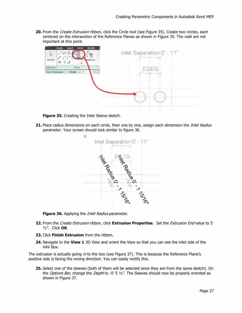
20. From the Create Extrusion ribbon, click the Circle tool (see Figure 35). Create two circles, each centered on the intersection of the Reference Planes as shown in Figure 35. The radii are not
important at this point.
Figure 35. Creating the Inlet Sleeve sketch.
21. Place radius dimensions on each circle, then one by one, assign each dimension the Inlet Radius parameter. Your screen should look similar to figure 36.
Figure 36. Applying the Inlet Radius parameter.
22. From the Create Extrusion ribbon, click Extrusion Properties. Set the Extrusion End value to 5 ½”. Click OK.
23. Click Finish Extrusion from the ribbon.
24. Navigate to the View 1 3D View and orient the View so that you can see the inlet side of the
VAV Box.
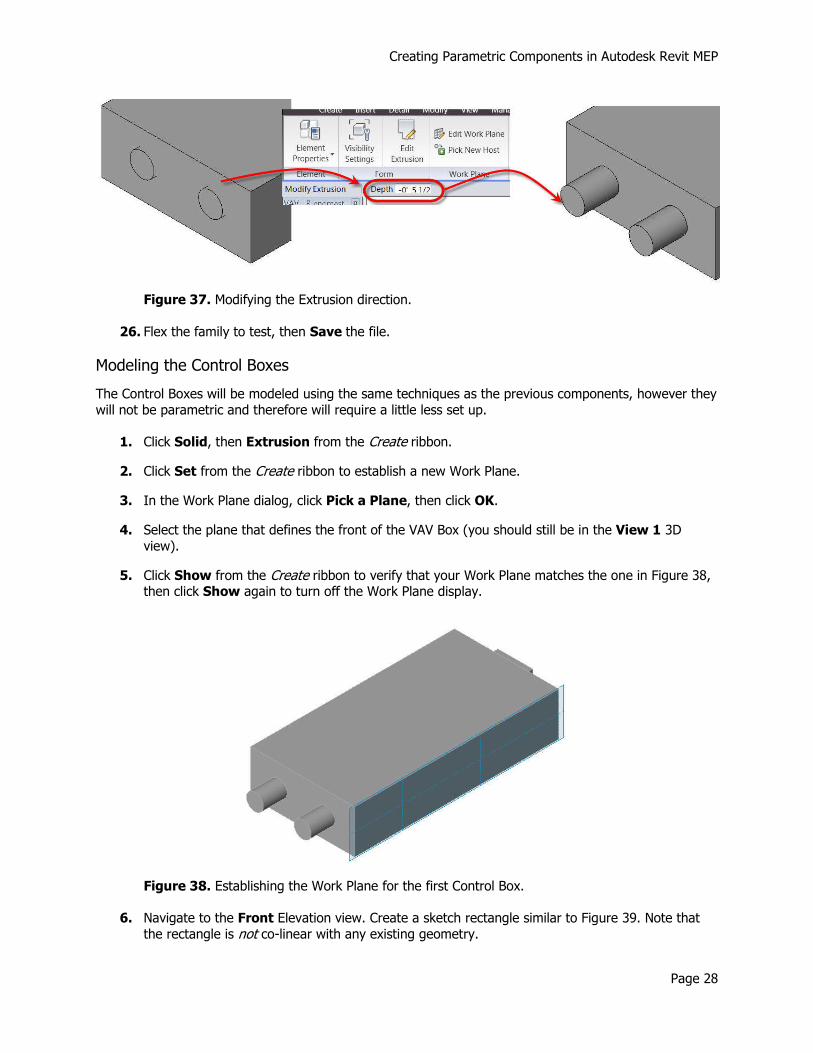
The extrusion is actually going in to the box (see Figure 37). This is because the Reference Plane’s positive side is facing the wrong direction. You can easily rectify this.
25. Select one of the sleeves (both of them will be selected since they are from the same sketch). On
the Options Bar, change the Depth to -0’ 5 ½”. The Sleeves should now be properly oriented as
shown in Figure 37.
Creating Parametric Components in Autodesk Revit MEP
Page 28
Figure 37. Modifying the Extrusion direction.
26. Flex the family to test, then Save the file.
Modeling the Control Boxes
The Control Boxes will be modeled using the same techniques as the previous components, however they
will not be parametric and therefore will require a little less set up.
1. Click Solid, then Extrusion from the Create ribbon.
2. Click Set from the Create ribbon to establish a new Work Plane.
3. In the Work Plane dialog, click Pick a Plane, then click OK.
4. Select the plane that defines the front of the VAV Box (you should still be in the View 1 3D
view).
5. Click Show from the Create ribbon to verify that your Work Plane matches the one in Figure 38, then click Show again to turn off the Work Plane display.
Figure 38. Establishing the Work Plane for the first Control Box.
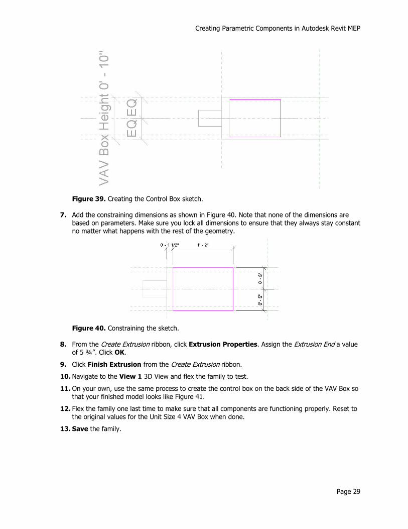
6. Navigate to the Front Elevation view. Create a sketch rectangle similar to Figure 39. Note that
the rectangle is not co-linear with any existing geometry.
Creating Parametric Components in Autodesk Revit MEP
Page 29
Figure 39. Creating the Control Box sketch.
7. Add the constraining dimensions as shown in Figure 40. Note that none of the dimensions are
based on parameters. Make sure you lock all dimensions to ensure that they always stay constant no matter what happens with the rest of the geometry.
Figure 40. Constraining the sketch.
8. From the Create Extrusion ribbon, click Extrusion Properties. Assign the Extrusion End a value of 5 ¾”. Click OK.
9. Click Finish Extrusion from the Create Extrusion ribbon.
10. Navigate to the View 1 3D View and flex the family to test.
11. On your own, use the same process to create the control box on the back side of the VAV Box so
that your finished model looks like Figure 41.
12. Flex the family one last time to make sure that all components are functioning properly. Reset to
the original values for the Unit Size 4 VAV Box when done.
13. Save the family.
Creating Parametric Components in Autodesk Revit MEP
Page 30
Figure 41. The finished VAV Box geometry.
Attach the Connectors
Connectors are the objects that give your Family it’s MEP “intelligence”. They provide points for
connecting ducts, pipes and wiring to the component, and are what allow for the component to be a part of an HVAC, Piping or Electrical System or Circuit.
Attach the Outlet Duct Connector
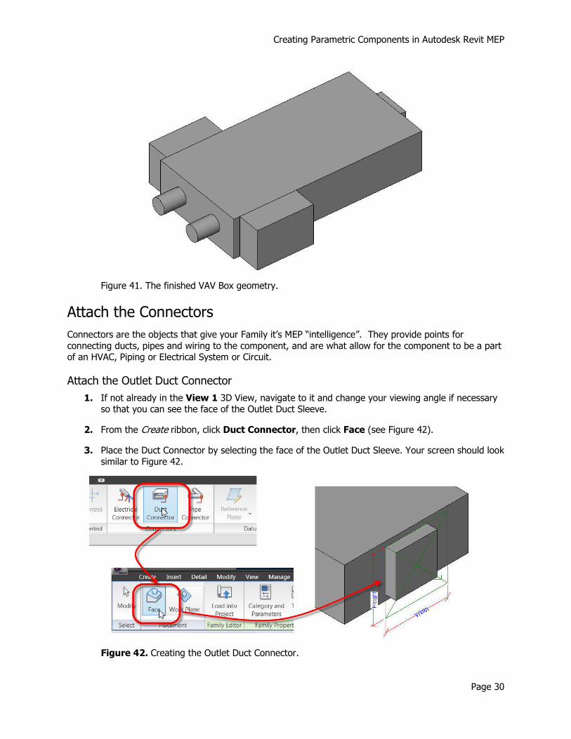
1. If not already in the View 1 3D View, navigate to it and change your viewing angle if necessary so that you can see the face of the Outlet Duct Sleeve.
2. From the Create ribbon, click Duct Connector, then click Face (see Figure 42).
3. Place the Duct Connector by selecting the face of the Outlet Duct Sleeve. Your screen should look
similar to Figure 42.
Figure 42. Creating the Outlet Duct Connector.
Creating Parametric Components in Autodesk Revit MEP
Page 31
Note: If you want your Connector to be centered on a face, use the Face option. If you want to control its position with dimensions, use the Work Plane option.
Once the Connector has been placed, you need to define its properties, including its size.
4. Click Modify on the ribbon, then select the Connector you just placed. Note that there is a “+” sign next to the Width and Height dimensions. Click the + sign next to Width. In the list of existing parameters, click VAV Outlet Width, then click OK. Repeat the process to assign the
VAV Outlet Height parameter to the Height value of the connector.
5. With the Connector still selected, Click Element Properties from the ribbon. In the Instance
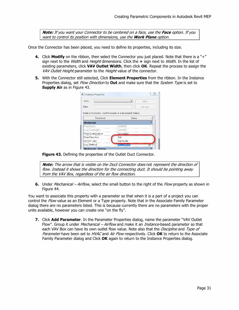
Properties dialog, set Flow Direction to Out and make sure that the System Type is set to Supply Air as in Figure 43.
Figure 43. Defining the properties of the Outlet Duct Connector.
Note: The arrow that is visible on the Duct Connector does not represent the direction of flow. Instead it shows the direction for the connecting duct. It should be pointing away from the VAV Box, regardless of the air flow direction.
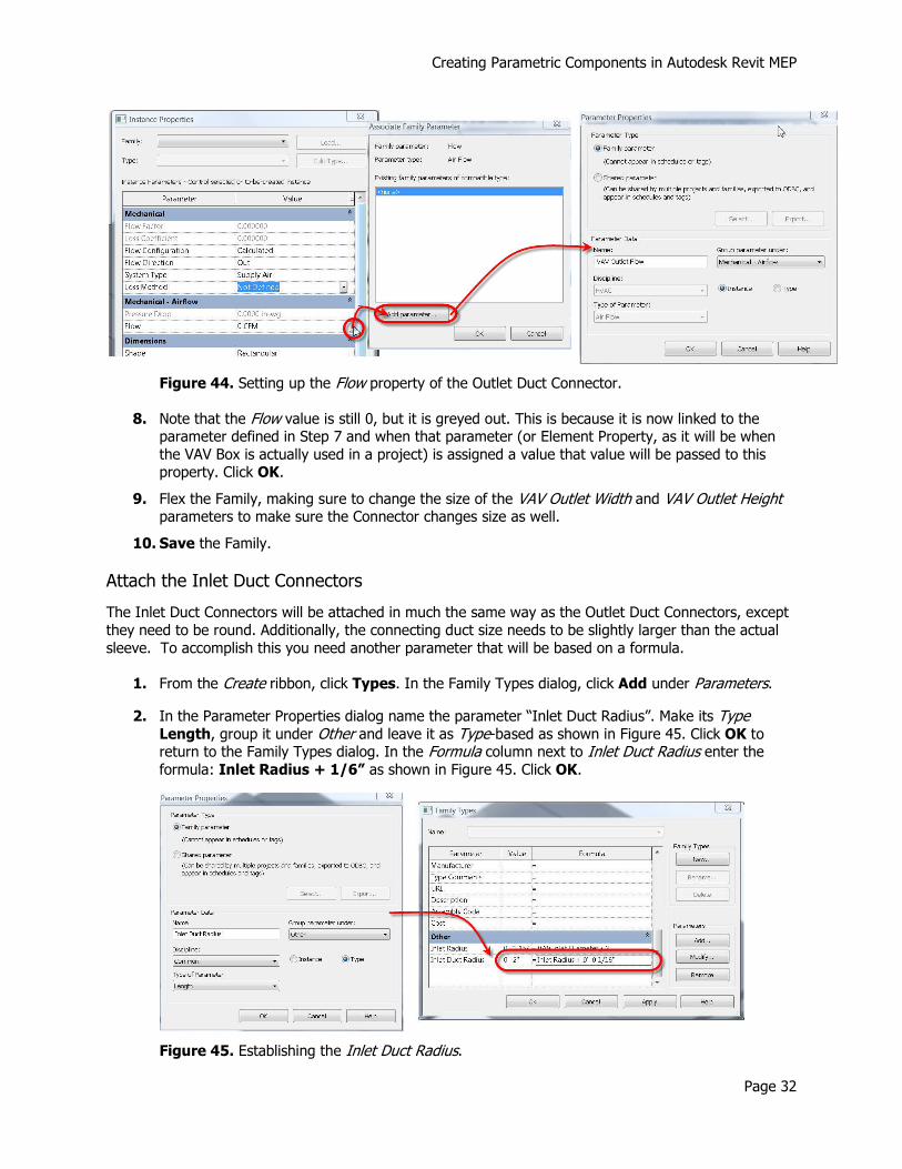
6. Under Mechanical – Airflow, select the small button to the right of the Flow property as shown in Figure 44.
You want to associate this property with a parameter so that when it is a part of a project you can control the Flow value as an Element or a Type property. Note that in the Associate Family Parameter
dialog there are no parameters listed. This is because currently there are no parameters with the proper
units available, however you can create one “on the fly”.
7. Click Add Parameter. In the Parameter Properties dialog, name the parameter “VAV Outlet
Flow”. Group it under Mechanical – Airflow and make it an Instance-based parameter so that each VAV Box can have its own outlet flow value. Note also that the Discipline and Type of Parameter have been set to HVAC and Air Flow respectively. Click OK to return to the Associate Family Parameter dialog and Click OK again to return to the Instance Properties dialog.
Creating Parametric Components in Autodesk Revit MEP
Page 32
Figure 44. Setting up the Flow property of the Outlet Duct Connector.
8. Note that the Flow value is still 0, but it is greyed out. This is because it is now linked to the parameter defined in Step 7 and when that parameter (or Element Property, as it will be when
the VAV Box is actually used in a project) is assigned a value that value will be passed to this property. Click OK.
9. Flex the Family, making sure to change the size of the VAV Outlet Width and VAV Outlet Height parameters to make sure the Connector changes size as well.
10. Save the Family.
Attach the Inlet Duct Connectors
The Inlet Duct Connectors will be attached in much the same way as the Outlet Duct Connectors, except
they need to be round. Additionally, the connecting duct size needs to be slightly larger than the actual
sleeve. To accomplish this you need another parameter that will be based on a formula.
1. From the Create ribbon, click Types. In the Family Types dialog, click Add under Parameters.
2. In the Parameter Properties dialog name the parameter “Inlet Duct Radius”. Make its Type Length, group it under Other and leave it as Type-based as shown in Figure 45. Click OK to return to the Family Types dialog. In the Formula column next to Inlet Duct Radius enter the formula: Inlet Radius + 1/6” as shown in Figure 45. Click OK.
Figure 45. Establishing the Inlet Duct Radius.
Creating Parametric Components in Autodesk Revit MEP
Page 33
3. Change your view angle in the View 1 3D View so that you are looking at the Inlet Sleeves.
4. Click Duct Connector from the Create ribbon. Click Face from the ribbon and pick one of the
Inlet Sleeve faces.
Duct Connectors will always be placed as rectangular connectors initially. You need to modify the
properties of the Connector to change it to round.
5. Click Modify on the ribbon, then select the Duct Connector.
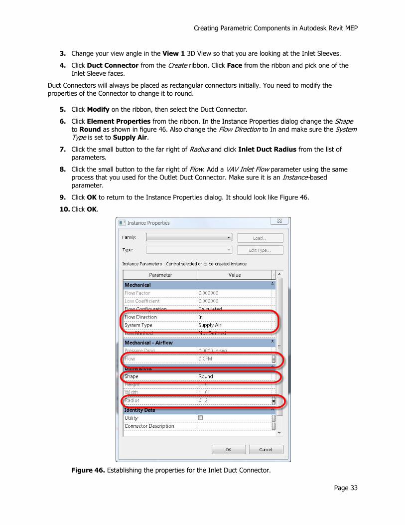
6. Click Element Properties from the ribbon. In the Instance Properties dialog change the Shape to Round as shown in figure 46. Also change the Flow Direction to In and make sure the System Type is set to Supply Air.
7. Click the small button to the far right of Radius and click Inlet Duct Radius from the list of
parameters.
8. Click the small button to the far right of Flow. Add a VAV Inlet Flow parameter using the same
process that you used for the Outlet Duct Connector. Make sure it is an Instance-based parameter.
9. Click OK to return to the Instance Properties dialog. It should look like Figure 46.
10. Click OK.
Figure 46. Establishing the properties for the Inlet Duct Connector.
Creating Parametric Components in Autodesk Revit MEP
Page 34
11. Follow Steps 4-9 to add a duct connector to the other Inlet Sleeve.
12. Flex the Family to make sure the connectors maintain the correct radius, then Save the Family.
Attach the Power Connector
Power Connectors are similar to Duct and Pipe Connectors, except that they don’t have a size or shape.
1. From the Create ribbon click Electrical Connector, then click Face from the ribbon.
2. Click the face of the Control Box on the front of the VAV Box. Don’t worry if the connector seems
large. It will not be visible when placed in a project.
3. Click Modify on the ribbon, then select the Electrical Connector. Click Element Properties.
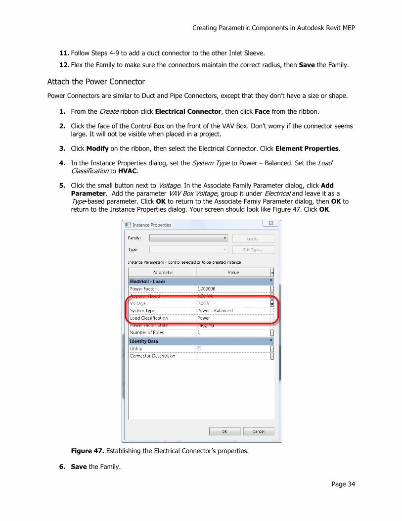
4. In the Instance Properties dialog, set the System Type to Power – Balanced. Set the Load Classification to HVAC.
5. Click the small button next to Voltage. In the Associate Family Parameter dialog, click Add
Parameter. Add the parameter VAV Box Voltage, group it under Electrical and leave it as a Type-based parameter. Click OK to return to the Associate Famiy Parameter dialog, then OK to
return to the Instance Properties dialog. Your screen should look like Figure 47. Click OK.
Figure 47. Establishing the Electrical Connector’s properties.
6. Save the Family.

Creating Parametric Components in Autodesk Revit MEP
Page 35
Create Family Types
Once the model has been created and the connectors placed, you can finish the Family by creating all of the Types needed for the final VAV Blendmaster. In this example, the Unit Size value is what determines
the values of all of the other Type-based parameters. These values are documented in the table on page
11 of this document. Before creating the Family Types however, you need to define one more parameter that will need to be assigned to each VAV Box type, to represent the maximum flow value.
1. From the Create ribbon, click Types. In the Family Types dialog, click Add under Parameters.
2. In the Parameter Properties dialog, click Shared parameter, then click Select. From the list of shared parameters click VAV Max cfm, then click OK. Group the parameter under Mechanical – Airflow and leave it as a Type-based parameter as shown in Figure 48. Click OK to return to the Family Types dialog.
Figure 48. Establishing the VAV Box Max cfm parameter.
Now that you have all of the necessary parameters defined you can create the Family Types.
3. Click New under Family Types. In the Name box enter Unit Size 4 for the first Type.
4. Enter the following parameter values:
Parameter Value
VAV Max cfm 215
VAV Outlet Width 0’-8”
VAV Outlet Height 0’-8”
VAV Inlet Diameter 0’-3 7/8”
VAV Box Width 2’-0”
VAV Box Length 3’-11”
VAV Box Height 0’-10”
Inlet Separation 0’-11”
VAV Box Voltage 208
Creating Parametric Components in Autodesk Revit MEP
Page 36
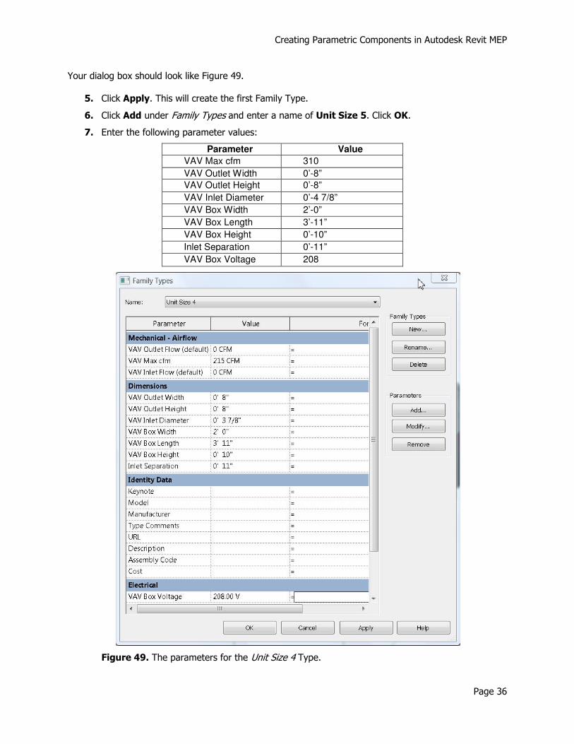
Your dialog box should look like Figure 49.
5. Click Apply. This will create the first Family Type.
6. Click Add under Family Types and enter a name of Unit Size 5. Click OK.
7. Enter the following parameter values:
Parameter Value
VAV Max cfm 310
VAV Outlet Width 0’-8”
VAV Outlet Height 0’-8”
VAV Inlet Diameter 0’-4 7/8”
VAV Box Width 2’-0”
VAV Box Length 3’-11”
VAV Box Height 0’-10”
Inlet Separation 0’-11”
VAV Box Voltage 208
Figure 49. The parameters for the Unit Size 4 Type.
Creating Parametric Components in Autodesk Revit MEP
Page 37
8. Click Apply to create the Unit Size 5 Type.
9. Continue creating the rest of the Types, using the values in the table on page 11, following the
procedures in Steps 6-8. When you are done, click OK to leave the Family Types dialog box.
Note: When creating the Family Types, you are also flexing the model. This is a good chance to catch any last minute errors with your parameters.
10. Save the Family.
Test the Family
To test your VAV Box, simply create a new Project, then add Mechanical Equipment from the Home Ribbon. Load your VAV - Blendmaster 3240 Family and place it as you would any other VAV Box. You should be able to connect ducts to it like any other Mechanical component, and you should be able to add it to a Supply system or an Electrical Power circuit. Try changing the Types and notice the changes
to the component.
Summary
The preceding tutorial outlines the typical process for creating a custom Mechanical HVAC equipment Family. The same process would be used for an Electrical or Plumbing component as well. While the
geometry and parameters may differ, the process will remain the same. You might find it useful to open some existing Families and explore them to see if you can “reverse engineer” how some of them were
created and how the connectors were configured. Connector properties (and the parameters that they
are linked to) are critical to properly configure the components and to have them act correctly once placed in a Project.


![[ANTDEMY] Revit Mep](https://img.pdfslide.net/doc/110x75/58f9a9b0760da3da068b7141/antdemy-revit-mep-58f9e7953a419.jpg)