Embed Size (px)
Citation preview
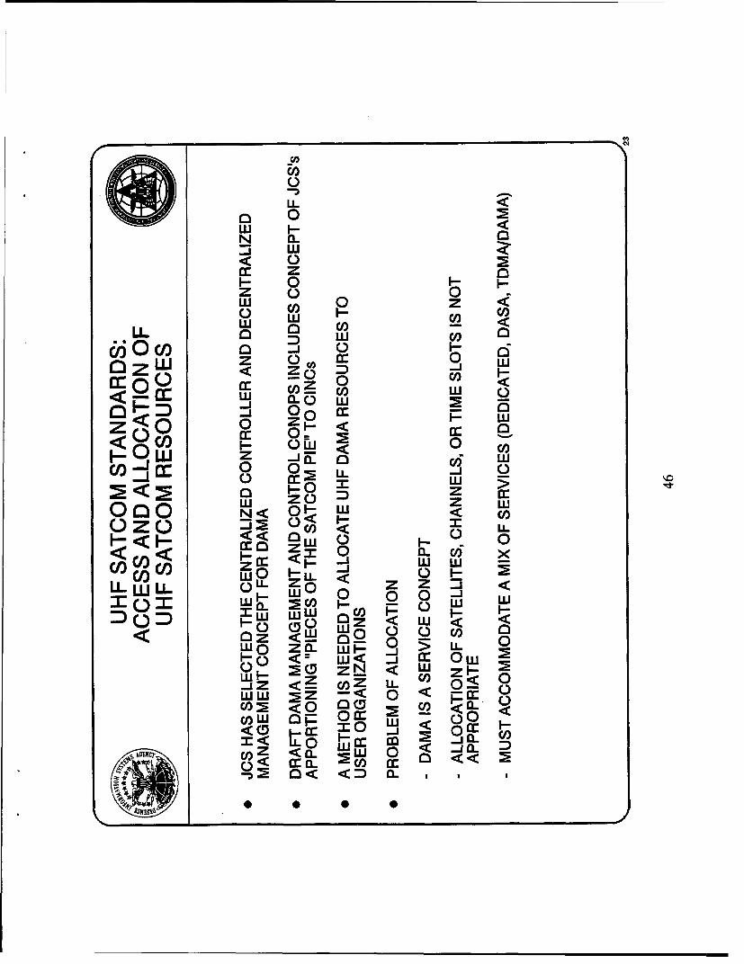
DEFENSE INFORMATION SYSTEMS AGENCYJOINT INTEROPERABILITY AND ENGINEERING
ORGANIZATION (JIEO)FORT MONMOUTH, NEW JERSEY 07703-5613
TUTORIAL ON
SET-UP AND COMMUNICATIONS DELAYS
FOR ALL
UHF SATCOM DAMA MODES OF OPERATION
• •• JIEO REPORT
O'9120 NN 1994V
~~TUTORIAL ON
1/21/98
Defense Information CenterATTN: Pat Mawby8725 John J. Kingman RoadSuite 0944Ft. Belvoir, VA 22060-2618
Reference our 01/20/98 telephone discussion. The tworequested publications are attached: Assessment of Optionsfor Improving the 5-kHz UHF DAMA Waveform, 10 May 95; andTutorial on Set-up and Communications Delays for All UHFSATCOM DAMA Modes of Operation, 20 Jun 94. The author (A.Pappas) places no restrictions o- the distribution -f thesepublications.
If I can be of further help, let me know.
4ýBob Hager
*/
FOREWORD
This briefing and tutorial have been prepared by the Joint
Interoperability and Engineering Organization (JIEO), whose
principal interest is to improve joint interoperability among
command, control, communications, and intelligence (C3M) systems.
JIEO prepared the tutorial in response to a Joint Staff direction
to provide a fundamental discussion of principles, capabilities,
and limitations of the voice services supported by ultra high
frequency (UHF) demand-assigned multiple access (DAMA) systems.
The user community's understanding of these areas will enable
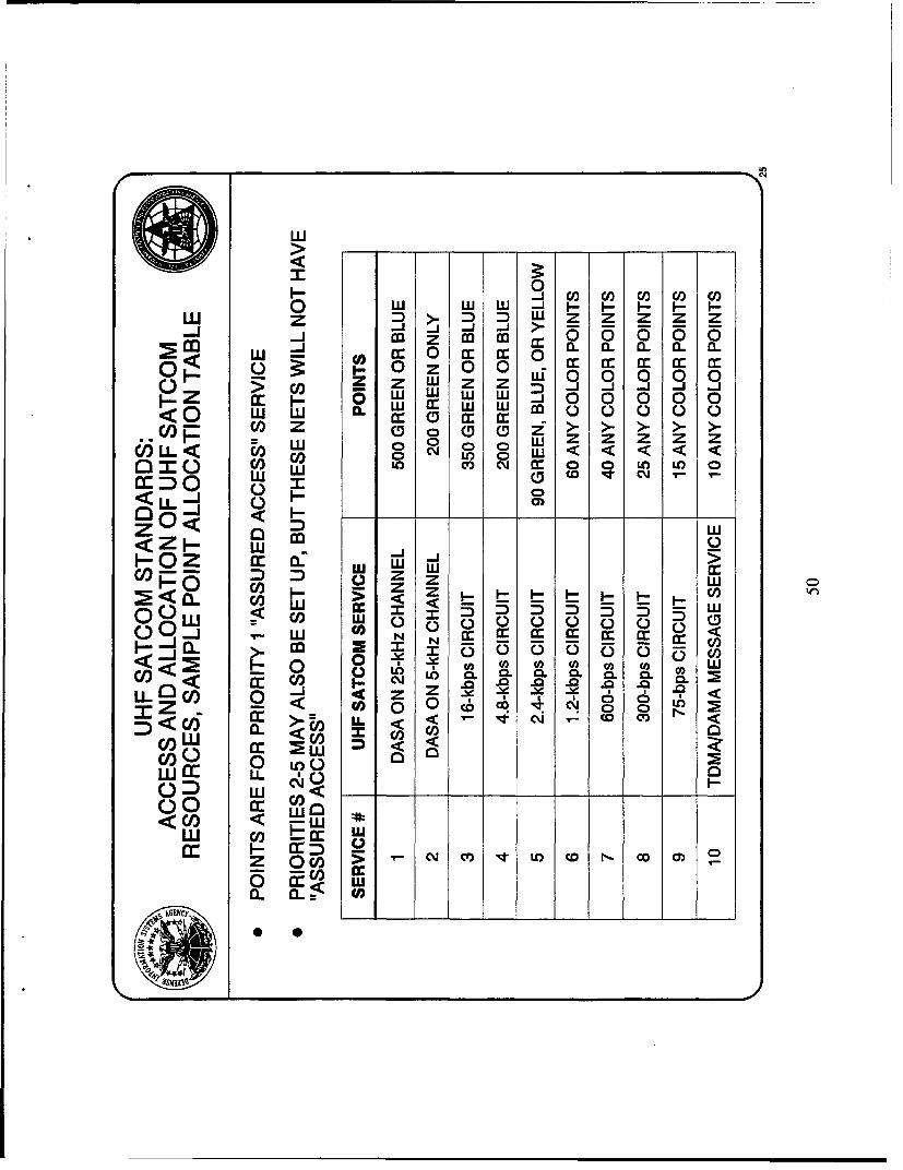
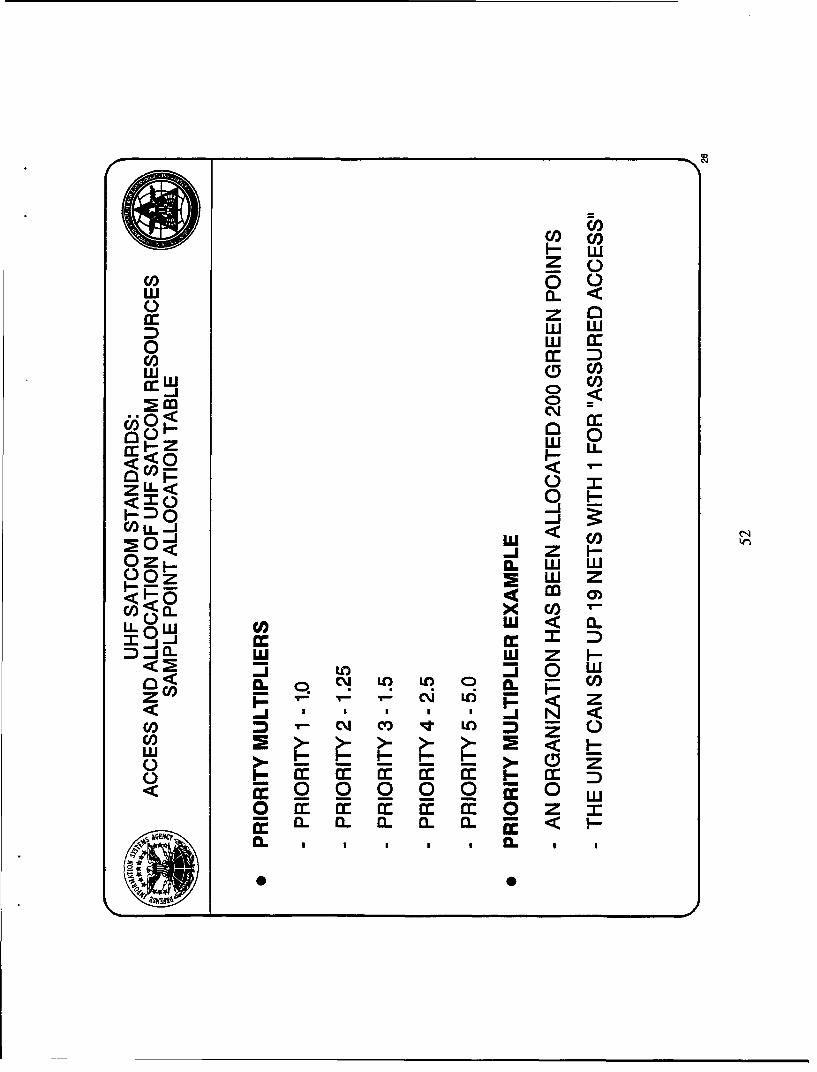
active participation in the definition of the DAMA management and
control system. The briefing and tutorial were prepared by
Andreas Pappas, Defense Information Systems Agency, Joint
Interoperability and Enginneering Organization (JIEO), Fort
Monmouth, New Jersey 07703-5613, Jim French, and Frank Grausso,
LOGICON, 145 Wycroff Rd., Suite 301, Eatontown, NJ 07703-1842.
FOR THE DIRECTOR:
LOU iSJý PILLA
Deputy Director, for Information
Transfer
zz
0T
U3
a) oz
~ 008
cz o
CIS Q ~ ~ O
U, ~ ) 'n
v H Z -
~ W2
00
r
coo
m00
z E 0 0 ce)c~IL T- 0
C00 CO z [- -.
a: z w IL ce) cj0L L)z LLOi
U- < F-0<-I
LL CM - 2fJ. %.
o z wl
w 0.M 0 o
Cl)L U..W
CO Co
cz-
4- 4)
F- 0 00 ) 0
co ci
E0. ~C E-L)c
cz 0
o '-o 0
u Cu
C) Cu
-E z
Cutu
LL4
co 0
>-z
CO, C/) 00 Co Z
w 0(L J
<~ ~ < .w/z CCW
>- z u
C)0 a: Oc C/)00C') C/) Z 0
COw D U- Z <0
>, 0> 0 2 <U
rni < W W X:0 cai a: cr <
W0 S S
00 o
4)ct C) .CczU4
0 0 ~ ~ 0 U 4
4)4 CU 0 <
_n 00 >2 0
U, *S. CD. cts. .2 o
vW 0H0 cz S.~
CU -n (1) M) U, 0 CU0 (D
40 3 4)
CU~~; 00 Ca4 U O C
w) .2J 00 ~
- CU CUCA U C
zo ca o2 ).caC 0 C
*0 - _ C CU :2 U ~ U
4) - - 4)4)le
4) 0CU) U C
4) CAUC - U ~ .
2H = U o2
4) U, ) U, U
e n u 2i-2 2 - U cz
~---~ 4) 0as_ -
~ U C4
4)4 rz-~ -
2 o W4) Uz 0 0 42 U
Q, 0
00 asU
o ~ ~ ~ ~ ~ ~ b =~~C U 4 U ~ C U >
CUr U- C
CU 4)4U2
2 0w ow~b) , C
4) 0
0* 4 0a .24) )
o td - * -
4 . 0t 0 CIO CU 0<
CD 0~ *0 5 O .I CU U 4
0) <w 0 Uz- w
ccrw o P*.LLw D OH<H-z> 00
CD O 00W~ W. 0 c-
CO w CC 00ZClO 0 z
H> 02DCl) ZO0COI jn
<0 CO wo~~ W ccwCo
<o M.;: W < COZD
CO~ -H H/ 00 C3
20 >.)< H LLDC F-0(Co -L /)<L
WZ COW><LUL0<
mH a-M LI M
0l O rL
C4.
U C-0
LZ 0
co CIO-
Q cz d) m-w4 Go; - 4-Co 2 * CUE
W3 ~ )~) . - .
CdUm. 44
-. I
ed -d C4~
CU CD
4&0 0I L 0 . ~ ~ C
C). E W3U 2 -
.E 0Z E p. 0 Q2
U- CU0~ C d~
mU 0 0
COD 4-
UC' .0~ ~ C
oo 0
000
*-n &n 2 -44-
_ - C > C
I- W
LL C')
<U 00L
0 0<z C. z
ZZ HL0 DC)ca: _u 0 0
o- o CD
0 0 < I-wa00 D Zn CCn W0w 1
0 c M~ 0 L w 0= a:CO) 0 C/)z -j l z 0 -
Lo <ci 0,00O T- za 0
LL 0 0a 0 LLQ~. wDz wj~ H W 0
H < 2 OJ 0 0-a:~w
z cc 0i w fw a: C- < 0.O
z 0
20 00
U22
C) 0 14
d)
00 0~C
c~ 0 .0 8C
04 C) 0.
o U > ~ . 4CC C.- cn
co; ca 0..) C
0) W~0 .
u0 Cd C)cc 040
4) d4) U)
&w 0
o Q"cc d) w 'U
4Z t'44)
-~ <
C) 54 C) '4- 9 ,dCA d4 0
W , 4) '0 '4-C d) c-- W
0 ~~~ am$ ' ) )44-) *d &) iU
41.0 04 CA4-4)('4 4) 4) -0.~ .
w- 0
4)) '.4 -d 0- 4 ,4
00 ) 0 C < 0 0
4) U, - o)0 0 0 4
U a)
4) 0 4.,
'4- ' 4) Q4
d4 40.
'- 04
ul 1- .; 4) 4) 404)d C
-U 0-
La
w
-J 0
z a:FD
LI- () 0 w1o 20 0 0
CO) wn L 0 cca: cro z
<Co < 00
ILJ CC C/) mi)
<- 0 o< OO)
1--Z OH 0-- < w z)
0 EE I -r -) < /C0< - L L= w < W N
i -J
~W 0 5-aZW.cc a. M < z 00< I-
CO ~~ <O co W0-a n a-wcc oFc 0 z z5
UL> F- 1 < 2
z <W z w ~ <wo ZZ z <
w 0 aw w ww( 00 m a 0 00 Da
z < 0 z zOz z S
4,))
0 -, c i>u C 0 4)
4))
4) 0 CZ4:-= .- 4
-z 4)
Cu 4 4 C
co .0 00u
42 .0
0 Cu C"4) 4)
cfs 00,.~C
0 _ c
Oz 0 - CuU
a)4)
t- 4)d
C) C
0 0
64~E. cd
o 0 E
cuz
oz - bor-0
4) W3 CIS m--
cz W 4)4~C
= 0 4)E
0 m -q .- -0 ~UU 0u ~ CuOC
Cu 2 - ~ U,
COC
0 z
Z-J 0 WL
Ca oL z0 C/)-0 0
<z0
co ~~ WW/)zLL c/) C/D ~Z (/3W z
0 CC/) WLL C/3W
zC/3 wi 0J /Wus< I C) L-
o< L a-~-1 -
hGEN ~W < -C) Wa< cc FD
C's50 0
0I
0O 0O0
.- .0
C- *U - d
Cd 03 U, P
- d 0 04.
-Q 0 -n
Cd- c
Uu0U
a) UEU U
2.5 U,
U, *= ~Cd ~
_0 E o0> 0.0.. 0 *~ .
0 $. . CO)U
o ~ u C6U' U0~ Wj c' ;
W2.)~ ) ;
z0 zDoJ E
-i z
mzt
zE ii.
< iiU L
< D 0
Lr/z Z OM- cji /)O
0 (WC#2WW- /3 L)-LCC ) CU 4.z
F- :WU 0 E- 00< D y
z E (D
D~ (DOM0*o EE_/_ 0a
o LL LL (D
-2.--
1-. >0ý
0
Cd C.) co
C-) c). '
- -CdCd
-n CC_
0 00
cd) 0 )4) a) c
-0 0 _2 2 0 . 0 03
Cd~
c0 0 +a)oW
0~ 0
0 0z c'Ro 0
2 Cd~~~ 2Ua) )
cn -o (1 d
2: a) _z U, 40 .0*
0 )
0 0 4. 6- _ 0 U, =
0 c
0 cz -0* ~ 4
C:6 4-C * - as 0O) C6 ;.. >
Sa) C4)
Gn C: -- ~u' .
o2 L) = -d U.
0 cz~- ~2Aa. 0 7 .2
oz
0D M
C,) I- Er0) WO WI-
00C~~zO C.L wc
o~ -J
Iw. cc <50 (L WRM
(L o- Z coa
oF W
M--
0 C/) a.z: 4
4:W
~4- -
*0
0
0
CO >~
0 0 0
cn
cz
2Z ýr4-
0j
CO R)
0~ ZZ
0 Qj< ZLUZ OJ0LL z
C/) LUcZc C//0)0
COLC z/O
<C w >
z
Z LU
wU CO) L
Z W W C/)-Jo a mcc C/o WCo <LU LUJ Z(0 COI m Z< 0-<
Co ~ <z O z <
- LU
co
C4 ucz 0
0 cz~
00.C ~ .
0 c. . .' .
cz u~.;; m = ~ =.
>~ -n
cz E Ep- ~ ~ -
- -Z - u0 oEu 0 E t)o0~ ~ >~
u- Z u = * - .
0 _ 0 - Cu 0 to
to - .2
*~ ~~~ U ~0 0 0 C
w 0- coo
c i § -- c c
mr- 0
c. E
E 0 E c
Cl?)
C/O
LW 0 0
SzO-JC/ Zulo *a*
<CO)Z ri n.. wo oO z-%Vi..- 0.
Z m 0
oL Z I
II0 z
0 CL 2 F- 0-
(.)~o U) 0 () ,A 4
Co Lu co Lw
<l <HcrCo QW Z<
< C/ 0D
w. -O T
oor. 0
02
rdA
0
00
l 030
0d U
cn
* U, 0 um)
OW< LWQ-J< O0 w j i
0< ZOu
ZW 5;w
0i. Li O 1
< - <w
M i)w C/)0 Cwc W L
< ~H< 2 F-o/) oz Cl
H < fr<
* U W LLWC
LTI-
1.0.
10 0 0
9z 0 0. -E
0 E ~E
- z -
En
E z -
'.0U
-5 U. 2-00 E U0C
C-) EE E 2) EU
0- Q,
u coQ, -z 4
Lir_ c
00
LLI
0 cr0
M 0
0
0 CO 0
Z-J a/ -
< 0.zC) 0c
7o Oi'- 1
0 < 0"0O- <2 0 o
<~ < -1o OM C/
0- Z
(L) C40
1.0
CA-
0 C4 - l-~ ~
~) 0 0 0-o o
oz to o
0 0z m ct 0~4-4
q0 m
co 0 -0
oc
00 4
0.- 0
00
C14 ~ -
wj LU0 z .0z z g
0 .ccc-w C/) (.) -
C/3O
-J 0 88co COW0 /
cc < 0 000_ 0 000
F- w c1C/) _ - F c OL
0~~ cc 11a c cc
6/ -j cc 0 00>~ 0 ca LULLLLL
C j WJ cCO* I* w V)Li
0
> C'4
. 00
4) U.) _
U.)0 -U
.- C4~
U.)>,
_ COD
zU)
W2 -C03
wzz
ow
W LLw C/W Lw
0l 0 0 0
.--.- 0
< Z CU
0 000 0
1-3 0 000
0 WliLoLorrOk 04 4
Z< ZLC)~~ 0 0
o toC) C) 4
003
vi~ w
~ 0 .4-. C4-.C) ~ 0
C)l
.z
C)s 4) o
CCI
LU) F -
X
W LL.
ozw
IwCO CO COCO<
LU 0z 0 ccoF-Z 0II 0<0cr.,) az W C
00 0 0 0 c<0 n 0 :0:00 000
F- C zD P ~ w -- 0 r-CC I:-0MOL z O c zzw )L:L ,) rc ~
CM) cmw NWm:>) f2CC/ (.) < CMC
OW CM ~ C6o
0 ~WL. W 0 000 0
z~ <H - 0WWLiJ w 0-L:U.L
w W
010.0~ 0
> 0
-C-
40. 0 0 -0 -o0 a
>
oz to q
.0 0ý b O1. . 2
0 t-S
Q, 0 Z 4.
u a) -0 2
0*- W rn 0..0
2t 4- Z , ~ ~ , -U
0 -0 0=
- 40 . 0
H ~ a) .. tu asU,~
0 0A
c) 40. 0 C a 1. 40
'0 * d ý 0
cc c
_ Z 0
cc 0 0
- 0~ 0
) 0 0 0 CI
C-) 0
A
E' 42) .0a ~ .
a) cd bOe - Ira 0
2 )0 Z 0 0 b
00I- w /
wOOF _ Uc F cC
-j m- CO w C' cc
0o
F- COC0 0)ww 0~00
o0 CM i LO LOnE
-iC) 0 -j
0 LLLZ cc
W0 CO) -__0_0_0_0
F-~' m~ Z: 2 LL L
<O wco w.i
5F-0 03
W) 0 Cd0
00 .0P E~~
0
0 =o. -0 =C.0 - 0 P. 4. 0d a
.0 cd
C4CU
-C) C.) 4
0. mN US
E - (5 -
M.2 U0 0 0
CU 04 0) u~N
0-4 = 1) N L
>CU 0 U,
CU d)(U c0 0 1.
0o
.0 en0 0 0<
L). , > a 0 q
conC ) C,3-r On.
CA.0 . U ..0~o It
~~C N. U.U. ~CS 04
0 CU-;;* > 0
02 U W) 12) =01U) 121~~
> ~ 0
0m 0 0 N2 r E CUit Q.=
_C4 W)0. >
W2 (U (4-00 .0 CU I 2
0d 40 0 0 0 C 2 0
40. - 0. 0c~0
(1) S2) 12 z .t> > z t rS ~) 12.- ~ 0. 0 ~0 12
.~ 0.1) 0 0 N u ''C 2ew N
0
W Z
z zI- w0 WI
Z Zr Z ZN
<Cc C~J CMW cm N N~ NN<oU < <
(1) <~ V2 ) 0n0 0
WW 0o
HO -j .0- ~ -
COZ<a m' - cJ ~C CLJ CL CL
-O Z N< N N N ý "e
< CCo M I-C ) < 0
F22<mI wL
w;icC/)< L N N 0
U) 0
4) ý
4)~a)
-z
Cd CIO4
r . 4 ) 04
CUn CU ;
C.a On
CU U,*~ >
4) ro! 03U,
9zE -
it St.2 ,
o '0 CU
I- C0 CO) C -j -j
F -~ z zLU 00
a. LUa Q
CO
Cj)Co
00 <0< b 0
w0J00 LI.
CO CwU a:-uj~ LU E
F- a. ZC0 < Cz z 0
Co CLa~ F-E -L
CoW Z (aFL a ý- CE0 > Lua
CO 'Co uj 0 5 _ UL. LLF-Z CC LU~ C
<o~ a LU < w co M~ 0 IL a:u. _ F-
< 4cZ LL a. 0 -z Lu Lu W Lu U.z
LJF- z*--c0 0 I 3
-00
EnE
Cu o . 00
00
0 0C
.- al -0
0 cu C
Cu 11 W) ;:Nt
0 0 cz) d
0 -n
- 0 0 m 0tu Cu . Z -N 0
con 00 m~U
0 0 0 '~, ~ *- ~ N .*
IZ. .ctC
.- 2 -0 QC4 u
7; 0 r- 0 2 0
-0 m con e~
C.4 1. 0. -
2
0
C4
0 2 0 C
0 0 . 0 0.
Cl,
z -
w O 60 >- 0 COcc
crý-J
Co0C) Y. wo
DO Z ZK KK
M 0
Z ( i ~jCO)
00D _f C)I'*z) -j w w
LU rr) IL OZo > w L 0
LL~ a. wrzwor a
.3 m 0 4 N N NN-l) urn Id IU -YI -
I-coO0O > L O I OLCL n O..cL N
< 0U
0 -~4)b.0
*z 0 4) r. -
"a C.)
i.~CL 0 0to 6
oz CuL) t. *0
L) Wu6~. ) C4W EU "a~- ~ C
u0 o 0 cz .0
42 (L !:) 1CU2 o
I.--4F.. U
42' u0 > (
0 4) g, O.64)d) L)Q-D < C
~~~ 4) C 0
425 2 Cu4 o~>
ell cu 0. 0 to
4 -~ 4) 0 0 =
Cu 0 Q l
4) (u $. cu ~Cu.2 42 -0~2
4) 4 >Cu u 0 t-) F-
C* 0 Mu CZ 4) 0.-Cu Q 0z 0 6. U ) 42
0z 0 c
0 U) 40- -U4.
4) t4-* Cu 0C
.0 0 CZ (
-Nd m w ~ 0 - 0 -
=- 4).- Cu =- L.- 4
-0 4u 4) 4) 4) 0)
40. A) &0 w a ý
0
0
w -J
CO WO lC0 zO coD00 w 0 zo
0(00 < OW /
z0 z6COc
W< Ct) ioz -.
F-0 0i Nc
0< Zu < (A i0LJ C -J W Go~ N
0 co 0 W0CV
C/ 0. - 00za. ME 0Na
z C)) Ct
0 w 0 wC) - L IL cc CCJ
mJ ii iCO 4t
UJ W Lo 0
4)A
cn 04) 0 cn
=) w) t) .
U) .2 .4- 4= 4) .0N(1) -0 .z. = a
1.. w . Q .-0
a) 4) U
o o- C
C4 0 4) U 0 "a ) )~0 )
4)4 c z0
m0 0W2 4)4
0 > 0
W to (U I-0ý 0 0: 0~-
< 4 ~ o ) . 00 C '0 0 .
cu 0. co -0 UbO~~ ~ U) --, ~2~'0 4
t-~ 04) 0- .0 U
'0 C) 0)_ ~ 1
>>0 U.. 0 0 >) .
9_ 0 '0
o~~ 2 0 >.- 4
0'-d ~.0 o OC)~ 0 CA
0- 0 1. 1 ) cz ) ~-. 0. 0 r.0I. cz >-' .0.. . .0~
U) .r
0~ ~ 0o 0 1-
W 4) Ud 0F -z C .
4.0 V- -0 4') 0 >0 4) r. =
0z 0) o
o4) Cori
C3 -0 0. _ ý
> _- a) ril r 0
Q >
0 4) 0 0 4) .. cz - '
U)) .) = )
-1 . -0 4)CA =) .E".2 -~ W. 0. 0 ~ .
0 2l EO 0 ' 0 . 0 4 ) 0
40 0
0 E 4
b&0 -7, 4) = 40
0U)0 . ~ 0 U 1. 140
.2= = U 0 ' .0 >-. U
0 >0
4 .0 0n n'~- 4 0 >,
00 E 40 UE U~~I. ) -
4)) 0 to 4) 0 .
) > 0 4) 4 0 0 m)
2 < 0-~>0 ~ )- .U U) ) 0 ... . ~ - ~ U) In
coo
Cj) 0
E
co 08
5 N
too-ci) C"
00000u
<Z D
1-0 IOLL*
LL ~ WNN_
LL w CM -.t
w~ C4
CO m0 ~--r
a:
ýGEW~r
6r
6 QM
(1 Stcoo - N
~ a)
0 ~ ~ ~ Cow
0 -n
9z
*- o~ r- c4 u ~ ~ .
U4, u ~ ~~*C4.
= uu 0_4 > rA
ri~~t Q 0mO~ U "
00 co 0 I
" C3 W-E " 0 .
C0, CO~Ca 0 t
l z z a0 0 0
0 o o0 o o a 0> CO w
Co CoCD
Co Co Co co co CO tz o 0 0) 0 0l zI
0Z z z z 0 0 0oU of 0 0 o 0 0 0w no0
cocoo Z C O Co) Co L CO Co CO 0W 00 0 0 0 0
cc wo 0 0c 0o 0 0 0
c' ccoC'
z z
>0 cr <0 < ~ < O 00 <50
IN aN FON CL N O WN W
00< ZW CL N 0=o~co:M
'T wV coc' .0* ML~ .10
<zo0 < ci < z z C zJ Z z 6 z0
0o 0 - z 0 004 0 0 C-4 7
ZX N N Nc
10 10) UL LO 050E5
0 a
0
00 C
(u ow
*a 0 ;: 0 E00 ca Cu 4) -aCw.
'o Cu 4)d
IV. ,-. =) C D
CI .2= M2 Q2 O 7- 1
C. , 0 44. -C) ~C .
C ~Ca
0 Cu o wrc 0
0l 0 CIS a) 40 _ 0 Q.6 cqsS ~
C.) C) *C C co~C4)4 .0e u *- 4
0 Cu
0 0cc>0 06 =0 a D.4) 4
C) CA)
C) '.= 4) -. 4l~
CUd 4)4 2 u6
4) a- < (U 4
Cu CISc
N-4. E' 0 *=
o kn< ;
w CU,
LL. ba w 4.~ ) ~CU 0 C 0. IV) 0 . E 4 ' 4
xC C
40 0 ) 'A as 0
C~bCu
1. cc C .
40. >. 4 0 Cd~ 0
C.C
C ~ ~ ~ ~ ~ 4 .' . ) 'C -S-~ ) C
09 L. 0) 4) ID 0U 4) .E
cu 4 4) Cu E 0
C-4 0 0~0~*0ad ~ C C ~ ~ C C4""a 0 0 - a. u 0
C --- = 0 0 0 U
~ u C . z 00 - Z
- 2 V C u U 0 ~ >
'A Q) 0 .2) 0 En 29
LLJ
o0N0
-J wcc zz Q
w~ _/ C/)w <o
0o 0 co Q0Z~0~ 0j z a 0 H<~ Z D
T- 0 C)cc0w CO) CO
<-w a. w
H ) w <0 CO)0Uz -i E w
C/)i 8J 1=. 0J 0C0 L
w zz w000 N< OHF W < CO)
F- < - cco a- Co _
cri~~ w
L.L Uj U w 0Q 00C)-jD0 W~ W w
OZ co-0 0 0 Co) 0~3 < w cc o
20 Z W z H-wo~ w~ z8
om o00 u < a.C
< 0 = 0 <3x
a.) mU
CA C.
.- con
1- CU 4-
C4..
0o 0. u un)~
0 CU
cl a)~ D 10) 0 C2 >
U -0 0) u~ _
- U CU na
C4.) 0 ~ co N4 ol N
ci M VU~ 0 l .)Cu 0 0" A ,
CU u ~ c C C
0 0 CUo- 0
r0 0z -5 C -.
CZU CU0
Q -0o-~ . OC 0 CUC.)
CUdC) 0. . CI) C. CU
0Z .0Z
4. 0 0
00* C4
00 0-
CU cd~ 2 ~ _
cll
ww
> 0
0 0 ' 0
w .z Co
z z
L > z Ca:~ M 0_
0 w < - w CO 0>- ~ _ CL < l C 0
w/ U= a.w 0wC/3H Z. Cl
Cll) 0 W0 50x
mo<~ 0 0 0 =t
L)HCO a. F H>- 0
_ 0: c) a. 0 z Hco ~ < <coW< H 1.H 0 H < a.
z /) ZH1. 0 M 5. C):c8 0 w Zor W LL W <0QMj 0 CHý 0 0 Z x 0
Cz HWww B~0 HW / 0 f-~ 00 t -e- - <
PH- wz0 wW w< a: LL 0o COL HW- <3 < l 00W J H0 zI:) LL < 0 .-
C/i 00 -J: 0 < W(«L <0 WQ< < 0 0Lw w< oCl) 0L .
< 0. 00
0 4-WD
cU2 0 0
cz 0_ 0 0
On .cl~~~ ct 0
I-d W30 O~U 0
.0 0 Con 4) .
.0 0 a "a0 00 0. 0o0
~ 0 0
0 H: E-0> 0 c -
0 U,
E-4- 0 -cn U
- 0 0n0 - U0 C0n ci 0 co
~u -l 0 0
r2 0 0 0 0n0 C = it
-0 a) u ~ 0z a).
U,4C
M~ 0 0 4
E- a) *2 cz
CI 0 a)~0 ~ 4 41
0 ccU nU S-
40 0 "a
~0 0 I nII
Z 4-
(=) I. 0 U, cc 0
0-4 p~ ---
U,0 C40
~ -~0 0
z 0z 00
0 ~ U, U,
W3 0
0 -= C)
C:6 CZ 0U, #U,~~4 0 00 C
cz .- 2 004
0 - Q. 0~U 0 0
U, ~ ~ C' 0se U . 0 o
F- -J Ct) w Cl) C CO)0 wU wL w -J -I i -i
wz z z z z z
0 § 0 o. z. o. o~a> j) Z Z W Z Z D - ~- J-
z m - o w Ww W o oo o
<0 w LU D. w W W 0 0000
U- V) CO 0 C- O 0 W < < < < <
D- 00
0 w1<F
< z wF- w 0 c c W IIJ >
0 0 (W N N F- F-
OC) ~ Izowo0 CCO:m:LL o W 00 0 0 0 0o .) (.) Mo a
00 o Y V 0 ) C-) coWcn~i zO Lo rL CL CL CLc
CC Q0 0 M M 0 0. rL
00 co 0 0OR0c
Zl 0CO~> *1 O r.
C4
0) U4rj
a)z
a) con
ca C 0 >,
C) C) C) C)0~~ _z&! C D ý
73) a
Oc 0 0"
w rA
CIOu
0 Gn "
400
C4 0 0.C
~ C c a)
Enu
Cl, 00c
wa a.Dw
0 cc
00RF-W LL<H 0 cOH
Oz Lwz
< = -) = D
CO) LL
woo a: a: a: a:/ 0
() 0. a-CL CL ~<
< 0 qL l
C022
C. 0_-A ~CW 2*
a)C.
U, CAU
0 0z
C) CU
0~0j)
CU~( 4" ~ >
'00 CU4 0Hon;:CU ~ 0
U, ~ 0
'0 C5 0
On ~C 0 .0
U, 0 0
0~1 lz U U
o1 C. ' , .S~
w
0CO
ww
wo Z OI
0)I 0.F-F-F-Qz zo 0 ddý ý ZZ 0 Z HHF
C,) 00z 04 c~:1LL W Z= 0 -. OL CLQ
02c 11c0 O o0
CO>wýt > =,>2 0 a. Lu c~j (.5 L L(00,W0 O C.( ) CM W w
0 ~z LL 0 -- >>COZ Z 0 0 W w.oCl o w O W
co CO Uo) 1-.1 C/OQ
W Wcw LL M: ( .oILCL 0 z < z C
0~~I C4 Q/ 0 QI: a. / C OV a 0. a.
< I ý Y I M.
o
o _0Q
0 -
E-4 co
c o cQ.-
*o
--0i *0 cl
0~ 0000
-~ 0 0
+> 0 .- d
0 0* ýn 0
cts) 0
200 0
0- 0
0Cl)
C) CO)z
C/) 0LLU) LL c
cr : -J z
<, LL
'z co-
u~Q -J -L
0 0 C
< _j 0Cl) < 0 lor ----
LU-
rju .0 y2d
7E) ) Qo E
z Z 4) -IO
4)l =.-
Q 4) ,z0 cz
00
0d 4) 0 Q.NO
>
U, C-4)
a 4) a Co~l 0z 00 0
ocr CC 40 a)c z 4
.0 0 .0 0oo *-4 ý 0 W~
4) 4- cis~000 ý7 r) -
ol4.C 00
0z m 0u 0 0 )e 0
0 C 0 4) 4
U, to 0 = o - 0
w4 C. s 4 - CA
E U,
.oo *, o 4Us 0 bb 0cz cz ý E 60 d) 4)- r
4) ~ c * ) -. 0. ~- .0 )
SIn
0O 00
w LL.0 01 1
00 *
WILo
co I0 c)
0o~ 0
-J -- EE -
CO 10 0-~-
Z LL Ic
0
CO~F Z- 0000 0LU0
()0 'uo -
0 CO, _ 0
z z--
0/ OLLW 20.CC CL 0 U W
o~ LL.QO
~0 UJ-J _0 0 O ML u 0 C ý CT P I j WL0 0 00 O f
Lu~z Z MkLL L0 0 OO5
.0
0 0
o u-4 .
0 -
0.
as -0 0 CD
.0 0
0n -
0Z 0*
- 1.;
0.
0003~ a~ ~c
w0
zCOJ
C/) za: <
00CO Z z00 OO 0 0 0
LO z u cr) LO) u- ) c r
F-J
wzC) z
er= 0- Z a 0 000D 0 0DM~ < 0 .. WD 0 *00 a 0 C 0IL a. 04 io c' j 04*
OzO CM Z (5
-Jcr Cl 0_Q 0 00L
-- - <
<c' 1 r 0 u 4
DC ZF-ZCo <C/
% C3 2 Lz z a. <0
0) z<CDW 0 a Na- ~ ~ -< (a L wF
0~Ec 04 w0j 0 0 cc 0
NGECYw 0 -1 -j L LL 0 0
0 .
1 .0
.co.
In.a)b
co
~criu
o 0o F-
zc
cisi- ~0 "
U,3d e
w co,1Cl, ICI
wCo CO)
COF- Ci
zo >Cl,
I.- -CC-
WI 0 , I
0O L 0- :r a . .
Co 0 ol Cl 0.. j -- -
~ ~ Wo
Z L ll~
_o C U-
0z <= '
-0 LQ
z CLL <_W CO) O..oLw w w-
z z z zzzzzoZ000w0Lu
mZ- z -
)2~
.~~~C 00 u u
Cu 4u Cu
o~C 0 0. E o C
w u 04 Cu)-U) 0 0 in" 04
C= 0Cd, -a a)2
S'o cd CA -
4) )Cu
0.C
In4) 4) 0 .Cu U; t
4) Cu c
Wu d. ) Cu0 o 0 cis
7E. at Cu )
~~Cu(4 0 2U 5
0) CU E. ) .. ) C
U)U) C > Cu II- E Cu 04 4
rn- 0Cu0 "i~ C 4) cua C -
U7 Cu U2.0.
- U)Cu U) 0o6 )
Cu 0fl))
co >Cu-d
Cu CuC m2
0.
0u u Cuca C
E4 4)CV X U
Cu- Cu3
.. Cu
CuU -U-
z wUw WI- L
U_ 0H t=
w z <UP_C) 0t I- 06 < <>0rrJ <- < < -
z Z Z <
o o -LL 0a< -I-0. Io LL a-. N Z
C/o 0 I O) cc-~E= 0 Hr L- wW
LU0 cc O0 0 z m < -- z H
< L 0 CL 5Z L< <Rz
HZ Z F
D M LU << z<HL Z3
CO~ 0L 2L . < wZW0w Z a ~ cor QH0O-
Oz LL z _j
< z- Z ccc (3 V M 0(zc H L
< z ý_ Mz ZW
o 03 ý -<r L i -Z ) c c z
LL <0 0L CC 3:0
LL 0 F Z <OH
LL ~ a< z wW 00 ~Z j1.H 0 0 LCO
oU - 0 Dz Ow~
a. > 5:0 0 m<
Z< Z - < <a < Wz ~ <~. H-0 _a..
DEFENSE INFORMATION SYSTEMS AGENCYJOINT INTEROPERABILITY AND ENGINEERING
- ORGANIZATION (JIEO)FORT MONMOUTH, NEW JERSEY 07703-5613
TUTORIAL ON
SET-UP AND COMMUNICATIONS DELAYS
FOR ALL
UHIF SATCOM DAMA MODES OF OPERATION
JIEO REPORT20 JUNE 1994
TABLE OF CONTENTS
Paragraph Title Page
1 INTRODUCTION ................. ................... 11-1 Purpose .................... ..................... 11-2 Background ................. .................... 21-3 Applicability ................. .................. 41-4 Policy ..................... ...................... 41-5 Changes .................... ..................... 41-6 Report Organization ............. ............... 4
2 UHF DAMA SATCOM CONCEPTS, MODES, AND VOICESERVICES ........................... .......... 7
2-1 UHF SATCOM Time-Division Multiple Access ... ..... 92-2 Demand-Assigned Multiple Access .. ........ 132-3 UHF SATCOM TDMA/DAMA ......... .............. 152-4 UHF SATCOM DAMA Modes .... ............. 172-5 Definition of Voice Services Supported
by DAMA Standards .......... .............. 21
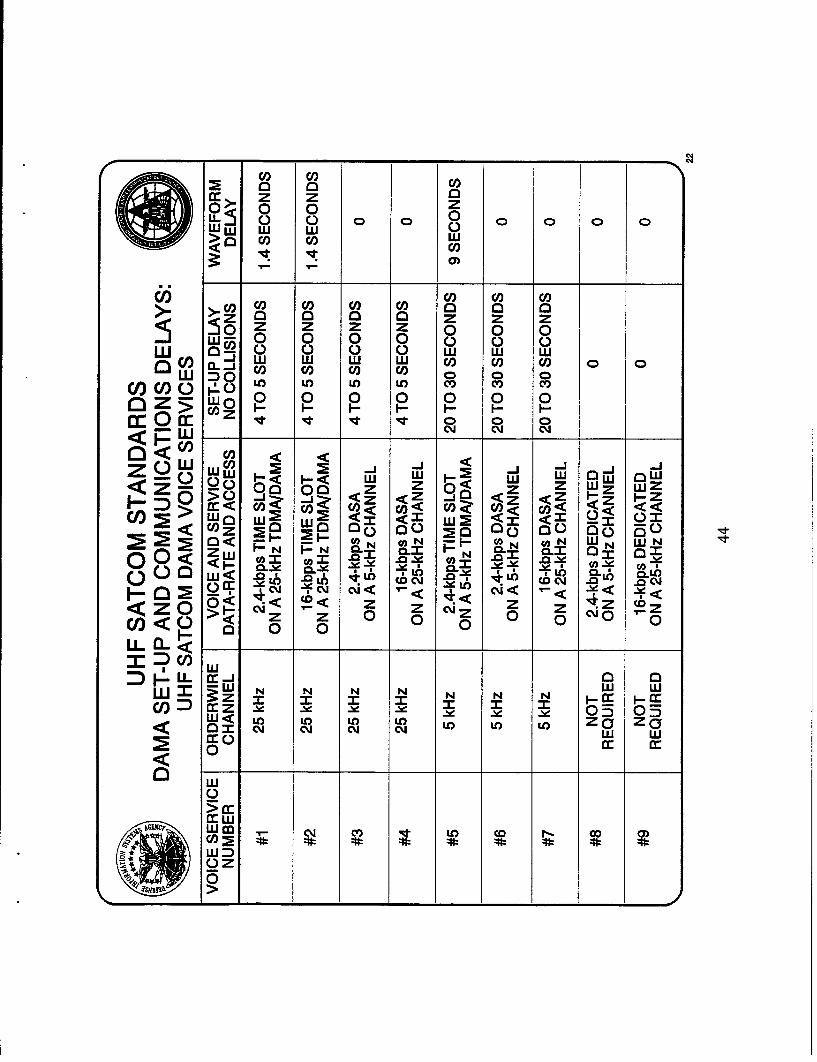
3 UHF DAMA SET-UP AND COMMUNICATIONS DELAYS . . . 253-1 Terminal Set-up Delays ....... ............. 253-2 Link Set-up Delays ......... ............... 333-3 Waveform Delays ............ ................ 403-4 Total Delays ............. .................. 40
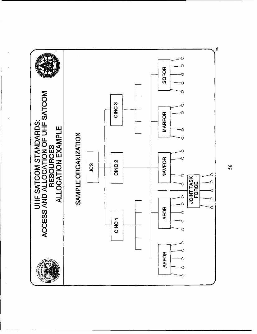
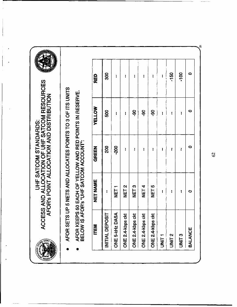
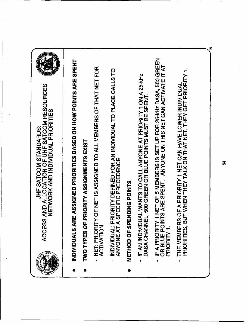
4 ACCESS AND ALLOCATION OF UHF SATCOM RESOURCES 434-1 Background ....... ................... ..... 434-2 Resource Allocation Problem ..... .......... 464-3 Proposed Point Allocation Concept .. ....... 484-4 Allocation Example ......... ............... 524-5 Network-Access Class of Service .. ........ 56
FIGURES
Figures Title Page
2-1 General TDMA Frame Format .......... ........... 102-2 Waveform Delay ........... ................. 112-3 Parking Space Example ........ ............. 122-4 UHF SATCOM TDMA/DAMA Concept ..... .......... 163-1 5-kHz Acquisition Delay ...... ............ 273-2 25-kHz Acquisition Delay ..... ............ 313-3 5-kHz Waveform Link Set-up Delay .. ........ .. 353-4 25-kHz Waveform Link Set-up Delay .. ....... 374-1 Centralized System Control and
Decentralized Management ..... ........... .. 444-2 JCS Apportionment of SATCOM "Pie" .. ....... 454-3 Sample Organization ......... .............. 52
iii
TABLE OF CONTENTS (Concluded)
TABLES
Table Title Page
3-1 Waveform Acquisition Delays with No Collisions 333-2 UHF DAMA Delays ............ ................ 424-1 Sample Point Allocation Table .... ......... 49A-1 Ranging Delays with Collisions ..... ......... .. A-4A-2 Login Delays with Collisions ..... .......... .. A-7A-3 Delay in Acquisition with Collisions .. ...... ..A-8B-1 Service Request Delays with Collisions ....... .. B-3B-2 25-kHz Call Set-up Delay ....... ............ .. B-5
APPENDIXES
Appendix Title Page
A DELAYS IN WAVEFORM ACQUISITIONWITH COLLISIONS .......... ............... A-I
A-1 Introduction ............. .................. A-1A-2 5-kHz Waveform Acquisition Delays
with Collisions .......... ............... A-2A-3 25-kHz Waveform Acquisition Delays
with Collisions .......... ............... A-7
B DELAYS IN SERVICE REQUEST RESPONSEWITH COLLISIONS .......... ............... B-I
B-1 Introduction ................................... B-1B-2 5-kHz Link Set-up Delays with Collisions . ... B-1B-3 25-kHz Link Set-up Delays ...... ........... B-4
C REFERENCES ................. ................... C-i
iv
CHAPTER 1
INTRODUCTION
1-1 PURPOSE
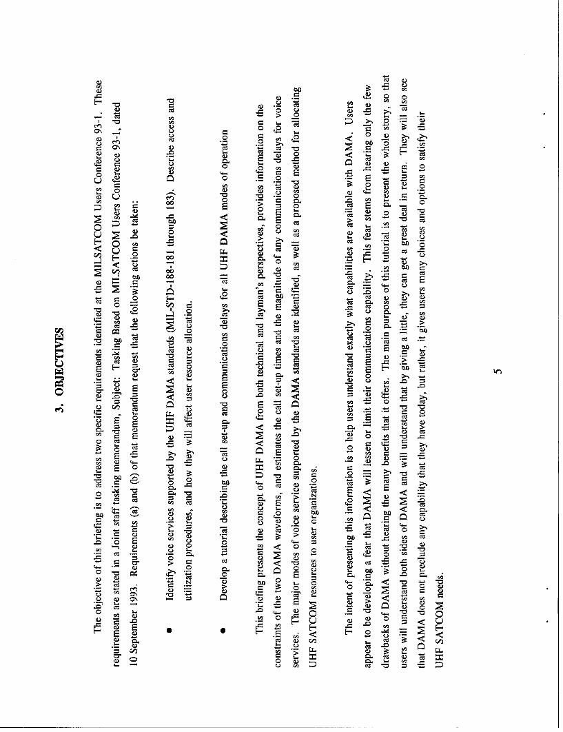
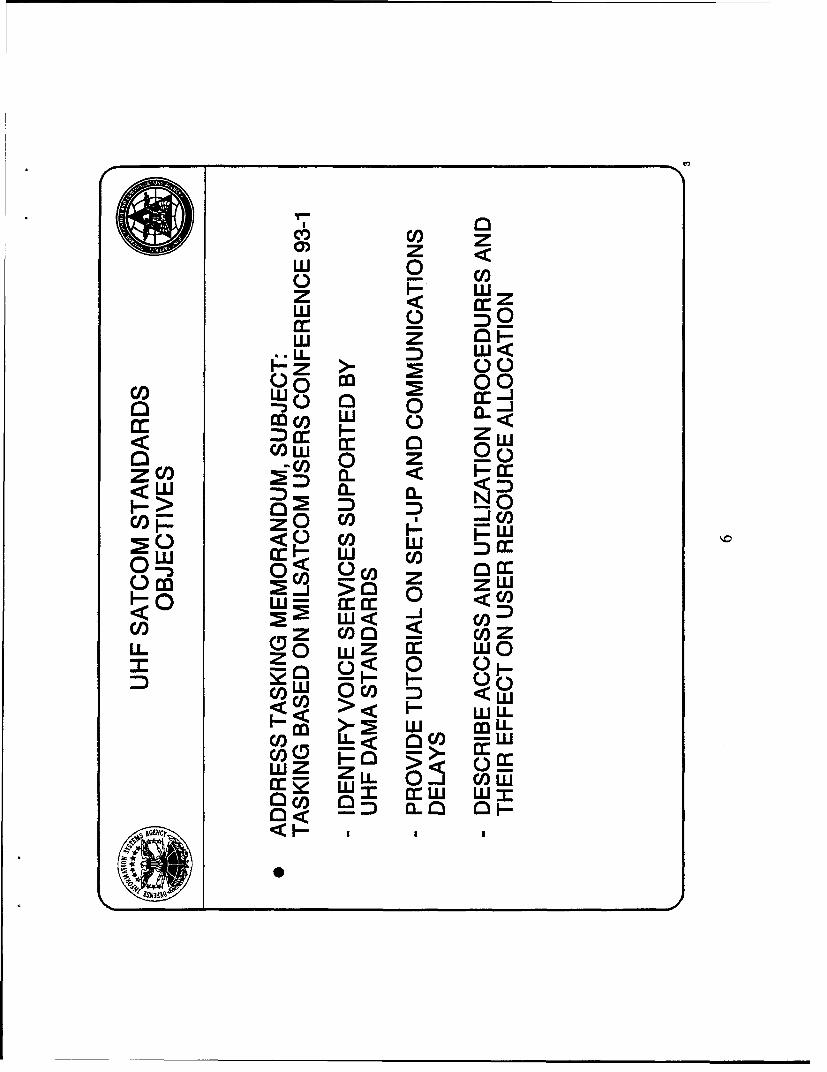
The purpose of this tutorial is to address two specific
requirements identified at the military satellite communications
(MILSATCOM) Users Conference 93-1. These requirements are stated
in a Joint Staff Tasking Memorandum [Ref. G], Subject: Tasking
Based on MILSATCOM Users Conference 93-1, dated 10 September
1993. Requirements (a) and (b) of that memorandum request that
the following actions be taken:
"* Identify voice services supported by the ultra high
frequency (UHF) demand-assigned multiple access (DAMA)
standards (MIL-STD-188-181 through -183). Describe
access and utilization procedures, and how they will
affect user resource allocation.
"* Develop a tutorial describing the call set-up and
communications delays for all UHF DAMA modes of
operation
This tutorial presents the concept of UHF DAMA from both
technical and layman's perspectives, provides information on the
constraints of the two DAMA waveforms, and estimates the call
set-up times and the magnitude of any communications delays for
voice services. The major modes of voice service supported by
the DAMA standards are identified, as well as a proposed method
for allocating UHF SATCOM resources to user organizations.
The intent of presenting this information is to help users
understand exactly what capabilities are available with DAMA.
Users appear to be developing a fear that DAMA will lessen or
limit their communications capability. This fear stems from
1
hearing only the few drawbacks of DAMA without hearing the many
benefits it offers. This tutorial will explain all the operating
modes that DAMA offers and will illustrate how users' needs can
be satisfied, as opposed to continuing with the current practice
of providing only a limited number of users with dedicated
service.
The DAMA system was developed by systems and design
engineers based on their understanding of users' needs. A great
deal of capabilities and flexibility have been designed into the
system, enabling it to meet the entire gamut of user
requirements. However, it is a universal truth that to get
something better, something must be given in return. Therefore,
a great increase in user capability and flexibility must be
traded for some inconveniences some of the time. The problem the
DAMA program is facing is that users are concentrating on the
small inconveniences (the down side), and have not been fully
informed of the full range of capabilities and flexibility that
will be afforded by the DAMA systems (the up side). The main
purpose of this tutorial is to present the whole story, so that
users will understand both sides of DAMA and will understand that
by giving a little, they can get a great deal in return. They
will also see that DAMA does not preclude any capability that
they have today, but, rather, it gives users many choices and
options to satisfy their UHF satellite communications (SATCOM)
needs.
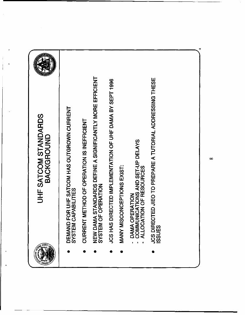
1-2 BACKGROUND
The relatively low operating frequency, low cost, ease of
use, and operational flexibility of UHF SATCOM make it the only
communications system (commercial or military) that can support
certain long-haul tactical, contingency, and covert military
operations. However, the UHF SATCOM constellation cannot
simultaneously satisfy all user demands for service reflected in
the MILSATCOM User Requirements Database. The current terminal
2
design restricts efficient use of the UHF SATCOM system. Current
access techniques are based on single net per transponder (SNPT)
and dedicated allocation. Studies indicate that this method
results in a limited number of user nets that can be supported by
the satellite resources, and it introduces significant
inefficiencies in channel use [Ref. E]. For example, when a
particular net assigned to a channel is not communicating,
channel capacity is wasted.
To overcome the severe shortage of UHF SATCOM channels and
this inefficient use, the new terminals will use DAMA techniques
in conjunction with time-division multiple access (TDMA) and
narrowband voice (2.4 kbps LPC-10). Two waveforms have been
defined, one for 5 kHz [Ref.B] and one for 25 kHz [Ref.C], to
provide user access on demand. Multiple users share a satellite
channel, and subscriber terminals send burst transmissions during
a fraction of time known as a TDMA time slot.
Realizing the benefits of DAMA, the Joint Chiefs of Staff
(JCS) has issued memorandum MJCS-36-89, requiring all Services to
transition to DAMA by the end of FY 96. As this transition point
approaches, organizations are asking for more information on the
new DAMA system and how its implementation is likely to affect
them. Several organizations have studied the implementation
standards and have become alarmed at projected call set-up times
and communications delays that can occur when operating in the
various DAMA modes. These concerns were voiced at the MILSATCOM
Users Conference 93-1 and in several official messages to the
JCS, which resulted in the issuance of a Joint Staff Tasking
Memorandum, dated 10 September 1993. This tutorial addresses
several of the actions directed in that memorandum relating to
set-up times, communications delays, and user resource
allocation.
3
1-3 APPLICABILITY
This tutorial applies to UHF SATCOM terminals operating
over 5-kHz and 25-kHz satellite transponders, in accordance with
UHF SATCOM standards [Refs. A, B, and C].
1-4 POLICY
This tutorial was prepared by JIEO, based on Joint Staff
direction. It will be used to help UHF SATCOM users understand
the operational and communications set-up delays inherent in the
current UHF SATCOM DAMA standards for 5- and 25-kHz satellite
channels.
1-5 CHANGES
Written recommendations or suggested changes to this
tutorial should be submitted to the
Joint Interoperability and
Engineering Organization
ATTN: TBBA (Andreas Pappas)
Fort Monmouth, New Jersey 07703-5513
1-6 REPORT ORGANIZATION
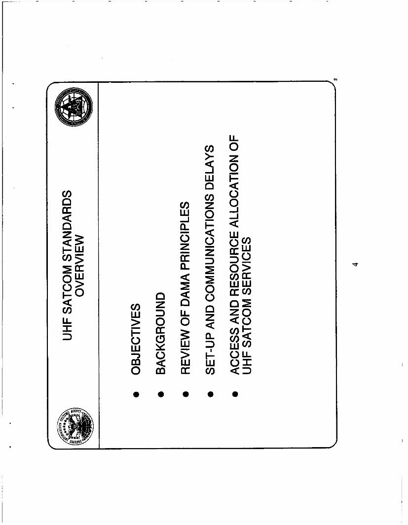
This tutorial is composed of four chapters that address the
following subject areas:
"* Chapter 1 - Introduction. Provides purpose,
background, references, applicability, policy, change
procedures, and report organization.
"* Chapter 2 - UHF DAMA SATCOM Concepts, Modes, and Voice
Services. Provides a discussion of UHF SATCOM DAMA
4
concepts and modes by using common non-technically
oriented examples, and defines the various voice
services supported by the DAMA standards.
* Chapter 3 - UHF DAMA Set-up and Communications Delays.
Presents the user with set-up and communications delays
for the defined voice services, and provides estimates
of the expected delays for terminal set-up, call
set-up, and waveform delays.
* Chapter 4 - Access and Allocation of SATCOM Resources.
Describes the access and utilization procedures and
their effects on user resource allocation.
5/6
(This page intentionally blank)
CHAPTER 2
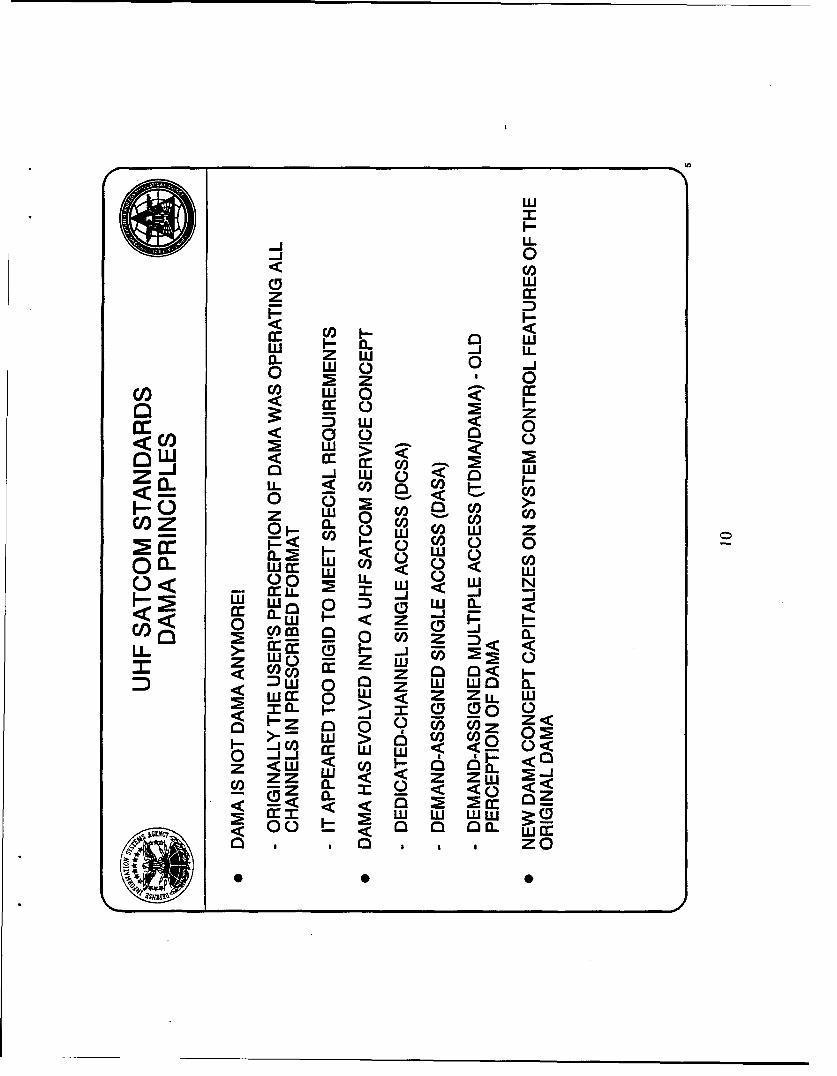
UHF DAMA SATCOM CONCEPTS, MODES, AND VOICE SERVICES
The purpose of this chapter is to provide a discussion of
UHF SATCOM concepts and modes supported by the DAMA standards,
using common everyday examples to which a non-technically
oriented user can relate. The various voice services provided by
the DAMA standards are also defined.
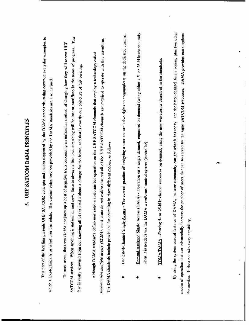
To most users, the term DAMA conjures up a host of negative
traits concerning an unfamiliar method of changing how they will
access UHF SATCOM services. When anything is unfamiliar and new,
there is always a fear that something will be lost or sacrificed
in the name of progress. This fear is really spawned from not
knowing all of the details about a change for the better, and
that is exactly the objective of this chapter.
Although the DAMA standards define new radio waveforms for
operation on the UHF SATCOM channels that employ a technology
called TDMA, most users do not realize that not all of the UHF
SATCOM channels are required to operate with this waveform. The
DAMA standards include provisions for operating in three
different modes, as follows:
0 Dedicated Channel Single Access - The current practice
of assigning a user net exclusive rights to communicate
on the dedicated channel.
0 Demand-Assigned Single Access (DASA) - Operation on a
single channel, requested on demand (using either a
5- or 25-kHz channel only when it is needed) via the
DAMA waveforms' control system (controller).
7
0 TDMA/DAMA - Sharing 5- or 25-kHz channel resources on
demand, using the new waveforms described in the
standards.
DAMA gives the user community what it has today: the
dedicated-channel single access, plus two other modes of
operation that can substantially increase the number of users
that can be served by the same SATCOM resources. Therefore, DAMA
has given more options for providing service, not taken away
capability. The following sections describe the theory of
operation in both technical and layman's terms of how UHF SATCOM
is envisioned to operate under the DAMA standards. This chapter
presents the following topics:
0 UHF SATCOM TDMA - Explains the concept of the new TDMA
radio waveforms defined in the DAMA standards, and how
many users are able to talk on the same channel
simultaneously.
• DAMA Concept - Explains the concept of users sharing a
pool of communications resources on demand, to allow a
greater number of users to have access to SATCOM
services.
"• TDMA/DAMA Concept -Explains how the new TDMA waveforms
implement DAMA for UHF SATCOM access.
"• DAMA Modes of Operation -Explains how DAMA supports
three different modes of operation simultaneously.
"• Voice Services Supported by the DAMA Standards -Lists
and explains the various voice services supported by
the DAMA standards.
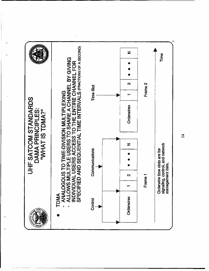
2-1 UHF SATCOM TIME-DIVISION MULTIPLE ACCESS
This section is divided into two parts to satisfy two
different audiences. The first part explains the TDMA concept
for those who have a more technical background and like to know a
few details about the system. The second part is for the user
who would like to understand the concept, but not get involved
with the engineering details. Both audiences should read both
sections, because a better understanding will be obtained from
seeing both a technical and a practical explanation.
A. Technical View of TDMA. TDMA, a communications
concept, permits many user nets to share a satellite channel. It
is analogous to time-division multiplexing, in which one
communications path is divided into time frames, which are
further divided into time slots where data from each individual
input is placed. With UHF satellite TDMA, each input can be
considered a user who has been assigned a time slot. Using this
multiple-access technique, a number of user terminals take turns
transmitting bursts of data through a common transponder during
their respective time slots. Thus, each earth terminal
transmission has sole use of the transponder bandwidth and power
during the duration of its time slot.
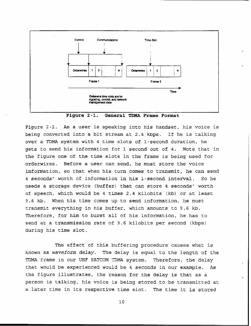
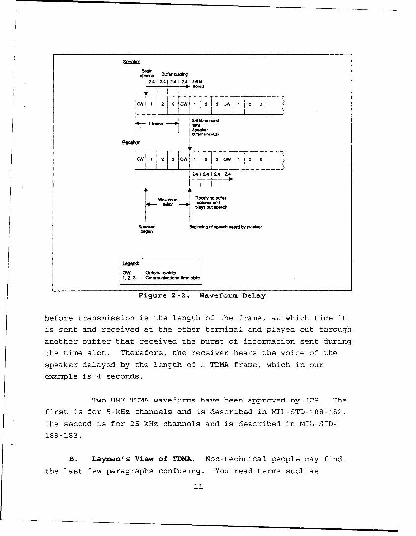
Figure 2-1 illustrates two frames of a TDMA system.
Two types of time slots are depicted. The first is the control
time slot, in which orderwires carry signaling, control, and
management information to control the system. The second is the
communications time slot, in which users burst their information
to communicate with other users.
Since a continuous stream of information (bits) does
not flow over the network, but rather bursts of information
during a time slot, to communicate over a TDMA system, a means to
store information between bursts is required. This storage
procedure is called buffering, and it works as illustrated in
9
Control Communications 'ime Slot
I 4IOrderwlres 1 2 N Orde Irs 1 2 N
Frame 1 Frame 2
Time
Orderwire time slots are forsignaling, control, and networkmanagement dafta
Figure 2-1. General TDMA Frame Format
Figure 2-2. As a user is speaking into his handset, his voice is
being converted into a bit stream at 2.4 kbps. If he is talking
over a TDMA system with 4 time slots of 1-second duration, he
gets to send his information for 1 second out of 4. Note that in
the figure one of the time slots in the frame is being used for
orderwires. Before a user can send, he must store the voice
information, so that when his turn comes to transmit, he can send
4 seconds' worth of information in his 1-second interval. So he
needs a storage device (buffer) that can store 4 seconds' worth
of speech, which would be 4 times 2.4 kilobits (kb) or at least
9.6 kb. When his time comes up to send information, he must
transmit everything in his buffer, which amounts to 9.6 kb.
Therefore, for him to burst all of his information, he has to
send at a transmission rate of 9.6 kilobits per second (kbps)
during his time slot.
The effect of this buffering procedure causes what is
known as waveform delay. The delay is equal to the length of the
TDMA frame in our UHF SATCOM TDMA system. Therefore, the delay
that would be experienced would be 4 seconds in our example. As
the figure illustrates, the reason for the delay is that as a
person is talking, his voice is being stored to be transmitted at
a later time in its respective time slot. The time it is stored
10
Beginspeech Buffer loading
2.4 2-42A4 2• 4 9.6 kb01stored
ow 1 2 3 ,ow 1 2 3 ow 1 2z 3
9.6 kbps burstI trarnesent
Speakerbutler unloads
[ziIII1I 21i3iOW 1 ý2 3 OW1 231 14 2.4 1 7-41 a 1
Waveform ReceiVing bufferdelay recwves and
plays out speech
Speaker Beginning of speech heard by receiverbegan
Lagend
OW Orderwire slots1, 2 3 Communications time slots
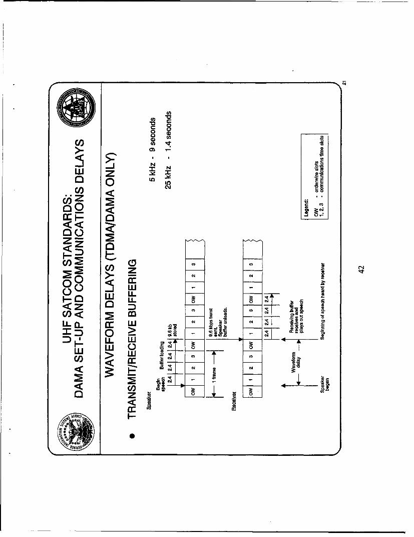
Figure 2-2. Waveform Delay
before transmission is the length of the frame, at which time it
is sent and received at the other terminal and played out through
another buffer that received the burst of information sent during
the time slot. Therefore, the receiver hears the voice of the
speaker delayed by the length of 1 TDMA frame, which in our
example is 4 seconds.
Two UHF TDMA waveforms have been approved by JCS. The
first is for 5-kHz channels and is described in MIL-STD-188-182.
The second is for 25-kHz channels and is described in MIL-STD-
188-183.
B. Layman's View of TDMA. Non-technical people may find
the last few paragraphs confusing. You read terms such as
11
multiplexing, frame, orderwire time slot, and communications time
slot, and you may have gotten lost after the first term. Let us
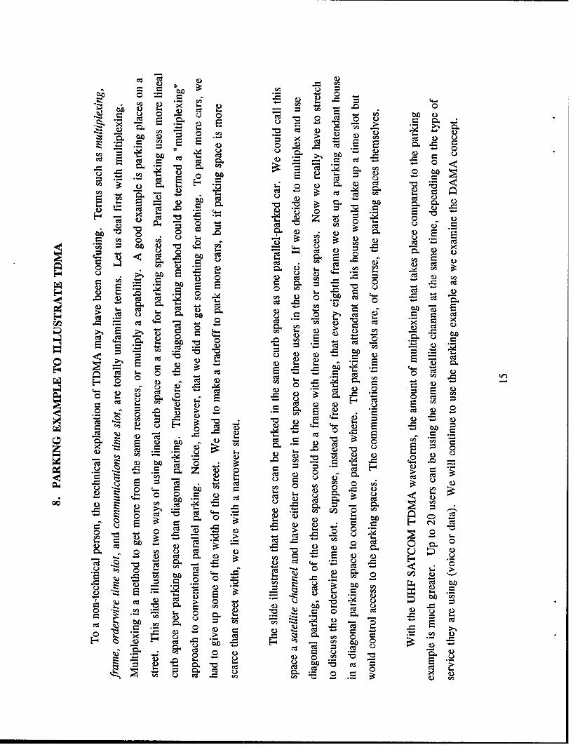
deal first with multiplexing. Multiplexing is a method to get
more from the same resources, or multiply a capability. A good
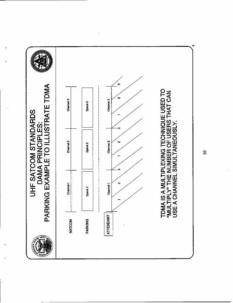
example is parking places on a street. Figure 2-3 illustrates
two ways of using lineal curb space on a street for
Parale Paridg
30fft 30 ft.4.. 30 ft.
12 3
Diagonal Parldg
Figure 2-3. Parking Space Example
providing parking spaces. Parallel parking uses more lineal curb
space per parking space than diagonal parking. Therefore, the
diagonal parking method could be termed a "multiplexing" approach
to conventional parallel parking. Notice, however, that we did
not get something for nothing. To park more cars, we had to give
up some of the width of the street. We had to make a tradeoff to
park more cars; but if parking space is more scarce than street
width, we live with a narrower street.
12
The figure illustrates that three cars can be parked in
the same spot as one parallel-parked car. We could call this
space a satellite channel and have either one user in the space
or three users in the space. If we decide to multiplex and use
diagonal parking, each of the three spaces could be a frame, with
three time slots or user spaces. Now we really have to stretch
to discuss the orderwire time slot. Suppose, instead of free
parking, that every eighth frame we set up a parking attendant
house in a diagonal parking space to control who parked where.
The parking attendant and his house would take up a time slot but
would control access to the parking spaces. The communications
time slots are, of course, the parking spaces themselves.
With UHF SATCOM TDMA waveforms, the amount of
multiplexing that takes place compared to the parking example is
much greater. Up to 20 users can use the same satellite channel
at the same time, depending on the type of service they are using
(voice or data). We will continue to use the parking example as
we examine the DAMA concept.
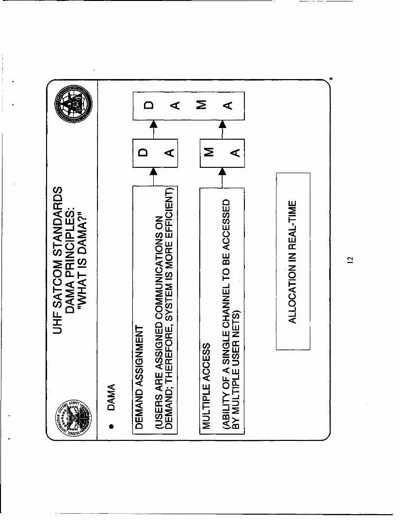
2-2 DEMAND-ASSIGNED MULTIPLE ACCESS
As with the previous section, DAMA is explained from both a
technical point of view and in layman's terms.
A. Technical View of DAMA. DAMA, a communications channel
access and resource allocation technique, provides the dynamic
sharing of one or more channels among many users or user
networks. Thousands of satellite terminals, within the same
satellite coverage area, may share the channels of one or more
satellites. Worldwide multi-user SATCOM connectivity can be
provided by using relay schemes between channels on adjacent
satellites of the DOD UHF SATCOM constellation.
The concept of DAMA is very simple. Given a pool of
resources that can be shared, such as UHF satellite channels, the
13
channels can be assigned for use on demand--thus, the term demand
assigned. Since many users are able to share or access the
channels, the system is said to have multiple access. Therefore,
the term DAMA means that multiple users can have access to a pool
of resources on demand, which translates in our case to UHF
SATCOM assigned to users on demand. Channel capacity is not
wasted when the particular net assigned to a channel is not
communicating.
Besides improving the efficiency of space resources,
DAMA provides efficient use of the terminal segment. DAMA
satellite terminals can participate in multiple networks, because
they can be designed with the ability to communicate on any of
the UHF MILSATCOM channels, both 5- and 25-kHz.
B. Layman's View of DAMA. Going back to our parking
example, and considering that a parking space is equivalent to a
UHF SATCOM channel that can be assigned to a communications net,
we can make some clear comparisons. In a pure demand-assigned
situation, when a person needs a parking space, he takes any one
that is available and uses it until he is finished, whereupon,
when he leaves, another person can park there. If we wanted to
authorize users to use spaces, we could require that a parking
permit or sticker be required, and have the parking attendant
check permits. Rather than giving a person a reserved parking
space, as when we give someone a dedicated channel for
communications, we would allow many people to share the spaces on
demand. In the case of a reserved spot when it is not being
used, it is wasted. If you have no reserved parking spot, and
you are looking for a place to park, you get upset when you see
empty reserved spaces and you cannot use any of them. UHF DAMA
can prevent this situation. Consider, if every parking spot were
reserved for a specific person in town, the number of people who
could park would be the finite number of parking places that
existed. If spaces were provided first-come, first-served (or
14
demand-assigned), the number of people who could park would be
many times the finite number of parking spaces available.
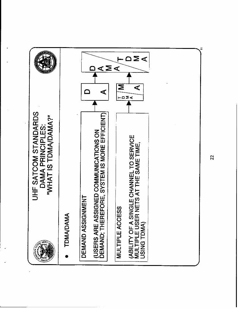
2-3 UHF SATCOM TDMA/DAMA
This section discusses the effects of combining the TDMA
multiplexing technique with demand assignment as it pertains to
UHF SATCOM. The concept described is for operation in the pure
DAMA mode, using the new DAMA waveforms and assigning
communications resources on demand. This concept is explained in
both technical and layman's terms.
A. Technical View of TDMA/DAMA. The concept of TDMA/DAMA
is also very simple. TDMA, or dividing the communications
channel into time slots, is used in conjunction with assigning
the time slots to users on demand, to allow them to communicate
over the system. This method, as it is applied to UHF satellite
systems, is illustrated in Figure 2-4. The figure illustrates
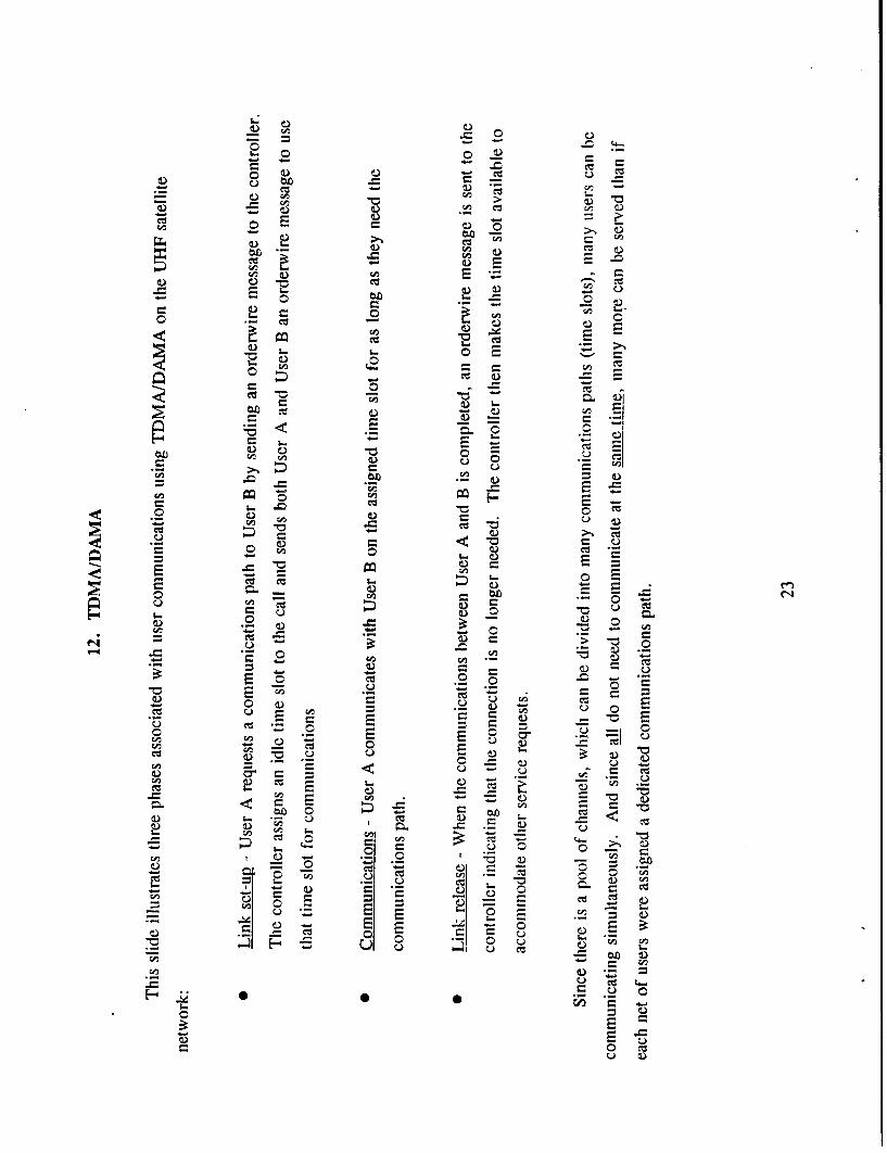
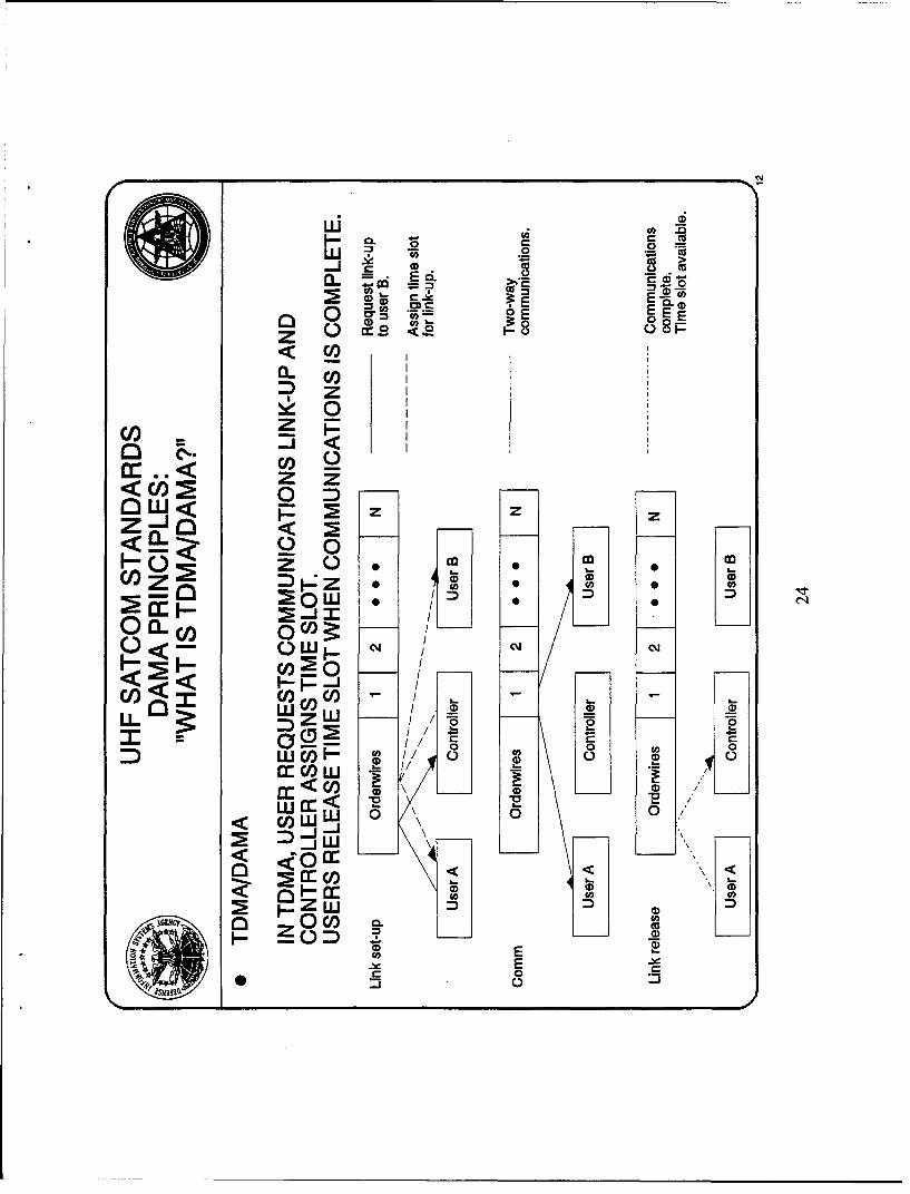
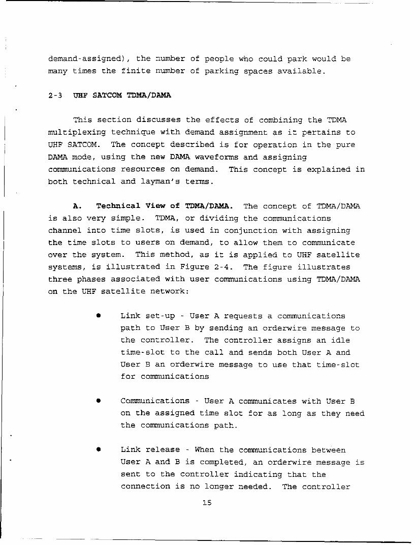
three phases associated with user communications using TDMA/DAMA
on the UHF satellite network:
0 Link set-up - User A requests a communications
path to User B by sending an orderwire message to
the controller. The controller assigns an idle
time-slot to the call and sends both User A and
User B an orderwire message to use that time-slot
for communications
0 Communications - User A communicates with User B
on the assigned time slot for as long as they need
the communications path.
0 Link release - When the communications between
User A and B is completed, an orderwire message is
sent to the controller indicating that the
connection is no longer needed. The controller
15
1. Unk set-up 21... 1 Request link-upOrderwires 1 2 IN to User B
/ ' -' Assign time $lot/ '\< .. -- ~.~ for link-up
User User
User j Controller UserB
2. Communication ITwo-wayOrderwlres 1 2 0e* N communications
User I I UserB Controller B
3. Lnk release Orderwires N completeTime slot available
/" \
User UeB Controller
Figure 2-4. UHF SATCOM TDMA/DAMA Concept
then makes the time slot available to accommodate
other service requests.
Since there is a pool of channels, which can be divided
into many communications paths (time slots), many users can be
communicating simultaneously. And since all do not need to
communicate at the same time, many more can be served than if
each net of users is assigned a dedicated communications path.
B. Layman's View of TDMA/DAMA. Continuing to use our
parking example, with a parking space representing a UHF SATCOM
communications channel for a user net, we can make more
comparisons. We now will combine our multiplexing technique with
demand assignment. Instead of using the parallel parking method,
16
we will park diagonally (multiplex) and have three times as many
parking spaces as before. As before, in a pure demand-assigned
situation, a person needing a parking space takes any one that is
available and uses it until he is finished. When he leaves,
another person can park there. We can control access by
authorizing users to use spaces through parking permits or
stickers, or making people see the parking attendant before they
take a space. The parking attendant becomes the controller of
the available spaces.
2-4 UHF SATCOM DAMA MODES
The area most misunderstood about UHF DAMA involves the
various modes in which it can operate. This section explains the
vast flexibility and capability of the UHF DAMA system to meet
all user situations. The important message in this section is
that UHF DAMA has not taken away any of the capabilities that
exist today, but rather has significantly enhanced availability
of UHF SATCOM to users. The system can provide all of the
following modes simultaneously:
A. Technical View of the DAMA Modes. This section
presents the technical view of the three DAMA modes supported by
the DAMA standards.
1. Dedicated Access. This mode is the way the system
is operated today. A user net is assigned a UHF SATCOM channel
for communications and no other users can use it. Either a 5-kHz
or a 25-kHz channel can be assigned for dedicated use. The
terminals communicating on the dedicated channel do not operate
using the DAMA waveform, but rather in the conventional mode.
Using operating procedures yet to be developed for system
management and control, a terminal operating in the DAMA waveform
could request a dedicated channel via the orderwire, get an
assignment, then switch to that channel and operate in the
conventional mode.
17
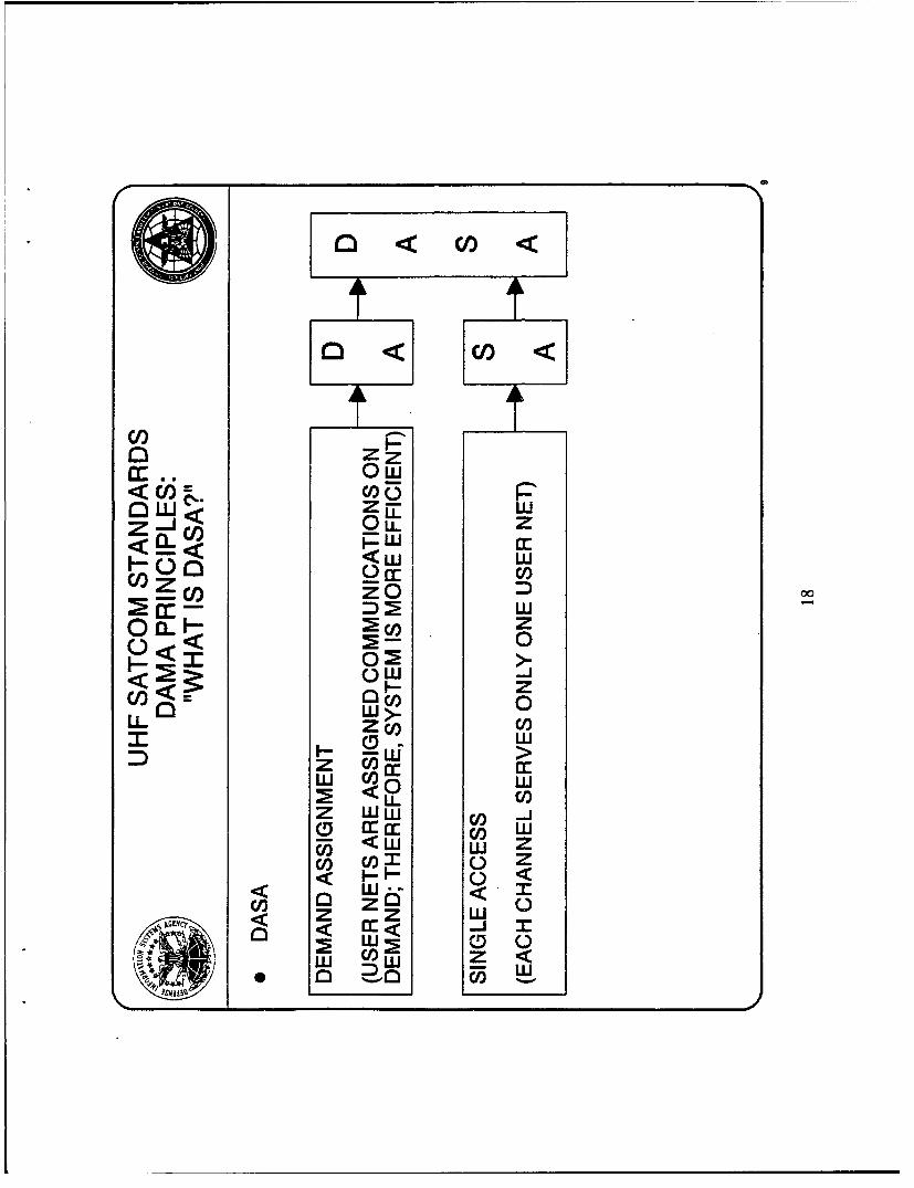
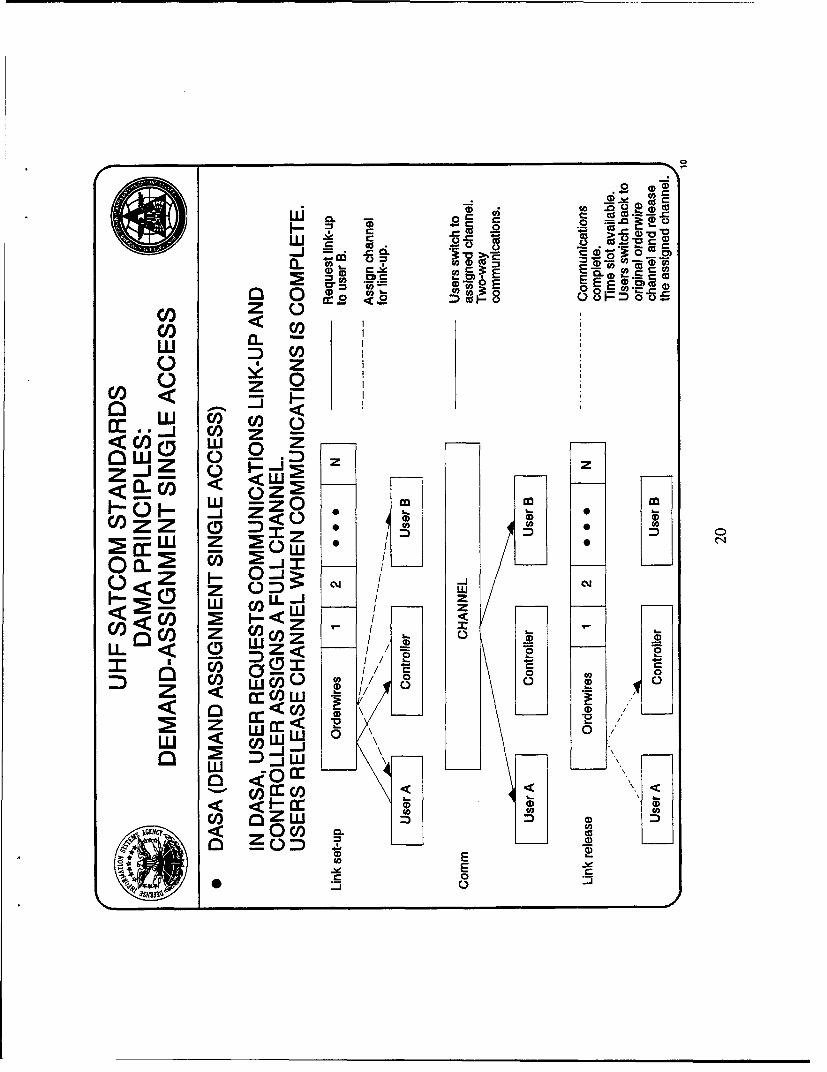
2. Demand-Assiqned Single Access. This mode was
added in the last revision of the DAMA standards to address the
problems of waveform delays within the demand-assigned mode.
This mode is implemented with a terminal operating in the DAMA
waveforms. A request for a single channel is placed on the
orderwire, the controller assigns an idle channel (either
5- or 25-kHz, depending on bandwidth requirements, availability,
or both), the communicating terminals receive the assignment over
the control orderwire, switch to the assigned channel, and
operate in the conventional mode on the assigned channel. When
they are finished communicating, they switch back to the DAMA
waveform, send a Call Complete message on the orderwire, and
continue operating in the DAMA mode as usual. Essentially, this
mode provides a dedicated channel for use by a net when they need
it. When they are not communicating, this channel is released
for use by others who need it. If one considers that the average
net uses a channel for 6 minutes an hour, and all nets usually do
not talk at the same time, sharing channels significantly
increases the number of nets that can get dedicated service when
they need it. One drawback of this mode is that while a net is
communicating on a DASA channel, orderwires are not received.
Therefore, preemption of the circuit cannot be accomplished.
This situation can be mitigated by limiting lower-priority users
to a fixed amount of time to use the DASA channel, while always
allowing priority 1 users unlimited use when they need it.
3. TDMA/DAMA. This mode allows all users access to
UHF SATCOM service based on their assigned priority. The
terminals operate in the DAMA waveform and request service when
they need it. The channels operating the DAMA waveforms are
divided into time slots that can provide various data rates to
accommodate both voice and data communications. Communicating
terminals are assigned time slots to use based on their assigned
priority. Priorities are assigned similar to the precedence
levels used in the Defense Switched Network (DSN). Users with
lower priorities can be preempted when a higher-priority user
18
must communicate and there are no idle time slots to provide the
service.
The concern of many users about DAMA is that they
want "assured access" to the system. The answer to this
requirement is to give all users requiring assured access the
highest priority, and limit that number of users to the number of
total available communications paths that can be set up at any
one time. This means that in the unlikely event all of these
high-priority users wanted to talk at exactly the same time,
there would be enough communications paths to accommodate them.
The beauty of this system is that there is a priority level for
everyone. The priority level can be dynamically upgraded or
downgraded, depending on assigned missions using the system
management and control network.
A low-priority user, who under the old system of
dedicated channel assignments would never have access to
communicate over the UHF SATCOM network, can request access to
the network anytime he wishes. If there are idle time slots, he
can get service. If he is denied service or gets preempted, he
will learn to use the system at off-peak times, but he will still
be able to communicate, where before he did not even have an
opportunity. The users who have the dedicated channels now will
get the highest priority and will have access whenever they need
it. The users with priorities in between will get better service
than they get right now with significantly less red tape and
coordination. Remember, however, that to have this great
improvement in capability and flexibility, something has to be
given in return. This is not to say that those who cannot afford
to give something up will be forced to. The system is flexibleenough to meet all special situations, if a user is willing to
pay the price for them. The price is discussed under the
resource allocation chapter of this tutorial, Chapter 4.
19
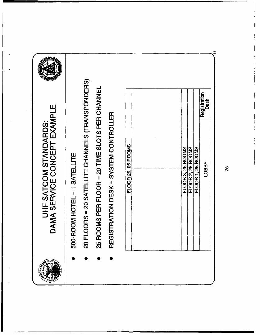
B. Layman's View of the DAMA Modes. To explain the DAMA
modes, let us introduce another example and compare the TDMA/DAMA
concept to a large hotel. This hotel has 500 rooms on 20 floors
with 25 rooms per floor. The hotel itself represents a satellite
with 20 transponders (channels). Each floor of the hotel
represents one of the satellite's transponders or channels.
Since the channels can be divided into time slots for
communications, the rooms on a floor represent communications
time slots. The hotel registration desk represents the system
controller. For the sake of time comparison, let us say that a
day's stay at the hotel is equal to 1 minute of a UHF SATCOM
communications duration. Having made these comparisons and
representations, let us draw comparisons to using the space
available in this hotel to the resources of a UHF SATCOM
satellite.
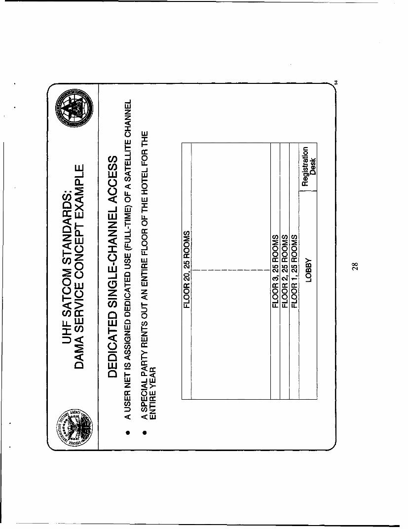
1. Dedicated-Channel Single Access. We could
represent this situation by saying that whenever the President
comes to this city, he stays at this hotel. The hotel sets aside
an entire floor for him. For security purposes, this floor is
never used for any other purpose other than for the President'svisits. It remains secure and not used, even when he is not
visiting this city.
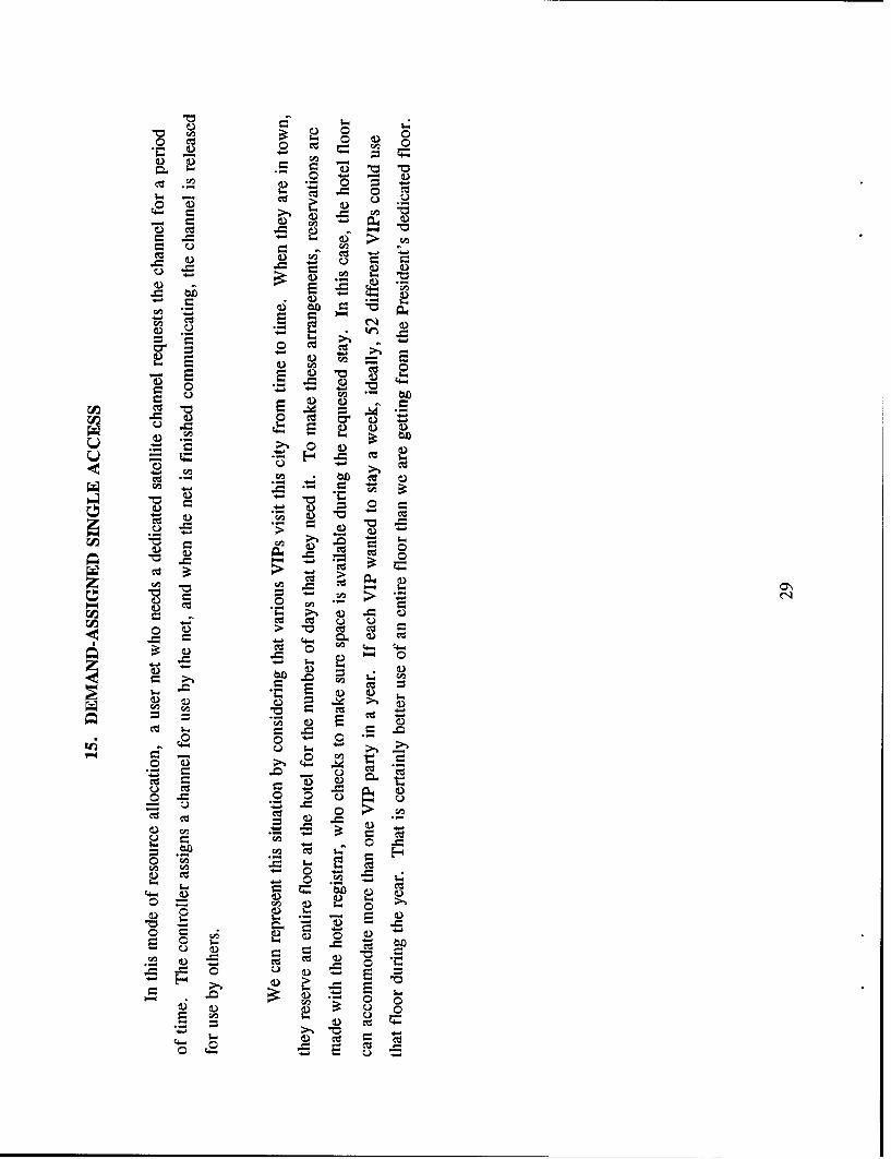
2. Demand-Assigned Single Access. We can represent
this situation by considering that various VIPs visit this city
from time to time. When they are in town, they reserve an entire
floor at the hotel for the number of days that they need it. To
make these arrangements, reservations are made with the hotel
registrar, who checks to make sure there is available space
during the requested stay. In this case, the hotel floor can
accommodate more than one VIP party in a year. If each VIP
wanted to stay a week, ideally, 52 different VIPs could use that
floor during the year. That is certainly better use of an entire
floor than that from the President's dedicated floor.
20
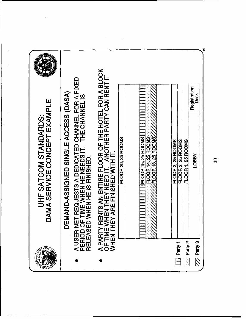
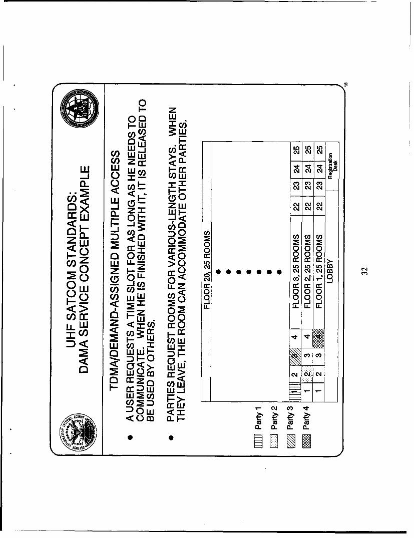
3. TDMA/DAMA. We can represent this mode by
considering that when people are visiting this city on travel,
they call ahead to the hotel registrar to reserve a room for
their stay. The reservation system assures that they have
sufficient space at the appropriate time for all people who have
requested rooms. The rooms are used by a number of different
people only when they need them. Under this plan, 25 different
individuals can have rooms every night on each floor. Thousands
of different people can be accommodated by one floor in an entire
year. Tens of thousands of people can be accommodated by all the
floors of the hotel in this mode of operation; however, let us
remember that we can still set aside the one floor for the
President, we could set aside a couple of floors for visiting
VIPs, and use the rest for the people who just need a room for a
couple of nights. We can do it all simultaneously, and it is the
same with the DAMA system. It is all a matter of configuring the
resources to meet the requirements of the customers/users. We do
this allocation of resources through the management and control
system, which will be in charge of programming the system
controllers that control access to the UHF SATCOM network.
2-5 DEFINITION OF VOICE SERVICES SUPPORTED BY DAMA STANDARDS
This section defines the various voice services supported
by the DAMA standards. The services are divided into three
segments governed by the type of control orderwire from which
services are assigned. For example, if a terminal is operating
in the 25-kHz DAMA waveform, it is receiving and sending
orderwires on its assigned "home channel." Some terminals will
operate with 25-kHz home channels, while others will operate with
5-kHz DAMA on 5-kHz home channels. System control can direct any
terminal to change its home channel, frequency band of operation,
or both. The purpose of identifying the various voice services
available is to demonstrate the set-up and communications delays
that can be expected for each of these services.
21
The orderwires for the 5-kHz and 25-kHz waveforms use
different nomenclatures. Orderwires from the controller to the
terminals are called forward orderwires (FOW) for 5-kHz and
channel control orderwires (CCOW) for 25-kHz waveforms.
Similarly, orderwires from the terminals to the controller are
called return orderwires (ROW) for 5-kHz and return channel
control orderwires (RCCOW) for 25-kHz waveforms.
A. 25-kHz Orderwire. Voice services available through the
25-kHz orderwire are summarized below. The delays for set up of
a service are primarily associated with the number of orderwire
slots and the time delay between orderwire transmissions. In the
case of UHF DAMA, orderwires are sent every frame, so the major
limiting factor for call set up is the frame length, which is 1.4
seconds for the 25-kHz DAMA waveform.
1. TDMA/DAMA Services. Service requests for
TDMA/DAMA voice may be satisfied by providing either a 2.4-kbps
time slot for narrowband voice or providing a 16-kbps time slot
for wideband voice. In 25-kHz TDMA/DAMA operation, a time slot
can be assigned on a terminal's home channel or on any other DAMA
operating channel in that satellite. If the terminal is
communicating on other than its home channel, it must switch back
to its home channel every frame to monitor the control orderwire
during the CCOW interval.
2. DASA Services. Service requests for DASA service
may be satisfied from terminals operating in the 25-kHz waveform
via their home-channel orderwire. Services offered are either
2.4 kbps on a 5-kHz channel or 16 kbps on a 25-kHz channel. The
controller instructs the terminal to leave its home channel and
switch to an idle channel to operate, using MIL-STD 188-181.
When communications are complete, the terminal returns to its
home channel and sends a Call Complete message to signal to the
controller that the channel is available for reassignment.
Notice that while terminals are communicating on the DASA
22
channel, they do not receive any orderwires. This drawback
results in the loss of preemption capability of the DAMA system.
The drawback is controlled by assigning terminals a time limit
for use of the channel. The time limit is based on a user's
priority.
B. 5-kHz Orderwire. Voice services available through the
5-kHz orderwire are summarized below. As in the 25-kHz mode, the
delays for set up of a service are primarily associated with the
frequency of the orderwires and the time delay between orderwire
transmissions. In the case of the 5-kHz DAMA waveform,
orderwires are sent every frame, so the major limiting factor for
call set up is the frame length, which is about 9 seconds.
1. TDMA/DAMA Services. Service requests for DAMA
voice may be satisfied by providing a 2.4-kbps time slot for
narrowband voice. In 5-kHz TDMA/DAMA operation, a time slot must
be assigned on a terminal's home channel, because the waveform
protocols cannot support communicating on 1 channel while
monitoring the orderwire on another channel, as does the 25-kHz
waveform.
2. DASA Services. Service requests for DASA service
may be satisfied from terminals operating in the 5-kHz waveform
via their home-channel orderwire. Services offered are either
2.4 kbps on a 5-kHz channel or 16 kbps on a 25-kHz channel. The
controller instructs the terminal to leave its home channel and
switch to an idle channel to operate, using MIL-STD 188-181.
When communications are complete, the terminal returns to its
home channel and sends a Call Complete message to signal to the
controller that the channel is available for reassignment.
C. Dedicated. This mode represents the manner in which
channels are assigned today. Voice services can occur using
either 2.4 kbps on a 5-kHz channel or 16 kbps on a 25-kHz
channel. This mode can be implemented on a pre-arranged basis or
23
from the DAMA mode through assigning an indefinite time limit
DASA channel.
24
CHAPTER 3
UHF DAMA SET-UP AND COMMUNICATIONS DELAYS
The purpose of this chapter is to present to the user the
set-up and communications delays for the various voice services
supported by the DAMA standards, and to provide estimates of the
expected delays for each voice service. The delays are presented
with respect to the steps that a user must logically take to
establish communications over a UHF SATCOM link in the three
different modes of DAMA operation. Below are the three
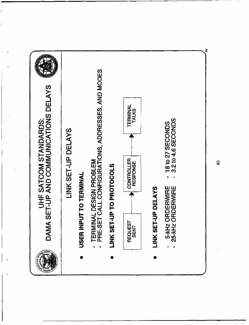
categories of delays:
"* Terminal Set-up Delays - The time it takes to set up
the terminal to get ready to communicate.
"* Link Set-up Delays - The time it takes to establish a
communications path with called user or net.
"* Waveform Delays - The time delay associated with
buffering voice signals that is required to operate in
the TDMA waveform.
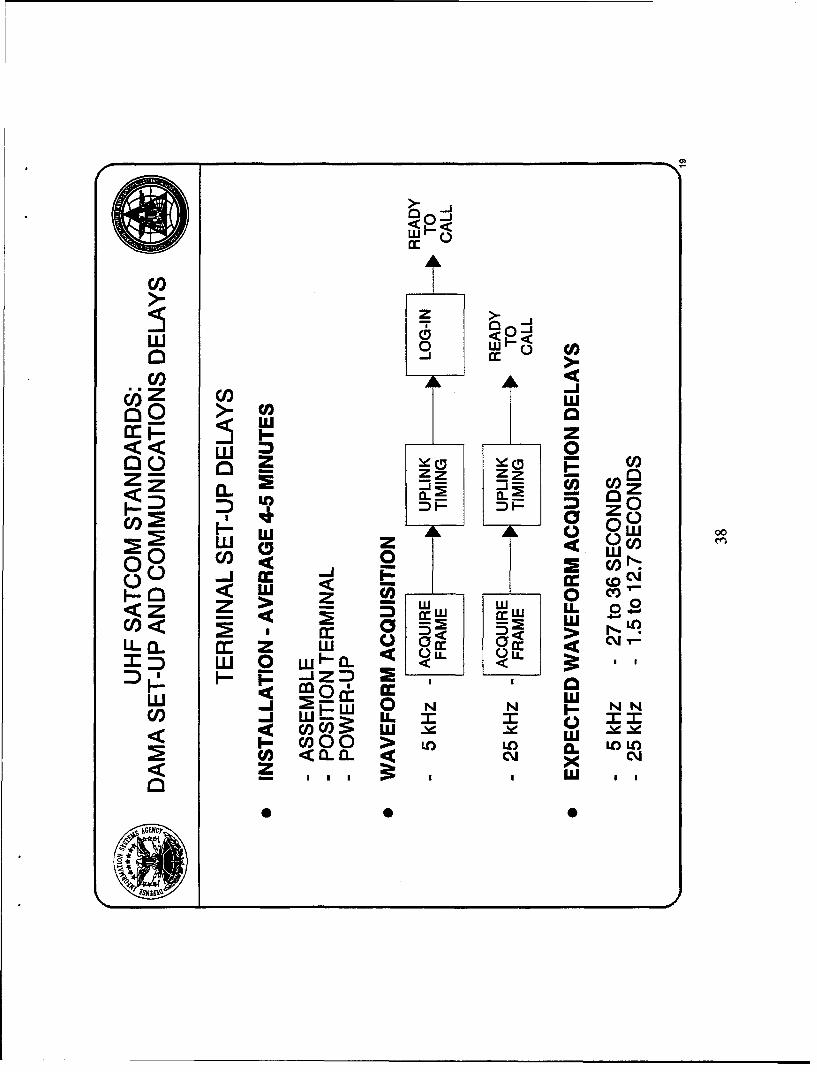
3-1 TERMINAL SET-UP DELAYS
Terminal set-up delays consist of two elements: terminal
installation and waveform acquisition. These delays can be
viewed as those experienced between the time it is decided to
install a terminal until the terminal is prepared to accept a
user request for communications service.
A. Terminal Installation. This delay is the time required
to physically prepare the terminal for communicating. For a
manpack terminal, this is the time required to remove the
terminal from the pack, deploy and orient the antenna, connect
all cables, turn the power on and warm up, and initialize the
25
terminal. Based on information provided by UHF SATCOM users,
during DAMA briefings, an average time to perform these actions
is 4 to 5 minutes. (Special Operations personnel have stated
this can be reduced to 2-3 minutes, but, on the average, 4 to 5
minutes is typical.) The AN/PSC-5 specification calls for
terminal installation within 2 minutes. This delay is not unique
to the new waveforms being implemented, except for terminal
initialization, which requires seconds to complete. Therefore,
the terminal initialization delay will not be considered further.
B. Waveform Acquisition. This delay is the time required
to synchronize with the TDMA waveform, which is essential to
permit terminals to participate in the network. To request
service, 5-kHz users must also login with the DAMA controller,
and login takes a finite time to complete. To establish a basis
for delay analysis, it is assumed that the actions required to
attain waveform acquisition are sequentially performed
automatically by the terminal equipment, following operator
initiation via key commands. Each of the actions described below
must be completed in the order discussed. The minimal delay
identified in the following paragraphs is a function of
transmitter turn-on time and the delays internal to the terminal
equipment for forwarding commands to the receiver or transmitter.
For example, in the case of the AN/PSC-5, the transmitter and
receiver turn-on time is .875 milliseconds. This turn-on time
and other internal terminal delays depend on terminal design.
These waveform acquisition delays apply only to the TDMA/DAMA and
DASA modes.
1. 5-kHz Waveform Acquisition Delays. Acquisition
delays include the time required to complete downlink
acquisition, uplink acquisition, and login.
a. Downlink Acquisition. The terminal must
acquire and interpret the forward orderwire (FOW) transmitted
from. the DAMA controller. This is the first action required to
26
synchronize terminal timing with the TDMA frame. The actions
required to perform this synchronization and interpretation
consist of acquiring downlink symbol, time slot, and frame
timing, and decoding the FOW.
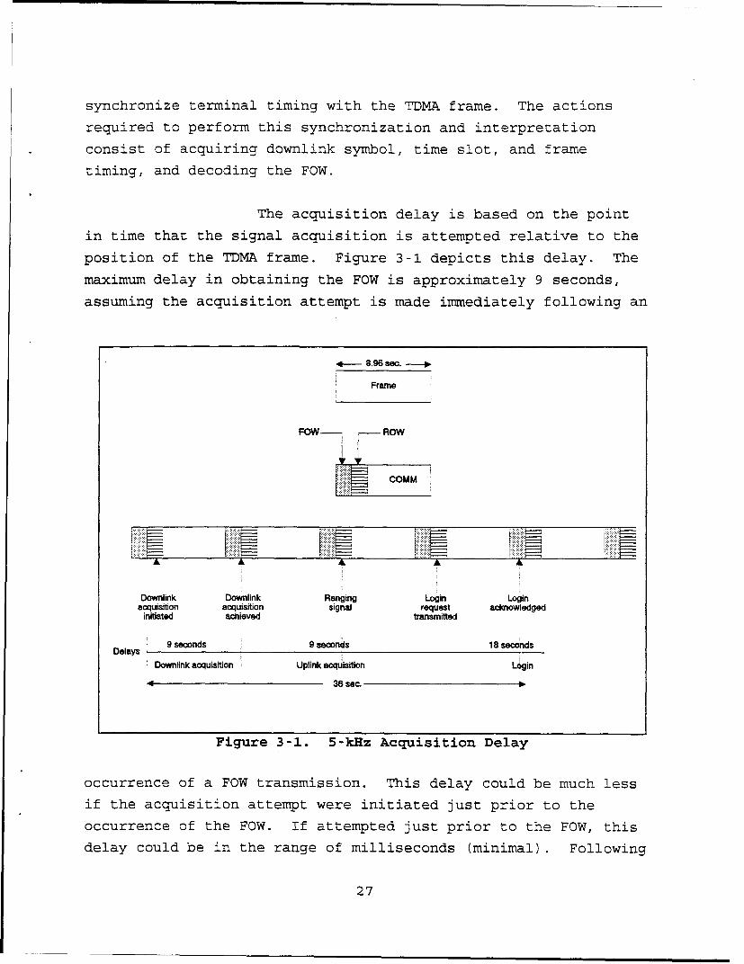
The acquisition delay is based on the point
in time that the signal acquisition is attempted relative to the
position of the TDMA frame. Figure 3-1 depicts this delay. The
maximum delay in obtaining the FOW is approximately 9 seconds,
assuming the acquisition attempt is made immediately following an
4- 8.96 sec. -*
Frame
FOW- -ROW
Comm
A A
Downlink Downlink Ranging Login Loginacquisition acquisition signal request acknowledged
initiated achieved transmitted
S seconds 9 seconds 18 secondsDelays n
Downlnk acquisition Uplink acquisition L6gin
36 sec.
Figure 3-1. 5-kHz Acquisition Delay
occurrence of a FOW transmission. This delay could be much less
if the acquisition attempt were initiated just prior to the
occurrence of the FOW. If attempted just prior to the FOW, this
delay could be in the range of milliseconds (minimal). Following
27
receipt of the first FOW signal, the synchronization process is
completed.
The activity of other terminals in acquiring
the downlink synchronization has no effect on a terminal's
ability to perform this step. The term used to indicate that
possible interference among terminals can occur is called
contention, meaning that terminals are sharing a resource and the
possibility exists that they may try to perform an action at the
same time and interfere with one another. Normally contention is
concerned with a transmit action, and since downlink acquisition
is a receiving process, no contention is experienced with
accomplishing this acquisition.
b. Uplink Acquisition. Uplink acquisition is
the next step in aligning terminal timing with that of the TDMA
frame. This is accomplished by a procedure called ranging. For
initial entry into a network, two methods of ranging may be used,
active ranging and passive ranging. Active ranging is performed
by transmitting a short burst to the satellite and calculating
the time delay for a signal to travel from the terminal to the
satellite. This transmission is done in the return orderwire
(ROW) time slot allocated for ranging, called the contention-
ranging time slot. The 5-kHz waveform provides a variable number
of contention-ranging time slots in each frame. The number of
contention-ranging time slots available in the next frame is
contained in the FOW.
Terminals properly equipped can perform
passive ranging to determine timing and do not have to transmit a
burst in the ROW. It should be noted that the new Enhanced
Manpack UHF Terminal (EMUT) can perform passive ranging. The
time required to complete this passive ranging will not be
addressed in this tutorial.
28
The earliest time that uplink acquisition can
be accomplished is the ROW time slot in the frame following the
receipt of an FOW. This delay is required to determine which
time slots are available for ranging in the next frame. Figure
3-1 depicts this delay of approximately 9 seconds, which occurs
between receipt of the last FOW and occurrence of the ROW in the
next frame. This delay would be minimal if the acquisition were
initiated just prior to the occurrence of a FOW.
If a large number of terminals attempt
ranging simultaneously, collisions can occur. This means that
two or more terminals have transmitted in the same time slot, and
all transmitted information is lost. Under these circumstances,
each terminal waits and retransmits in a randomly selected future
frame and a randomly selected time slot within that frame.
Appendix A discusses the random delay algorithm and the
associated delays in further attempts to attain uplink
acquisition.
c. Terminal Login. Prior to initiating user
requests for service, each terminal must login with the DAMA
controller. This is accomplished by transmitting a Login message
in the ROW and receiving a positive acknowledgment in a Login
Response message via the FOW. This login message includes
information concerning data-rate capability, link-quality
requirements, guard list, and terminal type. This information
insertion into the terminal is part of the initialization
discussed under terminal installation.
These time delays are experienced by any
terminal operating in the DASA or TDMA/DAMA mode of operation.
Figure 3-1 depicts the delays experienced in login. The first
ROW available for login occurs 9 seconds later than the one used
for ranging. Upon receipt of this login request, the DAMA
controller transmits a login acknowledgment message, which is
transmitted in the first available FOW or approximately 9 seconds
29
later. This results in an approximate delay of 18 seconds after
completion of uplink acquisition to complete login, assuming no
collisions have occurred.
As with the ranging transmissions, there is
contention for access to the ROW time slots. If a login
acknowledgment is not received within 4 frames following
transmission of the login request, or a total of 36 seconds, the
terminal assumes the request was not received by the DAMA
controller. In this situation, the terminal automatically
retransmits login requests after random delays. Appendix A
discusses the algorithm for retransmission of login requests and
how they affect delays.
Note that the login requirement can be
bypassed if the terminal login was done previously with the DAMA
controller. This is referred to as preassigned login.
Preassigned login must include all information included in the
ROW login message.
2. 25-kHz Waveform Acquisition Delays. Acquisition
delays include the time to acquire synchronization for both the
downlink and uplink.
a. Downlink Acquisition. This downlink
acquisition serves the same function as for the 5-kHz waveform.
Due to differences in frame lengths and design, the delays are
different than those for the 5-kHz waveform. This acquisition is
referred to as receive timing acquisition for the 25-kHz waveform
and is based on the terminal's achieving frame synchronization
lock on the CCOW transmitted from the DAMA controller. Frame
lock is achieved when the terminal successfully receives two
consecutive CCOW transmissions.
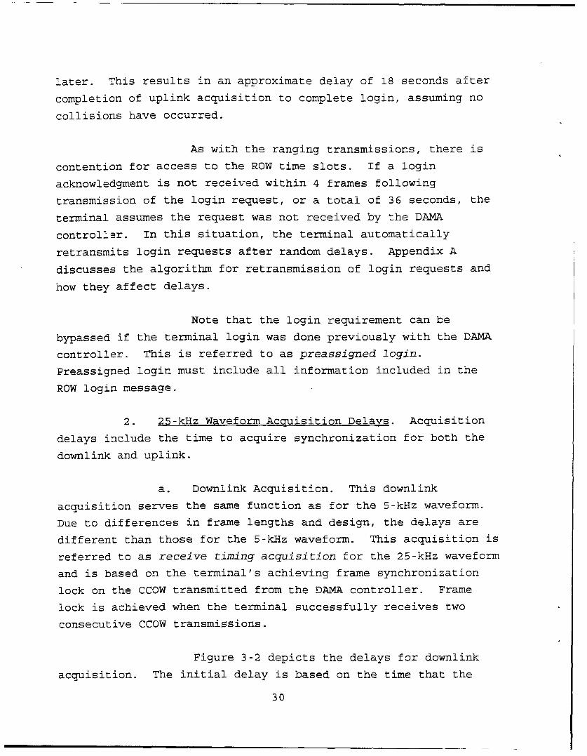
Figure 3-2 depicts the delays for downlink
acquisition. The initial delay is based on the time that the
30
- 1.3868 sec.
Frame
CCOW-- Range
4 - Even frame -. - - - Odd frame - 1--- Even frame - ---- Odd frame 10
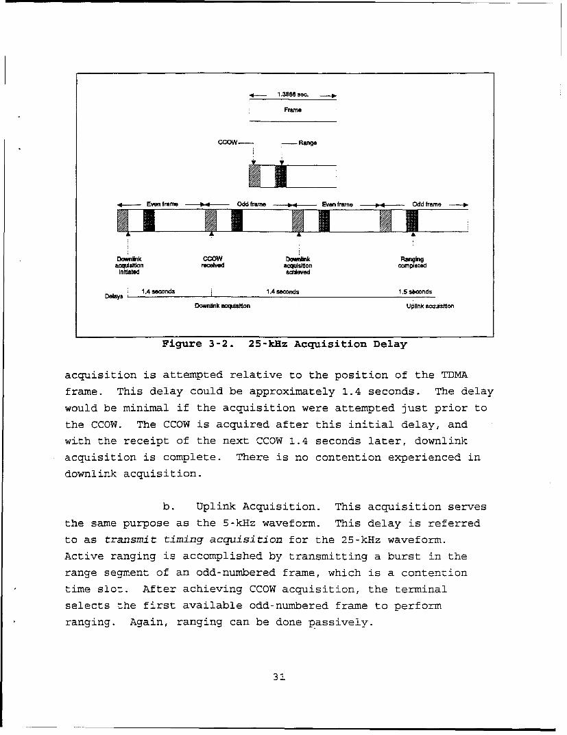
Downilnk cCow Oounink Rangingacutisition reoelved acqulision completed
Initiated achieved
Delays 1.4 seconds 1.4 seconds 1.5 seconds
Downlink acquisition Uplink acquisition
Figure 3-2. 25-kHz Acquisition Delay
acquisition is attempted relative to the position of the TDMA
frame. This delay could be approximately 1.4 seconds. The delay
would be minimal if the acquisition were attempted just prior to
the CCOW. The CCOW is acquired after this initial delay, and
with the receipt of the next CCOW 1.4 seconds later, downlink
acquisition is complete. There is no contention experienced in
downlink acquisition.
b. Uplink Acquisition. This acquisition serves
the same purpose as the 5-kHz waveform. This delay is referred
to as transmit timing acquisition for the 25-kHz waveform.
Active ranging is accomplished by transmitting a burst in the
range segment of an odd-numbered frame, which is a contention
time slot. After achieving CCOW acquisition, the terminal
selects the first available odd-numbered frame to performranging. Again, ranging can be done passively.
31
As noted in Figure 3-2, if downlink
acquisition were completed in an even frame, the terminal would
have to wait slightly more than 1 complete frame to transmit the
ranging signal or approximately 1.536 seconds. The .136 seconds
is the length of User Segment A of the waveform that lies between
the CCOW and Range time slots. Note that if downlink acquisition
were completed in an odd frame, the terminal could transmit the
ranging signal within the same frame. The delay in this case
would be approximately .136 seconds or the length of User Segment
A of the waveform.
There is an additional delay that could be
experienced in achieving uplink acquisition, which is related to
receiving and interpreting the master frame. The master frame
occurs every 11.1 seconds (8 frames) and contains frame format
and other parameters needed to operate on the channel, including
designation of which frames are odd and even. During downlink
acquisition the CCOW is received and interpreted. Two
consecutive CCOWs are received to accomplish this acquisition.
If the initial CCOW interpreted during downlink acquisition is
the one immediately following the master frame, there is a delay
of 6 frames (8.4 seconds) to receive and interpret the master
frame. This delay is not experienced if one of the CCOWs
interpreted during downlink acquisition is in a master frame.
If active ranging is unsuccessful due to
collisions, the terminal performs additional ranging based on a
random process. Appendix A discusses the delays associated with
follow-on attempts to complete the ranging procedure.
c. Login. No defined procedure exists in
MIL-STD-188-183 for how a terminal logs onto the 25-kHz DAMA
network. The RCCOW does not define such a message. Login is
accomplished with a service request or link set-up, discussed
below in paragraph 3-2.
32
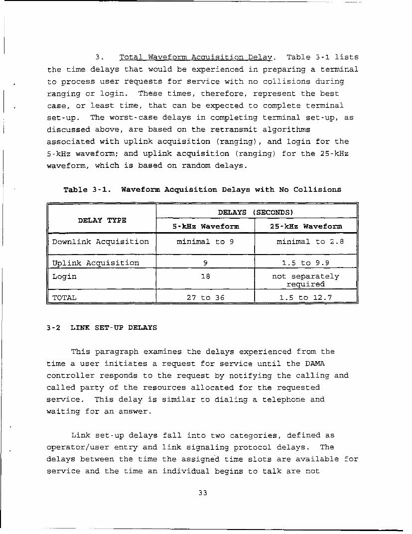
3. Total Waveform Acquisition Delay. Table 3-1 lists
the time delays that would be experienced in preparing a terminal
to process user requests for service with no collisions during
ranging or login. These times, therefore, represent the best
case, or least time, that can be expected to complete terminal
set-up. The worst-case delays in completing terminal set-up, as
discussed above, are based on the retransmit algorithms
associated with uplink acquisition (ranging), and login for the
5-kHz waveform; and uplink acquisition (ranging) for the 25-kHz
waveform, which is based on random delays.
Table 3-1. Waveform Acquisition Delays with No Collisions
DELAYS (SECONDS)DELAY TYPE
5-kHz Waveform 25-kHz Waveform
Downlink Acquisition minimal to 9 minimal to 2.8
Uplink Acquisition 9 1.5 to 9.9
Login 18 not separatelyrequired
TOTAL 27 to 36 1.5 to 12.7
3-2 LINK SET-UP DELAYS
This paragraph examines the delays experienced from the
time a user initiates a request for service until the DAMA
controller responds to the request by notifying the calling and
called party of the resources allocated for the requested
service. This delay is similar to dialing a telephone and
waiting for an answer.
Link set-up delays fall into two categories, defined as
operator/user entry and link signaling protocol delays. The
delays between the time the assigned time slots are available for
service and the time an individual begins to talk are not
33
considered, since this delay is variable, based on operator
experience.
A. Operator/User Entry. The delay in initiating a service
request when operating in the TDMA/DAMA and DASA modes is minimal
but does take more time to complete than for communicating in the
dedicated mode. For the dedicated mode, the handset is picked
up, the called party is signaled, and talking begins. The only
delay experienced in this case is the time required to initiate
the signaling and the propagation time for the signal to travel
over the satellite system, which is 238 milliseconds.
TDMA/DAMA and DASA operation require additional
operator action to develop the circuit set-up request message.
This message includes 10 separate entries by the operator for 5-
kHz operations. The additional delay is only a few seconds.
These delays apply to both 5- and 25-kHz DAMA operations. The
standards have no control over this delay. However, the
specifications for the terminals can include requirements for
preset calling lists and other preprogramming options to reduce
this delay. This delay will not be considered further.
B. Link Signaling Protocol. These delays are those
associated with waiting for allocation of resources to
communicate with another user, following initiation of a request
for service. The delays experienced when requesting service
using the DAMA orderwire system are determined primarily by the
frame design and apply to TDMA/DAMA and DASA modes.
1. 5-kHz Waveform. The delays experienced are
determined primarily by the long frame length, which is
approximately 9 seconds. When a user request is initiated, the
terminal prepares a ROW Circuit Setup Request message for
transmission to the DAMA controller. Upon receipt of the ROW
message, the DAMA controller determines whether the requested
34
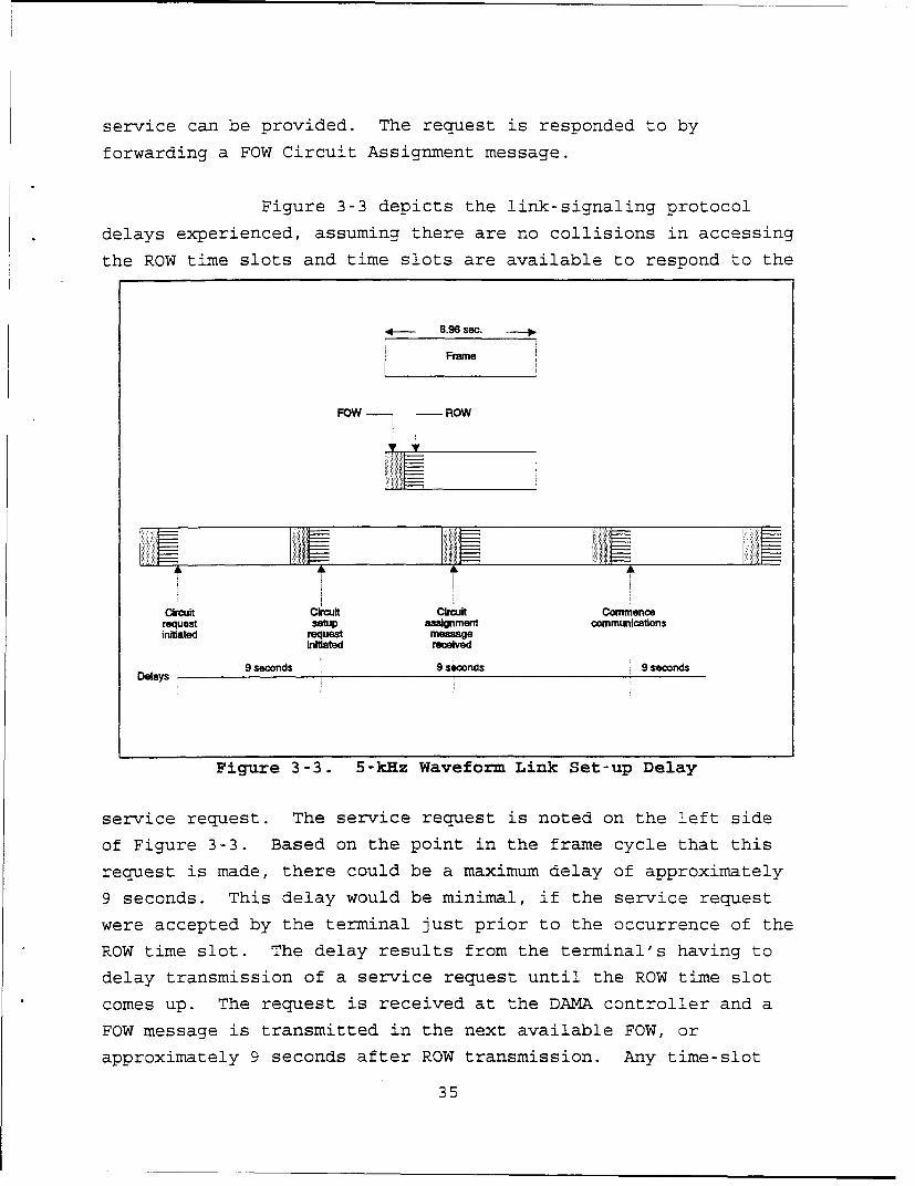
service can be provided. The request is responded to by
forwarding a FOW Circuit Assignment message.
Figure 3-3 depicts the link-signaling protocol
delays experienced, assuming there are no collisions in accessing
the ROW time slots and time slots are available to respond to the
- 8.96 sec. --
Frame
FOW- ROW
14=Tm
Circuit Crcuit Circuit Commencerequest setup assignment communicationsinitiated request message
Initiated received
9 seconds 9 s$conds 9 secondsDelays
Figure 3-3. 5-kHz Waveform Link Set-up Delay
service request. The service request is noted on the left side
of Figure 3-3. Based on the point in the frame cycle that this
request is made, there could be a maximum delay of approximately
9 seconds. This delay would be minimal, if the service request
were accepted by the terminal just prior to the occurrence of the
ROW time slot. The delay results from the terminal's having to
delay transmission of a service request until the ROW time slot
comes up. The request is received at the DAMA controller and a
FOW message is transmitted in the next available FOW, or
approximately 9 seconds after ROW transmission. Any time-slot
35
assignment designated in the FOW for communications would be for
the next frame, not the current one, so there is another 9-second
delay before the user could begin communications with the called
party. Therefore, the user can begin communications within 18 to
27 seconds from the time the service request was initiated.
For the DASA mode, the 5-kHz DAMA orderwire is
used to assign a single 5-kHz channel or a 25-kHz channel, using
a Terminal Channel Assignment FOW message. The terminal must
respond with a ROW, in a time slot assigned by the DAMA
controller, to acknowledge the channel change. As done for
TDMA/DAMA operation, all time slots are assigned for the next
frame following receipt of the FOW circuit assignment. Thus, for
DASA operations, the delay for circuit setup would also be 18 to
27 seconds.
In both the TDMA/DAMA and DASA modes, there could
be collisions on the ROW, and the service request may not be
received at the DAMA controller. Should this happen, there would
be a 30-second delay before the terminal assumes the ROW was not
received by the DAMA controller. Should this happen, the
terminal selects a random future frame to retransmit the service
request message. Appendix B discusses the delays associated with
further transmissions of service requests under these
circumstances.
Should time slots not be available to satisfy the
service request, the DAMA controller would forward a FOW
acknowledgment message to advise that the service request is
queued or why the request was rejected. This message should be
received by the terminal within 4 frames, or 36 seconds, after
transmission of the service request. If the request were placed
in a queue, the delay in responding to the request would be
variable, based on the level of traffic, including such things as
priority of users requesting service or whether the called party
is engaged in another call.
36
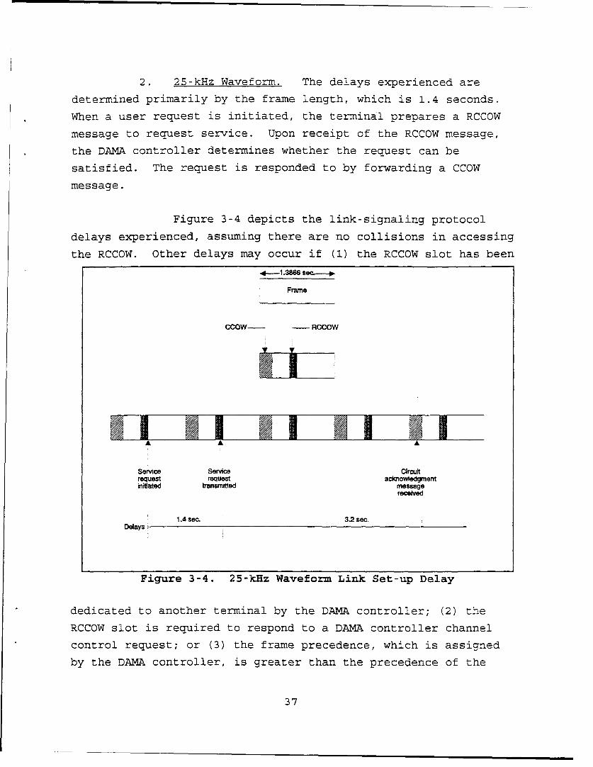
2. 25-kHz Waveform. The delays experienced are
determined primarily by the frame length, which is 1.4 seconds.
When a user request is initiated, the terminal prepares a RCCOW
message to request service. Upon receipt of the RCCOW message,
the DAMA controller determines whether the request can be
satisfied. The request is responded to by forwarding a CCOW
message.
Figure 3-4 depicts the link-signaling protocol
delays experienced, assuming there are no collisions in accessing
the RCCOW. Other delays may occur if (1) the RCCOW slot has been
-1 .3866 sec.-j..
Frame
MOW- - RCCOW
SSce Sevice Circuitrequest request acknoWedgmentiniated transmitted message
receved
1.4 sec- 3.2 sec.Delays
Figure 3-4. 25-kHz Waveform Link Set-up Delay
dedicated to another terminal by the DAMA controller; (2) the
RCCOW slot is required to respond to a DAMA controller channel
control request; or (3) the frame precedence, which is assigned
by the DAMA controller, is greater than the precedence of the
37
RCCOW. These delays depend on traffic loading statistics and
cannot be projected without extensive modeling.
Figure 3-4 delays assume lack of collisions and
other delays in accessing the RCCOW, and the DAMA controller can
assign time slots for the requested communications. The service
request initiation is noted on the left side of the figure.
Based on the point in the TDMA frame that this request is made,
there could be a 1.4-second delay. This delay could be minimal
if the request were provided to the terminal just prior to the
occurrence of the RCCOW. The service request would be
transmitted in the first available RCCOW. This service request
would be acknowledged via a CCOW transmission and received at the
terminal within the third frame after transmission of the RCCOW
service request. This would result in a 2-frame delay (2.8
seconds) plus the time between the RCCOW and the start of the
CCOW (.37 seconds). Therefore, a delay of between 3.2 and 4.6
seconds would be experienced between service request initiation
and the start of communications.
In the event of a collision on the RCCOW, the
terminal waits 3.2 seconds for an acknowledgment that will not be
received. If an acknowledgment is not received, the terminal
selects a future frame to retransmit the service request.
Appendix B discusses the delays associated with retransmission of
additional service requests.
Other delays that can be experienced in link setup
are indicated below:
* There are limits placed on the use of the
RCCOW through an assignment method in theCCOW, which makes these slots unavailable for
service requests. An example is when a
terminal is requested to send a status
report. This request must be responded to in
38
the next frame. This introduces an
additional delay for initiating a service
request, and these delays depend on traffic
statistics.
* Delays are experienced for those cases when
the called party is busy or the DAMA
controller is processing service requests of
higher priority. In this case, the DAMA
controller advises, in the Call
Acknowledgment message, that the call has
been placed in a queue. When placed in the
queue, the CCOW message includes the time
delay until the call can be serviced. This
time varies, based on traffic load, priority
of service requests, how busy the called
party is with equal or higher-priority
service requests, and whether the called
party has logged off the air for a preset
time. Should this occur, the DAMA controller
will process the request as soon as time
slots are available.
0 The DAMA controller can limit the call
requests to those above a certain priority
within specific frames. The delays
associated with this restriction depend on
traffic statistics. Should this occur, the
terminal maintains the call in a queue for
processing when time slots are available.
Note that if the standard were changed to permit
the controller to respond to a request for service in the next
frame instead of waiting for the third frame to respond, the link
setup delay could be reduced to 3 seconds.
39
3-3 WAVEFORM DELAYS
This paragraph addresses the delays that would be
experienced between the time one user finishes talking and the
spoken words are received by the called party. These delays are
caused by the TDMA frame structure, which requires that the data
bits resulting from voice digitization be buffered for insertion
into the designated TDMA time slot.
The user data stream, following analog-to-digital
conversion at 2400 bps, is input to a buffer for transmission at
the proper time sequence within the TDMA frame. This user data
is integrated with overhead information for proper operation and
transmitted at the start of the designated TDMA time slot. At
the receive end the overhead bits are removed and the user
telephone is provided with a data stream at 2400 bps. This
buffering delay applies only to the TDMA/DAMA mode.
A. 5-kHz Waveform Delays. The delays for this waveform
are 8.96 seconds. Interactive voice delay, which is that time
between talking and hearing the response from the called party
are completed, would be 17.9 seconds. This delay is an
impediment to operations. For example, roll call for a net of 5
users would take almost 2 minutes to ensure everyone was on line.
In addition, net discipline would be critical to prevent everyone
from talking at the same time.
B. 25-kHz Waveform Delays. The delays for this waveform
are 1.3866 seconds. Interactive voice delay is 2.7 seconds.
3-4 TOTAL DELAYS
Table 3-2 presents the results of the delays that will be
experienced for voice services defined in MIL-STDs 188-
181/182/183. The first two columns depict the voice service
options available for both the 5- and 25-kHz channels and reflect
40
use of optional orderwires to set up the circuit. This optional
use of orderwires is discussed in Chapter 2. The voice service
options are for 2.4- or 16-kbps voice, as noted. Note that the
link set-up delays are based on which orderwire is being employed
and results in a 6-fold decrease with use of the 25-kHz
orderwire. The waveform delays on the other hand are determined
by the waveform's being used for actual communications. The
delays shown constitute the extra time required above the time
experienced when operating in the dedicated mode, as is now done.
Transmission delay (earth terminal to satellite to earth
terminal) and terminal installation times are not included in
Table 3-2. All delays have been rounded off to the nearest tenth
of a second.
We can conclude from Table 3-2 that the Link Setup and
Waveform delays of the 5-kHz TDMA/DAMA are excessive for voice
service, and many users have stated that these delays will not
meet their requirements. In addition, the 5-kHz TDMA/DAMA mode
does not provide high efficiencies when it is used for voice.
Therefore, the Joint Interoperability and Engineering
Organization (JIEO) feels that 5-kHz TDMA/DAMA voice services
should never be allocated to high-priority users (for example,
communications higher than priority). Furthermore, low-priority
users should be assigned voice services on 5-kHz TDMA/DAMA only
when other modes are not available and only when channel
reconfiguration will introduce inefficiencies or interferences to
low-speed circuit and message traffic. This JIEO position will
be coordinated and will be formalized and incorporated in
MIL-STD-188-185, the DAMA Management and Control standard, which
is now being developed.
41
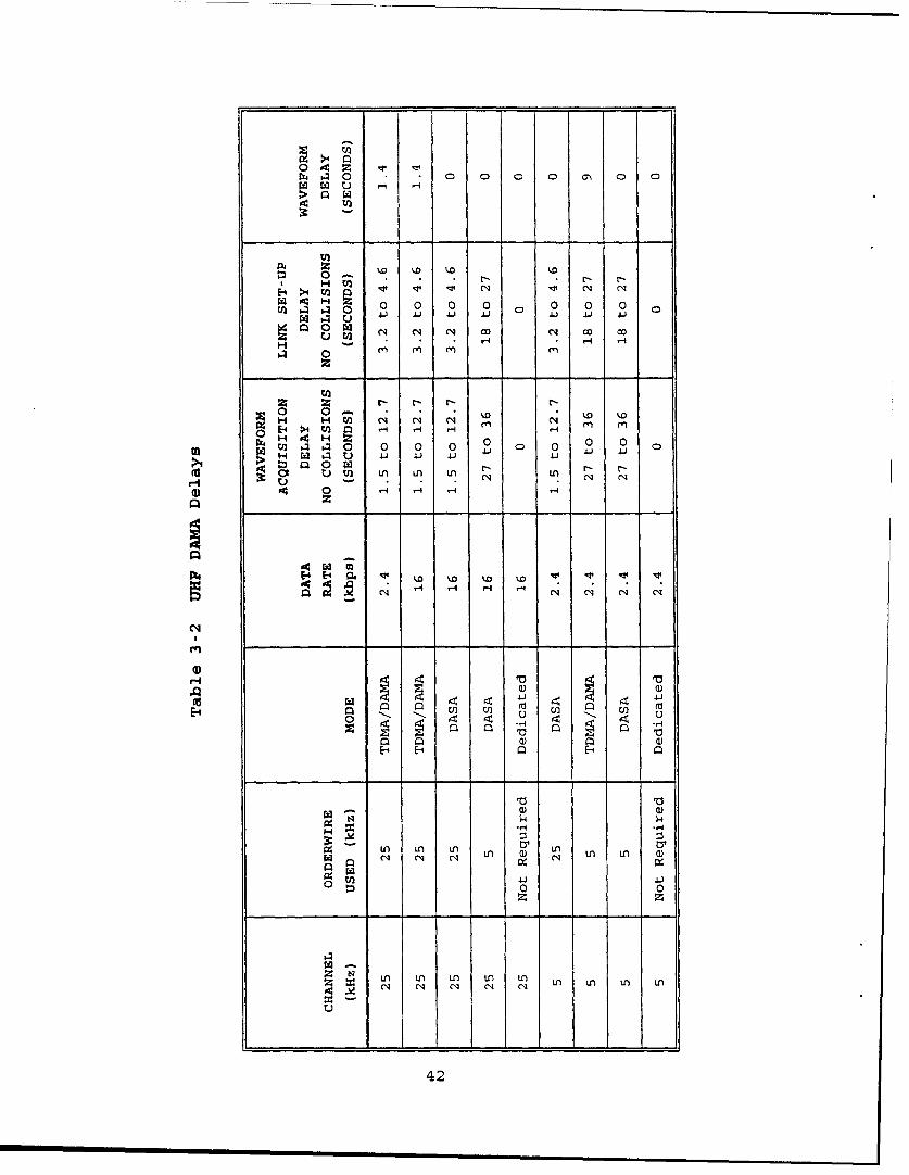
Cr4 14 0 0 0 on C)~
0 0 0 0 0 0 0w 41 41 4 4.) 41~ 41~ 4
N C14 Hq H3 HNcoHH
S0 0 . 'D
H H HH
1w 0 0 0 0 CD 0 0 0Ulu 4-1 41) -L 4 41 4
c , U V LA) LA LA U) ~'~ 0 H H H
4 r- H H
C',
00 4
E E-4 E-
'0 '0U) z
N LA) Ln LA LA LCNA C1 N CN LA LA U)
42
CHAPTER 4
ACCESS AND ALLOCATION OF UHF SATCOM RESOURCES
This chapter presents the access utilization procedures and
how they affect user resource allocation. It provides a brief
overview of the UHF SATCOM DAMA management and control concept
and a discussion of the problem of resource allocation for the
DAMA system. A solution to this problem is proposed, using an
apportionment method for allocating UHF SATCOM resources to user
organizations, and an example of the application of the
apportionment method is presented.
4-1 BACKGROUND
MIL-STD-188-185 will define the management and control
concepts for the UHF DAMA system. The control and management of
the satellite systems is defined as follows:
"* Control System - Executes the management and controlplans established by the resource manager. The control
system consists of equipment, procedures, and manpower
that configure satellite channels and assign access.
"* Resource Management - Encompasses planning functions
and provides direction to the DAMA system controller to
allocate satellite DAMA resources.
After a study and several Joint working-group sessions,
during which several alternative management and control conceptswere evaluated and discussed, the Joint Staff directed JIEC to
incorporate, into MIL-STD-188-185, a decentralized management and
centralized system control concept, in accordance with option C
of Reference F. This direction was issued in a Joint Staff
memorandum to JIEO, dated 24 November 1993.
43
The centralized system control and decentralized resource
management concept entails having all UHF SATCOM channels in each
footprint under one access system controller. The access system
controllers for each footprint are tied together and connected to
a central processing facility, which houses the management and
control database. The access system controllers are under the
jurisdiction of several authorities that provide management
directions for the space segment resource allocation through
their entries into their parts of the central database. The
system diagram for this concept is presented in Figure 4-1.
CONCEPT: All channels (in each footprint) are under one access system controller.The access system controller is under the jurisdiction of several authorties thatprovide management directions for space segment resource.Figure 4-1. Centralized System Control and Decentralizedganagement
44
As illustrated in the figure, all user nets for the
commanders in chief (CINC), Services, and Agencies (C/S/A) gain
access to the system via a central controller. The management
functions, however, are performed by each organization's resource
manager, who allocates services via priorities to users within
the C/S/A organizations. The resource management functions are
spread at different levels from the Joint Chiefs of Staff (JCS)
level down to the unit level. As described in the Concept of
Operations (CONOPS) for Management and Control of DAMA Systems
[Ref.I], the entire satellite resources in a footprint will be
represented as a "pie." JCS will allocate SATCOM services to the
CINCs by apportioning to each CINC a piece of the SATCOM pie, as
illustrated in Figure 4-2. The question is "What are
apportioned, satellites, channels, and time-slots, etc?" This
question is addressed below.
JOSDISTRIBUTION
DAMA CONTROLLER OTHE#
"DISTRIBUTE TOTALSATCOM ASSETS IN
THIS WAY" ClNC #N
JCS
THE SATCOM "PIE"
Figure 4-2. JCS Apportionment of SATCOM "Pie"
45
4-2 RESOURCE ALLOCATION PROBLEM
The problem of allocating resources within the UHF DAMA
operation is very complex. The complexity is introduced by the
transition of a "dedicated channel mentality" to a "shared
service mentality." Recalling the hotel example in Chapter 2
that was used for explaining DAMA services, we can easily see
that there can be various degrees of dedicated floors, shared
floors, and shared rooms. The problem arises in figuring out how
many different users can be served. For example, if the hotel
had 100 rooms, 100 people could take a trip and be accommodated
at the same time. Does that mean that the served clientele are
limited to only 100 people? No, thousands of people can be
customers during the year, but they all cannot be there at the
same time. It is the same with DAMA, but there is an additional
feature that really helps with serving users. It is called
priority level. Each user or net can be assigned a priority
level from 1 to 5, as follows:
Priority 1 - FLASH OVERRIDE
Priority 2 - FLASH
Priority 3 - IMMEDIATE
Priority 4 - PRIORITY
Priority 5 - ROUTINE
The number of priority l's given out must equal the
resources, so that in the unlikely event that all of these
priority 1 users need to communicate at the same time, they can.
The priority 1 users are those who have the dedicated channels
today. However, when they are not using the resources, lower-
priority users can. If a high-priority user needs to communicate
when all of the resources arg busy, the lowest-priority user
assigned those resources is preempted.
The DAMA planners realized that there are special
situations and special requirements that will preclude a user
46
from operating in the TDMA/DAMA waveform. That is why a user can
be assigned a dedicated channel when he needs it. A user can be
given a dedicated channel on a shared basis, if he can live with
the set-up delays defined in this tutorial. Acceptable voice
service and great data-transfer services can be provided in the
TDMA/DAMA mode, if the users can live with the slight set-up
constraints discussed. If all the SATCOM channel resources were
shared in the TDMA/DAMA mode, at least 20 times the number of
users could be served, compared to dedicated channel assignments.
However, if some of the channels are assigned to dedicated users,
the reduction in the number of users that can be served is not
proportional. For example, if ten 25-kHz channels were available
to share among TDMA/DAMA voice users, 390 users could be provided
service. If 3 channels of the 10 were dedicated to special
users, only 7 would be left to share among other users. The
remaining 7 channels could serve only 259 users. The total
number of users served is now 3 dedicated plus 259 shared.
Therefore, reducing the shared number of channels by 3 causes the
number of users served to drop by 128. (See REF.E for further
details on DAMA traffic-handling capacities.)
So the problem is to allocate a mixed set of services,
because in the real world, some users must have a dedicated
channel, some will be happy with sharing a pool of dedicated
channels (DASA), some will have their needs met by sharing time
slots on the waveforms, and still others will be extremely
grateful to get any kind of UHF SATCOM access at all. One
possible solution to this problem is through the assignment of
points for various types of SATCOM services. This system is
called the point allocation system. Since the DAMA system is
extremely flexible in its configuration, and will be controlled
by an overall management system that will be hierarchical from
JCS to CINC to Service component to unit, the proposed resource
allocation system will allow commanders to decide the
configuration of their assigned resources, based on an
47
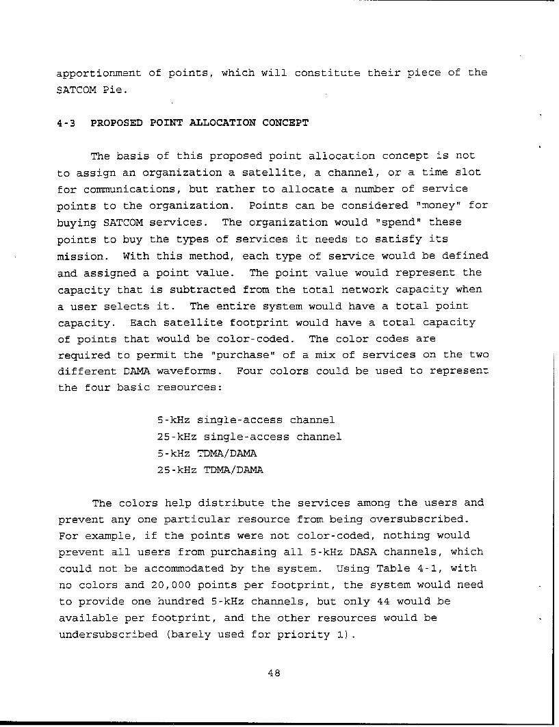
apportionment of points, which will constitute their piece of the
SATCOM Pie.
4-3 PROPOSED POINT ALLOCATION CONCEPT
The basis of this proposed point allocation concept is not
to assign an organization a satellite, a channel, or a time slot
for communications, but rather to allocate a number of service
points to the organization. Points can be considered "money" for
buying SATCOM services. The organization would "spend" these
points to buy the types of services it needs to satisfy its
mission. With this method, each type of service would be defined
and assigned a point value. The point value would represent the
capacity that is subtracted from the total network capacity when
a user selects it. The entire system would have a total point
capacity. Each satellite footprint would have a total capacity
of points that would be color-coded. The color codes are
required to permit the "purchase" of a mix of services on the two
different DAMA waveforms. Four colors could be used to represent
the four basic resources:
5-kHz single-access channel
25-kHz single-access channel
5-kHz TDMA/DAMA
25-kHz TDMA/DAMA
The colors help distribute the services among the users and
prevent any one particular resource from being oversubscribed.
For example, if the points were not color-coded, nothing would
prevent all users from purchasing all 5-kHz DASA channels, which
could not be accommodated by the system. Using Table 4-1, with
no colors and 20,000 points per footprint, the system would need
to provide one hundred 5-kHz channels, but only 44 would be
available per footprint, and the other resources would be
undersubscribed (barely used for priority 1).
48
The total number of points allocated to user organizations
in this footprint cannot exceed the total point capacity, or
services will be oversubscribed. To illustrate, let us assume
that each footprint has 5,000 each of Green, Blue, Yellow, and
Red points. Example point values for the various SATCOM services
are provided in Table 4-1. The numbers in this table are based
on some preliminary calculations as to the relative service
capacities consumed from the total network when each service is
selected.
Table 4-1 Sample Point Allocation Table
SERVICENUMBER UHF SATCOM SERVICE POINTS
1 DASA on 25-kHz channel 500 Green or Blue
2 DASA on 5-kHz channel 200 Green only
3 D o-kbps circuit 350 Green or Blue
4 4.8-kbps circuit 200 Green or Blue5 24.-kbps circuit 200 Greeno Blueo
90 Green, Blue, or5 2.4-kbps circuit Yellow
6 1.2-kbps circuit 60 any color points
7 600-bps circuit 40 any color points
8 300-bps circuit 25 any color points
9 75-bps circuit 15 any color points
10 TDMA/DAMA message service 10 any color points
The table lists the service number, the service offered,
and the point and color value to "buy" that service. Each
organization is allocated a number of colored points. Notice
that some of the services can be bought only with Green points
and others can be bought with any color points. It should also
be noted that the services are not mutually exclusive; that is,
if an organization buys a service, it is entitled access to that
service and all services with an equal or lower point value. The
49
point values represent those required to buy priority 1 service
or "assured access" service.
Points allocated to an organization can be used by that
organization and/or can be allocated to subordinate units for
their use. For example, if an organization were assigned 1,000
Green points, and it decided to use 500 points to give one of 2-s
user nets with 1 DASA 25-kHz channel, that user net would also
entitled access to services 2 through 10.
The organization might also use the remainder of the points
to buy a 1.2-kbps circuit service and a 600-bps circuit service,
and allocate 200 points to each of 2 subordinate units. Many
other combinations of services exist that would add up to 1,000
points. It would depend on the number of user nets that the
organization needed to satisfy, the type of services they
required to complete their missions, and the number of
subordinate units to which they had to allocate SATCOM service.
These nets would all be priority 1 nets and would have assured
access. Other user nets within the organization can be assigned
service at a lower priority, as described below.
To illustrate how precedence and preemption is integrated
into the allocation concept, consider how one of the subordinate
units could use its allocated points. As mentioned earlier,
priority 1 users are those who will have assured access to SATCOM
services. Other users in the unit are assigned lower-priority
levels by taking the number of priority 1 points and applying a
multiplier to calculate the number of points that can be assigned
for that priority level. The multipliers serve two important
purposes: (1) they force users to group their nets into separate
groups with distinct priorities, rather than grouping them all in
one priority, and (2) they allow users to access more expensive
services on a lower-priority basis, which they otherwise would
not be able to afford at all. Below are the multipliers:
50
Priority 1 - 1.00
Priority 2 - 1.25
Priority 3 - 1.50
Priority 4 - 2.50
Priority 5 - 5.00
Using this convention, the unit that was allocated 200
Green points could assign user nets the following configuration:
"* Priority 1 user nets (I x 200 = 200 points)
one 5-kHz DASA channel service (200 points)
"* Priority 2 user nets (1.25 x 200 = 250 points)
two 2.4-kbps circuit service (180 points)
one 600-bps circuit service (40 points)
one 300-bps circuit service (25 points)
"* Priority 3 user nets (1.5 x 200 = 300 points)
two 2.4-kbps circuit service (180 points)
two 1.2-kbps circuit service (120 points)
"• Priority 4 user nets (2.5 x 200 = 500 points)
one 25-kHz DASA channel service (500 points)
"* Priority 5 user nets (5 x 200 = 1000 points)
one 25-kHz DASA channel service (500 points)
four 2.4-kbps circuit service (360 points)
two 1.2-kbps circuit service (120 points)
two 600-bps circuit service (80 points)
This unit can assign 19 nets with SATCOM access, using the
DAMA point allocation method. Under the old single-net-per
channel method, only one net would have access. The DAMA system,
coupled with this point allocation method, allows more users in
this unit to access SATCOM services and still provides the
priority 1 assured access net that would have been allotted under
51
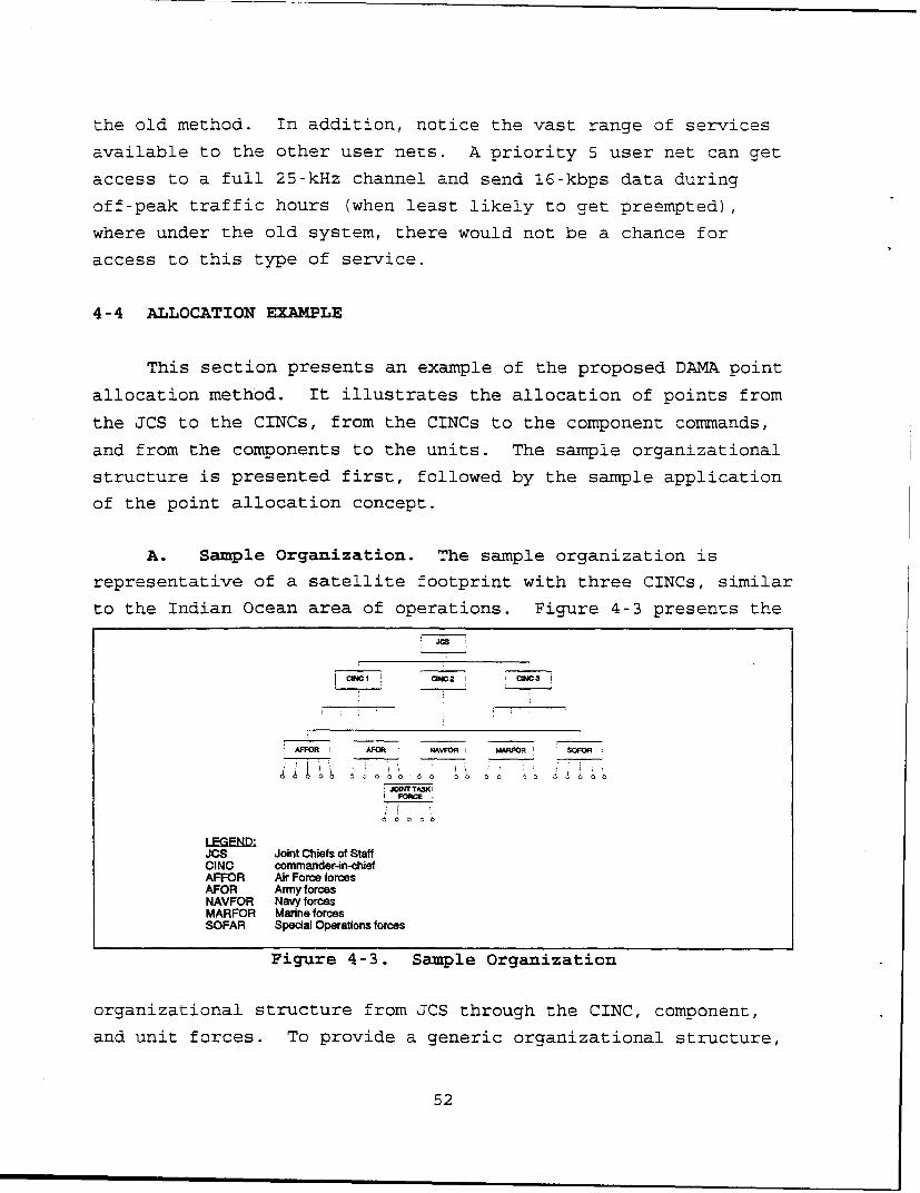
the old method. In addition, notice the vast range of services
available to the other user nets. A priority 5 user net can get
access to a full 25-kHz channel and send 16-kbps data during
off-peak traffic hours (when least likely to get preempted),
where under the old system, there would not be a chance for
access to this type of service.
4-4 ALLOCATION EXAMPLE
This section presents an example of the proposed DAMA point
allocation method. It illustrates the allocation of points from
the JCS to the CINCs, from the CINCs to the component commands,
and from the components to the units. The sample organizational
structure is presented first, followed by the sample application
of the point allocation concept.
A. Sample Organization. The sample organization is
representative of a satellite footprint with three CINCs, similar
to the Indian Ocean area of operations. Figure 4-3 presents the
scs
OINC1 I •ONC2 I CiCS
AFFOR I AFOR NAVFOR I MARFOR I : SOFOR
.660 66 66 8JOHTTASKI
I FORtCE
LEGENDOJCS Joint Chiefs of StaffCINC commander-in-chiefAFFOR Air Force forcesAFOR Army forcesNAVFOR Navy forcesMARFOR Marine forcesSOFAR Special Operations forces
Figure 4-3. Sample Organization
organizational structure from JCS through the CINC, component,
and unit forces. To provide a generic organizational structure,
52
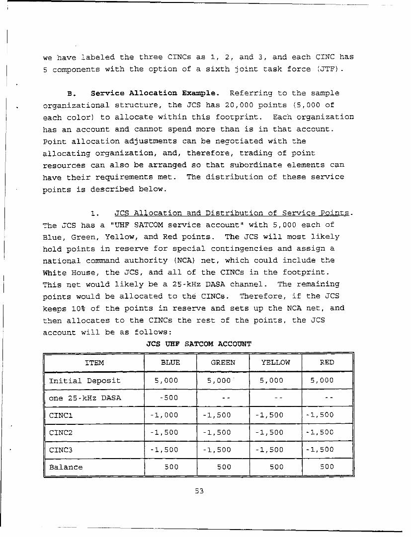
we have labeled the three CINCs as 1, 2, and 3, and each CINC has
5 components with the option of a sixth joint task force (JTF).
B. Service Allocation Example. Referring to the sample
organizational structure, the JCS has 20,000 points (5,000 of
each color) to allocate within this footprint. Each organization
has an account and cannot spend more than is in that account.
Point allocation adjustments can be negotiated with the
allocating organization, and, therefore, trading of point
resources can also be arranged so that subordinate elements can
have their requirements met. The distribution of these service
points is described below.
1. JCS Allocation and Distribution of Service Points.
The JCS has a "UHF SATCOM service account" with 5,000 each of
Blue, Green, Yellow, and Red points. The JCS will most likely
hold points in reserve for special contingencies and assign a
national command authority (NCA) net, which could include the
White House, the JCS, and all of the CINCs in the footprint.
This net would likely be a 25-kHz DASA channel. The remaining
points would be allocated to the CINCs. Therefore, if the JCS
keeps 10% of the points in reserve and sets up the NCA net, and
then allocates to the CINCs the rest of the points, the JCS
account will be as follows:JCS UHF SATCOM ACCOUNT
ITEM BLUE GREEN YELLOW RED
Initial Deposit 5,000 5,000- 5,000 5,000
one 25-kHz DASA -500 -- -- --
CINCI -1,000 -1,500 -1,500 -1,500
CINC2 -1,500 -1,500 -1,500 -1,500
CINC3 -1,500 -1,500 -1,500 -1,500
Balance 500 500 500 500
53
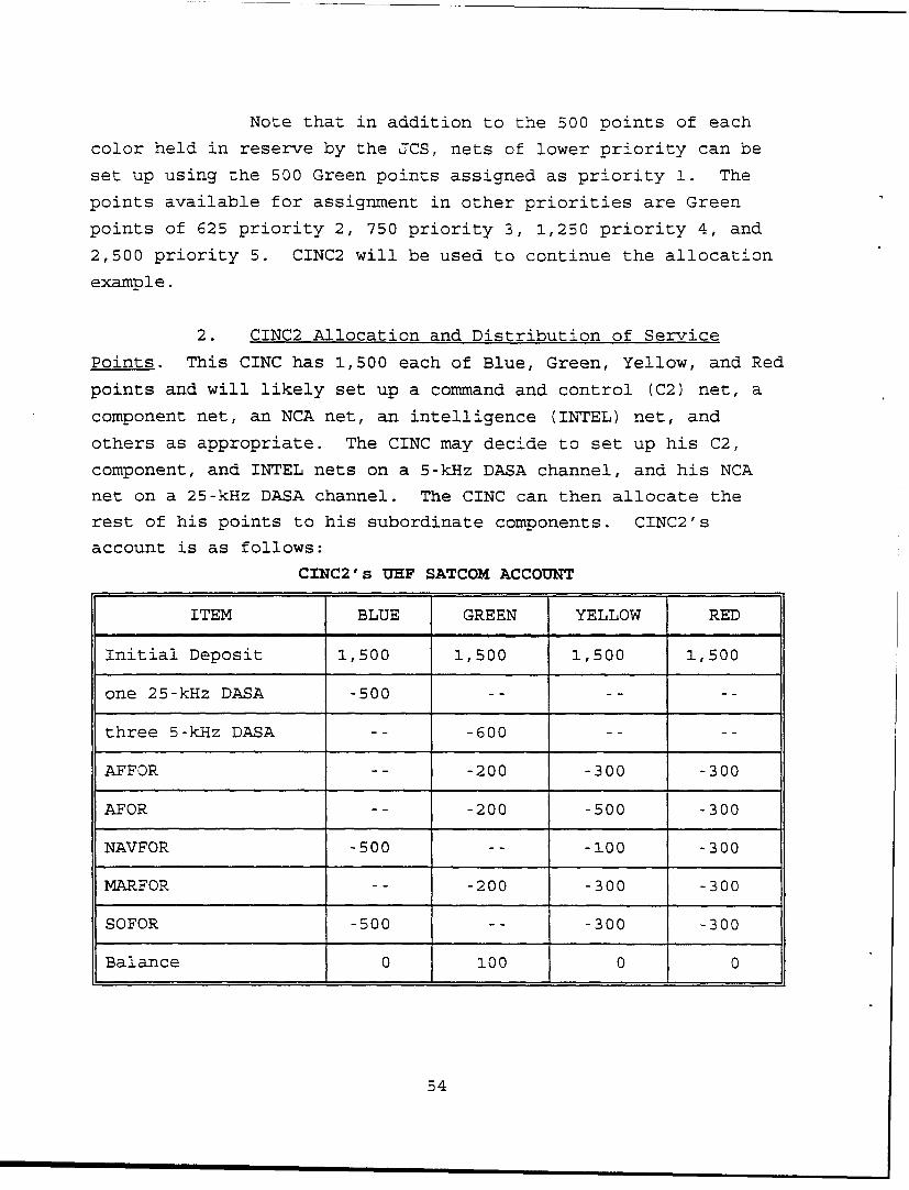
Note that in addition to the 500 points of each
color held in reserve by the JCS, nets of lower priority can be
set up using the 500 Green points assigned as priority 1. The
points available for assignment in other priorities are Green
points of 625 priority 2, 750 priority 3, 1,250 priority 4, and
2,500 priority 5. CINC2 will be used to continue the allocation
example.
2. CINC2 Allocation and Distribution of Service
Points. This CINC has 1,500 each of Blue, Green, Yellow, and Red
points and will likely set up a command and control (C2) net, a
component net, an NCA net, an intelligence (INTEL) net, and
others as appropriate. The CINC may decide to set up his C2,
component, and INTEL nets on a 5-kHz DASA channel, and his NCA
net on a 25-kHz DASA channel. The CINC can then allocate the
rest of his points to his subordinate components. CINC2's
account is as follows:CINC2's UHF SATCOM ACCOUNT
ITEM BLUE GREEN YELLOW RED
Initial Deposit 1,500 1,500 1,500 1,500
one 25-kHz DASA -500 -- -- --
three 5-kHz DASA -- -600 -- --
AFFOR -- -200 -300 -300
AFOR -- -200 -500 -300
NAVFOR -500 -- -100 -300
MARFOR -- -200 -300 -300
SOFOR -500 -- -300 -300
Balance 0 100 0 0
54
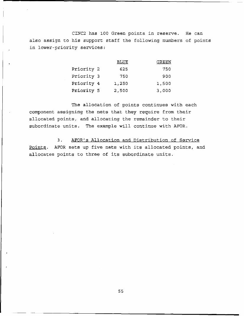
CINC2 has 100 Green points in reserve. He can
also assign to his support staff the following numbers of points
in lower-priority services:
BLUE GREEN
Priority 2 625 750
Priority 3 750 900
Priority 4 1,250 1,500
Priority 5 2,500 3,000
The allocation of points continues with each
component assigning the nets that they require from their
allocated points, and allocating the remainder to their
subordinate units. The example will continue with AFOR.
3. AFOR's Allocation and Distribution of Service
Points. AFOR sets up five nets with its allocated points, and
allocates points to three of its subordinate units.
55
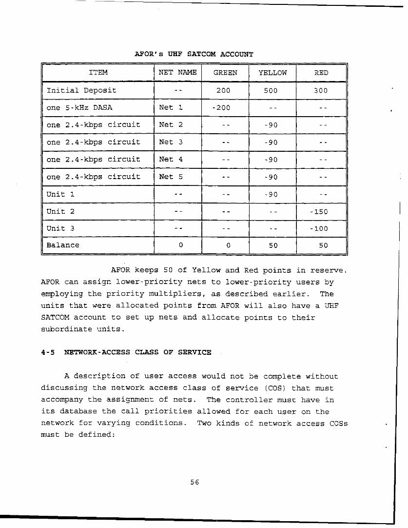
AFOR's UHF SATCOM ACCOUNT
ITEM NET NAME GREEN YELLOW RED
Initial Deposit -- 200 500 300
one 5-kHz DASA Net 1 -200 --
one 2.4-kbps circuit Net 2 -- -90 --
one 2.4-kbps circuit Net 3 -- -90
one 2.4-kbps circuit Net 4 -- -90
one 2.4-kbps circuit Net 5 -- -90
Unit 1 -90
Unit 2 -150
Unit 3 -100
Balance 0 0 50 50
AFOR keeps 50 of Yellow and Red points in reserve.
AFOR can assign lower-priority nets to lower-priority users by
employing the priority multipliers, as described earlier. The
units that were allocated points from AFOR will also have a UHF
SATCOM account to set up nets and allocate points to their
subordinate units.
4-5 NETWORK-ACCESS CLASS OF SERVICE
A description of user access would not be complete without
discussing the network access class of service (COS) that must
accompany the assignment of nets. The controller must have in
its database the call priorities allowed for each user on the
network for varying conditions. Two kinds of network access COSs
must be defined:
56
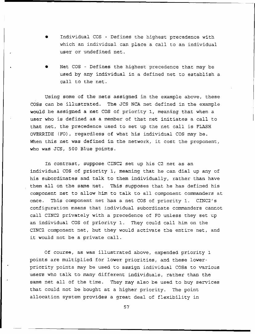
* Individual COS - Defines the highest precedence with
which an individual can place a call to an individual
user or undefined net.
0 Net COS - Defines the highest precedence that may be
used by any individual in a defined net to establish a
call to the net.
Using some of the nets assigned in the example above, these
COSs can be illustrated. The JCS NCA net defined in the example
would be assigned a net COS of priority 1, meaning that when a
user who is defined as a member of that net initiates a call to
that net, the precedence used to set up the net call is FLASH
OVERRIDE (FO), regardless of what his individual COS may be.
When this net was defined in the network, it cost the proponent,
who was JCS, 500 Blue points.
In contrast, suppose CINC2 set up his C2 net as an
individual COS of priority 1, meaning that he can dial up any of
his subordinates and talk to them individually, rather than have
them all on the same net. This supposes that he has defined his
component net to allow him to talk to all component commanders at
once. This component net has a net COS of priority 1. CINC2's
configuration means that individual subordinate commanders cannot
call CINC2 privately with a precedence of FO unless they set up
an individual COS of priority 1. They could call him on the
CINC2 component net, but they would activate the entire net, and
it would not be a private call.
Of course, as was illustrated above, expended priority 1
points are multiplied for lower priorities, and these lower-
priority points may be used to assign individual COSs to various
users who talk to many different individuals, rather than the
same net all of the time. They may also be used to buy services
that could not be bought at a higher priority. The point
allocation system provides a great deal of flexibility in
57
assigning services and satisfying a wide range of user situations
and requirements.
58
APPENDIX A
DELAYS IN WAVEFORM ACQUISITION WITH COLLISIONS
A-I INTRODUCTION
This appendix discusses the time delays experienced when
collisions occur in gaining access to time slots in the TDMA
waveform used for waveform acquisition and the 5-kHz network
login. Based on the a priori knowledge of where the time slots
are located, each earth terminal transmits in one of these time
slots without coordinating with other earth terminals. Without
coordination, two or more earth terminals can experience
collisions. Collisions occur when two or more earth terminals
transmit on the same time slot that is available for access by
any earth terminal. Collisions during terminal set up can be
experienced on the two waveforms as follows:
0 5-kHz. Uplink acquisition (ranging) on the ROW
contention-ranging time slots and login on the
contention ROW message time slots.
0 25-kHz. Uplink acquisition (ranging) on the ranging
time slots.
When collisions occur, procedures are essential to reduce
the possibility of collisions on subsequent retransmissions.
Each terminal waits for some future frame to retransmit; but if
this delay is not random on the part of each terminal, each
retransmits on the first available time slot in the first
available frame, resulting in further collisions. This random
process is discussed for each waveform.
A-1
A-2 5-kHz WAVEFOR ACQUISITION DELAYS WITH COLLISIONS
A. Uplink Acquisition. The 5-kHz waveform has contention-
ranging time slots allocated in the ROW segment of the TDMA
waveform, which are used by terminals to initially enter the DAMA
network. The number of these time slots in each frame is
variable, based on assignment by the DAMA controller. The number
of contention-ranging time slots in each frame can be 1, 2, 4, 8,
12, or 16. Each earth terminal is advised of the number of these
time slots via a field in the FOW. The following explains
actions taken by the terminal from the time the collision is
detected until the follow-on retransmissions are made.
1. The acquisition backoff number is determined based
on whether the transmission is the first or subsequent
retransmission of the ranging signal. The number is 2 for the
initial retransmission and 5, 10, 50, 100, or 250, in the order
shown, for subsequent retransmissions.
2. A uniformly distributed random number between 1
and the acquisition backoff number, inclusive, is generated.
3. At the frame immediately following the first
ranging attempt, the terminal starts counting the number of
contention-ranging time slots that occur.
4. The future frame for retransmission of the ranging
signal is determined when the accumulated number of contention-
ranging time slots equals or exceeds the random number generated
by the terminal.
5. The terminal also generates a uniformly
distributed random number between 1 and the number of contention-
ranging time slots available in the frame determined in 4, above.
A-2
6. The terminal transmits the ranging signal within
the frame determined in 4, above, in the contention-ranging time
slot of that frame equal to the number generated in 5, above.
The delay between the initial transmission and
retransmission is a function of (1) whether the retransmission is
a first or subsequent attempt, which determines the acquisition
backoff number to be used; (2) the random number generated by the
earth terminal, which determines how many contention-ranging time
slots must accrue before retransmission; and (3) the number of
contention-ranging time slots in each frame.
The first retransmission occurs with only a 9-second
delay, regardless of the number of contention-ranging time slots
in each frame. If the random number generated by the terminal is
1, the terminal only has to count 1 contention-ranging time slot
before retransmission. Since the ROW has a minimum of 1 such
slot in each frame, this count is accrued in the next frame. If
the terminal generates 2 as the random number, and there is only
1 contention-ranging time slot in both frames, it retransmits in
the second frame for an 18-second delay. Where there is more
than one contention-ranging time slot in the frame, additional
randomness is provided for by the second number generated by the
terminal, which determines in which time slot the ranging will be
done. If the second transmission experiences a collision, the
terminal increases its backoff number to 5 and repeats the
procedure by selecting a random number between 1 and 5. With
each collision, the backoff number is increased until ranging is
successful.
Table A-1 shows the delays that would be experienced
for each acquisition backoff number, and therefore
retransmissions, assuming a fixed assignment of 1, 8, or 16
contention-ranging time slots per frame. The delays shown are in
seconds and reflect least- and worst-case delays, based on the
earth terminal generated random number. The delays shown in
A-3

Table A-1 do not take into account the actual time slot within
the frame.
Table A-1 Ranging Delays with Collisions
NUMBEROF ACQUISITION BACKOFF NUMBER
CONTENTION-RANGING
TIME SLOTS 5 10 50 100 250PER FRAME 2nd Try 3rd Try 4th Try 5th Try 6th Try
1 18 54 27 135 36 576 45 146 54 370_ 7 8
8 18 18 27 36 36 99 45 211 54 491
16 18 18 27 27 36 63 45 126 54 270
The least delay (left column for each backoff number)
is based on the earth-terminal-generated number that is 1, and
the worst case is an earth-terminal-generated number is equal to
the acquisition backoff number. For example, for a backoff
number of 5, with 1 contention-ranging time slot per frame, the
least delay would occur if the terminal-generated number were 1.
This would result in the subsequent frame selected for
retransmission, or a 9-second delay, added to the delay of 9
seconds for the first failed retry. The worst case would be a
terminal-generated number of 5. This would result in an
additional 4-frame or 36-second delay. Note that regardless of
backoff number, the additional delay is minimal (9 seconds) if
the terminal-generated number is 1. In addition, note that the
number of contention-ranging time slots has a significant effect
on delays.
The worst-case scenario that increases the potential
for collision on the contention-ranging time slots is all
networks attempting to enter the DAMA network following an outage
of the DAMA controller. This potential for collision is
increased if none of the terminals can do passive ranging, all
A-4
terminals have been off the air long enough to lose TDMA
synchronization, and there is urgency in reconstituting networks
to respond to a crisis. To compensate for this condition, the
DAMA controller can increase the number of contention-ranging
time slots per frame. Note also that the random process used,
which is done independently by each earth terminal, enhances the
probability that collisions will not occur.
B. Login Delays with Collision. A terminal assumes that
a transmitted login request was lost by the DAMA controller if an
acknowledgment is not received within 4 frames (36 seconds).
Should this occur, the terminal automatically retransmits the
login request after a random delay. The number of contention ROW
time slots in each frame used for forwarding login requests is
variable, based on DAMA controller assignments. Each terminal
must determine the number of these time slots from information in
the FOW segment. The following describes the steps taken between
the time a collision is experienced and the time the login
request is retransmitted:
1. The terminal looks up the ROW contention backoff
number provided by the DAMA controller in the FOW. This backoff
number can be 1, 30, 60, 250, or 1,000.
2. A uniformly distributed random number between 1
and the backoff number, inclusive, is generated.
3. Starting at the next frame, the number of
contention ROW time slots is counted.
4. In the frame where the accumulated number of
contention ROW time slots equals or exceeds the random number
generated in (2) above, the retransmission is made.
A-5

5. Another random number between 1 and the number of
ROW contention-ranging time slots in the frame determined in (4),
above, is generated.
6. In the frame determined in (4), above, the
terminal retransmits the login request in the time slot
determined in (5), above.
The delay between initial transmission of a login
message and subsequent retransmission is a function of (1) the
contention ROW backoff number; (2) the terminal-generated random
number; and (3) the number of contention ROW time slots per
frame, which is variable frame-to-frame, based on DAMA controller
assignments.
Table A-2 lists the delays experienced in automatically
retransmitting a login message. The delays shown do not reflect
the 36-second delay between transmission of the initial login
request and lack of receipt an acknowledgment within 4 frames.
Table A-2 lists delays for each contention ROW backoff number and
gives the best- and worst-case delay for when there are 5 or 11
contention ROW time slots per frame. The best case applies when
the earth-terminal-generated random number is 1. The worst case
is when the earth terminal generates a random number equal to the
backoff number. For example, the best-case delay for a backoff
number of 60, assuming there are 5 contention ROW time slots per
frame, is 9 seconds. This is based on the terminal's generating
a random number of 1. In this situation, the retransmission
occurs in the frame following initial transmission. The worst
case is based on the terminal's generating a random number of 60.
In this case, the delay is 108 seconds.
A-6
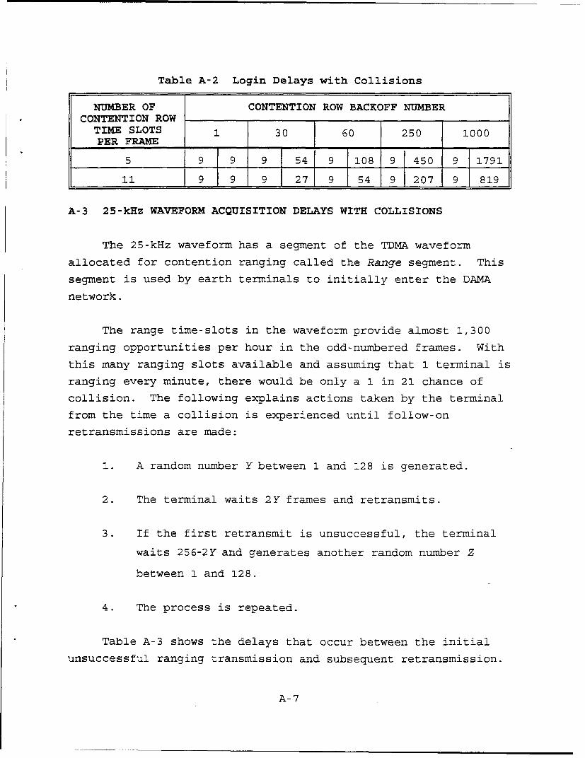
Table A-2 Login Delays with Collisions
NUMBER OF CONTENTION ROW BACKOFF NUMBERCONTENTION ROW
TIME SLOTS 1 30 60 250 1000PER FRAME
5 9 9 9 54 9 108 9 450 9 1791
11 9 9 9 27 9 54 9 207 9 819
A-3 25-kHz WAVEFORM ACQUISITION DELAYS WITH COLLISIONS
The 25-kHz waveform has a segment of the TDMA waveform
allocated for contention ranging called the Range segment. This
segment is used by earth terminals to initially enter the DAMA
network.
The range time-slots in the waveform provide almost 1,300
ranging opportunities per hour in the odd-numbered frames. With
this many ranging slots available and assuming that 1 terminal is
ranging every minute, there would be only a 1 in 21 chance of
collision. The following explains actions taken by the terminal
from the time a collision is experienced until follow-on
retransmissions are made:
1. A random number Y between 1 and 128 is generated.
2. The terminal waits 2Y frames and retransmits.
3. If the first retransmit is unsuccessful, the terminal
waits 256-2Y and generates another random number Z
between 1 and 128.
4. The process is repeated.
Table A-3 shows the delays that occur between the initial
unsuccessful ranging transmission and subsequent retransmission.
A-7
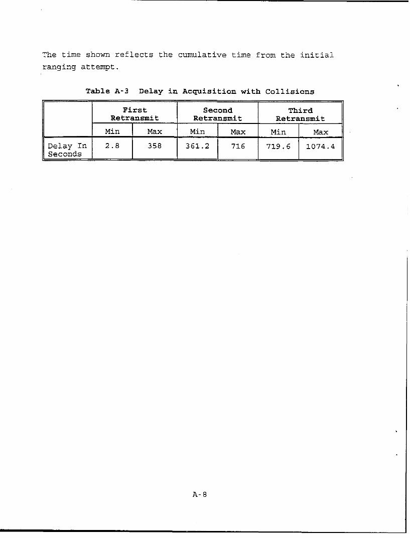
The time shown reflects the cumulative time from the initial
ranging attempt.
Table A-3 Delay in Acquisition with Collisions
First Second Third
Retransmit Retransmit Retransmit
Min Max Min Max Min Max
Delay In 2.8 358 361.2 716 719.6 1074.4Seconds
A-8
APPENDIX B
DELAYS IN SERVICE REQUEST RESPONSE WITH COLLISIONS
B-. INTRODUCTION
This appendix discusses the delays experienced in gaining
access to time slots in the TDMA waveform used to forward service
requests from the terminal to the DAMA controller. Based on
a priori knowledge of where these time slots are located, each
earth terminal selects and transmits on a specific time slot
without coordinating with other earth terminals. Without this
coordination the service request can be lost due to collisions.
Collisions occur when two or more earth terminals transmit in the
same time slot that is available for access by any earth
terminal. Should this message loss occur, procedures are
essential to reduce the possibility of collisions on subsequent
transmissions of the service request. Each terminal waits for
some future frame to retransmit, but if the delay is not random
on the part of each terminal, each transmits on the first
available time slot in the first available frame. Again, the
requests are lost. The manner in which the earth terminals
manage these random retransmissions is discussed for each
waveform.
B-2 5-kHz LINK SET-UP DELAYS WITH COLLISIONS
A terminal assumes that a transmitted service request was
lost by the DAMA controller if an acknowledgment is not received
within 4 frames (36 seconds). Should this occur, the terminal
automatically retransmits one service request after a random
delay. The number of contention ROW time slots in each frame
used for forwarding service requests is variable, based on DAMA
controller assignments. Each terminal is advised of the number
and location of these time slots via an FOW message. The
following describes the steps taken between the time a collision
B-1
occurs and the time the service request is automatically
retransmitted:
A. The earth terminal looks up the ROW contention
backoff number provided by the DAMA controller in the FOW. This
backoff number can be 1, 30, 60, 250, or 1,000.
B. A uniformly distributed random number between 1
and the backoff number, inclusive, is generated.
C. Starting at the next frame, the number of
contention ROW time slots is counted.
D. At the point where the number of contention ROW
time slots equals or exceeds the random number generated in B,
above, is the frame used for retransmission.
E. Another random number between 1 and the number of
ROW contention time slots in the frame determined in D, above, is
generated.
F. In the frame determined in D, above, the terminal
retransmits the service request in the time slot determined in E,
above.
The delay between initial transmission of a service request
message and subsequent retransmission is a function of (1) the
contention ROW backoff number; (2) the terminal-generated random
number; and (3) the number of contention ROW time slots per
frame, which is variable frame-to-frame, based on DAMA controller
assignments.
Table B-1 lists the delays experienced in the automatic
retransmission of one additional service request message, based
on the ROW backoff number and the number of contention ROW time
slots. This table lists delays for each contention ROW backoff
B-2
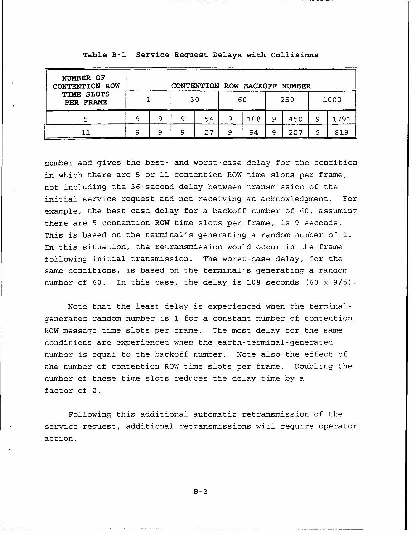
Table B-I Service Request Delays with Collisions
NUMBER OFCONTENTION ROW CONTENTION ROW BACKOFF NUMBER
TIME SLOTSPER FRAME 1 30 60 250 1000
5 9 9 9 54 9 108 9 450 9 1791
11 9 9 9 27 9 54 9 207 9 819
number and gives the best- and worst-case delay for the condition
in which there are 5 or 11 contention ROW time slots per frame,
not including the 36-second delay between transmission of the
initial service request and not receiving an acknowledgment. For
example, the best-case delay for a backoff number of 60, assuming
there are 5 contention ROW time slots per frame, is 9 seconds.
This is based on the terminal's generating a random number of 1.
In this situation, the retransmission would occur in the frame
following initial transmission. The worst-case delay, for the
same conditions, is based on the terminal's generating a random
number of 60. In this case, the delay is 108 seconds (60 x 9/5).
Note that the least delay is experienced when the terminal-
generated random number is 1 for a constant number of contention
ROW message time slots per frame. The most delay for the same
conditions are experienced when the earth-terminal-generated
number is equal to the backoff number. Note also the effect of
the number of contention ROW time slots per frame. Doubling the
number of these time slots reduces the delay time by a
factor of 2.
Following this additional automatic retransmission of the
service request, additional retransmissions will require operator
action.
B-3
B-3 25-kHz LINK SET-UP DELAYS
The information presented in this section is based on an
interpretation of paragraph 5.2.2.3.3 of MIL-STD 188-183. This
section should be reviewed thoroughly to clarify the procedures
contained therein. The procedure for initial RCCOW transmission,
as well as the number of retransmission attempts, are only two of
the items requiring clarification. Others include the selection
of random wait times and the specific reasons for the wait times
specified.
A terminal assumes that an RCCOW service request was lost by
the DAMA controller, if a CCOW Acknowledgment message is not
received within three frames or 4.2 seconds. When this happens,
the terminal selects a random number between 1 and 20 and waits
that number of frames before continuing with the procedures
below. The RCCOW is automatically retransmitted once. Further
retransmissions require the service request to be reentered. The
delay in retransmission is a function of the precedence of the
RCCOW and the frame used in the initial transmission of the
service request. General frame precedence is established by the
DAMA controller and forwarded to all terminals in the Precedence
Cutoff field of the master frame and in the RCCOW Assignment
field of the CCOW. Additional automatic retransmission of the
service request is based on the following:
A. Frame and Initial RCCOW Precedence Equal. If the frame
and service request precedence were equal for the initial
transmission, after the random wait described above, the request
is retransmitted in the next frame where the frame precedence is
equal to or greater than the service request precedence.
B. Initial RCCOW Precedence Greater Than Frame. If the
service request precedence was greater than the frame precedence
for the initial service request, after waiting the random number
of frames described above, the next 8 frames are checked. If a
B-4
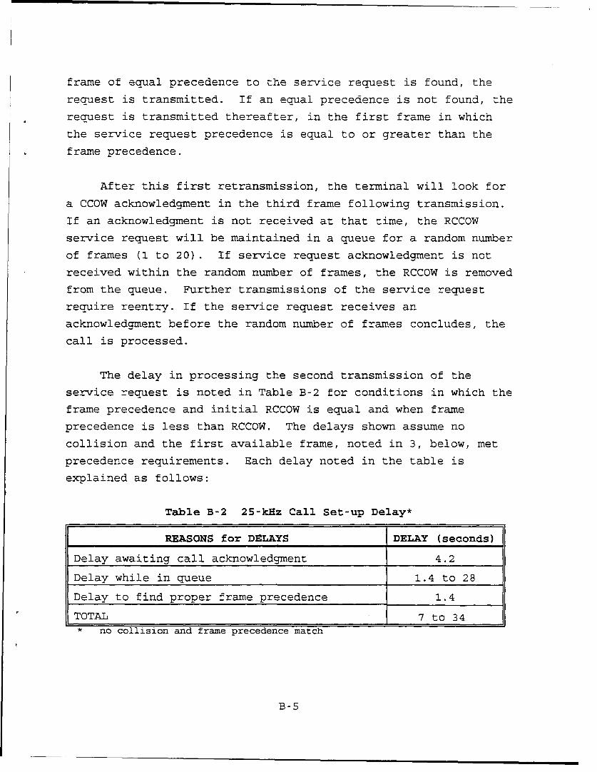
frame of equal precedence to the service request is found, the
request is transmitted. If an equal precedence is not found, the
request is transmitted thereafter, in the first frame in which
the service request precedence is equal to or greater than the
frame precedence.
After this first retransmission, the terminal will look for
a CCOW acknowledgment in the third frame following transmission.
If an acknowledgment is not received at that time, the RCCOW
service request will be maintained in a queue for a random number
of frames (1 to 20). If service request acknowledgment is not
received within the random number of frames, the RCCOW is removed
from the queue. Further transmissions of the service request
require reentry. If the service request receives an
acknowledgment before the random number of frames concludes, the
call is processed.
The delay in processing the second transmission of the
service request is noted in Table B-2 for conditions in which the
frame precedence and initial RCCOW is equal and when frame
precedence is less than RCCOW. The delays shown assume no
collision and the first available frame, noted in 3, below, met
precedence requirements. Each delay noted in the table is
explained as follows:
Table B-2 25-kHz Call Set-up Delay*
REASONS for DELAYS DELAY (seconds)
Delay awaiting call acknowledgment 4.2
Delay while in queue 1.4 to 28
Delay to find proper frame precedence 1.4
TOTAL 7 to 34* no collision and frame precedence match
B-5
1. A 3-frame delay before the terminal notes that a
call acknowledgment was not received and assumes that the service
request was lost, or 4.2 seconds.
2. A delay of 1.4 to 28 seconds for the time the
initial service request is maintained in a queue following the
point that call acknowledgment should have been received. It is
at the completion of this time that the terminal takes action to
retransmit.
3. A delay of 1.4 seconds awaiting next frame. Note
that this assumes the next frame has a precedence equal to the
call precedence. Additional delays could be experienced if there
is not a match.
B-6
APPENDIX C
REFERENCES
The following references were used in the preparation of
this tutorial:
A. MIL-STD-188-181, Interoperability Standard for
Dedicated 5-kHz and 25-kHz UHF Satellite Communications
Channels, 18 September 1992
B. MIL-STD-188-182, Interoperability Standard for 5-kHz
UHF DAMA Terminal Waveform, 18 September 1992
C. MIL-STD-188-183, Interoperability Standard for 25-kHz
UHF TDMA/DAMA Terminal Waveform, 18 September 1992
D. JTC3A Report 9300, Tutorial on Satellite Communications
with Emphasis on UHF TDMA/DAMA Systems, Draft,
31 October 1991
E. JTC3A Final Report, Benefits of 25 kHz TDMA/DAMA for
UHF Satellite Communications, 8 March 1992
F. DISA/JIE0 CFS Briefing and Report, UHF SATCOM DAMA
Principles and Assessments of UHF DAMA Management and
Control
G. Joint Staff Memorandum, Subject: Tasking Based on
MILSATCOM Users Conference 93-1, dated
10 September 1993.
H. Joint UHF SATCOM DAMA Concept of Operations (CONOPS)
C-1


![Đồng Nai Province Documents/Duthao... · 90 dtúng cíc phðngî ban thJôc ca tô chúCî don IPh6 (Yim CfJng an tinh ]Phó Trilånv Iban An sc chuyen tj£ch ]Ban An to)n Jieo](https://img.pdfslide.net/doc/110x75/608e19f6f011e840a63e28b2/ng-nai-province-documentsduthao-90-dtng-cc-phng-ban-thjc-ca.jpg)