Embed Size (px)
Citation preview
Tutorial for TestConductor for RiJ
RiJ Tutorialfor
IBM® Rational® Rhapsody® TestConductor Add On
2
License Agreement No part of this publication may be reproduced, transmitted, stored in a retrieval system, nor translated into any human or computer language, in any form or by any means, electronic, mechanical, magnetic, optical, chemical, manual or otherwise, without the prior written permission of the copyright owner, BTC Embedded Systems AG.
The information in this publication is subject to change without notice, and BTC Embedded Systems AG assumes no responsibility for any errors which may appear herein. No warranties, either expressed or implied, are made regarding Rhapsody software including documentation and its fitness for any particular purpose. Trademarks
IBM® Rational® Rhapsody®, IBM® Rational® Rhapsody®
Automatic Test Generation Add On, and IBM® Rational®
Rhapsody® TestConductor Add On are registered trademarks of IBM Corporation. All other product or company names mentioned herein may be trademarks or registered trademarks of their respective owners. © Copyright 2000-2014 BTC Embedded Systems AG. All rights reserved.
3
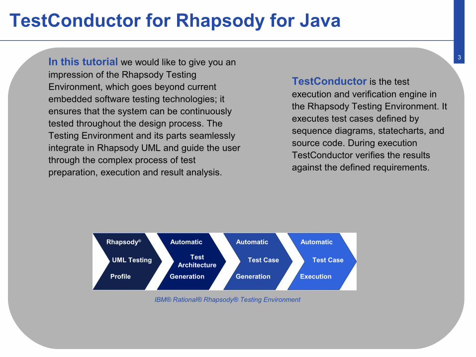
TestConductor is the test execution and verification engine in the Rhapsody Testing Environment. It executes test cases defined by sequence diagrams, statecharts, and source code. During execution TestConductor verifies the results against the defined requirements.
In this tutorial we would like to give you an impression of the Rhapsody Testing Environment, which goes beyond current embedded software testing technologies; it ensures that the system can be continuously tested throughout the design process. The Testing Environment and its parts seamlessly integrate in Rhapsody UML and guide the user through the complex process of test preparation, execution and result analysis.
TestConductor for Rhapsody for Java
IBM® Rational® Rhapsody® Testing Environment
Rhapsody®
UML Testing
Profile
Automatic
TestArchitecture
Generation
Automatic
Test Case
Generation
Automatic
Test Case
Execution
4
StopWatch Application
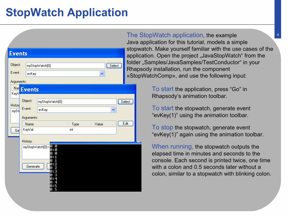
To start the application, press “Go” inRhapsody’s animation toolbar.
To start the stopwatch, generate event“evKey(1)” using the animation toolbar.
To stop the stopwatch, generate event“evKey(1)” again using the animation toolbar.
When running, the stopwatch outputs theelapsed time in minutes and seconds to the console. Each second is printed twice, one timewith a colon and 0.5 seconds later without a colon, similar to a stopwatch with blinking colon.
The StopWatch application, the exampleJava application for this tutorial, models a simple stopwatch. Make yourself familiar with the use cases of the application. Open the project „JavaStopWatch“ from the folder „Samples/JavaSamples/TestConductor“ in your Rhapsody installation, run the component «StopWatchComp», and use the following input:
5
StopWatch Model
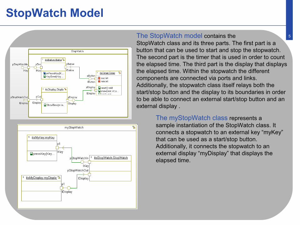
The myStopWatch class represents a sample instantiation of the StopWatch class. It connects a stopwatch to an external key “myKey” that can be used as a start/stop button. Additionally, it connects the stopwatch to an external display “myDisplay” that displays the elapsed time.
The StopWatch model contains theStopWatch class and its three parts. The first part is a button that can be used to start and stop the stopwatch.The second part is the timer that is used in order to countthe elapsed time. The third part is the display that displaysthe elapsed time. Within the stopwatch the differentcomponents are connected via ports and links. Additionally, the stopwatch class itself relays both the start/stop button and the display to its boundaries in order to be able to connect an external start/stop button and an external display .
6
System Under Test
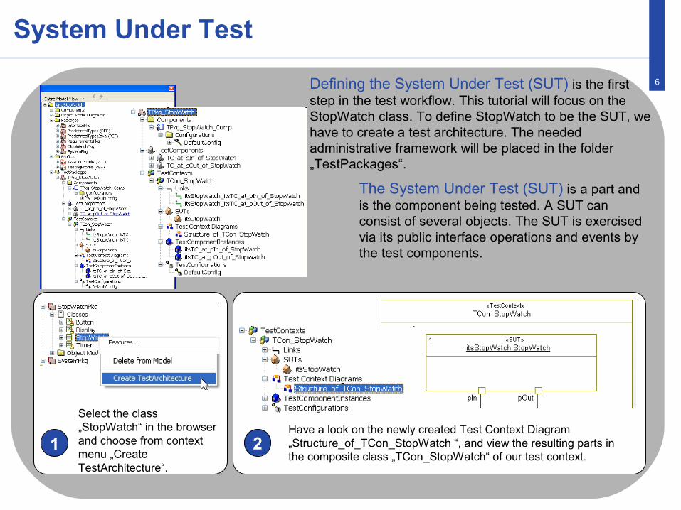
The System Under Test (SUT) is a part and is the component being tested. A SUT can consist of several objects. The SUT is exercised via its public interface operations and events by the test components.
Defining the System Under Test (SUT) is the first step in the test workflow. This tutorial will focus on the StopWatch class. To define StopWatch to be the SUT, we have to create a test architecture. The needed administrative framework will be placed in the folder „TestPackages“.
1 2
Select the class „StopWatch“ in the browser and choose from context menu „Create TestArchitecture“.
Have a look on the newly created Test Context Diagram „Structure_of_TCon_StopWatch “, and view the resulting parts in the composite class „TCon_StopWatch“ of our test context.
7
Test Architecture
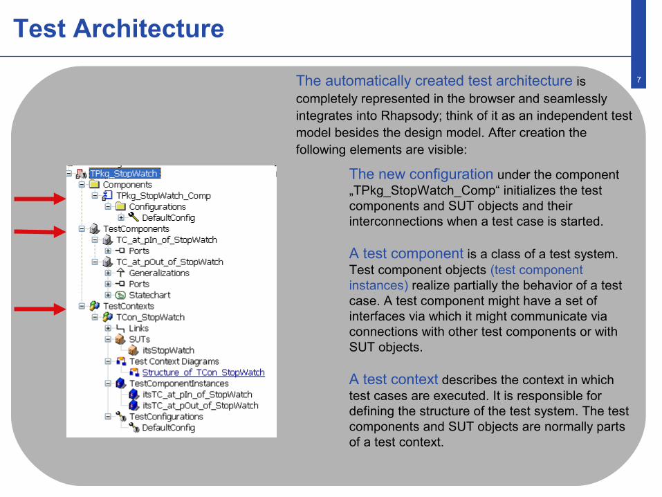
The new configuration under the component „TPkg_StopWatch_Comp“ initializes the test components and SUT objects and their interconnections when a test case is started.
A test component is a class of a test system. Test component objects (test component instances) realize partially the behavior of a test case. A test component might have a set of interfaces via which it might communicate via connections with other test components or with SUT objects.
A test context describes the context in which test cases are executed. It is responsible for defining the structure of the test system. The test components and SUT objects are normally parts of a test context.
The automatically created test architecture is completely represented in the browser and seamlessly integrates into Rhapsody; think of it as an independent test model besides the design model. After creation the following elements are visible:
8
Test Context
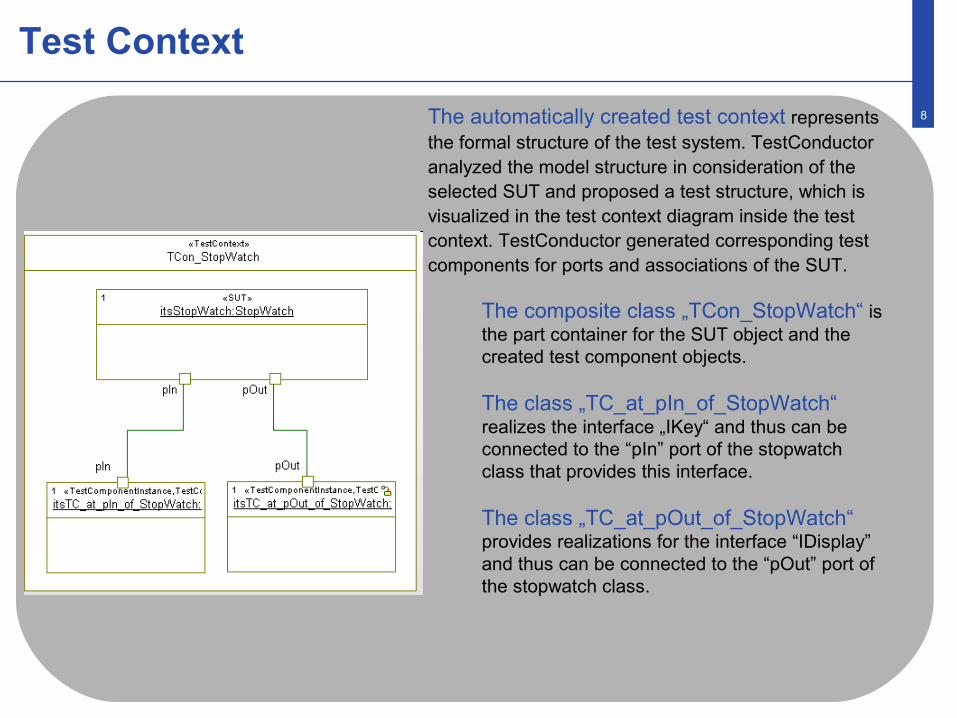
The composite class „TCon_StopWatch“ is the part container for the SUT object and the created test component objects.
The class „TC_at_pIn_of_StopWatch“ realizes the interface „IKey“ and thus can be connected to the “pIn” port of the stopwatch class that provides this interface.
The class „TC_at_pOut_of_StopWatch“ provides realizations for the interface “IDisplay” and thus can be connected to the “pOut” port of the stopwatch class.
The automatically created test context represents the formal structure of the test system. TestConductor analyzed the model structure in consideration of the selected SUT and proposed a test structure, which is visualized in the test context diagram inside the test context. TestConductor generated corresponding test components for ports and associations of the SUT.
9
Adjusting Test Architecture
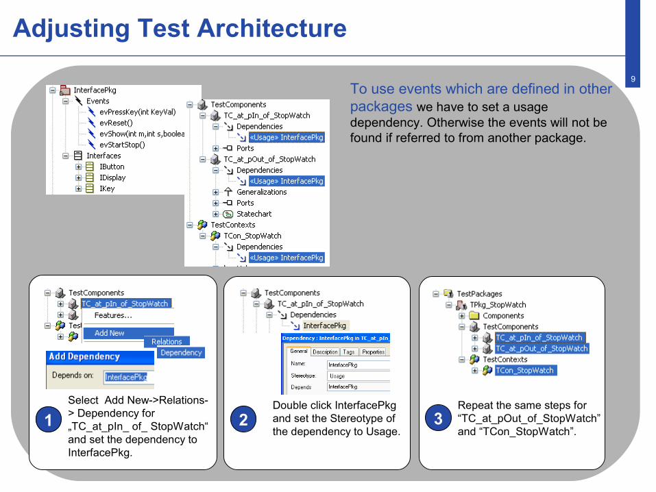
To use events which are defined in other packages we have to set a usage dependency. Otherwise the events will not be found if referred to from another package.
1 2 3Select Add New->Relations-> Dependency for „TC_at_pIn_ of_ StopWatch“ and set the dependency to InterfacePkg.
Double click InterfacePkg and set the Stereotype of the dependency to Usage.
Repeat the same steps for “TC_at_pOut_of_StopWatch” and “TCon_StopWatch”.
10
Test Cases
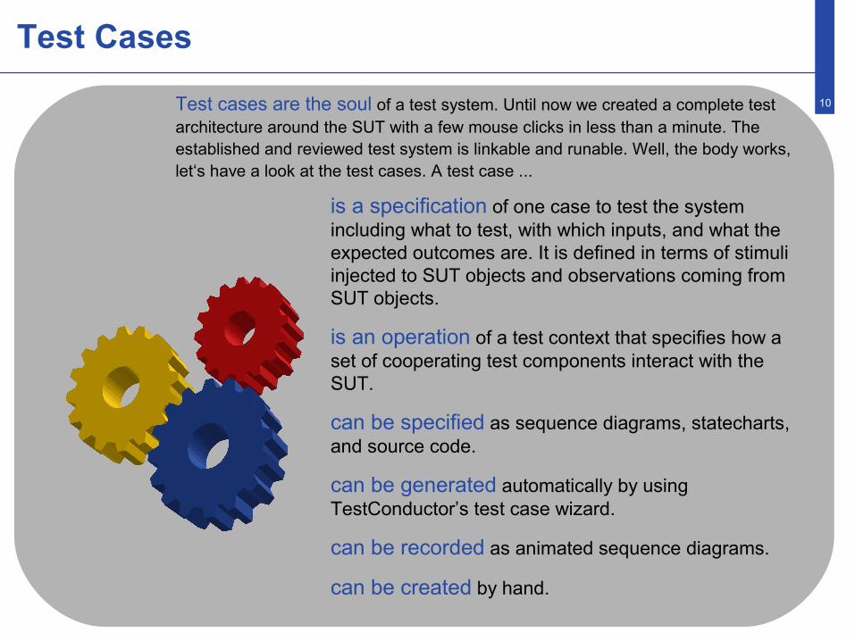
is a specification of one case to test the system including what to test, with which inputs, and what the expected outcomes are. It is defined in terms of stimuli injected to SUT objects and observations coming from SUT objects.
is an operation of a test context that specifies how a set of cooperating test components interact with the SUT.
can be specified as sequence diagrams, statecharts, and source code.
can be generated automatically by using TestConductor’s test case wizard.
can be recorded as animated sequence diagrams.
can be created by hand.
Test cases are the soul of a test system. Until now we created a complete test architecture around the SUT with a few mouse clicks in less than a minute. The established and reviewed test system is linkable and runable. Well, the body works, let‘s have a look at the test cases. A test case ...
11
Test Case Specification
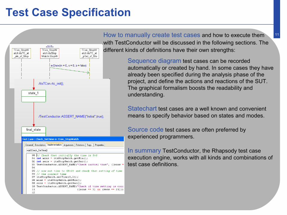
Sequence diagram test cases can be recorded automatically or created by hand. In some cases they have already been specified during the analysis phase of the project, and define the actions and reactions of the SUT. The graphical formalism boosts the readability and understanding.
Statechart test cases are a well known and convenient means to specify behavior based on states and modes.
Source code test cases are often preferred by experienced programmers.
In summary TestConductor, the Rhapsody test case execution engine, works with all kinds and combinations of test case definitions.
How to manually create test cases and how to execute them with TestConductor will be discussed in the following sections. The different kinds of definitions have their own strengths:
12
Test Case: Sequence Diagram I
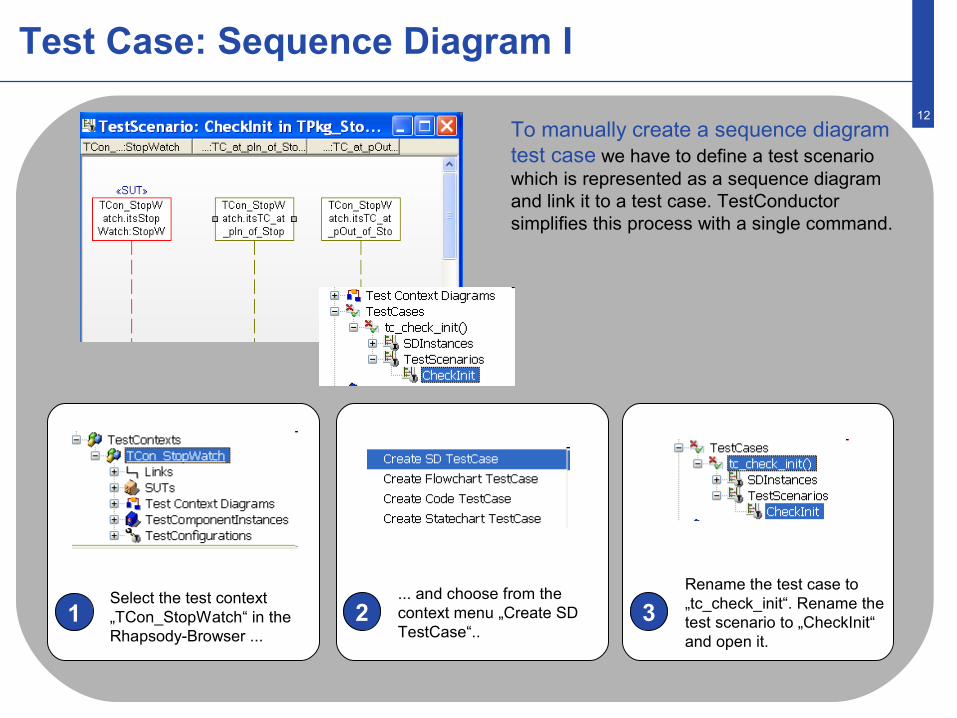
To manually create a sequence diagramtest case we have to define a test scenario which is represented as a sequence diagramand link it to a test case. TestConductor simplifies this process with a single command.
1 2 3Select the test context „TCon_StopWatch“ in the Rhapsody-Browser ...
... and choose from the context menu „Create SD TestCase“..
Rename the test case to „tc_check_init“. Rename the test scenario to „CheckInit“ and open it.
13
Test Case: Sequence Diagram II
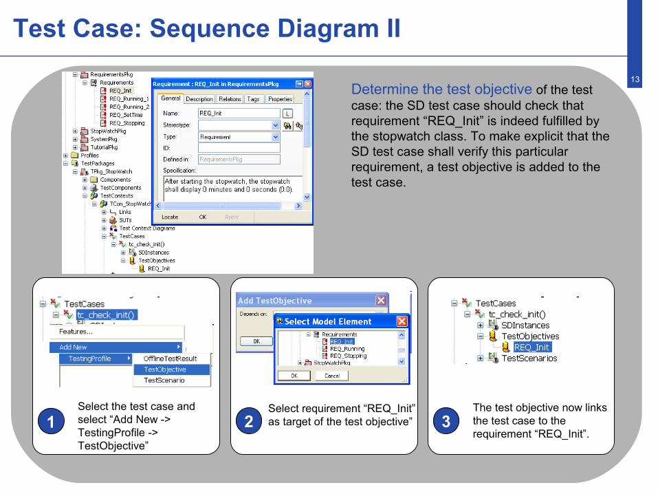
Determine the test objective of the test case: the SD test case should check that requirement “REQ_Init” is indeed fulfilled by the stopwatch class. To make explicit that the SD test case shall verify this particular requirement, a test objective is added to the test case.
1 2 3Select the test case and select “Add New -> TestingProfile -> TestObjective”
Select requirement “REQ_Init” as target of the test objective”
The test objective now links the test case to the requirement “REQ_Init”.
14
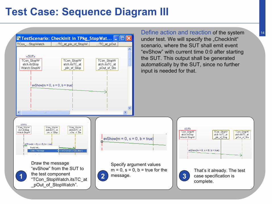
Test Case: Sequence Diagram III
Define action and reaction of the system under test. We will specify the „CheckInit“ scenario, where the SUT shall emit event “evShow” with current time 0:0 after starting the SUT. This output shall be generated automatically by the SUT, since no further input is needed for that.
1 2 3
Draw the message “evShow” from the SUT to the test component “TCon_StopWatch.itsTC_at_pOut_of_StopWatch”.
Specify argument values m = 0, s = 0, b = true for the message.
That’s it already. The test case specification is complete.
15
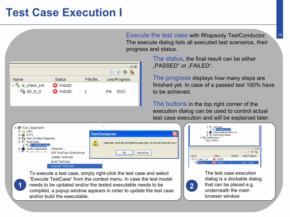
Test Case Execution I
The status, the final result can be either „PASSED“ or „FAILED“.
The progress displays how many steps are finished yet. In case of a passed test 100% have to be achieved.
The buttons in the top right corner of the execution dialog can be used to control actual test case execution and will be explained later.
Execute the test case with Rhapsody TestConductor.The execute dialog lists all executed test scenarios, their progress and status.
1 2
To execute a test case, simply right-click the test case and select “Execute TestCase” from the context menu. In case the test model needs to be updated and/or the tested executable needs to be compiled, a popup window appears in order to update the test case and/or build the executable.
The test case execution dialog is a dockable dialog that can be placed e.g. underneath the main browser window

16
Test Case Execution II
1 2 3
To open the debug sequence diagram right click the item SD_tc_0 in the TestConductor execution dialog…
... and select “Show as SD”In the browser, underneath the test case, you can find the generated html report. Double click the report to open it.
The test case execution FAILED with Rhapsody TestConductor. To analyze the reason TestConductor offers two kind of views. The HTML-report displays a textual summary and can be found directly under the test case in the Rhapsody-Browser. TestConductor created a debug sequence diagram to display the error. The red arrow visualizes the faulty step and the reason. TestConductor expects the parameter value „true“ for argument “b”, but observes the value „false“ during actual test execution. The expected value was not specified correctly... by accident.
17
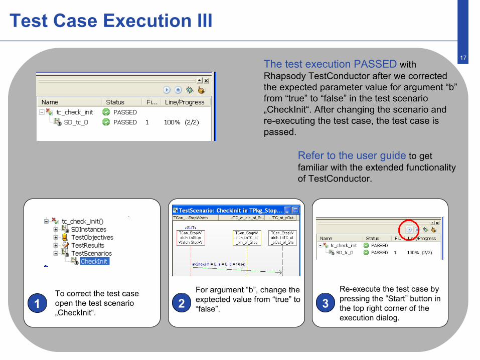
Test Case Execution III
Refer to the user guide to get familiar with the extended functionality of TestConductor.
1 2 3To correct the test case open the test scenario „CheckInit“.
For argument “b”, change the exptected value from “true” to “false”.
Re-execute the test case by pressing the “Start” button in the top right corner of the execution dialog.
The test execution PASSED with Rhapsody TestConductor after we corrected the expected parameter value for argument “b” from “true” to “false” in the test scenario „CheckInit“. After changing the scenario and re-executing the test case, the test case is passed.
18
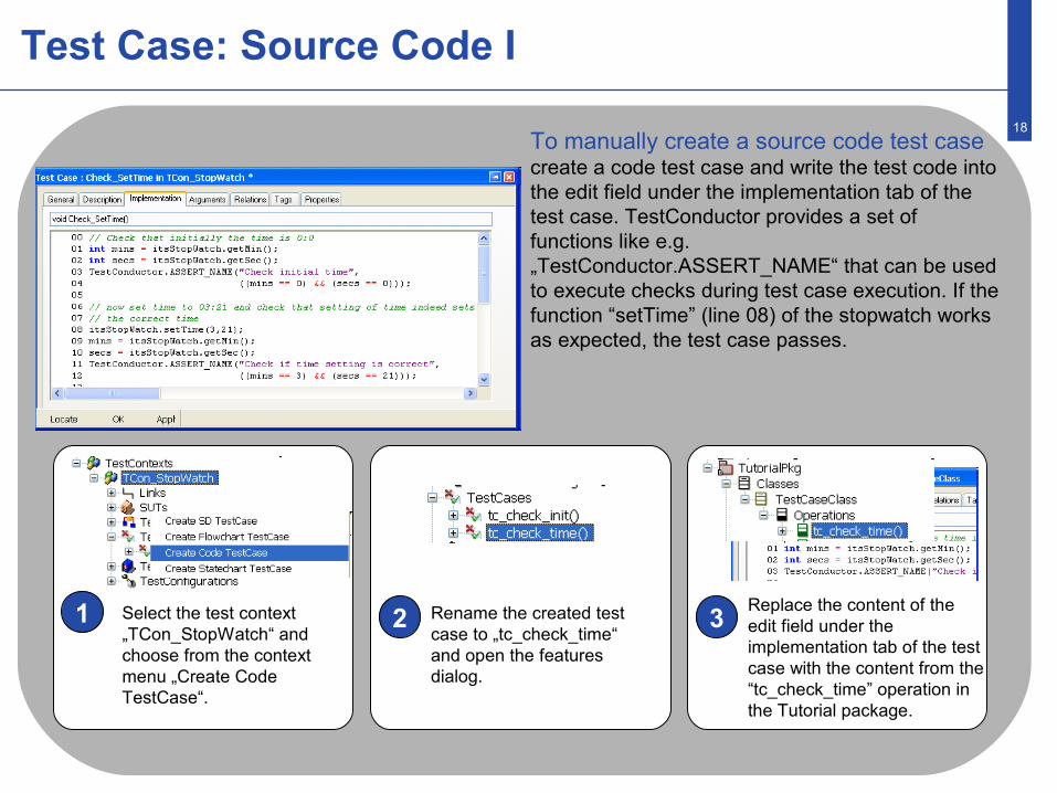
Test Case: Source Code I
1 2 3Select the test context „TCon_StopWatch“ and choose from the context menu „Create Code TestCase“.
Rename the created test case to „tc_check_time“ and open the features dialog.
Replace the content of the edit field under the implementation tab of the test case with the content from the “tc_check_time” operation in the Tutorial package.
To manually create a source code test case create a code test case and write the test code into the edit field under the implementation tab of the test case. TestConductor provides a set of functions like e.g. „TestConductor.ASSERT_NAME“ that can be used to execute checks during test case execution. If the function “setTime” (line 08) of the stopwatch works as expected, the test case passes.
19
Source Code Test Case: Execution
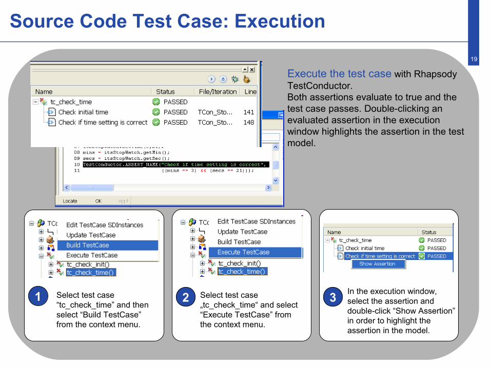
1 2 3Select test case “tc_check_time” and then select “Build TestCase” from the context menu.
Select test case „tc_check_time“ and select “Execute TestCase” from the context menu.
In the execution window, select the assertion and double-click “Show Assertion” in order to highlight the assertion in the model.
Execute the test case with Rhapsody TestConductor.Both assertions evaluate to true and the test case passes. Double-clicking an evaluated assertion in the execution window highlights the assertion in the test model.

20
Test Case: Statecharts I
1 2 3Select the test context „TCon_StopWatch“ and select “Create Statechart TestCase”.
Rename the test case to “tc_check_progress”
To manually create a statechart test case we have to define a test scenario which is represented as a statechart and link it to a test case. Technically, the test case has a dependency to a TestComponent that contains the statechart. TestConductor simplifies this process with a single command.
Add a test objective (using “Add New -> TestingProfile ->TestObjective”) to requirement REQ_Running_1
21
Test Case: Statecharts II
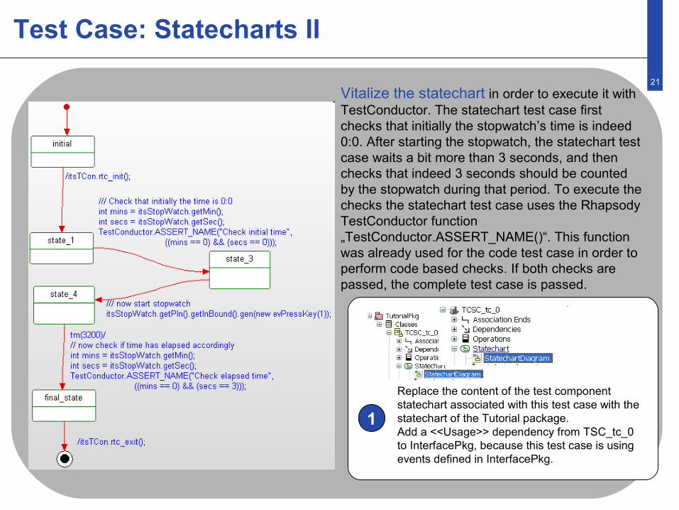
Replace the content of the test component statechart associated with this test case with the statechart of the Tutorial package.Add a <<Usage>> dependency from TSC_tc_0 to InterfacePkg, because this test case is using events defined in InterfacePkg.
Vitalize the statechart in order to execute it with TestConductor. The statechart test case first checks that initially the stopwatch’s time is indeed 0:0. After starting the stopwatch, the statechart test case waits a bit more than 3 seconds, and then checks that indeed 3 seconds should be counted by the stopwatch during that period. To execute the checks the statechart test case uses the Rhapsody TestConductor function „TestConductor.ASSERT_NAME()“. This function was already used for the code test case in order to perform code based checks. If both checks are passed, the complete test case is passed.
1
22
Statechart Test Execution
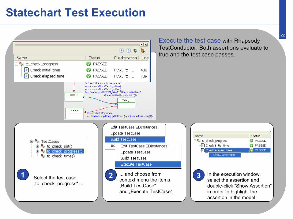
1 2 3Select the test case „tc_check_progress“ ...
... and choose from context menu the items „Build TestCase“and „Execute TestCase“.
In the execution window, select the assertion and double-click “Show Assertion” in order to highlight the assertion in the model.
Execute the test case with Rhapsody TestConductor. Both assertions evaluate to true and the test case passes.
23
Create Test Cases Using Test Case Wizard - SDs
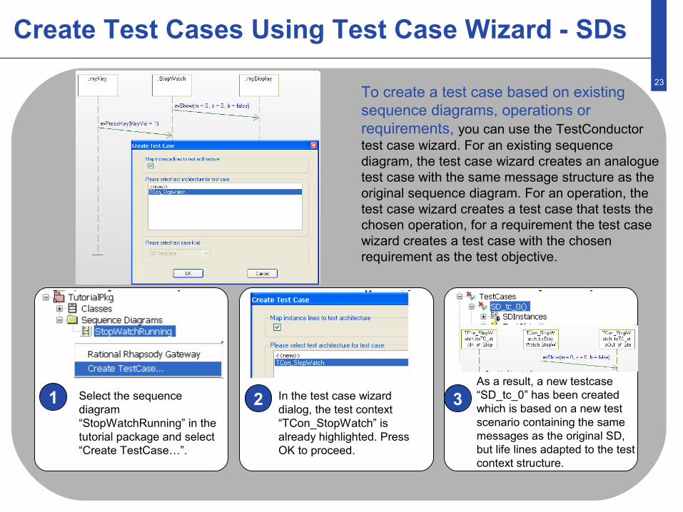
1 2 3Select the sequence diagram “StopWatchRunning” in the tutorial package and select “Create TestCase…”.
In the test case wizard dialog, the test context “TCon_StopWatch” is already highlighted. Press OK to proceed.
As a result, a new testcase “SD_tc_0” has been created which is based on a new test scenario containing the same messages as the original SD, but life lines adapted to the test context structure.
To create a test case based on existing sequence diagrams, operations or requirements, you can use the TestConductor test case wizard. For an existing sequence diagram, the test case wizard creates an analogue test case with the same message structure as the original sequence diagram. For an operation, the test case wizard creates a test case that tests the chosen operation, for a requirement the test case wizard creates a test case with the chosen requirement as the test objective.
24
Create Test Cases Using Test Case Wizard - Operations
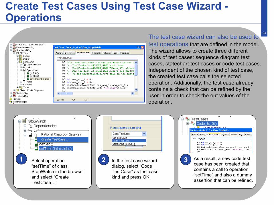
1 2 3Select operation “setTime” of class StopWatch in the browser and select “Create TestCase…”
In the test case wizard dialog, select “Code TestCase” as test case kind and press OK.
As a result, a new code test case has been created that contains a call to operation “setTime” and also a dummy assertion that can be refined.
The test case wizard can also be used to test operations that are defined in the model. The wizard allows to create three different kinds of test cases: sequence diagram test cases, statechart test cases or code test cases. Independent of the chosen kind of test case, the created test case calls the selected operation. Additionally, the test case already contains a check that can be refined by the user in order to check the out values of the operation.
25
Debugging Test Cases
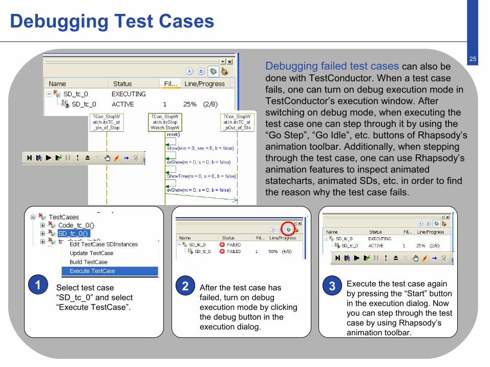
1 2 3Select test case “SD_tc_0” and select “Execute TestCase”.
After the test case has failed, turn on debug execution mode by clicking the debug button in the execution dialog.
Execute the test case again by pressing the “Start” button in the execution dialog. Now you can step through the test case by using Rhapsody’s animation toolbar.
Debugging failed test cases can also be done with TestConductor. When a test case fails, one can turn on debug execution mode in TestConductor’s execution window. After switching on debug mode, when executing the test case one can step through it by using the “Go Step”, “Go Idle”, etc. buttons of Rhapsody’s animation toolbar. Additionally, when stepping through the test case, one can use Rhapsody’s animation features to inspect animated statecharts, animated SDs, etc. in order to find the reason why the test case fails.
26
Executing Multiple Test Cases
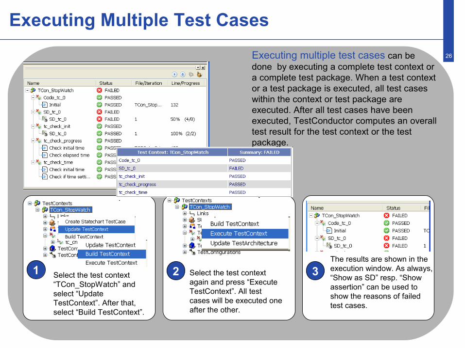
1 2 3Select the test context “TCon_StopWatch” and select “Update TestContext”. After that, select “Build TestContext”.
Select the test context again and press “Execute TestContext”. All test cases will be executed one after the other.
The results are shown in the execution window. As always, “Show as SD” resp. “Show assertion” can be used to show the reasons of failed test cases.
Executing multiple test cases can be done by executing a complete test context or a complete test package. When a test context or a test package is executed, all test cases within the context or test package are executed. After all test cases have been executed, TestConductor computes an overall test result for the test context or the test package.
27
Assessing Test Case Requirement Coverage I
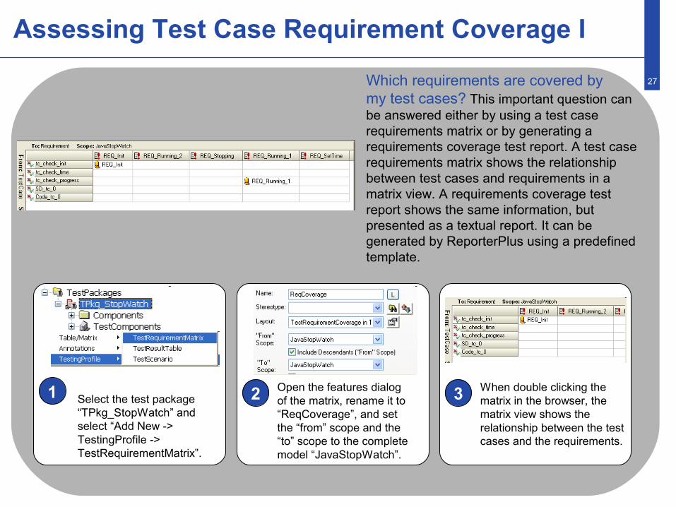
1 2 3Select the test package “TPkg_StopWatch” and select “Add New -> TestingProfile -> TestRequirementMatrix”.
Open the features dialog of the matrix, rename it to “ReqCoverage”, and set the “from” scope and the “to” scope to the complete model “JavaStopWatch”.
When double clicking the matrix in the browser, the matrix view shows the relationship between the test cases and the requirements.
Which requirements are covered by my test cases? This important question can be answered either by using a test case requirements matrix or by generating a requirements coverage test report. A test case requirements matrix shows the relationship between test cases and requirements in a matrix view. A requirements coverage test report shows the same information, but presented as a textual report. It can be generated by ReporterPlus using a predefined template.
28
Assessing Test Case Requirement Coverage II
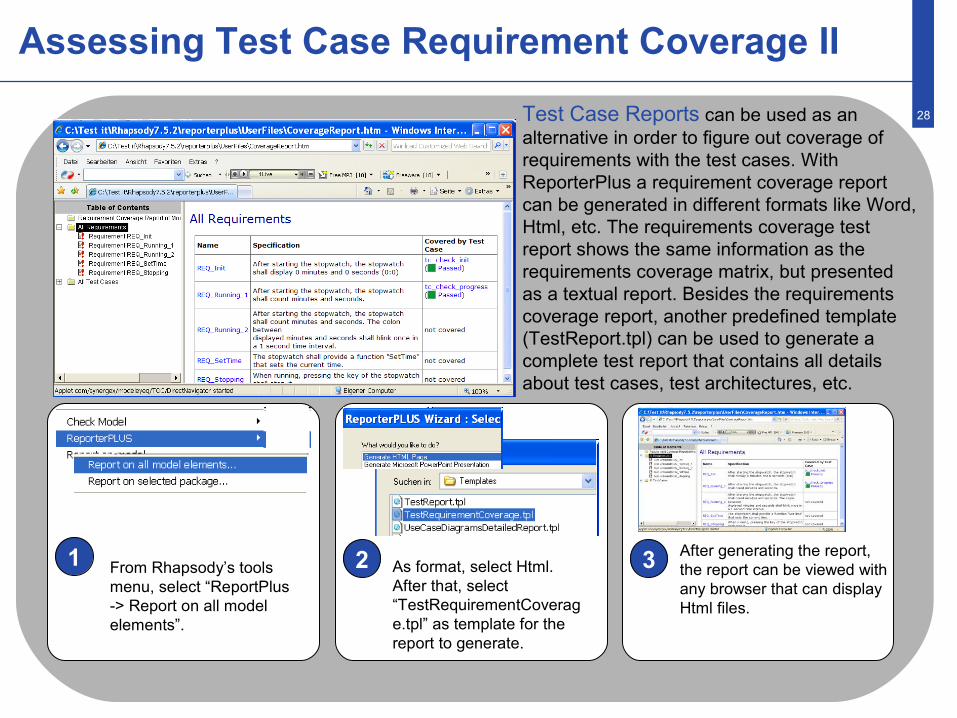
1 2 3From Rhapsody’s tools menu, select “ReportPlus-> Report on all model elements”.
As format, select Html. After that, select “TestRequirementCoverage.tpl” as template for the report to generate.
After generating the report, the report can be viewed with any browser that can display Html files.
Test Case Reports can be used as an alternative in order to figure out coverage of requirements with the test cases. With ReporterPlus a requirement coverage report can be generated in different formats like Word, Html, etc. The requirements coverage test report shows the same information as the requirements coverage matrix, but presented as a textual report. Besides the requirements coverage report, another predefined template (TestReport.tpl) can be used to generate a complete test report that contains all details about test cases, test architectures, etc.
29
Assessing Test Case Model Coverage
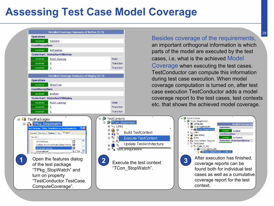
1 2 3Open the features dialog of the test package “TPkg_StopWatch” and turn on property “TestConductor.TestCase.ComputeCoverage”.
Execute the test context “TCon_StopWatch”.
After execution has finished, coverage reports can be found both for individual test cases as well as a cumulative coverage report for the test context.
Besides coverage of the requirements, an important orthogonal information is which parts of the model are executed by the test cases, i.e, what is the achieved Model Coverage when executing the test cases. TestConductor can compute this information during test case execution. When model coverage computation is turned on, after test case execution TestConductor adds a model coverage report to the test cases, test contexts etc. that shows the achieved model coverage.
Conclusion
The high-grade automation in the Rhapsody Testing Environment with TestConductor
generates complete, immediately executable test architectures in shortest time with a few mouse clicks.
makes it for the first time possible to implement cyclically quality assurance measures in early phases of the development.
increases substantially the planning reliability for projects, because design errors and subsequent errors will be recognized very early.
makes statements about the coverage rates for both the model elements and model code. Developers can easily and fast analyze reasons for not coved elements.
highly automates the testing process and can save test development time compared to traditional approaches.
31
More Information …
For further information, especially technical news, visit our internet information portal or contact one of our worldwide sale agencies.
IBM® Rational® Software Support provides you with technical assistance. The IBM Rational Software Support Home page for Rational products can be found at http://www.ibm.com/software/rational/support/.
For contact information and guidelines or reference materials that you need for support, read the IBM Software Support Handbook.
For Rational software product news, events, and other information, visit the IBM Rational Software Web site.
Voice support is available to all current contract holders by dialing a telephone number in your country (where available). For specific country phone numbers, go to http://www.ibm.com/planetwide.
Before you contact IBM Rational Software Support, gather the background information that you will need to describe your problem. When describing a problem to an IBM software support specialist, be as specific as possible and include all relevant background information so that the specialist can help you solve the problem efficiently. To save time, know the answers to these questions:
• What software versions were you running when the problem occurred? • Do you have logs, traces, or messages that are related to the problem? • Can you reproduce the problem? If so, what steps do you take to reproduce it? • Is there a workaround for the problem? If so, be prepared to describe the workaround.