Embed Size (px)
Citation preview
Tutorials:UsingAutoCAD Files®
Design 2010
Autodesk® 3ds® Max Design 2010 Software© 2009 Autodesk, Inc. All rights reserved. Except as otherwise permitted by Autodesk, Inc., this publication, or parts thereof, may not bereproduced in any form, by any method, for any purpose.Certain materials included in this publication are reprinted with the permission of the copyright holder.The following are registered trademarks or trademarks of Autodesk, Inc., in the USA and other countries: 3DEC (design/logo), 3December,3December.com, 3ds Max, ADI, Alias, Alias (swirl design/logo), AliasStudio, Alias|Wavefront (design/logo), ATC, AUGI, AutoCAD, AutoCADLearning Assistance, AutoCAD LT, AutoCAD Simulator, AutoCAD SQL Extension, AutoCAD SQL Interface, Autodesk, Autodesk Envision, AutodeskInsight, Autodesk Intent, Autodesk Inventor, Autodesk Map, Autodesk MapGuide, Autodesk Streamline, AutoLISP, AutoSnap, AutoSketch,AutoTrack, Backdraft, Built with ObjectARX (logo), Burn, Buzzsaw, CAiCE, Can You Imagine, Character Studio, Cinestream, Civil 3D, Cleaner,Cleaner Central, ClearScale, Colour Warper, Combustion, Communication Specification, Constructware, Content Explorer, Create>what's>Next>(design/logo), Dancing Baby (image), DesignCenter, Design Doctor, Designer's Toolkit, DesignKids, DesignProf, DesignServer, DesignStudio,Design|Studio (design/logo), Design Web Format, Discreet, DWF, DWG, DWG (logo), DWG Extreme, DWG TrueConvert, DWG TrueView, DXF,Ecotect, Exposure, Extending the Design Team, Face Robot, FBX, Filmbox, Fire, Flame, Flint, FMDesktop, Freewheel, Frost, GDX Driver, Gmax,Green Building Studio, Heads-up Design, Heidi, HumanIK, IDEA Server, i-drop, ImageModeler, iMOUT, Incinerator, Inferno, Inventor, InventorLT, Kaydara, Kaydara (design/logo), Kynapse, Kynogon, LandXplorer, LocationLogic, Lustre, Matchmover, Maya, Mechanical Desktop, Moonbox,MotionBuilder, Movimento, Mudbox, NavisWorks, ObjectARX, ObjectDBX, Open Reality, Opticore, Opticore Opus, PolarSnap, PortfolioWall,Powered with Autodesk Technology, Productstream, ProjectPoint, ProMaterials, RasterDWG, Reactor, RealDWG, Real-time Roto, REALVIZ,Recognize, Render Queue, Retimer,Reveal, Revit, Showcase, ShowMotion, SketchBook, Smoke, Softimage, Softimage|XSI (design/logo),SteeringWheels, Stitcher, Stone, StudioTools, Topobase, Toxik, TrustedDWG, ViewCube, Visual, Visual Construction, Visual Drainage, VisualLandscape, Visual Survey, Visual Toolbox, Visual LISP, Voice Reality, Volo, Vtour, Wire, Wiretap, WiretapCentral, XSI, and XSI (design/logo).
TrademarksThe following are registered trademarks or trademarks of Autodesk Canada Co. in the USA and/or Canada and other countries: Backburner,Multi-Master Editing, River, and Sparks.The following are registered trademarks or trademarks of Moldflow Corp. in the USA and/or other countries: Moldflow MPA, MPA (design/logo),Moldflow Plastics Advisers, MPI, MPI (design/logo), Moldflow Plastics Insight, MPX, MPX (design/logo), Moldflow Plastics Xpert.clothfx™ is a trademark of Size8 Software, Inc. Havok.com™ is a trademark or registered trademark of Havok.com Inc. or its licensors. Intel is aregistered trademark of Intel Corporation. mental ray is a registered trademark of mental images GmbH licensed for use by Autodesk, Inc. Allother brand names, product names or trademarks belong to their respective holders.
DisclaimerTHIS PUBLICATION AND THE INFORMATION CONTAINED HEREIN IS MADE AVAILABLE BY AUTODESK, INC. "AS IS." AUTODESK, INC. DISCLAIMSALL WARRANTIES, EITHER EXPRESS OR IMPLIED, INCLUDING BUT NOT LIMITED TO ANY IMPLIED WARRANTIES OF MERCHANTABILITY ORFITNESS FOR A PARTICULAR PURPOSE REGARDING THESE MATERIALS.
Using AutoCAD Files
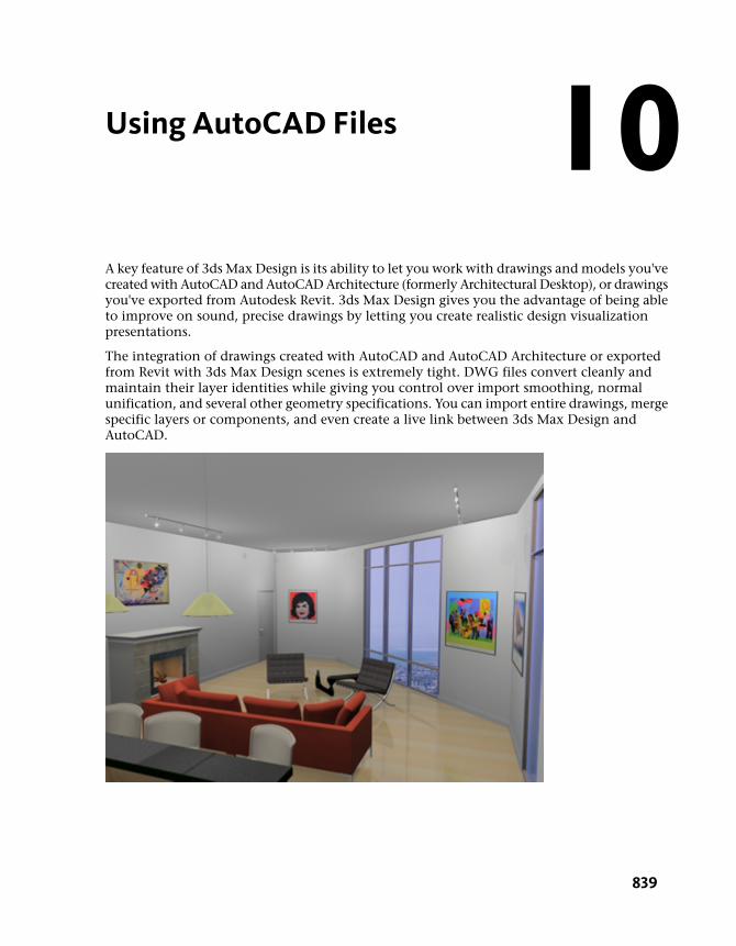
A key feature of 3ds Max Design is its ability to let you work with drawings and models you'vecreated with AutoCAD and AutoCAD Architecture (formerly Architectural Desktop), or drawingsyou've exported from Autodesk Revit. 3ds Max Design gives you the advantage of being ableto improve on sound, precise drawings by letting you create realistic design visualizationpresentations.
The integration of drawings created with AutoCAD and AutoCAD Architecture or exportedfrom Revit with 3ds Max Design scenes is extremely tight. DWG files convert cleanly andmaintain their layer identities while giving you control over import smoothing, normalunification, and several other geometry specifications. You can import entire drawings, mergespecific layers or components, and even create a live link between 3ds Max Design andAutoCAD.
10
839
In this tutorial, you will learn how to:
■ Prepare an AutoCAD drawing for import
■ Use an AutoCAD drawing as the basis for a photorealistic walkthrough animation
■ Use the File Link Manager to create a live link between AutoCAD and 3ds Max Design
Skill Level: Beginner
Time to Complete: 1.5 to 2 hours
Creating a Walkthrough from an AutoCADDrawing
This tutorial is a guide to creating a virtual visit of a room in a house usingAutoCAD and 3ds Max Design. In it, you will learn production techniquesused for creating a photorealistic animation sequence from a 2D house plan.
840 | Chapter 10 Using AutoCAD Files
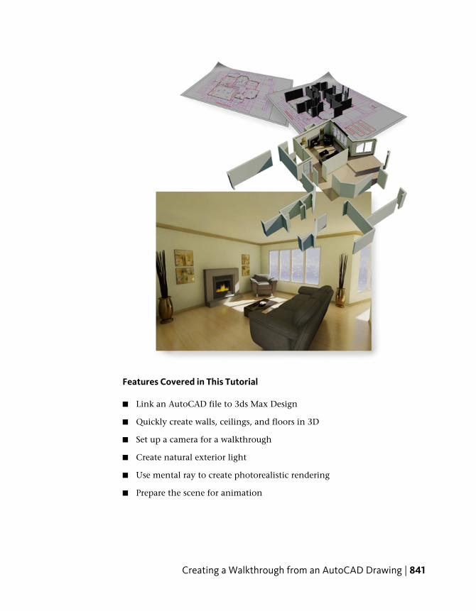
Features Covered in This Tutorial
■ Link an AutoCAD file to 3ds Max Design
■ Quickly create walls, ceilings, and floors in 3D
■ Set up a camera for a walkthrough
■ Create natural exterior light
■ Use mental ray to create photorealistic rendering
■ Prepare the scene for animation
Creating a Walkthrough from an AutoCAD Drawing | 841
Preparing and Exporting the DWG File
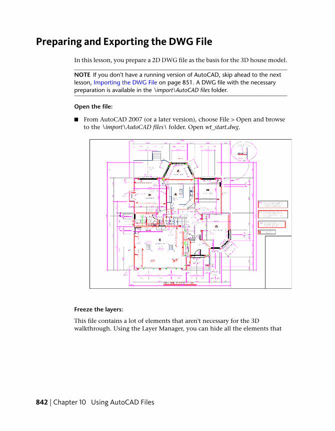
In this lesson, you prepare a 2D DWG file as the basis for the 3D house model.
NOTE If you don't have a running version of AutoCAD, skip ahead to the nextlesson, Importing the DWG File on page 851. A DWG file with the necessarypreparation is available in the \import\AutoCAD files folder.
Open the file:
■ From AutoCAD 2007 (or a later version), choose File > Open and browseto the \import\AutoCAD files\ folder. Open wt_start.dwg.
Freeze the layers:
This file contains a lot of elements that aren't necessary for the 3Dwalkthrough. Using the Layer Manager, you can hide all the elements that
842 | Chapter 10 Using AutoCAD Files
you will not use. The only layers that are required for this tutorial are 01-Wallsand 02-Windows.
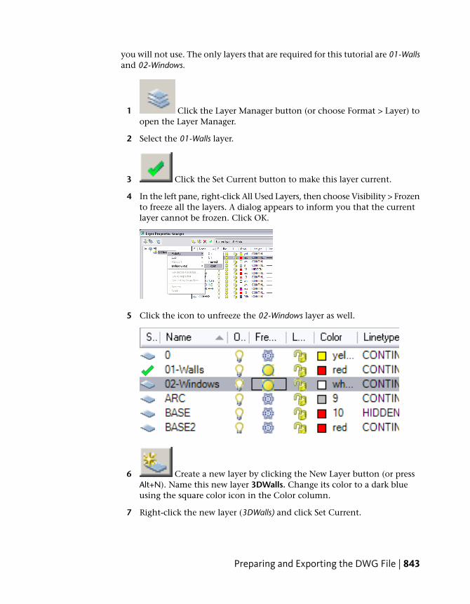
1 Click the Layer Manager button (or choose Format > Layer) toopen the Layer Manager.
2 Select the 01-Walls layer.
3 Click the Set Current button to make this layer current.
4 In the left pane, right-click All Used Layers, then choose Visibility > Frozento freeze all the layers. A dialog appears to inform you that the currentlayer cannot be frozen. Click OK.
5 Click the icon to unfreeze the 02-Windows layer as well.
6 Create a new layer by clicking the New Layer button (or pressAlt+N). Name this new layer 3DWalls. Change its color to a dark blueusing the square color icon in the Color column.
7 Right-click the new layer (3DWalls) and click Set Current.
Preparing and Exporting the DWG File | 843
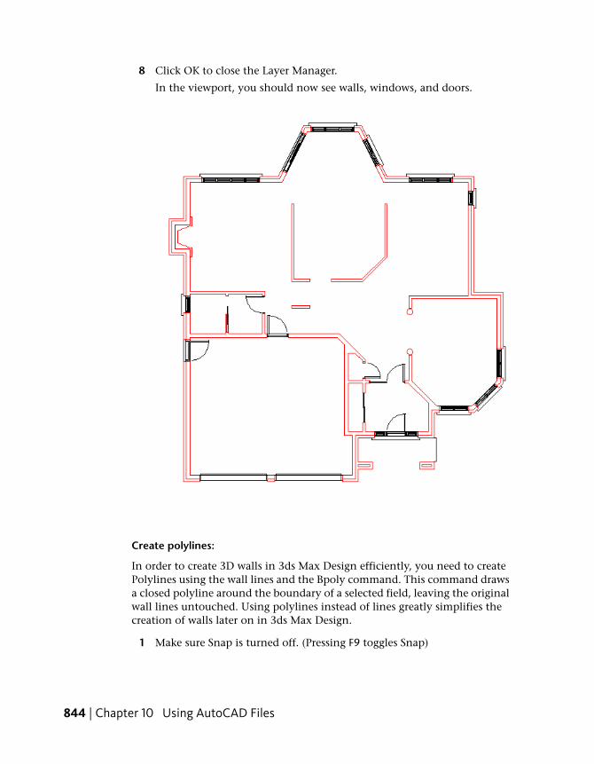
8 Click OK to close the Layer Manager.
In the viewport, you should now see walls, windows, and doors.
Create polylines:
In order to create 3D walls in 3ds Max Design efficiently, you need to createPolylines using the wall lines and the Bpoly command. This command drawsa closed polyline around the boundary of a selected field, leaving the originalwall lines untouched. Using polylines instead of lines greatly simplifies thecreation of walls later on in 3ds Max Design.
1 Make sure Snap is turned off. (Pressing F9 toggles Snap)
844 | Chapter 10 Using AutoCAD Files
2 In the viewport, zoom out until you see all the wall lines. This is requiredfor the Bpoly command to work.
3 Type bpoly and then press Enter.
A Boundary Creation dialog appears.
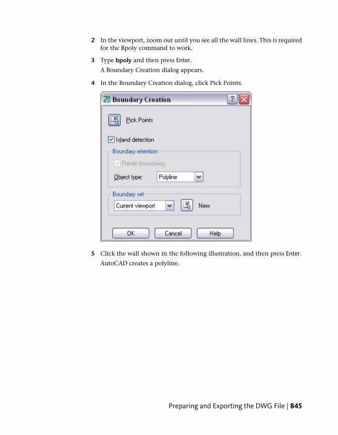
4 In the Boundary Creation dialog, click Pick Points.
5 Click the wall shown in the following illustration, and then press Enter.
AutoCAD creates a polyline.
Preparing and Exporting the DWG File | 845
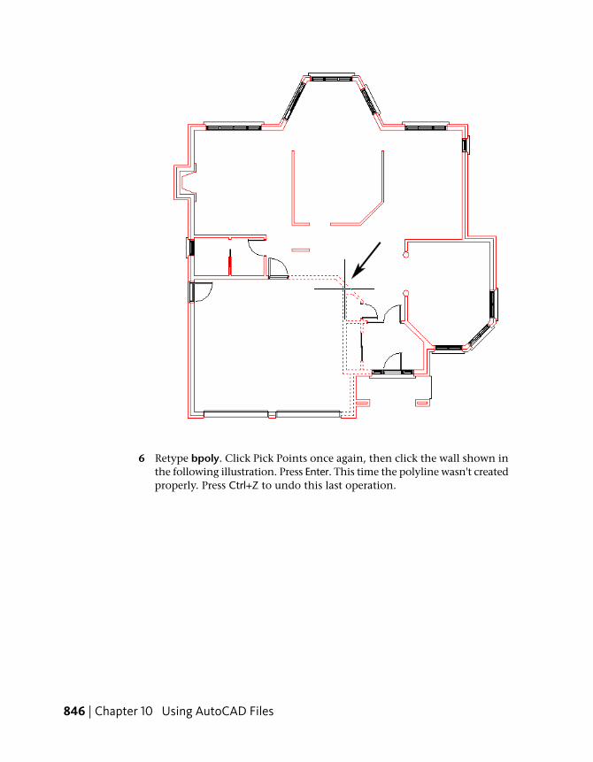
6 Retype bpoly. Click Pick Points once again, then click the wall shown inthe following illustration. Press Enter. This time the polyline wasn't createdproperly. Press Ctrl+Z to undo this last operation.
846 | Chapter 10 Using AutoCAD Files
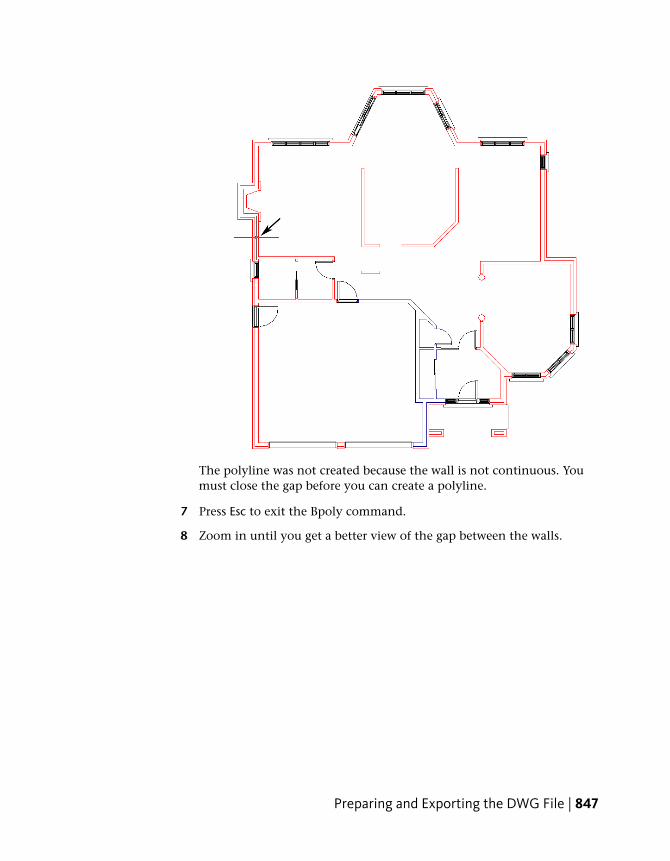
The polyline was not created because the wall is not continuous. Youmust close the gap before you can create a polyline.
7 Press Esc to exit the Bpoly command.
8 Zoom in until you get a better view of the gap between the walls.
Preparing and Exporting the DWG File | 847
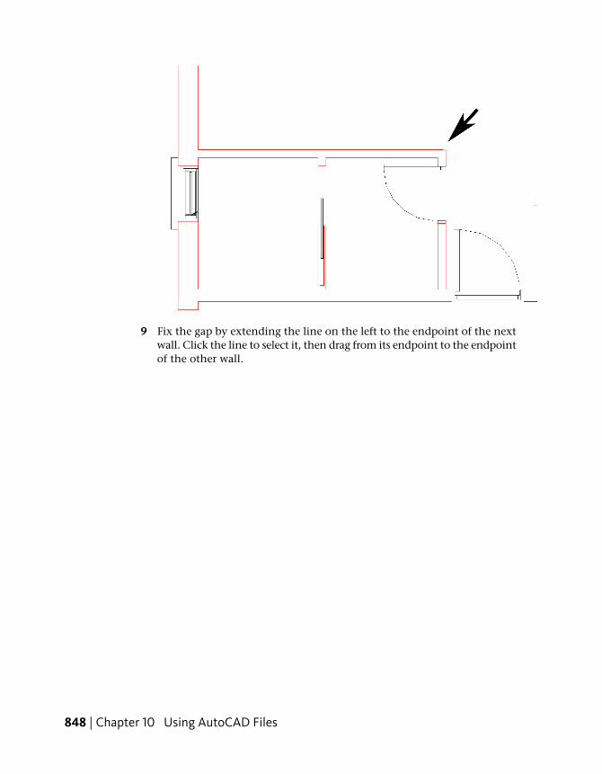
9 Fix the gap by extending the line on the left to the endpoint of the nextwall. Click the line to select it, then drag from its endpoint to the endpointof the other wall.
848 | Chapter 10 Using AutoCAD Files
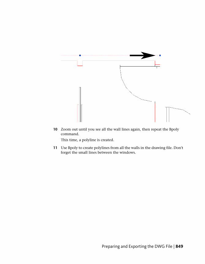
10 Zoom out until you see all the wall lines again, then repeat the Bpolycommand.
This time, a polyline is created.
11 Use Bpoly to create polylines from all the walls in the drawing file. Don'tforget the small lines between the windows.
Preparing and Exporting the DWG File | 849
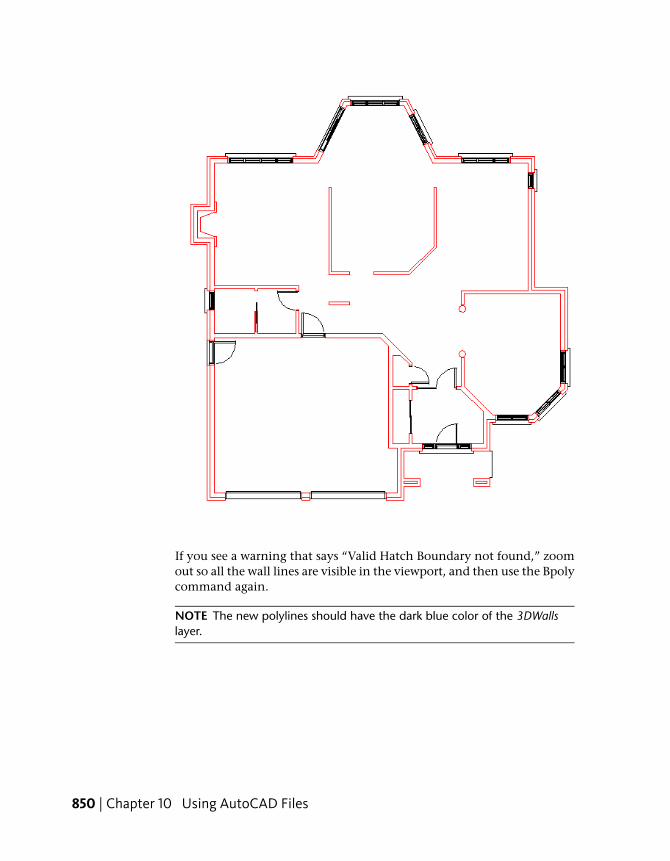
If you see a warning that says “Valid Hatch Boundary not found,” zoomout so all the wall lines are visible in the viewport, and then use the Bpolycommand again.
NOTE The new polylines should have the dark blue color of the 3DWallslayer.
850 | Chapter 10 Using AutoCAD Files
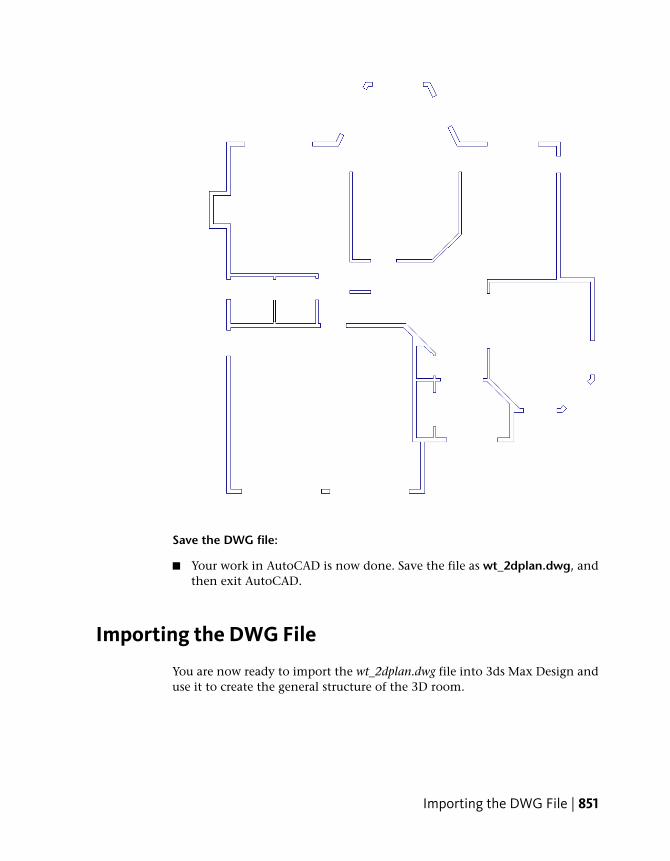
Save the DWG file:
■ Your work in AutoCAD is now done. Save the file as wt_2dplan.dwg, andthen exit AutoCAD.
Importing the DWG File
You are now ready to import the wt_2dplan.dwg file into 3ds Max Design anduse it to create the general structure of the 3D room.
Importing the DWG File | 851
Set up the units:
The AutoCAD file you are importing is measured in feet and inches. It is bestto use the same units setting in 3ds Max Design.
1 From the Customize menu, choose Units Setup.
2 In the Units Setup dialog, choose US Standard > Feet With FractionalInches. Leave the other values set to their defaults, and then click OK.
Import the DWG file:
1 From the Application menu, choose Import.
A Select File To Import dialog appears.
2 Browse to \import\autocad files and choose the file wt_2dplan.dwg, or usethe one you created yourself in the first lesson.
After a pause, an AutoCAD DWG/DXF Import Options dialog appears.
Adjust the import options:
1 On the Geometry tab of the AutoCAD DWG/DXF Import Options dialog,leave the settings at their defaults. (These are shown in the followingillustration.) Before you click OK, you must change settings on the Layerstab.
852 | Chapter 10 Using AutoCAD Files
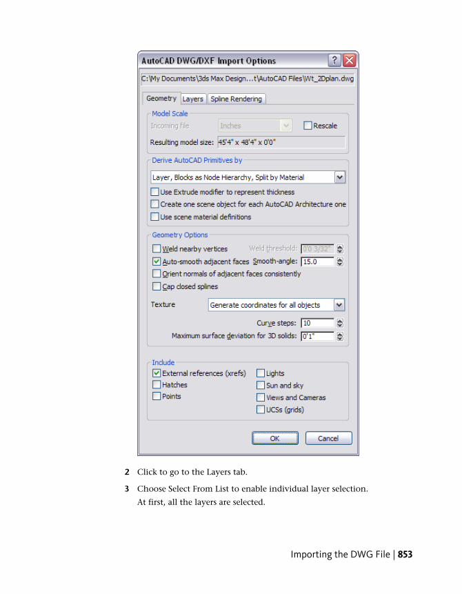
2 Click to go to the Layers tab.
3 Choose Select From List to enable individual layer selection.
At first, all the layers are selected.
Importing the DWG File | 853
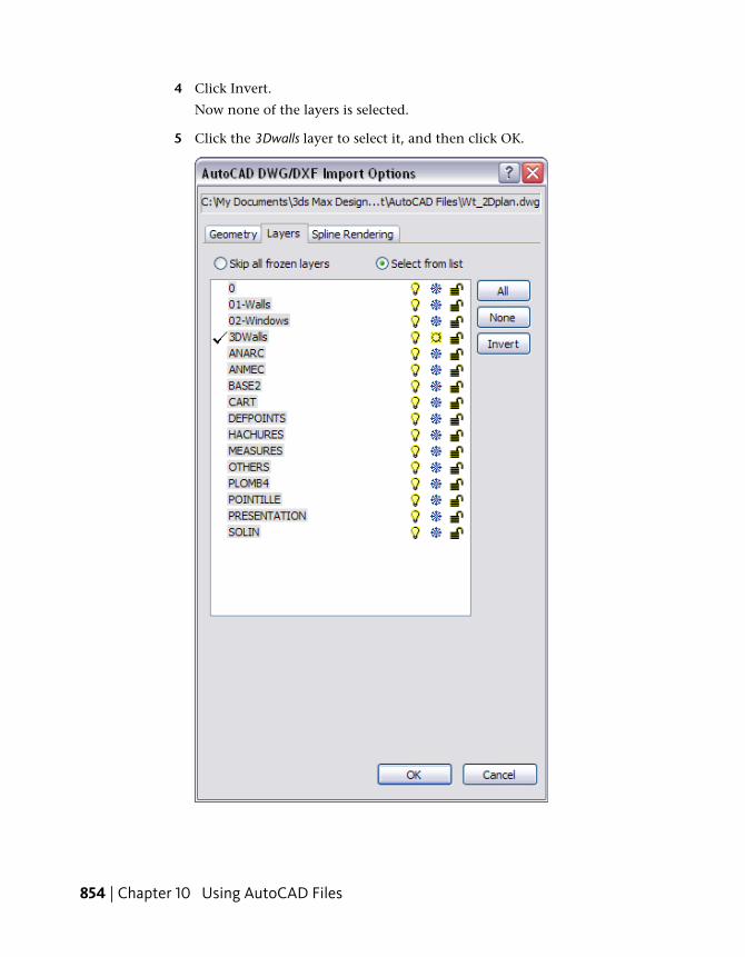
4 Click Invert.
Now none of the layers is selected.
5 Click the 3Dwalls layer to select it, and then click OK.
854 | Chapter 10 Using AutoCAD Files
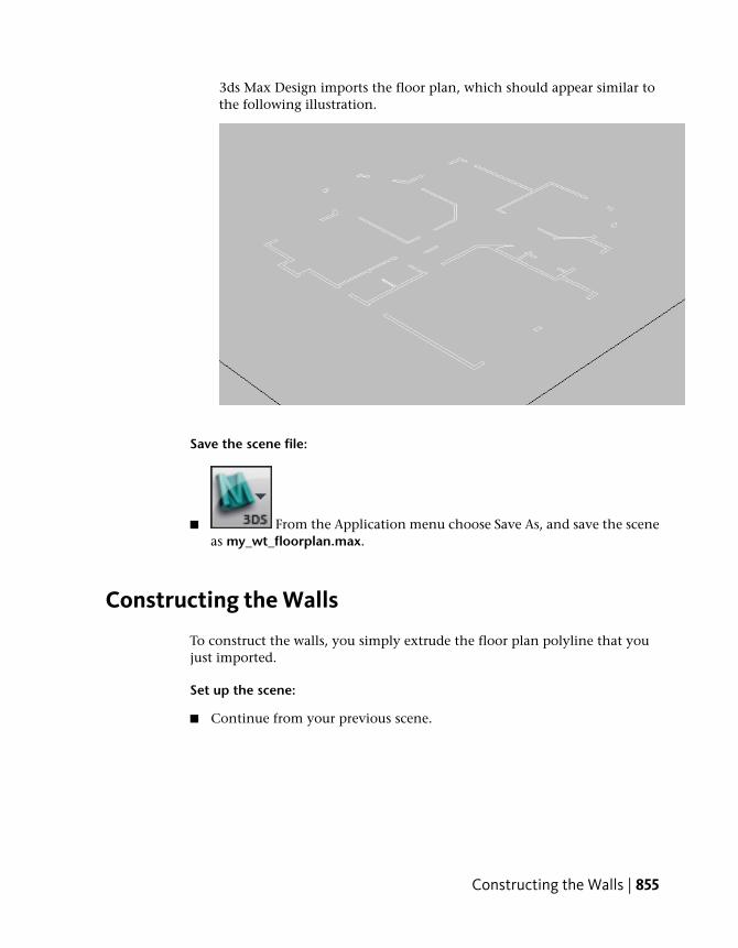
3ds Max Design imports the floor plan, which should appear similar tothe following illustration.
Save the scene file:
■ From the Application menu choose Save As, and save the sceneas my_wt_floorplan.max.
Constructing the Walls
To construct the walls, you simply extrude the floor plan polyline that youjust imported.
Set up the scene:
■ Continue from your previous scene.
Constructing the Walls | 855
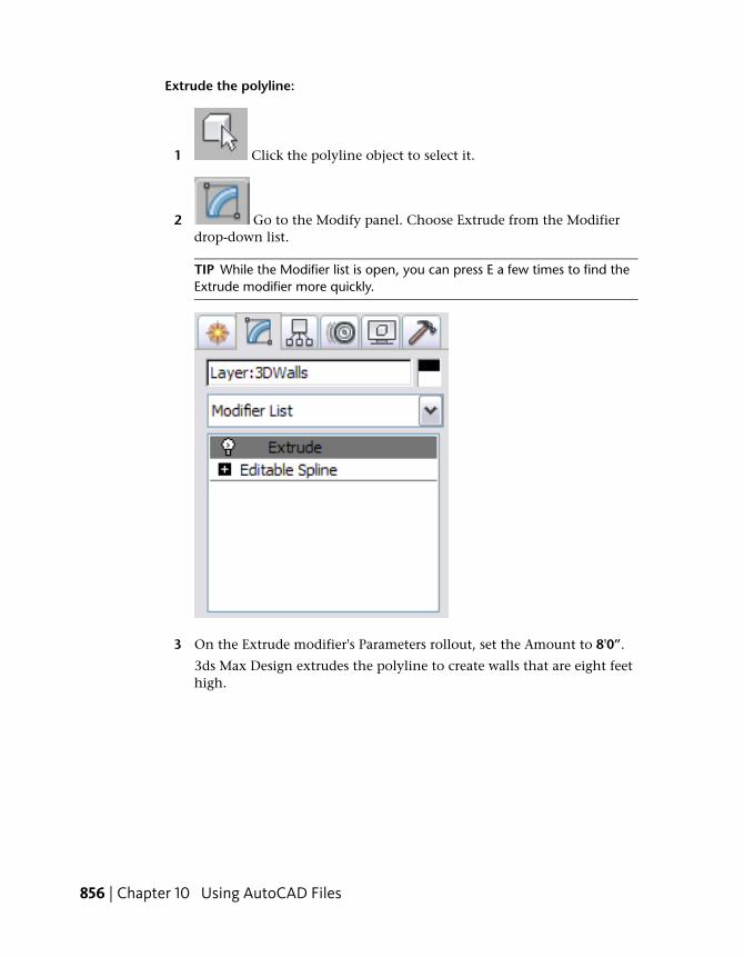
Extrude the polyline:
1 Click the polyline object to select it.
2 Go to the Modify panel. Choose Extrude from the Modifierdrop-down list.
TIP While the Modifier list is open, you can press E a few times to find theExtrude modifier more quickly.
3 On the Extrude modifier's Parameters rollout, set the Amount to 8'0”.
3ds Max Design extrudes the polyline to create walls that are eight feethigh.
856 | Chapter 10 Using AutoCAD Files
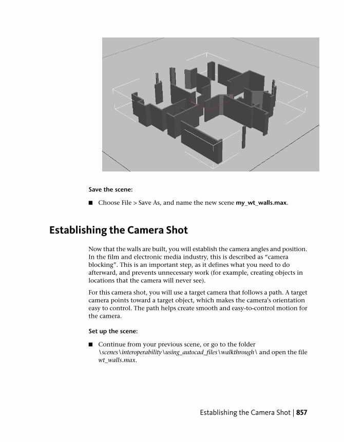
Save the scene:
■ Choose File > Save As, and name the new scene my_wt_walls.max.
Establishing the Camera Shot
Now that the walls are built, you will establish the camera angles and position.In the film and electronic media industry, this is described as “camerablocking”. This is an important step, as it defines what you need to doafterward, and prevents unnecessary work (for example, creating objects inlocations that the camera will never see).
For this camera shot, you will use a target camera that follows a path. A targetcamera points toward a target object, which makes the camera's orientationeasy to control. The path helps create smooth and easy-to-control motion forthe camera.
Set up the scene:
■ Continue from your previous scene, or go to the folder\scenes\interoperability\using_autocad_files\walkthrough\ and open the filewt_walls.max.
Establishing the Camera Shot | 857
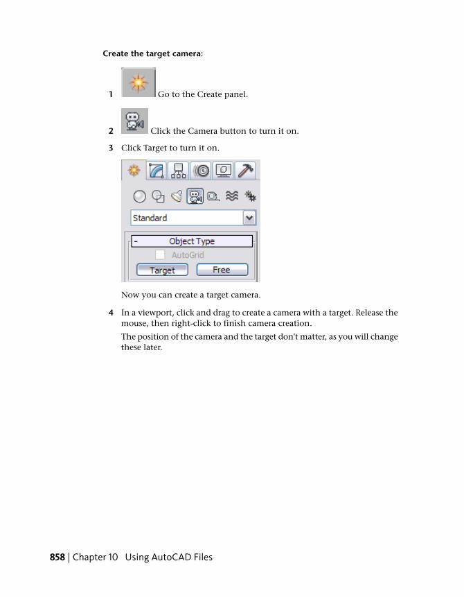
Create the target camera:
1 Go to the Create panel.
2 Click the Camera button to turn it on.
3 Click Target to turn it on.
Now you can create a target camera.
4 In a viewport, click and drag to create a camera with a target. Release themouse, then right-click to finish camera creation.
The position of the camera and the target don't matter, as you will changethese later.
858 | Chapter 10 Using AutoCAD Files
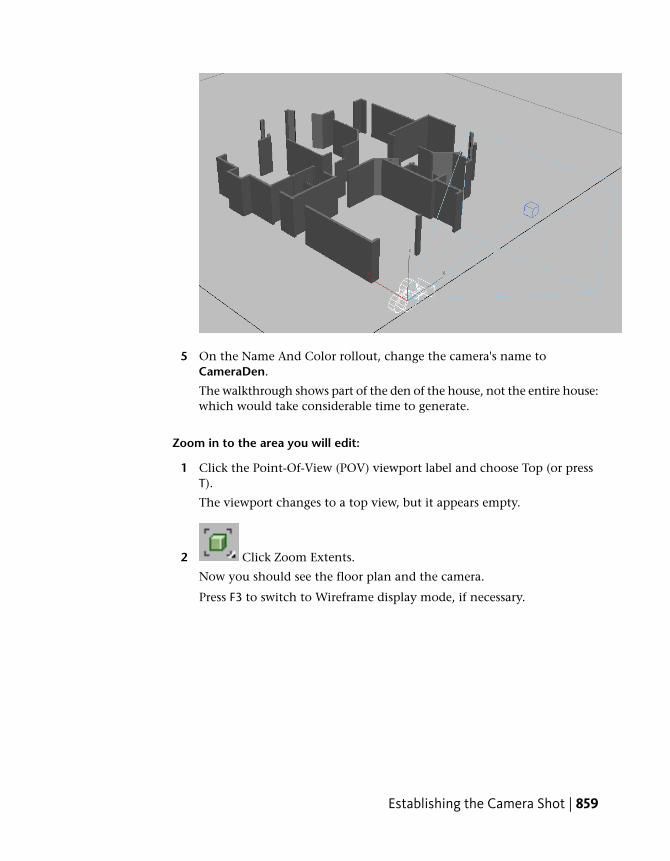
5 On the Name And Color rollout, change the camera's name toCameraDen.
The walkthrough shows part of the den of the house, not the entire house:which would take considerable time to generate.
Zoom in to the area you will edit:
1 Click the Point-Of-View (POV) viewport label and choose Top (or pressT).
The viewport changes to a top view, but it appears empty.
2 Click Zoom Extents.
Now you should see the floor plan and the camera.
Press F3 to switch to Wireframe display mode, if necessary.
Establishing the Camera Shot | 859
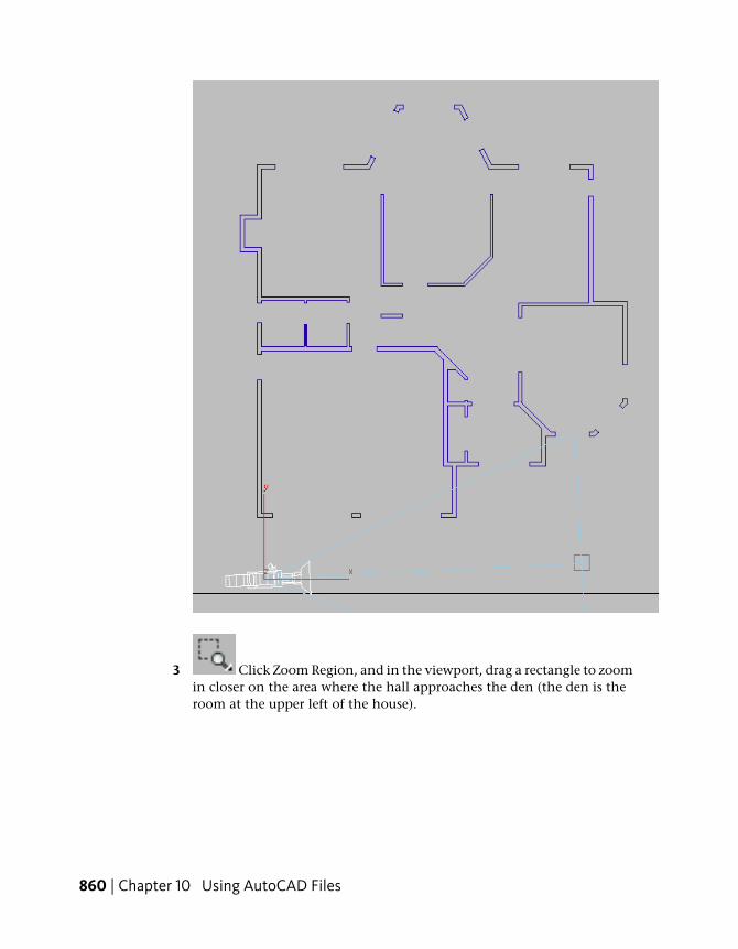
3 Click Zoom Region, and in the viewport, drag a rectangle to zoomin closer on the area where the hall approaches the den (the den is theroom at the upper left of the house).
860 | Chapter 10 Using AutoCAD Files
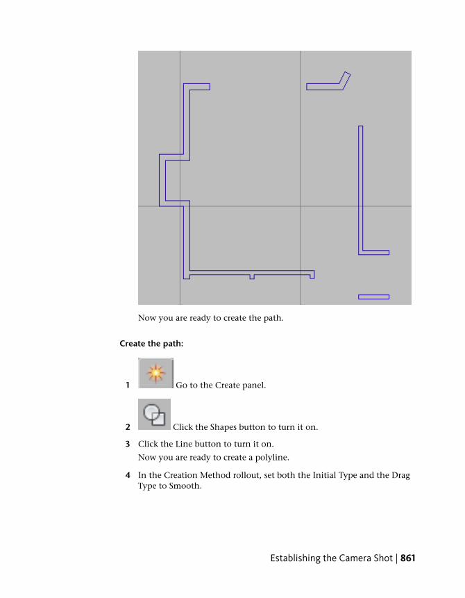
Now you are ready to create the path.
Create the path:
1 Go to the Create panel.
2 Click the Shapes button to turn it on.
3 Click the Line button to turn it on.
Now you are ready to create a polyline.
4 In the Creation Method rollout, set both the Initial Type and the DragType to Smooth.
Establishing the Camera Shot | 861
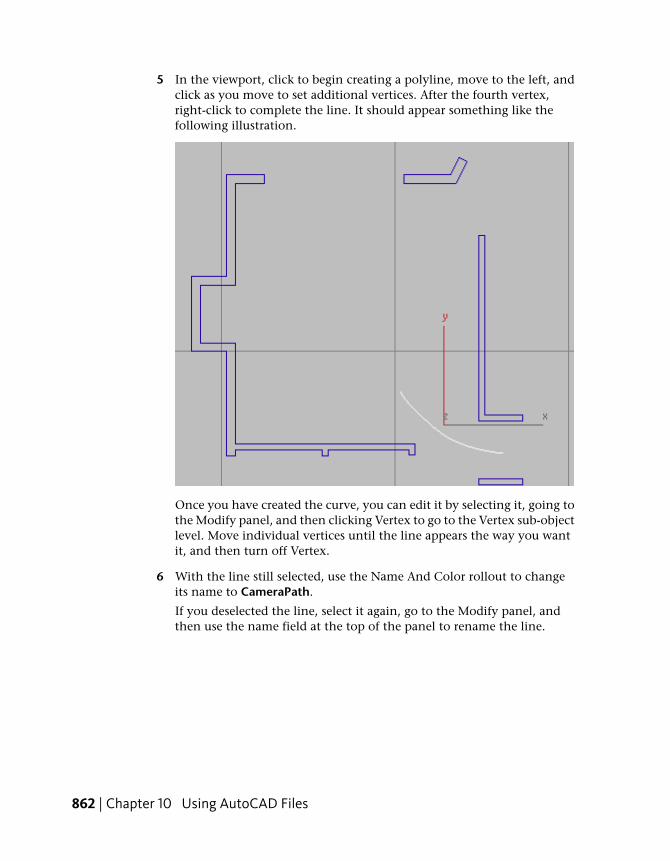
5 In the viewport, click to begin creating a polyline, move to the left, andclick as you move to set additional vertices. After the fourth vertex,right-click to complete the line. It should appear something like thefollowing illustration.
Once you have created the curve, you can edit it by selecting it, going tothe Modify panel, and then clicking Vertex to go to the Vertex sub-objectlevel. Move individual vertices until the line appears the way you wantit, and then turn off Vertex.
6 With the line still selected, use the Name And Color rollout to changeits name to CameraPath.
If you deselected the line, select it again, go to the Modify panel, andthen use the name field at the top of the panel to rename the line.
862 | Chapter 10 Using AutoCAD Files
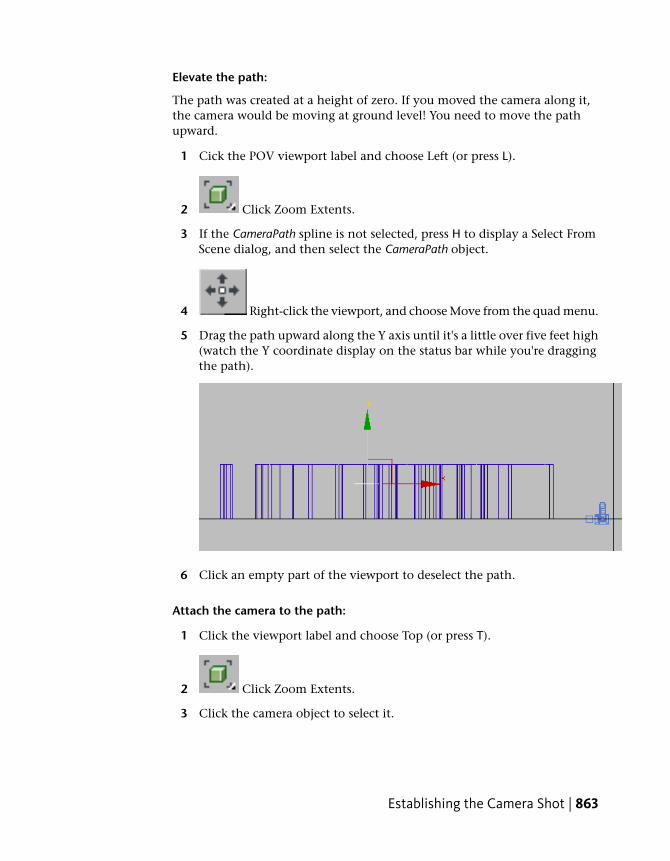
Elevate the path:
The path was created at a height of zero. If you moved the camera along it,the camera would be moving at ground level! You need to move the pathupward.
1 Cick the POV viewport label and choose Left (or press L).
2 Click Zoom Extents.
3 If the CameraPath spline is not selected, press H to display a Select FromScene dialog, and then select the CameraPath object.
4 Right-click the viewport, and choose Move from the quad menu.
5 Drag the path upward along the Y axis until it's a little over five feet high(watch the Y coordinate display on the status bar while you're draggingthe path).
6 Click an empty part of the viewport to deselect the path.
Attach the camera to the path:
1 Click the viewport label and choose Top (or press T).
2 Click Zoom Extents.
3 Click the camera object to select it.
Establishing the Camera Shot | 863
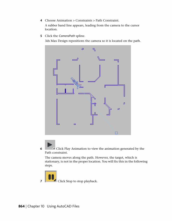
4 Choose Animation > Constraints > Path Constraint.
A rubber band line appears, leading from the camera to the cursorlocation.
5 Click the CameraPath spline.
3ds Max Design repositions the camera so it is located on the path.
6 Click Play Animation to view the animation generated by thePath constraint.
The camera moves along the path. However, the target, which isstationary, is not in the proper location. You will fix this in the followingsteps.
7 Click Stop to stop playback.
864 | Chapter 10 Using AutoCAD Files
Orient the camera:
1 In viewports, the camera's target is represented as a small cube. Click thiscube to select it, and then move it to a position inside the den.
As you move the target, the camera rotates to remain aimed in the target'sdirection.
2 Click the viewport label and choose Left (or press L).
3 If the walls and camera aren't visible, click Zoom Extents.
The target is still at ground level (Y=0), so the camera is aimed at thefloor.
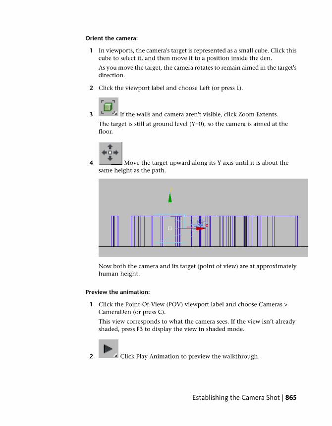
4 Move the target upward along its Y axis until it is about thesame height as the path.
Now both the camera and its target (point of view) are at approximatelyhuman height.
Preview the animation:
1 Click the Point-Of-View (POV) viewport label and choose Cameras >CameraDen (or press C).
This view corresponds to what the camera sees. If the view isn’t alreadyshaded, press F3 to display the view in shaded mode.
2 Click Play Animation to preview the walkthrough.
Establishing the Camera Shot | 865
As the animation plays, the camera moves into the room.
3 Click Stop to stop playback.
Set the camera's field of view:
The room is fairly small. Decreasing the camera's focal length and increasingits field of view (FOV) lets the camera show more of the room.
1 Press H to display a Select Objects dialog, then choose the CameraDenobject.
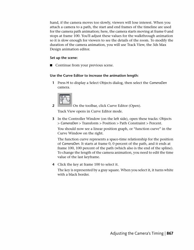
2 Go to the Modify panel. On the Parameters rollout, set the Lens value to18.0 mm and the FOV value to 90 degrees.
Now the camera viewport shows more of the house.
TIP FOV values greater than 90 degrees tend to give a distorted view ofobjects.
Save your work:
■ Choose File > Save As, and save the file as my_wt_camera.max.If you want to do additional editing of the camera position, move the pathto which it is attached, or the vertices of that path. You can't move thecamera itself, because it is constrained to this path. You can move thecamera’s target, if you want to.
Adjusting the Camera's Timing
Camera timing is important. If the camera moves too fast, viewers will missimportant elements of the animation (and might become dizzy). On the other
866 | Chapter 10 Using AutoCAD Files
hand, if the camera moves too slowly, viewers will lose interest. When youattach a camera to a path, the start and end frames of the timeline are usedfor the camera path animation; here, the camera starts moving at frame 0 andstops at frame 100. You'll adjust these values for the walkthrough animationso it is slow enough for viewers to see the details of the room. To modify theduration of the camera animation, you will use Track View, the 3ds MaxDesign animation editor.
Set up the scene:
■ Continue from your previous scene.
Use the Curve Editor to increase the animation length:
1 Press H to display a Select Objects dialog, then select the CameraDencamera.
2 On the toolbar, click Curve Editor (Open).
Track View opens in Curve Editor mode.
3 In the Controller Window (on the left side), open these tracks: Objects> CameraDen > Transform > Position > Path Constraint > Percent.
You should now see a linear position graph, or “function curve” in theCurve Window on the right.
The function curve represents a space-time relationship for the positionof CameraDen. It starts at frame 0, 0 percent of the path, and it ends atframe 100, 100 percent of the path (which also is the end of the spline).To change the length of the camera animation, you need to edit the timevalue of the last keyframe.
4 Click the key at frame 100 to select it.
The key is represented by a gray square. When you select it, it turns whitewith a black border.
Adjusting the Camera's Timing | 867
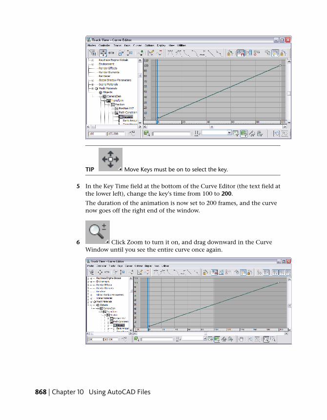
TIP Move Keys must be on to select the key.
5 In the Key Time field at the bottom of the Curve Editor (the text field atthe lower left), change the key's time from 100 to 200.
The duration of the animation is now set to 200 frames, and the curvenow goes off the right end of the window.
6 Click Zoom to turn it on, and drag downward in the CurveWindow until you see the entire curve once again.
868 | Chapter 10 Using AutoCAD Files
7 Click Zoom again to turn it off.
Use the Curve Editor to adjust the camera's speed:
Right now, the camera has a constant speed between frames 0 and 200. Thisis indicated by the linear “curve” in the curve window. The camera startssuddenly and stops suddenly, which is not typical for real-world movement.It would be more realistic, and more pleasant to viewers' eyes, if the camerabegan moving slowly, speeded up a bit, and then slowed down before comingto a stop. In animation, the expression for this type of motion is “slow in,slow out.”
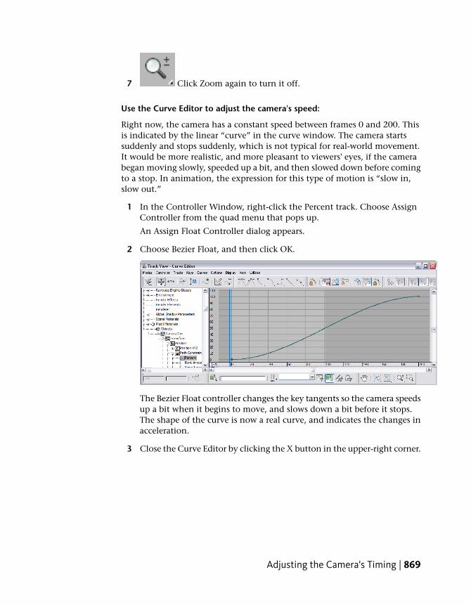
1 In the Controller Window, right-click the Percent track. Choose AssignController from the quad menu that pops up.
An Assign Float Controller dialog appears.
2 Choose Bezier Float, and then click OK.
The Bezier Float controller changes the key tangents so the camera speedsup a bit when it begins to move, and slows down a bit before it stops.The shape of the curve is now a real curve, and indicates the changes inacceleration.
3 Close the Curve Editor by clicking the X button in the upper-right corner.
Adjusting the Camera's Timing | 869
Change the time configuration:
You have changed the keys for the camera to indicate a 200-frame animation,but 3ds Max Design is still set to render only 100 frames. You also need tochange this setting.
1 Click Time Configuration in the animation controls at the lowerright of the 3ds Max Design window.
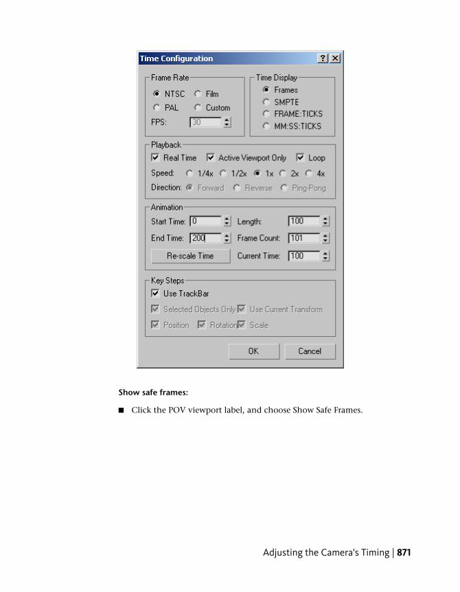
A Time Configuration dialog appears.
2 In the Animation group, change the End Time value to 200, and thenclick OK.
870 | Chapter 10 Using AutoCAD Files
Show safe frames:
■ Click the POV viewport label, and choose Show Safe Frames.
Adjusting the Camera's Timing | 871
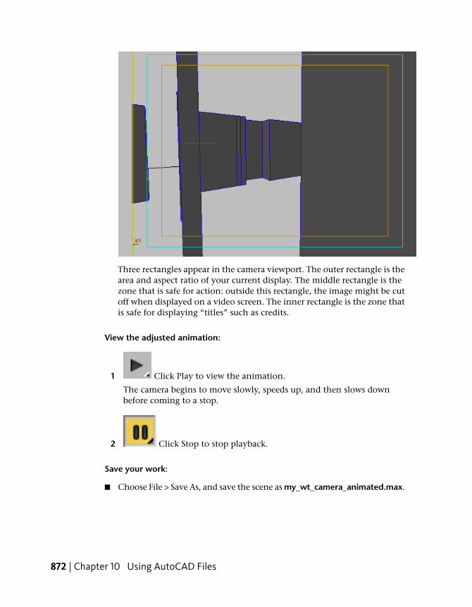
Three rectangles appear in the camera viewport. The outer rectangle is thearea and aspect ratio of your current display. The middle rectangle is thezone that is safe for action: outside this rectangle, the image might be cutoff when displayed on a video screen. The inner rectangle is the zone thatis safe for displaying “titles” such as credits.
View the adjusted animation:
1 Click Play to view the animation.
The camera begins to move slowly, speeds up, and then slows downbefore coming to a stop.
2 Click Stop to stop playback.
Save your work:
■ Choose File > Save As, and save the scene as my_wt_camera_animated.max.
872 | Chapter 10 Using AutoCAD Files
Constructing the Ceiling
To construct the ceiling, you create a polyline shape, and then convert it toa surface.
Set up the scene:
■ Continue from your previous scene, or go to the\using_autocad_files\walkthrough\ folder and open the file wt_camera.max.
Change the view:
1 Click the POV viewport label and choose Top (or press T).
2 Click Zoom Extents.
Set up snaps:
Snaps ensure that the line you create will align with the geometry of the walls.
1 On the main toolbar, choose 3D Snap from the Snaps flyout.
2 Right-click the same 3D Snap button.
A Grid And Snap Settings dialog appears.
Constructing the Ceiling | 873
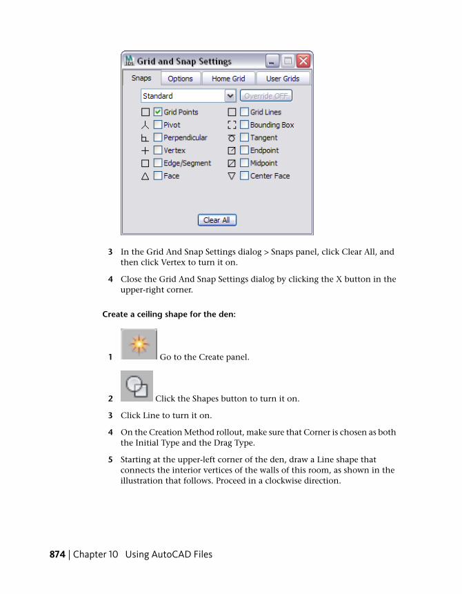
3 In the Grid And Snap Settings dialog > Snaps panel, click Clear All, andthen click Vertex to turn it on.
4 Close the Grid And Snap Settings dialog by clicking the X button in theupper-right corner.
Create a ceiling shape for the den:
1 Go to the Create panel.
2 Click the Shapes button to turn it on.
3 Click Line to turn it on.
4 On the Creation Method rollout, make sure that Corner is chosen as boththe Initial Type and the Drag Type.
5 Starting at the upper-left corner of the den, draw a Line shape thatconnects the interior vertices of the walls of this room, as shown in theillustration that follows. Proceed in a clockwise direction.
874 | Chapter 10 Using AutoCAD Files
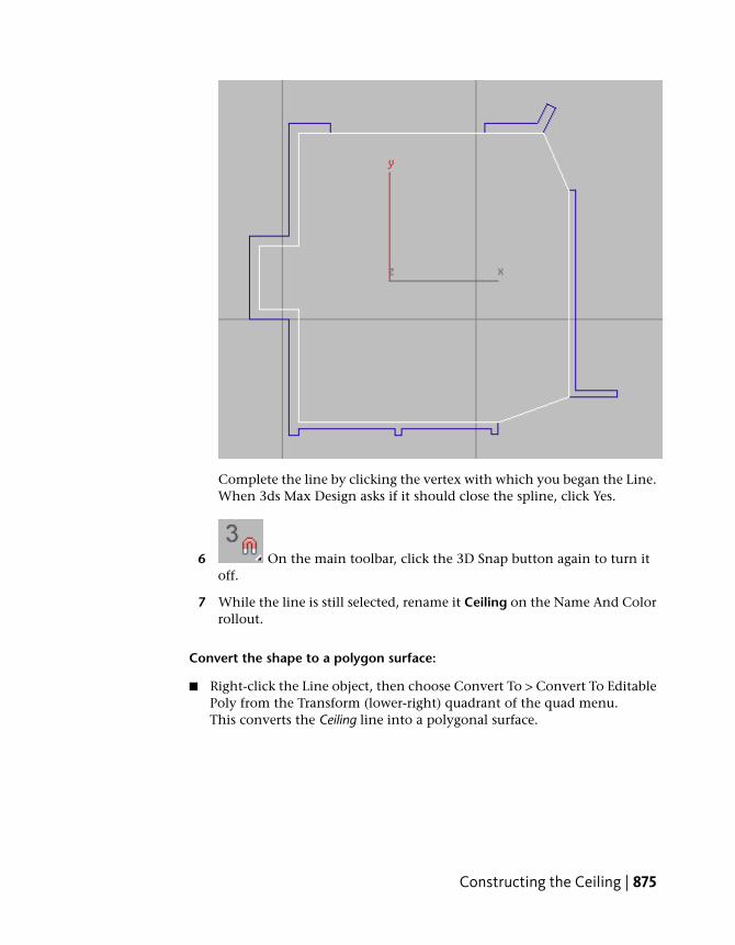
Complete the line by clicking the vertex with which you began the Line.When 3ds Max Design asks if it should close the spline, click Yes.
6 On the main toolbar, click the 3D Snap button again to turn itoff.
7 While the line is still selected, rename it Ceiling on the Name And Colorrollout.
Convert the shape to a polygon surface:
■ Right-click the Line object, then choose Convert To > Convert To EditablePoly from the Transform (lower-right) quadrant of the quad menu.This converts the Ceiling line into a polygonal surface.
Constructing the Ceiling | 875
Correct the normal of the ceiling surface:
1 Go to the Modify panel.
2 Make sure the ceiling is still selected, and then choose Normal from theModifier List drop-down.
3 Make sure Flip Normals is on (it should be on by default).
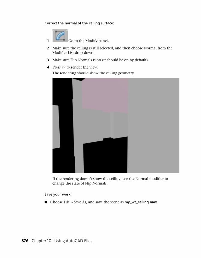
4 Press F9 to render the view.
The rendering should show the ceiling geometry.
If the rendering doesn’t show the ceiling, use the Normal modifier tochange the state of Flip Normals.
Save your work:
■ Choose File > Save As, and save the scene as my_wt_ceiling.max.
876 | Chapter 10 Using AutoCAD Files
Constructing the Floor
To construct the floor, you simply copy the ceiling geometry.
Set up the scene:
■ Continue from your previous scene, or go to the\using_autocad_files\walkthrough\ folder and open the file wt_ceiling.max.
Construct the floor by cloning the ceiling:
1 Click the POV viewport label and choose Left (or press L).
2 Click Zoom Extents.
3 If the ceiling is not still selected, click Select By Name (or pressH) and use the Select From Scene dialog to select it.
4 On the main toolbar, click Select And Move to turn it on.
5 Hold down a Shift key while you drag the ceiling down to floor level.
Shift+move creates a copy of the ceiling object, and when you release themouse, a Clone Options dialog appears.
6 In the Clone Options dialog, choose Copy. Change the name of thecloned object to Floor, and then click OK.
Fix the floor's normal:
The floor faces upwards, so it doesn't need the Normal modifier.
1 Go to the Modify panel.
Constructing the Floor | 877
2 On the modifier stack, make sure the Normal modifier ishighlighted, and then click Remove Modifier From The Stack.
Correct the floor's alignment:
1 Click the Maximize Viewport Toggle (or press Alt+W) to see fourviewports.
2 Activate the CameraDen viewport by right-clicking it.
3 Make sure the floor is still selected, and then on the maintoolbar, click the Align button to turn it on.
4 Click one of the walls.
An Align Selection dialog appears.
5 In the Align Selection dialog, turn off X Position and Y Position. Turnon Z Position. For Current Object choose Center, and for Target Objectchoose Minimum.
878 | Chapter 10 Using AutoCAD Files
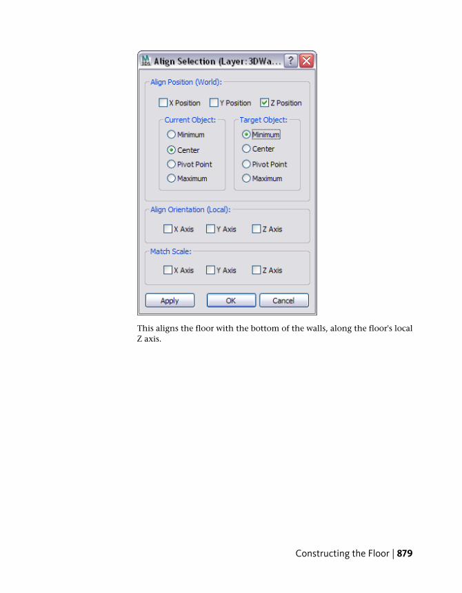
This aligns the floor with the bottom of the walls, along the floor's localZ axis.
Constructing the Floor | 879
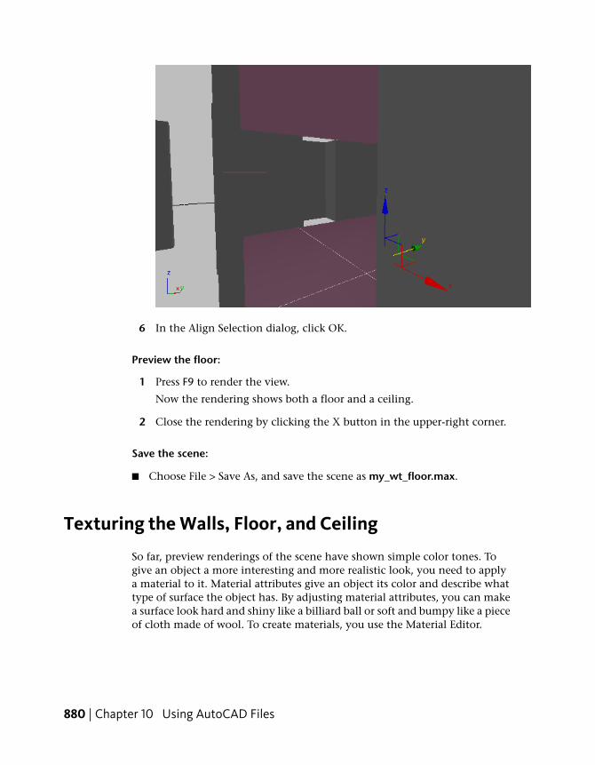
6 In the Align Selection dialog, click OK.
Preview the floor:
1 Press F9 to render the view.
Now the rendering shows both a floor and a ceiling.
2 Close the rendering by clicking the X button in the upper-right corner.
Save the scene:
■ Choose File > Save As, and save the scene as my_wt_floor.max.
Texturing the Walls, Floor, and Ceiling
So far, preview renderings of the scene have shown simple color tones. Togive an object a more interesting and more realistic look, you need to applya material to it. Material attributes give an object its color and describe whattype of surface the object has. By adjusting material attributes, you can makea surface look hard and shiny like a billiard ball or soft and bumpy like a pieceof cloth made of wool. To create materials, you use the Material Editor.
880 | Chapter 10 Using AutoCAD Files
Set up the scene:
■ Continue from your previous scene, or go to the\using_autocad_files\walkthrough\ folder and open the file wt_floor.max.
Create a material for the walls and ceiling:
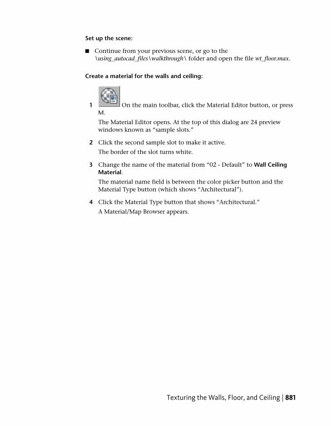
1 On the main toolbar, click the Material Editor button, or pressM.
The Material Editor opens. At the top of this dialog are 24 previewwindows known as “sample slots.”
2 Click the second sample slot to make it active.
The border of the slot turns white.
3 Change the name of the material from “02 - Default” to Wall CeilingMaterial.
The material name field is between the color picker button and theMaterial Type button (which shows “Architectural”).
4 Click the Material Type button that shows “Architectural.”
A Material/Map Browser appears.
Texturing the Walls, Floor, and Ceiling | 881
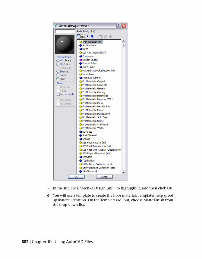
5 In the list, click “Arch & Design (mi)” to highlight it, and then click OK.
6 You will use a template to create the floor material. Templates help speedup material creation. On the Templates rollout, choose Matte Finish fromthe drop-down list.
882 | Chapter 10 Using AutoCAD Files
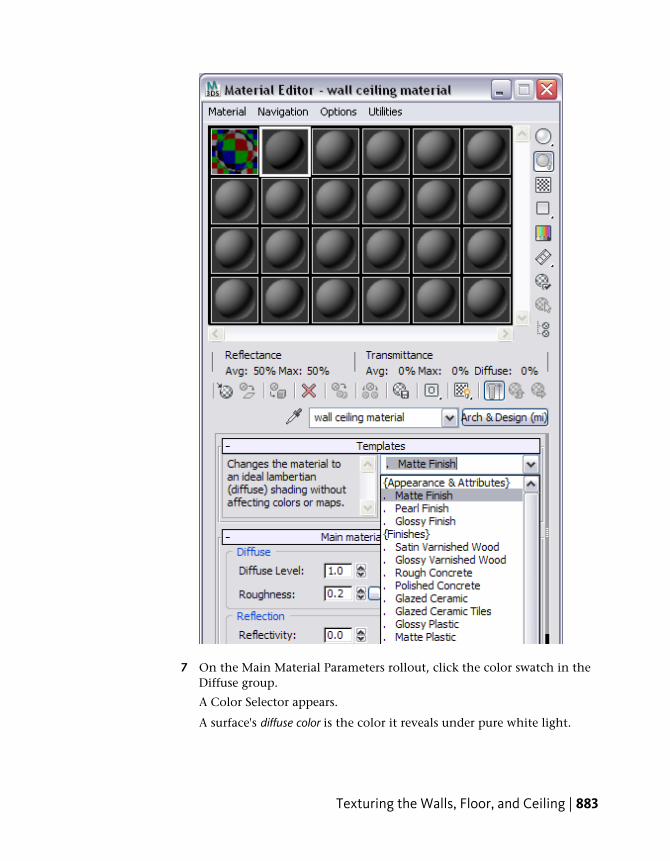
7 On the Main Material Parameters rollout, click the color swatch in theDiffuse group.
A Color Selector appears.
A surface's diffuse color is the color it reveals under pure white light.
Texturing the Walls, Floor, and Ceiling | 883
8 In the Color Selector, assign these values to the color:
■ Hue: 0.19
■ Sat (saturation): 0.2
■ Value: 1.0
Now the paint color is a pale yellow.
9 Click OK to close the Color Selector.
Apply the material to the walls and ceiling:
1 Click Select By Name (or press H) to display a Select From Scenedialog. In the list, click and Ctrl+click to select the wall and ceiling objects,and then click Select.
2 In the Material Editor, click Assign Material To Selection.
3ds Max Design applies the material to the selected objects.
NOTE The sample slot that displays the material now shows white trianglesin each corner: these indicate that the material is being used in the scene.
Create a material for the floor:
The floor material is slightly more complex: you will use a map to display awooden floor effect.
1 Click the third sample slot to make it active.
2 Change the name of this material to Floor Material.
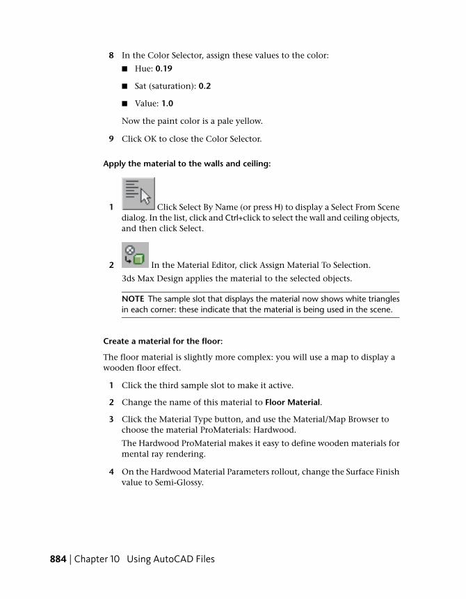
3 Click the Material Type button, and use the Material/Map Browser tochoose the material ProMaterials: Hardwood.
The Hardwood ProMaterial makes it easy to define wooden materials formental ray rendering.
4 On the Hardwood Material Parameters rollout, change the Surface Finishvalue to Semi-Glossy.
884 | Chapter 10 Using AutoCAD Files
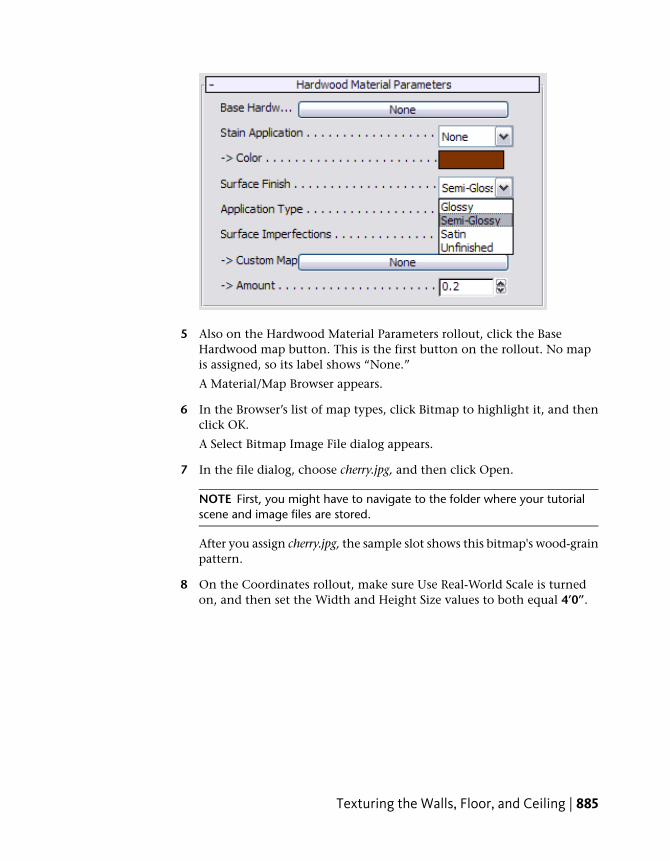
5 Also on the Hardwood Material Parameters rollout, click the BaseHardwood map button. This is the first button on the rollout. No mapis assigned, so its label shows “None.”
A Material/Map Browser appears.
6 In the Browser’s list of map types, click Bitmap to highlight it, and thenclick OK.
A Select Bitmap Image File dialog appears.
7 In the file dialog, choose cherry.jpg, and then click Open.
NOTE First, you might have to navigate to the folder where your tutorialscene and image files are stored.
After you assign cherry.jpg, the sample slot shows this bitmap's wood-grainpattern.
8 On the Coordinates rollout, make sure Use Real-World Scale is turnedon, and then set the Width and Height Size values to both equal 4’0”.
Texturing the Walls, Floor, and Ceiling | 885
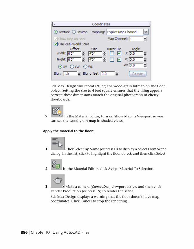
3ds Max Design will repeat (“tile”) the wood-grain bitmap on the floorobject. Setting the size to 4 feet square ensures that the tiling appearscorrect: these dimensions match the original photograph of cherryfloorboards.
9 In the Material Editor, turn on Show Map In Viewport so youcan see the wood-grain map in shaded views.
Apply the material to the floor:
1 Click Select By Name (or press H) to display a Select From Scenedialog. In the list, click to highlight the floor object, and then click Select.
2 In the Material Editor, click Assign Material To Selection.
3 Make a camera (CameraDen) viewport active, and then clickRender Production (or press F9) to render the scene.
3ds Max Design displays a warning that the floor doesn't have mapcoordinates. Click Cancel to stop the rendering.
886 | Chapter 10 Using AutoCAD Files
The floor is an Editable Poly object. By default, object primitives havemapping coordinates assigned to them, but editable surfaces do not.
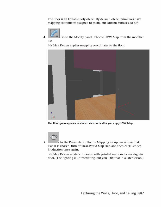
4 Go to the Modify panel. Choose UVW Map from the modifierlist.
3ds Max Design applies mapping coordinates to the floor.
The floor grain appears in shaded viewports after you apply UVW Map.
5 In the Parameters rollout > Mapping group, make sure thatPlanar is chosen, turn off Real-World Map Size, and then click RenderProduction once again.
3ds Max Design renders the scene with painted walls and a wood-grainfloor. (The lighting is uninteresting, but you'll fix that in a later lesson.)
Texturing the Walls, Floor, and Ceiling | 887
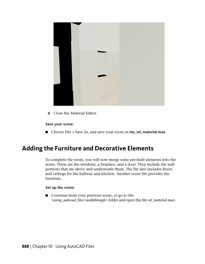
6 Close the Material Editor.
Save your scene:
■ Choose File > Save As, and save your scene as my_wt_material.max.
Adding the Furniture and Decorative Elements
To complete the room, you will now merge some pre-built elements into thescene. These are the windows, a fireplace, and a door. They include the wallportions that are above and underneath them. The file also includes floorsand ceilings for the hallway and kitchen. Another scene file provides thefurniture.
Set up the scene:
■ Continue from your previous scene, or go to the\using_autocad_files\walkthrough\ folder and open the file wt_material.max.
888 | Chapter 10 Using AutoCAD Files
Add the windows, fireplace, and door:
1 From the Application menu, choose Import > Merge. Browseto the \using_autocad_files\walkthrough\ folder, choose the filewt_door_windows.max, and then click Open.
A Merge dialog appears.
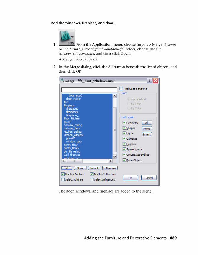
2 In the Merge dialog, click the All button beneath the list of objects, andthen click OK.
The door, windows, and fireplace are added to the scene.
Adding the Furniture and Decorative Elements | 889
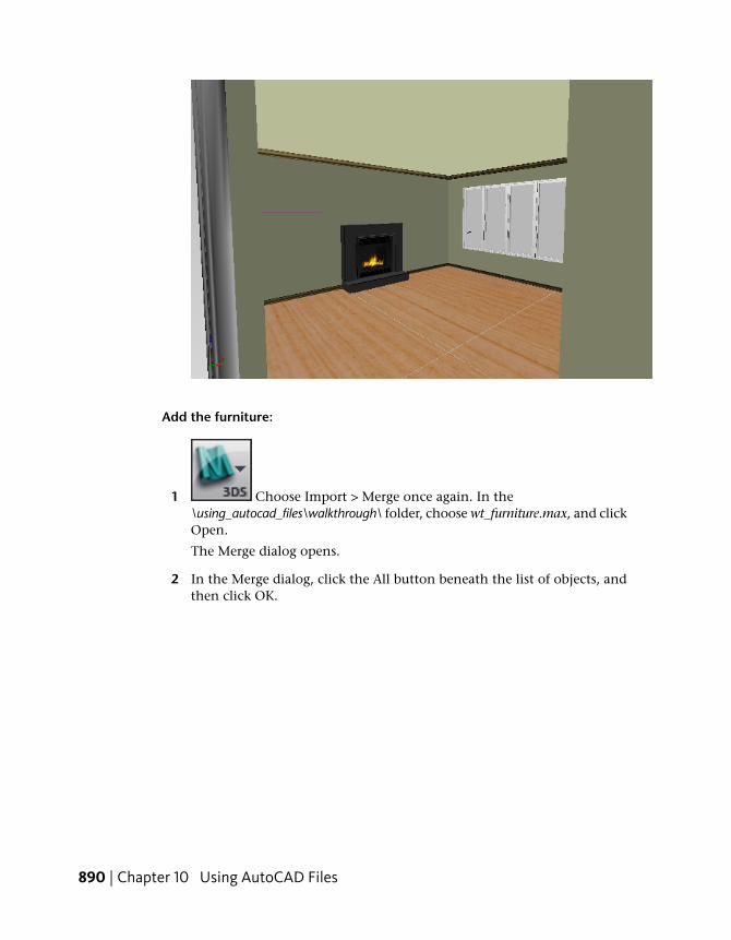
Add the furniture:
1 Choose Import > Merge once again. In the\using_autocad_files\walkthrough\ folder, choose wt_furniture.max, and clickOpen.
The Merge dialog opens.
2 In the Merge dialog, click the All button beneath the list of objects, andthen click OK.
890 | Chapter 10 Using AutoCAD Files
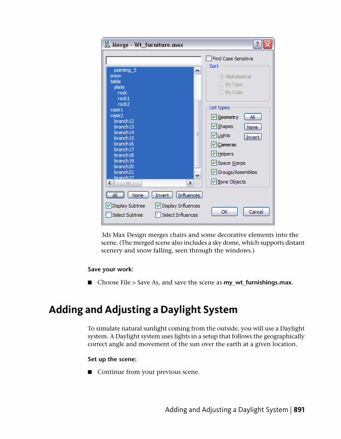
3ds Max Design merges chairs and some decorative elements into thescene. (The merged scene also includes a sky dome, which supports distantscenery and snow falling, seen through the windows.)
Save your work:
■ Choose File > Save As, and save the scene as my_wt_furnishings.max.
Adding and Adjusting a Daylight System
To simulate natural sunlight coming from the outside, you will use a Daylightsystem. A Daylight system uses lights in a setup that follows the geographicallycorrect angle and movement of the sun over the earth at a given location.
Set up the scene:
■ Continue from your previous scene.
Adding and Adjusting a Daylight System | 891
Add the daylight system:
1 Right-click the Perspective viewport to make it active, and thenclick the Maximize Viewport Toggle (or press Alt+W).
TIP If a Perspective viewport is not visible, you can change one of theorthographic views to a Perspective view, but then you will have to navigatein the viewport to get a good overhead view of the house, with some emptyspace around it.
2 Go to the Create panel.
3 Click the Systems button to turn it on.
4 Click the Daylight button to turn it on.
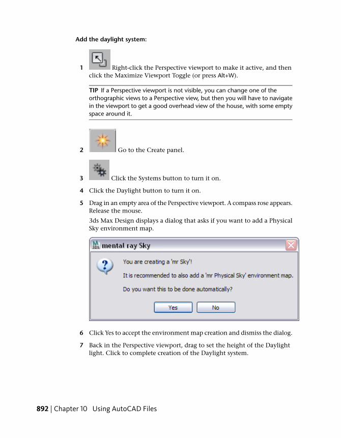
5 Drag in an empty area of the Perspective viewport. A compass rose appears.Release the mouse.
3ds Max Design displays a dialog that asks if you want to add a PhysicalSky environment map.
6 Click Yes to accept the environment map creation and dismiss the dialog.
7 Back in the Perspective viewport, drag to set the height of the Daylightlight. Click to complete creation of the Daylight system.
892 | Chapter 10 Using AutoCAD Files
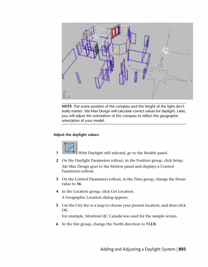
NOTE The scene position of the compass and the height of the light don'treally matter: 3ds Max Design will calculate correct values for daylight. Later,you will adjust the orientation of the compass to reflect the geographicorientation of your model.
Adjust the daylight values:
1 With Daylight still selected, go to the Modify panel.
2 On the Daylight Parameters rollout, in the Position group, click Setup.
3ds Max Design goes to the Motion panel and displays a ControlParameters rollout.
3 On the Control Parameters rollout, in the Time group, change the Hoursvalue to 16.
4 In the Location group, click Get Location.
A Geographic Location dialog appears.
5 Use the City list or a map to choose your present location, and then clickOK.
For example, Montreal QC Canada was used for the sample scenes.
6 In the Site group, change the North direction to 112.0.
Adding and Adjusting a Daylight System | 893
This value corresponds to Montreal. It also ensures that the living roomis oriented to the southwest, toward the setting sun.
If you chose a different city, you might want to use its local value fornorth.
3ds Max Design changes the orientation of the compass to point to thenorth you entered.
Save the scene:
■ Choose File > Save As, and save your scene as my_wt_daylight.max.
Adjusting the Environment
Before you do any renderings, some environment parameters that control theimage results should be set correctly for the current scene.
Set up the scene:
■ Continue from your previous scene, or go to the\using_autocad_files\walkthrough\ folder and open the file wt_daylight.max.
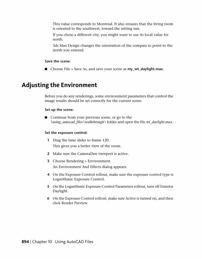
Set the exposure control:
1 Drag the time slider to frame 120.
This gives you a better view of the room.
2 Make sure the CameraDen viewport is active.
3 Choose Rendering > Environment.
An Environment And Effects dialog appears.
4 On the Exposure Control rollout, make sure the exposure control type isLogarithmic Exposure Control.
5 On the Logarithmic Exposure Control Parameters rollout, turn off ExteriorDaylight.
6 On the Exposure Control rollout, make sure Active is turned on, and thenclick Render Preview.
894 | Chapter 10 Using AutoCAD Files
The preview window shows that the scene is dark. This is because therendering shows only direct lighting. It doesn’t show the indirect lightingfrom bounced sunlight that would occur in real life. You will use themental ray renderer to correct this.
Adjusting the Environment | 895
Using the mental ray Renderer
You can use the mental ray renderer to generate indirect lighting, usingbounced daylight to improve the illumination of th scene.
Set up the scene:
■ Continue from your previous scene.
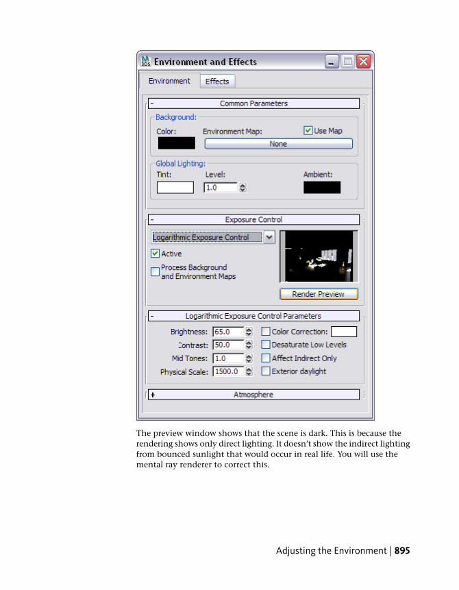
Preview the room:
➤ Make sure the CameraDen viewport is still active, and then clickRender Production (or press F9).
3ds Max Design renders the scene, but hardly any of the room is visibleat all. Sunlight enters through the window, but it doesn't spread throughthe room the way real-life sunlight does.
896 | Chapter 10 Using AutoCAD Files
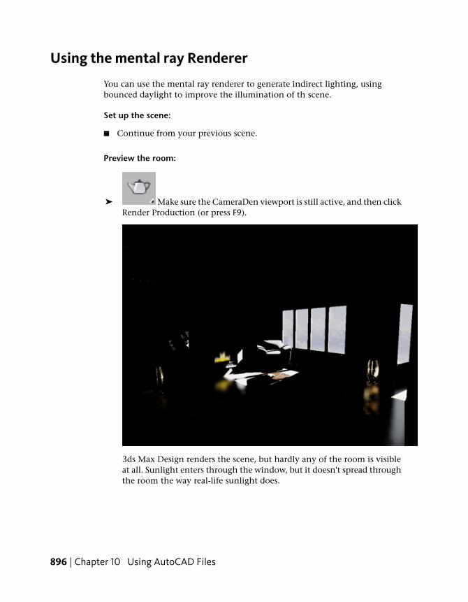
Turn on final gathering:
Final Gather causes light to bounce off surfaces as it does in real life.
1 At the bottom of the Render Scene dialog, drag the Final Gather Precisionslider one notch to the left, so the status changes from “Final GatherDisabled” to “Draft.”
2 In the Trace/Bounces Limits group, set FG Bounces to 2.
3 Click Render.
Now the room is clearly lit by daylight. It is actually a little too well lit.Also, there are some dark patches on the ceiling that are caused byinaccuracies at the Draft level of Final Gather. These are easy to fix.
Using the mental ray Renderer | 897
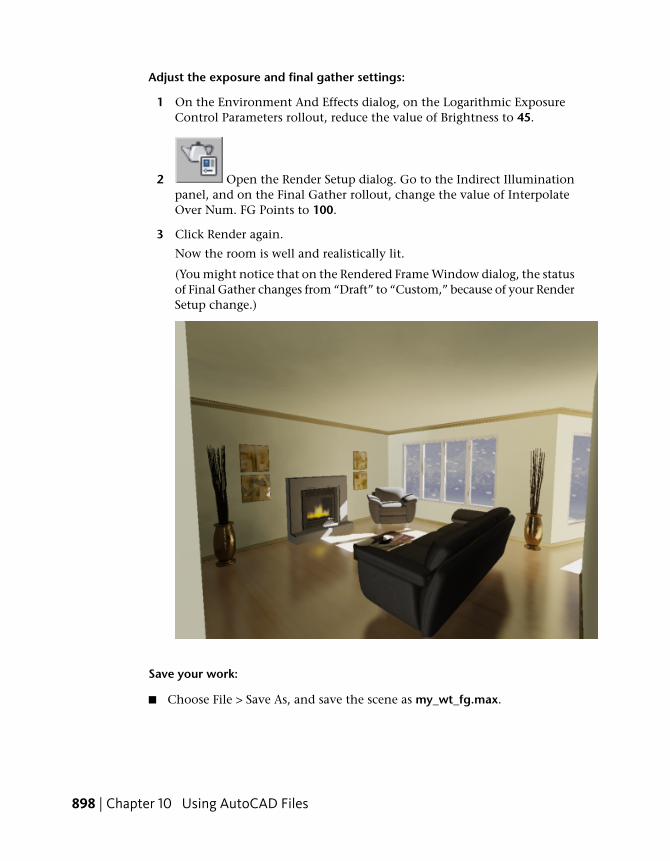
Adjust the exposure and final gather settings:
1 On the Environment And Effects dialog, on the Logarithmic ExposureControl Parameters rollout, reduce the value of Brightness to 45.
2 Open the Render Setup dialog. Go to the Indirect Illuminationpanel, and on the Final Gather rollout, change the value of InterpolateOver Num. FG Points to 100.
3 Click Render again.
Now the room is well and realistically lit.
(You might notice that on the Rendered Frame Window dialog, the statusof Final Gather changes from “Draft” to “Custom,” because of your RenderSetup change.)
Save your work:
■ Choose File > Save As, and save the scene as my_wt_fg.max.
898 | Chapter 10 Using AutoCAD Files
Rendering the Walkthrough Animation
At a resolution of 640 x 480, it can take 1 minute or more to render eachframe, depending on the speed of your computer, so you probably don't wantto render the entire animation: at 200 frames, that would take a few hours ona standalone system. This lesson describes some ways to check your work andpreview what the final result would be.
Set up the scene:
■ Continue from your previous scene, or go to the\using_autocad_files\walkthrough\ folder and open the filewt_finalgather.max.
Render a preview animation:
A preview renders at low resolution, with shading but no rendering effects. Itis a good way to check the animation you've created.
1 From the main menu, choose Animation > Make Preview.
A Make Preview dialog appears.
2 Click Create.
3 Click OK to accept the default Cinepak codec.
3ds Max Design renders the animation as an AVI movie file. As it createsthe preview, 3ds Max Design displays each frame in the viewport. Whenthe preview is done, it launches the Windows Media Player and plays thepreview animation.
You can replay the preview in the Media Player by clicking Play oncemore, or by choosing Animation > View Preview in 3ds Max Design.
The preview gives you a precise idea of the speed and rhythm of theanimation, and lets you see if there is anything you need to fix. At thispoint, you might want to make adjustments by changing the camera'starget position or the shape of the path.
Rendering the Walkthrough Animation | 899
Render sample frames:
While the preview shows the animation's speed and rhythm, it doesn't showhow frames look when fully rendered. To get a better idea of the look of theanimation, you can render sample frames.
1 Click Render Setup (or press F10) to display the Render Setupdialog.
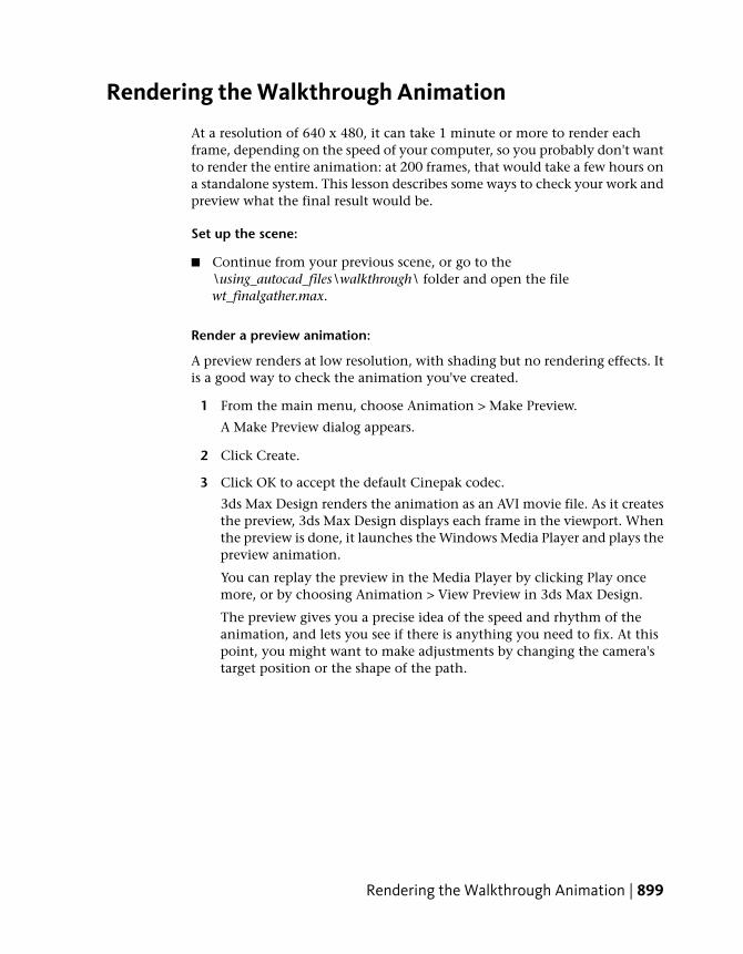
2 On the Common panel, in the Common Parameters rollout, find theTime Output group. Change the output from Single to Active Timesegment, and then change Every Nth Frame to 50.
This will render five frames that are sampled along the duration of theanimation, from frame 0 to frame 200. (Rendering five frames will takeprobably 5 to 10 minutes: adjust the Every Nth Frame value to suit thetime you want to spend on this lesson.)
You need to specify an animation file for the rendering.
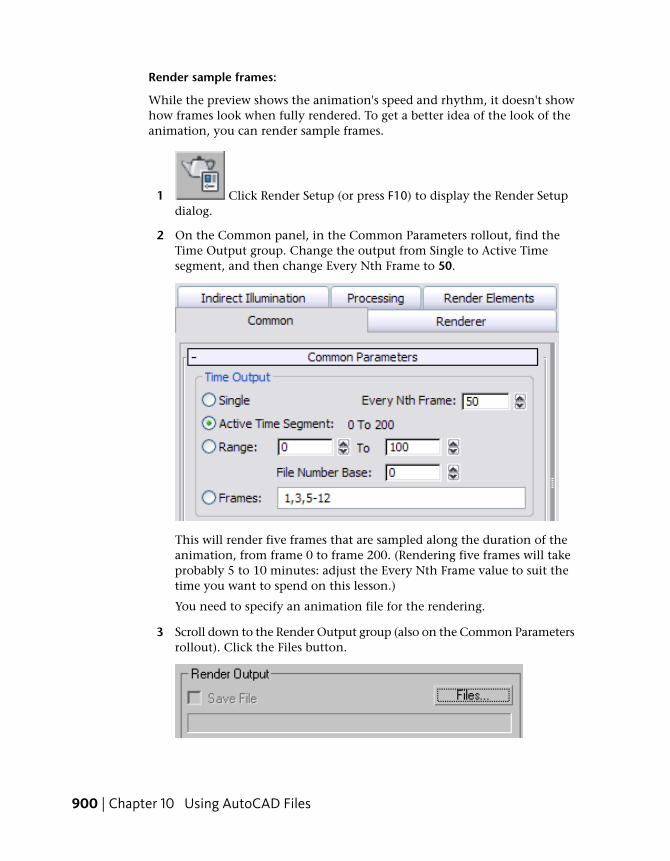
3 Scroll down to the Render Output group (also on the Common Parametersrollout). Click the Files button.
900 | Chapter 10 Using AutoCAD Files
A Render Output File dialog appears.
4 In the file dialog, enter wt_samples as the File Name, and then choose“JPEG File (*.jpg,*.jpe,*.jpeg)” from the Save As Type drop-down list.
When you render an animation to a still-image file type such as JPEG,3ds Max Design creates a sequence of image files. Each has the file nameyou chose (wt_samples) followed by a sequence number (for example,wt_samples0000.jpg).
TIP Leave the folder name set to \renderoutput. The \renderoutput folder isa sub-folder of the 3ds Max Design tutorials project folder.
5 Click Save.
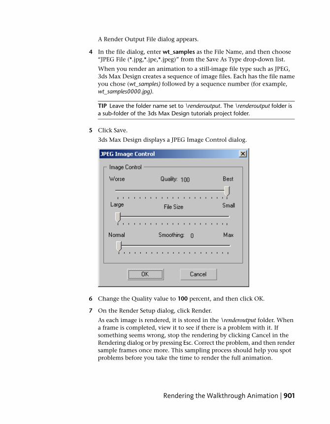
3ds Max Design displays a JPEG Image Control dialog.
6 Change the Quality value to 100 percent, and then click OK.
7 On the Render Setup dialog, click Render.
As each image is rendered, it is stored in the \renderoutput folder. Whena frame is completed, view it to see if there is a problem with it. Ifsomething seems wrong, stop the rendering by clicking Cancel in theRendering dialog or by pressing Esc. Correct the problem, and then rendersample frames once more. This sampling process should help you spotproblems before you take the time to render the full animation.
Rendering the Walkthrough Animation | 901
When you are ready to render a full animation, change the output file typeto a movie format. AVI and MOV are both available options. 3ds MaxDesignprompts you to choose a compressor/decompressor (codec) for themovie. Change Every Nth Frame back to 1, and then render the completeanimation.
You can view a sample AVI movie of the walkthrough by choosing Rendering> View Image File, and from the tutorials folder opening\sceneassets\renderassets\wt.avi.
A final version of the scene is in the \using_autocad_files\walkthrough\ folder,saved as wt_final.max.
Summary
In this tutorial, you learned about basing a model and animation on importedAutoCAD geometry.
Using File Link with AutoCAD DrawingsAs you experienced in the previous lessons, the Import functionality of 3dsMax Design allows you to load drawings and models that were created withAutoCAD, AutoCAD Architecture, or AutoCAD Mechanical. A drawing ormodel is imported and you can begin making alterations using the tools in3ds Max Design.
Importing is fine for a drawing or model that is no longer being updated, butwhat about a drawing that is still being developed? Architectural drawingscan change greatly in a matter of hours, so if you're building a 3D model basedon an imported drawing that is still in flux, you will find yourself changingand rebuilding many objects before the project is finished. Perhaps, completelystarting over if the drawings change a lot.
This is a situation where using the File Link Manager is invaluable. This lessonwill show you the advantages of the tool and how it will save modeling time.
Set up the lesson:
1 Start AutoCAD and choose File menu > Open.
2 Browse to the import\AutoCAD_files\ folder and openww_cad_drawing2link.dwg.
902 | Chapter 10 Using AutoCAD Files
3 If you see the Proxy Information dialog, it means there are custom objectsin the drawing that require special Object Enablers if you plan to editthem. Click OK for now.
4 Choose File menu > Save As and save the drawing as mydrawing2link.dwgto the import\AutoCAD_files\ folder.
This is to preserve the original drawing so the tutorial can be easilyrepeated.
5 Minimize the AutoCAD window.
Make the link:
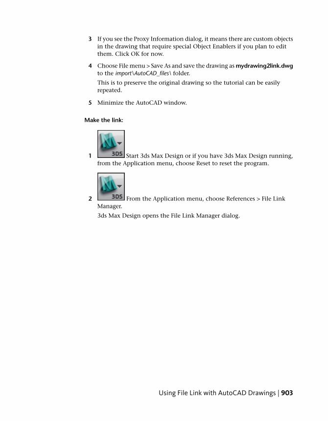
1 Start 3ds Max Design or if you have 3ds Max Design running,from the Application menu, choose Reset to reset the program.
2 From the Application menu, choose References > File LinkManager.
3ds Max Design opens the File Link Manager dialog.
Using File Link with AutoCAD Drawings | 903
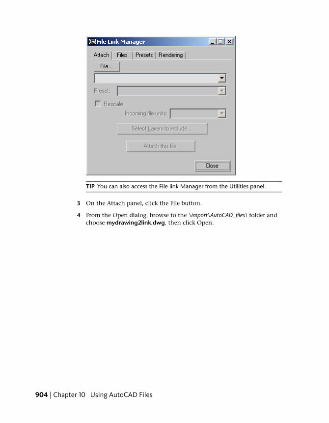
TIP You can also access the File link Manager from the Utilities panel.
3 On the Attach panel, click the File button.
4 From the Open dialog, browse to the \import\AutoCAD_files\ folder andchoose mydrawing2link.dwg. then click Open.
904 | Chapter 10 Using AutoCAD Files
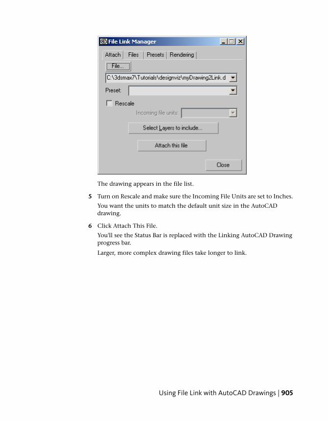
The drawing appears in the file list.
5 Turn on Rescale and make sure the Incoming File Units are set to Inches.
You want the units to match the default unit size in the AutoCADdrawing.
6 Click Attach This File.
You'll see the Status Bar is replaced with the Linking AutoCAD Drawingprogress bar.
Larger, more complex drawing files take longer to link.
Using File Link with AutoCAD Drawings | 905
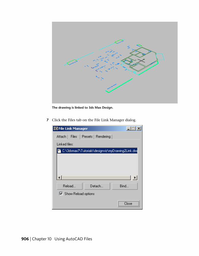
The drawing is linked to 3ds Max Design.
7 Click the Files tab on the File Link Manager dialog.
906 | Chapter 10 Using AutoCAD Files
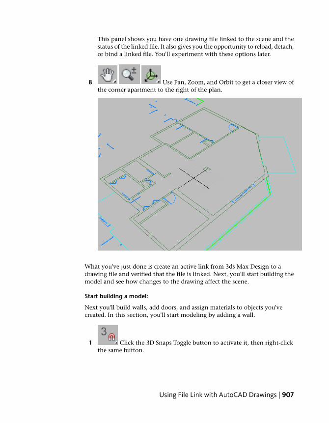
This panel shows you have one drawing file linked to the scene and thestatus of the linked file. It also gives you the opportunity to reload, detach,or bind a linked file. You'll experiment with these options later.
8 Use Pan, Zoom, and Orbit to get a closer view ofthe corner apartment to the right of the plan.
What you've just done is create an active link from 3ds Max Design to adrawing file and verified that the file is linked. Next, you'll start building themodel and see how changes to the drawing affect the scene.
Start building a model:
Next you'll build walls, add doors, and assign materials to objects you'vecreated. In this section, you'll start modeling by adding a wall.
1 Click the 3D Snaps Toggle button to activate it, then right-clickthe same button.
Using File Link with AutoCAD Drawings | 907
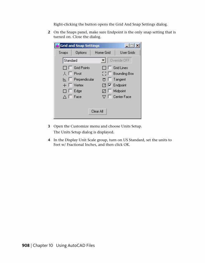
Right-clicking the button opens the Grid And Snap Settings dialog.
2 On the Snaps panel, make sure Endpoint is the only snap setting that isturned on. Close the dialog.
3 Open the Customize menu and choose Units Setup.
The Units Setup dialog is displayed.
4 In the Display Unit Scale group, turn on US Standard, set the units toFeet w/ Fractional Inches, and then click OK.
908 | Chapter 10 Using AutoCAD Files
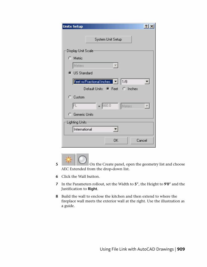
5 On the Create panel, open the geometry list and chooseAEC Extended from the drop-down list.
6 Click the Wall button.
7 In the Parameters rollout, set the Width to 5”, the Height to 9'0” and theJustification to Right.
8 Build the wall to enclose the kitchen and then extend to where thefireplace wall meets the exterior wall at the right. Use the illustration asa guide.
Using File Link with AutoCAD Drawings | 909
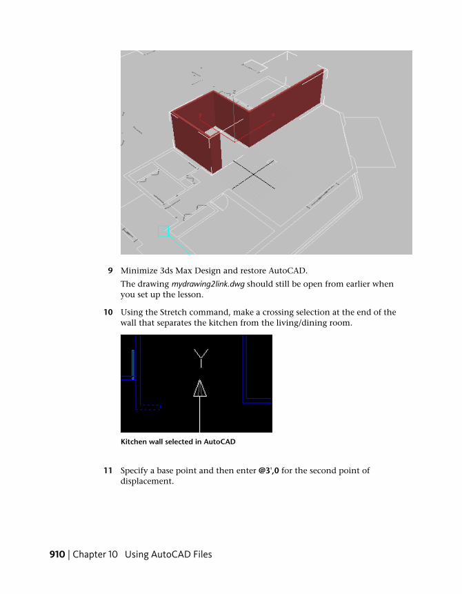
9 Minimize 3ds Max Design and restore AutoCAD.
The drawing mydrawing2link.dwg should still be open from earlier whenyou set up the lesson.
10 Using the Stretch command, make a crossing selection at the end of thewall that separates the kitchen from the living/dining room.
Kitchen wall selected in AutoCAD
11 Specify a base point and then enter @3',0 for the second point ofdisplacement.
910 | Chapter 10 Using AutoCAD Files
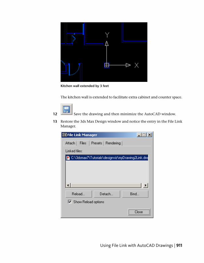
Kitchen wall extended by 3 feet
The kitchen wall is extended to facilitate extra cabinet and counter space.
12 Save the drawing and then minimize the AutoCAD window.
13 Restore the 3ds Max Design window and notice the entry in the File LinkManager.
Using File Link with AutoCAD Drawings | 911
The red flag in the document symbol next to the linked file indicates achange has occurred in the master drawing.
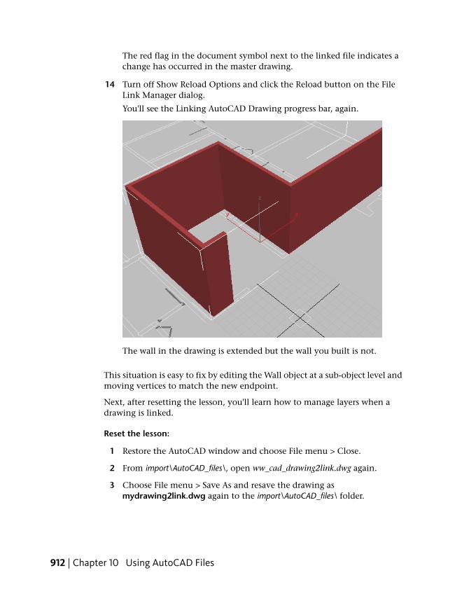
14 Turn off Show Reload Options and click the Reload button on the FileLink Manager dialog.
You'll see the Linking AutoCAD Drawing progress bar, again.
The wall in the drawing is extended but the wall you built is not.
This situation is easy to fix by editing the Wall object at a sub-object level andmoving vertices to match the new endpoint.
Next, after resetting the lesson, you'll learn how to manage layers when adrawing is linked.
Reset the lesson:
1 Restore the AutoCAD window and choose File menu > Close.
2 From import\AutoCAD_files\, open ww_cad_drawing2link.dwg again.
3 Choose File menu > Save As and resave the drawing asmydrawing2link.dwg again to the import\AutoCAD_files\ folder.
912 | Chapter 10 Using AutoCAD Files
4 Click Yes when asked if you want to save over the existing file.
5 Minimize the AutoCAD window.
Manage layers:
In this section, you'll work on a scene that already has a drawing linked, butyou're going to use some of the layer-management features of the File LinkManager.
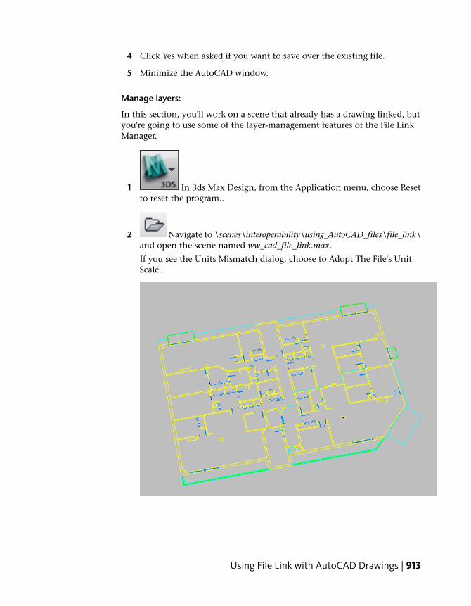
1 In 3ds Max Design, from the Application menu, choose Resetto reset the program..
2 Navigate to \scenes\interoperability\using_AutoCAD_files\file_link\and open the scene named ww_cad_file_link.max.
If you see the Units Mismatch dialog, choose to Adopt The File's UnitScale.
Using File Link with AutoCAD Drawings | 913
This scene already has a drawing file linked to it, but one of the layersyou need was frozen in AutoCAD and by default, frozen layers do notlink unless you specify them.
3 Go to the Utilities panel. Click the More button, and open theFile Link Manager. On the File Link Manager dialog, click the Files tab ifthe Files panel is not active.
NOTE If you see a question mark (?) displayed next to the linked file's namein the File Link Manager, it means that the linked file is “lost”. In this situation,you should click the file name and then click the folder icon to browse forthe “lost” file. This can happen, for example, if you move the location of thetutorial project folder.
4 On the Files panel, make sure Show Reload Options is turned on, thenclick the Reload button.
The File Link Settings dialog appears.
914 | Chapter 10 Using AutoCAD Files
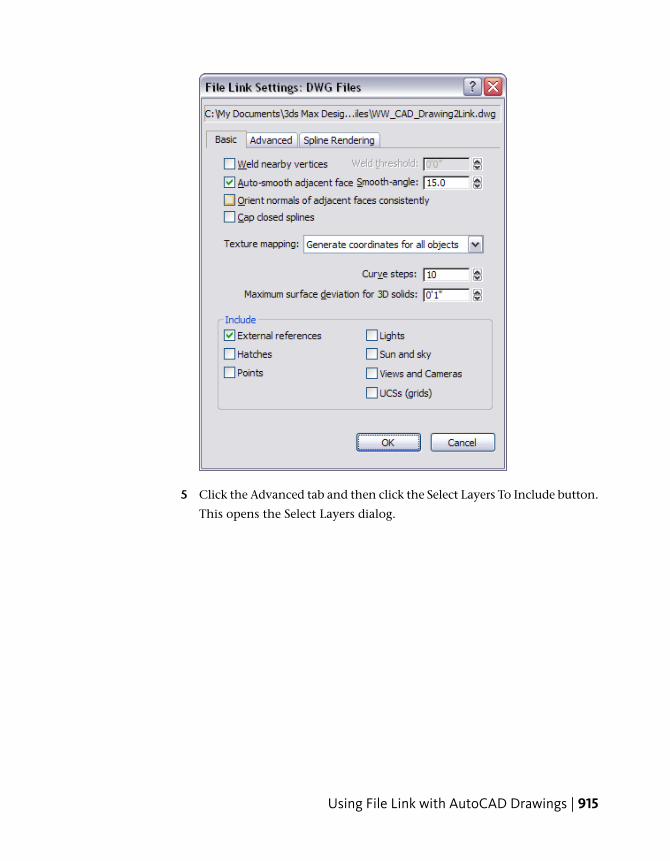
5 Click the Advanced tab and then click the Select Layers To Include button.
This opens the Select Layers dialog.
Using File Link with AutoCAD Drawings | 915
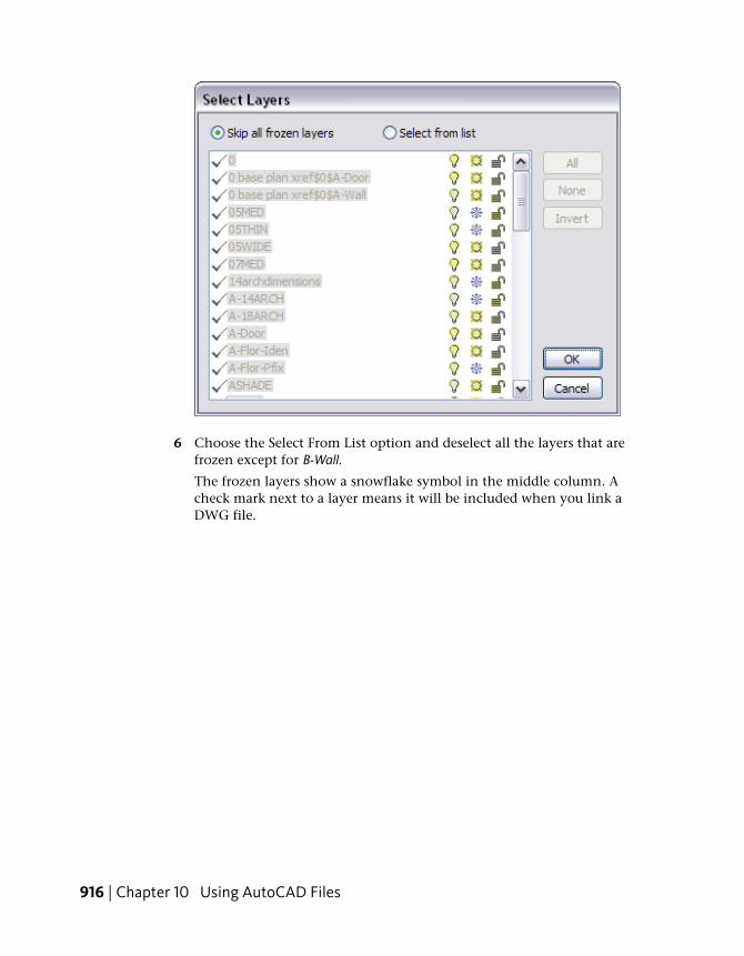
6 Choose the Select From List option and deselect all the layers that arefrozen except for B-Wall.
The frozen layers show a snowflake symbol in the middle column. Acheck mark next to a layer means it will be included when you link aDWG file.
916 | Chapter 10 Using AutoCAD Files
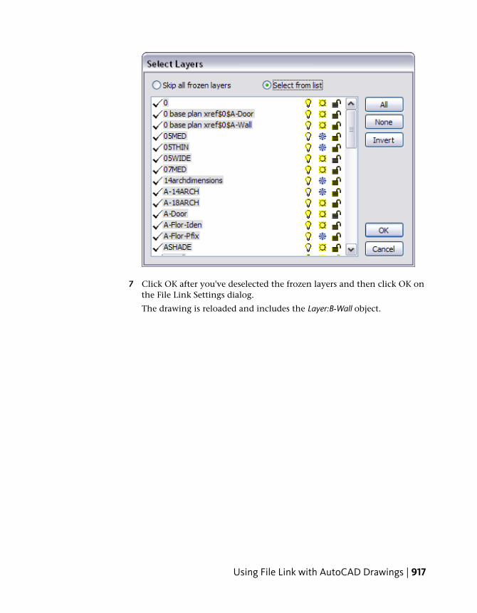
7 Click OK after you've deselected the frozen layers and then click OK onthe File Link Settings dialog.
The drawing is reloaded and includes the Layer:B-Wall object.
Using File Link with AutoCAD Drawings | 917
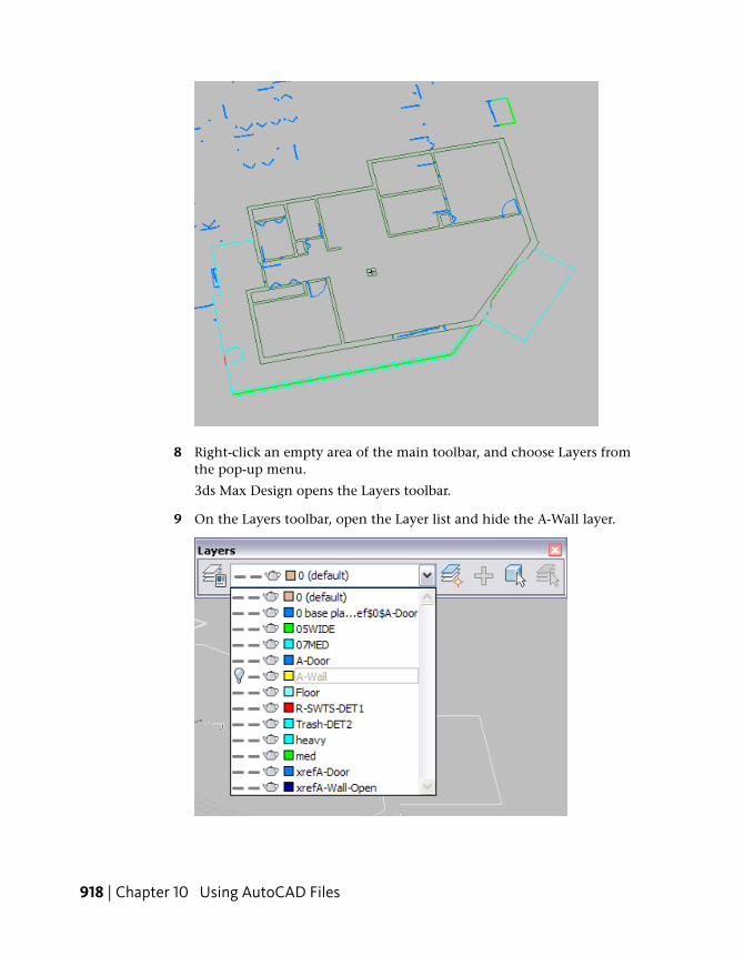
8 Right-click an empty area of the main toolbar, and choose Layers fromthe pop-up menu.
3ds Max Design opens the Layers toolbar.
9 On the Layers toolbar, open the Layer list and hide the A-Wall layer.
918 | Chapter 10 Using AutoCAD Files
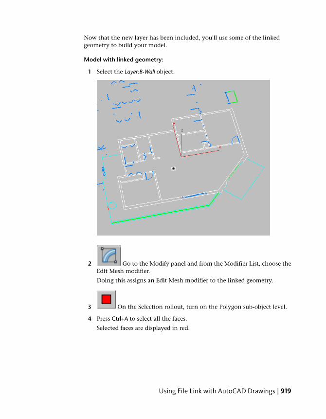
Now that the new layer has been included, you'll use some of the linkedgeometry to build your model.
Model with linked geometry:
1 Select the Layer:B-Wall object.
2 Go to the Modify panel and from the Modifier List, choose theEdit Mesh modifier.
Doing this assigns an Edit Mesh modifier to the linked geometry.
3 On the Selection rollout, turn on the Polygon sub-object level.
4 Press Ctrl+A to select all the faces.
Selected faces are displayed in red.
Using File Link with AutoCAD Drawings | 919
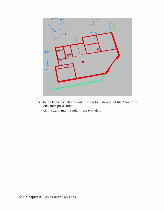
5 In the Edit Geometry rollout, turn on Extrude and set the Amount to9'0”, then press Enter.
All the walls and the column are extruded.
920 | Chapter 10 Using AutoCAD Files
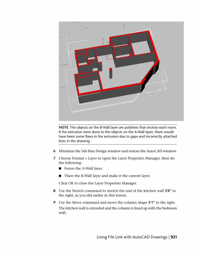
NOTE The objects on the B-Wall layer are polylines that enclose each room.If the extrusion were done to the objects on the A-Wall layer, there wouldhave been some flaws in the extrusion due to gaps and incorrectly attachedlines in the drawing.
6 Minimize the 3ds Max Design window and restore the AutoCAD window.
7 Choose Format > Layer to open the Layer Properties Manager, then dothe following:
■ Freeze the A-Wall layer.
■ Thaw the B-Wall layer and make it the current layer.
Click OK to close the Layer Properties Manager.
8 Use the Stretch command to stretch the end of the kitchen wall 3'0” tothe right, as you did earlier in this lesson.
9 Use the Move command and move the column shape 5'1” to the right.
The kitchen wall is extended and the column is lined up with the bedroomwall.
Using File Link with AutoCAD Drawings | 921
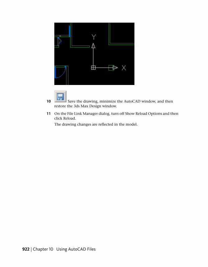
10 Save the drawing, minimize the AutoCAD window, and thenrestore the 3ds Max Design window.
11 On the File Link Manager dialog, turn off Show Reload Options and thenclick Reload.
The drawing changes are reflected in the model.
922 | Chapter 10 Using AutoCAD Files
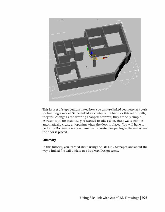
This last set of steps demonstrated how you can use linked geometry as a basisfor building a model. Since linked geometry is the basis for this set of walls,they will change as the drawing changes; however, they are only simpleextrusions. If, for instance, you wanted to add a door, these walls will notautomatically create an opening when the door is placed. You will have toperform a Boolean operation to manually create the opening in the wall wherethe door is placed.
Summary
In this tutorial, you learned about using the File Link Manager, and about theway a linked file will update in a 3ds Max Design scene.
Using File Link with AutoCAD Drawings | 923