Embed Size (px)
Citation preview
Dielectric • 22 Tower Rd., Raymond, ME 04071 USA • +1 207-655-8100 • www.dielectric.com • TVPlanner07/2013 1
TV Planner-process colors:9998_DTV Brochure_2003 7/29/13 1:29 PM Page 1
Dielectric • 22 Tower Rd., Raymond, ME 04071 USA • +1 207-655-8100 • www.dielectric.com • TVPlanner07/2013 1
Dielectric Communications:
Full System Solutions
Since our inception in 1942, we have considered ourselves a solutions oriented engineering company, priding ourselves on our depth of scientificexperience and knowledge. Clients approach us with broadcast needs and wedeliver full system solutions, jointly tasking with client engineering staff designtechnologically advanced systems. We design and manufacture full broadcastsystems from the transmitter output to the tower top.
A Culture of innovation spanning over seven decades.
Dielectric’s leadership in passive RF technologies is reflected in the expertisewe offer and the recognition we’ve received: over 100 patents, 2 emmys fortechnical innovation, 4 NAB Pick hits, to name a few.
Dielectric offers the customized support services and planning tools you needto build your television antenna from configuring a new antenna system, toacquiring knowledgeable insights into specific technical issues, Dielectricresources provide easy access to the assistance you needed. This includescustomized support services, as well as planning tools to guide in the design.
Call Us
This fifth edition of our television planning guide details the systems and components we produce. Call us about your requirements or any of our broad-cast products at 1-800-341-9678.
Advancing the frontier in broadcast communications for over sevendecades.
Specifications subject to change without notice.
Products contained in this catalog may be covered by one or more of the following patents: 6,917,264; 6,903,624;6,887,093; 6,882,224; 6,870,443; 6,867,743; 6,816,040; 6,703,984; 6,703,911; 6,677,916; 6,650,300; 6,650,209;6,617,940; 6,538,529; 6,373,444; 6,320,555; 5,999,145; 5,861,858; 5,455,548; 5,418,545; 5,401,173; 5,167,510;4,988,961; 4,951,013; 4,899,165; 4,723,307; 4,654,962; 4,602,227. Additional patents are pending.
TV Planner-process colors:9998_DTV Brochure_2003 7/29/13 1:29 PM Page 1
Dielectric • 22 Tower Rd., Raymond, ME 04071 USA • +1 207-655-8100 • www.dielectric.com • TVPlanner07/2013 2
Table of Contents
Top Mounted Antenna SystemsUHF
TFU Series . . . . . . . . . . . . . . . . . . . . . . . . . . . . . . . . . . . . . . . . . . . . . . . . . . . . . . . .3TU Series . . . . . . . . . . . . . . . . . . . . . . . . . . . . . . . . . . . . . . . . . . . . . . . . . . . . . . . . .5
VHFTW Series . . . . . . . . . . . . . . . . . . . . . . . . . . . . . . . . . . . . . . . . . . . . . . . . . . . . . . . .14THV Series . . . . . . . . . . . . . . . . . . . . . . . . . . . . . . . . . . . . . . . . . . . . . . . . . . . . . . .17TF Series . . . . . . . . . . . . . . . . . . . . . . . . . . . . . . . . . . . . . . . . . . . . . . . . . . . . . . . .19
UHF and VHFTUV Dualband Series . . . . . . . . . . . . . . . . . . . . . . . . . . . . . . . . . . . . . . . . . . . .20Stacked Arrays . . . . . . . . . . . . . . . . . . . . . . . . . . . . . . . . . . . . . . . . . . . . . . . . . . .22
Side Mounted Antenna SystemsUHF
TFU Series . . . . . . . . . . . . . . . . . . . . . . . . . . . . . . . . . . . . . . . . . . . . . . . . . . . . . .25TFU-TC Series . . . . . . . . . . . . . . . . . . . . . . . . . . . . . . . . . . . . . . . . . . . . . . . . . . .29TU Series . . . . . . . . . . . . . . . . . . . . . . . . . . . . . . . . . . . . . . . . . . . . . . . . . . . . . . . .33
VHFTH Series . . . . . . . . . . . . . . . . . . . . . . . . . . . . . . . . . . . . . . . . . . . . . . . . . . . . . . . .31TLS-V Series . . . . . . . . . . . . . . . . . . . . . . . . . . . . . . . . . . . . . . . . . . . . . . . . . . . . .34
TV Planner-process colors:9998_DTV Brochure_2003 7/29/13 1:29 PM Page 2
Dielectric • 22 Tower Rd., Raymond, ME 04071 USA • +1 207-655-8100 • www.dielectric.com • TVPlanner07/2013 3
Top Mounted Antenna Systems—UHF
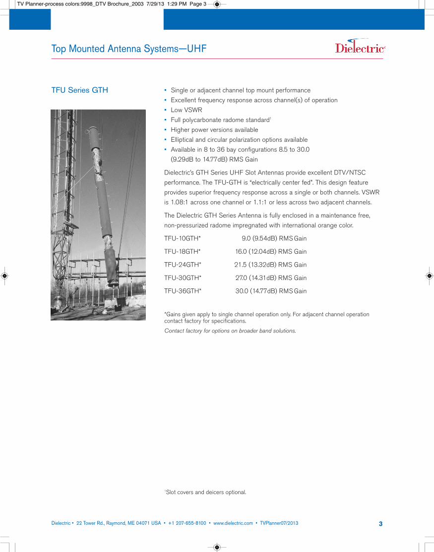
TFU Series GTH • Single or adjacent channel top mount performance• Excellent frequency response across channel(s) of operation• Low VSWR• Full polycarbonate radome standard1
• Higher power versions available• Elliptical and circular polarization options available• Available in 8 to 36 bay configurations 8.5 to 30.0 (9.29dB to 14.77dB) RMS Gain
Dielectric’s GTH Series UHF Slot Antennas provide excellent DTV/NTSC performance. The TFU-GTH is “electrically center fed”. This design feature provides superior frequency response across a single or both channels. VSWRis 1.08:1 across one channel or 1.1:1 or less across two adjacent channels.
The Dielectric GTH Series Antenna is fully enclosed in a maintenance free,non-pressurized radome impregnated with international orange color.
TFU-10GTH* 9.0 (9.54dB) RMS Gain
TFU-18GTH* 16.0 (12.04dB) RMS Gain
TFU-24GTH* 21.5 (13.32dB) RMS Gain
TFU-30GTH* 27.0 (14.31dB) RMS Gain
TFU-36GTH* 30.0 (14.77dB) RMS Gain
*Gains given apply to single channel operation only. For adjacent channel operation contact factory for specifications.
Contact factory for options on broader band solutions.
1Slot covers and deicers optional.
TV Planner-process colors:9998_DTV Brochure_2003 7/29/13 1:29 PM Page 3
Dielectric • 22 Tower Rd., Raymond, ME 04071 USA • +1 207-655-8100 • www.dielectric.com • TVPlanner07/2013 4
Top Mounted Antenna Systems—UHF
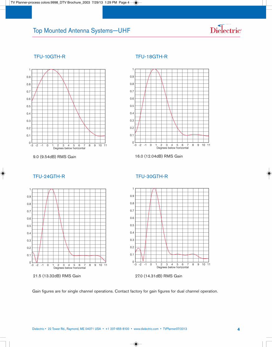
TFU-10GTH-R TFU-18GTH-R
1
0.9
0.8
0.7
0.6
0.5
0.4
0.3
0.2
0.1
0-3 -2 -1 0 1 2 3 4 5 6 7 8 9 10 11
Degrees below horizontal
1
0.9
0.8
0.7
0.6
0.5
0.4
0.3
0.2
0.1
0-3 -2 -1 0 1 2 3 4 5 6 7 8 9 10 11
Degrees below horizontal
TFU-24GTH-R TFU-30GTH-R
1
0.9
0.8
0.7
0.6
0.5
0.4
0.3
0.2
0.1
0-3 -2 -1 0 1 2 3 4 5 6 7 8 9 10 11
Degrees below horizontal
1
0.9
0.8
0.7
0.6
0.5
0.4
0.3
0.2
0.1
0-3 -2 -1 0 1 2 3 4 5 6 7 8 9 10 11
Degrees below horizontal
9.0 (9.54dB) RMS Gain 16.0 (12.04dB) RMS Gain
21.5 (13.32dB) RMS Gain 27.0 (14.31dB) RMS Gain
Gain figures are for single channel operations. Contact factory for gain figures for dual channel operation.
TV Planner-process colors:9998_DTV Brochure_2003 7/29/13 1:29 PM Page 4
Dielectric • 22 Tower Rd., Raymond, ME 04071 USA • +1 207-655-8100 • www.dielectric.com • TVPlanner07/2013 5
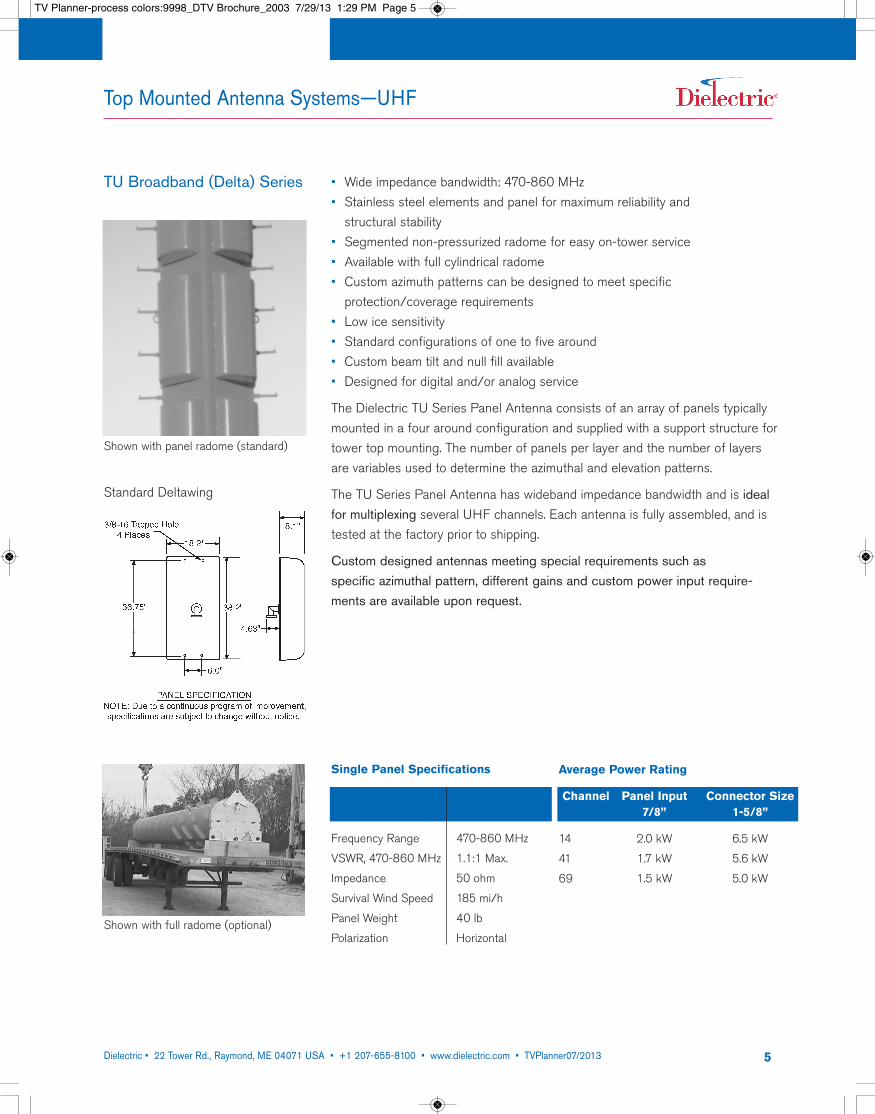
TU Broadband (Delta) Series • Wide impedance bandwidth: 470-860 MHz• Stainless steel elements and panel for maximum reliability and structural stability
• Segmented non-pressurized radome for easy on-tower service• Available with full cylindrical radome• Custom azimuth patterns can be designed to meet specific protection/coverage requirements
• Low ice sensitivity• Standard configurations of one to five around• Custom beam tilt and null fill available• Designed for digital and/or analog service
The Dielectric TU Series Panel Antenna consists of an array of panels typicallymounted in a four around configuration and supplied with a support structure fortower top mounting. The number of panels per layer and the number of layersare variables used to determine the azimuthal and elevation patterns.
The TU Series Panel Antenna has wideband impedance bandwidth and is idealfor multiplexing several UHF channels. Each antenna is fully assembled, and istested at the factory prior to shipping.
Custom designed antennas meeting special requirements such as specific azimuthal pattern, different gains and custom power input require-ments are available upon request.
Single Panel Specifications
Frequency Range 470-860 MHz
VSWR, 470-860 MHz 1.1:1 Max.
Impedance 50 ohm
Survival Wind Speed 185 mi/h
Panel Weight 40 lb
Polarization Horizontal
Average Power Rating
Channel Panel Input Connector Size7/8” 1-5/8”
14 2.0 kW 6.5 kW
41 1.7 kW 5.6 kW
69 1.5 kW 5.0 kW
Standard Deltawing
Top Mounted Antenna Systems—UHF
Shown with panel radome (standard)
Shown with full radome (optional)
,
TV Planner-process colors:9998_DTV Brochure_2003 7/29/13 1:29 PM Page 5
Dielectric • 22 Tower Rd., Raymond, ME 04071 USA • +1 207-655-8100 • www.dielectric.com • TVPlanner07/2013 6
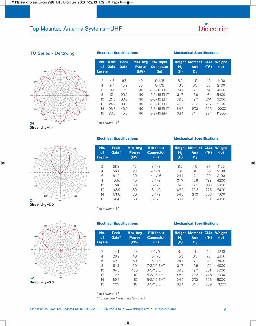
TU Series - Deltawing Electrical Specifications Mechanical Specifications
No. RMS Peak Max Avg EIA Input Height Moment CfAc Weightof Gain* Gain* Power Connector H2 Arm (ft2) (lb)
Layers (kW) (in) (ft) D1
2 4.8 6.7 40 6-1/8 8.9 4.5 46 14004 9.4 13.2 60 6-1/8 16.5 8.3 83 27006 14.0 19.6 110 8-3/16 EHT 24.1 12.1 120 40008 17.1 23.9 110 8-3/16 EHT 31.7 15.9 164 540010 21.6 30.2 110 8-3/16 EHT 39.3 19.7 214 680012 24.2 33.9 110 8-3/16 EHT 46.9 23.5 267 820014 28.6 40.0 110 8-3/16 EHT 54.5 27.3 323 1000016 32.5 45.5 110 8-3/16 EHT 62.1 31.1 384 11800
* at channel 41
Electrical Specifications Mechanical Specifications
No. Peak Max Avg EIA Input Height Moment CfAc Weightof Gain* Power Connector H2 Arm (ft2) (lb)
Layers (kW) (in) (ft) D1
2 28.8 10 3-1/8 8.9 4.5 37 11004 56.4 20 4-1/16 16.5 8.3 66 21006 84.0 30 4-1/16 24.1 12.1 99 31008 102.6 40 6-1/8 31.7 15.9 138 420010 129.6 50 6-1/8 39.3 19.7 180 530012 145.2 60 6-1/8 46.9 23.5 225 640014 171.6 60 6-1/8 54.5 27.3 276 790016 195.0 60 6-1/8 62.1 31.1 331 9400
* at channel 41
Electrical Specifications Mechanical Specifications
No. Peak Max Avg EIA Input Height Moment CfAc Weightof Gain* Power Connector H2 Arm (ft2) (lb)
Layers (kW) (in) (ft) D1
2 14.4 20 4-1/16 8.9 4.5 42 12004 28.2 40 6-1/8 16.5 8.3 76 23006 42.0 60 6-1/8 24.1 12.1 111 34008 51.3 80 7-3/16 EHT 31.7 15.9 152 460010 64.8 100 8-3/16 EHT 39.3 19.7 201 580012 72.6 110 8-3/16 EHT 46.9 23.5 246 700014 85.8 110 8-3/16 EHT 54.5 27.3 303 860016 97.5 110 8-3/16 EHT 62.1 31.1 359 10200
* at channel 41** Enhanced Heat Transfer (EHT)
Top Mounted Antenna Systems—UHF
330
300
270
240
210
180
150
120
90
60
30
0
20 30 40 50 60 70 80 90 100100 90 80 70 60 50 40 30 20 10 10
100
90
80
70
60
50
40
30
20
10
10
20
30
40
50
60
70
80
90
100
O4Directivity=1.4
330
300
270
240
210
180
150
120
90
60
30
0
20 30 40 50 60 70 80 90 100100 90 80 70 60 50 40 30 20 10 10
100
90
80
70
60
50
40
30
20
10
10
20
30
40
50
60
70
80
90
100
C1Directivity=6.0
330
300
270
240
210
180
150
120
90
60
30
0
20 30 40 50 60 70 80 90 100100 90 80 70 60 50 40 30 20 10 10
100
90
80
70
60
50
40
30
20
10
10
20
30
40
50
60
70
80
90
100
C2Directivity=3.0
TV Planner-process colors:9998_DTV Brochure_2003 7/29/13 1:29 PM Page 6
Dielectric • 22 Tower Rd., Raymond, ME 04071 USA • +1 207-655-8100 • www.dielectric.com • TVPlanner07/2013 7
330
300
270
240
210
180
150
120
90
60
30
0
20 30 40 50 60 70 80 90 100100 90 80 70 60 50 40 30 20 10 10
100
90
80
70
60
50
40
30
20
10
10
20
30
40
50
60
70
80
90
100
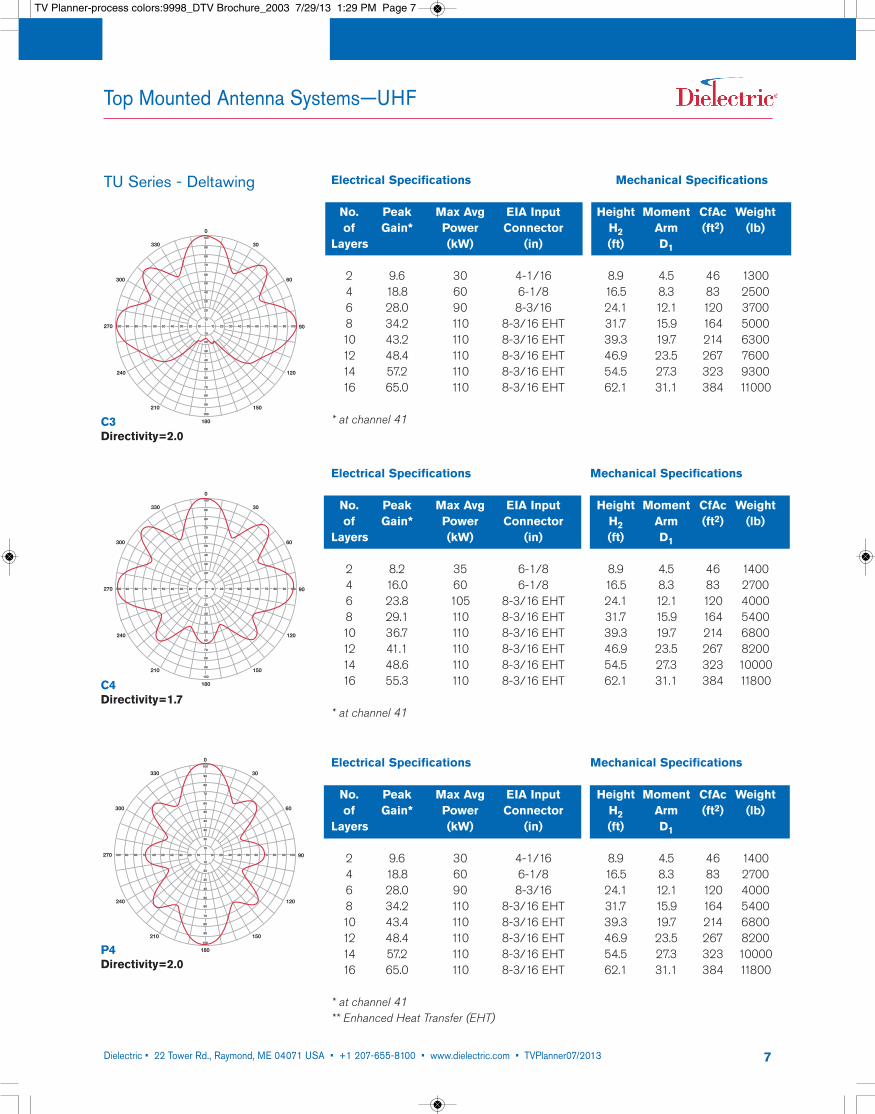
C3Directivity=2.0
330
300
270
240
210
180
150
120
90
60
30
0
20 30 40 50 60 70 80 90 100100 90 80 70 60 50 40 30 20 10 10
100
90
80
70
60
50
40
30
20
10
10
20
30
40
50
60
70
80
90
100
C4Directivity=1.7
330
300
270
240
210
180
150
120
90
60
30
0
20 30 40 50 60 70 80 90 100100 90 80 70 60 50 40 30 20 10 10
100
90
80
70
60
50
40
30
20
10
10
20
30
40
50
60
70
80
90
100
P4Directivity=2.0
TU Series - Deltawing
Electrical Specifications Mechanical Specifications
No. Peak Max Avg EIA Input Height Moment CfAc Weightof Gain* Power Connector H2 Arm (ft2) (lb)
Layers (kW) (in) (ft) D1
2 8.2 35 6-1/8 8.9 4.5 46 14004 16.0 60 6-1/8 16.5 8.3 83 27006 23.8 105 8-3/16 EHT 24.1 12.1 120 40008 29.1 110 8-3/16 EHT 31.7 15.9 164 540010 36.7 110 8-3/16 EHT 39.3 19.7 214 680012 41.1 110 8-3/16 EHT 46.9 23.5 267 820014 48.6 110 8-3/16 EHT 54.5 27.3 323 1000016 55.3 110 8-3/16 EHT 62.1 31.1 384 11800
* at channel 41
Electrical Specifications Mechanical Specifications
No. Peak Max Avg EIA Input Height Moment CfAc Weightof Gain* Power Connector H2 Arm (ft2) (lb)
Layers (kW) (in) (ft) D1
2 9.6 30 4-1/16 8.9 4.5 46 13004 18.8 60 6-1/8 16.5 8.3 83 25006 28.0 90 8-3/16 24.1 12.1 120 37008 34.2 110 8-3/16 EHT 31.7 15.9 164 500010 43.2 110 8-3/16 EHT 39.3 19.7 214 630012 48.4 110 8-3/16 EHT 46.9 23.5 267 760014 57.2 110 8-3/16 EHT 54.5 27.3 323 930016 65.0 110 8-3/16 EHT 62.1 31.1 384 11000
* at channel 41
Electrical Specifications Mechanical Specifications
No. Peak Max Avg EIA Input Height Moment CfAc Weightof Gain* Power Connector H2 Arm (ft2) (lb)
Layers (kW) (in) (ft) D1
2 9.6 30 4-1/16 8.9 4.5 46 14004 18.8 60 6-1/8 16.5 8.3 83 27006 28.0 90 8-3/16 24.1 12.1 120 40008 34.2 110 8-3/16 EHT 31.7 15.9 164 540010 43.4 110 8-3/16 EHT 39.3 19.7 214 680012 48.4 110 8-3/16 EHT 46.9 23.5 267 820014 57.2 110 8-3/16 EHT 54.5 27.3 323 1000016 65.0 110 8-3/16 EHT 62.1 31.1 384 11800
* at channel 41** Enhanced Heat Transfer (EHT)
Top Mounted Antenna Systems—UHF
TV Planner-process colors:9998_DTV Brochure_2003 7/29/13 1:29 PM Page 7
Dielectric • 22 Tower Rd., Raymond, ME 04071 USA • +1 207-655-8100 • www.dielectric.com • TVPlanner07/2013 8
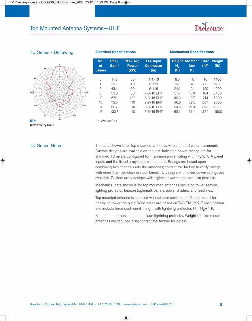
TU Series Notes The data shown is for top mounted antennas with standard panel placement.Custom designs are available on request. Indicated power ratings are for standard TU arrays configured for maximum power rating with 1-5/8” EIA panelinputs and the listed array input connections. Ratings are based upon combining two channels into the antennas; contact the factory to verify ratingswith more than two channels combined. TU designs with lower power ratings areavailable. Custom array designs with higher power ratings are also possible.
Mechanical data shown is for top mounted antennas including tower section, lighting protector, beacon (optional), panels, power dividers, and feedlines.
Top mounted antenna is supplied with adapter section and flange mount for bolting to tower top plate. Wind areas are based on TIA/EIA-222-F specificationand include force coefficient. Height with lightning protector, H4=H2+4 ft.
Side mount antennas do not include lightning protector. Weight for side mountantennas are reduced also; contact the factory for details.
TU Series - Deltawing Electrical Specifications Mechanical Specifications
No. Peak Max Avg EIA Input Height Moment CfAc Weightof Gain* Power Connector H2 Arm (ft2) (lb)
Layers (kW) (in) (ft) D1
2 14.9 20 4-1/16 8.9 4.5 46 14004 29.1 40 6-1/8 16.5 8.3 83 27006 43.4 60 6-1/8 24.1 12.1 120 40008 53.0 80 7-3/16 EHT 31.7 15.9 164 540010 67.0 100 8-3/16 EHT 39.3 19.7 214 680012 75.0 110 8-3/16 EHT 46.9 23.5 267 820014 88.7 110 8-3/16 EHT 54.5 27.3 323 1000016 100.8 110 8-3/16 EHT 62.1 31.1 384 11800
* at channel 41
Top Mounted Antenna Systems—UHF
330
300
270
240
210
180
150
120
90
60
30
0
20 30 40 50 60 70 80 90 100100 90 80 70 60 50 40 30 20 10 10
100
90
80
70
60
50
40
30
20
10
10
20
30
40
50
60
70
80
90
100
SP4Directivity=3.0
TV Planner-process colors:9998_DTV Brochure_2003 7/29/13 1:29 PM Page 8
Dielectric • 22 Tower Rd., Raymond, ME 04071 USA • +1 207-655-8100 • www.dielectric.com • TVPlanner07/2013 9
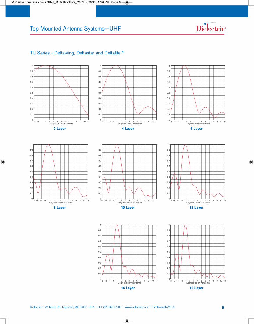
TU Series - Deltawing, Deltastar and Deltalite™
1
0.9
0.8
0.7
0.6
0.5
0.4
0.3
0.2
0.1
0-3 -2 -1 0 1 2 3 4 5 6 7 8 9 10 11
Degrees below horizontal
E
1
0.9
0.8
0.7
0.6
0.5
0.4
0.3
0.2
0.1
0-3 -2 -1 0 1 2 3 4 5 6 7 8 9 10 11
Degrees below horizontal
E
1
0.9
0.8
0.7
0.6
0.5
0.4
0.3
0.2
0.1
0-3 -2 -1 0 1 2 3 4 5 6 7 8 9 10 11
Degrees below horizontal
E
2 Layer 4 Layer 6 Layer
1
0.9
0.8
0.7
0.6
0.5
0.4
0.3
0.2
0.1
0-3 -2 -1 0 1 2 3 4 5 6 7 8 9 10 11
Degrees below horizontal
E
1
0.9
0.8
0.7
0.6
0.5
0.4
0.3
0.2
0.1
0-3 -2 -1 0 1 2 3 4 5 6 7 8 9 10 11
Degrees below horizontal
E
1
0.9
0.8
0.7
0.6
0.5
0.4
0.3
0.2
0.1
0-3 -2 -1 0 1 2 3 4 5 6 7 8 9 10 11
Degrees below horizontal
E
8 Layer 10 Layer 12 Layer
1
0.9
0.8
0.7
0.6
0.5
0.4
0.3
0.2
0.1
0-3 -2 -1 0 1 2 3 4 5 6 7 8 9 10 11
Degrees below horizontal
E
1
0.9
0.8
0.7
0.6
0.5
0.4
0.3
0.2
0.1
0-3 -2 -1 0 1 2 3 4 5 6 7 8 9 10 11
Degrees below horizontal
E
14 Layer 16 Layer
Top Mounted Antenna Systems—UHF
TV Planner-process colors:9998_DTV Brochure_2003 7/29/13 1:29 PM Page 9
Dielectric • 22 Tower Rd., Raymond, ME 04071 USA • +1 207-655-8100 • www.dielectric.com • TVPlanner07/2013 10
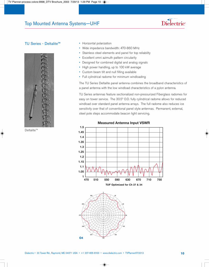
TU Series - Deltalite™
Top Mounted Antenna Systems—UHF
• Horizontal polarization• Wide impedance bandwidth: 470-860 MHz• Stainless steel elements and panel for top reliability• Excellent omni azimuth pattern circularity• Designed for combined digital and analog signals• High power handling, up to 100 kW average• Custom beam tilt and null filling available• Full cylindrical radome for minimum windloading
The TU Series Deltalite panel antenna combines the broadband characteristics ofa panel antenna with the low windload characteristics of a pylon antenna.
TU Series antennas feature sectionalized non-pressurized Fiberglass radomes foreasy on tower service. The 30.5” O.D. fully cylindrical radome allows for reducedwindload over standard panel antenna arrays. The full radome also reduces icesensitivity over that of conventional panel style antennas. Permanent, external,steel pole steps accommodate beacon light servicing.
DeltaliteTM
TUF Optimized for Ch 27 & 34
1.5
1.45
1.4
1.35
1.3
1.25
1.2
1.15
1.1
1.05
1470 510 550 590 630 670 710 750
Measured Antenna Input VSWR
330
300
270
240
210
180
150
120
90
60
30
0
20 30 40 50 60 70 80 90 100100 90 80 70 60 50 40 30 20 10 10
100
90
80
70
60
50
40
30
20
10
10
20
30
40
50
60
70
80
90
100
O4
TV Planner-process colors:9998_DTV Brochure_2003 7/29/13 1:29 PM Page 10
Dielectric • 22 Tower Rd., Raymond, ME 04071 USA • +1 207-655-8100 • www.dielectric.com • TVPlanner07/2013 11
Top Mounted Antenna Systems—UHF
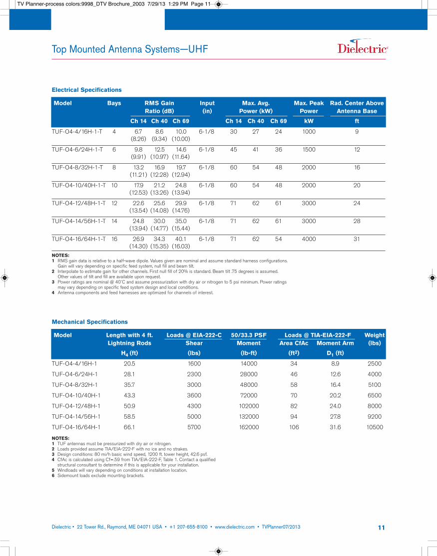
Electrical Specifications
Model Bays RMS Gain Input Max. Avg. Max. Peak Rad. Center AboveRatio (dB) (in) Power (kW) Power Antenna Base
Ch 14 Ch 40 Ch 69 Ch 14 Ch 40 Ch 69 kW ft
TUF-O4-4/16H-1-T 4 6.7 8.6 10.0 6-1/8 30 27 24 1000 9(8.26) (9.34) (10.00)
TUF-O4-6/24H-1-T 6 9.8 12.5 14.6 6-1/8 45 41 36 1500 12(9.91) (10.97) (11.64)
TUF-O4-8/32H-1-T 8 13.2 16.9 19.7 6-1/8 60 54 48 2000 16(11.21) (12.28) (12.94)
TUF-O4-10/40H-1-T 10 17.9 21.2 24.8 6-1/8 60 54 48 2000 20(12.53) (13.26) (13.94)
TUF-O4-12/48H-1-T 12 22.6 25.6 29.9 6-1/8 71 62 61 3000 24(13.54) (14.08) (14.76)
TUF-O4-14/56H-1-T 14 24.8 30.0 35.0 6-1/8 71 62 61 3000 28(13.94) (14.77) (15.44)
TUF-O4-16/64H-1-T 16 26.9 34.3 40.1 6-1/8 71 62 54 4000 31(14.30) (15.35) (16.03)
NOTES:1 RMS gain data is relative to a half-wave dipole. Values given are nominal and assume standard harness configurations.
Gain will vary depending on specific feed system, null fill and beam tilt.2 Interpolate to estimate gain for other channels. First null fill of 20% is standard. Beam tilt .75 degrees is assumed.
Other values of tilt and fill are available upon request.3 Power ratings are nominal @ 40˚C and assume pressurization with dry air or nitrogen to 5 psi minimum. Power ratings
may vary depending on specific feed system design and local conditions.4 Antenna components and feed harnesses are optimized for channels of interest.
Mechanical Specifications
Model Length with 4 ft. Loads @ EIA-222-C 50/33.3 PSF Loads @ TIA-EIA-222-F WeightLightning Rods Shear Moment Area CfAc Moment Arm (lbs)
H4 (ft) (lbs) (lb-ft) (ft2) D1 (ft)
TUF-O4-4/16H-1 20.5 1600 14000 34 8.9 2500
TUF-O4-6/24H-1 28.1 2300 28000 46 12.6 4000
TUF-O4-8/32H-1 35.7 3000 48000 58 16.4 5100
TUF-O4-10/40H-1 43.3 3600 72000 70 20.2 6500
TUF-O4-12/48H-1 50.9 4300 102000 82 24.0 8000
TUF-O4-14/56H-1 58.5 5000 132000 94 27.8 9200
TUF-O4-16/64H-1 66.1 5700 162000 106 31.6 10500
NOTES:1 TUF antennas must be pressurized with dry air or nitrogen.2 Loads provided assume TIA/EIA-222-F with no ice and no strakes. 3 Design conditions: 80 mi/h basic wind speed, 1200 ft. tower height, 42.6 psf.4 CfAc is calculated using Cf=.59 from TIA/EIA-222-F, Table 1. Contact a qualified
structural consultant to determine if this is applicable for your installation.5 Windloads will vary depending on conditions at installation location.6 Sidemount loads exclude mounting brackets.
TV Planner-process colors:9998_DTV Brochure_2003 7/29/13 1:29 PM Page 11
Dielectric • 22 Tower Rd., Raymond, ME 04071 USA • +1 207-655-8100 • www.dielectric.com • TVPlanner07/2013 12
Top Mounted Antenna Systems—UHF
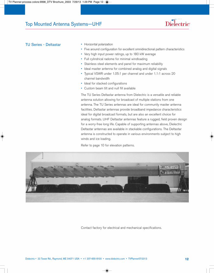
TU Series - Deltastar • Horizontal polarization• Five around configuration for excellent omnidirectional pattern characteristics• Very high input power ratings, up to 180 kW average• Full cylindrical radome for minimal windloading• Stainless steel elements and panel for maximum reliability• Ideal master antenna for combined analog and digital signals• Typical VSWR under 1.05:1 per channel and under 1.1:1 across 20 channel bandwidth
• Ideal for stacked configurations• Custom beam tilt and null fill available
The TU Series Deltastar antenna from Dielectric is a versatile and reliableantenna solution allowing for broadcast of multiple stations from one antenna. The TU Series antennas are ideal for community master antennafacilities. Deltastar antennas provide broadband impedance characteristicsideal for digital broadcast formats, but are also an excellent choice for analog formats. UHF Deltastar antennas feature a rugged, field proven designfor a worry-free long life. Capable of supporting antennas above, DielectricDeltastar antennas are available in stackable configurations. The Deltastarantenna is constructed to operate in various environments subject to highwinds and ice loading.
Refer to page 10 for elevation patterns.
Contact factory for electrical and mechanical specifications.
TV Planner-process colors:9998_DTV Brochure_2003 7/29/13 1:29 PM Page 12
Dielectric • 22 Tower Rd., Raymond, ME 04071 USA • +1 207-655-8100 • www.dielectric.com • TVPlanner07/2013 13
Top Mounted Antenna Systems—UHF
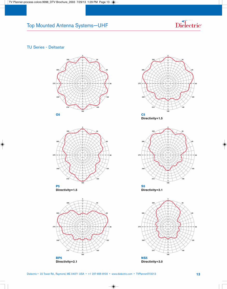
TU Series - Deltastar
330
300
270
240
210
180
150
120
90
60
30
0
20 30 40 50 60 70 80 90 100100 90 80 70 60 50 40 30 20 10 10
100
90
80
70
60
50
40
30
20
10
10
20
30
40
50
60
70
80
90
100
O5
330
300
270
240
210
180
150
120
90
60
30
0
20 30 40 50 60 70 80 90 100100 90 80 70 60 50 40 30 20 10 10
100
90
80
70
60
50
40
30
20
10
10
20
30
40
50
60
70
80
90
100
P5Directivity=1.5
330
300
270
240
210
180
150
120
90
60
30
0
20 30 40 50 60 70 80 90 100100 90 80 70 60 50 40 30 20 10 10
100
90
80
70
60
50
40
30
20
10
10
20
30
40
50
60
70
80
90
100
BP5Directivity=2.1
330
300
270
240
210
180
150
120
90
60
30
0
20 30 40 50 60 70 80 90 100100 90 80 70 60 50 40 30 20 10 10
100
90
80
70
60
50
40
30
20
10
10
20
30
40
50
60
70
80
90
100
C5Directivity=1.5
330
300
270
240
210
180
150
120
90
60
30
0
20 30 40 50 60 70 80 90 100100 90 80 70 60 50 40 30 20 10 10
100
90
80
70
60
50
40
30
20
10
10
20
30
40
50
60
70
80
90
100
S5Directivity=2.1
330
300
270
240
210
180
150
120
90
60
30
0
20 30 40 50 60 70 80 90 100100 90 80 70 60 50 40 30 20 10 10
100
90
80
70
60
50
40
30
20
10
10
20
30
40
50
60
70
80
90
100
NS5Directivity=3.0
TV Planner-process colors:9998_DTV Brochure_2003 7/29/13 1:29 PM Page 13

Dielectric • 22 Tower Rd., Raymond, ME 04071 USA • +1 207-655-8100 • www.dielectric.com • TVPlanner07/2013 14
Top Mounted Antenna Systems—VHF
Suited for those stations allocated VHF DTV Channels, Dielectric’s product lineincludes a wide array of VHF antenna products. Dielectric has a wide variety oftop mounted and side mounted antenna models to choose from in both horizontal and circular polarization. The TW and THV Series pylon antennas,TUV Series dualband arrays, TH Series panel arrays, TF Series superturnstilearrays and the new TLS-V low power VHF arrays are discussed in more detailthroughout this catalog. For circularly polarized applications contact factory.
VHF
• Excellent circularity
• Proven pylon design with low windload
• Can be structurally designed for stacking
• Full polycarbonate radome standard*
• High power handling
• Ideal for NTSC or DTV transmission
• Elevation gains from 7 (8.45dB) to 15 (11.76dB)
This horizontally polarized traveling wave antenna for Channels 7 to 13 uses the reliable technology Dielectric is known for in a very aperture efficient, lowwindload design. The TW antenna is designed for omnidirectional applications.
This antenna comes with a full radome. The strong polycarbonate radome isimpregnated with international orange or white and does not require any paintingduring its lifetime. Non-radomed versions are available upon request. Bothradomed or non-radomed versions can be ordered with pressurized pole. Sinceonly the pole is pressurized and not the radome, the antenna is easily accessiblefor inspection. Pole pressurization is not required for normal operation of theantenna.
Other available options are bury mount and side mounting on a tower.
TW Series
*Slot covers and deicers optional.
TV Planner-process colors:9998_DTV Brochure_2003 7/29/13 1:29 PM Page 14
Dielectric • 22 Tower Rd., Raymond, ME 04071 USA • +1 207-655-8100 • www.dielectric.com • TVPlanner07/2013 15
Top Mounted Antenna Systems—VHF
1
0.9
0.8
0.7
0.6
0.5
0.4
0.3
0.2
0.1
0-3 -2 -1 0 1 2 3 4 5 6 7 8 9 10 11
Degrees below horizontal
E
1
0.9
0.8
0.7
0.6
0.5
0.4
0.3
0.2
0.1
0-3 -2 -1 0 1 2 3 4 5 6 7 8 9 10 11
Degrees below horizontal
E
1
0.9
0.8
0.7
0.6
0.5
0.4
0.3
0.2
0.1
0-3 -2 -1 0 1 2 3 4 5 6 7 8 9 10 11
Degrees below horizontal
E
1
0.9
0.8
0.7
0.6
0.5
0.4
0.3
0.2
0.1
0-3 -2 -1 0 1 2 3 4 5 6 7 8 9 10 11
Degrees below horizontal
E
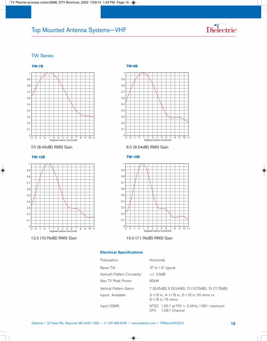
TW-7B TW-9B
TW-12B TW-15B
TW Series
Electrical Specifications
Polarization: Horizontal
Beam Tilt: .5° to 1.0˚ typical
Azimuth Pattern Circularity: +/- 0.8dB
Max TV Peak Power: 80kW
Vertical Pattern Gains: 7 (8.45dB), 9 (9.54dB), 12 (10.79dB), 15 (11.76dB)
Inputs Available: 3-1/8 in., 4-1/16 in., 6-1/8 in. 50 ohms or 6-1/8 in. 75 ohms
Input VSWR: NTSC 1.05:1 at PIX + .5 MHz, 1.08:1 maximum DTV 1.08:1 Channel
7.0 (8.45dB) RMS Gain 9.0 (9.54dB) RMS Gain
12.0 (10.79dB) RMS Gain 15.0 (11.76dB) RMS Gain
TV Planner-process colors:9998_DTV Brochure_2003 7/29/13 1:29 PM Page 15
Dielectric • 22 Tower Rd., Raymond, ME 04071 USA • +1 207-655-8100 • www.dielectric.com • TVPlanner07/2013 16
Top Mounted Antenna Systems—VHF
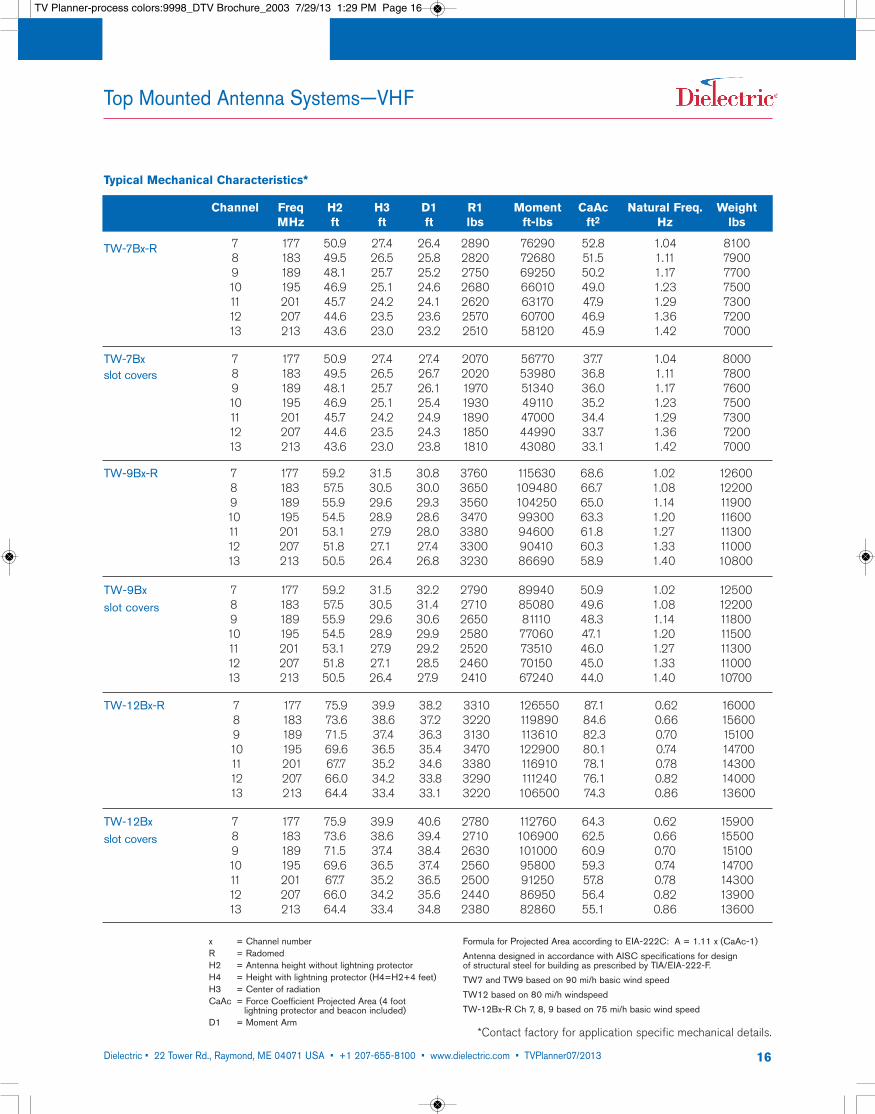
Channel Freq H2 H3 D1 R1 Moment CaAc Natural Freq. WeightMHz ft ft ft lbs ft-lbs ft2 Hz lbs
7 177 50.9 27.4 26.4 2890 76290 52.8 1.04 81008 183 49.5 26.5 25.8 2820 72680 51.5 1.11 79009 189 48.1 25.7 25.2 2750 69250 50.2 1.17 770010 195 46.9 25.1 24.6 2680 66010 49.0 1.23 750011 201 45.7 24.2 24.1 2620 63170 47.9 1.29 730012 207 44.6 23.5 23.6 2570 60700 46.9 1.36 720013 213 43.6 23.0 23.2 2510 58120 45.9 1.42 7000
TW-7Bx-R
TW-7Bx slot covers
7 177 50.9 27.4 27.4 2070 56770 37.7 1.04 80008 183 49.5 26.5 26.7 2020 53980 36.8 1.11 78009 189 48.1 25.7 26.1 1970 51340 36.0 1.17 760010 195 46.9 25.1 25.4 1930 49110 35.2 1.23 750011 201 45.7 24.2 24.9 1890 47000 34.4 1.29 730012 207 44.6 23.5 24.3 1850 44990 33.7 1.36 720013 213 43.6 23.0 23.8 1810 43080 33.1 1.42 7000
7 177 59.2 31.5 30.8 3760 115630 68.6 1.02 126008 183 57.5 30.5 30.0 3650 109480 66.7 1.08 122009 189 55.9 29.6 29.3 3560 104250 65.0 1.14 1190010 195 54.5 28.9 28.6 3470 99300 63.3 1.20 1160011 201 53.1 27.9 28.0 3380 94600 61.8 1.27 1130012 207 51.8 27.1 27.4 3300 90410 60.3 1.33 1100013 213 50.5 26.4 26.8 3230 86690 58.9 1.40 10800
7 177 59.2 31.5 32.2 2790 89940 50.9 1.02 125008 183 57.5 30.5 31.4 2710 85080 49.6 1.08 122009 189 55.9 29.6 30.6 2650 81110 48.3 1.14 1180010 195 54.5 28.9 29.9 2580 77060 47.1 1.20 1150011 201 53.1 27.9 29.2 2520 73510 46.0 1.27 1130012 207 51.8 27.1 28.5 2460 70150 45.0 1.33 1100013 213 50.5 26.4 27.9 2410 67240 44.0 1.40 10700
7 177 75.9 39.9 38.2 3310 126550 87.1 0.62 160008 183 73.6 38.6 37.2 3220 119890 84.6 0.66 156009 189 71.5 37.4 36.3 3130 113610 82.3 0.70 1510010 195 69.6 36.5 35.4 3470 122900 80.1 0.74 1470011 201 67.7 35.2 34.6 3380 116910 78.1 0.78 1430012 207 66.0 34.2 33.8 3290 111240 76.1 0.82 1400013 213 64.4 33.4 33.1 3220 106500 74.3 0.86 13600
TW-9Bx-R
TW-9Bx slot covers
TW-12Bx-R
TW-12Bxslot covers
7 177 75.9 39.9 40.6 2780 112760 64.3 0.62 159008 183 73.6 38.6 39.4 2710 106900 62.5 0.66 155009 189 71.5 37.4 38.4 2630 101000 60.9 0.70 1510010 195 69.6 36.5 37.4 2560 95800 59.3 0.74 1470011 201 67.7 35.2 36.5 2500 91250 57.8 0.78 1430012 207 66.0 34.2 35.6 2440 86950 56.4 0.82 1390013 213 64.4 33.4 34.8 2380 82860 55.1 0.86 13600
x = Channel numberR = RadomedH2 = Antenna height without lightning protectorH4 = Height with lightning protector (H4=H2+4 feet)H3 = Center of radiationCaAc = Force Coefficient Projected Area (4 foot
lightning protector and beacon included)D1 = Moment Arm
Formula for Projected Area according to EIA-222C: A = 1.11 x (CaAc-1)Antenna designed in accordance with AISC specifications for design of structural steel for building as prescribed by TIA/EIA-222-F.TW7 and TW9 based on 90 mi/h basic wind speedTW12 based on 80 mi/h windspeedTW-12Bx-R Ch 7, 8, 9 based on 75 mi/h basic wind speed
*Contact factory for application specific mechanical details.
Typical Mechanical Characteristics*
TV Planner-process colors:9998_DTV Brochure_2003 7/29/13 1:29 PM Page 16
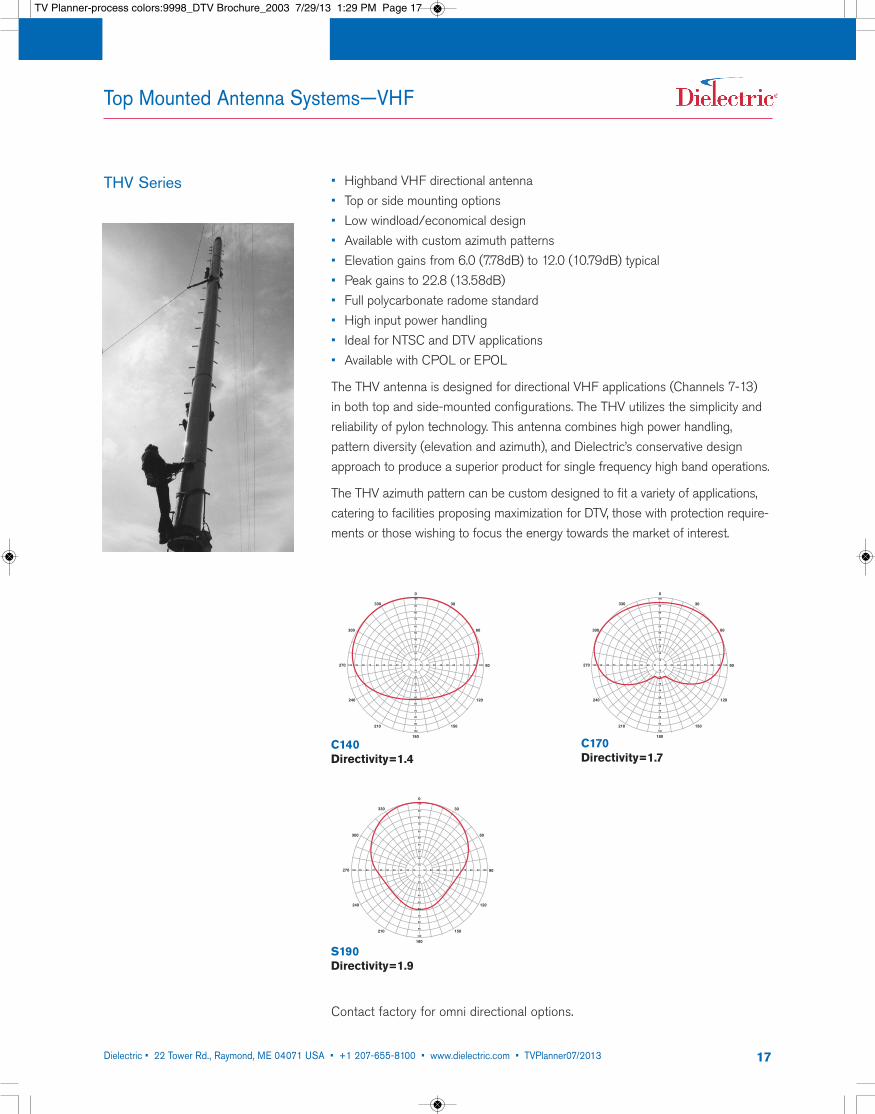
• Highband VHF directional antenna• Top or side mounting options• Low windload/economical design• Available with custom azimuth patterns• Elevation gains from 6.0 (7.78dB) to 12.0 (10.79dB) typical• Peak gains to 22.8 (13.58dB)• Full polycarbonate radome standard• High input power handling• Ideal for NTSC and DTV applications• Available with CPOL or EPOL
The THV antenna is designed for directional VHF applications (Channels 7-13) in both top and side-mounted configurations. The THV utilizes the simplicity andreliability of pylon technology. This antenna combines high power handling, pattern diversity (elevation and azimuth), and Dielectric’s conservative designapproach to produce a superior product for single frequency high band operations.
The THV azimuth pattern can be custom designed to fit a variety of applications,catering to facilities proposing maximization for DTV, those with protection require-ments or those wishing to focus the energy towards the market of interest.
Dielectric • 22 Tower Rd., Raymond, ME 04071 USA • +1 207-655-8100 • www.dielectric.com • TVPlanner07/2013 17
Top Mounted Antenna Systems—VHF
THV Series
330
300
270
240
210
180
150
120
90
60
30
0
20 30 40 50 60 70 80 90 100100 90 80 70 60 50 40 30 20 10 10
100
90
80
70
60
50
40
30
20
10
10
20
30
40
50
60
70
80
90
100
330
300
270
240
210
180
150
120
90
60
30
0
20 30 40 50 60 70 80 90 100100 90 80 70 60 50 40 30 20 10 10
100
90
80
70
60
50
40
30
20
10
10
20
30
40
50
60
70
80
90
100
330
300
270
240
210
180
150
120
90
60
30
0
20 30 40 50 60 70 80 90 100100 90 80 70 60 50 40 30 20 10 10
100
90
80
70
60
50
40
30
20
10
10
20
30
40
50
60
70
80
90
100
C140Directivity=1.4
C170Directivity=1.7
S190Directivity=1.9
Contact factory for omni directional options.
TV Planner-process colors:9998_DTV Brochure_2003 7/29/13 1:29 PM Page 17
Dielectric • 22 Tower Rd., Raymond, ME 04071 USA • +1 207-655-8100 • www.dielectric.com • TVPlanner07/2013 18
Top Mounted Antenna Systems—VHF
THV Series
1
0.9
0.8
0.7
0.6
0.5
0.4
0.3
0.2
0.1
0-3 -2 -1 0 1 2 3 4 5 6 7 8 9 10 11
Degrees below horizontal
E
1
0.9
0.8
0.7
0.6
0.5
0.4
0.3
0.2
0.1
0-3 -2 -1 0 1 2 3 4 5 6 7 8 9 10 11
Degrees below horizontal
E
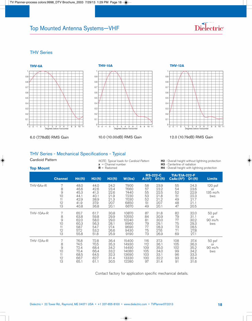
THV-6A THV-10A
1
0.9
0.8
0.7
0.6
0.5
0.4
0.3
0.2
0.1
0-3 -2 -1 0 1 2 3 4 5 6 7 8 9 10 11
Degrees below horizontal
E
THV-12A
THV Series - Mechanical Specifications - TypicalCardioid Pattern
Top Mount
RS-222-C TIA/EIA-222-FChannel H4(ft) H2(ft) H3(ft) W(lbs) A(ft2) D1(ft) CaAc(ft2) D1(ft) Limits
THV-6Ax-R 7 48.0 44.0 24.2 7900 58 23.9 55 24.3 120 psf8 46.6 42.6 23.4 7660 57 23.2 54 23.6 or9 45.3 41.3 22.6 7440 55 22.5 52 22.9 135 mi/h10 44.1 40.1 21.9 7230 53 21.8 51 22.3 bws11 42.9 38.9 21.3 7030 52 21.2 49 21.712 41.9 37.9 20.7 6850 51 20.7 48 21.113 40.8 36.8 20.1 6670 49 20.1 47 20.5
THV-10Ax-R 7 65.7 61.7 30.8 10870 87 31.8 82 32.0 50 psf8 63.8 59.8 29.9 10550 84 30.9 79 31.1 or9 62.0 58.0 29.0 10240 81 30.0 77 30.2 90 mi/h10 60.3 56.3 28.1 9960 79 29.1 75 29.3 bws11 58.7 54.7 27.4 9690 77 28.3 73 28.512 57.2 53.2 26.6 9430 75 27.6 71 27.813 55.8 51.8 25.9 9190 73 26.9 69 27.1
THV-12Ax-R 7 76.8 72.8 36.4 15400 116 37.3 108 37.4 50 psf8 74.5 70.5 35.3 14930 112 36.1 105 36.3 or9 72.4 68.4 34.2 14490 109 35.0 102 35.2 90 mi/h10 70.4 66.4 33.2 14080 105 34.0 99 34.2 bws11 68.5 64.5 32.3 13690 103 33.1 96 33.312 66.7 62.7 31.4 13330 100 32.2 93 32.413 65.1 61.1 30.5 12280 97 31.4 91 31.6
NOTE: Typical loads for Cardioid Patternx = Channel numberR = Radomed
H2 - Overall height without lightning protectionH3 - Centerline of radiationH4 - Overall height with lightning protection
Contact factory for application specific mechanical details.
6.0 (7.78dB) RMS Gain 10.0 (10.00dB) RMS Gain 12.0 (10.79dB) RMS Gain
TV Planner-process colors:9998_DTV Brochure_2003 7/29/13 1:29 PM Page 18
Dielectric • 22 Tower Rd., Raymond, ME 04071 USA • +1 207-655-8100 • www.dielectric.com • TVPlanner07/2013 19
Top Mounted Antenna Systems—VHF
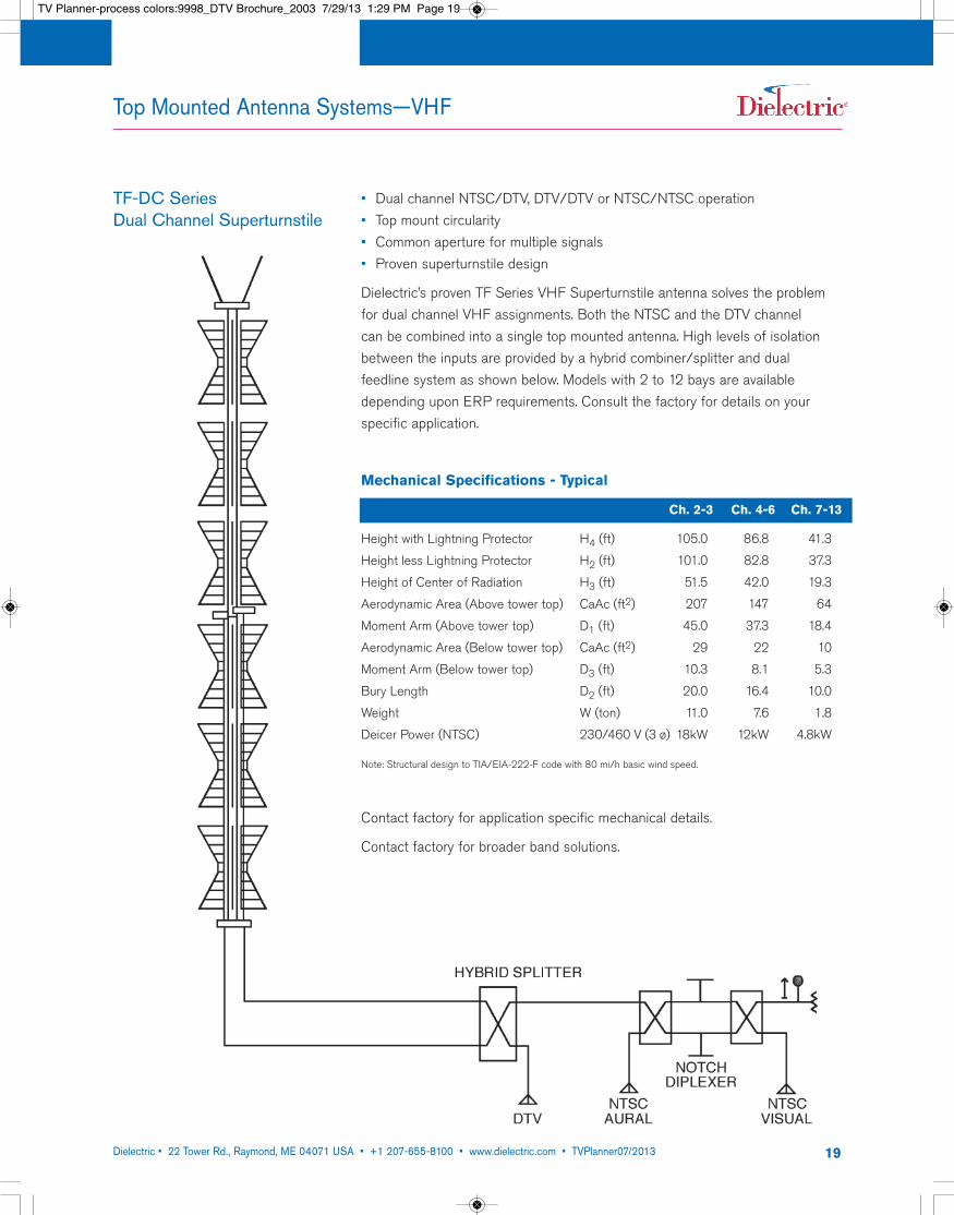
• Dual channel NTSC/DTV, DTV/DTV or NTSC/NTSC operation• Top mount circularity • Common aperture for multiple signals• Proven superturnstile design
Dielectric’s proven TF Series VHF Superturnstile antenna solves the problemfor dual channel VHF assignments. Both the NTSC and the DTV channel can be combined into a single top mounted antenna. High levels of isolationbetween the inputs are provided by a hybrid combiner/splitter and dual feedline system as shown below. Models with 2 to 12 bays are availabledepending upon ERP requirements. Consult the factory for details on your specific application.
TF-DC Series Dual Channel Superturnstile
Mechanical Specifications - Typical
Ch. 2-3 Ch. 4-6 Ch. 7-13
Height with Lightning Protector H4 (ft) 105.0 86.8 41.3
Height less Lightning Protector H2 (ft) 101.0 82.8 37.3
Height of Center of Radiation H3 (ft) 51.5 42.0 19.3
Aerodynamic Area (Above tower top) CaAc (ft2) 207 147 64
Moment Arm (Above tower top) D1 (ft) 45.0 37.3 18.4
Aerodynamic Area (Below tower top) CaAc (ft2) 29 22 10
Moment Arm (Below tower top) D3 (ft) 10.3 8.1 5.3
Bury Length D2 (ft) 20.0 16.4 10.0
Weight W (ton) 11.0 7.6 1.8
Deicer Power (NTSC) 230/460 V (3 ø) 18kW 12kW 4.8kW
Note: Structural design to TIA/EIA-222-F code with 80 mi/h basic wind speed.
Contact factory for application specific mechanical details.
Contact factory for broader band solutions.
TV Planner-process colors:9998_DTV Brochure_2003 7/29/13 1:29 PM Page 19
Dielectric • 22 Tower Rd., Raymond, ME 04071 USA • +1 207-655-8100 • www.dielectric.com • TVPlanner07/2013 20
Top Mounted Antenna Systems—UHF&VHF Common Aperture Arrays
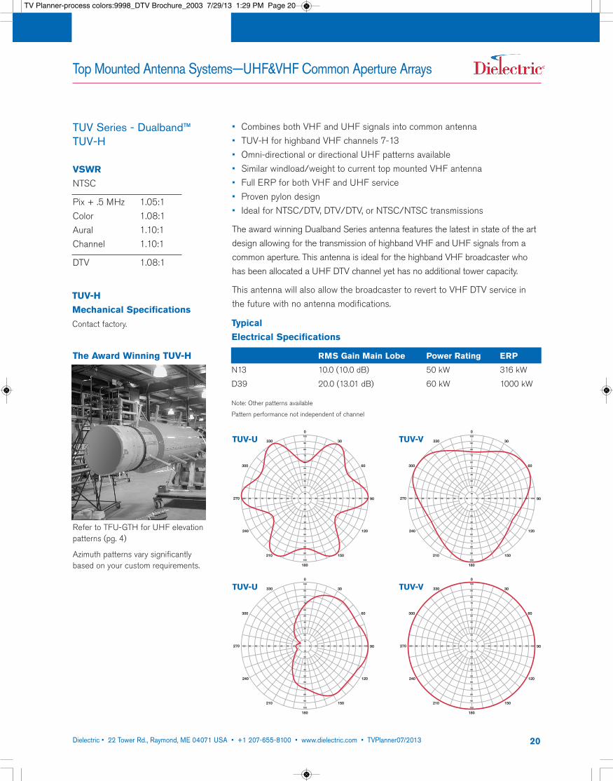
TUV Series - Dualband™TUV-H
330
300
270
240
210
180
150
120
90
60
30
0
20 30 40 50 60 70 80 90 100100 90 80 70 60 50 40 30 20 10 10
100
90
80
70
60
50
40
30
20
10
10
20
30
40
50
60
70
80
90
100
TUV-U 330
300
270
240
210
180
150
120
90
60
30
0
20 30 40 50 60 70 80 90 100100 90 80 70 60 50 40 30 20 10 10
100
90
80
70
60
50
40
30
20
10
10
20
30
40
50
60
70
80
90
100
TUV-V
• Combines both VHF and UHF signals into common antenna• TUV-H for highband VHF channels 7-13• Omni-directional or directional UHF patterns available• Similar windload/weight to current top mounted VHF antenna• Full ERP for both VHF and UHF service• Proven pylon design• Ideal for NTSC/DTV, DTV/DTV, or NTSC/NTSC transmissions
The award winning Dualband Series antenna features the latest in state of the artdesign allowing for the transmission of highband VHF and UHF signals from acommon aperture. This antenna is ideal for the highband VHF broadcaster whohas been allocated a UHF DTV channel yet has no additional tower capacity.
This antenna will also allow the broadcaster to revert to VHF DTV service inthe future with no antenna modifications.
Refer to TFU-GTH for UHF elevationpatterns (pg. 4)
Azimuth patterns vary significantlybased on your custom requirements.
VSWRNTSC
Pix + .5 MHz 1.05:1Color 1.08:1Aural 1.10:1Channel 1.10:1
DTV 1.08:1
330
300
270
240
210
180
150
120
90
60
30
0
20 30 40 50 60 70 80 90 100100 90 80 70 60 50 40 30 20 10 10
100
90
80
70
60
50
40
30
20
10
10
20
30
40
50
60
70
80
90
100
TUV-U 330
300
270
240
210
180
150
120
90
60
30
0
20 30 40 50 60 70 80 90 100100 90 80 70 60 50 40 30 20 10 10
100
90
80
70
60
50
40
30
20
10
10
20
30
40
50
60
70
80
90
100
TUV-V
TUV-HMechanical SpecificationsContact factory. Typical
Electrical Specifications
RMS Gain Main Lobe Power Rating ERP
N13 10.0 (10.0 dB) 50 kW 316 kW
D39 20.0 (13.01 dB) 60 kW 1000 kW
Note: Other patterns available
Pattern performance not independent of channel
The Award Winning TUV-H
TV Planner-process colors:9998_DTV Brochure_2003 7/29/13 1:29 PM Page 20
Dielectric • 22 Tower Rd., Raymond, ME 04071 USA • +1 207-655-8100 • www.dielectric.com • TVPlanner07/2013 21
Top Mounted Antenna Systems—UHF&VHF Common Aperture Arrays
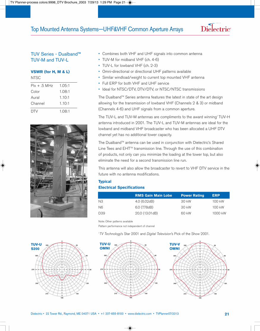
TUV Series - Dualband™TUV-M and TUV-L
330
300
270
240
210
180
150
120
90
60
30
0
20 30 40 50 60 70 80 90 100100 90 80 70 60 50 40 30 20 10 10
100
90
80
70
60
50
40
30
20
10
10
20
30
40
50
60
70
80
90
100
TUV-US200
330
300
270
240
210
180
150
120
90
60
30
0
20 30 40 50 60 70 80 90 100100 90 80 70 60 50 40 30 20 10 10
100
90
80
70
60
50
40
30
20
10
10
20
30
40
50
60
70
80
90
100
TUV-VOMNI
• Combines both VHF and UHF signals into common antenna• TUV-M for midband VHF (ch. 4-6)• TUV-L for lowband VHF (ch. 2-3)• Omni-directional or directional UHF patterns available• Similar windload/weight to current top mounted VHF antenna• Full ERP for both VHF and UHF service• Ideal for NTSC/DTV, DTV/DTV, or NTSC/NTSC transmissions
The DualbandTM Series antenna features the latest in state of the art designallowing for the transmission of lowband VHF (Channels 2 & 3) or midband(Channels 4-6) and UHF signals from a common aperture.
The TUV-L and TUV-M antennas are compliments to the award winning1 TUV-Hantenna introduced in 2001. The TUV-L and TUV-M antennas are ideal for thelowband and midband VHF broadcaster who has been allocated a UHF DTVchannel yet has no additional tower capacity.
The DualbandTM antenna can be used in conjunction with Dielectric’s Shared Line Tees and EHTTM transmission line. Through the use of this combination of products, not only can you minimize the loading at the tower top, but also eliminate the need for a second transmission line run.
This antenna will also allow the broadcaster to revert to VHF DTV service in thefuture with no antenna modifications.
Typical Electrical Specifications
RMS Gain Main Lobe Power Rating ERP
N3 4.0 (6.02dB) 30 kW 100 kW
N6 6.0 (7.78dB) 30 kW 100 kW
D39 20.0 (13.01dB) 60 kW 1000 kW
Note: Other patterns available
Pattern performance not independent of channel
VSWR (for H, M & L)NTSC
Pix + .5 MHz 1.05:1Color 1.08:1Aural 1.10:1Channel 1.10:1
DTV 1.08:1
330
300
270
240
210
180
150
120
90
60
30
0
20 30 40 50 60 70 80 90 100100 90 80 70 60 50 40 30 20 10 10
100
90
80
70
60
50
40
30
20
10
10
20
30
40
50
60
70
80
90
100
TUV-UOMNI
1TV Technology’s Star 2001 and Digital Television’s Pick of the Show 2001.
TV Planner-process colors:9998_DTV Brochure_2003 7/29/13 1:29 PM Page 21
Dielectric • 22 Tower Rd., Raymond, ME 04071 USA • +1 207-655-8100 • www.dielectric.com • TVPlanner07/2013 22
Top Mounted Antenna Systems—UHF&VHF Common Aperture Arrays
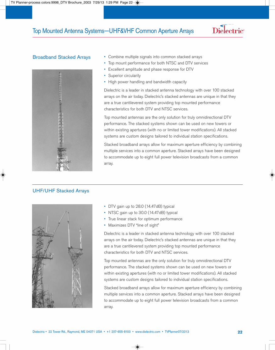
• Combine multiple signals into common stacked arrays• Top mount performance for both NTSC and DTV services• Excellent amplitude and phase response for DTV• Superior circularity• High power handling and bandwidth capacity
Dielectric is a leader in stacked antenna technology with over 100 stackedarrays on the air today. Dielectric’s stacked antennas are unique in that theyare a true cantilevered system providing top mounted performance characteristics for both DTV and NTSC services.
Top mounted antennas are the only solution for truly omnidirectional DTV performance. The stacked systems shown can be used on new towers or within existing apertures (with no or limited tower modifications). All stackedsystems are custom designs tailored to individual station specifications.
Stacked broadband arrays allow for maximum aperture efficiency by combiningmultiple services into a common aperture. Stacked arrays have been designedto accommodate up to eight full power television broadcasts from a commonarray.
UHF/UHF Stacked Arrays
• DTV gain up to 28.0 (14.47dB) typical• NTSC gain up to 30.0 (14.47dB) typical• True linear stack for optimum performance• Maximizes DTV “line of sight”
Dielectric is a leader in stacked antenna technology with over 100 stackedarrays on the air today. Dielectric’s stacked antennas are unique in that theyare a true cantilevered system providing top mounted performance characteristics for both DTV and NTSC services.
Top mounted antennas are the only solution for truly omnidirectional DTV performance. The stacked systems shown can be used on new towers or within existing apertures (with no or limited tower modifications). All stackedsystems are custom designs tailored to individual station specifications.
Stacked broadband arrays allow for maximum aperture efficiency by combiningmultiple services into a common aperture. Stacked arrays have been designedto accommodate up to eight full power television broadcasts from a commonarray.
Broadband Stacked Arrays
TV Planner-process colors:9998_DTV Brochure_2003 7/29/13 1:29 PM Page 22
Dielectric • 22 Tower Rd., Raymond, ME 04071 USA • +1 207-655-8100 • www.dielectric.com • TVPlanner07/2013 23
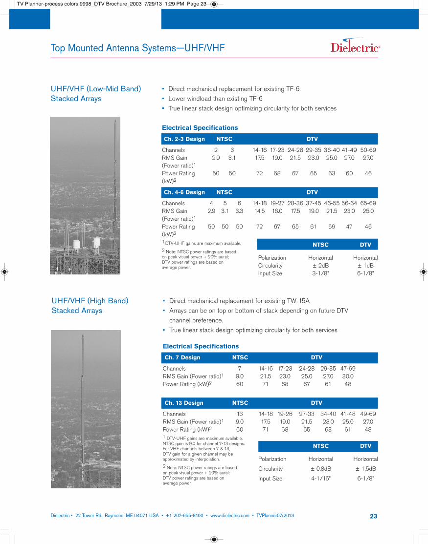
UHF/VHF (Low-Mid Band)Stacked Arrays
• Direct mechanical replacement for existing TF-6• Lower windload than existing TF-6• True linear stack design optimizing circularity for both services
Electrical Specifications
Ch. 2-3 Design NTSC DTV
Channels 2 3 14-16 17-23 24-28 29-35 36-40 41-49 50-69RMS Gain 2.9 3.1 17.5 19.0 21.5 23.0 25.0 27.0 27.0(Power ratio)1Power Rating 50 50 72 68 67 65 63 60 46(kW)2
Ch. 4-6 Design NTSC DTV
Channels 4 5 6 14-18 19-27 28-36 37-45 46-55 56-64 65-69RMS Gain 2.9 3.1 3.3 14.5 16.0 17.5 19.0 21.5 23.0 25.0(Power ratio)1Power Rating 50 50 50 72 67 65 61 59 47 46(kW)21DTV-UHF gains are maximum available.2 Note: NTSC power ratings are based on peak visual power + 20% aural; DTV power ratings are based on average power.
NTSC DTV
Polarization Horizontal HorizontalCircularity ± 2dB ± 1dBInput Size 3-1/8” 6-1/8”
Top Mounted Antenna Systems—UHF/VHF
• Direct mechanical replacement for existing TW-15A• Arrays can be on top or bottom of stack depending on future DTV channel preference.
• True linear stack design optimizing circularity for both services
Electrical Specifications
Ch. 7 Design NTSC DTV
Channels 7 14-16 17-23 24-28 29-35 47-69RMS Gain (Power ratio)1 9.0 21.5 23.0 25.0 27.0 30.0Power Rating (kW)2 60 71 68 67 61 48
Ch. 13 Design NTSC DTV
Channels 13 14-18 19-26 27-33 34-40 41-48 49-69RMS Gain (Power ratio)1 9.0 17.5 19.0 21.5 23.0 25.0 27.0Power Rating (kW)2 60 71 68 65 63 61 481 DTV-UHF gains are maximum available. NTSC gain is 9.0 for channel 7-13 designs. For VHF channels between 7 & 13, DTV gain for a given channel may be approximated by interpolation.2 Note: NTSC power ratings are based on peak visual power + 20% aural; DTV power ratings are based on average power.
NTSC DTV
Polarization Horizontal Horizontal
Circularity ± 0.8dB ± 1.5dB
Input Size 4-1/16” 6-1/8”
UHF/VHF (High Band)Stacked Arrays
TV Planner-process colors:9998_DTV Brochure_2003 7/29/13 1:29 PM Page 23
Dielectric • 22 Tower Rd., Raymond, ME 04071 USA • +1 207-655-8100 • www.dielectric.com • TVPlanner07/2013 24
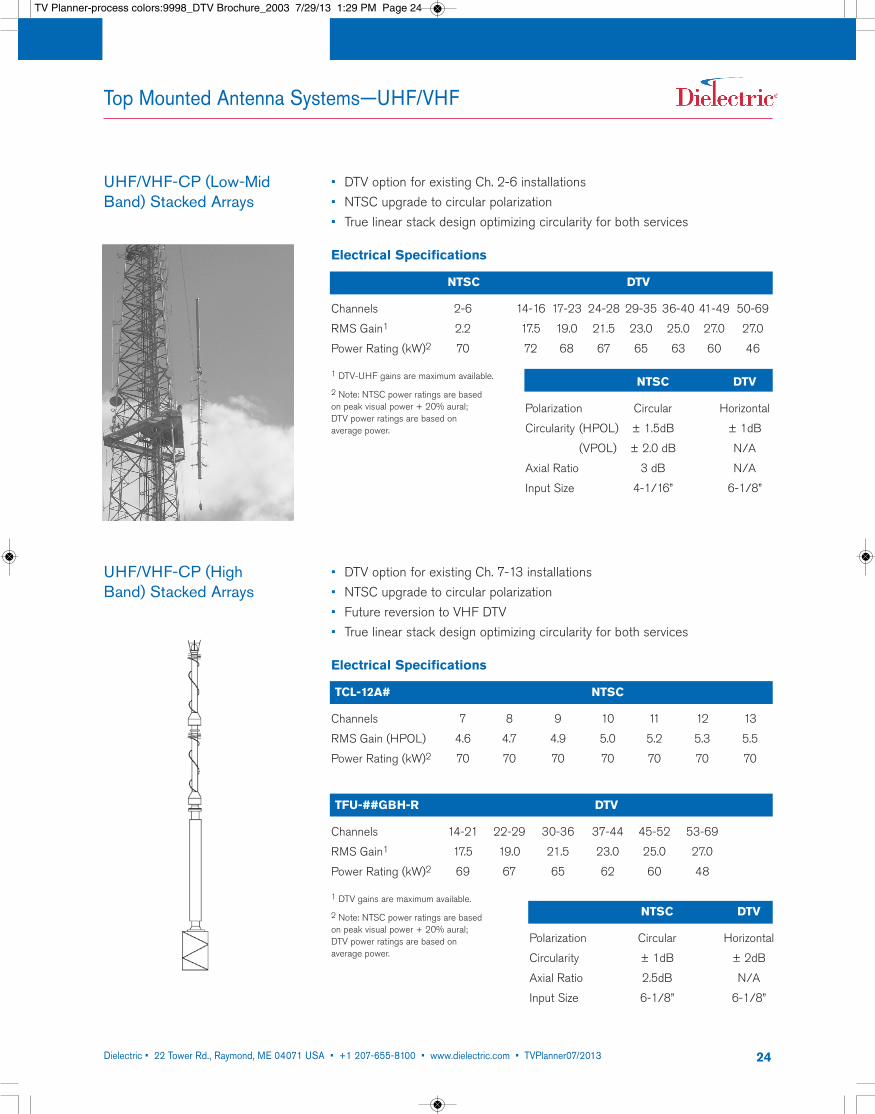
UHF/VHF-CP (Low-MidBand) Stacked Arrays
• DTV option for existing Ch. 2-6 installations• NTSC upgrade to circular polarization• True linear stack design optimizing circularity for both services
Electrical Specifications
NTSC DTV
Channels 2-6 14-16 17-23 24-28 29-35 36-40 41-49 50-69
RMS Gain1 2.2 17.5 19.0 21.5 23.0 25.0 27.0 27.0
Power Rating (kW)2 70 72 68 67 65 63 60 46
1 DTV-UHF gains are maximum available.
2 Note: NTSC power ratings are based on peak visual power + 20% aural; DTV power ratings are based on average power.
NTSC DTV
Polarization Circular Horizontal
Circularity (HPOL) ± 1.5dB ± 1dB
(VPOL) ± 2.0 dB N/A
Axial Ratio 3 dB N/A
Input Size 4-1/16” 6-1/8”
Top Mounted Antenna Systems—UHF/VHF
UHF/VHF-CP (HighBand) Stacked Arrays
• DTV option for existing Ch. 7-13 installations• NTSC upgrade to circular polarization• Future reversion to VHF DTV• True linear stack design optimizing circularity for both services
Electrical Specifications
TCL-12A# NTSC
Channels 7 8 9 10 11 12 13
RMS Gain (HPOL) 4.6 4.7 4.9 5.0 5.2 5.3 5.5
Power Rating (kW)2 70 70 70 70 70 70 70
TFU-##GBH-R DTV
Channels 14-21 22-29 30-36 37-44 45-52 53-69
RMS Gain1 17.5 19.0 21.5 23.0 25.0 27.0
Power Rating (kW)2 69 67 65 62 60 48
1 DTV gains are maximum available.
2 Note: NTSC power ratings are based on peak visual power + 20% aural; DTV power ratings are based on average power.
NTSC DTV
Polarization Circular Horizontal
Circularity ± 1dB ± 2dB
Axial Ratio 2.5dB N/A
Input Size 6-1/8” 6-1/8”
TV Planner-process colors:9998_DTV Brochure_2003 7/29/13 1:29 PM Page 24
Dielectric • 22 Tower Rd., Raymond, ME 04071 USA • +1 207-655-8100 • www.dielectric.com • TVPlanner07/2013 25
Side Mounted Antenna Systems—UHF
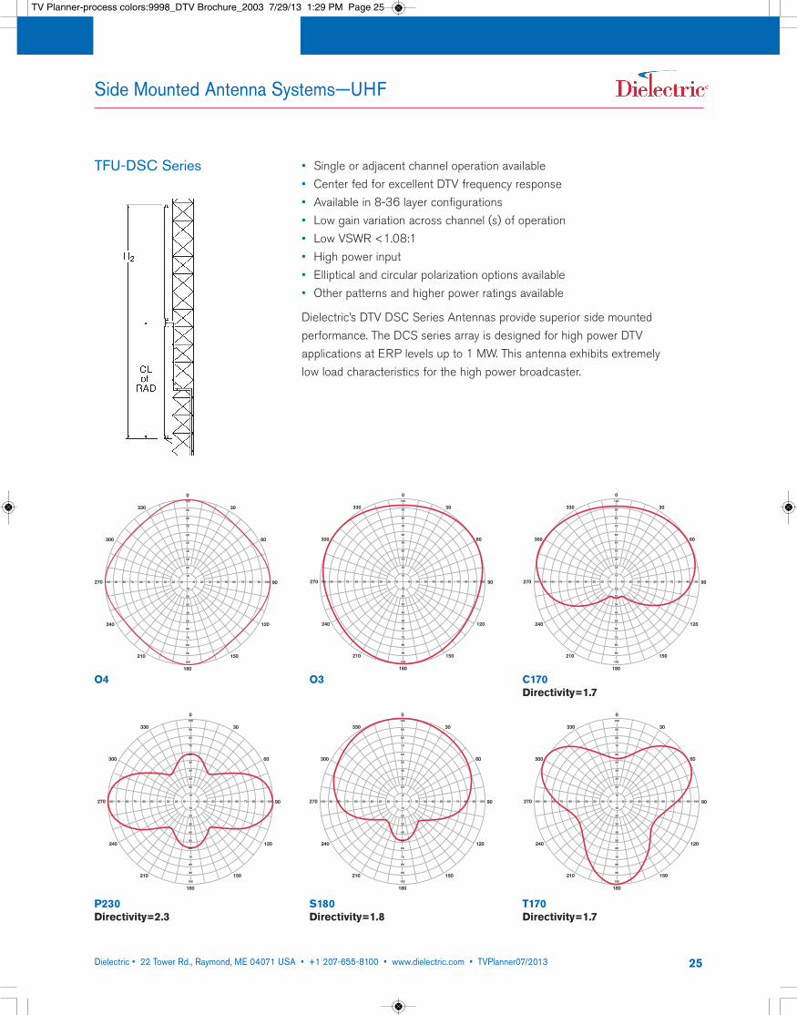
TFU-DSC Series • Single or adjacent channel operation available• Center fed for excellent DTV frequency response• Available in 8-36 layer configurations• Low gain variation across channel (s) of operation• Low VSWR <1.08:1• High power input• Elliptical and circular polarization options available• Other patterns and higher power ratings available
Dielectric’s DTV DSC Series Antennas provide superior side mounted performance. The DCS series array is designed for high power DTV applications at ERP levels up to 1 MW. This antenna exhibits extremely low load characteristics for the high power broadcaster.
330
300
270
240
210
180
150
120
90
60
30
0
20 30 40 50 60 70 80 90 100100 90 80 70 60 50 40 30 20 10 10
100
90
80
70
60
50
40
30
20
10
10
20
30
40
50
60
70
80
90
100
C170Directivity=1.7
O3
330
300
270
240
210
180
150
120
90
60
30
0
20 30 40 50 60 70 80 90 100100 90 80 70 60 50 40 30 20 10 10
100
90
80
70
60
50
40
30
20
10
10
20
30
40
50
60
70
80
90
100
S180Directivity=1.8
330
300
270
240
210
180
150
120
90
60
30
0
20 30 40 50 60 70 80 90 100100 90 80 70 60 50 40 30 20 10 10
100
90
80
70
60
50
40
30
20
10
10
20
30
40
50
60
70
80
90
100
T170Directivity=1.7
330
300
270
240
210
180
150
120
90
60
30
0
20 30 40 50 60 70 80 90 100100 90 80 70 60 50 40 30 20 10 10
100
90
80
70
60
50
40
30
20
10
10
20
30
40
50
60
70
80
90
100
P230Directivity=2.3
330
300
270
240
210
180
150
120
90
60
30
0
20 30 40 50 60 70 80 90 100100 90 80 70 60 50 40 30 20 10 10
100
90
80
70
60
50
40
30
20
10
10
20
30
40
50
60
70
80
90
100
O4
TV Planner-process colors:9998_DTV Brochure_2003 7/29/13 1:29 PM Page 25

Dielectric • 22 Tower Rd., Raymond, ME 04071 USA • +1 207-655-8100 • www.dielectric.com • TVPlanner07/2013 26
Side Mounted Antenna Systems—UHF
TFU-10DSC-R TFU-18DSC-R
1
0.9
0.8
0.7
0.6
0.5
0.4
0.3
0.2
0.1
0-3 -2 -1 0 1 2 3 4 5 6 7 8 9 10 11
Degrees below horizontal
1
0.9
0.8
0.7
0.6
0.5
0.4
0.3
0.2
0.1
0-3 -2 -1 0 1 2 3 4 5 6 7 8 9 10 11
Degress below horizontal
TFU-24DSC-R TFU-30DSC-R
1
0.9
0.8
0.7
0.6
0.5
0.4
0.3
0.2
0.1
0-3 -2 -1 0 1 2 3 4 5 6 7 8 9 10 11
Degrees below horizontal
1
0.9
0.8
0.7
0.6
0.5
0.4
0.3
0.2
0.1
0-3 -2 -1 0 1 2 3 4 5 6 7 8 9 10 11
Degrees below horizontal
9.5 (9.78dB) RMS Gain 15.0 (11.76dB) RMS Gain
19.5 (12.90dB) RMS Gain 25.5 (14.07dB) RMS Gain
Gain figures are for single channel operations. Contact factory for gain figures for dual channel operation.
TV Planner-process colors:9998_DTV Brochure_2003 7/29/13 1:29 PM Page 26
Dielectric • 22 Tower Rd., Raymond, ME 04071 USA • +1 207-655-8100 • www.dielectric.com • TVPlanner07/2013 27
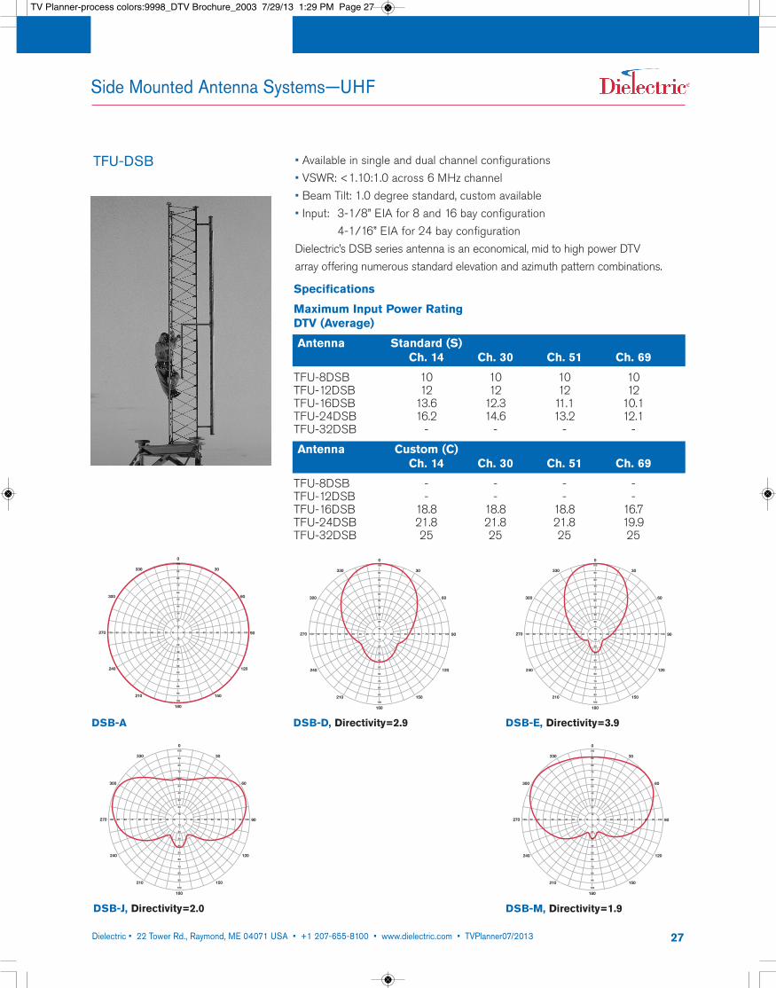
TFU-DSB • Available in single and dual channel configurations• VSWR: <1.10:1.0 across 6 MHz channel• Beam Tilt: 1.0 degree standard, custom available• Input: 3-1/8” EIA for 8 and 16 bay configuration
4-1/16” EIA for 24 bay configurationDielectric’s DSB series antenna is an economical, mid to high power DTV array offering numerous standard elevation and azimuth pattern combinations.
Specifications
Maximum Input Power Rating DTV (Average)
Antenna Standard (S)Ch. 14 Ch. 30 Ch. 51 Ch. 69
TFU-8DSB 10 10 10 10TFU-12DSB 12 12 12 12TFU-16DSB 13.6 12.3 11.1 10.1TFU-24DSB 16.2 14.6 13.2 12.1TFU-32DSB - - - -
Antenna Custom (C)Ch. 14 Ch. 30 Ch. 51 Ch. 69
TFU-8DSB - - - -TFU-12DSB - - - -TFU-16DSB 18.8 18.8 18.8 16.7TFU-24DSB 21.8 21.8 21.8 19.9TFU-32DSB 25 25 25 25
Side Mounted Antenna Systems—UHF
330
300
270
240
210
180
150
120
90
60
30
0
20 30 40 50 60 70 80 90 100100 90 80 70 60 50 40 30 20 10 10
100
90
80
70
60
50
40
30
20
10
10
20
30
40
50
60
70
80
90
100
DSB-D, Directivity=2.9
330
300
270
240
210
180
150
120
90
60
30
0
20 30 40 50 60 70 80 90 100100 90 80 70 60 50 40 30 20 10 10
100
90
80
70
60
50
40
30
20
10
10
20
30
40
50
60
70
80
90
100
DSB-E, Directivity=3.9
330
300
270
240
210
180
150
120
90
60
30
0100
90
80
70
60
50
40
30
20
10
10
20
30
40
50
60
70
80
90
100
100 90 80 70 60 50 40 30 20 10 10 20 30 40 50 60 70 80 90 100
DSB-J, Directivity=2.0
330
300
270
240
210
180
150
120
90
60
30
0100
90
80
70
60
50
40
30
20
10
10
20
30
40
50
60
70
80
90
100
20 30 40 50 60 70 80 90 100100 90 80 70 60 50 40 30 20 10 10
DSB-M, Directivity=1.9
330
300
270
240
210
180
150
120
90
60
30
0
20 30 40 50 60 70 80 90 100100 90 80 70 60 50 40 30 20 10 10
100
90
80
70
60
50
40
30
20
10
10
20
30
40
50
60
70
80
90
100
DSB-A
TV Planner-process colors:9998_DTV Brochure_2003 7/29/13 1:29 PM Page 27
Dielectric • 22 Tower Rd., Raymond, ME 04071 USA • +1 207-655-8100 • www.dielectric.com • TVPlanner07/2013 28
1
0.9
0.8
0.7
0.6
0.5
0.4
0.3
0.2
0.1
0-3 -2 -1 0 1 2 3 4 5 6 7 8 9 10 11
Degrees below horizontal
E
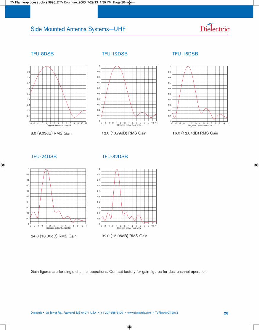
TFU-8DSB TFU-12DSB
1
0.9
0.8
0.7
0.6
0.5
0.4
0.3
0.2
0.1
0-3 -2 -1 0 1 2 3 4 5 6 7 8 9 10 11
Degrees below horizontal
E
8.0 (9.03dB) RMS Gain 12.0 (10.79dB) RMS Gain 16.0 (12.04dB) RMS Gain
TFU-16DSB
1
0.9
0.8
0.7
0.6
0.5
0.4
0.3
0.2
0.1
0-3 -2 -1 0 1 2 3 4 5 6 7 8 9 10 11
Degrees below horizontal
E
Side Mounted Antenna Systems—UHF
1
0.9
0.8
0.7
0.6
0.5
0.4
0.3
0.2
0.1
0-3 -2 -1 0 1 2 3 4 5 6 7 8 9 10 11
Degrees below horizontal
E
TFU-24DSB TFU-32DSB
1
0.9
0.8
0.7
0.6
0.5
0.4
0.3
0.2
0.1
0-3 -2 -1 0 1 2 3 4 5 6 7 8 9 10 11
Degrees below horizontal
E
24.0 (13.80dB) RMS Gain 32.0 (15.05dB) RMS Gain
Gain figures are for single channel operations. Contact factory for gain figures for dual channel operation.
TV Planner-process colors:9998_DTV Brochure_2003 7/29/13 1:30 PM Page 28
Dielectric • 22 Tower Rd., Raymond, ME 04071 USA • +1 207-655-8100 • www.dielectric.com • TVPlanner07/2013 29
Side Mounted Antenna Systems—UHF
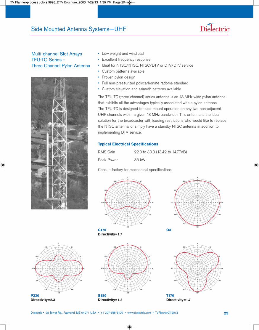
• Low weight and windload• Excellent frequency response• Ideal for NTSC/NTSC, NTSC/DTV or DTV/DTV service• Custom patterns available• Proven pylon design• Full non-pressurized polycarbonate radome standard• Custom elevation and azimuth patterns available
The TFU-TC (three channel) series antenna is an 18 MHz wide pylon antennathat exhibits all the advantages typically associated with a pylon antenna. The TFU-TC is designed for side mount operation on any two non-adjacentUHF channels within a given 18 MHz bandwidth. This antenna is the ideal solution for the broadcaster with loading restrictions who would like to replacethe NTSC antenna, or simply have a standby NTSC antenna in addition to implementing DTV service.
Typical Electrical Specifications
RMS Gain 22.0 to 30.0 (13.42 to 14.77dB)
Peak Power 85 kW
Consult factory for mechanical specifications.
330
300
270
240
210
180
150
120
90
60
30
0
20 30 40 50 60 70 80 90 100100 90 80 70 60 50 40 30 20 10 10
100
90
80
70
60
50
40
30
20
10
10
20
30
40
50
60
70
80
90
100
C170Directivity=1.7
O3
330
300
270
240
210
180
150
120
90
60
30
0
20 30 40 50 60 70 80 90 100100 90 80 70 60 50 40 30 20 10 10
100
90
80
70
60
50
40
30
20
10
10
20
30
40
50
60
70
80
90
100
S180Directivity=1.8
330
300
270
240
210
180
150
120
90
60
30
0
20 30 40 50 60 70 80 90 100100 90 80 70 60 50 40 30 20 10 10
100
90
80
70
60
50
40
30
20
10
10
20
30
40
50
60
70
80
90
100
T170Directivity=1.7
330
300
270
240
210
180
150
120
90
60
30
0
20 30 40 50 60 70 80 90 100100 90 80 70 60 50 40 30 20 10 10
100
90
80
70
60
50
40
30
20
10
10
20
30
40
50
60
70
80
90
100
P230Directivity=2.3
Multi-channel Slot ArraysTFU-TC Series - Three Channel Pylon Antenna
TV Planner-process colors:9998_DTV Brochure_2003 7/29/13 1:30 PM Page 29
Dielectric • 22 Tower Rd., Raymond, ME 04071 USA • +1 207-655-8100 • www.dielectric.com • TVPlanner07/2013 30
,
Side Mounted Antenna Systems—UHF
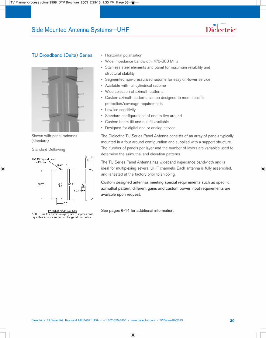
TU Broadband (Delta) Series • Horizontal polarization• Wide impedance bandwidth: 470-860 MHz• Stainless steel elements and panel for maximum reliability and structural stability
• Segmented non-pressurized radome for easy on-tower service• Available with full cylindrical radome• Wide selection of azimuth patterns• Custom azimuth patterns can be designed to meet specific protection/coverage requirements
• Low ice sensitivity• Standard configurations of one to five around• Custom beam tilt and null fill available• Designed for digital and or analog service
The Dielectric TU Series Panel Antenna consists of an array of panels typicallymounted in a four around configuration and supplied with a support structure.The number of panels per layer and the number of layers are variables used todetermine the azimuthal and elevation patterns.
The TU Series Panel Antenna has wideband impedance bandwidth and is ideal for multiplexing several UHF channels. Each antenna is fully assembled,and is tested at the factory prior to shipping.
Custom designed antennas meeting special requirements such as specificazimuthal pattern, different gains and custom power input requirements areavailable upon request.
See pages 6-14 for additional information.
Standard Deltawing
Shown with panel radomes (standard)
TV Planner-process colors:9998_DTV Brochure_2003 7/29/13 1:30 PM Page 30
Dielectric • 22 Tower Rd., Raymond, ME 04071 USA • +1 207-655-8100 • www.dielectric.com • TVPlanner07/2013 31
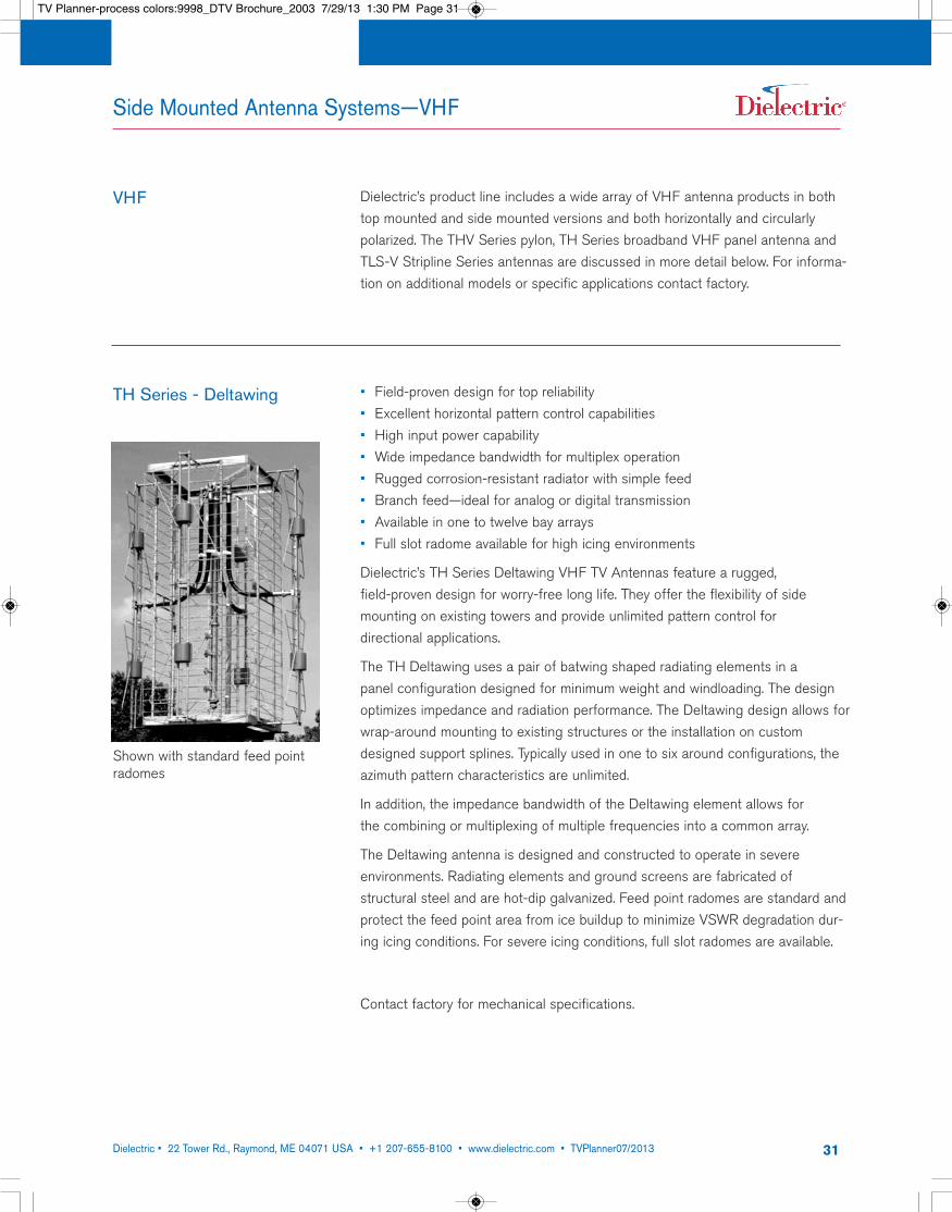
Dielectric’s product line includes a wide array of VHF antenna products in bothtop mounted and side mounted versions and both horizontally and circularlypolarized. The THV Series pylon, TH Series broadband VHF panel antenna andTLS-V Stripline Series antennas are discussed in more detail below. For informa-tion on additional models or specific applications contact factory.
• Field-proven design for top reliability• Excellent horizontal pattern control capabilities• High input power capability• Wide impedance bandwidth for multiplex operation• Rugged corrosion-resistant radiator with simple feed• Branch feed—ideal for analog or digital transmission• Available in one to twelve bay arrays• Full slot radome available for high icing environments
Dielectric’s TH Series Deltawing VHF TV Antennas feature a rugged, field-proven design for worry-free long life. They offer the flexibility of sidemounting on existing towers and provide unlimited pattern control for directional applications.
The TH Deltawing uses a pair of batwing shaped radiating elements in a panel configuration designed for minimum weight and windloading. The designoptimizes impedance and radiation performance. The Deltawing design allows forwrap-around mounting to existing structures or the installation on customdesigned support splines. Typically used in one to six around configurations, theazimuth pattern characteristics are unlimited.
In addition, the impedance bandwidth of the Deltawing element allows for the combining or multiplexing of multiple frequencies into a common array.
The Deltawing antenna is designed and constructed to operate in severe environments. Radiating elements and ground screens are fabricated of structural steel and are hot-dip galvanized. Feed point radomes are standard andprotect the feed point area from ice buildup to minimize VSWR degradation dur-ing icing conditions. For severe icing conditions, full slot radomes are available.
TH Series - Deltawing
Contact factory for mechanical specifications.
Side Mounted Antenna Systems—VHF
VHF
Shown with standard feed pointradomes
TV Planner-process colors:9998_DTV Brochure_2003 7/29/13 1:30 PM Page 31
Dielectric • 22 Tower Rd., Raymond, ME 04071 USA • +1 207-655-8100 • www.dielectric.com • TVPlanner07/2013 32
Side Mounted Antenna Systems—VHF
330
300
270
240
210
180
150
120
90
60
30
0
20 30 40 50 60 70 80 90 100100 90 80 70 60 50 40 30 20 10 10
100
90
80
70
60
50
40
30
20
10
10
20
30
40
50
60
70
80
90
100
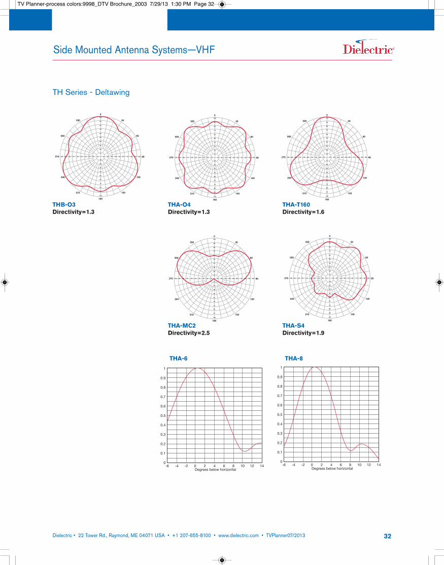
THB-O3Directivity=1.3
330
300
270
240
210
180
150
120
90
60
30
0
20 30 40 50 60 70 80 90 100100 90 80 70 60 50 40 30 20 10 10
100
90
80
70
60
50
40
30
20
10
10
20
30
40
50
60
70
80
90
100
THA-T160Directivity=1.6
330
300
270
240
210
180
150
120
90
60
30
0
20 30 40 50 60 70 80 90 100100 90 80 70 60 50 40 30 20 10 10
100
90
80
70
60
50
40
30
20
10
10
20
30
40
50
60
70
80
90
100
THA-O4Directivity=1.3
330
300
270
240
210
180
150
120
90
60
30
0
20 30 40 50 60 70 80 90 100100 90 80 70 60 50 40 30 20 10 10
100
90
80
70
60
50
40
30
20
10
10
20
30
40
50
60
70
80
90
100
THA-MC2Directivity=2.5
330
300
270
240
210
180
150
120
90
60
30
0
20 30 40 50 60 70 80 90 100100 90 80 70 60 50 40 30 20 10 10
100
90
80
70
60
50
40
30
20
10
10
20
30
40
50
60
70
80
90
100
THA-S4Directivity=1.9
TH Series - Deltawing
1
0.9
0.8
0.7
0.6
0.5
0.4
0.3
0.2
0.1
0-6 -4 -2 0 2 4 6 8 10 12 14
Degrees below horizontal
E
Beam Tilt .
1
0.9
0.8
0.7
0.6
0.5
0.4
0.3
0.2
0.1
0-6 -4 -2 0 2 4 6 8 10 12 14
Degrees below horizontal
E
Beam Tilt . THA-6 THA-8
TV Planner-process colors:9998_DTV Brochure_2003 7/29/13 1:30 PM Page 32
Dielectric • 22 Tower Rd., Raymond, ME 04071 USA • +1 207-655-8100 • www.dielectric.com • TVPlanner07/2013 33
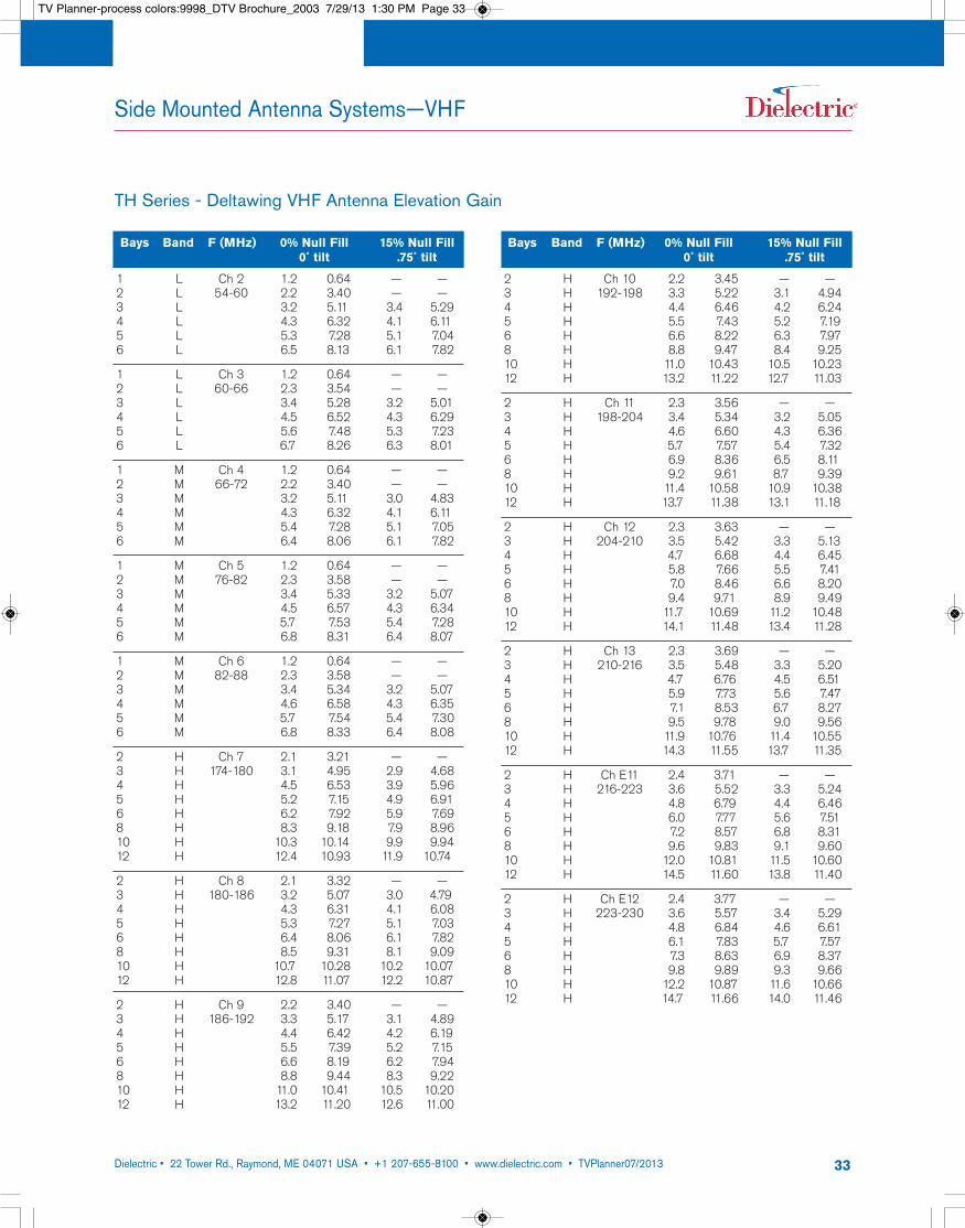
TH Series - Deltawing VHF Antenna Elevation Gain
Bays Band F (MHz) 0% Null Fill 15% Null Fill0˚ tilt .75˚ tilt
1 L Ch 2 1.2 0.64 — —2 L 54-60 2.2 3.40 — —3 L 3.2 5.11 3.4 5.294 L 4.3 6.32 4.1 6.115 L 5.3 7.28 5.1 7.046 L 6.5 8.13 6.1 7.82
1 L Ch 3 1.2 0.64 — —2 L 60-66 2.3 3.54 — —3 L 3.4 5.28 3.2 5.014 L 4.5 6.52 4.3 6.295 L 5.6 7.48 5.3 7.236 L 6.7 8.26 6.3 8.01
1 M Ch 4 1.2 0.64 — —2 M 66-72 2.2 3.40 — —3 M 3.2 5.11 3.0 4.834 M 4.3 6.32 4.1 6.115 M 5.4 7.28 5.1 7.056 M 6.4 8.06 6.1 7.82
1 M Ch 5 1.2 0.64 — —2 M 76-82 2.3 3.58 — —3 M 3.4 5.33 3.2 5.074 M 4.5 6.57 4.3 6.345 M 5.7 7.53 5.4 7.286 M 6.8 8.31 6.4 8.07
1 M Ch 6 1.2 0.64 — —2 M 82-88 2.3 3.58 — —3 M 3.4 5.34 3.2 5.074 M 4.6 6.58 4.3 6.355 M 5.7 7.54 5.4 7.306 M 6.8 8.33 6.4 8.08
2 H Ch 7 2.1 3.21 — —3 H 174-180 3.1 4.95 2.9 4.684 H 4.5 6.53 3.9 5.965 H 5.2 7.15 4.9 6.916 H 6.2 7.92 5.9 7.698 H 8.3 9.18 7.9 8.9610 H 10.3 10.14 9.9 9.9412 H 12.4 10.93 11.9 10.74
2 H Ch 8 2.1 3.32 — —3 H 180-186 3.2 5.07 3.0 4.794 H 4.3 6.31 4.1 6.085 H 5.3 7.27 5.1 7.036 H 6.4 8.06 6.1 7.828 H 8.5 9.31 8.1 9.0910 H 10.7 10.28 10.2 10.0712 H 12.8 11.07 12.2 10.87
2 H Ch 9 2.2 3.40 — —3 H 186-192 3.3 5.17 3.1 4.894 H 4.4 6.42 4.2 6.195 H 5.5 7.39 5.2 7.156 H 6.6 8.19 6.2 7.948 H 8.8 9.44 8.3 9.2210 H 11.0 10.41 10.5 10.2012 H 13.2 11.20 12.6 11.00
Bays Band F (MHz) 0% Null Fill 15% Null Fill0˚ tilt .75˚ tilt
2 H Ch 10 2.2 3.45 — —3 H 192-198 3.3 5.22 3.1 4.944 H 4.4 6.46 4.2 6.245 H 5.5 7.43 5.2 7.196 H 6.6 8.22 6.3 7.978 H 8.8 9.47 8.4 9.2510 H 11.0 10.43 10.5 10.2312 H 13.2 11.22 12.7 11.03
2 H Ch 11 2.3 3.56 — —3 H 198-204 3.4 5.34 3.2 5.054 H 4.6 6.60 4.3 6.365 H 5.7 7.57 5.4 7.326 H 6.9 8.36 6.5 8.118 H 9.2 9.61 8.7 9.3910 H 11.4 10.58 10.9 10.3812 H 13.7 11.38 13.1 11.18
2 H Ch 12 2.3 3.63 — —3 H 204-210 3.5 5.42 3.3 5.134 H 4.7 6.68 4.4 6.455 H 5.8 7.66 5.5 7.416 H 7.0 8.46 6.6 8.208 H 9.4 9.71 8.9 9.4910 H 11.7 10.69 11.2 10.4812 H 14.1 11.48 13.4 11.28
2 H Ch 13 2.3 3.69 — —3 H 210-216 3.5 5.48 3.3 5.204 H 4.7 6.76 4.5 6.515 H 5.9 7.73 5.6 7.476 H 7.1 8.53 6.7 8.278 H 9.5 9.78 9.0 9.5610 H 11.9 10.76 11.4 10.5512 H 14.3 11.55 13.7 11.35
2 H Ch E11 2.4 3.71 — —3 H 216-223 3.6 5.52 3.3 5.244 H 4.8 6.79 4.4 6.465 H 6.0 7.77 5.6 7.516 H 7.2 8.57 6.8 8.318 H 9.6 9.83 9.1 9.6010 H 12.0 10.81 11.5 10.6012 H 14.5 11.60 13.8 11.40
2 H Ch E12 2.4 3.77 — —3 H 223-230 3.6 5.57 3.4 5.294 H 4.8 6.84 4.6 6.615 H 6.1 7.83 5.7 7.576 H 7.3 8.63 6.9 8.378 H 9.8 9.89 9.3 9.6610 H 12.2 10.87 11.6 10.6612 H 14.7 11.66 14.0 11.46
Side Mounted Antenna Systems—VHF
TV Planner-process colors:9998_DTV Brochure_2003 7/29/13 1:30 PM Page 33
Dielectric • 22 Tower Rd., Raymond, ME 04071 USA • +1 207-655-8100 • www.dielectric.com • TVPlanner07/2013 34
TLS-V Series
Side Mounted Antenna Systems—VHF
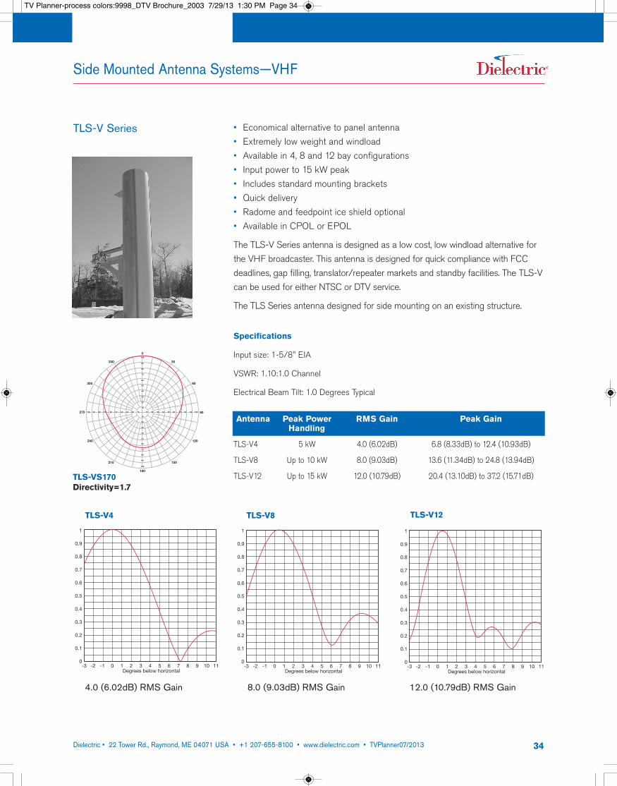
• Economical alternative to panel antenna• Extremely low weight and windload• Available in 4, 8 and 12 bay configurations• Input power to 15 kW peak• Includes standard mounting brackets• Quick delivery• Radome and feedpoint ice shield optional• Available in CPOL or EPOL
The TLS-V Series antenna is designed as a low cost, low windload alternative forthe VHF broadcaster. This antenna is designed for quick compliance with FCCdeadlines, gap filling, translator/repeater markets and standby facilities. The TLS-Vcan be used for either NTSC or DTV service.
The TLS Series antenna designed for side mounting on an existing structure.
Antenna Peak Power RMS Gain Peak GainHandling
TLS-V4 5 kW 4.0 (6.02dB) 6.8 (8.33dB) to 12.4 (10.93dB)
TLS-V8 Up to 10 kW 8.0 (9.03dB) 13.6 (11.34dB) to 24.8 (13.94dB)
TLS-V12 Up to 15 kW 12.0 (10.79dB) 20.4 (13.10dB) to 37.2 (15.71dB)
Specifications
Input size: 1-5/8" EIA
VSWR: 1.10:1.0 Channel
Electrical Beam Tilt: 1.0 Degrees Typical
330
300
270
240
210
180
150
120
90
60
30
0
20 30 40 50 60 70 80 90 100100 90 80 70 60 50 40 30 20 10 10
100
90
80
70
60
50
40
30
20
10
10
20
30
40
50
60
70
80
90
100
TLS-VS170Directivity=1.7
1
0.9
0.8
0.7
0.6
0.5
0.4
0.3
0.2
0.1
0-3 -2 -1 0 1 2 3 4 5 6 7 8 9 10 11
Degrees below horizontal
E
TLS-V4
1
0.9
0.8
0.7
0.6
0.5
0.4
0.3
0.2
0.1
0-3 -2 -1 0 1 2 3 4 5 6 7 8 9 10 11
Degrees below horizontal
E
TLS-V8
1
0.9
0.8
0.7
0.6
0.5
0.4
0.3
0.2
0.1
0-3 -2 -1 0 1 2 3 4 5 6 7 8 9 10 11
Degrees below horizontal
E
TLS-V12
4.0 (6.02dB) RMS Gain 8.0 (9.03dB) RMS Gain 12.0 (10.79dB) RMS Gain
TV Planner-process colors:9998_DTV Brochure_2003 7/29/13 1:30 PM Page 34
Dielectric • 22 Tower Rd., Raymond, ME 04071 USA • +1 207-655-8100 • www.dielectric.com • TVPlanner07/2013 35
Global Presence
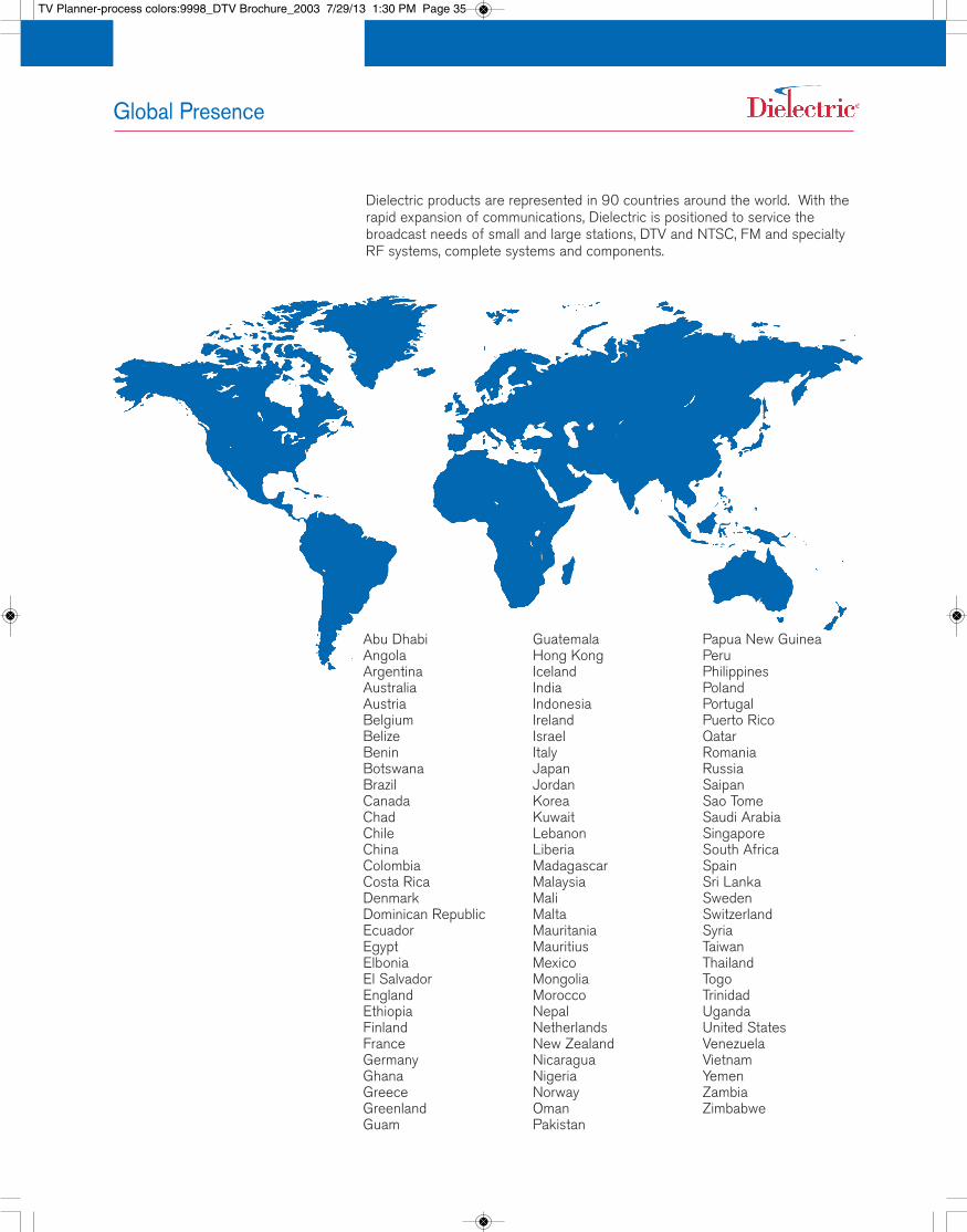
Dielectric products are represented in 90 countries around the world. With therapid expansion of communications, Dielectric is positioned to service thebroadcast needs of small and large stations, DTV and NTSC, FM and specialtyRF systems, complete systems and components.
Abu DhabiAngolaArgentinaAustraliaAustriaBelgiumBelizeBeninBotswanaBrazilCanadaChadChileChinaColombiaCosta RicaDenmarkDominican RepublicEcuadorEgyptElboniaEl SalvadorEnglandEthiopiaFinlandFranceGermanyGhanaGreeceGreenlandGuam
GuatemalaHong KongIcelandIndiaIndonesiaIrelandIsraelItalyJapanJordanKoreaKuwaitLebanonLiberiaMadagascarMalaysiaMaliMaltaMauritaniaMauritiusMexicoMongoliaMoroccoNepalNetherlandsNew ZealandNicaraguaNigeriaNorwayOmanPakistan
Papua New GuineaPeruPhilippinesPolandPortugalPuerto RicoQatarRomaniaRussiaSaipanSao TomeSaudi ArabiaSingaporeSouth AfricaSpainSri LankaSwedenSwitzerlandSyriaTaiwanThailandTogoTrinidadUgandaUnited StatesVenezuelaVietnamYemenZambiaZimbabwe
TV Planner-process colors:9998_DTV Brochure_2003 7/29/13 1:30 PM Page 35