Embed Size (px)
Citation preview

TW-3G Flash-OFDM Router
3G Flash-OFDM Router (USB and PC Card interfaces)
Wireless access Point 802.11b/g 54 Mbps
User Guide

2
3
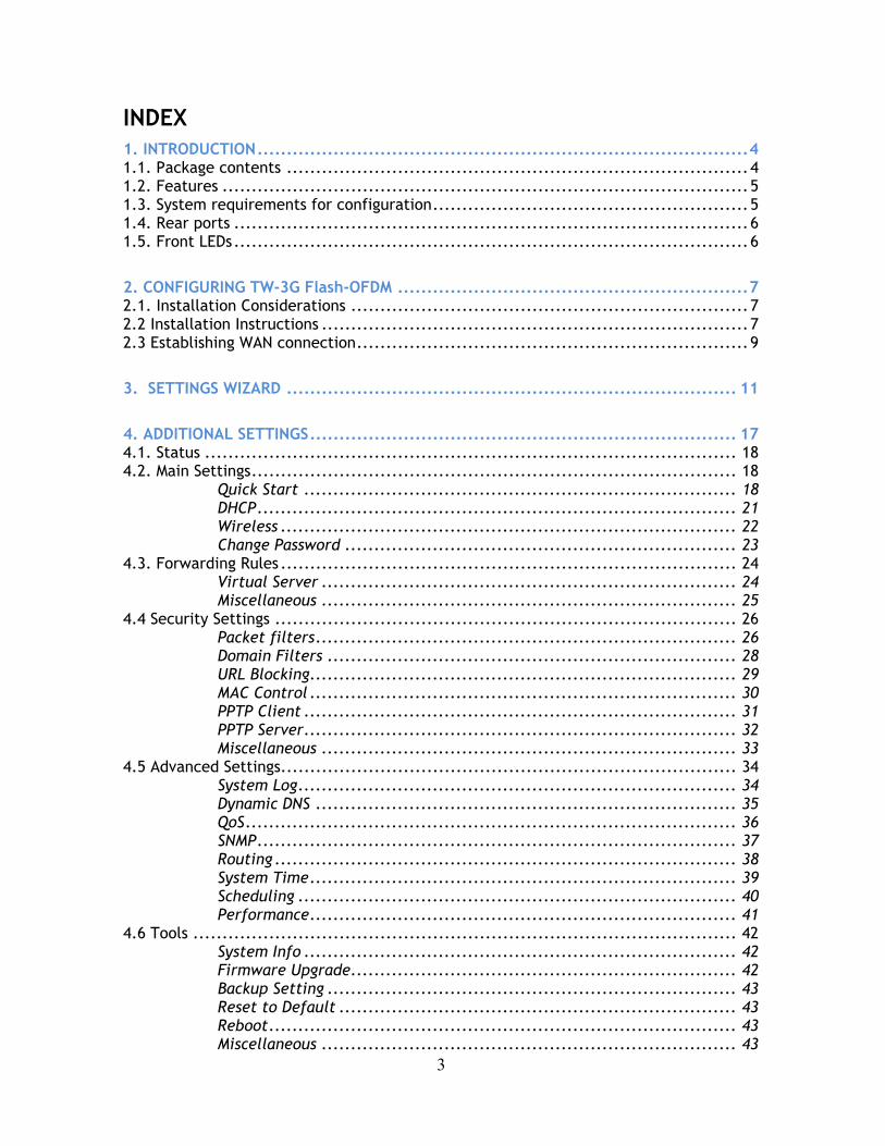
INDEX 1. INTRODUCTION....................................................................................4 1.1. Package contents ...............................................................................4 1.2. Features ..........................................................................................5 1.3. System requirements for configuration......................................................5 1.4. Rear ports ........................................................................................6 1.5. Front LEDs........................................................................................6
2. CONFIGURING TW-3G Flash-OFDM ............................................................7 2.1. Installation Considerations ....................................................................7 2.2 Installation Instructions .........................................................................7 2.3 Establishing WAN connection...................................................................9
3. SETTINGS WIZARD ............................................................................. 11
4. ADDITIONAL SETTINGS......................................................................... 17 4.1. Status ........................................................................................... 18 4.2. Main Settings................................................................................... 18
Quick Start .......................................................................... 18 DHCP.................................................................................. 21 Wireless .............................................................................. 22 Change Password ................................................................... 23
4.3. Forwarding Rules .............................................................................. 24 Virtual Server ....................................................................... 24 Miscellaneous ....................................................................... 25
4.4 Security Settings ............................................................................... 26 Packet filters........................................................................ 26 Domain Filters ...................................................................... 28 URL Blocking......................................................................... 29 MAC Control ......................................................................... 30 PPTP Client .......................................................................... 31 PPTP Server.......................................................................... 32 Miscellaneous ....................................................................... 33
4.5 Advanced Settings.............................................................................. 34 System Log........................................................................... 34 Dynamic DNS ........................................................................ 35 QoS.................................................................................... 36 SNMP.................................................................................. 37 Routing ............................................................................... 38 System Time......................................................................... 39 Scheduling ........................................................................... 40 Performance......................................................................... 41
4.6 Tools ............................................................................................. 42 System Info .......................................................................... 42 Firmware Upgrade.................................................................. 42 Backup Setting ...................................................................... 43 Reset to Default .................................................................... 43 Reboot................................................................................ 43 Miscellaneous ....................................................................... 43

4
1. INTRODUCTION With TeleWell TW-3G+WLAN Router it's possible to share one 3G or Flash-OFDM connection to multiple PC's. Device includes both USB and PC Card interfaces for 3G or Flash-OFDM card (not included). 3G or Flash-OFDM connection can be used via Ethernet or Wlan interfaces. It's also possible to share xDSL connection by connecting extrenal xDSL modem* to the devices WAN port. 3G or Flash-OFDM connection can be used as main WAN connection or as secondary backup connection for external xDSL. When used as backup connection, in case of main WAN xDSL connection failure device can automatically connect to 3G or Flash-OFDM network.
1.1. Package contents
TW-3G Flash-OFDM Router package should contain the items listed below. If any of the items are missing, please contact your reseller. • TW-3G Flash-OFDM Router • RJ45 cable • Power adapter 5V 3A • Manual
Caution: Using a power supply with a different voltage rating than the one included with the TW-3G Flash-OFDM Router will cause damage and void the warranty for this product.

5
1.2. Features
• Automatic take over back up with 3G connection as Ethernet WAN failover.
• Implementation within 3 minutes allows the network to go where wires cannot go – even outside the home or office.
• Fully compatible with the 802.11g standard to provide a wireless data transfer rate of up to 54Mbps.
• Backwards compatible with the 802.11b standard to provide a wireless data rate of up to 11Mbps.
• Utilizes OFDM technology (Orthogonal Frequency Division Multiplexing). • User-friendly configuration and diagnostic utilities. • Operates in the 2.4GHz frequency range. • Advanced Firewall features. • Supports NAT with VPN pass-through, providing added security.
o MAC Filtering o IP Filtering o Port Scheduling
• DHCP server enables all networked computers to automatically receive IP addresses.
• Web-based interface for Managing and Configuring. • Access Control to manage users on the network. • Supports special applications that require multiple connections. • Equipped with 2*10/100 Ethernet ports, for LAN and WAN access, and a
Type II PC card (for both 16-Bit and 32Bit) Slot or USB port for 3G network connection.
• Connects multiple computers to a Broadband either WCDMA or EV-DO even HSDPA modem to share the Internet connection.
Note: TW-3G Flash-OFDM Router is designed to work with either EVDO or WCDMA (UMTS) even up to 3.5G HSPA PC interface. Please refer to your service provider for detailed feature information.
1.3. System requirements for configuration
• A compatible either 16-bit or 32-bit PCMCIA or USB 3G modem card with service Note: Subject to services and service terms available from your carrier. • Computers with Windows, Macintosh, or Linux-based operating systems with an installed Ethernet adapter. • Internet Explorer version 6.0 or Netscape Navigator version 7.0 and above.
WiFi System Requirements
• A 802.11b, 802.11g Adapter

6
1.4. Rear ports
ANTENNA
WAN WAN port for ADSL cable
LAN LAN port for Ethernet cable
USB USB port for connecting with 3G USB modem
RESET Restore to Original factory default settingS
POWER Receptor for Power adapter
1.5. Front LEDs
3G Green light as power is on and ready
LAN Green light as connected to local Ethernet and blinks during data transmission
WAN Green light as WAN is connected
WiFi Green light when connection on WLAN available
7
2. CONFIGURING TW-3G Flash-OFDM 2.1. Installation Considerations
TW-3G Flash-OFDM Router allows you access your network using a wireless connection, from virtually anywhere within its operating range. Keep in mind however, that the number, thickness, and location of walls, ceilings, or other objects that the wireless signals must pass through, may limit this range. Typical ranges vary depending on the types of materials used, and background RF (radio frequency) noise in your home or business. To maximize your wireless range, please follow these guidelines: 1. Keep the number of walls and ceilings between the TW-3G Flash-OFDM
Router and other network devices to a minimum. Each wall or ceiling can reduce the TW-3G Flash-OFDM Router’s range from 3-90 feet (1-30 meters). Note: The same considerations apply to your broadband EVDO connection.
2. Keep your product aware from electrical devices (such as microwaves, air conditioners, and televisions) that emit large quantities of RFI (Radio Frequency Interference).
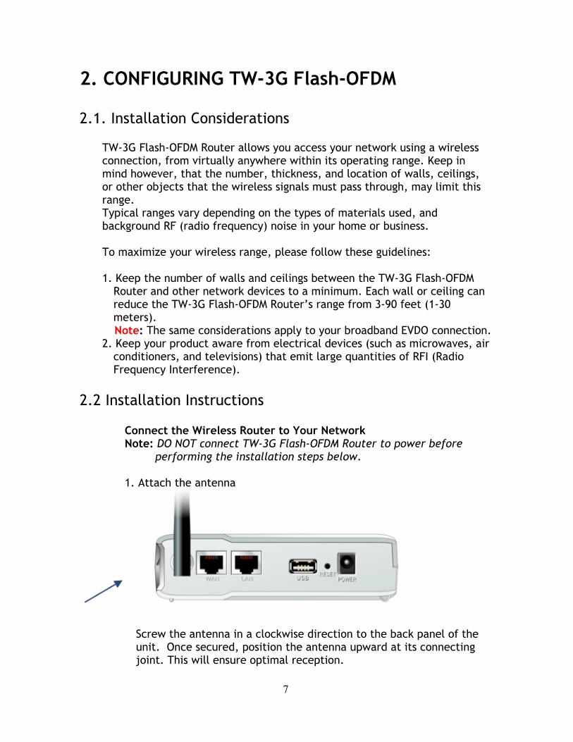
2.2 Installation Instructions Connect the Wireless Router to Your Network Note: DO NOT connect TW-3G Flash-OFDM Router to power before
performing the installation steps below. 1. Attach the antenna
Screw the antenna in a clockwise direction to the back panel of the unit. Once secured, position the antenna upward at its connecting joint. This will ensure optimal reception.

8
2. Connect a compatible Type II 3G cards or USB modem with service to the TW-3G Flash-OFDM Router in one of the following ways: - Insert your wireless Type II 3G card (either 16-bit or 32-bit ) into
the WAN PCMCIA Card Slot or you can plug your USB modem into the USB interface.
3. Insert the Ethernet patch cable into LAN Port on the back panel of
the TW-3G Flash-OFDM Router, and an available Ethernet port on the network adapter in the computer you will use to configure the unit.
4. Connect the power adapter to the receptor on the back panel of your
TW-3G Flash-OFDM Router. Then plug the other end of the power adapter into a wall outlet or power strip.
The Power LED will turn ON to indicate power has been applied. Other LEDs will flash ON and OFF as the TW-3G Flash-OFDM Router performs initialization and Internet connection processes. This will take a few minutes. When complete, the following LEDs will illuminate green: M1, WAN, LAN, and WiFi

9
2.3 Establishing WAN connection Once properly configured, TW-3G Flash-OFDM Router will obtain and assign IP address information automatically. Configuration settings can be established through the TW-3G Flash-OFDM Router Configuration Menu. You can access this interface by performing the steps listed below: NOTE: THE ROUTERS SETTINGS SHOULD ONLY BE MODEFIED VIA ETHERNET CABLE; NOT THROUGH WIRELESS CONNECTION! 1. Open a web-browser.
2. Type in the IP Address (http://192.168.0.254) of the TW-3G Flash-OFDM Router Note: If you have changed the default IP Address assigned to the TW-3G Flash-OFDM Router, ensure you enter the correct IP Address now.
3. The default language of the web GUI is Finnish. You can change the
language settings after logging in. Type “admin” in the Password field (Järjestelmän salasana).
-> Click “logon” button (Kirjaudu).
10
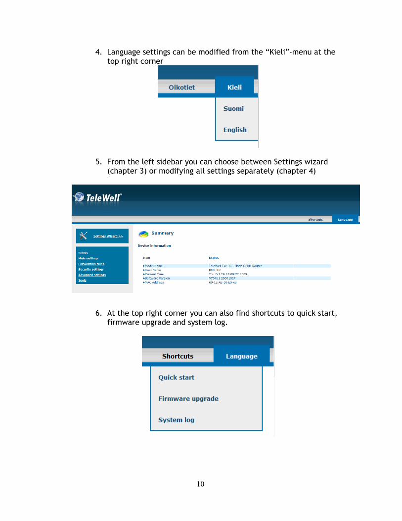
4. Language settings can be modified from the “Kieli”-menu at the top right corner
5. From the left sidebar you can choose between Settings wizard (chapter 3) or modifying all settings separately (chapter 4)
6. At the top right corner you can also find shortcuts to quick start, firmware upgrade and system log.
11
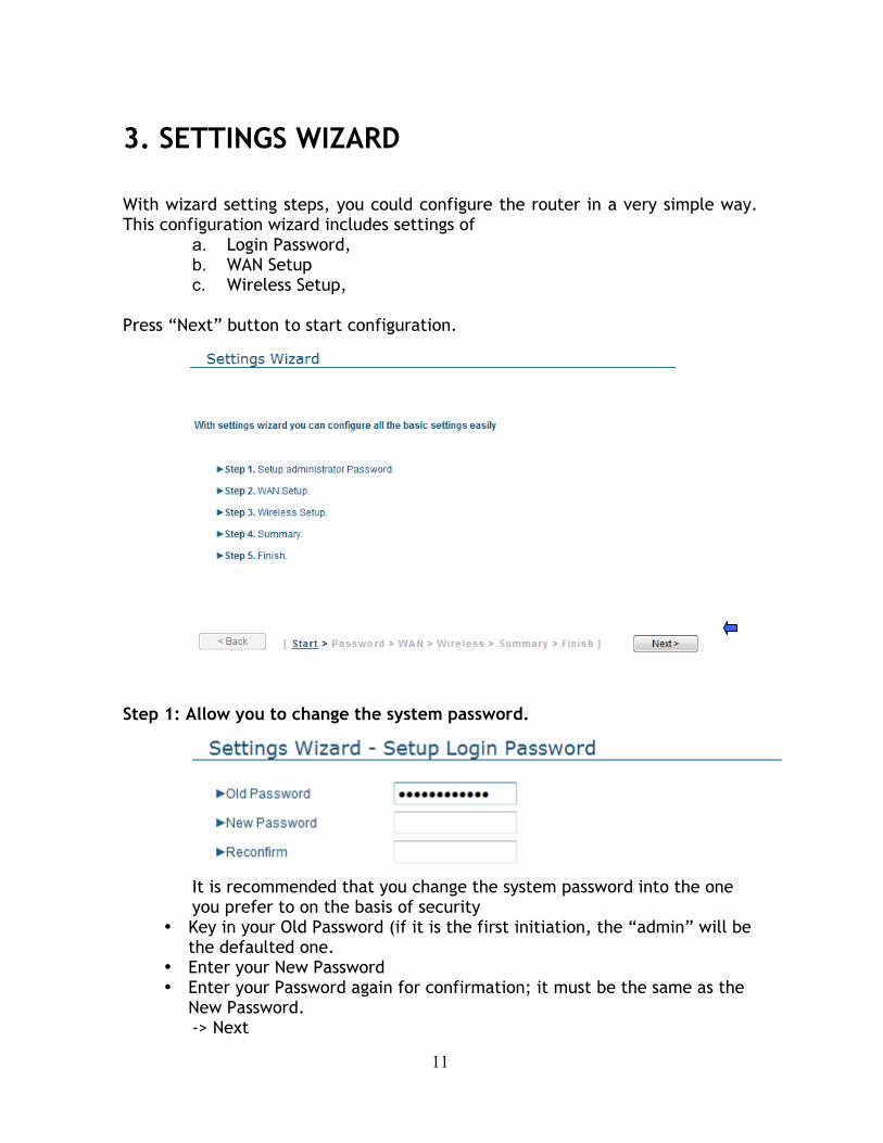
3. SETTINGS WIZARD With wizard setting steps, you could configure the router in a very simple way. This configuration wizard includes settings of
a. Login Password, b. WAN Setup c. Wireless Setup,
Press “Next” button to start configuration.
Step 1: Allow you to change the system password.
It is recommended that you change the system password into the one you prefer to on the basis of security
• Key in your Old Password (if it is the first initiation, the “admin” will be the defaulted one.
• Enter your New Password • Enter your Password again for confirmation; it must be the same as the
New Password. -> Next

12
Step 2:Select WAN Types will be used for Internet connection
-> Next
Step 3:If chosen 3G, configure the 3G settings
• APN: Enter the APN for your PC card here. • Pin Code: Enter the Pin Code for your PC card • Dialed Number: This field should not be altered except when required
by your service provider. • Username: Enter the new Username for your PC card here. • Password: Enter the new Password for your PC card here. • Primary DNS: This feature allows you to assign a Primary DNS
Server(Optional) • Secondary DNS: This feature allows you to assign a Secondary DNS
Server(Optional) • Maximum Idle Time: The Connection will be broken when the idle time
arrives.
-> Next
13
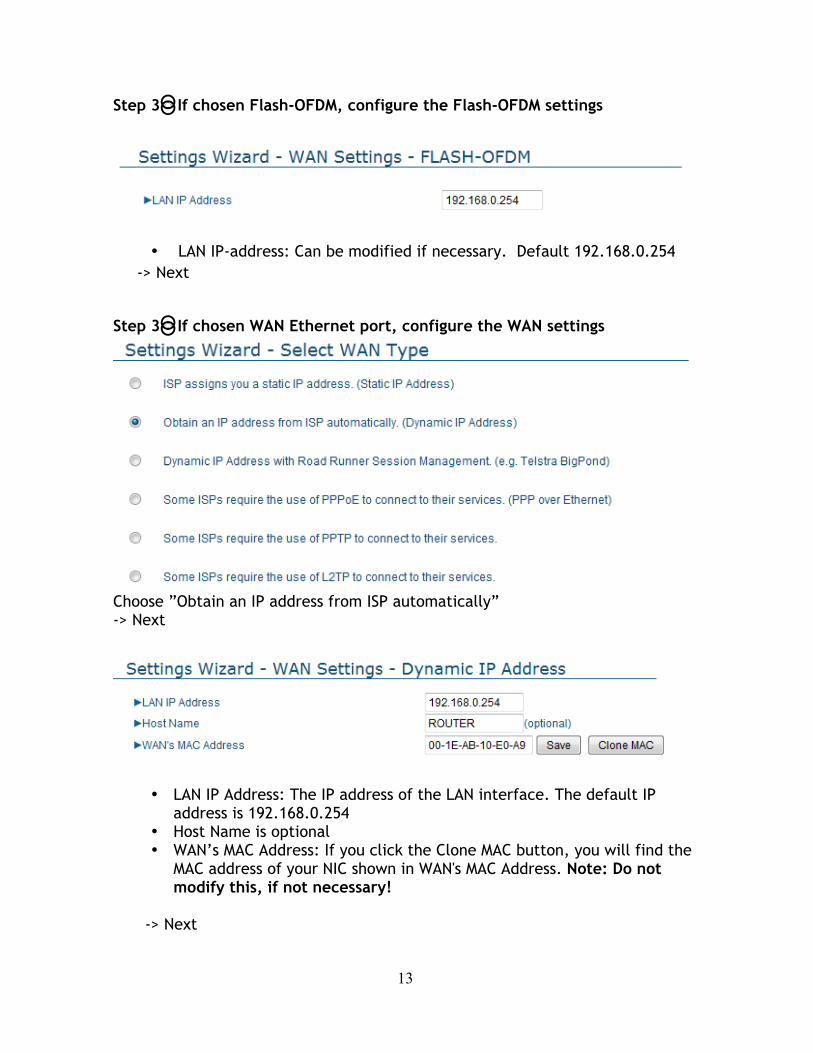
Step 3:If chosen Flash-OFDM, configure the Flash-OFDM settings
• LAN IP-address: Can be modified if necessary. Default 192.168.0.254 -> Next
Step 3:If chosen WAN Ethernet port, configure the WAN settings
Choose ”Obtain an IP address from ISP automatically” -> Next
• LAN IP Address: The IP address of the LAN interface. The default IP address is 192.168.0.254
• Host Name is optional • WAN’s MAC Address: If you click the Clone MAC button, you will find the
MAC address of your NIC shown in WAN's MAC Address. Note: Do not modify this, if not necessary!
-> Next
14
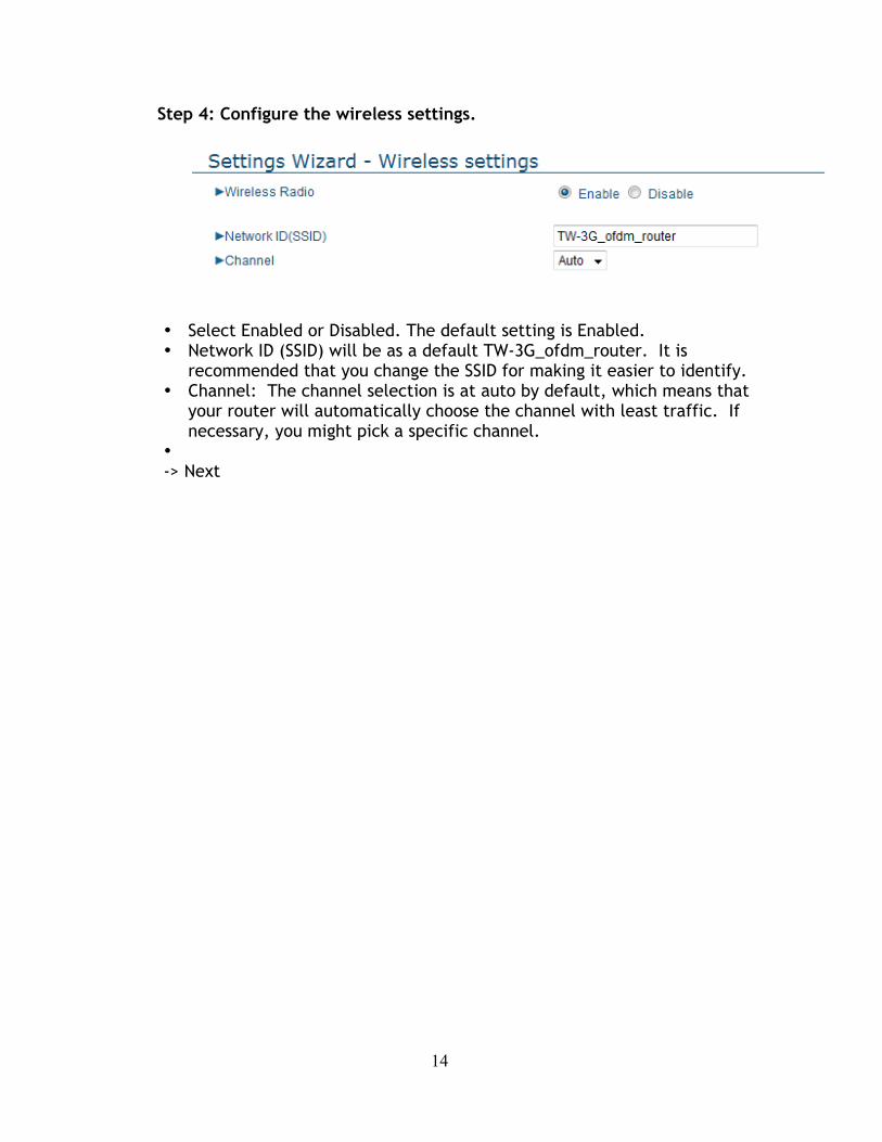
Step 4: Configure the wireless settings.
• Select Enabled or Disabled. The default setting is Enabled. • Network ID (SSID) will be as a default TW-3G_ofdm_router. It is
recommended that you change the SSID for making it easier to identify. • Channel: The channel selection is at auto by default, which means that
your router will automatically choose the channel with least traffic. If necessary, you might pick a specific channel.
• -> Next

15
Step 5: Select the Wireless security method of your wireless configuration.
• Security: Security type for your wireless connection. The secirity is
disabled by default, but is very strongly recommended to enable it. • WPA-PSK or WPA2-PSK are recommended. They perform better than
WEP. Note: your computer’s network card must support the chosen security type.
• WPA-PSK / WPA2-PSK: Choose encryption type, TKIP tai AES. With
WPA-PSK you should choose TKIP-encryption, with WPA2-PSK-you shoudl choose AES-encryption. The password lenght is 6-63 letters or numbers.
• WEP: Choose between 64 / 128 bits, and hexadecimals / ASCII 64 bits + HEX= 10 numbers 128 bits + HEX= 26 numbers 64 bits + ASCII= 5 letters or numbers 128 bits + ASCII= 13 letters or numbers
Type your password in ”Key 1” slot.
-> Next

16
Step 6: Summary
Make sure that the settings are correctly. By clicking ”Back” you can go back to change the settings. -> Apply Settings
Please wait patiently while the settings are saved. Once they’ve been saved the router will reboot, and you will automatically logout. After that you may log back in to ensure on the front page that the settings were correctly updated.
17
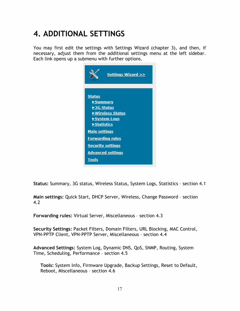
4. ADDITIONAL SETTINGS
You may first edit the settings with Settings Wizard (chapter 3), and then, if necessary, adjust them from the additional settings menu at the left sidebar. Each link opens up a submenu with further options.
Status: Summary, 3G status, Wireless Status, System Logs, Statistics – section 4.1 Main settings: Quick Start, DHCP Server, Wireless, Change Password – section 4.2 Forwarding rules: Virtual Server, Miscellaneous – section 4.3 Security Settings: Packet Filters, Domain Filters, URL Blocking, MAC Control, VPN-PPTP Client, VPN-PPTP Server, Miscellaneous – section 4.4 Advanced Settings: System Log, Dynamic DNS, QoS, SNMP, Routing, System Time, Scheduling, Performance – section 4.5
Tools: System Info, Firmware Upgrade, Backup Settings, Reset to Default, Reboot, Miscellaneous – section 4.6
18
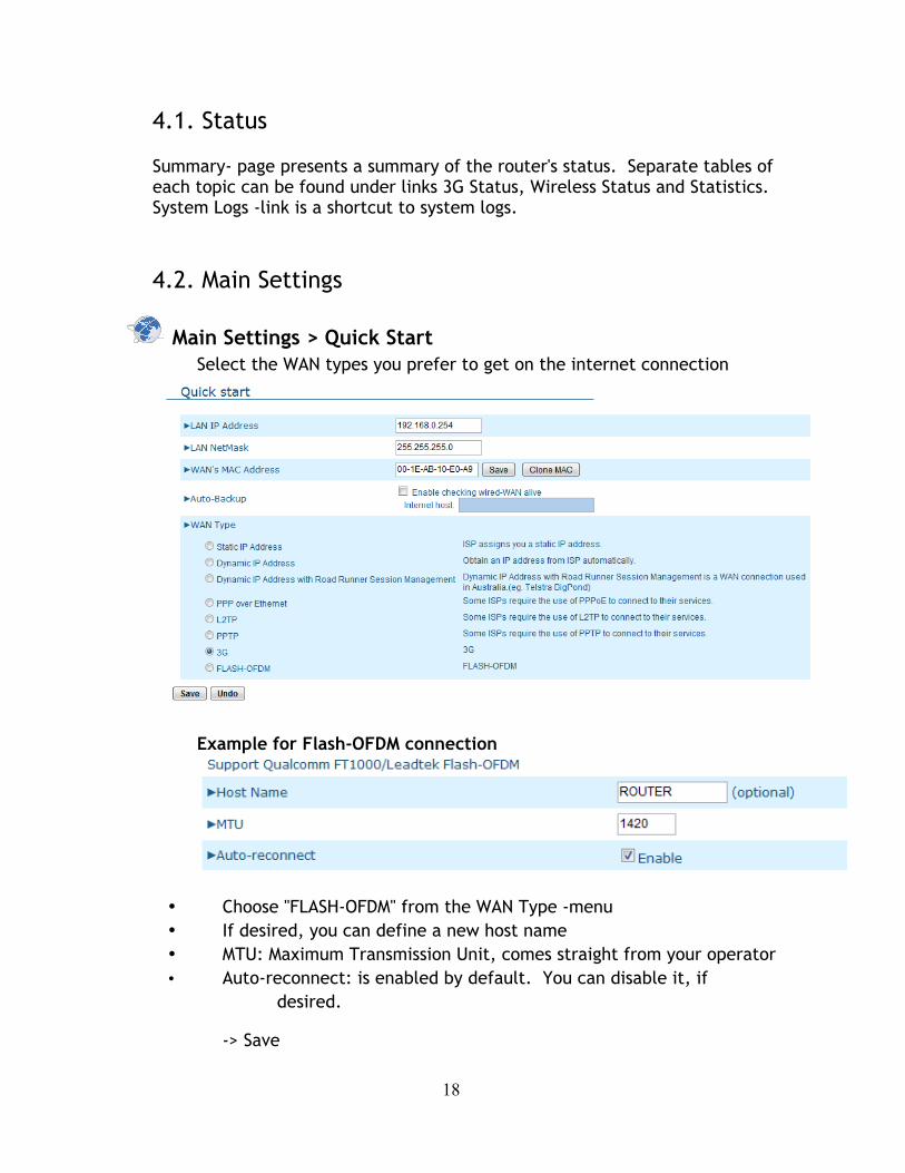
4.1. Status
Summary- page presents a summary of the router's status. Separate tables of each topic can be found under links 3G Status, Wireless Status and Statistics. System Logs -link is a shortcut to system logs. 4.2. Main Settings
Main Settings > Quick Start Select the WAN types you prefer to get on the internet connection
Example for Flash-OFDM connection
• Choose "FLASH-OFDM" from the WAN Type -menu • If desired, you can define a new host name • MTU: Maximum Transmission Unit, comes straight from your operator • Auto-reconnect: is enabled by default. You can disable it, if
desired.
-> Save
19
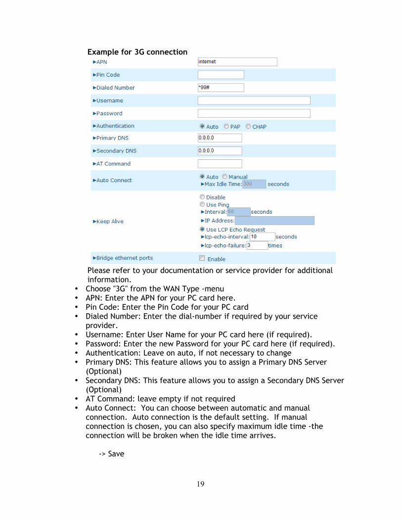
Example for 3G connection
Please refer to your documentation or service provider for additional information.
• Choose "3G" from the WAN Type -menu • APN: Enter the APN for your PC card here. • Pin Code: Enter the Pin Code for your PC card • Dialed Number: Enter the dial-number if required by your service
provider. • Username: Enter User Name for your PC card here (if required). • Password: Enter the new Password for your PC card here (if required). • Authentication: Leave on auto, if not necessary to change • Primary DNS: This feature allows you to assign a Primary DNS Server
(Optional) • Secondary DNS: This feature allows you to assign a Secondary DNS Server
(Optional) • AT Command: leave empty if not required • Auto Connect: You can choose between automatic and manual
connection. Auto connection is the default setting. If manual connection is chosen, you can also specify maximum idle time -the connection will be broken when the idle time arrives.
-> Save
20
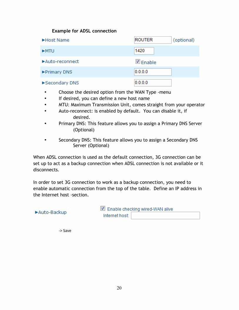
Example for ADSL connection
• Choose the desired option from the WAN Type -menu • If desired, you can define a new host name • MTU: Maximum Transmission Unit, comes straight from your operator • Auto-reconnect: is enabled by default. You can disable it, if
desired. • Primary DNS: This feature allows you to assign a Primary DNS Server
(Optional)
• Secondary DNS: This feature allows you to assign a Secondary DNS Server (Optional)
When ADSL connection is used as the default connection, 3G connection can be set up to act as a backup connection when ADSL connection is not available or it disconnects. In order to set 3G connection to work as a backup connection, you need to enable automatic connection from the top of the table. Define an IP address in the Internet host -section.
-‐> Save
21
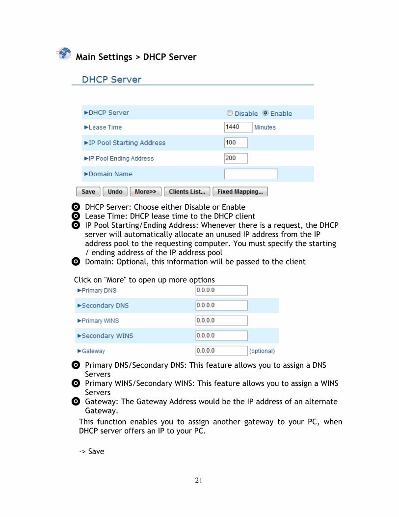
Main Settings > DHCP Server
• DHCP Server: Choose either Disable or Enable • Lease Time: DHCP lease time to the DHCP client • IP Pool Starting/Ending Address: Whenever there is a request, the DHCP
server will automatically allocate an unused IP address from the IP address pool to the requesting computer. You must specify the starting / ending address of the IP address pool
• Domain: Optional, this information will be passed to the client Click on "More" to open up more options
• Primary DNS/Secondary DNS: This feature allows you to assign a DNS
Servers • Primary WINS/Secondary WINS: This feature allows you to assign a WINS
Servers • Gateway: The Gateway Address would be the IP address of an alternate
Gateway. This function enables you to assign another gateway to your PC, when DHCP server offers an IP to your PC.
-> Save
22
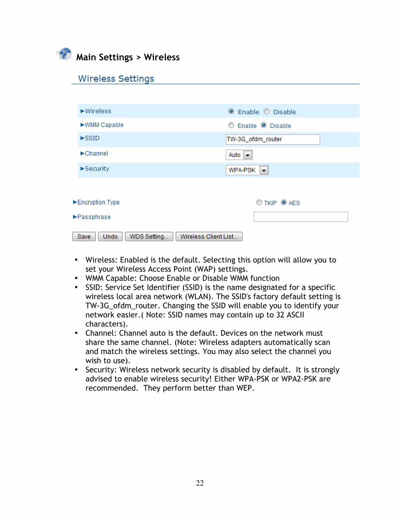
Main Settings > Wireless
• Wireless: Enabled is the default. Selecting this option will allow you to set your Wireless Access Point (WAP) settings.
• WMM Capable: Choose Enable or Disable WMM function • SSID: Service Set Identifier (SSID) is the name designated for a specific
wireless local area network (WLAN). The SSID's factory default setting is TW-3G_ofdm_router. Changing the SSID will enable you to identify your network easier.( Note: SSID names may contain up to 32 ASCII characters).
• Channel: Channel auto is the default. Devices on the network must share the same channel. (Note: Wireless adapters automatically scan and match the wireless settings. You may also select the channel you wish to use).
• Security: Wireless network security is disabled by default. It is strongly advised to enable wireless security! Either WPA-PSK or WPA2-PSK are recommended. They perform better than WEP.
23
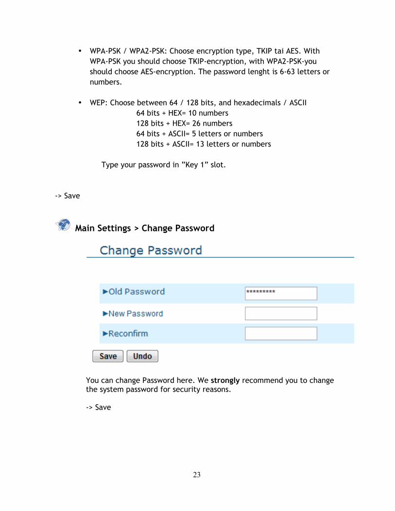
• WPA-PSK / WPA2-PSK: Choose encryption type, TKIP tai AES. With WPA-PSK you should choose TKIP-encryption, with WPA2-PSK-you should choose AES-encryption. The password lenght is 6-63 letters or numbers.
• WEP: Choose between 64 / 128 bits, and hexadecimals / ASCII 64 bits + HEX= 10 numbers 128 bits + HEX= 26 numbers 64 bits + ASCII= 5 letters or numbers 128 bits + ASCII= 13 letters or numbers
Type your password in ”Key 1” slot.
-> Save
Main Settings > Change Password
You can change Password here. We strongly recommend you to change the system password for security reasons.
-> Save

24
4.3. Forwarding Rules
Forwarding Rules > Virtual Server
This product’s NAT firewall filters out unrecognized packets to protect your Intranet, so all hosts behind this product are invisible to the outside world. If you wish, you can make some of them accessible by enabling the Virtual Server Mapping. A virtual server is defined as a Service Port, and all requests to this port will be redirected to the computer specified by the Server IP. Virtual Server can work with Scheduling Rules, and give user more flexibility on Access control. For Details, please refer to Scheduling Rule. For example, if you have an FTP server (port 21) at 192.168.123.1, a Web server (port 80) at 192.168.123.2, and a VPN server at 192.168.123.6, then you need to specify the following virtual server mapping table:
-> Save
25
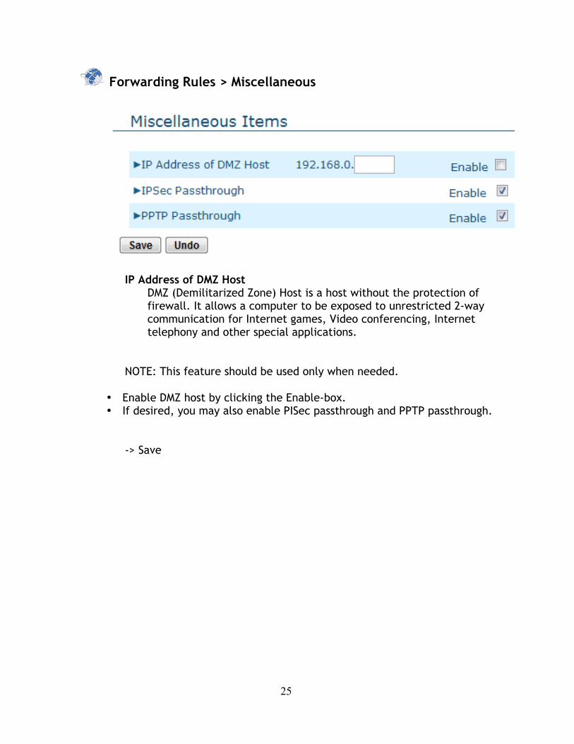
Forwarding Rules > Miscellaneous
IP Address of DMZ Host DMZ (Demilitarized Zone) Host is a host without the protection of firewall. It allows a computer to be exposed to unrestricted 2-way communication for Internet games, Video conferencing, Internet telephony and other special applications.
NOTE: This feature should be used only when needed.
• Enable DMZ host by clicking the Enable-box. • If desired, you may also enable PISec passthrough and PPTP passthrough.
-> Save

26
4.4 Security Settings
Security Settings > Packet filters
Packet Filter enables you to control what packets are allowed to pass the router. Outbound filter applies on all outbound packets. However, inbound filter applies on packets that destined to Virtual Servers or DMZ host only. You can select one of the two filtering policies:
1. Allow all to pass except those match the specified rules 2. Deny all to pass except those match the specified rules
27
You can specify 8 rules for each direction: inbound or outbound. For each rule, you can define the following:
• Source IP address • Source port • Destination IP address • Destination port • Protocol: TCP or UDP or both. • Use Rule#
For source or destination IP address, you can define a single IP address (4.3.2.1) or a range of IP addresses (4.3.2.1-4.3.2.254). An empty implies all IP addresses. For source or destination port, you can define a single port (80) or a range of ports (1000-1999). Add prefix "T" or "U" to specify TCP or UDP protocol. For example, T80, U53, U2000-2999, No prefix indicates both TCP and UDP are defined. An empty implies all port addresses. Packet Filter can work with Scheduling Rules, and give user more flexibility on Access control. For Detail, please refer to Scheduling Rule. Each rule can be enabled or disabled individually. -> Save
Inbound Filter: To enable Inbound Packet Filter click the check box next to Enable in the Inbound Packet Filter field -> Save

28
Security Settings > Domain Filters
• Domain Filter: let you prevent users under this device from accessing specific URLs.
• Domain Filter Enable: Check if you want to enable Domain Filter. • Log DNS Query: Check if you want to log the action when someone accesses the
specific URLs. • Privilege IP Address Range: Setting a group of hosts and privilege these hosts to
access network without restriction. • Domain Suffix: A suffix of URL to be restricted; For example, ".com",
"xxx.com". Action: When someone is accessing the URL met the domain-suffix, what kind of action you want. Check drop to block the access. Check log to log these access.
• Enable: Check to enable each rule.
-> Save
29
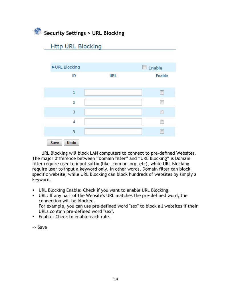
Security Settings > URL Blocking
URL Blocking will block LAN computers to connect to pre-defined Websites.
The major difference between “Domain filter” and “URL Blocking” is Domain filter require user to input suffix (like .com or .org, etc), while URL Blocking require user to input a keyword only. In other words, Domain filter can block specific website, while URL Blocking can block hundreds of websites by simply a keyword.
• URL Blocking Enable: Check if you want to enable URL Blocking. • URL: If any part of the Website's URL matches the pre-defined word, the
connection will be blocked. For example, you can use pre-defined word "sex" to block all websites if their URLs contain pre-defined word "sex".
• Enable: Check to enable each rule. -> Save
30
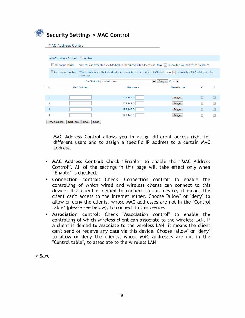
Security Settings > MAC Control
MAC Address Control allows you to assign different access right for different users and to assign a specific IP address to a certain MAC address.
• MAC Address Control: Check “Enable” to enable the “MAC Address Control”. All of the settings in this page will take effect only when “Enable” is checked.
• Connection control: Check "Connection control" to enable the controlling of which wired and wireless clients can connect to this device. If a client is denied to connect to this device, it means the client can't access to the Internet either. Choose "allow" or "deny" to allow or deny the clients, whose MAC addresses are not in the "Control table" (please see below), to connect to this device.
• Association control: Check "Association control" to enable the controlling of which wireless client can associate to the wireless LAN. If a client is denied to associate to the wireless LAN, it means the client can't send or receive any data via this device. Choose "allow" or "deny" to allow or deny the clients, whose MAC addresses are not in the "Control table", to associate to the wireless LAN
-> Save
31
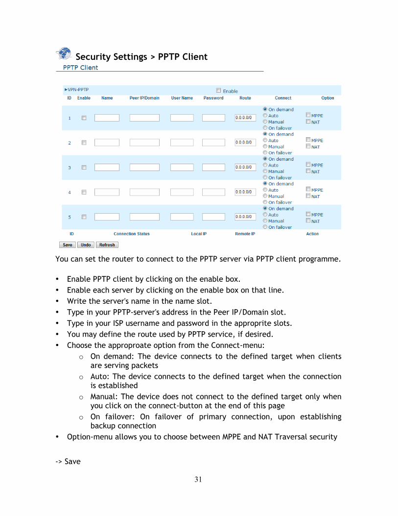
Security Settings > PPTP Client
You can set the router to connect to the PPTP server via PPTP client programme. • Enable PPTP client by clicking on the enable box. • Enable each server by clicking on the enable box on that line. • Write the server's name in the name slot. • Type in your PPTP-server's address in the Peer IP/Domain slot. • Type in your ISP username and password in the approprite slots. • You may define the route used by PPTP service, if desired. • Choose the approproate option from the Connect-menu:
o On demand: The device connects to the defined target when clients are serving packets
o Auto: The device connects to the defined target when the connection is established
o Manual: The device does not connect to the defined target only when you click on the connect-button at the end of this page
o On failover: On failover of primary connection, upon establishing backup connection
• Option-menu allows you to choose between MPPE and NAT Traversal security
-> Save
32
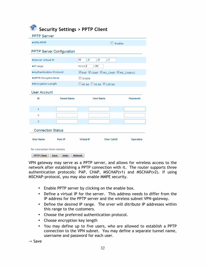
Security Settings > PPTP Client
VPN gateway may serve as a PPTP server, and allows for wireless access to the network after establishing a PPTP connection with it. The router supports three authentication protocols: PAP, CHAP, MSCHAP(v1) and MSCHAP(v2). If using MSCHAP-protocol, you may also enable MMPE security.
• Enable PPTP server by clicking on the enable box. • Define a virtual IP for the server. This address needs to differ from the
IP address for the PPTP server and the wireless subnet VPN-gateway. • Define the desired IP range. The srver will ditribute IP addresses within
this range to the customers. • Choose the preferred authentication protocol. • Choose encryption key length • You may define up to five users, who are allowed to establish a PPTP
connection to the VPN subnet. You may define a separate tunnel name, username and password for each user.
-> Save
33
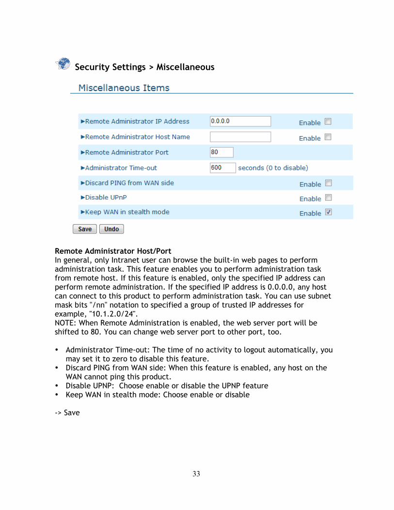
Security Settings > Miscellaneous
Remote Administrator Host/Port In general, only Intranet user can browse the built-in web pages to perform administration task. This feature enables you to perform administration task from remote host. If this feature is enabled, only the specified IP address can perform remote administration. If the specified IP address is 0.0.0.0, any host can connect to this product to perform administration task. You can use subnet mask bits "/nn" notation to specified a group of trusted IP addresses for example, "10.1.2.0/24". NOTE: When Remote Administration is enabled, the web server port will be shifted to 80. You can change web server port to other port, too.
• Administrator Time-out: The time of no activity to logout automatically, you
may set it to zero to disable this feature. • Discard PING from WAN side: When this feature is enabled, any host on the
WAN cannot ping this product. • Disable UPNP: Choose enable or disable the UPNP feature • Keep WAN in stealth mode: Choose enable or disable -> Save
34
4.5 Advanced Settings
Advanced Settings > System Log
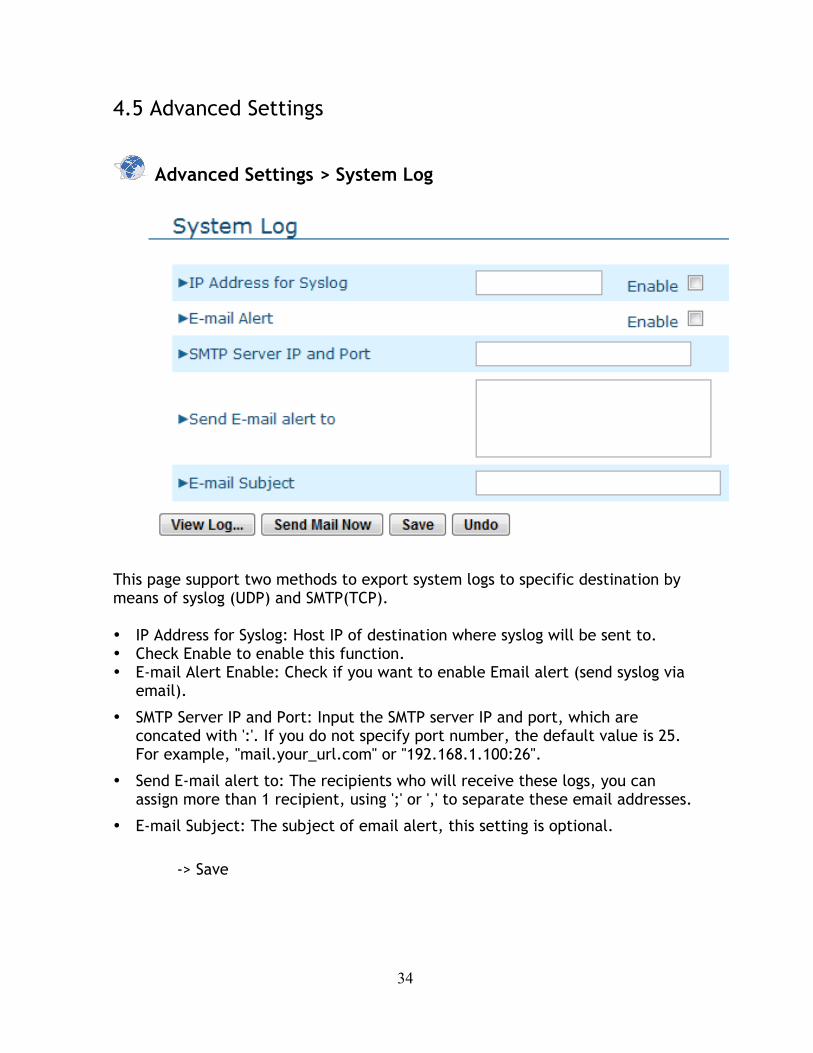
This page support two methods to export system logs to specific destination by means of syslog (UDP) and SMTP(TCP).
• IP Address for Syslog: Host IP of destination where syslog will be sent to. • Check Enable to enable this function. • E-mail Alert Enable: Check if you want to enable Email alert (send syslog via
email).
• SMTP Server IP and Port: Input the SMTP server IP and port, which are concated with ':'. If you do not specify port number, the default value is 25. For example, "mail.your_url.com" or "192.168.1.100:26".
• Send E-mail alert to: The recipients who will receive these logs, you can assign more than 1 recipient, using ';' or ',' to separate these email addresses.
• E-mail Subject: The subject of email alert, this setting is optional.
-> Save

35
Advanced Settings > Dynamic DNS
To host your server on a changing IP address, you have to use dynamic domain name service (DDNS).
So that anyone wishing to reach your host only needs to know the name of it. Dynamic DNS will map the name of your host to your current IP address, which changes each time you connect your Internet service provider.
Before you enable Dynamic DNS, you need to register an account on one of these Dynamic DNS servers that we list in provider field.
To enable Dynamic DNS click the check box next to Enable in the DDNS field.
Next you can enter the appropriate information about your Dynamic DNS Server.
You have to define:
• Provider • Host Name • Username/E-mail • Password/Key
You will get this information when you register an account on a Dynamic DNS server.
-> Save

36
Advanced Settings > QoS
QoS feature allows you to set priorities to different IP addresses, and thus limit their speed.
• Enable QoS by clicking on the enable box • Define preferred upstream and downstream bandwidth speed. This can not
be defined as 0. • You may either define a specific IP address (4.3.2.1) or a range of IP
addresses (4.3.2.1-4.3.2.254) as local and remote IP. Empty slot refers to all IP addresses.
• Similarly you may define either one specific port (80) or a range of ports (1000-1999). Empty slot refers to all ports.
• Define the desired priority to each group, and enble each rule by clicking on the enable box on the same line.
-> Save
37
Advanced Settings > SNMP
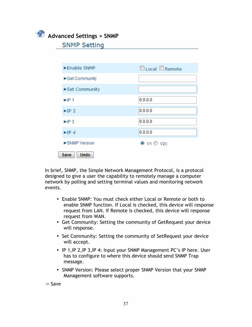
In brief, SNMP, the Simple Network Management Protocol, is a protocol designed to give a user the capability to remotely manage a computer network by polling and setting terminal values and monitoring network events.
• Enable SNMP: You must check either Local or Remote or both to enable SNMP function. If Local is checked, this device will response request from LAN. If Remote is checked, this device will response request from WAN.
• Get Community: Setting the community of GetRequest your device will response.
• Set Community: Setting the community of SetRequest your device will accept.
• IP 1,IP 2,IP 3,IP 4: Input your SNMP Management PC’s IP here. User has to configure to where this device should send SNMP Trap message.
• SNMP Version: Please select proper SNMP Version that your SNMP Management software supports.
-> Save
38
Advanced Settings > Routing
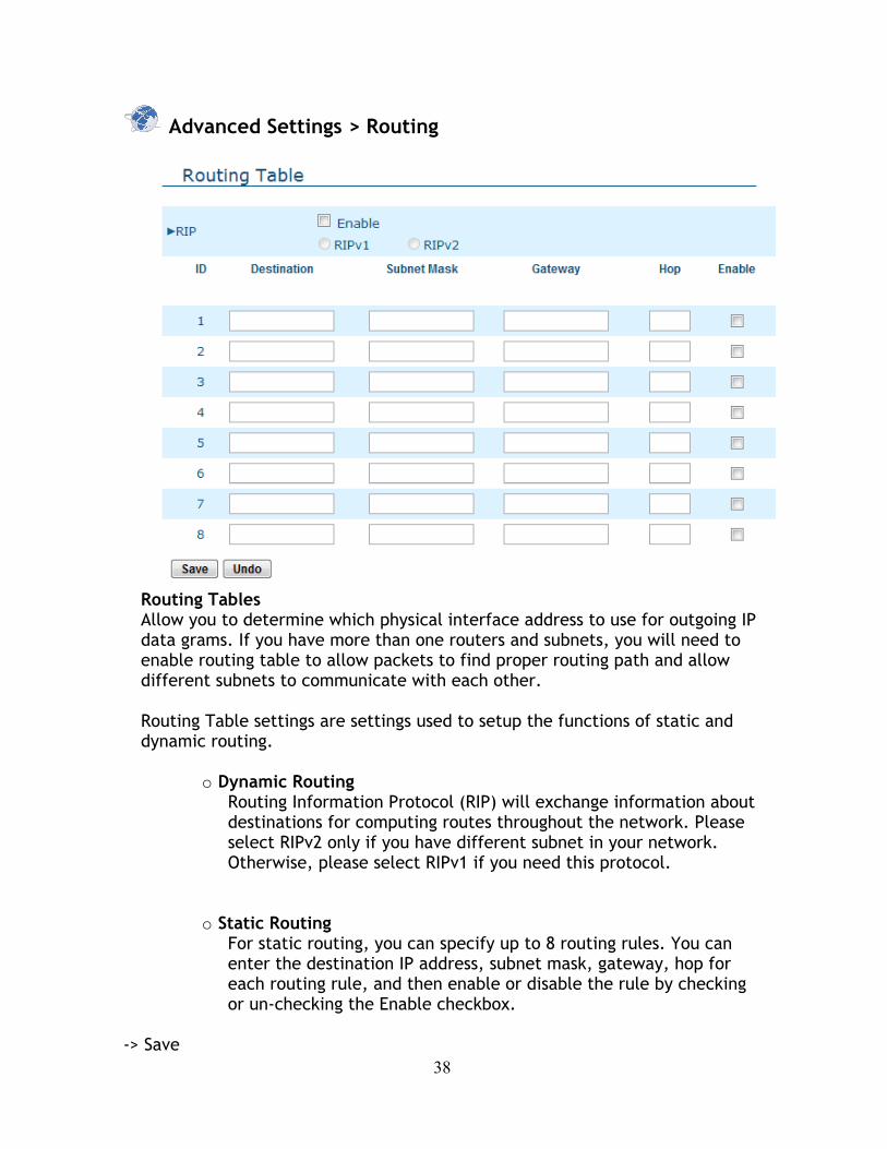
Routing Tables Allow you to determine which physical interface address to use for outgoing IP data grams. If you have more than one routers and subnets, you will need to enable routing table to allow packets to find proper routing path and allow different subnets to communicate with each other.
Routing Table settings are settings used to setup the functions of static and dynamic routing.
o Dynamic Routing Routing Information Protocol (RIP) will exchange information about destinations for computing routes throughout the network. Please select RIPv2 only if you have different subnet in your network. Otherwise, please select RIPv1 if you need this protocol.
o Static Routing For static routing, you can specify up to 8 routing rules. You can enter the destination IP address, subnet mask, gateway, hop for each routing rule, and then enable or disable the rule by checking or un-checking the Enable checkbox.
-> Save
39
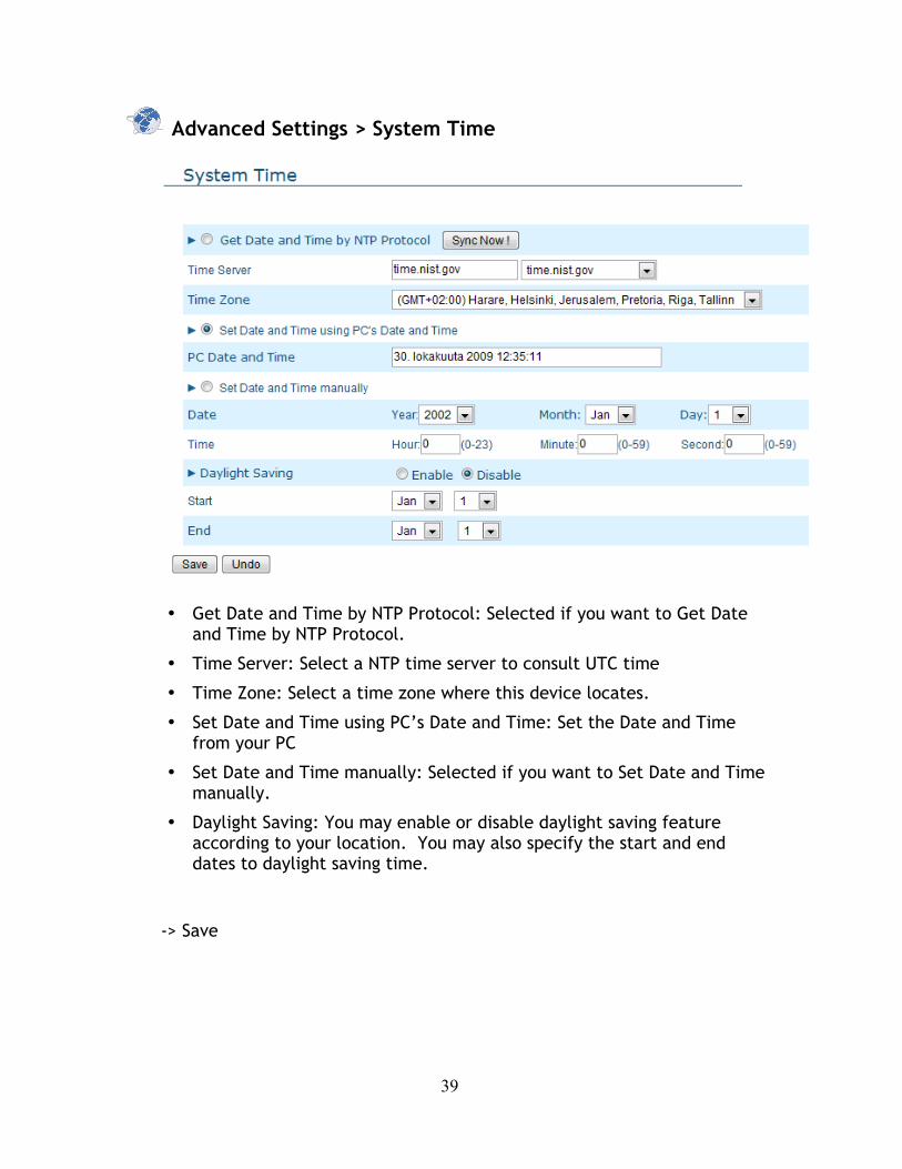
Advanced Settings > System Time
• Get Date and Time by NTP Protocol: Selected if you want to Get Date
and Time by NTP Protocol.
• Time Server: Select a NTP time server to consult UTC time
• Time Zone: Select a time zone where this device locates.
• Set Date and Time using PC’s Date and Time: Set the Date and Time from your PC
• Set Date and Time manually: Selected if you want to Set Date and Time manually.
• Daylight Saving: You may enable or disable daylight saving feature according to your location. You may also specify the start and end dates to daylight saving time.
-> Save

40
Advanced Settings > Scheduling
You can set the schedule time to decide which service will be turned on or off. Select the “enable” item. Press “Add New Rule”
You can write a rule name and set which day and what time to schedule from “Start Time” to “End Time”. The following example configure “ftp time” as everyday 14:10 to 16:20
-> Save
41
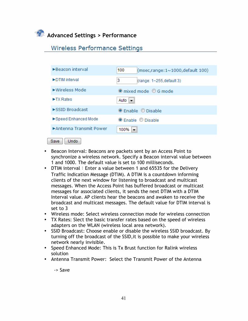
Advanced Settings > Performance
• Beacon Interval: Beacons are packets sent by an Access Point to
synchronize a wireless network. Specify a Beacon interval value between 1 and 1000. The default value is set to 100 milliseconds.
• DTIM interval:Enter a value between 1 and 65535 for the Delivery Traffic Indication Message (DTIM). A DTIM is a countdown informing clients of the next window for listening to broadcast and multicast messages. When the Access Point has buffered broadcast or multicast messages for associated clients, it sends the next DTIM with a DTIM Interval value. AP clients hear the beacons and awaken to receive the broadcast and multicast messages. The default value for DTIM interval is set to 3
• Wireless mode: Select wireless connection mode for wireless connection • TX Rates: Slect the basic transfer rates based on the speed of wireless
adapters on the WLAN (wireless local area network). • SSID Broadcast: Choose enable or disable the wireless SSID broadcast. By
turning off the broadcast of the SSID,it is possible to make your wireless network nearly invisible.
• Speed Enhanced Mode: This is Tx Brust function for Ralink wireless solution
• Antenna Transmit Power: Select the Transmit Power of the Antenna
-> Save

42
4.6 Tools
Tools > System Info
You can view the System log and Routing Table information in this page. If desired, you may also empty the system log by clicking on clear-button.
Tools > Firmware Upgrade
43
Newest firmware upgrade files can be found on out web page http://www.telewell.fi. Save the file on your computer, and then search for it on this page. Clicking on the upgrade button will update your firmware. You may also upload a previously saved settings file in the same way.
Tools > Backup Setting You can backup your settings by clicking the Backup Setting button and save it as a bin file. Once you want to restore these settings, please click Firmware Upgrade button and use the bin file you saved
Tools > Reset to Default You can also reset this product to factory default by clicking the Reset to default button. Note: The reset button in the device should not be tampered without permission from Telewell!
Tools > Reboot You can also reboot this product by clicking the Reboot button
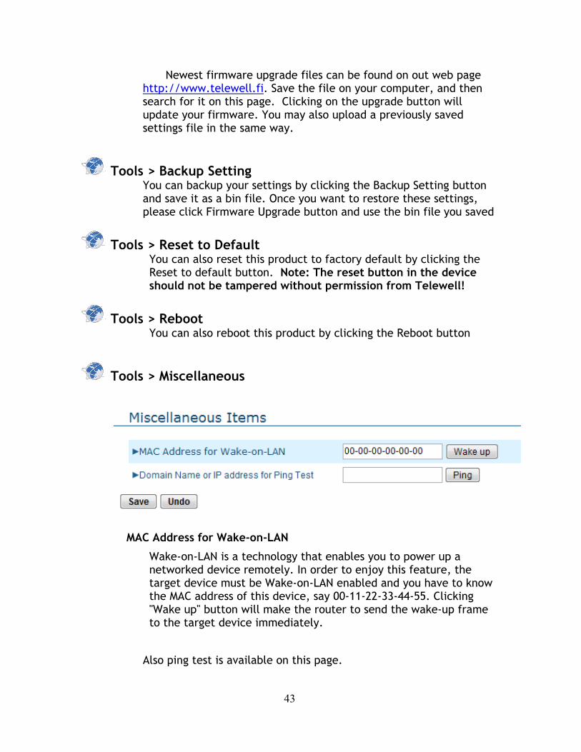
Tools > Miscellaneous
MAC Address for Wake-on-LAN
Wake-on-LAN is a technology that enables you to power up a networked device remotely. In order to enjoy this feature, the target device must be Wake-on-LAN enabled and you have to know the MAC address of this device, say 00-11-22-33-44-55. Clicking "Wake up" button will make the router to send the wake-up frame to the target device immediately.
Also ping test is available on this page.

44