Embed Size (px)
Citation preview
1
Abstract—A twin polar imetr ic configuration based on the
Faraday effect for the measurement of electr ic currents in high voltage environments is presented. Field test results are shown that indicate the device suitabili ty for current metering and relaying applications.
Index Terms — Current measurement; Magnetooptic trans-
ducers.
I. INTRODUCTION
easuring electrical currents in high voltage environments using conventional current transformers (CT) is usually
an issue that involves a great deal of insulation. Practical solutions are often costly and bulky. The use of optical technology in this field greatly reduces the need for insulation considering its intrinsic dielectric characteristics. Most of the optical sensors used for measuring electrical currents are, in fact, magnetic field sensors based on the magneto-optic Faraday effect, i.e., the induction of circular birefringence in the medium by a magnetic field H that causes linear polarized light to rotate its plane of vibration by an angle,
�,
proportional to the current under measurement[1-3]:
� � � � �� � � (1)
where V is the Verdet constant of the optical material and L the interaction length.
Among the several possible configurations, all-fiber, hybrid and bulk optics, the latest group has the highest market penetration. Bulk magneto-optic sensors can have either a closed loop configuration or a simple magnetic probe design. The sensor developed by the Optoelectronics and Electronics Systems Unit of INESC Porto, belongs to this last category.
II . PROPOSED CONFIGURATION
The proposed configuration consists of a twin all-optical
This work was per formed in the framework of project HIPOWER
(Agência Inovação S.A./PRAXIS/P014-P31B-09/96). The field tests where coordinated by EFACEC ENERGIA, the industr ial company leader of the project consor tium. a. Unidade de Optoelectrónica e Sistemas Electrónicos do INESC Porto, Rua
do Campo Alegre, 697. 4169–007 Porto, Portugal. ([email protected]). b. Dept. de Física. Faculdade de Ciências da Universidade de Porto, Rua do
Campo Alegre, 697. 4169–007 Porto. c. Dept. Sciences & Technology, University Fernando Pessoa, Pr. 9 Abril 349,
4292-004 Porto, Portugal (e-mail: [email protected]; [email protected])
magnetic probe with the two arms disposed symmetrically around the current line.
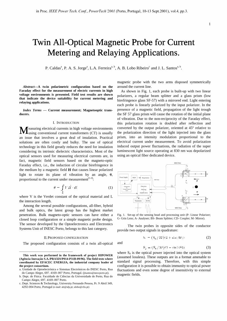
As shown in Fig. 1, each probe is built-up with two linear polarizers, a regular beam splitter and a glass prism (low birefringence glass SF-57) with a mirrored end. Light entering each probe is linearly polarized by the input polarizer. In the presence of a magnetic field, propagation of the light trough the SF 57 glass prism will cause the rotation of the initial plane of vibration. Due to the non-reciprocity of the Faraday effect, this polarization rotation is doubled after reflection and converted by the output polarizer, oriented at 45º relative to the polarization direction of the light injected into the glass prism, into an intensity modulation proportional to the electrical current under measurement. To avoid polarization induced output power fluctuations, the radiation of the super luminescent light source operating at 830 nm was depolarized using an optical fiber dedicated device.
I1
SLD Despolarizer
Detection+
Fil tering+
Ampli fication
Temperature&
Current ControlSLD
Power Supply
I
H
H
2I
I 0 1
I 0 2
MG
P
GA
B S
G
P
M
GA
CD
B S
Transients 50 Hz
A B
MM Fibre
MM Fibre
SM Fibre
Fig. 1. Set-up of the sensing head and processing unit (P- Linear Polarizer; G- Grin Lens; A- Analyser; BS- Beam Splitter; CD- Coupler; M- Mirror).
The twin probes in opposite sides of the conductor provide two output signals in quadrature:
� � �� ���� � � � � � � � � � �� � (2)
and � ! "# $%&' ' ( ) * + , - . / 01 2 (3)
where S0 is the optical power injected into the optical system (assumed lossless). These outputs are in a format amenable to standard signal processing. Therefore, with this simple configuration it is possible to obtain immunity to optical power fluctuations and even some degree of insensitivity to external magnetic fields.
Twin All-Optical Magnetic Probe for Current Metering and Relaying Applications.
P. Caldasa, P. A. S. Jorgea, L.A. Ferreiraa, b, A. B. Lobo Ribeiroc and J. L. Santosa, b.
M
2
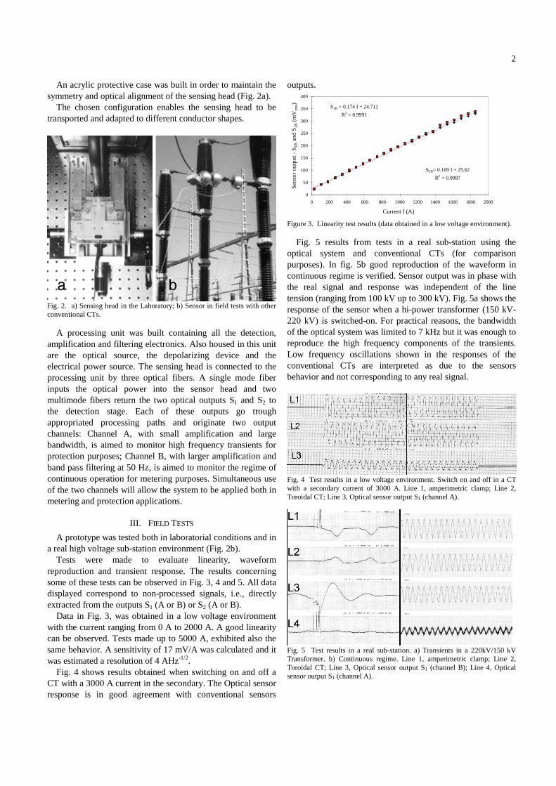
An acrylic protective case was built in order to maintain the symmetry and optical alignment of the sensing head (Fig. 2a).
The chosen configuration enables the sensing head to be transported and adapted to different conductor shapes.
Fig. 2. a) Sensing head in the Laboratory; b) Sensor in field tests with other conventional CTs.
A processing unit was built containing all the detection, amplification and filtering electronics. Also housed in this unit are the optical source, the depolarizing device and the electrical power source. The sensing head is connected to the processing unit by three optical fibers. A single mode fiber inputs the optical power into the sensor head and two multimode fibers return the two optical outputs S1 and S2 to the detection stage. Each of these outputs go trough appropriated processing paths and originate two output channels: Channel A, with small amplification and large bandwidth, is aimed to monitor high frequency transients for protection purposes; Channel B, with larger amplification and band pass filtering at 50 Hz, is aimed to monitor the regime of continuous operation for metering purposes. Simultaneous use of the two channels will allow the system to be applied both in metering and protection applications.
II I. FIELD TESTS
A prototype was tested both in laboratorial conditions and in a real high voltage sub-station environment (Fig. 2b).
Tests were made to evaluate linearity, waveform reproduction and transient response. The results concerning some of these tests can be observed in Fig. 3, 4 and 5. All data displayed correspond to non-processed signals, i.e., directly extracted from the outputs S1 (A or B) or S2 (A or B).
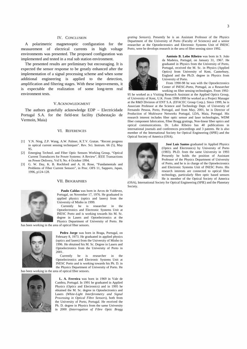
Data in Fig. 3, was obtained in a low voltage environment with the current ranging from 0 A to 2000 A. A good linearity can be observed. Tests made up to 5000 A, exhibited also the same behavior. A sensitivity of 17 mV/A was calculated and it was estimated a resolution of 4 AHz-1/2.
Fig. 4 shows results obtained when switching on and off a CT with a 3000 A current in the secondary. The Optical sensor response is in good agreement with conventional sensors
outputs.
S1B = 0.174 I + 24.711
R2 = 0.9991
S2B= 0.169 I + 25.62
R2 = 0.9987
0
50
100
150
200
250
300
350
400
0 200 400 600 800 1000 1200 1400 1600 1800 2000
Current I (A)
Se
nso
r o
utp
ut
- S 1B
and
S 2B (
mV
rms)
Figure 3. Linearity test results (data obtained in a low voltage environment).
Fig. 5 results from tests in a real sub-station using the optical system and conventional CTs (for comparison purposes). In fig. 5b good reproduction of the waveform in continuous regime is verified. Sensor output was in phase with the real signal and response was independent of the line tension (ranging from 100 kV up to 300 kV). Fig. 5a shows the response of the sensor when a hi-power transformer (150 kV-220 kV) is switched-on. For practical reasons, the bandwidth of the optical system was limited to 7 kHz but it was enough to reproduce the high frequency components of the transients. Low frequency oscil lations shown in the responses of the conventional CTs are interpreted as due to the sensors behavior and not corresponding to any real signal.
Fig. 4 Test results in a low voltage environment. Switch on and off in a CT with a secondary current of 3000 A. Line 1, amperimetric clamp; Line 2, Toroidal CT; Line 3, Optical sensor output S1 (channel A).
Fig. 5 Test results in a real sub-station. a) Transients in a 220kV/150 kV Transformer. b) Continuous regime. Line 1, amperimetric clamp; Line 2, Toroidal CT; Line 3, Optical sensor output S1 (channel B); Line 4, Optical sensor output S1 (channel A).
3
IV. CONCLUSION
A polarimetric magnetooptic configuration for the measurement of electrical currents in high voltage environments was presented. The proposed configuration was implemented and tested in a real sub station environment.
The presented results are preliminary but encouraging. It is expected the sensor response to be greatly enhanced after the implementation of a signal processing scheme and when some additional engineering is applied to the detection, amplification and filtering stages. With these improvements, it is expectable the realization of some long-term real environment tests.
V. ACKNOWLEDGMENT
The authors gratefully acknowledge EDP – Electricidade Portugal S.A. for the field-test facility (Subestação de Vermoin, Maia)
VI. REFERENCES
[1] Y.N. Ning, Z.P. Wang, A.W. Palmer, K.T.V. Gratan. “Recent progress
in optical current sensing techniques” . Rev. Sci. Instrum. 66 (5), May 95.
[2] Emerging Technol. and Fiber Optic Sensors Working Group, “Optical Current Transducers for Power Systems: A Review” , IEEE Transactions on Power Delivery, Vol 9, No. 4 October 1994.
[3] G. W. Day, K. B. Rochford and A. H. Rose, “Fundamentals and Problems of Fiber Current Sensors” , in Proc. OFS 11, Sapporo, Japan, 1996, p124-128.
VII. BIOGRAPHIES
Paulo Caldas was born in Arcos de Valdevez,
Portugal, on November 17, 1976. He graduated in applied physics (optics and lasers) from the University of Minho in 1999.
Currently he is researcher in the Optoelectronics and Electronic Systems Unit at INESC Porto and is working towards his M. Sc. degree in Lasers and Optoelectronics at the Physics Department of University of Porto. He
has been working in the area of optical fiber sensors.
Pedro Jorge was born in Braga, Portugal, on February 8, 1973. He graduated in applied physics (optics and lasers) from the University of Minho in 1996. He obtained his M. Sc. Degree in Lasers and Optoelectronics from the University of Porto in 2001.
Currently he is researcher in the Optoelectronics and Electronic Systems Unit at INESC Porto and is working towards his Ph. D. in the Physics Department of University of Porto. He
has been working in the area of optical fiber sensors. L. A. Ferre ira was born in 1969 in Vale de
Cambra, Portugal. In 1991 he graduated in Applied Physics (Optics and Electronics) and in 1995 he obtained the M. Sc. degree in Optoelectronics and Lasers (White-Light Interferometry and Signal Processing in Optical Fibre Sensors), both from the University of Porto, Portugal. He received the Ph. D. degree in Physics from the same University in 2000 (Interrogation of Fibre Optic Bragg
grating Sensors). Presently he is an Assistant Professor of the Physics Department of the University of Porto (Faculty of Sciences) and a senior researcher at the Optoelectronics and Electronic Systems Unit of INESC Porto, were he develops research in the area of f ibre sensing since 1992.
António B. Lobo Ribeiro was born in S. João
da Madeira, Portugal, on January 31, 1967. He graduated in Physics from the University of Porto, Portugal, received the M. Sc. in Physics (Applied Optics) from University of Kent, Canterbury, England and the Ph.D. degree in Physics from University of Porto.
From 1990-98 he was with the Optoelectronics Center of INESC-Porto, Portugal, as a Researcher working on fiber sensing technologies. From 1992-
95 he worked as a Visiting Research Assistant at the Applied Optics Group, of University of Kent, U.K. From 1998-1999 he worked as a Project Manager at the R&D Division of ENT S.A. (EFACEC Group Corp.). Since 1999, he is Associate Professor at the Science and Technology Dept. of University of Fernando Pessoa, Porto, Portugal, and from May, 2001, he is Director of Production of Multiwave Networks Portugal, LDA, Maia, Portugal. His research interest includes fiber optic sensor and laser technologies, WDM fiber component fabrication, Fiber Bragg gratings, Non-linear fiber optics and optical communications. Dr. Lobo Ribeiro has 40 publications in international journals and conferences proceedings and 3 patents. He is also member of the International Society for Optical Engineering (SPIE) and the Optical Society of America (OSA).
José Luís Santos graduated in Applied Physics
(Optics and Electronics) by University of Porto (1983). Ph.D. from the same University in 1993 Presently he holds the position of Assistant Professor of the Physics Department of University of Porto, and he is in charge of the Optoelectronics and Electronic Systems Unit of INESC Porto. His research interests are connected to optical fibre technology, particularly fibre optic based sensors He is member of the Optical Society of America
(OSA), International Society for Optical Engineering (SPIE) and the Planetary Society.