Embed Size (px)
Citation preview
TWIN OTTER EXTENDED
Volume 2
Systems Version 31/07/2013 10:01:59
RECORD OF REVISIONS
revision n° Issue date Release Description
1.00 06 July 2013 1.00 Online release
1.01 12 July 2013 1.01 Change in AP text
1.02 31 July 2013 1.03 Changed text about AP
Aerosoft Twin Otter EXTENDED
Systems Vol 2
2-1-1 31 July 2013
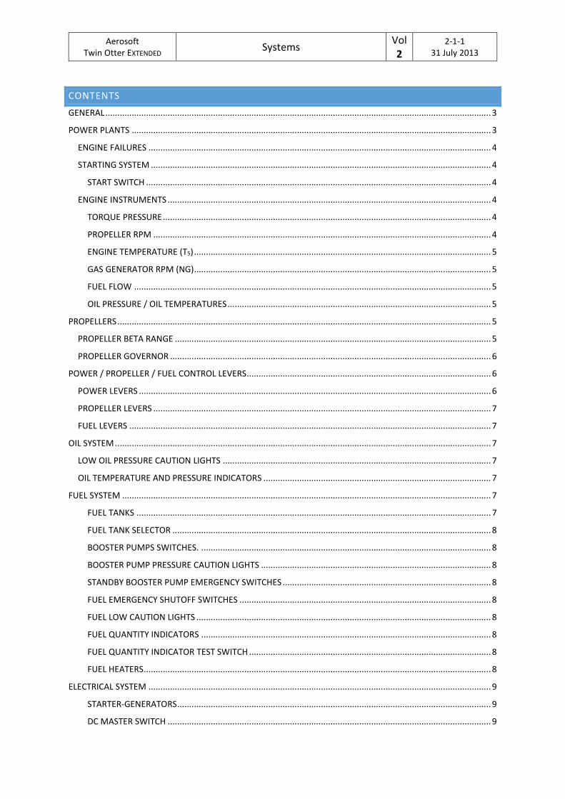
CONTENTS
GENERAL ................................................................................................................................................................. 3
POWER PLANTS ...................................................................................................................................................... 3
ENGINE FAILURES ............................................................................................................................................... 4
STARTING SYSTEM .............................................................................................................................................. 4
START SWITCH ................................................................................................................................................ 4
ENGINE INSTRUMENTS ....................................................................................................................................... 4
TORQUE PRESSURE ......................................................................................................................................... 4
PROPELLER RPM ............................................................................................................................................. 4
ENGINE TEMPERATURE (T5) ............................................................................................................................ 5
GAS GENERATOR RPM (NG)............................................................................................................................ 5
FUEL FLOW ..................................................................................................................................................... 5
OIL PRESSURE / OIL TEMPERATURES .............................................................................................................. 5
PROPELLERS ............................................................................................................................................................ 5
PROPELLER BETA RANGE .................................................................................................................................... 5
PROPELLER GOVERNOR ...................................................................................................................................... 6
POWER / PROPELLER / FUEL CONTROL LEVERS...................................................................................................... 6
POWER LEVERS ................................................................................................................................................... 6
PROPELLER LEVERS ............................................................................................................................................. 7
FUEL LEVERS ....................................................................................................................................................... 7
OIL SYSTEM ............................................................................................................................................................. 7
LOW OIL PRESSURE CAUTION LIGHTS ................................................................................................................ 7
OIL TEMPERATURE AND PRESSURE INDICATORS ............................................................................................... 7
FUEL SYSTEM .......................................................................................................................................................... 7
FUEL TANKS .................................................................................................................................................... 7
FUEL TANK SELECTOR ..................................................................................................................................... 8
BOOSTER PUMPS SWITCHES. ......................................................................................................................... 8
BOOSTER PUMP PRESSURE CAUTION LIGHTS ................................................................................................ 8
STANDBY BOOSTER PUMP EMERGENCY SWITCHES ....................................................................................... 8
FUEL EMERGENCY SHUTOFF SWITCHES ......................................................................................................... 8
FUEL LOW CAUTION LIGHTS ........................................................................................................................... 8
FUEL QUANTITY INDICATORS ......................................................................................................................... 8
FUEL QUANTITY INDICATOR TEST SWITCH ..................................................................................................... 8
FUEL HEATERS ................................................................................................................................................. 8
ELECTRICAL SYSTEM ............................................................................................................................................... 9
STARTER-GENERATORS ................................................................................................................................... 9
DC MASTER SWITCH ....................................................................................................................................... 9
Aerosoft Twin Otter EXTENDED
Systems Vol 2
2-1-2 31 July 2013
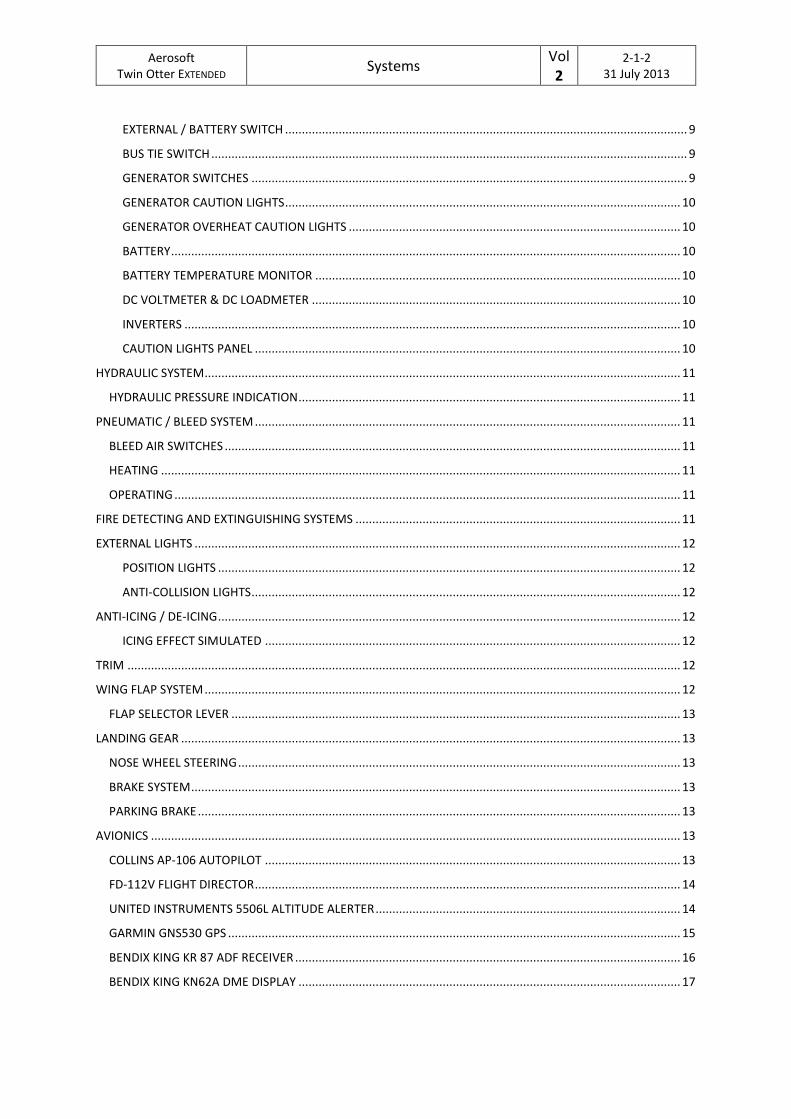
EXTERNAL / BATTERY SWITCH ........................................................................................................................ 9
BUS TIE SWITCH .............................................................................................................................................. 9
GENERATOR SWITCHES .................................................................................................................................. 9
GENERATOR CAUTION LIGHTS ...................................................................................................................... 10
GENERATOR OVERHEAT CAUTION LIGHTS ................................................................................................... 10
BATTERY ........................................................................................................................................................ 10
BATTERY TEMPERATURE MONITOR ............................................................................................................. 10
DC VOLTMETER & DC LOADMETER .............................................................................................................. 10
INVERTERS .................................................................................................................................................... 10
CAUTION LIGHTS PANEL ............................................................................................................................... 10
HYDRAULIC SYSTEM .............................................................................................................................................. 11
HYDRAULIC PRESSURE INDICATION .................................................................................................................. 11
PNEUMATIC / BLEED SYSTEM ............................................................................................................................... 11
BLEED AIR SWITCHES ........................................................................................................................................ 11
HEATING ........................................................................................................................................................... 11
OPERATING ....................................................................................................................................................... 11
FIRE DETECTING AND EXTINGUISHING SYSTEMS ................................................................................................. 11
EXTERNAL LIGHTS ................................................................................................................................................. 12
POSITION LIGHTS .......................................................................................................................................... 12
ANTI-COLLISION LIGHTS ................................................................................................................................ 12
ANTI-ICING / DE-ICING .......................................................................................................................................... 12
ICING EFFECT SIMULATED ............................................................................................................................ 12
TRIM ..................................................................................................................................................................... 12
WING FLAP SYSTEM .............................................................................................................................................. 12
FLAP SELECTOR LEVER ...................................................................................................................................... 13
LANDING GEAR ..................................................................................................................................................... 13
NOSE WHEEL STEERING .................................................................................................................................... 13
BRAKE SYSTEM .................................................................................................................................................. 13
PARKING BRAKE ................................................................................................................................................ 13
AVIONICS .............................................................................................................................................................. 13
COLLINS AP-106 AUTOPILOT ............................................................................................................................ 13
FD-112V FLIGHT DIRECTOR ............................................................................................................................... 14
UNITED INSTRUMENTS 5506L ALTITUDE ALERTER ........................................................................................... 14
GARMIN GNS530 GPS ....................................................................................................................................... 15
BENDIX KING KR 87 ADF RECEIVER ................................................................................................................... 16
BENDIX KING KN62A DME DISPLAY .................................................................................................................. 17
Aerosoft Twin Otter EXTENDED
Systems Vol 2
2-1-3 31 July 2013
GENERAL
The de Havilland DHC-6 Twin Otter was developed by de Havilland Canada as STOL aircraft. It is still produced
by Viking air. It has been successful as a cargo, passenger, firefighting and Medevac aircraft as well as being
popular for sky diving operations. The Twin Otter comes with floats, skis and tricycle landing gear as well as
amphibian versions and many are used as bush planes in remote places like Canada, Alaska, Africa, Australia
and Antarctica.
It was developed as a replacement for the single engine Otter, also made by de Havilland Canada.
Development started back in 1964 and first flight was in 1965. The Twin Otter features double slotted flaps as
well as using ailerons for STOL performance. The engines selected where the Pratt and Whitney 550 shp PT6A-
20 turboprop engines. The first version was the 100 series and later the 200 series with a longer nose and
larger baggage compartment was introduced, still using the 550 Shp PW PT6A-20 engines. In 1969 the 300
series was developed with the 620 shp PT6A-27 engines.
Production of the 300 series ended in 1988 thereafter Viking air took over production. In 2010 the first 400
series was delivered with modern avionics and use of composite in some of the structures.
POWER PLANTS
The Twin Otter airplanes are powered by wing-mounted PT6A turboprop engines constructed by Pratt and
Whitney. These light weight gas turbine feature twin independent turbines that are only aerodynamically
coupled. The first stage (compressor) drives the gas generator section while the second turbine drives the
propellers through a reduction gearbox. It might surprise you that air is actually entering the engine at the
back and exhausts at the front. Inside the engine the airflow reverses three times. Although more complex
than a straight jet engine the PT6A is highly reliable as long as temperatures are controlled. Any operation in
the beta ranges cause the engine to heat up and should be monitored.
The engines used on the Twin Otter are the Pratt & Whitney PT-6A range of free turbine turboprop engines. In
a free turbine there is a core engine called the gas producer. It works like a normal jet engine, where air is
compressed by a couple of compressor stages, then entering the combustion chambers where fuel is mixed
with the air and ignited. The air then expands due to the temperature increase and can then be used to drive a
turbine, which again is connected to the compressor section of the engine. Another turbine is then driving the
propeller via a reduction gear. Since this turbine isn´t mechanical connected to the core engine, it´s called a
free turbine.
On the PT6A the air inlet is at the rear of the engine nacelle and exhaust is in front. This way the free turbine
that drives the propeller gets closer to the gearbox and propeller. An air scoop runs at the bottom of the
nacelle and contains the inertial separator. The inertial separator includes an electrical controlled,
pneumatically operated deflector as well as a diffuser.
The deflector can be retracted or extended via a switch in the cockpit. The diffuser is a fine mesh screen
projecting into the air path at the upswept and of the engine air inlet. An exit duct door in the aft portion of
the nacelle operates in synchronisation with the deflector. When the inertial separator is extended, debris or
ice will be deflected through the exit duct, due to the inertia of the particles. With the inertial separator
extended, maximum continuous torque from the engines will be lower, due to the loss of air through the exit
door. The compressor part of the engines also supplies bleed air for cabin heating and air pressure for the de-
icing boots. Note that the "Low Pneu" warning light will be lit when engines are at idle.
Aerosoft Twin Otter EXTENDED
Systems Vol 2
2-1-4 31 July 2013
ENGINE FAILURES
The following failures are simulated:
Excessive T5 temperature: Whenever the T5 temperature gauges goes into the red area, an over
temperature situation exist. Depending on the amount of over temperature, the engines will fail after
some time.
Ice ingestion: When icing conditions exist, ice might build up near the engine air-intakes which might
break off and get ingested to the engines, thus causing a flameout. To prevent flameouts, turn on
intake heaters and extend the inertial separators.
Hot-start: Hot-starts occur if fuel is introduced before Ng (Gas-producer RPM) has reached 12%. The
combustion chambers gets flooded with fuel with insufficient airflow. You will see that T5
temperature gets very hot.
Engine over torque: Engine over torque occurs when torque is set higher than maximum allowed
continuous torque. The torque gauges has a red mark at approximately 49% for the PT6A-27. This
only marks the maximum to be reached under ISA conditions (15°C, 1013 mbar) at sea level. When
outside temperature increases or as you climb, this value will decrease. In this chart the actual
maximum allowable torque can be found: (Chart to be inserted for PT6A-27). You can also open the
checklist and look on page 1 where a blue bug indicates actually maximum torque on the torque
gauges found there. The engines will fail after a certain time as a function of over torque amount.
Failure due to over torque and over temperature will trigger an engine fire. Shut off fuel and pull the fire
handle to activate the fire extinguisher.
STARTING SYSTEM
The starting system for each engine combines a starter/generator, start switch and starter relays. With the DC
Master switch on and the starter switch held to the start position, the starter motor will rotate the gas
generator turbine. When it reaches sufficient RPM the engine will light-up. The starter switch can then be
released and the starter motor will start to function as generator..
START SWITCH
A three positioned start switch is located on the left overhead panel. The spring loaded LEFT and RIGHT
positions energize the left and right engine starter systems.
ENGINE INSTRUMENTS
TORQUE PRESSURE
The main thrust indicator as it shows the portion of total thrust to the propeller. This gauge requires 26 volts
to operate. It is your primary trust indicator as it indicates how much of the total power is delivered to the
propeller.
PROPELLER RPM
This mechanical gauge (does not require electrical power) indicates the revolution per minute of the propeller.
It indicates in percentage of maximum RPM (around 2200).
Aerosoft Twin Otter EXTENDED
Systems Vol 2
2-1-5 31 July 2013
ENGINE TEMPERATURE (T 5)
Engine temperature is measured at 8 locations in the gas stream between the gas generator turbine and the
power turbine. An average of the temperature is send to the instrument panel and the gauge requires 26 volts
to operate.
GAS GENERATOR RPM (NG)
Gas Generator RPM is measured at the accessory gear and is send to the instrument panel in percentage of
maximum design RPM.
FUEL FLOW
See Fuel System section.
OIL PRESSURE / OIL TEMPERATURES
See Oil System section.
PROPELLERS
The Twin Otter comes with either 3 bladed or a 4 bladed propellers with similar performance. The 4 bladed propellers make less noise and are therefore better suited in some conditions. The propellers are of the constant speed type, which means that blade pitch is set to keep a certain propeller RPM.
Normally when the engines are stopped, the propeller blades will feather due to loss of oil pressure. On some floatplanes there are devices called “start locks” which prevents the propeller blades from feathering. This is done to prevent any thrust to be produced during startup, which can be troublesome on floatplanes.
The Twin Otter has an auto feather system, which will automatically will feather the propeller if an engine should fail. It senses if there is too large a difference of torque between the two engines.
Below the power levers flight idle range the propellers are operated in ‘beta range’. In beta range the blades are controlled directly by the power lever and can also be set to zero pitch as well as reverse. While not certified to be used when flying, reverse power can still be applied.
During the run-up check certain functions of the auto feather and beta range controls are checked to ensure their proper function. The testing of the beta control system include the beta range backup system, which prevents the propeller blades to run into an unacceptable low pitch if the beta control system should fail. A micro switch that senses when reverse power is applied is tested during run-up.
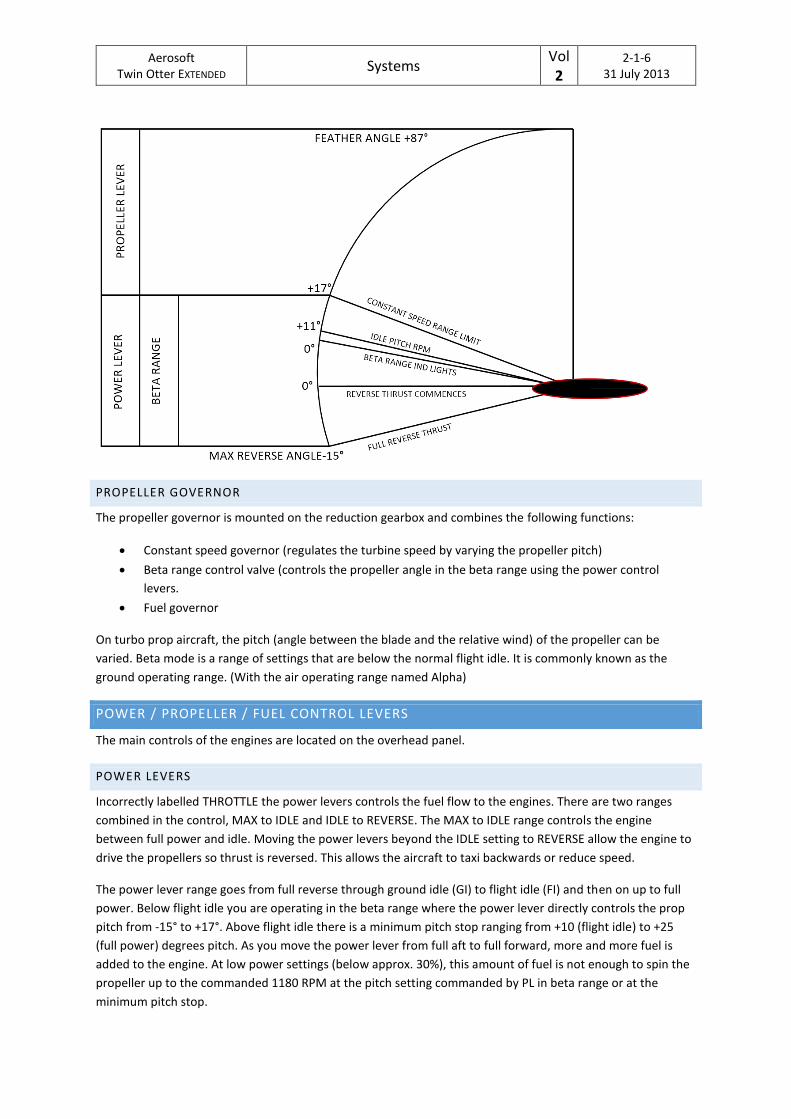
The two constant speed propellers (3 or 4 bladed) have a propeller reverse cam mechanism to control the blades between its 17° and -15° (beta) range. It features an overspeed protection, auto feathering and an optional blade latch system. The rotational speed is indicated on a propeller tachometer on the engine instrument panel
PROPELLER BETA RANGE
The propeller beta range is the pitch range that is controlled by the power levers (+17° to -15°). Propeller
speed in the beta range is controlled by the propeller governor fuel section together with the engine fuel
controllers.
Aerosoft Twin Otter EXTENDED
Systems Vol 2
2-1-6 31 July 2013
PROPELLER GOVERNOR
The propeller governor is mounted on the reduction gearbox and combines the following functions:
Constant speed governor (regulates the turbine speed by varying the propeller pitch)
Beta range control valve (controls the propeller angle in the beta range using the power control
levers.
Fuel governor
On turbo prop aircraft, the pitch (angle between the blade and the relative wind) of the propeller can be
varied. Beta mode is a range of settings that are below the normal flight idle. It is commonly known as the
ground operating range. (With the air operating range named Alpha)
POWER / PROPELLER / FUEL CONTROL LEVERS
The main controls of the engines are located on the overhead panel.
POWER LEVERS
Incorrectly labelled THROTTLE the power levers controls the fuel flow to the engines. There are two ranges
combined in the control, MAX to IDLE and IDLE to REVERSE. The MAX to IDLE range controls the engine
between full power and idle. Moving the power levers beyond the IDLE setting to REVERSE allow the engine to
drive the propellers so thrust is reversed. This allows the aircraft to taxi backwards or reduce speed.
The power lever range goes from full reverse through ground idle (GI) to flight idle (FI) and then on up to full
power. Below flight idle you are operating in the beta range where the power lever directly controls the prop
pitch from -15° to +17°. Above flight idle there is a minimum pitch stop ranging from +10 (flight idle) to +25
(full power) degrees pitch. As you move the power lever from full aft to full forward, more and more fuel is
added to the engine. At low power settings (below approx. 30%), this amount of fuel is not enough to spin the
propeller up to the commanded 1180 RPM at the pitch setting commanded by PL in beta range or at the
minimum pitch stop.
Aerosoft Twin Otter EXTENDED
Systems Vol 2
2-1-7 31 July 2013
Beta modes allows much faster control of the thrust. Due to the slow response to throttle setting changes in
turbo engines it is very impractical to use the throttle to control movement on the ground. You would have to
wait for the gas generator to spin up (Ng increase), providing more torque through the power turbine (PT)
increasing the prop RPM (Np). The prop CS governor would then tell the pitch control unit (PCU) to increase
the prop pitch and then you would get additional power. In beta mode, you change the pitch first instead using
the inertia in the propeller system to provide thrust, letting the Ng accelerate or decelerate in response to Np
to keep Np constant.
PROPELLER LEVERS
The propeller levers control the target propeller rpm that the systems will try to maintain regardless of the
power output through the propeller governor.
FUEL LEVERS
The fuel levers are basically just a fuel cut-off levers as there is no mixture on turbine engines.
OIL SYSTEM
Each engine has an integral oil system and consists of an oil tank, pump, filter and cooler. The heated oil is
used to warm up the fuel.
LOW OIL PRESSURE CAUTION LIGHTS
Two low oil pressure caution lights are located on the caution panel and will light when the pressure drops
below 40 psi and will go out when pressure reaches 44 psi.
OIL TEMPERATURE AND PRESSURE INDICATORS
On the Engine panel there are gauges for oil temperature and oil pressure.
FUEL SYSTEM
The Twin Otter has a simple and reliable fuel system but with the tanks low in the airframe and the engines
mounted high it is fully depended on booster pumps. Correct management of the booster pumps is therefore
very important.
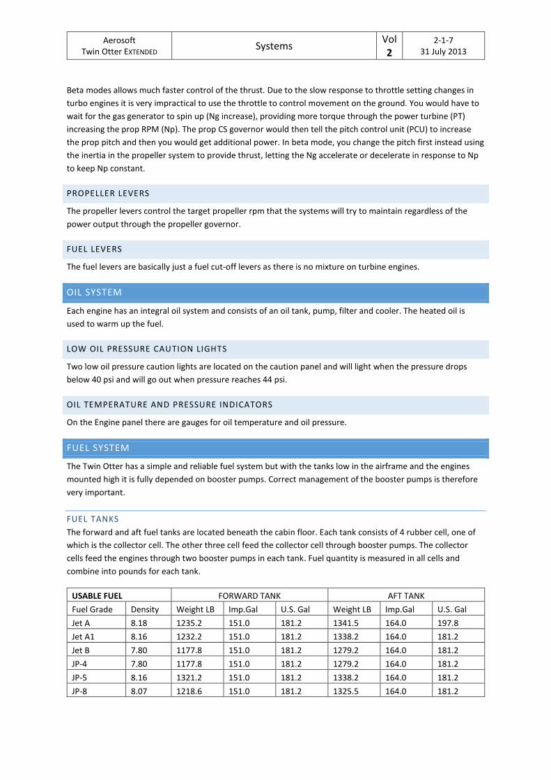
FUEL TANKS
The forward and aft fuel tanks are located beneath the cabin floor. Each tank consists of 4 rubber cell, one of
which is the collector cell. The other three cell feed the collector cell through booster pumps. The collector
cells feed the engines through two booster pumps in each tank. Fuel quantity is measured in all cells and
combine into pounds for each tank.
USABLE FUEL FORWARD TANK AFT TANK
Fuel Grade Density Weight LB Imp.Gal U.S. Gal Weight LB Imp.Gal U.S. Gal
Jet A 8.18 1235.2 151.0 181.2 1341.5 164.0 197.8
Jet A1 8.16 1232.2 151.0 181.2 1338.2 164.0 181.2
Jet B 7.80 1177.8 151.0 181.2 1279.2 164.0 181.2
JP-4 7.80 1177.8 151.0 181.2 1279.2 164.0 181.2
JP-5 8.16 1321.2 151.0 181.2 1338.2 164.0 181.2
JP-8 8.07 1218.6 151.0 181.2 1325.5 164.0 181.2
Aerosoft Twin Otter EXTENDED
Systems Vol 2
2-1-8 31 July 2013
FUEL TANK SELECTOR
In normal operation the aft tank feeds the left engine and the forward tank the right engine. Cross feed
operation is possible through a fuel selector on the overhead panel. The fuel selector rotary knob (FUEL
SELECTOR) has three settings
NORM: forward tank feeds right engine, aft tank feeds left engine, Cross feed valve is closed, No1
boost pump in each tank is energized when the respective boost pump switch is on, No2 boost pump
is deactivated.
BOTH ON FORWARD/BOTH ON AFT: cross feed valve is open, boost pumps on non-selected tank
deactivated, both booster pumps on the selected tank activated (booster pump switch overridden).
The cross feed valve is powered by the right DC bus.
BOOSTER PUMPS SWITCHES.
The two booster pump switches are located on both sides the fuel selector and control the No1 booster pump
in each tank. They have three settings
AFT BOOST/FWD BOOST: activates the pump.
OFF: deactivates the pump
TEST: momentary setting to test the system
The No2 booster pumps are activated automatic on failure of the No1 pump.
BOOSTER PUMP PRESSURE CAUTION LIGHTS
Four caution lights (BOOST PUMP 1 AFT PRESS, BOOST PUMP 2 AFT PRESS, BOOST PUMP 1 FWD PRESS, BOOST
PUMP 2 FWD PRESS) light up when the pressure downstream of the fuel line drops below 2 psi. The second
caution light of each tank is then automatically switched off. Should No1 booster pump fail its caution light will
illuminate and the No2 caution light will be put online and will illuminate should the No2 booster pump fail.
STANDBY BOOSTER PUMP EMERGENCY SWITCHES
Because the tanks of the Twin Otter are located below the engines, any gravity feed is impossible and a the
No2 booster pumps can be manually activated with these switches
FUEL EMERGENCY SHUTOFF SWITCHES
An emergency fuel shutoff switch for each engine is located on the emergency panel and control firewall
shutoff valves.
FUEL LOW CAUTION LIGHTS
Two low fuel caution lights on the caution panel will light when 75 lb (aft) and 11 lb (forward) remains. This is
only accurate in level flight!
FUEL QUANTITY INDICATORS
Two fuel quantity indicators show the remaining fuel in the aft and forward tanks in LBS x 100.
FUEL QUANTITY INDICATOR TEST SWITCH
A fuel quantity indicator test switch is located close to the fuel selector. This push button (IND TEST) will cut
power to the fuel indicators and they should fall to zero
FUEL HEATERS
Aerosoft Twin Otter EXTENDED
Systems Vol 2
2-1-9 31 July 2013
Fuel heaters are installed on each engine to prevent ice crystals being formed. The heat exchangers use
engine oil to heat the fuel. It is operated automatically by a temperature control valve.
ELECTRICAL SYSTEM
The 28-volt direct current uses two engine driven starter-generators and a 40-amp-hour battery to feed the
system. Two static inverters provide 115-volt and 26-volt alternating current. Multiple busses to power diverse
equipment:
Left (left generator): pilot’s directional gyro, pilot’s attitude indicator
Right (right generator): copilot’s directional gyro, copilot’s attitude indicator
Main Battery
Battery / External
Auxiliary battery dc bus
Two ac busses
STARTER-GENERATORS
The engine driven generators (that serve as starter motors) provide 200 amperes at 28.5 volt. They come
online when the driving engine reaches idle + 15% rpm after the generator switch is moved through RESET and
set to ON.
DC MASTER SWITCH
The two position dc master switch is located on the overhead panel.
OFF: no power to any bus except the main battery bus
DC MASTER: connects the generators, battery or external power to the left and right bus
EXTERNAL / BATTERY SWITCH
This three position is located on the overhead panel.
EXTERNAL: isolates the battery and connects external power to the left and right bus.
OFF: no connection
BATTERY: battery will power the electrical system if the generators are not running or if the generator
provided voltage is lower than the battery voltage.
BUS TIE SWITCH
The two position bus tie switch is located on the overhead panel.
NORMAL: with generators offline external power or battery to both busses, with generator running
generators output is paralleled and both busses connected. When one generator fails, both busses
are powered from the other generator
OPEN: left generator powers left bus and battery, right generator powers the right bus.
GENERATOR SWITCHES
The two (left/right) three position generator switches are located on the overhead panel.
OFF: disconnects the generator.
ON: connects the generator the bus via voltage regulator.
Aerosoft Twin Otter EXTENDED
Systems Vol 2
2-1-10 31 July 2013
RESET: when the generator drops offline (due to under voltage or over voltage) the RESET position
must be held shortly before reconnecting. Do not try to reconnect more the two times!
GENERATOR CAUTION LIGHTS
The generator caution lights on the caution panel will illuminate when the generator is offline. Left light is
powered from right bus, right light is powered from left bus.
GENERATOR OVERHEAT CAUTION LIGHTS
The generator overheat caution lights on the caution panel (optional) indicate an overheat condition. Left light
is powered from right bus, right light is powered from left bus.
BATTERY
The 40-ampere-hour nickel cadmium battery is located beneath the aft baggage compartment. An auxiliary 3.6
ampere-hour battery is used by the starting and ignition phases.
BATTERY TEMPERATURE MONITOR
The battery temperature is monitored using a temperature gauge and a caution light that will illuminate at
150°. A test button will simulate an overheat condition to test the gauge and light.
DC VOLTMETER & DC LOADMETER
The dc voltmeter is located on the front panel (next to the emergency panel) and will show the voltage of the
left /right generator and the battery depending on the switch. The loadmeter indicates the charge or discharge
of the battery or the load on the generators.
INVERTERS
Two 400 cycle, single-phase static inverters provide 115 and 26 volt. They have an approximate similar
operational use and should be alternated between flights using the two position inverter switch. The non-
active inverter is the available in case the active one fails. The 400 CYCLE caution light will indicate a failed
inverted.
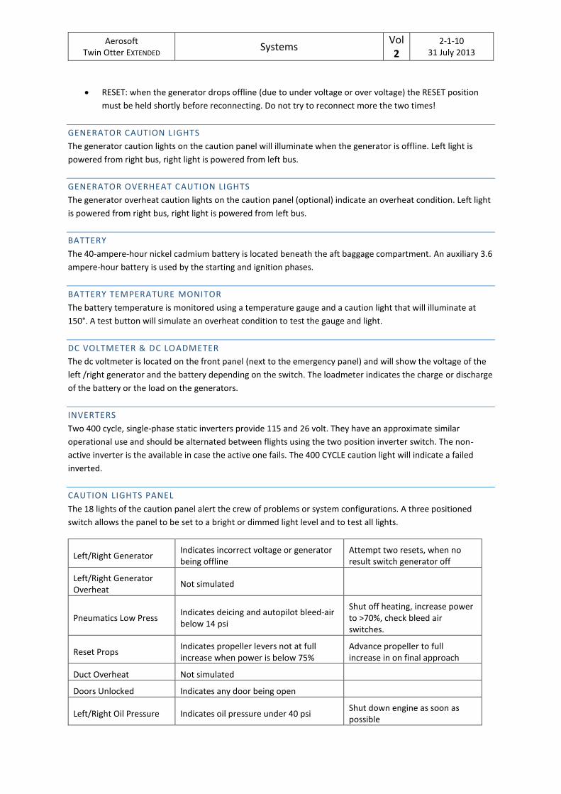
CAUTION LIGHTS PANEL
The 18 lights of the caution panel alert the crew of problems or system configurations. A three positioned
switch allows the panel to be set to a bright or dimmed light level and to test all lights.
Left/Right Generator Indicates incorrect voltage or generator being offline
Attempt two resets, when no result switch generator off
Left/Right Generator Overheat
Not simulated
Pneumatics Low Press Indicates deicing and autopilot bleed-air below 14 psi
Shut off heating, increase power to >70%, check bleed air switches.
Reset Props Indicates propeller levers not at full increase when power is below 75%
Advance propeller to full increase in on final approach
Duct Overheat Not simulated
Doors Unlocked Indicates any door being open
Left/Right Oil Pressure Indicates oil pressure under 40 psi Shut down engine as soon as possible
Aerosoft Twin Otter EXTENDED
Systems Vol 2
2-1-11 31 July 2013
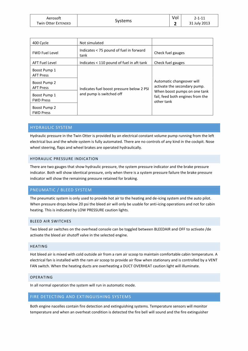
400 Cycle Not simulated
FWD Fuel Level Indicates < 75 pound of fuel in forward tank
Check fuel gauges
AFT Fuel Level Indicates < 110 pound of fuel in aft tank Check fuel gauges
Boost Pump 1 AFT Press
Indicates fuel boost pressure below 2 PSI and pump is switched off
Automatic changeover will activate the secondary pump. When boost pumps on one tank fail, feed both engines from the other tank
Boost Pump 2 AFT Press
Boost Pump 1 FWD Press
Boost Pump 2 FWD Press
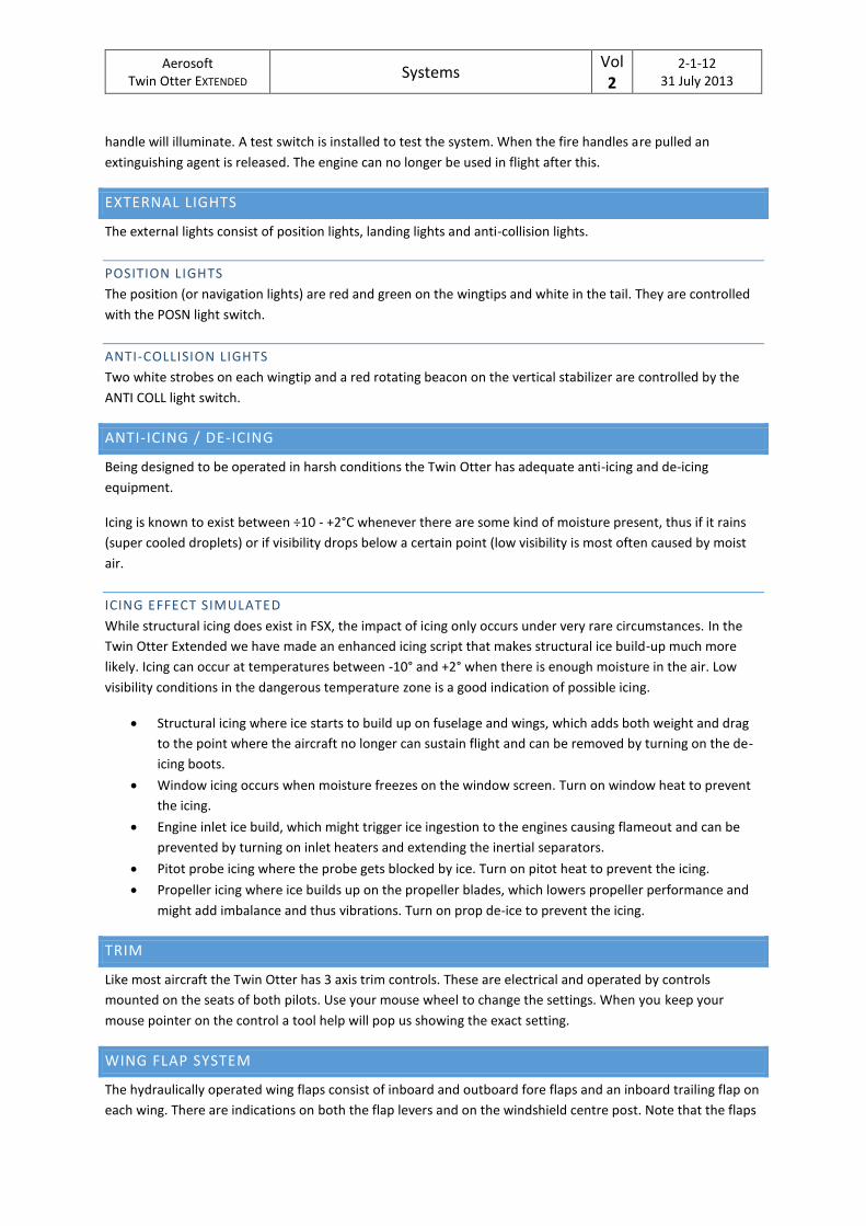
HYDRAULIC SYSTEM
Hydraulic pressure in the Twin Otter is provided by an electrical constant volume pump running from the left
electrical bus and the whole system is fully automated. There are no controls of any kind in the cockpit. Nose
wheel steering, flaps and wheel brakes are operated hydraulically.
HYDRAULIC PRESSURE INDICATION
There are two gauges that show hydraulic pressure, the system pressure indicator and the brake pressure
indicator. Both will show identical pressure, only when there is a system pressure failure the brake pressure
indicator will show the remaining pressure retained for braking.
PNEUMATIC / BLEED SYSTEM
The pneumatic system is only used to provide hot air to the heating and de-icing system and the auto pilot.
When pressure drops below 20 psi the bleed air will only be usable for anti-icing operations and not for cabin
heating. This is indicated by LOW PRESSURE caution lights.
BLEED AIR SWITCHES
Two bleed air switches on the overhead console can be toggled between BLEEDAIR and OFF to activate /de
activate the bleed air shutoff valve in the selected engine.
HEATING
Hot bleed air is mixed with cold outside air from a ram air scoop to maintain comfortable cabin temperature. A
electrical fan is installed with the ram air scoop to provide air flow when stationary and is controlled by a VENT
FAN switch. When the heating ducts are overheating a DUCT OVERHEAT caution light will illuminate.
OPERATING
In all normal operation the system will run in automatic mode.
FIRE DETECTING AND EXTINGUISHING SYSTEMS
Both engine nacelles contain fire detection and extinguishing systems. Temperature sensors will monitor
temperature and when an overheat condition is detected the fire bell will sound and the fire extinguisher
Aerosoft Twin Otter EXTENDED
Systems Vol 2
2-1-12 31 July 2013
handle will illuminate. A test switch is installed to test the system. When the fire handles are pulled an
extinguishing agent is released. The engine can no longer be used in flight after this.
EXTERNAL LIGHTS
The external lights consist of position lights, landing lights and anti-collision lights.
POSITION LIGHTS
The position (or navigation lights) are red and green on the wingtips and white in the tail. They are controlled
with the POSN light switch.
ANTI-COLLISION LIGHTS
Two white strobes on each wingtip and a red rotating beacon on the vertical stabilizer are controlled by the
ANTI COLL light switch.
ANTI-ICING / DE-ICING
Being designed to be operated in harsh conditions the Twin Otter has adequate anti-icing and de-icing
equipment.
Icing is known to exist between ÷10 - +2°C whenever there are some kind of moisture present, thus if it rains
(super cooled droplets) or if visibility drops below a certain point (low visibility is most often caused by moist
air.
ICING EFFECT SIMULATED
While structural icing does exist in FSX, the impact of icing only occurs under very rare circumstances. In the
Twin Otter Extended we have made an enhanced icing script that makes structural ice build-up much more
likely. Icing can occur at temperatures between -10° and +2° when there is enough moisture in the air. Low
visibility conditions in the dangerous temperature zone is a good indication of possible icing.
Structural icing where ice starts to build up on fuselage and wings, which adds both weight and drag
to the point where the aircraft no longer can sustain flight and can be removed by turning on the de-
icing boots.
Window icing occurs when moisture freezes on the window screen. Turn on window heat to prevent
the icing.
Engine inlet ice build, which might trigger ice ingestion to the engines causing flameout and can be
prevented by turning on inlet heaters and extending the inertial separators.
Pitot probe icing where the probe gets blocked by ice. Turn on pitot heat to prevent the icing.
Propeller icing where ice builds up on the propeller blades, which lowers propeller performance and
might add imbalance and thus vibrations. Turn on prop de-ice to prevent the icing.
TRIM
Like most aircraft the Twin Otter has 3 axis trim controls. These are electrical and operated by controls
mounted on the seats of both pilots. Use your mouse wheel to change the settings. When you keep your
mouse pointer on the control a tool help will pop us showing the exact setting.
WING FLAP SYSTEM
The hydraulically operated wing flaps consist of inboard and outboard fore flaps and an inboard trailing flap on
each wing. There are indications on both the flap levers and on the windshield centre post. Note that the flaps
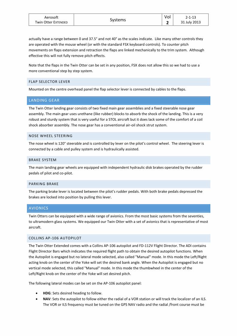
Aerosoft Twin Otter EXTENDED
Systems Vol 2
2-1-13 31 July 2013
actually have a range between 0 and 37.5° and not 40° as the scales indicate. Like many other controls they
are operated with the mouse wheel (or with the standard FSX keyboard controls). To counter pitch
movements on flaps extension and retraction the flaps are linked mechanically to the trim system. Although
effective this will not fully remove pitch effects.
Note that the flaps in the Twin Otter can be set in any position, FSX does not allow this so we had to use a
more conventional step by step system.
FLAP SELECTOR LEVER
Mounted on the centre overhead panel the flap selector lever is connected by cables to the flaps.
LANDING GEAR
The Twin Otter landing gear consists of two fixed main gear assemblies and a fixed steerable nose gear
assembly. The main gear uses urethane (like rubber) blocks to absorb the shock of the landing. This is a very
robust and sturdy system that is very useful for a STOL aircraft but it does lack some of the comfort of a coil
shock absorber assembly. The nose gear has a conventional air-oil shock strut system.
NOSE WHEEL STEERING
The nose wheel is 120° steerable and is controlled by lever on the pilot’s control wheel. The steering lever is
connected by a cable and pulley system and is hydraulically assisted.
BRAKE SYSTEM
The main landing gear wheels are equipped with independent hydraulic disk brakes operated by the rudder
pedals of pilot and co-pilot.
PARKING BRAKE
The parking brake lever is located between the pilot’s rudder pedals. With both brake pedals depressed the
brakes are locked into position by pulling this lever.
AVIONICS
Twin Otters can be equipped with a wide range of avionics. From the most basic systems from the seventies,
to ultramodern glass systems. We equipped our Twin Otter with a set of avionics that is representative of most
aircraft.
COLLINS AP-106 AUTOPILOT
The Twin Otter Extended comes with a Collins AP-106 autopilot and FD-112V Flight Director. The ADI contains
Flight Director Bars which indicates the required flight path to obtain the desired autopilot functions. When
the Autopilot is engaged but no lateral mode selected, also called "Manual" mode. In this mode the Left/Right
acting knob on the center of the Yoke will set the desired bank angle. When the Autopilot is engaged but no
vertical mode selected, this called "Manual" mode. In this mode the thumbwheel in the center of the
Left/Right knob on the center of the Yoke will set desired pitch.
The following lateral modes can be set on the AP-106 autopilot panel:
HDG: Sets desired heading to follow.
NAV: Sets the autopilot to follow either the radial of a VOR station or will track the localizer of an ILS.
The VOR or ILS frequency must be tuned on the GPS NAV radio and the radial /front course must be
Aerosoft Twin Otter EXTENDED
Systems Vol 2
2-1-14 31 July 2013
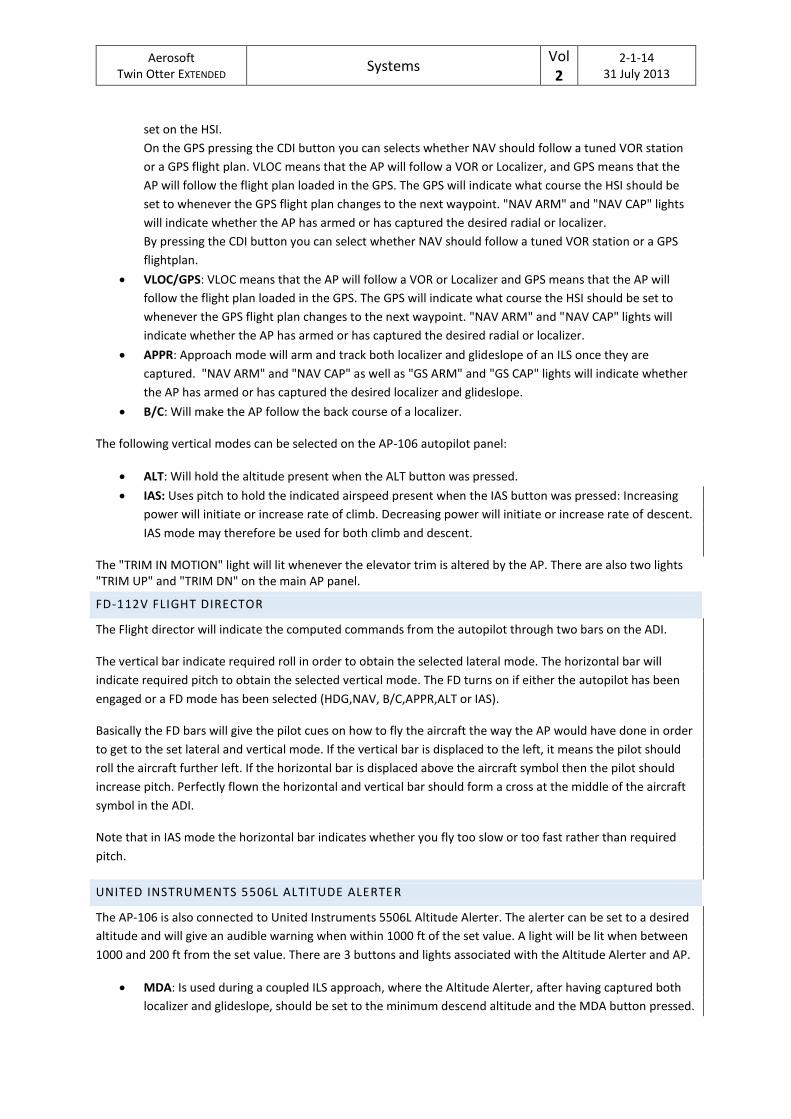
set on the HSI.
On the GPS pressing the CDI button you can selects whether NAV should follow a tuned VOR station
or a GPS flight plan. VLOC means that the AP will follow a VOR or Localizer, and GPS means that the
AP will follow the flight plan loaded in the GPS. The GPS will indicate what course the HSI should be
set to whenever the GPS flight plan changes to the next waypoint. "NAV ARM" and "NAV CAP" lights
will indicate whether the AP has armed or has captured the desired radial or localizer.
By pressing the CDI button you can select whether NAV should follow a tuned VOR station or a GPS
flightplan.
VLOC/GPS: VLOC means that the AP will follow a VOR or Localizer and GPS means that the AP will
follow the flight plan loaded in the GPS. The GPS will indicate what course the HSI should be set to
whenever the GPS flight plan changes to the next waypoint. "NAV ARM" and "NAV CAP" lights will
indicate whether the AP has armed or has captured the desired radial or localizer.
APPR: Approach mode will arm and track both localizer and glideslope of an ILS once they are
captured. "NAV ARM" and "NAV CAP" as well as "GS ARM" and "GS CAP" lights will indicate whether
the AP has armed or has captured the desired localizer and glideslope.
B/C: Will make the AP follow the back course of a localizer.
The following vertical modes can be selected on the AP-106 autopilot panel:
ALT: Will hold the altitude present when the ALT button was pressed.
IAS: Uses pitch to hold the indicated airspeed present when the IAS button was pressed: Increasing
power will initiate or increase rate of climb. Decreasing power will initiate or increase rate of descent.
IAS mode may therefore be used for both climb and descent.
The "TRIM IN MOTION" light will lit whenever the elevator trim is altered by the AP. There are also two lights "TRIM UP" and "TRIM DN" on the main AP panel.
FD-112V FLIGHT DIRECTOR
The Flight director will indicate the computed commands from the autopilot through two bars on the ADI.
The vertical bar indicate required roll in order to obtain the selected lateral mode. The horizontal bar will
indicate required pitch to obtain the selected vertical mode. The FD turns on if either the autopilot has been
engaged or a FD mode has been selected (HDG,NAV, B/C,APPR,ALT or IAS).
Basically the FD bars will give the pilot cues on how to fly the aircraft the way the AP would have done in order
to get to the set lateral and vertical mode. If the vertical bar is displaced to the left, it means the pilot should
roll the aircraft further left. If the horizontal bar is displaced above the aircraft symbol then the pilot should
increase pitch. Perfectly flown the horizontal and vertical bar should form a cross at the middle of the aircraft
symbol in the ADI.
Note that in IAS mode the horizontal bar indicates whether you fly too slow or too fast rather than required
pitch.
UNITED INSTRUMENTS 5506L ALTITUDE ALERTE R
The AP-106 is also connected to United Instruments 5506L Altitude Alerter. The alerter can be set to a desired
altitude and will give an audible warning when within 1000 ft of the set value. A light will be lit when between
1000 and 200 ft from the set value. There are 3 buttons and lights associated with the Altitude Alerter and AP.
MDA: Is used during a coupled ILS approach, where the Altitude Alerter, after having captured both
localizer and glideslope, should be set to the minimum descend altitude and the MDA button pressed.
Aerosoft Twin Otter EXTENDED
Systems Vol 2
2-1-15 31 July 2013
Once the aircraft descends to the set MDA, the AP will level out and maintain the set altitude in order
to prevent from descending below MDA. For landing, once the runway is insight and you are cleared
for landing, the AP should be turned off.
G/A: The Go around button is used when executing a Go Around. Pressing the G/A button will
disengage the AP and set the vertical FD bar for a 8° climb.
ALT ALRT: Will automatically level out the aircraft once it has reached the set altitude when the AP is
in either "Manual" or IAS mode.
When NAV mode is used for tracking a VOR radial and the signals disappears when near vertical to the station,
then "DED REC" mode will be indicated for "Deduced reckoning". In this mode the AP memorizes the heading
present when the signal was lost and will maintain it until past the station where the signal will be received
again.
Note that using the autopilot to acquire an exact altitude, as set on the Altitude Alerter, the ALT button should
not be used. The ALT button simply levels the aircraft at the altitude present when the ALT button was
pressed. To acquire a selected altitude on the Altitude Alerter use either IAS mode or Autopilot manual vertical
mode (Autopilot on, but with IAS, ALT and APPR unselected).
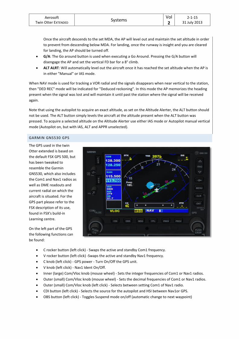
GARMIN GNS530 GPS
The GPS used in the twin
Otter extended is based on
the default FSX GPS 500, but
has been tweaked to
resemble the Garmin
GNS530, which also includes
the Com1 and Nav1 radios as
well as DME readouts and
current radial on which the
aircraft is situated. For the
GPS part please refer to the
FSX description of its use,
found in FSX's build-in
Learning centre.
On the left part of the GPS
the following functions can
be found:
C rocker button (left click) - Swaps the active and standby Com1 frequency.
V rocker button (left click) -Swaps the active and standby Nav1 frequency.
C knob (left click) - GPS power - Turn On/Off the GPS unit.
V knob (left click) - Nav1 Ident On/Off.
Inner (large) Com/Vloc knob (mouse wheel) - Sets the integer frequencies of Com1 or Nav1 radios.
Outer (small) Com/Vloc knob (mouse wheel) - Sets the decimal frequencies of Com1 or Nav1 radios.
Outer (small) Com/Vloc knob (left click) - Selects between setting Com1 of Nav1 radio.
CDI button (left click) - Selects the source for the autopilot and HSI between Nav1or GPS.
OBS button (left click) - Toggles Suspend mode on/off (automatic change to next waypoint)
Aerosoft Twin Otter EXTENDED
Systems Vol 2
2-1-16 31 July 2013
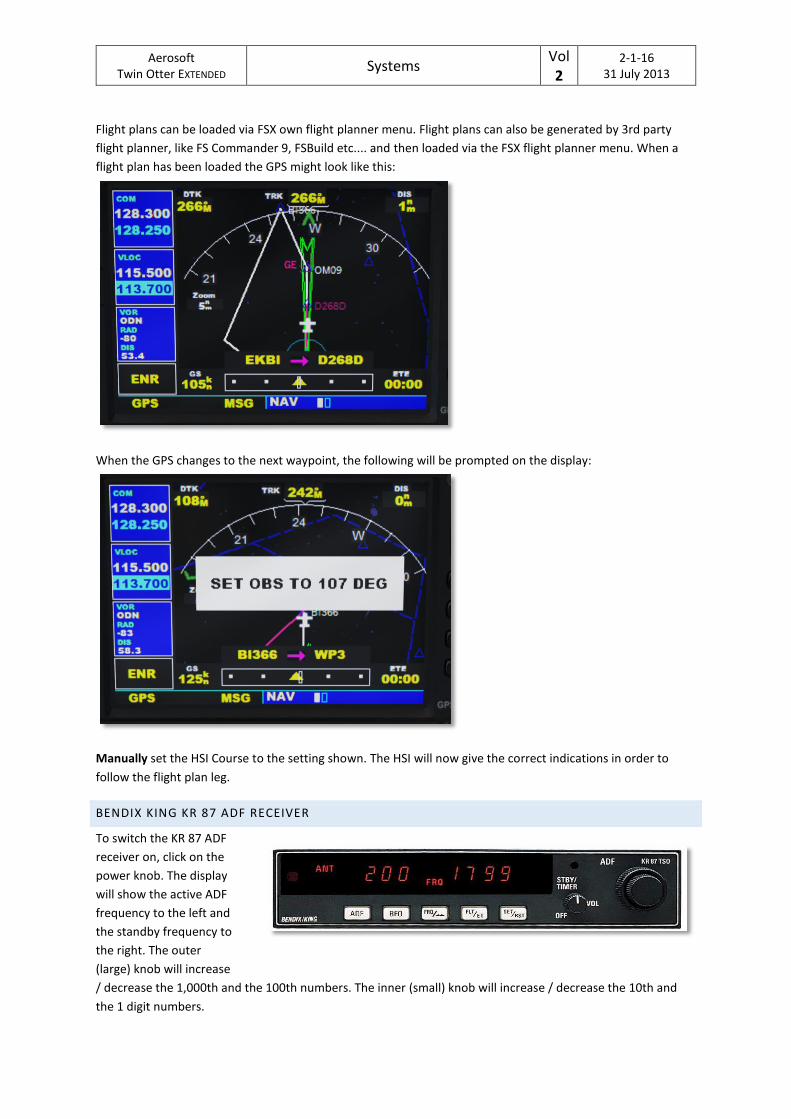
Flight plans can be loaded via FSX own flight planner menu. Flight plans can also be generated by 3rd party
flight planner, like FS Commander 9, FSBuild etc.... and then loaded via the FSX flight planner menu. When a
flight plan has been loaded the GPS might look like this:
When the GPS changes to the next waypoint, the following will be prompted on the display:
Manually set the HSI Course to the setting shown. The HSI will now give the correct indications in order to
follow the flight plan leg.
BENDIX KING KR 87 ADF RECEIVER
To switch the KR 87 ADF
receiver on, click on the
power knob. The display
will show the active ADF
frequency to the left and
the standby frequency to
the right. The outer
(large) knob will increase
/ decrease the 1,000th and the 100th numbers. The inner (small) knob will increase / decrease the 10th and
the 1 digit numbers.
Aerosoft Twin Otter EXTENDED
Systems Vol 2
2-1-17 31 July 2013
Pressing the FREQ/--- button will swap the active frequency with the standby frequency.
Pressing the FLT/ET button will call up the Flight timer - indicated by “FLT” in the upper right corner.
The flight timer indicates time elapsed since the KR 87 was turned on, and can be used to display total flight
time. Subsequent pressing of the FLT/ET, will toggle the display between Flight Time and Elapsed Time -
indicated by “ET” in the lower right corner. When in ET mode, pressing the SET/RST button will reset the ET
timer to zero, thus making it available as a count up timer. When in FLT or ET mode, the active ADF frequency
can be set directly with the outer and inner knobs.
Keeping the SET/RST button pressed for 2 seconds will invoke the countdown timer. “ET” will start to flash and
the countdown minutes can be set with the outer (large) knob, while the seconds can be set with the inner
(small) knob - max setting is 59:59. After having set the timer, press the SET/RST button and the timer will start
to count down from the preset time. During countdown, the active ADF frequency can be set with the outer
and inner knobs. When the countdown timer reaches 00:00 an audible alarm will sound, the timer display will
flash for 15 seconds and the timer will start its normal ET count up sequence.
Pressing the FREQ/--- button, when in FLT or ET mode, will return the KR 87 to the Active / Standby frequency
mode.
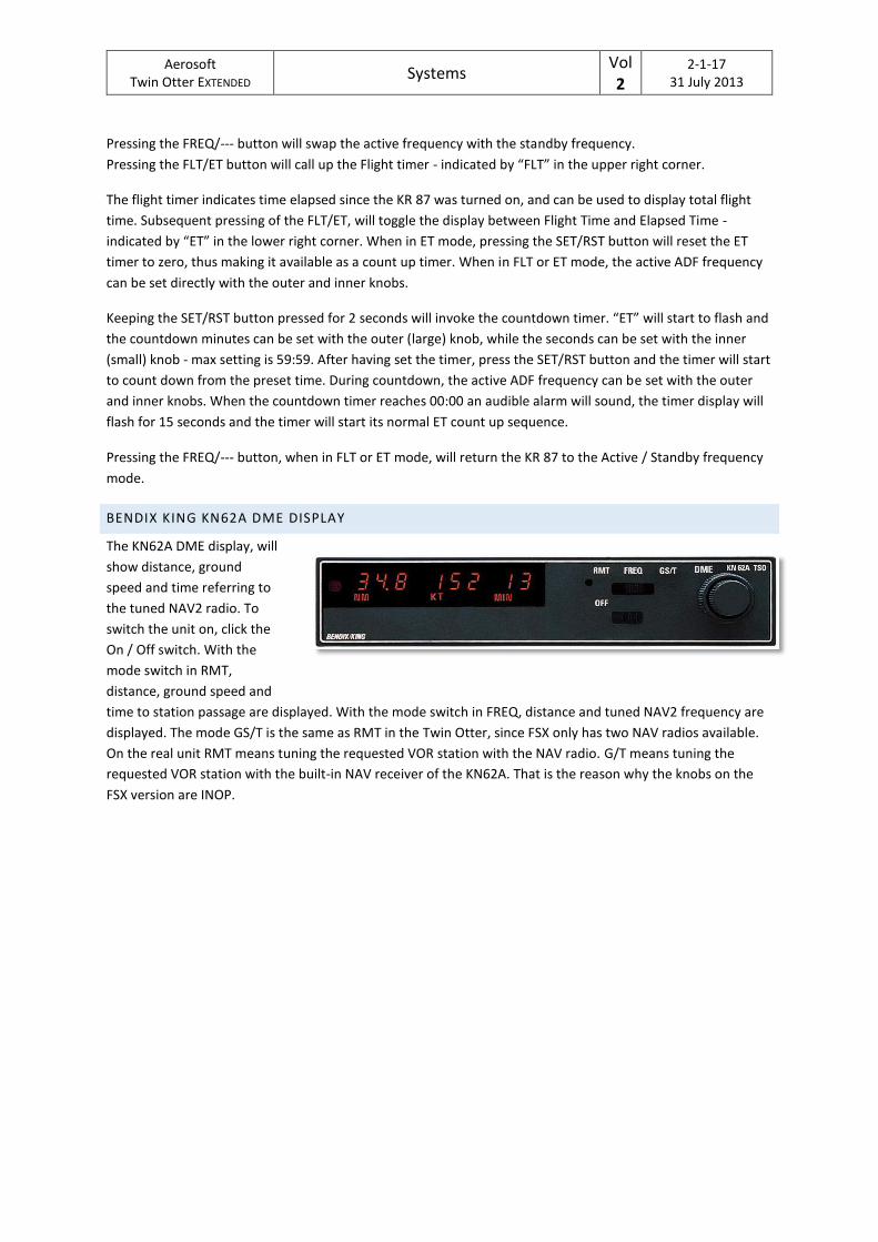
BENDIX KING KN62A DME DISPLAY
The KN62A DME display, will
show distance, ground
speed and time referring to
the tuned NAV2 radio. To
switch the unit on, click the
On / Off switch. With the
mode switch in RMT,
distance, ground speed and
time to station passage are displayed. With the mode switch in FREQ, distance and tuned NAV2 frequency are
displayed. The mode GS/T is the same as RMT in the Twin Otter, since FSX only has two NAV radios available.
On the real unit RMT means tuning the requested VOR station with the NAV radio. G/T means tuning the
requested VOR station with the built-in NAV receiver of the KN62A. That is the reason why the knobs on the
FSX version are INOP.