Embed Size (px)
Citation preview
Pratt & Whitney Engine Services, Inc.249 Vanderbilt AveNorwood, MA 02062
249 Vanderbilt Ave., Norwood, MA 02062, Phone 781-762-8600, Fax 781-762-2287
ADAS/ADAS+ UpgradeInstructions for Continued Airworthiness
TWIN-T-260-1
For Raytheon Model 200, 300, and 1900 Series
Manual Number: TWIN-T-260-1
Preparation Date: November 13, 1999 Prepared By: D Desaulnier
Release Date: April 19, 2000 D Fetherston, Manager of Engineering
Revision Date: February 26, 2009 S Sackos, Manager of Manufacturing Services
Revision Ltr: H
Total Pages: 75
Approvals:
P&W ENGINE SERVICES, INC. ADAS/ADAS+ Upgrade TWIN-T-260-1Raytheon Aircraft Company Model 200, 300, & 1900 Series
- i-TWIN-T-260-1 Pratt & Whitney Engine Services, Inc. Proprietary
PREFACE
Disclaimer
Like all instrumentation, the Pratt & Whitney Engine Services, Inc. ADAS/ADAS+ Upgrade requires knowledgeableinterpretation by the pilot. Any recommendations and operating procedures contained in this manual shall not supersede theAircraft or Engine manufacturer recommendations, operating procedures, or limits. The Pratt & Whitney Engine Services,Inc. ADAS/ADAS+ Upgrade should not be used as a primary guide monitoring the Aircraft and Engine manufacturersoperating limits. Pratt & Whitney Engine Services, Inc. is not liable for any damages resulting from the use of this product.
Proprietary Information Notice
This manual contains proprietary information that is protected by copyright, and all rights are reserved. No portion of thisdocument may be copied, photocopied, reproduced by any means, or translated into another language without the priorwritten permission of Pratt & Whitney Engine Services, Inc.
P&W ENGINE SERVICES, INC. ADAS/ADAS+ Upgrade TWIN-T-260-1Raytheon Aircraft Company Model 200, 300, & 1900 Series
- ii -TWIN-T-260-1 Pratt & Whitney Engine Services, Inc. Proprietary
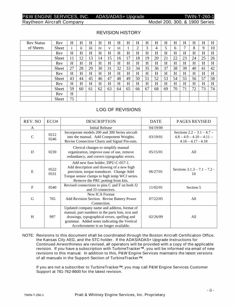
REVISION HISTORY
Rev H H H H H H H H H H H H H H H HRev Statusof Sheets Sheet i ii iii iv v vi 1 2 3 4 5 6 7 8 9 10
Rev H H H H H H H H H H H H H H H HSheet 11 12 13 14 15 16 17 18 19 20 21 22 23 24 25 26Rev H H H H H H H H H H H H H H H H
Sheet 27 28 29 30 31 32 33 34 35 36 37 38 39 40 41 42Rev H H H H H H H H H H H H H H H H
Sheet 43 44 45 46 47 48 49 50 51 52 53 54 55 56 57 58Rev H H H H H H H H H H H H H H H H
Sheet 59 60 61 62 63 64 65 66 67 68 69 70 71 72 73 74Rev H
Sheet 75
LOG OF REVISIONS
REV. NO ECO# DESCRIPTION DATE PAGES REVISED
A Initial Release 04/19/00
C02120246
Incorporate models 200 and 300 Series aircraftinto the manual. Add Component Weights.
Revise Connection Charts and Signal Pin-outs.03/19/01
Sections 2.2 – 3.1 – 4.7 –4.8 – 4.9 – 4.10 – 4.11 –
4.16 – 4.17 - 4.18
D 0230Clerical changes to simplify manual
organization, improve ease of use, removeredundancy, and correct typographic errors.
05/15/01 All
E05220531
Add new fuse holder, DPU-C-057-1.Add description and drawing of a new highprecision, torque transducer. Change Adel
Torque sensor clamps to high temp WCJ series.Remove the PRC potting from kits.
06/27/01Sections 3.1.3 – 7.1 – 7.2 -
10
F 0540Revised connections to pins C and F on both J2
and J3 connectors.11/02/01 Section 5
G 765New ICA Format
Add Revision Section. Revise Battery PowerConnection.
07/22/05 All
H 997
Updated company name and address, format ofmanual, part numbers in the parts lists, text and
drawings, typographical errors, spelling andgrammar. Added notes indicating the Vertical
Accelerometer is no longer available.
02/26/09 All
NOTE: Revisions to this document shall be coordinated through the Boston Aircraft Certification Office,the Kansas City AEG, and the STC holder. If the ADAS/ADAS+ Upgrade Instructions forContinued Airworthiness are revised, all operators will be provided with a copy of the applicablerevision. If you have a subscription with TurbineTracker™, you will be informed via email of newrevisions to this manual. In addition to this, P&W Engine Services maintains the latest versionsof all manuals in the Support Section of TurbineTracker.
If you are not a subscriber to TurbineTracker, you may call P&W Engine Services CustomerSupport at 781-762-8600 for the latest revision.
P&W ENGINE SERVICES, INC. ADAS/ADAS+ Upgrade TWIN-T-260-1Raytheon Aircraft Company Model 200, 300, & 1900 Series
- iii -TWIN-T-260-1 Pratt & Whitney Engine Services, Inc. Proprietary
TABLE OF CONTENTS
1 INTRODUCTION ................................................................................................................................ 1
1.1 SCOPE ...................................................................................................................................................... 11.2 APPLICABILITY ........................................................................................................................................ 11.3 DEFINITIONS AND ABBREVIATIONS ........................................................................................................ 11.4 PRECAUTIONS .......................................................................................................................................... 11.5 UNITS OF MEASURE................................................................................................................................. 11.6 REFERENCED PUBLICATIONS .................................................................................................................. 11.7 DISTRIBUTION ......................................................................................................................................... 1
2 DESCRIPTION .................................................................................................................................... 2
2.1 AIRCRAFT DATA ACQUISITION SYSTEM (ADAS/ADAS+ UPGRADE) GENERAL DESCRIPTION ............. 22.2 SYSTEM PROCESSOR................................................................................................................................ 42.3 INDICATING / CONTROL COMPONENTS ................................................................................................... 6
2.3.1 Trend Switch / Fault Lamp.............................................................................................................. 62.3.2 Circuit Breaker (+28 VDC) ............................................................................................................ 62.3.3 Fuse (+28 VDC).............................................................................................................................. 62.3.4 Communications (COMM) Port...................................................................................................... 6
2.4 AIRFRAME COMPONENTS ........................................................................................................................ 62.4.1 Outside Air Temperature (OAT) Probe........................................................................................... 62.4.2 Pitot/Static Pressure Transducers................................................................................................... 72.4.3 Vertical Accelerometer.................................................................................................................... 82.4.4 Firewall/Pressure Bulkhead Feedthru ............................................................................................ 82.4.5 Discrete Aircraft Signals................................................................................................................. 8
2.5 ENGINE INDICATING COMPONENTS ........................................................................................................ 82.5.1 Engine Temperature Sensors (T4, T4.5, ITT, EGT, MGT, TOT) .................................................... 82.5.2 Engine N1 (Ng) Speed Sensor ......................................................................................................... 82.5.3 Engine N2 Speed Sensor ................................................................................................................. 92.5.4 Propeller (Np) Speed Sensor........................................................................................................... 92.5.5 Engine Torque (Tq) Pressure.......................................................................................................... 9
3 CONTROL AND OPERATION INFORMATION........................................................................... 9
3.1 CAPABILITIES .......................................................................................................................................... 93.1.1 Engine Run Logging...................................................................................................................... 103.1.2 Cycle Logging ............................................................................................................................... 103.1.3 Event Monitoring........................................................................................................................... 103.1.4 Initialization .................................................................................................................................. 113.1.5 SYSTEM MODES .......................................................................................................................... 113.1.6 Run Mode FOR ADAS ONLY........................................................................................................ 123.1.7 Lamp States in Run Mode FOR ADAS ONLY:.............................................................................. 123.1.8 Configuration Mode FOR ADAS ONLY........................................................................................ 133.1.9 Manual Self Test (Loopback Test) FOR ADAS ONLY .................................................................. 133.1.10 Run Mode FOR ADAS+ UPGRADE ONLY.................................................................................. 133.1.11 LAMP STATES IN Run Mode FOR ADAS+ UPGRADE ONLY ................................................... 14
4 SERVICING INFORMATION......................................................................................................... 15
5 MAINTENANCE INSTRUCTIONS ................................................................................................ 15
5.1 RECOMMENDED PERIODIC SCHEDULED SERVICING TASKS.................................................................. 15
P&W ENGINE SERVICES, INC. ADAS/ADAS+ Upgrade TWIN-T-260-1Raytheon Aircraft Company Model 200, 300, & 1900 Series
- iv -TWIN-T-260-1 Pratt & Whitney Engine Services, Inc. Proprietary
5.2 RECOMMENDED PERIODIC SCHEDULED PREVENTIVE MAINTENANCE TESTS/CHECKS ........................ 155.3 RECOMMENDED PERIODIC SCHEDULED INSPECTIONS .......................................................................... 15
5.3.1 System Processor........................................................................................................................... 155.3.2 TREND Switch / Fault Lamp and Download Port ........................................................................ 165.3.3 Pitot / Static Transducers.............................................................................................................. 185.3.4 Outside Air Temperature Probe.................................................................................................... 195.3.5 Torque Transducer........................................................................................................................ 195.3.6 J1, J2, and J3 Harnesses............................................................................................................... 205.3.7 System Test .................................................................................................................................... 20
5.4 RECOMMENDED PERIODIC STRUCTURAL INSPECTIONS ........................................................................ 215.4.1 System Processor........................................................................................................................... 215.4.2 TREND Switch / Fault Lamp and Download Port ........................................................................ 215.4.3 Pitot / Static Transducers.............................................................................................................. 245.4.4 Outside Air Temperature Probe.................................................................................................... 255.4.5 Torque Transducer........................................................................................................................ 26
6 SYSTEM TROUBLESHOOTING.................................................................................................... 27
6.1 SYSTEM PROCESSOR.............................................................................................................................. 286.1.1 Processor Test ............................................................................................................................... 296.1.2 Download Port Test ...................................................................................................................... 306.1.3 Cockpit Fault Lamp Display Test.................................................................................................. 316.1.4 Torque Transducer and Channel Test........................................................................................... 326.1.5 Pitot / Static Transducer and Channel Test .................................................................................. 336.1.6 Outside Air Temperature Test ....................................................................................................... 346.1.7 P&W Engine Services Voltage to Frequency Converter............................................................... 366.1.8 Additional Aircraft Signals............................................................................................................ 36
7 REMOVAL AND REPLACEMENT INFORMATION................................................................. 37
7.1 PROCESSOR REMOVAL/REPLACEMENT ................................................................................................. 377.2 TREND SWITCH REMOVAL/REPLACEMENT ......................................................................................... 377.3 DOWNLOAD PORT REMOVAL/REPLACEMENT....................................................................................... 387.4 PITOT/STATIC TRANSDUCER REMOVAL/REPLACEMENT ...................................................................... 387.5 OAT REMOVAL/REPLACEMENT............................................................................................................ 397.6 TORQUE TRANSDUCER REMOVAL/REPLACEMENT ............................................................................... 39
8 SPECIAL INSPECTION REQUIREMENTS ................................................................................. 40
9 APPLICATION OF PROTECTIVE TREATMENTS.................................................................... 40
10 DATA................................................................................................................................................... 40
10.1 PARTS LIST ............................................................................................................................................ 4010.1.1 Part Kits by Aircraft for ADAS ONLY: ......................................................................................... 4010.1.2 Part Kits By Aircraft for ADAS+ Upgrade ONLY:....................................................................... 4310.1.3 Components for ADAS and ADAS+ Upgrade by Kit Number ...................................................... 46
11 LIST OF SPECIAL TOOLS.............................................................................................................. 51
12 FOR COMMUTER CATEGORY AIRCRAFT .............................................................................. 51
13 RECOMMENDED OVERHAUL PERIODS .................................................................................. 51
P&W ENGINE SERVICES, INC. ADAS/ADAS+ Upgrade TWIN-T-260-1Raytheon Aircraft Company Model 200, 300, & 1900 Series
- v -TWIN-T-260-1 Pratt & Whitney Engine Services, Inc. Proprietary
14 AIRWORTHINESS LIMITATIONS ............................................................................................... 51
15 DIAGRAMS ........................................................................................................................................ 52
15.1 ADAS CONNECTOR SIGNAL POINTS ..................................................................................................... 5215.1.1 Power/ Sensor Cable J1, 15 Pin S Keyed Connector.................................................................... 5215.1.2 Sensor Cable J2, 15 Pin SA Keyed Connector .............................................................................. 5315.1.3 Cockpit Trend / Sensor Cable, J3, 37 Pin S Keyed Connector ..................................................... 5415.1.4 COMM CABLE HARNESS............................................................................................................ 55
15.1.4.1 COCKPIT TREND SWITCH HARNESS – SINGLE DISPLAY ........................................ 5515.1.4.2 COCKPIT TREND SWITCH HARNESS – DUAL DISPLAY ........................................... 55
15.2 ADAS+ UPGRADE CONNECTOR SIGNAL POINTS .................................................................................. 5615.2.1 Power/ Sensor Cable J1, 15 Pin S Keyed Connector.................................................................... 5615.2.2 Sensor Cable J2, 15 Pin SA Keyed Connector .............................................................................. 5715.2.3 Cockpit Trend / Sensor Cable, J3, 37 Pin S Keyed Connector ..................................................... 5815.2.4 COMM CABLE HARNESS............................................................................................................ 59
15.2.4.1 COCKPIT TREND SWITCH HARNESS – SINGLE DISPLAY ........................................ 5915.2.4.2 COCKPIT TREND SWITCH HARNESS – DUAL DISPLAY ........................................... 59
16 WIRING DIAGRAM ......................................................................................................................... 60
16.1 ADAS/ADAS+ UPGRADE CONNECTION CHART – 1900 & 1900C ....................................................... 6016.2 ADAS/ADAS+ UPGRADE CONNECTION CHART – 1900D.................................................................... 6116.3 ADAS/ADAS+ UPGRADE CONNECTION CHART – 200 & 200T ........................................................... 6216.4 ADAS/ADAS+ UPGRADE CONNECTION CHART – 200CT, A200, A200C, & A200CT........................ 6316.5 ADAS/ADAS+ UPGRADE CONNECTION CHART – B200C, B200CT, B200, & B200T ........................ 6416.6 ADAS/ADAS+ UPGRADE CONNECTION CHART – 300 ........................................................................ 6516.7 ADAS/ADAS+ UPGRADE CONNECTION CHART – B300...................................................................... 6616.8 ADAS/ADAS+ UPGRADE CONNECTION CHART – B300C & 300LW .................................................. 6716.9 ADAS - WIRING DIAGRAM NO. 1 ......................................................................................................... 6816.10 ADAS - WIRING DIAGRAM NO. 2 ......................................................................................................... 6916.11 ADAS - WIRING DIAGRAM NO. 3 ......................................................................................................... 7016.12 ADAS - WIRING DIAGRAM NO. 4 ......................................................................................................... 7116.13 ADAS+ UPGRADE - WIRING DIAGRAM NO. 1 ...................................................................................... 7216.14 ADAS+ UPGRADE - WIRING DIAGRAM NO. 2 ...................................................................................... 7316.15 ADAS+ UPGRADE - WIRING DIAGRAM NO. 3 ...................................................................................... 7416.16 ADAS+ UPGRADE - WIRING DIAGRAM NO. 4 ...................................................................................... 75
LIST OF FIGURES
FIGURE 1: CAPABILITIES OF DATA TRANSMISSION SYSTEM...................................................................................................... 3FIGURE 2: PROCESSOR .............................................................................................................................................................. 4FIGURE 3: TYPICAL AVIONICS COMPARTMENT SHOCK MOUNT DETAIL ................................................................................... 5FIGURE 4: TYPICAL ENGINE COMPARTMENT SHOCK MOUNT DETAIL ...................................................................................... 5FIGURE 5: TREND SWITCH/FAULT LAMP................................................................................................................................. 6FIGURE 6: COMMUNICATIONS PORT.......................................................................................................................................... 6FIGURE 7: OAT PROBE ............................................................................................................................................................. 7FIGURE 8: PITOT TRANSDUCER ................................................................................................................................................. 7FIGURE 9: STATIC TRANSDUCER ............................................................................................................................................... 7FIGURE 10: VERTICAL ACCELEROMETER .................................................................................................................................. 8FIGURE 11: TORQUE TRANSDUCER ........................................................................................................................................... 9FIGURE 12: BRACKET TO AVIONICS TRAY MOUNTING ........................................................................................................... 16
P&W ENGINE SERVICES, INC. ADAS/ADAS+ Upgrade TWIN-T-260-1Raytheon Aircraft Company Model 200, 300, & 1900 Series
- vi -TWIN-T-260-1 Pratt & Whitney Engine Services, Inc. Proprietary
FIGURE 13: ADAS TREND SWITCH AND DOWNLOAD PORT (DISCRETE MOUNT) ................................................................. 16FIGURE 14: ADAS TREND SWITCH / FAULT LAMP & DOWNLOAD PORT (CENTER CONSOLE MOUNT)................................. 16FIGURE 15: ADAS+ UPGRADE TREND SWITCH AND DOWNLOAD PORT (DISCRETE MOUNT) ............................................... 17FIGURE 16: ADAS+ UPGRADE TREND SWITCH / FAULT LAMP & DOWNLOAD PORT (CENTER CONSOLE MOUNT) .............. 17FIGURE 17: TREND SWITCH/FAULT LAMP CONNECTOR ........................................................................................................ 17FIGURE 18: DOWNLOAD PORT CONNECTOR ............................................................................................................................ 18FIGURE 19: PITOT / STATIC TRANSDUCER INSTALLATION ....................................................................................................... 18FIGURE 20: PITOT/STATIC WIRING.......................................................................................................................................... 19FIGURE 21: OAT PROBE WIRING ............................................................................................................................................ 19FIGURE 22: TORQUE TRANSDUCER WIRING ............................................................................................................................ 20FIGURE 23: PROCESSOR MOUNTING CONFIGURATION ............................................................................................................ 21FIGURE 24: ADAS TREND SWITCH AND DOWNLOAD PORT (DISCRETE MOUNT) ................................................................. 22FIGURE 25: ADAS TREND SWITCH / FAULT LAMP & DOWNLOAD PORT (CENTER CONSOLE MOUNT)................................. 22FIGURE 26: ADAS+ UPGRADE TREND SWITCH AND DOWNLOAD PORT (DISCRETE MOUNT) ............................................... 23FIGURE 27: ADAS+ UPGRADE TREND SWITCH / FAULT LAMP & DOWNLOAD PORT (CENTER CONSOLE MOUNT) .............. 23FIGURE 28: PITOT/STATIC INSTALLATION (SIDE VIEW) .......................................................................................................... 24FIGURE 29: OAT PROBE ILLUSTRATION ................................................................................................................................. 25FIGURE 30: TORQUE TRANSDUCER INSTALLATION CONFIGURATION...................................................................................... 26FIGURE 31: SYSTEM PROCESSOR START UP TEST FLOW DIAGRAM ........................................................................................ 28FIGURE 32: SYSTEM PROCESSOR TEST FLOW DIAGRAM ......................................................................................................... 29FIGURE 33: DOWNLOAD PORT TEST FLOW DIAGRAM ............................................................................................................. 30FIGURE 34: COCKPIT FAULT LAMP AND DOWNLOAD PORT WIRING ....................................................................................... 30FIGURE 35: COCKPIT FAULT LAMP TEST FLOW DIAGRAM ...................................................................................................... 31FIGURE 36: TORQUE TRANSDUCER TEST FLOW DIAGRAM...................................................................................................... 32FIGURE 37: TORQUE WIRING .................................................................................................................................................. 32FIGURE 38: PITOT / STATIC TRANSDUCER TEST FLOW DIAGRAM ........................................................................................... 33FIGURE 39: PITOT / STATIC WIRING ........................................................................................................................................ 33FIGURE 40: ADAS OAT PROBE TEST FLOW DIAGRAM .......................................................................................................... 34FIGURE 41: ADAS OAT WIRING ............................................................................................................................................ 34FIGURE 42: ADAS+ UPGRADE OAT PROBE TEST FLOW DIAGRAM........................................................................................ 35FIGURE 43: ADAS+ UPGRADE OAT WIRING ......................................................................................................................... 35FIGURE 44: VOLTAGE TO FREQUENCY CONVERTERS .............................................................................................................. 36FIGURE 45: ADAS – WITH TORQUE TRANSDUCERS AND WITHOUT VOLTAGE TO FREQUENCY CONVERTER .......................... 68FIGURE 46: ADAS – WITHOUT TORQUE TRANSDUCERS AND WITHOUT VOLTAGE TO FREQUENCY CONVERTER ................... 69FIGURE 47: ADAS – WITH TORQUE TRANSDUCERS AND WITH VOLTAGE TO FREQUENCY CONVERTER ................................ 70FIGURE 48: ADAS – WITH TORQUE TRANSDUCERS AND WITH VOLTAGE TO FREQUENCY CONVERTER ................................ 71FIGURE 49: ADAS+ UPGRADE – WITH TORQUE TRANSDUCERS AND WITHOUT VOLTAGE TO FREQUENCY CONVERTER ....... 72FIGURE 50: ADAS+ UPGRADE – WITHOUT TORQUE TRANSDUCERS AND WITHOUT VOLTAGE TO FREQUENCY CONVERTER. 73FIGURE 51: ADAS+ UPGRADE – WITH TORQUE TRANSDUCERS AND WITH VOLTAGE TO FREQUENCY CONVERTER.............. 74FIGURE 52: ADAS+ UPGRADE – WITHOUT TORQUE TRANSDUCERS AND WITH VOLTAGE TO FREQUENCY CONVERTER ....... 75
LIST OF TABLES
TABLE 1: PITOT TRANSDUCER SPECIFICATIONS ........................................................................................................................ 7TABLE 2: STATIC TRANSDUCER SPECIFICATIONS ...................................................................................................................... 8TABLE 3: TORQUE TRANSDUCER SPECIFICATIONS .................................................................................................................... 9
P&W ENGINE SERVICES, INC. ADAS/ADAS+ Upgrade TWIN-T-260-1Raytheon Aircraft Company Model 200, 300, & 1900 Series
- 1 -TWIN-T-260-1 Pratt & Whitney Engine Services, Inc. Proprietary
1 INTRODUCTION
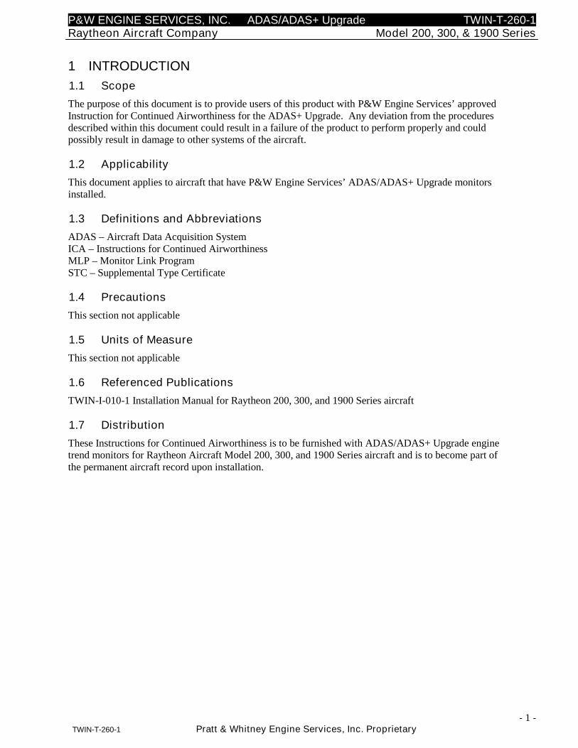
1.1 Scope
The purpose of this document is to provide users of this product with P&W Engine Services’ approvedInstruction for Continued Airworthiness for the ADAS+ Upgrade. Any deviation from the proceduresdescribed within this document could result in a failure of the product to perform properly and couldpossibly result in damage to other systems of the aircraft.
1.2 Applicability
This document applies to aircraft that have P&W Engine Services’ ADAS/ADAS+ Upgrade monitorsinstalled.
1.3 Definitions and Abbreviations
ADAS – Aircraft Data Acquisition SystemICA – Instructions for Continued AirworthinessMLP – Monitor Link ProgramSTC – Supplemental Type Certificate
1.4 Precautions
This section not applicable
1.5 Units of Measure
This section not applicable
1.6 Referenced Publications
TWIN-I-010-1 Installation Manual for Raytheon 200, 300, and 1900 Series aircraft
1.7 Distribution
These Instructions for Continued Airworthiness is to be furnished with ADAS/ADAS+ Upgrade enginetrend monitors for Raytheon Aircraft Model 200, 300, and 1900 Series aircraft and is to become part ofthe permanent aircraft record upon installation.
P&W ENGINE SERVICES, INC. ADAS/ADAS+ Upgrade TWIN-T-260-1Raytheon Aircraft Company Model 200, 300, & 1900 Series
- 2 -TWIN-T-260-1 Pratt & Whitney Engine Services, Inc. Proprietary
2 DESCRIPTION
2.1 Aircraft Data Acquisition System (ADAS/ADAS+ Upgrade) GeneralDescription
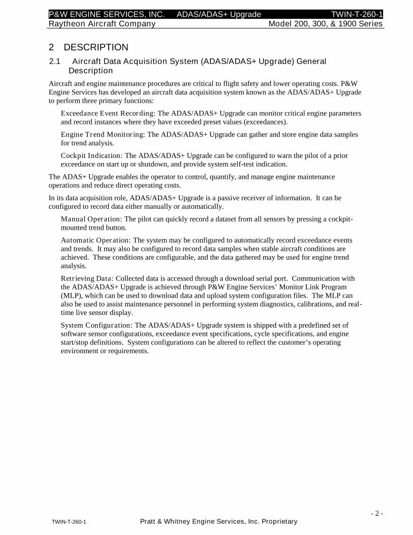
Aircraft and engine maintenance procedures are critical to flight safety and lower operating costs. P&WEngine Services has developed an aircraft data acquisition system known as the ADAS/ADAS+ Upgradeto perform three primary functions:
Exceedance Event Recording: The ADAS/ADAS+ Upgrade can monitor critical engine parametersand record instances where they have exceeded preset values (exceedances).
Engine Trend Monitoring: The ADAS/ADAS+ Upgrade can gather and store engine data samplesfor trend analysis.
Cockpit Indication: The ADAS/ADAS+ Upgrade can be configured to warn the pilot of a priorexceedance on start up or shutdown, and provide system self-test indication.
The ADAS+ Upgrade enables the operator to control, quantify, and manage engine maintenanceoperations and reduce direct operating costs.
In its data acquisition role, ADAS/ADAS+ Upgrade is a passive receiver of information. It can beconfigured to record data either manually or automatically.
Manual Operation: The pilot can quickly record a dataset from all sensors by pressing a cockpit-mounted trend button.
Automatic Operation: The system may be configured to automatically record exceedance eventsand trends. It may also be configured to record data samples when stable aircraft conditions areachieved. These conditions are configurable, and the data gathered may be used for engine trendanalysis.
Retrieving Data: Collected data is accessed through a download serial port. Communication withthe ADAS/ADAS+ Upgrade is achieved through P&W Engine Services’ Monitor Link Program(MLP), which can be used to download data and upload system configuration files. The MLP canalso be used to assist maintenance personnel in performing system diagnostics, calibrations, and real-time live sensor display.
System Configuration: The ADAS/ADAS+ Upgrade system is shipped with a predefined set ofsoftware sensor configurations, exceedance event specifications, cycle specifications, and enginestart/stop definitions. System configurations can be altered to reflect the customer’s operatingenvironment or requirements.
P&W ENGINE SERVICES, INC. ADAS/ADAS+ Upgrade TWIN-T-260-1Raytheon Aircraft Company Model 200, 300, & 1900 Series
- 3 -TWIN-T-260-1 Pratt & Whitney Engine Services, Inc. Proprietary
Figure 1: Capabilities of Data Transmission System
P&W ENGINE SERVICES, INC. ADAS/ADAS+ Upgrade TWIN-T-260-1Raytheon Aircraft Company Model 200, 300, & 1900 Series
- 4 -TWIN-T-260-1 Pratt & Whitney Engine Services, Inc. Proprietary
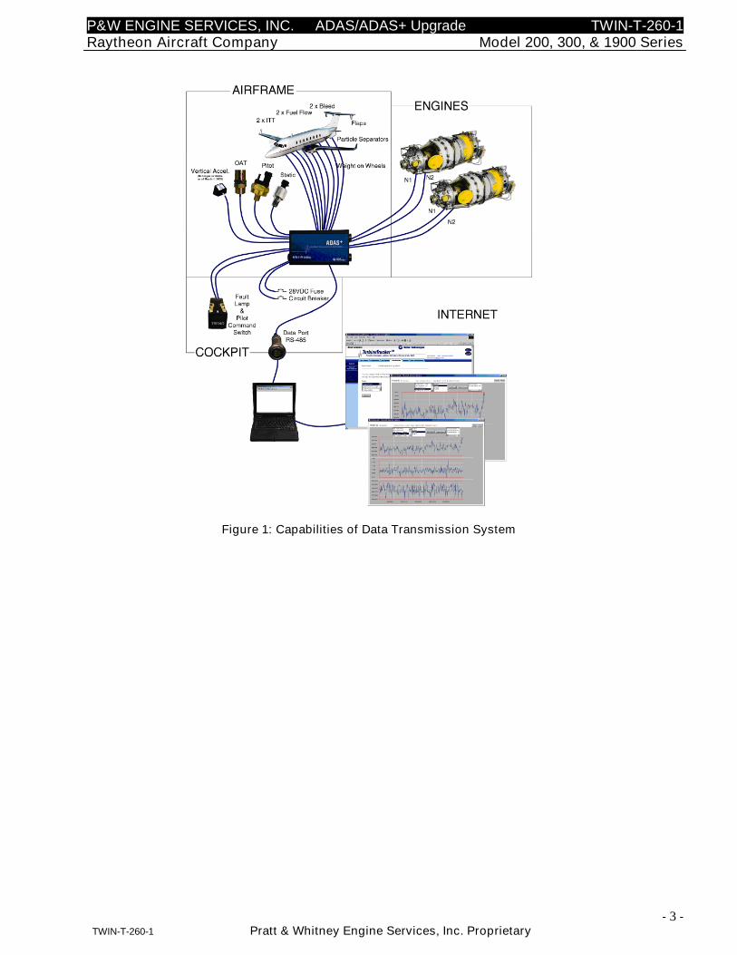
2.2 System Processor
The processor (Figure 2) collects and interprets data from airframe and engine mounted components.Data is retrieved by the operator through an RS485 cockpit interface connection. The processor does notrequire access during flight.
The processor measures 3.7” high by 6.9” long by 2.7” deep and weighs 2.3 lbs. An aluminum bracketwith Lord Aerospace shock mounts is used to mount the processor to the aircraft.
Figure 2: Processor
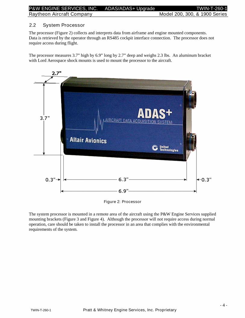
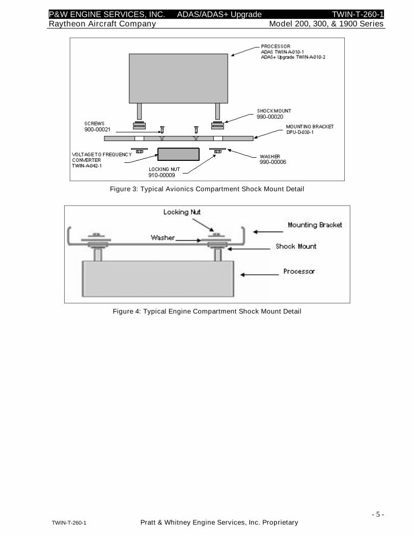
The system processor is mounted in a remote area of the aircraft using the P&W Engine Services suppliedmounting brackets (Figure 3 and Figure 4). Although the processor will not require access during normaloperation, care should be taken to install the processor in an area that complies with the environmentalrequirements of the system.
P&W ENGINE SERVICES, INC. ADAS/ADAS+ Upgrade TWIN-T-260-1Raytheon Aircraft Company Model 200, 300, & 1900 Series
- 5 -TWIN-T-260-1 Pratt & Whitney Engine Services, Inc. Proprietary
Figure 3: Typical Avionics Compartment Shock Mount Detail
Figure 4: Typical Engine Compartment Shock Mount Detail
P&W ENGINE SERVICES, INC. ADAS/ADAS+ Upgrade TWIN-T-260-1Raytheon Aircraft Company Model 200, 300, & 1900 Series
- 6 -TWIN-T-260-1 Pratt & Whitney Engine Services, Inc. Proprietary
2.3 Indicating / Control Components
Following are the descriptions and functions of the control components and indicators.
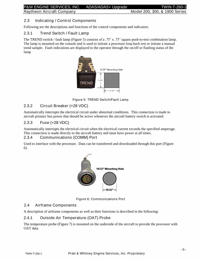
2.3.1 Trend Switch / Fault Lamp
The TREND switch / fault lamp (Figure 5) consists of a .75˝ x .75˝ square push-to-test combination lamp.The lamp is mounted on the console and is used to initiate a processor loop back test or initiate a manualtrend sample. Fault indications are displayed to the operator through the on/off or flashing status of thelamp
Figure 5: TREND Switch/Fault Lamp
2.3.2 Circuit Breaker (+28 VDC)
Automatically interrupts the electrical circuit under abnormal conditions. This connection is made toaircraft primary bus power that should be active whenever the aircraft battery switch is activated.
2.3.3 Fuse (+28 VDC)
Automatically interrupts the electrical circuit when the electrical current exceeds the specified amperage.This connection is made directly to the aircraft battery and must have power at all times.
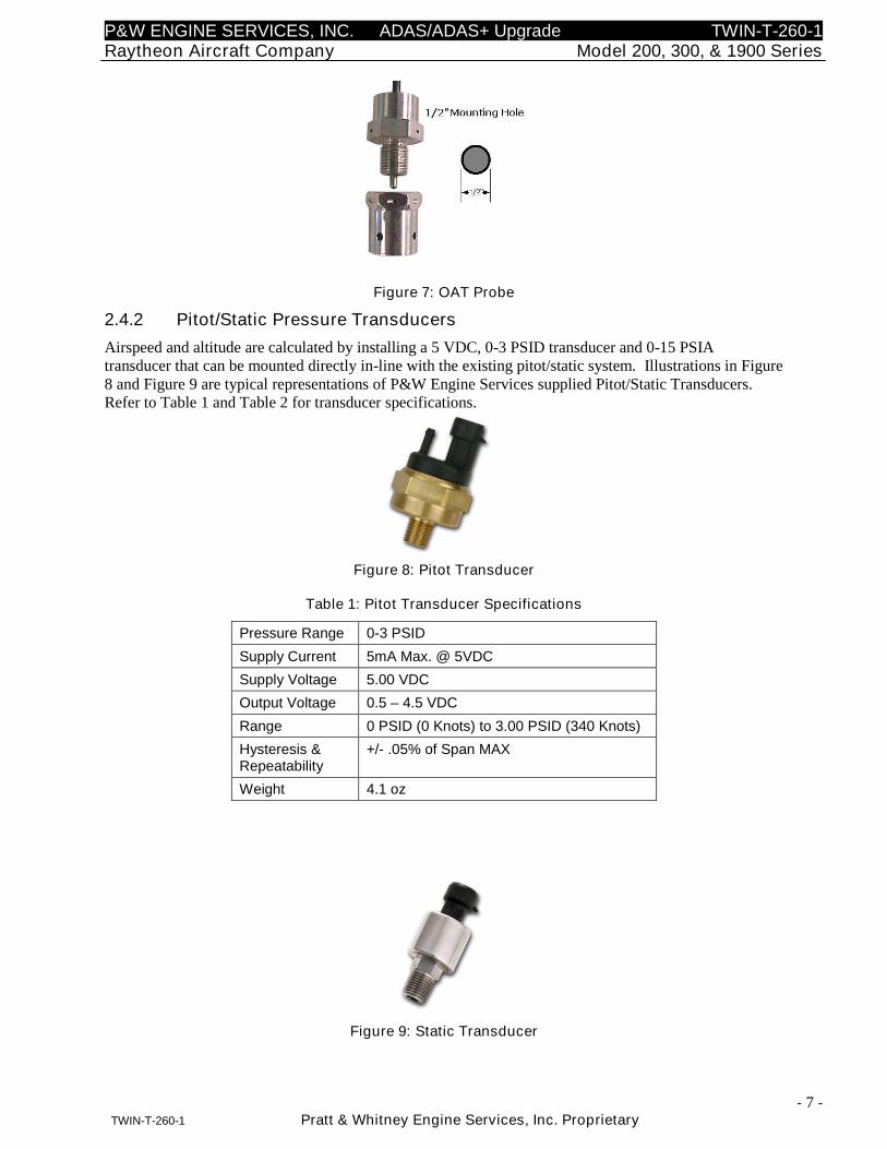
2.3.4 Communications (COMM) Port
Used to interface with the processor. Data can be transferred and downloaded through this port (Figure6).
Figure 6: Communications Port
2.4 Airframe Components
A description of airframe components as well as their functions is described in the following:
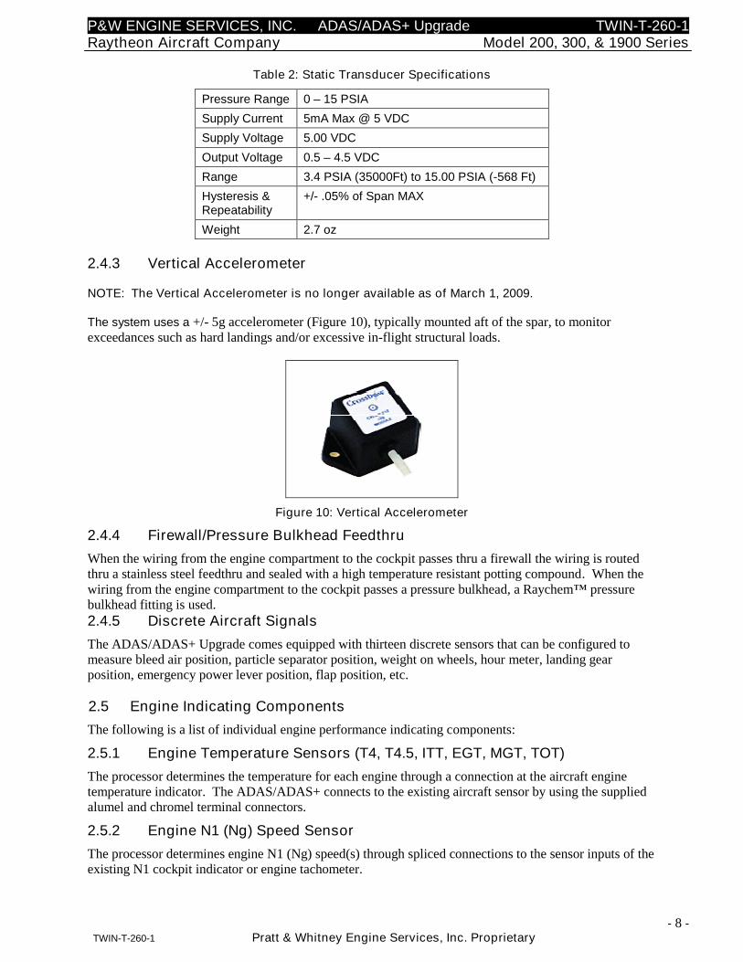
2.4.1 Outside Air Temperature (OAT) Probe
The temperature probe (Figure 7) is mounted on the underside of the aircraft to provide the processor withOAT data.
P&W ENGINE SERVICES, INC. ADAS/ADAS+ Upgrade TWIN-T-260-1Raytheon Aircraft Company Model 200, 300, & 1900 Series
- 7 -TWIN-T-260-1 Pratt & Whitney Engine Services, Inc. Proprietary
Figure 7: OAT Probe
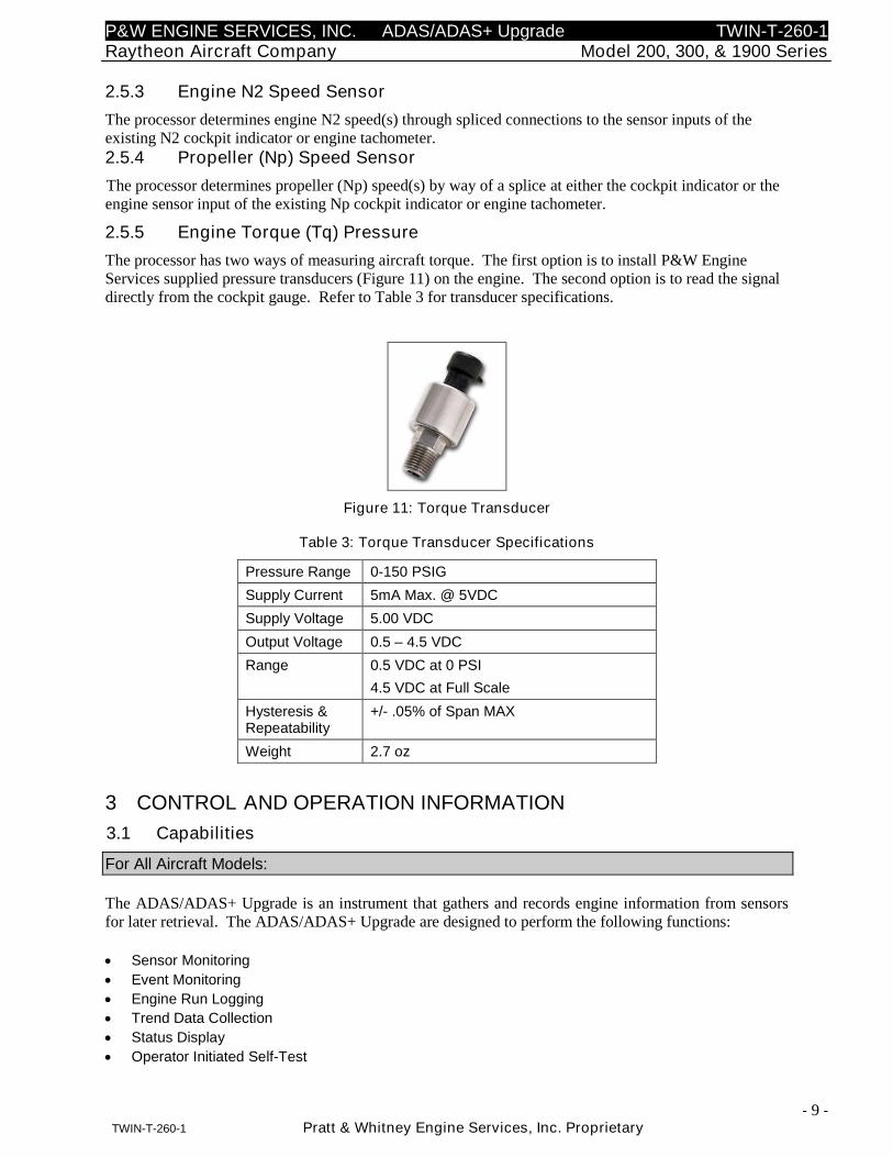
2.4.2 Pitot/Static Pressure Transducers
Airspeed and altitude are calculated by installing a 5 VDC, 0-3 PSID transducer and 0-15 PSIAtransducer that can be mounted directly in-line with the existing pitot/static system. Illustrations in Figure8 and Figure 9 are typical representations of P&W Engine Services supplied Pitot/Static Transducers.Refer to Table 1 and Table 2 for transducer specifications.
Figure 8: Pitot Transducer
Table 1: Pitot Transducer Specifications
Pressure Range 0-3 PSID
Supply Current 5mA Max. @ 5VDC
Supply Voltage 5.00 VDC
Output Voltage 0.5 – 4.5 VDC
Range 0 PSID (0 Knots) to 3.00 PSID (340 Knots)
Hysteresis &Repeatability
+/- .05% of Span MAX
Weight 4.1 oz
Figure 9: Static Transducer
P&W ENGINE SERVICES, INC. ADAS/ADAS+ Upgrade TWIN-T-260-1Raytheon Aircraft Company Model 200, 300, & 1900 Series
- 8 -TWIN-T-260-1 Pratt & Whitney Engine Services, Inc. Proprietary
Table 2: Static Transducer Specifications
Pressure Range 0 – 15 PSIA
Supply Current 5mA Max @ 5 VDC
Supply Voltage 5.00 VDC
Output Voltage 0.5 – 4.5 VDC
Range 3.4 PSIA (35000Ft) to 15.00 PSIA (-568 Ft)
Hysteresis &Repeatability
+/- .05% of Span MAX
Weight 2.7 oz
2.4.3 Vertical Accelerometer
NOTE: The Vertical Accelerometer is no longer available as of March 1, 2009.
The system uses a +/- 5g accelerometer (Figure 10), typically mounted aft of the spar, to monitorexceedances such as hard landings and/or excessive in-flight structural loads.
Figure 10: Vertical Accelerometer
2.4.4 Firewall/Pressure Bulkhead Feedthru
When the wiring from the engine compartment to the cockpit passes thru a firewall the wiring is routedthru a stainless steel feedthru and sealed with a high temperature resistant potting compound. When thewiring from the engine compartment to the cockpit passes a pressure bulkhead, a Raychem™ pressurebulkhead fitting is used.
2.4.5 Discrete Aircraft Signals
The ADAS/ADAS+ Upgrade comes equipped with thirteen discrete sensors that can be configured tomeasure bleed air position, particle separator position, weight on wheels, hour meter, landing gearposition, emergency power lever position, flap position, etc.
2.5 Engine Indicating Components
The following is a list of individual engine performance indicating components:
2.5.1 Engine Temperature Sensors (T4, T4.5, ITT, EGT, MGT, TOT)
The processor determines the temperature for each engine through a connection at the aircraft enginetemperature indicator. The ADAS/ADAS+ connects to the existing aircraft sensor by using the suppliedalumel and chromel terminal connectors.
2.5.2 Engine N1 (Ng) Speed Sensor
The processor determines engine N1 (Ng) speed(s) through spliced connections to the sensor inputs of theexisting N1 cockpit indicator or engine tachometer.
P&W ENGINE SERVICES, INC. ADAS/ADAS+ Upgrade TWIN-T-260-1Raytheon Aircraft Company Model 200, 300, & 1900 Series
- 9 -TWIN-T-260-1 Pratt & Whitney Engine Services, Inc. Proprietary
2.5.3 Engine N2 Speed Sensor
The processor determines engine N2 speed(s) through spliced connections to the sensor inputs of theexisting N2 cockpit indicator or engine tachometer.
2.5.4 Propeller (Np) Speed Sensor
The processor determines propeller (Np) speed(s) by way of a splice at either the cockpit indicator or theengine sensor input of the existing Np cockpit indicator or engine tachometer.
2.5.5 Engine Torque (Tq) Pressure
The processor has two ways of measuring aircraft torque. The first option is to install P&W EngineServices supplied pressure transducers (Figure 11) on the engine. The second option is to read the signaldirectly from the cockpit gauge. Refer to Table 3 for transducer specifications.
Figure 11: Torque Transducer
Table 3: Torque Transducer Specifications
Pressure Range 0-150 PSIG
Supply Current 5mA Max. @ 5VDC
Supply Voltage 5.00 VDC
Output Voltage 0.5 – 4.5 VDC
Range 0.5 VDC at 0 PSI
4.5 VDC at Full Scale
Hysteresis &Repeatability
+/- .05% of Span MAX
Weight 2.7 oz
3 CONTROL AND OPERATION INFORMATION
3.1 Capabilities
For All Aircraft Models:
The ADAS/ADAS+ Upgrade is an instrument that gathers and records engine information from sensorsfor later retrieval. The ADAS/ADAS+ Upgrade are designed to perform the following functions:
Sensor Monitoring
Event Monitoring
Engine Run Logging
Trend Data Collection
Status Display
Operator Initiated Self-Test
P&W ENGINE SERVICES, INC. ADAS/ADAS+ Upgrade TWIN-T-260-1Raytheon Aircraft Company Model 200, 300, & 1900 Series
- 10 -TWIN-T-260-1 Pratt & Whitney Engine Services, Inc. Proprietary
Automatic Self-Test
Data Retrieval
Diagnostics Control
Calibration Parameter Control
Configuration Control
3.1.1 Engine Run Logging
The ADAS/ADAS+ Upgrade are capable of recording engine runs. For each run the following isrecorded for each engine:
Engine start date and time Engine run duration Maximum sensor value Cycle count
3.1.2 Cycle Logging
The ADAS/ADAS+ Upgrade can be configured for up to four different types of cycle count types duringeach engine run.
Incremental cycles (selectable sensor) Duration cycle (selectable sensor) Peak value cycle (one or two selectable sensors) Cumulative valley cycle (selectable sensor)
3.1.3 Event Monitoring
The ADAS/ADAS+ Upgrade can be configured to monitor and record airframe or engine exceedances orevents. Up to twenty basic AFM exceedances and operator specific events can be configured. Each eventrecord includes the date and time of the event, its duration and average and maximum sensor values.Events can be set to comprise inputs from either one or two sensors.
P&W ENGINE SERVICES, INC. ADAS/ADAS+ Upgrade TWIN-T-260-1Raytheon Aircraft Company Model 200, 300, & 1900 Series
- 11 -TWIN-T-260-1 Pratt & Whitney Engine Services, Inc. Proprietary
For All Listed Aircraft Models:
3.1.4 Initialization
When the system initializes, both TREND lamps indicate the various stages of the process. The processorinitialization sequence proceeds as follows:
When the processor’s power is first applied, each cockpit lamp will illuminate for approximately 2seconds while the system performs self-tests. The following self-tests are performed during initialization:
RAM Test PROM Test Temporary Memory Test Data Log Memory Test
If any of these tests fail, the lamp will remain on.
If the test passes, the lamp will extinguish and the processor will enter a system mode.
3.1.5 SYSTEM MODES
There are two system modes: Run Mode, and Configuration Mode.
For data collection it is normally operated in Run Mode.
For communication through the serial port with a laptop computer for the purposes of data transfer it isgenerally operated in Configuration Mode.
Configuration Mode is entered when a Communication cable is attached and the cable’s Run/Configureswitch is set to CONF. Run Mode is entered when the cable is not attached, or when it is attached and theRun/Configure Switch is set to RUN.
RUN is the default mode of operation. In this mode, the processor ignores all external serialcommands. The system is dedicated to monitoring sensors, exceedances, and cycles. During thisperiod a trend data sample can be stored manually by the pilot (if the cockpit is equipped with aTREND button) or by automatic sampling. No modifications of the processor settings arepossible in Run Mode. The ADAS/ADAS+ Upgrade may write records to system memory butcannot erase them while in this state. In Run Mode, the P&W Engine Services ADAS/ADAS+Upgrade can output a fixed format report of the current values of its sensors, along with otherflight information at a rate of 1 Hz through the serial port (Live Data Display). Run Mode isdefined by an ungrounded state of the Run/Configure input lines.
CONFIGURATION mode is the data transfer mode of operation. In this mode the ADAS/ADAS+Upgrade is dedicated to processing commands coming through the serial port from the MLP computer.The processor does not perform any monitoring of sensors, exceedances or cycles except in response to auser command. The ADAS/ADAS+ Upgrade does not write new records to system memory in this mode.Commands are available to retrieve or clear existing log data and configuration records while inCONFIGURATION Mode. It is defined by a grounded state on the Run/Configure input line.
P&W ENGINE SERVICES, INC. ADAS/ADAS+ Upgrade TWIN-T-260-1Raytheon Aircraft Company Model 200, 300, & 1900 Series
- 12 -TWIN-T-260-1 Pratt & Whitney Engine Services, Inc. Proprietary
The following section describes the condition of the cockpit lamps after initialization for:
Run Mode with the engine not running. Run Mode with the engine running. Configuration Mode.
3.1.6 Run Mode FOR ADAS ONLY
There are three possible states for the system in Run Mode. The states determine the lamp display.
1.) Normal2.) Warning3.) Error
Definitions:
In Normal state, the system is performing normally.
In Warning state, the system is indicating one or more of the following:
1. An exceedance was recorded2. The available data log memory is getting low3. The system has undergone a Factory Reset
In Error state, the system is indicating one or more of the following:
1. There is an internal program error2. There is a failed sensor channel3. There was a time slice (data) overflow4. The data log is full
3.1.7 Lamp States in Run Mode FOR ADAS ONLY:
While the engine is not running:
Lamp Out means Normal statusLamp Flashing means Warning statusLamp ON Continuously means Error status
Pressing the TREND switch with the lamp out will initiate a manual (“Loopback”) self test.Pressing the TREND switch with the lamp flashing will extinguish it IF in Warning state.
While the engine is running:
Lamp Flashing means a trend data sample is being taken, either automatically, or manuallyLamp Is Out for all other states.
Pressing the TREND switch with the lamp out will initiate a trend data sample.
P&W ENGINE SERVICES, INC. ADAS/ADAS+ Upgrade TWIN-T-260-1Raytheon Aircraft Company Model 200, 300, & 1900 Series
- 13 -TWIN-T-260-1 Pratt & Whitney Engine Services, Inc. Proprietary
3.1.8 Configuration Mode FOR ADAS ONLY
Lamp States in Configuration Mode
Lamp Out means Normal statusLamp Flashing means Warning statusLamp ON Continuously means Error status
While Flashing or On, Pressing the TREND switch will extinguish the lamp.While Off, Pressing the TREND switch will initiate a manual (Loopback) self test and send anacknowledgement of the button press to the serial communications port.
Note if the lamp is flashing, or ON, pressing the switch twice will accomplish bothof the above actions. It will extinguish the lamp and then perform a LoopbackTest. The lamp will remain off at the completion of the test.
3.1.9 Manual Self Test (Loopback Test) FOR ADAS ONLY
The Loopback test is a simple manual test that allows the user to check the operation of the lamp andCPU. It may be initiated in Configuration Mode, or in Run Mode when the engine is not running and thelamp is extinguished. Pressing the TREND switch initiates the Loop back Test.
Lamp Flashes for 5 Seconds means a Loopback Test was initiated, and is successful. The processorand lamp are functional.
3.1.10 Run Mode FOR ADAS+ UPGRADE ONLY
There are four possible states for the system in Run Mode. Each state determines the fault lamp display.
System States:
1. Normal
2. Maintenance
3. Caution
4. Fault
Definitions:
In Normal state, the system is performing normally OR recorded an input programmed toindicate Normal state.
In Maintenance state, the system recorded an input programmed to indicate Maintenancestate.
In Caution state, the system recorded an input programmed to indicate Caution state.
In Fault state, the system has failed OR the system recorded an input programmed toindicate Fault state.
P&W ENGINE SERVICES, INC. ADAS/ADAS+ Upgrade TWIN-T-260-1Raytheon Aircraft Company Model 200, 300, & 1900 Series
- 14 -TWIN-T-260-1 Pratt & Whitney Engine Services, Inc. Proprietary
3.1.11 LAMP STATES IN Run Mode FOR ADAS+ UPGRADE ONLY
While the Engine is Not Running Mode
Engine Not Running Mode is defined as anytime engine temperature is less than Engine Start Criteria(usually < 450 ºC).
Lamp Out means Normal state
Lamp Flashing means Maintenance state, if pressing the TREND switch stops the flashing
Lamp Flashing means Caution state, if pressing the TREND switch does not stop the flashing
Lamp Solid means Fault state
Pressing the TREND switch with the lamp out will initiate a manual (“Loopback”) self test.
Pressing the TREND switch with the lamp flashing will extinguish the lamp if in the Maintenance state.
While the Engine is Running Mode
Engine Running Mode is defined as anytime Ng is greater than Engine Run Criteria (usually > 55%).
Lamp Flashing means a trend data sample is being taken, either automatically, or manually
Lamp Is Out for all states. Lamp states are not allowed to report during Engine Running Mode.Pressing the TREND switch will initiate a trend data sample.
P&W ENGINE SERVICES, INC. ADAS/ADAS+ Upgrade TWIN-T-260-1Raytheon Aircraft Company Model 200, 300, & 1900 Series
- 15 -TWIN-T-260-1 Pratt & Whitney Engine Services, Inc. Proprietary
4 SERVICING INFORMATION
This section is not applicable
5 MAINTENANCE INSTRUCTIONS
Scheduled Maintenance Program tasks are to be added to the aircraft operator’s appropriate maintenanceprogram as follows:5.1 Recommended Periodic Scheduled Servicing Tasks
The P&W Engine Services ADAS/ADAS+ Upgrade has been designed with the latest solid-statetechnology. The only component that has a limited life span is the internal battery. This battery, undernormal operating conditions, is expected to last 10 years. If the battery is discharged, the processor mustbe returned to P&W Engine Services for battery replacement.
5.2 Recommended Periodic Scheduled Preventive Maintenance Tests/Checks
None Required5.3 Recommended Periodic Scheduled Inspections
The following information should be used to insure the continuous and trouble free operation of theADAS/ADAS+ Upgrade. These inspection steps should be followed during every other 100-hourinspection.
These instructions describe general inspection methods. All inspections should look for generaldeterioration of hoses, brackets, and any other component of the ADAS/ADAS+ Upgrade system. Otherthan the specific periodic inspections, maintenance is on-condition, and there is no other scheduledmaintenance.
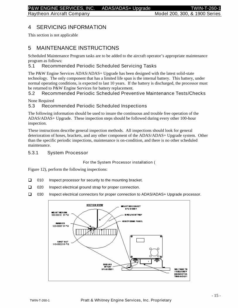
5.3.1 System Processor
For the System Processor installation (
Figure 12), perform the following inspections:
010 Inspect processor for security to the mounting bracket.
020 Inspect electrical ground strap for proper connection.
030 Inspect electrical connectors for proper connection to ADAS/ADAS+ Upgrade processor.
P&W ENGINE SERVICES, INC. ADAS/ADAS+ Upgrade TWIN-T-260-1Raytheon Aircraft Company Model 200, 300, & 1900 Series
- 16 -TWIN-T-260-1 Pratt & Whitney Engine Services, Inc. Proprietary
Figure 12: Bracket to Avionics Tray Mounting
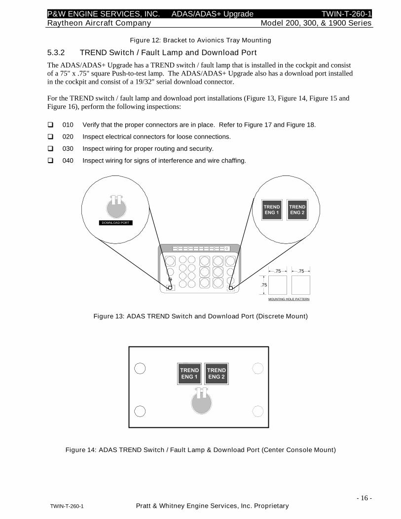
5.3.2 TREND Switch / Fault Lamp and Download Port
The ADAS/ADAS+ Upgrade has a TREND switch / fault lamp that is installed in the cockpit and consistof a 75" x .75" square Push-to-test lamp. The ADAS/ADAS+ Upgrade also has a download port installedin the cockpit and consist of a 19/32" serial download connector.
For the TREND switch / fault lamp and download port installations (Figure 13, Figure 14, Figure 15 andFigure 16), perform the following inspections:
010 Verify that the proper connectors are in place. Refer to Figure 17 and Figure 18.
020 Inspect electrical connectors for loose connections.
030 Inspect wiring for proper routing and security.
040 Inspect wiring for signs of interference and wire chaffing.
TRENDENG 1
DOWNLOAD PORT
MOUNTING HOLE PATTERN
.75
.75
TRENDENG 2
.75
Figure 13: ADAS TREND Switch and Download Port (Discrete Mount)
TRENDENG 1
TRENDENG 2
ECTMPORT
Figure 14: ADAS TREND Switch / Fault Lamp & Download Port (Center Console Mount)
P&W ENGINE SERVICES, INC. ADAS/ADAS+ Upgrade TWIN-T-260-1Raytheon Aircraft Company Model 200, 300, & 1900 Series
- 17 -TWIN-T-260-1 Pratt & Whitney Engine Services, Inc. Proprietary
TREND
DOWNLOAD PORT
MOUNTING HOLE PATTERN
.75
.75
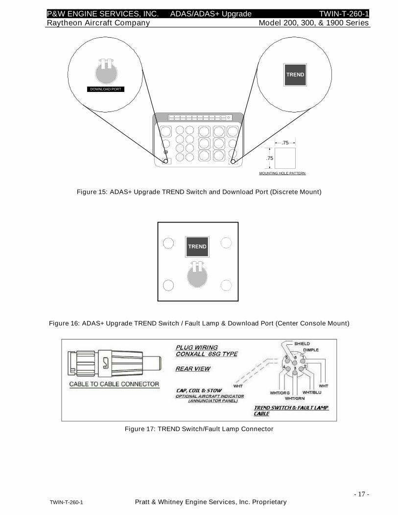
Figure 15: ADAS+ Upgrade TREND Switch and Download Port (Discrete Mount)
TREND
ECTMPORT
Figure 16: ADAS+ Upgrade TREND Switch / Fault Lamp & Download Port (Center Console Mount)
Figure 17: TREND Switch/Fault Lamp Connector
P&W ENGINE SERVICES, INC. ADAS/ADAS+ Upgrade TWIN-T-260-1Raytheon Aircraft Company Model 200, 300, & 1900 Series
- 18 -TWIN-T-260-1 Pratt & Whitney Engine Services, Inc. Proprietary
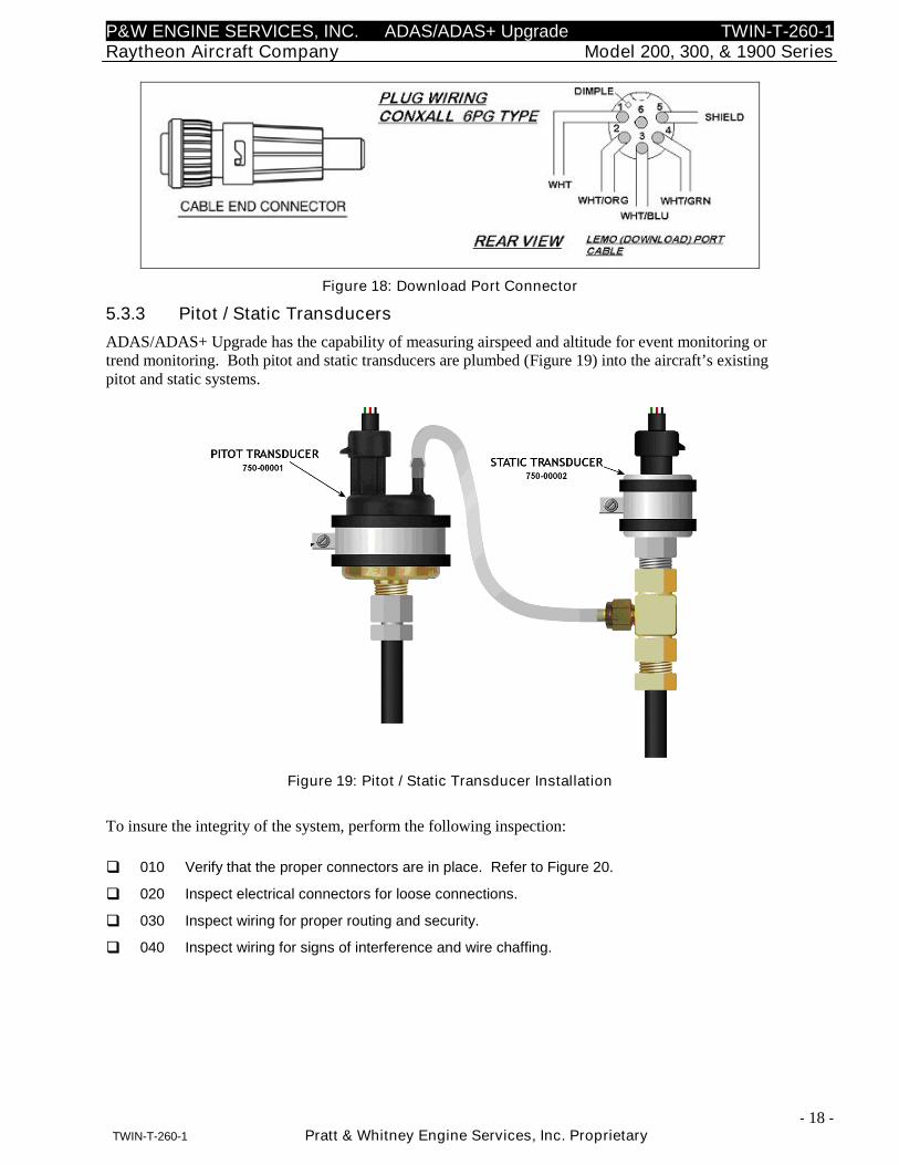
Figure 18: Download Port Connector
5.3.3 Pitot / Static Transducers
ADAS/ADAS+ Upgrade has the capability of measuring airspeed and altitude for event monitoring ortrend monitoring. Both pitot and static transducers are plumbed (Figure 19) into the aircraft’s existingpitot and static systems.
Figure 19: Pitot / Static Transducer Installation
To insure the integrity of the system, perform the following inspection:
010 Verify that the proper connectors are in place. Refer to Figure 20.
020 Inspect electrical connectors for loose connections.
030 Inspect wiring for proper routing and security.
040 Inspect wiring for signs of interference and wire chaffing.
P&W ENGINE SERVICES, INC. ADAS/ADAS+ Upgrade TWIN-T-260-1Raytheon Aircraft Company Model 200, 300, & 1900 Series
- 19 -TWIN-T-260-1 Pratt & Whitney Engine Services, Inc. Proprietary
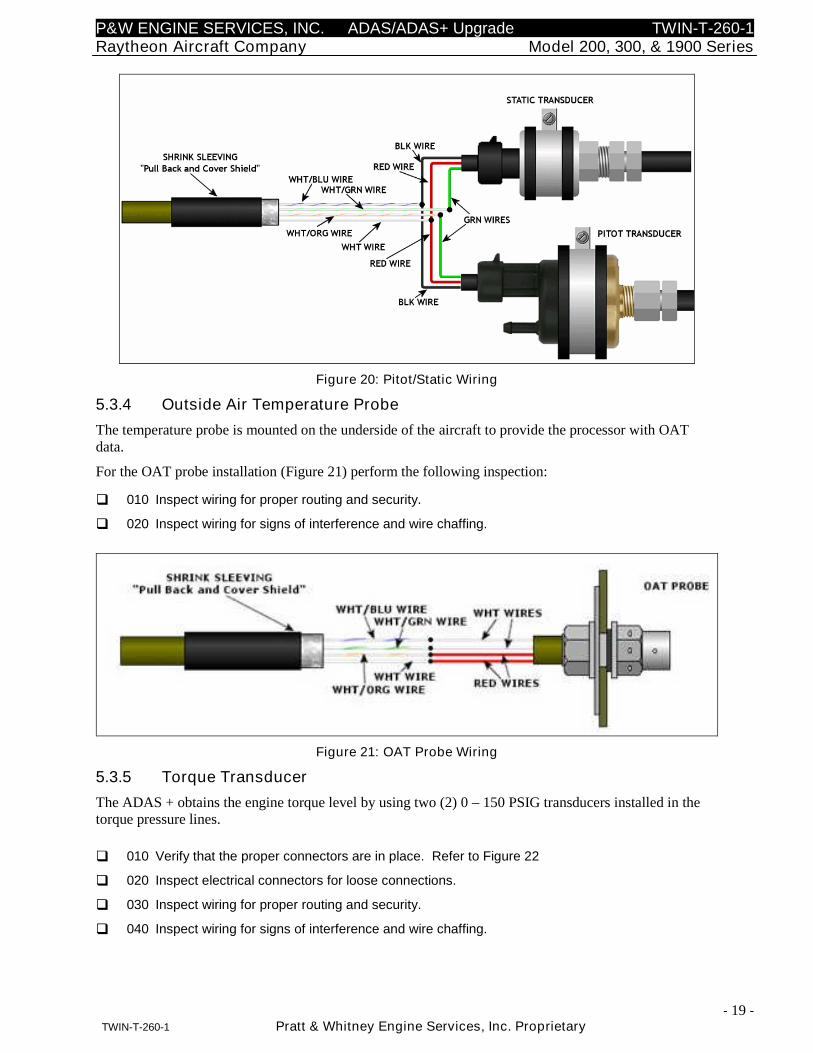
Figure 20: Pitot/Static Wiring
5.3.4 Outside Air Temperature Probe
The temperature probe is mounted on the underside of the aircraft to provide the processor with OATdata.
For the OAT probe installation (Figure 21) perform the following inspection:
010 Inspect wiring for proper routing and security.
020 Inspect wiring for signs of interference and wire chaffing.
Figure 21: OAT Probe Wiring
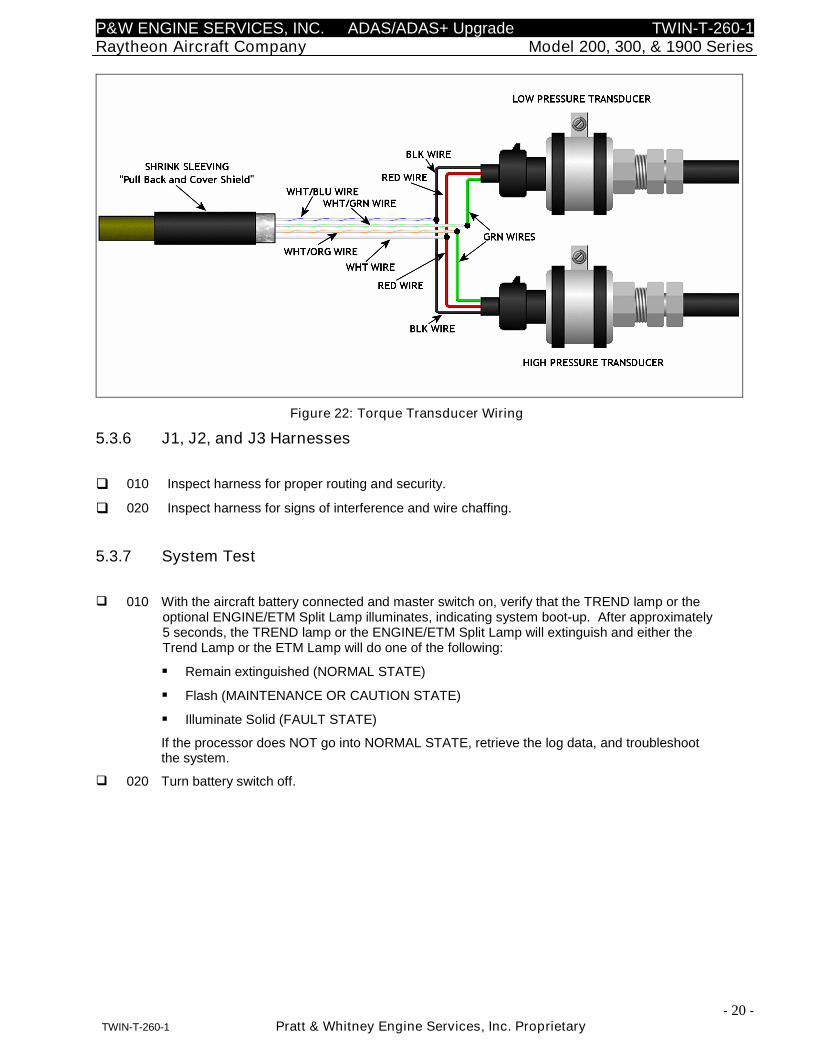
5.3.5 Torque Transducer
The ADAS + obtains the engine torque level by using two (2) 0 – 150 PSIG transducers installed in thetorque pressure lines.
010 Verify that the proper connectors are in place. Refer to Figure 22
020 Inspect electrical connectors for loose connections.
030 Inspect wiring for proper routing and security.
040 Inspect wiring for signs of interference and wire chaffing.
P&W ENGINE SERVICES, INC. ADAS/ADAS+ Upgrade TWIN-T-260-1Raytheon Aircraft Company Model 200, 300, & 1900 Series
- 20 -TWIN-T-260-1 Pratt & Whitney Engine Services, Inc. Proprietary
Figure 22: Torque Transducer Wiring
5.3.6 J1, J2, and J3 Harnesses
010 Inspect harness for proper routing and security.
020 Inspect harness for signs of interference and wire chaffing.
5.3.7 System Test
010 With the aircraft battery connected and master switch on, verify that the TREND lamp or theoptional ENGINE/ETM Split Lamp illuminates, indicating system boot-up. After approximately5 seconds, the TREND lamp or the ENGINE/ETM Split Lamp will extinguish and either theTrend Lamp or the ETM Lamp will do one of the following:
Remain extinguished (NORMAL STATE)
Flash (MAINTENANCE OR CAUTION STATE)
Illuminate Solid (FAULT STATE)
If the processor does NOT go into NORMAL STATE, retrieve the log data, and troubleshootthe system.
020 Turn battery switch off.
P&W ENGINE SERVICES, INC. ADAS/ADAS+ Upgrade TWIN-T-260-1Raytheon Aircraft Company Model 200, 300, & 1900 Series
- 21 -TWIN-T-260-1 Pratt & Whitney Engine Services, Inc. Proprietary
5.4 Recommended Periodic Structural Inspections
The following information should be used to insure the continuous and trouble free operation of theADAS/ADAS+ Upgrade. These inspection steps should be followed during every other 100-hourinspection.
These instructions describe general inspection methods. All inspections should look for generaldeterioration of hoses, brackets, and any other component of the ADAS+ Upgrade system. Other than thespecific periodic inspections, maintenance is on-condition, and there is no other scheduled maintenance.
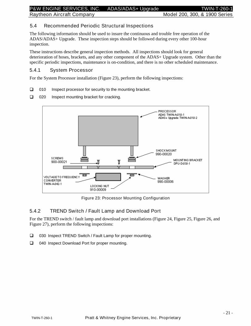
5.4.1 System Processor
For the System Processor installation (Figure 23), perform the following inspections:
010 Inspect processor for security to the mounting bracket.
020 Inspect mounting bracket for cracking.
Figure 23: Processor Mounting Configuration
5.4.2 TREND Switch / Fault Lamp and Download Port
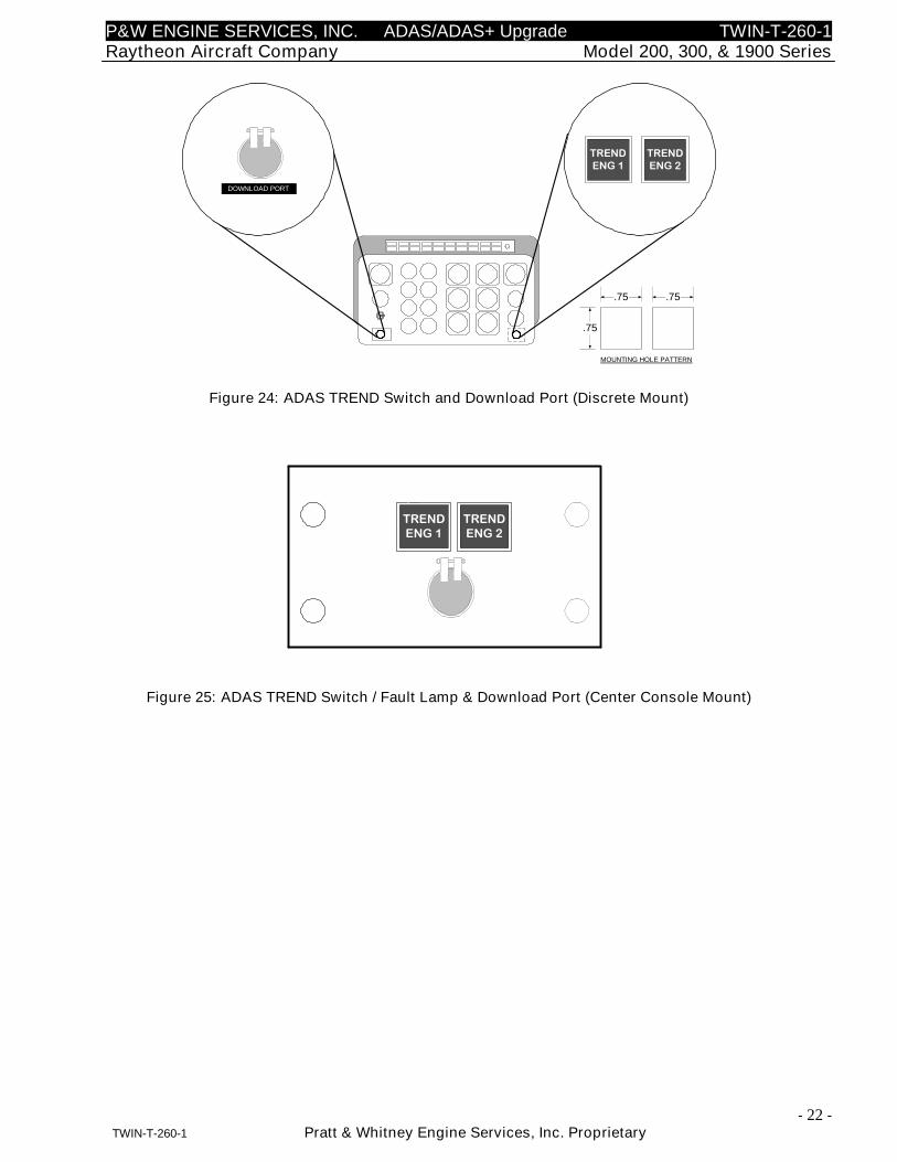
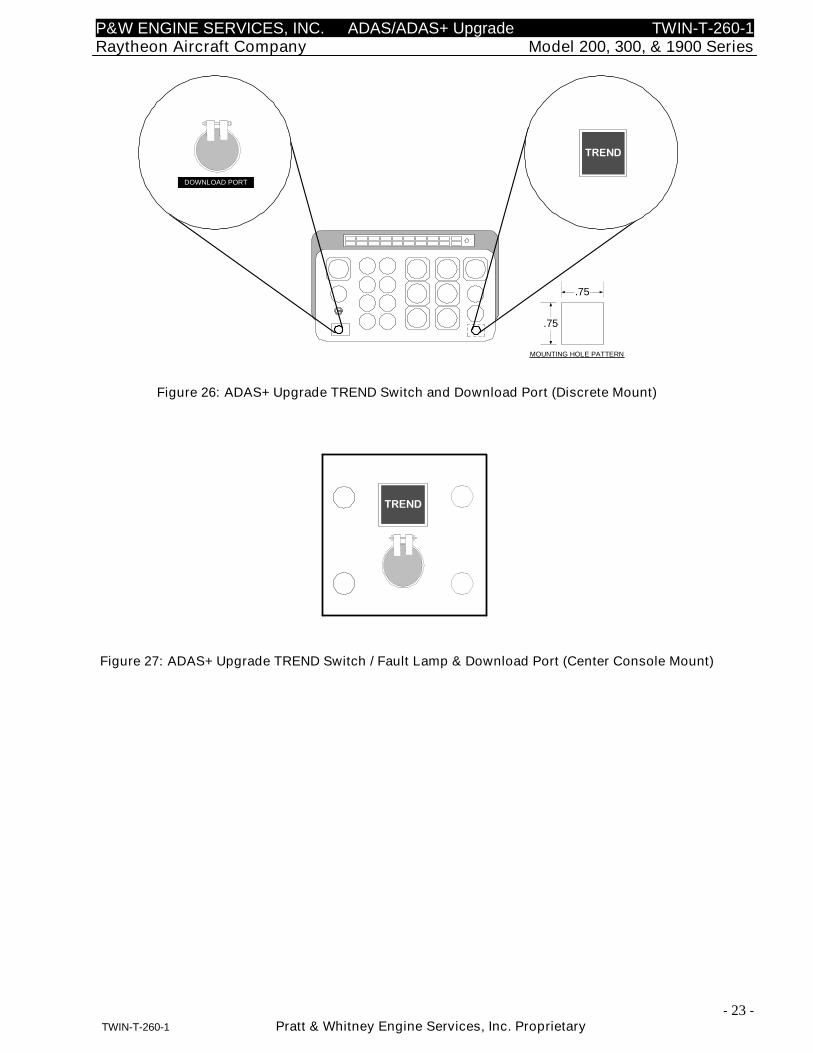
For the TREND switch / fault lamp and download port installations (Figure 24, Figure 25, Figure 26, andFigure 27), perform the following inspections:
030 Inspect TREND Switch / Fault Lamp for proper mounting.
040 Inspect Download Port for proper mounting.
P&W ENGINE SERVICES, INC. ADAS/ADAS+ Upgrade TWIN-T-260-1Raytheon Aircraft Company Model 200, 300, & 1900 Series
- 22 -TWIN-T-260-1 Pratt & Whitney Engine Services, Inc. Proprietary
TRENDENG 1
DOWNLOAD PORT
MOUNTING HOLE PATTERN
.75
.75
TRENDENG 2
.75
Figure 24: ADAS TREND Switch and Download Port (Discrete Mount)
TRENDENG 1
TRENDENG 2
ECTMPORT
Figure 25: ADAS TREND Switch / Fault Lamp & Download Port (Center Console Mount)
P&W ENGINE SERVICES, INC. ADAS/ADAS+ Upgrade TWIN-T-260-1Raytheon Aircraft Company Model 200, 300, & 1900 Series
- 23 -TWIN-T-260-1 Pratt & Whitney Engine Services, Inc. Proprietary
TREND
DOWNLOAD PORT
MOUNTING HOLE PATTERN
.75
.75
Figure 26: ADAS+ Upgrade TREND Switch and Download Port (Discrete Mount)
TREND
ECTMPORT
Figure 27: ADAS+ Upgrade TREND Switch / Fault Lamp & Download Port (Center Console Mount)
P&W ENGINE SERVICES, INC. ADAS/ADAS+ Upgrade TWIN-T-260-1Raytheon Aircraft Company Model 200, 300, & 1900 Series
- 24 -TWIN-T-260-1 Pratt & Whitney Engine Services, Inc. Proprietary
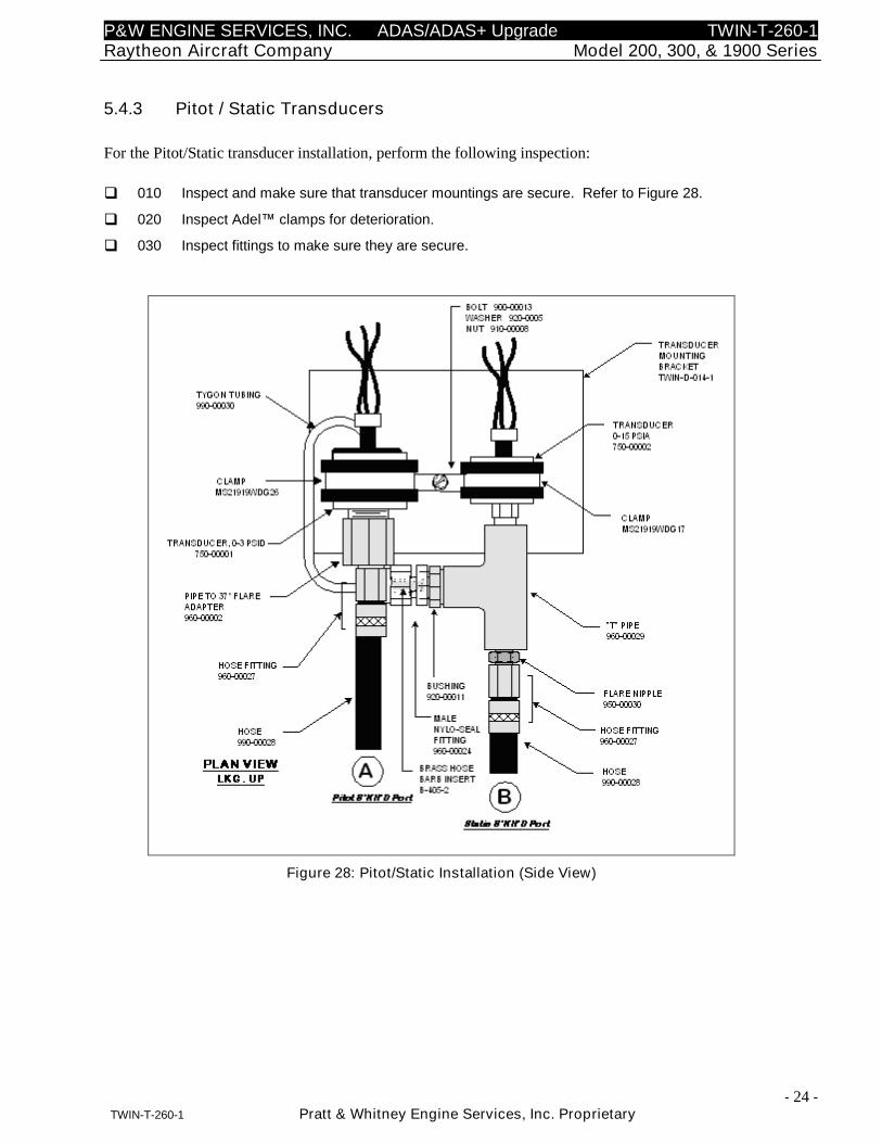
5.4.3 Pitot / Static Transducers
For the Pitot/Static transducer installation, perform the following inspection:
010 Inspect and make sure that transducer mountings are secure. Refer to Figure 28.
020 Inspect Adel™ clamps for deterioration.
030 Inspect fittings to make sure they are secure.
Figure 28: Pitot/Static Installation (Side View)
P&W ENGINE SERVICES, INC. ADAS/ADAS+ Upgrade TWIN-T-260-1Raytheon Aircraft Company Model 200, 300, & 1900 Series
- 25 -TWIN-T-260-1 Pratt & Whitney Engine Services, Inc. Proprietary
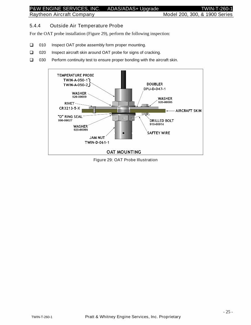
5.4.4 Outside Air Temperature Probe
For the OAT probe installation (Figure 29), perform the following inspection:
010 Inspect OAT probe assembly form proper mounting.
020 Inspect aircraft skin around OAT probe for signs of cracking.
030 Perform continuity test to ensure proper bonding with the aircraft skin.
Figure 29: OAT Probe Illustration
P&W ENGINE SERVICES, INC. ADAS/ADAS+ Upgrade TWIN-T-260-1Raytheon Aircraft Company Model 200, 300, & 1900 Series
- 26 -TWIN-T-260-1 Pratt & Whitney Engine Services, Inc. Proprietary
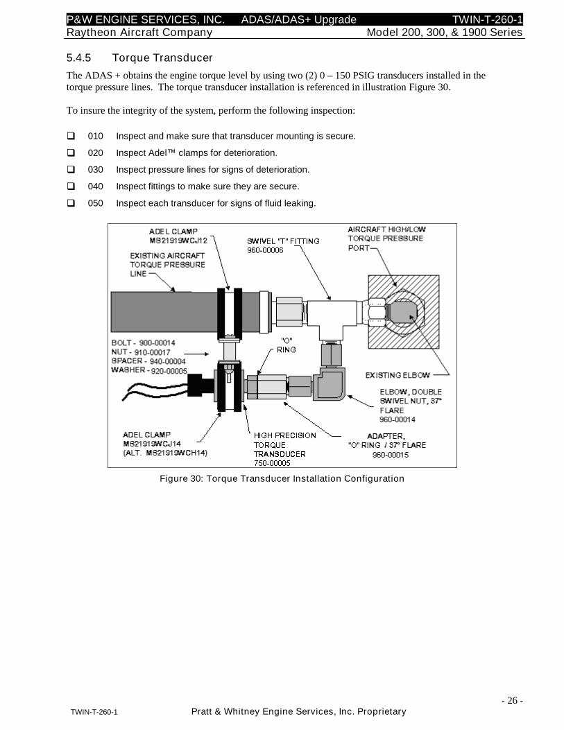
5.4.5 Torque Transducer
The ADAS + obtains the engine torque level by using two (2) 0 – 150 PSIG transducers installed in thetorque pressure lines. The torque transducer installation is referenced in illustration Figure 30.
To insure the integrity of the system, perform the following inspection:
010 Inspect and make sure that transducer mounting is secure.
020 Inspect Adel™ clamps for deterioration.
030 Inspect pressure lines for signs of deterioration.
040 Inspect fittings to make sure they are secure.
050 Inspect each transducer for signs of fluid leaking.
Figure 30: Torque Transducer Installation Configuration
P&W ENGINE SERVICES, INC. ADAS/ADAS+ Upgrade TWIN-T-260-1Raytheon Aircraft Company Model 200, 300, & 1900 Series
- 27 -TWIN-T-260-1 Pratt & Whitney Engine Services, Inc. Proprietary
6 SYSTEM TROUBLESHOOTING
When the system does not function properly (or as you expect it to operate), the first thing that you mustdo is identify and isolate the problem. When you have accomplished this, you can effectively begin toresolve the problem.
The first step in troubleshooting is to isolate each system component and ensure that each componentfunctions properly when it is run independently. Using the Monitor Link Program (MLP), you caninterrogate the system to determine which function or component may have failed. Occasionally you mayhave to replace existing components to correct the problem. Determine if the problem is in the aircraft,ADAS/ADAS+ Upgrade processor, wiring or configuration of the processor.
Ask the question, can you repeat or recreate the problem? Random events may appear to be related, butthey are not necessarily contributing factors to your problem. You may be experiencing more than oneproblem. You must isolate and solve one problem at a time. Log (document) all testing and problemisolation procedures. You may need to review and consult this document later. This will also preventyou from duplicating your testing efforts.
Once you have isolated a problem, take the necessary steps to resolve it. Refer to the problem solutionscontained in this document. If you cannot solve your system problems using this troubleshooting guide,or if the problem persists, refer to Section 4 herein and contact P&W Engine Services Help Desk.
Before contacting the Help Desk, have someone from your organization with a technical understanding ofthe ADAS/ADAS+ Upgrade Aircraft Data Acquisition System and its application provide answers to thefollowing questions:
Engine Type?
Airframe Type?
Processor Type?
Airframe Tail Number?
Processor Serial Number?
Is there a problem history?
Visual or computer indications?
Has the processor worked previously?
What activity was being performed when the failure occurred?
The ADAS/ADAS+ Upgrade will monitor and record system failures in a log that can be downloaded andreviewed. Status of the system can be obtained through the status/fault lamp.
Detailed troubleshooting for the system processor as well as for the various input channels can be foundin the topic-specific sections that follow.
P&W ENGINE SERVICES, INC. ADAS/ADAS+ Upgrade TWIN-T-260-1Raytheon Aircraft Company Model 200, 300, & 1900 Series
- 28 -TWIN-T-260-1 Pratt & Whitney Engine Services, Inc. Proprietary
6.1 System Processor
The first point of troubleshooting the ADAS/ADAS+ Upgrade is to be able to power up and communicateto the system processor.
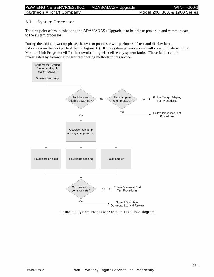
During the initial power up phase, the system processor will perform self-test and display lampindications on the cockpit fault lamp (Figure 31). If the system powers up and will communicate with theMonitor Link Program (MLP), the download log will define any system faults. These faults can beinvestigated by following the troubleshooting methods in this section.
Follow Cockpit DisplayTest Procedures
Connect the GroundStation and apply
system power.
Observe fault lamp
Fault lamp onduring power up?
Can processorcommunicate?
Observe fault lampafter system power up
Yes
Fault lamp onwhen pressed?
No
Fault lamp on solid Fault lamp flashing Fault lamp off
No
Yes Follow Processor TestProcedures
Follow Download PortTest Procedures
No
Normal Operation.Download Log and Review
Yes
Figure 31: System Processor Start Up Test Flow Diagram
P&W ENGINE SERVICES, INC. ADAS/ADAS+ Upgrade TWIN-T-260-1Raytheon Aircraft Company Model 200, 300, & 1900 Series
- 29 -TWIN-T-260-1 Pratt & Whitney Engine Services, Inc. Proprietary
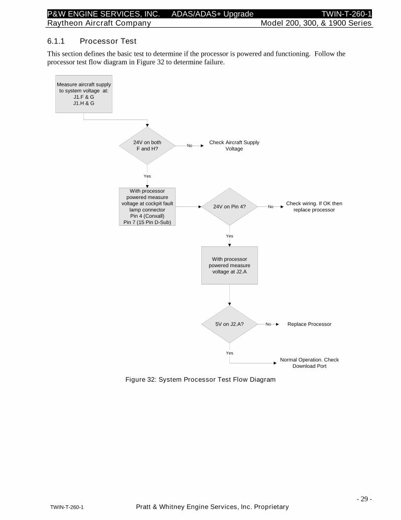
6.1.1 Processor Test
This section defines the basic test to determine if the processor is powered and functioning. Follow theprocessor test flow diagram in Figure 32 to determine failure.
Check Aircraft SupplyVoltage
Measure aircraft supplyto system voltage at:
J1.F & GJ1.H & G
24V on bothF and H?
5V on J2.A?
With processorpowered measure
voltage at cockpit faultlamp connectorPin 4 (Conxall)
Pin 7 (15 Pin D-Sub)
Yes
No
Check wiring. If OK thenreplace processor
Replace ProcessorNo
Normal Operation. CheckDownload Port
Yes
24V on Pin 4? No
With processorpowered measure
voltage at J2.A
Yes
Figure 32: System Processor Test Flow Diagram
P&W ENGINE SERVICES, INC. ADAS/ADAS+ Upgrade TWIN-T-260-1Raytheon Aircraft Company Model 200, 300, & 1900 Series
- 30 -TWIN-T-260-1 Pratt & Whitney Engine Services, Inc. Proprietary
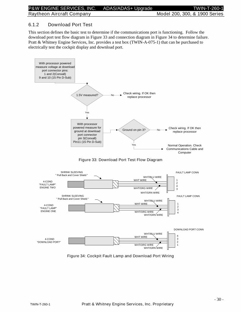
6.1.2 Download Port Test
This section defines the basic test to determine if the communications port is functioning. Follow thedownload port test flow diagram in Figure 33 and connection diagram in Figure 34 to determine failure.Pratt & Whitney Engine Services, Inc. provides a test box (TWIN-A-075-1) that can be purchased toelectrically test the cockpit display and download port.
With processor poweredmeasure voltage at download
port connector pins:1 and 2(Conxall)
9 and 10 (15 Pin D-Sub)
1.5V measured?
With processorpowered measure forground at download
port connectorpin 3(Conxall)
Pin11 (15 Pin D-Sub)
Yes
No
Check wiring. If OK thenreplace processor
Normal Operation. CheckCommunications Cable and
Computer
Ground on pin 3? No
Yes
Check wiring. If OK thenreplace processor
Figure 33: Download Port Test Flow Diagram
FAULT LAMP CONN
WHT WIREWHT/BLU WIRE
WHT/GRN WIREWHT/ORG WIRE
SHRINK SLEEVING" Pull Back and Cover Shield "
4-COND"FAULT LAMP"ENGINE ONE
4-COND"DOWNLOAD PORT"
1234
4321
WHT WIRE
WHT/BLU WIRE
WHT/GRN WIREWHT/ORG WIRE
DOWNLOAD PORT CONN
FAULT LAMP CONN
WHT WIREWHT/BLU WIRE
WHT/GRN WIRE
WHT/ORG WIRE
SHRINK SLEEVING" Pull Back and Cover Shield "
4-COND"FAULT LAMP"ENGINE TWO
1243
Figure 34: Cockpit Fault Lamp and Download Port Wiring
P&W ENGINE SERVICES, INC. ADAS/ADAS+ Upgrade TWIN-T-260-1Raytheon Aircraft Company Model 200, 300, & 1900 Series
- 31 -TWIN-T-260-1 Pratt & Whitney Engine Services, Inc. Proprietary
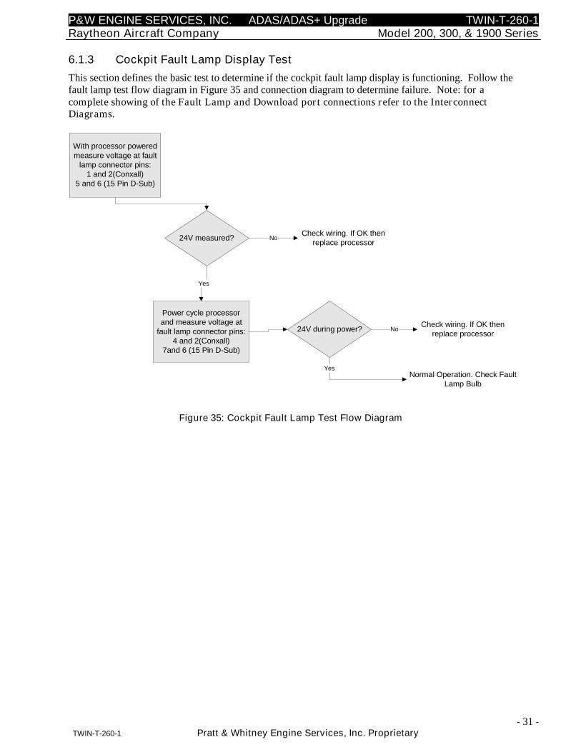
6.1.3 Cockpit Fault Lamp Display Test
This section defines the basic test to determine if the cockpit fault lamp display is functioning. Follow thefault lamp test flow diagram in Figure 35 and connection diagram to determine failure. Note: for acomplete showing of the Fault Lamp and Download port connections refer to the InterconnectDiagrams.
With processor poweredmeasure voltage at fault
lamp connector pins:1 and 2(Conxall)
5 and 6 (15 Pin D-Sub)
24V measured?
Power cycle processorand measure voltage at
fault lamp connector pins:4 and 2(Conxall)
7and 6 (15 Pin D-Sub)
Yes
No
Check wiring. If OK thenreplace processor
Normal Operation. Check FaultLamp Bulb
24V during power? No
Yes
Check wiring. If OK thenreplace processor
Figure 35: Cockpit Fault Lamp Test Flow Diagram
P&W ENGINE SERVICES, INC. ADAS/ADAS+ Upgrade TWIN-T-260-1Raytheon Aircraft Company Model 200, 300, & 1900 Series
- 32 -TWIN-T-260-1 Pratt & Whitney Engine Services, Inc. Proprietary
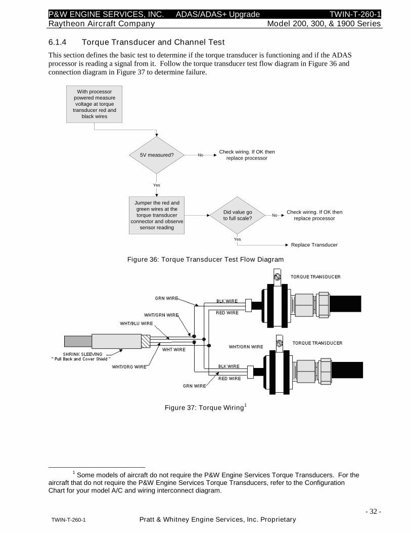
6.1.4 Torque Transducer and Channel Test
This section defines the basic test to determine if the torque transducer is functioning and if the ADASprocessor is reading a signal from it. Follow the torque transducer test flow diagram in Figure 36 andconnection diagram in Figure 37 to determine failure.
With processorpowered measurevoltage at torque
transducer red andblack wires
5V measured?
Jumper the red andgreen wires at thetorque transducer
connector and observesensor reading
Yes
No
Check wiring. If OK thenreplace processor
Replace Transducer
Did value goto full scale?
No
Yes
Check wiring. If OK thenreplace processor
Figure 36: Torque Transducer Test Flow Diagram
Figure 37: Torque Wiring1
1Some models of aircraft do not require the P&W Engine Services Torque Transducers. For the
aircraft that do not require the P&W Engine Services Torque Transducers, refer to the ConfigurationChart for your model A/C and wiring interconnect diagram.
P&W ENGINE SERVICES, INC. ADAS/ADAS+ Upgrade TWIN-T-260-1Raytheon Aircraft Company Model 200, 300, & 1900 Series
- 33 -TWIN-T-260-1 Pratt & Whitney Engine Services, Inc. Proprietary
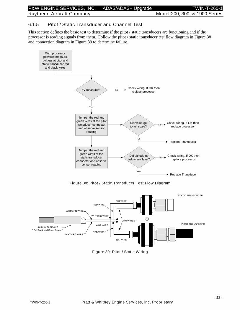
6.1.5 Pitot / Static Transducer and Channel Test
This section defines the basic test to determine if the pitot / static transducers are functioning and if theprocessor is reading signals from them. Follow the pitot / static transducer test flow diagram in Figure 38and connection diagram in Figure 39 to determine failure.
With processorpowered measurevoltage at pitot and
static transducer redand black wires
5V measured?
Jumper the red andgreen wires at the pitottransducer connectorand observe sensor
reading
Yes
No
Check wiring. If OK thenreplace processor
Replace Transducer
Did value goto full scale?
No
Yes
Check wiring. If OK thenreplace processor
Jumper the red andgreen wires at thestatic transducer
connector and observesensor reading
Check wiring. If OK thenreplace processor
Replace Transducer
Did altitude gobelow sea level?
No
Yes
Figure 38: Pitot / Static Transducer Test Flow Diagram
STATIC TRANSDUCER
PITOT TRANSDUCER
SHRINK SLEEVING" Pull Back and Cover Shield "
GRN WIRES
BLK WIRE
BLK WIRE
RED WIRE
RED WIRE
WHT WIRE
WHT/BLU WIRE
WHT/GRN WIRE
WHT/ORG WIRE
Figure 39: Pitot / Static Wiring
P&W ENGINE SERVICES, INC. ADAS/ADAS+ Upgrade TWIN-T-260-1Raytheon Aircraft Company Model 200, 300, & 1900 Series
- 34 -TWIN-T-260-1 Pratt & Whitney Engine Services, Inc. Proprietary
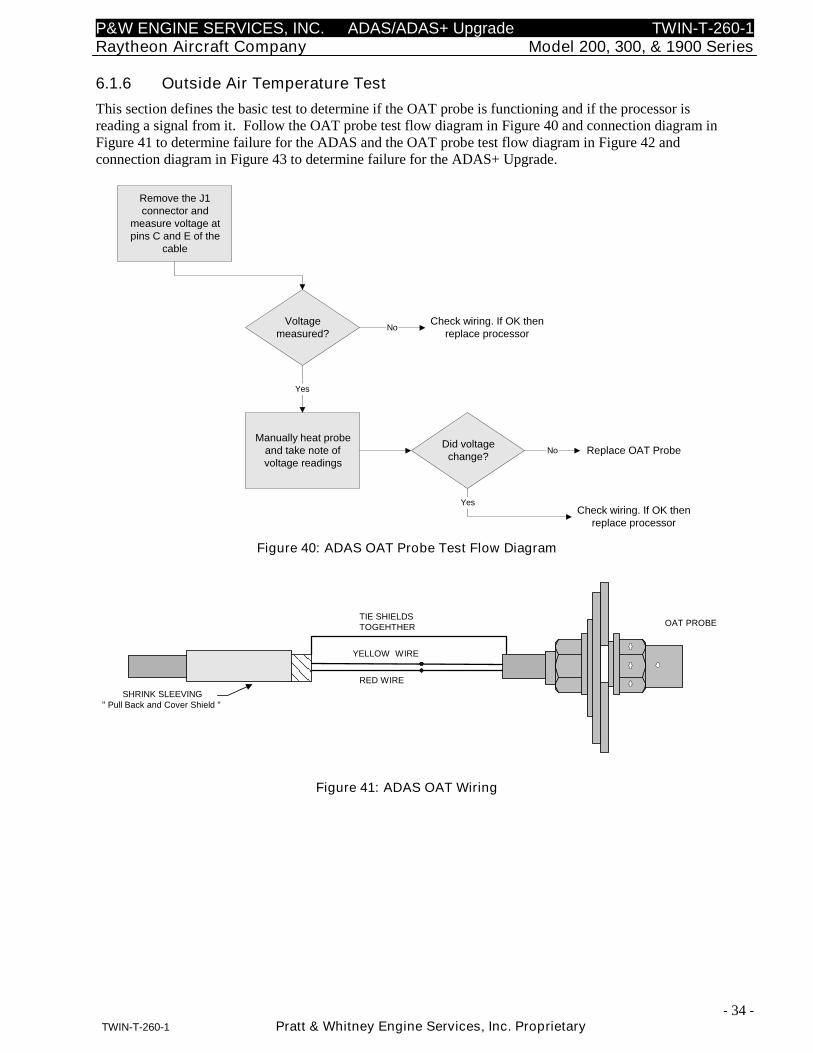
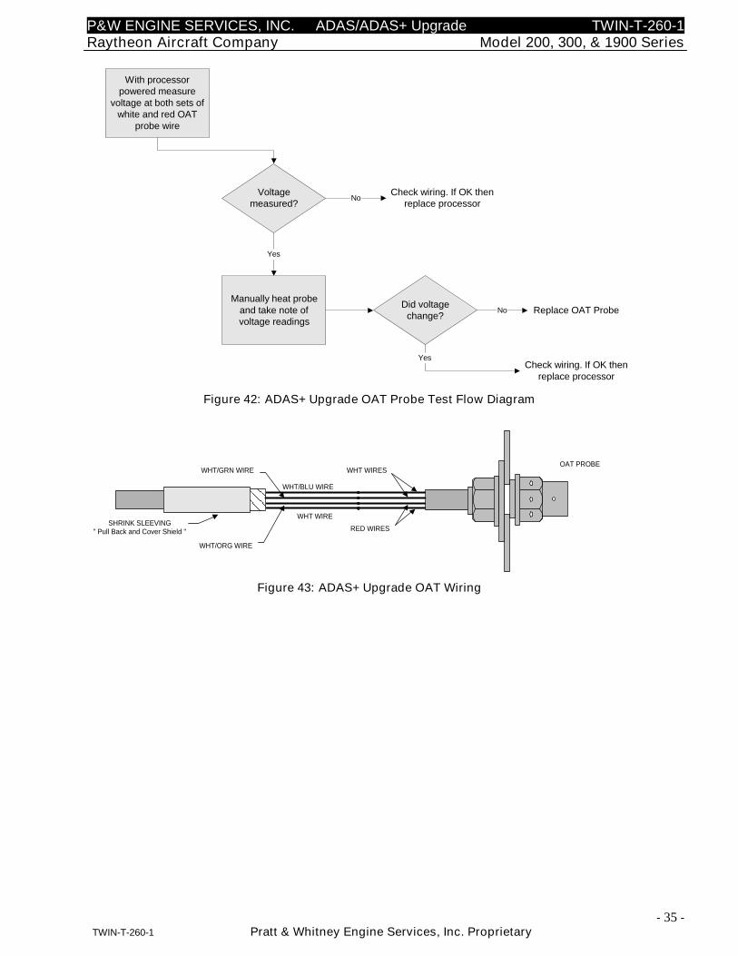
6.1.6 Outside Air Temperature Test
This section defines the basic test to determine if the OAT probe is functioning and if the processor isreading a signal from it. Follow the OAT probe test flow diagram in Figure 40 and connection diagram inFigure 41 to determine failure for the ADAS and the OAT probe test flow diagram in Figure 42 andconnection diagram in Figure 43 to determine failure for the ADAS+ Upgrade.
Remove the J1connector and
measure voltage atpins C and E of the
cable
Voltagemeasured?
Manually heat probeand take note ofvoltage readings
Yes
No
Check wiring. If OK thenreplace processor
Replace OAT ProbeDid voltage
change?No
Yes
Check wiring. If OK thenreplace processor
Figure 40: ADAS OAT Probe Test Flow Diagram
OAT PROBE
SHRINK SLEEVING" Pull Back and Cover Shield "
RED WIRE
YELLOW WIRE
TIE SHIELDSTOGEHTHER
Figure 41: ADAS OAT Wiring
P&W ENGINE SERVICES, INC. ADAS/ADAS+ Upgrade TWIN-T-260-1Raytheon Aircraft Company Model 200, 300, & 1900 Series
- 35 -TWIN-T-260-1 Pratt & Whitney Engine Services, Inc. Proprietary
With processorpowered measure
voltage at both sets ofwhite and red OAT
probe wire
Voltagemeasured?
Manually heat probeand take note ofvoltage readings
Yes
No
Check wiring. If OK thenreplace processor
Replace OAT ProbeDid voltage
change?No
Yes
Check wiring. If OK thenreplace processor
Figure 42: ADAS+ Upgrade OAT Probe Test Flow Diagram
OAT PROBE
SHRINK SLEEVING" Pull Back and Cover Shield "
WHT WIRES
RED WIRES
WHT WIRE
WHT/BLU WIRE
WHT/GRN WIRE
WHT/ORG WIRE
Figure 43: ADAS+ Upgrade OAT Wiring
P&W ENGINE SERVICES, INC. ADAS/ADAS+ Upgrade TWIN-T-260-1Raytheon Aircraft Company Model 200, 300, & 1900 Series
- 36 -TWIN-T-260-1 Pratt & Whitney Engine Services, Inc. Proprietary
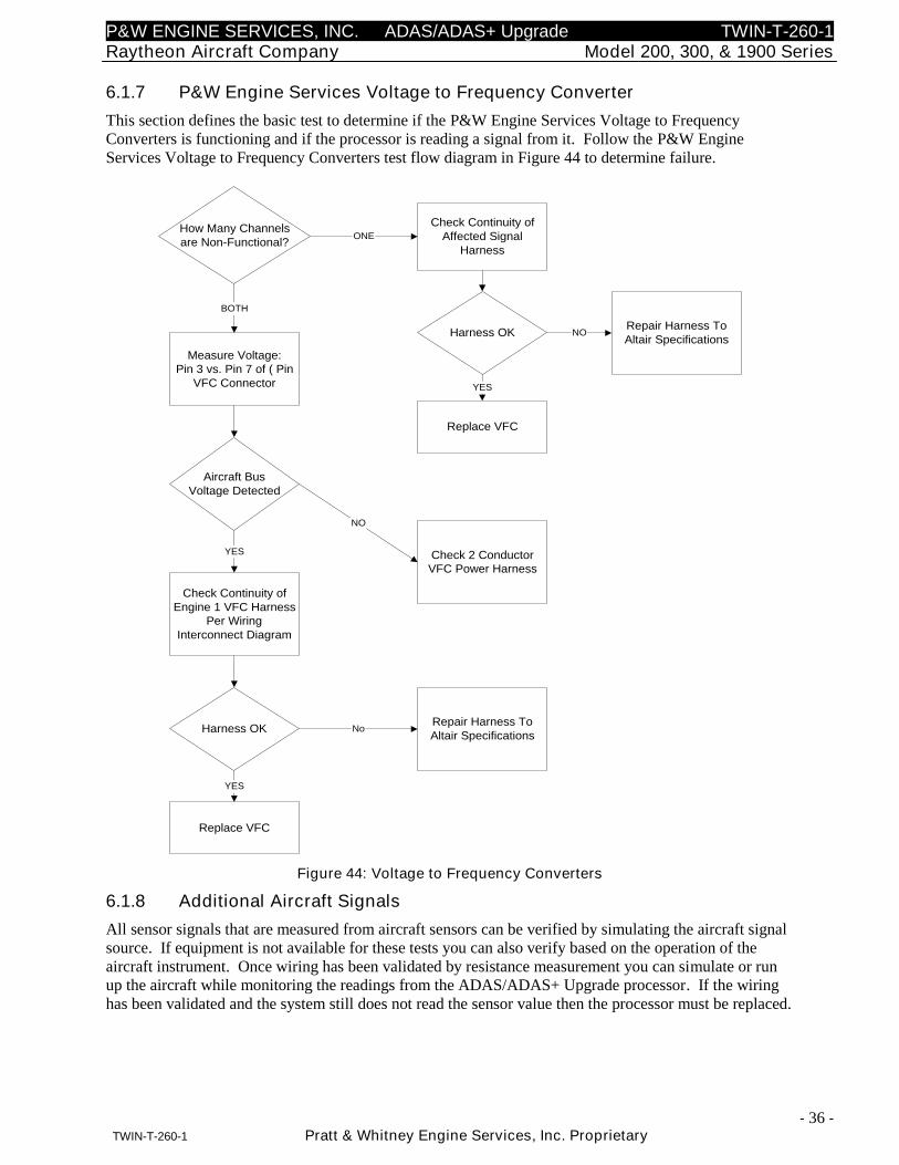
6.1.7 P&W Engine Services Voltage to Frequency Converter
This section defines the basic test to determine if the P&W Engine Services Voltage to FrequencyConverters is functioning and if the processor is reading a signal from it. Follow the P&W EngineServices Voltage to Frequency Converters test flow diagram in Figure 44 to determine failure.
How Many Channelsare Non-Functional?
Check Continuity ofAffected Signal
Harness
ONE
Measure Voltage:Pin 3 vs. Pin 7 of ( Pin
VFC Connector
BOTH
Harness OKRepair Harness ToAltair Specifications
NO
Replace VFC
YES
Aircraft BusVoltage Detected
Check 2 ConductorVFC Power Harness
Check Continuity ofEngine 1 VFC Harness
Per WiringInterconnect Diagram
YES
Harness OKRepair Harness ToAltair Specifications
No
Replace VFC
YES
NO
Figure 44: Voltage to Frequency Converters
6.1.8 Additional Aircraft Signals
All sensor signals that are measured from aircraft sensors can be verified by simulating the aircraft signalsource. If equipment is not available for these tests you can also verify based on the operation of theaircraft instrument. Once wiring has been validated by resistance measurement you can simulate or runup the aircraft while monitoring the readings from the ADAS/ADAS+ Upgrade processor. If the wiringhas been validated and the system still does not read the sensor value then the processor must be replaced.
P&W ENGINE SERVICES, INC. ADAS/ADAS+ Upgrade TWIN-T-260-1Raytheon Aircraft Company Model 200, 300, & 1900 Series
- 37 -TWIN-T-260-1 Pratt & Whitney Engine Services, Inc. Proprietary
7 REMOVAL AND REPLACEMENT INFORMATION
7.1 Processor Removal/Replacement
NOTE: Insure that power is removed from the aircraft and the battery is disconnected
010 Disconnect the J1, J2, J3, and Comm wiring harnesses from the processor.
020 Disconnect the ground strap between the processor mounting stud and the aircraft chassis.
030 Disassemble the ADAS/ADAS+ Upgrade processor from the mounting bracket shown inFigure 23.
040 Assemble the ADAS/ADAS+ Upgrade processor to the mounting bracket shown in Figure 23.Ensure that the processor does not interfere with wiring or controls.
INSTALLATION CAUTION:
Excessive torque on the processor-mounting studs can deform the shock mounts. Thelocking nut should be tightened to the point of contact with the shock mount.
050 Install ground strap between one of the processor mounting studs and the aircraft chassis.
060 Connect wiring harnesses J1, J2, J3, and Comm to the processor.
070 Perform configuration and calibration per instructions in ADAS/ADAS+ Upgrade InstallationManual TWIN-I-010-1, System Configuration and Calibration.
7.2 TREND Switch Removal/Replacement
010 Insure that power is removed from the aircraft and the battery is disconnected.
020 Disconnect TREND Switch ConXall™ connector under instrument panel.
030 Remove TREND Switch by squeezing locking springs on sides of switch and pushing theswitch thru the hole in the instrument panel.
040 Replace TREND switch and reconnect ConXall™ connector.
P&W ENGINE SERVICES, INC. ADAS/ADAS+ Upgrade TWIN-T-260-1Raytheon Aircraft Company Model 200, 300, & 1900 Series
- 38 -TWIN-T-260-1 Pratt & Whitney Engine Services, Inc. Proprietary
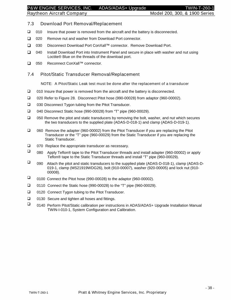
7.3 Download Port Removal/Replacement
010 Insure that power is removed from the aircraft and the battery is disconnected.
020 Remove nut and washer from Download Port connector.
030 Disconnect Download Port ConXall™ connector. Remove Download Port.
040 Install Download Port into Instrument Panel and secure in place with washer and nut usingLoctite® Blue on the threads of the download port.
050 Reconnect ConXall™ connector.
7.4 Pitot/Static Transducer Removal/Replacement
NOTE: A Pitot/Static Leak test must be done after the replacement of a transducer
010 Insure that power is removed from the aircraft and the battery is disconnected.
020 Refer to Figure 28. Disconnect Pitot hose (990-00028) from adaptor (960-00002).
030 Disconnect Tygon tubing from the Pitot Transducer.
040 Disconnect Static hose (990-00028) from “T” pipe (960-00029).
050 Remove the pitot and static transducers by removing the bolt, washer, and nut which securesthe two transducers to the supplied plate (ADAS-D-018-1) and clamp (ADAS-D-019-1).
060 Remove the adapter (960-00002) from the Pitot Transducer if you are replacing the PitotTransducer or the “T” pipe (960-00029) from the Static Transducer if you are replacing theStatic Transducer.
070 Replace the appropriate transducer as necessary.
080 Apply Teflon® tape to the Pitot Transducer threads and install adapter (960-00002) or applyTeflon® tape to the Static Transducer threads and install “T” pipe (960-00029).
090 Attach the pitot and static transducers to the supplied plate (ADAS-D-018-1), clamp (ADAS-D-019-1, clamp (MS21919WDG26), bolt (910-00007), washer (920-00005) and lock nut (910-00008).
0100 Connect the Pitot hose (990-00028) to the adaptor (960-00002).
0110 Connect the Static hose (990-00028) to the “T” pipe (960-00029).
0120 Connect Tygon tubing to the Pitot Transducer.
0130 Secure and tighten all hoses and fittings.
0140 Perform Pitot/Static calibration per instructions in ADAS/ADAS+ Upgrade Installation ManualTWIN-I-010-1, System Configuration and Calibration.
P&W ENGINE SERVICES, INC. ADAS/ADAS+ Upgrade TWIN-T-260-1Raytheon Aircraft Company Model 200, 300, & 1900 Series
- 39 -TWIN-T-260-1 Pratt & Whitney Engine Services, Inc. Proprietary
7.5 OAT Removal/Replacement
010 Insure that power is removed from the aircraft and the battery is disconnected.
020 Remove safety wire from OAT jam nut (TWIN-D-061-1).
030 Remove OAT jam nut.
040 Remove temperature probe from hole.
050 Insert new temperature probe into the hole and install washers (920-00009), “O” ring (990-00027) and jam nut (TWIN-D-061-1).
060 Tighten and safety wire the jam nut to the bolt (910-00007).
070 Apply a bead of sealant (ProSeal PR1422 or equivalent) around edge of doubler afterinstallation and smooth to produce a filleted profile.
080 Apply a bead of sealant (ProSeal PR1422 or equivalent) around the inner and outer edges ofthe OAT probe after installation and smooth to produce a filleted profile.
090 Perform OAT calibration per instructions in ADAS/ADAS+ Upgrade Installation Manual TWIN-I-010-1, System Configuration and Calibration.
7.6 Torque Transducer Removal/Replacement
NOTE: A Leak test must be done after the replacement of a transducer
010 Insure that power is removed from the aircraft and the battery is disconnected.
020 Referring to Figure 30, remove the “T” swivel (960-00012) from the adapter fitting (960-00015).
030 Remove the adapter (960-00015) from the transducer.
040 Remove the transducer from the clamp (MS21919WCJ14).
050 Replace the transducer.
060 Using Teflon® tape, install and torque the 0 - 150 PSIG transducers (750-00005) into theadapter fitting (960-00015).
070 Connect the torque transducer / adapter fitting assembly to the “T” swivel (960-00012).
080 Secure / torque all lines and fittings per the manufacturer’s recommendations.
090 Perform Torque calibration per instructions in ADAS/ADAS+ Upgrade Installation ManualTWIN-I-010-1, System Configuration and Calibration.
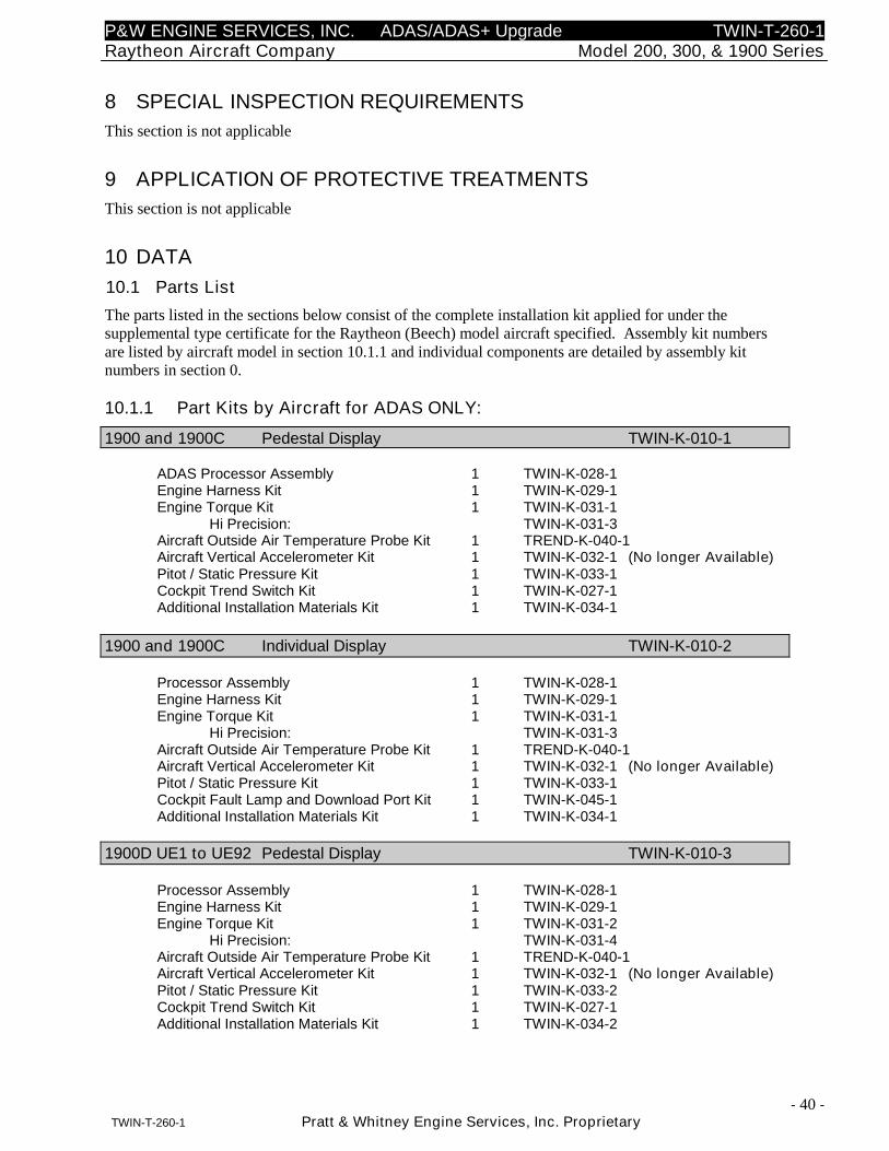
P&W ENGINE SERVICES, INC. ADAS/ADAS+ Upgrade TWIN-T-260-1Raytheon Aircraft Company Model 200, 300, & 1900 Series
- 40 -TWIN-T-260-1 Pratt & Whitney Engine Services, Inc. Proprietary
8 SPECIAL INSPECTION REQUIREMENTS
This section is not applicable
9 APPLICATION OF PROTECTIVE TREATMENTS
This section is not applicable
10 DATA
10.1 Parts List
The parts listed in the sections below consist of the complete installation kit applied for under thesupplemental type certificate for the Raytheon (Beech) model aircraft specified. Assembly kit numbersare listed by aircraft model in section 10.1.1 and individual components are detailed by assembly kitnumbers in section 0.
10.1.1 Part Kits by Aircraft for ADAS ONLY:
1900 and 1900C Pedestal Display TWIN-K-010-1
ADAS Processor Assembly 1 TWIN-K-028-1Engine Harness Kit 1 TWIN-K-029-1Engine Torque Kit 1 TWIN-K-031-1
Hi Precision: TWIN-K-031-3Aircraft Outside Air Temperature Probe Kit 1 TREND-K-040-1Aircraft Vertical Accelerometer Kit 1 TWIN-K-032-1 (No longer Available)Pitot / Static Pressure Kit 1 TWIN-K-033-1Cockpit Trend Switch Kit 1 TWIN-K-027-1Additional Installation Materials Kit 1 TWIN-K-034-1
1900 and 1900C Individual Display TWIN-K-010-2
Processor Assembly 1 TWIN-K-028-1Engine Harness Kit 1 TWIN-K-029-1Engine Torque Kit 1 TWIN-K-031-1
Hi Precision: TWIN-K-031-3Aircraft Outside Air Temperature Probe Kit 1 TREND-K-040-1Aircraft Vertical Accelerometer Kit 1 TWIN-K-032-1 (No longer Available)Pitot / Static Pressure Kit 1 TWIN-K-033-1Cockpit Fault Lamp and Download Port Kit 1 TWIN-K-045-1Additional Installation Materials Kit 1 TWIN-K-034-1
1900D UE1 to UE92 Pedestal Display TWIN-K-010-3
Processor Assembly 1 TWIN-K-028-1Engine Harness Kit 1 TWIN-K-029-1Engine Torque Kit 1 TWIN-K-031-2
Hi Precision: TWIN-K-031-4Aircraft Outside Air Temperature Probe Kit 1 TREND-K-040-1Aircraft Vertical Accelerometer Kit 1 TWIN-K-032-1 (No longer Available)Pitot / Static Pressure Kit 1 TWIN-K-033-2Cockpit Trend Switch Kit 1 TWIN-K-027-1Additional Installation Materials Kit 1 TWIN-K-034-2
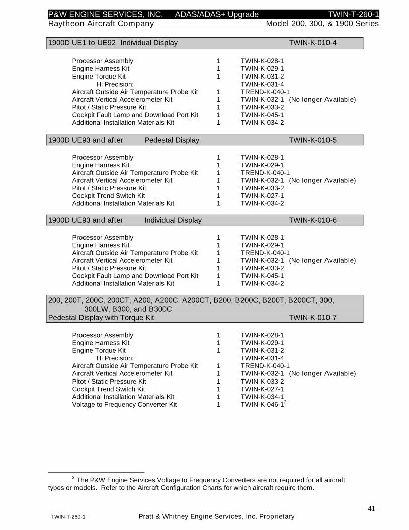
P&W ENGINE SERVICES, INC. ADAS/ADAS+ Upgrade TWIN-T-260-1Raytheon Aircraft Company Model 200, 300, & 1900 Series
- 41 -TWIN-T-260-1 Pratt & Whitney Engine Services, Inc. Proprietary
1900D UE1 to UE92 Individual Display TWIN-K-010-4
Processor Assembly 1 TWIN-K-028-1Engine Harness Kit 1 TWIN-K-029-1Engine Torque Kit 1 TWIN-K-031-2
Hi Precision: TWIN-K-031-4Aircraft Outside Air Temperature Probe Kit 1 TREND-K-040-1Aircraft Vertical Accelerometer Kit 1 TWIN-K-032-1 (No longer Available)Pitot / Static Pressure Kit 1 TWIN-K-033-2Cockpit Fault Lamp and Download Port Kit 1 TWIN-K-045-1Additional Installation Materials Kit 1 TWIN-K-034-2
1900D UE93 and after Pedestal Display TWIN-K-010-5
Processor Assembly 1 TWIN-K-028-1Engine Harness Kit 1 TWIN-K-029-1Aircraft Outside Air Temperature Probe Kit 1 TREND-K-040-1Aircraft Vertical Accelerometer Kit 1 TWIN-K-032-1 (No longer Available)Pitot / Static Pressure Kit 1 TWIN-K-033-2Cockpit Trend Switch Kit 1 TWIN-K-027-1Additional Installation Materials Kit 1 TWIN-K-034-2
1900D UE93 and after Individual Display TWIN-K-010-6
Processor Assembly 1 TWIN-K-028-1Engine Harness Kit 1 TWIN-K-029-1Aircraft Outside Air Temperature Probe Kit 1 TREND-K-040-1Aircraft Vertical Accelerometer Kit 1 TWIN-K-032-1 (No longer Available)Pitot / Static Pressure Kit 1 TWIN-K-033-2Cockpit Fault Lamp and Download Port Kit 1 TWIN-K-045-1Additional Installation Materials Kit 1 TWIN-K-034-2
200, 200T, 200C, 200CT, A200, A200C, A200CT, B200, B200C, B200T, B200CT, 300,300LW, B300, and B300C
Pedestal Display with Torque Kit TWIN-K-010-7
Processor Assembly 1 TWIN-K-028-1Engine Harness Kit 1 TWIN-K-029-1Engine Torque Kit 1 TWIN-K-031-2
Hi Precision: TWIN-K-031-4Aircraft Outside Air Temperature Probe Kit 1 TREND-K-040-1Aircraft Vertical Accelerometer Kit 1 TWIN-K-032-1 (No longer Available)Pitot / Static Pressure Kit 1 TWIN-K-033-2Cockpit Trend Switch Kit 1 TWIN-K-027-1Additional Installation Materials Kit 1 TWIN-K-034-1Voltage to Frequency Converter Kit 1 TWIN-K-046-1
2
2The P&W Engine Services Voltage to Frequency Converters are not required for all aircraft
types or models. Refer to the Aircraft Configuration Charts for which aircraft require them.
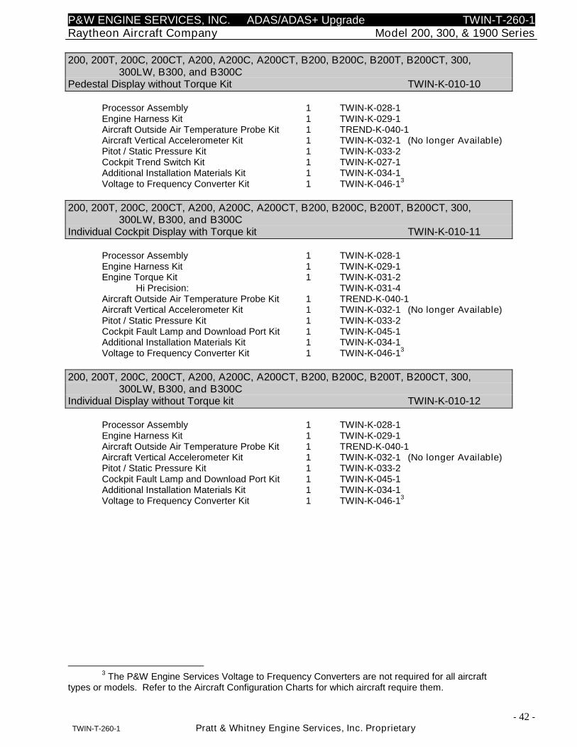
P&W ENGINE SERVICES, INC. ADAS/ADAS+ Upgrade TWIN-T-260-1Raytheon Aircraft Company Model 200, 300, & 1900 Series
- 42 -TWIN-T-260-1 Pratt & Whitney Engine Services, Inc. Proprietary
200, 200T, 200C, 200CT, A200, A200C, A200CT, B200, B200C, B200T, B200CT, 300,300LW, B300, and B300C
Pedestal Display without Torque Kit TWIN-K-010-10
Processor Assembly 1 TWIN-K-028-1Engine Harness Kit 1 TWIN-K-029-1Aircraft Outside Air Temperature Probe Kit 1 TREND-K-040-1Aircraft Vertical Accelerometer Kit 1 TWIN-K-032-1 (No longer Available)Pitot / Static Pressure Kit 1 TWIN-K-033-2Cockpit Trend Switch Kit 1 TWIN-K-027-1Additional Installation Materials Kit 1 TWIN-K-034-1Voltage to Frequency Converter Kit 1 TWIN-K-046-1
3
200, 200T, 200C, 200CT, A200, A200C, A200CT, B200, B200C, B200T, B200CT, 300,300LW, B300, and B300C
Individual Cockpit Display with Torque kit TWIN-K-010-11
Processor Assembly 1 TWIN-K-028-1Engine Harness Kit 1 TWIN-K-029-1Engine Torque Kit 1 TWIN-K-031-2
Hi Precision: TWIN-K-031-4Aircraft Outside Air Temperature Probe Kit 1 TREND-K-040-1Aircraft Vertical Accelerometer Kit 1 TWIN-K-032-1 (No longer Available)Pitot / Static Pressure Kit 1 TWIN-K-033-2Cockpit Fault Lamp and Download Port Kit 1 TWIN-K-045-1Additional Installation Materials Kit 1 TWIN-K-034-1Voltage to Frequency Converter Kit 1 TWIN-K-046-1
3
200, 200T, 200C, 200CT, A200, A200C, A200CT, B200, B200C, B200T, B200CT, 300,300LW, B300, and B300C
Individual Display without Torque kit TWIN-K-010-12
Processor Assembly 1 TWIN-K-028-1Engine Harness Kit 1 TWIN-K-029-1Aircraft Outside Air Temperature Probe Kit 1 TREND-K-040-1Aircraft Vertical Accelerometer Kit 1 TWIN-K-032-1 (No longer Available)Pitot / Static Pressure Kit 1 TWIN-K-033-2Cockpit Fault Lamp and Download Port Kit 1 TWIN-K-045-1Additional Installation Materials Kit 1 TWIN-K-034-1Voltage to Frequency Converter Kit 1 TWIN-K-046-1
3
3The P&W Engine Services Voltage to Frequency Converters are not required for all aircraft
types or models. Refer to the Aircraft Configuration Charts for which aircraft require them.
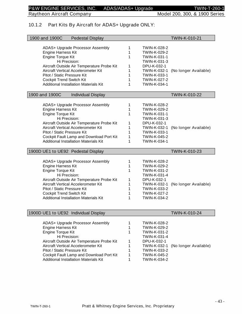
P&W ENGINE SERVICES, INC. ADAS/ADAS+ Upgrade TWIN-T-260-1Raytheon Aircraft Company Model 200, 300, & 1900 Series
- 43 -TWIN-T-260-1 Pratt & Whitney Engine Services, Inc. Proprietary
10.1.2 Part Kits By Aircraft for ADAS+ Upgrade ONLY:
1900 and 1900C Pedestal Display TWIN-K-010-21
ADAS+ Upgrade Processor Assembly 1 TWIN-K-028-2Engine Harness Kit 1 TWIN-K-029-2Engine Torque Kit 1 TWIN-K-031-1
Hi Precision: TWIN-K-031-3Aircraft Outside Air Temperature Probe Kit 1 DPU-K-032-1Aircraft Vertical Accelerometer Kit 1 TWIN-K-032-1 (No longer Available)Pitot / Static Pressure Kit 1 TWIN-K-033-1Cockpit Trend Switch Kit 1 TWIN-K-027-2Additional Installation Materials Kit 1 TWIN-K-034-1
1900 and 1900C Individual Display TWIN-K-010-22
ADAS+ Upgrade Processor Assembly 1 TWIN-K-028-2Engine Harness Kit 1 TWIN-K-029-2Engine Torque Kit 1 TWIN-K-031-1
Hi Precision: TWIN-K-031-3Aircraft Outside Air Temperature Probe Kit 1 DPU-K-032-1Aircraft Vertical Accelerometer Kit 1 TWIN-K-032-1 (No longer Available)Pitot / Static Pressure Kit 1 TWIN-K-033-1Cockpit Fault Lamp and Download Port Kit 1 TWIN-K-045-2Additional Installation Materials Kit 1 TWIN-K-034-1
1900D UE1 to UE92 Pedestal Display TWIN-K-010-23
ADAS+ Upgrade Processor Assembly 1 TWIN-K-028-2Engine Harness Kit 1 TWIN-K-029-2Engine Torque Kit 1 TWIN-K-031-2
Hi Precision: TWIN-K-031-4Aircraft Outside Air Temperature Probe Kit 1 DPU-K-032-1Aircraft Vertical Accelerometer Kit 1 TWIN-K-032-1 (No longer Available)Pitot / Static Pressure Kit 1 TWIN-K-033-2Cockpit Trend Switch Kit 1 TWIN-K-027-2Additional Installation Materials Kit 1 TWIN-K-034-2
1900D UE1 to UE92 Individual Display TWIN-K-010-24
ADAS+ Upgrade Processor Assembly 1 TWIN-K-028-2Engine Harness Kit 1 TWIN-K-029-2Engine Torque Kit 1 TWIN-K-031-2
Hi Precision: TWIN-K-031-4Aircraft Outside Air Temperature Probe Kit 1 DPU-K-032-1Aircraft Vertical Accelerometer Kit 1 TWIN-K-032-1 (No longer Available)Pitot / Static Pressure Kit 1 TWIN-K-033-2Cockpit Fault Lamp and Download Port Kit 1 TWIN-K-045-2Additional Installation Materials Kit 1 TWIN-K-034-2
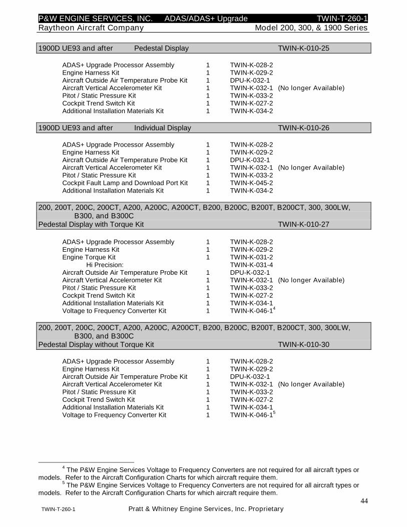
P&W ENGINE SERVICES, INC. ADAS/ADAS+ Upgrade TWIN-T-260-1Raytheon Aircraft Company Model 200, 300, & 1900 Series
44TWIN-T-260-1 Pratt & Whitney Engine Services, Inc. Proprietary
1900D UE93 and after Pedestal Display TWIN-K-010-25
ADAS+ Upgrade Processor Assembly 1 TWIN-K-028-2Engine Harness Kit 1 TWIN-K-029-2Aircraft Outside Air Temperature Probe Kit 1 DPU-K-032-1Aircraft Vertical Accelerometer Kit 1 TWIN-K-032-1 (No longer Available)Pitot / Static Pressure Kit 1 TWIN-K-033-2Cockpit Trend Switch Kit 1 TWIN-K-027-2Additional Installation Materials Kit 1 TWIN-K-034-2
1900D UE93 and after Individual Display TWIN-K-010-26
ADAS+ Upgrade Processor Assembly 1 TWIN-K-028-2Engine Harness Kit 1 TWIN-K-029-2Aircraft Outside Air Temperature Probe Kit 1 DPU-K-032-1Aircraft Vertical Accelerometer Kit 1 TWIN-K-032-1 (No longer Available)Pitot / Static Pressure Kit 1 TWIN-K-033-2Cockpit Fault Lamp and Download Port Kit 1 TWIN-K-045-2Additional Installation Materials Kit 1 TWIN-K-034-2
200, 200T, 200C, 200CT, A200, A200C, A200CT, B200, B200C, B200T, B200CT, 300, 300LW,B300, and B300C
Pedestal Display with Torque Kit TWIN-K-010-27
ADAS+ Upgrade Processor Assembly 1 TWIN-K-028-2Engine Harness Kit 1 TWIN-K-029-2Engine Torque Kit 1 TWIN-K-031-2
Hi Precision: TWIN-K-031-4Aircraft Outside Air Temperature Probe Kit 1 DPU-K-032-1Aircraft Vertical Accelerometer Kit 1 TWIN-K-032-1 (No longer Available)Pitot / Static Pressure Kit 1 TWIN-K-033-2Cockpit Trend Switch Kit 1 TWIN-K-027-2Additional Installation Materials Kit 1 TWIN-K-034-1Voltage to Frequency Converter Kit 1 TWIN-K-046-1
4
200, 200T, 200C, 200CT, A200, A200C, A200CT, B200, B200C, B200T, B200CT, 300, 300LW,B300, and B300C
Pedestal Display without Torque Kit TWIN-K-010-30
ADAS+ Upgrade Processor Assembly 1 TWIN-K-028-2Engine Harness Kit 1 TWIN-K-029-2Aircraft Outside Air Temperature Probe Kit 1 DPU-K-032-1Aircraft Vertical Accelerometer Kit 1 TWIN-K-032-1 (No longer Available)Pitot / Static Pressure Kit 1 TWIN-K-033-2Cockpit Trend Switch Kit 1 TWIN-K-027-2Additional Installation Materials Kit 1 TWIN-K-034-1Voltage to Frequency Converter Kit 1 TWIN-K-046-1
5
4The P&W Engine Services Voltage to Frequency Converters are not required for all aircraft types or
models. Refer to the Aircraft Configuration Charts for which aircraft require them.5
The P&W Engine Services Voltage to Frequency Converters are not required for all aircraft types ormodels. Refer to the Aircraft Configuration Charts for which aircraft require them.
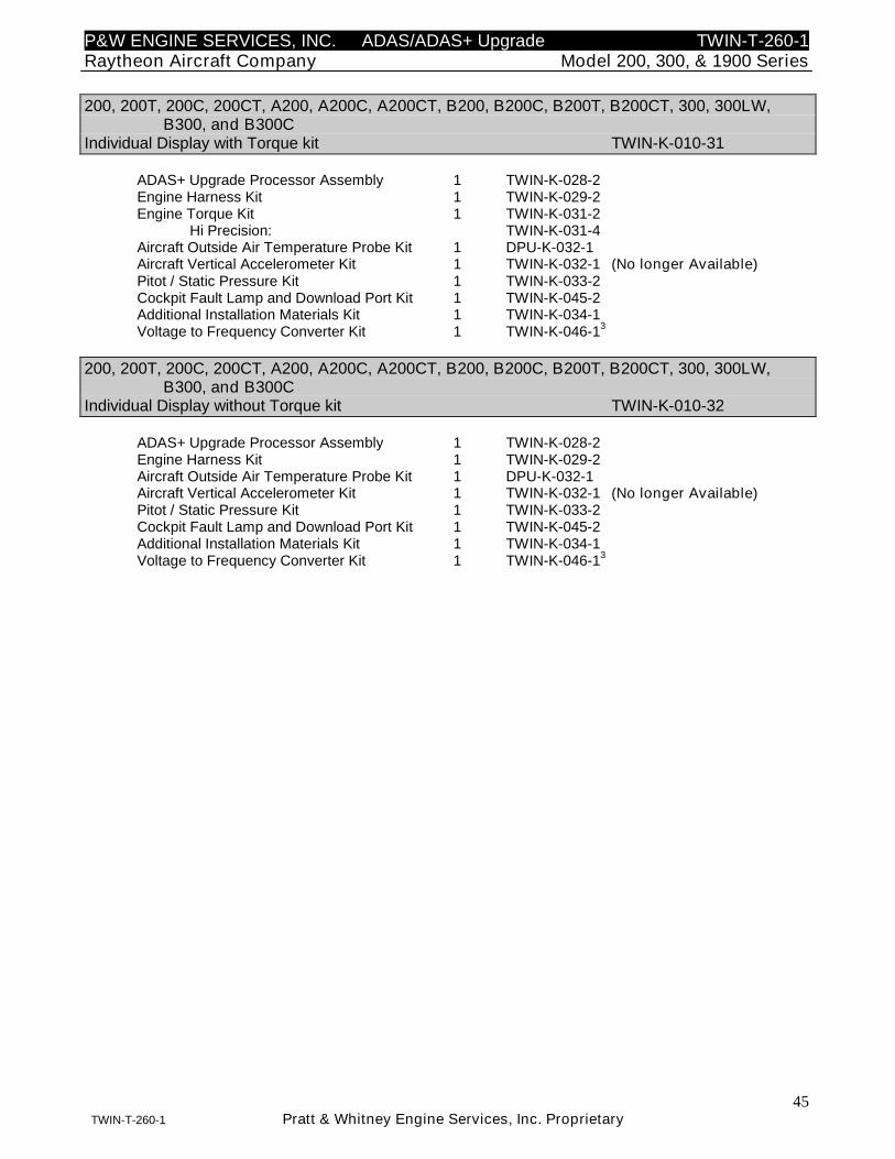
P&W ENGINE SERVICES, INC. ADAS/ADAS+ Upgrade TWIN-T-260-1Raytheon Aircraft Company Model 200, 300, & 1900 Series
45TWIN-T-260-1 Pratt & Whitney Engine Services, Inc. Proprietary
200, 200T, 200C, 200CT, A200, A200C, A200CT, B200, B200C, B200T, B200CT, 300, 300LW,B300, and B300C
Individual Display with Torque kit TWIN-K-010-31
ADAS+ Upgrade Processor Assembly 1 TWIN-K-028-2Engine Harness Kit 1 TWIN-K-029-2Engine Torque Kit 1 TWIN-K-031-2
Hi Precision: TWIN-K-031-4Aircraft Outside Air Temperature Probe Kit 1 DPU-K-032-1Aircraft Vertical Accelerometer Kit 1 TWIN-K-032-1 (No longer Available)Pitot / Static Pressure Kit 1 TWIN-K-033-2Cockpit Fault Lamp and Download Port Kit 1 TWIN-K-045-2Additional Installation Materials Kit 1 TWIN-K-034-1Voltage to Frequency Converter Kit 1 TWIN-K-046-1
3
200, 200T, 200C, 200CT, A200, A200C, A200CT, B200, B200C, B200T, B200CT, 300, 300LW,B300, and B300C
Individual Display without Torque kit TWIN-K-010-32
ADAS+ Upgrade Processor Assembly 1 TWIN-K-028-2Engine Harness Kit 1 TWIN-K-029-2Aircraft Outside Air Temperature Probe Kit 1 DPU-K-032-1Aircraft Vertical Accelerometer Kit 1 TWIN-K-032-1 (No longer Available)Pitot / Static Pressure Kit 1 TWIN-K-033-2Cockpit Fault Lamp and Download Port Kit 1 TWIN-K-045-2Additional Installation Materials Kit 1 TWIN-K-034-1Voltage to Frequency Converter Kit 1 TWIN-K-046-1
3
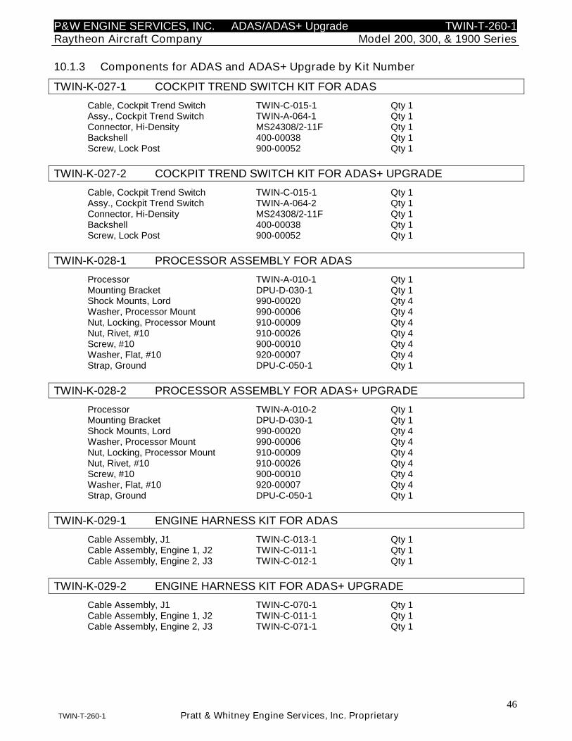
P&W ENGINE SERVICES, INC. ADAS/ADAS+ Upgrade TWIN-T-260-1Raytheon Aircraft Company Model 200, 300, & 1900 Series
46TWIN-T-260-1 Pratt & Whitney Engine Services, Inc. Proprietary
10.1.3 Components for ADAS and ADAS+ Upgrade by Kit Number
TWIN-K-027-1 COCKPIT TREND SWITCH KIT FOR ADAS
Cable, Cockpit Trend Switch TWIN-C-015-1 Qty 1Assy., Cockpit Trend Switch TWIN-A-064-1 Qty 1Connector, Hi-Density MS24308/2-11F Qty 1Backshell 400-00038 Qty 1Screw, Lock Post 900-00052 Qty 1
TWIN-K-027-2 COCKPIT TREND SWITCH KIT FOR ADAS+ UPGRADE
Cable, Cockpit Trend Switch TWIN-C-015-1 Qty 1Assy., Cockpit Trend Switch TWIN-A-064-2 Qty 1Connector, Hi-Density MS24308/2-11F Qty 1Backshell 400-00038 Qty 1Screw, Lock Post 900-00052 Qty 1
TWIN-K-028-1 PROCESSOR ASSEMBLY FOR ADAS
Processor TWIN-A-010-1 Qty 1Mounting Bracket DPU-D-030-1 Qty 1Shock Mounts, Lord 990-00020 Qty 4Washer, Processor Mount 990-00006 Qty 4Nut, Locking, Processor Mount 910-00009 Qty 4Nut, Rivet, #10 910-00026 Qty 4Screw, #10 900-00010 Qty 4Washer, Flat, #10 920-00007 Qty 4Strap, Ground DPU-C-050-1 Qty 1
TWIN-K-028-2 PROCESSOR ASSEMBLY FOR ADAS+ UPGRADE
Processor TWIN-A-010-2 Qty 1Mounting Bracket DPU-D-030-1 Qty 1Shock Mounts, Lord 990-00020 Qty 4Washer, Processor Mount 990-00006 Qty 4Nut, Locking, Processor Mount 910-00009 Qty 4Nut, Rivet, #10 910-00026 Qty 4Screw, #10 900-00010 Qty 4Washer, Flat, #10 920-00007 Qty 4Strap, Ground DPU-C-050-1 Qty 1
TWIN-K-029-1 ENGINE HARNESS KIT FOR ADAS
Cable Assembly, J1 TWIN-C-013-1 Qty 1Cable Assembly, Engine 1, J2 TWIN-C-011-1 Qty 1Cable Assembly, Engine 2, J3 TWIN-C-012-1 Qty 1
TWIN-K-029-2 ENGINE HARNESS KIT FOR ADAS+ UPGRADE
Cable Assembly, J1 TWIN-C-070-1 Qty 1Cable Assembly, Engine 1, J2 TWIN-C-011-1 Qty 1Cable Assembly, Engine 2, J3 TWIN-C-071-1 Qty 1
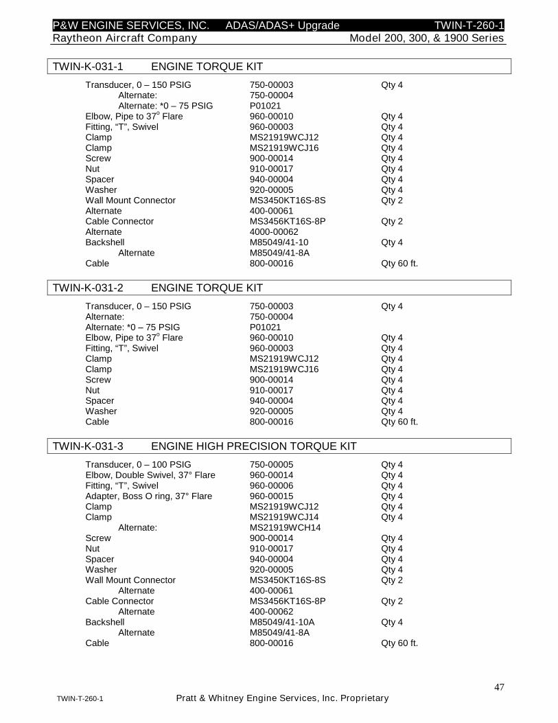
P&W ENGINE SERVICES, INC. ADAS/ADAS+ Upgrade TWIN-T-260-1Raytheon Aircraft Company Model 200, 300, & 1900 Series
47TWIN-T-260-1 Pratt & Whitney Engine Services, Inc. Proprietary
TWIN-K-031-1 ENGINE TORQUE KIT
Transducer, 0 – 150 PSIG 750-00003 Qty 4Alternate: 750-00004Alternate: *0 – 75 PSIG P01021
Elbow, Pipe to 37o
Flare 960-00010 Qty 4Fitting, “T”, Swivel 960-00003 Qty 4Clamp MS21919WCJ12 Qty 4Clamp MS21919WCJ16 Qty 4Screw 900-00014 Qty 4Nut 910-00017 Qty 4Spacer 940-00004 Qty 4Washer 920-00005 Qty 4Wall Mount Connector MS3450KT16S-8S Qty 2Alternate 400-00061Cable Connector MS3456KT16S-8P Qty 2Alternate 4000-00062Backshell M85049/41-10 Qty 4
Alternate M85049/41-8ACable 800-00016 Qty 60 ft.
TWIN-K-031-2 ENGINE TORQUE KIT
Transducer, 0 – 150 PSIG 750-00003 Qty 4Alternate: 750-00004Alternate: *0 – 75 PSIG P01021Elbow, Pipe to 37
oFlare 960-00010 Qty 4
Fitting, “T”, Swivel 960-00003 Qty 4Clamp MS21919WCJ12 Qty 4Clamp MS21919WCJ16 Qty 4Screw 900-00014 Qty 4Nut 910-00017 Qty 4Spacer 940-00004 Qty 4Washer 920-00005 Qty 4Cable 800-00016 Qty 60 ft.
TWIN-K-031-3 ENGINE HIGH PRECISION TORQUE KIT
Transducer, 0 – 100 PSIG 750-00005 Qty 4Elbow, Double Swivel, 37° Flare 960-00014 Qty 4Fitting, “T”, Swivel 960-00006 Qty 4Adapter, Boss O ring, 37° Flare 960-00015 Qty 4Clamp MS21919WCJ12 Qty 4Clamp MS21919WCJ14 Qty 4
Alternate: MS21919WCH14Screw 900-00014 Qty 4Nut 910-00017 Qty 4Spacer 940-00004 Qty 4Washer 920-00005 Qty 4Wall Mount Connector MS3450KT16S-8S Qty 2
Alternate 400-00061Cable Connector MS3456KT16S-8P Qty 2
Alternate 400-00062Backshell M85049/41-10A Qty 4
Alternate M85049/41-8ACable 800-00016 Qty 60 ft.
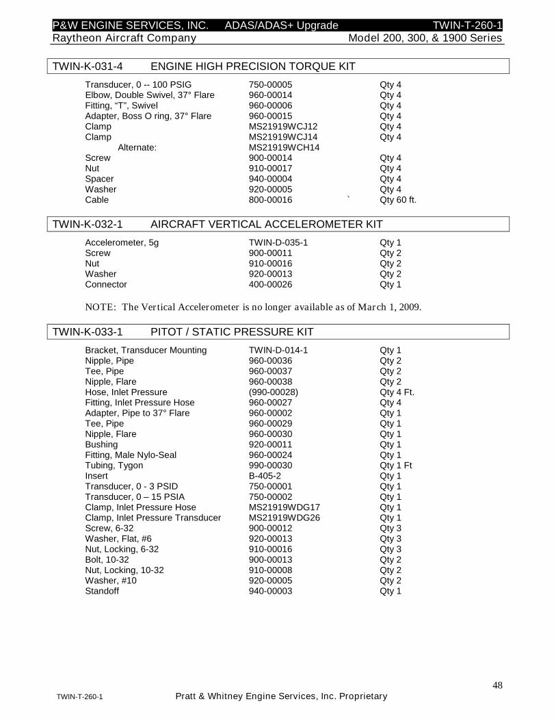
P&W ENGINE SERVICES, INC. ADAS/ADAS+ Upgrade TWIN-T-260-1Raytheon Aircraft Company Model 200, 300, & 1900 Series
48TWIN-T-260-1 Pratt & Whitney Engine Services, Inc. Proprietary
TWIN-K-031-4 ENGINE HIGH PRECISION TORQUE KIT
Transducer, 0 -- 100 PSIG 750-00005 Qty 4Elbow, Double Swivel, 37° Flare 960-00014 Qty 4Fitting, “T”, Swivel 960-00006 Qty 4Adapter, Boss O ring, 37° Flare 960-00015 Qty 4Clamp MS21919WCJ12 Qty 4Clamp MS21919WCJ14 Qty 4
Alternate: MS21919WCH14Screw 900-00014 Qty 4Nut 910-00017 Qty 4Spacer 940-00004 Qty 4Washer 920-00005 Qty 4Cable 800-00016 ` Qty 60 ft.
TWIN-K-032-1 AIRCRAFT VERTICAL ACCELEROMETER KIT
Accelerometer, 5g TWIN-D-035-1 Qty 1Screw 900-00011 Qty 2Nut 910-00016 Qty 2Washer 920-00013 Qty 2Connector 400-00026 Qty 1
NOTE: The Vertical Accelerometer is no longer available as of March 1, 2009.
TWIN-K-033-1 PITOT / STATIC PRESSURE KIT
Bracket, Transducer Mounting TWIN-D-014-1 Qty 1Nipple, Pipe 960-00036 Qty 2Tee, Pipe 960-00037 Qty 2Nipple, Flare 960-00038 Qty 2Hose, Inlet Pressure (990-00028) Qty 4 Ft.Fitting, Inlet Pressure Hose 960-00027 Qty 4Adapter, Pipe to 37° Flare 960-00002 Qty 1Tee, Pipe 960-00029 Qty 1Nipple, Flare 960-00030 Qty 1Bushing 920-00011 Qty 1Fitting, Male Nylo-Seal 960-00024 Qty 1Tubing, Tygon 990-00030 Qty 1 FtInsert B-405-2 Qty 1Transducer, 0 - 3 PSID 750-00001 Qty 1Transducer, 0 – 15 PSIA 750-00002 Qty 1Clamp, Inlet Pressure Hose MS21919WDG17 Qty 1Clamp, Inlet Pressure Transducer MS21919WDG26 Qty 1Screw, 6-32 900-00012 Qty 3Washer, Flat, #6 920-00013 Qty 3Nut, Locking, 6-32 910-00016 Qty 3Bolt, 10-32 900-00013 Qty 2Nut, Locking, 10-32 910-00008 Qty 2Washer, #10 920-00005 Qty 2Standoff 940-00003 Qty 1
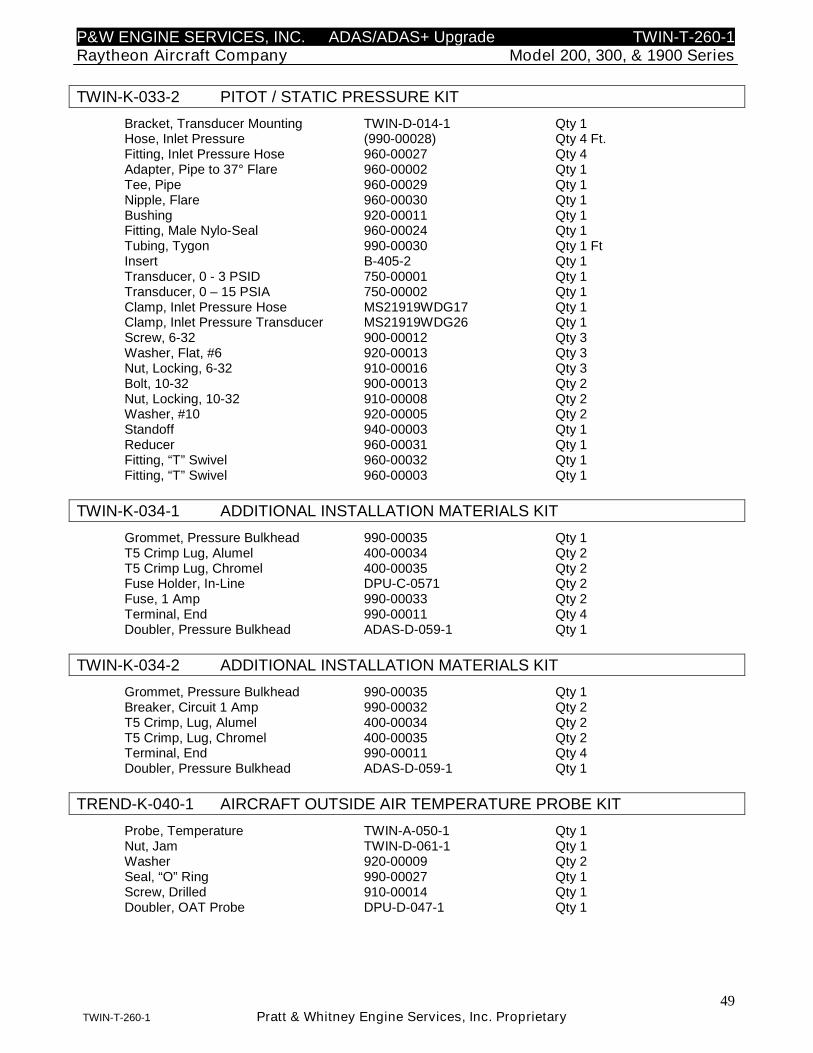
P&W ENGINE SERVICES, INC. ADAS/ADAS+ Upgrade TWIN-T-260-1Raytheon Aircraft Company Model 200, 300, & 1900 Series
49TWIN-T-260-1 Pratt & Whitney Engine Services, Inc. Proprietary
TWIN-K-033-2 PITOT / STATIC PRESSURE KIT
Bracket, Transducer Mounting TWIN-D-014-1 Qty 1Hose, Inlet Pressure (990-00028) Qty 4 Ft.Fitting, Inlet Pressure Hose 960-00027 Qty 4Adapter, Pipe to 37° Flare 960-00002 Qty 1Tee, Pipe 960-00029 Qty 1Nipple, Flare 960-00030 Qty 1Bushing 920-00011 Qty 1Fitting, Male Nylo-Seal 960-00024 Qty 1Tubing, Tygon 990-00030 Qty 1 FtInsert B-405-2 Qty 1Transducer, 0 - 3 PSID 750-00001 Qty 1Transducer, 0 – 15 PSIA 750-00002 Qty 1Clamp, Inlet Pressure Hose MS21919WDG17 Qty 1Clamp, Inlet Pressure Transducer MS21919WDG26 Qty 1Screw, 6-32 900-00012 Qty 3Washer, Flat, #6 920-00013 Qty 3Nut, Locking, 6-32 910-00016 Qty 3Bolt, 10-32 900-00013 Qty 2Nut, Locking, 10-32 910-00008 Qty 2Washer, #10 920-00005 Qty 2Standoff 940-00003 Qty 1Reducer 960-00031 Qty 1Fitting, “T” Swivel 960-00032 Qty 1Fitting, “T” Swivel 960-00003 Qty 1
TWIN-K-034-1 ADDITIONAL INSTALLATION MATERIALS KIT
Grommet, Pressure Bulkhead 990-00035 Qty 1T5 Crimp Lug, Alumel 400-00034 Qty 2T5 Crimp Lug, Chromel 400-00035 Qty 2Fuse Holder, In-Line DPU-C-0571 Qty 2Fuse, 1 Amp 990-00033 Qty 2Terminal, End 990-00011 Qty 4Doubler, Pressure Bulkhead ADAS-D-059-1 Qty 1
TWIN-K-034-2 ADDITIONAL INSTALLATION MATERIALS KIT
Grommet, Pressure Bulkhead 990-00035 Qty 1Breaker, Circuit 1 Amp 990-00032 Qty 2T5 Crimp, Lug, Alumel 400-00034 Qty 2T5 Crimp, Lug, Chromel 400-00035 Qty 2Terminal, End 990-00011 Qty 4Doubler, Pressure Bulkhead ADAS-D-059-1 Qty 1
TREND-K-040-1 AIRCRAFT OUTSIDE AIR TEMPERATURE PROBE KIT
Probe, Temperature TWIN-A-050-1 Qty 1Nut, Jam TWIN-D-061-1 Qty 1Washer 920-00009 Qty 2Seal, “O” Ring 990-00027 Qty 1Screw, Drilled 910-00014 Qty 1Doubler, OAT Probe DPU-D-047-1 Qty 1
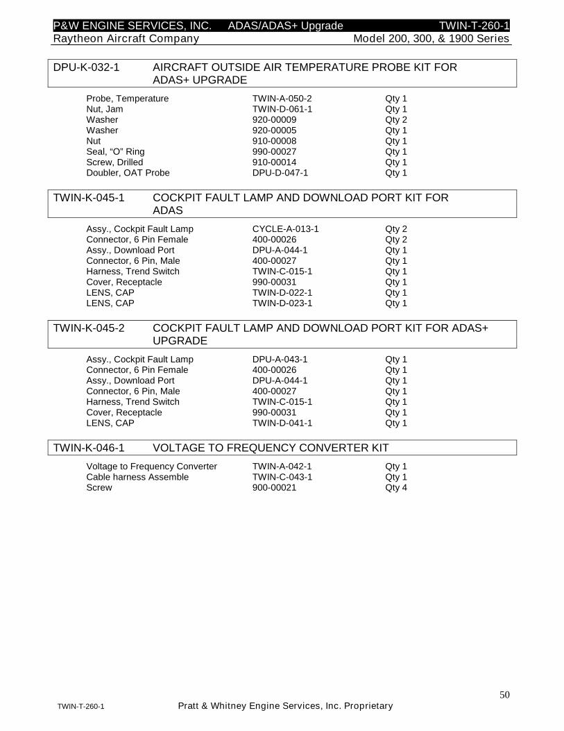
P&W ENGINE SERVICES, INC. ADAS/ADAS+ Upgrade TWIN-T-260-1Raytheon Aircraft Company Model 200, 300, & 1900 Series
50TWIN-T-260-1 Pratt & Whitney Engine Services, Inc. Proprietary
DPU-K-032-1 AIRCRAFT OUTSIDE AIR TEMPERATURE PROBE KIT FORADAS+ UPGRADE
Probe, Temperature TWIN-A-050-2 Qty 1Nut, Jam TWIN-D-061-1 Qty 1Washer 920-00009 Qty 2Washer 920-00005 Qty 1Nut 910-00008 Qty 1Seal, “O” Ring 990-00027 Qty 1Screw, Drilled 910-00014 Qty 1Doubler, OAT Probe DPU-D-047-1 Qty 1
TWIN-K-045-1 COCKPIT FAULT LAMP AND DOWNLOAD PORT KIT FORADAS
Assy., Cockpit Fault Lamp CYCLE-A-013-1 Qty 2Connector, 6 Pin Female 400-00026 Qty 2Assy., Download Port DPU-A-044-1 Qty 1Connector, 6 Pin, Male 400-00027 Qty 1Harness, Trend Switch TWIN-C-015-1 Qty 1Cover, Receptacle 990-00031 Qty 1LENS, CAP TWIN-D-022-1 Qty 1LENS, CAP TWIN-D-023-1 Qty 1
TWIN-K-045-2 COCKPIT FAULT LAMP AND DOWNLOAD PORT KIT FOR ADAS+UPGRADE
Assy., Cockpit Fault Lamp DPU-A-043-1 Qty 1Connector, 6 Pin Female 400-00026 Qty 1Assy., Download Port DPU-A-044-1 Qty 1Connector, 6 Pin, Male 400-00027 Qty 1Harness, Trend Switch TWIN-C-015-1 Qty 1Cover, Receptacle 990-00031 Qty 1LENS, CAP TWIN-D-041-1 Qty 1
TWIN-K-046-1 VOLTAGE TO FREQUENCY CONVERTER KIT
Voltage to Frequency Converter TWIN-A-042-1 Qty 1Cable harness Assemble TWIN-C-043-1 Qty 1Screw 900-00021 Qty 4
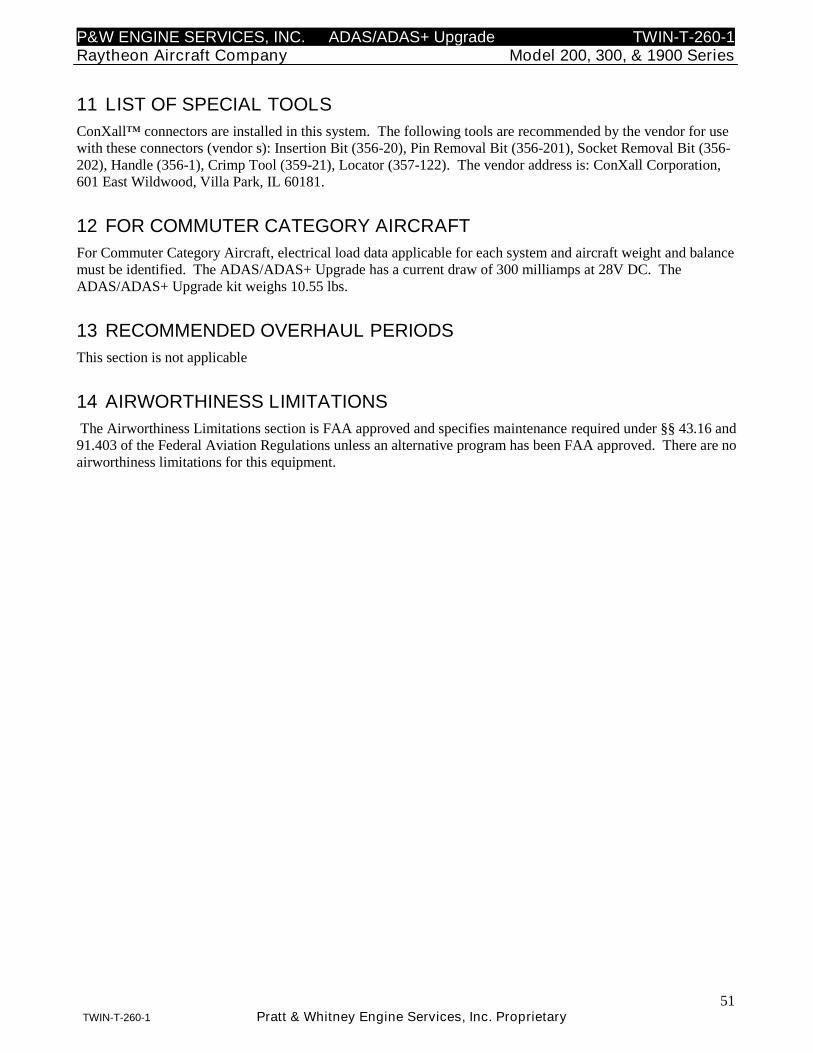
P&W ENGINE SERVICES, INC. ADAS/ADAS+ Upgrade TWIN-T-260-1Raytheon Aircraft Company Model 200, 300, & 1900 Series
51TWIN-T-260-1 Pratt & Whitney Engine Services, Inc. Proprietary
11 LIST OF SPECIAL TOOLS
ConXall™ connectors are installed in this system. The following tools are recommended by the vendor for usewith these connectors (vendor s): Insertion Bit (356-20), Pin Removal Bit (356-201), Socket Removal Bit (356-202), Handle (356-1), Crimp Tool (359-21), Locator (357-122). The vendor address is: ConXall Corporation,601 East Wildwood, Villa Park, IL 60181.
12 FOR COMMUTER CATEGORY AIRCRAFT
For Commuter Category Aircraft, electrical load data applicable for each system and aircraft weight and balancemust be identified. The ADAS/ADAS+ Upgrade has a current draw of 300 milliamps at 28V DC. TheADAS/ADAS+ Upgrade kit weighs 10.55 lbs.
13 RECOMMENDED OVERHAUL PERIODS
This section is not applicable
14 AIRWORTHINESS LIMITATIONS
The Airworthiness Limitations section is FAA approved and specifies maintenance required under §§ 43.16 and91.403 of the Federal Aviation Regulations unless an alternative program has been FAA approved. There are noairworthiness limitations for this equipment.
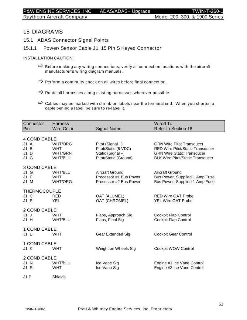
P&W ENGINE SERVICES, INC. ADAS/ADAS+ Upgrade TWIN-T-260-1Raytheon Aircraft Company Model 200, 300, & 1900 Series
52TWIN-T-260-1 Pratt & Whitney Engine Services, Inc. Proprietary
15 DIAGRAMS
15.1 ADAS Connector Signal Points
15.1.1 Power/ Sensor Cable J1, 15 Pin S Keyed Connector
INSTALLATION CAUTION:
Before making any wiring connections, verify all connection locations with the aircraftmanufacturer’s wiring diagram manuals.
Perform a continuity check on all wires before final connection.
Route all harnesses along existing harnesses wherever possible.
Cables may be marked with shrink-on labels near the terminal end. When you shorten acable behind a label, be sure to re-label it.
Connector Harness Wired ToPin Wire Color Signal Name Refer to Section 16
4 COND CABLEJ1 A WHT/ORG Pitot (Signal +) GRN Wire Pitot TransducerJ1 B WHT Pitot/Static (5 VDC) RED Wire Pitot/Static TransducerJ1 D WHT/GRN Static (Signal –) GRN Wire Static TransducerJ1 G WHT/BLU Pitot/Static (Ground) BLK Wire Pitot/Static Transducer
3 COND CABLEJ1 G WHT/BLU Aircraft Ground Aircraft GroundJ1 F WHT Processor #1 Bus Power Bus Power, Supplied 1 Amp FuseJ1 M WHT/ORG Processor #2 Bus Power Bus Power, Supplied 1 Amp Fuse
THERMOCOUPLEJ1 C RED OAT (ALUMEL) RED Wire OAT ProbeJ1 E YEL OAT (CHROMEL) YEL Wire OAT Probe
2 COND CABLEJ1 J WHT Flaps, Approach Sig Cockpit Flap ControlJ1 H WHT/BLU Flaps, Final Sig Cockpit Flap Control
1 COND CABLEJ1 L WHT Gear Extended Sig Cockpit Gear Control
1 COND CABLEJ1 K WHT Weight on Wheels Sig Cockpit WOW Control
2 COND CABLEJ1 N WHT/BLU Ice Vane Sig Engine #1 Ice Vane ControlJ1 R WHT Ice Vane Sig Engine #2 Ice Vane Control
J1 P Shields
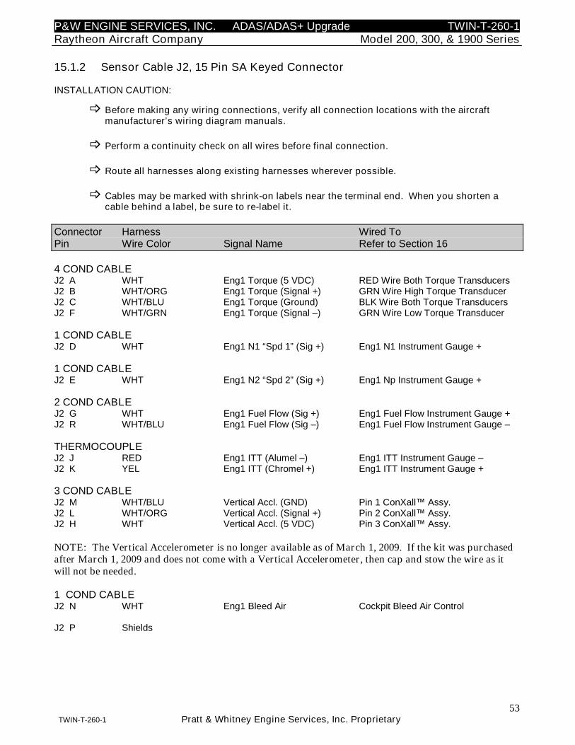
P&W ENGINE SERVICES, INC. ADAS/ADAS+ Upgrade TWIN-T-260-1Raytheon Aircraft Company Model 200, 300, & 1900 Series
53TWIN-T-260-1 Pratt & Whitney Engine Services, Inc. Proprietary
15.1.2 Sensor Cable J2, 15 Pin SA Keyed Connector
INSTALLATION CAUTION:
Before making any wiring connections, verify all connection locations with the aircraftmanufacturer’s wiring diagram manuals.
Perform a continuity check on all wires before final connection.
Route all harnesses along existing harnesses wherever possible.
Cables may be marked with shrink-on labels near the terminal end. When you shorten acable behind a label, be sure to re-label it.
Connector Harness Wired ToPin Wire Color Signal Name Refer to Section 16
4 COND CABLEJ2 A WHT Eng1 Torque (5 VDC) RED Wire Both Torque TransducersJ2 B WHT/ORG Eng1 Torque (Signal +) GRN Wire High Torque TransducerJ2 C WHT/BLU Eng1 Torque (Ground) BLK Wire Both Torque TransducersJ2 F WHT/GRN Eng1 Torque (Signal –) GRN Wire Low Torque Transducer
1 COND CABLEJ2 D WHT Eng1 N1 “Spd 1” (Sig +) Eng1 N1 Instrument Gauge +
1 COND CABLEJ2 E WHT Eng1 N2 “Spd 2” (Sig +) Eng1 Np Instrument Gauge +
2 COND CABLEJ2 G WHT Eng1 Fuel Flow (Sig +) Eng1 Fuel Flow Instrument Gauge +J2 R WHT/BLU Eng1 Fuel Flow (Sig –) Eng1 Fuel Flow Instrument Gauge –
THERMOCOUPLEJ2 J RED Eng1 ITT (Alumel –) Eng1 ITT Instrument Gauge –J2 K YEL Eng1 ITT (Chromel +) Eng1 ITT Instrument Gauge +
3 COND CABLEJ2 M WHT/BLU Vertical Accl. (GND) Pin 1 ConXall™ Assy.J2 L WHT/ORG Vertical Accl. (Signal +) Pin 2 ConXall™ Assy.J2 H WHT Vertical Accl. (5 VDC) Pin 3 ConXall™ Assy.
NOTE: The Vertical Accelerometer is no longer available as of March 1, 2009. If the kit was purchasedafter March 1, 2009 and does not come with a Vertical Accelerometer, then cap and stow the wire as itwill not be needed.
1 COND CABLEJ2 N WHT Eng1 Bleed Air Cockpit Bleed Air Control
J2 P Shields

P&W ENGINE SERVICES, INC. ADAS/ADAS+ Upgrade TWIN-T-260-1Raytheon Aircraft Company Model 200, 300, & 1900 Series
54TWIN-T-260-1 Pratt & Whitney Engine Services, Inc. Proprietary
15.1.3 Cockpit Trend / Sensor Cable, J3, 37 Pin S Keyed Connector
INSTALLATION CAUTION:
Before making any wiring connections, verify all connection locations with the aircraftmanufacturer’s wiring diagram manuals.
Perform a continuity check on all wires before final connection.
Route all harnesses along existing harnesses wherever possible.
Cables may be marked with shrink-on labels near the terminal end. When you shorten acable behind a label, be sure to re-label it.
Connector Harness Wired ToPin Wire Color Signal Name Refer to Section 16
4 COND CABLEJ3 A WHT Eng2 Torque (5 VDC) RED Wire Both Torque TransducersJ3 B WHT/ORG Eng2 Torque (Signal +) GRN Wire High Torque TransducerJ3 C WHT/BLU Eng2 Torque (Ground) BLK Wire Both Torque TransducersJ3 F WHT/GRN Eng2 Torque (Signal –) GRN Wire Low Torque Transducer
1 COND CABLEJ3 D WHT Eng2 N1 “Spd 1” (Sig +) Eng2 N1 Instrument Gauge +
1 COND CABLEJ3 E WHT Eng2 N2 “Spd 2” (Sig +) Eng2 Np Instrument Gauge +
2 COND CABLEJ3 G WHT Eng2 Fuel Flow (Sig +) Eng2 Fuel Flow Instrument Gauge +J3 R WHT/BLU Eng2 Fuel Flow (Sig –) Eng2 Fuel Flow Instrument Gauge –
THERMOCOUPLEJ3 J RED Eng2 ITT (Alumel –) Eng2 ITT Instrument Gauge –J3 K YEL Eng2 ITT (Chromel +) Eng2 ITT Instrument Gauge +
1 COND CABLEJ3 N WHT Eng2 Bleed Air Cockpit Bleed Air Control
J3 P Shields
J3 H (Unused)J3 L (Unused)J3 M (Unused)
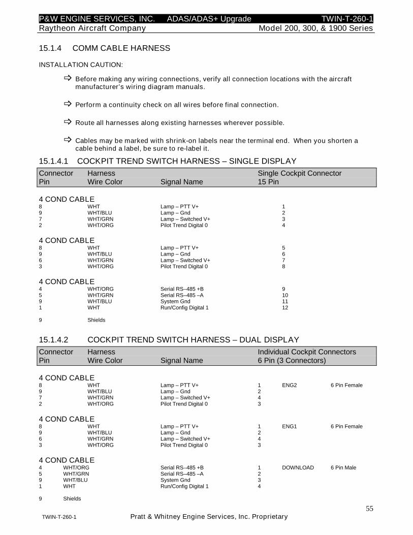
P&W ENGINE SERVICES, INC. ADAS/ADAS+ Upgrade TWIN-T-260-1Raytheon Aircraft Company Model 200, 300, & 1900 Series
55TWIN-T-260-1 Pratt & Whitney Engine Services, Inc. Proprietary
15.1.4 COMM CABLE HARNESS
INSTALLATION CAUTION:
Before making any wiring connections, verify all connection locations with the aircraftmanufacturer’s wiring diagram manuals.
Perform a continuity check on all wires before final connection.
Route all harnesses along existing harnesses wherever possible.
Cables may be marked with shrink-on labels near the terminal end. When you shorten acable behind a label, be sure to re-label it.
15.1.4.1 COCKPIT TREND SWITCH HARNESS – SINGLE DISPLAY
Connector Harness Single Cockpit ConnectorPin Wire Color Signal Name 15 Pin
4 COND CABLE8 WHT Lamp – PTT V+ 19 WHT/BLU Lamp – Gnd 27 WHT/GRN Lamp – Switched V+ 32 WHT/ORG Pilot Trend Digital 0 4
4 COND CABLE8 WHT Lamp – PTT V+ 59 WHT/BLU Lamp – Gnd 66 WHT/GRN Lamp – Switched V+ 73 WHT/ORG Pilot Trend Digital 0 8
4 COND CABLE4 WHT/ORG Serial RS–485 +B 95 WHT/GRN Serial RS–485 –A 109 WHT/BLU System Gnd 111 WHT Run/Config Digital 1 12
9 Shields
15.1.4.2 COCKPIT TREND SWITCH HARNESS – DUAL DISPLAY
Connector Harness Individual Cockpit ConnectorsPin Wire Color Signal Name 6 Pin (3 Connectors)
4 COND CABLE8 WHT Lamp – PTT V+ 1 ENG2 6 Pin Female9 WHT/BLU Lamp – Gnd 27 WHT/GRN Lamp – Switched V+ 42 WHT/ORG Pilot Trend Digital 0 3
4 COND CABLE8 WHT Lamp – PTT V+ 1 ENG1 6 Pin Female9 WHT/BLU Lamp – Gnd 26 WHT/GRN Lamp – Switched V+ 43 WHT/ORG Pilot Trend Digital 0 3
4 COND CABLE4 WHT/ORG Serial RS–485 +B 1 DOWNLOAD 6 Pin Male5 WHT/GRN Serial RS–485 –A 29 WHT/BLU System Gnd 31 WHT Run/Config Digital 1 4
9 Shields
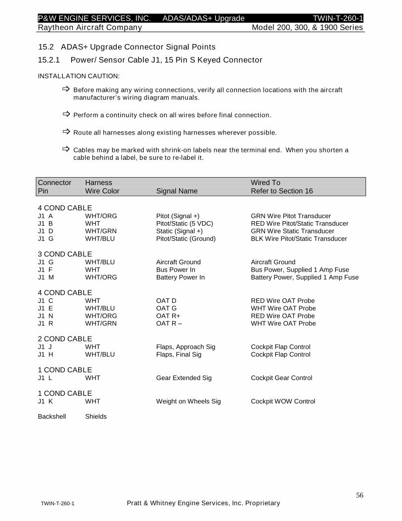
P&W ENGINE SERVICES, INC. ADAS/ADAS+ Upgrade TWIN-T-260-1Raytheon Aircraft Company Model 200, 300, & 1900 Series
56TWIN-T-260-1 Pratt & Whitney Engine Services, Inc. Proprietary
15.2 ADAS+ Upgrade Connector Signal Points
15.2.1 Power/ Sensor Cable J1, 15 Pin S Keyed Connector
INSTALLATION CAUTION:
Before making any wiring connections, verify all connection locations with the aircraftmanufacturer’s wiring diagram manuals.
Perform a continuity check on all wires before final connection.
Route all harnesses along existing harnesses wherever possible.
Cables may be marked with shrink-on labels near the terminal end. When you shorten acable behind a label, be sure to re-label it.
Connector Harness Wired ToPin Wire Color Signal Name Refer to Section 16
4 COND CABLEJ1 A WHT/ORG Pitot (Signal +) GRN Wire Pitot TransducerJ1 B WHT Pitot/Static (5 VDC) RED Wire Pitot/Static TransducerJ1 D WHT/GRN Static (Signal +) GRN Wire Static TransducerJ1 G WHT/BLU Pitot/Static (Ground) BLK Wire Pitot/Static Transducer
3 COND CABLEJ1 G WHT/BLU Aircraft Ground Aircraft GroundJ1 F WHT Bus Power In Bus Power, Supplied 1 Amp FuseJ1 M WHT/ORG Battery Power In Battery Power, Supplied 1 Amp Fuse
4 COND CABLEJ1 C WHT OAT D RED Wire OAT ProbeJ1 E WHT/BLU OAT G WHT Wire OAT ProbeJ1 N WHT/ORG OAT R+ RED Wire OAT ProbeJ1 R WHT/GRN OAT R – WHT Wire OAT Probe
2 COND CABLEJ1 J WHT Flaps, Approach Sig Cockpit Flap ControlJ1 H WHT/BLU Flaps, Final Sig Cockpit Flap Control
1 COND CABLEJ1 L WHT Gear Extended Sig Cockpit Gear Control
1 COND CABLEJ1 K WHT Weight on Wheels Sig Cockpit WOW Control
Backshell Shields
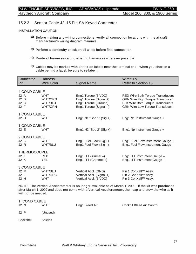
P&W ENGINE SERVICES, INC. ADAS/ADAS+ Upgrade TWIN-T-260-1Raytheon Aircraft Company Model 200, 300, & 1900 Series
57TWIN-T-260-1 Pratt & Whitney Engine Services, Inc. Proprietary
15.2.2 Sensor Cable J2, 15 Pin SA Keyed Connector
INSTALLATION CAUTION:
Before making any wiring connections, verify all connection locations with the aircraftmanufacturer’s wiring diagram manuals.
Perform a continuity check on all wires before final connection.
Route all harnesses along existing harnesses wherever possible.
Cables may be marked with shrink-on labels near the terminal end. When you shorten acable behind a label, be sure to re-label it.
Connector Harness Wired ToPin Wire Color Signal Name Refer to Section 16
4 COND CABLEJ2 A WHT Eng1 Torque (5 VDC) RED Wire Both Torque TransducersJ2 B WHT/ORG Eng1 Torque (Signal +) GRN Wire High Torque TransducerJ2 C WHT/BLU Eng1 Torque (Ground) BLK Wire Both Torque TransducersJ2 F WHT/GRN Eng1 Torque (Signal –) GRN Wire Low Torque Transducer
1 COND CABLEJ2 D WHT Eng1 N1 “Spd 1” (Sig +) Eng1 N1 Instrument Gauge +
1 COND CABLEJ2 E WHT Eng1 N2 “Spd 2” (Sig +) Eng1 Np Instrument Gauge +
2 COND CABLEJ2 G WHT Eng1 Fuel Flow (Sig +) Eng1 Fuel Flow Instrument Gauge +J2 R WHT/BLU Eng1 Fuel Flow (Sig –) Eng1 Fuel Flow Instrument Gauge –
THERMOCOUPLEJ2 J RED Eng1 ITT (Alumel –) Eng1 ITT Instrument Gauge –J2 K YEL Eng1 ITT (Chromel +) Eng1 ITT Instrument Gauge +
3 COND CABLEJ2 M WHT/BLU Vertical Accl. (GND) Pin 1 ConXall™ Assy.J2 L WHT/ORG Vertical Accl. (Signal +) Pin 2 ConXall™ Assy.J2 H WHT Vertical Accl. (5 VDC) Pin 3 ConXall™ Assy.
NOTE: The Vertical Accelerometer is no longer available as of March 1, 2009. If the kit was purchasedafter March 1, 2009 and does not come with a Vertical Accelerometer, then cap and stow the wire as itwill not be needed.
1 COND CABLEJ2 N WHT Eng1 Bleed Air Cockpit Bleed Air Control
J2 P (Unused)
Backshell Shields
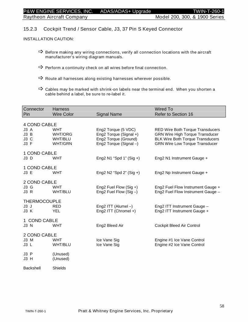
P&W ENGINE SERVICES, INC. ADAS/ADAS+ Upgrade TWIN-T-260-1Raytheon Aircraft Company Model 200, 300, & 1900 Series
58TWIN-T-260-1 Pratt & Whitney Engine Services, Inc. Proprietary
15.2.3 Cockpit Trend / Sensor Cable, J3, 37 Pin S Keyed Connector
INSTALLATION CAUTION:
Before making any wiring connections, verify all connection locations with the aircraftmanufacturer’s wiring diagram manuals.
Perform a continuity check on all wires before final connection.
Route all harnesses along existing harnesses wherever possible.
Cables may be marked with shrink-on labels near the terminal end. When you shorten acable behind a label, be sure to re-label it.
Connector Harness Wired ToPin Wire Color Signal Name Refer to Section 16
4 COND CABLEJ3 A WHT Eng2 Torque (5 VDC) RED Wire Both Torque TransducersJ3 B WHT/ORG Eng2 Torque (Signal +) GRN Wire High Torque TransducerJ3 C WHT/BLU Eng2 Torque (Ground) BLK Wire Both Torque TransducersJ3 F WHT/GRN Eng2 Torque (Signal –) GRN Wire Low Torque Transducer
1 COND CABLEJ3 D WHT Eng2 N1 “Spd 1” (Sig +) Eng2 N1 Instrument Gauge +
1 COND CABLEJ3 E WHT Eng2 N2 “Spd 2” (Sig +) Eng2 Np Instrument Gauge +
2 COND CABLEJ3 G WHT Eng2 Fuel Flow (Sig +) Eng2 Fuel Flow Instrument Gauge +J3 R WHT/BLU Eng2 Fuel Flow (Sig –) Eng2 Fuel Flow Instrument Gauge –
THERMOCOUPLEJ3 J RED Eng2 ITT (Alumel –) Eng2 ITT Instrument Gauge –J3 K YEL Eng2 ITT (Chromel +) Eng2 ITT Instrument Gauge +
1 COND CABLEJ3 N WHT Eng2 Bleed Air Cockpit Bleed Air Control
2 COND CABLEJ3 M WHT Ice Vane Sig Engine #1 Ice Vane ControlJ3 L WHT/BLU Ice Vane Sig Engine #2 Ice Vane Control
J3 P (Unused)J3 H (Unused)
Backshell Shields
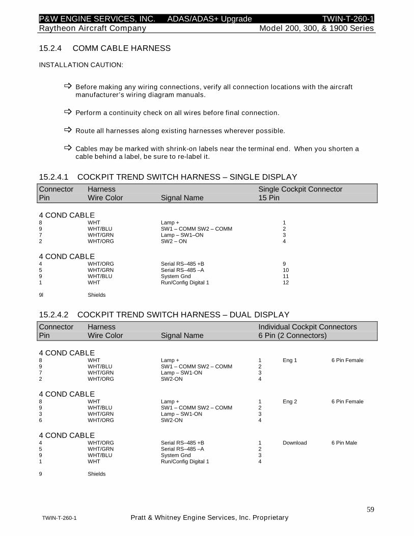
P&W ENGINE SERVICES, INC. ADAS/ADAS+ Upgrade TWIN-T-260-1Raytheon Aircraft Company Model 200, 300, & 1900 Series
59TWIN-T-260-1 Pratt & Whitney Engine Services, Inc. Proprietary
15.2.4 COMM CABLE HARNESS
INSTALLATION CAUTION:
Before making any wiring connections, verify all connection locations with the aircraftmanufacturer’s wiring diagram manuals.
Perform a continuity check on all wires before final connection.
Route all harnesses along existing harnesses wherever possible.
Cables may be marked with shrink-on labels near the terminal end. When you shorten acable behind a label, be sure to re-label it.
15.2.4.1 COCKPIT TREND SWITCH HARNESS – SINGLE DISPLAY
Connector Harness Single Cockpit ConnectorPin Wire Color Signal Name 15 Pin
4 COND CABLE8 WHT Lamp + 19 WHT/BLU SW1 – COMM SW2 – COMM 27 WHT/GRN Lamp – SW1–ON 32 WHT/ORG SW2 – ON 4
4 COND CABLE4 WHT/ORG Serial RS–485 +B 95 WHT/GRN Serial RS–485 –A 109 WHT/BLU System Gnd 111 WHT Run/Config Digital 1 12
9l Shields
15.2.4.2 COCKPIT TREND SWITCH HARNESS – DUAL DISPLAY
Connector Harness Individual Cockpit ConnectorsPin Wire Color Signal Name 6 Pin (2 Connectors)
4 COND CABLE8 WHT Lamp + 1 Eng 1 6 Pin Female9 WHT/BLU SW1 – COMM SW2 – COMM 27 WHT/GRN Lamp – SW1-ON 32 WHT/ORG SW2-ON 4
4 COND CABLE8 WHT Lamp + 1 Eng 2 6 Pin Female9 WHT/BLU SW1 – COMM SW2 – COMM 23 WHT/GRN Lamp – SW1-ON 36 WHT/ORG SW2-ON 4
4 COND CABLE4 WHT/ORG Serial RS–485 +B 1 Download 6 Pin Male5 WHT/GRN Serial RS–485 –A 29 WHT/BLU System Gnd 31 WHT Run/Config Digital 1 4
9 Shields
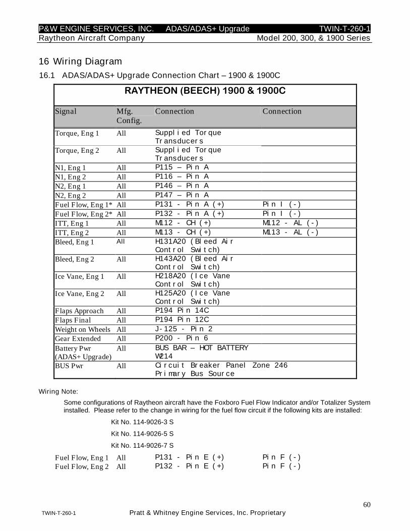
P&W ENGINE SERVICES, INC. ADAS/ADAS+ Upgrade TWIN-T-260-1Raytheon Aircraft Company Model 200, 300, & 1900 Series
60TWIN-T-260-1 Pratt & Whitney Engine Services, Inc. Proprietary
16 Wiring Diagram
16.1 ADAS/ADAS+ Upgrade Connection Chart – 1900 & 1900C
RAYTHEON (BEECH) 1900 & 1900C
Signal Mfg.Config.
Connection Connection
Torque, Eng 1 All Supplied TorqueTransducers
Torque, Eng 2 All Supplied TorqueTransducers
N1, Eng 1 All P115 – Pin A
N1, Eng 2 All P116 – Pin A
N2, Eng 1 All P146 – Pin A
N2, Eng 2 All P147 – Pin A
Fuel Flow, Eng 1* All P131 - Pin A (+) Pin I (-)
Fuel Flow, Eng 2* All P132 - Pin A (+) Pin I (-)
ITT, Eng 1 All M112 - CH (+) M112 - AL (-)
ITT, Eng 2 All M113 - CH (+) M113 - AL (-)
Bleed, Eng 1 All H131A20 (Bleed AirControl Switch)
Bleed, Eng 2 All H143A20 (Bleed AirControl Switch)
Ice Vane, Eng 1 All H218A20 (Ice VaneControl Switch)
Ice Vane, Eng 2 All H125A20 (Ice VaneControl Switch)
Flaps Approach All P194 Pin 14C
Flaps Final All P194 Pin 12C
Weight on Wheels All J-125 - Pin 2
Gear Extended All P200 - Pin 6
Battery Pwr(ADAS+ Upgrade)
All BUS BAR – HOT BATTERYW214
BUS Pwr All Circuit Breaker Panel Zone 246Primary Bus Source
Wiring Note:
Some configurations of Raytheon aircraft have the Foxboro Fuel Flow Indicator and/or Totalizer Systeminstalled. Please refer to the change in wiring for the fuel flow circuit if the following kits are installed:
Kit No. 114-9026-3 S
Kit No. 114-9026-5 S
Kit No. 114-9026-7 S
Fuel Flow, Eng 1 All P131 - Pin E (+) Pin F (-)
Fuel Flow, Eng 2 All P132 - Pin E (+) Pin F (-)
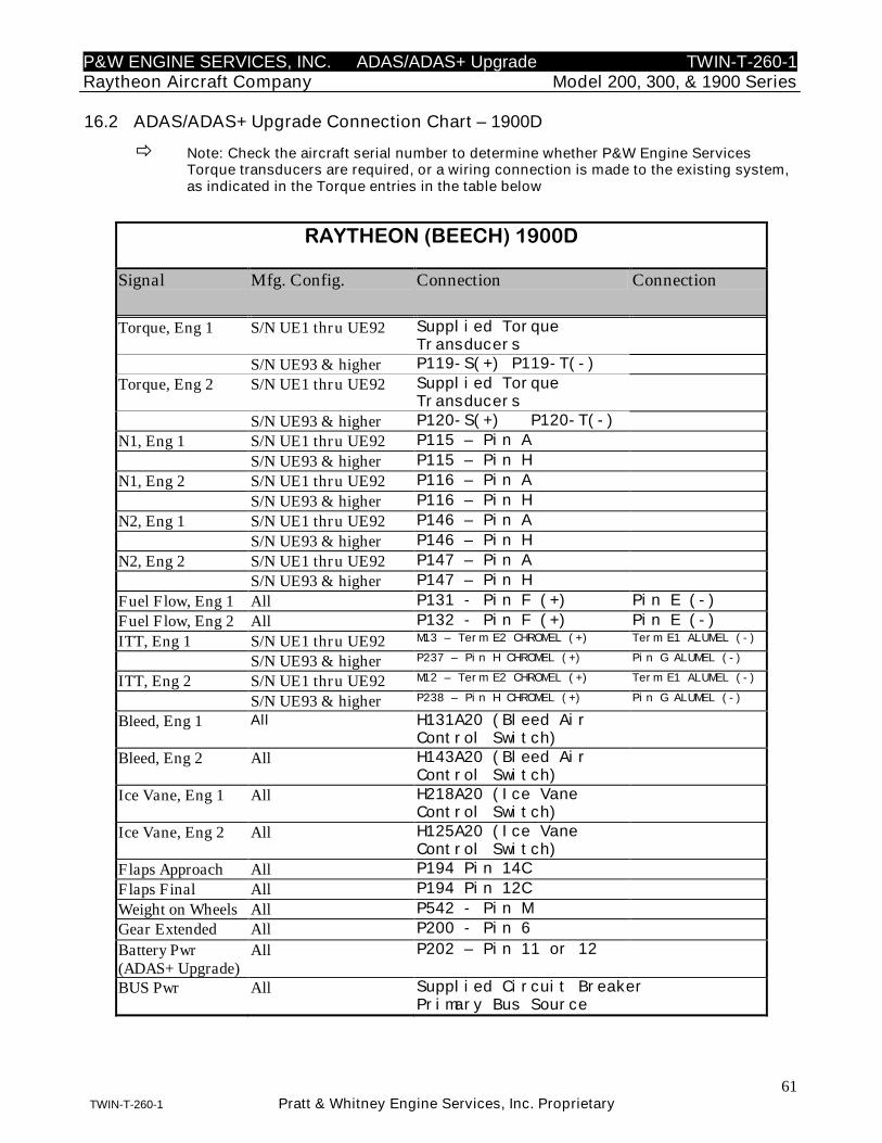
P&W ENGINE SERVICES, INC. ADAS/ADAS+ Upgrade TWIN-T-260-1Raytheon Aircraft Company Model 200, 300, & 1900 Series
61TWIN-T-260-1 Pratt & Whitney Engine Services, Inc. Proprietary
16.2 ADAS/ADAS+ Upgrade Connection Chart – 1900D
Note: Check the aircraft serial number to determine whether P&W Engine ServicesTorque transducers are required, or a wiring connection is made to the existing system,as indicated in the Torque entries in the table below
RAYTHEON (BEECH) 1900D
Signal Mfg. Config. Connection Connection
Torque, Eng 1 S/N UE1 thru UE92 Supplied TorqueTransducers
S/N UE93 & higher P119-S(+) P119-T(-)
Torque, Eng 2 S/N UE1 thru UE92 Supplied TorqueTransducers
S/N UE93 & higher P120-S(+) P120-T(-)
N1, Eng 1 S/N UE1 thru UE92 P115 – Pin A
S/N UE93 & higher P115 – Pin H
N1, Eng 2 S/N UE1 thru UE92 P116 – Pin A
S/N UE93 & higher P116 – Pin H
N2, Eng 1 S/N UE1 thru UE92 P146 – Pin A
S/N UE93 & higher P146 – Pin H
N2, Eng 2 S/N UE1 thru UE92 P147 – Pin A
S/N UE93 & higher P147 – Pin H
Fuel Flow, Eng 1 All P131 - Pin F (+) Pin E (-)
Fuel Flow, Eng 2 All P132 - Pin F (+) Pin E (-)
ITT, Eng 1 S/N UE1 thru UE92 M13 – Term E2 CHROMEL (+) Term E1 ALUMEL (-)
S/N UE93 & higher P237 – Pin H CHROMEL (+) Pin G ALUMEL (-)
ITT, Eng 2 S/N UE1 thru UE92 M12 – Term E2 CHROMEL (+) Term E1 ALUMEL (-)
S/N UE93 & higher P238 – Pin H CHROMEL (+) Pin G ALUMEL (-)
Bleed, Eng 1 All H131A20 (Bleed AirControl Switch)
Bleed, Eng 2 All H143A20 (Bleed AirControl Switch)
Ice Vane, Eng 1 All H218A20 (Ice VaneControl Switch)
Ice Vane, Eng 2 All H125A20 (Ice VaneControl Switch)
Flaps Approach All P194 Pin 14C
Flaps Final All P194 Pin 12C
Weight on Wheels All P542 - Pin M
Gear Extended All P200 - Pin 6
Battery Pwr(ADAS+ Upgrade)
All P202 – Pin 11 or 12
BUS Pwr All Supplied Circuit BreakerPrimary Bus Source
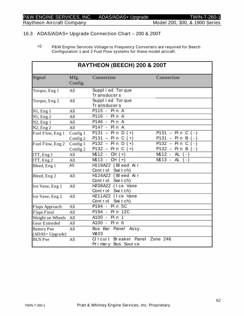
P&W ENGINE SERVICES, INC. ADAS/ADAS+ Upgrade TWIN-T-260-1Raytheon Aircraft Company Model 200, 300, & 1900 Series
62TWIN-T-260-1 Pratt & Whitney Engine Services, Inc. Proprietary
16.3 ADAS/ADAS+ Upgrade Connection Chart – 200 & 200T
P&W Engine Services Voltage to Frequency Converters are required for BeechConfiguration 1 and 2 Fuel Flow systems for these model aircraft.
RAYTHEON (BEECH) 200 & 200T
Signal Mfg.Config.
Connection Connection
Torque, Eng 1 All Supplied TorqueTransducers
Torque, Eng 2 All Supplied TorqueTransducers
N1, Eng 1 All P115 - Pin A
N1, Eng 2 All P116 - Pin A
N2, Eng 1 All P146 - Pin A
N2, Eng 2 All P147 - Pin A
Fuel Flow, Eng 1 Config 1 P131 – Pin D (+) P131 – Pin C (-)
Config 2 P131 – Pin C (+) P131 – Pin B (-)
Fuel Flow, Eng 2 Config 1 P132 – Pin D (+) P132 – Pin C (-)
Config 2 P132 – Pin C (+) P132 – Pin B (-)
ITT, Eng 1 All M112 - CH (+) M112 - AL (-)
ITT, Eng 2 All M113 - CH (+) M113 - AL (-)
Bleed, Eng 1 All H119A22 (Bleed AirControl Switch)
Bleed, Eng 2 All H124A22 (Bleed AirControl Switch)
Ice Vane, Eng 1 All H208A22 (Ice VaneControl Switch)
Ice Vane, Eng 2 All H211A22 (Ice VaneControl Switch)
Flaps Approach All P194 - Pin 5C
Flaps Final All P194 - Pin 12C
Weight on Wheels All A100 - Pin 1
Gear Extended All A100 - Pin 6
Battery Pwr(ADAS+ Upgrade)
All Bus Bar Panel Assy.W103
BUS Pwr All Circuit Breaker Panel Zone 246Primary Bus Source
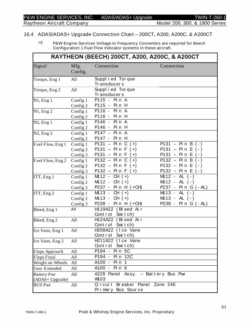
P&W ENGINE SERVICES, INC. ADAS/ADAS+ Upgrade TWIN-T-260-1Raytheon Aircraft Company Model 200, 300, & 1900 Series
63TWIN-T-260-1 Pratt & Whitney Engine Services, Inc. Proprietary
16.4 ADAS/ADAS+ Upgrade Connection Chart – 200CT, A200, A200C, & A200CT
P&W Engine Services Voltage to Frequency Converters are required for BeechConfiguration 1 Fuel Flow Indicator systems in these aircraft.
RAYTHEON (BEECH) 200CT, A200, A200C, & A200CT
Signal Mfg.Config.
Connection Connection
Torque, Eng 1 All Supplied TorqueTransducers
Torque, Eng 2 All Supplied TorqueTransducers
N1, Eng 1 Config 1 P115 - Pin A
Config 2 P115 - Pin H
N1, Eng 2 Config 1 P116 - Pin A
Config 2 P116 - Pin H
N2, Eng 1 Config 1 P146 - Pin A
Config 2 P146 - Pin H
N2, Eng 2 Config 1 P147 - Pin A
Config 2 P147 - Pin H
Fuel Flow, Eng 1 Config 1 P131 – Pin C (+) P131 – Pin B (-)
Config 2 P131 – Pin F (+) P131 – Pin E (-)
Config 3 P131 – Pin F (+) P131 – Pin E (-)
Fuel Flow, Eng 2 Config 1 P132 – Pin C (+) P132 – Pin B (-)
Config 2 P132 – Pin F (+) P132 – Pin E (-)
Config 3 P132 – Pin F (+) P132 – Pin E (-)
ITT, Eng 1 Config 1 M112 - CH (+) M112 - AL (-)
Config 2 M112 - CH (+) M112 - AL (-)
Config 3 P237 - Pin H (+CH) P237 - Pin G (-AL)
ITT, Eng 2 Config 1 M113 - CH (+) M113 - AL (-)
Config 2 M113 - CH (+) M113 - AL (-)
Config 3 P238 - Pin H (+CH) P238 - Pin G (-AL)
Bleed, Eng 1 All H119A22 (Bleed AirControl Switch)
Bleed, Eng 2 All H124A22 (Bleed AirControl Switch)
Ice Vane, Eng 1 All H208A22 (Ice VaneControl Switch)
Ice Vane, Eng 2 All H211A22 (Ice VaneControl Switch)
Flaps Approach All P194 - Pin 5C
Flaps Final All P194 - Pin 12C
Weight on Wheels All A100 - Pin 1
Gear Extended All A100 - Pin 6
Battery Pwr(ADAS+ Upgrade)
All A228 Panel Assy. – Battery Bus PwrW103
BUS Pwr All Circuit Breaker Panel Zone 246Primary Bus Source
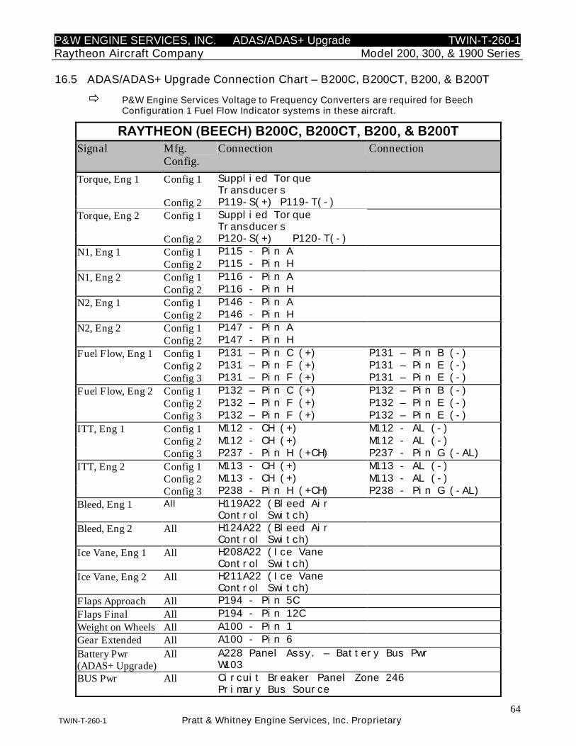
P&W ENGINE SERVICES, INC. ADAS/ADAS+ Upgrade TWIN-T-260-1Raytheon Aircraft Company Model 200, 300, & 1900 Series
64TWIN-T-260-1 Pratt & Whitney Engine Services, Inc. Proprietary
16.5 ADAS/ADAS+ Upgrade Connection Chart – B200C, B200CT, B200, & B200T
P&W Engine Services Voltage to Frequency Converters are required for BeechConfiguration 1 Fuel Flow Indicator systems in these aircraft.
RAYTHEON (BEECH) B200C, B200CT, B200, & B200TSignal Mfg.
Config.Connection Connection
Torque, Eng 1 Config 1 Supplied TorqueTransducers
Config 2 P119-S(+) P119-T(-)
Torque, Eng 2 Config 1 Supplied TorqueTransducers
Config 2 P120-S(+) P120-T(-)
N1, Eng 1 Config 1 P115 - Pin A
Config 2 P115 - Pin H
N1, Eng 2 Config 1 P116 - Pin A
Config 2 P116 - Pin H
N2, Eng 1 Config 1 P146 - Pin A
Config 2 P146 - Pin H
N2, Eng 2 Config 1 P147 - Pin A
Config 2 P147 - Pin H
Fuel Flow, Eng 1 Config 1 P131 – Pin C (+) P131 – Pin B (-)
Config 2 P131 – Pin F (+) P131 – Pin E (-)
Config 3 P131 – Pin F (+) P131 – Pin E (-)
Fuel Flow, Eng 2 Config 1 P132 – Pin C (+) P132 – Pin B (-)
Config 2 P132 – Pin F (+) P132 – Pin E (-)
Config 3 P132 – Pin F (+) P132 – Pin E (-)
ITT, Eng 1 Config 1 M112 - CH (+) M112 - AL (-)
Config 2 M112 - CH (+) M112 - AL (-)
Config 3 P237 - Pin H (+CH) P237 - Pin G (-AL)
ITT, Eng 2 Config 1 M113 - CH (+) M113 - AL (-)
Config 2 M113 - CH (+) M113 - AL (-)
Config 3 P238 - Pin H (+CH) P238 - Pin G (-AL)
Bleed, Eng 1 All H119A22 (Bleed AirControl Switch)
Bleed, Eng 2 All H124A22 (Bleed AirControl Switch)
Ice Vane, Eng 1 All H208A22 (Ice VaneControl Switch)
Ice Vane, Eng 2 All H211A22 (Ice VaneControl Switch)
Flaps Approach All P194 - Pin 5C
Flaps Final All P194 - Pin 12C
Weight on Wheels All A100 - Pin 1
Gear Extended All A100 - Pin 6
Battery Pwr(ADAS+ Upgrade)
All A228 Panel Assy. – Battery Bus PwrW103
BUS Pwr All Circuit Breaker Panel Zone 246Primary Bus Source
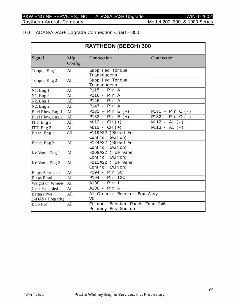
P&W ENGINE SERVICES, INC. ADAS/ADAS+ Upgrade TWIN-T-260-1Raytheon Aircraft Company Model 200, 300, & 1900 Series
65TWIN-T-260-1 Pratt & Whitney Engine Services, Inc. Proprietary
16.6 ADAS/ADAS+ Upgrade Connection Chart – 300
RAYTHEON (BEECH) 300
Signal Mfg.Config.
Connection Connection
Torque, Eng 1 All Supplied TorqueTransducers
Torque, Eng 2 All Supplied TorqueTransducers
N1, Eng 1 All P115 - Pin A
N1, Eng 2 All P116 - Pin A
N2, Eng 1 All P146 - Pin A
N2, Eng 2 All P147 - Pin A
Fuel Flow, Eng 1 All P131 – Pin E (+) P131 – Pin C (-)
Fuel Flow, Eng 2 All P132 – Pin E (+) P132 – Pin C (-)
ITT, Eng 1 All M112 - CH (+) M112 - AL (-)
ITT, Eng 2 All M113 - CH (+) M113 - AL (-)
Bleed, Eng 1 All H119A22 (Bleed AirControl Switch)
Bleed, Eng 2 All H124A22 (Bleed AirControl Switch)
Ice Vane, Eng 1 All H208A22 (Ice VaneControl Switch)
Ice Vane, Eng 2 All H211A22 (Ice VaneControl Switch)
Flaps Approach All P194 - Pin 5C
Flaps Final All P194 - Pin 12C
Weight on Wheels All A100 - Pin 1
Gear Extended All A100 - Pin 6
Battery Pwr(ADAS+ Upgrade)
All A1 Circuit Breaker Box Assy.W1
BUS Pwr All Circuit Breaker Panel Zone 246Primary Bus Source
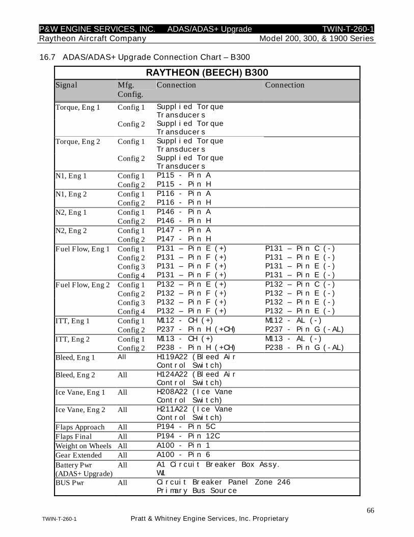
P&W ENGINE SERVICES, INC. ADAS/ADAS+ Upgrade TWIN-T-260-1Raytheon Aircraft Company Model 200, 300, & 1900 Series
66TWIN-T-260-1 Pratt & Whitney Engine Services, Inc. Proprietary
16.7 ADAS/ADAS+ Upgrade Connection Chart – B300
RAYTHEON (BEECH) B300Signal Mfg.
Config.Connection Connection
Torque, Eng 1 Config 1 Supplied TorqueTransducers
Config 2 Supplied TorqueTransducers
Torque, Eng 2 Config 1 Supplied TorqueTransducers
Config 2 Supplied TorqueTransducers
N1, Eng 1 Config 1 P115 - Pin A
Config 2 P115 - Pin H
N1, Eng 2 Config 1 P116 - Pin A
Config 2 P116 - Pin H
N2, Eng 1 Config 1 P146 - Pin A
Config 2 P146 - Pin H
N2, Eng 2 Config 1 P147 - Pin A
Config 2 P147 - Pin H
Fuel Flow, Eng 1 Config 1 P131 – Pin E (+) P131 – Pin C (-)
Config 2 P131 – Pin F (+) P131 – Pin E (-)
Config 3 P131 – Pin F (+) P131 – Pin E (-)
Config 4 P131 – Pin F (+) P131 – Pin E (-)
Fuel Flow, Eng 2 Config 1 P132 – Pin E (+) P132 – Pin C (-)
Config 2 P132 – Pin F (+) P132 – Pin E (-)
Config 3 P132 – Pin F (+) P132 – Pin E (-)
Config 4 P132 – Pin F (+) P132 – Pin E (-)
ITT, Eng 1 Config 1 M112 - CH (+) M112 - AL (-)
Config 2 P237 - Pin H (+CH) P237 - Pin G (-AL)
ITT, Eng 2 Config 1 M113 - CH (+) M113 - AL (-)
Config 2 P238 - Pin H (+CH) P238 - Pin G (-AL)
Bleed, Eng 1 All H119A22 (Bleed AirControl Switch)
Bleed, Eng 2 All H124A22 (Bleed AirControl Switch)
Ice Vane, Eng 1 All H208A22 (Ice VaneControl Switch)
Ice Vane, Eng 2 All H211A22 (Ice VaneControl Switch)
Flaps Approach All P194 - Pin 5C
Flaps Final All P194 - Pin 12C
Weight on Wheels All A100 - Pin 1
Gear Extended All A100 - Pin 6
Battery Pwr(ADAS+ Upgrade)
All A1 Circuit Breaker Box Assy.W1
BUS Pwr All Circuit Breaker Panel Zone 246Primary Bus Source
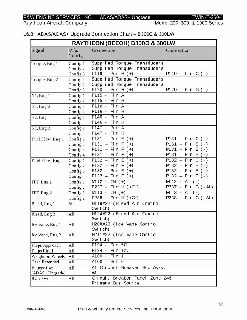
P&W ENGINE SERVICES, INC. ADAS/ADAS+ Upgrade TWIN-T-260-1Raytheon Aircraft Company Model 200, 300, & 1900 Series
67TWIN-T-260-1 Pratt & Whitney Engine Services, Inc. Proprietary
16.8 ADAS/ADAS+ Upgrade Connection Chart – B300C & 300LW
RAYTHEON (BEECH) B300C & 300LWSignal Mfg.
Config.Connection Connection
Torque, Eng 1 Config 1 Supplied Torque Transducers
Config 2 Supplied Torque Transducers
Config 3 P119 - Pin H (+) P119 - Pin G (-)
Torque, Eng 2 Config 1 Supplied Torque Transducers
Config 2 Supplied Torque Transducers
Config 3 P120 – Pin H (+) P120 – Pin G (-)
N1, Eng 1 Config 1 P115 - Pin A
Config 2 P115 - Pin H
N1, Eng 2 Config 1 P116 - Pin A
Config 2 P116 - Pin H
N2, Eng 1 Config 1 P146 - Pin A
Config 2 P146 - Pin H
N2, Eng 2 Config 1 P147 - Pin A
Config 2 P147 - Pin H
Fuel Flow, Eng 1 Config 1 P131 – Pin E (+) P131 – Pin C (-)
Config 2 P131 – Pin F (+) P131 – Pin E (-)
Config 3 P131 – Pin F (+) P131 – Pin E (-)
Config 4 P131 – Pin F (+) P131 – Pin E (-)
Fuel Flow, Eng 2 Config 1 P132 – Pin E (+) P132 – Pin C (-)
Config 2 P132 – Pin F (+) P132 – Pin E (-)
Config 3 P132 – Pin F (+) P132 – Pin E (-)
Config 4 P132 – Pin F (+) P132 – Pin E (-)
ITT, Eng 1 Config 1 M112 - CH (+) M112 - AL (-)
Config 2 P237 - Pin H (+CH) P237 - Pin G (-AL)
ITT, Eng 2 Config 1 M113 - CH (+) M113 - AL (-)
Config 2 P238 - Pin H (+CH) P238 - Pin G (-AL)
Bleed, Eng 1 All H119A22 (Bleed Air ControlSwitch)
Bleed, Eng 2 All H124A22 (Bleed Air ControlSwitch)
Ice Vane, Eng 1 All H208A22 (Ice Vane ControlSwitch)
Ice Vane, Eng 2 All H211A22 (Ice Vane ControlSwitch)
Flaps Approach All P194 - Pin 5C
Flaps Final All P194 - Pin 12C
Weight on Wheels All A100 - Pin 1
Gear Extended All A100 - Pin 6
Battery Pwr(ADAS+ Upgrade)
All A1 Circuit Breaker Box Assy.W1
BUS Pwr All Circuit Breaker Panel Zone 246Primary Bus Source
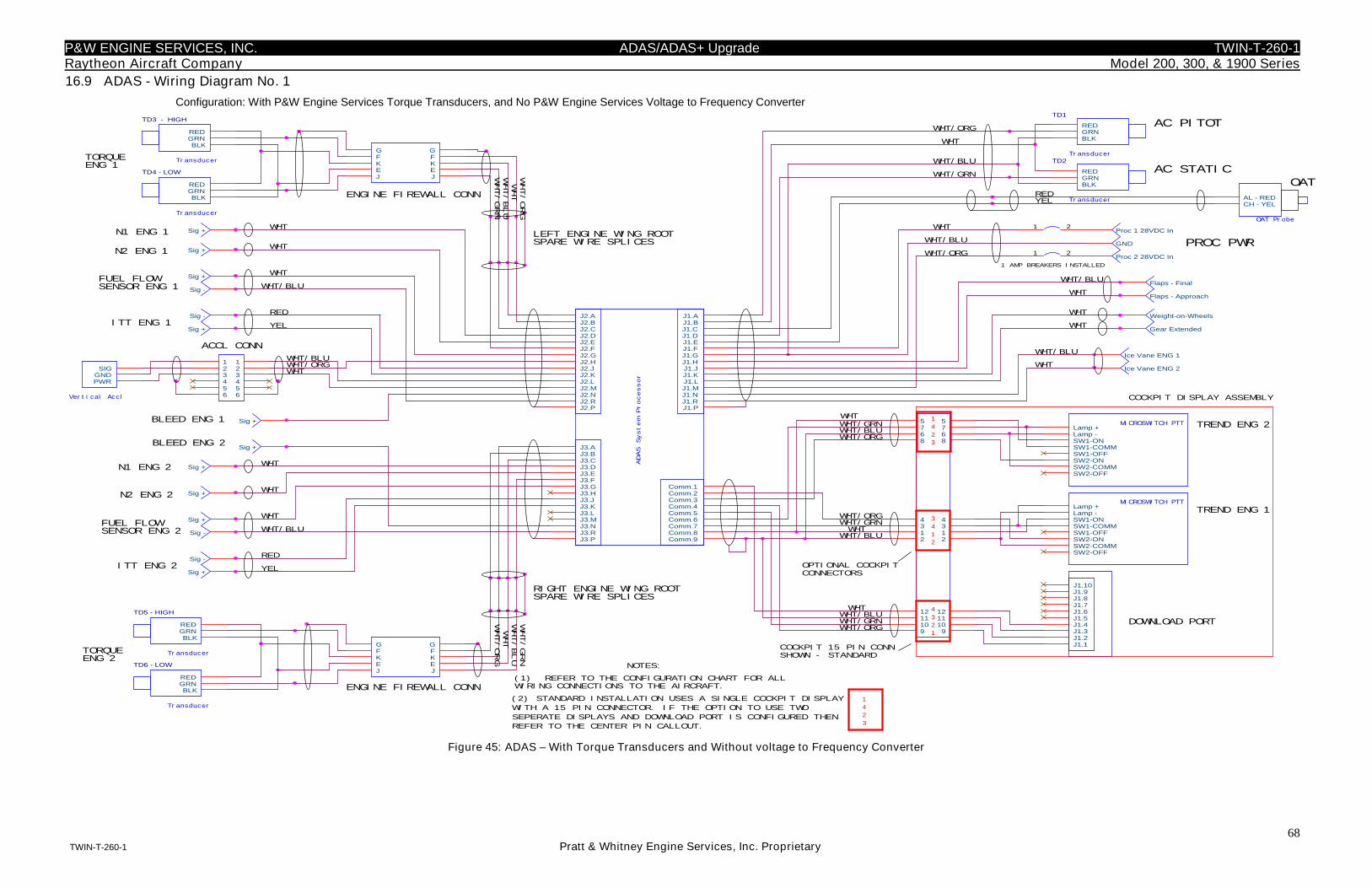
P&W ENGINE SERVICES, INC. ADAS/ADAS+ Upgrade TWIN-T-260-1Raytheon Aircraft Company Model 200, 300, & 1900 Series
68TWIN-T-260-1 Pratt & Whitney Engine Services, Inc. Proprietary
16.9 ADAS - Wiring Diagram No. 1
Configuration: With P&W Engine Services Torque Transducers, and No P&W Engine Services Voltage to Frequency Converter
Transducer
TD2
RED
BLKGRN
Transducer
TD1
RED
BLKGRN
Transducer
TD4 - LOW
RED
BLKGRN
Sig +
Sig -
Sig +
Sig -
Sig +
Sig +
Transducer
TD3 - HIGH
RED
BLKGRN
Sig +
Sig +
Sig +
Sig -
Sig +
Sig -
Transducer
TD6 - LOW
RED
BLKGRN
Transducer
TD5 - HIGH
RED
BLKGRN
GFKEJ
GFKEJ
GFKEJ
GFKEJ
Weight-on-Wheels
Gear Extended
Sig +
Sig +
Proc 1 28VDC In
GND
Proc 2 28VDC In
OAT Probe
AL - REDCH - YEL
J1.1J1.2J1.3J1.4J1.5J1.6J1.7J1.8J1.9J1.10
MICROSWITCH PTTLamp +Lamp -SW1-ONSW1-COMMSW1-OFFSW2-ONSW2-COMMSW2-OFF
MICROSWITCH PTTLamp +Lamp -SW1-ONSW1-COMMSW1-OFFSW2-ONSW2-COMMSW2-OFF
1 2
1 2
123456
123456Vertical Accl
SIG
PWRGND
ADAS
System
Processor
J1.AJ1.BJ1.C
J1.L
J1.DJ1.EJ1.FJ1.GJ1.HJ1.JJ1.K
J1.MJ1.NJ1.RJ1.P
Comm.1Comm.2Comm.3Comm.4Comm.5Comm.6Comm.7Comm.8Comm.9
J3.AJ3.BJ3.CJ3.DJ3.EJ3.FJ3.GJ3.HJ3.JJ3.KJ3.LJ3.MJ3.NJ3.RJ3.P
J2.AJ2.BJ2.CJ2.DJ2.EJ2.FJ2.GJ2.HJ2.JJ2.KJ2.LJ2.MJ2.NJ2.RJ2.P
68
75
9
68
75
9
12
34
12
34
101112
101112
Flaps - Approach
Flaps - Final
Ice Vane ENG 1
Ice Vane ENG 2
1
4
2
3
(1) REFER TO THE CONFIGURATION CHART FOR ALLWIRING CONNECTIONS TO THE AIRCRAFT.
(2) STANDARD INSTALLATION USES A SINGLE COCKPIT DISPLAY
WITH A 15 PIN CONNECTOR. IF THE OPTION TO USE TWO
SEPERATE DISPLAYS AND DOWNLOAD PORT IS CONFIGURED THEN
REFER TO THE CENTER PIN CALLOUT.
NOTES:
TORQUEENG 1
TREND ENG 1
TREND ENG 2
DOWNLOAD PORT
TORQUEENG 2
N1 ENG 1
N2 ENG 1
FUEL FLOWSENSOR ENG 1
ITT ENG 1
N1 ENG 2
N2 ENG 2
AC PITOT
AC STATIC
ENGINE FIREWALL CONN
LEFT ENGINE WING ROOTSPARE WIRE SPLICES
ITT ENG 2
RIGHT ENGINE WING ROOTSPARE WIRE SPLICES
ENGINE FIREWALL CONN
FUEL FLOWSENSOR ENG 2
WHT/ORG
WHT/BLU
WHT/GRN
WHT
WHT/ORG
WHT/GRN
WHT/BLU
WHT
WHT/ORGWHT/BLU
WHT
WHT/BLU
RED
YEL
WHT
WHT
WHT
WHT
WHT
WHT
WHT/BLU
RED
YEL
WHT/ORG
WHT
WHT/BLU
WHT/GRN
REDYEL
WHT/BLU
WHT
WHT
WHT
COCKPIT 15 PIN CONNSHOWN - STANDARD
WHT/ORG
WHT/GRNWHT
WHT/BLU
WHT/ORGWHT/GRNWHT
WHT/BLU
WHT/BLUWHT
WHT/GRNWHT/ORG
BLEED ENG 1
1 AMP BREAKERS INSTALLED
WHT
WHT/ORG
WHT/BLU
3
4
1
2
4
3
2
1
1
4
2
3
OPTIONAL COCKPITCONNECTORS
COCKPIT DISPLAY ASSEMBLY
OAT
BLEED ENG 2
WHT/BLU
WHT
ACCL CONN
PROC PWR
Figure 45: ADAS – With Torque Transducers and Without voltage to Frequency Converter
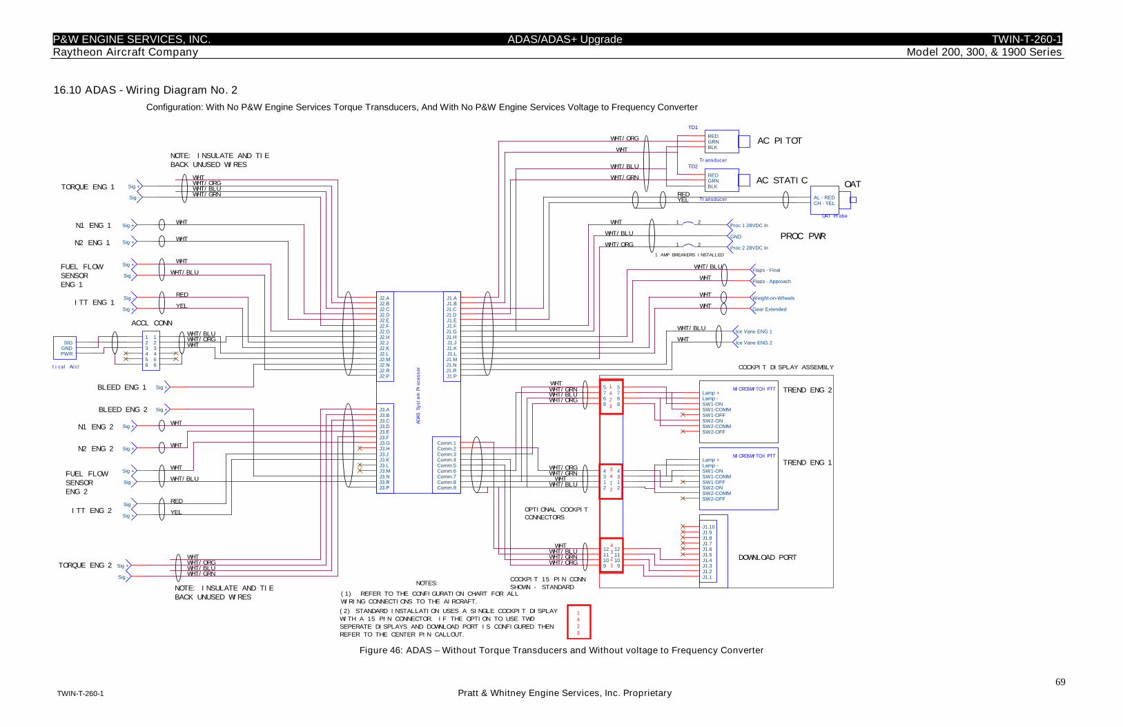
P&W ENGINE SERVICES, INC. ADAS/ADAS+ Upgrade TWIN-T-260-1Raytheon Aircraft Company Model 200, 300, & 1900 Series
69TWIN-T-260-1 Pratt & Whitney Engine Services, Inc. Proprietary
16.10 ADAS - Wiring Diagram No. 2
Configuration: With No P&W Engine Services Torque Transducers, And With No P&W Engine Services Voltage to Frequency Converter
PROC PWR
NOTE: INSULATE AND TIEBACK UNUSED WIRES
1
4
2
3
3
4
1
2
Sig +
Sig -
Transducer
TD1
RED
BLKGRN
Transducer
TD2
RED
BLKGRN
Sig +
Sig +
Sig +
Sig +
Sig -
Flaps - Approach
Flaps - FinalSig +
Sig -
Sig +
Sig -
Sig + Proc 1 28VDC In
GND
Proc 2 28VDC In
Sig +
Sig +
Weight-on-Wheels
Gear Extended
Ice Vane ENG 1
Ice Vane ENG 2
OAT Probe
AL - REDCH - YEL
68
75
9
68
75
9
12
34
12
34
101112
101112
J1.1J1.2J1.3J1.4J1.5J1.6J1.7J1.8J1.9J1.10
1 2
1 2
MICROSWITCH PTTLamp +Lamp -SW1-ONSW1-COMMSW1-OFFSW2-ONSW2-COMMSW2-OFF
MICROSWITCH PTTLamp +Lamp -SW1-ONSW1-COMMSW1-OFFSW2-ONSW2-COMMSW2-OFF
Sig +
Sig -
Vertical Accl
SIG
PWRGND
ADASSystemProcessor
J1.AJ1.BJ1.C
J1.L
J1.DJ1.EJ1.FJ1.GJ1.HJ1.JJ1.K
J1.MJ1.NJ1.RJ1.P
Comm.1Comm.2Comm.3Comm.4Comm.5Comm.6Comm.7Comm.8Comm.9
J3.AJ3.BJ3.CJ3.DJ3.EJ3.FJ3.GJ3.HJ3.JJ3.KJ3.LJ3.MJ3.NJ3.RJ3.P
J2.AJ2.BJ2.CJ2.DJ2.EJ2.FJ2.GJ2.HJ2.JJ2.KJ2.LJ2.MJ2.NJ2.RJ2.P
123456
123456
Sig +
Sig -
TORQUE ENG 1
DOWNLOAD PORT
TREND ENG 2
TREND ENG 1
FUEL FLOWSENSORENG 1
N2 ENG 1
N1 ENG 1
N1 ENG 2
ITT ENG 1
AC STATIC
AC PITOT
N2 ENG 2
WHT/ORG
FUEL FLOWSENSORENG 2
ITT ENG 2
WHT
WHT/BLU
YEL
RED
WHT/BLU
WHT
WHT
WHT
WHT
WHT
RED
WHT/BLU
WHT
WHT
WHT/ORG
YEL
WHT/GRN
WHT/BLU
YELRED
WHT
WHT/BLU
WHT
WHT
COCKPIT 15 PIN CONN
SHOWN - STANDARD
WHTWHT/GRN
WHT/ORG
WHT/ORG
WHT/BLU
WHT/BLUWHT
WHT/GRN
WHT/GRN
WHTWHT/BLU
BLEED ENG 1
WHT/ORG
WHT
1 AMP BREAKERS INSTALLED
WHT/ORG
WHT/BLU
OPTIONAL COCKPIT
CONNECTORS
1
4
2
3
4
3
2
1
(2) STANDARD INSTALLATION USES A SINGLE COCKPIT DISPLAY
WITH A 15 PIN CONNECTOR. IF THE OPTION TO USE TWO
SEPERATE DISPLAYS AND DOWNLOAD PORT IS CONFIGURED THEN
REFER TO THE CENTER PIN CALLOUT.
OAT
COCKPIT DISPLAY ASSEMBLY
BLEED ENG 2
NOTES:
WHT/BLUACCL CONN
WHT
WHT/BLUWHT/ORG
WHT/GRN
NOTE: INSULATE AND TIEBACK UNUSED WIRES
WHT
WHT/ORG
WHT/GRN
TORQUE ENG 2WHT
WHT/BLU
(1) REFER TO THE CONFIGURATION CHART FOR ALL
WIRING CONNECTIONS TO THE AIRCRAFT.
Figure 46: ADAS – Without Torque Transducers and Without voltage to Frequency Converter
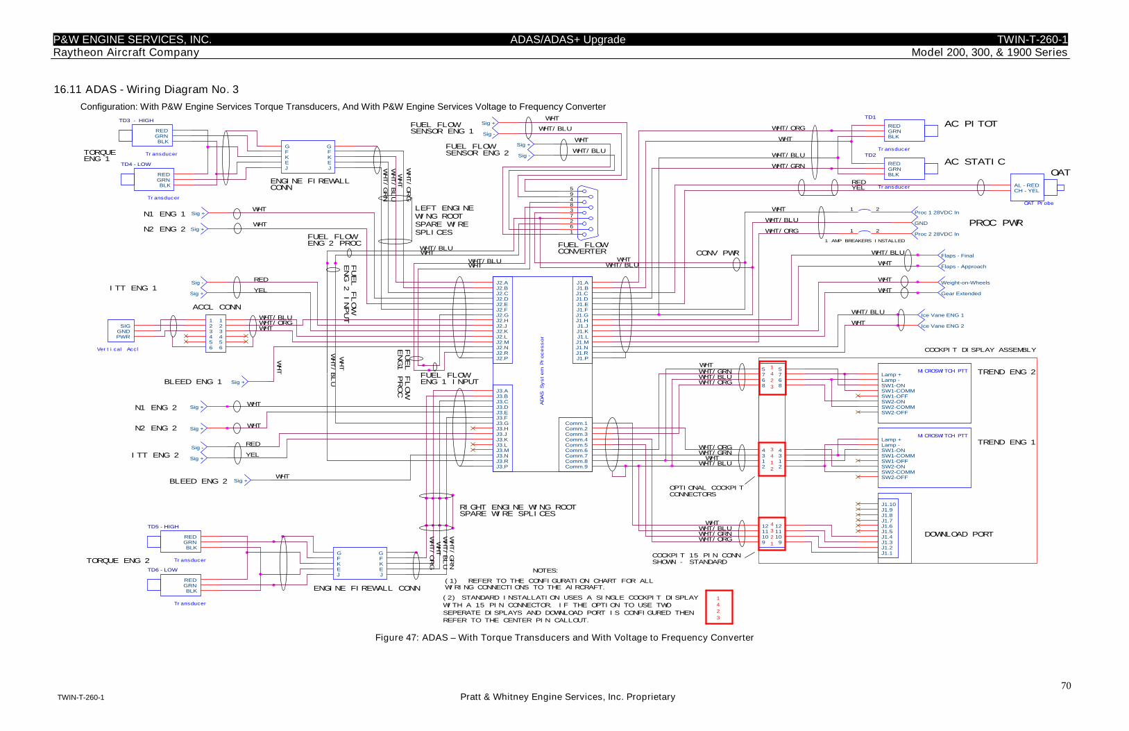
P&W ENGINE SERVICES, INC. ADAS/ADAS+ Upgrade TWIN-T-260-1Raytheon Aircraft Company Model 200, 300, & 1900 Series
70TWIN-T-260-1 Pratt & Whitney Engine Services, Inc. Proprietary
16.11 ADAS - Wiring Diagram No. 3
Configuration: With P&W Engine Services Torque Transducers, And With P&W Engine Services Voltage to Frequency Converter
Transducer
TD4 - LOW
RED
BLKGRN
Sig +
Sig -
Transducer
TD3 - HIGH
RED
BLKGRN
Sig +
Sig +
Sig -
Transducer
TD6 - LOW
RED
BLKGRN
Transducer
TD5 - HIGH
RED
BLKGRN
GFKEJ
GFKEJ
Weight-on-Wheels
Gear Extended
OAT Probe
AL - REDCH - YEL
J1.1J1.2J1.3J1.4J1.5J1.6J1.7J1.8J1.9J1.10
MICROSWITCH PTTLamp +Lamp -SW1-ONSW1-COMMSW1-OFFSW2-ONSW2-COMMSW2-OFF
MICROSWITCH PTTLamp +Lamp -SW1-ONSW1-COMMSW1-OFFSW2-ONSW2-COMMSW2-OFF
1 2
68
75
9
68
75
9
12
34
12
34
101112
101112
Flaps - Approach
Flaps - Final
Sig +
Sig -
Sig +
Sig -
Sig +
Sig +
1 2
594837261
Transducer
TD1
RED
BLKGRN
Transducer
TD2
RED
BLKGRN
Proc 1 28VDC In
GND
Proc 2 28VDC In
Ice Vane ENG 1
Ice Vane ENG 2
Sig +
Sig +
Sig +
GFKEJ
GFKEJ
ADASSystemProcessor
J1.AJ1.BJ1.C
J1.L
J1.DJ1.EJ1.FJ1.GJ1.HJ1.JJ1.K
J1.MJ1.NJ1.RJ1.P
Comm.1Comm.2Comm.3Comm.4Comm.5Comm.6Comm.7Comm.8Comm.9
J3.AJ3.BJ3.CJ3.DJ3.EJ3.FJ3.GJ3.HJ3.JJ3.KJ3.LJ3.MJ3.NJ3.RJ3.P
J2.AJ2.BJ2.CJ2.DJ2.EJ2.FJ2.GJ2.HJ2.JJ2.KJ2.LJ2.MJ2.NJ2.RJ2.P
123456
123456Vertical Accl
SIG
PWRGND
1
4
2
3
(1) REFER TO THE CONFIGURATION CHART FOR ALLWIRING CONNECTIONS TO THE AIRCRAFT.
(2) STANDARD INSTALLATION USES A SINGLE COCKPIT DISPLAY
WITH A 15 PIN CONNECTOR. IF THE OPTION TO USE TWO
SEPERATE DISPLAYS AND DOWNLOAD PORT IS CONFIGURED THEN
REFER TO THE CENTER PIN CALLOUT.
NOTES:
TORQUEENG 1
TREND ENG 1
TREND ENG 2
DOWNLOAD PORT
TORQUE ENG 2
N1 ENG 1
N2 ENG 2
FUEL FLOWSENSOR ENG 1
ITT ENG 1
N2 ENG 2
AC PITOT
AC STATIC
ENGINE FIREWALLCONN
ITT ENG 2
RIGHT ENGINE WING ROOTSPARE WIRE SPLICES
ENGINE FIREWALL CONN
WHT/ORG
WHT/BLU
WHT/GRN
WHT
WHT/ORG
WHT/GRN
WHT/BLU
WHT
WHT/ORG
RED
YEL
WHT
WHT
WHT
WHT/BLU
WHT/ORG
WHT
WHT/BLU
WHT/GRN
REDYEL
WHT/BLU
WHT
WHT
WHT
COCKPIT 15 PIN CONNSHOWN - STANDARD
WHT/ORG
WHT/GRNWHT
WHT/BLU
WHT/ORGWHT/GRNWHT
WHT/BLU
WHT/BLUWHT
WHT/GRNWHT/ORG
BLEED ENG 1
1 AMP BREAKERS INSTALLED
WHT
WHT/ORG
WHT/BLU
3
4
1
2
4
3
2
1
1
4
2
3
OPTIONAL COCKPITCONNECTORS
COCKPIT DISPLAY ASSEMBLY
OAT
BLEED ENG 2
WHT/BLU
WHT
WHT/BLU
WHT
FUEL FLOWCONVERTER
FUEL FLOWSENSOR ENG 2
WHT
WHT
N1 ENG 2
WHT
WHT/BLU
WHT WHT/BLUWHT
WHT
WHT
YEL
RED
WHTWHT/BLU
LEFT ENGINEWING ROOTSPARE WIRESPLICES
FUEL FLOWENG 2 PROC
WHT/BLUFUEL
FLOW
ENG
2INPUT
FUEL
FLOW
ENG1
PROC
FUEL FLOWENG 1 INPUT
CONV PWR
WHT/BLU
ACCL CONN
WHT
PROC PWR
Figure 47: ADAS – With Torque Transducers and With Voltage to Frequency Converter
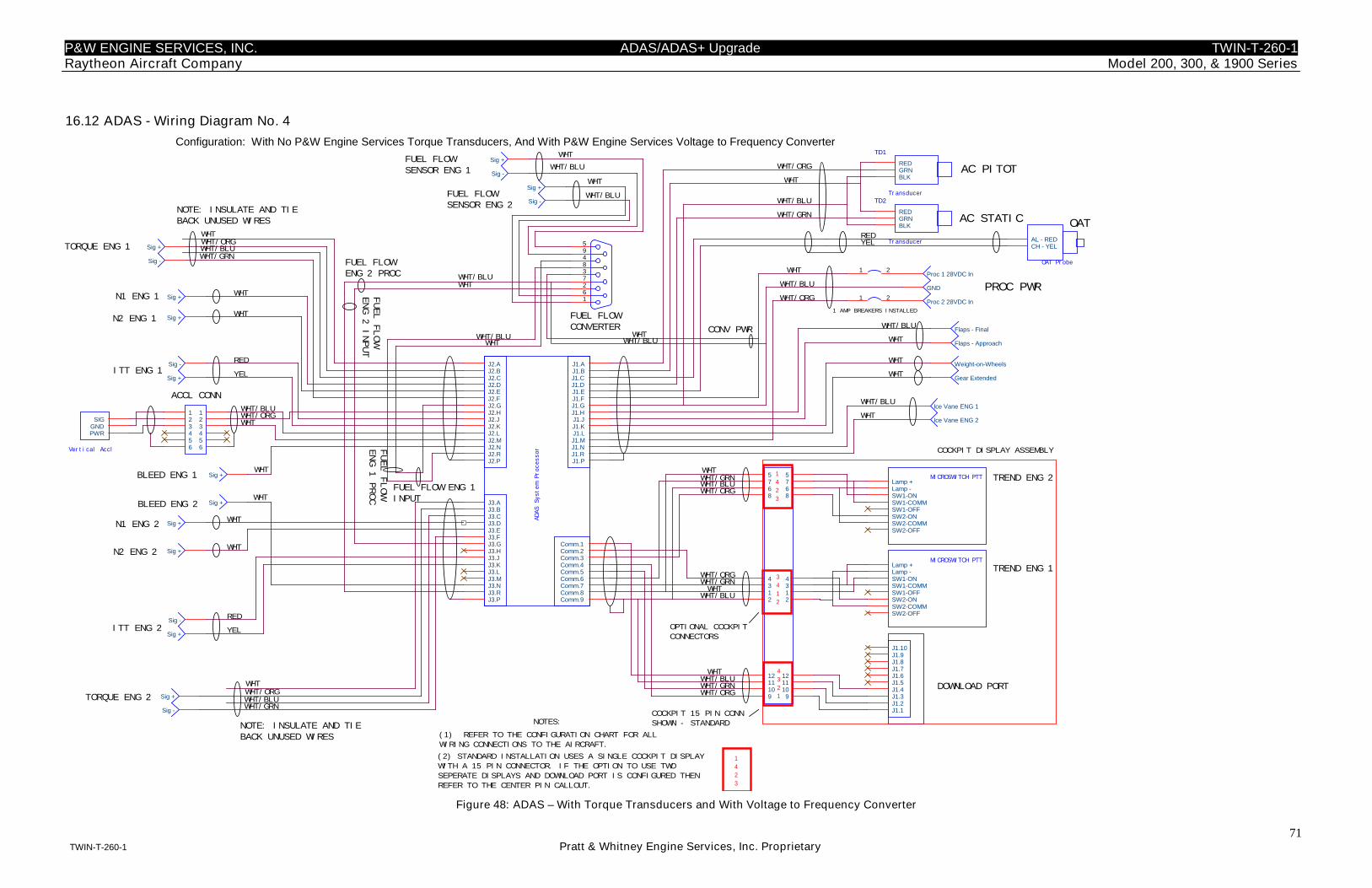
P&W ENGINE SERVICES, INC. ADAS/ADAS+ Upgrade TWIN-T-260-1Raytheon Aircraft Company Model 200, 300, & 1900 Series
71TWIN-T-260-1 Pratt & Whitney Engine Services, Inc. Proprietary
16.12 ADAS - Wiring Diagram No. 4
Configuration: With No P&W Engine Services Torque Transducers, And With P&W Engine Services Voltage to Frequency Converter
Sig +
Sig -
Transducer
TD1
RED
BLKGRN
Transducer
TD2
RED
BLKGRN
Sig +
Sig +
Sig +
Flaps - Approach
Flaps - Final
Sig +
Sig -
Sig +
Proc 1 28VDC In
GND
Proc 2 28VDC In
Sig +
Sig +
Weight-on-Wheels
Gear Extended
MICROSWITCH PTTLamp +Lamp -SW1-ONSW1-COMMSW1-OFFSW2-ONSW2-COMMSW2-OFF
J1.1J1.2J1.3J1.4J1.5J1.6J1.7J1.8J1.9J1.10
Ice Vane ENG 1
Ice Vane ENG 2
OAT Probe
AL - REDCH - YEL
1 2
1 2
Vertical Accl
SIG
PWRGND
123456
123456
68
75
9
68
75
9
12
34
12
34
101112
101112
MICROSWITCH PTTLamp +Lamp -SW1-ONSW1-COMMSW1-OFFSW2-ONSW2-COMMSW2-OFF
Sig +
Sig -
Sig +
Sig -
ADAS
System
Processor
J1.AJ1.BJ1.C
J1.L
J1.DJ1.EJ1.FJ1.GJ1.HJ1.JJ1.K
J1.MJ1.NJ1.RJ1.P
Comm.1Comm.2Comm.3Comm.4Comm.5Comm.6Comm.7Comm.8Comm.9
J3.AJ3.BJ3.CJ3.DJ3.EJ3.FJ3.GJ3.HJ3.JJ3.KJ3.LJ3.MJ3.NJ3.RJ3.P
J2.AJ2.BJ2.CJ2.DJ2.EJ2.FJ2.GJ2.HJ2.JJ2.KJ2.LJ2.MJ2.NJ2.RJ2.P
TORQUE ENG 1
FUEL
FLOW
ENG
1PROC
FUEL FLOW ENG 1INPUT
N1 ENG 1
TREND ENG 2
TREND ENG 1
N2 ENG 1
DOWNLOAD PORT
ITT ENG 1
AC PITOT
N2 ENG 2
N1 ENG 2
ITT ENG 2
AC STATIC
WHT/BLUWHT/ORG
RED
WHT
WHT
YEL
WHT
WHT
WHT
WHT/ORG
YEL
RED
WHT/BLU
WHT
YELRED
WHT/GRN
WHT
WHT
WHT
WHT/BLU
WHT/BLUWHT/GRN
COCKPIT 15 PIN CONN
SHOWN - STANDARD
WHT
WHT/ORG
WHTWHT/GRN
WHT/ORG
WHT/GRNWHT/ORG
WHT/BLU
WHT/BLUWHT
WHT/GRN
WHTWHT/BLU
1 AMP BREAKERS INSTALLED
BLEED ENG 1
WHT/ORG
PROC PWRWHT/ORG
WHT
1
4
2
3
4
3
2
1
WHT/BLU
OAT
COCKPIT DISPLAY ASSEMBLY
OPTIONAL COCKPIT
CONNECTORS
BLEED ENG 2
(2) STANDARD INSTALLATION USES A SINGLE COCKPIT DISPLAY
WITH A 15 PIN CONNECTOR. IF THE OPTION TO USE TWO
SEPERATE DISPLAYS AND DOWNLOAD PORT IS CONFIGURED THEN
REFER TO THE CENTER PIN CALLOUT.
WHT
WHT/BLU
NOTES:
WHT/ORG
WHT/GRN
ACCL CONN
WHT
WHT/BLU
TORQUE ENG 2
(1) REFER TO THE CONFIGURATION CHART FOR ALL
WIRING CONNECTIONS TO THE AIRCRAFT.
3
4
1
2
1
4
2
3
NOTE: INSULATE AND TIEBACK UNUSED WIRES
594837261
Sig +
Sig -
Sig +
Sig -
FUEL FLOWSENSOR ENG 1 WHT/BLU
WHT/BLU
WHT
WHT
FUEL FLOWSENSOR ENG 2
FUEL FLOWCONVERTER
WHT/BLU
WHT/BLU
WHTWHT
WHT
WHT/BLU
WHT
WHT
NOTE: INSULATE AND TIEBACK UNUSED WIRES
CONV PWR
FUEL
FLOW
ENG
2INPUT
FUEL FLOWENG 2 PROC
Figure 48: ADAS – With Torque Transducers and With Voltage to Frequency Converter
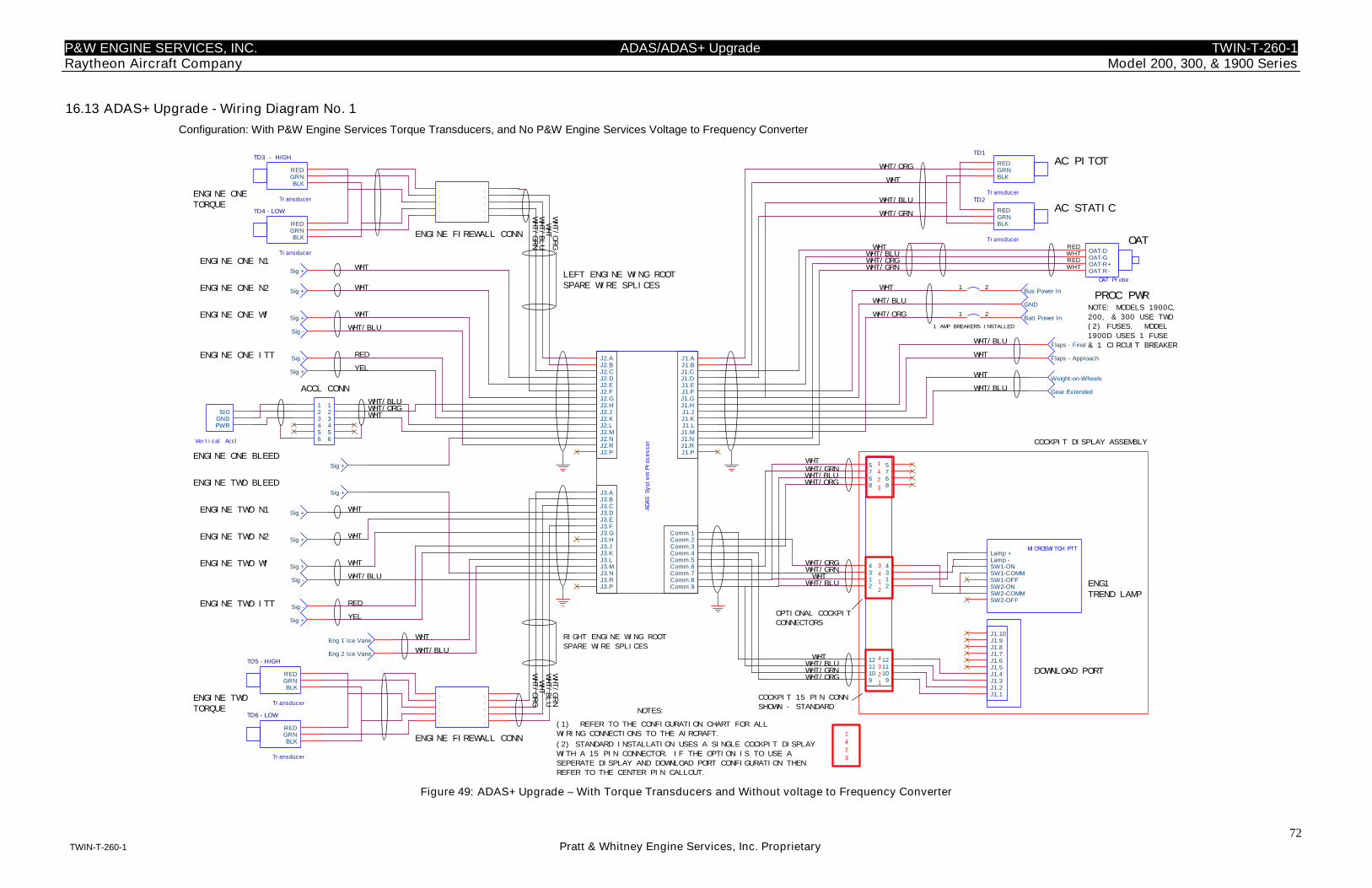
P&W ENGINE SERVICES, INC. ADAS/ADAS+ Upgrade TWIN-T-260-1Raytheon Aircraft Company Model 200, 300, & 1900 Series
72TWIN-T-260-1 Pratt & Whitney Engine Services, Inc. Proprietary
16.13 ADAS+ Upgrade - Wiring Diagram No. 1
Configuration: With P&W Engine Services Torque Transducers, and No P&W Engine Services Voltage to Frequency Converter
LEFT ENGINE WING ROOTSPARE WIRE SPLICES
ENGINE FIREWALL CONN
ENGINE FIREWALL CONN
RIGHT ENGINE WING ROOT
SPARE WIRE SPLICES
Transducer
TD4 - LOW
RED
BLKGRN
Transducer
TD1
RED
BLKGRN
Transducer
TD2
RED
BLKGRN
Sig +
Sig -
Sig +
Sig -
Sig +
Transducer
TD3 - HIGH
RED
BLKGRN
Sig +
Sig +
Sig -
Sig +
Sig +
Transducer
TD6 - LOW
RED
BLKGRN
Sig +
Sig -
.
.
.
.
.
.
.
.
.
.
.
.
.
.
.
.
.
.
.
.
Transducer
TD5 - HIGH
RED
BLKGRN
Sig +
Weight-on-Wheels
Gear Extended
Flaps - Approach
Flaps - Final
J1.1J1.2J1.3J1.4J1.5J1.6J1.7J1.8J1.9J1.10
Sig +
MICROSWITCH PTTLamp +Lamp -SW1-ONSW1-COMMSW1-OFFSW2-ONSW2-COMMSW2-OFF
1 2
1 2
68
75
9
68
75
9
12
34
12
34
101112
101112
Vertical Accl
SIG
PWRGND
123456
123456
Eng 1 Ice Vane
Eng 2 Ice VaneADAS
System
Processor
J1.AJ1.BJ1.C
J1.L
J1.DJ1.EJ1.FJ1.GJ1.HJ1.JJ1.K
J1.MJ1.NJ1.RJ1.P
Comm.1Comm.2Comm.3Comm.4Comm.5Comm.6Comm.7Comm.8Comm.9
J3.AJ3.BJ3.CJ3.DJ3.EJ3.FJ3.GJ3.HJ3.JJ3.KJ3.LJ3.MJ3.NJ3.RJ3.P
J2.AJ2.BJ2.CJ2.DJ2.EJ2.FJ2.GJ2.HJ2.JJ2.KJ2.LJ2.MJ2.NJ2.RJ2.P
Bus Power In
GND
Batt Power In
OAT Probe
OAT-GWHT
OAT-R+RED
OAT-DRED
OAT R-WHT
WHT
WHT/BLU
(2) STANDARD INSTALLATION USES A SINGLE COCKPIT DISPLAY
WITH A 15 PIN CONNECTOR. IF THE OPTION IS TO USE A
SEPERATE DISPLAY AND DOWNLOAD PORT CONFIGURATION THEN
REFER TO THE CENTER PIN CALLOUT.
COCKPIT 15 PIN CONN
SHOWN - STANDARDNOTES:
(1) REFER TO THE CONFIGURATION CHART FOR ALL
WIRING CONNECTIONS TO THE AIRCRAFT.
NOTE: MODELS 1900C,
200, & 300 USE TWO
(2) FUSES. MODEL
1900D USES 1 FUSE
& 1 CIRCUIT BREAKER
WHT/BLUWHT
WHT/GRNWHT/ORG
DOWNLOAD PORT
ENG1TREND LAMP
ENGINE ONETORQUE
AC PITOT
ENGINE TWO N2
ENGINE TWO N1
ENGINE ONE ITT
ENGINE ONE Wf
ENGINE ONE N2
ENGINE ONE N1
ENGINE TWOTORQUE
WHT/ORG
WHT
WHT/GRN
WHT/BLU
WHT/ORG
ENGINE TWO Wf
ENGINE TWO ITT
AC STATIC
RED
WHT/BLU
WHT
WHT/BLUWHT/ORG
WHT
WHT/BLU
WHT/GRN
WHT/BLU
WHT
WHT
WHT
WHT
WHT
WHT
YEL
WHT/GRN
WHT/BLU
WHT
WHT/ORG
YEL
RED
WHT/ORG
WHT/BLU
WHT
WHT
WHT/BLU
WHT/BLU
WHT/BLUWHT
WHT/GRNWHT/ORG
WHT/BLU
WHTWHT/GRN
WHT
1 AMP BREAKERS INSTALLED
ENGINE ONE BLEED
WHT/ORGWHT/GRN
WHT
COCKPIT DISPLAY ASSEMBLY
OPTIONAL COCKPIT
CONNECTORS
1
4
2
3
4
3
2
1
3
4
1
2
WHT/BLU
WHT/ORG
ACCL CONN
1
4
2
3
ENGINE TWO BLEED
OAT
PROC PWR
Figure 49: ADAS+ Upgrade – With Torque Transducers and Without voltage to Frequency Converter
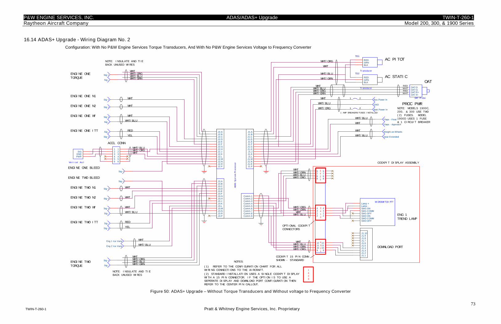
P&W ENGINE SERVICES, INC. ADAS/ADAS+ Upgrade TWIN-T-260-1Raytheon Aircraft Company Model 200, 300, & 1900 Series
73TWIN-T-260-1 Pratt & Whitney Engine Services, Inc. Proprietary
16.14 ADAS+ Upgrade - Wiring Diagram No. 2
Configuration: With No P&W Engine Services Torque Transducers, And With No P&W Engine Services Voltage to Frequency Converter
Transducer
TD1
RED
BLKGRN
Transducer
TD2
RED
BLKGRN
Sig +
Sig -
Sig +
Sig -
Sig +
Sig +
Sig +
Sig -
Sig +
Sig +
Sig +
Sig -
Sig +
Weight-on-Wheels
Gear Extended
Flaps - Approach
Flaps - Final
J1.1J1.2J1.3J1.4J1.5J1.6J1.7J1.8J1.9J1.10
Sig +
1 2
1 2
MICROSWITCH PTTLamp +Lamp -SW1-ONSW1-COMMSW1-OFFSW2-ONSW2-COMMSW2-OFF
68
75
9
68
75
9
12
34
12
34
101112
101112
Vertical Accl
SIG
PWRGND
123456
123456
Eng 1 Ice Vane
Eng 2 Ice Vane
ADAS
System
Processor
J1.AJ1.BJ1.C
J1.L
J1.DJ1.EJ1.FJ1.GJ1.HJ1.JJ1.K
J1.MJ1.NJ1.RJ1.P
Comm.1Comm.2Comm.3Comm.4Comm.5Comm.6Comm.7Comm.8Comm.9
J3.AJ3.BJ3.CJ3.DJ3.EJ3.FJ3.GJ3.HJ3.JJ3.KJ3.LJ3.MJ3.NJ3.RJ3.P
J2.AJ2.BJ2.CJ2.DJ2.EJ2.FJ2.GJ2.HJ2.JJ2.KJ2.LJ2.MJ2.NJ2.RJ2.P
Bus Power In
GND
Batt Power In
OAT Probe
OAT-GWHT
OAT-R+RED
OAT-DRED
OAT R-WHT
ENGINE ONE Wf
ENGINE ONE N2
ENGINE ONE N1
ENGINE TWOTORQUE
DOWNLOAD PORT
ENG 1TREND LAMP
ENGINE ONETORQUE
ENGINE TWO ITT
AC STATIC
AC PITOT
ENGINE TWO N2
ENGINE TWO N1
ENGINE ONE ITT
WHT/ORG
WHT
WHT/GRNWHT/BLUWHT/ORG
ENGINE TWO Wf
RED
WHT/BLU
WHT
WHT/BLUWHT/ORG
WHT
WHT/BLUWHT/GRN
WHT/BLU
WHT
WHT
WHT
WHT
WHT
WHT
YEL
WHT/GRN
WHT/BLU
WHT
WHT/ORG
YEL
RED
WHT/BLU
WHT
WHT
WHT/BLU
WHTWHT/GRNWHT/ORG
WHT/BLU
WHTWHT/GRN
WHT/ORG
COCKPIT 15 PIN CONN
SHOWN - STANDARD
1 AMP BREAKERS/FUSES INSTALLED
ENGINE ONE BLEED
WHT/ORGWHT/GRN
WHTWHT/BLU
WHT/BLU
1
4
2
3
4
3
2
1
3
4
1
2
WHT/BLU
WHT/ORG
WHT
1
4
2
3
ENGINE TWO BLEED
OAT
COCKPIT DISPLAY ASSEMBLY
OPTIONAL COCKPIT
CONNECTORS
PROC PWR
ACCL CONN
NOTE: INSULATE AND TIE
BACK UNUSED WIRES
WHT/BLU
WHT
Sig +
Sig -
NOTE: INSULATE AND TIE
BACK UNUSED WIRES
NOTE: MODELS 1900C,
200, & 300 USE TWO
(2) FUSES. MODEL
1900D USES 1 FUSE
& 1 CIRCUIT BREAKER
WHTWHT/BLU
(2) STANDARD INSTALLATION USES A SINGLE COCKPIT DISPLAY
WITH A 15 PIN CONNECTOR. IF THE OPTION IS TO USE A
SEPERATE DISPLAY AND DOWNLOAD PORT CONFIGURATION THEN
REFER TO THE CENTER PIN CALLOUT.
WHT/GRNWHT/ORG
(1) REFER TO THE CONFIGURATION CHART FOR ALL
WIRING CONNECTIONS TO THE AIRCRAFT.
NOTES:
Sig +
Sig -
Figure 50: ADAS+ Upgrade – Without Torque Transducers and Without voltage to Frequency Converter
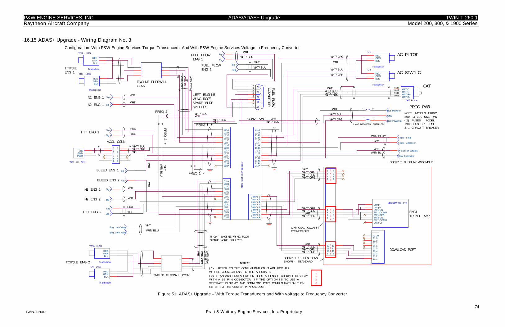
P&W ENGINE SERVICES, INC. ADAS/ADAS+ Upgrade TWIN-T-260-1Raytheon Aircraft Company Model 200, 300, & 1900 Series
74TWIN-T-260-1 Pratt & Whitney Engine Services, Inc. Proprietary
16.15 ADAS+ Upgrade - Wiring Diagram No. 3
Configuration: With P&W Engine Services Torque Transducers, And With P&W Engine Services Voltage to Frequency Converter
NOTE: MODELS 1900C,
200, & 300 USE TWO
(2) FUSES. MODEL
1900D USES 1 FUSE
& 1 CIRCUIT BREAKER
PROC PWR
FREQ 1 +
Sig +
Transducer
TD3 - HIGH
RED
BLKGRN
Sig +
Sig -
Transducer
TD4 - LOW
RED
BLKGRN
Transducer
TD6 - LOW
RED
BLKGRN
Sig +
Sig -
.
.
.
.
.
.
.
.
.
.
Transducer
TD5 - HIGH
RED
BLKGRN
J1.1J1.2J1.3J1.4J1.5J1.6J1.7J1.8J1.9J1.10
Weight-on-Wheels
Gear Extended
Flaps - Approach
Flaps - Final
68
75
9
68
75
9
12
34
12
34
101112
101112
1 2
Sig +
Sig +
Sig +
Sig -
Sig +
Sig -
Transducer
TD2
RED
BLKGRN
Transducer
TD1
RED
BLKGRN
594837261
1 2
Sig +
Sig +
123456
123456
ADAS
System
Processor
J1.AJ1.BJ1.C
J1.L
J1.DJ1.EJ1.FJ1.GJ1.HJ1.JJ1.K
J1.MJ1.NJ1.RJ1.P
Comm.1Comm.2Comm.3Comm.4Comm.5Comm.6Comm.7Comm.8Comm.9
J3.AJ3.BJ3.CJ3.DJ3.EJ3.FJ3.GJ3.HJ3.JJ3.KJ3.LJ3.MJ3.NJ3.RJ3.P
J2.AJ2.BJ2.CJ2.DJ2.EJ2.FJ2.GJ2.HJ2.JJ2.KJ2.LJ2.MJ2.NJ2.RJ2.P
.
.
.
.
.
.
.
.
.
.
Sig +
Vertical Accl
SIG
PWRGND
ENG1TREND LAMP
TORQUEENG 1
1
4
2
3
AC PITOT
N2 ENG 2
ITT ENG 1
FUEL FLOWENG 1
N2 ENG 1
N1 ENG 1
TORQUE ENG 2
DOWNLOAD PORT
WHT/GRN
WHT/BLU
WHT/ORG
ENGINE FIREWALL CONN
RIGHT ENGINE WING ROOT
SPARE WIRE SPLICES
ITT ENG 2
ENGINE FIREWALLCONN
AC STATIC
YEL
RED
WHT/ORG
WHT/BLU
WHT/GRN
WHT
WHT/GRN
WHT/BLU
WHT
WHT/ORG
WHT/BLU
WHT
WHT
WHT
WHT/ORG
FREQ 1 -
WHT/GRNWHT/ORG
WHT/BLU
WHTWHT/GRN
FUEL
FLOW
CONVERTER
FUEL FLOWENG 2
WHTN1 ENG 2
WHT
WHT
WHT
WHT/BLU
WHT/BLUWHT
WHT
WHT
(2) STANDARD INSTALLATION USES A SINGLE COCKPIT DISPLAY
WITH A 15 PIN CONNECTOR. IF THE OPTION IS TO USE A
SEPERATE DISPLAY AND DOWNLOAD PORT CONFIGURATION THEN
REFER TO THE CENTER PIN CALLOUT.
COCKPIT 15 PIN CONN
SHOWN - STANDARDNOTES:
(1) REFER TO THE CONFIGURATION CHART FOR ALL
WIRING CONNECTIONS TO THE AIRCRAFT.
WHT/BLU
WHT/BLU
WHT
WHT
Bus Power In
GND
Batt Power In
OAT Probe
OAT-GWHT
OAT-R+RED
OAT-DRED
OAT R-WHT
RED
YEL
MICROSWITCH PTTLamp +Lamp -SW1-ONSW1-COMMSW1-OFFSW2-ONSW2-COMMSW2-OFF
Eng 1 Ice Vane
Eng 2 Ice Vane
WHT
WHT/BLU
WHT/BLUWHT
LEFT ENGINEWING ROOTSPARE WIRESPLICES
FREQ 2 -
WHT/BLU
FREQ
2+
WHT/BLUWHT
WHT/GRNWHT/ORG
WHT/BLUWHT
WHT/GRN
WHTWHT/BLU
1 AMP BREAKERS INSTALLED
BLEED ENG 1
WHT/ORG
WHT/ORG
WHT
4
3
2
1
3
4
1
2
WHT/BLU
COCKPIT DISPLAY ASSEMBLY
OPTIONAL COCKPIT
CONNECTORS
1
4
2
3BLEED ENG 2
OAT
WHT/BLU
WHT
CONV PWR
WHT/BLU
WHT
ACCL CONN
WHT
WHT/ORG
Figure 51: ADAS+ Upgrade – With Torque Transducers and With voltage to Frequency Converter
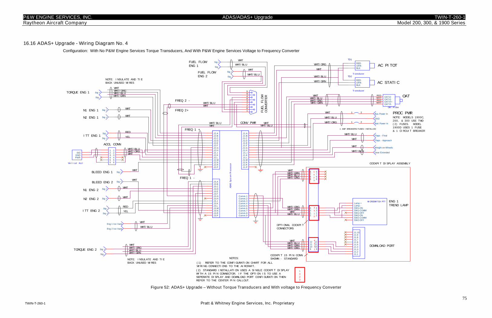
P&W ENGINE SERVICES, INC. ADAS/ADAS+ Upgrade TWIN-T-260-1Raytheon Aircraft Company Model 200, 300, & 1900 Series
75TWIN-T-260-1 Pratt & Whitney Engine Services, Inc. Proprietary
16.16 ADAS+ Upgrade - Wiring Diagram No. 4
Configuration: With No P&W Engine Services Torque Transducers, And With P&W Engine Services Voltage to Frequency Converter
TORQUE ENG 1
FREQ 1 +
FREQ 1 -
N1 ENG 1
N2 ENG 1
DOWNLOAD PORT
ITT ENG 1
AC PITOT
N2 ENG 2
N1 ENG 2
ITT ENG 2
AC STATIC
WHT/BLUWHT/ORG
RED
WHT
WHT
YEL
WHT
WHT
WHT
WHT/ORG
YEL
RED
WHT/BLU
WHT
WHT/GRN
WHT
WHT
WHT
WHT/BLU
WHT/BLUWHT/GRN
COCKPIT 15 PIN CONN
SHOWN - STANDARD
WHT/BLU
WHT/ORG
WHTWHT/GRN
WHT/ORG
WHT/GRNWHT/ORG
WHT/BLU
WHT/BLUWHT
WHT/GRN
WHTWHT/BLU
1 AMP BREAKERS/FUSES INSTALLED
BLEED ENG 1
WHT/ORG
PROC PWR
WHT/ORG
WHT
1
4
2
3
4
3
2
1
WHT/BLU
OAT
COCKPIT DISPLAY ASSEMBLY
OPTIONAL COCKPIT
CONNECTORS
BLEED ENG 2
(2) STANDARD INSTALLATION USES A SINGLE COCKPIT DISPLAY
WITH A 15 PIN CONNECTOR. IF THE OPTION IS TO USE A
SEPERATE DISPLAY AND DOWNLOAD PORT CONFIGURATION THEN
REFER TO THE CENTER PIN CALLOUT.
NOTES:
WHT/GRN
ACCL CONN
WHT/BLU
TORQUE ENG 2
(1) REFER TO THE CONFIGURATION CHART FOR ALL
WIRING CONNECTIONS TO THE AIRCRAFT.
3
4
1
2
1
4
2
3
NOTE: INSULATE AND TIE
BACK UNUSED WIRES
Sig +
Sig +
Sig -
Transducer
TD1
RED
BLKGRN
Transducer
TD2
RED
BLKGRN
Flaps - Approach
Flaps - FinalSig +
Sig -
Sig +
Sig +
Sig +
Sig +
Weight-on-Wheels
Gear Extended
1 2
J1.1J1.2J1.3J1.4J1.5J1.6J1.7J1.8J1.9J1.10
MICROSWITCH PTTLamp +Lamp -SW1-ONSW1-COMMSW1-OFFSW2-ONSW2-COMMSW2-OFF
Vertical Accl
SIG
PWRGND
123456
123456
1 2
Sig +
Sig -
Sig +
Sig -
ADAS
System
Processor
J1.AJ1.BJ1.C
J1.L
J1.DJ1.EJ1.FJ1.GJ1.HJ1.JJ1.K
J1.MJ1.NJ1.RJ1.P
Comm.1Comm.2Comm.3Comm.4Comm.5Comm.6Comm.7Comm.8Comm.9
J3.AJ3.BJ3.CJ3.DJ3.EJ3.FJ3.GJ3.HJ3.JJ3.KJ3.LJ3.MJ3.NJ3.RJ3.P
J2.AJ2.BJ2.CJ2.DJ2.EJ2.FJ2.GJ2.HJ2.JJ2.KJ2.LJ2.MJ2.NJ2.RJ2.P
68
75
9
68
75
9
12
34
12
34
101112
101112
Sig +
Sig -
Sig +
594837261
Sig +
Sig -
WHTWHT/ORG
OAT Probe
OAT-GWHT
OAT-R+RED
OAT-DRED
OAT R-WHT
FREQ 2 -
Bus Power In
GND
Batt Power In
NOTE: MODELS 1900C,
200, & 300 USE TWO
(2) FUSES. MODEL
1900D USES 1 FUSE
& 1 CIRCUIT BREAKER
Eng 1 Ice Vane
Eng 2 Ice Vane
WHT
WHT/BLU
WHT
WHT/ORGWHT/BLU
WHT/GRN
FUEL FLOWENG 1 WHT/BLU
WHT/BLU
WHT
WHT
FUEL FLOWENG 2
FUEL
FLOW
CONVERTER
WHT/BLU
WHT/BLU
WHTWHT
WHT
WHT/BLU
WHT
WHT
ENG 1TREND LAMP
NOTE: INSULATE AND TIE
BACK UNUSED WIRES
CONV PWR
FREQ 2+
Figure 52: ADAS+ Upgrade – Without Torque Transducers and With voltage to Frequency Converter


![11 S.. · 11 s.. aq.. s.. 11.2 s.. aq.. 11.2.1 s 37 aq.. [nm] ... 44.22 155 210 260 155 210 260 155 210 260 155 210 260 47.32 155 210 260 155 210 260 155 210 260 155 210 260](https://img.pdfslide.net/doc/110x75/5b189dcc7f8b9a19258bfc6f/11-s-11-s-aq-s-112-s-aq-1121-s-37-aq-nm-4422-155-210.jpg)