Embed Size (px)
Citation preview
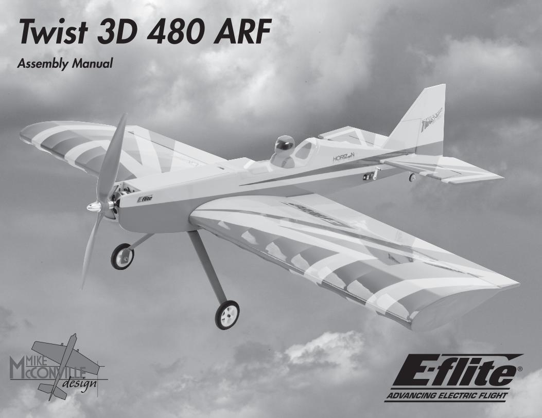
Twist 3D 480 ARFAssembly Manual

2 E-flite Twist 3D 480 ARF Assembly Manual
NoticeAll instructions, warranties and other collateral
documents are subject to change at the sole discretion of Horizon Hobby, Inc. For up-to-date
product literature, visit http://www.horizonhobby.com and click on the support tab for this product.
Meaning of Special LanguageThe following terms are used throughout the product literature to indicate various levels of potential harm
when operating this product:NOTICE: Procedures, which if not properly followed,
create a possibility of physical property damage AND a little or no possibility of injury.
CAUTION: Procedures, which if not properly followed, create the probability of physical property damage
AND a possibility of serious injury.WARNING: Procedures, which if not properly followed, create the probability of property damage, collateral
damage, and serious injury OR create a high probability of superficial injury.
This is a sophisticated hobby product and NOT a toy. It must be operated with caution and common
sense and requires some basic mechanical ability. Failure to operate this Product in a safe
and responsible manner could result in injury or damage to the product or other property. This
product is not intended for use by children without direct adult supervision. Do not attempt disassembly,
use with incompatible components or augment product in any way without the approval of Horizon
Hobby, Inc. This manual contains instructions for safety, operation and maintenance. It is essential to read and follow all the instructions and warnings in the manual, prior to assembly, setup or use, in order to operate correctly and avoid damage or
serious injury.
Warnings
Read and follow all instructions and safety precautions before use. Improper use can result in fire, serious injury and damage to property.
Age Recommendation: Not for Children under 14 years.
This is not a toy.
COMpONENTS
Use only with compatible components. Should any compatibility questions exist, please refer to the product instructions, the component instructions or contact Horizon Hobby, Inc.
FLIGhT
Fly only in open areas to ensure safety. It is recommended flying be done at AMA (Academy of Model Aeronautics) approved flying sites. Consult local laws and ordinances before choosing a location to fly your aircraft.
pROpELLER
Keep loose items that can get entangled in the propeller away from the prop, including loose clothing or other objects such as pencils and screwdrivers. Especially keep your hands away from the propeller as injury can occur.
BATTERIES
Notes on Lithium polymer Batteries
Always follow the manufacturer’s instructions when using and disposing of any batteries. Mishandling of Li-Po batteries can result in fire causing serious injury and damage.
SMALL pARTS
This kit includes small parts and should not be left unattended near children as choking and serious injury could result.
SAFETy pRECAUTIONS
• Checkallcontrolsurfacespriortoeachtakeoff.
• Donotflyyourmodelnearspectators,parkingareas or any other area that could result in injury to people or damage of property.
• Donotflyduringadverseweatherconditions.Poor visibility and/or strong winds can cause disorientation and loss of control of your aircraft.
• Donottakechances.Ifatanytimeduringflightyouobserve any erratic or abnormal operation, land immediately and do not resume flight until the cause of the problem has been ascertained and corrected. Safety can never be taken lightly.
• Donotflynearpowerlines.
WARNING: Read the ENTIRE instruction manual to become familiar with the features of the product before operating. Failure to operate the
product correctly can result in damage to the product, personal property and cause serious injury.
3E-flite Twist 3D 480 ARF Assembly Manual
Table of ContentsNotice ................................................................... 2Meaning of Special Language ................................. 2Warnings .............................................................. 2Introduction ........................................................... 3Important Information Regarding
Warranty Information ..................................... 3Specifications ......................................................... 3Using the Manual ................................................... 3Contents of Kit/Parts Layout .................................... 4Covering Colors ..................................................... 4Recommended Radio Equipment ............................. 4High-Power Setup (Recommended) .......................... 4Sport-Power Setup (Optional) ................................. 4Required Tools and Adhesives ................................. 4Optional Accessories .............................................. 4Aileron Servo Installation ........................................ 5Hinging the Ailerons .............................................. 6Aileron Linkage Installation ..................................... 7Landing Gear Installation ........................................ 8Motor Installation ................................................... 9Wing Installation .................................................. 11Stabilizer Installation ............................................ 12Vertical Fin Installation .......................................... 14Rudder and Elevator Installation ............................ 15Rudder and Elevator Servo Installation ................... 17Canopy Installation .............................................. 19Center of Gravity ................................................. 20Control Throws..................................................... 21Preflight ............................................................... 21Range Test Your Radio .......................................... 22Flying Your Model ................................................ 22Daily Flight Checks ............................................... 23Limited Warranty ................................................. 23Warranty Services ................................................ 24Compliance Information for the European Union .... 25Academy of Model Aeronautics
National Model Aircraft Safety Code ............ 25Building and Flying Notes ..................................... 27
IntroductionThank you for purchasing the E-flite® Twist 3D 480 ARF RC sport model. Your handsome new airplane is a modern design application of form and function to provide a great flying model that builds quickly. A blast to fly with an electric 450- or 480-class power system, it is perfectly matched for the E-flite Park 450- to 480-size brushless outrunner motors (EFLM1400, EFLM1505) that are world renown for great power and reliability. Contemporary all-wood construction makes the Twist 3D 480 very strong, plus its high-contrast genuine UltraCote® covering will keep looking beautiful for a long time. For convenience, the large top and bottom hatches offer virtually unlimited access to vital components. To get the best performance the Twist 3D 480 has to offer, optional wheel pants (EFL2607) and a pilot figure (PKZ5105) are available as shown on the box.
The lightweight Twist 3D 480 is outstanding at low-speed flight and offers friendly handling even while performing extreme maneuvers. Please be sure to read through this manual carefully so that you can successfully enjoy all the benefits this great electric powered ARF model has to offer.
Important Information Regarding Warranty Information
Please read our Warranty and Liability Limitations in the back of this manual before building this product. If you as the Purchaser or user are not prepared to accept the liability associated with the use of this Product, you are advised to return this Product immediately in new and unused condition to the place of purchase.
SpecificationsWingspan: 35.0 in (890mm)Wing Area: 404 sq in (16.0 sq dm)Fuselage Length: 34.5 in (880mm)Weight w/ Battery: 25.9–29.6 oz (735–840 g)Weight w/o Battery: 20.8–23.3 oz (590–660 g)
Using the ManualThis manual is divided into sections to help make assembly easier to understand and to provide breaks between each major section. In addition, check boxes have been placed next to each step to keep track of its completion. Steps with a single circle () are performed once, while steps with two or more circles () indicate the step will require repeating, such as for a right or left wing panel, two servos, etc.Remember to take your time and follow the directions.
4 E-flite Twist 3D 480 ARF Assembly Manual
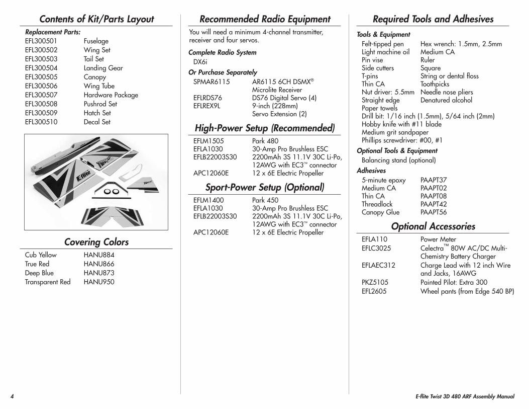
Contents of Kit/parts LayoutReplacement parts:EFL300501 FuselageEFL300502 Wing SetEFL300503 Tail SetEFL300504 Landing GearEFL300505 CanopyEFL300506 Wing TubeEFL300507 Hardware PackageEFL300508 Pushrod SetEFL300509 Hatch SetEFL300510 Decal Set
Covering ColorsCub Yellow HANU884True Red HANU866Deep Blue HANU873Transparent Red HANU950
Recommended Radio EquipmentYou will need a minimum 4-channel transmitter, receiver and four servos.
Complete Radio SystemDX6i
Or purchase SeparatelySPMAR6115 AR6115 6CH DSMX®
Microlite ReceiverEFLRDS76 DS76 Digital Servo (4)EFLREX9L 9-inch (228mm)
Servo Extension (2)
high-power Setup (Recommended)EFLM1505 Park 480EFLA1030 30-Amp Pro Brushless ESCEFLB22003S30 2200mAh 3S 11.1V 30C Li-Po,
12AWG with EC3™ connectorAPC12060E 12 x 6E Electric Propeller
Sport-power Setup (Optional)EFLM1400 Park 450EFLA1030 30-Amp Pro Brushless ESCEFLB22003S30 2200mAh 3S 11.1V 30C Li-Po,
12AWG with EC3™ connectorAPC12060E 12 x 6E Electric Propeller
Required Tools and AdhesivesTools & Equipment
Felt-tipped pen Hex wrench: 1.5mm, 2.5mmLight machine oil Medium CAPin vise RulerSide cutters SquareT-pins String or dental flossThin CA ToothpicksNut driver: 5.5mm Needle nose pliersStraight edge Denatured alcoholPaper towelsDrill bit: 1/16 inch (1.5mm), 5/64 inch (2mm)Hobby knife with #11 bladeMedium grit sandpaperPhillips screwdriver: #00, #1
Optional Tools & EquipmentBalancing stand (optional)
Adhesives5-minute epoxy PAAPT37Medium CA PAAPT02Thin CA PAAPT08Threadlock PAAPT42Canopy Glue PAAPT56
Optional AccessoriesEFLA110 Power MeterEFLC3025 Celectra™ 80W AC/DC Multi-
Chemistry Battery Charger EFLAEC312 Charge Lead with 12 inch Wire
and Jacks, 16AWGPKZ5105 Painted Pilot: Extra 300EFL2605 Wheel pants (from Edge 540 BP)
5E-flite Twist 3D 480 ARF Assembly Manual
During the course of building your model, we suggest you use a soft base for the building surface.
Such things as a foam stand, large piece of bedding foam or a thick bath towel will work well and help protect the model from damage during
assembly. This is not shown in the instructions to provide the greatest detail in the photos.
When referencing directions (up, down, left, right top and bottom), these directions are in relationship to the pilot sitting in the cockpit
of the aircraft, unless noted otherwise.
Before starting the assembly of your model, we recommend preparing your radio system for
installation. This includes charging the transmitter and receiver batteries, as well as centering the trims and sticks on your transmitter. If using a computer radio, make sure to reset a model memory and name it for this particular model. We also recommend binding the transmitter and receiver at this time, following the instructions provided with your radio system.
We highly recommend re-binding the radio system once all the control throws are set. This will
keep the servos from moving to their endpoints until the transmitter and receiver connect.
Aileron Servo InstallationRequired parts
Wing panel (right and left)Servo with hardware (2)
Required Tools and AdhesivesThin CA Phillips screwdriver: #1
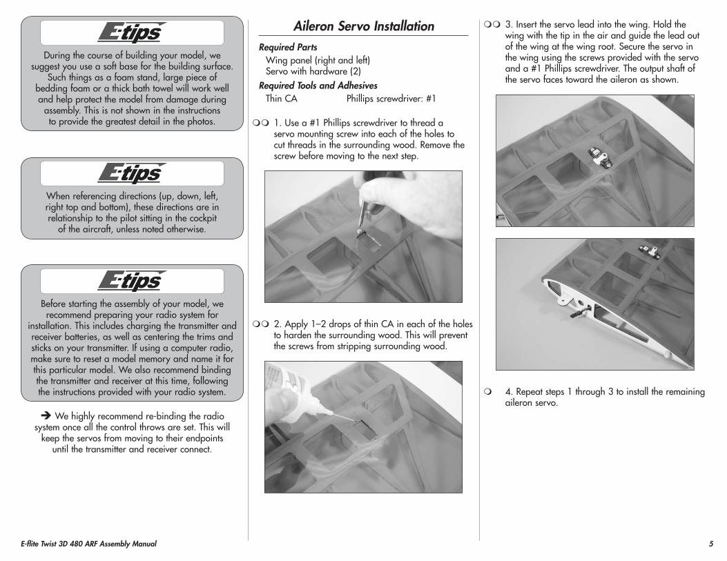
1. Use a #1 Phillips screwdriver to thread a servo mounting screw into each of the holes to cut threads in the surrounding wood. Remove the screw before moving to the next step.
2. Apply 1–2 drops of thin CA in each of the holes to harden the surrounding wood. This will prevent the screws from stripping surrounding wood.
3. Insert the servo lead into the wing. Hold the wing with the tip in the air and guide the lead out of the wing at the wing root. Secure the servo in the wing using the screws provided with the servo and a #1 Phillips screwdriver. The output shaft of the servo faces toward the aileron as shown.
4. Repeat steps 1 through 3 to install the remaining aileron servo.
6 E-flite Twist 3D 480 ARF Assembly Manual
hinging the AileronsRequired parts
Wing panel (right and left)Aileron (right and leftCA hinge (8)
Required Tools and AdhesivesThin CA T-pinsPin vise Drill bit: 1/16-inch (1.5mm)
1. Use a pin vise and 1/16-inch (1.5mm) drill bit to drill a hole in the center of each hinge slot in the aileron and wing to create a tunnel for the CA to wick into. This will allow the CA to penetrate the hinge, creating a better bond between the hinge and surrounding wood.
2. Place a T-pin in the center of each of the five hinges. This will center the hinges equally in the aileron and wing when they are installed.
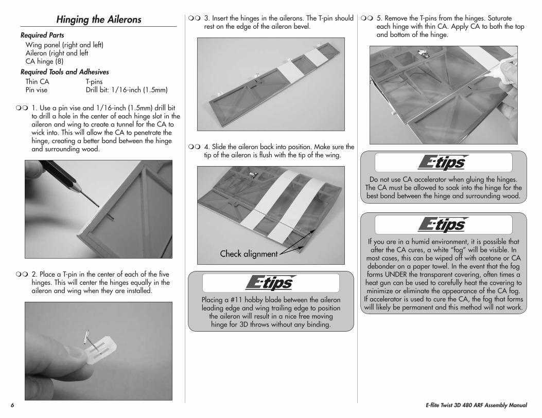
3. Insert the hinges in the ailerons. The T-pin should rest on the edge of the aileron bevel.
4. Slide the aileron back into position. Make sure the tip of the aileron is flush with the tip of the wing.
Placing a #11 hobby blade between the aileron leading edge and wing trailing edge to position
the aileron will result in a nice free moving hinge for 3D throws without any binding.
5. Remove the T-pins from the hinges. Saturate each hinge with thin CA. Apply CA to both the top and bottom of the hinge.
Do not use CA accelerator when gluing the hinges. The CA must be allowed to soak into the hinge for the best bond between the hinge and surrounding wood.
If you are in a humid environment, it is possible that after the CA cures, a white “fog” will be visible. In
most cases, this can be wiped off with acetone or CA debonder on a paper towel. In the event that the fog forms UNDER the transparent covering, often times a heat gun can be used to carefully heat the covering to minimize or eliminate the appearance of the CA fog.
If accelerator is used to cure the CA, the fog that forms will likely be permanent and this method will not work.
7E-flite Twist 3D 480 ARF Assembly Manual
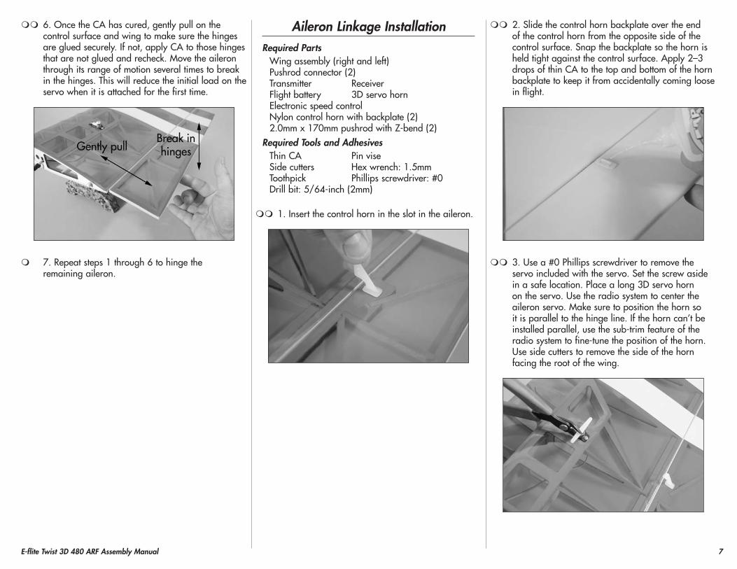
6. Once the CA has cured, gently pull on the control surface and wing to make sure the hinges are glued securely. If not, apply CA to those hinges that are not glued and recheck. Move the aileron through its range of motion several times to break in the hinges. This will reduce the initial load on the servo when it is attached for the first time.
7. Repeat steps 1 through 6 to hinge the remaining aileron.
Aileron Linkage InstallationRequired parts
Wing assembly (right and left)Pushrod connector (2)Transmitter ReceiverFlight battery 3D servo hornElectronic speed controlNylon control horn with backplate (2)2.0mm x 170mm pushrod with Z-bend (2)
Required Tools and AdhesivesThin CA Pin viseSide cutters Hex wrench: 1.5mmToothpick Phillips screwdriver: #0Drill bit: 5/64-inch (2mm)
1. Insert the control horn in the slot in the aileron.
2. Slide the control horn backplate over the end of the control horn from the opposite side of the control surface. Snap the backplate so the horn is held tight against the control surface. Apply 2–3 drops of thin CA to the top and bottom of the horn backplate to keep it from accidentally coming loose in flight.
3. Use a #0 Phillips screwdriver to remove the servo included with the servo. Set the screw aside in a safe location. Place a long 3D servo horn on the servo. Use the radio system to center the aileron servo. Make sure to position the horn so it is parallel to the hinge line. If the horn can’t be installed parallel, use the sub-trim feature of the radio system to fine-tune the position of the horn. Use side cutters to remove the side of the horn facing the root of the wing.
8 E-flite Twist 3D 480 ARF Assembly Manual
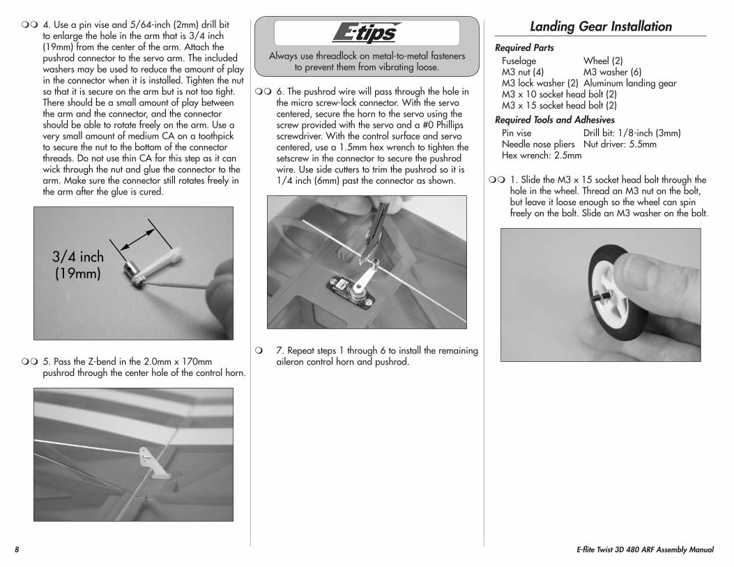
4. Use a pin vise and 5/64-inch (2mm) drill bit to enlarge the hole in the arm that is 3/4 inch (19mm) from the center of the arm. Attach the pushrod connector to the servo arm. The included washers may be used to reduce the amount of play in the connector when it is installed. Tighten the nut so that it is secure on the arm but is not too tight. There should be a small amount of play between the arm and the connector, and the connector should be able to rotate freely on the arm. Use a very small amount of medium CA on a toothpick to secure the nut to the bottom of the connector threads. Do not use thin CA for this step as it can wick through the nut and glue the connector to the arm. Make sure the connector still rotates freely in the arm after the glue is cured.
5. Pass the Z-bend in the 2.0mm x 170mm pushrod through the center hole of the control horn.
Always use threadlock on metal-to-metal fasteners to prevent them from vibrating loose.
6. The pushrod wire will pass through the hole in the micro screw-lock connector. With the servo centered, secure the horn to the servo using the screw provided with the servo and a #0 Phillips screwdriver. With the control surface and servo centered, use a 1.5mm hex wrench to tighten the setscrew in the connector to secure the pushrod wire. Use side cutters to trim the pushrod so it is 1/4 inch (6mm) past the connector as shown.
7. Repeat steps 1 through 6 to install the remaining aileron control horn and pushrod.
Landing Gear InstallationRequired parts
Fuselage Wheel (2)M3 nut (4) M3 washer (6)M3 lock washer (2) Aluminum landing gearM3 x 10 socket head bolt (2)M3 x 15 socket head bolt (2)
Required Tools and AdhesivesPin vise Drill bit: 1/8-inch (3mm)Needle nose pliers Nut driver: 5.5mmHex wrench: 2.5mm
1. Slide the M3 x 15 socket head bolt through the hole in the wheel. Thread an M3 nut on the bolt, but leave it loose enough so the wheel can spin freely on the bolt. Slide an M3 washer on the bolt.
9E-flite Twist 3D 480 ARF Assembly Manual
Always use threadlock on metal-to-metal fasteners to prevent them from vibrating loose.
2. Insert the bolt in the landing gear. Place an M3 washer, then an M3 nut on the bolt. Use needle nose pliers and a 5.5mm nut driver to tighten the nut, securing the wheel to the landing gear. Make sure the wheel still rotates freely once the nuts are fully tightened.
3. Repeat steps 1 and 2 to attach the remaining wheel to the landing gear.
4. Attach the landing gear to the fuselage using two M3 x 10 socket head bolts, two M3 washers and two M3 lock washers. Slide the lock washer on the bolt, then the washer, before securing the gear. Use a 2.5mm hex wrench to tighten the bolts.
Motor InstallationRequired parts
Fuselage assembly Flight batterySpeed control Motor with hardwareReceiver Hook and loop tapeTransmitter Hook and loop strapM3 washer (4) M3 blind nut (4)M3 lock washer (4) M3 x 10 socket head bolt (4)
Required Tools and AdhesivesThreadlock ScissorsHex wrench: 2.5mm
1. Remove the hatch from the fuselage by lifting it up at the rear. The rear is held in position using a magnet and the front has tabs that lock the hatch to the fuselage. Set the hatch aside in a safe location until later.
Always use threadlock on metal-to-metal fasteners.
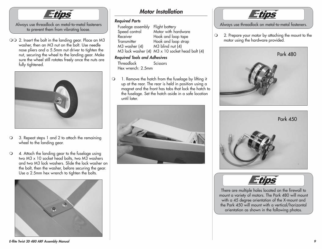
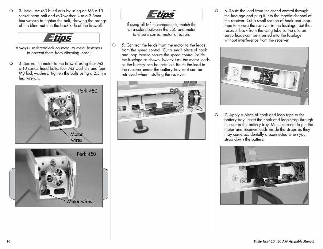
2. Prepare your motor by attaching the mount to the motor using the hardware provided.
There are multiple holes located on the firewall to mount a variety of motors. The Park 480 will mount
with a 45 degree orientation of the X-mount and the Park 450 will mount with a vertical/horizontal
orientation as shown in the following photos.
10 E-flite Twist 3D 480 ARF Assembly Manual
3. Install the M3 blind nuts by using an M3 x 10 socket head bolt and M3 washer. Use a 2.5mm hex wrench to tighten the bolt, drawing the prongs of the blind nut into the back side of the firewall.
Always use threadlock on metal-to-metal fasteners to prevent them from vibrating loose.
4. Secure the motor to the firewall using four M3 x 10 socket head bolts, four M3 washers and four M3 lock washers. Tighten the bolts using a 2.5mm hex wrench.
If using all E-flite components, match the wire colors between the ESC and motor
to ensure correct motor direction.
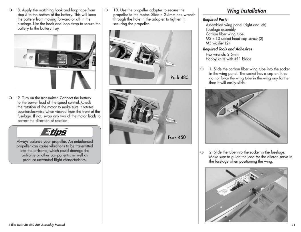
5. Connect the leads from the motor to the leads from the speed control. Cut a small piece of hook and loop tape to secure the speed control inside the fuselage as shown. Neatly tuck the motor leads so the battery can be installed. Route the lead to the receiver under the battery tray so it can be retrieved when installing the receiver.
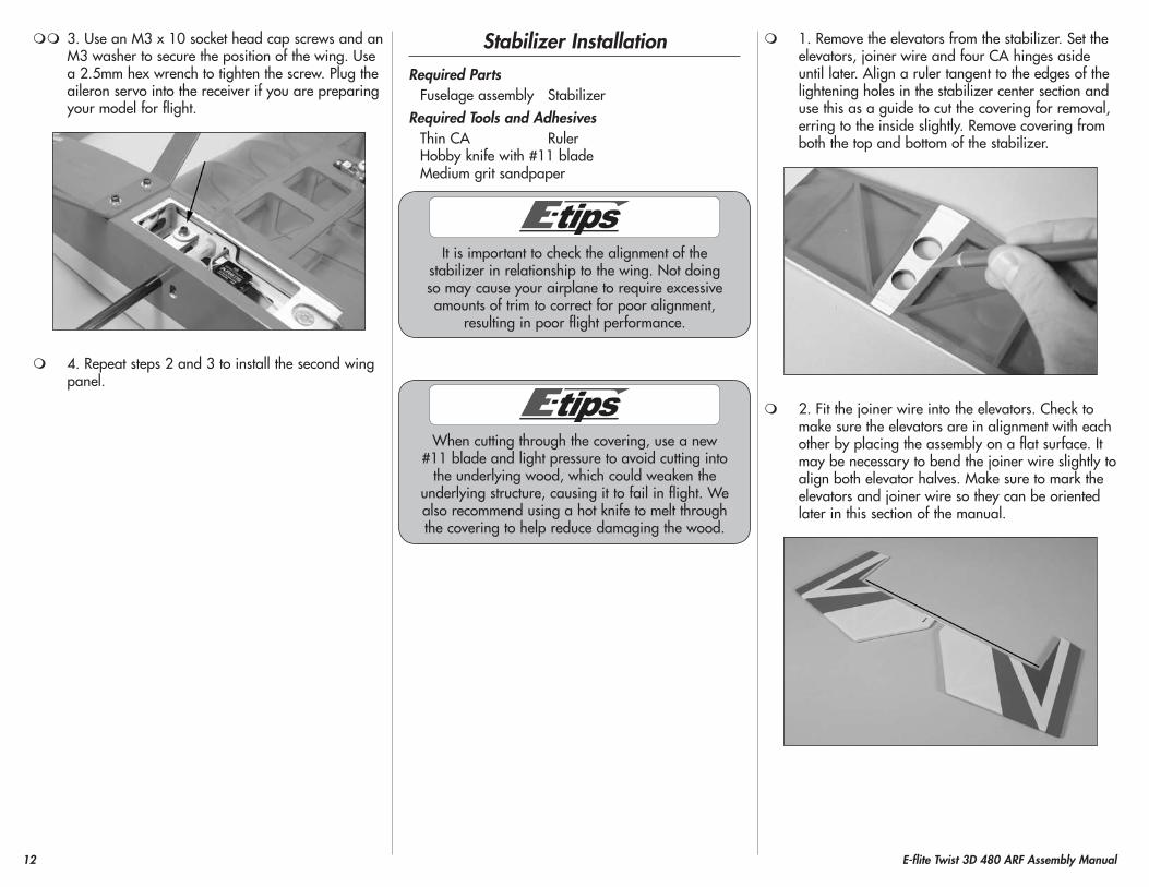
6. Route the lead from the speed control through the fuselage and plug it into the throttle channel of the receiver. Cut a small section of hook and loop tape to secure the receiver in the fuselage. Set the receiver back from the wing tube so the aileron servo leads can be inserted into the fuselage without interference from the receiver.
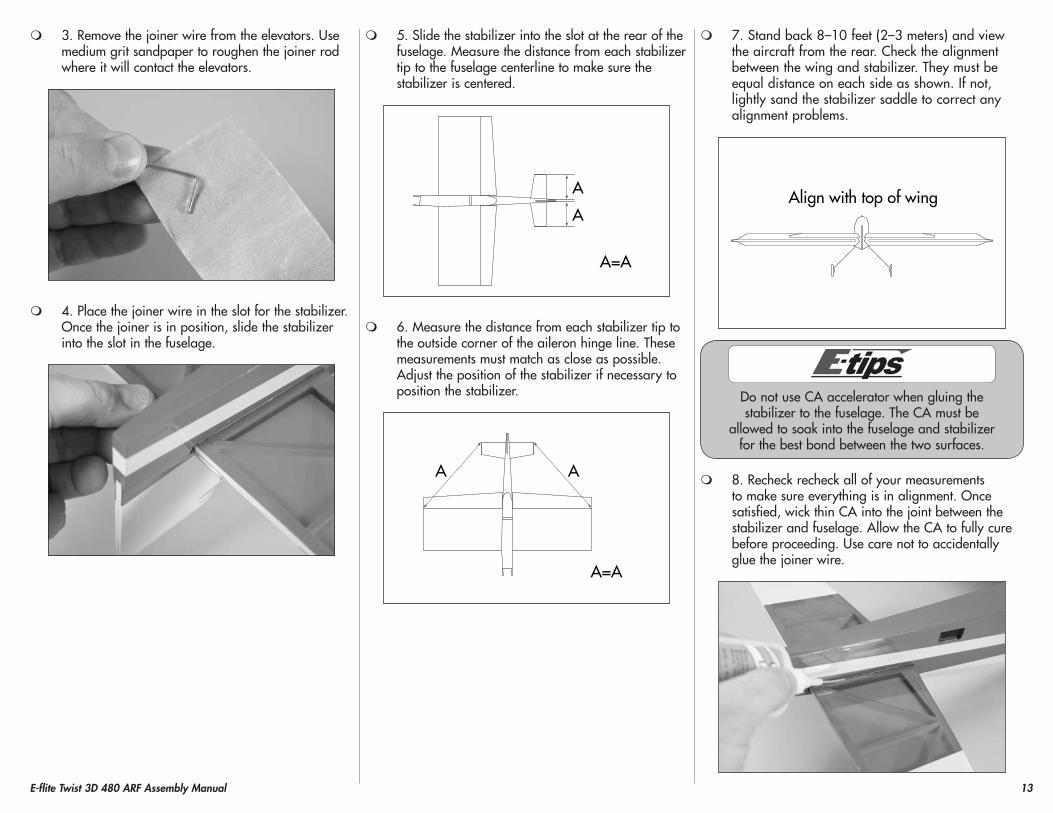
7. Apply a piece of hook and loop tape to the battery tray. Insert the hook and loop strap through the slot in the battery tray. Make sure not to get the motor and receiver leads inside the straps as they may come accidentally disconnected when you strap down the battery.
11E-flite Twist 3D 480 ARF Assembly Manual
8. Apply the matching hook and loop tape from step 5 to the bottom of the battery. This will keep the battery from moving forward or aft in the fuselage. Use the hook and loop strap to secure the battery to the battery tray.
9. Turn on the transmitter. Connect the battery to the power lead of the speed control. Check the rotation of the motor to make sure it rotates counterclockwise when viewed from the front of the fuselage. If not, swap any two of the motor leads to correct the direction of rotation.
Always balance your propeller. An unbalanced propeller can cause vibrations to be transmitted
into the airframe, which could damage the airframe or other components, as well as produce unwanted flight characteristics.
10. Use the propeller adapter to secure the propeller to the motor. Slide a 2.5mm hex wrench through the hole in the adapter to tighten it, securing the propeller.
Wing InstallationRequired parts
Assembled wing panel (right and left)Fuselage assemblyCarbon fiber wing tubeM3 x 10 socket head cap screw (2)M3 washer (2)
Required Tools and AdhesivesHex wrench: 2.5mmHobby knife with #11 blade
1. Slide the carbon fiber wing tube into the socket in the wing panel. The socket has a cap on it, so do not force the wing tube in the wing any farther than it will easily slide.
2. Slide the tube into the socket in the fuselage. Make sure to guide the lead for the aileron servo in the fuselage when positioning the wing.
12 E-flite Twist 3D 480 ARF Assembly Manual
3. Use an M3 x 10 socket head cap screws and an M3 washer to secure the position of the wing. Use a 2.5mm hex wrench to tighten the screw. Plug the aileron servo into the receiver if you are preparing your model for flight.
4. Repeat steps 2 and 3 to install the second wing panel.
Stabilizer InstallationRequired parts
Fuselage assembly StabilizerRequired Tools and Adhesives
Thin CA RulerHobby knife with #11 bladeMedium grit sandpaper
It is important to check the alignment of the stabilizer in relationship to the wing. Not doing so may cause your airplane to require excessive amounts of trim to correct for poor alignment,
resulting in poor flight performance.
When cutting through the covering, use a new #11 blade and light pressure to avoid cutting into
the underlying wood, which could weaken the underlying structure, causing it to fail in flight. We also recommend using a hot knife to melt through the covering to help reduce damaging the wood.
1. Remove the elevators from the stabilizer. Set the elevators, joiner wire and four CA hinges aside until later. Align a ruler tangent to the edges of the lightening holes in the stabilizer center section and use this as a guide to cut the covering for removal, erring to the inside slightly. Remove covering from both the top and bottom of the stabilizer.
2. Fit the joiner wire into the elevators. Check to make sure the elevators are in alignment with each other by placing the assembly on a flat surface. It may be necessary to bend the joiner wire slightly to align both elevator halves. Make sure to mark the elevators and joiner wire so they can be oriented later in this section of the manual.
13E-flite Twist 3D 480 ARF Assembly Manual
3. Remove the joiner wire from the elevators. Use medium grit sandpaper to roughen the joiner rod where it will contact the elevators.
4. Place the joiner wire in the slot for the stabilizer. Once the joiner is in position, slide the stabilizer into the slot in the fuselage.
5. Slide the stabilizer into the slot at the rear of the fuselage. Measure the distance from each stabilizer tip to the fuselage centerline to make sure the stabilizer is centered.
A
A
A=A
6. Measure the distance from each stabilizer tip to the outside corner of the aileron hinge line. These measurements must match as close as possible. Adjust the position of the stabilizer if necessary to position the stabilizer.
A=A
AA
7. Stand back 8–10 feet (2–3 meters) and view the aircraft from the rear. Check the alignment between the wing and stabilizer. They must be equal distance on each side as shown. If not, lightly sand the stabilizer saddle to correct any alignment problems.
Align with top of wing
Do not use CA accelerator when gluing the stabilizer to the fuselage. The CA must be
allowed to soak into the fuselage and stabilizer for the best bond between the two surfaces.
8. Recheck recheck all of your measurements to make sure everything is in alignment. Once satisfied, wick thin CA into the joint between the stabilizer and fuselage. Allow the CA to fully cure before proceeding. Use care not to accidentally glue the joiner wire.
14 E-flite Twist 3D 480 ARF Assembly Manual
Vertical Fin InstallationRequired parts
Fuselage assembly FinRequired Tools and Adhesives
Felt-tipped pen Thin CASquare Hobby knife with #11 bladeStraight edge
The wing can be removed at this time to allow the fuselage to be easier to manage during the
remainder of the assembly of your model.
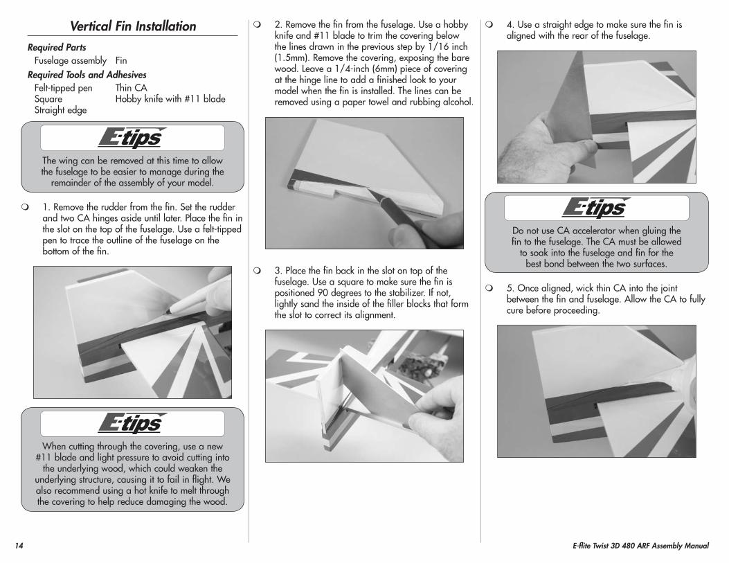
1. Remove the rudder from the fin. Set the rudder and two CA hinges aside until later. Place the fin in the slot on the top of the fuselage. Use a felt-tipped pen to trace the outline of the fuselage on the bottom of the fin.
When cutting through the covering, use a new #11 blade and light pressure to avoid cutting into
the underlying wood, which could weaken the underlying structure, causing it to fail in flight. We also recommend using a hot knife to melt through the covering to help reduce damaging the wood.
2. Remove the fin from the fuselage. Use a hobby knife and #11 blade to trim the covering below the lines drawn in the previous step by 1/16 inch (1.5mm). Remove the covering, exposing the bare wood. Leave a 1/4-inch (6mm) piece of covering at the hinge line to add a finished look to your model when the fin is installed. The lines can be removed using a paper towel and rubbing alcohol.
3. Place the fin back in the slot on top of the fuselage. Use a square to make sure the fin is positioned 90 degrees to the stabilizer. If not, lightly sand the inside of the filler blocks that form the slot to correct its alignment.
4. Use a straight edge to make sure the fin is aligned with the rear of the fuselage.
Do not use CA accelerator when gluing the fin to the fuselage. The CA must be allowed
to soak into the fuselage and fin for the best bond between the two surfaces.
5. Once aligned, wick thin CA into the joint between the fin and fuselage. Allow the CA to fully cure before proceeding.
15E-flite Twist 3D 480 ARF Assembly Manual
Rudder and Elevator InstallationRequired parts
Fuselage assembly RudderElevators CA hinge (6)Elevator joiner wire Tail wheel assembly
Required Tools and AdhesivesThin CA T-pinsPin vise Drill bit: 1/16-inch (1.5mm)5-minute epoxy Hobby knife with #11 bladeToothpicks Light machine oil
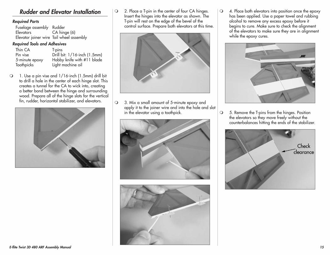
1. Use a pin vise and 1/16-inch (1.5mm) drill bit to drill a hole in the center of each hinge slot. This creates a tunnel for the CA to wick into, creating a better bond between the hinge and surrounding wood. Prepare all of the hinge slots for the vertical fin, rudder, horizontal stabilizer, and elevators.
2. Place a T-pin in the center of four CA hinges. Insert the hinges into the elevator as shown. The T-pin will rest on the edge of the bevel of the control surface. Prepare both elevators at this time.
3. Mix a small amount of 5-minute epoxy and apply it to the joiner wire and into the hole and slot in the elevator using a toothpick.
4. Place both elevators into position once the epoxy has been applied. Use a paper towel and rubbing alcohol to remove any excess epoxy before it begins to cure. Make sure to check the alignment of the elevators to make sure they are in alignment while the epoxy cures.
5. Remove the T-pins from the hinges. Position the elevators so they move freely without the counterbalances hitting the ends of the stabilizer.
16 E-flite Twist 3D 480 ARF Assembly Manual
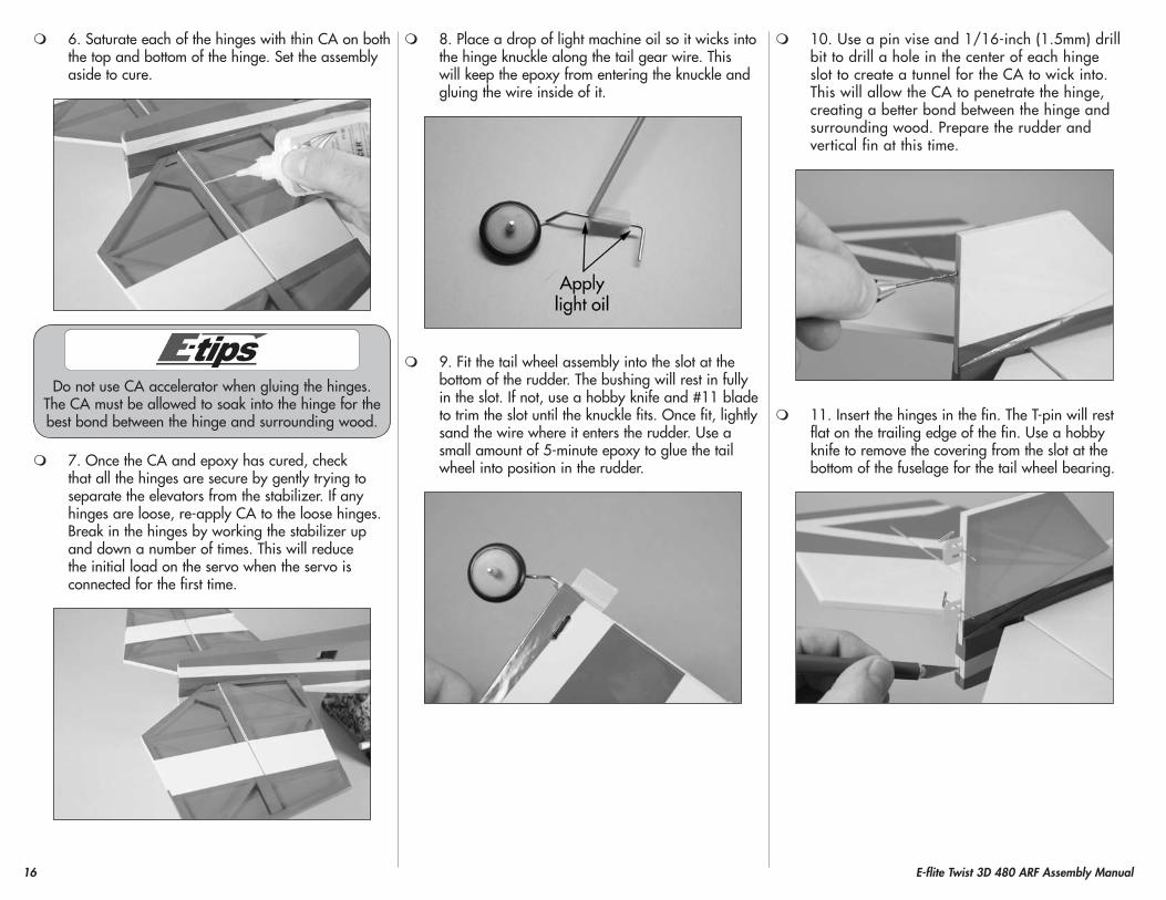
6. Saturate each of the hinges with thin CA on both the top and bottom of the hinge. Set the assembly aside to cure.
Do not use CA accelerator when gluing the hinges. The CA must be allowed to soak into the hinge for the best bond between the hinge and surrounding wood.
7. Once the CA and epoxy has cured, check that all the hinges are secure by gently trying to separate the elevators from the stabilizer. If any hinges are loose, re-apply CA to the loose hinges. Break in the hinges by working the stabilizer up and down a number of times. This will reduce the initial load on the servo when the servo is connected for the first time.
8. Place a drop of light machine oil so it wicks into the hinge knuckle along the tail gear wire. This will keep the epoxy from entering the knuckle and gluing the wire inside of it.
9. Fit the tail wheel assembly into the slot at the bottom of the rudder. The bushing will rest in fully in the slot. If not, use a hobby knife and #11 blade to trim the slot until the knuckle fits. Once fit, lightly sand the wire where it enters the rudder. Use a small amount of 5-minute epoxy to glue the tail wheel into position in the rudder.
10. Use a pin vise and 1/16-inch (1.5mm) drill bit to drill a hole in the center of each hinge slot to create a tunnel for the CA to wick into. This will allow the CA to penetrate the hinge, creating a better bond between the hinge and surrounding wood. Prepare the rudder and vertical fin at this time.
11. Insert the hinges in the fin. The T-pin will rest flat on the trailing edge of the fin. Use a hobby knife to remove the covering from the slot at the bottom of the fuselage for the tail wheel bearing.
17E-flite Twist 3D 480 ARF Assembly Manual
12. Slide the rudder into position, guiding the tab on the tail wheel knuckle into the slot at the bottom of the rudder.
13. Check to make sure the counterbalance can move freely without hitting the top of the fin. Remove the t-pins from the hinges and apply thin CA to each of the hinges. Make sure to fully saturate both sides of the hinges.
Do not use CA accelerator when gluing the hinges. The CA must be allowed to soak into the hinge for the best bond between the hinge and surrounding wood.
14. Once the CA has cured, gently pull on the control surfaces and fin to make sure the hinges are glued securely. If not, apply CA to those hinges that are not glued and recheck.
15. Move the rudder through its range of motion a number of times to break in the hinges. This will reduce the initial load on the servo when the servo is connected for the first time.
Rudder and Elevator Servo InstallationRequired parts
Fuselage Servo with hardware (2)Flight battery Pushrod connector (2)Transmitter9-inch (228mm) servo extension (2)Nylon control horn with backplate (2)2.0mm x 170mm pushrod with Z-bend (2)
Required Tools and AdhesivesMedium CA Thin CASide cutters String or dental flossHex wrench: 1.5mmPin vise Phillips screwdriver: #0, #1Drill bit: 5/64-inch (2mm)
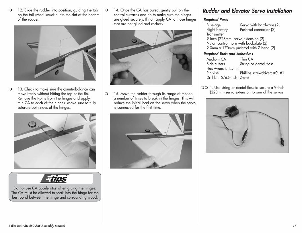
1. Use string or dental floss to secure a 9-inch (228mm) servo extension to one of the servos.
18 E-flite Twist 3D 480 ARF Assembly Manual
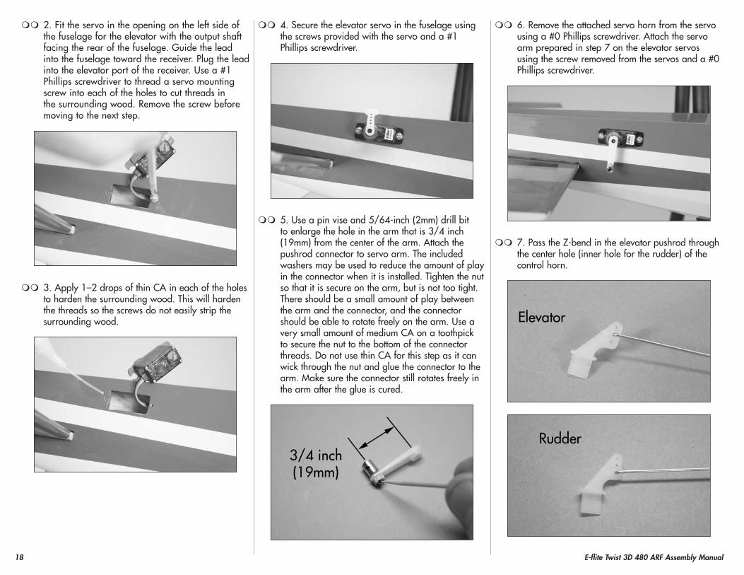
2. Fit the servo in the opening on the left side of the fuselage for the elevator with the output shaft facing the rear of the fuselage. Guide the lead into the fuselage toward the receiver. Plug the lead into the elevator port of the receiver. Use a #1 Phillips screwdriver to thread a servo mounting screw into each of the holes to cut threads in the surrounding wood. Remove the screw before moving to the next step.
3. Apply 1–2 drops of thin CA in each of the holes to harden the surrounding wood. This will harden the threads so the screws do not easily strip the surrounding wood.
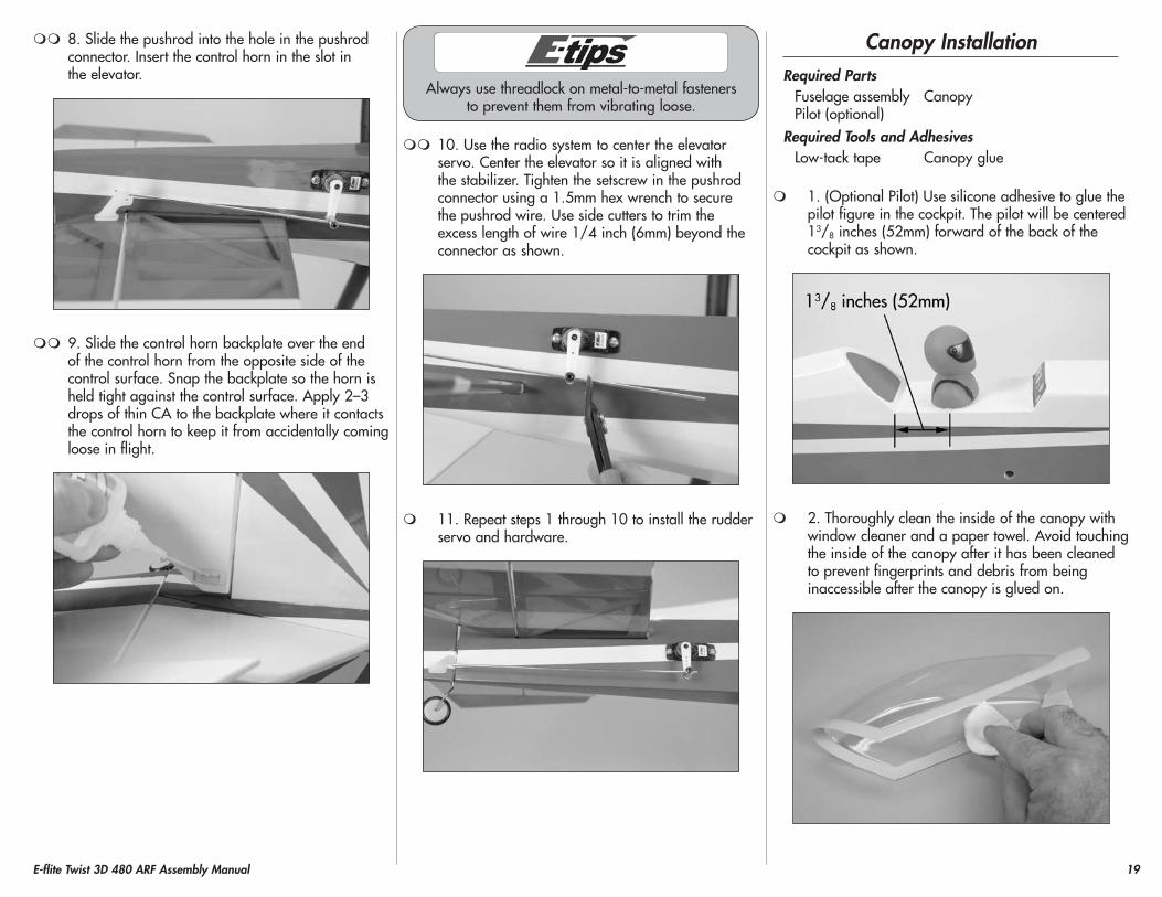
4. Secure the elevator servo in the fuselage using the screws provided with the servo and a #1 Phillips screwdriver.
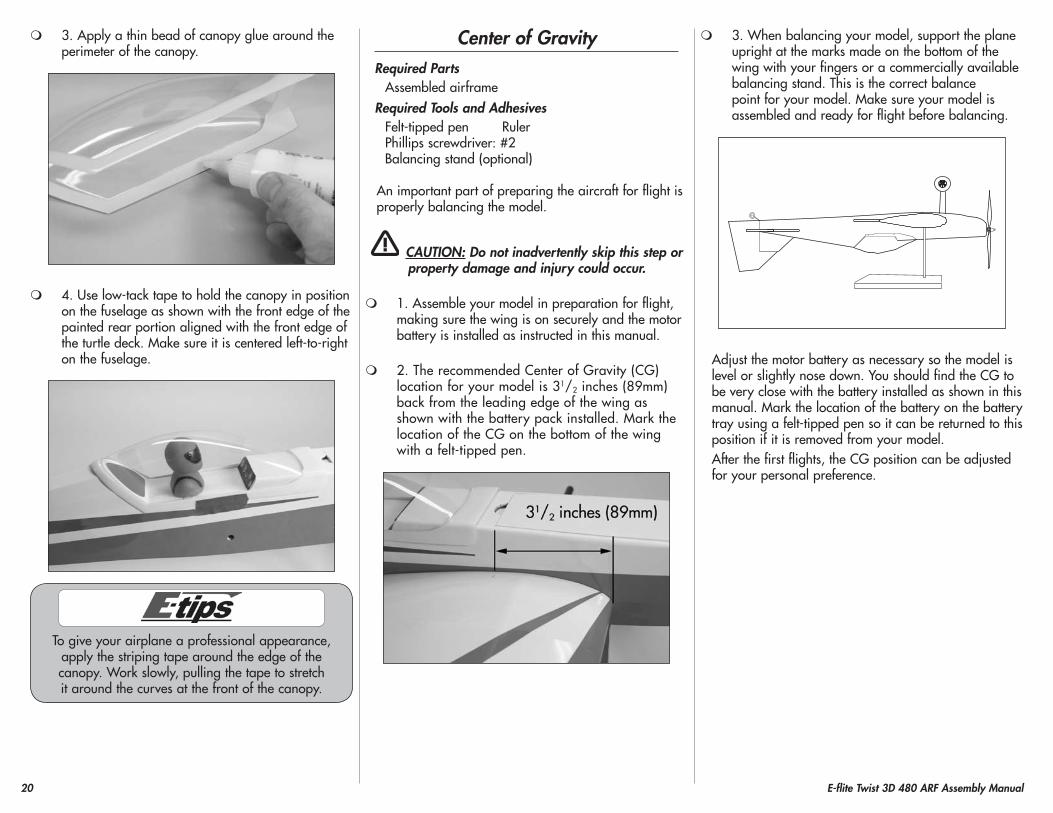
5. Use a pin vise and 5/64-inch (2mm) drill bit to enlarge the hole in the arm that is 3/4 inch (19mm) from the center of the arm. Attach the pushrod connector to servo arm. The included washers may be used to reduce the amount of play in the connector when it is installed. Tighten the nut so that it is secure on the arm, but is not too tight. There should be a small amount of play between the arm and the connector, and the connector should be able to rotate freely on the arm. Use a very small amount of medium CA on a toothpick to secure the nut to the bottom of the connector threads. Do not use thin CA for this step as it can wick through the nut and glue the connector to the arm. Make sure the connector still rotates freely in the arm after the glue is cured.
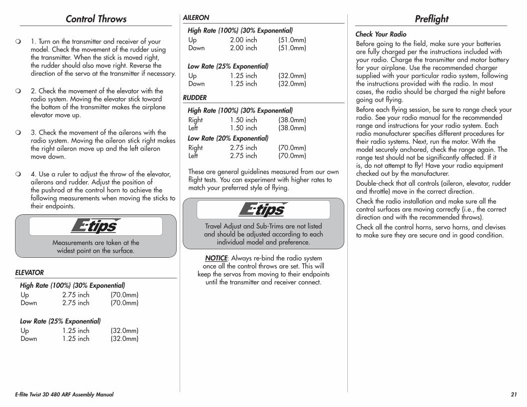
6. Remove the attached servo horn from the servo using a #0 Phillips screwdriver. Attach the servo arm prepared in step 7 on the elevator servos using the screw removed from the servos and a #0 Phillips screwdriver.
7. Pass the Z-bend in the elevator pushrod through the center hole (inner hole for the rudder) of the control horn.
19E-flite Twist 3D 480 ARF Assembly Manual
8. Slide the pushrod into the hole in the pushrod connector. Insert the control horn in the slot in the elevator.
9. Slide the control horn backplate over the end of the control horn from the opposite side of the control surface. Snap the backplate so the horn is held tight against the control surface. Apply 2–3 drops of thin CA to the backplate where it contacts the control horn to keep it from accidentally coming loose in flight.
Always use threadlock on metal-to-metal fasteners to prevent them from vibrating loose.
10. Use the radio system to center the elevator servo. Center the elevator so it is aligned with the stabilizer. Tighten the setscrew in the pushrod connector using a 1.5mm hex wrench to secure the pushrod wire. Use side cutters to trim the excess length of wire 1/4 inch (6mm) beyond the connector as shown.
11. Repeat steps 1 through 10 to install the rudder servo and hardware.
Canopy InstallationRequired parts
Fuselage assembly CanopyPilot (optional)
Required Tools and AdhesivesLow-tack tape Canopy glue
1. (Optional Pilot) Use silicone adhesive to glue the pilot figure in the cockpit. The pilot will be centered 13/8 inches (52mm) forward of the back of the cockpit as shown.
2. Thoroughly clean the inside of the canopy with window cleaner and a paper towel. Avoid touching the inside of the canopy after it has been cleaned to prevent fingerprints and debris from being inaccessible after the canopy is glued on.
20 E-flite Twist 3D 480 ARF Assembly Manual
3. Apply a thin bead of canopy glue around the perimeter of the canopy.
4. Use low-tack tape to hold the canopy in position on the fuselage as shown with the front edge of the painted rear portion aligned with the front edge of the turtle deck. Make sure it is centered left-to-right on the fuselage.
To give your airplane a professional appearance, apply the striping tape around the edge of the canopy. Work slowly, pulling the tape to stretch it around the curves at the front of the canopy.
Center of GravityRequired parts
Assembled airframeRequired Tools and Adhesives
Felt-tipped pen RulerPhillips screwdriver: #2Balancing stand (optional)
An important part of preparing the aircraft for flight is properly balancing the model.
CAUTION: Do not inadvertently skip this step or property damage and injury could occur.
1. Assemble your model in preparation for flight, making sure the wing is on securely and the motor battery is installed as instructed in this manual.
2. The recommended Center of Gravity (CG) location for your model is 31/2 inches (89mm) back from the leading edge of the wing as shown with the battery pack installed. Mark the location of the CG on the bottom of the wing with a felt-tipped pen.
3. When balancing your model, support the plane upright at the marks made on the bottom of the wing with your fingers or a commercially available balancing stand. This is the correct balance point for your model. Make sure your model is assembled and ready for flight before balancing.
Adjust the motor battery as necessary so the model is level or slightly nose down. You should find the CG to be very close with the battery installed as shown in this manual. Mark the location of the battery on the battery tray using a felt-tipped pen so it can be returned to this position if it is removed from your model.After the first flights, the CG position can be adjusted for your personal preference.
21E-flite Twist 3D 480 ARF Assembly Manual
Control Throws
1. Turn on the transmitter and receiver of your model. Check the movement of the rudder using the transmitter. When the stick is moved right, the rudder should also move right. Reverse the direction of the servo at the transmitter if necessary.
2. Check the movement of the elevator with the radio system. Moving the elevator stick toward the bottom of the transmitter makes the airplane elevator move up.
3. Check the movement of the ailerons with the radio system. Moving the aileron stick right makes the right aileron move up and the left aileron move down.
4. Use a ruler to adjust the throw of the elevator, ailerons and rudder. Adjust the position of the pushrod at the control horn to achieve the following measurements when moving the sticks to their endpoints.
Measurements are taken at the widest point on the surface.
ELEVATOR
high Rate (100%) (30% Exponential)Up 2.75 inch (70.0mm)Down 2.75 inch (70.0mm)
Low Rate (25% Exponential)Up 1.25 inch (32.0mm)Down 1.25 inch (32.0mm)
AILERON
high Rate (100%) (30% Exponential)Up 2.00 inch (51.0mm)Down 2.00 inch (51.0mm)
Low Rate (25% Exponential)Up 1.25 inch (32.0mm)Down 1.25 inch (32.0mm)
RUDDER
high Rate (100%) (30% Exponential)Right 1.50 inch (38.0mm)Left 1.50 inch (38.0mm)Low Rate (20% Exponential)Right 2.75 inch (70.0mm)Left 2.75 inch (70.0mm)
These are general guidelines measured from our own flight tests. You can experiment with higher rates to match your preferred style of flying.
Travel Adjust and Sub-Trims are not listed and should be adjusted according to each
individual model and preference.
NOTICE: Always re-bind the radio system once all the control throws are set. This will
keep the servos from moving to their endpoints until the transmitter and receiver connect.
preflightCheck your RadioBefore going to the field, make sure your batteries are fully charged per the instructions included with your radio. Charge the transmitter and motor battery for your airplane. Use the recommended charger supplied with your particular radio system, following the instructions provided with the radio. In most cases, the radio should be charged the night before going out flying.Before each flying session, be sure to range check your radio. See your radio manual for the recommended range and instructions for your radio system. Each radio manufacturer specifies different procedures for their radio systems. Next, run the motor. With the model securely anchored, check the range again. The range test should not be significantly affected. If it is, do not attempt to fly! Have your radio equipment checked out by the manufacturer.Double-check that all controls (aileron, elevator, rudder and throttle) move in the correct direction.Check the radio installation and make sure all the control surfaces are moving correctly (i.e., the correct direction and with the recommended throws).Check all the control horns, servo horns, and clevises to make sure they are secure and in good condition.
22 E-flite Twist 3D 480 ARF Assembly Manual
Range Test your RadioBefore each flying session, and especially with a new model, it is important to perform a range check. It is helpful to have another person available to assist during the range check. If you are using a Spektrum™ transmitter, please refer to your transmitter’s manual for detailed instructions on the range check process.
1. With the model resting on the ground, stand 30 paces (approximately 90 feet) away from the model.
2. Face the model with the transmitter in your normal flying position. Be sure the throttle is in the full down position and plug the flight battery into the speed control.
3. As you move the controls, watch to be sure the airplane’s motor and controls operate smoothly. You should have total control of the model at 30 paces (90 feet).
4. If control issues exist, call the appropriate Horizon Product Support office (see addresses listed in the Warranty Services section of this manual) or go to horizonhobby.com to find a local Spektrum distributor in your country for service when using a Spektrum radio system.
Flying your ModelThe Twist 3D 480 shares many of the same flying qualities of its larger brethren; however, due to its small size, very low weight and light wing loading, it is a very capable 3D performer that can be unleashed practically anywhere!Before arriving to the field, verify that the airplane balances within the range specified here in the manual, as well as control throws and direction have been set. Once you have arrived to the field, install your battery and reconfirm that everything is still in good order. Taxi out to the runway and line up with the centerline, facing into the wind. You’ll find that even though the landing gear is a conventional arrangement, due to the long tail moment, taxiing is very easy. Once aligned with the runway, set the throttle trim that the propeller is spinning at a very low RPM; this will be your flight idle and will be very important during 3D flight. Smoothly increase the throttle and use small rudder corrections to keep the airplane tracking straight down the runway. It will lift off very quickly due to the low wing loading and high power. Climb to a comfortable altitude and trim the airplane to fly hands off at around half throttle. Limit your use of higher throttle for maneuvering. Due to the large control surface area, flutter is possible at higher airspeeds, and this can lead to a crash if you’re not careful.You’ll find that the airplane is quite capable of a full battery of 3D maneuvers; torque rolls, harrier rolls, waterfalls, you name it and the Twist 3D 480 will deliver with gusto. After your initial flights, you can adjust the CG to suite your flying style. You’ll find that this little dynamo’s flight envelope is limited only by your imagination!
You’ll want to setup for landing before your battery gets too low (although the airplane is very easy to fly dead stick!). Begin by entering the pattern downwind at about half throttle. Once abeam of your touchdown point, slowly reduce power and allow the airplane to descend. You need not fly a base and final leg, simply make a descending 180-degree pattern to line up with the runway. Remember to use the throttle to control altitude and elevator to control airspeed. Once you have the runway made, slowly come off the throttle completely and allow the airplane to settle in for a nice, three point landing. Rollout will be short, because you won’t be moving very quickly at touchdown.Congratulations! You have just flown your Twist 3D 480 ARF! We hope you enjoy this model as much as we do. Now what are you waiting for? Get back out there and do it again!
23E-flite Twist 3D 480 ARF Assembly Manual
Daily Flight Checks
1. Check the battery voltage of the transmitter battery. Do not fly below the manufacturer’s recommended voltage. To do so may cause your aircraft to crash.
When you check these batteries, ensure you have the polarities correct on your expanded scale voltmeter.
2. Check all hardware (linkages, screws, nuts, and bolts) prior to each day’s flight. Be sure that binding does not occur and that all parts are properly secured.
3. Ensure all surfaces are moving in the proper manner.
4. Perform a ground range check before each day’s flying session.
5. Prior to starting your aircraft, turn off your transmitter, then turn it back on. Do this each time you start your aircraft. If any critical switches are on without your knowledge, the transmitter alarm will sound a warning.
6. Check that all trim levers are in the proper location.
7. All servo pigtails and switch harness plugs should be secured in the receiver. Make sure the switch harness moves freely in both directions.
Limited Warranty
WhAT ThIS WARRANTy COVERSHorizon Hobby, Inc. (“Horizon”) warrants to the original purchaser that the product purchased (the “Product”) will be free from defects in materials and workmanship at the date of purchase.
WhAT IS NOT COVEREDThis warranty is not transferable and does not cover (i) cosmetic damage, (ii) damage due to acts of God, accident, misuse, abuse, negligence, commercial use, or due to improper use, installation, operation or maintenance, (iii) modification of or to any part of the Product, (iv) attempted service by anyone other than a Horizon Hobby authorized service center, or (v) Products not purchased from an authorized Horizon dealer. OTHER THAN THE EXPRESS WARRANTY ABOVE, HORIZON MAKES NO OTHER WARRANTY OR REPRESENTATION, AND HEREBY DISCLAIMS ANY AND ALL IMPLIED WARRANTIES, INCLUDING, WITHOUT LIMITATION, THE IMPLIED WARRANTIES OF NON-INFRINGEMENT, MERCHANTABILITY AND FITNESS FOR A PARTICULAR PURPOSE. THE PURCHASER ACKNOWLEDGES THAT THEY ALONE HAVE DETERMINED THAT THE PRODUCT WILL SUITABLY MEET THE REQUIREMENTS OF THE PURCHASER’S INTENDED USE.
pURChASER’S REMEDyHorizon’s sole obligation and purchaser’s sole and exclusive remedy shall be that Horizon will, at its option, either (i) service, or (ii) replace, any Product determined by Horizon to be defective. Horizon reserves the right to inspect any and all Product(s) involved in a warranty claim. Service or replacement decisions are at the sole discretion of Horizon. Proof of purchase is required for all warranty claims. SERVICE OR REPLACEMENT AS PROVIDED UNDER THIS WARRANTY IS THE PURCHASER’S SOLE AND EXCLUSIVE REMEDY.
LIMITATION OF LIABILITyHORIZON SHALL NOT BE LIABLE FOR SPECIAL, INDIRECT, INCIDENTAL OR CONSEQUENTIAL DAMAGES, LOSS OF PROFITS OR PRODUCTION OR COMMERCIAL LOSS IN ANY WAY, REGARDLESS OF WHETHER SUCH CLAIM IS BASED IN CONTRACT, WARRANTY, TORT, NEGLIGENCE, STRICT LIABILITY OR ANY OTHER THEORY OF LIABILITY, EVEN IF HORIZON HAS BEEN ADVISED OF THE POSSIBILITY OF SUCH DAMAGES. Further, in no event shall the liability of Horizon exceed the individual price of the Product on which liability is asserted. As Horizon has no control over use, setup, final assembly, modification or misuse, no liability shall be assumed nor accepted for any resulting damage or injury. By the act of use, setup or assembly, the user accepts all resulting liability. If you as the purchaser or user are not prepared to accept the liability associated with the use of the Product, purchaser is advised to return the Product immediately in new and unused condition to the place of purchase.
LAWThese terms are governed by Illinois law (without regard to conflict of law principals). This warranty gives you specific legal rights, and you may also have other rights which vary from state to state. Horizon reserves the right to change or modify this warranty at any time without notice.
24 E-flite Twist 3D 480 ARF Assembly Manual
Warranty Services
QUESTIONS, ASSISTANCE, AND SERVICESYour local hobby store and/or place of purchase cannot provide warranty support or service. Once assembly, setup or use of the Product has been started, you must contact Horizon directly. This will enable Horizon to better answer your questions and service you in the event that you may need any assistance. For questions or assistance, please direct your email to [email protected], or call 877.504.0233 toll free to speak to a Product Support representative. You may also find information on our website at www.horizonhobby.com.
INSpECTION OR SERVICESIf this Product needs to be inspected or serviced, please use the Horizon Online Service Request submission process found on our website or call Horizon to obtain a Return Merchandise Authorization (RMA) number. Pack the Product securely using a shipping carton. Please note that original boxes may be included, but are not designed to withstand the rigors of shipping without additional protection. Ship via a carrier that provides tracking and insurance for lost or damaged parcels, as Horizon is not responsible for merchandise until it arrives and is accepted at our facility. An Online Service Request is available at http://www.horizonhobby.com under the Support tab. If you do not have internet access, please contact Horizon Product Support to obtain a RMA number along with instructions for submitting your product for service. When calling Horizon, you will be asked to provide your complete name, street address, email address and phone number where you can be reached during business hours. When sending product into Horizon, please include your RMA number, a list of the included items, and a brief summary of the problem. A copy of your original sales receipt must be included for warranty consideration. Be sure your name, address, and RMA number are clearly written on the outside of the shipping carton.Notice: Do not ship Lipo batteries to horizon. If you have any issue with a Lipo battery, please contact the appropriate horizon product Support office.
WARRANTy REQUIREMENTS For Warranty consideration, you must include your original sales receipt verifying the proof-of-purchase date. Provided warranty conditions have been met, your Product will be serviced or replaced free of charge. Service or replacement decisions are at the sole discretion of Horizon.
NON-WARRANTy SERVICEShould your service not be covered by warranty service will be completed and payment will be required without notification or estimate of the expense unless the expense exceeds 50% of the retail purchase cost. By submitting the item for service you are agreeing to payment of the service without notification. Service estimates are available upon request. You must include this request with your item submitted for service. Non-warranty service estimates will be billed a minimum of ½ hour of labor. In addition you will be billed for return freight. Horizon accepts money orders and cashiers checks, as well as Visa, MasterCard, American Express, and Discover cards. By submitting any item to Horizon for service, you are agreeing to Horizon’s Terms and Conditions found on our website http://www.horizonhobby.com/Service/Request/.
UNITED STATES(Electronics and engines)Horizon Service Center
4105 Fieldstone RdChampaign, Illinois
61822 [email protected]
877-504-0233Online Repair Request visit:
www.horizonhobby.com/service
(All other products)Horizon Product Support
4105 Fieldstone RdChampaign, Illinois
61822 [email protected]
877-504-0233
UNITED KINGDOMHorizon Hobby LimitedUnits 1-4 Ployters Rd
Staple TyeHarlow, EssexCM18 7NS
United [email protected]+44 (0) 1279 641 097
GERMANyHorizon Technischer Service
Christian-Junge-Straße 125337 Elmshorn, [email protected]+49(0) 4121 2655 100
FRANCEHorizon Hobby SAS14 Rue Gustave Eiffel
Zone d’Activité du Réveil Matin91230 Montgeron
+33 (0) 1 60 47 44 70
25E-flite Twist 3D 480 ARF Assembly Manual
Compliance Information for the European Union
InstructIons for DIsposal of WEEE by usErs In thE EuropEan unIon
This product must not be disposed of with other waste. Instead, it is the user’s responsibility to dispose of their waste equipment by handing it over to a designated collection point for the recycling of waste electrical and electronic equipment. The separate collection and recycling of your waste equipment at the time of disposal will help to conserve natural resources and ensure that it is recycled in a manner that protects human health and the environment. For more information about where you can drop off your waste equipment for recycling, please contact your local city office, your household waste disposal service or where you purchased the product.
Academy of Model Aeronautics National Model Aircraft Safety Code
Effective January 1, 2011
A. GENERALA model aircraft is a non-human-carrying aircraft capable of sustained flight in the atmosphere. It may not exceed limitations of this code and is intended exclusively for sport, recreation and/or competition. All model flights must be conducted in accordance with this safety code and any additional rules specific to the flying site.
1. Model aircraft will not be flown:(a) In a careless or reckless manner.(b) At a location where model aircraft activities are prohibited.
2. Model aircraft pilots will:(a) Yield the right of way to all man carrying aircraft.b) See and avoid all aircraft and a spotter must be used when appropriate. (AMA Document #540-D-See and Avoid Guidance.)(c) Not fly higher than approximately 400 feet above ground level within three (3) miles of an airport, without notifying the airport operator.(d) Not interfere with operations and traffic patterns at any airport, heliport or seaplane base except where there is a mixed use agreement.(e) Not exceed a takeoff weight, including fuel, of 55 pounds unless in compliance with the AMA Large Model Aircraft program. (AMA Document 520-A)(f) Ensure the aircraft is identified with the name and address or AMA number of the owner on the inside or affixed to the outside of the model aircraft. (This does not apply to model aircraft flown indoors).(g) Not operate aircraft with metal-blade propellers or with gaseous boosts except for helicopters operated under the provisions of AMA Document #555.(h) Not operate model aircraft while under the influence of alcohol or while using any drug which could adversely affect the pilot’s ability to safely control the model.
(i) Not operate model aircraft carrying pyrotechnic devices which explode or burn, or any device which propels a projectile or drops any object that creates a hazard to persons or property.
Exceptions:
•FreeFlightfusesordevicesthatburnproducingsmokeand are securely attached to the model aircraft during flight.
•Rocketmotors(usingsolidpropellant)uptoaG-seriessize may be used provided they remain attached to the model during flight. Model rockets may be flown in accordance with the National Model Rocketry Safety Code but may not be launched from model aircraft.
•OfficiallydesignatedAMAAirShowTeams(AST)areauthorized to use devices and practices as defined within the Team AMA Program Document (AMA Document #718).(j) Not operate a turbine-powered aircraft, unless in compliance with the AMA turbine regulations. (AMA Document #510-A).
3. Model aircraft will not be flown in AMA sanctioned events, air shows or model demonstrations unless:(a) The aircraft, control system and pilot skills have successfully demonstrated all maneuvers intended or anticipated prior to the specific event.(b) An inexperienced pilot is assisted by an experienced pilot.
4. When and where required by rule, helmets must be properly worn and fastened. They must be OSHA, DOT, ANSI, SNELL or NOCSAE approved or comply with comparable standards.
B. RADIO CONTROL (RC)
1. All pilots shall avoid flying directly over unprotected people, vessels, vehicles or structures and shall avoid endangerment of life and property of others.
2. A successful radio equipment ground-range check in accordance with manufacturer’s recommendations will be completed before the first flight of a new or repaired model aircraft.

26 E-flite Twist 3D 480 ARF Assembly Manual
3. At all flying sites a safety line(s) must be established in front of which all flying takes place (AMA Document #706-Recommended Field Layout):(a) Only personnel associated with flying the model aircraft are allowed at or in front of the safety line.(b) At air shows or demonstrations, a straight safety line must be established.(c) An area away from the safety line must be maintained for spectators.(d) Intentional flying behind the safety line is prohibited.
4. RC model aircraft must use the radio-control frequencies currently allowed by the Federal Communications Commission (FCC). Only individuals properly licensed by the FCC are authorized to operate equipment on Amateur Band frequencies.
5. RC model aircraft will not operate within three (3) miles of any pre-existing flying site without a frequency-management agreement (AMA Documents #922- Testing for RF Interference; #923- Frequency Management Agreement)
6. With the exception of events flown under official AMA Competition Regulations, excluding takeoff and landing, no powered model may be flown outdoors closer than 25 feet to any individual, except for the pilot and the pilot’s helper(s) located at the flight line.
7. Under no circumstances may a pilot or other person touch a model aircraft in flight while it is still under power, except to divert it from striking an individual. This does not apply to model aircraft flown indoors.
8. RC night flying requires a lighting system providing the pilot with a clear view of the model’s attitude and orientation at all times.
9. The pilot of a RC model aircraft shall:(a) Maintain control during the entire flight, maintaining visual contact without enhancement other than by corrective lenses prescribed for the pilot.(b) Fly using the assistance of a camera or First-Person View (FPV) only in accordance with the procedures outlined in AMA Document #550.
C. FREE FLIGhT
1. Must be at least 100 feet downwind of spectators and automobile parking when the model aircraft is launched.
2. Launch area must be clear of all individuals except mechanics, officials, and other fliers.
3. An effective device will be used to extinguish any fuse Building and Flying Noteson the model aircraft after the fuse has completed its function.
D. CONTROL LINE
1. The complete control system (including the safety thong where applicable) must have an inspection and pull test prior to flying.
2. The pull test will be in accordance with the current Competition Regulations for the applicable model aircraft category.
3. Model aircraft not fitting a specific category shall use those pull-test requirements as indicated for Control Line Precision Aerobatics.
4. The flying area must be clear of all utility wires or poles and a model aircraft will not be flown closer than 50 feet to any above-ground electric utility lines.
5. The flying area must be clear of all nonessential participants and spectators before the engine is started.
27E-flite Twist 3D 480 ARF Assembly Manual
Building and Flying Notes

31540 Created 12/2011
TM
© 2012 Horizon Hobby, Inc.horizonhobby.com www.e-fliterc.com
E-flite, Celectra, UltraCote, EC3 and the horizon hobby logo are trademarks or registered trademarks of horizon hobby, Inc.DSMX is a trademark of horizon hobby, Inc., registered in the US.
The Spektrum trademark is used with permission of Bachmann Industries, Inc. All other trademarks, service marks and logos are the property of their respective owners.