Embed Size (px)
Citation preview
2800-00020
1
Twisted pair video transmitter TVT-16 and video receiver TVR-16
Installation instruction and product specifications PREFACE The video transmitter TVT-16 and receiver TVR-16, an update of series 15, is a self-contained set for 230VAC mains supply, for short to medium transmission distance. The set performs easy installation and transmission of B/W and colour signals at CAT5E cable as well as standard 0.6mm UTP cable or like. TVT-16 The transmitter is having selectable output amplitude of 2Vpp (L), 2.5Vpp + 3dB @ 5MHz (M), and 3Vpp + aprx. 10dB @ 5MHz (H), all at 1Vpp input. Gain select is by means of a jumper, J4. The line output impedance is 110 Ohms +/- 20%, matching CAT5E and standard 0.6mm UTP or like. TVR-16 The receiver line input impedance is 110 Ohms +/- 20%, matching perfect to CAT5E and standard 0.6mm UTP or like. TVR-16 has galvanic separation and hard DC-restoration. The receiver is having only three adjustments, GAIN (RV1), SIGNAL (RV2) and HHF (RV3). A green LED (DS2) indicates by 25Hz flashing that sync signal is present. KEY FIGURES
- Easy to install and adjust (mounting kit for wall mounting included) - Compact construction in a IP65 PC-enclosure - Transmission distance up to 1.200 meters at CAT5E. - Affordable price
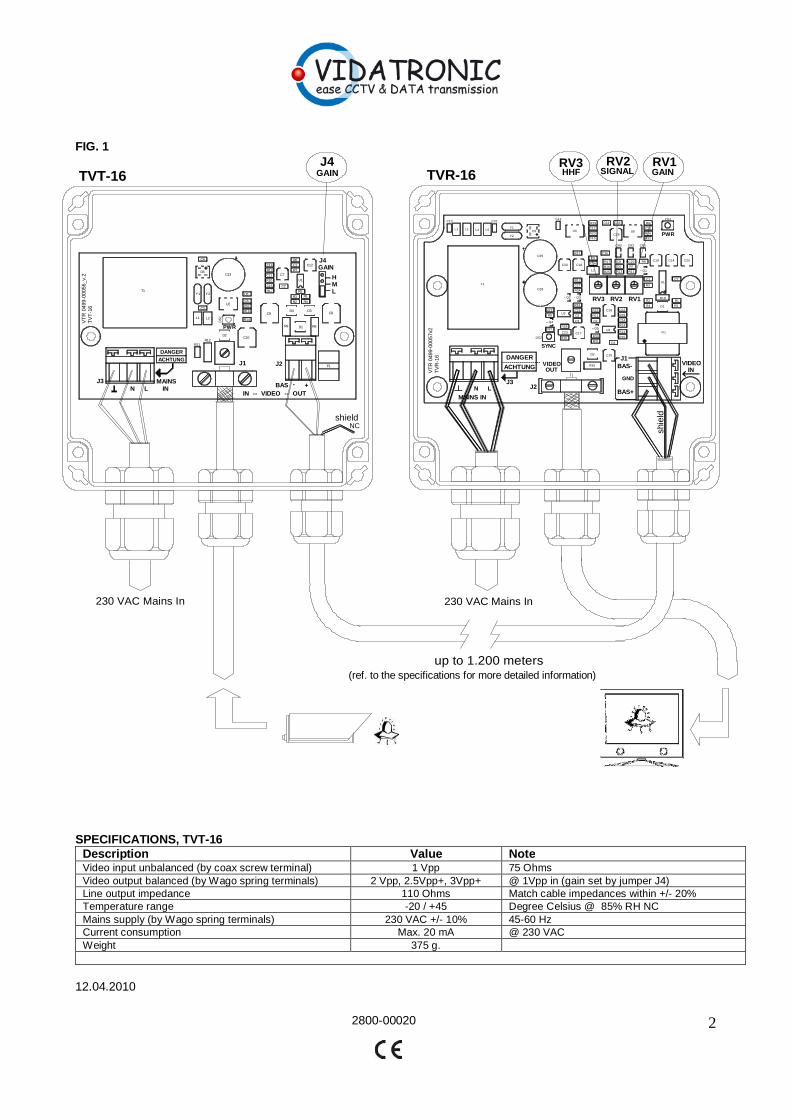
INSTALLATION (ref. to the Fig.1 at page 2)
1) Install the transmitter and the receiver on a flat surface (wall of wood, bricks or like) with the enclosed mounting kit, and with the cable glands downwards.
2) Connect the twisted pair cable to J2 at the transmitter and to J1 at the receiver, “colour-to-colour”. OBS: A possible shield at the UTP cable may ONLY be connected to GND at the receiver site.
3) Connect the camera coax cable to J1 at the transmitter, and the monitor or system cable to J2 at the receiver. Make sure to perform the connection in a secure way.
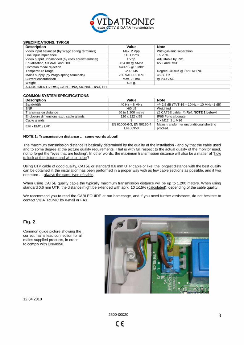
4) Connect the mains cable by Green/Yellow to Earth , Blue to “N” and Brown to “L”. The power cable must be connected to the mains power through a two pole mains switch. The earth wire must be connected to a ground connection in a secure way in order to maintain best possible EMI/EMC safety for the products. NOTE: Refer to FIG.2 at page 3 for correct “anchorin g” of the Mains leads, according to the EN60950.
5) Guideline for gain set (J4) at the transmitter, acc . to the known distances and using CAT5E cable : - 100 to aprx. 600 meters, jumper J4 in pos. “L” - > 600 meters to aprx. 900 meters, jumper J4 in pos. ”M” - > 900 meters, jumper J4 in pos. ”H”
6) With a signal pattern generator connected to the transmitter (disconnect the camera temporarily), adjust the RV1 (Gain), RV2 (Signal) and RV3 (HHF) at the receiver, until you obtain a clean picture with the right colour balance and contrast. Fine adjust eventually the signal output amplitude from the receiver by means of RV1.
7) Replace the pattern generator with the actual camera for that position and eventually perform a fine adjust. NOTE: Make sure that the cable glands have been tightened well, and that all the ¼ turns lock screws at the lid has been locked correctly in ord er to maintain the IP 65 grade.
12.04.2010
2800-00020
2
230 VAC Mains In230 VAC Mains In
up to 1.200 meters(ref. to the specifications for more detailed information)
NC
TVT-16 TVR-16RV3 RV2 RV1J4
GAINSIGNALHHF
GAINJ4
J3
R11R12
J1
D2
DS
1
U2C5
R16R15
R14
C10
C6R17C15
R10C11R13C14
C7
C2
U1
R5R1
R4R2R3
D4 D3
R8D1R9
C9 C8
C12C1R7
R6
C13D5
C4
Y1 Y2
C3
L1 L2
T1
J2 F1
L
IN
+ -
VT
R 0
499-
0005
6_v.
2T
VT
-16
N L
DANGERACHTUNG
MAINS
IN -- VIDEO -- OUTBAS
acac
PWR
MH
GAIN
DS1
J1C15
C4
U3
C16 C22
R29
C24
R15
R14 VT1
R5
R1R2
R4 D1
R18
U1C7
C25C14C19
R32
R16
R6
C32U5
C29
C33C34R19
C13
R20
C12U4
C11
L2
C10
L3 L4
C31
L5
Y2
Y1D3
C35
C30
Q2
C3
C17
J2
R35
D2
R31
R30
Q5
C2
R21
R23
RV3 RV2 RV1
R3
C1
Q1
R9
CR1CR2
C20
R7
R11R13
C6
C8
CR3
C36
R17
R26
R25L1
C26
R24
C9
R37
C18
R12
C27
R34
Q3
R33
C21
C5U2
R10
R28
C23
DS2
R27
Q4
R8
R22
C28
T1
J3
BAS-
BAS+
GND
--------------------ACHTUNG
DANGER
MAINS INN L
VT
R 0
499-
0005
7v2
TV
R-1
6
VIDEOOUT
acac
PWR
VIDEOIN
SYNC
shield
shie
ld
FIG. 1
SPECIFICATIONS, TVT-16
Description Value Note Video input unbalanced (by coax screw terminal) 1 Vpp 75 Ohms Video output balanced (by Wago spring terminals) 2 Vpp, 2.5Vpp+, 3Vpp+ @ 1Vpp in (gain set by jumper J4) Line output impedance 110 Ohms Match cable impedances within +/- 20% Temperature range -20 / +45 Degree Celsius @ 85% RH NC Mains supply (by Wago spring terminals) 230 VAC +/- 10% 45-60 Hz Current consumption Max. 20 mA @ 230 VAC Weight 375 g.
12.04.2010
2800-00020
3
SPECIFICATIONS, TVR-16
Description Value Note Video input balanced (by Wago spring terminals) Max. 2 Vpp With galvanic separation Line input impedance 110 Ohms +/- 20% Video output unbalanced (by coax screw terminal) 1 Vpp. Adjustable by RV1 Equalisation, SIGNAL and HHF >54 dB @ 5Mhz RV2 and RV3 Common mode rejection >40 dB @ 5 Mhz Temperature range -20 / +45 Degree Celsius @ 85% RH NC Mains supply (by Wago spring terminals) 230 VAC +/- 10% 45-60 Hz Current consumption Max. 25 mA @ 230 VAC Weight 425 g. ADJUSTMENTS: RV1, GAIN - RV2, SIGNAL - RV3, HHF
COMMON SYSTEM SPECIFICATIONS
Description Value Note Bandwidth 40 Hz – 8 MHz +/- 2.5 dB (TVT-16 = 10 Hz – 10 MHz -1 dB) SNR >60 dB Weighted Transmission distance 50 to 1.200 metre @ CAT5E cable. *) Ref. NOTE 1 below! Enclosure dimensions excl. cable glands 120 x 122 x 55 IP65 Polycarbonate Cable glands 3 1 x M12, 2 x M16
EMI / EMC / LVD EN 61000-6-3, EN 50130-4 EN 60950
Mains transformer unconditional shorting proofed.
NOTE 1: Transmission distance … some words about! The maximum transmission distance is basically determined by the quality of the installation - and by that the cable used and to some degree at the picture quality requirements. That is with full respect to the actual quality of the monitor used, not to forget the “eyes that are looking”. In other words, the maximum transmission distance will also be a matter of “how to look at the picture, and who to judge”! Using UTP cable of good quality, CAT5E or standard 0.6 mm UTP cable or like, the longest distance with the best quality can be obtained if, the installation has been performed in a proper way with as few cable sections as possible, and if two ore more … always the same type of cable. When using CAT5E quality cable the typically maximum transmission distance will be up to 1.200 meters. When using standard 0.6 mm UTP, the distance might be extended with aprx. 10 to15% (calculated), depending of the cable quality. We recommend you to read the CABLEGUIDE at our homepage, and if you need further assistance, do not hesitate to contact VIDATRONIC by e-mail or FAX. Fig. 2 Common guide picture showing the correct mains lead connection for all mains supplied products, in order to comply with EN60950.
12.04.2010
2800-00020
4
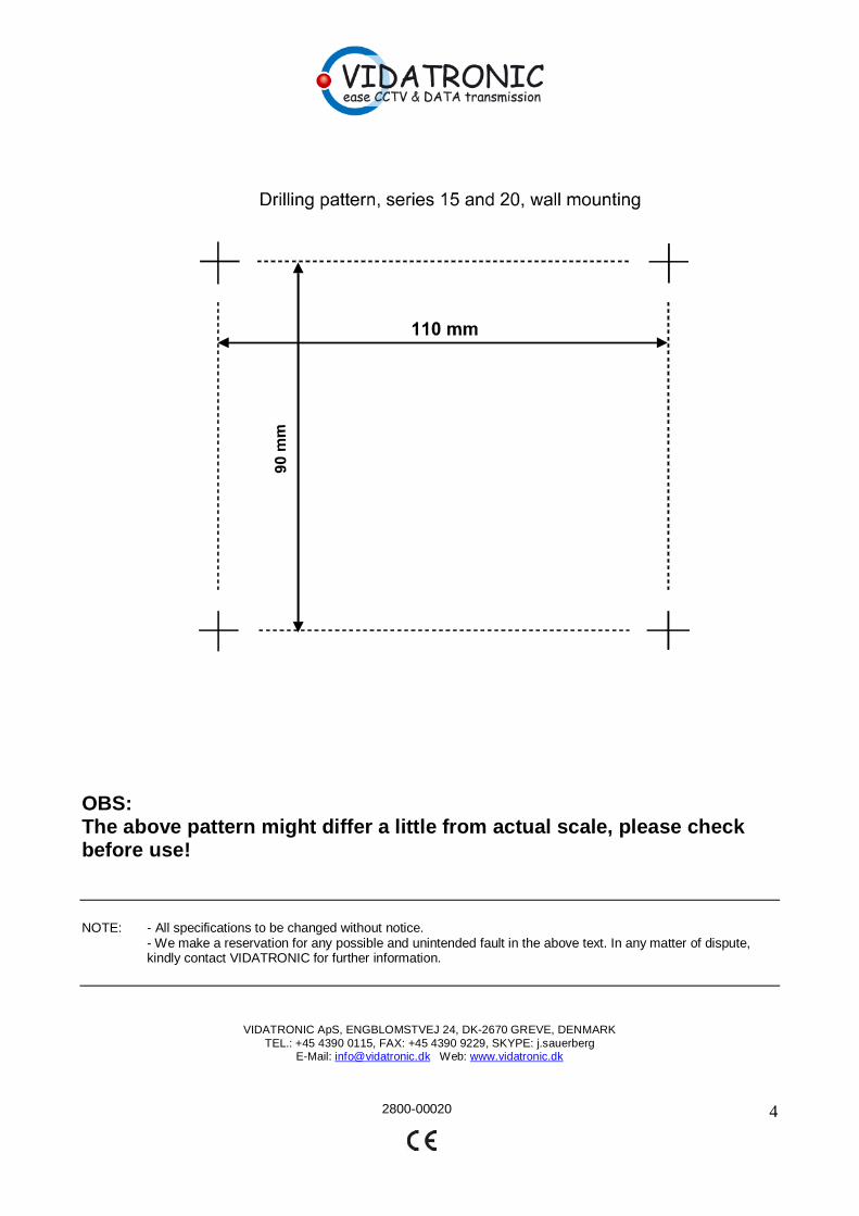
OBS: The above pattern might differ a little from actual scale, please check before use!
NOTE: - All specifications to be changed without notice. - We make a reservation for any possible and unintended fault in the above text. In any matter of dispute, kindly contact VIDATRONIC for further information.
VIDATRONIC ApS, ENGBLOMSTVEJ 24, DK-2670 GREVE, DENMARK TEL.: +45 4390 0115, FAX: +45 4390 9229, SKYPE: j.sauerberg
E-Mail: [email protected] Web: www.vidatronic.dk