Embed Size (px)
Citation preview
43.Acta Geotechnica Slovenica, 2019/1
O. Sivrikaya & G. A. Yazıcı: Two- and three-dimensional analyses of the effect of pile spacing in piled-raft foundations
TWO- AND THREE-DIMEN-SIONAL ANALYSES OF THE EFFECT OF PILE SPACING IN PILED-RAFT FOUNDATIONS
Osman Sivrikaya (corresponding author)Nigde Omer Halisdemir University, Civil Engineering Department,Niğde, 51240, TurkeyE-mail: [email protected]
Gürkan A. Yazıcı Nigde Omer Halisdemir University, Civil Engineering Department,Niğde, 51240, Turkey
Izvleček
Izbira razmika med piloti je eden od pomembnih dejavnikov, ki jih je treba upoštevati pri načrtovanju pilotov povezanih s temeljno blazino. V prispevku so bili na podlagi numeričnih analiz s programskim orodjem PLAXIS, zasnovanim po metodi 2D in 3D končnih elementov, modelirani piloti povezani s temeljno blazino z različnimi konfiguracijami razmika pilotov ter temeljeni na glinenih tleh. Učinek dimenzije je bil preverjen s primerjavo rezultatov analiz 2D in 3D modeliranja. Primerjali in interpretirali smo rezultate modelov z različnimi razmiki med piloti. Skladno z rezultati dvodimenzionalnih in tridimenzionalnih analiz, so se na splošno skupni pomiki ter strižne in volumske specifične deformacije zmanjševale pri povečanju razmikov med piloti (s/D). V primeru s ≥ 6D, kot mejne vrednosti, ni prišlo do bistvene spremembe v zgoraj navedenih količinah (ostale so konstantne) ali pa so se le nekoliko zmanjšale. Ugotovljeno je bilo, da je bila vrednost najve-čjega posedka v 3D analizah večja kot pri 2D analizah. Menimo, da je učinek dimenzije povzročil razlike v rezultatih, dobljenih v 2D in 3D analizah.
DVO IN TRODIMENZIONALNE ANALIZE UČINKA RAZMIKA MED PILOTI POVEZANIMI S TEMELJNO BLAZINO
Ključne besede
piloti povezani s temeljno blazino; razmik med piloti; metoda končnih elementov; nedrenirana analiza
Keywords
piled-raft foundations, pile spacing, finite-element method, undrained analysis
DOI https://doi.org/10.18690/actageotechslov.16.1.43-52.2019
Abstract
One of the important factors that have to be considered in the design of piled-raft foundations is the selection of the spacing between the piles. In this study, a piled-raft foun-dation having different pile-spacing configurations and resting on clayey soil was modeled using PLAXIS nume-rical packages based on the 2D and 3D finite-element methods. The dimension effect is examined by comparing the 2D modeling analysis with the 3D modeling analysis. The results of the models with different pile spacings were compared and interpreted. As a general trend in accordance with the results of the two- and three-dimen-sional analyses, the total displacements, shear strains and volumetric strains decreased as the pile spacings (s/D) increased. In the case of s ≥ 6D as a threshold value there was no significant change in the aforementioned quantities (they remain constant) or decreased slightly. The maximum settlement was found to be greater in the 3D analyses than in the 2D analyses. It is thought that the dimension effect caused the differences in the results obtained with the 2D and 3D analyses.
44. Acta Geotechnica Slovenica, 2019/1
1 INTRODUCTION
In engineering computations, in addition to safety, economical designs are also of great concern. This particular case is realized especially when the loads coming from the superstructure are of the order of greater magnitudes where the foundation system design requires economy next to safety. In many cases, piles are used in groups to transmit the structural loads to the soil. A pile cap is constructed on the group of piles. The pile cap can be well above the ground or in contact with the surface. The design principle of pile groups also applies to piled rafts [1]. Piled-raft systems are of impor-tance for such cases where the base pressure beneath the footing is shared by the raft and the pile. Based on this fact, piled-raft systems, where the interactions among the pile, the raft and the soil are taken into consider-ation, are becoming more frequently used.
Piles may be installed under a raft for the purpose of reducing settlements [2]. Piled-raft foundations also contribute to avoiding differential settlements [3]. In addition, they reduce the magnitude of the internal stress and the bending moments in the raft. However, the biggest drawback is to model the interactions among the pile, the raft and the soil. In these cases, it is better to model with numerical methods, such as the finite-element method (FEM) [4, 5, 6].
For the settlement calculation of pile groups, there are several approaches, including, empirical, analytical and numerical methods. These methods can be classified as follows:
– Methods based on empirical formulations [7, 8]– Approaches that take into account soil-structure
interaction stress superposition [9]– Methods based on modifying the load-settlement
curves for individual piles by group-interaction factors [10]
– The equivalent raft method based on the assumption that the piles are represented by an imaginary raft resting at a specific depth [11]
– The pile group and the soil inside the pile group are regarded as a block and solved as an individual pile, where the rigidity of the pile and the soil is calculated and an average value is obtained [12]
– Numerical methods such as the finite-elements method (FEM) and the finite-difference method (FDM), etc.[13, 14]
1.1 Settlement of piled rafts in cohesionless soils
The settlement of a pile group (Sg) is normally greater than the settlement of a single pile (St) at an equal load
O. Sivrikaya & G. A. Yazıcı: Two- and three-dimensional analyses of the effect of pile spacing in piled-raft foundations
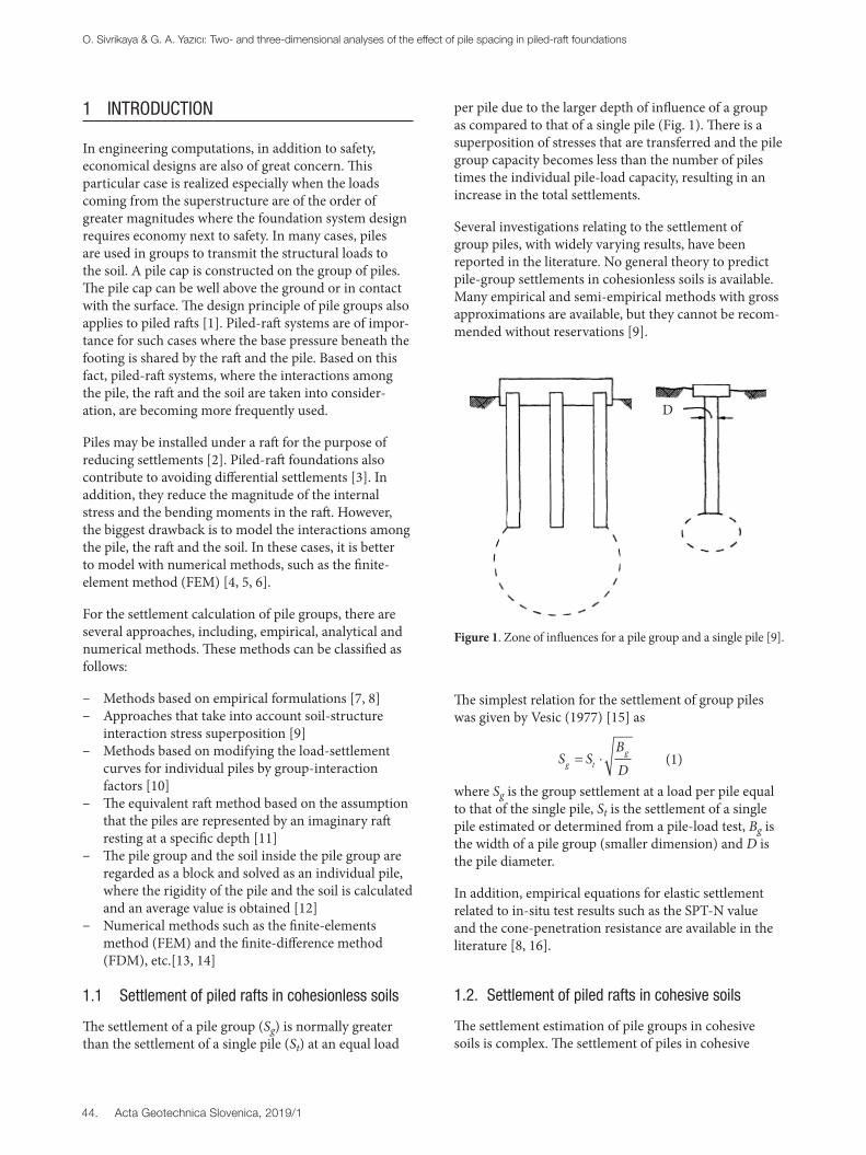
per pile due to the larger depth of influence of a group as compared to that of a single pile (Fig. 1). There is a superposition of stresses that are transferred and the pile group capacity becomes less than the number of piles times the individual pile-load capacity, resulting in an increase in the total settlements.
Several investigations relating to the settlement of group piles, with widely varying results, have been reported in the literature. No general theory to predict pile-group settlements in cohesionless soils is available. Many empirical and semi-empirical methods with gross approximations are available, but they cannot be recom-mended without reservations [9].
Figure 1. Zone of influences for a pile group and a single pile [9].
The simplest relation for the settlement of group piles was given by Vesic (1977) [15] as
S SBDg t
g= ⋅ (1)
where Sg is the group settlement at a load per pile equal to that of the single pile, St is the settlement of a single pile estimated or determined from a pile-load test, Bg is the width of a pile group (smaller dimension) and D is the pile diameter.
In addition, empirical equations for elastic settlement related to in-situ test results such as the SPT-N value and the cone-penetration resistance are available in the literature [8, 16].
1.2. Settlement of piled rafts in cohesive soils
The settlement estimation of pile groups in cohesive soils is complex. The settlement of piles in cohesive
D
45.Acta Geotechnica Slovenica, 2019/1
soils primarily consists of the sum of the short-term settlement occurring as the load is applied and the long-term consolidation settlement occurring gradually as the excess pore pressures generated by the loads are dissipated. Generally, the short-term settlement results from the elastic compression of cohesive soils. This component of the settlement constitutes a significant portion of the total settlement for partially saturated and over-consolidated saturated cohesive soils [9].
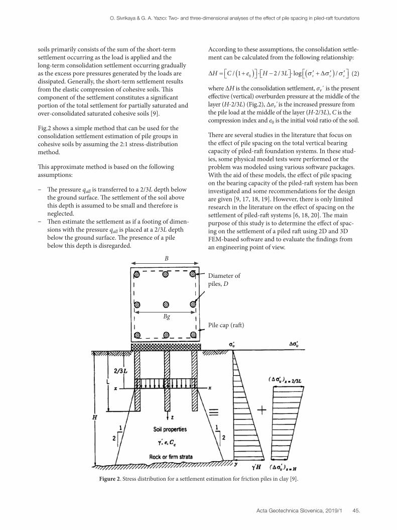
Fig.2 shows a simple method that can be used for the consolidation settlement estimation of pile groups in cohesive soils by assuming the 2:1 stress-distribution method.
This approximate method is based on the following assumptions:
– The pressure qall is transferred to a 2/3L depth below the ground surface. The settlement of the soil above this depth is assumed to be small and therefore is neglected.
– Then estimate the settlement as if a footing of dimen-sions with the pressure qall is placed at a 2/3L depth below the ground surface. The presence of a pile below this depth is disregarded.
O. Sivrikaya & G. A. Yazıcı: Two- and three-dimensional analyses of the effect of pile spacing in piled-raft foundations
Figure 2. Stress distribution for a settlement estimation for friction piles in clay [9].
According to these assumptions, the consolidation settle-ment can be calculated from the following relationship:
∆ ∆H C e H L v v v= +( ) ⋅ − ⋅ ′ + ′( ) ′ / / log /1 2 30 σ σ σ (2)
where ΔH is the consolidation settlement, σv´ is the present effective (vertical) overburden pressure at the middle of the layer (H-2/3L) (Fig.2), Δσv' is the increased pressure from the pile load at the middle of the layer (H-2/3L), C is the compression index and e0 is the initial void ratio of the soil.
There are several studies in the literature that focus on the effect of pile spacing on the total vertical bearing capacity of piled-raft foundation systems. In these stud-ies, some physical model tests were performed or the problem was modeled using various software packages. With the aid of these models, the effect of pile spacing on the bearing capacity of the piled-raft system has been investigated and some recommendations for the design are given [9, 17, 18, 19]. However, there is only limited research in the literature on the effect of spacing on the settlement of piled-raft systems [6, 18, 20]. The main purpose of this study is to determine the effect of spac-ing on the settlement of a piled raft using 2D and 3D FEM-based software and to evaluate the findings from an engineering point of view.
Diameter of piles, D
Pile cap (raft)
B
Bg

46. Acta Geotechnica Slovenica, 2019/1
2 FINITE-ELEMENT MODELING
2.1 Finite-element mesh and boundary conditions
The behavior of the piled raft was examined in terms of the effect of the pile spacings by performing 2D and 3D numerical analyses. The finite-element package PLAXIS was used as a calculation tool. PLAXIS is a software program based on the finite-element method that is widely used in geotechnical engineering applications to analyze soil behavior with soil models [21, 22]. It is used in geotechnical application areas such as deep excavation and support systems, shallow and deep foundations, retaining structures, geotextile-reinforced and non-
Figure 3. a) 2D model used in the analyse b) 3D model used in the analyses.
reinforced filler constructions, soil improvements, as well as dam and tunnel designs [23-28]. Figure 3 shows typical 2D and 3D FE meshes used in these parametric analyses. The piles were taken to be 0.6 m in diameter D and 18 m in length Lp. A square raft with a width B of 20 m (thickness, 1 m) was considered. The pile cap and the raft were considered as rigidly connected to each other. The raft–soil interface was considered to be rigid within a contact zone. Since the mobilization of the friction between the bored pile of the rough concrete shell and the clayey soil occurs in a short period of time after manufacture the interface properties are also assigned as rigid. The mesh was assumed to be on a rigid layer beyond the boundaries, and the vertical boundaries on the left- and right-hand sides were assumed to be on rollers to allow the downward movement of the soil layers. For the far-field boundaries, the distance of the boundary from the edge of the raft was set to 50 m, since the observed influence zone based on the finite-element analysis including interface was at most 8–10 m. After an initial equilibrium, the vertical loading was applied on the top of the raft surface. Since the modeling of the entire pile-installation process is rather complicated, the pile was assumed to be in a stress-free state at the start of the analysis. The stress change in the soil during the pile installation was therefore not included.
In the 3D model of the soil and the piled raft, the geom-etry was divided into 15-node wedge elements. These elements were composed of the 6-node triangular faces in the workplanes, as generated by the 2D mesh genera-tion [21, 22].
Choosing a larger number of elements where there is a high anticipated stress and/or the possibility of critical settlement behavior gives more precise results. Local mesh refinement in such zones is preferred, instead of choosing an equal mesh size, because it saves computational time. A relatively fine mesh was used near the pile–soil and raft–soil interfaces, while a coarser mesh was used further from the pile and the raft (Fig. 4 and Fig. 5).
The system of analysis should consist of a geometry that is sufficiently large in the x, y and z directions in order not to be influenced by the boundary conditions. In this context, it was found that by choosing a geometry of 50 m × 50 m for the 2D, and 50 m × 50 m × 50 m for the 3D models, the above-mentioned interactions from the boundary values were minimized (Fig. 3).
2.2 Constitutive modeling
The over-consolidated clay was considered as the soil material and the behavior of this layer was modeled with the hardening soil model, which gives more accurate
O. Sivrikaya & G. A. Yazıcı: Two- and three-dimensional analyses of the effect of pile spacing in piled-raft foundations
47.Acta Geotechnica Slovenica, 2019/1
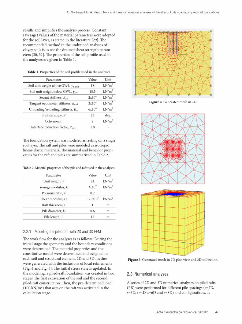
results and simplifies the analysis process. Constant (average) values of the material parameters were adopted for the soil layer, as stated in the literature [29]. The recommended method in the undrained analyses of clayey soils is to use the drained shear strength param-eters [30, 31]. The properties of the soil profile used in the analyses are given in Table 1.
Parameter Value UnitSoil unit weight above GWL, γunsat 18 kN/m3
Soil unit weight below GWL, γsat 18.5 kN/m3
Secant stiffness, E50 2x10⁴ kN/m2
Tangent oedometer stiffness, Eoed 2x10⁴ kN/m2
Unloading/reloading stiffness, Eur 6x10⁴ kN/m2
Friction angle, ø' 25 deg.Cohesion, c' 2 kN/m2
Interface reduction factor, Rinter 1.0 -
Table 1. Properties of the soil profile used in the analyses.
The foundation system was modeled as resting on a single soil layer. The raft and piles were modeled as isotropic linear-elastic materials. The material and behavior prop-erties for the raft and piles are summarized in Table 2.
Parameter Value UnitUnit weight, γ 24 kN/m3
Young’s modulus, E 3x10⁷ kN/m2
Poisson’s ratio, ν 0.2 -
Shear modulus, G 1.25x10⁷ kN/m2
Raft thickness, t 1 mPile diameter, D 0.6 m
Pile length, L 18 m
Table 2. Material properties of the pile and raft used in the analyses.
2.2.1 Modeling the piled raft with 2D and 3D FEM
The work flow for the analyses is as follows. During the initial stage the geometry and the boundary conditions were determined. The material properties and the constitutive model were determined and assigned to each soil and structural element. 2D and 3D meshes were generated with the inclusions of local refinements (Fig. 4 and Fig. 5). The initial stress state is updated. In the modeling, a piled-raft foundation was created in two stages: the first excavation of the soil and the second piled-raft construction. Then, the pre-determined load (100 kN/m2) that acts on the raft was activated in the calculation stage.
2.3. Numerical analyses
A series of 2D and 3D numerical analyses on piled rafts (PR) were performed for different pile spacings (s=2D, s=3D, s=4D, s=6D and s=8D) and configurations, as
Figure 4. Generated mesh in 2D.
Figure 5. Generated mesh in 2D plan view and 3D utilization.
O. Sivrikaya & G. A. Yazıcı: Two- and three-dimensional analyses of the effect of pile spacing in piled-raft foundations
48. Acta Geotechnica Slovenica, 2019/1
shown in Fig.6. The piles were taken to be 0.6 m in diam-eter (D) and 18 m (floating) in length (Lp). A square raft with a width B of 20 m (thickness, 1 m) was considered.
Figure 6. Analyzed cases for s=2D, s=3D, s=4D, s=6D and s=8D.
In this study, attention was focused on the undrained (short-term) response of a piled raft resting on an over-consolidated clay layer. As recommended by the literature, the clay was idealized using the drained shear strength parameters, c' and ϕ' (Table 1). Constant values of the drained Young’s modulus and the drained shear strength parameters were adopted for the soil layer. For the structural components, the pile was based on a typical reinforced concrete pile and modeled with a solid section. The raft was assigned general concrete material parameters. Table 2 summarizes the material parameters used in the analyses. The loads transmitted from the superstructure were modeled as a uniformly distributed loading (i.e., uniform loading) and the load was assumed to be 1.5-times the load on the area of 20 m × 20 m (base pressure of 100 kPa) (Fig. 6). All the analyses were carried out under undrained conditions.
In this study, the 2D and 3D analyses of a piled-raft system under a vertical load were performed with respect to the short term. Their behaviors were exam-ined and compared in accordance with 2D and 3D analyses. The raft in the piled-raft system was considered to be in contact with soil in the analyses. In this study five different piled-raft foundations were analyzed in plane strain (2D) and three dimensions (3D), which makes a total of 10 cases (Fig.6).
3 COMPUTED RESULTS AND DISCUSSION
3.1 Analyses of the 2D models
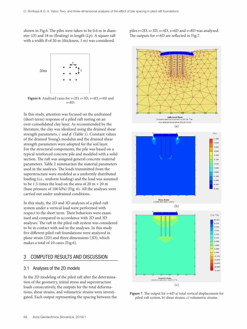
In the 2D modeling of the piled raft after the determina-tion of the geometry, initial stress and superstructure loads consecutively, the outputs for the total deforma-tions, shear strains, and volumetric strains were investi-gated. Each output representing the spacing between the
piles s=2D, s=3D, s=4D, s=6D and s=8D was analyzed. The outputs for s=6D are reflected in Fig.7.
Figure 7. The output for s=6D a) total vertical displacement for piled-raft system, b) shear strains, c) volumetric strains.
s
s20m
(b)
(a)
(c)
O. Sivrikaya & G. A. Yazıcı: Two- and three-dimensional analyses of the effect of pile spacing in piled-raft foundations
49.Acta Geotechnica Slovenica, 2019/1
The maximum vertical displacement for the 2D calcula-tions was calculated as 18.31 mm, representing the axial spacing s=2D. The minimum vertical displacement was found to be 11.44 mm, representing the axial spacing s=8D. The shear strains were calculated to be in the range 1.71–3.20 % and they reach a maximum at the raft edges and fade near the pile shaft. The maximum value for the shear strains was calculated to be 3.20 %, representing s=3D. The highest volumetric strains were calculated to locate near the pile-raft connection locations. The maximum volumetric strain value was calculated to be 0.024 % for the axial spacing of s=8D. Values between 0.015 % and 0.024 % were obtained at the pile tip location level.
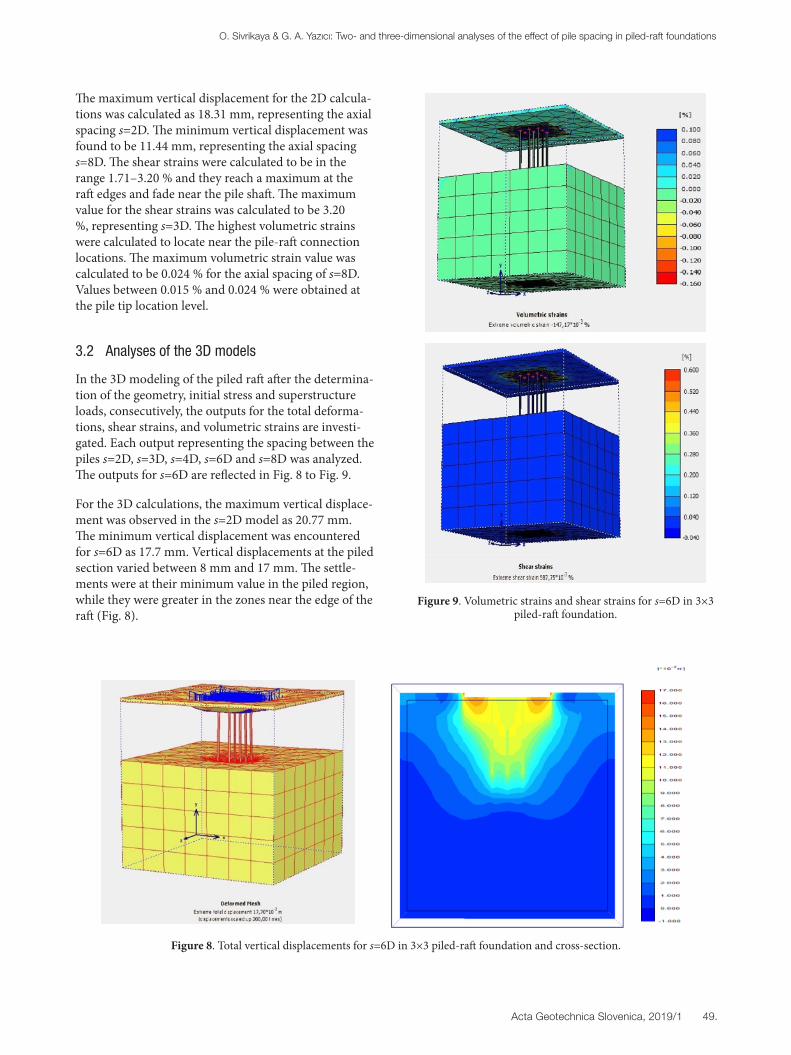
3.2 Analyses of the 3D models
In the 3D modeling of the piled raft after the determina-tion of the geometry, initial stress and superstructure loads, consecutively, the outputs for the total deforma-tions, shear strains, and volumetric strains are investi-gated. Each output representing the spacing between the piles s=2D, s=3D, s=4D, s=6D and s=8D was analyzed. The outputs for s=6D are reflected in Fig. 8 to Fig. 9.
For the 3D calculations, the maximum vertical displace-ment was observed in the s=2D model as 20.77 mm. The minimum vertical displacement was encountered for s=6D as 17.7 mm. Vertical displacements at the piled section varied between 8 mm and 17 mm. The settle-ments were at their minimum value in the piled region, while they were greater in the zones near the edge of the raft (Fig. 8).
Figure 9. Volumetric strains and shear strains for s=6D in 3×3 piled-raft foundation.
Figure 8. Total vertical displacements for s=6D in 3×3 piled-raft foundation and cross-section.
O. Sivrikaya & G. A. Yazıcı: Two- and three-dimensional analyses of the effect of pile spacing in piled-raft foundations
50. Acta Geotechnica Slovenica, 2019/1
The magnitude of the shear strains in the system varied in the range 0.82–0.58 %. The maximum values were encountered around the pile-raft connection region. The maximum volumetric strain value reached 0.152 % for the s=2D axial spacing model. Values ranging between 0.152 % and 0.127 % were obtained at the zone around the pile tip (Fig. 9).
3.3. Comparison of results for the 2D and 3D model-ing analyses
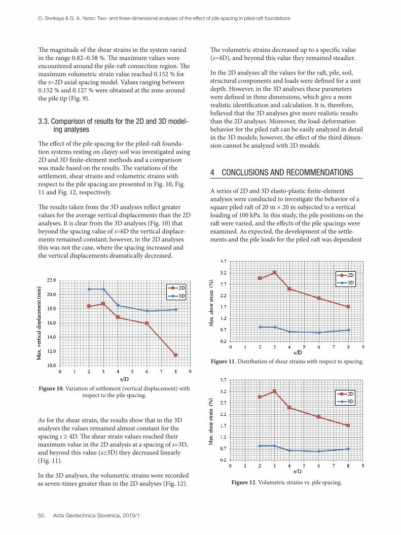
The effect of the pile spacing for the piled-raft founda-tion systems resting on clayey soil was investigated using 2D and 3D finite-element methods and a comparison was made based on the results. The variations of the settlement, shear strains and volumetric strains with respect to the pile spacing are presented in Fig. 10, Fig. 11 and Fig. 12, respectively.
The results taken from the 3D analyses reflect greater values for the average vertical displacements than the 2D analyses. It is clear from the 3D analyses (Fig. 10) that beyond the spacing value of s=6D the vertical displace-ments remained constant; however, in the 2D analyses this was not the case, where the spacing increased and the vertical displacements dramatically decreased.
Figure 10. Variation of settlement (vertical displacement) with respect to the pile spacing.
Figure 11. Distribution of shear strains with respect to spacing.
The volumetric strains decreased up to a specific value (s=4D), and beyond this value they remained steadier.
In the 2D analyses all the values for the raft, pile, soil, structural components and loads were defined for a unit depth. However, in the 3D analyses these parameters were defined in three dimensions, which give a more realistic identification and calculation. It is, therefore, believed that the 3D analyses give more realistic results than the 2D analyses. Moreover, the load-deformation behavior for the piled raft can be easily analyzed in detail in the 3D models; however, the effect of the third dimen-sion cannot be analyzed with 2D models.
4 CONCLUSIONS AND RECOMMENDATIONS
A series of 2D and 3D elasto-plastic finite-element analyses were conducted to investigate the behavior of a square piled raft of 20 m × 20 m subjected to a vertical loading of 100 kPa. In this study, the pile positions on the raft were varied, and the effects of the pile spacings were examined. As expected, the development of the settle-ments and the pile loads for the piled raft was dependent
As for the shear strain, the results show that in the 3D analyses the values remained almost constant for the spacing s ≥ 4D. The shear strain values reached their maximum value in the 2D analysis at a spacing of s=3D, and beyond this value (s≥3D) they decreased linearly (Fig. 11).
In the 3D analyses, the volumetric strains were recorded as seven-times greater than in the 2D analyses (Fig. 12). Figure 12. Volumetric strains vs. pile spacing.
O. Sivrikaya & G. A. Yazıcı: Two- and three-dimensional analyses of the effect of pile spacing in piled-raft foundations
51.Acta Geotechnica Slovenica, 2019/1
on the pile–soil interface and the pile spacing.
In this study, the effect of the spacing of the piles in piled-raft systems resting on clayey soil was investigated by means of a literature survey, 2D and 3D FEM analyses and these results were obtained:
– The major parameters that define the load-settlement behavior are geometrical properties such as the area of the piled region/area of the raft, or the pile group dimension/raft dimension, the pile spacing, and the pile length. Various researchers recommend opti-mum values for these parameters.
– It is more realistic and convenient to utilize 3D FEM analysis to design the piled raft due to using the original dimensions of the soil and the structural elements in the calculation stage.
– The shear strains reached their maximum value at the edge of the raft and dissipated at the lower eleva-tions of the other piles.
– The volumetric and shear strains remained steady beyond a specific value of the spacing (s=4D)
– The settlements reduced dramatically beyond a certain spacing value (s=6D) in the 2D analysis. However, they were reduced and remained constant in the 3D analyses to a specific spacing value (s=6D) and remained constant beyond that value.
– The vertical-displacement and the volumetric-strain results were greater in the (3D) analyses than in the 2D analyses.
– It is considered that the differences of the results obtained from 2D and 3D analysis come from the dimension effect and the analysis type.
REFERENCES
[1] Z[1] Randolph, M.F. 1994. Design Methods for Pile Groups and Piled Rafts. Proceedings of 13th
International Conference of Soil Mechanics and Foundation Engineering, New Delhi, 61-82.
[2] Reul, O., Randolph, M.F. 2004. Design strategies for piled rafts subjected to non-uniform vertical loading. Journal of Geotechnical and Geoenvi-ronmental Engineering 130, 1, 1-13. https://doi.org/10.1061/(ASCE)1090-0241(2004)130:1(1)
[3] Kim, K.N., Lee, S.H., Kim, K.S., Chung, C.K., Kim, M.M., Lee, H.S. 2001. Optimal pile arrangement for minimizing differential settlements in piled raft foundations. Computers and Geotechnics 28, 4, 235-253. https://doi.org/10.1016/S0266-352X(01)00002-7
[4] Pressley, J.S., Poulos, H.G. 1986. Finite element analysis of mechanics of pile group behavior.
International Journal for Numerical and Analytical Methods in Geomechanics 10, 2, 213-221. https://doi.org/10.1002/nag.1610100208
[5] Gök, S. 2007. Design of piled raft foundations. Ph.D.Thesis. İstanbul Technical University, İstanbul, Turkey.
[6] Kalpakcı, V., Özkan, M.Y. 2012. A simplified approach to the settlement estimation of piled rafts. Acta Geotechnica Slovenica 9, 1, 77-85.
[7] Vesic, A.S. 1970. Load Transfer in Pile Soil Systems. Proceeding Conference and Design Installation of Piled Foundations, Lehigh University, Bethlehem, 47-73.
[8] Meyerhof, G.G. 1976. Bearing capacity and settlement of pile foundations. ASCE Journal of the Geotechnical Engineering Division 102, 3, 195-228.
[9] Poulos, H.G., Davis, E.H. 1980. Pile Foundation Analysis and Design. John Wiley: New York.
[10] Chow, Y.K. 1986. Analysis of vertically loaded pile groups. International Journal for Numerical and Analytical Methods in Geomechanics 10, 1, 59-72. https://doi.org/10.1002/nag.1610100105
[11] Castelli, F., Maugeri, M. 2002. Simplified Nonlinear Analysis for Settlement Prediction of Pile Groups. ASCE Journal of Geotechnical and Geoenviron-mental Engineering 128, 1, 76-84. https://doi.org/10.1061/(ASCE)1090-0241(2002)128:1(76)
[12] Poulos, H.G. 2002. Prediction of Behavior of Build-ing Foundations due to Tunneling Operations. Proc. 3rd Int. Symp. On Geot. Aspects of Tunneling in Soft Ground, Toulouse, 4, 55-61.
[13] Reul, O., Randolph, M.F. 2003. Piled rafts in overconsolidated clay: comparison of in situ measurements and numerical analyses. Geotech-nique 53, 3, 301-315. https://doi.org/10.1680/geot.2003.53.3.301
[14] Prakoso, W.A., Kulhawy, F.H. 2001. Contribution to piled raft optimum design, ASCE Journal of Geotechnical and Geoenvironmental Engineering 127, 1, 17-24. https://doi.org/10.1061/(ASCE)1090-0241(2001)127:1(17)
[15] Vesic, A.S. 1977. Design of Pile Foundations. Transportation Research Board, National ResearchCouncil.
[16] Skempton, A.W. 1953. Discussion on Piles and Pile Foundation. Proceedings 3rd International Confer-ence on Soil Mechanics and Foundation Engineer-ing, Zurich, Switzerland, 3, 172.
[17] Kishida, H., Meyerhof, G.G. 1965. Bearing Capac-ity of Pile Groups under Eccentric Loads in Sand, Proc. Fifth Int. Conf. Soil Mech. 2, 270-274.
[18] Brand, E.W., Muktabhant, C., Taechathummarak, A.1972. Load tests on small foundation in soft clay.
O. Sivrikaya & G. A. Yazıcı: Two- and three-dimensional analyses of the effect of pile spacing in piled-raft foundations

52. Acta Geotechnica Slovenica, 2019/1
Proc.ASCE Conf. on Performance of Earth and Earth Supported Structures, Purdue University, 1, 2, 903–928.
[19] Engin, H.K., Septanika, E.G., Brinkgreve, R.B.J. 2008. Estimation of pile group behavior using embedded piles, The 12th International Conference of International Association for Computer Meth-ods and Advances in Geomechanics. Goa, India, 3231-3238.
[20] Comodromos, E.M., Papadopoulos, M.C., Rentzeperis, I.K. 2009. Pile foundation analysis and design using experimental data and 3-D numerical analysis. Computers and Geotech-nics 36, 5, 819-836. https://doi.org/10.1016/j.compgeo.2009.01.011
[21] Brinkgreve, R.B.J., Broere, W. 2006. Plaxis 3D Foundation V1.6 Manual, Delft University, Nether-lands.
[22] Brinkgreve, R.B.J, Engin, E., Swolfs, W.M. 2014. Plaxis 2014 Manuals, Delft University of Technol-ogy, The Netherlands, ISBN-13: 978-90-76016-15-3.
[23] Athania, S.S., Solankia, C.H., Dodagoudarb, G.R. 2015. Seepage and stability analyses of earth dam using finite element method. Aquatic Procedia 4, 876-883. https://doi.org/10.1016/j.aqpro.2015.02.110
[24] Houari, N., Allal, M.A., Bekr, N.A. 2011. Numeri-cal Simulation of the Mechanical Response of the Tunnels in the Saturated Soils by Plaxis. Jordan Journal of Civil Engineering 5, 1, 9-31.
[25] Kasim, F., Martob, A., Othman B.A., Bakar, I., Othmane, M.F. 2013. Simulation of safe height embankment on soft ground using Plaxis, APCBEE Procedia 152-156, 2013. https://doi.org/10.1016/j.apcbee.2013.05.027
[26] Likitlersuang, S., Surarak, C., Wanatowski, D., Oh, E., Balasubramaniam, A. 2013. Finite element analysis of a deep excavation: A case study from the Bangkok MRT. Soils and Founda-tions 53, 5, 756-773. https://doi.org/10.1016/j.sandf.2013.08.013
[27] Salimath, R.S., Pender, M.J. 2015. Moment-rotation behavior of shallow foundations with fixed vertical load using PLAXIS 3D. 6th International Confer-ence on Earthquake Geotechnical Engineering, Christchurch, New Zealand, 1-4 November.
[28] Sanjei, C., Silva, L.I.N. 2015. Numerical analysis of the backfilling sequence effect on gravity retaining wall behavior. 6th International Conference on Structural Engineering and Construction Manage-ment, Kandy, Sri Lanka, 11-13 December.
[29] Sert, S. 2003. Three-Dimensional (3D) analysis of piled raft foundations on alluvial environments.
Ph.D. Thesis, Sakarya University, Sakarya, Turkey.[30] Berilgen, M. 2010. Computational Geotechnical
Course with Plaxis. Istanbul Culture University, 24 - 26 May, Istanbul, Turkey.
[31] Brinkgreve, R.B.J. 2014. PLAXIS Version 8, Materi-als Models Manual 2, Delft University of Technol-ogy, The Netherlands.
O. Sivrikaya & G. A. Yazıcı: Two- and three-dimensional analyses of the effect of pile spacing in piled-raft foundations