Embed Size (px)
Citation preview
Ultrasonics 119 (2022) 106554
Available online 20 August 20210041-624X/© 2021 Elsevier B.V. All rights reserved.
Two-dimensional scattering features of the mixed second harmonic A0 mode Lamb waves for incipient damage localization
Shengbo Shan a,b,c, Li Cheng a,b,c,*
a Department of Mechanical Engineering, The Hong Kong Polytechnic University, Kowloon, Hong Kong Special Administrative Region b The Hong Kong Polytechnic University Shenzhen Research Institute, Shenzhen 518057, China c Hong Kong Branch of National Rail Transit Electrification and Automation Engineering Technology Research Center, The Hong Kong Polytechnic University, Kowloon, Hong Kong Special Administrative Region
A R T I C L E I N F O
Keywords: Incipient damage Damage localization Mode mixing Nonlinear Lamb wave
A B S T R A C T
Inspection of incipient structural damage is of great significance. Existing techniques based on nonlinear guided waves have shown great promise for the detection of incipient damage due to material microstructure changes, but with only limited success for damage localization, which is technically more challenging. Our previous work uncovered the existence of the second harmonic A0 mode Lamb waves in a PZT-driven system, as a result of the mixing of the primary A0 and S0 mode Lamb waves, thus pointing at the possibility of performing damage localization through tuning the size of the wave mixing zone. In the present study, a two-dimensional incipient damage localization method is proposed based on this newly discovered wave phenomenon. By visualizing the nonlinear wave field, damage-induced nonlinear wave scattering features are first investigated. A dedicated localization algorithm is then proposed and evaluated. Numerical results show that the energy of the scattered nonlinear wave is mainly confined to a narrow region along the actuator-damage path, the spatial variation of which can be approximated by a simple Gaussian function. Embedding this information into the proposed localization strategy, damage localization can be achieved using a simple physical system. Experiments are finally carried out to validate the 2nd A0 wave scattering features and the proposed damage localization method.
1. Introduction
Structural damage in mechanical systems may lead to catastrophic failures during their operation. Prior to the occurrence of macro struc-tural damage like cracks, plastic deformation, etc., materials usually undergo a continuous degradation process which acts as a damage precursor. For metallic structures, this process is closely linked to the changes/degradations in their nonlinear elastic properties which can be further regarded as the structural incipient damage. Therefore, suc-cessful monitoring of such incipient damage can significantly shift the maintenance schedule to an earlier stage which in turn, enhances the operational safety of the structures [1-4].
Nonlinear-guided-wave-based damage inspection methods have been shown to exhibit high sensitivity to incipient damage through detecting material nonlinear elastic effects or contact acoustic non-linearities via monitoring subharmonics [5-7], higher harmonics, [8-13] or modulation/wave mixing [14-18] of the excitation frequencies of the probing signals. For example, Xiang et.al. monitored the thermal
degradation in a steel plate with the second harmonic Lamb waves [19]. Cho et.al. developed a technique to use counter-propagating SH wave mixing to generate a nonlinear Lamb wave for characterizing fatigue damage in aluminum plates[20]. Patra et.al. experimentally observed the dissipated nonlinearity with nonlinear Lamb waves due to stress- relaxation in composites [21]. More examples and applications target-ing different types of incipient damage in various materials have also been reported in the open literature [2,19,22-28]. Most existing works, however, focused on detection, instead of localization. Indeed, as a higher level of damage inspection, the localization of incipient damage is technically challenging. While readily achievable for large damage using linear wave phenomena, its investigation in the context of nonlinear-guided-waves for incipient damage is much less and largely insufficient. Among a few reported works, one can mention the time-of- flight-based imaging method which is derived from its linear counter-part. This was made possible by conducting short-time Fourier transform on higher order wave components to preserve the temporal information on the damage-induced nonlinear wave scattering [7,29]. The efficacy
* Corresponding author at: Department of Mechanical Engineering, The Hong Kong Polytechnic University, Kowloon, Hong Kong Special Administrative Region. E-mail address: [email protected] (L. Cheng).
Contents lists available at ScienceDirect
Ultrasonics
journal homepage: www.elsevier.com/locate/ultras
https://doi.org/10.1016/j.ultras.2021.106554 Received 9 February 2021; Received in revised form 24 May 2021; Accepted 13 August 2021
Ultrasonics 119 (2022) 106554
2
of the method was demonstrated for a crack [29] and a disbond [7], which are different from the incipient damage associated with material nonlinearity to be investigated in this work, presumably much less visible, smaller in effects of wave scattering and therefore more difficult to be detected. As another example, the concept of tomography widely used in the linear-guided-wave-based technique has also been extended to the nonlinear regime by synthesizing damage information from multiple actuator-sensor paths [30]. Such method, however, requires a dense transducer network to ensure a good localization resolution, increasing the complexity of the monitoring system. As an alternative, wave mixing technique has also been used for incipient damage locali-zation [22]. By tuning the location of the mixing zone of a pair of guided waves, zone-by-zone damage detection was achieved. The method re-quires two independent channels for simultaneous wave generation, thus setting up a harsh demand for the measurement system in terms of signal generation and synchronization. Moreover, the method becomes extremely cumbersome for two-dimensional (2D) inspection due to the difficulty in controlling the mixing zone in a 2D scenario and in deter-mining the proper sensor placement as a result of complex 2D mixing angle combinations [31,32].
Recently, a new type of second harmonic A0 mode Lamb wave (2nd A0 wave) has been discovered in our previous work, which offers new possibilities for incipient damage location [33]. The reported wave component results from the mixing of the primary S0 and A0 waves, which can be generated by one single actuator. Furthermore, the wave mixing zone can be tactically controlled through adjusting the wave excitation duration, which hatches out a zone-by-zone incipient damage inspection strategy along the wave propagation direction for damage localization. Though this can be readily achieved in the one-dimensional (1D) case, it is unclear whether 2D localization is possible due to the foreseeable increasing complexity in the wave propagation and scat-tering in the presence of the incipient damage. Therefore, there is an interest in gaining an in-depth understanding of the damage-induced scattering features of the newly discovered 2nd A0 waves and the way they affect the design of damage localization algorithms and sensor configurations. Motivated by this, this work is carried out with a twofold objective, thus showing its novelty: 1) to investigate the wave-damage interaction in the context of the mixed 2nd A0 waves and 2) to estab-lish a dedicated method for 2D incipient damage localization.
The rest of the paper is organized as follows. The characteristics and the underlying mechanism of the mixed 2nd A0 wave generation are briefly described and confirmed in a 2D scenario. Through wave field
visualization, incipient-damage-induced nonlinear wave scattering fea-tures are then investigated, based on which a dedicated 2D damage localization algorithm is proposed. Finite element (FE) validations are carried out to demonstrate the localization of incipient damage by using one and two actuators respectively. The robustness of the proposed method to the parameters used in the algorithm is evaluated. Experi-ments are conducted to validate both the numerically predicted 2nd A0 wave scattering features and the proposed damage localization algo-rithm. Conclusions are drawn in the final part of the paper.
2. 2D 2nd A0 wave interaction with incipient damage
The characteristics and the generation mechanism of the mixed 2nd A0 waves are briefly recapped. FE simulations are then carried out to confirm the existence of the 2nd A0 wave generation in a 2D plate through wave field visualization. Finally, the scattering features of the incipient damage-induced 2nd A0 waves are examined, which guides the design of the 2D damage localization methodology to be discussed in the subsequent sections.
2.1. 2nd A0 wave generation within a mixing zone
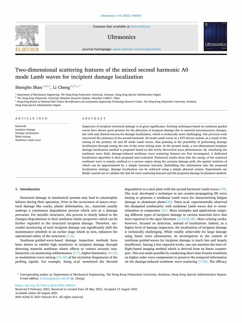
In a typical PZT-activated plate, both S0 and A0 mode Lamb waves can be simultaneously excited, as sketched in Fig. 1. When the plate exhibits nonlinear elasticity, even very weak, mutual interaction be-tween the primary A0 and S0 waves induces the generation of the 2nd A0 wave within a mixing zone as initially revealed in the 1D case[33]. Using tone burst excitations, the primary S0 and A0 waves both have a finite length in space, which entails firstly their mixing and then their separation because of the differences in their group velocities. A mixing zone boundary is defined when A0 and S0 waves completely separate. Therefore, mixed 2nd A0 waves are produced within a specific zone delimited by the mixing zone boundary. The size of the wave mixing zone is determined by the cycles of the tone burst excitation signals, which can be further tuned for damage localization.
Previous phase velocity analyses show that the 2nd A0 wave generated in a 2 mm-thick aluminum plate in the low-frequency range (under 500 kHz) does not produce rigorous cumulative effect [33]. It is well known the cumulative effect is beneficial for the measurement because the amplitude of the generated Lamb waves can be relatively large. However, even though the phase matching condition is not satisfied, the 2nd A0 wave can still be generated due to material nonlinearity although it is not cumulative. Therefore, any material changes can be characterized by this specific wave component. Having
Fig. 1. The 2nd A0 wave generation.
Fig. 2. Finite element model description and the linear wavefield at 0.08 ms.
S. Shan and L. Cheng
Ultrasonics 119 (2022) 106554
3
said that, it should be noted that this non-cumulative feature will in-fluence the size of the reachable inspection zone so that we need to ensure the generated nonlinear waves are clearly measurable in the tests.
FE simulations are conducted to confirm the aforementioned phe-nomenon in a 2D plate and to show the wave mixing characteristics. The model is built in Abaqus Explicit as shown in Fig. 2. A quarter-plate model is used with symmetric boundary conditions applied on the left and bottom edges to reduce the computational cost. The size of the quarter plate is 400 mm * 400 mm * 2 mm. The mesh size is 0.5 mm * 0.5 mm * 0.5 mm which ensures around 17 elements per smallest wavelength of interest (8.7 mm for the 2nd A0 wave). A pair of point forces is applied on the top and the bottom surfaces to excite both A0 and S0 mode Lamb waves in the plate. The excitation signal is a 5-cycle tone burst signal at 100 kHz. The material nonlinearity is introduced to the model according to the Landau-Lifshitz model via the VUMAT module [34]. The material parameters of the aluminum plate under different simulation scenarios are tabulated in Table 1. Linear Al (LAl) represents the ideal aluminum material without any nonlinear elasticity. Nonlinear Al (NAl) stands for the intact aluminum material with weak nonlinearity throughout the plate. Damaged Al (DAl) mimics the material with incipient damage, introduced through Landau constants, which are different from NAl within the damaged area [35]. It is worth noting that the Landau constants in DAl are chosen for the purpose of validating the proposed method, which do not necessarily correspond to a specific physical incipient damage. The exact relationship between a given incipient damage type and the corresponding changes in the Landau constants is beyond the scope of this paper, although this is an inter-esting topic which deserves future studies.
First, the LAl plate is used to check the primary wave propagating characteristics at the fundamental frequency of 100 kHz. The magnitude of the displacement field is plotted at 0.08 ms in Fig. 2 (without the two damages), showing both linear A0 and S0 mode Lamb waves. Through scrutinizing the wave propagation process in the FE model, a mixing-
zone boundary is identified as marked by a white ring in the figure, which coincides with the mixing zone predicted from theoretical calculations.
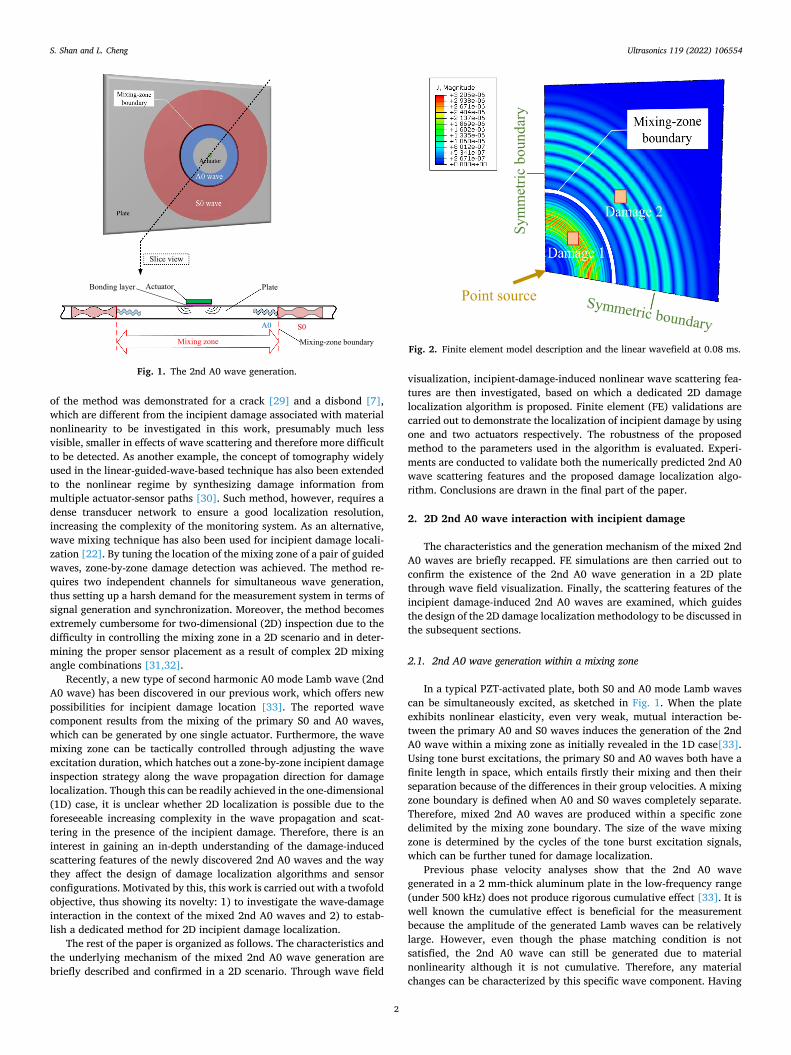
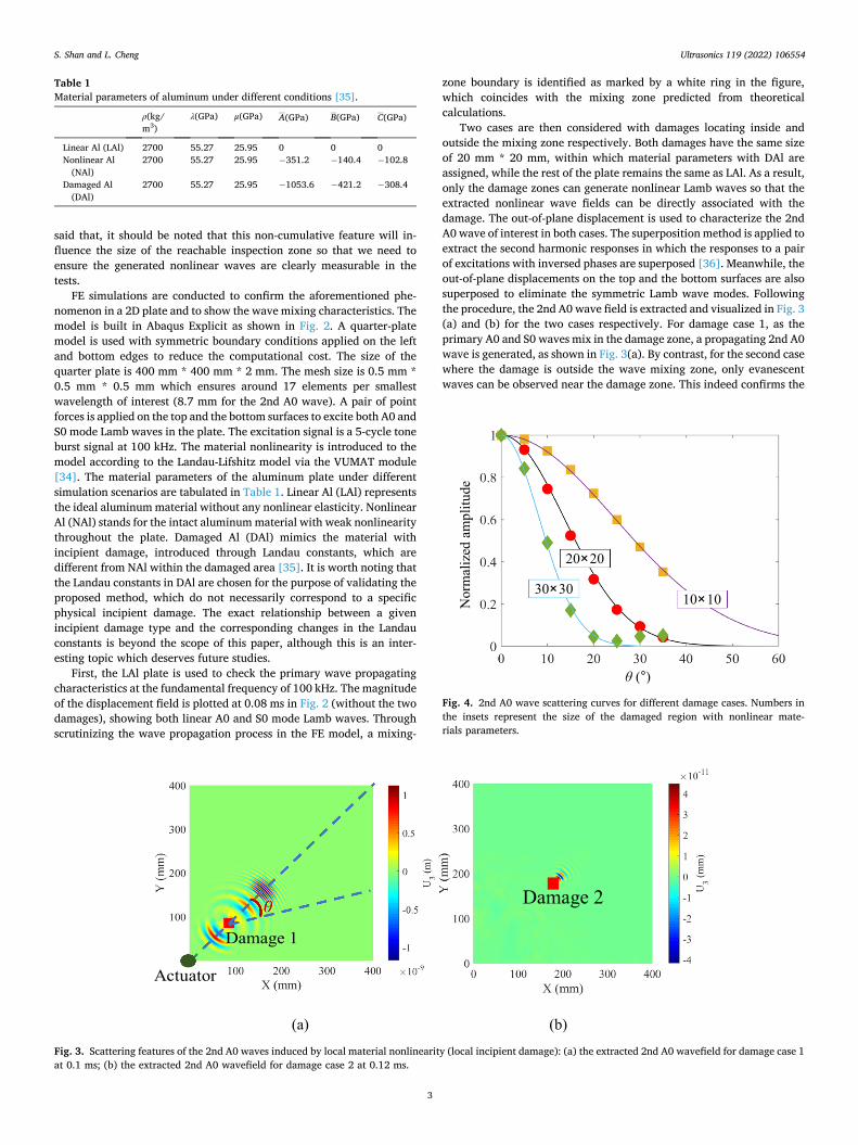
Two cases are then considered with damages locating inside and outside the mixing zone respectively. Both damages have the same size of 20 mm * 20 mm, within which material parameters with DAl are assigned, while the rest of the plate remains the same as LAl. As a result, only the damage zones can generate nonlinear Lamb waves so that the extracted nonlinear wave fields can be directly associated with the damage. The out-of-plane displacement is used to characterize the 2nd A0 wave of interest in both cases. The superposition method is applied to extract the second harmonic responses in which the responses to a pair of excitations with inversed phases are superposed [36]. Meanwhile, the out-of-plane displacements on the top and the bottom surfaces are also superposed to eliminate the symmetric Lamb wave modes. Following the procedure, the 2nd A0 wave field is extracted and visualized in Fig. 3 (a) and (b) for the two cases respectively. For damage case 1, as the primary A0 and S0 waves mix in the damage zone, a propagating 2nd A0 wave is generated, as shown in Fig. 3(a). By contrast, for the second case where the damage is outside the wave mixing zone, only evanescent waves can be observed near the damage zone. This indeed confirms the
Table 1 Material parameters of aluminum under different conditions [35].
ρ(kg/ m3)
λ(GPa) μ(GPa) A(GPa) B(GPa) C(GPa)
Linear Al (LAl) 2700 55.27 25.95 0 0 0 Nonlinear Al
(NAl) 2700 55.27 25.95 − 351.2 − 140.4 − 102.8
Damaged Al (DAl)
2700 55.27 25.95 − 1053.6 − 421.2 − 308.4
Fig. 3. Scattering features of the 2nd A0 waves induced by local material nonlinearity (local incipient damage): (a) the extracted 2nd A0 wavefield for damage case 1 at 0.1 ms; (b) the extracted 2nd A0 wavefield for damage case 2 at 0.12 ms.
Fig. 4. 2nd A0 wave scattering curves for different damage cases. Numbers in the insets represent the size of the damaged region with nonlinear mate-rials parameters.
S. Shan and L. Cheng
Ultrasonics 119 (2022) 106554
4
mixed 2nd A0 wave generation in the current 2D framework.
2.2. 2nd A0 wave scattering features due to local incipient damage
The mixed 2nd wave scattering features are then investigated using damage case 1 as shown in Fig. 3(a). The energy of the scattered nonlinear waves is found to be mainly confined to a narrow area along the actuator-damage path. For quantifications, a scattering angle θ is defined as illustrated in Fig. 3(a). By extracting the 2nd A0 wave amplitude at different points with the same distance to the damage center but different θ and carrying out the normalization with respect to the largest value, the nonlinear wave scattering pattern can be obtained and shown in Fig. 4 for three different damage sizes (the red dots cor-responds to the case of 20 mm * 20 mm). These tendency curves show a rapid attenuation of the 2nd A0 wave amplitude with respect to the increasing scattering angle θ, suggesting that the incipient damage mainly affects the 2nd A0 wave responses when it locates on the actuator-sensor path. A Gaussian function is used to fit the numerical data and a 2nd A0 wave scattering curve is obtained in Fig. 4 as
Wt(θ) = e−
(
θu
)2
(1)
where Wt(θ) is called the weighting function which will be used in the subsequent damage localization algorithm. It is worth noting the above expression only involves one parameter u, which determines the scat-tering pattern of the damage-induced nonlinear wave beam. In this specific case, this parameter is determined to equal 19.28 after curve fitting. The same procedure is repeated for the other two damage cases with different sizes (10 mm * 10 mm and 30 mm *30 mm). After extracting the normalized amplitude of the scattering nonlinear waves at different angles, the same Gaussian function as in Eq. (1) is applied to fit the numerical results. Although u obviously takes different values (32.44 and 11.17 for the smaller and larger damage cases respectively), the same Gaussian variation trend is still followed. All fitted scattering curves are plotted together in Fig. 4. It follows that, with the increase in the damage size, the scattered nonlinear waves become more central-ized. Most importantly, the nonlinear waves generated by different local incipient damage show the similar variation pattern which can be generally represented by a simple Gaussian function. From these simu-lations, it can be surmised that the shape of the damage would not fundamentally change this basic feature. This has also been confirmed with a circular damage zone in the simulation. It was observed that the Gaussian function can still be used to fit the scattering trend (not shown here). This feature will be fully explored in the damage localization applications to be discussed in the following sections.
3. 2D incipient damage localization
Based on the wave-damage interaction features observed above, a 2D incipient damage localization strategy is proposed and demonstrated through numerical examples. The principle of the proposed 2nd A0- wave-based 2D localization, alongside a dedicated algorithm, is first formulated. The proposed method is then validated and further evalu-ated through FE analyses.
3.1. Principle of 2D damage localization based on 2nd A0 waves
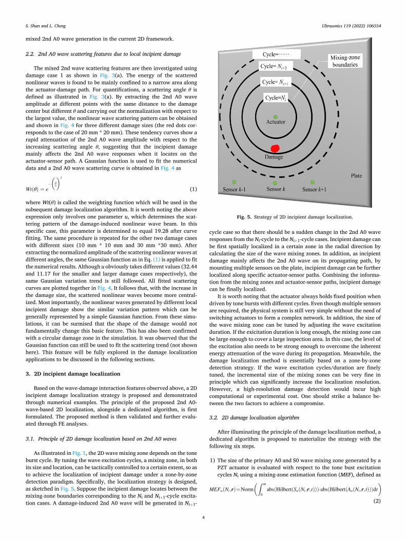
As illustrated in Fig. 1, the 2D wave mixing zone depends on the tone burst cycle. By tuning the wave excitation cycles, a mixing zone, in both its size and location, can be tactically controlled to a certain extent, so as to achieve the localization of incipient damage under a zone-by-zone detection paradigm. Specifically, the localization strategy is designed, as sketched in Fig. 5. Suppose the incipient damage locates between the mixing-zone boundaries corresponding to the Ni and Ni+1-cycle excita-tion cases. A damage-induced 2nd A0 wave will be generated in Ni+1-
cycle case so that there should be a sudden change in the 2nd A0 wave responses from the Ni-cycle to the Ni+1-cycle cases. Incipient damage can be first spatially localized in a certain zone in the radial direction by calculating the size of the wave mixing zones. In addition, as incipient damage mainly affects the 2nd A0 wave on its propagating path, by mounting multiple sensors on the plate, incipient damage can be further localized along specific actuator-sensor paths. Combining the informa-tion from the mixing zones and actuator-sensor paths, incipient damage can be finally localized.
It is worth noting that the actuator always holds fixed position when driven by tone bursts with different cycles. Even though multiple sensors are required, the physical system is still very simple without the need of switching actuators to form a complex network. In addition, the size of the wave mixing zone can be tuned by adjusting the wave excitation duration. If the exicitation duration is long enough, the mixing zone can be large enough to cover a large inspection area. In this case, the level of the excitation also needs to be strong enough to overcome the inherent energy attenuation of the wave during its propagation. Meanwhile, the damage localization method is essentially based on a zone-by-zone detection strategy. If the wave excitation cycles/duration are finely tuned, the incremental size of the mixing zones can be very fine in principle which can significantly increase the localization resolution. However, a high-resolution damage detection would incur high computational or experimental cost. One should strike a balance be-tween the two factors to achieve a compromise.
3.2. 2D damage localization algorithm
After illuminating the principle of the damage localization method, a dedicated algorithm is proposed to materialize the strategy with the following six steps.
1) The size of the primary A0 and S0 wave mixing zone generated by a PZT actuator is evaluated with respect to the tone bust excitation cycles Ni using a mixing-zone estimation function (MEF), defined as
MEFa(Ni,r)=Norm(∫ ∞
0abs(Hilbert(Sa(Ni,r,t)))⋅abs(Hilbert(Aa(Ni,r,t)))dt
)
(2)
Fig. 5. Strategy of 2D incipient damage localization.
S. Shan and L. Cheng
Ultrasonics 119 (2022) 106554
5
where Sa(Ni,r,t) and Aa(Ni,r,t) are respectively the time-domain re-sponses of the primary S0 and A0 mode Lamb waves at a certain position r away from the actuator. The subscript a denotes a specific PZT actu-ator. The responses are calculated using the previously developed theoretical model which takes into account the dispersion of Lamb waves [36,37]. The operations abs(Hilbert()) and Norm() denote the envelope of a signal obtained from the Hilbert transform and normali-zation of a signal with respect to its maximum value, respectively. Although the 2D wave divergence is not considered in the theoretical model, it does not affect the evaluation of MEF owing to the normali-zation operation.
2) A zone determination function (ZDF) is proposed using the MEF to define an effective zone for damage localization to avoid the effect of double-counted damage information from different excitation cycle cases [33]. The ZDF is defined as
ZDFa(Ni, r) =
⎧⎪⎨
⎪⎩
MEFa(N1, r) for i = 1
Norm(
MEFa(Ni, r)MEFa(Ni− 1, r)
− 1)
for i⩾2(3)
With the proposed ZDF, each excitation cycle case is responsible for a certain independent inspection zone with a likelihood distribution of damage localization.
3) A damage index is defined based on the measurement results for a given excitation cycle case as
DIa(Ni, s) =Atest(Ni, s)
Abaseline(Ni, s)(4)
where Atest and Abaseline are the 2nd A0 wave amplitudes for the specimen under inspection and baseline status respectively; s stands for the sensor index.
4) Based on the same principle as that in the definition of the ZDF, an effective damage index (EDI) is proposed accordingly as
EDIa(Ni, s) =
⎧⎪⎨
⎪⎩
(Max
(DIa,s
)− 1
)⋅|DIa(N1, s) − 1| for i = 1
(Max
(DIa,s
)− 1
)⋅⃒⃒⃒⃒
DIa(Ni, s)DIa(Ni− 1, s)
− 1⃒⃒⃒⃒ for i⩾2
(5)
In the equation, Max(DIa,s) stands for the maximum DI values for all the excitation cases with different cycles for a specific actuator a and specific sensor s. As the system is vulnerable to noises for low value of DIs, the term (Max(DIa,s)-1) can significantly reduce the noise influence in the evaluation of EDI.
5) A weighting function Wt(θr-s) is introduced to enrich the data in-formation so as to achieve the inspection of the 2D area with a finite number of actuator-sensor paths. More specifically, as illustrated in
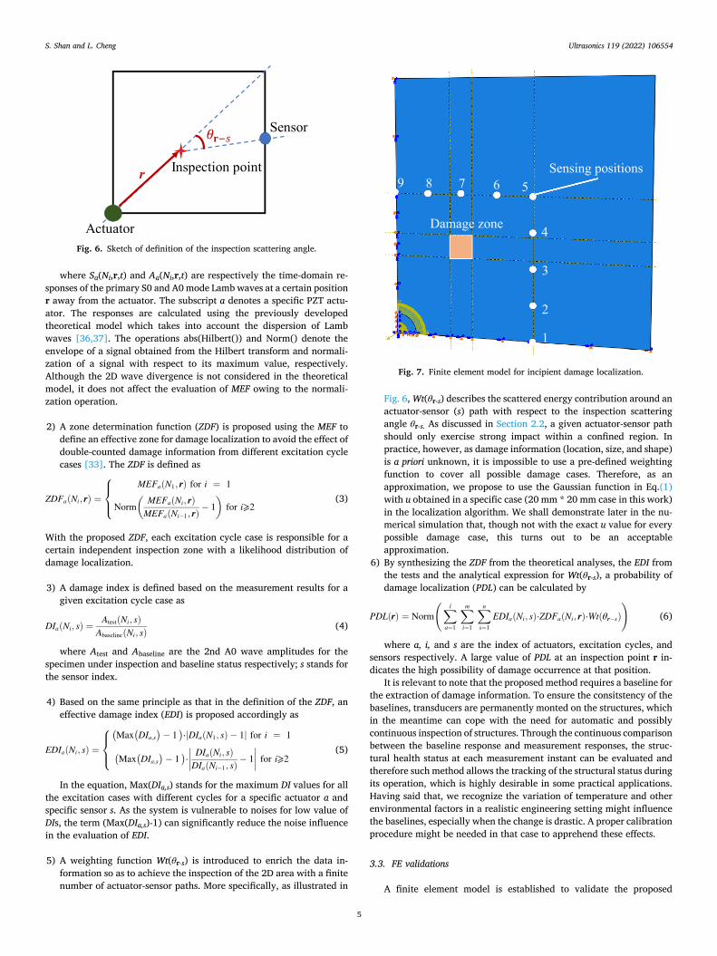
Fig. 6, Wt(θr-s) describes the scattered energy contribution around an actuator-sensor (s) path with respect to the inspection scattering angle θr-s. As discussed in Section 2.2, a given actuator-sensor path should only exercise strong impact within a confined region. In practice, however, as damage information (location, size, and shape) is a priori unknown, it is impossible to use a pre-defined weighting function to cover all possible damage cases. Therefore, as an approximation, we propose to use the Gaussian function in Eq.(1) with u obtained in a specific case (20 mm * 20 mm case in this work) in the localization algorithm. We shall demonstrate later in the nu-merical simulation that, though not with the exact u value for every possible damage case, this turns out to be an acceptable approximation.
6) By synthesizing the ZDF from the theoretical analyses, the EDI from the tests and the analytical expression for Wt(θr-s), a probability of damage localization (PDL) can be calculated by
PDL(r) = Norm
(∑l
a=1
∑m
i=1
∑n
s=1EDIa(Ni, s)⋅ZDFa(Ni, r)⋅Wt(θr− s)
)
(6)
where a, i, and s are the index of actuators, excitation cycles, and sensors respectively. A large value of PDL at an inspection point r in-dicates the high possibility of damage occurrence at that position.
It is relevant to note that the proposed method requires a baseline for the extraction of damage information. To ensure the consitstency of the baselines, transducers are permanently monted on the structures, which in the meantime can cope with the need for automatic and possibly continuous inspection of structures. Through the continuous comparison between the baseline response and measurement responses, the struc-tural health status at each measurement instant can be evaluated and therefore such method allows the tracking of the structural status during its operation, which is highly desirable in some practical applications. Having said that, we recognize the variation of temperature and other environmental factors in a realistic engineering setting might influence the baselines, especially when the change is drastic. A proper calibration procedure might be needed in that case to apprehend these effects.
3.3. FE validations
A finite element model is established to validate the proposed
Fig. 6. Sketch of definition of the inspection scattering angle.
Fig. 7. Finite element model for incipient damage localization.
S. Shan and L. Cheng
Ultrasonics 119 (2022) 106554
6
method, using a configuration illustrated in Fig. 7. The size of the plate is the same as the one used in the previous sections, also with symmetric boundary conditions applied on the left and the bottom edges. Both intact and damage cases are considered. In the former case, the plate is assigned with NAl parameters with weak nonlinearity. In the latter case, the location of the damage zone is arbitrarily chosen over the plate to verify the proposed method with the size of the incipient damage zone being 40 mm * 40 mm. The damage zone and the rest of the plate are assigned with DAl and NAl parameters, respectively. Different from the previous simulation, a PZT ring is used as the actuator. The traction loads on the boundaries of the ring are imposed to simulate the effect of the PZT actuation. The inner and outer radius of the ring is 10 mm and 26 mm respectively. Note again the cumulative effect is not necessary for the present damage detection cases so that the choice of the excita-tion frequency is flexible, which is set to 150 kHz in this case. In this specific configuration, the generated primary A0 and S0 waves have relatively close amplitudes. More importantly, the use of the ring-type excitation can significantly reduce the wave attenuation effect caused by the 2D wave divergence. Otherwise, the nonlinear responses captured by a sensor far away from the actuator would have been mainly from the material nonlinearity near the actuation region. As a result, any damage far away from the actuator on the actuator-sensor path can hardly be detected by the sensor. As to the sensors, as the location of damage is unknown prior to the inspection, nine sensing positions are used to form a square inspection area of 250 mm * 250 mm as shown in Fig. 7. It is
worth noting the choice of the sensor positions can be rather arbitrary and the inspection area can be of any shape in principle. he super-position method is used and the out-of-plane displacements of the sensing points on the top surface and their corresponding points on the bottom surfaces are superposed to extract the 2nd A0 wave signals.
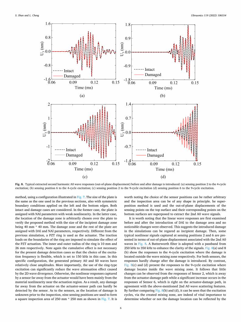
It is worth noting that the linear wave responses are first examined before and after the introduction of DAl to the damage area and no noticeable changes were observed. This suggests the introduced damage in the simulations can be regared as incipient damage. Then, some typical nonlinear signals captured at sensing positions 2 and 6 are pre-sented in terms of out-of-plane displacement associated with the 2nd A0 waves in Fig. 8. A Butterworth filter is adopted with a passband from 250 kHz to 350 kHz to enhance the clarity of the signals. Fig. 8(a) and 8 (b) show the responses to the 4-cycle excitation where the damage is located outside the wave mixing zone respectively. For both sensors, the responses hardly change after the damage is introduced. By contrast, Fig. 8(c) and (d) present the responses to the 9-cycle excitation where damage locates inside the wave mixing zone. It follows that little changes can be observed from the responses of Sensor 2, which is away from the actuator-damage path while a significant increase occurs in the responses of Sensor 6, which is right on the actuator-damage path, in agreement with the above-mentioned 2nd A0 wave scattering features. By further comparing Fig. 8(b) and (d), it can be seen that the excitation cycles, via the created mixing zone, are indeed of vital importance to determine whether or not the damage location can be reflected by the
Fig. 8. Typical extracted second harmonic A0 wave responses (out-of-plane displacement) before and after damage is introduced: (a) sensing position 2 to the 4-cycle excitation; (b) sensing position 6 to the 4-cycle excitation; (c) sensing position 2 to the 9-cycle excitation (d) sensing position 6 to the 9-cycle excitation.
S. Shan and L. Cheng
Ultrasonics 119 (2022) 106554
7
capture sensor responses, which can subsequently be used for damage localization.
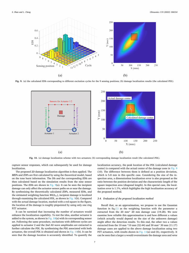
The proposed 2D damage localization algorithm is then applied. The MEFs and ZDFs are first calculated by using the theoretical model, based on the tone burst information. The DIs and the corresponding EDIs are then calculated based on the simulation results from the nine sensor positions. The EDIs are shown in Fig. 9(a). It can be seen the incipient damage can only affect the actuator-sensor paths on or near the damage. By synthesizing the theoretically calculated ZDFs, measured EDIs, and the estimated weighting function Wt(θr-s), incipient damage is localized through examining the calculated PDL, as shown in Fig. 9(b). Compared with the actual damage location, marked with a red square in the figure, the location of the damage is roughly pinpointed by using only one ring PZT actuator.
It can be surmised that increasing the number of actuators would enhance the localization capability. To test the idea, another actuator is added to the system, as shown in Fig. 10(a) with its corresponding sensor set. Following the same procedure, excitations with different cycles are applied to actuator 2 and the 2nd A0 wave amplitudes are extracted to further calculate the PDL. By synthesizing the PDL associated with both actuators, the overall PDL is obtained and shown in Fig. 10(b). It can be seen that the damage location is accurately identified. To quantify the
localization accuracy, the peak location of the PDL (calculated damage center) is compared with the actual center of the damage zone in Fig. 9 (10). The difference between them is defined as a position deviation, which is 5.8 mm in this specific case. Considering the size of the in-spection area, a dimensionless localization error is also proposed as the ratio between the position deviation and the characteristic length of the square inspection area (diagonal length). In this special case, the local-ization error is 1.1%, which highlights the high localization accuracy of the proposed method.
3.4. Evaluation of the proposed localization method
Recall that, as an approximation, we propose to use the Gaussian function in Eq.(1) as the weighting function with the parameter u extracted from the 20 mm* 20 mm damage case (19.28). We now examine how reliable this approximation is and how different u values (which actually would depend on the size of the unknown damage) might affect the detection results. To this end, the other two u values extracted from the 10 mm *10 mm (32.44) and 30 mm* 30 mm (11.17) damage cases are applied to the above damage localization using two PZT actuators, with results shown in Fig. 11(a) and (b), respectively. It can be seen that a larger u would overestimate the damage area and verse
Fig. 9. (a) the calculated EDIs corresponding to different excitation cycles for the 9 sensing positions; (b) damage localization results (the calculated PDL).
Fig. 10. (a) damage localization scheme with two actuators; (b) corresponding damage localization result (the calculated PDL).
S. Shan and L. Cheng
Ultrasonics 119 (2022) 106554
8
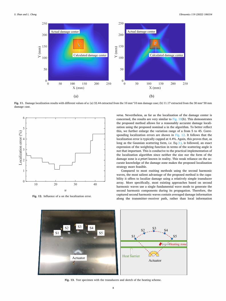
versa. Nevertheless, as far as the localization of the damage center is concerned, the results are very similar to Fig. 10(b). This demonstrates the proposed method allows for a reasonably accurate damage locali-zation using the proposed nominal u in the algorithm. To better reflect this, we further enlarge the variation range of u from 5 to 45. Corre-sponding localization errors are shown in Fig. 12. It follows that the localization error is typically capped at 4.4%. Again, this proves that, as long as the Gaussian scattering form, i.e. Eq.(1), is followed, an exact expression of the weighting function in terms of the scattering angle is not that important. This is conducive to the practical implementation of the localization algorithm since neither the size nor the form of the damage zone is a priori known in reality. This weak reliance on the ac-curate knowledge of the damage zone makes the proposed localization strategy more feasible.
Compared to most exsiting methods using the second harmonic waves, the most salient advantage of the proposed method is the capa-bility it offers to localize damage using a relatively simple transducer array. More specifically, most existing approaches based on second harmonic waves use a single fundamental wave mode to generate the second harmonic components during its propagation. Therefore, the captured second harmonic waves contain averaged damage information along the transmitter–receiver path, rather than local information
Fig. 11. Damage localization results with different values of u: (a) 32.44 extracted from the 10 mm*10 mm damage case; (b) 11.17 extracted from the 30 mm*30 mm damage case.
Fig. 12. Influence of u on the localization error.
Fig. 13. Test specimen with the transducers and sketch of the heating scheme.
S. Shan and L. Cheng
Ultrasonics 119 (2022) 106554
9
arising from localized incipient damage. Therefore, to achieve damage localization, multiple transmitter–receiver paths have to be used, which usually requires a complex transducer array. By comparison, in the proposed method based on the primary A0 and S0 mixing, through tuning the wave excitation cycles to control the wave mixing zone size, damage detection can be carried out zone-by-zone to further realize damage localization on the transmitter–receiver path. Taking advantage of this feature, incipient damage localization can be realized with a simple physical system with very few actuators.
4. Experimental validations
Finally, experiments are carried out to validate both the numerically revealed 2nd A0 wave scattering features and the proposed damage localization algorithm. A half-ring PZT actuator and five square PZT sensors are bonded on a 2024-T3 aluminum plate (625 mm * 625 mm *2 mm), as shown in Fig. 13. The inner and outer radius of the actuator is 14 mm and 30 mm respectively. The half-ring PZT actuator is specially designed for several reasons. 1). It guarantees the effective generation and propagation of Lamb waves towards the inspection region; 2) the width of the ring is carefully designed to ensure that primary A0 and S0 waves are strongly excited at 150 kHz according to the frequency tuning curves to ensure the effective generation of the 2nd A0 wave; 3). It en-sures weak attenuation of the wave amplitude due to the 2D wave beam divergence compared with a traditional circular PZT disc; 4). The in-fluence of the adhesive nonlinearity can be mitigated at this frequency based on our previous works [36,37]. Specifically, the excitation fre-quency is selected near the valley of the frequency tuning curve of the adhesive-nonlinearity-induced 2nd A0 wave associated with the 16 mm- wide PZT. Five small sensors (5 mm * 5 mm * 0.3 mm), denoted by S1, S2, S3, S4, and S5 respectively in Fig. 13, are bonded on the plate. The distances between the actuator and sensors are 200 mm, covering a quarter-circular inspection area marked in Fig. 13.
A thermal treatment is applied to create an incipient damage in the plate. The effectiveness of the technique as well as the corresponding material changes has been investigated in both literature [15] and our previous works [33,37,38]. More specific to the present case, an aluminum block of 40 mm * 20 mm*5 mm is placed along the Actuator- S4 path as illustrated in Fig 0.12 to conduct heat from a heating platform
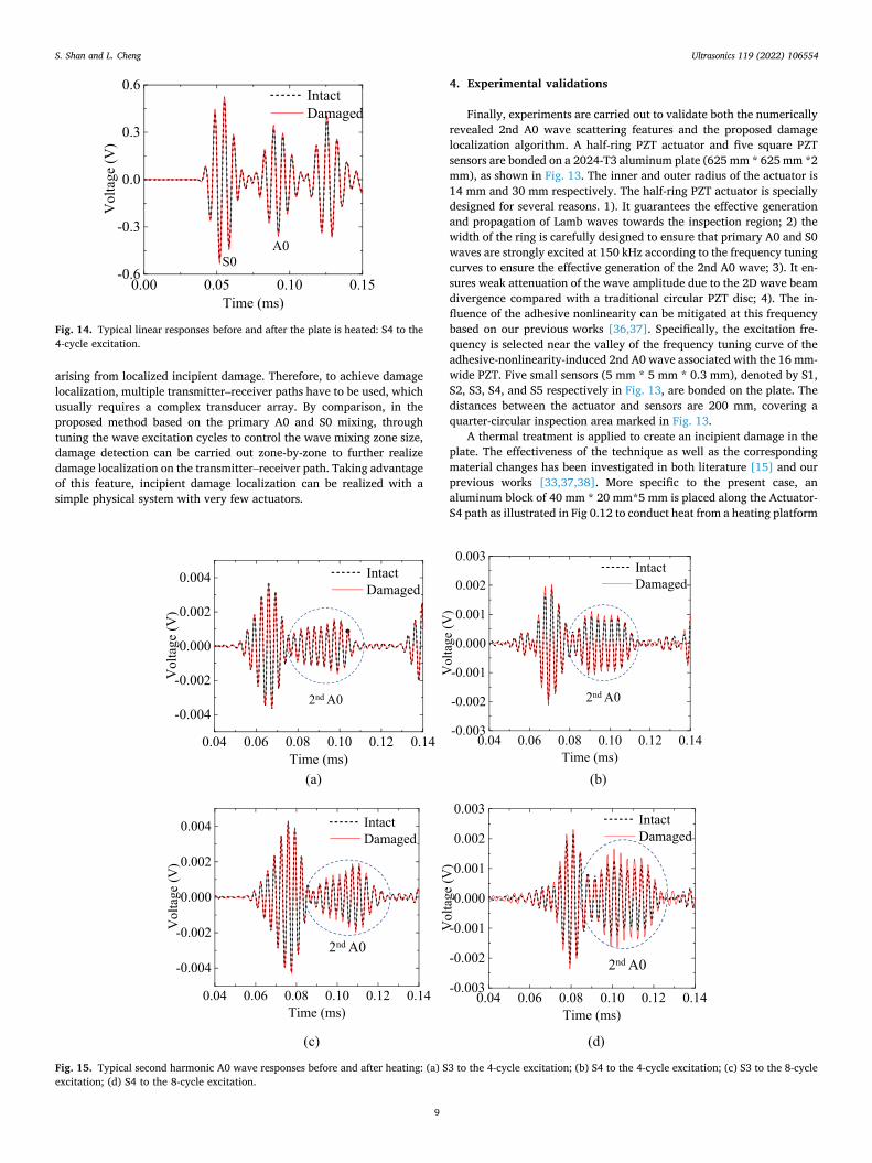
Fig. 14. Typical linear responses before and after the plate is heated: S4 to the 4-cycle excitation.
Fig. 15. Typical second harmonic A0 wave responses before and after heating: (a) S3 to the 4-cycle excitation; (b) S4 to the 4-cycle excitation; (c) S3 to the 8-cycle excitation; (d) S4 to the 8-cycle excitation.
S. Shan and L. Cheng
Ultrasonics 119 (2022) 106554
10
to the plate. The heating platform is set to 400 ◦C and maintained for 4 h. In addition, similar to the previous work [33], heat barriers with the flowing water are installed to prevent the heat transfer from the heating zone to the transducers. Due to the high thermal conductivity of aluminum, heat spreads fast from the heating zone to the flowing cooling water, thus limiting the high-temperature area mainly within the zone under the aluminum block (more than 300 ◦C by measure-ment). The temperature decreases very quickly outside the heating zone. As a result, the local incipient damage zone cerated by thermal treat-ment should be slightly larger than the heating zone in principle. Having said that, it is extremely difficult to quantify the precise size of the local damage zone so that the heating zone is reasonably assumed to be the incipient damage zone in the subsequent discussions.
Measurements are carried out before and after the heating by using different wave excitation cycles (3 to 10 stepped by 1). The amplitude of the excitation voltage on the PZT in all cases is 160 V. Meanwhile, a pair of excitations with inverse phases are used in the superposition method for the second harmonic extraction. The equipment and the corre-sponding measurement procedures are identical to those detailed in our previous work [36].
First, the linear responses are examined before and after the plate is heated. A pair of typical signals are shown in Fig. 14 as the responses of S4 to a 4-cycle excitation. It can be seen that linear responses hardly change after heating even though the heating zone is on the Actuator-S4 path. By scrutinizing all the linear responses of different sensors to different excitation cycles, it is observed that all linear wave signals remain almost unaffected after the plate is heated. This proves that
linear guided waves are not sensitive to such small microstructural changes.
The second harmonic responses are then extracted with the super-position method. In addition, a Butterworth filter is adopted with a passband from 250 kHz to 350 kHz to further enhance the clarity of the signals. Some typical responses of S3 and S4 which locate near and on the actuator-damage path respectively are presented in Fig. 15. Specif-ically, Fig. 15(a) and (b) show their responses to the 4-cycle excitation where the wave mixing zone does not cover the heating zone. For this 4- cycle excitation case, both sensor responses show no visible change after the heating. By contrast, when the 8-cycle excitation is deployed where damage locates inside the wave mixing zone, while little changes can be observed from the responses of S3 in Fig. 15(c), a significant increase (33%) occurs in the responses of S4 in Fig. 15(d). This clearly confirms that such heating-induced incipient damage mainly affects the waves on the actuator-damage path. In addition, by comparing Fig. 15(b) and (d), the dependence of the 2nd A0 wave change on the wave excitation cy-cles is also evident, consistent with the numerical predictions.
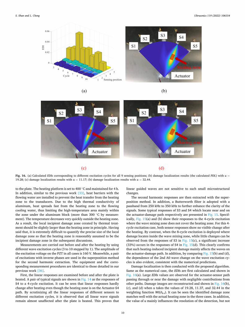
Damage localization is then conducted with the proposed algorithm. Same as the numerical case, the EDIs are first calculated and shown in Fig. 16(a). Large EDIs values are observed for the actuator-sensor path passing through or near the damage with negligible contributions from other paths. Damage images are reconstructed and shown in Fig. 16(b), (c), and (d) when u takes the values of 19.28, 11.37, and 32.44 in the weighting function Wt(θr-s). It can be seen the identified damage zone matches well with the actual heating zone in the three cases. In addition, the value of u mainly influences the resolution of the detection, but not
Fig. 16. (a) Calculated EDIs corresponding to different excitation cycles for all 9 sensing positions; (b) damage localization results (the calculated PDL) with u =19.28; (c) damage localization results with u = 11.17; (b) damage localization results with u = 32.44.
S. Shan and L. Cheng
Ultrasonics 119 (2022) 106554
11
the location of the damage, which is consistent with observations made from numerical simulations.
In conclusion, experiments clearly confirm the numerically predicted 2nd A0 wave scattering features and demonstrate the feasibility of the proposed damage localization algorithm. It is also relavent to note the reported measurements were carried out in the laboratory environment where the variation of temperature was not considered to be an important issue. We repeated the tests a few times and the results were consistent.
5. Conclusions
A 2D incipient damage localization method is proposed using the mode-mixing-induced 2nd A0 waves. The mixed 2nd A0 wave genera-tion is confirmed in the 2D scenario and the nonlinear wave-incipient damage interaction in terms of wave scattering is investigated. Based on the scattering features of the 2nd A0 waves, a 2D damage localization algorithm is proposed by tuning wave mixing zones and multiple actuator-sensor paths. The efficacy of the localization method is demonstrated through FE simulations using one and two actuators respectively and the localization accuracy of the proposed method is evaluated. The numerically predicted damage-induced scattering fea-tures and the proposed localization algorithm are finally validated through experiments.
It is found that incipient damage related to material nonlinearly does not generate strong and omnidirectional scattering of the 2nd A0 waves, but rather within a confined region along the actuator-damage path. The scattering pattern with respect to angles roughly follows a Gaussian function, which can be reasonably approximated by a simple mathe-matical expression. Taking this feature into account, a relatively simple yet robust 2D incipient damage localization algorithm is established. Different from other existing methods, the proposed localization meth-odology only requires a simple physical system with a small number of actuators to achieve high-resolution damage localization through a proper tuning of the incremental size in the tune burst signals.
The presented method offers a brand new idea for incipient damage localization alongside the fundamental understandings on the nonlinear wave scattering features associated with material-degradation-related damage, which shows great promise for further investigations and practical SHM applications. Having said that, future efforts are still needed to consider various environment factors and their influence before practical engineering implementations. Possible establishment of the quantatitive realshionship between the nonlinear wave variation and the type and severity of a given damage would also require further studies in conjunction with material characterization testing and me-chanics analyses.
Declaration of Competing Interest
The authors declare that they have no known competing financial interests or personal relationships that could have appeared to influence the work reported in this paper.
Acknowledgments
The project was supported by grants from the Research Grants Council of Hong Kong Special Administrative Region (PolyU 152070/ 16E), the National Natural Science Foundations of China through SHENG project (Polish-Chinese Funding Initiative, 51961135302), Research Fund of State Key Laboratory of Mechanics and Control of Mechanical Structures (Nanjing University of Aeronautics and Astro-nautics, China. Grant No. MCMS-E-0520K01) and the Innovation and Technology Commission of the HKSAR Government to the Hong Kong Branch of National Rail Transit Electrification and Automation Engi-neering Technology Research Center.
References
[1] V.K. Chillara, C.J. Lissenden, Review of nonlinear ultrasonic guided wave nondestructive evaluation: theory, numerics, and experiments, Opt. Eng. 55 (2015), 011002.
[2] K.H. Matlack, J.-Y. Kim, L.J. Jacobs, J. Qu, Review of second harmonic generation measurement techniques for material state determination in metals, J. Nondestr. Eval. 34 (2015) 273.
[3] K.-Y. Jhang, Nonlinear ultrasonic techniques for nondestructive assessment of micro damage in material: a review, Int. J. Precis. Eng. Manuf. 10 (2009) 123–135.
[4] C. Lissenden, Y. Liu, J.L. Rose, Use of non-linear ultrasonic guided waves for early damage detection, Insight-Non-Destructive Testing and Condition Monitoring, 57 (2015) 206-211.
[5] D. Ginzburg, F. Ciampa, G. Scarselli, M. Meo, SHM of single lap adhesive joints using subharmonic frequencies, Smart Mater. Struct. 26 (2017), 105018.
[6] S. Carrino, F. Nicassio, G. Scarselli, Subharmonics and beating: A new approach to Local Defect Resonance for bonded single lap joints, J. Sound Vib. 456 (2019) 289–305.
[7] F. Nicassio, S. Carrino, G. Scarselli, Non-linear Lamb Waves for Locating Defects in Single-Lap Joints, Front. Built Environ. 6 (2020) 45.
[8] N. Matsuda, S. Biwa, Phase and group velocity matching for cumulative harmonic generation in Lamb waves, J. Appl. Phys. 109 (2011), 094903.
[9] M. Deng, Cumulative second-harmonic generation of Lamb-mode propagation in a solid plate, J. Appl. Phys. 85 (1999) 3051–3058.
[10] F. Masurkar, P. Tse, N.P. Yelve, Evaluation of inherent and dislocation induced material nonlinearity in metallic plates using Lamb waves, Appl. Acoust. 136 (2018) 76–85.
[11] P. Zuo, Y. Zhou, Z. Fan, Numerical and experimental investigation of nonlinear ultrasonic Lamb waves at low frequency, Appl. Phys. Lett. 109 (2016), 021902.
[12] C. Bermes, J.-Y. Kim, J. Qu, L.J. Jacobs, Nonlinear Lamb waves for the detection of material nonlinearity, Mech. Syst. Sig. Process. 22 (2008) 638–646.
[13] W. Li, B. Chen, Y. Cho, Nonlinear feature of phase matched Lamb waves in solid plate, Appl. Acoust. 160 (2020), 107124.
[14] Y. Ishii, S. Biwa, T. Adachi, Non-collinear interaction of guided elastic waves in an isotropic plate, J. Sound Vib. 419 (2018) 390–404.
[15] M. Hasanian, C.J. Lissenden, Second order harmonic guided wave mutual interactions in plate: Vector analysis, numerical simulation, and experimental results, J. Appl. Phys. 122 (2017), 084901.
[16] V. Krishna Chillara, C.J. Lissenden, Interaction of guided wave modes in isotropic weakly nonlinear elastic plates: Higher harmonic generation, J. Appl. Phys. 111 (2012), 124909.
[17] S. Shan, M. Hasanian, H. Cho, C.J. Lissenden, L. Cheng, New nonlinear ultrasonic method for material characterization: Codirectional shear horizontal guided wave mixing in plate, Ultrasonics 96 (2019) 64–74.
[18] S.E. Lee, H.J. Lim, S. Jin, H. Sohn, J.-W. Hong, Micro-crack detection with nonlinear wave modulation technique and its application to loaded cracks, NDT and E Int. 107 (2019), 102132.
[19] Y. Xiang, M. Deng, F.-Z. Xuan, C.-J. Liu, Experimental study of thermal degradation in ferritic Cr–Ni alloy steel plates using nonlinear Lamb waves, NDT and E Int. 44 (2011) 768–774.
[20] H. Cho, M. Hasanian, S. Shan, C.J. Lissenden, Nonlinear guided wave technique for localized damage detection in plates with surface-bonded sensors to receive Lamb waves generated by shear-horizontal wave mixing, NDT and E Int. 102 (2019) 35–46.
[21] S. Patra, H. Ahmed, M. Saadatzi, S. Banerjee, Evidence of dissipative and growing nonlinearity in Lamb waves due to stress-relaxation and material degradation in composites, Ultrasonics 96 (2019) 224–231.
[22] H. Chen, G. Gao, N. Hu, M. Deng, Y. Xiang, Modeling and simulation of frequency mixing response of two counter-propagating Lamb waves in a two-layered plate, Ultrasonics, DOI (2020) 106109.
[23] C. Pruell, J.-Y. Kim, J. Qu, L.J. Jacobs, Evaluation of plasticity driven material damage using Lamb waves, Appl. Phys. Lett. 91 (2007), 231911.
[24] C. Pruell, J.-Y. Kim, J. Qu, L.J. Jacobs, Evaluation of fatigue damage using nonlinear guided waves, Smart Mater. Struct. 18 (2009), 035003.
[25] Y. Xiang, M. Deng, F.-Z. Xuan, Creep damage characterization using nonlinear ultrasonic guided wave method: A mesoscale model, J. Appl. Phys. 115 (2014), 044914.
[26] V. Marcantonio, D. Monarca, A. Colantoni, M. Cecchini, Ultrasonic waves for materials evaluation in fatigue, thermal and corrosion damage: A review, Mech. Syst. Sig. Process. 120 (2019) 32–42.
[27] P. Tse, F. Masurkar, N.P. Yelve, Estimation of remaining useful life of fatigued plate specimens using Lamb wave-based nonlinearity parameters, Struct. Control Health Monitoring 27 (2020), e2486.
[28] C.J. Lissenden, Nonlinear ultrasonic guided waves—Principles for nondestructive evaluation, J. Appl. Phys. 129 (2021), 021101.
[29] M. Hong, Z. Su, Y. Lu, H. Sohn, X. Qing, Locating fatigue damage using temporal signal features of nonlinear Lamb waves, Mech. Syst. Sig. Process. 60 (2015) 182–197.
[30] S. Boccardi, D.B. Calla, F. Ciampa, M. Meo, Nonlinear elastic multi-path reciprocal method for damage localisation in composite materials, Ultrasonics 82 (2018) 239–245.
[31] M. Hasanian, C.J. Lissenden, Second order ultrasonic guided wave mutual interactions in plate: Arbitrary angles, internal resonance, and finite interaction region, J. Appl. Phys. 124 (2018), 164904.
[32] M. Aslam, P. Nagarajan, M. Remanan, Defect localization using nonlinear Lamb wave mixing technique, J. Nondestr. Eval. 40 (2021) 1–12.
S. Shan and L. Cheng

Ultrasonics 119 (2022) 106554
12
[33] S. Shan, L. Cheng, Mode-mixing-induced second harmonic A0 mode Lamb wave for local incipient damage inspection, Smart Mater. Struct. 29 (2020), 055020.
[34] S. Shan, L. Cheng, Mixed third harmonic shear horizontal wave generation: interaction between primary shear horizontal wave and second harmonic Lamb wave, Smart Mater. Struct. 28 (2019), 085042.
[35] G. Choi, Y. Liu, X. Yao, C.J. Lissenden, Effect of localized microstructural evolution on higher harmonic generation of guided wave modes, AIP Conf. Proc., American Instit. Phys. (2015) 1592–1598.
[36] S. Shan, L. Cheng, P. Li, Adhesive nonlinearity in Lamb-wave-based structural health monitoring systems, Smart Mater. Struct. 26 (2016), 025019.
[37] S. Shan, L. Cheng, F. Wen, Design of nonlinear-Lamb-wave-based structural health monitoring systems with mitigated adhesive nonlinearity, Smart Mater. Struct. 27 (2018), 105006.
[38] F. Wen, S. Shan, L. Cheng, Third harmonic shear horizontal waves for material degradation monitoring, Struct. Health Monitoring, DOI (2020), 147592172093698.
S. Shan and L. Cheng