Embed Size (px)
DESCRIPTION
A powerpoint presentation on two port networks
Citation preview

TWO-PORT NETWORKS
In many situations one is not interested in the internal organization of anetwork. A description relating input and output variables may be sufficient
A two-port model is a description of a network that relates voltages and currentsat two pairs of terminals
Admittance parametersImpedance parametersHybrid parametersTransmission parameters
LEARNING GOALS
Study the basic types of two-port models
Understand how to convert one model into another
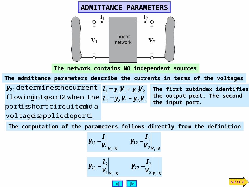
ADMITTANCE PARAMETERS
The admittance parameters describe the currents in terms of the voltages
2221212
2121111
VyVyI
VyVyI
The first subindex identifies
the output port. The secondthe input port.
1 port to applied is voltage
a and circuited-short is port
the when 2 port into flowing
current the determines 21y
The computation of the parameters follows directly from the definition
02
112
01
111
12
VV
V
Iy
V
Iy
02
222
01
221
12
VV
V
Iy
V
Iy
The network contains NO independent sources
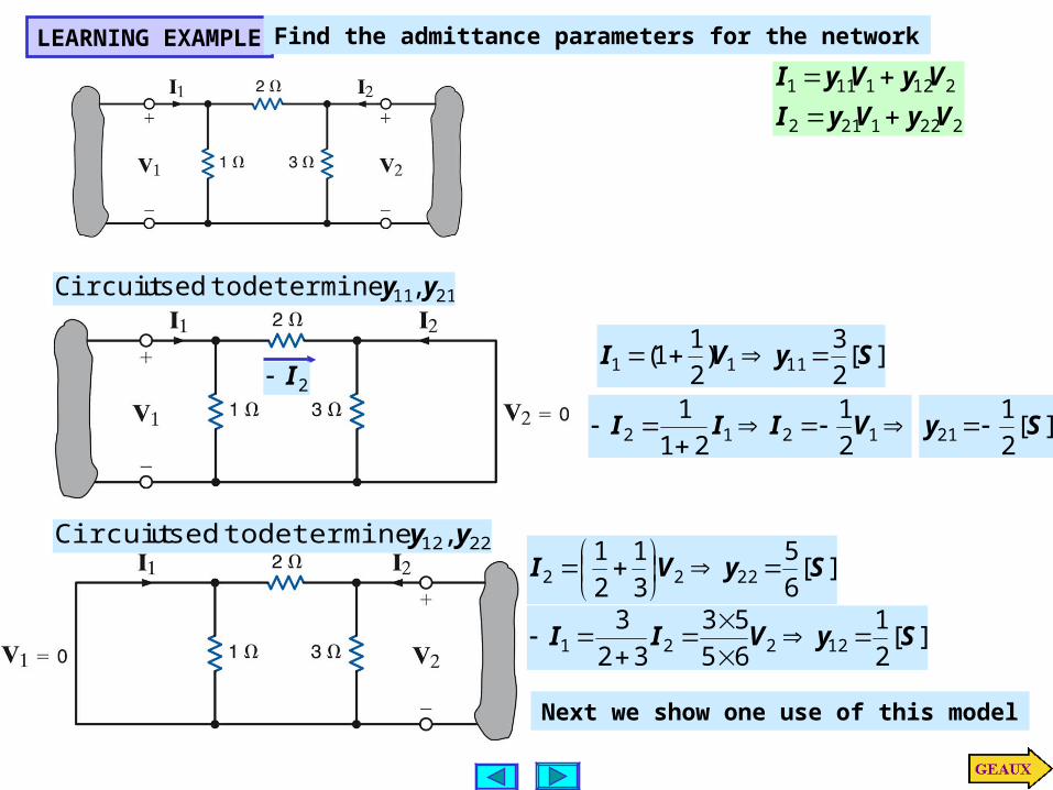
LEARNING EXAMPLEFind the admittance parameters for the network
2221212
2121111
VyVyI
VyVyI
][2
3)
2
11( 1111 SyVI
2111, yy determine to used Circuit
2I
1212 2
1
21
1VIII ][
2
121 Sy
2212 , yy determine to used Circuit][
6
5
3
1
2
12222 SyVI
][2
1
65
53
32
312221 SyVII
Next we show one use of this model

An application of the admittance parameters
2221212
2121111
VyVyI
VyVyI
212
211
6
5
2
12
1
2
3
VVI
VVI
221 4,2 IVAI
The model plus the conditions at theports are sufficient to determine theother variables.
21
21
4
1
6
5
2
10
2
1
2
32
VV
VV
22 4
1VI
][11
2
][11
86
13
2
2
21
AI
VV
VV
Determine the current through the4 Ohm resistor

IMPEDANCE PARAMETERS
The network contains NO independent sources
2221212
2121111
IzIzV
IzIzV
The ‘z parameters’ can be derived in a manner similar to the Y parameters
01
221
01
111
22
II
I
Vz
I
Vz
02
222
02
112
11
II
I
Vz
I
Vz
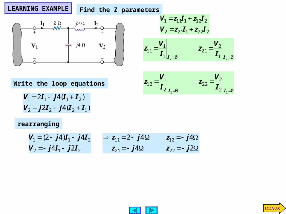
LEARNING EXAMPLE Find the Z parameters
Write the loop equations
)(42
)(42
1222
2111
IIjIjV
IIjIV
24
442
2221
1211
jzjz
jzjz
212
211
24
4)42(
IjIjV
IjIjV
rearranging
01
221
01
111
22
II
I
Vz
I
Vz
02
222
02
112
11
II
I
Vz
I
Vz
2221212
2121111
IzIzV
IzIzV

LEARNING EXAMPLEUse the Z parameters to find the current through the 4 Ohmresistor
2221212
2121111
IzIzV
IzIzV
Output port constraint
22 4IV
Input port constraint
11 )1(012 IV
212
211
24
4)42(
IjIjV
IjIjV
21 )24(40 IjIj
21 4)43(12 IjIj
)43( j4j
2))43)(24(16(48 Ijjj 73.13761.12I
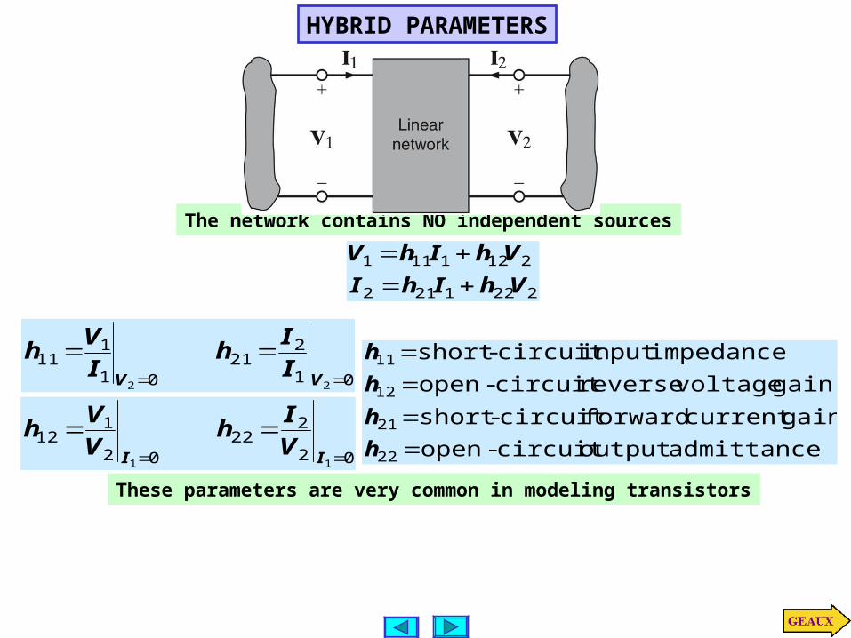
HYBRID PARAMETERS
The network contains NO independent sources
2221212
2121111
VhIhI
VhIhV
admittance output circuit-open
gain current forward circuit-short
gain voltage reverse circuit-open
impedance input circuit-short
22
21
12
11
h
h
h
h
These parameters are very common in modeling transistors
01
221
01
111
22
VV
I
Ih
I
Vh
02
222
02
112
11
II
V
Ih
V
Vh
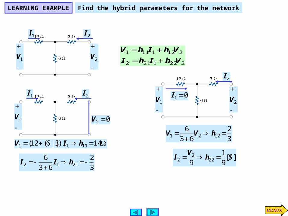
LEARNING EXAMPLE Find the hybrid parameters for the network
1I
1V
2I
2V2221212
2121111
VhIhI
VhIhV
1I
1V
2I
02 V
14))3||6(12( 1111 hIV
3
2
63
62112
hII
1V
2I
2V01 I
3
2
63
61221
hVV
][9
1
9 222
2 ShV
I
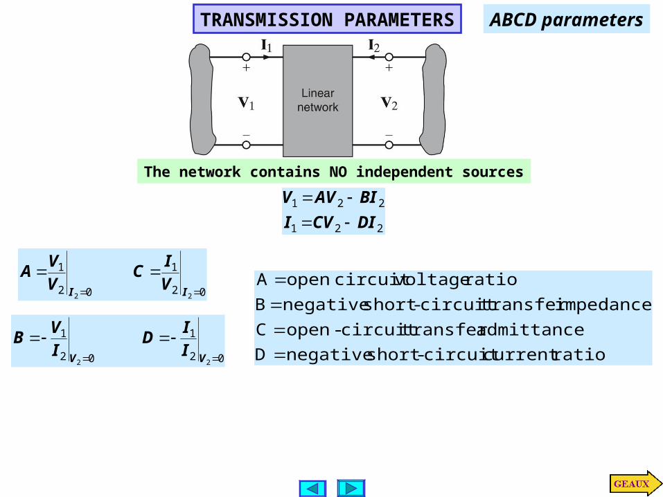
TRANSMISSION PARAMETERS
The network contains NO independent sources
221
221
DICVI
BIAVV
02
1
02
1
22
II
V
IC
V
VA
02
1
02
1
22
VV
I
ID
I
VB
ratio current circuit-short negative D
admittance transfer circuit-open C
impedance transfer circuit-short negative B
ratio voltage circuit openA
ABCD parameters
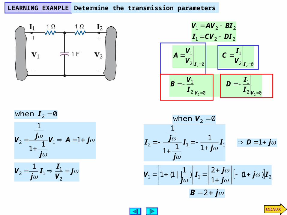
LEARNING EXAMPLEDetermine the transmission parameters
221
221
DICVI
BIAVV
02
1
02
1
22
II
V
IC
V
VA
02
1
02
1
22
VV
I
ID
I
VB
jAV
j
jV
1
11
1
12
jV
II
jV
2
112
1
02 I when02 V when
112 1
11
1
1
Ij
I
j
jI
jD 1
211 )1(1
2)
1||1(1 Ij
j
jI
jV
jB 2

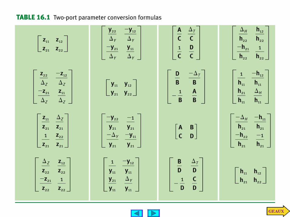
PARAMETER CONVERSIONS
If all parameters exist, they can be related by conventional algebraic manipulations.As an example consider the relationship between Z and Y parameters
2
11
2221
1211
2
1
2
1
2221
1211
2
1
2221212
2121111
V
V
zz
zz
I
I
I
I
zz
zz
V
V
IzIzV
IzIzV
2
1
2221
1211
V
V
yy
yy
1
2221
1211
2221
1211
zz
zz
yy
yy
1121
12221zz
zz
Z
12212211 zzzzZ with
In the following conversion table, the symbol stands for the determinant of the
corresponding matrix
DC
BA
hh
hh
yy
yy
zz
zzTHYZ ,,,
2221
1211
2221
1211
2221
1211
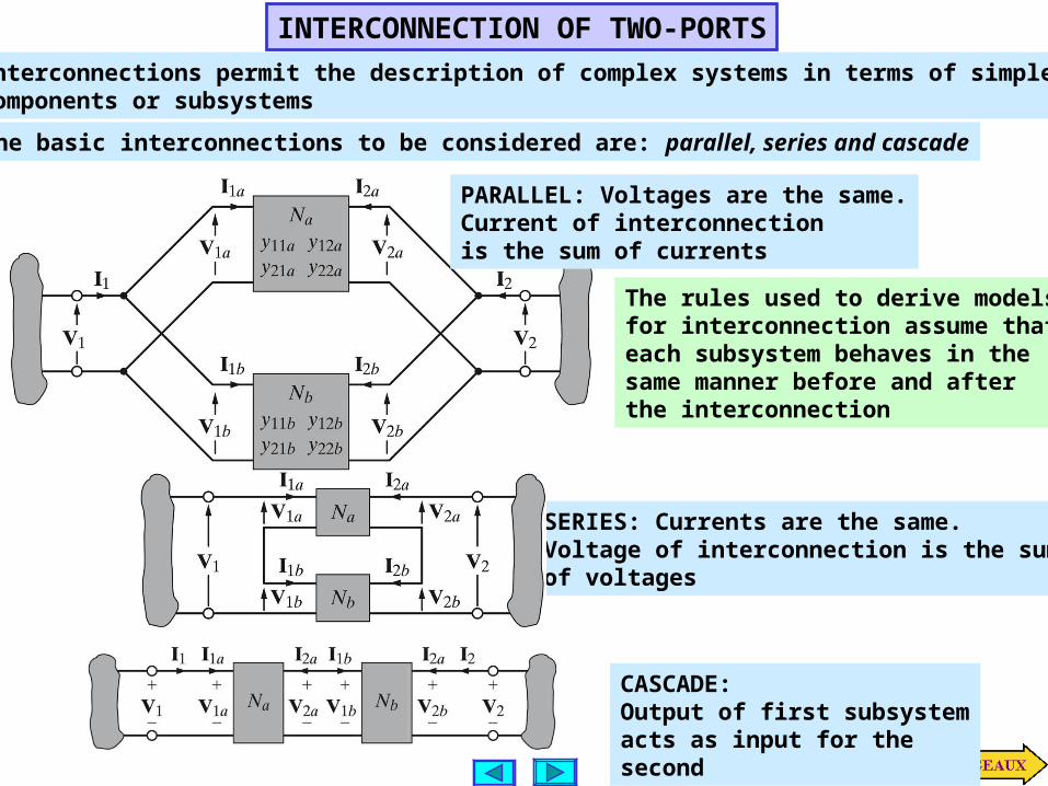
INTERCONNECTION OF TWO-PORTS
Interconnections permit the description of complex systems in terms of simplercomponents or subsystems
The basic interconnections to be considered are: parallel, series and cascade
PARALLEL: Voltages are the same.Current of interconnectionis the sum of currents
The rules used to derive modelsfor interconnection assume thateach subsystem behaves in thesame manner before and afterthe interconnection
SERIES: Currents are the same.Voltage of interconnection is the sumof voltages
CASCADE:Output of first subsystemacts as input for thesecond
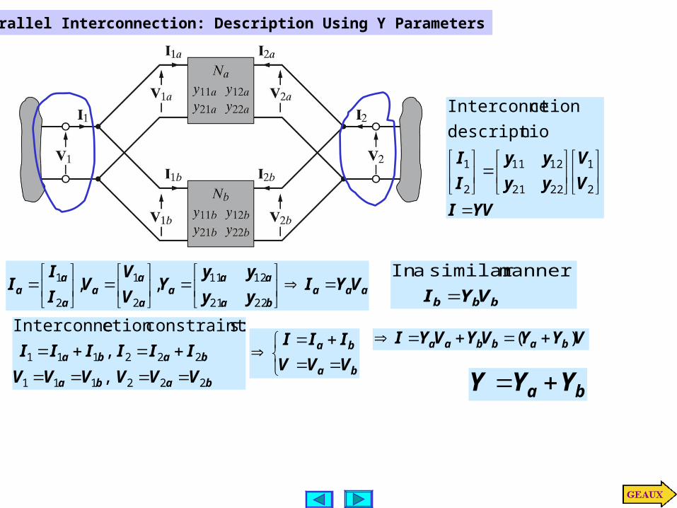
aaaba
aaa
a
aa
a
aa VYI
yy
yyY
V
VV
I
II
2221
1211
2
1
2
1 ,,bbb VYI manner similar a In
baba
baba
VVVVVV
IIIIII
222111
222111
,
,
:sconstraint ctionInterconne
ba
ba
VVV
III
ba YYY
VYYVYVYI babbaa )(
Parallel Interconnection: Description Using Y Parameters
YVI
V
V
yy
yy
I
I
2
1
2221
1211
2
1
ndescriptio
ctionInterconne
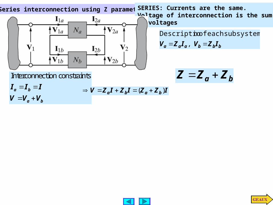
Series interconnection using Z parameters
bbbaaa IZVIZV ,
subsystem each of nDescriptio
Interconnection constraints
a b
a b
I I I
V V V
IZZIZIZV baba )(
ba ZZZ
SERIES: Currents are the same.Voltage of interconnection is the sumof voltages

Cascade connection using transmission parameters
2 1 2 1
1 1 2 2
1 1 2 2
Interconnection constraints:
a b a b
a b
a b
I I V V
V V V V
I I I I
a
a
aa
aa
a
a
I
V
DC
BA
I
V
2
2
1
1
b
b
bb
bb
b
b
I
V
DC
BA
I
V
2
2
1
1
2
2
1
1
I
V
DC
BA
DC
BA
I
V
bb
bb
aa
aa
Matrix multiplication does not commute.Order of the interconnection is important
CASCADE:Output of first subsystemacts as input for thesecond
2
2
1
1
I
V
DC
BA
I
V
221
221
DICVI
BIAVV

LEARNING EXAMPLEFind the Y parameters for the network
11
2
2j1I
1V
2I
2V
1I
1V
2I
2V
12
121 2
II
IjVV
11 12
1 1,
2 2 a ay j y j
21 221 1
,2 2
a ay j y j
212
211
3
2
IIV
IIV
21
13
5
1
31
121
bY
][
2
1
5
2
2
1
5
12
1
5
1
2
1
5
3
Sjj
jjY
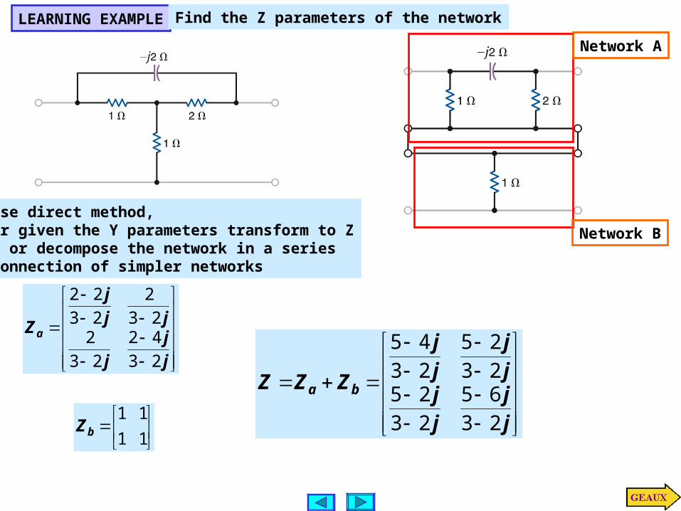
LEARNING EXAMPLEFind the Z parameters of the network
Network A
Network BUse direct method,or given the Y parameters transform to Z… or decompose the network in a seriesconnection of simpler networks
j
j
j
jj
j
Za
23
42
23
223
2
23
22
11
11bZ
j
j
j
jj
j
j
j
ZZZ ba
23
65
23
2523
25
23
45
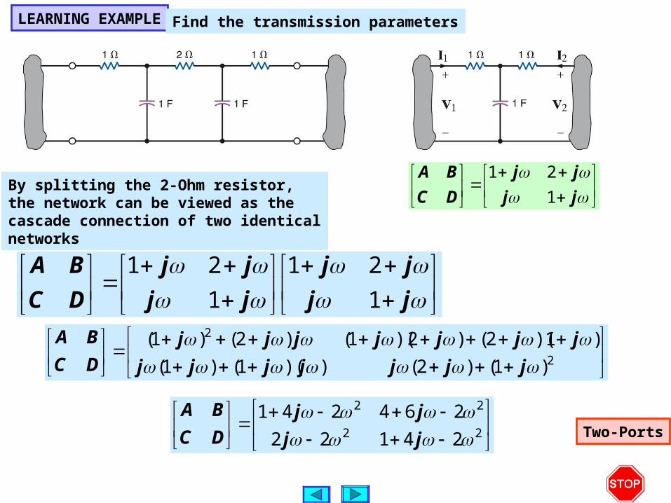
LEARNING EXAMPLEFind the transmission parameters
By splitting the 2-Ohm resistor,the network can be viewed as thecascade connection of two identicalnetworks
jj
jj
jj
jj
DC
BA
1
21
1
21
2
2
)1()2())(1()1(
)1)(2()2)(1()2()1(
jjjjjjj
jjjjjjj
DC
BA
22
22
24122
264241
jj
jj
DC
BA
jj
jj
DC
BA
1
21
Two-Ports