Embed Size (px)
Citation preview
Two-Way (True Full-duplex) WirelessAmir K. Khandani
Electrical and Computer Engineering Department, University of Waterloo, Waterloo, ON, Canada
Abstract—Current wireless systems are one-way (similar towalkie-talkies), meaning that disjoint time or frequency segmentsare used to transmit and to receive. Realization of two-way wire-less has challenged the research community for many years. Thisarticle1 establishes the theory and presents practical realizationof two-way (true full-duplex) wireless. In contrast to the widelyaccepted beliefs, it is shown that two-way wireless is not onlyfeasible, but is fairly simple, with virtually no degradation insignal-to-noise-ratio2. The innovation is in the antenna designand multiple levels for cancelling self-interference. Methods aredeveloped to support Multiple-Input Multiple-Output (MIMO)two-way transmission, and asynchronous two-way links (usefulin networking applications). The developed hardware uses off-the-shelf components, antennas have a simple structure, areomnidirectional (can be directional, if needed), do not suffer frombandwidth limitations, have a small size/spacing, and the increasein overall complexity is minimal. It is shown that two-way wirelesscan do more than doubling the rate. In particular:
1) Facilitates wireless networking. In particular, the ability tohandle asynchronous users enables superimposing a half-duplex, low bit rate, low power, easy to detect network forcontrol signaling superimposed (physical overlay, ratherthan logical) on top of the network of primary full-duplexdata links. The superimposed links are separated from theprimary full-duplex data links in the code domain, anduse time multiplexing plus Carrier Sense Multiple Access(CSMA) among themselves. However, the conventionalproblems of CSMA are avoided as control links operate inparallel with primary full-duplex data links. The physicallayer of control links is designed such that full-duplex datalinks can detect and cancel the interference caused by thesuperimposed control links.
2) Enhances security through desirable jamming.3) Provides the ground to realize unconditional security (be-
yond computational or information theoretical security),using a simple method introduced in this article.
4) Facilitates multi-node distributed & collaborative signaling,including realization of Network Information Theoreticsetups, and cognitive wireless.
5) Exploiting feedback, it improves point-to-point throughput,and enables ultra low power transmission.
6) Doubles the point-to-point throughput.
I. INTRODUCTION
A communication link with capability to support connectionsin both transmit and receive directions at the same time andover the entire frequency band is called full-duplex, or two-way. In contrast, a link that can support the connection inonly one direction at a time is called one-way or half-duplex.Current wireless systems are one-way and rely on either separatetime slots (time division duplex) or separate frequency bands(frequency division duplex) to transmit and to receive. Thesealternatives have their pros and cons, but both suffer from lack ofability to transmit and receive concurrently over entire frequencyband. Even in the context of Orthogonal Frequency DivisionMultiple Access (OFDMA), where different frequency tones are
1Supported by Ontario Ministry of Research and Innovation (ORF-RE).2Due to space limitations, see [1] for details on performance measures.
used to simultaneously service multiple users, there is no methodknown to use the tones in opposite directions. A similar short-coming exists in the context of Code Division Multiple Access(CDMA). Although two-way wireless is theoretically possible, itsimplementation is difficult due to an excessive amount of self-interference, i.e., the interference each transmitter generates toits own receiver(s).
Full-duplex communication is currently used in many appli-cations, e.g., wired telephones, digital subscriber line, wirelesswith directional antennas, and free-space optics. The impactof full-duplex links in these earlier applications is limited todoubling the rate by providing two symmetrical pipes of dataflowing in opposite directions. In contrast, in multi-user wirelesssystems, due to the broadcast nature of transmission (everyonehears everyone else), full-duplex capability has the potential to domore than merely doubling the rate, e.g., it facilitates networking,collaborative transmission, and security.
To cancel the self-interference in analog domain, an AuxiliaryTransmit signal (ATX) is generated from the Primary Transmitsignal (PTX) and added to the received signal in the analogdomain. Prefiltering, e.g., by pre-weighting coefficients appliedto OFDM tones, are calculated for the ATX signal to cancel theself-interference. ATX can be radio frequency (RF) modulatedand added to (i.e., coupled with) the received signal in RFdomain prior to Low Noise Amplifier (LNA). It can be alsoadded to the received signal in analog base-band prior toAnalog-to-Digital converter (A/D), at the cost of using LNAwith a larger dynamic range. In addition to cancellation in theanalog domain, digital subtraction is deployed at the receivebase-band to further reduce the self-interference. In particular,linearity of the Digital-to-Analog converter (D/A) is exploitedto subtract the remaining amount of self-interference from thebase-band received signal (while maintaining and benefiting fromunderlying OFDM structure).
Symmetrical transmit and receive antennas are relativelypositioned to reduce self-interference. In two dimensions, pair-wise symmetric antennas are proposed which have (theoretically)zero coupling over entire frequency range. The idea of symmetryis generalized to three dimensions. It is shown there exist triple-wise symmetric antennas with zero coupling between any pair.For MIMO transmission, two sets of such antennas (to be used fortransmit and receive) can be arranged in three dimensions suchthat any antenna in one set is decoupled from all the antennasin the other set. Such three dimensional structures can be alsoimplemented in 2.5 dimensions using layers of a Printed CircuitBoard (PCB), e.g., by using patch antennas where one arm ofantenna is generated through reflection of the other arm in theground plane. Examples of such a construction are presentedwhere the same patch is used as the transmit antenna, thereceive antenna, and the ATX coupler. This construction is alsogeneralized to MIMO. To further simplify the construction forMIMO, a third class of antenna structures are introduced basedon placing one set of antennas in the plane of zero electric fieldof another set, providing low (but non-zero) coupling.
Implementation: RF transmission is based on 802.11 using a20MHz channel at 2.4 GHz as well as 5Ghz. Transmission poweris about 20dbm which is typical for cellular applications. Thebasic physical layer follows 802.11 in terms of OFDM structure,preamble, synchronization, etc. For hardware implementation,
the software defined radio platform by Lyrtech (now Nutaq) isused, and the final outcome has been tested in outdoor and indoorenvironments, and it essentially works as reliably as a one-waysystem.
Two-way wireless has been of interest over a relatively longperiod of time and there have been some other works addressingthis problem [1]-[11]. Author’s initial interest in this topic startedin 2004, followed by a provisional patent in 2005, actual patentfiled in 2006, which was issued in 2010 [2]. The starting pointfor the author’s work was to use multiple transmit antennaswith transmit beamforming to create a null at the position of areceive antenna. In particular, using two transmit antennas with180 degree phase shifts to create a null at the position of a receiveantenna which is positioned in the middle of the two transmitantennas. The same antenna structure was later rediscoveredin [10][11]. Current article presents a more advanced and maturedesign. The contents of this article have been publicized on-line inApril 2012 [1]. There are several critical components contributingto the excellent performance of the method reported here ascompared to the results reported by others, and in particular byresearch teams from Rice [6]-[9] and Stanford [10][11]:
• Analog Active Cancellation exploiting the linearity of D/Awith proper training for channel measurement. Overall,active cancellation is done in a way that it does notcontradict linearity in the cancellation path. As a result,active cancellation does not need to be precise and any suchlack of precision, which is unavoidable, will be accountedfor (subsequently measured) and compensated in the nextstep in the digital base-band cancellation.
• Antennas are designed to provide (theoretically) zero self-interference over the entire frequency range, includingsupport for MIMO. 3.
• Power Amplifier (PA) modeling and compensation.• Methods to deal with imperfections caused by numerical in-
accuracies, such as rounding effect in FFT/IFFT operations,and methods to optimize accuracy in fixed point arithmeticprior to D/A.4
• Dealing with mismatches in RF demodulation, in particularclock and phase jitter.3.
In addition, compared to other research works, this workincludes support for MIMO, asynchronous clients and presentsseveral new applications to exploit the potential of two-way inwireless networks (broadcast nature of wireless provides theground to benefit from two-way connectivity beyond doublingthe rate).
II. TWO-WAY CONNECTIVITY
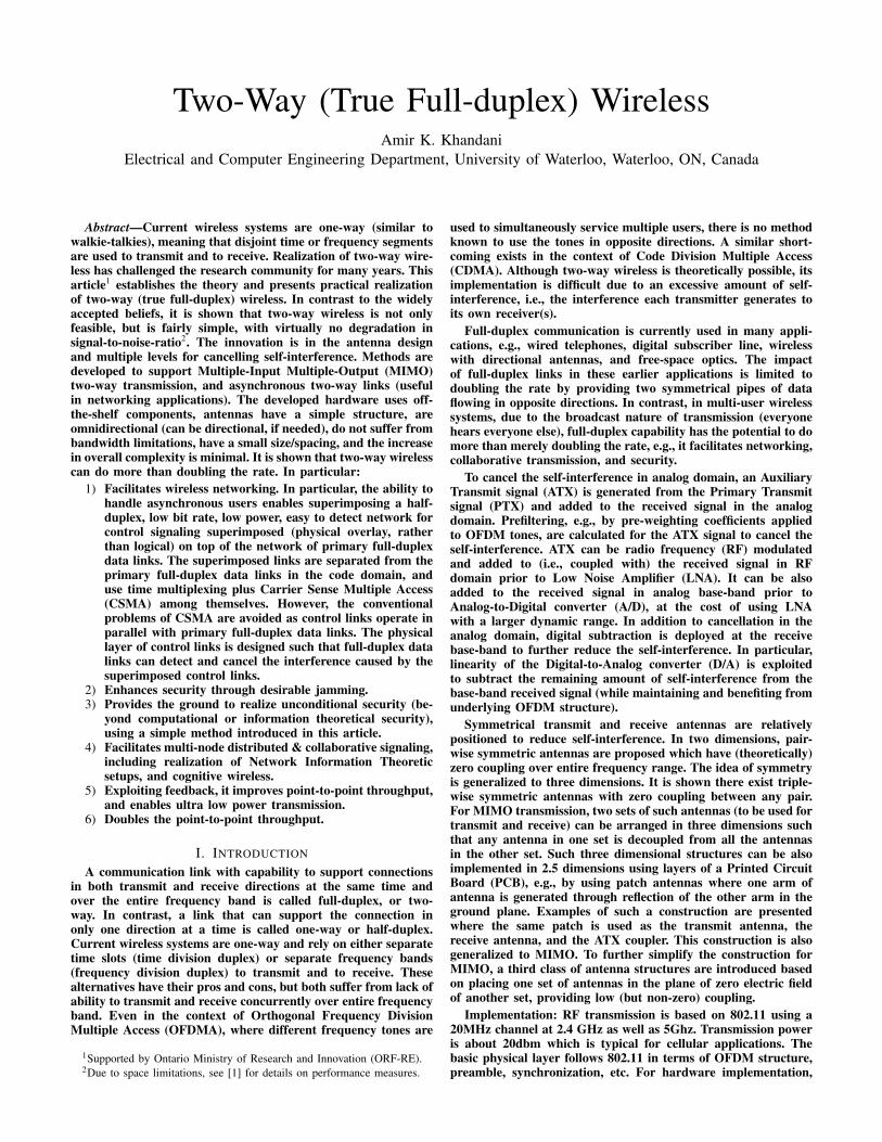
Consider the full-duplex communication network shown inFig. 1, in which an access point is communicating with multipleclients. The access point employs OFDMA to service multipleusers with full-duplex connectivity over each OFDM tone. Theaccess point can also support multiple transmit and multiplereceive antennas to further exploit spatial degrees of freedomto increase rate and/or diversity. In addition, the access pointsupports new incoming clients which can asynchronously jointhe network (without prior time/frequency synchronization).
ATX signal is added to the receive chain to reduce the self-interference in analog domain prior to A/D (preferably priorto LNA). ATX signal can be constructed by weighting eachOFDM tone of TX signal by a proper value to cause cancellation.The filtering operation to construct ATX from PTX can be alsoimplemented in time domain; in which case only one IFFT blockis used. The self-interference remaining in the base-band signalafter analog active cancellation is a linear combination of PTX,
3 [6]-[9] do not discuss antenna design and [10][11] rediscovered the sameantenna structure as in Fig. 1 of the author’s issued patent [2]
4Due to space limitations, refer to [1] for details.
Unit1 with N1 antennas, usually N1=1
Mainly receiving data
Central Unit
with M
antennas,
usually M=K
Common
control
Unit2 with N2 antennas, usually N2=1
Mainly sending data
UnitK with NK antennas, usually NK=1
Mainly receiving data
Fig. 1: 2K pipes of data/control are established over thesame time/frequency where control includes reference fortime/frequency/clock synchronization, channel gain/phase,information for user selection and channel inversion in SDMA,channel matrix in MIMO, ARQ, power control, instruction foradaptive coding and modulation, etc. In SDMA down-link, maindata flow is out of central unit, while in SDMA uplink most dataflow is into the central unit. Common control includes reference fortime/frequency/clock synchronization.
RF Design for Low Coupling
Analog Correction Prior to A/D
Digital Correction in Baseband Transmit Signal
Receive Signal
Strong Interference Done at RF (RF Coupler)
ATX
RX
Terminated
ATX
RX
Done at BB (OP AMP)
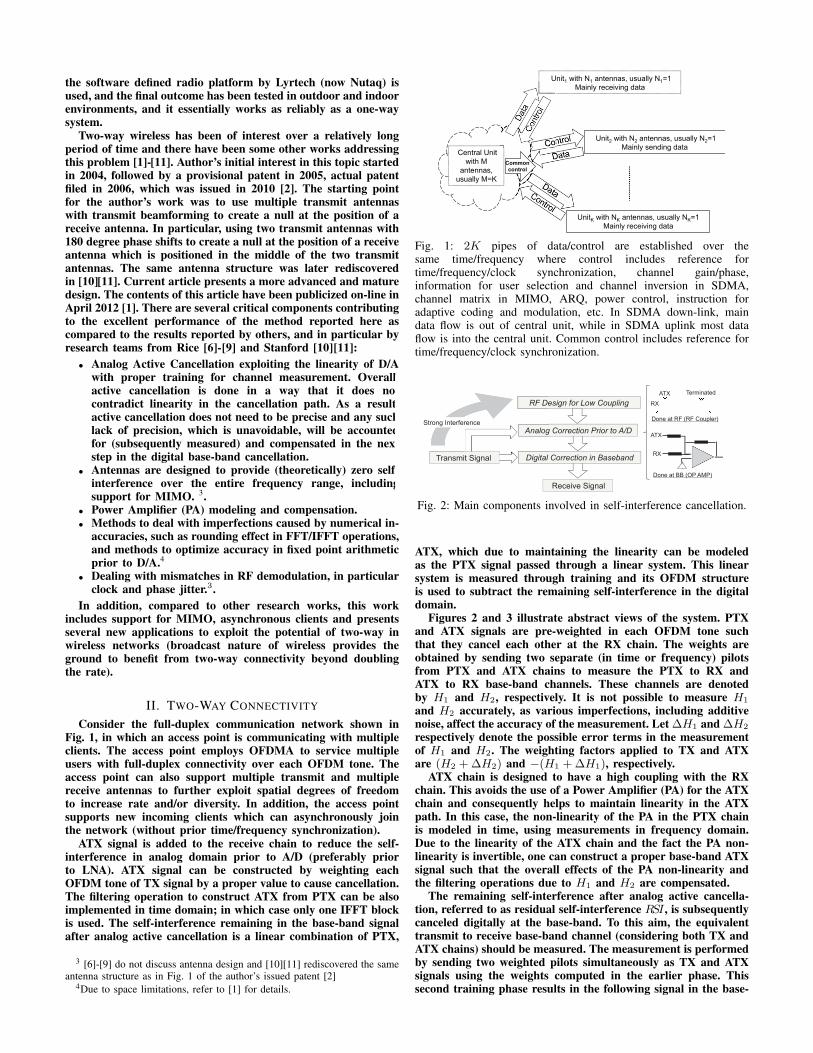
Fig. 2: Main components involved in self-interference cancellation.
ATX, which due to maintaining the linearity can be modeledas the PTX signal passed through a linear system. This linearsystem is measured through training and its OFDM structureis used to subtract the remaining self-interference in the digitaldomain.
Figures 2 and 3 illustrate abstract views of the system. PTXand ATX signals are pre-weighted in each OFDM tone suchthat they cancel each other at the RX chain. The weights areobtained by sending two separate (in time or frequency) pilotsfrom PTX and ATX chains to measure the PTX to RX andATX to RX base-band channels. These channels are denotedby H1 and H2, respectively. It is not possible to measure H1
and H2 accurately, as various imperfections, including additivenoise, affect the accuracy of the measurement. Let ∆H1 and ∆H2
respectively denote the possible error terms in the measurementof H1 and H2. The weighting factors applied to TX and ATXare (H2 +∆H2) and −(H1 +∆H1), respectively.
ATX chain is designed to have a high coupling with the RXchain. This avoids the use of a Power Amplifier (PA) for the ATXchain and consequently helps to maintain linearity in the ATXpath. In this case, the non-linearity of the PA in the PTX chainis modeled in time, using measurements in frequency domain.Due to the linearity of the ATX chain and the fact the PA non-linearity is invertible, one can construct a proper base-band ATXsignal such that the overall effects of the PA non-linearity andthe filtering operations due to H1 and H2 are compensated.
The remaining self-interference after analog active cancella-tion, referred to as residual self-interference RSI , is subsequentlycanceled digitally at the base-band. To this aim, the equivalenttransmit to receive base-band channel (considering both TX andATX chains) should be measured. The measurement is performedby sending two weighted pilots simultaneously as TX and ATXsignals using the weights computed in the earlier phase. Thissecond training phase results in the following signal in the base-
TX
RF Addition
Transmit and Receive with Low Coupling
RF Mod
D/A
PA
D/A
RF Mod
RX Baseband
A/D
TX Baseband
RF Demod
H2
H1
RX −TX(H1∆H
2−H
2∆H
1)
OFDM Data Out
OFDM Data In
RX
−(H1+∆H
1)(H
2+∆H
2)
ATX Baseband
OFDM Data In
Accounting for PA non-linarites & rounding errors
H1∆H
2−H
2∆H
1
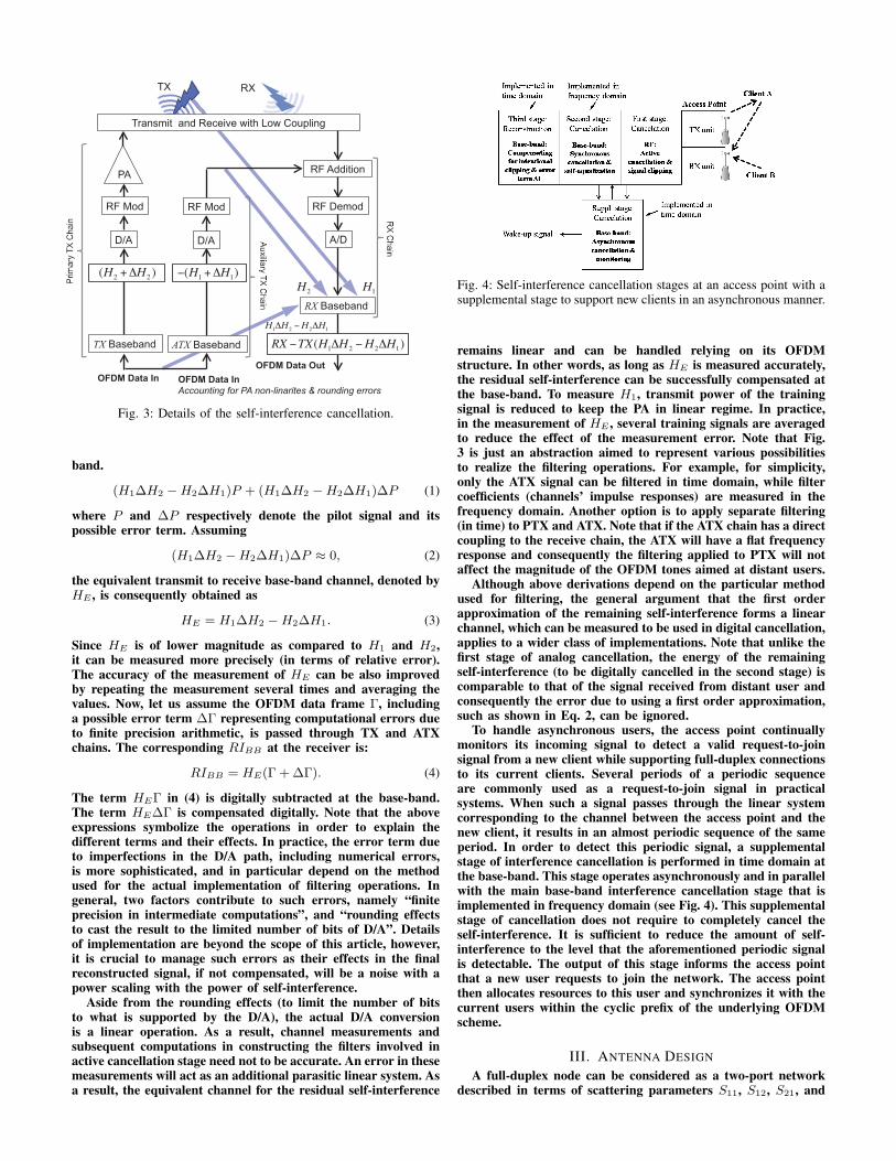
Fig. 3: Details of the self-interference cancellation.
band.
(H1∆H2 −H2∆H1)P + (H1∆H2 −H2∆H1)∆P (1)
where P and ∆P respectively denote the pilot signal and itspossible error term. Assuming
(H1∆H2 −H2∆H1)∆P ≈ 0, (2)
the equivalent transmit to receive base-band channel, denoted byHE , is consequently obtained as
HE = H1∆H2 −H2∆H1. (3)
Since HE is of lower magnitude as compared to H1 and H2,it can be measured more precisely (in terms of relative error).The accuracy of the measurement of HE can be also improvedby repeating the measurement several times and averaging thevalues. Now, let us assume the OFDM data frame Γ, includinga possible error term ∆Γ representing computational errors dueto finite precision arithmetic, is passed through TX and ATXchains. The corresponding RIBB at the receiver is:
RIBB = HE(Γ + ∆Γ). (4)
The term HEΓ in (4) is digitally subtracted at the base-band.The term HE∆Γ is compensated digitally. Note that the aboveexpressions symbolize the operations in order to explain thedifferent terms and their effects. In practice, the error term dueto imperfections in the D/A path, including numerical errors,is more sophisticated, and in particular depend on the methodused for the actual implementation of filtering operations. Ingeneral, two factors contribute to such errors, namely “finiteprecision in intermediate computations”, and “rounding effectsto cast the result to the limited number of bits of D/A”. Detailsof implementation are beyond the scope of this article, however,it is crucial to manage such errors as their effects in the finalreconstructed signal, if not compensated, will be a noise with apower scaling with the power of self-interference.
Aside from the rounding effects (to limit the number of bitsto what is supported by the D/A), the actual D/A conversionis a linear operation. As a result, channel measurements andsubsequent computations in constructing the filters involved inactive cancellation stage need not to be accurate. An error in thesemeasurements will act as an additional parasitic linear system. Asa result, the equivalent channel for the residual self-interference
Fig. 4: Self-interference cancellation stages at an access point with asupplemental stage to support new clients in an asynchronous manner.
remains linear and can be handled relying on its OFDMstructure. In other words, as long as HE is measured accurately,the residual self-interference can be successfully compensated atthe base-band. To measure H1, transmit power of the trainingsignal is reduced to keep the PA in linear regime. In practice,in the measurement of HE , several training signals are averagedto reduce the effect of the measurement error. Note that Fig.3 is just an abstraction aimed to represent various possibilitiesto realize the filtering operations. For example, for simplicity,only the ATX signal can be filtered in time domain, while filtercoefficients (channels’ impulse responses) are measured in thefrequency domain. Another option is to apply separate filtering(in time) to PTX and ATX. Note that if the ATX chain has a directcoupling to the receive chain, the ATX will have a flat frequencyresponse and consequently the filtering applied to PTX will notaffect the magnitude of the OFDM tones aimed at distant users.
Although above derivations depend on the particular methodused for filtering, the general argument that the first orderapproximation of the remaining self-interference forms a linearchannel, which can be measured to be used in digital cancellation,applies to a wider class of implementations. Note that unlike thefirst stage of analog cancellation, the energy of the remainingself-interference (to be digitally cancelled in the second stage) iscomparable to that of the signal received from distant user andconsequently the error due to using a first order approximation,such as shown in Eq. 2, can be ignored.
To handle asynchronous users, the access point continuallymonitors its incoming signal to detect a valid request-to-joinsignal from a new client while supporting full-duplex connectionsto its current clients. Several periods of a periodic sequenceare commonly used as a request-to-join signal in practicalsystems. When such a signal passes through the linear systemcorresponding to the channel between the access point and thenew client, it results in an almost periodic sequence of the sameperiod. In order to detect this periodic signal, a supplementalstage of interference cancellation is performed in time domain atthe base-band. This stage operates asynchronously and in parallelwith the main base-band interference cancellation stage that isimplemented in frequency domain (see Fig. 4). This supplementalstage of cancellation does not require to completely cancel theself-interference. It is sufficient to reduce the amount of self-interference to the level that the aforementioned periodic signalis detectable. The output of this stage informs the access pointthat a new user requests to join the network. The access pointthen allocates resources to this user and synchronizes it with thecurrent users within the cyclic prefix of the underlying OFDMscheme.
III. ANTENNA DESIGN
A full-duplex node can be considered as a two-port networkdescribed in terms of scattering parameters S11, S12, S21, and
y
x
z
J
-d
E
+d
TX
RX
y
x
z
J
TX
RX
A
A’
B
B’
y
J x
z
D(x,y,z) D(-x,y,z)
D(x,-y,z) D(-x,-y,z)
x -x !"#$%&"'%()*%J
y -y +,)*$ J
z -z !"#$%&"'%()*%J
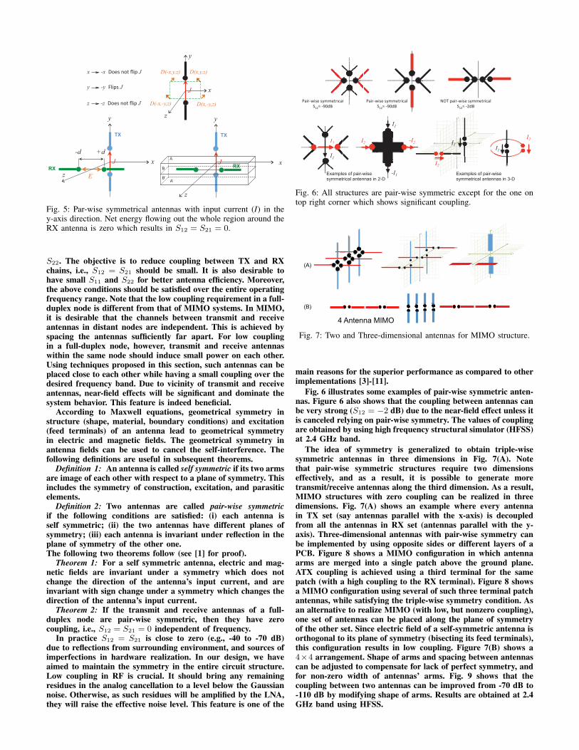
Fig. 5: Par-wise symmetrical antennas with input current (I) in they-axis direction. Net energy flowing out the whole region around theRX antenna is zero which results in S12 = S21 = 0.
S22. The objective is to reduce coupling between TX and RXchains, i.e., S12 = S21 should be small. It is also desirable tohave small S11 and S22 for better antenna efficiency. Moreover,the above conditions should be satisfied over the entire operatingfrequency range. Note that the low coupling requirement in a full-duplex node is different from that of MIMO systems. In MIMO,it is desirable that the channels between transmit and receiveantennas in distant nodes are independent. This is achieved byspacing the antennas sufficiently far apart. For low couplingin a full-duplex node, however, transmit and receive antennaswithin the same node should induce small power on each other.Using techniques proposed in this section, such antennas can beplaced close to each other while having a small coupling over thedesired frequency band. Due to vicinity of transmit and receiveantennas, near-field effects will be significant and dominate thesystem behavior. This feature is indeed beneficial.
According to Maxwell equations, geometrical symmetry instructure (shape, material, boundary conditions) and excitation(feed terminals) of an antenna lead to geometrical symmetryin electric and magnetic fields. The geometrical symmetry inantenna fields can be used to cancel the self-interference. Thefollowing definitions are useful in subsequent theorems.
Definition 1: An antenna is called self symmetric if its two armsare image of each other with respect to a plane of symmetry. Thisincludes the symmetry of construction, excitation, and parasiticelements.
Definition 2: Two antennas are called pair-wise symmetricif the following conditions are satisfied: (i) each antenna isself symmetric; (ii) the two antennas have different planes ofsymmetry; (iii) each antenna is invariant under reflection in theplane of symmetry of the other one.The following two theorems follow (see [1] for proof).
Theorem 1: For a self symmetric antenna, electric and mag-netic fields are invariant under a symmetry which does notchange the direction of the antenna’s input current, and areinvariant with sign change under a symmetry which changes thedirection of the antenna’s input current.
Theorem 2: If the transmit and receive antennas of a full-duplex node are pair-wise symmetric, then they have zerocoupling, i.e., S12 = S21 = 0 independent of frequency.
In practice S12 = S21 is close to zero (e.g., -40 to -70 dB)due to reflections from surrounding environment, and sources ofimperfections in hardware realization. In our design, we haveaimed to maintain the symmetry in the entire circuit structure.Low coupling in RF is crucial. It should bring any remainingresidues in the analog cancellation to a level below the Gaussiannoise. Otherwise, as such residues will be amplified by the LNA,they will raise the effective noise level. This feature is one of the
I2
Examples of pair-wise symmetrical antennas in 2-D 2-D
22III2
II2
I1
-I1
I2 -I
2
I1
I2
I1
I1
I2
!"#$%&#'()'*++(,$#-".)
/012)%3456)
Examples of pair-wise symmetrical antennas in 3-D
789):"#$%&#'()'*++(,$#-".))
/012)%156)
!"#$%&#'()'*++(,$#-".)
/012)%3456)
Fig. 6: All structures are pair-wise symmetric except for the one ontop right corner which shows significant coupling.
4 Antenna MIMO
(B)
(A)
Fig. 7: Two and Three-dimensional antennas for MIMO structure.
main reasons for the superior performance as compared to otherimplementations [3]-[11].
Fig. 6 illustrates some examples of pair-wise symmetric anten-nas. Figure 6 also shows that the coupling between antennas canbe very strong (S12 = −2 dB) due to the near-field effect unless itis canceled relying on pair-wise symmetry. The values of couplingare obtained by using high frequency structural simulator (HFSS)at 2.4 GHz band.
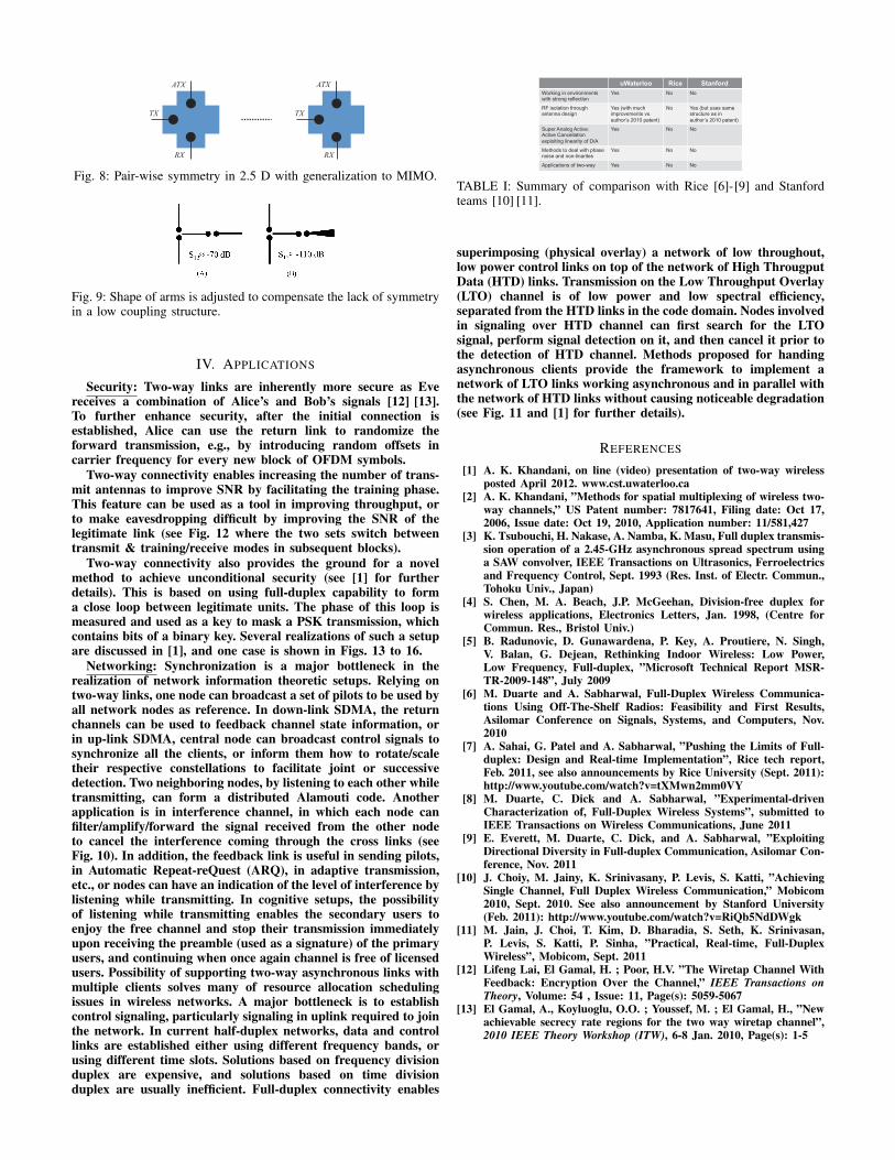
The idea of symmetry is generalized to obtain triple-wisesymmetric antennas in three dimensions in Fig. 7(A). Notethat pair-wise symmetric structures require two dimensionseffectively, and as a result, it is possible to generate moretransmit/receive antennas along the third dimension. As a result,MIMO structures with zero coupling can be realized in threedimensions. Fig. 7(A) shows an example where every antennain TX set (say antennas parallel with the x-axis) is decoupledfrom all the antennas in RX set (antennas parallel with the y-axis). Three-dimensional antennas with pair-wise symmetry canbe implemented by using opposite sides or different layers of aPCB. Figure 8 shows a MIMO configuration in which antennaarms are merged into a single patch above the ground plane.ATX coupling is achieved using a third terminal for the samepatch (with a high coupling to the RX terminal). Figure 8 showsa MIMO configuration using several of such three terminal patchantennas, while satisfying the triple-wise symmetry condition. Asan alternative to realize MIMO (with low, but nonzero coupling),one set of antennas can be placed along the plane of symmetryof the other set. Since electric field of a self-symmetric antenna isorthogonal to its plane of symmetry (bisecting its feed terminals),this configuration results in low coupling. Figure 7(B) shows a4×4 arrangement. Shape of arms and spacing between antennascan be adjusted to compensate for lack of perfect symmetry, andfor non-zero width of antennas’ arms. Fig. 9 shows that thecoupling between two antennas can be improved from -70 dB to-110 dB by modifying shape of arms. Results are obtained at 2.4GHz band using HFSS.
ATX
TX
RX
ATX
TX
RX
Fig. 8: Pair-wise symmetry in 2.5 D with generalization to MIMO.
Fig. 9: Shape of arms is adjusted to compensate the lack of symmetryin a low coupling structure.
IV. APPLICATIONS
Security: Two-way links are inherently more secure as Evereceives a combination of Alice’s and Bob’s signals [12] [13].To further enhance security, after the initial connection isestablished, Alice can use the return link to randomize theforward transmission, e.g., by introducing random offsets incarrier frequency for every new block of OFDM symbols.
Two-way connectivity enables increasing the number of trans-mit antennas to improve SNR by facilitating the training phase.This feature can be used as a tool in improving throughput, orto make eavesdropping difficult by improving the SNR of thelegitimate link (see Fig. 12 where the two sets switch betweentransmit & training/receive modes in subsequent blocks).
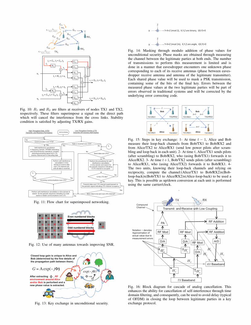
Two-way connectivity also provides the ground for a novelmethod to achieve unconditional security (see [1] for furtherdetails). This is based on using full-duplex capability to forma close loop between legitimate units. The phase of this loop ismeasured and used as a key to mask a PSK transmission, whichcontains bits of a binary key. Several realizations of such a setupare discussed in [1], and one case is shown in Figs. 13 to 16.
Networking: Synchronization is a major bottleneck in therealization of network information theoretic setups. Relying ontwo-way links, one node can broadcast a set of pilots to be used byall network nodes as reference. In down-link SDMA, the returnchannels can be used to feedback channel state information, orin up-link SDMA, central node can broadcast control signals tosynchronize all the clients, or inform them how to rotate/scaletheir respective constellations to facilitate joint or successivedetection. Two neighboring nodes, by listening to each other whiletransmitting, can form a distributed Alamouti code. Anotherapplication is in interference channel, in which each node canfilter/amplify/forward the signal received from the other nodeto cancel the interference coming through the cross links (seeFig. 10). In addition, the feedback link is useful in sending pilots,in Automatic Repeat-reQuest (ARQ), in adaptive transmission,etc., or nodes can have an indication of the level of interference bylistening while transmitting. In cognitive setups, the possibilityof listening while transmitting enables the secondary users toenjoy the free channel and stop their transmission immediatelyupon receiving the preamble (used as a signature) of the primaryusers, and continuing when once again channel is free of licensedusers. Possibility of supporting two-way asynchronous links withmultiple clients solves many of resource allocation schedulingissues in wireless networks. A major bottleneck is to establishcontrol signaling, particularly signaling in uplink required to jointhe network. In current half-duplex networks, data and controllinks are established either using different frequency bands, orusing different time slots. Solutions based on frequency divisionduplex are expensive, and solutions based on time divisionduplex are usually inefficient. Full-duplex connectivity enables
uWaterloo Rice Stanford
Working in environments with strong reflection
Yes No No
RF isolation through antenna design
Yes (with much improvements vs.
author’s 2010 patent)
No Yes (but uses same structure as in
author’s 2010 patent)
Super Analog Active: Active Cancellation
exploiting linearity of D/A
Yes No No
Methods to deal with phase noise and non-linarites
Yes No No
Applications of two-way Yes No No
TABLE I: Summary of comparison with Rice [6]-[9] and Stanfordteams [10] [11].
superimposing (physical overlay) a network of low throughout,low power control links on top of the network of High ThrougputData (HTD) links. Transmission on the Low Throughput Overlay(LTO) channel is of low power and low spectral efficiency,separated from the HTD links in the code domain. Nodes involvedin signaling over HTD channel can first search for the LTOsignal, perform signal detection on it, and then cancel it prior tothe detection of HTD channel. Methods proposed for handingasynchronous clients provide the framework to implement anetwork of LTO links working asynchronous and in parallel withthe network of HTD links without causing noticeable degradation(see Fig. 11 and [1] for further details).
REFERENCES
[1] A. K. Khandani, on line (video) presentation of two-way wirelessposted April 2012. www.cst.uwaterloo.ca
[2] A. K. Khandani, ”Methods for spatial multiplexing of wireless two-way channels,” US Patent number: 7817641, Filing date: Oct 17,2006, Issue date: Oct 19, 2010, Application number: 11/581,427
[3] K. Tsubouchi, H. Nakase, A. Namba, K. Masu, Full duplex transmis-sion operation of a 2.45-GHz asynchronous spread spectrum usinga SAW convolver, IEEE Transactions on Ultrasonics, Ferroelectricsand Frequency Control, Sept. 1993 (Res. Inst. of Electr. Commun.,Tohoku Univ., Japan)
[4] S. Chen, M. A. Beach, J.P. McGeehan, Division-free duplex forwireless applications, Electronics Letters, Jan. 1998, (Centre forCommun. Res., Bristol Univ.)
[5] B. Radunovic, D. Gunawardena, P. Key, A. Proutiere, N. Singh,V. Balan, G. Dejean, Rethinking Indoor Wireless: Low Power,Low Frequency, Full-duplex, ”Microsoft Technical Report MSR-TR-2009-148”, July 2009
[6] M. Duarte and A. Sabharwal, Full-Duplex Wireless Communica-tions Using Off-The-Shelf Radios: Feasibility and First Results,Asilomar Conference on Signals, Systems, and Computers, Nov.2010
[7] A. Sahai, G. Patel and A. Sabharwal, ”Pushing the Limits of Full-duplex: Design and Real-time Implementation”, Rice tech report,Feb. 2011, see also announcements by Rice University (Sept. 2011):http://www.youtube.com/watch?v=tXMwn2mm0VY
[8] M. Duarte, C. Dick and A. Sabharwal, ”Experimental-drivenCharacterization of, Full-Duplex Wireless Systems”, submitted toIEEE Transactions on Wireless Communications, June 2011
[9] E. Everett, M. Duarte, C. Dick, and A. Sabharwal, ”ExploitingDirectional Diversity in Full-duplex Communication, Asilomar Con-ference, Nov. 2011
[10] J. Choiy, M. Jainy, K. Srinivasany, P. Levis, S. Katti, ”AchievingSingle Channel, Full Duplex Wireless Communication,” Mobicom2010, Sept. 2010. See also announcement by Stanford University(Feb. 2011): http://www.youtube.com/watch?v=RiQb5NdDWgk
[11] M. Jain, J. Choi, T. Kim, D. Bharadia, S. Seth, K. Srinivasan,P. Levis, S. Katti, P. Sinha, ”Practical, Real-time, Full-DuplexWireless”, Mobicom, Sept. 2011
[12] Lifeng Lai, El Gamal, H. ; Poor, H.V. ”The Wiretap Channel WithFeedback: Encryption Over the Channel,” IEEE Transactions onTheory, Volume: 54 , Issue: 11, Page(s): 5059-5067
[13] El Gamal, A., Koyluoglu, O.O. ; Youssef, M. ; El Gamal, H., ”Newachievable secrecy rate regions for the two way wiretap channel”,2010 IEEE Theory Workshop (ITW), 6-8 Jan. 2010, Page(s): 1-5
r1
= C11
t1+ C
21 t2
r2
= C12
t1+ C
22 t2
t1
= R1 r
1+ s
1
t2
= R2 r
2+ s
2
R1
r1
s1
t1
C11
G11
C12
G12
R2
r2
s2
+ t2
C22
G22
C21
G21
+
+
+
r2
= G12
t1+ G
22 t2
+
r1
= G11
t1+ G
21 t2
+
G11
G21
RX
1
RX2
TX2
TX1
G12
G22
TXTX1
C11
C21
C12
C22
R1=
G21
G21C11−G
11C21
R2=
G12
G12C22−G
22C12
Fig. 10: R1 and R2 are filters at receivers of nodes TX1 and TX2,respectively. These filters superimpose a signal on the direct pathwhich will cancel the interference from the cross links. Stabilitycondition is satisfied by adjusting TX/RX gains.
Unit is Active
Self-interference cancellation
in frequency domain, OFDMA networking
and transmit/receive operations, possibly
detecting/cancelling signal from LTO
receive channel prior to decoding data
High Throughput Data (HTD)
Transmits and Receives (Full Duplex)
Low Throughput Overlay (LTO)
Transmits OR receives (Half Duplex)
Transmit data over LTO channel superimposed on
the periodic signal indicating LTO channel occupancy
Perform the procedures for self-
interference cancellation
in time domain and search for
the periodic sequence indicating
if LTO channel is occupied
Is the LTO idle? No
Data is received over LTO? Yes No
Yes
More data to be sent over LTO channel?
Yes
No
Perform self interference cancellation in time domain &
search for the periodic sequence indicating if a node
wants to initiate communications over LTO
Incoming communications over LTO?
No
Yes
Yes
No
Send data over LTO?
A
A
Perform self interference
cancellation in time
domain & receive data
over LTO channel sub-
until all data is received.
Communication over HTD?
Yes
No
Fig. 11: Flow chart for superimposed networking.
!
"
!
"
!
"
!
"
!
"
!
"
!
"
!
"
!
"
!
"
!
"
!
"
!
"
!
"
!
"
!
"
!
"
Even numbered blocks
Odd numbered blocks
Fig. 12: Use of many antennas towards improving SNR.
G = Α exp(− jΦ)
Closed loop gain is unique to Alice and
Bob (determined by the fine details of
the propagation path between them).
After extracting , RF
environment around Alice
and/or Bob is perturbed and a
new phase value is extracted.
Φ F
ice
d and a
exp(− jΦ)
Φ⇒
Fig. 13: Key exchange in unconditional security.
+
!"
#$%&!"'()*"+,-""%-#-!"./0"123./4-""5'%6#,$7"%"
!"
#$%&!"'()*"+8,-""%-#-!"./0".39:0-""5'%6#,$7"%" +
Fig. 14: Masking through modulo addition of phase values forunconditional security. Phase masks are obtained through measuringthe channel between the legitimate parties at both ends. The numberof transmissions to perform this measurement is limited and isdone in a manner that eavesdropper encounters one unknown phasecorresponding to each of its receive antennas (phase between eaves-dropper receive antenna and antenna of the legitimate transmitter).Each shared phase value will be used to mask a PSK transmission,containing some of the bits of the final key. Errors between themeasured phase values at the two legitimate parties will be part oferrors observed in traditional systems and will be corrected by theunderlying error correcting code.
TX1/RX1 TX2/RX2
t
t
t
t
X1 TX1/RX 2 TX2/RX2
t t
TX1/RX1 TX2/RX2
Bob
Alice TX1/RX1 TX2/RX2
t+1
t+1
t+1 t+1 t+1
X1 TX1/RX 2 TX2/RX2
t+1
TX1/RX1 TX2/RX2
Bob
Alice
Fig. 15: Steps in key exchange: 1- At time t − 1, Alice and Bobmeasure their loop-back channels from Bob/TX1 to Bob/RX2 andfrom Alice/TX2 to Alice/RX1 (send low power pilots after scram-bling and loop back in each unit). 2- At time t, Alice/TX1 sends pilots(after scrambling) to Bob/RX2, who (using Bob/TX1) forwards it toAlice/RX2. 3- At time t+1, Bob/TX2 sends pilots (after scrambling)to Alice/RX1, who (using Alice/TX2) forwards it to Bob/RX1. 4-The two units, knowing their loop-back channels and relying onreciprocity, compute the channel:(Alice/TX1 to Bob/RX2)x(Bob-loop-back)x(Bob/TX1 to Alice/RX2)x(Alice-loop-back) to be used akey. This is possible as up/down conversion at each unit is performedusing the same carrier/clock.
.
TX
RF Addition
Transmit and Receive with Low Coupling
RF Mod
D/A
PA
RX Baseband
A/D
RF Addition
H4
Transmit and Receive with Low Coupling Transmit and Receive with Low Coupling
H2
H1
RX
RF Mod
H2
~
H3
~
RF Mod D/A
D/A
−H4
~
TX Baseband
H3
−H1
~
Compound Channel
Notation ~ denotes Approximation of
actual value due to
measurement errors
Fig. 16: Block diagram for cascade of analog cancellation. Thisenhances the ability for cancellation of self-interference through timedomain filtering, and consequently, can be used to avoid delay (typicalof OFDM) in closing the loop between legitimate parties in a keyexchange protocol.