Embed Size (px)
Citation preview

SN 29343138 TX-L5.E
AV Receiver
TX-L5Instruction Manual
Thank you for purchasing the Onkyo AV Receiver.Please read this manual thoroughly before makingconnections and turning on the power.Following the instructions in this manual will enableyou to obtain optimum performance and listeningenjoyment from your new AV Receiver.Please retain this manual for future reference.
Contents
Getting started
Before Using Your AV Receiver 2
Other
Enjoying Surround mode/Recording
Enjoying music or videos
Turning on the AV Receiver/Speaker Setup

2
SN 29343138 TX-L5.E
1. Read Instructions – All the safety and operating instructionsshould be read before the appliance is operated.
2. Retain Instructions – The safety and operating instructionsshould be retained for future reference.
3. Heed Warnings – All warnings on the appliance and in theoperating instructions should be adhered to.
4. Follow Instructions – All operating and use instructions shouldbe followed.
5. Cleaning – Unplug the appliance from the wall outlet beforecleaning. The appliance should be cleaned only asrecommended by the manufacturer.
6. Attachments – Do not use attachments not recommended bythe appliance manufacturer as they may cause hazards.
7. Water and Moisture – Do not use the appliance near water –forexample, near a bath tub, wash bowl, kitchen sink, or laundrytub; in a wet basement; or near a swimming pool; and the like.
8. Accessories – Do not place the appliance on an unstable cart,stand, tripod, bracket, or table. The appliance may fall, causingserious injury to a child or adult, and serious damage to theappliance. Use only with a cart, stand, tripod, bracket, or tablerecommended by the manufacturer, or sold with the appliance.Any mounting of the appliance should follow the manufacturer’sinstructions, and should use a mounting accessoryrecommended by the manufacturer.
9. An appliance and cart combinationshould be moved with care. Quickstops, excessive force, and unevensurfaces may cause the applianceand cart combination to overturn.
10.Ventilation – Slots and openings inthe cabinet are provided forventilation and to ensure reliableoperation of the appliance and to protect it from overheating, andthese openings must not be blocked or covered. The openingsshould never be blocked by placing the appliance on a bed, sofa,rug, or other similar surface. The appliance should not be placedin a built-in installation such as a bookcase or rack unless properventilation is provided. There should be free space of at least 20cm (8 in.) and an opening behind the appliance.
11.Power Sources – The appliance should be operated only fromthe type of power source indicated on the marking label. If youare not sure of the type of power supply to your home, consultyour appliance dealer or local power company.
12.Grounding or Polarization – The appliance may be equippedwith a polarized alternating current line plug (a plug having oneblade wider than the other). This plug will fit into the power outletonly one way. This is a safety feature. If you are unable to insertthe plug fully into the outlet, try reversing the plug. If the plugshould still fail to fit, contact your electrician to replace yourobsolete outlet. Do not defeat the safety purpose of the polarizedplug.
13.Power-Cord Protection – Power-supply cords should be routedso that they are not likely to be walked on or pinched by itemsplaced upon or against them, paying particular attention to cordsat plugs, convenience receptacles, and the point where they exitfrom the appliance.
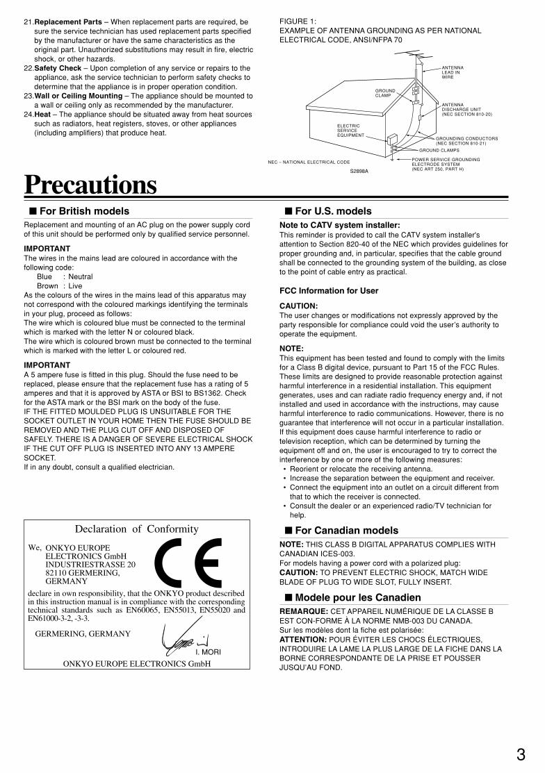
14.Outdoor Antenna Grounding – If an outside antenna or cablesystem is connected to the appliance, be sure the antenna orcable system is grounded so as to provide some protectionagainst voltage surges and built-up static charges. Article 810 ofthe National Electrical Code, ANSI/NFPA 70, provides informationwith regard to proper grounding of the mast and supportingstructure, grounding of the lead-in wire to an antenna-dischargeunit, size of grounding conductors, location of antenna-dischargeunit, connection to grounding electrodes, and requirements forthe grounding electrode. See Figure 1.
15.Lightning – For added protection for the appliance during alightning storm, or when it is left unattended and unused for longperiods of time, unplug it from the wall outlet and disconnect theantenna or cable system. This will prevent damage to theappliance due to lightning and power-line surges.
16.Power Lines – An outside antenna system should not be locatedin the vicinity of overhead power lines or other electric light orpower circuits, or where it can fall into such power lines orcircuits. When installing an outside antenna system, extremecare should be taken to keep from touching such power lines orcircuits as contact with them might be fatal.
17.Overloading – Do not overload wall outlets, extension cords, orintegral convenience receptacles as this can result in a risk of fireor electric shock.
18.Object and Liquid Entry – Never push objects of any kind intothe appliance through openings as they may touch dangerousvoltage points or short-out parts that could result in a fire orelectric shock. Never spill liquid of any kind on the appliance.
19.Servicing – Do not attempt to service the appliance yourself asopening or removing covers may expose you to dangerousvoltage or other hazards. Refer all servicing to qualified servicepersonnel.
20.Damage Requiring Service – Unplug the appliance form thewall outlet and refer servicing to qualified service personnelunder the following conditions:A. When the power-supply cord or plug is damaged,B. If liquid has been spilled, or objects have fallen into the
appliance,C. If the appliance has been exposed to rain or water,D. If the appliance does not operate normally by following the
operating instructions. Adjust only those controls that arecovered by the operating instructions as an improperadjustment of other controls may result in damage and willoften require extensive work by a qualified technician torestore the appliance to its normal operation,
E. If the appliance has been dropped or damaged in any way,and
F. When the appliance exhibits a distinct change in performance– this indicates a need for service.
Important Safeguards
PORTABLE CART WARNING
S3125A
WARNING:TO REDUCE THE RISK OF FIRE ORELECTRIC SHOCK, DO NOT EXPOSE THISAPPLIANCE TO RAIN OR MOISTURE.
CAUTION:TO REDUCE THE RISK OF ELECTRICSHOCK, DO NOT REMOVE COVER (ORBACK).NO USER-SERVICEABLE PARTS INSIDE.REFER SERVICING TO QUALIFIED SERVICEPERSONNEL.
The lightning flash with arrowheadsymbol, within an equilateral triangle, isintended to alert the user to the presenceof uninsulated “dangerous voltage” withinthe product’s enclosure that may be ofsufficient magnitude to constitute a risk ofelectric shock to persons.
The exclamation point within anequilateral triangle is intended to alert theuser to the presence of importantoperating and maintenance (servicing)instructions in the literature accompanyingthe appliance.
RISQUE DE CHOC ELECTRIQUENE PAS OUVRIR
AVIS
RISK OF ELECTRIC SHOCKDO NOT OPEN
WARNING
3
SN 29343138 TX-L5.E
For British modelsReplacement and mounting of an AC plug on the power supply cordof this unit should be performed only by qualified service personnel.
IMPORTANTThe wires in the mains lead are coloured in accordance with thefollowing code:
Blue : NeutralBrown : Live
As the colours of the wires in the mains lead of this apparatus maynot correspond with the coloured markings identifying the terminalsin your plug, proceed as follows:The wire which is coloured blue must be connected to the terminalwhich is marked with the letter N or coloured black.The wire which is coloured brown must be connected to the terminalwhich is marked with the letter L or coloured red.
IMPORTANTA 5 ampere fuse is fitted in this plug. Should the fuse need to bereplaced, please ensure that the replacement fuse has a rating of 5amperes and that it is approved by ASTA or BSI to BS1362. Checkfor the ASTA mark or the BSI mark on the body of the fuse.IF THE FITTED MOULDED PLUG IS UNSUITABLE FOR THESOCKET OUTLET IN YOUR HOME THEN THE FUSE SHOULD BEREMOVED AND THE PLUG CUT OFF AND DISPOSED OFSAFELY. THERE IS A DANGER OF SEVERE ELECTRICAL SHOCKIF THE CUT OFF PLUG IS INSERTED INTO ANY 13 AMPERESOCKET.If in any doubt, consult a qualified electrician.
Precautions
ANTENNADISCHARGE UNIT(NEC SECTION 810-20)
GROUNDING CONDUCTORS(NEC SECTION 810-21)
GROUND CLAMPS
POWER SERVICE GROUNDINGELECTRODE SYSTEM(NEC ART 250, PART H)
NEC – NATIONAL ELECTRICAL CODE
ELECTRICSERVICEEQUIPMENT
GROUNDCLAMP
ANTENNALEAD INWIRE
S2898A
21.Replacement Parts – When replacement parts are required, besure the service technician has used replacement parts specifiedby the manufacturer or have the same characteristics as theoriginal part. Unauthorized substitutions may result in fire, electricshock, or other hazards.
22.Safety Check – Upon completion of any service or repairs to theappliance, ask the service technician to perform safety checks todetermine that the appliance is in proper operation condition.
23.Wall or Ceiling Mounting – The appliance should be mounted toa wall or ceiling only as recommended by the manufacturer.
24.Heat – The appliance should be situated away from heat sourcessuch as radiators, heat registers, stoves, or other appliances(including amplifiers) that produce heat.
For U.S. modelsNote to CATV system installer:This reminder is provided to call the CATV system installer'sattention to Section 820-40 of the NEC which provides guidelines forproper grounding and, in particular, specifies that the cable groundshall be connected to the grounding system of the building, as closeto the point of cable entry as practical.
FCC Information for User
CAUTION:The user changes or modifications not expressly approved by theparty responsible for compliance could void the user’s authority tooperate the equipment.
NOTE:This equipment has been tested and found to comply with the limitsfor a Class B digital device, pursuant to Part 15 of the FCC Rules.These limits are designed to provide reasonable protection againstharmful interference in a residential installation. This equipmentgenerates, uses and can radiate radio frequency energy and, if notinstalled and used in accordance with the instructions, may causeharmful interference to radio communications. However, there is noguarantee that interference will not occur in a particular installation.If this equipment does cause harmful interference to radio ortelevision reception, which can be determined by turning theequipment off and on, the user is encouraged to try to correct theinterference by one or more of the following measures:• Reorient or relocate the receiving antenna.• Increase the separation between the equipment and receiver.• Connect the equipment into an outlet on a circuit different from
that to which the receiver is connected.• Consult the dealer or an experienced radio/TV technician for
help.
For Canadian modelsNOTE: THIS CLASS B DIGITAL APPARATUS COMPLIES WITHCANADIAN ICES-003.For models having a power cord with a polarized plug:CAUTION: TO PREVENT ELECTRIC SHOCK, MATCH WIDEBLADE OF PLUG TO WIDE SLOT, FULLY INSERT.
Modele pour les CanadienREMARQUE: CET APPAREIL NUMÉRIQUE DE LA CLASSE BEST CON-FORME À LA NORME NMB-003 DU CANADA.Sur les modèles dont la fiche est polarisée:ATTENTION: POUR ÉVITER LES CHOCS ÉLECTRIQUES,INTRODUIRE LA LAME LA PLUS LARGE DE LA FICHE DANS LABORNE CORRESPONDANTE DE LA PRISE ET POUSSERJUSQU’AU FOND.
FIGURE 1:EXAMPLE OF ANTENNA GROUNDING AS PER NATIONALELECTRICAL CODE, ANSI/NFPA 70
Declaration of Conformity
We, ONKYO EUROPEELECTRONICS GmbHINDUSTRIESTRASSE 2082110 GERMERING,GERMANY
GERMERING, GERMANY
ONKYO EUROPE ELECTRONICS GmbH
I. MORI
declare in own responsibility, that the ONKYO product describedin this instruction manual is in compliance with the corresponding technical standards such as EN60065, EN55013, EN55020 and EN61000-3-2, -3-3.

4
SN 29343138 TX-L5.E
Features
Memory PreservationThis unit does not require memory preservation batteries.A built-in memory power backup system preserves thecontents of memory during power failures and even when thePOWER switch is set to OFF.The POWER switch must be set to ON in order to charge thebackups system. The memory preservation period after the unithas been turned off varies depending on climate andplacement of the unit. On average, memory contents areprotected over a period of a few weeks after the time the unithas been turned off. This period is shorter when the unit isexposed to a very humid climate.
Amplifier Features Rated output power (6 ohms, 1 kHz, 0.6% THD):
Front 22 W + 22 W, center 22 W, surround 22 W + 22 W 24-bit DSP chip featuring high-speed processing and
excellent reliability Stabilized ground potential, which is the basis of audio
signal amplitudes Dolby* Digital & Dolby Pro Logic II decoder and DTS**
decoder Acoustic Control function Subwoofer pre-output Five sets of audio input connectors and three sets of audio
output connectors S-Video input/output Heat-resistance, slim power transformer Large extruded-aluminum heat sinks Three digital input connectors Onkyo-original surround modes with five sophisticated
modes (Orchestra, Unplugged, Studio Mix, TV Logic and AllChannel Stereo) for natural audio reproduction
Late Night function
FM/AM Tuner Features 30 FM/AM random presets FM auto tuning FM indoor antenna supplied AM indoor antenna supplied
* Manufactured under license from Dolby Laboratories.“Dolby”, “Pro Logic” and the double-D symbol are trademarks ofDolby Laboratories. Confidential Unpublished Works. ©1992-1997 Dolby Laboratories. All rights reserved.
**Manufactured under license from Digital Theater Systems, Inc.US Pat. No.5,451,942 and other worldwide patents issues andpending, “DTS” and “DTS Digital Surround” are trademarks ofDigital Theater Systems, Inc. ©1996 Digital Theater Systems,Inc. All Rights reserved.
1. Recording CopyrightRecording of copyrighted material for other than personal use isillegal without permission of the copyright holder.2. AC FuseThe fuse is located inside the chassis and is not user-serviceable. Ifpower does not come on, contact your Onkyo authorized servicestation.3. CareFrom time to time you should wipe the front and rear panels and thecabinet with a soft cloth. For heavier dirt, dampen a soft cloth in aweak solution of mild detergent and water, wring it out dry, and wipeoff the dirt. Following this, dry immediately with a clean cloth. Do notuse rough material, thinners, alcohol or other chemical solvents orcloths since these could damage the finish or remove the panellettering.4. PowerWARNINGBEFORE PLUGGING IN THE UNIT FOR THE FIRST TIME, READTHE FOLLOWING SECTION CAREFULLY.The voltage of the available power supply differs according tocountry or region. Be sure that the power supply voltage of the areawhere this unit will be used meets the required voltage (e.g., AC 230V, 50 Hz or AC 120 V, 60 Hz) written on the rear panel.Worldwide models are equipped with a voltage selector to conformto local power supplies. Be sure to set this switch to match thevoltage of the power supply in your area before plugging in the unit.
Precautions

5
SN 29343138 TX-L5.E
Table of Contents
Important Safeguards/Precautions/Features/Table of Contents ....................... 2–5
Getting Started
Supplied Accessories ............................................................................................ 6Preparing the Remote Controller .......................................................................... 7Index to Parts and Controls .................................................................................. 8Connecting to Audio/Video Equipment ................................................................ 12Positioning Speakers .......................................................................................... 14Connecting Speakers .......................................................................................... 15Making Antenna (Aerial) Connections ................................................................. 16Connection for remote control (z) .................................................................... 18
Turning on the AV Receiver/Speaker Setup
Connecting the Power/Turning on the AV Receiver ............................................ 19Speaker Setup .................................................................................................... 20
Enjoying music or videos
Listening to the Radio ......................................................................................... 23Playing the Connected Source ........................................................................... 26Various Functions Common to all the Sources ................................................... 28
Enjoying Surround mode/Recording
Enjoying the Surround Modes ............................................................................. 30Recording a source ............................................................................................. 35
Other
Troubleshooting .................................................................................................. 36Specifications ...................................................................................................... 38Memo .................................................................................................................. 39

6
SN 29343138 TX-L5.E
Supplied AccessoriesMake sure your box contains everything listed below.If any pieces are missing, contact your nearest Onkyodealer.The number of accessories is indicated in brackets.
Remote controller (RC-453S) [1]Batteries (size AA/R6/UM3) [2]
FM outdoor antenna (aerial) adapter [1](Supplied only for Asian and Austrarian models)
FM antenna (aerial) [1]
AM loop antenna (aerial) [1]
(USA and Canadian models) (Other models)

7
SN 29343138 TX-L5.E
Preparing the Remote Controller
30˚30˚
5m (1
6 fe
et)
Notes• Place the unit away from strong light such as direct sunlight or
inverted fluorescent light which can prevent proper operation ofthe remote controller.
• Using another remote controller of the same type in the sameroom or using the unit near equipment which uses infrared raysmay cause operational interference.
• Do not put any object (such as a book) on the remote controller.The buttons of the remote controller may be pressed by mistakeand drain the batteries.
• Make sure the audio rack doors do not have colored glass.Placing the unit behind such doors may prevent proper remotecontroller operation.
• If there is any obstacle between the remote controller and theremote control sensor, the remote controller will not operate.
Inserting the Batteries
Notes• Do not mix new batteries with old batteries or different kinds of
batteries.• To avoid corrosion, remove the batteries if the remote controller
is not to be used for a long time.• Remove dead batteries immediately to avoid damage from
corrosion. If the remote controller does not operate smoothly,replace both batteries at the same time.
• The life of the supplied batteries is about six months but thisvaries depending on usage.
ª·
Using the Remote ControllerPoint the remote controller toward the remote controlsensor.
Remote control sensor
3 Attach the battery cover.
2 Insert the two size AA/R6/UM3 batteries.Be sure to match the + and – ends of the batteries with thediagram inside the battery compartment.
1 Detach the battery cover.
ª

8
SN 29343138 TX-L5.E
For operational instructions, refer to the page indicated in brackets.
Front panel
Index to Parts and Controls
1 POWER switch [19]Turns on the main power supply for the TX-L5. TheTX-L5 enters standby state and the STANDBY indicator lights up.Pressing the switch again to the off position (— OFF) shuts down themain power supply into the TX-L5.• Before turning on the power, make sure all cables are properly
connected.• Turning on the TX-L5 may cause a momentary power surge that
might interfere with other electrical equipment on the samecircuit. If this is a problem, plug the TX-L5 into a differentelectrical circuit.
2 STANDBY/ON button, ON indicator, STANDBY indicator[19]
When STANDBY/ON button is pressed to ON while the POWERswitch is set to ON, the display will light to show the current volumesetting for about 5 seconds then show the current sound inputsource and listening mode. Pressing the button again returns theTX-L5 to the standby state. This state turns off the display, disablescontrol functions.
3 Source indicators [23, 26]One of these indicators lights to show the current source.
4 Remote control sensor [7]This sensor receives the control signals from the remote controller.
5 Display [9]
6 INPUT dial [23, 26, 35]The INPUT dial is used to select the input source.
7 VOLUME dial [23, 26]The VOLUME dial is used to control the volume level. Turn the dialclockwise to increase the volume level and counterclockwise todecrease it.
SUBWOOFER MODESURROUND STEREO
ON
STANDBY
POWER
STANDBY / ON
ON OFF
PHONES ACOUSTICCONTROLTUNING/PRESET
DVD / C D VIDEO 1 VIDEO 2 HD MD / TAPE
FM AM
INPUT
VOLUME
AV RECEIVER TX-L5
MEMORY FM MODE
1 2 3
8 9 0 - = ~ ! @
4 5 6 7
8 PHONES jack [29]This is a standard stereo jack for connecting stereo headphones.The audio for the front right and left speakers are sent to theheadphone speakers. When the headphones are plugged in, thelistening mode automatically changes to STEREO and sounds arenot output from the speakers.
9 SURROUND button [32]Press this button to select a surround mode for current input source.
0 STEREO button [32]Press this button to change the sound to stereo.
- SUBWOOFER MODE button [20]Press to select the subwoofer mode.
= MEMORY button [24, 25]This button is used to assign the radio station that is currently tunedin to a preset channel or delete a previously preset station.
~ FM MODE button [23, 25]Press to switch the reception mode between stereo and monaural. Ifaudio is interrupted or noise interferes with audio during FM stereobroadcasting, press this button to switch to the monaural receptionmode.
! TUNING/PRESET ™/£ button [23, 24]Use these buttons to change the tuner frequency. The tunerfrequency is displayed in the front display and it can be changed in50 kHz increments for FM and 10 kHz (or 9 kHz) increments for AM.Also, These buttons make it possible to store desired radio stationsunder the desired preset numbers and recall them with an easyoperation.
@ ACOUSTIC CONTROL button/indicator [34]Press to change the acoustic mode to enjoy more dynamic soundsby boosting the super bass/high frequency sounds.
9
SN 29343138 TX-L5.E
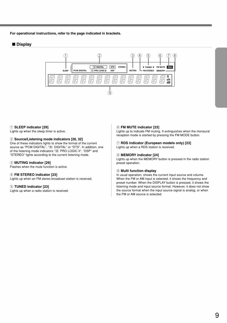
1 SLEEP indicator [29]Lights up when the sleep timer is active.
2 Source/Listening mode indicators [26, 32]One of these indicators lights to show the format of the currentsource as “PCM DIGITAL”, “Ÿ DIGITAL” or “DTS”. In addition, oneof the listening mode indicators “Ÿ PRO LOGIC II”, “DSP” and“STEREO” lights according to the current listening mode.
3 MUTING indicator [29]Flashes when the mute function is active.
4 FM STEREO indicator [23]Lights up when an FM stereo broadcast station is received.
5 TUNED indicator [23]Lights up when a radio station is received.
RDS
1 2
9
3 4 5 6 7 8
6 FM MUTE indicator [23]Lights up to indicate FM muting. It extinguishes when the monauralreception mode is started by pressing the FM MODE button.
7 RDS indicator (European models only) [23]Lights up when a RDS station is received.
8 MEMORY indicator [24]Lights up when the MEMORY button is pressed in the radio stationpreset operation.
9 Multi function displayIn usual operation, shows the current input source and volume.When the FM or AM input is selected, it shows the frequency andpreset number. When the DISPLAY button is pressed, it shows thelistening mode and input source format. However, it does not showthe source format when the input source signal is analog, or whenthe FM or AM source is selected.
For operational instructions, refer to the page indicated in brackets.
Display

10
SN 29343138 TX-L5.E
Index to Parts and Controls
For operational instructions, refer to the page indicated in brackets.
Rear panel
R LFRONT SPEAKERSSURROUND
SPEAKERSCENTER
SPEAKERR L
ANTENNA
AM FM 75
REMOTECONTROL
S VIDEO
SUBWOOFER
PRE OUT
MON OUT
VIDEOIN IN OUT ININOUT IN IN
DVD/CDMONOUT
DVD/CD
L
R
IN
AUDIO
VIDEO 1 VIDEO 2 MD/TAPE
OUT INOUT INOUT ININ
HDDVD/CD
L
R
VIDEO 1 VIDEO 2 VIDEO 2VIDEO 1 DIGITAL INPUT
(OPTICAL)
(COAXIAL)VIDEO 2
DVD
HD(OPTICAL)
AV RECEIVERMODEL NO. TX-L5
1 2 43 5 6 7 8
9 0
1 VIDEO (DVD/CD IN / VIDEO 1 OUT/IN / VIDEO 2 IN) [13]There are 3 video inputs and 1 output. Connect DVD players, LDplayers, VCRs or other video components to the video inputs. Thevideo output channel can be used to be connected to video taperecorder for making recordings.
2 MON OUT [12]The monitor output includes both RCA type and S videoconfigurations. This output is for connecting television monitors orprojectors.
3 S VIDEO (DVD/CD IN / VIDEO 1 OUT/IN / VIDEO 2 IN)[13]
There are 3 video inputs and 1 output. Connect DVD players, LDplayers, VCRs or other video components to the video inputs. Thevideo output channel can be used to be connected to video taperecorder for making recordings.
4 z (REMOTE CONTROL) [18]Connect the Onkyo components that have z connectors such as aCD player, and cassette tape deck using the z cables providedwith them. When these components are interconnected, they can becontrolled from the remote controller provided with the TX-L5.After connecting the z connectors, check the operation of theremote controller buttons for use in controlling other components(refer to page 27).• The z connectors are only effective if they are used in
conjunction with an Onkyo amplifier with an z connector. Do notconnect to a component other than Onkyo component with an zconnector. Doing so may damage the TX-L5.
• Connecting z cable only does not make the system operational.You must also connect the audio cables as well.
• If the connected component has two z connectors, you can useeither one to connect to the TX-L5. The other one can be used todaisy chain with another component.
5 SUB WOOFER PRE OUT [15]This terminal is for connecting an active subwoofer.
6 DIGITAL INPUT (DVD, HD (OPTICAL), VIDEO 2 (COAXIAL))[12, 13]
These are the digital audio inputs. There are 2 digital inputs withoptical jacks and 1 with a coaxial jack. The inputs accept digitalaudio signals from DVD players, hard disk recorders, CD players, orother digital source component.
7 SURROUND SPEAKERS L/R, CENTER SPEAKER [15]Speaker terminals are provided for the center, surround left andsurround right speakers.
8 FRONT SPEAKERS L/R [15]Speaker terminals are provided for the front left, front right speakers.Speaker outputs are compatible with banana plug connectors (otherthan European models).
9 AUDIO L/R (DVD/CD IN / VIDEO 1 OUT/IN / VIDEO 2 IN /HD OUT/IN / MD/TAPE OUT/IN) [12, 13]
These are the analog audio inputs and outputs. There are 5 audioinputs and 3 audio outputs. The audio inputs and outputs requireRCA type connectors.When connecting a VCR or other video component, make sure youconnect the audio and video leads together (i.e., both to VIDEO 1).
0 ANTENNA [16, 17]These terminals are for connecting the FM antenna and AMantenna.
11
SN 29343138 TX-L5.E
For operational instructions, refer to the page indicated in brackets.
Remote Controller
DISPLAYVIDEO 2VIDEO 1DVD/CD
DIMMER
HD TUNERMD/TAPE
DVD MD
STANDBYON
MENUTOP MENU
SETUP
SURR MODE
TEST TONE
DISTANCE LATE NIGHT A.CTRL MUTING
VOLUME
CH SEL
STEREO SP SETUP SW MODE
RETURN
REMOTE CONTROLLER RC-453S
PRESET
PLAY
SLEEP
INPUT SELECTOR
DVD MDControl
ENTER
9
0
8
7
6
5
3
4
2
1
=
~!@
-
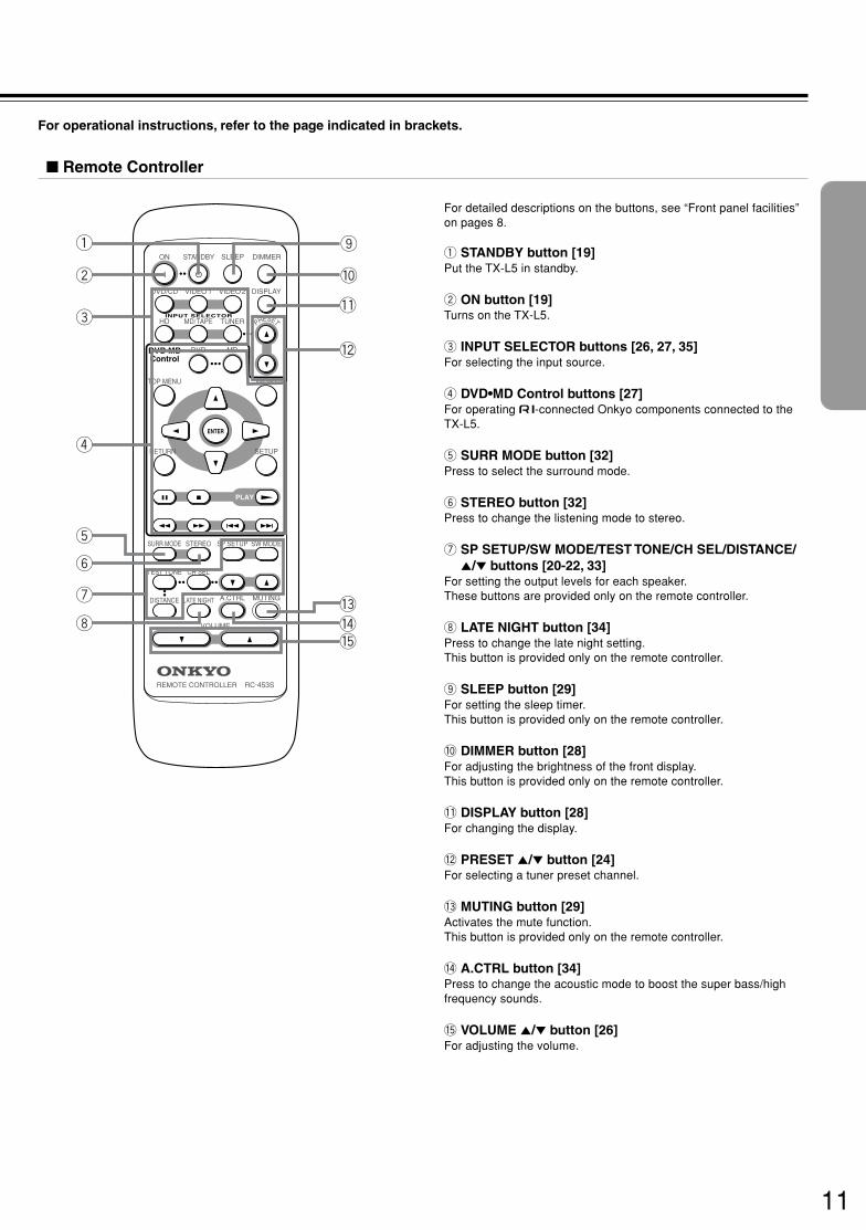
For detailed descriptions on the buttons, see “Front panel facilities”on pages 8.
1 STANDBY button [19]Put the TX-L5 in standby.
2 ON button [19]Turns on the TX-L5.
3 INPUT SELECTOR buttons [26, 27, 35]For selecting the input source.
4 DVD•MD Control buttons [27]For operating z-connected Onkyo components connected to theTX-L5.
5 SURR MODE button [32]Press to select the surround mode.
6 STEREO button [32]Press to change the listening mode to stereo.
7 SP SETUP/SW MODE/TEST TONE/CH SEL/DISTANCE/5/∞ buttons [20-22, 33]
For setting the output levels for each speaker.These buttons are provided only on the remote controller.
8 LATE NIGHT button [34]Press to change the late night setting.This button is provided only on the remote controller.
9 SLEEP button [29]For setting the sleep timer.This button is provided only on the remote controller.
0 DIMMER button [28]For adjusting the brightness of the front display.This button is provided only on the remote controller.
- DISPLAY button [28]For changing the display.
= PRESET 5/∞ button [24]For selecting a tuner preset channel.
~ MUTING button [29]Activates the mute function.This button is provided only on the remote controller.
! A.CTRL button [34]Press to change the acoustic mode to boost the super bass/highfrequency sounds.
@ VOLUME 5/∞ button [26]For adjusting the volume.

12
SN 29343138 TX-L5.E
Connecting to Audio/Video EquipmentBefore connecting• Refer also to the instruction manual of each component to be
connected.• When you connect the AV Receiver to audio/video equipment, be
sure to turn off the power and unplug all the units from the mainsbefore making any connections.
• About DIGITAL INPUT (OPTICAL) jackRemove the protective caps before makingconnections. When not in use, be sure to replacethem.
R LFRONT SPEAKERSSURROUND
SPEAKERSCENTER
SPEAKERR L
ANTENNA
AM FM 75
REMOTECONTROL
S VIDEO
SUBWOOFER
PRE OUT
MON OUT
VIDEOIN IN OUT ININOUT IN IN
DVD/CDMONOUT
DVD/CD
L
R
IN
AUDIO
VIDEO 1 VIDEO 2 MD/TAPE
OUT INOUT INOUT ININ
HDDVD/CD
L
R
VIDEO 1 VIDEO 2 VIDEO 2VIDEO 1
AV RECEIVERTX-L5
DIGITAL INPUT
(OPTICAL)
(COAXIAL)VIDEO 2
DVD
HD(OPTICAL)
DIGITAL OUT
OPTICAL
AUDIO OUT (PLAY)
R LAUDIO IN
(REC)
R LAUDIO OUT
(PLAY)
R LAUDIO IN
(REC)
R L
S VIDEO IN
VIDEO IN
Audio connection cable (Analog signal)
Optical cable (Digital signal)
Audio (L)
Optical plug
Signal flow
Audio (R)
Cassette Tape deck, MD recorder,DAT deck, CD recorder (MD/TAPE)
Digital audio processor,Hard disk recorder etc. (HD)
TV monitor or Projector(MON OUT)
S video connection cable (S videosignal)
S video plug
Example of monitor and audio equipmentconnections
Video connection cable (Analog signal)VIDEO
DO NOT connect thepower cord (mailnslead) at this time.
• Connect the plugs securely. • About the DVD, VIDEO 1 and VIDEO 2
jacksThe video input/output connections are alsonecessary even if you make the S videoinput/output connections.
Incomplete
Insert completely
NoteThe signal that comes in fromS VIDEO IN is sent to S VIDEOOUT. The signal that comes in fromVIDEO IN is sent to VIDEO OUT.

13
SN 29343138 TX-L5.E
R LFRONT SPEAKERSSURROUND
SPEAKERSCENTER
SPEAKERR L
ANTENNA
AM FM 75
REMOTECONTROL
S VIDEO
SUBWOOFER
PRE OUT
MON OUT
VIDEOIN IN OUT ININOUT IN IN
DVD/CDMONOUT
DVD/CD
L
R
IN
AUDIO
VIDEO 1 VIDEO 2 MD/TAPE
OUT INOUT INOUT ININ
HDDVD/CD
L
R
VIDEO 1 VIDEO 2 VIDEO 2VIDEO 1
AV RECEIVERTX-L5
DIGITAL INPUT
(OPTICAL)
(COAXIAL)VIDEO 2
DVD
HD(OPTICAL)
LR
S VIDEO OUT
VIDEO OUT
AUDIO OUT
S VIDEO OUT
VIDEO IN
AUDIO OUT
R L R L
VIDEO OUT
AUDIO IN
S VIDEO IN
LR
S VIDEO OUT
VIDEO OUT
AUDIO OUT
DIGITAL OUT
OPTICAL
DIGITAL OUT
COAXIAL
DVD player, CD player orLD player* (DVD/CD)
Satellite tuner etc.(VIDEO 2)
VCR (VIDEO 1)
Audio/video connection cable
S video cable (S video signal)
Coaxial cable (Digital signal)
Video
Audio (L)
Audio (R)
Coaxial plug
Signal flow
S video plug
Optical cable (Digital signal)
Optical plug
Example of video equipment connections
DO NOT connect thepower cord (mailnslead) at this time.
* If you have an LD player with AC-3RFoutput, connect via an AC-3RFdemodulator to one of the TX-L5’sDIGITAL INPUT terminals.

1414
SN 29343138 TX-L5.E
Positioning SpeakersThe front left, center, and right speakers, surround left and right speakers, and subwoofer can be connected to the AVreceiver.You can reproduce the sounds such as Dolby surround and DTS surround.
Standard speaker placementSpeaker placement plays an important role in the reproduction of Surround sound.The placement of the speakers varies depending on the size of the room and the wall coverings used in the room. Theillustration below shows an example of a layout for standard speaker placement. Refer to this example when you positionthe speakers in order to experience the best of Surround sound.For ideal Surround effects, all speakers should be installed.If a center speaker or subwoofer is not connected, the sound from the unused channel is properly distributed to theconnected speakers in order to reproduce the best Surround sound possible.
FrontThe center speaker reproduces a richer sound image by enhancing the perception of the sound's source and movement.The left, right, and center speakers should face the seated listener and be placed at ear level.
SurroundThe surround speakers reproduce the feel of a moving sound while creating the sensation of being in the middle of the action.Place the left and right surround speakers 1 meter (3 feet) above the listener's ear level and facing toward the sides of the room, making surethat the listener is within the speakers' dispersion angle.
SubwooferInstall a subwoofer with a built-in power amplifier for powerful bass sounds.The placement of the subwoofer does not affect the final quality of the sound imagemuch, therefore, you can install it wherever it is convenient.
Refer to the speakers’ instruction manuals for details.
TV/Screen
FrontCenter
Speaker
FrontrightSpeaker
Front
left
SpeakerSub-
woofer
Surroundleft
Speaker
Surroundright
Speaker

1515
SN 29343138 TX-L5.E
Connecting SpeakersBefore connecting• Refer also to the instruction manuals of the speakers.• Be sure to connect the positive and negative cables for the
speakers properly. If they are mixed up, the left and right signalswill be reversed and the audio will sound unnatural.
• Connect speakers with an impedance between 6 Ω and 16 ΩConnecting speakers with an impedance less than 6 Ω maydamage the TX-L5.
• To prevent damage to circuits, never short-circuit the positive (+)and negative (–) speaker wires.
Connecting to SPEAKER terminals
+
–
+
–
LR
+
–
+
–
LR
DIGITAL INPUT
(OPTICAL)
(COAXIAL)VIDEO 2
DVD
HD(OPTICAL)
R LFRONT SPEAKERSSURROUND
SPEAKERSCENTER
SPEAKERR L
ANTENNA
AM FM 75
REMOTECONTROL
S VIDEO
SUBWOOFER
PRE OUT
MON OUT
VIDEOIN IN OUT ININOUT IN IN
DVD/CDMONOUT
DVD/CD
L
R
IN
AUDIO
VIDEO 1 VIDEO 2 MD/TAPE
OUT INOUT INOUT ININ
HDDVD/CD
L
R
VIDEO 1 VIDEO 2 VIDEO 2VIDEO 1
AV RECEIVERTX-L5
+–+–
+– +–
+–
Right ch.
Center speaker
SurroundspeakerRight ch.
Left ch.
DO NOT connect thepower cord (mainslead) at this time.
SurroundspeakerLeft ch.
Activesubwoofer
– Front speakers –
How to connect to the FRONT SPEAKERS teminals
Loosen thescrew.
Fully insert theend of thecable.
Tighten thescrew.
• Do not connect more than one speaker cable to onespeakerterminal. Doing so may damage the TX-L5.
• When you are using only one speaker or when you wish to listento monaural (mono) sound, a single speaker should never beconnected in parallel to both the right and left channel terminalssimultaneously.
NO!
NO!NO!
Press and holdthe lever.
Insert the strippedend of the cable.By releasing thelever, the lever isreplaced.
How to connect to the SURROUND SPEAKERS andCENTER SPEAKER terminals15 mm (5/8”)
10 mm (3/8”)
Strip 15 mm (5/8”) from the end of eachcable, then twist the exposed wires tightly.
Strip 10 mm (5/8”)from the end ofeach cable, thentwist the exposedwires tightly.

1616
SN 29343138 TX-L5.E
R LFRONT SPEAKERSSURROUND
SPEAKERSCENTER
SPEAKERR L
ANTENNA
AM FM 75
REMOTECONTROL
S VIDEO
SUBWOOFER
PRE OUT
MON OUT
VIDEOIN IN OUT ININOUT IN IN
DVD/CDMONOUT
DVD/CD
L
R
IN
AUDIO
VIDEO 1 VIDEO 2 MD/TAPE
OUT INOUT INOUT ININ
HDDVD/CD
L
R
VIDEO 1 VIDEO 2 VIDEO 2VIDEO 1
AV RECEIVERTX-L5
DIGITAL INPUT
(OPTICAL)
(COAXIAL)VIDEO 2
DVD
HD(OPTICAL)
Connecting the Supplied FM and AM Indoor Antennas (Aerials)
Making Antenna (Aerial) Connections
DO NOT connect thepower cord (mainslead) at this time.
FM indoorantenna (aerial)
Adjusting the position of the FM indoor antenna (aerial)The FM indoor antenna is for indoor use only. During use, extend the antenna and moveit in various directions until the clearest signal is received. Fix it with push pins or similarimplements in the position that will cause the least amount of distortion.If the reception is not very clear with the attached FM indoor antenna, the use of anoutdoor antenna is recommended.
ANTENNA
AM FM 75
North American models:1 Strip away the insulation from the end of the cord.
2 Fully insert the stripped end of the cord.
Except for North American models:Fully insert the end of the cord.
Adjusting the position of the AM indoor antenna (aerial)The AM loop antenna is for indoor use only. Set it in the direction and position where youreceive signals clearly. Put it as far away as possible from the TX-L5, televisions, speakercables, and power cords.When reception is not satisfactory with the attached AM loop antenna alone, connection ofan outdoor antenna is recommended.
AM indoor antenna(aerial)
ANTENNA
AM FM 75
Insert into thehole.
Rotate the outer frameof the antenna.
Extend theantenna cord.
Press up and holdthe lever.
Insert the end of thecord.
Release the lever tosecure the connection.
NoteInsert one end of the AMantenna (aerial) cord to eitherof the AM antenna (aerial)connectors and the other endto the other connector. Thereis no difference between oneend of the AM antenna(aerial) cord and the otherend, unlike the speakercables which have positiveand negative poles.

1717
SN 29343138 TX-L5.E
ANTENNA
AM FM 75
Connecting an FM Outdoor Antenna (Aerial)If the FM reception is not very clear with the supplied antenna (aerial), connect an FM outdoor antenna (aerial) instead ofthe indoor FM antenna (aerial).
Notes• Install the antenna (aerial) well away from tall buildings and in an area where FM stations can directly be received.• Keep the antenna (aerial) away from noise sources (neon signs, busy roads, etc.).• It is dangerous to put the antenna (aerial) close to power lines. Keep it well away from power lines, transformers, etc.• To avoid the risk of lightning and electrical shock, grounding is necessary. Follow item 14 of the "Important Safeguards" on page 2 when you
install the outdoor antenna (aerial).
Directional linkagetype splitter
To AV Receiver To TV (or VCR)
FM outdoor antenna (aerial)
Connecting 300 ohm ribbonwire to a 75/300 ohmantenna (aerial) adapter*Loosen the screws and wrapthe wire around these screws.Then tighten the screws witha screwdriver.
Tighten
Loosen
Connecting coaxial cable to a 75/300 ohm antenna (aerial) adapter*
3 Remove the transformer wire Afrom slit B and insert it into slit C.
4 Insert the end of the cable.5 Clamp it in place with pliers.
6 Reinstall the cover.
4
5
1 Strip the end of the coaxial cable.
2 With your fingernail or a smallscrewdriver, press the stoppersoutward and remove the cover.
Slit B
Slit C
Wire A
15 mm3
mm
6mm
6mm
5/8 in.
1/8in.
1/4in.
1/4in.
* (European, USA andCanadian models)Not supplied
(Other models)Supplied
Directional IinkageDo not use the same antenna (aerial) for both FM and TV (or VCR) reception since the FM and TV (or VCR) signals can interferewith each other. If you must use a common FM/TV (or VCR) antenna (aerial), use a directional linkage type splitter.
Connecting an AM Outdoor Antenna (Aerial)
AM indoor antenna(aerial)
Outdoor antenna (aerial)
ANTENNA
AM FM 75
An outdoor antenna (aerial) will be more effective if it isstretched horizontally above a window or outside.Leave the supplied AM indoor antenna (aerial) connected.
NoteTo avoid the risk of lightning and electrical shock, grounding isnecessary. Follow item 14 of the "Important Safeguards" on page 2when you install an outdoor antenna (aerial).

1818
SN 29343138 TX-L5.E
Connections for remote control (z)
Incomplete
• Connect the cassette tape deck to the MD/TAPE jacks. In this case, switch the sourcefrom MD to TAPE (refer to page 27).
• Connect the CD player to the DVD/CD jacks. In this case, switch the source from DVDto CD (refer to page 27).
Notes• Do not connect the Onkyo MD recorder , CD recorder and cassette tape deck with the z cable at
the same time. This may lead to unexpected operation.• Connect the plugs securely.• Be sure to connect to the z connectors using the z cable.• The connections on pages 12 and 13 are needed even if z connection is made.• Do not connect the AV Receiver’s z connector to any component other than an Onkyo product. It
may cause malfunction.• Certain component models may not be able to control the TX-L5.
Example: Onkyo DVD Player DV-L5
Insert completely
You can use the remote controller of this receiver to operate the z-connected Onkyo DVD player, CD player, MD recorderor cassette tape deck using the z cable provided with them (refer to page 27).
z cable
Notes• When the DVD player, CD player or MD recorder connected to with the
TX-L5 through z cable is turned on, the TX-L5 automatically turns on andselects the source that was turned on. (Auto Power On)
• Turning the TX-L5 off sets the z-connected DVD player, CD player or MDrecorder to standby mode. (Auto Power Off)
• When the TX-L5 is already on, pressing the play button on the DVD player,CD player, cassette tape deck or MD recorder merely selects the inputsource that was played. (Direct Change)
R LFRONT SPEAKERSSURROUND
SPEAKERSCENTER
SPEAKERR L
ANTENNA
AM FM 75
REMOTECONTROL
S VIDEO
SUBWOOFER
PRE OUT
MON OUT
VIDEOIN IN OUT ININOUT IN IN
DVD/CDMONOUT
DVD/CD
L
R
IN
AUDIO
VIDEO 1 VIDEO 2 MD/TAPE
OUT INOUT INOUT ININ
HDDVD/CD
L
R
VIDEO 1 VIDEO 2 VIDEO 2VIDEO 1
AV RECEIVERTX-L5
DIGITAL INPUT
(OPTICAL)
(COAXIAL)VIDEO 2
DVD
HD(OPTICAL)
L
MONO
R
VIDEO OUTPUT
Y
C B
C R
OPTICAL COAXIAL
REMOTE CONTROL
REMOTE CONTROL
ANALOGOUTPUT
DIGITALOUTPUT
VIDEO S VIDEO COMPONENT
W
L
MONO
R
ANALOGOUTPUT
DO NOT connect thepower cord (mainslead) at this time.
Be sure to connect usingthe audio connectioncable.

1919
SN 29343138 TX-L5.E
Connecting the Power/Turning on the AV ReceiverBefore connecting• Make sure that all the connections from pages 10 to 16 are complete.• Turning on the AV Receiver may cause a momentary power surge, which might interfere with other electrical equipment such as computers. If
this happens, use a wall outlet on a different circuit.
3
STANDBY/ONON
STANDBY
STANDBY/ONON
STANDBY
SUBWOOFER MODESURROUND STEREO
ON
STANDBY
POWER
STANDBY / ON
ON OFF
PHONES ACOUSTICCONTROLTUNING/PRESET
DVD / C D VIDEO 1 VIDEO 2 HD MD / TAPE
FM AM
INPUT
VOLUME
AV RECEIVER TX-L5
MEMORY FM MODE
132
DISPLAYVIDEO 2VIDEO 1DVD/CD
DIMMER
HD TUNERMD/TAPE
DVD MD
STANDBYON
MENUTOP MENU
SETUP
SURR MODE
TEST TONE
DISTANCE LATE NIGHT A.CTRL MUTING
VOLUME
CH SEL
STEREO SP SETUP SW MODE
RETURN
REMOTE CONTROLLER RC-453S
PRESET
PLAY
SLEEP
INPUT SELECTOR
DVD MDControl
ENTER
3
Connect the power cord (mains lead) to a walloutlet (the mains).
2
1Press POWER switch to switch on the mainpower.The TX-L5 enters standby mode.The STANDBY indicator lights up.
Notes• The TX-L5 is shipped with the main
power ( POWER) switch in the onposition (_) ON.
• To switch off the main power, press the POWERswitch again.
• The buttons on the remote controller don’t operate ifthe POWER switch is set to OFF.
Press STANDBY/ON on the AV Receiver orON on the remote controller.The AV Receiver turns on.The ON indicator and display on theAV Receiver’s front panel light. At thesame time, the STANDBY indicatorgoes off.
Notes• When the Onkyo DVD player, CD player, MD
recorder and cassette tape deck are z-connected,pressing ON button on the remote controller turns inthe z-connected components.
• To turn off the AV Receiver, press STANDBY/ONon the AV Receiver, or STANDBY on the remotecontroller. The AV Receiver enters standby mode. Besure to set the volume to minimum before turning offthe AV receiver.
The shape may differdepending on the region.

20
SN 29343138 TX-L5.E
You need to setup the speaker configuration for thespeaker system connected to the SPEAKER teminals.It is not necessary to set the parameters again once youhave completed the setup unless you change the speakerconfiguration.
NoteSpeakers setup cannot be done if headphones are connected.
Speaker Setup
Selecting the number of speakerchannels
Press SP SETUP repeatedly toselect the number of channelswithin 3 seconds.
The normal display resumes in 3 seconds
Notes• The listening mode will automatically
change according to the number ofchannels if you set the number of channels.
• With the first press of SP SETUP, you cancheck the present setting. Then each pressof the button changes the number ofchannels.
Display and number of speaker channels
SP SETUP
Speaker 5ch
Speaker 2ch
Speaker 3ch
Speaker 4ch
Front left Front rightCenter
Surround left Surroundright
DISPLAYVIDEO 2VIDEO 1DVD/CD
DIMMER
HD TUNERMD/TAPE
DVD MD
STANDBYON
MENUTOP MENU
SETUP
SURR MODE
TEST TONE
DISTANCE LATE NIGHT A.CTRL MUTING
VOLUME
CH SEL
STEREO SP SETUP SW MODE
RETURN
REMOTE CONTROLLER RC-453S
PRESET
PLAY
SLEEP
INPUT SELECTOR
DVD MDControl
ENTER
SW MODE
SP SETUP
SUBWOOFER MODE
SW MODE
Setting the Subwoofer Mode
Press SUBWOOFER MODE on theunit or SW MODE on the remotecontroller.
With the first press of the button, you cancheck the present setting. Then eachpress of the button changes the subwoofermode as follows (a tip on how to select theright subwoofer mode is in parentheses):
→ SUBWOOFER OFF
(When no subwoofer is connected)
↓SUBWOOFER MODE 1
(When you want to enhance the superbass)
↓SUBWOOFER MODE 2
(When you want to lower the superbass)
The normal display resumes in threeseconds.
Unit
Remote controller
SUBWOOFER MODESURROUND STEREO
ON
STANDBY
POWER
STANDBY / ON
ON OFF
PHONES ACOUSTICCONTROLTUNING/PRESET
DVD / C D VIDEO 1 VIDEO 2 HD MD / TAPE
FM AM
INPUT
VOLUME
AV RECEIVER TX-L5
MEMORY FM MODE
SUBWOOFER MODE

21
SN 29343138 TX-L5.E
Before starting the procedure below, measure thedistances from each speaker to the listening position.For pair speakers such as front left and right speakers,the distance from the listening position to one speakershould be the same as the distance to the other.In the procedure below, select the values whichapproximate the actual distances.
1 Press CH SEL, then press 5/∞repeatedly to select the surroundleft and right speaker distance.
You cannot enter the following distances:
• Distances longer than the distance setfor the front speakers.
• Distances shorter than the distanceobtained by subtracting “4.5 m (15 ft.)”from the distance entered for the frontspeakers.
NoteIf you selected a speaker configuration with nosurround speakers on the previous page, thisstep will be skipped.
Press DISTANCE.The normal display resumes.
2
4
35
DISPLAYVIDEO 2VIDEO 1DVD/CD
DIMMER
HD TUNERMD/TAPE
DVD MD
STANDBYON
MENUTOP MENU
SETUP
SURR MODE
TEST TONE
DISTANCE LATE NIGHT A.CTRL MUTING
VOLUME
CH SEL
STEREO SP SETUP SW MODE
RETURN
REMOTE CONTROLLER RC-453S
PRESET
PLAY
SLEEP
INPUT SELECTOR
DVD MDControl
ENTER
1, 53, 4 2-4
DISTANCE
CH SEL
«
CH SEL
«
DISTANCE
Press DISTANCE.The distance entry display for the front leftand right speakers appears.
Press 5/∞ to select the front leftand right speaker distance.You can select a distance between 0.3 mand 9 m (1 ft. and 30 ft.).
Press CH SEL, then press 5/∞repeatedly to select the centerspeaker distance.
You cannot enter the following distances:
• Distances longer than the distance setfor the front speakers.
• Distances shorter than the distanceobtained by subtracting “1.5 m (5 ft.)”from the distance entered for the frontspeakers.
NoteIf you selected a speaker configuration with nocenter speaker on the previous page, this stepwill be skipped.
Setting the Distance From the Listening Position to Each Speaker

22
SN 29343138 TX-L5.E
Speaker Setup
Adjust each speaker’s relative volume balance so that thevolumes of all speakers’ test tones sound equal at thelistening position.
NoteYou cannot adjust the volume balance while the muting function isactivated.
Press TEST TONE.Each speaker emits the test tone (pinknoise) and the display shows the speakeremitting the test tone in the followingorder:
LEFT → CENTER
(Front left) (Center)
↑ ↓SUBWOOFER RIGHT
(Subwoofer) (Front right)
↑ ↓SURR LEFT ← SURR RIGHT
(Surround left) (Surround right)
Notes• No test tone will be emitted from the
speaker which is not included in thespeaker configuration on page 20 even if itis actually connected.
• No test tone will be emitted from thesubwoofer when the subwoofer mode is setto “SUBWOOFER OFF”.
1 2
3
Press CH SEL repeatedly to selectthe speaker, then press 5/∞ toadjust the volume level.The volume level can be adjusted between–12dB and +12dB.
When you have completed theadjustment by repeating step 2,press TEST TONE.The test tone stops and the normal displayresumes.
NoteEven if you don’t press TEST TONE, the testtone will stop after 2 minutes.
TEST TONE CH SEL
«
TEST TONE
Adjusting Each Speaker's Relative Volume Balance – Test Tone
DISPLAYVIDEO 2VIDEO 1DVD/CD
DIMMER
HD TUNERMD/TAPE
DVD MD
STANDBYON
MENUTOP MENU
SETUP
SURR MODE
TEST TONE
DISTANCE LATE NIGHT A.CTRL MUTING
VOLUME
CH SEL
STEREO SP SETUP SW MODE
RETURN
REMOTE CONTROLLER RC-453S
PRESET
PLAY
SLEEP
INPUT SELECTOR
DVD MDControl
ENTER
21, 32

23
SN 29343138 TX-L5.E
There are two ways to select radio stations:• Manual tuning• Presetting radio stations then selecting the preset
channels
Listening to the Radio
Tuning Manually
Turn INPUT dial to select the band(FM or AM).
e.g. When FM is selected.
Turn VOLUME dial to adjust thevolume.
Press and hold TUNING/PRESET™/£ for about 1.5 seconds.
When the band is FMAuto tuning starts. The frequency changes in50 kHz steps.When a broadcast is received, scanning stopsand the frequency flashes in the display.
When the band is AMThe frequency changes as follows:– (USA and Canadian models)
In 10 kHz steps– (Other models)
In 9 kHz stepsWhen you release the button, the frequencystops changing and flashes in the display.
NoteIf you press and hold TUNING/PRESET ™/£short time, the AV receiver enters the selectingpreset stations mode. Refer to “SelectingPreset Stations” on page 24.
1
2
Appears when a broadcast is received.
4
Tuning in a weak frequency (only for FMstations)
When you tune in a stereo FM station, the FM STEREOindicator lights up if the signal is sufficiently strong.
If the signal is weak, you may not be able to tune to thestation. In this case, press FM MODE. The FM MUTEindicator goes off.Then select the station to which you want to listen.(At this time, the station will be in mono and interstation noisewill be heard.)
INPUT
VOLUME
TUNING/PRESET
TUNING/PRESET
FM MODE
3
Receiving RDS (European models only)When an Radio Data System (RDS) station broadcastingProgram Service Name (PS) information is received, the RDSindicator lights up and the name of the station is displayed.• RDS reception is only available on the European models,
and only in areas where RDS broadcasts are available.
While the frequency is flashing (forabout 3 seconds), press TUNING/PRESET ™/£ to change thefrequency.• The frequency changes each time you
press TUNING/PRESET ™/£.
• You can change the frequency as longas the frequency in the display isflashing. Each press of either buttoncauses the frequency to flash for about3 seconds.
The corresponding indicatoris lit while the input sourceis FM or AM.
VOLUMEdial
INPUT dial
SUBWOOFER MODESURROUND STEREO
ON
STANDBY
POWER
STANDBY / ON
ON OFF
PHONES ACOUSTICCONTROLTUNING/PRESET
DVD / C D VIDEO 1 VIDEO 2 HD MD / TAPE
FM AM
INPUT
VOLUME
AV RECEIVER TX-L5
MEMORY FM MODE
TUNING/PRESET ™/£
FM MODE
RDS

24
SN 29343138 TX-L5.E
Selecting Preset StationsBefore selecting preset stations, you need to preset the radiostations. See “Presetting Radio Stations” on the left column ofthis page.
Press TUNER on the remotecontroller or rotate the INPUT dialon the unit to switch the inputsource to the tuner.“FM” or “AM” appears in the display.
The band selected in this step will notaffect the next step.
Press PRESET 5/∞ on the remotecontroller or TUNING/PRESET™/£ on the unit repeatedly toselect the preset number of thedesired radio station.
NoteIf you press TUNING/PRESET ™/£ on theunit for more than 1.5 seconds, the unit entersthe manual tuning mode. See step 2 in “TuningManually” on the previous page.
1
2
Unit
SUBWOOFER MODESURROUND STEREO
ON
STANDBY
POWER
STANDBY / ON
ON OFF
PHONES ACOUSTICCONTROLTUNING/PRESET
DVD / C D VIDEO 1 VIDEO 2 HD MD / TAPE
FM AM
INPUT
VOLUME
AV RECEIVER TX-L5
MEMORY FM MODE
TUNING/PRESET ™/£MEMORY
FM MODE
INPUT
PRESET
TUNING/PRESET
DISPLAYVIDEO 2VIDEO 1DVD/CD
DIMMER
HD TUNERMD/TAPE
DVD MD
STANDBYON
MENUTOP MENU
SETUP
SURR MODE
TEST TONE
DISTANCE LATE NIGHT A.CTRL MUTING
CH SEL
STEREO SP SETUP SW MODE
RETURN
PRESET
PLAY
SLEEP
INPUT SELECTOR
DVD MDControl
ENTER
TUNER
PRESET 5/∞
TUNER
Presetting Radio StationsYou can preset up to 30 stations.
Tune in the radio station you wishto preset (refer to the previouspage).
Press MEMORY.The MEMORY indicator lights and thepreset number starts flashing in thedisplay.
While the MEMORY indicator is lit(for about 8 seconds), pressTUNING/PRESET ™/£ to selectthe preset number.
Press MEMORY.The radio station is registered to the presetchannel.
To register another preset station, repeatsteps 1 to 4.
NoteWhen you preset either FM station or AM station only, you cannotswitch the band to another band (for example AM to FM) with theremote controller. Turn INPUT dial to select the band.
1
2
3
4
MEMORY
TUNING/PRESET
MEMORY
INPUT dial
Remotecontroller
Remotecontroller
Unit
Listening to the Radio

25
SN 29343138 TX-L5.E
Erasing a Preset Station
Select the preset channel you wishto erase (see steps in the previouspage).
Press FM MODE while holdingdown MEMORY.
The selected preset channel will beerased.
1
Various Functions While Listening toRadio Programs
To use the following functions, see pages 28 and 29.• Changing the Display• Controlling the Brightness of the Lights on the AV receiver• Muting the Sound• Listening Through Headphones• Using the Sleep Timer
Enjoying the Surround Modes WhileListening to Radio Programs
See page 30.
2MEMORY FM MODE

26
SN 29343138 TX-L5.E
Playing the Connected SourceThis section shows you how to play the sourcesconnected to the AV Receiver.You may need to see “Connecting to Audio/VideoEquipment” on page 12 while following the steps in thissection.
Press INPUT SELECTOR on theremote controller or turn the INPUTdial on the unit to select one of thefollowing input sources:• DVD/CD
• VIDEO 1
• VIDEO 2
• HD
• MD/TAPE
e.g. When VIDEO 1 is selected.
Press VOLUME 5/∞ on the remotecontroller or turn VOLUME dial toadjust the volume.
Start playing the selected source.
1 Remotecontroller
Unit
2
About digital soundIf the equipment is digitally connected to the AV Receiver, thesound from the digital input will automatically be selected andreproduced instead of the analog sound as explained below.• When the DVD source is selected, the digital sound from the
DVD DIGITAL INPUT (OPTICAL) connector is reproduced.• When the VIDEO 2 source is selected, the digital sound from the
VIDEO 2 DIGITAL INPUT (COAXIAL) connector is reproduced.• When the HD source is selected, the digital sound from the HD
DIGITAL INPUT (OPTICAL) connector is reproduced.
When the digital sound is reproduced, the ŸDIGITAL, DTS, or PCMDIGITAL (2 channel digital stereo) indicator lights up according tothe received sound system in the AV receiver’s display.
PCM DIGITAL Ÿ DIGITAL DTS
NoteThe AV receiver only reproduces PCM, DOLBY DIGITAL and DTSsound formats from connected equipment.
Enjoying the picture with the sound ofanother source
Play the DVD, VIDEO 1 or VIDEO 2 source and select MD/TAPE, HD, FM or AM. Then you can enjoy the picture and thesound from the selected input source at the same time.
Various Functions While Playing theConnected Source
To use the following functions, see pages 28 and 29.• Changing the Display• Controlling the Brightness of the Lights on the AV receiver• Muting the Sound• Listening Through Headphones• Using the Sleep Timer
Enjoying the Surround Modes WhilePlaying the Connected Source
See page 30.
3
SUBWOOFER MODESURROUND STEREO
ON
STANDBY
POWER
STANDBY / ON
ON OFF
PHONES ACOUSTICCONTROLTUNING/PRESET
DVD / C D VIDEO 1 VIDEO 2 HD MD / TAPE
FM AM
INPUT
VOLUME
AV RECEIVER TX-L5
MEMORY FM MODE
1
DISPLAYVIDEO 2VIDEO 1DVD/CD
HD TUNERMD/TAPE
DVD MD
MENUTOP MENU
SETUP
SURR MODE
TEST TONE
DISTANCE LATE NIGHT A.CTRL MUTING
VOLUME
CH SEL
STEREO SP SETUP SW MODE
RETURN
PRESET
PLAY
INPUT SELECTOR
DVD MDControl
ENTER
1
2
VIDEO 2VIDEO 1DVD/CD
HD MD/TAPEINPUT SELECTOR
INPUT
VOLUME
VOLUME
DVD / C D VIDEO 1 VIDEO 2 HD MD / TAPE
FM AM
Remotecontroller
Unit

27
SN 29343138 TX-L5.E
DISPLAYVIDEO 2VIDEO 1DVD/CD
DIMMER
HD TUNERMD/TAPE
DVD MD
STANDBYON
MENUTOP MENU
SETUP
SURR MODE STEREO SP SETUP SW MODE
RETURN
PRESET
PLAY
SLEEP
INPUT SELECTOR
DVD MDControl
ENTER
DISPLAYVIDEO 2VIDEO 1DVD/CD
DIMMER
HD TUNERMD/TAPE
DVD MD
STANDBYON
MENUTOP MENU
SETUP
SURR MODE STEREO SP SETUP SW MODE
RETURN
PRESET
PLAY
SLEEP
INPUT SELECTOR
DVD MDControl
ENTER
Operating the DVD player/CD player/MD recorder/Cassette Tape Deck With theSupplied Remote Controller
To operate the Onkyo DVD player/CD playerFirst, connect the DVD player or CD player to the AV Receiverwith the z cable (see page 18).When the CD player is connected to the DVD/CD jacks,switch the source (see below).Point the remote controller toward the AV Receiver when youwant to operate this equipment.
Press DVD first.
To operate the Onkyo MD recorder/cassettetape deck
First, connect the MD recorder or cassette tape deck to the AVReceiver with the z cable (see page 18).When the cassette tape deck is connected to the MD/TAPEjacks, switch the source (see below).Point the remote controller toward the AV Receiver when youwant to operate this equipment.
Press MD first.
PlayPlayPlay
Down/Up––
Fast Reverse/Fast Forward
Rewind/Fast Forward
Stop/CancelStop
PauseReverse play
Upper: MD recorderLower: Cassette tape deck
Down/Up
Top menu(DVD only)
Enter(DVD only)
Menu(DVD only)
Setup(DVD only)
5/∞/2/3(DVD only)
Return(DVD only)
Pause
Stop
DVD MD
Switch the source from MD to TAPE/Switch the source from DVD to CD
You can set the AV receiver to show “TAPE” when the MD/TAPE source is selected by pressing MD/TAPE on the remotecontroller or turning the INPUT dial on the unit. In the sameway, you can set the AV receiver to show “CD” when the DVD/CD source is selected.This setting is needed to make the z system controleffective among the Onkyo cassette tape deck, MD recorder,DVD player and CD player.
To switch the source from MD to TAPE (or from DVD toCD)1 Press MD/TAPE (or DVD/CD) to select the input source.2 Press and hold MD/TAPE (or DVD/CD) on the remote
controller until the display changes (for about 2 seconds).
To restore the displayPress and hold MD/TAPE (or DVD/CD) on the remotecontroller until the display changes (for about 2 seconds).
Fast Reverse/Fast Forward
DISPLAYVIDEO 2VIDEO 1DVD/CD
DIMMER
HD TUNERMD/TAPE
DVD MD
STANDBYON
MENUTOP MENU
SETUP
SURR MODE STEREO SP SETUP SW MODE
RETURN
PRESET
PLAY
SLEEP
INPUT SELECTOR
DVD MDControl
ENTER
DVD/CD
MD/TAPE
ex

28
SN 29343138 TX-L5.E
Various Functions Common to all the Sources
DIMMER
Changing the Display
Press DISPLAY.Each time you press DISPLAY, the screenchanges as follows:
DISPLAY
When an input source other than FM or AM is selected:Press DISPLAY once to initiate the program format display.Pressing the button again switches the display to the otherdisplay.
* If the input signal does not have a program format, then this willbe skipped. The format display returns to the previous displayafter the format display has lasted for about 5 seconds ( )
When FM or AM is selected as the input source:
FM/AM + Listeningmode
FM/AM frequency +Preset no.
Input source +Listening mode
Input source +volume
Program format*
When an RDS station broadcasting PS information issettled as the input source (European models only):Press the DISPLAY once to initiate the frequency display.Pressing the button again switches the display to the otherdisplay.
ch
ch
FM frequency +Preset no.*
FM + Listening mode
Program ServiceName + Preset no.
Controlling the Brightness of theLights on the AV Receiver
Press DIMMER.Each press of the button changes thebrightness as follows:
→1. The display becomes less bright.
↓2. The display is dimmed.
↓3. The display is dimmed, and the
indicators other than the ONindicator on the AV Receiver’s frontpanel go off.
↓4. The display becomes bright and the
indicators on the AV receiver’s frontpanel turn on.
NoteIf you connect the Onkyo DV-L5 or MD-2000 using z cable, thesecomponents also changes the brightness.
* The frequency display returns to the previous display after thefrequency display has lasted for about 5 seconds ( ).
Remotecontroller only
Remotecontroller only

29
SN 29343138 TX-L5.E
PHONES jack VOLUME dial
Muting the Sound
Press MUTING.The MUTING indicator flashes in thedisplay during the muting mode.
To restore the sound, press MUTINGagain.
NoteIf you turn off the unit during muting, and turn it on again, the soundwill be restored.
Listening Through Headphones
Connect the plug of the stereo headphones to thePHONES jack on the AV Receiver.
Notes• The speakers will not reproduce sound while headphones are
connected.• The listening mode is set to “STEREO” after connecting the
headphones to the PHONES jack. When you disconnect theheadphones, the listening mode returns to the previous mode.
ON
STANDBY
POWER
STANDBY / ON
ON OFF
PHONES
Remotecontroller only
Using the Sleep Timer
Press SLEEP.“SLEEP 90 MIN” appears in themultipurpose display for about 5 seconds,which means the AV Receiver will turn offand enter standby mode in 90 minutes.Also the SLEEP indicator is lit in thedisplay while the sleep timer is On.
Each press of the button makes theremaining time shorter by 10 minutes.
Checking the remaining timePress SLEEP while the Sleep Timer is On.The remaining time is displayed.If you press SLEEP while the remaining time is displayed, theremaining time is reduced by 10 minutes.
Canceling the Sleep TimerPress SLEEP repeatedly until the SLEEP indicator goes off.
SLEEP indicator
SUBWOOFER MODESURROUND STEREO
ON
STANDBY
POWER
STANDBY / ON
ON OFF
PHONES ACOUSTICCONTROLTUNING/PRESET
DVD / C D VIDEO 1 VIDEO 2 HD MD / TAPE
FM AM
INPUT
VOLUME
AV RECEIVER TX-L5
MEMORY FM MODE
DISPLAYVIDEO 2VIDEO 1DVD/CD
DIMMER
HD TUNERMD/TAPE
DVD MD
STANDBYON
MENUTOP MENU
SETUP
SURR MODE
TEST TONE
DISTANCE LATE NIGHT A.CTRL MUTING
VOLUME
CH SEL
STEREO SP SETUP SW MODE
RETURN
REMOTE CONTROLLER RC-453S
PRESET
PLAY
SLEEP
INPUT SELECTOR
DVD MDControl
ENTER
DIMMERSLEEPDISPLAY
MUTING
MUTING SLEEP
Remotecontroller only

30
SN 29343138 TX-L5.E
The surround sound of the AV Receiver enables you toenjoy the presence of a movie theater or concert hall inyour room.Before using any surround mode, make sure the SpeakerSetup configurations have been set (see page 20).The speaker configuration is very important for thesurround sound. See "Connecting Speakers" on page 15and "Positioning Speakers" on page 14.Following are the sound systems the AV Receiver canreproduce.
DOLBY DIGITAL Surround, DTS (DigitalTheater System) Surround
This 5.1-channel digital surround format enables you toindividually record and play five full-range (20 Hz-20 kHz)channels (left and right front, center, two surround channels)plus an LFE channel (Low Frequency Effect) for the low-rangeeffect sound. It will create a realistic sound that could beheard in the theaters and concert halls.
DOLBY DIGITALSelect this option when you play a DVD video that has a mark.
DTSSelect this option when you play a DVD player, LD, or CD that has a
mark.
DOLBY PRO LOGIC II surroundThis is a 5-channel surround system of a new generation,casting a bridge between the previous 4-channel (Left/RightFront, Center and monaural surround channels) Pro Logicsurround and 5.1-channel Dolby Digital surround. Dolby ProLogic II provides the MOVIE mode optimized for viewingmovies and the MUSIC mode optimized for listening to music.In the MOVIE mode, the surround channel, which has beenmonaural and based on narrow band, is reproduced in stereoso that the feeling of movement in the played movies is moreenhanced. In the MUSIC mode, the surround channelreproduces natural sound field even with 2-channel musicsources.The MOVIE mode allows you to enjoy VHS and DVD softwarecarrying the marking as well as some of TVbroadcast programs. The MUSIC mode allows you to enjoystereo music from CD, etc.
Analog/PCM (Pulse Code Modulation)surround
Analog sources include the audio records, AM/FMbroadcasting and cassette tapes. The PCM (Pulse CodeModulation) signal is a kind of digital audio signal, which isrecorded directly on CD or DVD without being compressed.When an analog or PCM source is played, you can enjoyunique surround modes to Onkyo as listed below.
ORCHESTRAThis mode is suitable for classical and opera music. The centerchannel is cut and the surround channels are emphasized to widenthe stereo image. It simulates a natural reverberation as created in alarge hall.
UNPLUGGEDThis mode is suitable for acoustic instrumental sounds, vocals, andjazz music. By emphasizing the front stereo image, it simulates theacoustics in front of the stage.
STUDIO-MIXThis mode is suitable for rock and popular music. Lively sounds witha powerful acoustic image will make you feel as if you are in a club.
TV LOGICThis mode offers the realistic acoustics of a TV program being airedin the TV studio. It enhances the entire surround sound and clarity ofconversation.
ALL CH ST (All Channel Stereo)This mode is useful for background music. The front and surroundchannels will create a stereo image.
Enjoying the Surround Modes

31
SN 29343138 TX-L5.E
*1 Only STEREO can be selected when SP SETUP is set to 2 ch or when headphones are used.*2 These modes cannot be selected when SP SETUP is set to 2 ch or 3 ch.*3 Only STEREO can be selected when the PCM source has been recorded with a sampling rate 96 kHz.*4 Only DOLBY D (PL II if the source is a 2-channel source) or STEREO can be selected when Dolby Digital
surround audio is reproduced.*5 If you have an LD player with AC-RF output, connect it via a AC-RF demodulator to one of the TX-L5’s DIGITAL
INPUT terminals.
Notes on DTS• If you play a CD or LD that supports DTS, you may hear a noise
for a short while until the DTS decoder recognizes the DTSencoded signal and starts operating. This is not a malfunction.
• If you press the pause or skip button on the player while playinga DTS source, a short noise may be heard. This is not amalfunction.
• The DTS indicator on the TX-L5 lights up while it plays the DTSsource. When playback concludes and the DTS signaltransmission stops, the TX-L5 remains in DTS mode and theDTS indicator remains lit. This prevents noise when you operatethe pause or skip button on the player. Therefore, if the sourceswitches from the DTS signal to the PCM signal immediately, thePCM signal may not be played. In this case, stop the playback ofthe source on the player for about 3 seconds, then resumeplayback.
• Some CD players and LD players may be unable to play DTSsources correctly even if you connect the player to theTX-L5 digitally. This is because the digital signal has beenprocessed (such as the output level, sampling frequency,frequency response, etc.), and the TX-L5 cannot recognize thesignal as DTS data. Therefore, you may hear noise when youplay a DTS source while processing the signal.
• The MD/TAPE OUT, HD OUT or VIDEO 1 OUT jacks of theTX-L5 output analog audio. Do not record CDs or LDs thatsupport DTS using these jacks. Otherwise, you will record a DTSencoded signal as noise.
Relationship between input sources and surround modesThe surround modes that can be selected are variable depending on the signal formats employed with the input sources.
STEREO*1
DOLBY D
DTS
PL II MOVIE
PL II MUSIC
ORCHESTRA
UNPLUGGED
STUDIO-MIX
TV LOGIC
ALL CH STEREO
Cassette tapeAudio CDVideo CDRecord
FMAM
HD recorder
Video DVD
LD*5
Listening mode
Analog/PCM*3Dolby Digital*4
DTS
source software
Input source signal format
Video DVD
LD*5
Video DVD
Audio CD
LD
2-channel source
Surround mode
Onkyo’ssurroundmode*2
other source

32
SN 29343138 TX-L5.E
Press STEREO.In the display, “STEREO” appears and theSTEREO indicator lights up.
Unit
Remote controller
Using Dolby Pro Logic II/Onkyo’s Original DSP Modes
See “Relationship between input sources and surroundmodes” on page 31.
Press SURR MODE on the remotecontroller or SURROUND on theunit to choose “PL II” or the DSPmode.The current listening mode appears in thedisplay when the button is pressed once,then each press of the button changes thelistening mode as follows:
PL II MOVIE → PL II MUSIC
↑ ↓ALL CH ST ORCHESTRA
↑ ↓TV LOGIC UNPLUGGED
↑ ↓STUDIO-MIX
About Dolby Pro Logic II• Suitable for Dolby Surround sources.• In the display, “PL II MOVIE” or “PL II
MUSIC” appears and the Ÿ PRO LOGIC IIindicator lights up.
• Skipped if “SPEAKER 2 ch” is selected onpage 20.
Enjoying the Surround Modes
DSP indicator
Remote controller
Unit
STEREO indicator
Changing the Sound to Stereo
Ÿ PRO LOGIC II indicator
SUBWOOFER MODESURROUND STEREO
ON
STANDBY
POWER
STANDBY / ON
ON OFF
PHONES ACOUSTICCONTROLTUNING/PRESET
DVD / C D VIDEO 1 VIDEO 2 HD MD / TAPE
FM AM
INPUT
VOLUME
AV RECEIVER TX-L5
MEMORY FM MODE
SURROUND STEREO
DISPLAYVIDEO 2VIDEO 1DVD/CD
DIMMER
HD TUNERMD/TAPE
DVD MD
STANDBYON
MENUTOP MENU
SETUP
SURR MODE
TEST TONE
DISTANCE LATE NIGHT A.CTRL MUTING
VOLUME
CH SEL
STEREO SP SETUP SW MODE
RETURN
REMOTE CONTROLLER RC-453S
PRESET
PLAY
SLEEP
INPUT SELECTOR
DVD MDControl
ENTER
SURR MODE
STEREO
SURR MODE
SURROUND
STEREO
STEREO

33
SN 29343138 TX-L5.E
Adjusting Each Speaker's Relative Volume Balance Temporarily
(Checking each speaker’s relativevolume balance)
While playing the source, press CHSEL repeatedly.Each press of the button changes thespeaker which outputs the sound and theselected speaker appears in the display inthe following order:
LEFT (Front left ch.)
↓CENTER (Center ch.)
↓RIGHT (Front right ch.)
↓SURR RIGHT (Surround right ch.)
↓SURR LEFT (Surround left ch.)
↓SUBWOOFER (Subwoofer)
↓Speaker volume adjustment mode off
NoteAny speaker that is not included in the speakerconfiguration on page 20 is not selected even ifit is actually connected.
(Adjusting each speaker’s relativevolume balance)
Press CH SEL repeatedly to selectthe speaker, then press 5/∞ toadjust the volume level.The volume level can be adjusted between–12dB and +12dB.
Repeat this step to change anotherspeaker’s volume balance.
1 2
Saving the adjusted values
Press TEST TONE.
DISPLAYVIDEO 2VIDEO 1DVD/CD
DIMMER
HD TUNERMD/TAPE
DVD MD
STANDBYON
MENUTOP MENU
SETUP
SURR MODE
TEST TONE
DISTANCE LATE NIGHT A.CTRL MUTING
VOLUME
CH SEL
STEREO SP SETUP SW MODE
RETURN
REMOTE CONTROLLER RC-453S
PRESET
PLAY
SLEEP
INPUT SELECTOR
DVD MDControl
ENTER
TEST TONE 21, 2
CH SELCH SEL
«
TEST TONE
You can readjust each speaker's relative volume balanceaccording to your preference while listening to the sound.The adjusted values will return to the values set on page 22when the AV Receiver enters standby mode, or the mainpower is switched off unless you save the values.
NoteYou cannot adjust the volume balance while the mutingfunction is activated.
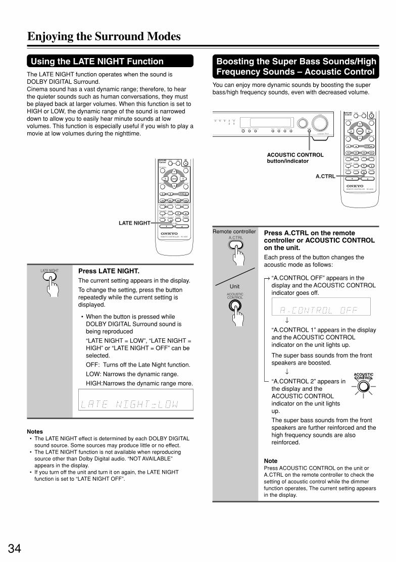
34
SN 29343138 TX-L5.E
Enjoying the Surround Modes
Using the LATE NIGHT FunctionThe LATE NIGHT function operates when the sound isDOLBY DIGITAL Surround.Cinema sound has a vast dynamic range; therefore, to hearthe quieter sounds such as human conversations, they mustbe played back at larger volumes. When this function is set toHIGH or LOW, the dynamic range of the sound is narroweddown to allow you to easily hear minute sounds at lowvolumes. This function is especially useful if you wish to play amovie at low volumes during the nighttime.
Press LATE NIGHT.The current setting appears in the display.
To change the setting, press the buttonrepeatedly while the current setting isdisplayed.
• When the button is pressed whileDOLBY DIGITAL Surround sound isbeing reproduced
“LATE NIGHT = LOW”, “LATE NIGHT =HIGH” or “LATE NIGHT = OFF” can beselected.
OFF: Turns off the Late Night function.
LOW: Narrows the dynamic range.
HIGH:Narrows the dynamic range more.
Notes• The LATE NIGHT effect is determined by each DOLBY DIGITAL
sound source. Some sources may produce little or no effect.• The LATE NIGHT function is not available when reproducing
source other than Dolby Digital audio. “NOT AVAILABLE”appears in the display.
• If you turn off the unit and turn it on again, the LATE NIGHTfunction is set to “LATE NIGHT OFF”.
ACOUSTICCONTROL
DVD MD
MENUTOP MENU
SETUP
SURR MODE
TEST TONE
DISTANCE LATE NIGHT A.CTRL MUTING
VOLUME
CH SEL
STEREO SP SETUP SW MODE
RETURN
REMOTE CONTROLLER RC-453S
PLAY
DVD MDControl
ENTER
LATE NIGHT
DVD MD
MENUTOP MENU
SETUP
SURR MODE
TEST TONE
DISTANCE LATE NIGHT A.CTRL MUTING
VOLUME
CH SEL
STEREO SP SETUP SW MODE
RETURN
REMOTE CONTROLLER RC-453S
PLAY
DVD MDControl
ENTER
A.CTRL
SUBWOOFER MODESURROUND STEREOACOUSTICCONTROLTUNING/PRESET
DVD / C D VIDEO 1 VIDEO 2 HD MD / TAPE
FM AM
INPUT
VOLUME
AV RECEIVER TX-L5
MEMORY FM MODE
ACOUSTIC CONTROLbutton/indicator
LATE NIGHT
A.CTRL
ACOUSTICCONTROL
Remote controller
Unit
Boosting the Super Bass Sounds/HighFrequency Sounds – Acoustic Control
You can enjoy more dynamic sounds by boosting the superbass/high frequency sounds, even with decreased volume.
Press A.CTRL on the remotecontroller or ACOUSTIC CONTROLon the unit.Each press of the button changes theacoustic mode as follows:
→ “A.CONTROL OFF” appears in thedisplay and the ACOUSTIC CONTROLindicator goes off.
↓“A.CONTROL 1” appears in the displayand the ACOUSTIC CONTROLindicator on the unit lights up.
The super bass sounds from the frontspeakers are boosted.
↓“A.CONTROL 2” appears inthe display and theACOUSTIC CONTROLindicator on the unit lightsup.
The super bass sounds from the frontspeakers are further reinforced and thehigh frequency sounds are alsoreinforced.
NotePress ACOUSTIC CONTROL on the unit orA.CTRL on the remote controller to check thesetting of acoustic control while the dimmerfunction operates, The current setting appearsin the display.

35
SN 29343138 TX-L5.E
To record the input source signal youare currently watching or listening to
Recording of video and/or audio signals can be performed onthe components connected to the VIDEO 1 OUT, HD OUT(audio only) and MD/TAPE OUT (audio only) jacks.
Recording a sourceRecording the video from one sourceand the audio from another
You can add the sound from one source to the video ofanother source to make your own video recordings.Below is an example of recording the sound from a MD playerconnected to MD/TAPE L/R jacks and the video from a videocamera connected to VIDEO 2 IN VIDEO jack to videocassette tape in a video cassette recorder connected to theVIDEO 1 OUT L/R and VIDEO jacks.
VIDEOIN IN OUT ININOUT IN
DVD/CDMONOUT
DVD/CD
L
R
IN
AUDIO
VIDEO 1 VIDEO 2 MD/TAPE
OUT INOUT INOUT ININ
HDDVD/CD
L
R
VIDEO 1 VIDEO 2 VVIDEO 1
Videocamera
MD playerVideo cassette
recorder
Insert a MD in the MD player andinsert a tape in the video cameraconnected to the VIDEO 2.
Insert a video tape for recording inthe video cassette recorderconnected to VIDEO 1 OUT.
Press VIDEO 2 on the remotecontroller.
Press MD/TAPE on the remotecontroller.This switches the audio output to MD, butthe video output remains VIDEO 2 that hasbeen selected in step 3.
Start recording on the videocassette recorder and start playingat the MD player and video cameraas desired.The recorded video signal becomes theoutput from the video camera andrecorded audio signal becomes that fromthe MD player.
Notes• You can record analog audio, but not digital audio. Make sure
that you have made a correct analog connection.• If you change the input source during recording, you will record
the audio signals from the newly selected input source and thevideo signals assigned to that input source.
• You cannot record the surround effects.
1
2
1
2
3
4
5
VIDEO 2VIDEO 1DVD/CD
HD MD/TAPEINPUT SELECTOR
VIDEO 2VIDEO 1DVD/CD
HD MD/TAPEINPUT SELECTOR
VIDEO 2VIDEO 1DVD/CD
HD MD/TAPEINPUT SELECTOR
Press an input selector button toselect the input source to record.The input source is now selected and youmay watch or listen to it as desired. Thecurrently selected input source signal tothe VIDEO 1 OUT, HD OUT and MD/TAPEOUT outputs for recording.
Start recording at the recordingcomponent as desired.
Notes:• You can record analog audio, but not digital audio. Make sure
that you have made a correct analog connection.• If you change the input source during recording, you will record
the signals from the newly selected input source.• You cannot record the surround effects.
SUBWOOFER MODESURROUND STEREOACOUSTICCONTROLTUNING/PRESET
DVD / C D VIDEO 1 VIDEO 2 HD MD / TAPE
FM AM
INPUT
VOLUME
AV RECEIVER TX-L5
MEMORY FM MODE
DISPLAYVIDEO 2VIDEO 1DVD/CD
DIMMER
HD TUNERMD/TAPE
DVD MD
STANDBYON
MENUTOP MENU
SETUP
SURR MODE STEREO SP SETUP SW MODE
RETURN
PRESET
PLAY
SLEEP
INPUT SELECTOR
DVD MDControl
ENTER
INPUT dial
INPUTSELECTOR
Remote controller
UnitINPUT

36
SN 29343138 TX-L5.E
Causes
• The power cord (mains lead) isdisconnected.
• The main power is set to OFF.• There is external noise interfering with the
computer circuits of the AV receiver.
• The AC fuse is blown.
• The muting function is activated.• The AV receiver is not properly
connected.• Headphones are connected.
• The speakers are not properly connected.• The listening mode is set to “STEREO” or
“ORCHESTRA.”
• The volume level of the center speaker(“CENTER”) is set to minimum.
• A speaker configuration without the centerspeaker is selected.
• Center speaker is not connected when thespeaker configuration is set 3 ch or 5 ch.
• The TV is not set to receive the outputsignals from the AV receiver.
• The video cable is not connectedsecurely.
• Only the S video connection is made.
• Another input source is selected.
• Power supply fluctuations or otherabnormalities such as static electricitymay interrupt correct operation.
• A wrong DVD•MD control button ispressed.
• No batteries are inserted in the remotecontroller.
• The batteries are worn out.• The remote controller is not pointed at the
remote sensor of the AV receiver.• The remote controller is too far from the
AV receiver.
Remedies
• Check the connection of the power cord(mains lead).
• Turn on the main power.• Switch off the main power, then switch it on
again. If not recovered, disconnect the powercord (mains lead), then connect it again.
• Contact your nearest Onkyo servicecenter.
• Deactivate the muting function.• Check the connections to the AV receiver.
• Decrease the volume, then disconnect theheadphones.
• Check the speaker connections.• No sound is reproduced from the center
speaker when the listening mode is“STEREO” or “ORCHESTRA.”
• Adjust the volume level of the centerspeaker.
• Check that the selected speakerconfiguration includes the center speaker.
• Check the connection between the AVreceiver and the speaker, or set thespeaker configuration to the 2 ch or 4 ch.
• Set the TV to the AV receiver’s input.
• Check the connections between the AVreceiver and TV set.
• Also make video connection.
• Select the appropriate input source.
• Switch off the main power, then switch it onagain. If not recovered, disconnect the powercord (mains lead), then connect it again.
• Press the appropriate DVD•MD controlbutton.
• Insert new batteries.
• Replace with new batteries.• Point the remote controller at the remote
sensor of the AV receiver.• Operate the remote controller within 5 m
(16 feet).
Symptoms
The AV receiver doesn’tswitch on.
No sound is reproduced.
No sound or very littlesound is reproduced fromthe center speaker.
No picture appears on theTV screen.
The sound of the playbacksource is not heard.
The buttons on the remotecontroller and AV receiverdo not operate.
The buttons on the AVreceiver operate but thebuttons on the remotecontroller do not operate.
Check the following guide for the possible cause of a problem before contacting service. Refer also to the respectiveinstruction manuals of the connected components and TV.
Pages
19
1919
–
2912, 13
29
1530
22, 33
20
20
–
12
12-13
26
–
27
7
77
7
Am
plif
ier
TroubleshootingR
emo
te c
on
tro
ller

37
SN 29343138 TX-L5.E
This unit contains a sensitive microcomputer, which under certain circumstances might fail to operate due to excessive noiseinterference. If this happens, press the AV receiver’s SUBWOOFER MODE button and STANDBY/ON button at the sametime until “Clear” appears in the AV receiver’s display. The AV receiver turns into the standby mode, then all the customsettings in the AV receiver’s memory will be erased. Please repeat the custom settings from the beginning.
Symptoms
Too much noise is heard orsound is interruptedoccasionally. (The FMSTEREO indicator does notlight steadily.)
Sound is distorted orsound volume decreases.
Sound is excessivelydistorted.
No preset channels areselected.
Sound is reproduced fromthe speakers but notrecorded.
Causes
• FM stereo waves may produce a hissnoise when a certain level is reached.
• The position or direction of the FMantenna (aerial) is incorrect.
• The station is too weak.
• The radio wave is distorted.• Cars are running or airplanes are flying
near the house.
• There is a tall building or a mountainnearby.[The waves transmitted from thetransmission center (direct waves) andthe waved reflected by buildings ormountains (diffraction waves) interferewith each other causing multi passdistortion.]
• The power cord (mains lead) is unplugged,or the main power is switched off, for along time.
• The sound system you are trying torecord is DTS Surround.
Remedies
• Switch the frequency receiving mode tomono.
• Adjust the position, height, and directionof the FM antenna (aerial).
• Connect an FM outdoor antenna (aerial).Try to use an antenna (aerial) with moreelements.[For installation of the outdoor antenna(aerial), consult your nearest dealer as itrequires special skills and experience.]
––
–
• The preset data in memory is lost. Presetthe radio stations again.
• DTS Surround sound is unable to berecorded.
• Make an analog connection.
Pages
23
16
17
––
–
24
35
35
Tun
erR
eco
rdin
g

38
SN 29343138 TX-L5.E
SpecificationsAMPLIFIER SECTIONPower Output (FTC) All channels 22 watts per channel min.
RMS. into 6 ohms two channel driven,1,000 Hz with no more than 0.6 % totalharmonic distortion.
Continuous power output (DIN)All channels 22 watts per channel min.RMS. into 6 ohms two channel driven,1,000 Hz
Maximun power output (EIAJ)5 × 28 watts at 6 ohms
Dynamic power output 2 × 26 watts at 6 ohms2 × 22 watts at 8 ohms
Total Harmonic Distortion 0.6 % at rated powerIM Distortion 0.6 % at rated powerDamping Factor 40 at 8 ohmsInput Sensitivity and Impedance
DIGITAL INPUT DVD, HD (OPTICAL) 0.5 Vp-p, 75 ohmsDIGITAL INPUT VIDEO 2 (COAXIAL) 0.5 Vp-p, 75 ohmsLINE (DVD/CD, VIDEO 1, 2, HD, TAPE/MD) 150 mV/50 kohmsComposite (DVD/CD, VIDEO 1, 2) 1 Vp-p, 75 ohmsS-VIDEO (DVD/CD, VIDEO 1, 2) Y: 1 Vp-p, 75 ohms
C: 0.28 Vp-p, 75 ohms
TUNER SECTIONTuning Range FM: 87.50 to 108.00 MHz (50 kHz steps)
AM: (USA and Canadian models)530 to 1710 kHz (10 kHz steps)
Usable Sensitivity FM: Mono 11.2 dBf, 1.0 µV (75 ohms IHF)0.9 µV (75 ohms DIN)
Stereo 17.2 dBf, 2.0 µV (75 ohms IHF)23 µV (75 ohms DIN)
AM: 30 µV50 dB Quieting Sensitivity FM: Mono 17.2 dBf, 2.0 µV (75 ohms)
Stereo 37.2 dBf, 20.0 µV (75 ohms)Capture Ratio FM: 2.0 dBImage Rejection Ratio FM: (USA and Canadian models)
40 dBAM: 40 dB
IF Rejection Ratio FM: 90 dBAM: 40 dB
Signal-to-noise Ratio FM: Mono 76 dB, IHFStereo 70 dB, IHF
AM: 40 dBAlternate Channel Att. (+/– 400 kHz) FM: Mono 55 dB, IHFSelectivity FM: 50 dB, DINAM Suppression Ratio FM: 50 dBHarmonic Distortion FM: Mono 0.2 %
Stereo 0.3 %AM: 0.7 %
Frequency response FM: 30 to 15,000 Hz (+/– 1.0 dB)Stereo Separation FM: 45 dB at 1,000 Hz
30 dB at 100 to 10,000 HzStereo Threshold FM: 17.2 dBf, 20 µV (75 ohms)
GENERALPower Supply Rating (USA and Canadian models)and Power Consumption AC 120 V, 60Hz 120W
(Some Asian models)AC 220-230 V, 50/60Hz 105W(Other models)AC 230-240 V, 50Hz 105W
Specifications and features are subject to change without notice.
Output Level and ImpedanceREC OUT (VIDEO 1, TAPE/MD, HD) 150 mV, 2.2 kohmsSUB WOOFER PRE OUT 1 V, 2.2 kohmsComposite (MON OUT, VIDEO 1) 1 Vp-p, 75 ohmsS-VIDEO (MON OUT, VIDEO 1) Y: 1 Vp-p, 75 ohms
C: 0.28 Vp-p, 75 ohmsFrequency Response 10 to 70,000 Hz : +/– 1.5 dBAcoustic Control 1: +6 dB at 40 Hz
2: +10 dB at 40 Hz+7 dB at 10,000 Hz
Signal-to-noise Ratio 100 dB (IHF)Muting –∞ dB
(Other models)522 to 1611 kHz (9 kHz steps)
(Other models)85 dB
Dimensions (W x H x D) 435 × 81 × 377 mm (17-1/8 × 3-3/16 × 14-13/16 ins.)Weight 6.1 kg (13.4 lb.)

39
SN 29343138 TX-L5.E
Memo

W0106-1SN 29343138 E
http://www.onkyo.co.jp/HOMEPAGE
Sales & Product Planning Div. : 2-1, Nisshin-cho, Neyagawa-shi, OSAKA 572-8540, JAPANTel: 072-831-8111 Fax: 072-833-5222 http://www.onkyo-intl.com
ONKYO U.S.A. CORPORATION18 Park Way, Upper Saddle River, N.J. 07458, U.S.A.Tel: 201-785-2600 Fax: 201-785-2650 http://www.onkyousa.com
ONKYO EUROPE ELECTRONICS GmbHLiegnitzerstrasse 6, 82194 Groebenzell, GERMANYTel: +49-8142-4401-0 Fax: +49-8142-4401-555 http://www.onkyo.net
ONKYO CHINA LIMITEDUnits 2102-2107, Metroplaza Tower I, 223 Hing Fong Road, Kwai Chung,N.T., HONG KONG Tel: 852-2429-3118 Fax: 852-2428-9039 http://www.onkyochina.com