Embed Size (px)
Citation preview

®
TXA-600Best.-Nr. 17.1200
TXA-650Best.-Nr. 17.1960
TRANSPORTABLES VERSTÄRKERSYSTEM MIT FUNKEMPFÄNGERPORTABLE AMPLIFIER SYSTEM WITH WIRELESS RECEIVER
BEDIENUNGSANLEITUNG
INSTRUCTION MANUAL
MODE D’EMPLOI
ISTRUZIONI PER L’USO
GEBRUIKSAANWIJZING
MANUAL DE INSTRUCCIONES
INSTRUKCJA OBSLUGI
SIKKERHEDSOPLYSNINGER
SÄKERHETSFÖRESKRIFTER
TURVALLISUUDESTA

2
Bevor Sie einschalten …Wir wünschen Ihnen viel Spaß mit Ihrem neuen Gerätvon MONACOR. Bitte lesen Sie diese Bedienungsanlei-tung vor dem Betrieb gründlich durch. Nur so lernen Siealle Funktionsmöglichkeiten kennen, vermeiden Fehlbe-dienungen und schützen sich und Ihr Gerät vor eventu-ellen Schäden durch unsachgemäßen Gebrauch. HebenSie die Anleitung für ein späteres Nachlesen auf.
Der deutsche Text beginnt auf der Seite 4.
Before switching on …We wish you much pleasure with your new MONACORunit. Please read these operating instructions carefullyprior to operating the unit. Thus, you will get to know allfunctions of the unit, operating errors will be prevented,and yourself and the unit will be protected against anydamage caused by improper use. Please keep the ope-rating instructions for later use.
The English text starts on page 4.
D
A
CH
GB
Avant toute installation …Nous vous souhaitons beaucoup de plaisir à utiliser cetappareil MONACOR. Lisez ce mode d'emploi entière-ment avant toute utilisation. Uniquement ainsi, vous pour-rez apprendre lensemble des possibilités de fonctionne-ment de lappareil, éviter toute manipulation erronée etvous protéger, ainsi que lappareil, de dommages éven-tuels engendrés par une utilisation inadaptée. Conservezla notice pour pouvoir vous y reporter ultérieurement.
La version française se trouve page 8.
Prima di accendere …Vi auguriamo buon divertimento con il vostro nuovo appa-recchio di MONACOR. Leggete attentamente le istruzioniprima di mettere in funzione l'apparecchio. Solo cosìpotete conoscere tutte le funzionalità, evitare comandisbagliati e proteggere voi stessi e l'apparecchio da even-tuali danni in seguito ad un uso improprio. Conservate leistruzioni per poterle consultare anche in futuro.
Il testo italiano inizia a pagina 8.
F
B
CH
I
Antes de la utilización …Le deseamos una buena utilización para su nuevo apa-rato MONACOR. Por favor, lea estas instrucciones deuso atentamente antes de hacer funcionar el aparato.De esta manera conocerá todas las funciones de launidad, se prevendrán errores de operación, usted y elaparato estarán protegidos en contra de todo dañocausado por un uso inadecuado. Por favor, guarde lasinstrucciones para una futura utilización.
El texto en español empieza en la página 12.
E
PL Przed Uruchomieniem …Życzymy zadowolenia z nowego produktu MONACOR.Dzięki tej instrukcji obsługi będą państwo w staniepoznać wszystkie funkcje tego urządzenia. Stosując siędo instrukcji unikną państwo błędów i ewentualnegouszkodzenia urządzenia na skutek nieprawidłowegoużytkowania. Prosimy zachować instrukcję.
Tekst polski zaczyna się na stronie 16.
Før du tænder …God fornøjelse med dit nye MONACOR produkt. Læsvenligst sikkerhedsanvisningen nøje, før du tager pro-duktet i brug. Dette hjælper dig med at beskytte produktetmod ukorrekt ibrugtagning. Gem venligst denne betje-ningsvejledning til senere brug.
Du finder sikkerhedsanvisningen på side 18.
DK
FINInnan du slår på enhetenVi önskar dig mycket glädje med din nya MONACORprodukt. Läs igenom säkerhetsföreskrifterna noga innanenheten tas i bruk. Detta kan förhindra att problem ellerfara för dig eller enheten uppstår vid användning. Sparainstruktionerna för framtida användning.
Säkerhetsföreskrifterna återfinns på sidan 18.
Ennen kytkemistä …Toivomme Sinulle paljon miellyttäviä hetkiä uudenMONACOR laitteen kanssa. Ennen laitteen käyttöäpyydämme Sinua huolellisesti tutustumaan turval-lisuusohjeisiin. Näin vältyt vahingoilta, joita virheellinenlaitteen käyttö saattaa aiheuttaa. Ole hyvä ja säilytä käyt-töohjeet myöhempää tarvetta varten.
Turvallisuusohjeet löytyvät sivulta 18.
S
Voor u inschakelt …Wij wensen u veel plezier met uw nieuwe apparaat vanMONACOR. Lees deze gebruikershandleiding grondigdoor, alvorens het apparaat in gebruik te nemen. Alleenzo leert u alle functies kennen, vermijdt u foutieve bedie-ning en behoedt u zichzelf en het apparaat voor even-tuele schade door ondeskundig gebruik. Bewaar dehandleiding voor latere raadpleging.
De Nederlandstalige tekst vindt u op pagina 12.
NL
B

3
0 10
0 10
-5 +5
-5 +5
-5 +5
-5 +5 0 10 0 10 -5 +5 -5 +5
0 10
VOLUME 1
VOLUME 2
BASS
BASS
TREBLE
TREBLE
VOLUME 4 BASS TREBLE
1JACK-LINEXLR-MIC
2JACK-LINEXLR-MIC 3
4 INT. CD (DECK)
L
L
R
RTXA-6xx
PORTABLE AMPLIFIERSYSTEM
VOLUME 3
MUTE LEVELCH 3+4
PRIORITY MIC 1+2
LIM
AMP ON
1 2 3 4 5 6 7 8 9 10 ➀
– +
POWERLINE LINK
INPUT OUTPUT
EXT. SPEAKER
> 75%
< 25%
- CHARGERED - CHARGEGREEN - STANDBY
TXA-6xx ACTIVE SPEAKER SYSTEM
TRANSFERON AIR
ON
LIM
ONPOWER AMP
B
–
+
1-GROUND2 PHASE
BATTERYON
OFF
Gerät in OFF-Stellung nicht vom Netz getrennt! Unit in OFF position not dis-connected from the mains! In posizione OFF, I’apparecchio non è separatodallarete! En posi t ion OFF (arrêt) , I ’apparei l n ’est pas coupé du secteur!
ACHTUNG! CAUTION! ATTENTION! ATTENZIONE!
Vor Öffnen des Gerätes Netzstecker ziehen, Netzleitungund Netzsicherung nur von Fachpersonal wechseln lassen.Gerät vor Feuchtigkeit und Hitze schützen. ZulässigerEinsatztemperaturbereich 0-40°C. Gerät nur für denangegebenen Zweck verwenden.
Remove the mains plug before opening the unit. Leavereplacing of the mains supply cord and mains fuse toqualified service personnel. Protect the unit against moistureand heat. Permissible operating temperature range 0-40°C.This product is not intended for use other than stated.
Avant d'ouvrir l'appareil, retirez la fiche secteur d'alimentation.Toute intervention sur le câble secteur et le fusible secteurdoit être effectuée uniquement par du personnel qualifié.Protégez l'appareil de l'humidité et de la chaleur. Plageautorisée de la température d'utilisation 0-40°C. A n'utiliserque dans le domaine d'application déterminé.
Staccare la spina di rete prima di aprire l'apparecchio, e farcambiare il cavo di rete ed il fusibile di rete solo da personaesperta. Proteggere l'apparecchio dall'umidità e dal calore.Campo della temperatura d'impiego ammessa 0-40°C.Usare l'apparecchio solo per lo scopo indicato.
ACHTUNG! CAUTION! ATTENTION! ATTENZIONE!
230 V~ /50 Hz/45VA
F 630 mAL
SERIAL-NO. FREQUENCY
863.05 MHz864.80 MHz
15 16 17 18 19 20 21 ➁
11
12
13
14
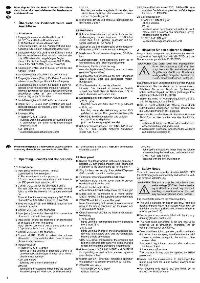
Bitte klappen Sie die Seite 3 heraus. Sie sehendann immer die beschriebenen Bedienelementeund Anschlüsse.
1 Übersicht der Bedienelemente undAnschlüsse
1.1 Frontseite1 Eingangsbuchsen für die Kanäle 1 und 2
(XLR/6,3-mm-Klinken-Kombibuchse):XLR-Anschluss für ein Mikrofon oderKlinkenanschluss für ein Audiogerät mit Line-Ausgang (CD-Spieler, Kassettenrecorder etc.)
2 Lautstärkeregler VOLUME für die Kanäle 1 und 2Bei eingeschaltetem Funkmikrofon leuchtet dierote LED neben dem zugehörigen Regler:Kanal 1 für die Empfangsfrequenz 863,05 MHz,Kanal 2 für 864,80 MHz (nur bei TXA-650)
3 Klangregler BASS und TREBLE jeweils für dieKanäle 1 und 2
4 Lautstärkeregler VOLUME 3 für den Kanal 3
5 Eingangsbuchsen (Cinch) für Kanal 3 zum An-schluss eines Audiogerätes mit Line-Ausgang
6 Eingangsbuchsen (Cinch) für Kanal 4 zum An-schluss eines Audiogerätes mit Line-AusgangHinweis: Entweder an diese Buchsen ein Gerätanschließen oder an den 3,5-mm-Klinken-stecker (11) einen CD-Spieler
7 Lautstärkeregler VOLUME 4 für den Kanal 4
8 Regler MUTE LEVEL zum Einstellen der Laut-stärkeabsenkung der Kanäle 3 und 4 bei Mikro-fondurchsagen
9 Anzeige-LEDsPRIORITY MIC 1+2, grün
leuchtet, wenn die Lautstärke der Kanäle 3 und4 automatisch bei einer Mikrofondurchsageabgesenkt wird
AMP ON, gelbleuchtet bei eingeschaltetem Gerät
LIM, rotleuchtet, wenn der integrierte Limiter die Laut-stärke beim Erreichen des maximalen, unver-zerrten Pegels begrenzt
10 Klangregler BASS und TREBLE gemeinsam fürdie Kanäle 3 und 4
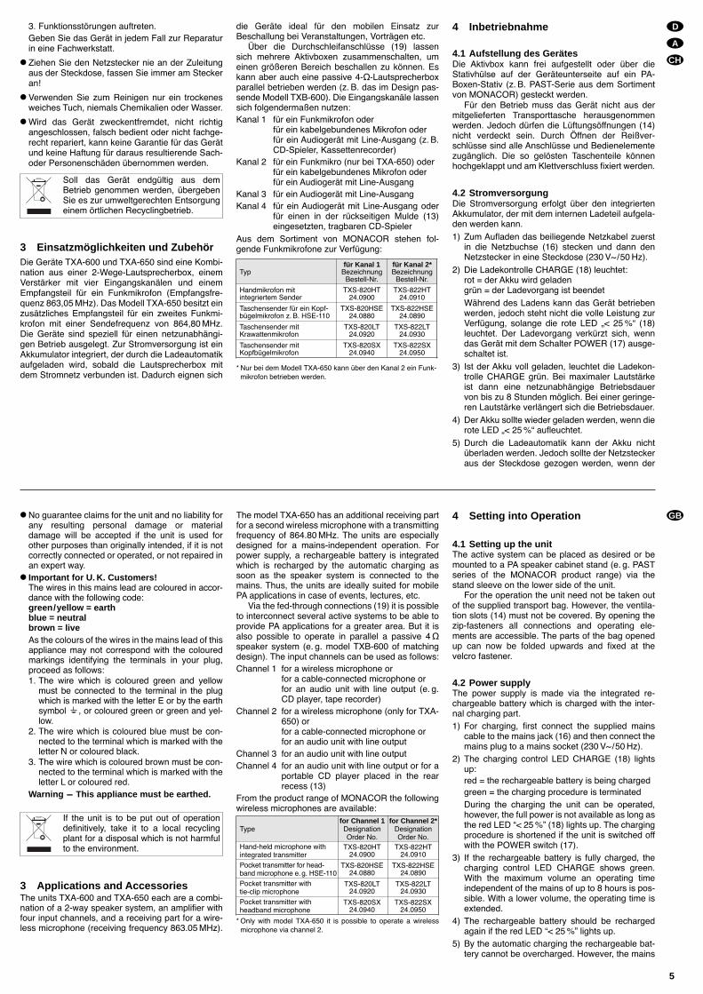
1.2 Rückseite11 3,5-mm-Klinkenstecker zum Anschluss an den
Audioausgang eines tragbaren CD-Spielers(siehe Kap. 4.3.3); parallel geschaltet mit denCinch-Buchsen (6) für Kanal 4
12 Stecker für die Stromversorgung eines tragbarenCD-Spielers (5 V , Innenkontakt = Pluspol)
13 Mulde zum Einsetzen eines tragbaren CD-Spie-lers
14 Lüftungsschlitze; nicht abdecken, damit es imGerät nicht zu einer Überhitzung kommt!
15 Halterung für die Netzsicherung;eine durchgebrannte Sicherung nur durch einegleichen Typs ersetzen
16 Netzbuchse zum Anschluss an eine Steckdose(230 V~/50 Hz) über das beiliegende Verbin-dungskabel
17 Ein-/Ausschalter für das VerstärkerteilHinweis: Das Ladeteil ist immer in Betrieb,sobald das Gerät über die Netzbuchse (16) miteiner Steckdose verbunden wird.
18 Ladeanzeige für den internen Akkumulator> 75 %, grün
leuchtet, wenn der Akku über 75 % geladen ist< 25 %, rot
leuchtet, wenn die Akkuladung unter 25 %gefallen ist und der Akku geladen werden sollte
CHARGE, Betriebsanzeige für das Ladeteilrot: der Akku wird geladengrün: der Ladevorgang ist beendet
19 6,3-mm-Klinkenbuchsen LINE LINK INPUT undOUTPUT zum Betrieb mehrerer Aktivboxen(siehe Kap. 4.3.4)
20 6,3-mm-Klinkenbuchse EXT. SPEAKER zumparallelen Betrieb einer passiven 4-Ω-Lautspre-cherbox, z. B. TXB-600
21 BetriebsanzeigenTRANSFER ON AIR, grün
ohne FunktionLIM, rot
leuchtet, wenn der integrierte Limiter die Laut-stärke beim Erreichen des maximalen, unver-zerrten Pegels begrenzt
POWER AMP ON, gelbleuchtet bei eingeschaltetem Gerät
2 Hinweise für den sicheren GebrauchDieses Gerät entspricht der Richtlinie für elektro-magnetische Verträglichkeit 89/336/EWG und derNiederspannungsrichtlinie 73/23/EWG.
Beachten Sie auch unbedingt die folgenden Punkte: Verwenden Sie das Gerät nur im Innenbereich.
Schützen Sie es vor Tropf- und Spritzwasser,hoher Luftfeuchtigkeit und Hitze (zulässiger Ein-satztemperaturbereich 0 40 °C).
Stellen Sie keine mit Flüssigkeit gefüllten Gefäße,z. B. Trinkgläser, auf das Gerät.
Die im Gerät entstehende Wärme muss durchLuftzirkulation abgegeben werden. Decken Siedie Lüftungsöffnungen (14) nicht ab.
Nehmen Sie das Gerät nicht in Betrieb und ziehenSie sofort den Netzstecker aus der Steckdose,wenn:1. sichtbare Schäden am Gerät oder an der Netz-
anschlussleitung vorhanden sind,2. nach einem Sturz oder Ähnlichem der Verdacht
auf einen Defekt besteht,
WARNUNG Das Gerät wird mit lebensgefähr-licher Netzspannung (230 V~) ver-sorgt. Nehmen Sie deshalb nie selbstEingriffe am Gerät vor. Durch un-sachgemäßes Vorgehen besteht dieGefahr eines elektrischen Schlages.
Please unfold page 3. Then you can always see theoperating elements and connections described.
1 Operating Elements and Connections
1.1 Front panel1 Input jacks for the channels 1 and 2
(combined XLR/6.3 mm jack):XLR connection for a microphone or6.3 mm connection for an audio unit with line out-put (CD player, tape recorder, etc.)
2 Control VOLUME for the channels 1 and 2The red LED next to the corresponding controllights up with the wireless microphone switchedon.Channel 1 for the receiving frequency 863.05 MHz,channel 2 for 864.80 MHz (only for TXA-650)
3 Tone controls BASS and TREBLE, each for thechannels 1 and 2
4 Control VOLUME 3 for channel 35 Input jacks (phono) for channel 3 for connection
of an audio unit with line output6 Input jacks (phono) for channel 4 for connection
of an audio unit with line outputNote: either connect a unit to these jacks or aCD player to the 3.5 mm plug (11)
7 Control VOLUME 4 for channel 48 Control MUTE LEVEL to adjust the volume
attenuation of channels 3 and 4 in case of micro-phone announcements
9 Indicating LEDsPRIORITY MIC 1+2, green
lights up if the volume of channels 3 and 4 isautomatically attenuated in case of a micro-phone announcement
AMP ON, yellowlights up with the unit switched on
LIM, redlights up if the integrated limiter limits the volumewhen reaching the maximum, undistorted level
10 Tone controls BASS and TREBLE in common forchannels 3 and 4
1.2 Rear panel11 3.5 mm plug for connection to the audio output of a
portable CD player (see chapter 4.3.3); connectedin parallel to the phono jacks (6) for channel 4
12 Plug for the power supply of a portable CD player(5 V , inside contact = positive pole)
13 Recess for inserting a portable CD player
14 Ventilation slots; do not cover them to preventoverheating inside the unit!
15 Support for the mains fuse;only replace a blown fuse by one of the same type
16 Mains jack for connection to a mains socket(230 V~/50 Hz) via the supplied connection cable
17 POWER switch for the amplifier partNote: the charging part is always in operation assoon as the unit is connected via the mains jack(16) to a mains socket
18 Charging control LED for the internal rechargea-ble battery> 75 %, green
lights up if the rechargeable battery is chargedmore than 75 %
< 25 %, redlights up if the charge of the rechargeable bat-tery has fallen below 25 % and the rechargablebattery should be charged
CHARGE, power indication for the charging partred: the rechargeable battery is being charged green: the charging procedure is terminated
19 6.3 mm jacks LINE LINK INPUT and OUTPUTfor operating several active speaker systems(see chapter 4.3.4)
20 6.3 mm jack EXT. SPEAKER for parallel operationof a passive 4Ω speaker system, e. g. TXB-600
21 POWER indicationsTRANSFER ON AIR, green
without function
LIM, redlights up if the integrated limiter limits the volumewhen reaching the maximum, undistorted level
POWER AMP ON, yellowlights up with the unit switched on
2 Safety NotesThis unit corresponds to the directive 89/336/EECfor electromagnetic compatibility and to the low volt-age directive 73/23/EEC.
It is essential to observe the following items: The unit is suitable for indoor use only. Protect it
against dripping water and splash water, high airhumidity, and heat (admissible ambient tempera-ture range 0 40 °C).
Do not place any vessels filled with liquid, e. g.drinking glasses, on the unit.
The heat being generated in the unit has to beremoved via air circulation. Therefore, the airvents (14) must not be covered.
Do not set the unit into operation, and immediatelydisconnect the mains plug from the mains socket if1. there is visible damage to the unit or to the
mains cable,2. a defect might have occurred after a drop or
similar accident,3. there are malfunctions.The unit must in any case be repaired by skilledpersonnel.
Never pull the mains cable to disconnect themains plug from the mains socket, always seizethe plug!
For cleaning only use a dry, soft cloth, by nomeans chemicals or water.
WARNING The unit is supplied with hazardousmains voltage (230 V~). Leave servic-ing to skilled personnel only. Inexperthandling or modification of the unitmay cause an electric shock hazard.
4
GB
D
A
CH
3. Funktionsstörungen auftreten.Geben Sie das Gerät in jedem Fall zur Reparaturin eine Fachwerkstatt.
Ziehen Sie den Netzstecker nie an der Zuleitungaus der Steckdose, fassen Sie immer am Steckeran!
Verwenden Sie zum Reinigen nur ein trockenesweiches Tuch, niemals Chemikalien oder Wasser.
Wird das Gerät zweckentfremdet, nicht richtigangeschlossen, falsch bedient oder nicht fachge-recht repariert, kann keine Garantie für das Gerätund keine Haftung für daraus resultierende Sach-oder Personenschäden übernommen werden.
3 Einsatzmöglichkeiten und ZubehörDie Geräte TXA-600 und TXA-650 sind eine Kombi-nation aus einer 2-Wege-Lautsprecherbox, einemVerstärker mit vier Eingangskanälen und einemEmpfangsteil für ein Funkmikrofon (Empfangsfre-quenz 863,05 MHz). Das Modell TXA-650 besitzt einzusätzliches Empfangsteil für ein zweites Funkmi-krofon mit einer Sendefrequenz von 864,80 MHz.Die Geräte sind speziell für einen netzunabhängi-gen Betrieb ausgelegt. Zur Stromversorgung ist einAkkumulator integriert, der durch die Ladeautomatikaufgeladen wird, sobald die Lautsprecherbox mitdem Stromnetz verbunden ist. Dadurch eignen sich
die Geräte ideal für den mobilen Einsatz zurBeschallung bei Veranstaltungen, Vorträgen etc.
Über die Durchschleifanschlüsse (19) lassensich mehrere Aktivboxen zusammenschalten, umeinen größeren Bereich beschallen zu können. Eskann aber auch eine passive 4-Ω-Lautsprecherboxparallel betrieben werden (z. B. das im Design pas-sende Modell TXB-600). Die Eingangskanäle lassensich folgendermaßen nutzen:Kanal 1 für ein Funkmikrofon oder
für ein kabelgebundenes Mikrofon oderfür ein Audiogerät mit Line-Ausgang (z. B.CD-Spieler, Kassettenrecorder)
Kanal 2 für ein Funkmikro (nur bei TXA-650) oderfür ein kabelgebundenes Mikrofon oderfür ein Audiogerät mit Line-Ausgang
Kanal 3 für ein Audiogerät mit Line-AusgangKanal 4 für ein Audiogerät mit Line-Ausgang oder
für einen in der rückseitigen Mulde (13)eingesetzten, tragbaren CD-Spieler
Aus dem Sortiment von MONACOR stehen fol-gende Funkmikrofone zur Verfügung:
* Nur bei dem Modell TXA-650 kann über den Kanal 2 ein Funk-mikrofon betrieben werden.
4 Inbetriebnahme
4.1 Aufstellung des GerätesDie Aktivbox kann frei aufgestellt oder über dieStativhülse auf der Geräteunterseite auf ein PA-Boxen-Stativ (z. B. PAST-Serie aus dem Sortimentvon MONACOR) gesteckt werden.
Für den Betrieb muss das Gerät nicht aus dermitgelieferten Transporttasche herausgenommenwerden. Jedoch dürfen die Lüftungsöffnungen (14)nicht verdeckt sein. Durch Öffnen der Reißver-schlüsse sind alle Anschlüsse und Bedienelementezugänglich. Die so gelösten Taschenteile könnenhochgeklappt und am Klettverschluss fixiert werden.
4.2 StromversorgungDie Stromversorgung erfolgt über den integriertenAkkumulator, der mit dem internen Ladeteil aufgela-den werden kann.1) Zum Aufladen das beiliegende Netzkabel zuerst
in die Netzbuchse (16) stecken und dann denNetzstecker in eine Steckdose (230 V~/50 Hz).
2) Die Ladekontrolle CHARGE (18) leuchtet:rot = der Akku wird geladengrün = der Ladevorgang ist beendetWährend des Ladens kann das Gerät betriebenwerden, jedoch steht nicht die volle Leistung zurVerfügung, solange die rote LED < 25 % (18)leuchtet. Der Ladevorgang verkürzt sich, wenndas Gerät mit dem Schalter POWER (17) ausge-schaltet ist.
3) Ist der Akku voll geladen, leuchtet die Ladekon-trolle CHARGE grün. Bei maximaler Lautstärkeist dann eine netzunabhängige Betriebsdauervon bis zu 8 Stunden möglich. Bei einer geringe-ren Lautstärke verlängert sich die Betriebsdauer.
4) Der Akku sollte wieder geladen werden, wenn dierote LED < 25 % aufleuchtet.
5) Durch die Ladeautomatik kann der Akku nichtüberladen werden. Jedoch sollte der Netzsteckeraus der Steckdose gezogen werden, wenn der
Soll das Gerät endgültig aus demBetrieb genommen werden, übergebenSie es zur umweltgerechten Entsorgungeinem örtlichen Recyclingbetrieb.
No guarantee claims for the unit and no liability forany resulting personal damage or materialdamage will be accepted if the unit is used forother purposes than originally intended, if it is notcorrectly connected or operated, or not repaired inan expert way.
Important for U. K. Customers!The wires in this mains lead are coloured in accor-dance with the following code:green/yellow = earthblue = neutralbrown = liveAs the colours of the wires in the mains lead of thisappliance may not correspond with the colouredmarkings identifying the terminals in your plug,proceed as follows:1. The wire which is coloured green and yellow
must be connected to the terminal in the plugwhich is marked with the letter E or by the earthsymbol , or coloured green or green and yel-low.
2. The wire which is coloured blue must be con-nected to the terminal which is marked with theletter N or coloured black.
3. The wire which is coloured brown must be con-nected to the terminal which is marked with theletter L or coloured red.
Warning - This appliance must be earthed.
3 Applications and AccessoriesThe units TXA-600 and TXA-650 each are a combi-nation of a 2-way speaker system, an amplifier withfour input channels, and a receiving part for a wire-less microphone (receiving frequency 863.05 MHz).
The model TXA-650 has an additional receiving partfor a second wireless microphone with a transmittingfrequency of 864.80 MHz. The units are especiallydesigned for a mains-independent operation. Forpower supply, a rechargeable battery is integratedwhich is recharged by the automatic charging assoon as the speaker system is connected to themains. Thus, the units are ideally suited for mobilePA applications in case of events, lectures, etc.
Via the fed-through connections (19) it is possibleto interconnect several active systems to be able toprovide PA applications for a greater area. But it isalso possible to operate in parallel a passive 4Ωspeaker system (e. g. model TXB-600 of matchingdesign). The input channels can be used as follows:Channel 1 for a wireless microphone or
for a cable-connected microphone orfor an audio unit with line output (e. g.CD player, tape recorder)
Channel 2 for a wireless microphone (only for TXA-650) orfor a cable-connected microphone orfor an audio unit with line output
Channel 3 for an audio unit with line outputChannel 4 for an audio unit with line output or for a
portable CD player placed in the rearrecess (13)
From the product range of MONACOR the followingwireless microphones are available:
* Only with model TXA-650 it is possible to operate a wirelessmicrophone via channel 2.
4 Setting into Operation
4.1 Setting up the unitThe active system can be placed as desired or bemounted to a PA speaker cabinet stand (e. g. PASTseries of the MONACOR product range) via thestand sleeve on the lower side of the unit.
For the operation the unit need not be taken outof the supplied transport bag. However, the ventila-tion slots (14) must not be covered. By opening thezip-fasteners all connections and operating ele-ments are accessible. The parts of the bag openedup can now be folded upwards and fixed at thevelcro fastener.
4.2 Power supplyThe power supply is made via the integrated re-chargeable battery which is charged with the inter-nal charging part.1) For charging, first connect the supplied mains
cable to the mains jack (16) and then connect themains plug to a mains socket (230 V~/50 Hz).
2) The charging control LED CHARGE (18) lightsup:red = the rechargeable battery is being chargedgreen = the charging procedure is terminatedDuring the charging the unit can be operated,however, the full power is not available as long asthe red LED < 25 % (18) lights up. The chargingprocedure is shortened if the unit is switched offwith the POWER switch (17).
3) If the rechargeable battery is fully charged, thecharging control LED CHARGE shows green.With the maximum volume an operating timeindependent of the mains of up to 8 hours is pos-sible. With a lower volume, the operating time isextended.
4) The rechargeable battery should be rechargedagain if the red LED < 25 % lights up.
5) By the automatic charging the rechargeable bat-tery cannot be overcharged. However, the mains
If the unit is to be put out of operationdefinitively, take it to a local recyclingplant for a disposal which is not harmfulto the environment.
5
GB
D
A
CH
Typfür Kanal 1
BezeichnungBestell-Nr.
Handmikrofon mit integriertem Sender
TXS-820HT24.0900
Taschensender für ein Kopf-bügelmikrofon z. B. HSE-110
TXS-820HSE24.0880
Taschensender mitKrawattenmikrofon
TXS-820LT24.0920
Taschensender mitKopfbügelmikrofon
TXS-820SX24.0940
für Kanal 2*Bezeichnung
Bestell-Nr.
TXS-822HT24.0910
TXS-822HSE24.0890
TXS-822LT24.0930
TXS-822SX24.0950
Typefor Channel 1DesignationOrder No.
Hand-held microphone withintegrated transmitter
TXS-820HT24.0900
Pocket transmitter for head-band microphone e. g. HSE-110
TXS-820HSE24.0880
Pocket transmitter withtie-clip microphone
TXS-820LT24.0920
Pocket transmitter withheadband microphone
TXS-820SX24.0940
for Channel 2*DesignationOrder No.
TXS-822HT24.0910
TXS-822HSE24.0890
TXS-822LT24.0930
TXS-822SX24.0950

Akku voll geladen ist (Anzeige CHARGE leuchtetgrün) und das Gerät längere Zeit nicht benötigtwird. Anderenfalls wird auch bei ausgeschalte-tem Gerät stets ein geringer Strom verbraucht.
4.3 Anschlüsse herstellen
4.3.1 MikrofoneEin Funkmikrofon kann über den Kanal 1 und beidem Modell TXA-650 außerdem über den Kanal 2betrieben werden. Der entsprechende Kanal istdamit belegt. Alternativ lässt sich je ein kabelgebun-denes Mikrofon über einen XLR-Stecker an die zu-gehörige Buchse XLR-MIC (1) anschließen.
4.3.2 AudiogeräteBis zu vier Audiogeräte mit Line-Ausgang, z. B. CD-Spieler, Kassettenrecorder, lassen sich an die Aktiv-box anschließen. Vorrangig sollten dafür die Kanäle3 und 4 verwendet werden, weil diese automatischbei einer Mikrofondurchsage in der Lautstärke abge-senkt werden können. Anschluss:Kanal 1 über die 6,3-mm-Klinkenbuchse JACK-
LINE 1 (1), wenn kein Funkmikrofon die-sen Kanal belegt
Kanal 2 über die 6,3-mm-Klinkenbuchse JACK-LINE2 (1) [bei dem Modell TXA-650 nur, wennkein Funkmikrofon diesen Kanal belegt]
Kanal 3 über die Cinch-Buchsen (5)Kanal 4 über die Cinch-Buchsen (6) oder den Klin-
kenstecker (11) für einen tragbaren CD-Spieler (siehe Kap. 4.3.3)
4.3.3 Tragbarer CD-SpielerEin passender, tragbarer CD-Spieler lässt sich in dierückseitige Mulde (13) einsetzen. Zum Befestigenliegen Klettverschlüsse in der Mulde. Benötigt derCD-Spieler eine Betriebsspannung von 5 V, kann erüber den Gleichstromstecker (12) versorgt werden.Am Innenkontakt des Steckers liegt der Pluspol an.Bei Bedarf muss ein Adapter verwendet werden.Den 3,5-mm-Klinkenstecker (11) in den Audioaus-gang des CD-Spielers stecken. Damit belegt derCD-Spieler den Kanal 4.
4.3.4 Mehrere Aktivboxen parallel betreibenWerden mehrere Aktivboxen zur Beschallung be-nötigt, diese über die Buchsen LINE LINK (19) ver-binden:
1) Die Buchse OUTPUT des Hauptgerätes, an demalle Audiogeräte und Mikrofone angeschlossensind, über ein Audiokabel mit 6,3-mm-Klinkenste-ckern an die Buchse INPUT des zweiten Gerätesanschließen.
2) Die Buchse OUTPUT des zweiten Gerätes mitder Buchse INPUT des dritten Gerätes verbindenusw.
3) An den zusätzlichen Geräten stets alle ReglerVOLUME (2, 4, 7) auf 0 stellen, weil die Laut-stärke und der Klang nur über das Hauptgeräteingestellt werden.
4.3.5 Passive LautsprecherboxWird zur Beschallung zusätzlich eine Lautsprecher-box (ohne Verstärker) benötigt, kann diese an dieBuchse EXT. SPEAKER (20) angeschlossen wer-den. Die Impedanz der Lautsprecherbox mussmindestens 4Ω betragen. Die LautsprecherboxTXB-600 ist speziell für diesen Zweck vorgesehen.
4.4 Bedienung
1) Vor dem Einschalten alle Regler VOLUME (2, 4,7) auf 0 drehen, um Einschaltgeräusche zu ver-meiden.
2) Mit dem Schalter POWER (17) das Gerät ein-schalten. Die gelben LEDs AMP ON (9, 21)leuchten. Das Verstärkerteil und das Empfangs-teil sind in Betrieb.
3) Werden Funkmikrofone verwendet, diese ein-schalten. Die rote LED über dem zugehörigenRegler VOLUME (1) leuchtet. Wenn nicht, dieBatterie des Mikrofons überprüfen oder denAbstand zwischen Gerät und Mikrofon verrin-gern. Die Reichweite beträgt ca. 30 m.
4) Alle angeschlossenen Geräte einschalten undderen Signale mit den entsprechenden ReglernVOLUME (2, 4, 7) mischen oder nach Bedarf ein-und ausblenden. Die Regler der nicht benutztenKanäle stets auf 0 stellen.
Die roten LEDs LIM (9, 21) leuchten, wennder integrierte Limiter die Lautstärke beim Errei-chen des maximalen, unverzerrten Pegels be-grenzt. Sollten die LEDs ständig leuchten, dieLautstärke der entsprechenden Kanäle mit denReglern VOLUME verringern.
5) Den Klang für die Kanäle 1 und 2 getrennt mitden Reglern BASS und TREBLE (3) optimal ein-stellen sowie den Klang für die Kanäle 3 und 4gemeinsam mit den Reglern BASS und TREBLE(10).
6) Erfolgt über Kanal 1 oder 2 eine Mikrofondurch-sage, kann dabei die Lautstärke für die Kanäle 3und 4 automatisch reduziert werden. Dazu dieStärke der Reduzierung mit dem Regler MUTELEVEL (8) einstellen. In der Position 0 erfolgtkeine Lautstärkeabsenkung. Wenn das Gerät beieiner Durchsage die Lautstärke der Kanäle 3 und4 verringert, leuchtet die grüne LED PRIORITYMIC 1+2 (9) auf.
7) Nach dem Betrieb das Gerät mit dem SchalterPOWER ausschalten und bei Verwendung vonFunkmikrofonen nicht vergessen, auch dieseauszuschalten, sonst sind bei dem nächstenBetrieb deren Batterien verbraucht.
VORSICHT Stellen Sie die Lautstärke nie sehrhoch ein. Hohe Lautstärken könnenauf Dauer das Gehör schädigen! Dasmenschliche Ohr gewöhnt sich an sieund empfindet sie nach einiger Zeitals nicht mehr so hoch. Darum einehohe Lautstärke nach der Gewöhn-ung nicht weiter erhöhen.
plug should be disconnected if the rechargeablebattery is fully charged (LED CHARGE showsgreen) and the unit is not used for a longer time.Otherwise, even with the unit switched off, therewill always be a low current consumption.
4.3 Making the connections
4.3.1 MicrophonesA wireless microphone can be operated via channel1 and with model TXA-650 also via channel 2. Thecorresponding channel is thus reserved. Alterna-tively, it is possible to connect a cable-connectedmicrophone each via an XLR plug to the corre-sponding jack XLR-MIC (1).
4.3.2 Audio unitsUp to four audio units with line output, e. g. CDplayer, tape recorder, can be connected to the activespeaker system. Channels 3 and 4 should be usedas a priority because their volume can automaticallybe attenuated in case of a microphone announce-ment. Connection:Channel 1 via the 6.3 mm jack JACK-LINE (1) if no
wireless microphone reserves this chan-nel
Channel 2 via the 6.3 mm jack JACK-LINE 2 (1)[only for model TXA-650 if no wirelessmicrophone reserves this channel]
Channel 3 via the phono jacks (5)Channel 4 via the phono jacks (6) or the 3.5 mm
plug (11) for a portable CD player (seechapter 4.3.3)
4.3.3 Portable CD playerIt is possible to place a matching, portable CD playerinto the rear recess (13). For fixing, velcro fastenersare provided in the recess. If the CD player requiresan operating voltage of 5 V, it is possible to supply itvia the DC plug (12). The positive pole is at theinside contact of the plug. If necessary, an adapter
must be used. Connect the 3.5 mm plug (11) to theaudio output of the CD player. Thus, the CD playerreserves channel 4.
4.3.4 Connection of several active speakersystems in parallel
If several active speaker systems are required forPA applications, connect them via the jacks LINELINK (19):
1) Connect jack OUTPUT of the main unit to whichall audio units and microphones are connectedvia an audio cable with 6.3 mm plugs to jackINPUT of the second unit.
2) Connect jack OUTPUT of the second unit to jackINPUT of the third unit etc.
3) Always set to 0 all controls VOLUME (2, 4, 7) ofthe additional units because the volume and thesound are only set via the main unit.
4.3.5 Passive speaker systemIf a speaker system (without amplifier) is additionallyrequired for PA applications, it may be connected tothe jack EXT. SPEAKER (20). The impedance of thespeaker system must at least be 4Ω. The speakersystem TXB-600 has especially been provided forthis purpose.
4.4 Operation
1) Prior to switching on, set all controls VOLUME (2,4, 7) to 0 to prevent switching-on noise.
2) Switch on the unit with the POWER switch (17).The yellow LEDs AMP ON (9, 21) light up. Theamplifier part and the receiving part are in opera-tion.
3) If wireless microphones are used, switch them on.The red LED above the corresponding controlVOLUME (1) lights up. If not, check the battery ofthe microphone or reduce the distance betweenunit and microphone. The range is approx. 30 m.
4) Switch on all connected units and add their sig-nals with the corresponding controls VOLUME(2, 4, 7) or fade them in or out as required.Always set to 0 the controls of the channels notused.
The red LEDs LIM (9, 21) light up if the inte-grated limiter limits the volume when reachingthe maximum, undistorted level. If the LEDsshould light up permanently, reduce the volumeof the corresponding channels with the controlsVOLUME.
5) Adjust an optimum sound for the channels 1 and2 separately with the controls BASS andTREBLE (3) and the sound for the channels 3and 4 in common with the controls BASS andTREBLE (10).
6) If a microphone announcement is made via chan-nel 1 or channel 2, the volume for the channels 3and 4 can automatically be reduced. For this pur-pose adjust the extent of the reduction with thecontrol MUTE LEVEL (8). In position 0 there isno volume attenuation. If the unit reduces thevolume of channels 3 and 4 during an announce-ment, the green LED PRIORITY MIC 1+2 (9)lights up.
7) After the operation switch off the unit with thePOWER switch. When using wireless micropho-nes, remember to switch them off as well, other-wise their batteries will be exhausted the nexttime the microphones are used.
CAUTION Never adjust a very high volume. Per-manent high volumes may damageyour hearing! The human ear getsaccustomed to high volumes which donot seem to be that high any more aftersome time. Therefore, do not furtherincrease a high volume which has oncebeen adjusted after getting used to it.
6
GB
D
A
CH

5 Technische Daten
Verstärkerteil
Ausgangsleistung: . . . . . . 50 WMAX/36 WRMS
Frequenzbereich: . . . . . . . 60 18 500 Hz
EingängeMic 1 + 2: . . . . . . . . . . . 1,5 mV (XLR)Line 1 + 2: . . . . . . . . . . . 150 mV (6,3-mm-Klinke)Line 3 + 4: . . . . . . . . . . . 150 mV (Cinch)Link: . . . . . . . . . . . . . . . 650 mV (6,3-mm-Klinke)
Ausgang Link: . . . . . . . . . 650 mV (6,3-mm-Klinke)
Klangregler4 x Tiefen: . . . . . . . . . . . ±12 dB/40 Hz4 x Höhen: . . . . . . . . . . ±12 dB/12 kHz
Empfangsteil
EmpfangsfrequenzTXA-600: . . . . . . . . . . . 863,05 MHzTXA-650: . . . . . . . . . . . 863,05 und 864,80 MHz
Reichweite: . . . . . . . . . . . ca. 30 m
Allgemeine Daten
StromversorgungEmpfangs-und Verstärkerteil: . . . . über eingebauten AkkuLadeteil: . . . . . . . . . . . . 230 V~/50 Hz/45 VA
Akku-Typ: . . . . . . . . . . . . . wartungsfreier Blei-Gel-Akku, 12 V/7 Ah
Akku-Betriebsdauer: . . . . bis zu 8 Stunden beimaximaler Leistung
Einsatztemperatur: . . . . . 0 40 °C
Abmessungen (B x H x T): 235 x 450 x 280 mm
GewichtTXA-600: . . . . . . . . . . . 9,7 kgTXA-650: . . . . . . . . . . . 12 kg
Änderungen vorbehalten.
5 Specifications
Amplifier part
Output power: . . . . . . . . . 50 WMAX/36 WRMS
Frequency range: . . . . . . 60 18 500 Hz
InputsMic 1 + 2: . . . . . . . . . . . 1.5 mV (XLR)Line 1 + 2: . . . . . . . . . . 150 mV (6.3 mm jack)Line 3 + 4: . . . . . . . . . . 150 mV (phono)Link: . . . . . . . . . . . . . . . 650 mV (6.3 mm jack)
Output Link: . . . . . . . . . . . 650 mV (6.3 mm jack)
Tone controls4x bass: . . . . . . . . . . . . ±12 dB/40 Hz4x treble: . . . . . . . . . . . ±12 dB/12 kHz
Receiving part
Receiving frequency:TXA-600: . . . . . . . . . . . 863.05 MHzTXA-650: . . . . . . . . . . . 863.05 and 864.80 MHz
Range: . . . . . . . . . . . . . . . approx. 30 m
General specifications
Power supplyreceiving part and amplifier part: . . . . via integrated
rechargeable batterycharging part: . . . . . . . . 230 V~/50 Hz/45 VA
Type of rechargeable battery: . . . . . . . . . . . . . . . maintenance-free
rechargeable lead gelbattery, 12 V/7 Ah
Operating time ofrechargeable battery: . . . . up to 8 hours at
maximum power
Ambient temperature: . . . 0 40 °C
Dimensions (W x H x D): . 235 x 450 x 280 mm
WeightTXA-600: . . . . . . . . . . . 9.7 kgTXA-650: . . . . . . . . . . . 12 kg
Subject to technical modification.
7
GB
D
A
CH
Diese Bedienungsanleitung ist urheberrechtlich für MONACOR ® INTERNATIONAL GmbH & Co. KGgeschützt. Eine Reproduktion für eigene kommerzielle Zwecke – auch auszugsweise – ist untersagt.
All rights reserved by MONACOR ® INTERNATIONAL GmbH & Co. KG. No part of this instruction manualmay be reproduced in any form or by any means for any commercial use.

Ouvrez le présent livret page 4 de manière àvisualiser les éléments et branchements.
1 Eléments et branchements
1.1 Face avant1 Prises dentrée pour les canaux 1 et 2
(prise combo XLR/jack 6,35) : branchement XLR pour un micro ou branchement jack 6,35 pour un appareil audioavec sortie Ligne (lecteur CD, magnétophone )
2 Potentiomètres de réglage de VOLUME pour lescanaux 1 et 2.Si le micro sans fil est allumé, la LED rouge àcôté du réglage correspondant brille :canal 1 pour la fréquence de réception863,05 MHz canal 2 pour 864,80 MHz (uniquement sur lemodèle TXA-650)
3 Egaliseur BASS et TREBLE respectivementpour les canaux 1 et 2
4 Potentiomètre de réglage de VOLUME 3 pour lecanal 3
5 Prises dentrée (RCA) pour le canal 3 pour bran-cher un appareil audio à sortie ligne
6 Prises dentrée (RCA) pour le canal 4 pour bran-cher un appareil audio à sortie ligneConseil : reliez soit un appareil à ces prises soitun lecteur CD à la prise jack 3,5 (11)
7 Potentiomètre de réglage de VOLUME 4 pour lecanal 4
8 Potentiomètre de réglage MUTE LEVEL pourrégler la diminution de volume des canaux 3 et 4lors dannonces micro
9 LEDs daffichage :PRIORITY MIC 1+2 : verte
brille si le volume des canaux 3 et 4 est auto-matiquement diminué lors dune annonce micro
AMP ON : jaunebrille lorsque lappareil est allumé
LIM : rougebrille lorsque le limiteur intégré limite le volumelorsque le niveau maximal non distordu estatteint
10 Egaliseur BASS et TREBLE ensemble pour lescanaux 3 et 4
1.2 Face arrière11 Prise jack 3,5 mâle pour brancher à la sortie au-
dio dun lecteur CD portable (voir chap. 4.3.3) ;branchée en parallèle aux prises RCA (6) pour lecanal 4
12 Prise pour lalimentation dun lecteur CD porta-ble (5 V , contact interne = pôle plus)
13 Renfoncement pour placer un lecteur CD portable
14 Ouïes de ventilation : ne pas obturer pour évitertoute surchauffe de lappareil
15 Support fusible de secteur : tout fusible fondudoit impérativement être remplacé par un fusiblede même type
16 Prise secteur pour brancher à une prise secteur230 V~/50 Hz via le cordon livré
17 Interrupteur Marche/Arrêt pour lélément amplifi-cateurConseil : lélément de charge est toujours enfonctionnement dès que lappareil est relié à uneprise secteur via la prise (16).
18 Affichage de charge pour laccumulateur interne :
> 75 %, vertbrille lorsque laccumulateur est chargé au-delà de 75 %
< 25 %, rougebrille lorsque la charge de laccumulateur estsous 25 % et laccumulateur devrait êtrechargé
CHARGE : témoin de fonctionnement pour lélé-ment charge :Rouge : laccumulateur est chargéVert : le processus de charge est terminé
19 Prises jack 6,35 femelles LINE LINK INPUT etOUTPUT pour faire fonctionner plusieurs en-ceintes actives (voir chapitre 4.3.4)
20 Prise jack 6,35 femelle EXT. SPEAKER pour unfonctionnement parallèle dune enceinte passive4Ω, par exemple TXB-600
21 Témoins de fonctionnement
TRANSFER ON AIR, vertsans fonction
LIM, rougebrille lorsque le limiteur intégré limite le volumesi le niveau maximal non distordu est atteint
POWER AMP ON, jaunebrille lorsque lappareil est allumé
2 Conseils d’utilisation et de sécuritéCet appareil répond à la norme européenne 89/336/CEE relative à la compatibilité électromagnétique età la norme européenne 73/23/CEE portant sur lesappareils à basse tension.
Respectez scrupuleusement les points suivants :
Cet appareil nest conçu que pour une utilisationen intérieur. Protégez-le de tout type de projec-tions deau, des éclaboussures, dune humiditéélevée et de la chaleur (plage de température defonctionnement autorisée : 0 40 °C).
En aucun cas, vous ne devez poser dobjet conte-nant du liquide ou un verre sur lappareil.
La chaleur dégagée par lappareil doit être éva-cuée par la circulation dair. En aucun cas, vousne devez couvrir les ouïes de ventilation (14).
AVERTISSEMENT Lappareil est alimenté par unetension dangereuse 230 V~.Ne faites pas de modificationsur lappareil car en cas demauvaise manipulation, vouspourriez subir une déchargeélectrique.
Vi preghiamo di aprire completamente la pagina 3.Così vedrete sempre gli elementi di comando e icollegamenti descritti.
1 Elementi di comando e collegamenti
1.1 Pannello frontale1 Prese dingresso per i canali 1 e 2 (prese combi
XLR/jack 6,3 mm):presa XLR per un microfono oppurepresa jack per un apparecchio audio con uscitaLine (lettore CD, registratore a casette ecc.)
2 Regolatore VOLUME per i canali 1 e 2.Con il radiomicrofono acceso, il LED rosso vicinoal relativo regolatore è acceso:canale 1 per la frequenza di ricezione 863,05 MHzcanale 2 per 864,80 MHz (solo con TXA-650)
3 Regolatori toni BASS ed TREBLE per i canali 1e 2
4 Regolatore VOLUME 3 per il canale 3
5 Prese dingresso (RCA) per il canale 3 per colle-gare un apparecchio audio con uscita Line
6 Prese dingresso (RCA) per il canale 4 per colle-gare un apparecchio audio con uscita LineN. B.: Collegare un apparecchio con questeprese oppure collegare un lettore CD con il jack3,5 mm (11)
7 Regolatore VOLUME 4 per il canale 4
8 Regolatore MUTE LEVEL per impostare labbas-samento del volume dei canali 3 e 4 durante gliavvisi fatti con il microfono
9 Spie a LED PRIORITY MIC 1+2, verde
è acceso quando il volume dei canali 3 e 4 èabbassato automaticamente durante un avvisofatto con il microfono
AMP ON, gialloè acceso quando lapparecchio è acceso
LIM, rossoè acceso quando il limiter integrato limita ilvolume al raggiungimento del livello massimo,non distorto
10 Regolatore toni BASS e TREBLE, comune per icanali 3 e 4
1.2 Pannello posteriore11 Jack 3,5 mm per il collegamento con luscita
audio di un lettore CD portatile (vedi cap. 4.3.3);in parallelo con le prese RCA (6) per il canale 4
12 Presa di alimentazione per un lettore CD porta-tile (5 V , contatto interno = positivo)
13 Incavo per linserimento di un lettore CD portatile
14 Fessure di aerazione; non coprirle per non surri-scaldare lapparecchio!
15 Supporto per il fusibile di rete;sostituire un fusibile difettoso solo con uno dellostesso tipo
16 Presa rete per il collegamento ad una presa(230 V~/50 Hz) con il cavo in dotazione
17 Interruttore on/off per il modulo amplificatoreN. B.: Il caricabatteria entra in funzione non ap-pena la presa di rete (16) viene collegata conuna presa della rete elettrica.
18 Indicazione dello stato della batteria interna rica-ricabile: > 75 %, verde
è acceso se la batteria è carica oltre il 75 %< 25 %, rosso
è acceso se la carica della batteria è inferioreal 25 %; in questo caso, la batteria dovrebbeessere ricaricata
CHARGE, spia di funzionamento del caricatorerosso: la batteria viene caricataverde: la carica è terminata
19 Prese jack 6,3 mm LINE LINK INPUT e OUTPUTper il funzionamento di più casse attive (vedicap. 4.3.4)
20 Presa jack 6,3 mm EXT. SPEAKER per il funzio-namento in parallelo di un diffusore esterno pas-sivo di 4Ω, p. es. TXB-600
21 Spia di funzionamento TRANFER ON AIR, verde
senza funzioneLIM, rosso
è acceso quando il limiter integrato limita ilvolume al raggiungimento del livello massimo,non distorto
POWER AMP ON, gialloè acceso quando lapparecchio è acceso
2 Avvertenze di sicurezzaQuestapparecchio è conforme alle direttive CE89/336/CEE sulla compatibilità elettromagnetica e73/23/CEE per apparecchi a bassa tensione.
Durante luso si devono osservare assolutamente iseguenti punti: Far funzionare lapparecchio solo allinterno di loca-
li. Proteggerlo dallacqua gocciolante e dagli spruz-zi dacqua, da alta umidità dellaria e dal calore(temperatura dimpiego ammessa fra 0 e 40 °C).
Non depositare sullapparecchio dei contenitoririempiti di liquidi, p. es. bicchieri.
Devessere garantita la libera circolazione della-ria per dissipare il calore che viene prodotto allin-terno dellapparecchio. Non coprire in nessunmodo le fessure daerazione (14).
Non mettere in funzione lapparecchio e staccaresubito la spina rete se:1. lapparecchio o il cavo rete presentano dei
danni visibili;
ATTENZIONE Questapparecchio funziona conpericolosa tensione di rete(230 V~). Non intervenire mai alsuo interno; la manipolazione scor-retta può provocare delle scarichepericolose.
8
I
F
B
CH
Ne faites pas fonctionner lappareil ou débran-chez-le immédiatement du secteur lorsque :1. des dommages apparaissent sur lappareil ou
sur le cordon secteur,2. après une chute ou un cas similaire, vous avez
un doute sur létat de lappareil,3. des défaillances apparaissent.Dans tous les cas, les dommages doivent êtreréparés par un technicien spécialisé.
Ne débranchez jamais lappareil en tirant sur lecordon secteur, tenez-le toujours par la prise.
Pour le nettoyer, utilisez uniquement un chiffonsec et doux, en aucun cas, de produits chimiquesou deau.
Nous déclinons toute responsabilité en cas dedommages matériels ou corporels consécutifs silappareil est utilisé dans un but autre que celuipour lequel il a été conçu, sil nest pas correcte-ment branché, utilisé ou nest pas réparé par unepersonne habilitée ; de même, la garantie devien-drait caduque.
3 Possibilités d’utilisation et accessoiresLes appareils TXA-600 et TXA-650 sont la combinai-son dune enceinte 2 voies, dun amplificateur avecquatre canaux dentrée et dun élément récepteurpour un micro sans fil (fréquence de réception863,05 MHz). Le modèle TXA-650 possède un élé-ment récepteur supplémentaire pour un secondmicro sans fil avec une fréquence démission de864,80 MHz. Les appareils sont spécialement con-
çus pour un fonctionnement indépendant du secteur.Pour lalimentation, un accumulateur est intégré, ilest chargé par la charge automatique dès que len-ceinte est reliée à lalimentation. Ainsi, les appareilssont idéalement adaptés à une utilisation mobile pourla sonorisation lors de manifestations, exposés etc.
Via les bornes pour repiquage de signal (19), ilest possible de brancher plusieurs enceintes activesensemble pour pouvoir sonoriser une plus grandezone. Une enceinte passive 4Ω peut égalementfonctionner en parallèle (p. ex. le modèle TXB-600dun design adapté). Les canaux dentrée peuventêtre utilisés comme suit :canal 1 pour un micro sans fil ou
pour un micro relié par câble ou pour un appareil audio avec sortie ligne(par exemple lecteur CD, magnétophone)
canal 2 pour un micro sans fil (uniquement TXA-650) ou un micro relié par câble, ou pour un appareil audio avec sortie ligne
canal 3 pour un appareil audio avec sortie lignecanal 4 pour un appareil audio avec sortie ligne ou
pour un lecteur CD portable placé dans lerenfoncement (13) sur la face arrière.
Dans la gamme MONACOR, les micros sans fil sui-vants peuvent être utilisés :
* Uniquement sur le modèle TXA-650, on peut faire fonctionnerun micro sans fil via le canal 2.
Lorsque lappareil est définitivementretiré du service, vous devez le déposerdans une usine de recyclage adaptéepour contribuer à son élimination nonpolluante.
2. dopo una caduta o dopo eventi simili sussiste ilsospetto di un difetto;
3. lapparecchio non funziona correttamente.Per la riparazione rivolgersi sempre ad unofficinacompetente.
Staccare il cavo rete afferrando la spina, senza ti-rare il cavo.
Per la pulizia usare solo un panno morbido,asciutto; non impiegare in nessun caso prodottichimici o acqua.
Nel caso duso improprio, di collegamenti sba-gliati, dimpiego scorretto o di riparazione scorret-ta cessa la garanzia per lapparecchio e non si as-sume nessuna responsabilità per eventuali danniconsequenziali a persone o a cose.
3 Possibilità d’impiego e accessoriGli apparecchi TXA-600 e TXA-650 sono ognunouna combinazione fra cassa acustica a 2 vie, ampli-ficatore con quattro canali dingresso e modulo rice-vitore per un radiomicrofono (863,05 MHz). Il model-lo TXA-650 è equipaggiato con un modulo ricevitoresupplementare per un secondo radiomicrofono confrequenza di trasmissione di 864,80 MHz. Gli appa-recchi sono previsti in particolar modo per il funzio-namento indipendente dalla rete elettrica. Per lali-mentazione è integrata una batteria ricaricabile cheviene caricata tramite il caricatore automatico nonappena la cassa acustica è collegata con la reteelettrica. In questo modo, gli apparecchi sono adatti
per impieghi mobili, per esempio per sonorizzaremanifestazioni, conferenze ecc.
Grazie ai contatti di attraversamento (19) si pos-sono combinare più casse attive per coprire unazona maggiore da sonorizzare. Ma si può collegarein parallelo anche un diffusore passivo 4Ω (p. es. ilmodello TXB-600 con lo stesso design). I canali din-gresso possono essere utilizzati come segue:canale 1 per un radiomicrofono oppure
per un microfono a cavo oppure per un apparecchio audio con uscita Line(p. es. lettore CD , registratore a cassette)
canale 2 per un radiomicrofono (solo con TXA-650)oppureper un microfono a cavo oppureper un apparecchio audio con uscita Line
canale 3 per un apparecchio audio con uscita Linecanale 4 per un apparecchio audio con uscita Line
oppureper un lettore CD portatile inserito nellin-cavo (13) sul retro
Dal programma di MONACOR sono disponibili iseguenti radiomicrofoni:
* Solo con il modello TXA-650 è possibile utilizzare un radio-microfono sul canale 2.
4 Messa in funzione
4.1 Collocamento dell’apparecchioLa cassa attiva può essere collocata liberamenteoppure può essere montata su un supporto percasse acustiche (p. es. serie PAST del programmaMONACOR) servendosi della bussola per stativosul lato inferiore.
Durante il funzionamento, lapparecchio puòrimanere nella borsa di trasporto. Tuttavia, le fes-sure di aerazione (14) non devono essere coperte.Aprendo gli zip, tutti i collegamenti e elementi dicomando sono accessibili. I lembi della borsa pos-sono essere tirati in alto e fissati con il velcro.
4.2 AlimentazioneLalimentazione avviene tramite la batteria integratache può essere ricaricata con il caricatore interno.1) Per la carica inserire il cavo rete in dotazione
prima nella presa (16) dellapparecchio e quindiin una presa di rete (230 V~/50 Hz).
2) La spia di caricamento CHARGE (18) è accesa:rosso = batteria in caricaverde = carica terminataDurante la carica, lapparecchio può essere usa-to normalmente; tuttavia non è disponibile tutta lasua potenza se è acceso il LED rosso < 25 %(18). La carica è tuttavia più rapida se lappa-recchio è spento con linterruttore POWER (17).
3) Al termine della carica, la spia CHARGE diventaverde. Con il volume al massimo, si può arrivarefino a 8 ore di funzionamento indipendente dallarete elettrica. Riducendo il volume, la durataaumenta.
4) Conviene ricaricare la batteria quando siaccende il LED rosso < 25 %.
5) La carica automatica impedisce la sovraccaricadella batteria. Tuttavia conviene staccare la spinarete se la batteria è carica (la spia CHARGE èverde) e se lapparecchio non viene usato per uncerto periodo. Altrimenti, anche con lappa-recchio spento, si consuma un po di corrente.
Se si desidera eliminare lapparecchiodefinitivamente, consegnarlo per losmaltimento ad unistituzione locale peril riciclaggio.
9
I
F
B
CH
Typepour canal 1Désignation
ref. num.Micro main avec émetteur intégré
TXS-820HT24.0900
Emetteur de poche avec microserre-tête p. ex. HSE-110
TXS-820HSE24.0880
Emetteur de poche avec micro cravate
TXS-820LT24.0920
Emetteur de poche avec micro serre-tête
TXS-820SX24.0940
pour canal 2*Désignation
ref. num.TXS-822HT
24.0910
TXS-822HSE24.0890
TXS-822LT24.0930
TXS-822SX24.0950
Tipoper il canale 1
DesignationOrder No.
Microfono a mano con trasmettitore integrato
TXS-820HT24.0900
Trasmettitore tascabile permicrofono headset p. es. HSE-110
TXS-820HSE24.0880
Trasmettitore tascabile conmicrofono a cravatta
TXS-820LT24.0920
Trasmettitore tascabile conmicrofono headset
TXS-820SX24.0940
per il canale 2*DesignationOrder No.
TXS-822HT24.0910
TXS-822HSE24.0890
TXS-822LT24.0930
TXS-822SX24.0950
4 Fonctionnement
4.1 Positionnement de l’appareilLenceinte active peut être posée librement ouplacée sur un pied denceinte (par exemple sériePAST de la gamme MONACOR) via linsert pourpied situé sur la face inférieure de lappareil.
Pour le fonctionnement, lappareil ne doit pasêtre retiré de la sacoche de transport livrée. Cepen-dant, les ouïes de ventilation (14) ne doivent pasêtre obturées. En ouvrant les fermetures éclair, tousles branchements et les éléments sont accessibles.Les parties de la sacoche ainsi ouvertes peuventêtre relevées et fixées à la fixation velcro.
4.2 AlimentationLalimentation seffectue via laccumulateur intégréqui peut être chargé par lélément de charge interne.1) Pour charger, reliez le cordon secteur livré tout
dabord à la prise secteur (16) de lappareil puisreliez lautre extrémité à une prise secteur230 V~/50 Hz.
2) Le témoin de charge CHARGE (18) brille :rouge = laccumulateur est en chargevert = la charge est terminéePendant la charge, lappareil peut fonctionnermais la puissance nest pas disponible dans satotalité tant que la LED rouge < 25 % (18) brille.Le processus de charge se réduit si lappareil estéteint avec linterrupteur POWER (17).
3) Si laccumulateur est entièrement chargé, le té-moin de charge CHARGE brille en vert. Pour unvolume maximal, une durée de fonctionnementde 8 heures au plus, indépendante du secteur,est possible. Pour un volume plus faible, la duréede fonctionnement augmente.
4) Laccumulateur devrait être à nouveau chargélorsque la LED rouge < 25 % brille.
5) Grâce à la charge automatique, laccumulateurne peut pas être en surcharge ; en revanche, laprise secteur devrait être débranchée si laccu-

mulateur est entièrement chargé (la LEDCHARGE brille en vert) et si lappareil nest pasutilisé pendant une longue période. Sinon, mêmesi lappareil est éteint, un faible courant est tou-jours consommé.
4.3 Elaboration des branchements
4.3.1 MicrophonesUn microphone sans fil peut fonctionner via le canal1 et sur le modèle TXA-650 en plus sur le canal 2.Le canal correspondant est ainsi réservé. A la place,on peut relier un microphone filaire, chacun via unefiche XLR à la prise XLR-MIC (1) correspondante.
4.3.2 Appareils audioOn peut relier à lenceinte active jusquà quatreappareils audio avec sortie ligne, p. ex. lecteur CD,magnétophone. Il est conseillé dutiliser les canaux3 et 4 prioritairement car leur volume peut être auto-matiquement diminué lors dune annonce micro.Branchement :canal 1 via la prise jack 6,35 JACK-LINE 1 (1) si
aucun micro sans fil ne réserve ce canalcanal 2 via la prise jack 6,35 JACK-LINE 2 (1) [sur
le modèle TXA-650 uniquement si aucunmicro sans fil ne réserve ce canal]
canal 3 via les prises RCA (5)canal 4 via les prises RCA (6) ou la prise jack (11)
pour un lecteur CD portable (voir chapitre4.3.3)
4.3.3 Lecteur CD portableUn lecteur CD portable, adapté peut être placé dansle renfoncement sur la face arrière (13). Pour lefixer, des bandes velcro existent dans le renfonce-ment. Si le lecteur CD requiert une tension de fonc-tionnement de 5 V, il peut être alimenté par la prisedalimentation DC (12). Le pôle plus est au contactintérieur de la fiche. Si besoin, un adaptateur doitêtre utilisé. Placez la fiche jack 3,5 (11) dans la sor-
tie audio du lecteur CD. Le lecteur CD réserve ainsile canal 4.
4.3.4 Branchement de plusieurs enceintesactives en parallèle
Si plusieurs enceintes actives sont nécessaires pourune sonorisation, reliez-les via les prises LINE LINK(19) :
1) Reliez la prise OUTPUT de lappareil principalauquel tous les appareils audio et les micros sontreliés, via un cordon audio avec prises jack 6,35,à la prise INPUT du deuxième appareil.
2) Reliez la prise OUTPUT du deuxième appareil àla prise INPUT du troisième appareil etc.
3) Mettez toujours lensemble des potentiomètresVOLUME (2, 4, 7) sur 0 pour les appareils sup-plémentaires car le volume et la tonalité ne serèglent que via lappareil principal.
4.3.5 Enceinte passiveSi pour une sonorisation, une enceinte (sans ampli-ficateur) est en plus nécessaire, elle peut être reliéeà la prise EXT. SPEAKER (20). Limpédance de len-ceinte doit être de 4 ohms au moins ; lenceinte TXB-600 est spécialement prévue pour cette utilisation.
4.4 Fonctionnement
1) Avant la mise sous tension, mettez tous lespotentiomètres VOLUME (2, 4, 7) sur 0 pouréviter tout bruit fort lors de lallumage.
2) Allumez lappareil avec linterrupteur POWER(17). Les LEDs jaunes AMP ON (9, 21) brillent.Lélément amplificateur et lélément récepteursont en fonctionnement.
3) Si des micros sans fil sont utilisés, allumez-les.La LED rouge au-dessus du réglage VOLUME(1) correspondant brille. Si ce nest pas le cas,vérifiez la batterie du micro ou diminuez ladistance entre lappareil et le micro. La portée estde 30 m environ.
4) Allumez lensemble des appareils reliés et mixezleurs signaux avec les potentiomètres VOLUME(2, 4 ,7) correspondants ou si besoin, faites-lesentrer et sortir. Réglez toujours les potentiomè-tres des canaux inutilisés sur 0.
Les LEDs rouges LIM (9, 21) brillent lorsque lelimiteur intégré limite le volume quand le niveaumaximal non distordu est atteint. Si les LEDsdevraient briller en continu, diminuez le volumedes canaux correspondants avec les poten-tiomètres VOLUME.
5) Réglez de manière optimale la tonalité pour lescanaux 1 et 2 séparément avec les potentiomè-tres BASS et TREBLE (3) ainsi que la tonalitépour les canaux 3 et 4 ensemble avec les poten-tiomètres BASS et TREBLE (10).
6) Si une annonce micro est effectuée via le canal 1ou le canal 2, le volume pour les canaux 3 et 4peut automatiquement être diminué. Réglez pource faire la portée de la diminution avec le poten-tiomètre MUTE LEVEL (8). Dans la position 0, ilny a aucune diminution de volume. Si lappareildiminue le volume des canaux 3 et 4 pendantune annonce, la LED verte PRIORITY MIC 1+2(9) brille.
7) Après le fonctionnement, éteignez lappareil aveclinterrupteur POWER et si vous utilisez desmicros sans fil, noubliez pas de les éteindreégalement sinon, lors de la prochaine utilisation,les batteries seront mortes.
ATTENTION Ne réglez pas le volume trop fort. Unvolume trop élevé peut, à longterme, générer des troubles de lau-dition. Loreille humaine shabitue àdes volumes élevés et ne les perçoitplus comme tels au bout dun certaintemps. Nous vous conseillons doncde régler le volume et de ne plus lemodifier.
4.3 Preparare i collegamenti
4.3.1 MicrofoniTramite il canale 1 e, nel modello TXA-650 anchetramite il canale 2, è possibile usare un radiomicro-fono. In questo caso, il relativo canale risulta occu-pato. In alternativa è possibile collegare un micro-fono a cavo con ognuna delle prese XLR-MIC (1)usando un connettore XLR.
4.3.2 Apparecchi audioCon la cassa attiva si possono collegare fino aquattro apparecchi audio con uscita Line, p. es. let-tori CD, registratori a cassette. Per questi si dovreb-bero usare preferibilmente i canali 3 e 4 in quantopossono abbassare il volume automaticamente du-rante gli avvisi fatti con il microfono. Collegamenti:
canale 1 tramite la presa jack 6,3 mm JACK-LINE 1(1), se il canale non è occupato da unradiomicrofono
canale 2 tramite la presa jack 6,3 mm JACK-LINE 2(1) [nel modello TXA-650 solo se il canalenon è occupato da un radiomicrofono]
canale 3 tramite le prese RCA (5)
canale 4 tramite le prese RCA (6) oppure il jack (11)per un lettore CD portatile (vedi cap. 4.3.3)
4.3.3 Lettore CD portatileUn lettore CD portatile adatto può essere inseritonellincavo (13) sul retro. Per il fissaggio, nellincavostesso si trovano dei nastri con velcro. Se il lettoreCD richiede una tensione continua di 5 V può esserealimentato attraverso la spina di corrente continua(12). Il positivo si trova sul contatto interno. Eventu-almente occorre usare un adattatore. Inserire laspina jack 3,5 mm (11) nelluscita audio del lettoreCD. In questo modo, il lettore CD occupa il canale 4.
4.3.4 Collegare più casse attive in paralleloSe per la sonorizzazione sono richieste più casseattive, collegarle tramite le prese LINE LINK (19):
1) Collegare la presa OUTPUT dellapparecchioprincipale, dove sono collegati tutti gli apparecchiaudio e i microfoni, con la presa INPUT del se-condo apparecchio, servendosi di un cavo audiocon connettori jack.
2) Collegare la presa OUTPUT del secondo appa-recchio con la presa INPUT del terzo appa-recchio ecc.
3) Portare tutti i regolatori VOLUME (2, 4, 7) degliapparecchi aggiuntivi sullo 0 perché il volume ei toni vengono regolati solo dallapparecchio prin-cipale.
4.3.5 Diffusore passivoSe per la sonorizzazione è richiesto un diffusore(senza amplificatore), questo può essere collegatocon la presa EXT. SEPAKER (20). Limpedenzadellaltoparlante non deve essere inferiore a 4Ω. Ildiffusore TXB-600 è previsto proprio per questoscopo.
4.4 Funzionamento
1) Prima di accendere, portare tutti i regolatoriVOLUME (2, 4, 7) sullo 0, per escludere rumoridi commutazione.
2) Accendere lapparecchio con linterruttore POW-ER (17). Si accendono i LED gialli AMP ON (9,21). I moduli amplificatore e ricevitore sono infunzione.
3) Se si usano dei radiomicrofono, accenderli. Siaccende la spia rossa sopra il relativo regolatoreVOLUME (1). Altrimenti controllare la batteria delmicrofono o ridurre la distanza fra apparecchio emicrofono. La portata è di 30 metri ca.
4) Accendere tutti gli apparecchi collegati e misce-lare i loro segnali servendosi dei relativi regolatoriVOLUME (2, 4, 7) o inserirli e disinserirli secondonecessità. Portare sullo 0 i regolatori dei canaliliberi.
I LED rossi LIM (9, 21) si accendono quando illimiter integrato limita il volume al raggiungimentodel livello massimo, non distorto. Se i LED doves-sero rimanere accesi occorre ridurre il volume deirelativi canali con i regolatori VOLUME.
5) Regolare in modo ottimale i toni separatamenteper i canali 1 e 2 con laiuto dei regolatori BASS eTREBLE (3), mentre i toni per i canali 3 e 4 ven-gono regolati in comune con i regolatori BASS eTREBLE (10).
6) Se mediante i canali 1 o 2 si deve effettuare unavviso con il microfono, il volume dei canali 3 e 4può essere abbassato automaticamente. Perfare ciò impostare lentità dellabbassamento conil regolatore MUTE LEVEL (8). Nella posizione0 non si ha nessun abbassamento. Se lappa-recchio riduce il volume dei canali 3 e 4 duranteun avviso, il LED verde PRIORITY MIC 1+2 (9) siaccende.
7) Dopo luso spegnere lapparecchio con linterrut-tore POWER e non dimenticare, se si usano deiradiomicrofoni, di spegnere anche questi per nonconsumare le loro batterie.
ATTENZIONE! Mai tenere molto alto il volume. Alungo andare, il volume eccessivopuò procurare danni alludito!Lorecchio si abitua agli alti volumie dopo un certo tempo non se nerende più conto. Non aumentare ilvolume successivamente.
10
I
F
B
CH

5 Caractéristiques techniques
Elément amplificateur
Puissance de sortie : . . . . 50 WMAX/36 WRMS
Bande passante : . . . . . . . 60 18 500 Hz
EntréesMic 1 + 2 : . . . . . . . . . . . 1,5 mV (XLR)Ligne 1 + 2 : . . . . . . . . . 150 mV (jack 6,35)Ligne 3 + 4 : . . . . . . . . . 150 mV (RCA)Link : . . . . . . . . . . . . . . 650 mV (jack 6,35)
Sortie Link : . . . . . . . . . . . 650 mV (jack 6,35)
Egaliseur4 x Graves : . . . . . . . . . ±12 dB/40 Hz4 x Aigus : . . . . . . . . . . ±12 dB/12 kHz
Elément récepteur
Fréquence de réceptionTXA-600 : . . . . . . . . . . 863,05 MHzTXA-650 : . . . . . . . . . . 863,05 MHz et
864,80 MHz
Portée : . . . . . . . . . . . . . . 30 m environ
Généralités
AlimentationEléments récepteur et amplificateur : . . . . . via accumulateur
intégréChargeur : . . . . . . . . . . 230 V~/50 Hz/45 VA
Type daccumulateur : . . . accumulateur recharge-able plomb gel sansentretien, 12 V/7 Ah
Durée de fonctionnement accumulateur : . . . . . . . . . jusquà 8 heures sous
puissance maximale
Température de fonctionnement : . . . . . . . 0 40 °C
Dimensions (L x H x P) : . 235 x 450 x 280 mm
PoidsTXA-600 : . . . . . . . . . . 9,7 kgTXA-650 : . . . . . . . . . . 12 kg
Tout droit de modification réservé.
5 Dati tecnici
Modulo amplificatore
Potenza duscita: . . . . . . . 50 WMAX/36 WRMS
Gamma di frequenze: . . . 60 18 500 Hz
IngressiMic 1 + 2: . . . . . . . . . . . 1,5 mV (XLR)Line 1 + 2: . . . . . . . . . . 150 mV (jack 6,3 mm)Line 3 + 4: . . . . . . . . . . 150 mV (RCA)Link: . . . . . . . . . . . . . . . 650 mV (jack 6,3 mm)
Uscita Link: . . . . . . . . . . . 650 mV (jack 6,3 mm)
Regolatore toni4 x bassi: . . . . . . . . . . . ±12 dB/40 Hz4 x alti: . . . . . . . . . . . . . ±12 dB/12 kHz
Modulo ricevitore
Frequenza di ricezione:TXA-600: . . . . . . . . . . . 863,05 MHzTXA-650: . . . . . . . . . . . 863,05 e 864,80 MHz
Portata: . . . . . . . . . . . . . . ca. 30 m
Dati generali
AlimentazioneModulo ricevitoree amplificatore: . . . . . . tramite batteria ricarica-
bile integrataCaricatore: . . . . . . . . . . 230 V~/50 Hz/45 VA
Tipo batteria ricaricabile: . al gel di piombo, senza manutenzione,12 V/7 Ah
Durata batteria: . . . . . . . . fino a 8 ore a potenzamassima
Temperatura desercizio: . 0 40 °C
Dimensioni (l x h x p): . . . 235 x 450 x 280 mm
PesoTXA-600: . . . . . . . . . . . 9,7 kgTXA-650: . . . . . . . . . . . 12 kg
Con riserva di modifiche tecniche.
11
I
F
B
CH
Notice d’utilisation protégée par le copyright de MONACOR ® INTERNATIONAL GmbH & Co. KG. Toutereproduction même partielle à des fins commerciales est interdite.
La MONACOR ® INTERNATIONAL GmbH & Co. KG si riserva ogni diritto di elaborazione in qualsiasi formadelle presenti istruzioni per l’uso. La riproduzione – anche parziale – per propri scopi commerciali è vietata.

Vouw bladzijde 3 helemaal open, zodat u steedseen overzicht hebt van de bedieningselementenen de aansluitingen.
1 Overzicht van de bedieningselemen-ten en aansluitingen
1.1 Frontpaneel1 Ingangsjacks voor de kanalen 1 en 2
(XLR/ 6,3 mm-combijack):XLR-aansluiting voor een microfoon ofStekkeraansluiting voor een audioapparaat metlijnuitgang (cd-speler, cassetterecorder etc.)
2 Volumeregelaar VOLUME voor de kanalen 1 en2; bij ingeschakelde radiomicrofoon licht de rodeLED naast de bijbehorende regelaar op:kanaal 1 voor de ontvangstfrequentie 863,05 MHz,kanaal 2 voor 864,80 MHz (alleen bij TXA-650)
3 Klankregelaar BASS en TREBLE telkens voorde kanalen 1 en 2
4 Volumeregelaar VOLUME 3 voor het kanaal 3
5 Ingangsjack (Cinch) voor kanaal 3 voor aansluit-ing op een audioapparaat met lijnuitgang
6 Ingangsjack (Cinch) voor kanaal 4 voor aansluit-ing op een audioapparaat met lijnuitgangAanwijzing: Ofwel sluit u op deze jacks eenapparaat aan ofwel op de 3,5 mm-stekker (11)een cd-speler
7 Volumeregelaar VOLUME 4 voor het kanaal 4
8 Regelaar MUTE LEVEL voor het instellen van devolumedemping van de kanalen 3 en 4 bij aan-kondigingen via de microfoon
9 Indicatie-LEDsPRIORITY MIC 1+2, groen
licht op, wanneer het geluidsvolume van dekanalen 3 en 4 automatisch wordt gedempt bijaankondigingen
AMP ON, geellicht op bij ingeschakeld apparaat
LIM, roodlicht op, wanneer de ingebouwde begrenzerhet geluidsvolume bij het bereiken van hetmaximale, onvervormde niveau begrenst
10 Klankregelaar BASS en TREBLE voor de kana-len 3 en 4
1.2 Achterzijde11 3,5-mm-stekker voor de aansluiting van een
draagbare cd-speler op de audio-uitgang (ziehoofdstuk 4.3.3); parallel geschakeld met decinch-jacks (6) voor kanaal 4
12 Stekker voor de voedingsspanning van eendraagbare cd-speler (5 V , inwendige contact =positieve pool)
13 Uitsparing om een draagbare cd-speler in te zet-ten
14 Ventilatieopening; dek deze niet af, zodat hetapparaat niet oververhit raakt!
15 Houder voor de netzekering;vervang een gesmolten zekering uitsluitend dooreen zekering van hetzelfde type
16 POWER-jack voor aansluiting op een stopcon-tact (230 V~/50 Hz) met behulp van de bijgele-verde verbindingskabel
17 POWER-schakelaar voor de versterkermoduleAanwijzing: De laadmodule is steeds in gebruikvan zodra het apparaat via de POWER-jack (16)op een stopcontact wordt aangesloten.
18 Indicatie-LED voor de interne accumulator
> 75 %, groenlicht op, wanneer de accu meer dan 75 % isgeladen
< 25 %, roodlicht op, wanneer de acculading onder 25 % isgezakt en de accu moet worden geladen
CHARGE, POWER-LED voor de laadmodulerood: de accu wordt geladengroen: het laden is beëindigd
19 6,3 mm-stekkerbus LINE LINK INPUT en OUT-PUT voor het gebruik van meerdere actieve luid-sprekerkasten (zie hoofdstuk 4.3.4)
20 6,3 mm-stekkerbus EXT. SPEAKER voor hetparallelle gebruik van een passieve luidspreker-kast van 4Ω, b.v. TXB-600
21 POWER-LEDs
TRANSFER ON AIR, groenzonder functie
LIM, roodlicht op, wanneer de ingebouwde begrenzerhet geluidsvolume bij het bereiken van hetmaximale, onvervormde niveau begrenst
POWER AMP ON, geellicht op bij ingeschakeld apparaat
2 VeiligheidsvoorschriftenDit apparaat is in overeenstemming met de EU-richt-lijn 89/336/EWG voor elektromagnetische com-patibiliteit en 73/23/EWG voor toestellen op laag-spanning.
Let eveneens op het volgende:
Het apparaat is uitsluitend geschikt voor gebruikbinnenshuis. Vermijd druip- en spatwater, uitzon-derlijk warme plaatsen en plaatsen met een hogevochtigheid (toegestaan omgevingstemperatuur-bereik: 0 40 °C).
Plaats geen bekers met vloeistof zoals drinkgla-zen etc. op het apparaat.
De warmte die in het toestel ontstaat, moet doorventilatie worden afgevoerd. Dek de ventilatieope-ningen (14) niet af.
WAARSCHUWING De netspanning (230 V~) vanhet apparaat is levensgevaar-lijk. Open het apparaat niet,want door onzorgvuldige in-grepen loopt u het risico vanelektrische schokken.
Por favor, visualice la página 3. Así podrá ver loselementos operativos y las conexiones según sedescribe.
1 Elementos y conexiones
1.1 Panel frontal1 Jacks de entrada para los canales 1 y 2
(jack XLR/6,3 mm combinado):Conexión XLR para micro o conexión de 6,3 mm para una unidad audio consalida línea (reproductor CD, grabador de cintas,etc.)
2 Control VOLUME para los canales 1 y 2El LED rojo al lado del control correspondientese ilumina con el micro inalámbrico encendido:canal 1 para la frecuencia de recepción863,05 MHz, canal 2 para 864,80 MHz (solamente para TXA-650)
3 Controles de tono BASS y TREBLE, cada unopara los canales 1 y 2
4 Control VOLUME 3 para canal 35 Jacks de entrada (RCA) para el canal 3 para la
conexión de una unidad audio con salida línea6 Jacks de entrada (RCA) para canal 4 para co-
nectar una unidad audio con salida líneaNota: Conecte una unidad a estos jacks o unreproductor CD a la toma de 3,5 mm (11)
7 Control VOLUME 4 para canal 48 Control MUTE LEVEL para ajustar la atenuación
de volumen de los canales 3 y 4 en caso deanuncios de micro
9 Indicadores LEDPRIORITY MIC 1+2, verde
Se ilumina si el volumen de los canales 3 y 4se atenúa automáticamente en caso de anun-cio de micro
AMP ON, amarilloSe ilumina con la unidad encendida
LIM, rojoSe ilumina si el limitador integrado limita elvolumen cuando alcanza el nivel máximo sindistorsionar
10 Controles de tono BASS y TREBLE en comúnpara los canales 3 y 4
1.2 Panel trasero11 Toma de 3,5 mm para conexión a la salida audio
de un reproductor CD portátil (vea cap. 4.3.3);conectado en paralelo a los jacks RCA (6) paracanal 4
12 Toma para la alimentación de un reproductor CDportátil (5 V , en contacto interior = polo positivo)
13 Espacio reservado para insertar un reproductorCD portátil
14 Rejillas de ventilación; no las cubra para preve-nir sobrecalentamiento en la unidad.
15 Soporte para el fusible principal;Solamente cambie un fusible fundido por uno delmismo tipo.
16 Jack principal para conexión a la toma de red(230 V~/50 Hz) mediante el cable suministrado
17 Interruptor POWER para el amplificadorNota: el elemento de carga funciona siempre apartir del momento en que la unidad está conec-tada mediante el jack principal (16) a la toma decorriente
18 Control de carga LED para la batería internarecargable> 75 %, verde
Se ilumina si la batería recargable se cargamás de un 75 %.
< 25 %, rojoSe ilumina si la carga de la batería recargableha bajado más de un 25 % y la batería recar-gable debería cargarse.
CHARGE, indicación de la potencia del car-gador.Rojo: la batería recargable se está cargandoVerde: el procedimiento de carga se ha termi-nado
19 Jacks de 6,3 mm LINE LINK INPUT y OUTPUTpara el funcionamiento de varios recintos activos(vea capítulo 4.3.4)
20 Jack de 6,3 mm EXT. SPEAKER para operaciónen paralelo de un recinto de altavoz pasivo 4Ω,ejemplo: TXB-600
21 Indicaciones POWERTRANSFER ON AIR, verde
Sin funciónLIM, rojo
Se ilumina si el limitador integrado limita elvolumen cuando alcanza el nivel máximo sindistorsionar
POWER AMP ON, amarilloSe ilumina con la unidad encendida
2 Notas de seguridadEsta unidad cumple con la normativa 89/336/EECpara compatibilidad electromagnética y la normativade baja tensión 73/23/EEC.
Es esencial observar los campos siguientes: El aparato está fabricado únicamente para una
utilización en interior. Protéjalo do todo tipo deproyecciones de agua, de salpicaduras, de unahumedad elevada del aire y del calor (tempera-tura de utilización admisible 0 40 °C).
No deposite en ningún caso objetos que conten-gan líquidos, ejemplo: un vaso de agua encimadel aparato.
El calor desprendido dentro del aparato debe sercorrectamente evacuado por una circulación deaire suficiente. Las rejillas de ventilación (14) nodeben ser obstruidas en ningún caso.
PELIGRO La unidad se alimenta por una tensiónpeligrosa (230 V~). Hágala reparar úni-camente por profesionales autorizados.Una manipulación o modificación erró-nea podría causar una descarga eléc-trica.
12
E
NL

Schakel het apparaat niet in en trek onmiddellijkde stekker uit het stopcontact, wanneer:1. het apparaat of het netsnoer zichtbaar bescha-
digd is,2. er een defect zou kunnen optreden nadat een
apparaat bijvoorbeeld gevallen is,3. een apparaat slecht functioneert.Het apparaat moet in elk geval worden herstelddoor een gekwalificeerd vakman.
Trek de stekker nooit met het snoer uit het stop-contact, maar steeds met de stekker zelf!
Verwijder het stof enkel met een droge doek.Gebruik zeker geen chemicaliën of water.
In geval van ongeoorloofd of verkeerd gebruik,verkeerde aansluiting, foutieve bediening of vanherstelling door een niet-gekwalificeerd persoonvervalt de garantie en de verantwoordelijkheidvoor hieruit resulterende materiële of lichamelijkeschade.
3 Toepassingen en toebehorenDe apparaten TXA-600 en TXA-650 zijn een combi-natie van een tweeweg luidsprekerkast, een ver-sterker met vier ingangskanalen en een ontvangst-module voor een radiomicrofoon (ontvangstfrequen-tie 863,05 MHz). Het model TXA-650 is uitgerustmet een bijkomende ontvangstmodule voor eentweede radiomicrofoon met een zendfrequentie van864,80 MHz. De apparaten zijn speciaal voor eennetonafhankelijke werking uitgevoerd. Als voedings-spanning is een accumulator ingebouwd, die door
het automatische laadsysteem wordt opgeladenzodra de luidsprekerkast met netvoeding is verbon-den. Hierdoor zijn de apparaten uitermate geschiktvoor mobiel gebruik zoals het verzorgen van hetgeluid bij voorstellingen, voordrachten etc.
Via de doorvoeraansluitingen (19) kunt u meer-dere actieve luidsprekerkasten aaneenschakelen,om het geluid in een grotere ruimte te kunnen ver-zorgen. U kunt echter ook een passieve luidspreker-kast van 4Ω parallel gebruiken (b.v. het model TXB-600 dat in het design past). De ingangskanalenkunnen als volgt worden gebruikt:kanaal 1 voor een radiomicrofoon of
voor een microfoon met snoer ofvoor een audioapparaat met lijnuitgang(b.v. cd-speler, cassetterecorder)
kanaal 2 voor een radiomicrofoon (alleen bij TXA-650) ofvoor een microfoon met snoer ofvoor een audioapparaat met lijnuitgang
kanaal 3 voor een audioapparaat met lijnuitgangkanaal 4 voor een audioapparaat met lijnuitgang of
voor een draagbare cd-speler die in de uit-sparing (13) achteraan is aangebracht
Uit het gamma van MONACOR zijn volgende radio-microfoons beschikbaar:
* Alleen bij het model TXA-650 kan via kanaal 2 een radiomicro-foon worden gebruikt.
4 Ingebruikneming
4.1 Het apparaat opstellenDe luidsprekerkast kan vrij worden opgesteld, of ukunt hem via de statiefhuls aan de onderzijde ervanop een PA-luidsprekerstatief (b.v. PAST-serie uit hetgamma van MONACOR) monteren.
Voor het gebruik moet het apparaat niet uit de bij-geleverde transporttas worden genomen. De venti-latieopeningen (14) mogen echter niet worden afge-dekt. Door de ritssluitingen te openen, zijn alle aan-sluitingen en bedieningselementen toegankelijk. Dedelen van de tas die u zo losmaakt, kunt u omhoogklappen en met klittenband bevestigen.
4.2 VoedingsspanningDe voedingsspanning gebeurt via de ingebouwdeaccumulator die met de interne laadmodule kanworden geladen.1) Om op te laden, plugt u het bijgeleverde netsnoer
eerst in de POWER-jack (16) en vervolgens denetstekker in een stopcontact (230 V~/50 Hz).
2) De controle-LED CHARGE (18) licht op:rood = de accu wordt geladengroen = het laden is beëindigdTijdens het laden kan het apparaat worden ge-bruikt, maar is niet het volledige vermogen be-schikbaar, zolang de rode < 25 % (18) oplicht.Het opladen wordt verkort, wanneer het apparaatmet de POWER-schakelaar (17) is uitgeschakeld.
3) Als de accu volledig is geladen, licht de controle-LED CHARGE groen op. Bij maximaal geluidsvo-lume is dan een netonafhankelijke bedrijfsduurvan max. 8 uur mogelijk. Bij een kleiner geluids-volume neemt de gebruiksduur toe.
4) De accu moet opnieuw worden geladen, wan-neer de rode LED < 25 % oplicht.
5) Door het automatische laadsysteem kan de accuniet worden overladen. De netstekker van het ap-paraat moet evenwel uit het stopcontact wordengetrokken, wanneer de accu volledig is geladen
Wanneer het apparaat definitief uitbedrijf wordt genomen, bezorg het danvoor milieuvriendelijke verwerking aaneen plaatselijk recyclagebedrijf.
No utilice el aparato y desconéctelo inmediata-mente si:1. Observa daños en el aparato o en el cable de
red.2. Después de una caída o accidente similar, si
tiene duda sobre el estado del aparato.3. Aparecen disfunciones.La unidad tiene que ser reparada en todo casopor un personal especializado.
Nunca desconecte el aparato tirando del cable dered, saque siempre el cable de red sujetándolopor la extremidad.
Para la limpieza, utilice únicamente un trapo secoy suave, en ningún caso productos químicos oagua.
Declinamos toda responsabilidad en caso dedaños corporales o materiales resultantes de lautilización del aparato con otro fin del que le hasido concebido, si no está correctamente conec-tado, utilizado o no ha sido reparado por una per-sona habilitada. Por estos mismos motivoscarecería de todo tipo de garantía.
3 Aplicaciones y accesoriosLa unidades TXA-600 y TXA-650 son una combina-cón de altavoces de 2-vías, un amplificador con cua-tro canales de entrada, y un receptor para un micro in-alámbrico (frecuencia de recepción de 863,05 MHz).El modelo TXA-650 tiene un receptor adicional paraun segundo micro inalámbrico con una frecuencia detransmisión de 864,80 MHz. Las unidades han estadoespecialmente diseñadas para una operación inde-pendiente de la red. Para la alimentación, hay una ba-
tería recargable integrada que se carga automática-mente desde el momento que el altavoz es conectadoa la red. De esta manera, las unidades son idealespara aplicaciones móviles PA en caso de eventos, lec-turas, etc.
Mediante las conexiones a través de la alimenta-ción (19) es posible interconectar diferentes unida-des TXA-600 para permitir a las unidades de proveeraplicaciones PA para una área más importante. Perotambién es posible operar en paralelo un recinto dealtavoz pasivo 4Ω (p. ej.: modelo TXB-600 a juego).Los canales de entrada pueden utilizarse como:
Canal 1 Para micro inalámbrico oPara micro conectado con cable oPara una unidad audio con salida línea(p. ej.: reproductor CD, grabador de cintas)
Canal 2 Para micro inalámbrico (solamente paraTXA-650) oPara micro conectado con cable oPara una unidad audio con salida línea
Canal 3 Para una unidad audio con salida línea
Canal 4 Para una unidad audio con salida línea opara un reproductor CD portátil colocadoen la parte trasera (13).
De la gama MONACOR están disponibles los si-guientes micros:
* Solamente con el modelo TXA-650 es posible hacer funcionarun micro inalámbrico a través del canal 2.
4 Instalación del aparato
4.1 Montaje de la unidadEl recinto activo puede colocarse donde se desee omontarse en un soporte para altavoz PA (ejemplo:serie PAST de MONACOR) vía el vaso para pie dela parte más baja de la unidad.
Para la operación la unidad no debe retirarse dela caja de transporte entregada. No obstante, lasrejillas de (14) no deben obstruirse. Abriendo lascremalleras todos los elementos y conexiones sonaccesibles. Las partes abiertas de la funda puedenplegarse y fijarse con la ayuda del cierre con velcro.
4.2 AlimentaciónLa alimentación se hace vía la batería recargableintegrada que se carga con el cargador interno.1) Para cargar, conecte primeramente el cable su-
ministrado al jack principal (16) y seguidamenteconecte el cable de red a la toma de corriente(230 V~/50 Hz).
2) El control de carga LED CHARGE (18) se ilu-mina:Rojo = la batería recargable está cargándoseVerde = el procedimiento de carga está terminadoDurante la carga, la unidad puede estar en fun-cionamiento, no obstante, la potencia máxima noestá disponible mientras el LED rojo < 25 %(18) está iluminado. El procedimiento de cargaes más rápido si el aparato está apagado con elinterruptor POWER (17).
3) Si la batería recargable está completamente car-gada, el control de carga LED CHARGE está enverde. Con el máximo volumen un tiempo deoperación independiente del principal de más de8 horas es posible. Con un volumen más bajo, eltiempo de operación es ampliado.
4) La batería recargable debería cargarse si el LEDrojo < 25 % se ilumina.
5) Con la carga automática la batería no puede so-brecargarse. De todos modos, el enchufe de red
Cuando la unidad está definitivamenteretirada del servicio, debe depositarla enuna fábrica de reciclaje próxima paracontribuir a su eliminación no contami-nante.
13
E
NL
Tipopara Canal 1Designación
No.Micro de petaca con transmisor integrado
TXS-820HT24.0900
Transmisor de petaca paramicro diadema p. ej. HSE-110
TXS-820HSE24.0880
Transmisor de petaca conmicro con pinza de solapa
TXS-820LT24.0920
Transmisor de petaca conmicro diadema
TXS-820SX24.0940
para Canal 2*Designación
No.TXS-822HT
24.0910
TXS-822HSE24.0890
TXS-822LT24.0930
TXS-822SX24.0950
Typevoor kanaal 1
BenamingBestelnr.
Handmicrofoon met ingebouwde zender
TXS-820HT24.0900
Zakzender voor een hoofdmicrofoon b.v. HSE-110
TXS-820HSE24.0880
Zakzender met dasspeldmicrofoon
TXS-820LT24.0920
Zakzender met hoofdmicrofoon
TXS-820SX24.0940
voor kanaal 2*BenamingBestelnr.
TXS-822HT24.0910
TXS-822HSE24.0890
TXS-822LT24.0930
TXS-822SX24.0950

(LED CHARGE licht groen op) en het apparaatlangere tijd niet wordt gebruikt. Anders is er ookbij uitgeschakeld apparaat steeds een kleinstroomverbruik.
4.3 Het toestel aansluiten
4.3.1 De microfoonsVia kanaal 1 en bij het model TXA-650 ook nog viakanaal 2 kunt u een radiomicrofoon gebruiken. Hetbetreffende kanaal is daarmee bezet. U kunt ook tel-kens een microfoon met snoer via een XLR-stekkeraansluiten op de bijbehorende jack XLR-MIC (1).
4.3.2 AudioapparatuurMaximaal vier audioapparaten met lijnuitgang, b.v.cd-speler, cassetterecorder, kunt u op de actieveluidsprekerkast aansluiten. In de eerste plaats zou uhiervoor de kanalen 3 en 4 moeten gebruiken, omdathet geluidsvolume hiervan bij aankondigingen via demicrofoon kan worden gedempt. Aansluiting:Kanaal 1 via de 6,3 mm-stekkerbus JACK-LINE 1
(1), wanneer geen radiomicrofoon dit ka-naal gebruikt
Kanaal 2 via een 6,3 mm-stekkerbus JACK-LINE 2(1) [bij het model TXA-650 alleen, wanneerdit kanaal niet door een radiomicrofoon ingebruik is]
Kanaal 3 via de cinch-jacks (5)Kanaal 4 via de cinch-jacks (6) of de stekker (11)
voor een draagbare cd-speler (zie hoofd-stuk 4.3.3)
4.3.3 Draagbare cd-spelerU kunt een passende, draagbare cd-speler aan-brengen in de uitsparing (13) aan de achterzijde.Voor de bevestiging zijn velcrosluitingen in de uit-sparing voorzien. Als de cd-speler een bedrijfsspan-ning van 5 V nodig heeft, dan kan hij via de gelijk-stroomstekker (12) worden gevoed. Het inwendigecontact van de stekker is de positieve pool. Indiennodig moet u een adapter gebruiken. Plug de
3,5 mm-stekker (11) in de audio-uitgang van de cd-speler. Hiermee is kanaal 4 bezet door de cd-speler.
4.3.4 Meerdere actieve luidsprekerkasten paral-lel gebruiken
Als voor de PA-toepassing verschillende luidspre-kerkasten nodig zijn, verbindt u deze onderling viade jacks LINE LINK (19):
1) Verbind de jack OUTPUT van de hoofdschakelaar,waarop alle audioapparatuur en microfoons zijnaangesloten, via een audiokabel met de 6,3 mm-jack met de jack INPUT van het tweede toestel.
2) Verbind de jack OUTPUT van het tweede appa-raat met de jacks INPUT van het derde apparaatetc.
3) Stel op de bijkomende apparaten steeds alle re-gelaars VOLUME (2, 4, 7) in op 0, omdat hetgeluidsvolume en de klank alleen via het centraleapparaat worden ingesteld.
4.3.5 Passieve luidsprekerkastIndien voor het verzorgen van het geluid nog eenluidsprekerkast (zonder versterker) nodig is, kunt udeze op de jacks EXT. SPEAKER (20) aansluiten.De impedantie van de luidsprekerkast moet min-stens 4 Ω bedragen. De luidsprekerkast TXB-600 isspeciaal hiervoor bedoeld.
4.4 Bediening
1) Plaats alle regelaars MASTER VOLUME (2, 4, 7)in de nulstand, alvorens het apparaat in te scha-kelen. Zo vermijdt u inschakelploppen.
2) Schakel het apparaat in met de schakelaarPOWER (17). De gele LEDs AMP ON (9, 21)lichten op. De versterkermodule en de ontvangst-module zijn in gebruik.
3) Als u radiomicrofoons gebruikt, schakel deze danin. De rode LED boven de overeenkomstigeregelaar VOLUME (1) licht op. Indien niet, con-troleer dan de batterij van de microfoon of ver-klein de afstand tussen apparaat en microfoon.De reikwijdte bedraagt ca. 30 m.
4) Schakel alle aangesloten apparaten in en menghun signalen met de betreffende regelaars VO-LUME (2, 4, 7), of meng ze naar behoeven in enuit. Plaats de regelaars van de niet gebruiktekanalen steeds in de stand 0.
De rode LEDs lichten op (9, 21), wanneer deingebouwde begrenzer het geluidsvolume bij hetbereiken van het maximale, onvervormde niveaubegrenst. Indien de LEDs continu zouden oplich-ten, verminder dan het geluidsvolume van debetreffende kanalen met de regelaars VOLUME.
5) Stel de klank van de kanalen 1 en 2 afzonderlijkin met de regelaars BASS en TREBLE (3), en stelde klank van de kanalen 3 en 4 samen in met deregelaars BASS en TREBLE (10).
6) Bij aankondigingen via de microfoon op kanaal 1of 2 kan het geluidsvolume voor de kanalen 3 en4 automatisch worden gereduceerd. Stel hier-voor de sterkte van de reductie in met de rege-laar MUTE LEVEL (8). In de stand 0 is er geenvolumedemping. Wanneer het apparaat bij eenaankondiging het geluidsvolume van de kanalen3 en 4 vermindert, licht de groene LED PRIO-RITY MIC 1 + 2 (9) op.
7) Schakel het apparaat na gebruik uit met dePOWER-schakelaar. En denk er bij gebruik vanradiomicrofoons aan ook deze uit te schakelen.Anders zijn de batterijen bij het volgende gebruikleeg.
OPGELET Stel het volume nooit te hoog in. Lang-durige blootstelling aan hoge volumeskan het gehoor beschadigen! Het ge-hoor raakt aangepast aan hoge volu-mes die na een tijdje niet meer zo hooglijken. Verhoog daarom het volume nietnog meer, nadat u er gewoon aan bentgeraakt.
conectado debería desconectarse de la toma decorriente si la batería recargable está completa-mente cargada (mensaje CHARGE en verde) y sila unidad no se utiliza durante un periodo largode tiempo. De otra manera, incluso si la unidadestá desconectada, habrá siempre una baja con-sumición de corriente.
4.3 Conexiones
4.3.1 MicrosUn micro inalámbrico puede funcionar a través delcanal 1 y con el modelo TXA-650 también a travésdel canal 2. El canal correspondiente se reserva deesta manera. Como alternativa, es posible conectarun micro con cable vía toma XLR al jack correspon-diente XLR-MIC (1).
4.3.2 Unidades audioPueden conectarse hasta cuatro unidades consalida línea, p. ej. reproductor CD, grabador de cin-tas. Los canales estéreo 3 y 4 deberían usarse conprioridad porque sus volumen puede atenuarseautomáticamente en caso de anuncio de micro.Conexión:Canal 1 vía el jack 6,3 mm JACK-LINE (1) si no hay
un micro inalámbrico que reserve estécanal
Canal 2 vía el jack 6,3 mm JACK-LINE 2 (1) [sola-mente para el modelo TXA-650 si no haymicro inalámbrico reservando este canal]
Canal 3 vía jacks RCA (5)Canal 4 vía los jacks RCA (6) o la toma de 3,5 mm
(11) para un reproductor CD portátil (veacapítulo 4.3.3)
4.3.3 Reproductor CD portátilEs posible colocar en el sitio reservado (13) de laparte trasera, un reproductor CD portátil. Parafijarlo, dispone de tiras de velcro. Si el reproductorCD requiere un voltaje de funcionamiento de 5 V, esposible suministrarla vía la toma DC (12). El polo
positivo está dentro del contacto interior de la toma.Si es necesario, tiene que utilizarse un adaptador.Conecte la toma de 3,5 mm (11) a la salida audio delreproductor CD. De esta manera, el reproductor CDreserva el canal 4.
4.3.4 Conexión de varios recintos en paraleloSi se requieren varios recintos para aplicacionesPA, conéctelos vía los jacks LINE LINK (19):
1) Conecte el jack OUTPUT de la unidad principal ala que están conectados todos los micros y lasunidades audio vía un cable audio con tomas6,3 mm al jack INPUT de la segunda unidad.
2) Conecte el jack OUTPUT de la segunda unidadal jack INPUT de la tercera unidad etc.
3) Ponga siempre a 0 todos los controles VOLU-ME (2, 4, 7) de las unidades adicionales porqueel volumen y el sonido solamente se fijan vía launidad principal.
4.3.5 Sistema de altavoz pasivoSi un recinto (sin amplificador) se requiere adicio-nalmente para aplicaciones PA, puede conectarseal jack EXT. SPEAKER (20). La impedancia delrecinto del altavoz debe ser al menos de 4Ω. Elrecinto TXB-600 ha estado especialmente fabricadocon este propósito.
4.4 Funcionamiento
1) Antes de encender el aparato, fije todos los con-troles VOLUME (2, 4, 7) a 0 para prevenir ruidoen el encendido.
2) Encienda la unidad con el interruptor POWER(17). Los LEDs amarillos AMP ON (9, 21) seencienden. El amplificador y el receptor están enfuncionamiento.
3) Si se están utilizando micros inalámbricos, en-ciéndalos. El LED rojo encima del control corres-pondiente VOLUME (1) se enciende. Si no lohace, compruebe la batería del micro o reduzcala distancia entre la unidad y el micro. El rangoaprox. es de 30 m.
4) Encienda todas las unidades conectadas yañada sus señales con los controles correspon-dientes VOLUME (2, 4, 7) o hágalas entrar o des-aparecer como requiera. Ponga siempre a 0 loscontroles de los canales que no utiliza.
El LED rojo LIM (9, 21) se enciende si el limi-tador integrado limita el volumen cuando estellega al máximo nivel, sin distorsionar. Si losLEDs deberían iluminarse de manera perma-nente, reduzca el volumen de los canales corres-pondientes con los controles VOLUME.
5) Ajuste un sonido óptimo para los canales 1 y 2por separado con los controles BASS y TREBLE(3) y el sonido para los canales 3 y 4 en comúncon los controles BASS y TREBLE (10).
6) Si un anuncio de micro se hace vía el canal 1 ocanal 2, el volumen de los canales 3 y 4 puedereducirse automáticamente. Para hacerlo, ajustela extensión de la reducción con el control MUTELEVEL (8). En posición 0 no hay atenuación devolumen. Si la unidad reduce el volumen de loscanales 3 y 4 durante un anuncio, el verde LEDPRIORITY MIC 1+2 (9) se enciende.
7) Después de la operación, apague la unidad conel interruptor POWER. Cuando utiliza microsinalámbricos, recuerde de apagarlos también, sino lo hace, podría encontrarse las baterías aca-badas la próxima vez que los utilice.
¡PRECAUCIÓN! Nunca ajuste un volumen muyalto. Los volúmenes elevadospermanentes pueden dañar susoídos. La oreja humana se aco-stumbra a los volúmenes eleva-dos y acaba por no percibirloscuando ha pasado un tiempo. Espor eso que no debe incremen-tar el alto volumen que se ha aju-stado cuando ya esté habituadoa el.
14
E
NL
5 Technische gegevens
Versterkermodule
Uitgangsvermogen: . . . . . 50 WMAX/36 WRMS
Frequentiebereik: . . . . . . . 60 18 500 Hz
IngangenMic 1 + 2: . . . . . . . . . . . 1,5 mV (XLR)Line 1 + 2: . . . . . . . . . . 150 mV (6,3 mm-jack)Line 3 + 4: . . . . . . . . . . 150 mV (Cinch)Link: . . . . . . . . . . . . . . . 650 mV (6,3 mm-jack)
Uitgang Link: . . . . . . . . . . 650 mV (6,3 mm-jack)
Equalizer4 x lage tonen: . . . . . . . ±12 dB/40 Hz4 x hoge tonen: . . . . . . ±12 dB/12 kHz
Ontvangstmodule
OntvangstfrequentieTXA-600: . . . . . . . . . . . 863,05 MHzTXA-650: . . . . . . . . . . . 863,05 en 864,80 MHz
Reikwijdte: . . . . . . . . . . . . ca. 30 m
Algemene gegevens
VoedingsspanningOntvangst-en versterkermodule: . . via ingebouwde accuLaadmodule: . . . . . . . . 230 V~/50 Hz/45 VA
Accutype: . . . . . . . . . . . . . onderhoudsvrijeloodgelaccu, 12 V/7 Ah
Accugebruiksduur: . . . . . . max. 8 uur bij maximaalvermogen
Omgevingstemperatuur: . 0 40 °C
Afmetingen (B x H x D): . . 235 x 450 x 280 mm
GewichtTXA-600: . . . . . . . . . . . 9,7 kgTXA-650: . . . . . . . . . . . 12 kg
Wijzigingen voorbehouden.
5 Especificaciones
Amplificador
Potencia de salida: . . . . . 50 WMAX/36 WRMS
Rango de frecuencia: . . . 60 18 500 Hz
EntradasMic 1 + 2: . . . . . . . . . . . 1,5 mV (XLR)Línea 1 + 2: . . . . . . . . . 150 mV (6,3 mm jack)Línea 3 + 4: . . . . . . . . . 150 mV (RCA)Link: . . . . . . . . . . . . . . . 650 mV (6,3 mm jack)
Salida Link: . . . . . . . . . . . 650 mV (6,3 mm jack)
Controles de tono4x bajo: . . . . . . . . . . . . ±12 dB/40 Hz4x tiple: . . . . . . . . . . . . ±12 dB/12 kHz
Receptor
Frecuencia de recepciónTXA-600: . . . . . . . . . . . 863,05 MHzTXA-650: . . . . . . . . . . . 863,05 y 864,80 MHz
Rango: . . . . . . . . . . . . . . . aprox. 30 m
Especificaciones generalesAlimentación
Receptor yamplificador: . . . . . . . . vía batería recargable
integradaCargador: . . . . . . . . . . . 230 V~/50 Hz/45 VA
Tipo de batería recargable: . . . . . . . . . . . . batería recargable
plomo gel libre de man-tenimiento12 V/7 Ah
Tiempo de funcionamiento de la batería recargable: . hasta 8 horas a poten-
cia máxima
Temperatura ambiente: . . 0 40 °C
Dimensiones (L x A x P): . 235 x 450 x 280 mm
PesoTXA-600: . . . . . . . . . . . 9,7 kgTXA-650: . . . . . . . . . . . 12 kg
Sujeto a modificaciones técnicas.
15
E
NL
Manual de instrucciones protegido por el copyright de MONACOR ® INTERNATIONAL GmbH & Co. KG.Toda reproducción mismo parcial con fines comerciales está prohibida.
Deze gebruiksaanwijzing is auteursrechterlijk beschermd voor MONACOR ® INTERNATIONAL GmbH & Co. KG. Reproductie voor eigen commerciële doeleinden – ook bij wijze van uitzondering – is niet toegestaan.

Prosimy o otworzenie instrukcji na stronie 3,gdzie znajdą Państwo opisywane elementysterujące i gniazda połączeniowe.
1 Elementy i Połączenia
1.1 Panel przedni1 Gniazda wejściowe dla kanału 1 i 2
(gniazdo typu chinch 6,3 mm, XLR):łącze XLR dla mikrofonu lubłącze 6,3 mm dla urządzenia audio z liniowymwyjściem ( odtwarzacz CD, kasetowy, itp.)
2 Regulator głośności VOLUME dla kanałów 1 i 2Czerwona dioda obok odpowiedniego regula-tora świeci się, kiedy podłączony jest mikrofonbezprzewodowy.Kanał 1 dla częstotliwości odbiorczej 863,05 MHz,Kanał 2 dla częstotliwości odbiorczej 864,80 MHz(tylko dla TXA-650)
3 Regulatory barwy dźwięku BASS i TREBLEkażdy dla kanałów 1 i 2
4 Regulator głośności VOLUME 3 dla kanału 35 Gniazda wejściowe stereo (chinch) dla kanału 3
do podłączenia urządzenia audio z wyjściemliniowym
6 Gniazda wejściowe stereo ( chinch) dla kanału4 do podłączenia urządzenia audio z wyjściemliniowymUwaga: podłącz urządzenie do tych gniazdlub odtwarzacz CD do wtyku typu mały jack3,5 mm (11)
7 Regulator głośności VOLUME 4 dla kanału 48 Regulator MUTE LEVEL do ustawiania tłumienia
głośności na kanałach 3 i 4 podczas używaniamikrofonu
9 Wskaźniki:PRIORITY MIC 1+2, zielony
zapala się, jeżeli głośność kanałów 3 i 4 jestautomatycznie tłumiona podczas używaniamikrofonu
AMP ON, żółtyzapala się, kiedy urządzenie jest włączone
LIM, czerwonyzapala się jeżeli zintegrowany limiter ogra-nicza maksymalną głośność przy której niedochodzi jeszcze do zniekształcenia sygnału
10 Regulatory barwy dźwięku BASS i TREBLEwspólne dla kanałów 3 i 4
1.2 Panel tylni11 Wtyk typu mały jack 3,5 mm do podłączenia
wyjścia audio przenośnego odtwarzacza (patrzrozdz. 4.3.3); podłączany równolegle do gniazdphono (6) dla kanału 4
12 Wtyk zasilania przenośnego odtwarzacza CD(5 V , plus znajduje się w środku)
13 Wnęka na przenośny odtwarzacz CD14 Otwory wentylacyjne, nie należy zasłaniać, w
przeciwnym wypadku może dojść do przegrza-nia urządzenia!
15 Obudowa głównego bezpiecznika;Należy wymieniać tylko na bezpiecznik tegosamego typu
16 Gniazdo kabla zasilania łączącego z siecią(230 V~/50 Hz)
17 Włącznik zasilania POWER dla wzmacniaczaUwaga: ładowarka zawsze działa, jeżeli urząd-zenie jest podłączone do sieci zasilającej przezgniazdo (16).
18 Wskaźnik ładowania dla wewnętrznych akumu-latorów> 75 %, zielony
zapala się, jeżeli akumulator jest naładowanyw ponad 75 %
< 25 %, czerwonyzapala się, jeżeli stopień naładowania akumu-latora spadł poniżej 25 %; akumulator powi-nien zostać ponownie naładowany
CHARGE wskaźnik zasilania dla ładowarkiczerwony: akumulator jest ładowanyzielona: ładowanie jest zakończone
19 Gniazdo typu duży jack 6,3 mm LINE LINKINPUT i OUTPUT do obsługi kilku aktywnychsystemów głośnikowych (patrz rozdz. 4.3.4)
20 Gniazdo typu duży jack 6,3 mm EXT. SPEAKERdla równoległej pracy pasywnego systemugłośnikowego o impedancji 4Ω np. TXB-600
21 Wskaźnik zasilania
TRANSFER ON AIR, zielonybez funkcji
LIM, czerwonyzapala się, jeżeli zintegrowany limiter ochra-nia głośniki przed szczytowymi wartościamidźwięku
POWER AMP ON, żółtyzapala się, kiedy urządzenie jest włączone
2 Informacje dotyczące bezpieczeństwaTo urządzenie podlega wytycznym i normom dlaurządzeń zgodnych z 89/336/EEC i spełnia wyma-gania dla urządzeń niskonapięciowych 73/23/EEC.
Proszę zawsze przestrzegać:
Urządzenie jest przeznaczone tylko do użytkuwewnątrz pomieszczeń. Chroń przed wodą, wy-soką wilgotnością i wysoką temperaturą (dopu-szczalny zakres temperatury to 0 – 40 °C).
Na urządzeniu nie stawiać naczyń z płynami np.szklanek z wodą.
Urządzenie generuje ciepło, które neutralizo-wane jest przez cyrkulację powietrza. Z tegowzględu, wloty powietrza (14) nie mogą być blo-kowane.
UWAGA Urządzenie działa na prąd zmienny(230 V~). Naprawy mogą być dokony-wane tylko przez wyszkolony personel.Próby naprawy urządzenia przez oso-by nieupoważnione mogą zakończyćsię porażeniem prądem.
Nie uruchamiać i natychmiast wyłączyć głównąwtyczkę zasilania z prądu:1. jeśli istnieje widoczne uszkodzenie urządzenia
lub kabla zasilającego,2. jeśli uszkodzenie mogło powstać na skutek
upuszczenia urządzenia lub podobnegowypadku,
3. jeśli urządzenie nie działa prawidłowo.Naprawy mogą być dokonywane tylko przezwyszkolony personel.
Nigdy nie ciągnij za kabel zasilający podczasodłączania wtyczki z gniazdka, chwytaj zawszeza wtyczkę.
Do czyszczenia obudowy używać suchej, mięk-kiej ściereczki. Nie stosować wody ani środkówczyszczących.
Producent ani dostawca nie ponosi odpowiedzi-alności za wynikłe szkody materialne, jeśli urząd-zenie było używane niezgodnie z przeznacze-niem, zostało zainstalowane lub obsługiwaneniepoprawnie lub poddawane nieautoryzowan-ym naprawom.
3 Zastosowanie i wyposażenieTXA-600 i TXA-650 są kombinacją dwudrożnegosystemu głośnikowego, wzmacniacza stereo zczterema kanałami wejściowymi i odbiornika dlamikrofonu bezprzewodowego (częstotliwość trans-misji 863,05 MHz). Model TXA-650 ma dodatkowyodbiornik dla drugiego mikrofonu bezprzewodo-wego o częstotliwości transmisji 864,80 MHz. Urzą-dzenia są przeznaczone do pracy nie wymagającej
podłączania do sieci zasilającej. Do zasilania służyzałączony akumulator, który mogą być automatycz-nie ładowany, gdy tylko urządzenie jest podłączonedo sieci zasilającej. Dzięki takiemu rozwiązaniu,urządzenie jest idealne do stosowania w przenoś-nych systemach nagłośnieniowych podczas im-prez, wykładów, itp.
Dzięki łączom przelotowym (19) istnieje moż-liwość podłączenia kilku zestawów TXA-600/TXA-650, co pozwala na działanie na większym obszarze.Można również podłączyć równolegle pasywny sys-tem głośnikowy o impedancji 4Ω (na przykład modelTXB-600 w podobnej stylistyce). Kanały wejściowemogą być wykorzystane w następujący sposób:Kanał 1 dla mikrofonu bezprzewodowego lub
mikrofonu lub urządzenia z wyjściem liniowym (np. odt-warzaczem CD, odtwarzaczem kaseto-wym)
Kanał 2 dla mikrofonu bezprzewodowego (tylkodla modelu TXA-650) lub mikrofonu luburządzenia z wyjściem liniowym
Kanał 3 dla urządzenia z wyjściem liniowymKanał 4 dla urządzenia audio z liniowym wyjściem
lub dla przenośnego odtwarzacza CDZaleca się stosowanie następujących mikrofonówbezprzewodowych z oferty MONACOR:
* Tylko w modelu TXA-650 istnieje możliwość obsługi mikrofonubezprzewodowego przez kanał 2
4 Przygotowanie do pracy
4.1 UstawieniaUrządzenie może być umieszczone według uzna-nia lub zamontowane w stojaku systemu nagłoś-nieniowego (np. seria PAST z oferty MONACOR)dzięki uchwytom znajdującym się w dolnej częściurządzenia.
Urządzenie może pracować bez wyjmowania zfuterału transportowego. Jednak, należy dopilno-wać, aby wyloty wentylacyjne (14) nie były zasło-nięte. Po rozpięciu zamków błyskawicznych, dos-tępne są wszystkie gniazda i regulatory. Otwarteklapy futerału można zwinąć i przymocować u góry.
4.2 ZasilanieDo zasilania służy załączony akumulator, który jestautomatycznie ładowany, gdy tylko urządzenie jestpodłączone do sieci zasilającej.1) Podłącz kabel zasilania (16) do gniazda siecio-
wego (230 V/50 Hz).2) Zaświeci się LED CHARGE (18):
na czerwono = akumulator jest ładowanyna zielono= ładowanie jest zakończonePodczas ładowania urządzenie może normalniefunkcjonować, jednak pełna moc jest dostępnatylko, gdy czerwona dioda LED “< 25 %” (18)zgaśnie. Ładowanie jest skrócone, jeżeli urząd-zenie zostanie wyłączony z prądu za pomocąwłącznika POWER (17).
3) Jeżeli akumulator jest w pełni naładowany,wskaźnik LED CHARGE zaświeci się na zielono.Urządzenie zasilane akumulatorem może pra-cować do ośmiu godzin przy maksymalnejgłośności. Przy mniejszej głośności czas tenjest dłuższy.
4) Akumulator powinien być ponownie naładowany,jeżeli zaświeci się czerwona dioda LED “< 25 %”.
5) Podczas automatycznego ładowania akumula-tor nie zostanie przeładowany. Powinno się jed-nak odłączać urządzenie z sieci zasilającej, jeżeli
Jeśli urządzenie nie będzie już nigdywięcej używane, wskazane jest przeka-zanie go do miejsca utylizacji odpadów,aby zostało utylizowane bez szkody dlaśrodowiska.
16
PL
Typdla kanału 1Oznaczenie
Numer Mikrofon ręczny ze zintegrowanym nadajnikiem
TXS-820HT24.0900
Nadajnik kieszeniowy dla mikrofonu nagłownego HSE-110
TXS-820HSE24.0880
Nadajnik kieszeniowy dlamikrofonu krawatowego
TXS-820LT24.0920
Nadajnik kieszeniowy dlamikrofonu nagłownego
TXS-820SX24.0940
dla kanału 2*Oznaczenie
NumerTXS-822HT
24.0910
TXS-822HSE24.0890
TXS-822LT24.0930
TXS-822SX24.0950

akumulator jest w pełni naładowany (wskaźnikCHARGE świeci się na zielono), a urządzenie niebędzie używane przez dłuższy czas. W przeci-wnym wypadku, nawet przy wyłączonym urząd-zeniu, będzie pobierana niewielka ilość prądu.
4.3 Połączenia
4.3.1 MikrofonyMikrofon bezprzewodowy może być obsługiwanyprzez kanał 1, a przy modelu TXA-650 równieżprzez kanał 2. Odpowiedni kanał zostanie zarezer-wowany tylko dla mikrofonu. Można również po-dłączyć zwykły mikrofon przewodowy do gniazdaXLR-MIC (1).
4.3.2 Urządzenia audioDo systemu głośnikowego można podłączyć doczterech urządzeń audio z wyjściem liniowym np.odtwarzacz CD, odtwarzacz kasetowy. Kanał 3 i 4powinny być używane jako kanały podstawowe,ponieważ głośność na tym kanale jest automatycz-nie zmniejszana, jeżeli używany jest mikrofon.Połączenia:Kanał 1 przez gniazdo typu duży jack 6,3 mm
JACK-LINE 1 (1), jeżeli kanał nie jestzarezerwowany przez mikrofon bezprze-wodowy
Kanał 2 przez gniazdo typu duży jack 6,3 mmJACK-LINE 2 (1), [tylko dla modelu TXA-650, jeżeli kanał nie jest zarezerwowanyprzez mikrofon bezprzewodowy]
Kanał 3 przez gniazda chinch (5)Kanał 4 przez gniazda chinch (6) lub wtyk typu
mały jack 3,5 mm (11) dla przenośnegoodtwarzacza CD (patrz rozdz. 4.3.3)
4.3.3 Przenośny odtwarzacz CDIstnieje możliwość przymocowania przenośnegoodtwarzacza CD we wnęce (13). Do przymocowa-nia odtwarzacza służą rzepy znajdujące się wewnęce. Jeśli odtwarzacz wymaga napięcia robo-
czego 5 V, można podłączyć go do wtyku (12).Bie-gun dodatni znajduje się na wewnętrznym stykuwtyczki. Jeżeli zajdzie taka potrzeba, należy zasto-sować przejściówkę. Podłącz wtyk (11) do wyjściaaudio odtwarzacza. Kanał 4 zostaje zarezerwo-wany dla odtwarzacza.
4.3.4 Podłączanie równoległe kilku aktywnychsystemów głośnikowych
Jeżeli zajdzie taka potrzeba, można podłączyćkilka systemów głośnikowych, służą do tego gnia-zda LINE LINK (19):
1) Podłącz gniazdo OUTPUT głównego urządze-nia, do którego podłączone są wszystkiepozostałe urządzenia audio i mikrofony z gnia-zdem INPUT drugiego urządzenia.
2) Podłącz gniazdo OUTPUT drugiego urządzeniaz gniazdem INPUT kolejnego urządzenia, itd.
3) Należy zawsze ustawiać regulatory głośnościVOLUME (2, 4, 7) dodatkowych urządzeń nazero, ponieważ głośność jest ustawiana tylko naurządzeniu głównym.
4.3.5 Pasywny system głośnikowyJeżeli wymagany jest dodatkowy system głośnikowy(bez wzmacniacza) można go podłączyć go dogniazda EXT. SPEAKER (20). Impedancja głośnikamusi wynosić co najmniej 4Ω. System głośnikowyTXB-600 jest specjalnie przeznaczony do tego celu.
4.4 Obsługa
1) Przed włączeniem ustaw regulatory głośności(2, 4, 7) na zero, w ten sposób unikniesz trzas-ków podczas włączania.
2) Włącz urządzenie włącznikiem POWER (17).Zapalą się żółte diody AMP ON (9, 21). Wzmac-niacz i odbiornik są gotowe do pracy.
3) Jeżeli jest używany, włącz mikrofon bezprzewo-dowy. Zapali się czerwona dioda nad odpowied-nim regulatorem VOLUME (1). Jeżeli nie, należysprawdzić baterie w mikrofonie lub zmniejszyćdystans między urządzeniem i mikrofonem.Zasięg wynosi około 30 m.
4) Włącz podłączone urządzenia i wyreguluj ichsygnały za pomocą regulatorów VOLUME (2, 4,7). Regulatory kanałów nieużywanych powinnybyć zawsze ustawione na “0”.
Zapalą się czerwone diody LIM (9, 21) jeżelizintegrowany limiter ochrania głośniki przedszczytowymi wartościami dźwięku Jeżeli diodyświecą się przez cały czas, należy zmniejszyćgłośność odpowiednich kanałów za pomocąregulatorów VOLUME.
5) Ustaw odpowiednią barwę dźwięku oddzielniedla kanału 1 i 2 za pomocą regulatorów BASS iTREBLE (3), i wspólnie dla kanałów 3 i 4 zapomocą regulatorów BASS i TREBLE (10).
6) Jeżeli na kanale 1 lub 2 jest używany mikrofon,głośność na kanałach 3 i 4 może być automaty-cznie redukowana. W tym celu ustaw zakresredukcji za pomocą regulatora MUTE LEVEL (8).W pozycji zerowej wyciszanie nie działa. Jeżelina kanałach 3 i 4 jest redukowana głośność,zapala się zielony wskaźnik LED PRIORITY MIC1+2 (9).
7) Po zakończeniu pracy należy wyłączyć urządze-nie za pomocą przycisku POWER. Używającmikrofonów bezprzewodowych należy pamiętaćżeby je również wyłączać, w przeciwnymwypadku baterie zostaną wyczerpane i mikro-fony nie będą działały.
UWAGA Nigdy nie ustawiać urządzenia na mak-symalną głośność. Zbyt duże natężeniedźwięku może uszkodzić słuch! Ucholudzkie dostosowuje się do hałasu,który po pewnym czasie nie wydaje sięuciążliwy. Nie wolno zwiększać głośno-ści po przyzwyczajeniu się do poprzed-niego ustawienia.
5 Dane techniczne
WzmacniaczMoc wyjściowa: . . . . . . . . 50 WMAX/36 WRMS
Pasmo przenoszenia: . . . 60 – 18 500 Hz
WejściaMic 1 + 2: . . . . . . . . . . . 1,5 mV (XLR)Line 1 + 2: . . . . . . . . . . . 150 mV (gniazdo typu
duży jack 6,3 mm )Line 3 + 4: . . . . . . . . . . . 150 mV (chinch)Łącze: . . . . . . . . . . . . . 650 mV (gniazdo typu
duży jack 6,3 mm )
Łącze wyjściowe: . . . . . . . 650 mV (gniazdo typuduży jack 6,3 mm)
Regulacja barwy dźwięku4 x bass: . . . . . . . . . . . . ±12 dB/40 Hz4 x treble: . . . . . . . . . . . ±12 dB/12 kHz
OdbiornikCzęstotliwość odbioru
TXA-600: . . . . . . . . . . . 863,05 MHzTXA-650: . . . . . . . . . . . 863,05 i 864,80 MHz
Zasięg: . . . . . . . . . . . . . . . około 30 m
Informacje ogólneZasilanie
odbiornik iwzmacniacz: . . . . . . . . przez zintegrowane
akumulatoryŁadowarka: . . . . . . . . . 230 V~/50 Hz/45 VA
Typ akumulatorów: . . . . . bezobsługowe,żelowo-ołowiowe aku-mulatory 12 V/7 Ah
Czas pracy akumulatorów: . . . . . . . . . do 8 godzin przy mak-
symalnej mocy
Dopuszczalna temperatura pracy: . . . . . 0 – 40 °C
Wymiary: . . . . . . . . . . . . . 235 x 450 x 280 mm
CiężarTXA-600: . . . . . . . . . . . 9,7 kgTXA-650: . . . . . . . . . . . 12 kg
Może ulec zmianie.
17
PL
Instrukcje obsługi są chronione prawem copyright for MONACOR® INTERNATIONAL GmbH & Co. KG.Przetwarzanie całości lub części instrukcji dla osobistych korzyści finansowych jest zabronione.

TXA-600 og TXA-650
Læs nedenstående sikkerhedsoplysninger opmærk-somt igennem før ibrugtagning af enheden. Bortsetfra sikkerhedsoplysningerne henvises til den en-gelske, tyske, franske eller italienske tekst.
Vigtige sikkerhedsoplysningerEnheden overholder EU-direktivet vedrørende elek-tromagnetisk kompatibilitet 89/336/EØF og lav-spændingsdirektivet 73 / 23 / EØF.
Vær altid opmærksom på følgende:
Enheden er kun beregnet til indendørs brug. Be-skyt den mod vanddråber og -stænk, høj luftfug-tighed og varme (tilladt omgivelsestemperatur0 40 °C).
Undgå at placere væskefyldte genstande, somf. eks. glas, ovenpå enheden.
Varmen, der udvikles i enheden, skal kunne slippeud ved hjælp af luftcirkulation. Enhedens ventila-tionshuller (14) må derfor aldrig tildækkes.
Tag ikke enheden i brug eller tag straks stikket udaf stikkontakten i følgende tilfælde:1. hvis der er synlig skade på enheden eller net-
kablet.2. hvis der kan være opstået skade, efter at
enheden er tabt eller lignende.3. hvis der forekommer fejlfunktion.Enheden skal altid repareres af autoriseret per-sonel.
Tag aldrig stikket ud af stikkontakten ved attrække i kablet, tag fat i selve stikket.
Til rengøring må kun benyttes en tør, blød klud;der må under ingen omstændigheder benytteskemikalier eller vand.
Hvis enheden benyttes til andre formål, end denoprindeligt er beregnet til, hvis den ikke er korrekttilsluttet, hvis den betjenes forkert, eller hvis denikke repareres af autoriseret personel, omfatteseventuelle skader ikke af garantien.
Hvis enheden skal tages ud af drift forbestandigt, skal den bringes til en lokalgenbrugsstation for bortskaffelse.
ADVARSELDette produkt benytter 230 V~. Over-lad al servicering til autoriserede per-soner. Ukyndig håndtering kan føre tilelektrisk stød.
TXA-600 och TXA-650
Innan enheten tas i bruk, läs noga igenom säker-hetsföreskrifterna. För ytterligare information, läsden Engelska, Tyska, Franska eller den Italienskadelen av bruksanvisningen.
SäkerhetsföreskrifterEnheten uppfyller EG-direktiv 89/336/EWG av-seende elektromagnetiska störfält samt EG-direktiv73/23/ EWG avseende lågspänningsapplikationer.
Ge ovillkorligen även akt på följande: Enheten är endast avsedd för inomhusbruk. Skyd-
da enheten mot vätskor, hög luftfuktighet och hög värme (tillåten omgivningstemperatur0 40 °C).
Placera inte föremål innehållande vätskor, t. ex.dricksglass, på enheten.
Värmen som alstras vid användning leds bortgenom självcirkulering. Täck därför aldrig överenheten eller ställ den så att luftcirkuleringen (14)försämras.
Använd inte enheten eller ta omedelbart kontak-ten ur eluttaget om något av följande fel uppstår:1. Enheten eller elsladden har synliga skador.2. Enheten är skadad av fall e. d.3. Enheten har andra felfunktioner.Enheten skall alltid lagas på verkstad av utbildadpersonal.
Drag aldrig ut kontakten genom att dra i sladdenutan ta tag i kontaktkroppen.
Rengör endast med en mjuk och torr trasa, an-vänd aldrig kemikalier eller vatten vid rengöring.
Om enheten används på annat sätt än som avses,om den inte kopplas in ordentligt, om den användspå fel sätt eller inte repareras av auktoriserad per-sonal upphör alla garantier att gäll. I dessa fall tasinget ansvar för uppkommen skada på personeller materiel.
Om enheten skall kasseras bör de läm-nas in till återvinning.
VARNING Enheten använder högspänning in-ternt (230 V~). Överlåt all service tillauktoriserad personal. Egna ingreppkan ge elektriska överslag med risk förskada på person och/eller materiel.
18
TXA-600 tai TXA-650
Ole hyvä ja huomioi aina seuraavat turvallisuuttakoskevat ohjeet ennen laitteen käyttöön ottoa. Katsokäyttöön liittyviä ohjeita Saksan, Englannin, Rans-kan tai Italian kielisistä ohjeista, jos tarvitset lisää tie-toa laitteen käytöstä.
TurvallisuudestaTämä laite vastaa direktiiviä 89/336/EECsähkömagneettisesta yhteensopivuudesta sekämatalajännitedirektiiviä 73/23/EEC.
Huomioi seuraavat seikat: Tämä laite soveltuu vain sisätilakäyttöön. Suojele
laitetta kosteudelta, vedeltä ja kuumuudelta (sal-littu ympäröivä lämpötila 0 40 °C).
Älä sijoita laitteen päälle mitään nestettä sisäl-tävää, kuten vesilasia tms.
Laitteessa kehittyvä lämpö poistetaan ilmanvaih-dolla. Tämän vuoksi laitteen tuuletusaukkoja (14)ei saa peittää.
Irrota virtajohto pistorasiasta, äläkä käynnistä lai-tetta, jos:1. virtajohdossa on havaittava vaurio2. putoaminen tai muu vastaava vahinko on saat-
tanut aiheuttaa vaurion3. laitteessa esiintyy toimintahäiriöitäKaikissa näissä tapauksissa laite tulee huollattaavaltuutetussa huollossa.
Älä koskaan irrota virtajohtoa pistorasiasta joh-dosta vetämällä.
Käytä puhdistamiseen pelkästään kuivaa, peh-meää kangasta. Älä käytä kemikaaleja tai vettä.
Laitteen takuu raukeaa, eikä valmistaja, maahan-tuoja tai myyjä ota vastuuta mahdollisistavälittömistä tai välillisistä vahingoista, jos laitettaon käytetty muuhun kuin alkuperäiseen käyttötar-koitukseen, laitetta on taitamattomasti käytetty taikytketty tai jos laitetta on huollettu muussa kuinvaltuutetussa huollossa.
Kun laite poistetaan lopullisesti käytösta,vie se paikalliseen kierrätyskeskukseenjälkikäsittelyä varten.
VAROITUS Tämä laite toimii vaarallisella 230 V~jännitteellä. Laiteen huolto tulee tehdäsiihen valtuutetun huollon toimesta.Asiaa tuntematon käsittely voi aiheut-taa sähköiskun vaaran.
S
FIN
DK

Copyright © by MONACOR INTERNATIONAL GmbH & Co. KG, Bremen, Germany. All rights reserved. A-0154.99.03.11.2005®