Embed Size (px)
Citation preview
Motors | Automation | Energy | Transmission & Distribution | Coatings
Type 2 Co-Ordination of Circuit Breakers and Motor Starters
Charts for Component Selection.

“The harmonious functioning of parts for effective results”.

www.weg.net
Technical Bulletin - WEG: Type 2 Co-Ordination of Circuit Breakers and Motor Starters 3
WEG began its journey on September 16, 1961 in the small town of Jaraguá do Sul, Brazil, where it was founded by close friends Werner Voigt, Eggon da Silva and Geraldo Werninghaus.
This year WEG is celebrating 55 years in the manufacturing industry. With more than 30,000 employees worldwide and operating in more than 100 countries, no one could have predicted that a company founded by three friends could achieve such success.
Zest WEG Electric: The South African arm of WEG
Zest was founded in 1980 by James T. Blakemore and has been the leading supplier of Electric motors and Automation for more than 35 years in South Africa. Through the years Zest embarked on an acquisition trail in order to formulate a full electrical service offering to our market.
In June 2010, the WEG Group of Brazil purchased a controlling equity share in South Africa’s home grown Zest Group and In 2013 Zest became a wholly owned subsidiary of WEG.
Zest WEG Electric is the South African arm of the Zest WEG Group. As the Zest WEG Group, we distribute, manufacture and support a diverse electrical offering, encompassing: Electric Motors, Automation, Transmission and Distribution, Power Generation and Electrical Construction. Our focus lies in serving key areas of South and Sub-Saharan Africa’s mining, manufacturing and municipal sectors.
In Brazil, the group’s headquarters and main industrial plants are located in Jaraguá do Sul - SC
About WEG
Since the first 0.18 kW, electric motor left the workshop not much more than half a century ago, the WEG name has been associated with the high quality of its electric motors. It took just over 14 years for the company to reach its one-millionth produced unit. By 1975, WEG had grown to become a household name, with reputation for excellence in the Brazilian and South American markets, which in the past decades extended worldwide.
Founded in 1961, WEG currently has over 30 thousand employees and is one of the largest world manufacturers of electric-electronic equipment, having five main businesses: Motors, Energy, Transmission and Distribution, Automation and Coatings.

www.weg.net
Technical Bulletin - WEG: Type 2 Co-Ordination of Circuit Breakers and Motor Starters4
Motor Control and Protection Requirements on Modern Industry
The electric motor has become one of the most notorious inventions of man along its technological development. Indeed, electric motors are the spine of the modern industry. Despite their ruggedness and simplicity in construction, motor failure rate per year is significant. In some industries, particularly mining and quarrying, pulp and paper, cement, among others, motor failure rate has been even bigger than in other segments. Because continuity of service is imperative in these industrial fields, the downtime for repair or replacement, removal and installation is very costly. Therefore, proper motor protection becomes important to keep processes functioning ensuring productivity targets, personnel safety and to prevent unplanned outages.
Usual motor feeder circuits comprise a motor starter and a suitable short circuit protection device. The motor starter is normally defined as a combination of switching means necessary to start and stop the motor in combination with suitable overload protection.
The main purpose of a motor protection system is to prevent excessive temperature increases in the windings due to over current conditions. Coordinated motor protection should also enable continuity of service. This continuity of service can be achieved by matching the characteristics of the short circuit protection device with the motor starter and cables to ensure that faults do not rise above levels that may endanger personnel or damage equipment.

www.weg.net
Technical Bulletin - WEG: Type 2 Co-Ordination of Circuit Breakers and Motor Starters 5
What is the difference between Type 1 Co-Ordination and Type 2 Co-Ordination Switchgear?
The International Electrotechnical Commission (IEC), one of the world’s leading organisations that publishes standards for all electrical and electronic fields, sets in the IEC 60947-4-1 requirements for switching and protection components for motor feeders. This is done to ensure safety to the user and ensure that components that meet the standard will provide the expected performance.
Both Type 1 and Type 2 Co-Ordination switchgear will safely clear any short circuit that occurs. In the case of a short circuit condition, with both Type 1 and Type 2 Co-Ordination switchgear there is no danger posed to personnel or to the installation itself. The primary difference is that Type 1 Co-Ordination switchgear is considered the basic solution, while Type 2 Co-Ordination switchgear is considered the high performance solution.
Should a short circuit condition occur when using Type 1 Co-Ordination switchgear, this equipment will no longer be functional and will need to be replaced. Furthermore, qualified maintenance personnel are required to replace the motor starter (contactor and/or overload relay).
Where a short circuit condition occurs when using Type 2 Co-Ordination switchgear, this equipment will still be suitable for further use. The risk of a small contact welding is recognized, in which case the manufacturer shall indicate the measures to be taken as regards the maintenance of the equipment.Basically Type 2 Co-Ordination switchgear will ensure safety and continuity of service, irrespective of short circuit conditions.
It is also important to bear in mind that not all low voltage switchgear ranges offer both Type 1 Co-Ordination and Type 2 Co-Ordination. This is because the equipment and equipment combinations need to be extensively tested to ensure that these meet the required IEC standard.

www.weg.net
Technical Bulletin - WEG: Type 2 Co-Ordination of Circuit Breakers and Motor Starters6
WEG Type 2 Co-Ordination TestsUsers look for guidance and recommendations about which specific SCPD should be used along with a given motor starter according to the voltage and short circuit levels of their application.
Emphasis should be given that the knowledge of a Type 2 Co-Ordination solution is only achieved by carrying out tests, which require knowledge about the application, installation codes, product standards and its characteristics, and need abundant product samples and availability of a high-capacity short circuit test facility.Indeed, in order to provide this information, exhaustive and successful short circuit tests, witnessed by an unbiased third party, have been carried out with different combinations of circuit breakers, overload relays and contactors, for levels of 50 kA at 550 V ac.
In fact, WEG tested and approved the following Type 2 configurations:� MCCB + Contactor + Overload Relay Class 10 with communication;� MCCB + Contactor + Thermal Overload Relay;� Motor protective circuit breaker (MPCB) with overload protection + contactor.
WEG sets an important differentiation thanks to its comprehensive portfolio of low voltage switch and controlgear that include all devices required on a Type 2 Co-Ordination motor feeder. This way, whenever a component (e.g. a contactor or overload relay) undergoes any design changes (which can affect the Co-Ordination with the SCPD), new round of Type 2 short circuit tests must be carried out. Such practice strengthens the confidence placed on the published ratings.
Internal arc test in a Motor Control Center carried at WEG facility. Currently the short circuit test infrastructure with higher capacity in a private facility in the South Hemisphere.
WEG Counts on its Own Testing Laboratory, Accessed by International Bodies Like UL and DEKRA.

www.weg.net
Technical Bulletin - WEG: Type 2 Co-Ordination of Circuit Breakers and Motor Starters 7
Type 2 Co-Ordination (IEC 60947-4-1) D.O.L. Starters, Non-Reversing¹, 525/550 V ac, Iq = 50 kA
Magnetic MCCB + Contactor + Solid State Overload Relay (Class 10) with CommunicationComponent DescriptionACW101/161/250 - MTU "V"Solid State Overload Relay SRW01 (Tripping Class 10)CWM Contactors
Motor²) SCPD (Short Circuit Protective Device) Contactor Overload release Group
Rated power Rated current (A)Type
Rated current
Setting magnetic release Type
Smart relay tripping class 10 Current settingIq=50 kA
@ 525/550 V ac
(kW) 525 V ac 550 V ac (A) x In (A) Control unit Measuring unit Min. (A) Max. (A) I Max. (A)
0,37 0,8 0,7 ACW101V-MTU20-3 20 12 240 CWM50 T2 SRW01-UC UMC1 / UMCT1 0,5 5,0 5,0
0,55 0,9 0,9 ACW101V-MTU20-3 20 12 240 CWM50 T2 SRW01-UC UMC1 / UMCT1 0,5 5,0 5,0
0,75 1,2 1,2 ACW101V-MTU20-3 20 12 240 CWM50 T2 SRW01-UC UMC1 / UMCT1 0,5 5,0 5,0
1,1 1,8 1,7 ACW101V-MTU20-3 20 12 240 CWM50 T2 SRW01-UC UMC1 / UMCT1 0,5 5,0 5,0
1,5 2,4 2,3 ACW101V-MTU20-3 20 12 240 CWM50 T2 SRW01-UC UMC1 / UMCT1 0,5 5,0 5,0
2,2 3,5 3,3 ACW101V-MTU20-3 20 12 240 CWM50 T2 SRW01-UC UMC1 / UMCT1 0,5 5,0 5,0
3 4,7 4,5 ACW101V-MTU20-3 20 12 240 CWM50 T2 SRW01-UC UMC2 / UMCT2 1,25 12,5 12,5
4 6,1 5,8 ACW101V-MTU20-3 20 12 240 CWM50 T2 SRW01-UC UMC2 / UMCT2 1,25 12,5 12,5
5,5 7,9 7,6 ACW101V-MTU20-3 20 12 240 CWM50 T2 SRW01-UC UMC2 / UMCT2 1,25 12,5 12,5
7,5 10,6 10,1 ACW101V-MTU20-3 20 12 240 CWM50 T2 SRW01-UC UMC2 / UMCT2 1,25 12,5 12,5
9,2 13,3 12,7 ACW101V-MTU20-3 20 12 240 CWM50 T2 SRW01-UC UMC3 / UMCT3 2,5 25 20
11 15,9 15,2 ACW101V-MTU20-3 20 12 240 CWM50 T2 SRW01-UC UMC3 / UMCT3 2,5 25 20
15 21,3 20,3 ACW101V-MTU50-3 50 12 600 CWM50 T2 SRW01-UC UMC3 / UMCT3 2,5 25 25
18,5 26,7 25,5 ACW101V-MTU50-3 50 12 600 CWM50 T2 SRW01-UC UMC4 / UMCT4 12,5 125 36
22 31 30 ACW101V-MTU50-3 50 12 600 CWM105 T2 SRW01-UC UMC4 / UMCT4 12,5 125 50
30 44 42 ACW101V-MTU50-3 50 12 600 CWM105 T2 SRW01-UC UMC4 / UMCT4 12,5 125 50
37 51 49 ACW101V-MTU100-3 100 12 1.200 CWM105 T2 SRW01-UC UMC4 / UMCT4 12,5 125 79
45 62 59 ACW101V-MTU100-3 100 12 1.200 CWM105 T2 SRW01-UC UMC4 / UMCT4 12,5 125 79
55 75 72 ACW101V-MTU100-3 100 12 1.200 CWM105 T2 SRW01-UC UMC4 / UMCT4 12,5 125 79
75 102 98 ACW161V-MTU160-3 160 10,8 1.728 CWM180 SRW01-UC UMC4 / UMCT4 12,5 125 125
90 120 115 ACW161V-MTU160-3 160 10,8 1.728 CWM180 SRW01-UC UMC5 / UMCT5 42 420 147
110 147 140 ACW161V-MTU160-3 160 12 1.920 CWM250 SRW01-UC UMC5 / UMCT5 42 420 160
132 176 168 ACW250V-MTU220-3 220 10,8 2.376 CWM250 SRW01-UC UMC5 / UMCT5 42 420 207
150 203 193 ACW250V-MTU220-3 220 10,8 2.376 CWM250 SRW01-UC UMC5 / UMCT5 42 420 207
160 213 204 ACW250V-MTU220-3 220 12 2.640 CWM300 SRW01-UC UMC5 / UMCT5 42 420 220
Even though tripping classes 5 to 45 can be selected on the SRW01 Smart Relay, for applications where a tripping class higher than class 10 is required, the following derating factor must be applied to the rated current of the MCCB.
Technical notes:1) For DOL reversing starters the following DOL non-reversing Type 2 Co-Ordination tables are applicable by selecting two identical contactors.
For star-delta starters the following DOL non-reversing Type 2 Co-Ordination tables are applicable by selecting three identical contactors.2) Orientative values of WEG W22 Motor - Cast Iron Frame - Premium Efficiency IE3 - 4 pole - Standard Frame - IEC Standard - 50 Hz - Duty S1 - Service factor 1.00.
Derating factor to be applied on MCCB rated current for use on applications with long starting time
MCCB typeTrip class of SRW01 overload relay
10 15 20 25 30ACW101/ ACW161 - - 0,90 0,80 0,70
ACW250 - 0,90 0,75 0,70 0,60
M3~
E.g.: For applications with long starting time where the tripping class 30 is required, the ACW101-MTU100 should be used for a maximum of 100 A x 0,7 = 70 A rated current.Note: The MCCB use in applications with tripping classes higher than 30 is not recommended.
WEG Type 2 Charts for Component Selection

www.weg.net
Technical Bulletin - WEG: Type 2 Co-Ordination of Circuit Breakers and Motor Starters8
Type 2 Co-Ordination (IEC 60947-4-1) D.O.L. Starters, Non-Reversing¹, 525/550 V ac, Iq = 50 kA
Magnetic MCCB + Contactor + Thermal Relay (Class 10)Component DescriptionACW101/161/250 - MTU “V”RW Thermal Overload Relay Tripping Class 10CWM Contactors
Motor²) SCPD (Short Circuit Protective Device) Contactor Overload release Group
Rated power
Rated current (A)
Type
Rated current
Magnetic setting
Type
Thermal O/L relay tripping class 10
Current settingIq=50 kA @
525/550 V ac
(kW) 525 V ac 550 V ac (A) (A) TypeMounting accessory
Min. (A) Max. (A) I Max. (A)
22 31 30 ACW101V-MTU50-3 50 600 CWM80 T2 RW67-2D3-U040 - 25 40 40
30 44 42 ACW101V-MTU50-3 50 600 CWM105 T2 RW67-2D3-U050 - 32 50 50
37 51 49 ACW101V-MTU100-3 100 1.200 CWM105 T2 RW67-2D3-U057 - 40 57 57
45 62 59 ACW101V-MTU100-3 100 1.200CWM112 RW67-2D3-U063 BF67-2D 50 63 63
CWM150 RW67-2D3-U070 BF67-2D 57 70 70
55 75 72 ACW101V-MTU100-3 100 1.200CWM112 RW117-2D3-U080 GA117D 63 80 80
CWM150 RW117-2D3-U097 GA117D 75 97 97
75 102 98 ACW161V-MTU160-3 160 1.536 CWM150 RW117-2D3-U112 GA117D 90 112 112
90 120 115 ACW161V-MTU160-3 160 1.728 CWM180 RW317-1D3-U150 GA317-2D 100 150 147
110 147 140 ACW161V-MTU160-3 160 1.920 CWM250 RW317-1D3-U215 GA317-3D 140 215 160
132 176 168 ACW250V-MTU220-3 220 2.376 CWM250 RW317-1D3-U215 GA317-3D 140 215 207
150 203 193 ACW250V-MTU220-3 220 2.376 CWM250 RW317-1D3-U215 GA317-3D 140 215 207
160 213 204 ACW250V-MTU220-3 220 2.640 CWM300 RW317-1D3-U215 GA317-3D 140 215 215
Technical notes:1) For DOL reversing starters the following DOL non-reversing Type 2 Co-Ordination tables are applicable by selecting two identical contactors.
For star-delta starters the following DOL non-reversing Type 2 Co-Ordination tables are applicable by selecting three identical contactors.2) Orientative values of WEG W22 Motor - Cast Iron Frame - Premium Efficiency IE3 - 4 pole - Standard Frame - IEC Standard - 50 Hz - Duty S1 - Service factor 1.00.
M3~

www.weg.net
Technical Bulletin - WEG: Type 2 Co-Ordination of Circuit Breakers and Motor Starters 9
Type 2 Co-Ordination (IEC 60947-4-1) D.O.L. Starters, Non-Reversing¹, 525/550 V ac, Iq = 50 kA
Thermal and Magnetic MPCB (Class 10) + ContactorComponent DescriptionMPW40 Thermal-Magnetic Motor Circuit Breaker (Class 10)CLT32 Current LimiterCWB Contactors
Motor²) SCPD (Short Circuit Protective Device) Contactor Overload release Group
Rated power
Rated current (A) Type
Currentlimiter
Rated current
Magnetic setting Type
MPCB with trippingclass 10 O/L protection
Current settingIq=50 kA
@ 525/550 V ac
(kW) 525 V ac 550 V ac (A) (A) Min. (A) Max. (A) I Max. (A)
0,37 0,8 0,7 MPW40-3-U001 - 1 13 CWB9 MPW40-3-U001 0,63 1,0 1,0
0,55 0,9 0,9 MPW40-3-U001 - 1 13 CWB9 MPW40-3-U001 0,63 1,0 1,0
0,75 1,2 1,2 MPW40-3-D016 - 1,6 20,8 CWB9 MPW40-3-D016 1,0 1,6 1,6
1,1 1,8 1,7 MPW40-3-D025 CLT32 2,5 32,5 CWB38 MPW40-3-D025 1,6 2,5 2,5
1,5 2,4 2,3 MPW40-3-U004 CLT32 4 52 CWB38 MPW40-3-U004 2,5 4,0 4,0
2,2 3,5 3,3 MPW40-3-U004 CLT32 4 52 CWB38 MPW40-3-U004 2,5 4,0 4,0
3 4,7 4,5 MPW40-3-D063 CLT32 6,3 82 CWB38 MPW40-3-D063 4,0 6,3 6,3
4 6,1 5,8 MPW40-3-U010 CLT32 10 130 CWB38 MPW40-3-U010 6,3 10 10
5,5 7,9 7,6 MPW40-3-U010 CLT32 10 130 CWB38 MPW40-3-U010 6,3 10 10
7,5 10,6 10,1 MPW40-3-U016 CLT32 16 208 CWB38 MPW40-3-U016 10 16 16
9,2 13,3 12,7 MPW40-3-U016 CLT32 16 208 CWB38 MPW40-3-U016 10 16 16
11 15,9 15,2 MPW40-3-U020 CLT32 20 260 CWB38 MPW40-3-U020 16 20 20
15 21,3 20,3 MPW40-3-U025 CLT32 25 325 CWB38 MPW40-3-U025 20 25 25
18,5 - 25,5 MPW40-3-U032 CLT32 32 416 CWB38 MPW40-3-U032 25 32 26
Technical notes:1) For DOL reversing starters the following DOL non-reversing Type 2 Co-Ordination tables are applicable by selecting two identical contactors.
For star-delta starters the following DOL non-reversing Type 2 Co-Ordination tables are applicable by selecting three identical contactors.2) Orientative values of WEG W22 Motor - Cast Iron Frame - Premium Efficiency IE3 - 4 pole - Standard Frame - IEC Standard - 50 Hz - Duty S1 - Service factor 1.00.
M3~
www.weg.net
Technical Bulletin - WEG: Type 2 Co-Ordination of Circuit Breakers and Motor Starters10
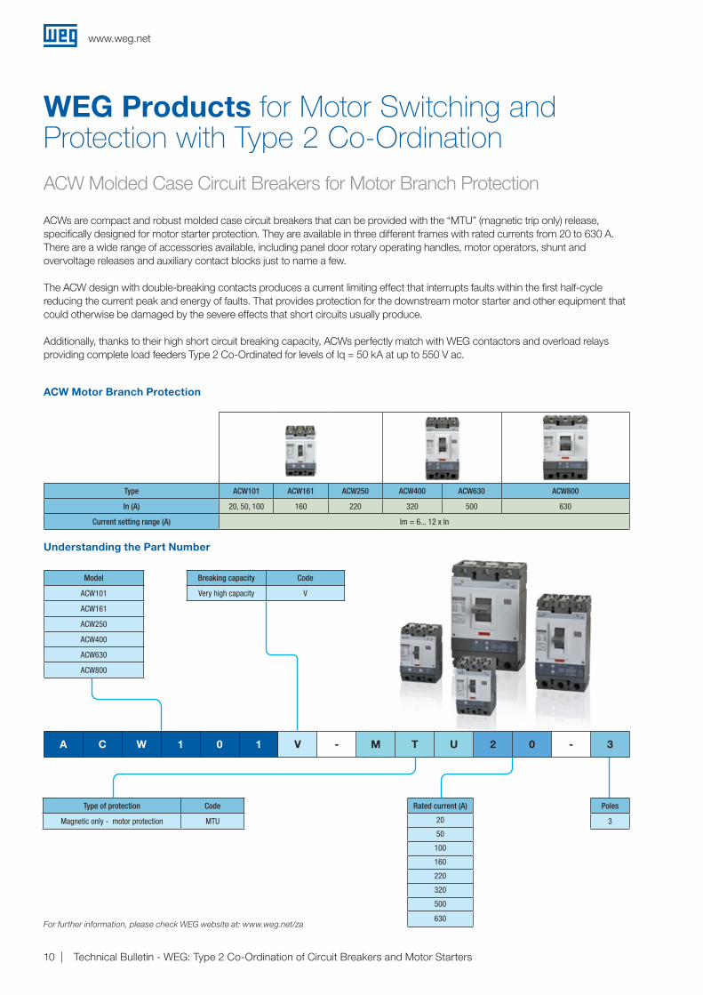
ACW Molded Case Circuit Breakers for Motor Branch Protection
WEG Products for Motor Switching and Protection with Type 2 Co-Ordination
ACWs are compact and robust molded case circuit breakers that can be provided with the “MTU” (magnetic trip only) release, specifically designed for motor starter protection. They are available in three different frames with rated currents from 20 to 630 A. There are a wide range of accessories available, including panel door rotary operating handles, motor operators, shunt and overvoltage releases and auxiliary contact blocks just to name a few.
The ACW design with double-breaking contacts produces a current limiting effect that interrupts faults within the first half-cycle reducing the current peak and energy of faults. That provides protection for the downstream motor starter and other equipment that could otherwise be damaged by the severe effects that short circuits usually produce.
Additionally, thanks to their high short circuit breaking capacity, ACWs perfectly match with WEG contactors and overload relays providing complete load feeders Type 2 Co-Ordinated for levels of Iq = 50 kA at up to 550 V ac.
ACW Motor Branch Protection
Understanding the Part Number
Type ACW101 ACW161 ACW250 ACW400 ACW630 ACW800
In (A) 20, 50, 100 160 220 320 500 630
Current setting range (A) Im = 6... 12 x In
A C W 1 0 1 V - M T U 2 0 - 3
Model
ACW101
ACW161
ACW250
ACW400
ACW630
ACW800
Breaking capacity Code
Very high capacity V
Type of protection Code
Magnetic only - motor protection MTU
Poles
3
Rated current (A)
20
50
100
160
220
320
500
630For further information, please check WEG website at: www.weg.net/za

www.weg.net
Technical Bulletin - WEG: Type 2 Co-Ordination of Circuit Breakers and Motor Starters 11
The MPW40 motor protective circuit breaker (MPCB) is a thermal-magnetic circuit breaker that combines in a single compact unit, the short circuit and isolation functionality of a MCCB with the motor overcurrent protection of a traditional tripping class-10 overload relay. When used along with a suitable contactor (the switching component), these two components comprise a complete and cost effective solution for motor starting and protection. The circuit breaker is definitely the component most affected by short circuit currents. Thus, maybe because of the compact size of the MPCBs, in the past there was a lack of confidence in these components, particularly when compared to bulky MCCBs.Indeed, MCCBs are really robust but years of research joined to technological development in many engineering fields led the MPCBs to become as reliable as any MCCB and now, MPCB’s compact size is considered a great advantage. An additional and important attribute of MPCBs with respect to effective short circuit protection is their low energy let-through values (the magnitude of the cut-off current and let-through energy in relation to the prospective short circuit current).In a few words, the MPW40 is a very limiting component and the stress of downstream contactors in the event of a short circuit is significantly reduced.
MPW40 Thermal and Magnetic Motor-Protective Circuit Breakers
M P W 4 0 - 3 - D 0 6 3
Model
MPW40
Code related to the setting of the overload release
Main contacts Code
3NO 3
Complete part numberCurrent range of the
overload release (A)
MPW40-3-C016 0,10 ... 0,16
MPW40-3-C025 0,16 ... 0,25
MPW40-3-D004 0,25 ... 0,40
MPW40-3-C063 0,40 ... 0,63
MPW40-3-U001 0,63 ... 1,0
MPW40-3-D016 1,0 ... 1,6
MPW40-3-D025 1,6 ... 2,5
MPW40-3-U004 2,5 ... 4,0
MPW40-3-D063 4,0 ... 6,3
MPW40-3-U010 6,3 ... 10
MPW40-3-U016 10 ... 16
MPW40-3-U020 16 ... 20
MPW40-3-U025 20 ... 25
MPW40-3-U032 25 ... 32
MPW40-3-U040 32 ... 40
For further information, please check WEG website at: www.weg.net/za
� With overload and short circuit protection � Fixed short circuit release 13 x lu � With phase-failure sensitivity according to IEC 60947-4-1 � With temperature compensation
� For use as main switch (IEC 60947-2) � Rotary handle operated � For use as main switch
Understanding the Part Number

www.weg.net
Technical Bulletin - WEG: Type 2 Co-Ordination of Circuit Breakers and Motor Starters12
CWM and CWB Contactors
WEG CWB and CWM lines of contactors are suitable for the use on applications where Type 2 Co-Ordination is required. This accomplishment results from the fact that, in order to withstand high transient currents that short circuits usually produce, WEG contactors have undergone several optimizations in the past five years.
Even though the transient phenomenon only occurs in a semi-cycle of the current, a huge amount of thermal energy is dissipated. This way the most important and effective improvements have been the reduction of contact resistance and improvement on the insulation of the contactor frame. In order to do so, several components have been improved and it has been necessary to optimize the design so as to increase the magnetic forces and, in some cases, even increase contact spring forces. All optimizations have been carried out with the commitment to obtaining the desired improvements without reducing mechanical and electrical lifespan or increasing contactor’s coil consumption.
C W M 1 0 5 T2 - 1 0 - 3 0 - D 2 4
Understanding the Part Number
Model
CWM
CWB
Ie AC-3 (A)Ue ≤ 440 V ac Ue = 525/550 V ac
CWB9 9 8CWB12 12 10CWB18 18 15CWB25 25 21CWB32 32 26CWB38 38 26
CWM50 T2 50 36CWM65 T2 65 51CWM80 T2 80 58CWM95 T2 95 73CWM105 T2 105 79
CWM112 112 90CWM150 150 122CWM180 180 147CWM250 250 207CWM300 300 248
Main contacts Code
3N0 30
Rated current In (AC-3) Code
9 A 9
12 A 12
18 A 18
25 A 25
32 A 32
38 A 38
50 A 50 T2
65 A 65 T2
80 A 80 T2
95 A 95 T2
105 A 105 T2
112 A 112
150 A 150
180 A 180
250 A 250
300 A 300
Auxiliary contacts Code
1N0 10
1NC 01
1N0+1NC 11
2N0+2NC 22
Coil voltage Code
24 V 50/60 Hz D02
110 V 50/60 Hz D13
230 V 50/60 Hz D24
24 V dc C03
Other coil voltages available upon request.
Other auxiliary contact configurations available upon request
For further information, please check WEG website at: www.weg.net/za

www.weg.net
Technical Bulletin - WEG: Type 2 Co-Ordination of Circuit Breakers and Motor Starters 13
Other popular SRW01 accessories include:Connection Cables, Earth Leakage Sensors, Digital Expansion Units, Human Machine Interfaces, Communication Modules, busbars for UMC and UMCT, among others.
For further information, please check WEG website at www.weg.net/za
SRW01 - Smart Solid State Overload Relay
Communication: Reliability on Motor Control and Protection Taken Even Further
Designed for use with motors ranging from 0.25 A to 5,000 A, the SRW01 is a reliable motor management system with state-of-the-art technology and flexible network communication capabilities.
The SRW01 offers comprehensive protection and monitoring functions. Major protection features include overload, thermistor monitoring, phase loss, over/under current and earth leakage, while the monitoring capabilities check the status of digital inputs and outputs, current for each phase, voltage, power factor, running hours and the number of starts of the system.
Thanks to SRW01, users can integrate Type 2 Co-Ordinated motor feeders to their plant management systems for remote monitoring and control. The remotely monitored parameters make possible to anticipate defects, aiding maintenance plans and reducing undesired downtime.
Major applications include intelligent motor control centers and continuous process plants.
Besides the overload protection, the SRW01 features network communication capabilities (Modbus, DeviceNet, Profibus).
Current Measuring Unit (UMC) or Current and Voltage Measuring Unit (UMCT)
A measuring unit should always be used along with the control unit.
Understanding the Part Number
Smart Relay - Control Unit
Current range (A) Current Measuring (UMC) Current and Voltage Measuring (UMCT)
0.5 ... 5 SRW01-UMC1 SRW01-UMCT1
1.25 ... 12.5 SRW01-UMC2 SRW01-UMCT2
2.5 ... 25 SRW01-UMC3 SRW01-UMCT3
12.5 ... 125 SRW01-UMC4 SRW01-UMCT4
42 ... 420 SRW01-UMC5 SRW01-UMCT5
84 ... 840 SRW01-UMC6 SRW01-UMCT6
S R W 0 1 - U C P T 1 E 4 7
Communicationprotocol Code
No communication B
DeviceNet D
Modbus-RTU M
Profibus-DP P
Protection Code
PTC T
Earth leakage E
Digital inputoperating voltage Code
24 V dc 1
110 V ac 2
Supply voltage Code
24 V ac (50-60 Hz) / V dc 1
110-240 V ac (50-60 Hz) / V dc 2

www.weg.net
Technical Bulletin - WEG: Type 2 Co-Ordination of Circuit Breakers and Motor Starters14
RW Thermal Bimetallic Overload Relays
RW thermal overload relays have been designed to be combined with CWM contactors to assemble motor starters. These reliable devices protect electric motors, controllers and branch circuit conductors against phase failures and overloads that may cause excessive heating. On thermal overload relays, the motor heating is simulated by passing motor current directly or indirectly through bimetal strips. The heat generated by joule effect (i²t) bends the bimetallic strips and, depending on the current set on the relay, a trip mechanism is activated. In order to comply with the Type 2 test requirements, the tripping of the overload relay shall be verified at a multiple of the current setting and shall conform to the published tripping characteristics, both before and after the short circuit test.
� Thermal overload relays tripping class 10 � With phase-failure sensitivity according to IEC 60947-4-1 � Auxiliary contacts 1NO + 1NC � With temperature compensation � Hand/Auto/Reset button
R W 1 1 7 - 2 D 3 - U 0 8 0
Model
RW67
RW117
RW317
Number of poles
3
Code related to the setting of the overload releaseCode related to the type of connection terminals
Complete part numberCurrent range of the
overload release (A)
RW67-2D3-U040 25 ... 40
RW67-2D3-U057 40 ... 57
RW67-2D3-U063 50 ... 63
RW67-2D3-U070 57 ... 70
RW67-2D3-U080 63 ... 80
RW117-2D3-U080 63 ... 80
RW117-2D3-U097 75 ... 97
RW117-2D3-U112 90 ... 112
RW317-1D3-U150 100 ... 150
RW317-1D3-U215 140 ... 215
For further information, please check WEG website at: www.weg.net/za
Understanding the Part Number

www.weg.net
Technical Bulletin - WEG: Type 2 Co-Ordination of Circuit Breakers and Motor Starters 15
References
IEC 60947-1 - Low-voltage switchgear and controlgear - Part 1: General Rules IEC 60947-4-1 - Low-voltage switchgear and controlgear - Part 4-1: Contactors and motor-starters - Electromechanical contactors and motor-starters.
IEC 60947-2 - Low-voltage switchgear and controlgear - Part 2: Circuit-breakers.
Jakov Vico; Rich Hunt, - Protection principles for electrical motors in the cement industry, 2010 IEEE-IAS/PCA 52nd Cement Industry Technical Conference, April 2010.

Cod
: 50
0692
32 |
Rev
: 00
| Dat
e (m
/y):
08/2
016
The
valu
es s
how
n ar
e su
bje
ct to
cha
nge
with
out p
rior
notic
e.
WEG Worldwide Operations
WEG Group - Automation Business Unit Jaraguá do Sul - SC - Brazil Phone: +55 47 3276 4000 [email protected] www.weg.net
For those countries where there is not a WEG own operation, find our local distributor at www.weg.net.
ARGENTINASan Francisco - CordobaPhone: +54 3564 [email protected]
Cordoba - CordobaPhone: +54 351 [email protected]
Buenos AiresPhone: +54 11 [email protected]
AUSTRALIAScoresby - Victoria Phone: +61 3 [email protected]
AUSTRIAMarkt Piesting - Wiener Neustadt-LandPhone: +43 2633 [email protected]
BELGIUMNivelles - BelgiumPhone: +32 67 [email protected]
BRAZILJaraguá do Sul - Santa CatarinaPhone: +55 47 [email protected]
CHILELa Reina - SantiagoPhone: +56 2 [email protected]
CHINANantong - JiangsuPhone: +86 513 [email protected]
Changzhou – Jiangsu Phone: +86 519 [email protected]
COLOMBIASan Cayetano - BogotaPhone: +57 1 [email protected]
ECUADOREl Batan - QuitoPhone: +593 2 [email protected]
FRANCESaint-Quentin-Fallavier - IsèrePhone: +33 4 [email protected]
GERMANYTürnich - Kerpen Phone: +49 2237 [email protected]
Balingen - Baden-WürttembergPhone: +49 7433 [email protected]
Homberg (Efze) - HessePhone: +49 5681 [email protected]
GHANAAccraPhone: +233 30 [email protected]
INDIABangalore - KarnatakaPhone: +91 80 [email protected]
Hosur - Tamil NaduPhone: +91 4344 [email protected]
ITALYCinisello Balsamo - MilanoPhone: +39 2 [email protected]
JAPANYokohama - KanagawaPhone: +81 45 [email protected]
MALAYSIAShah Alam - SelangorPhone: +60 3 [email protected]
MEXICOHuehuetoca - MexicoPhone: +52 55 [email protected]
Tizayuca - HidalgoPhone: +52 77 97963790
NETHERLANDSOldenzaal - OverijsselPhone: +31 541 [email protected]
PERULa Victoria - LimaPhone: +51 1 [email protected]
PORTUGALMaia - PortoPhone: +351 22 [email protected]
RUSSIA and CISSaint PetersburgPhone: +7 812 363 [email protected]
SOUTH AFRICAJohannesburgPhone: +27 11 [email protected]
SPAINCoslada - MadridPhone: +34 91 [email protected]
SINGAPORESingaporePhone: +65 [email protected]
SingaporePhone: +65 [email protected]
SCANDINAVIAMölnlycke - SwedenPhone: +46 31 [email protected]
UKRedditch - WorcestershirePhone: +44 1527 [email protected]
UNITED ARAB EMIRATESJebel Ali - DubaiPhone: +971 4 [email protected]
USADuluth - GeorgiaPhone: +1 678 [email protected]
Minneapolis - MinnesotaPhone: +1 612 3788000
VENEZUELAValencia - CaraboboPhone: +58 241 [email protected]