Embed Size (px)
Citation preview

LT1256X1 • 5/21/02 Serial Number
Type FB1300 & FB1400Furnaces
OPERATION AND REPAIR MANUALAND PARTS LIST
SERIES 1256 & 1257
Model NumbersFB1310M, FB1310M-26, FB1314M, FB1315M, FB1318M,FB1310M-33FB1410M, FB1410M-26, FB1414M, FB1415M, FB1418M, FB1410M-33
2
Table of Contents
Safety Information ..............................................................................................................................................3Important Information....................................................................................................................................3Warnings ......................................................................................................................................................4
Introduction..........................................................................................................................................................5Intended Use ................................................................................................................................................5General Usage..............................................................................................................................................5Principles of Operation ................................................................................................................................5
General Specifications ........................................................................................................................................6Declaration of Conformity ............................................................................................................................7
Unpacking ..........................................................................................................................................................8Installation ..........................................................................................................................................................9
Site Selection................................................................................................................................................9Electrical Connections ..................................................................................................................................9
Operation ..........................................................................................................................................................10Power Switch ..............................................................................................................................................10Cycle Light ..................................................................................................................................................10Door Safety Switch ....................................................................................................................................10
Single Setpoint Controller ................................................................................................................................10Basic Operation ..........................................................................................................................................11Buttons and Indicators ................................................................................................................................11To View or Change the Setpoint ................................................................................................................12To View the Display Units ..........................................................................................................................12To View the % Output Power......................................................................................................................12Controller Parameters ................................................................................................................................12Alarms ........................................................................................................................................................13Sensor Break Protection ............................................................................................................................14Overt Temperature Protection (OTP)..........................................................................................................14Tuning ........................................................................................................................................................14
Furnace Loading ..............................................................................................................................................16Preventive Maintenance....................................................................................................................................17Troubleshooting ................................................................................................................................................18Maintenance and Servicing ..............................................................................................................................19
To Replace Heating Element ......................................................................................................................19To Replace Thermocouple..........................................................................................................................22To Replace Insulation ................................................................................................................................23To Replace Door Switches ........................................................................................................................25To Replace Solid State Relay ....................................................................................................................26To Replace PC Board (Controller) ..............................................................................................................26
Wiring Diagram..................................................................................................................................................27Exploded View ................................................................................................................................................28Replacement Parts List ....................................................................................................................................30Ordering Procedures ........................................................................................................................................31One Year Limited Warranty ..............................................................................................................................32
3
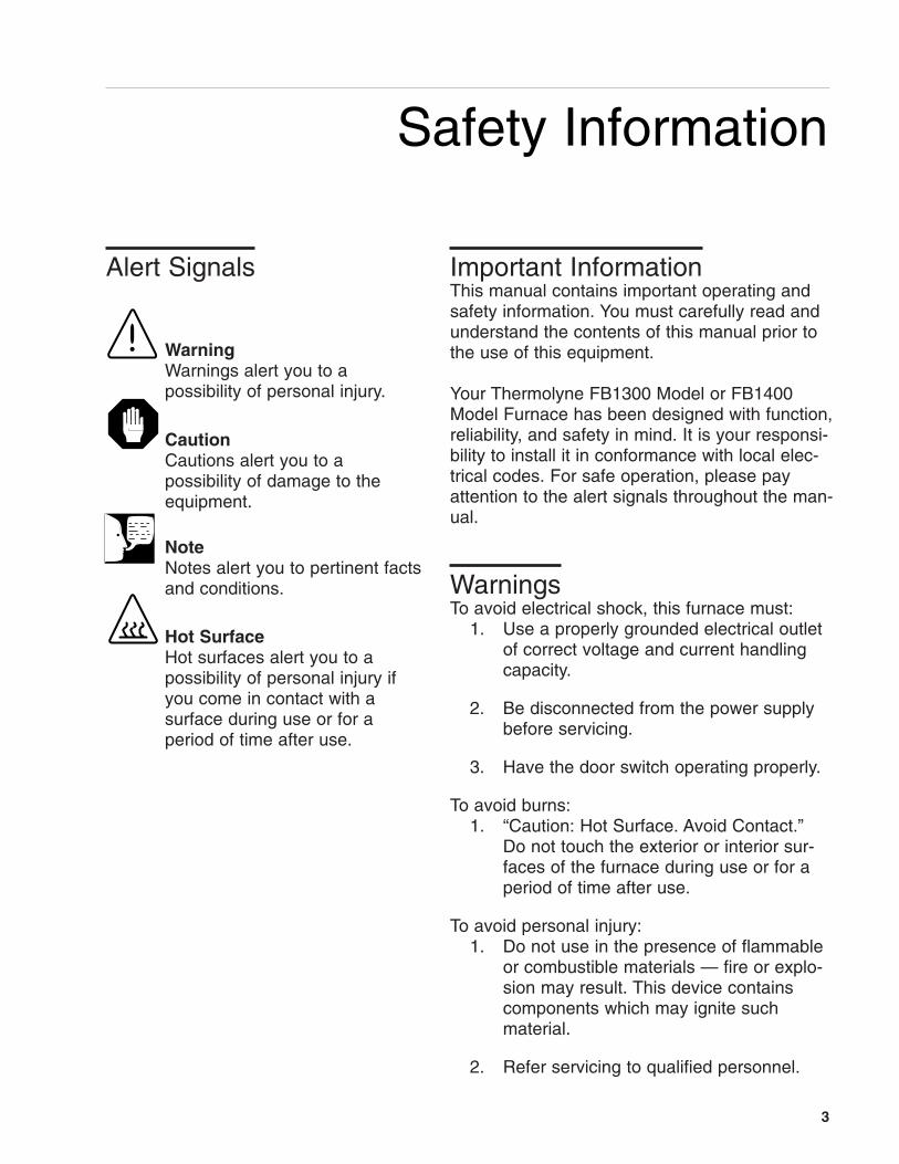
Important InformationThis manual contains important operating andsafety information. You must carefully read andunderstand the contents of this manual prior tothe use of this equipment.
Your Thermolyne FB1300 Model or FB1400Model Furnace has been designed with function,reliability, and safety in mind. It is your responsi-bility to install it in conformance with local elec-trical codes. For safe operation, please payattention to the alert signals throughout the man-ual.
WarningsTo avoid electrical shock, this furnace must:
1. Use a properly grounded electrical outletof correct voltage and current handlingcapacity.
2. Be disconnected from the power supplybefore servicing.
3. Have the door switch operating properly.
To avoid burns:1. “Caution: Hot Surface. Avoid Contact.”
Do not touch the exterior or interior sur-faces of the furnace during use or for aperiod of time after use.
To avoid personal injury:1. Do not use in the presence of flammable
or combustible materials — fire or explo-sion may result. This device containscomponents which may ignite suchmaterial.
2. Refer servicing to qualified personnel.
Safety Information
WarningWarnings alert you to a possibility of personal injury.
CautionCautions alert you to a possibility of damage to theequipment.
NoteNotes alert you to pertinent factsand conditions.
Hot SurfaceHot surfaces alert you to a possibility of personal injury ifyou come in contact with a surface during use or for a period of time after use.
Alert Signals
4
Please note the following WARNINGS:
WARNING
This warning is presented for compliance with California Proposition 65 and other regulato-ry agencies and only applies to the insulation in this product. This product contains refracto-ry ceramic, refractory ceramic fiber or fiberglass insulation, which can produce respirabledust or fibers during disassembly. Dust or fibers can cause irritation and can aggravatepreexisting respiratory diseases. Refractory ceramic and refractory ceramic fibers (afterreaching 1000°C) contain crystalline silica, which can cause lung damage (silicosis). TheInternational Agency for Research on Cancer (IARC) has classified refractory ceramic fiberand fiberglass as possibly carcinogenic (Group 2B), and crystalline silica as carcinogenic tohumans (Group 1).
The insulating materials can be located in the door, the hearth collar, in the chamber of theproduct or under the hot plate top. Tests performed by the manufacturer indicate that thereis no risk of exposure to dust or respirable fibers resulting from operation of this productunder normal conditions. However, there may be a risk of exposure to respirable dust orfibers when repairing or maintaining the insulating materials, or when otherwise disturbingthem in a manner which causes release of dust or fibers. By using proper handling proce-dures and protective equipment you can work safely with these insulating materials andminimize any exposure. Refer to the appropriate Material Safety Data Sheets (MSDS) forinformation regarding proper handling and recommended protective equipment. For addi-tional MSDS copies, or additional information concerning the handling of refractory ceramicproducts, please contact the Customer Service Department at Barnstead International at 1-800-553-0039.
SAFETY INFORMATION

5
Intended UseThe FB1300 Model and FB1400 Model fur-naces are general purpose laboratory and heattreating furnaces. For optimum element life,observe the following temperature ranges:100°C (212°F) to 982°C (1800°F) for continuoususe, or from 982°C (1800°F) to 1100°C(2012°F) for intermittent use. Continuous use isoperating the furnace for more than threestraight hours, and intermittent use is operatingthe furnace for less than three hours.
The unit consists of a heating chamber and adigital controller. See Figure 1 for the overallshape and general features of the unit.
General UsageDo not use this product for anything other thanits intended usage.
Principles of OperationThe furnace chamber is heated by a singlethree section resistant heater which is embed-ded in a refractory material. The chamber isinsulated with a ceramic fiber insulation. Thetemperature is controlled by an electronic con-trol. The temperature is measured by a thermo-couple and is registered on a digital display. Forsafety, door switches are incorporated toremove power from the heating elements whenthe door is opened. The furnace is supported bythe control section which also houses the elec-trical connections.
Introduction

66
General SpecificationsFB1300 Models Dimensions: (handle not included)Chamber: 4” W x 3.75” H x 4.5” D (10.2 x 9.5 x 11.4 cm)Overall : 7.9” W x 13.8” H x 8.5” D (20.0 x 34.9 x 21.6 cm)Weight: 15.7 lb. (7.1 kg)Electrical Ratings:Model # Volts Amps Watts Phase FrequencyFB1310M 220-240 4.4 1060 1 50/60FB1310M-26 220-240 4.4 1060 1 50/60FB1310M-33 220-240 4.4 1060 1 50/60FB1314M 100 10.6 1060 1 50/60FB1315M 120 8.9 1060 1 50/60FB1318M 208 5.1 1060 1 50/60Temperature: Operating Range (continuous): 982°C; (intermittent): 1100°C.
Environmental Conditions:Operating: 17°C - 27°C; 20% - 80% relative humidity, non-condensing. Installation Category II (over-voltage) in accordance with IEC 664. Pollution Degree 2 in accordance with IEC 664. Altitude limit: 2,000 meters.Storage: -25°C - 65°C; 20% - 80% relative humidity.
FB1400 Models
Dimensions: (handle not included)Chamber: 5.00” W x 4.25” H x 6.00” D (12.7 x 10.8 x 15.2 cm)Overall: 9.7” W x 15.8” H x 11.1” D (24.6 x 39.0 x 28.3 cm)Weight: 23 lb. (10.4 kg)Electrical Ratings:Model # Volts Amps Watts Phase FrequencyFB1410M 220-240 6.3 1520 1 50/60FB1410M-26 220-240 6.3 1520 1 50/60FB1410M-33 220-240 6.3 1520 1 50/60FB1414M 100 14.5 1520 1 50/60FB1415M 120 12 1450 1 50/60FB1418M 208 7.3 1520 1 50/60Temperature: Operating Range (continuous): 982°C; (intermittent): 1100°C.
Environmental Conditions:Operating: 17°C - 27°C; 20% - 80% relative humidity, non-condensing. Installation Category II (over-voltage) in accordance with IEC 664. Pollution Degree 2 in accordance with IEC 664. Altitude limit: 2,000 meters.Storage: -25°C - 65°C; 20% - 80% relative humidity.

7
Declaration of ConformityBarnstead International hereby declares under its soleresponsibility that this product conforms with the techni-cal requirements of the following standards (-33 modelsonly):
EMC: EN 50081-1 Generic Emission Standard; EN 50082-1 Generic Immunity Standard.
Safety: EN 1010-1-92 Safety requirements for electrical equipment for measurement,control and laboratory use; Part I: General Requirements
EN 1010-2-010 Part II: Particular requirements for laboratory equipment for theheating of materials
per the provisions of the Electromagnetic CompatibilityDirective 89/336/EEC, as amended by 92/31/EEC and93/68/EEC, and per the provisions of the Low VoltageDirective 73/23/EEC, as amended by 93/68/EEC.
The authorized representative located within theEuropean Community is:
Electrothermal Engineering, Ltd.419 Sutton RoadSouthend On SeaEssex SS2 5PHUnited Kingdom
Copies of the Declaration of Conformity are availableupon request.
GENERAL SPECIFICATIONS
8
Unpacking
1. Visually check for any physicaldamage to the shipping container.
2. Inspect the equipment surfaces thatare adjacent to any damaged area.
3. Open the furnace door and removethe packing material from inside thefurnace chamber.
4. Vacuum the chamber prior to use toremove the insulation dust due toshipment.
5. Retain the original packaging mate-rial if reshipment is foreseen orrequired.
9
Installation
CautionBe sure ambient temperature doesnot exceed 40°C (104°F). The rec-ommended ambient temperature is17°C - 27°C. Ambients above thislevel may result in damage to thecontroller.
CautionAllow at least six inches of spacebetween the furnace and any com-bustible surface. This permits theheat from the furnace case toescape so as not to create a pos-sible fire hazard.
WarningTo avoid electrical shock, this fur-nace must always use a properlygrounded outlet of correct voltageand current handling capacity.
Site SelectionInstall furnace on a sturdy surface and allowadequate space for ventilation.
Electrical ConnectionsThe electrical ratings are located on the spec-ification plate on the back of the furnace.Consult Barnstead International if your electri-cal service is different than those listed on thespecification plate. Be sure the front powerswitch is in the OFF position before connect-ing the furnace to your electrical supply.

10
Operation, All Modes
WarningTo avoid personal injury do not usein the presence of flammable orcombustible chemicals; fire orexplosion may result. This devicecontains components which mayignite such materials.
Hot SurfaceCaution: Avoid Contact. To avoidburns, this furnace must not betouched on the exterior or interiorsurfaces during use or for a periodof time after use.
WarningTo avoid electrical shock, the doorsafety switch must be operating properly.
WarningAlways wear safety glasses or asafety shield and high temperaturegloves when loading or unloadingthe furnace. Long sleeved, fireretardant clothing and a fire retar-dant apron is also recommended.
Power SwitchBoth the ON/OFF power switch and the digitaldisplay will illuminate when power is switchedON. The furnace will begin to heat to the con-troller's current setpoint. (See the instructionsfor your type of controller for information onchecking and setting the setpoint.)
Cycle LightThe amber cycle light will illuminate wheneverthe power is being applied to the heating ele-ments. The cycle light will turn on and off asthe furnace reaches the setpoint.
Door Safety SwitchThe door safety switch removes power fromthe heating elements when the door isopened. Open and close the door a fewtimes; note that the amber CYCLE light willswitch off when the door is opened. If thiscondition is not true, consult theTroubleshooting section before proceeding.This check must be done when the furnace isheating and the cycle light is illuminated.
Single Setpoint Controller
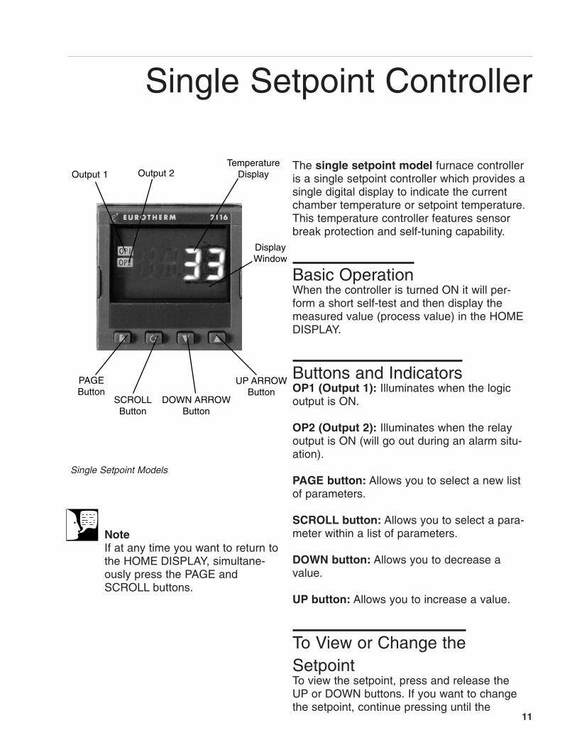
Output 1
UP ARROW Button
Temperature Display
Display Window
DOWN ARROWButton
PAGE Button
SCROLLButton
Output 2
NoteIf at any time you want to return tothe HOME DISPLAY, simultane-ously press the PAGE andSCROLL buttons.
Single Setpoint Models
The single setpoint model furnace controlleris a single setpoint controller which provides asingle digital display to indicate the currentchamber temperature or setpoint temperature.This temperature controller features sensorbreak protection and self-tuning capability.
Basic OperationWhen the controller is turned ON it will per-form a short self-test and then display themeasured value (process value) in the HOMEDISPLAY.
Buttons and IndicatorsOP1 (Output 1): Illuminates when the logicoutput is ON.
OP2 (Output 2): Illuminates when the relayoutput is ON (will go out during an alarm situ-ation).
PAGE button: Allows you to select a new listof parameters.
SCROLL button: Allows you to select a para-meter within a list of parameters.
DOWN button: Allows you to decrease avalue.
UP button: Allows you to increase a value.
To View or Change theSetpointTo view the setpoint, press and release theUP or DOWN buttons. If you want to changethe setpoint, continue pressing until the
11
12
SINGLE SETPOINT CONTROLLER
desired setpoint value is displayed and thenrelease the button. A few seconds after the buttonis released, the controller will accept the newvalue and revert to the HOME DISPLAY.
To View the Display UnitsFrom the HOME DISPLAY press the SCROLLbutton. The display will show the temperatureunits in °C/F/K and then return to the HOME DIS-PLAY. (Call Customer Service if you require a dif-ferent temperature unit.)
To View the % Output PowerFrom the HOME DISPLAY press the SCROLLbutton twice. Press and release the UP or DOWNbutton to view the % output power. This value is aread-only value and cannot be changed.
Controller Parameters
Home display°C: Temperature units in Celsius. Temperatureunits can not be changed without entering theconfiguration. Contact Customer Service if a dif-ferent temperature unit is required.OP: % output power demand.
IdHi: Deviation high alarm.
Al ListIdHi: Deviation high alarm.

13
SINGLE SETPOINT CONTROLLER
Atun ListtunE: One-shot autotune enable.
Pid ListPb: Proportional band (in display units).
ti: Integral time in seconds.
td: Derivative time in seconds.
ACCS List Code: Access code (Code need-ed to enter or change the other configurationparameters which are not normally accessi-ble.) Not accessable.
AlarmsThe controller will flash an alarm message inthe home display if an alarm condition isdetected.
2FSH: Measured value full scale high alarm.
IdHi: Measured value deviation high alarm.
S.br: Sensor break: check that sensor is con-nected correctly.
L.br: Loop break: check that the heating cir-cuits are working properly.
Ld.F: Heater Circuit fault: indication of eitheran open or short solid sate relay, a blownfuse, missing supply or open circuit heater.
NoteThe following alarm messagesare factory default settings andmay vary if you have changedthe configuration of your controller:
IDHi: = 50°C2FSH = 1125°C
14
SINGLE SETPOINT CONTROLLER
Sensor Break ProtectionThis controller provides sensor break protection inthe event the thermocouple opens. If an open ther-mocouple condition occurs, the digital display willblink “S.br” and the power to the heating elementwill be shut OFF (Cycle light will extinguish).
Over-Temperature Protection(OTP)The OTP will be in effect during any alarm condi-tion when the temperature of the furnace has devi-ated beyond the limit. The “Deviation High” alarm isthe only alarm value which can be changed. Tochange it, press the SCROLL button until “IdHi”appears on the display. Press the UP or DOWNbutton to select the OTP value you desire. We rec-ommend a value of 20° above your working tem-perature to provide protection for your workload.
TuningThis controller incorporates a self-tuning featurewhich determines the optimum control parametersfor the best temperature accuracy with your loadand setpoint. Use this feature the first time you useyour furnace and each time you change either yoursetpoint or the type of load you are heating.Barnstead|Thermolyne recommends you use thisfeature to provide the best temperature accuracythe controller can attain. To use the tuning feature:
1. Adjust the setpoint to your desired value.
2. Press the PAGE button until display reads,“Atun.”
NoteFurnace must be at ambient temperature before starting a tune.
15
SINGLE SETPOINT CONTROLLER
NoteTune has completed when “tunE”stops flashing on display.
3. Press the SCROLL button. Displaywill read, “tunE.”
4. Press the UP or DOWN button toselect, “on.”
5. Simultaneously press the PAGE andSCROLL buttons to return to theHOME DISPLAY. The display willalternately flash between “tunE” andthe HOME DISPLAY while tuning is inprogress.
6. The controller will then turn the heat-ing on and off to induce an oscillation.When the measured value reachesthe required setpoint the first cycle willend.
7. Tuning will be complete after twooscillation cycles and then the tunerwill turn itself off.
8. Normal control function will resumeafter the controller calculates tuningparameters.
16
• For best results of furnace loading, useless than two-thirds of any dimension ofthe chamber. Maintain a 3/4" clearancebetween the load and the sides of thechamber.
• If you are heating a number of smallparts, spread them throughout the mid-dle two thirds of the chamber.
• Keep objects away from thermocouple.
• Raise your load up off the furnace floorwith small pieces of ceramic or a hearthplate to promote even heating.
• Use insulated tongs and mittens whenloading and unloading furnace.
• Always wear safety glasses.
Furnace Loading
CautionDo not overload your furnacechamber or allow the load totouch the thermocouple. If theload is to be heated uniformly, itshould not occupy more thantwo-thirds of any dimension ofthe chamber. Failure to observethese cautions could result indamage to furnace componentsand/or load.

17
Preventive Maintenance
WarningBefore using any cleaning ordecontamination methodexcept those recommendedby Barnstead International,users should check withBarnstead International thatthe proposed method will notdamage the equipment.
WarningDisconnect the furnace frompower supply before clean-ing.
WarningOpening the door for anextended period of time willcause the painted surfacesabove the door to be discol-ored or burnt.
Contamination is a major cause of element failure,therefore, when possible, remove the fume formingmaterial before heating (e.g., cleaning cutting oilfrom tool steel).
The resistance wire is high-grade nickel-chromium.Some chemicals, notably sulphur, halogens, andcyanides, attack this wire at high temperatures, soavoid spilling these chemicals in the furnace orheating them any hotter than necessary. Therefractory cement helps to protect the wire, but willnot completely immunize it from damage.
All heating elements must be considered expend-able, and replacement is expected; however, rea-sonable care in their use will greatly extend the ser-vice they will give. As the manufacturer has no con-trol over the use or care of the elements, no specif-ic service guarantee can be made.
Housekeeping is vital to your electric furnace—KEEP IT CLEAN! Run your furnace up to 871°C(1600°F) empty occasionally to burn off the conta-mination that may exist on the insulation and ele-ments. Run for approximately two hours with thedoor slightly open. See warning.
Element life is reduced somewhat by repeatedheating and cooling. If the furnace is to be usedagain within a few hours, it is best to keep it at theoperating temperature or at a reduced level suchas 260°C (500°F).
During normal use, the thermocouple in your fur-nace can become oxidized and cause inaccuratereadings; therefore, we suggest that if you regularlyuse your furnace you should change your thermo-couple once every six months to assure the accura-cy of your controller readings.
Clean by wiping the outside case of the unit with adamp cloth and mild soap solution.
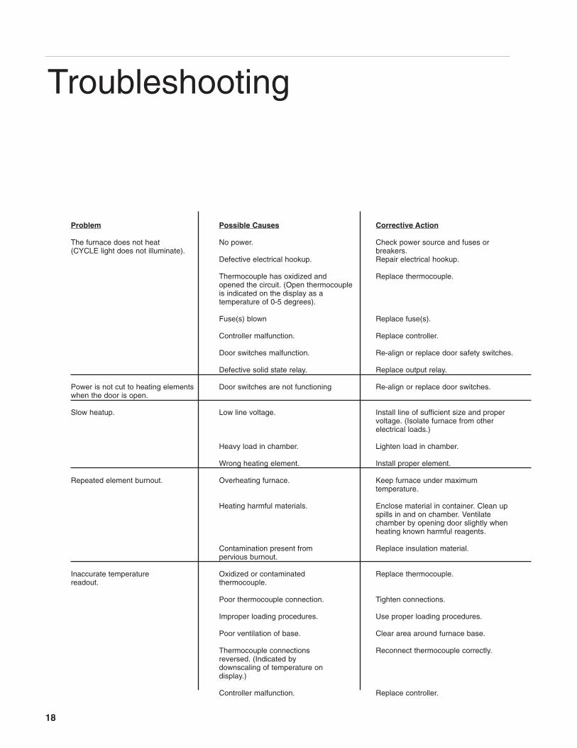
Problem Possible Causes Corrective Action
The furnace does not heat No power. Check power source and fuses or(CYCLE light does not illuminate). breakers.
Defective electrical hookup. Repair electrical hookup.
Thermocouple has oxidized and Replace thermocouple.opened the circuit. (Open thermocoupleis indicated on the display as a temperature of 0-5 degrees).
Fuse(s) blown Replace fuse(s).
Controller malfunction. Replace controller.
Door switches malfunction. Re-align or replace door safety switches.
Defective solid state relay. Replace output relay.
Power is not cut to heating elements Door switches are not functioning Re-align or replace door switches.when the door is open.
Slow heatup. Low line voltage. Install line of sufficient size and propervoltage. (Isolate furnace from otherelectrical loads.)
Heavy load in chamber. Lighten load in chamber.
Wrong heating element. Install proper element.
Repeated element burnout. Overheating furnace. Keep furnace under maximumtemperature.
Heating harmful materials. Enclose material in container. Clean upspills in and on chamber. Ventilatechamber by opening door slightly whenheating known harmful reagents.
Contamination present from Replace insulation material.pervious burnout.
Inaccurate temperature Oxidized or contaminated Replace thermocouple.readout. thermocouple.
Poor thermocouple connection. Tighten connections.
Improper loading procedures. Use proper loading procedures.
Poor ventilation of base. Clear area around furnace base.
Thermocouple connections Reconnect thermocouple correctly.reversed. (Indicated bydownscaling of temperature ondisplay.)
Controller malfunction. Replace controller.
18
Troubleshooting
19
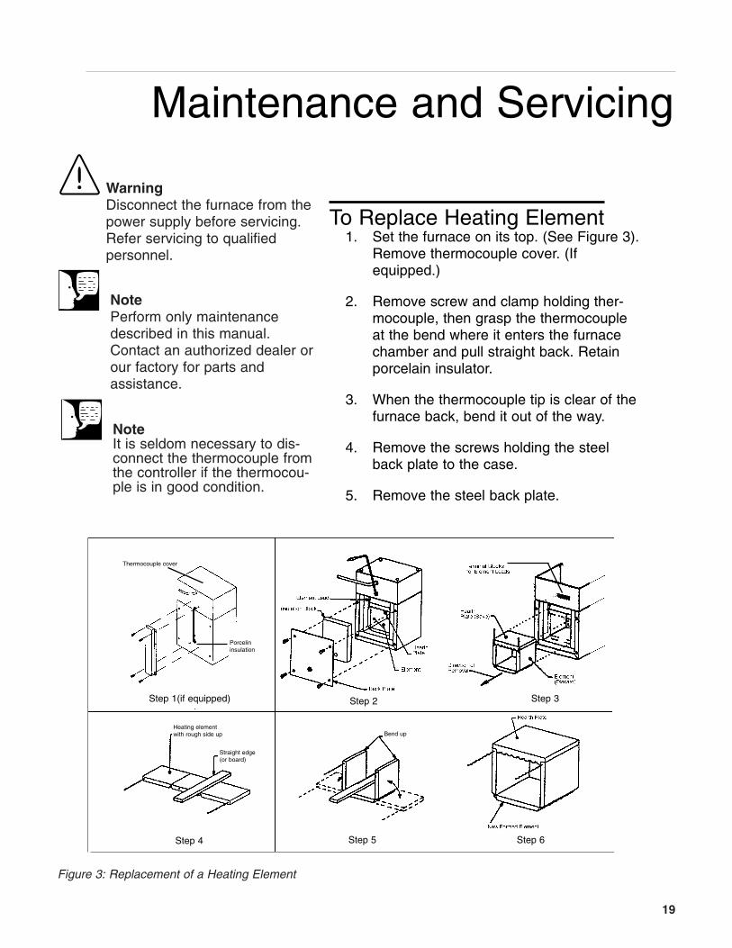
Figure 3: Replacement of a Heating Element
WarningDisconnect the furnace from thepower supply before servicing.Refer servicing to qualified personnel.
NotePerform only maintenancedescribed in this manual.Contact an authorized dealer orour factory for parts and assistance.
NoteIt is seldom necessary to dis-connect the thermocouple fromthe controller if the thermocou-ple is in good condition.
Step 1(if equipped)
Thermocouple cover
Porcelin insulation
Step 2 Step 3
Step 4 Step 5 Step 6
Heating element with rough side up
Straight edge(or board)
Bend up
Maintenance and Servicing
To Replace Heating Element1. Set the furnace on its top. (See Figure 3).
Remove thermocouple cover. (Ifequipped.)
2. Remove screw and clamp holding ther-mocouple, then grasp the thermocoupleat the bend where it enters the furnacechamber and pull straight back. Retainporcelain insulator.
3. When the thermocouple tip is clear of thefurnace back, bend it out of the way.
4. Remove the screws holding the steelback plate to the case.
5. Remove the steel back plate.
20
MAINTENANCE AND SERVICING
NoteThe hearth plate contains noheating coil, and may be savedfor re-installation if it is in goodcondition. The hearth plate isreplaceable independent of theheating element.
6. Remove the back insulation block by open-ing the door and gently pushing it out.Support this insulation block while removingit, as it is quite soft and easily crumbled atthe edges.
7. Remove bottom cover to obtain access toterminals.
These steps will expose the heating element leadsand insulating bushings in the bottom plate of thefurnace.
8. Cut the element leads between the elementand the terminal block. (There are twoleads.) The element and hearth plate unitmay now be removed by pushing it straightback out of the furnace. Use care not todamage the chamber insulation whenremoving the hearth plate and element as itcan be reused if it has not been contaminat-ed.
9. Remove the old element lead wire andpower wires from the terminal block, andsave the sleeving for re-installation on thenew element leads. Sleeving must bereplaced if cracked or brittle!
10. New elements are shipped flat to protectthem from damage in shipment, and to savespace in storage. They must be formedbefore installation.
11. Place the element on a flat surface with therough side up. Place a board or otherstraight edge along one row of notches.
12. Gently bend the element along the straightedge. The refractory cement will breakalong the row of notches.
21
MAINTENANCE AND SERVICING
NoteNicking or damaging the ele-ment leads will cause prema-ture element failure.
Make the bend 90°, avoiding excessive bend-ing. (The element wires will be exposed at thecorner thus formed. This will not affect its lifeor performance.)
13. Bend the other side of the element.
14. Place the hearth plate across the open end ofthe ‘’U” shaped element.
15. Slide the element and hearth plate unit intothe chamber, pushing it firmly against thehearth collar. Use care not to damage the softinsulation. Remove any crumbs of insulationthat may get between the unit and the hearthcollar.
16. Thread the element leads through the ceram-ic bushings. Bend the leads so they lie closeto the refractory plate and the bottom insula-tion block. (The easiest and safest way to dothis is to press the wire flat with a stick orblunt pusher. Do not use a sharp object ornick the wire.)
17. Replace the sleeving and bend the lead 3/4turn around the terminal screw. Cut off theexcess wire. Replace power wires on top ofelement lead wires and tighten screw. Do notcross the wire over itself around the terminal;this makes it difficult to keep the connectiontight and prevents good electrical contact. Ifyou have excess wire, cut it off. Make sureelement lead wires are not touching any otherwires.
18. Replace the back insulation block and backplate.
19. Examine the thermocouple, and, if it is good,reinsert it into the chamber. It should extend
22
MAINTENANCE AND SERVICING
WarningDisconnect the furnace from thepower supply before servicing.
about 1-1/2" into the chamber. Make sureporcelain insulator is in place for the ther-mocouple to pass through on the steelback plate. Replace clamp and screw.(Excessive scaling, pitting, or cracks aresome indications that the thermocouplemay need to be replaced.)
20. Replace bottom cover of control unit.
21. Replace thermocouple cover.
22. If replacement of back insulation is neces-sary, carefully redrill hole for thermocou-ple, using back cover as guide.
23. Reconnect furnace to power supply.
24. Test operation of furnace.
To Replace Thermocouple1. Set furnace on its top.
2. Remove thermocouple cover. (If equipped.)
3. Remove screw and clamp holding the ther-mocouple, then grasp the thermocouple atthe bend where it enters the chamber andpull it straight back from the furnace. Retainporcelain insulator.
4. Remove bottom cover.
5. Disconnect the thermocouple from the ter-minal block by removing the screws on theterminals. Pull the thermocouple throughthe hole in the furnace base and discard.
6. Insert the new thermocouple into the backof the furnace chamber. Make sure theporcelain insulator extends through thesteel back plate to prevent the lead wiresfrom touching metal.
NoteIf the thermocouple touches metal,this could short out the signal,causing the control to display roomtemperature. This could cause thefurnace temperature to run away,possibly damaging furnace compo-nents.
23
MAINTENANCE AND SERVICING
NoteIf the control temperature displaymoves downward, the thermo-couple leads are reversed.
7. Thread the thermocouple through the holein the base which has a nylon insulator,replace clamp and screw.
8. Bend the thermocouple sharply toward ter-minal block.
9. Secure the two yellow wires marked “+”together on the terminal block. Secure thetwo red wires “-” together on the adjacentterminal. Make sure connections are secureto terminal block.
A polarity test of the thermocouple and lead wire iseasily made with the use of a magnet. On chromelalumel thermocouples and lead wire, the non-mag-netic wire is positive ( + ) and the magnetic wire isnegative ( - ).
10. Replace bottom plate.
11. Replace thermocouple cover. (If equipped.)
12. Reconnect furnace to power supply.
13. Test operation of furnace.
To Replace Insulation1. Remove thermocouple cover. (If equipped.)
2. Set furnace on its top and remove screwand clamp securing thermocouple, thengrasp thermocouple and remove by pullingit straight back. Retain porcelain insulator.
3. Remove back plate.
4. Remove bottom cover.
5. Disconnect the element leads from terminalblock.
WarningDisconnect furnace from powersupply before servicing.
24
MAINTENANCE AND SERVICING
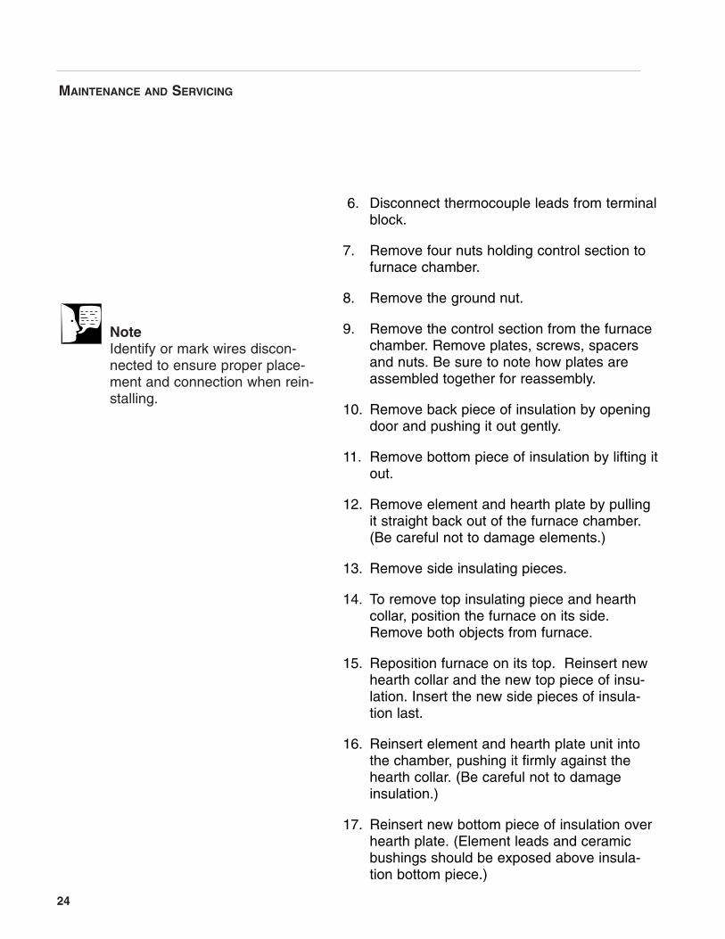
NoteIdentify or mark wires discon-nected to ensure proper place-ment and connection when rein-stalling.
6. Disconnect thermocouple leads from terminalblock.
7. Remove four nuts holding control section tofurnace chamber.
8. Remove the ground nut.
9. Remove the control section from the furnacechamber. Remove plates, screws, spacersand nuts. Be sure to note how plates areassembled together for reassembly.
10. Remove back piece of insulation by openingdoor and pushing it out gently.
11. Remove bottom piece of insulation by lifting itout.
12. Remove element and hearth plate by pullingit straight back out of the furnace chamber.(Be careful not to damage elements.)
13. Remove side insulating pieces.
14. To remove top insulating piece and hearthcollar, position the furnace on its side.Remove both objects from furnace.
15. Reposition furnace on its top. Reinsert newhearth collar and the new top piece of insu-lation. Insert the new side pieces of insula-tion last.
16. Reinsert element and hearth plate unit intothe chamber, pushing it firmly against thehearth collar. (Be careful not to damageinsulation.)
17. Reinsert new bottom piece of insulation overhearth plate. (Element leads and ceramicbushings should be exposed above insula-tion bottom piece.)
25
MAINTENANCE AND SERVICING
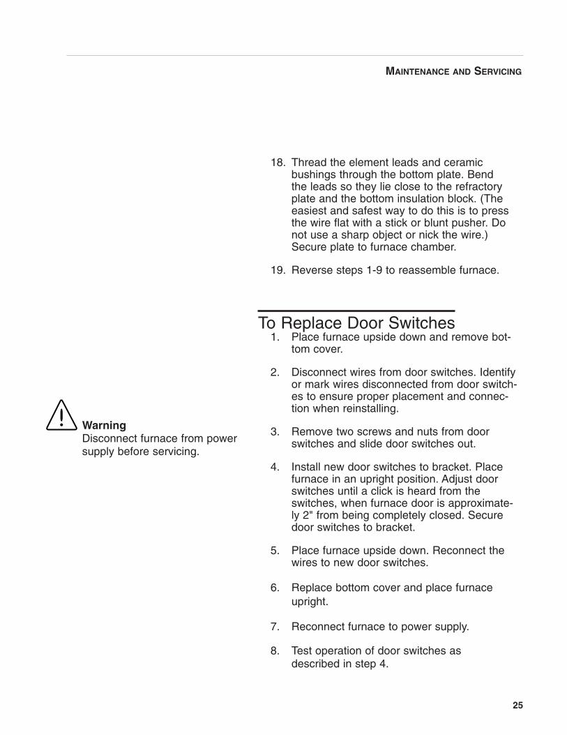
18. Thread the element leads and ceramicbushings through the bottom plate. Bendthe leads so they lie close to the refractoryplate and the bottom insulation block. (Theeasiest and safest way to do this is to pressthe wire flat with a stick or blunt pusher. Donot use a sharp object or nick the wire.)Secure plate to furnace chamber.
19. Reverse steps 1-9 to reassemble furnace.
To Replace Door Switches1. Place furnace upside down and remove bot-
tom cover.
2. Disconnect wires from door switches. Identifyor mark wires disconnected from door switch-es to ensure proper placement and connec-tion when reinstalling.
3. Remove two screws and nuts from doorswitches and slide door switches out.
4. Install new door switches to bracket. Placefurnace in an upright position. Adjust doorswitches until a click is heard from theswitches, when furnace door is approximate-ly 2" from being completely closed. Securedoor switches to bracket.
5. Place furnace upside down. Reconnect thewires to new door switches.
6. Replace bottom cover and place furnaceupright.
7. Reconnect furnace to power supply.
8. Test operation of door switches asdescribed in step 4.
WarningDisconnect furnace from powersupply before servicing.
26
MAINTENANCE AND SERVICING
WarningDisconnect furnace from powersupply before servicing.
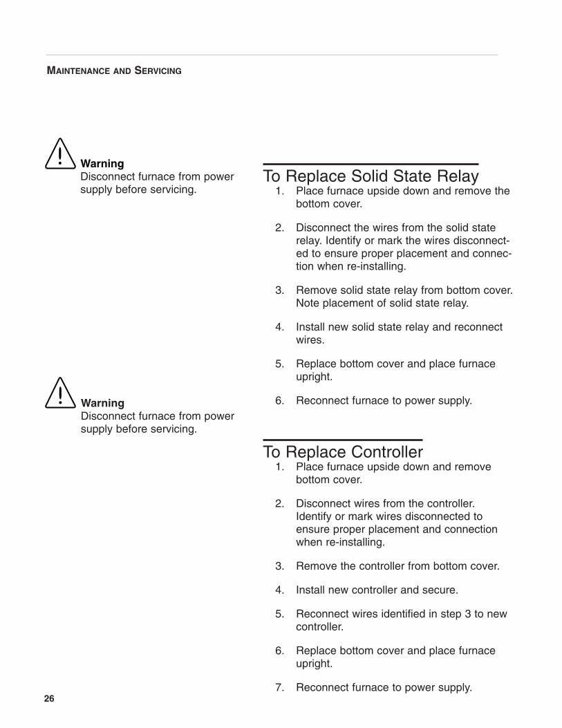
To Replace Solid State Relay1. Place furnace upside down and remove the
bottom cover.
2. Disconnect the wires from the solid staterelay. Identify or mark the wires disconnect-ed to ensure proper placement and connec-tion when re-installing.
3. Remove solid state relay from bottom cover.Note placement of solid state relay.
4. Install new solid state relay and reconnectwires.
5. Replace bottom cover and place furnaceupright.
6. Reconnect furnace to power supply.
To Replace Controller1. Place furnace upside down and remove
bottom cover.
2. Disconnect wires from the controller.Identify or mark wires disconnected toensure proper placement and connectionwhen re-installing.
3. Remove the controller from bottom cover.
4. Install new controller and secure.
5. Reconnect wires identified in step 3 to newcontroller.
6. Replace bottom cover and place furnaceupright.
7. Reconnect furnace to power supply.
WarningDisconnect furnace from powersupply before servicing.

27
Wiring DiagramsFB 1400 models
FB1300 models
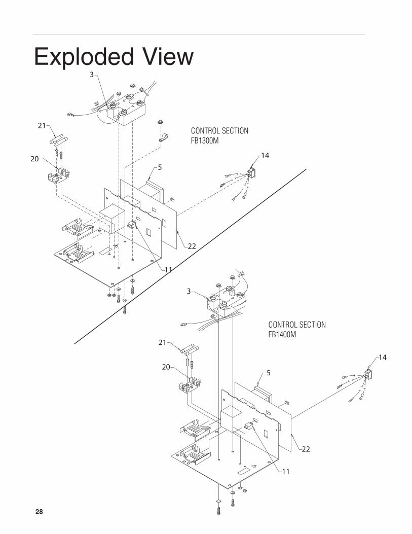
Exploded View
28
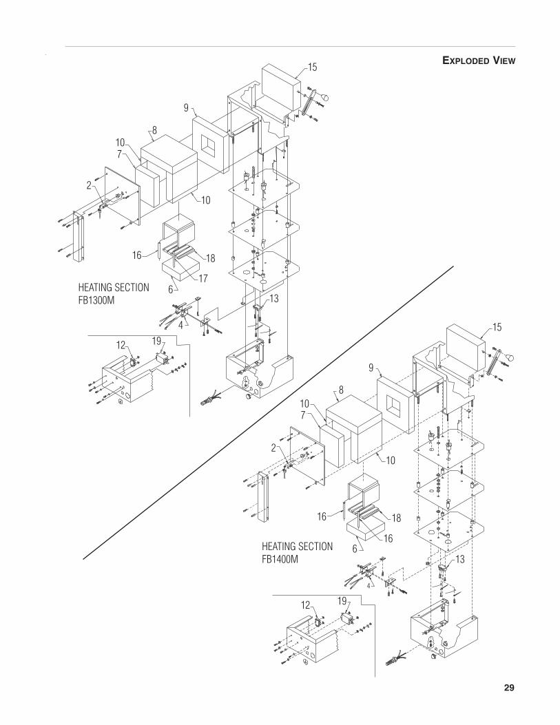
EXPLODED VIEW
29
30
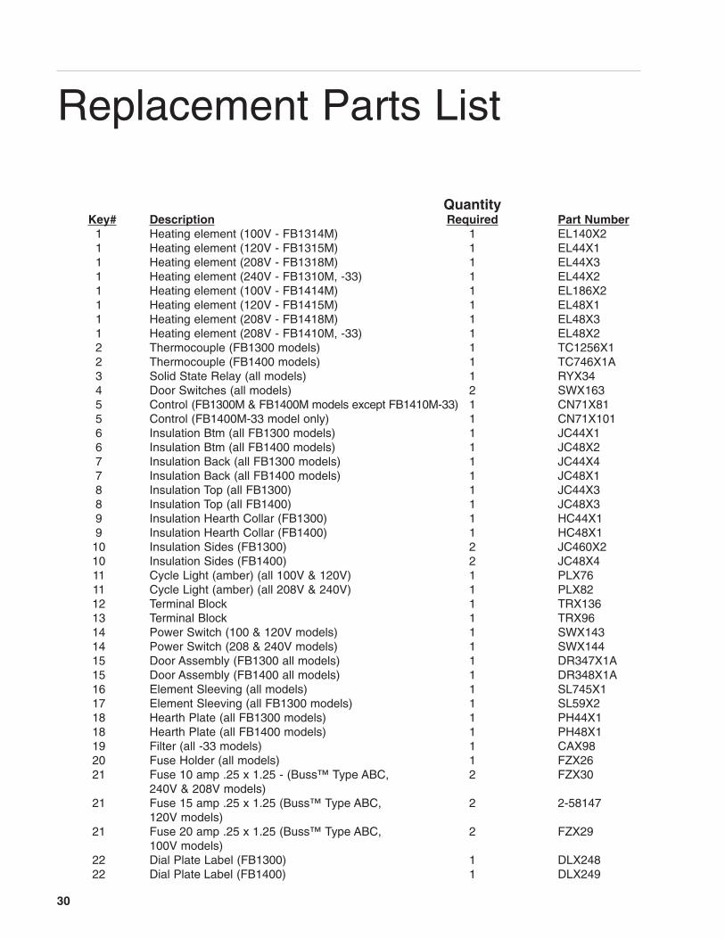
QuantityKey# Description Required Part Number
1 Heating element (100V - FB1314M) 1 EL140X21 Heating element (120V - FB1315M) 1 EL44X11 Heating element (208V - FB1318M) 1 EL44X31 Heating element (240V - FB1310M, -33) 1 EL44X21 Heating element (100V - FB1414M) 1 EL186X21 Heating element (120V - FB1415M) 1 EL48X11 Heating element (208V - FB1418M) 1 EL48X31 Heating element (208V - FB1410M, -33) 1 EL48X22 Thermocouple (FB1300 models) 1 TC1256X12 Thermocouple (FB1400 models) 1 TC746X1A3 Solid State Relay (all models) 1 RYX344 Door Switches (all models) 2 SWX1635 Control (FB1300M & FB1400M models except FB1410M-33) 1 CN71X815 Control (FB1400M-33 model only) 1 CN71X1016 Insulation Btm (all FB1300 models) 1 JC44X16 Insulation Btm (all FB1400 models) 1 JC48X27 Insulation Back (all FB1300 models) 1 JC44X47 Insulation Back (all FB1400 models) 1 JC48X18 Insulation Top (all FB1300) 1 JC44X38 Insulation Top (all FB1400) 1 JC48X39 Insulation Hearth Collar (FB1300) 1 HC44X19 Insulation Hearth Collar (FB1400) 1 HC48X110 Insulation Sides (FB1300) 2 JC460X210 Insulation Sides (FB1400) 2 JC48X411 Cycle Light (amber) (all 100V & 120V) 1 PLX7611 Cycle Light (amber) (all 208V & 240V) 1 PLX8212 Terminal Block 1 TRX13613 Terminal Block 1 TRX9614 Power Switch (100 & 120V models) 1 SWX14314 Power Switch (208 & 240V models) 1 SWX14415 Door Assembly (FB1300 all models) 1 DR347X1A15 Door Assembly (FB1400 all models) 1 DR348X1A16 Element Sleeving (all models) 1 SL745X117 Element Sleeving (all FB1300 models) 1 SL59X218 Hearth Plate (all FB1300 models) 1 PH44X118 Hearth Plate (all FB1400 models) 1 PH48X119 Filter (all -33 models) 1 CAX9820 Fuse Holder (all models) 1 FZX2621 Fuse 10 amp .25 x 1.25 - (Buss™ Type ABC, 2 FZX30
240V & 208V models)21 Fuse 15 amp .25 x 1.25 (Buss™ Type ABC, 2 2-58147
120V models)21 Fuse 20 amp .25 x 1.25 (Buss™ Type ABC, 2 FZX29
100V models)22 Dial Plate Label (FB1300) 1 DLX24822 Dial Plate Label (FB1400) 1 DLX249
Replacement Parts List
31
Ordering Procedures
Please refer to the Specification Plate for the complete model number, serial number, andseries number when requesting service, replacement parts or in any correspondence con-cerning this unit.All parts listed herein may be ordered from the Barnstead International dealer from whomyou purchased this unit or can be obtained promptly from the factory. When service orreplacement parts are needed we ask that you check first with your dealer. If the dealercannot handle your request, then contact our Customer Service Department at 563-556-2241 or 800-553-0039.Prior to returning any materials to Barnstead International, please contact our CustomerService Department for a “Return Goods Authorization” number (RGA). Material returnedwithout a RGA number will be refused.
32
One Year Limited WarrantyBARNSTEAD INTERNATIONAL (“BARNSTEAD”) warrants that if a product manufactured by Barnstead shallbe free of defects in materials and workmanship for one (1) year from the first to occur of (i) the date the prod-uct is sold by BARNSTEAD or (ii) the date the product is purchased by the original retail customer (the“Commencement Date”). Except as expressly stated above, BARNSTEAD MAKES NO OTHER WARRANTY,EXPRESSED OR IMPLIED, WITH RESPECT TO THE PRODUCTS AND EXPRESSLY DISCLAIMS ANY ANDALL WARRANTIES, INCLUDING BUT NOT LIMITED TO, WARRANTIES OF DESIGN, MERCHANT ABILITYAND FITNESS FOR A PARTICULAR PURPOSE.
An authorized representative of BARNSTEAD must perform all warranty inspections. In the event of a defectcovered by BARNSTEAD’s warranty, BARNSTEAD shall, as its sole obligation and exclusive remedy, providefree replacement parts to remedy the defective product. In addition, for products sold by BARNSTEAD withinthe continental United States or Canada, BARNSTEAD shall provide provide free labor to repair the productswith the replacement parts, but only for a period of ninety (90) days from the Commencement Date.
BARNSTEAD’s warranty provided hereunder shall be null and void and without further force or effect if thereis any (i) repair made to the product by a party other than BARNSTEAD or its duly authorized service repre-sentative, (ii) misuse (including use inconsistent with written operating instructions for the product), mishan-dling, contamination, overheating, modification or alteration of the product by any customer or third party or(iii) use of replacement parts that are obtained from a party who is not an authorized dealer of BARNSTEAD.
Heating elements, because of their susceptibility to overheating and contamination, must be returned to theBARNSTEAD factory and if, upon inspection, it is concluded that failure is due to factors other than excessivehigh temperature or contamination, BARNSTEAD will provide warranty replacement. As a condition to thereturn of any product, or any constituent part thereof, to BARNSTEAD’s factory, it shall be sent prepaid and aprior written authorization from BARNSTEAD assigning a Return Goods Number to the product or part shallbe obtained.
IN NO EVENT SHALL BARNSTEAD BE LIABLE TO ANY PARTY FOR ANY DIRECT, INDIRECT, SPECIAL,INCIDENTAL, OR CONSEQUENTIAL DAMAGES, OR FOR ANY DAMAGES RESULTING FROM LOSS OFUSE OR PROFITS, ANTICIPATED OR OTHERWISE, ARISING OUT OF OR IN CONNECTION WITH THESALE, USE OR PERFORMANCE OF ANY PRODUCTS, WHETHER SUCH CLAIM IS BASED ON CON-TRACT, TORT (INCLUDING NEGLIGENCE), ANY THEORY OF STRICT LIABILITY OR REGULATORYACTION.
The name of the authorized Barnstead International dealer nearest you may be obtained by calling 1-800-446-6060 (563-556-2241) or writing to:
2555 Kerper BoulevardP.O. Box 797Dubuque, Iowa 52001-0797Phone: 563-556-2241 or 800-553-0039Fax: 563-589-0516E-mail: [email protected]