Embed Size (px)
Citation preview
Addendum to
ABB41-164H
Instruction Leaflet
Effective: August 1990
All possible contingencies which may arise during insvariations of this equipment do not purport to be covereby purchaser regarding this particular installation, opeInc. representative should be contacted.
Printed in U.S.A.
A - Add New Information � C - Change Ex
Page 5 _______________________
SETTINGS:
Delete the third paragraph beginning
Delete the fourth paragraph bearing
Page 5 _______________________
SETTINGS:
Add the following:
C
Since the tap block screw carriesare turned tight.
In order to avoid opening currentunder load, the relay must be firsshorting switches on the case will shThe taps should then be changed wserted into the case.
D
A
Type KRQ Directional Overcurrent Negative Sequence Ground Relay
tallation, operation or maintenance, and all details andd by these instructions. If further information is desired
ration or maintenance of this equipment, the local ABB
isting Information � D - Delete Information
___________________________________
“CAUTION”
“In order to avoid opening . . . “
___________________________________
AUTION
operating current, be sure that the screws
transformer circuits when changing tapst removed from the case. Chassis operatingort the secondary of the current transformer.
ith the relay outside of the case and then rein-

41-164H Type KRQ Directional Overcurrent Negataive Sequence Relay
0
THIS PAGE RESERVED FOR NOTES

Instruction Leaflet
ABB 41-164H
Type KRQ Directional Overcurrent Negative Sequence Ground Relay
CAUTION!Before putting the relay into service, removeblocking from all the moving parts. Inspect therelay and operate all elements by hand to be sureno damage has occurred during shipment. Alsosee caution note under “SETTINGS”.
1.0 APPLICATION
The type KRQ relay is a high-speed directional over-current ground relay in which the directional unitoperates on negative sequence current and voltage,and the overcurrent unit operates on residual current.The negative sequence current and voltage areobtained by means of self-contained negative currentand voltage filters.
The relay is intended for use at locations where thepresent equipment or system conditions do not per-mit the use of the conventional types of directionalground relays operating entirely on residual currentand voltage.
At undergrounded substation on grounded systemswhere only two potential transformers are available,or where there is a delta-wye transformer betweenthe potential transformers and the protected line, thetype KRQ relay is applicable for ground protection.
The KRQ is also used, without modification to providedirectional ground fault protection in the KD carrierrelaying scheme. Operation of the relays in connec-tion with the carrier scheme is fully described in I. L.41-911.
2.0 CONSTRUCTION AND OPERATION
The type KRQ relay consists of a directional cylinderunit operating on negative sequence quantities, neg-ative sequence current and voltage filters, high-speedovercurrent cylinder unit operating on residual cur-rent, and an indicating contractor switch.
2.1 DIRECTIONAL UNIT (D)
The directional unit is a product induction cylindertype unit operating on the interaction between thepolarizing circuit flux and the operating circuit flux.
Mechanically, the directional unit is composed of fourbasic components: A die-cast aluminum frame, anelectromagnet, a moving element assembly, and amolded bridge.
The frame serves as the mounting structure for themagnetic core. The magnetic core which houses thelower pin bearing is secured to the frame by a lockingnut. The bearing can be replaced, if necessary, with-out having to remove the magnetic core from theframe.
The electromagnet has two series-connected polariz-ing coils mounted diametrically opposite one another;two series connected operating coils mounted dia-metrically opposite one another; two magnetic adjust-ing plugs; upper and lower adjusting plug clips, andtwo locating pins. The locating pins are used to accu-rately position the lower pin bearing, which isthreaded into the bridge. The electromagnet issecured to the frame by four mounting screws.
Effective: May 1985
Supersedes I.L. 41-164G Dated April 1977
Denotes Change Since Previous Issue*
All possible contingencies which may arise during installation, operation or maintenance, and alldetails and variations of this equipment do not purport to be covered by these instructions. If furtherinformation is desired by purchaser regarding this particular installation, operation or maintenanceof this equipment, the local ABB Inc. representative should be contacted.
Printed in U.S.A.

41-164H Type KRQ Directional Overcurrent Negataive Sequence Relay
2
Fig
.1T
ype
KR
Q R
elay
with
out c
ase
(Rea
r V
iew
).F
ig.2
Typ
e K
RQ
Rel
ay w
ithou
t cas
e (F
ront
Vie
w).

Type KRQ Directional Overcurrent Negataive Sequence Relay 41-164H
The moving element assembly consists of a spiralspring, contact carrying member, and an aluminumcylinder assembled to a molded hub which holds theshaft. The shaft has removable top and bottom jewelbearings. The shaft rides between the bottom pinbearing and the upper pin bearing with the cylinderrotating in an air gap formed by the electromagnetand the magnetic core.
The bridge is secured to the electromagnet andframe by two mounting screws. In addition to holdingthe upper pin bearing, the bridge is used for mount-ing the adjustable stationary contact housing. Thestationary contact housing is held in position by aspring type clamp. The spring adjuster is located onthe underside of the bridge and is attached to themoving contact arm by a spiral spring. The springadjuster is also held in place by a spring type clamp.
With the contacts closed, the electrical connection ismade through the stationary contact housing clamp,to the moving contact, through the spiral spring out tothe spring adjuster clamp.
2.2 NEGATIVE SEQUENCE FILTER
The current and voltage filters consist of reactors andresistors connected together as shown in the internalschematic (Fig. 3).
2.3 OVERCURRENT UNIT (I)
The overcurrent unit is similar in construction to thedirectional unit. The time phase relationship of thetwo air-gap fluxes necessary for the development oftorque is achieved by means of a capacitor con-nected in series with one pair of pole windings.
The normally-closed contact of the directional unit isconnected across one pair of pole windings of theovercurrent unit as shown in the internal schematics.This arrangement short-circuits the operating currentaround the pole windings, preventing the overcurrentunit from developing torque. If the directional unitshould pickup for a fault, this short-circuit is removedallowing the overcurrent contact to commence clos-ing almost simultaneously with the directional contactfor high-speed operation.
2.4 OVERCURRENT UNIT TRANSFORMER
This transformer is of the saturating type for limitingthe energy to the overcurrent unit at higher values offault current and to reduce C.T. burden. The primary
winding is tapped and these taps are brought out to atap block for ease in changing the pickup of the over-current unit. The use of a tapped transformer pro-vides approximately the same energy level at a givenmultiple of pickup current for any tap setting, result-ing in one time curve throughout the range of therelay.
Across the secondary is connected a non-linearresistor known as a varistor. The effect of the varistoris to reduce the voltage peaks applied to the overcur-rent unit and phase shifting capacitor.
2.5 INDICATING CONTACTOR SWITCH UNIT (ICS)
The indicating contactor switch is a small d-c oper-ated clapper type device. a magnetic armature, towhich leaf-spring mounted contacts are attached, isattracted to the magnetic core upon energization ofthe switch. When the switch closes, the moving con-tacts bridge two stationary contacts, completing thetrip circuit. Also during this operation two fingers onthe armature deflect a spring located on the front ofthe switch, which allows the operation indicator tar-get to drop. The target is reset from the outside of thecase by a push rod located at the bottom of thecover.
Figure 3: Internal Schematic of the Type KRQ Relay in
the Type FT42-case.
184A546
3

41-164H Type KRQ Directional Overcurrent Negataive Sequence Relay
Fig. 4. Time Curves of the Directional Unit (D). Fig. 5. Sensitivity Curve of the Directional Unit (D).
184A995 184A996
The front spring, in addition to holding the target, pro-vides restraint for the armature and thus controls thepickup value of the switch.
3.0 CHARACTERISTICS
3.1 INSTANTANEOUS OVERCURRENT UNIT (I)
The relays are available in the following currentranges:
The tap value is the minimum current required to justclose the overcurrent relay contacts. For pickup set-
tings in between taps, refer to the section underAdjustments.
3.2 DIRECTIONAL UNIT (D)
The directional unit minimum pickup is approximately0.76 volt-amperes (e.g. 0.19 volt and 4 amperes) interms of negative sequence quantities applied at therelay terminals at the maximum torque angle ofapproximately 98° (current leading voltage). See Fig.5.
3.3 TRIP CIRCUIT
The main contacts will safely close 30 amperes at250 volts d-c and the seal-in contacts of the indicat-ing contactor switch will safely carry this current longenough to trip a circuit breaker.
The indicating contactor switch has a pickup ofapproximately 1 ampere.
The trip circuit resistance is 0.1 ohm dc.
Range Taps
0.5-2 Amps 0.5 0.75 1.0 1.25 1.5 2
1-4 1.0 1.5 2.0 2.5 3.0 4.0
2-8 2 3 4 5 6 8
4-16 4 6 8 9 12 16
10-40 10 15 20 24 30 40
4

Type KRQ Directional Overcurrent Negataive Sequence Relay 41-164H
*
4.0 SETTINGS
4.1 OVERCURRENT UNIT (I)
The only setting required is the pickup current settingwhich is made by means of the connector screwlocated on the tap plate. By placing the connectorscrew in the desired tap, the relay will just close itscontacts at the tap value current.
For carrier relaying, the carrier-trip overcurrent unitlocated in the type KRQ relay should be set on ahigher tap than the carrier-stat overcurrent unitlocated at the opposite end of the line.
CAUTION: Since the tap block connector screwcarries operating current, be sure that the screwis turned tight.
In order to avoid opening the current transformer cir-cuits when changing taps under load, connect aspare tap screw in the desired tap position beforeremoving the other tap screw from the original tapposition.
4.2 DIRECTIONAL UNIT (D)
No setting is required.
5.0 INSTALLATION
The relays should be mounted on switchboard pan-els or their equivalent in a location free from dirt,moisture, excessive vibration and heat. Mount therelay vertically by means of the two mounting studsfor the type FT projection case or by means of thefour mounting holes on the flange for the semi-flushtype FT case. Either of the studs or the mountingscrews may be utilized for grounding the relay. Theelectrical connections may be made directly to theterminals by means of screws for steel panel mount-ing or to terminal studs furnished with the relay forthick panel mounting. The terminal studs may beeasily removed or inserted by locking two nuts on thestuds and then turning the proper nut with a wrench.
For detailed FT case information, refer to I.L. 41-076.
The external connections of the directional overcur-rent relay are shown in Fig. 6.
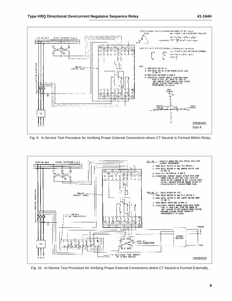
External connections may be checked by using therelay as specified in either Fig. 9 or 10 dependingupon whether or not the 15/5A auxiliary CT is used.
About 0.3 of an ampere load current at a knownpower-factor angle should be flowing in the main CTsecondaries. This check is appropriate prior to com-missioning the relay or when troubleshooting.
6.0 ADJUSTMENTS AND MAINTENANCE
The proper adjustments to insure correct operation ofthis relay have been made at the factory. Uponreceipt of the relay, no customer adjustments, otherthan those covered under “SETTINGS”, should berequired.
6.1 CONTACTS
The moving contact assembly has been factoryadjusted for low contact bounce performance andshould not be changed.
The set screw in each stationary contact has beenadjusted for optimum follow and this adjustmentshould not be disturbed.
6.2 ACCEPTANCE CHECK
The following check is recommended to insure thatthe relay is in proper working order:
6.3 OVERCURRENT UNIT (I)
1. Contact Gap
The gap between the stationary and moving contactswith the relay in the de-energized position should beapproximately .020".
2. Minimum Trip Current
The normally-closed contact of the directional unitshould be blocked open when checking the pickup ofthe overcurrent unit.
The pickup of the overcurrent unit can be checked by
inserting the tap screw in the desired tap hole and applying
rated tap value current. The contact should close within
±5% of tap value current.
5
41-164H Type KRQ Directional Overcurrent Negataive Sequence Relay
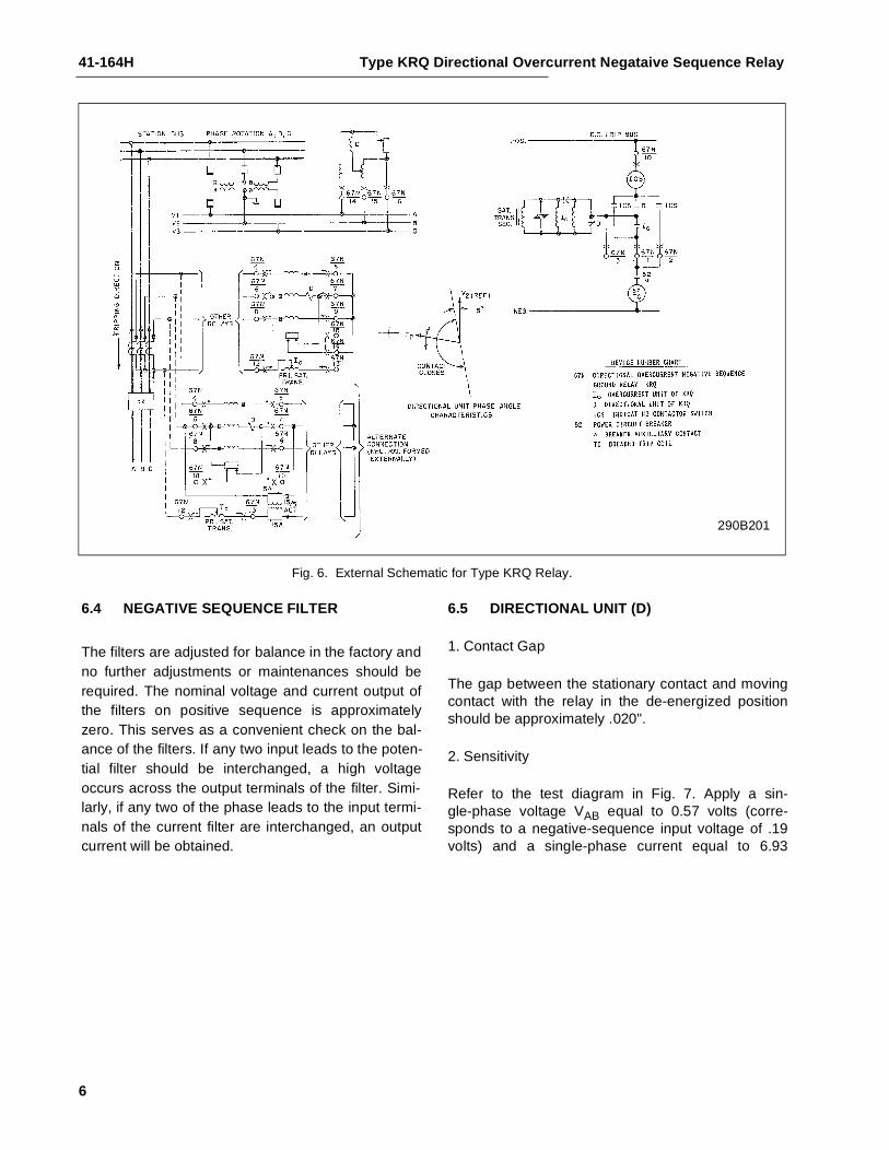
290B201
Fig. 6. External Schematic for Type KRQ Relay.
6.4 NEGATIVE SEQUENCE FILTER
The filters are adjusted for balance in the factory andno further adjustments or maintenances should berequired. The nominal voltage and current output ofthe filters on positive sequence is approximatelyzero. This serves as a convenient check on the bal-ance of the filters. If any two input leads to the poten-tial filter should be interchanged, a high voltageoccurs across the output terminals of the filter. Simi-larly, if any two of the phase leads to the input termi-nals of the current filter are interchanged, an outputcurrent will be obtained.
6.5 DIRECTIONAL UNIT (D)
1. Contact Gap
The gap between the stationary contact and movingcontact with the relay in the de-energized positionshould be approximately .020".
2. Sensitivity
Refer to the test diagram in Fig. 7. Apply a sin-gle-phase voltage VAB equal to 0.57 volts (corre-sponds to a negative-sequence input voltage of .19volts) and a single-phase current equal to 6.93
6

Type KRQ Directional Overcurrent Negataive Sequence Relay 41-164H
184A599Sub 5
Fig. 7. Test Diagram for Checking Maximum-Torque Angle and Minimum Voltage for
Contact Closure of Directional Unit.*
amperes as shown (corresponds to a negativesequence input current of 4 amperes). With a anglemeter connected as shown, rotate the phase shifteruntil the current leads the voltage by 188°.
This corresponds to the negative sequence compo-nent of current leading the negative sequence com-ponent of voltage by 98°. The directional unit contactshould pickup within ±10% of the above input voltageto the relay. The above quantities are determined asfollows:
for VAB = 0.57 volts
VA2 Neg. Sequence Voltage=
VA213--- VAN a
2VBN aVCN+ +
=
VA213--- 2
3---VAB
13---a
2VAB–
13---aVAB–
=
VA2
VAB3
----------- 23---
13---a
2–
13---a–
=
VA2
VAB3
-----------=
VA2 0.19 volts=
IA213--- IA a
2IB aIC+ +
=
IA213--- 0 a
2I aI–+( )=
7

41-164H Type KRQ Directional Overcurrent Negataive Sequence Relay
Sub 3290B264
Fig. 8. Test Diagram for Calibration of Negative Sequence Current Filter in KRQ Relay.
for I = 6.93 amps.
3. Spurious Torque
With the relay connected in the test diagram asabove, remove the input voltage and connect termi-nals 14, 15, and 16 together. Remove thephase-angle meter. With 80 amperes single-phasecurrent applied, there should be no spurious closingtorque.
4. Core Adjustment
a. Apply 40 volts balanced 3-phase voltage, 60 Hz.to terminals 14, 15 and 16 of the relay. Do notapply current. No trip should be observed for thiscondition. Reverse the voltage to terminals 14and 15. No trip should be observed
b. If trip is observed for either condition in “a” pro-ceed as follows: With balanced 40 V. 3-phase 60Hz voltage applied to terminals 14, 15 and 16
adjust core until the contact arm just restrains.The core can be adjusted by the use of an insu-lated screwdriver in the slots at the bottom of thecylinder unit. Recheck on balanced 3-phas. 40 Vpositive sequence voltage. Relay must not oper-ate.
5. Refer to Fig. 8.
Do not apply voltage. Pass 5 Amps. in terminal 6 andout terminal 8. There should be no trip. Reverse thecurrent: no trip.
6.6 INDICATING CONTACTOR SWITCH (ICS)
Close the main relay contacts and pass sufficient d-ccurrent through the trip circuit to close the contacts ofthe ICS. This value of current should be between 1and 1.2 amperes. The indicator target should dropfreely.
The contact gap should be approximately 5/64”between the bridging moving contact and the adjust-able stationary contacts. The bridging moving con-tact should touch both stationary contactssimultaneously. The third moving contact shouldmake at approximately the same time.
IA2I
3------- 90°–∠=
IA2 4 90°amps.–∠=
*
8
Type KRQ Directional Overcurrent Negataive Sequence Relay 41-164H
9
290B560Sub 4
290B559
Fig. 9. In-Service Test Procedure for Verifying Proper External Connections where CT Neutral is Formed Within Relay.
Fig. 10. In-Service Test Procedure for Verifying Proper External Connections where CT Neutral is Formed Externally.

41-164H Type KRQ Directional Overcurrent Negataive Sequence Relay
7.0 ROUTINE MAINTENANCE
All relays should be inspected periodically and theoperation should be checked at least once everyyear or at such other time intervals as may be dic-tated by experience to be suitable to the particularapplication.
All contacts should be periodically cleaned. A contactburnisher S#182A836H01 is recommended for thispurpose. The use of abrasive material for cleaningcontacts is not recommended, because of the dangerof embedding small particles in the face of the softsilver and thus impairing the contact.
7.1 CALIBRATION
Use the following procedure for calibrating the relay ifthe relay has been taken apart for repairs or theadjustments have been disturbed. This procedureshould not be used unless it is apparent that the relayis not in proper working order. (See “AcceptanceCheck”).
7.2 OVERCURRENT UNIT (I)
1. The upper pin bearing should be screwed downuntil there is approximately .025" clearancebetween it and the top of shaft bearing. Theupper pin bearing should then be securely lockedin position with the lock nut. The lower bearingposition is fixed and cannot be adjusted.
2. The contact gap adjustment for the overcurrentunit is made with the moving contact in the resetposition, i.e. against the right side of the bridge.Move in the left-hand stationary contact until itjust touches the moving contact. Then back offthe stationary contact 2/3 of one turn for a gap ofapproximately .020". The clamp holding the sta-tionary contact housing need not be loosened forthe adjustment since the clamp utilizes aspring-type action in holding the stationary con-tact in position.
3. The sensitivity adjustment is made by varying thetension of the spiral spring attached to the mov-ing element assembly. The spring is adjusted byplacing a screwdriver or similar tool into one ofthe notches located on the periphery of thespring adjuster and rotating it. The springadjuster is located on the underside of the bridgeand is held in place by a spring type clamp thatdoes not have to be loosened prior to making thenecessary adjustments.
Before applying current, block open the normallyclosed contact of the directional unit. Insert the tapscrew in the minimum value tap setting and adjustthe spring such that the contacts will close as indi-cated by a neon lamp in the contact circuit whenenergized with the required current. The pickup ofthe overcurrent unit with the tap screw in any othertap should be within ±5% of tap value.
If adjustment of pickup current in between tap set-tings is desired, insert the tap screw in the next low-est tap setting and adjust the spring as described. Itshould be noted that this adjustment results in aslightly different time characteristic curve and bur-den.
7.3 NEGATIVE SEQUENCE VOLTAGE FILTER
A. Apply 120 volts balanced 3-phase voltage 60cycles to terminals 14, 15, and 16 of the relay,making sure that phase 1, 2 and 3 of the appliedvoltage is connected to terminals 14, 15, and 16respectively.
B. Using a calibrated high resistance rectox voltme-ter, measure the voltage between the tap on theauto-transformer (middle terminal, lower righthand reactor, front view) and the tap on theadjustable 2" resistor. If the voltage is high (40 to50 volts) the filter is probably improperly con-nected. If properly connected, the voltage will below. Using a low range (approximately 5 volts)move the adjustable tap until the voltage reads aminimum. This value should be less than 1.5volts.
7.4 NEGATIVE SEQUENCE CURRENT FILTER
Refer to Fig. 8 for positive sequence calibration.
A. Connect relay terminals 7 and 9 together.Remove lead to lower right hand terminal ofmutual reactor (right side view) to disconnect thedirectional unit.
B. Pass 10 amperes in terminal 6 and out terminal8.
C With a 0-15 volts, rectox type voltmeter, measureand record voltage between terminals 6 and thelower right hand terminal of mutual reactor. Thisvoltage should be between 1.85 and 1.95 volts.
10

Type KRQ Directional Overcurrent Negataive Sequence Relay 41-164H
D. Now measure the voltage from terminal 6 to ter-minal 7. Adjust the top filter resistor tap until thisvoltage is 1.73 times the reading of 4. part C.
Refer to Fig. 8 for neutral tap calibration.
Using the test connections as shown and a low rangevoltmeter connected between terminal 6 and 7,adjust the middle filter resistor tap connection untilthe measured voltage is zero. Reconnect lead tomutual reactor at end of this test.
7.5 DIRECTIONAL. UNIT (D)
1. The upper bearing screw should be screweddown until there is approximately .025" clearancebetween it and the top of the shaft bearing. Theupper pin bearing should then be securely lockedin position with the lock nut.
2. Contact gap adjustment for the directional unit ismade with the moving contact in the reset posi-tion, i.e., against the right side of the bridge.Advance the right hand stationary contact untilthe contacts just close. Then advance the sta-tionary contact an additional one-quarter turn.
Now move in the left-hand stationary contactuntil it just touches the moving contact. Thenback off the stationary contact 3/4 of one turn fora contact gap of .020" to .024". The clamp hold-ing the stationary contact housing need not beloosened for the adjustment since the clamp uti-lizes a spring-type action in holding the station-ary contact in position.
3. The sensitivity adjustment is made by varying thetension of the spiral spring attached to the mov-ing element assembly. The spring is adjusted byplacing a screwdriver or similar tool into one ofthe notches located on the periphery of thespring adjuster and rotating it. The springadjuster is located on the underside of the bridgeand is held in place by a spring type clamp thatdoes not have to be loosened prior to making thenecessary adjustments.
The spring is to be adjusted such that the con-tacts will close when the relay is energized with0.57 volts and 6.93 amps at 188° (current lead-ing voltage), considering the relay connected tothe test circuit in Fig. 7.
4. The magnetic plugs ire used to reverse anyunwanted spurious torques that may be presentwhen the relay is energized on current alone.
The reversing of the spurious torques is accom-plished by using the adjusting plugs in the fol-lowing manner:
a) Connect the relay voltage circuit terminals (phase1, 2, and 3) together.
b) Apply 80 amperes single-phase current (momen-tarily) in phase 2 terminal and out phase 3 termi-nal.
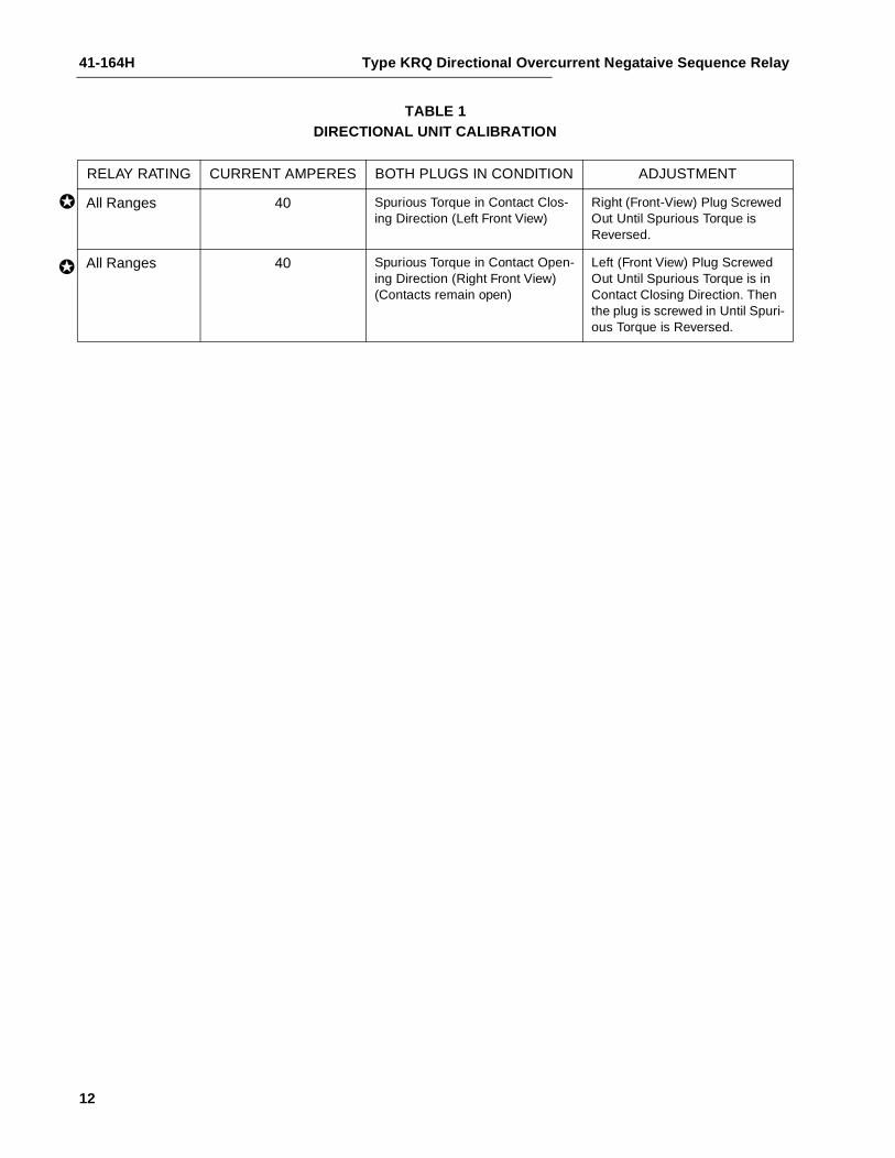
Plug adjustment is then made per Table I such thatany contact closing spurious torques are reversed.The plugs are held in position by upper and lowerplug clips. These clips need not be disturbed in anymanner when making the necessary adjustments.
The magnetic plug adjustment may be utilized topositively close the contacts on current alone. Thismay be desired on some installations in order to ,insure that the relay will always trip the breaker onzero potential.
7.6 INDICATING CONTACTOR SWITCH (ICS)
First adjust the two main contacts (left and right handside, front view), for a contact gap of 5/64” (-1/64”,+0).
Close the main relay contacts and check to see thatthe relay picks up between 1 and 1.2 amperes d-c.
Make sure that all three contacts make and the targetdrops freely when the above current is applied.
8.0 RENEWAL PARTS
Repair work can be done most satisfactorily at thefactory. However, interchangeable parts can be fur-nished to the customers who are equipped for doingrepair work. When ordering parts, always give thecomplete nameplate data.
11
41-164H Type KRQ Directional Overcurrent Negataive Sequence Relay
12
TABLE 1DIRECTIONAL UNIT CALIBRATION
RELAY RATING CURRENT AMPERES BOTH PLUGS IN CONDITION ADJUSTMENT
All Ranges 40 Spurious Torque in Contact Clos-ing Direction (Left Front View)
Right (Front-View) Plug Screwed Out Until Spurious Torque is Reversed.
All Ranges 40 Spurious Torque in Contact Open-ing Direction (Right Front View) (Contacts remain open)
Left (Front View) Plug Screwed Out Until Spurious Torque is in Contact Closing Direction. Then the plug is screwed in Until Spuri-ous Torque is Reversed.
✪
✪

Type KRQ Directional Overcurrent Negataive Sequence Relay 41-164H
13
ENERGY REQUIREMENTS
INSTANTANEOUS OVERCURRENT UNIT OPERATING CURRENT CIRCUIT - 60 HERTZ
AMPERE RANGE TAP VA AT TAP VALUE P.F. ANGLE VA AT 5 AMPS. P.F. ANGLE
.5- 2
.5
.7511.251.52
.37
.38
.39
.41
.43
.45
393635343230
2413
8.56.04.62.9
463734323128
1-4
11.522.534
.41
.44
.47
.50
.53
.59
363230282624
9.05.03.02.11.50.93
363229272624
2 8
234568
1.11.21.31.41.51.8
494338353329
6.53.32.11.41.10.7
484237353329
4-16
4689
1216
1.51.71.81.92.22.5
514540383430
2.41.20. 70.60.370.24
514540383431
10-40
101520243040
1.72.43.13.64.24.9
282116151211
0.430.270.200.150.110.08
282117151312

41-164H Type KRQ Directional Overcurrent Negataive Sequence Relay
14
ENERGY REQUIREMENTS
FOR THE DIRECTIONAL UNIT AND THE FILTER
(All Burdens at 60 Hertz)
The current burden of the relay with positive sequence current applied (no output current to the directional unit) is as follows:
Phase Continuous One Second Watts Volt-Amps.Rating-Amps. Rating-Amps. at 5 Amps. at 5 Amps. Power Factor Angle
1 10 150 5.4 7.5 44° Lag2 10 150 5.5 5.5 0°3 10 150 .35 1.28 74° Lag
The current burden of the relay with zero sequence currents applied is as follows:
Watts Volt - Amps.Phase At 5 Amps. At 5 Amps. Power Factor Angle
1 4.66 5.5 32°2 4.92 5.0 10°3 3.30 3.7 27°
The voltage burden of the relay with positive sequence voltage applied (no output voltage to the directional unit) is as follows:
Pot. Transf. Across Phase Volts Watts Volt-Amps. Power Factor Angle
Burden values on three star connected potential transformers. Values at the star voltage of 66.4 volts (115 volts delta).
1 115 0 26.8 90° Lag2 115 0.2 0.3 48° Lag3 115 23.2 27.0 30° Lag
Burden values on two open-delta potential transformers. Values at 115 volts.
12 115 -23.2 46.5 120° Lag23 115 46.6 46.6 0°23 115 .10 .48 58° Lag31 115 23.2 46.5 60° Lag31 115 23.2 46.6 60° Lag12 115 0.50 0.52 2° Lead
Burden values on three delta connected potential transformers. Values at 115 volts.
31 115 15.4 31.0 60° Lag12 115 -7.8 15.6 120° Lag23 115 15.6 15.6 0°


41-164H Type KRQ Directional Overcurrent Negataive Sequence Relay
16
THIS PAGE RESERVED FOR NOTES

Type KRQ Directional Overcurrent Negataive Sequence Relay 41-164H
17
THIS PAGE RESERVED FOR NOTES

ABB Inc.4300 Coral Ridge DriveCoral Springs, Florida 33065Telephone: +1 954-752-6700Fax: +1 954-345-5329www.abb.com/substation automation
IL 4
1-16
4 - R
evis
ion
H
ABB