Embed Size (px)
Citation preview
Twin DVB-S/S2 & DVB-T/T2/C - DVB-C transmodulatorstdq420C, ttq420C, tdq420, ttq420
1. Product descriptionThe devices are transmodulators with two DVB-S/S2 (tdq420C, tdq420), DVB-T/T2/C (ttq420C, ttq420) input channels
and two DVB-C output channels. The devices are designed for digital transmodulation with Transport Stream Processing of TV or Radio programmes issued from FTA (Free to air) or encrypted digital reception; in case of encrypted signal, the CAM (Conditional access module) containing the operator's smart card must fitted in the slot. Modules processor enables, services filtering, modifying SI (Service Information), generating NIT (Network Information table), LCN (Local Channel Number), restamping PCR (Program Clock Reference). All of the configurations can be changed by using the Web Interface.
tdq420C – transmodulator with two DVB-S/S2 input channels and two DVB-C output channels with two CAMs.ttq420C – transmodulator with two DVB-T/T2/C input channels and two DVB-C output channels with two CAMs.tdq420 – transmodulator with two DVB-S/S2 input channels and two DVB-C output channels.ttq420 – transmodulator with two DVB-T/T2/C input channels and two DVB-C output channels.
Transmodulators can be used as stand alone devices.The product is intended for indoor usage only.
2. Safety instructionsInstallation of the transmodulator must be done according IEC60728-11 and national safety standards. Any repairs must be made by qualified personnel. Do not expose this transmodulator to moisture or splashing water and make sure no objects filled with liquids, such as
vases, are placed near or on the unit. Avoid placing the transmodulator next to heat sources such as central heating components or in areas of high humidity. Keep the transmodulator away from naked flames. If the transmodulator has been kept in cold conditions for a long time, bringing it into a warm environment may cause
condensation, so allow it to warm up for no less than 2 hours before plugging into the mains. Ventilation should not be impeded by covering the transmodulator, such as newspapers, table-cloths, curtains etc. Mount the transmodulator in a vertical position only. If installing in a 19” rack system additional forced air cooling fans may
be required (see table "Technical specifications" - operating temperature range). Always allow 10 cm of free space from the top, front and bottom of the unit to enable any heat to be dissipated.
Draugystes str. 22, LT-51256 Kaunas, Lithuania, tel.: +370 37 - 31 34 44, fax: +370 37 - 31 35 55 E-mail: [email protected], http://www.terraelectronics.com
Channel processing equipment
Vers. 1.07
This product complies with the relevant clauses of the European Directive 2002/96/EC. The unit must be recycled or discarded according to applicable local and national regulations.
Equipment intended for indoor usage only.
TERRA confirms, that this product is in accordance to following norms of EU: EMC norm EN50083-2, safety norm EN60065, RoHS norm EN50581.
TERRA confirms, that this product is in accordance with Custom Union Technical Regulations: “Electromagnetic compatibility of technical equipment“ CU TR 020/2011, “On safety of low-voltage equipment“ CU TR 004/2011.
TERRA confirms, that this product is in accordance with safety standard AS/NZS 60065 and EMC standards of Australia.
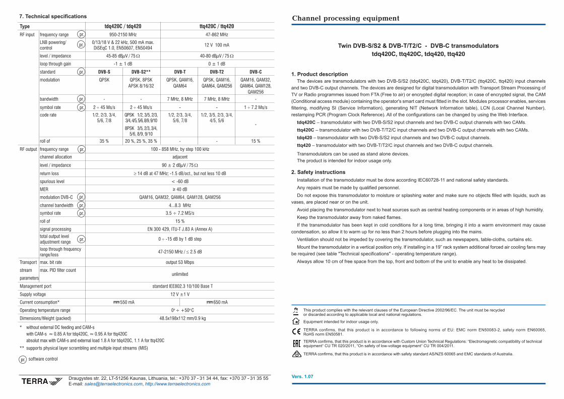
Type tdq420C / tdq420 ttq420C / ttq420
RF input frequency range 950-2150 MHz 47-862 MHz
LNB powering/ 0/13/18 V & 22 kHz, 500 mA max. 12 V 100 mA control DiSEqC 1.0, EN50607, EN50494
level / impedance 45-85 dBµV / 75 Ω 40-80 dBµV / 75 Ω
loop through gain -1 ± 1 dB 0 ± 1 dB
standard DVB-S DVB-S2** DVB-T DVB-T2 DVB-C
modulation QPSK QPSK, 8PSK QPSK, QAM16, QPSK, QAM16, QAM16, QAM32, APSK 8/16/32 QAM64 QAM64, QAM256 QAM64, QAM128, QAM256
bandwidth - - 7 MHz, 8 MHz 7 MHz, 8 MHz -
symbol rate 2 ÷45 Ms/s 2 ÷45 Ms/s - - 1 ÷7.2 Ms/s
code rate 1/2, 2/3, 3/4, QPSK 1/2, 3/5, 2/3, 1/2, 2/3, 3/4, 1/2, 3/5, 2/3, 3/4,
-
5/6, 7/8 3/4, 4/5, 5/6, 8/9, 9/10 5/6, 7/8 4/5, 5/6
8PSK 3/5, 2/3, 3/4, 5/6, 8/9, 9/10
roll of 35 % 20 %, 25 %, 35 % - - 15 %
RF output frequency range 100 - 858 MHz, by step 100 kHz
channel allocation adjacent
level / impedance 90 ± 2 dBµV / 75 Ω
return loss ≥ 14 dB at 47 MHz; -1.5 dB/oct., but not less 10 dB
spurious level < -60 dB
MER ≥ 40 dB
modulation DVB-C QAM16, QAM32, QAM64, QAM128, QAM256
channel bandwidth 4...8.3 MHz
symbol rate 3.5 ÷ 7.2 MS/s
roll of 15 %
signal processing EN 300 429, ITU-T J.83 A (Annex A)
total output level 0 ÷-15 dB by 1 dB step adjustment range
loop through frequency 47-2150 MHz / ≤2.5 dB range/loss
Transport max. bit rate output 53 Mbps
stream max. PID filter count unlimited
parameters
Management port standard IEE802.3 10/100 Base T
Supply voltage 12 V ±1 V
Current consumption* 550 mA 650 mA
Operating temperature range 0o ÷ +50o C
Dimensions/Weight (packed) 48.5x198x112 mm/0.9 kg
7. Technical specifications
pr.
pr.
pr.
pr.
pr.
pr.
pr.
pr.
pr.
pr.
pr. software control
* without external DC feeding and CAM-s with CAM-s » 0.85 A for tdq420C, » 0.95 A for ttq420C absolut max with CAM-s and external load 1.8 A for tdq420C, 1.1 A for ttq420C
** supports physical layer scrambling and multiple input streams (MIS)
152
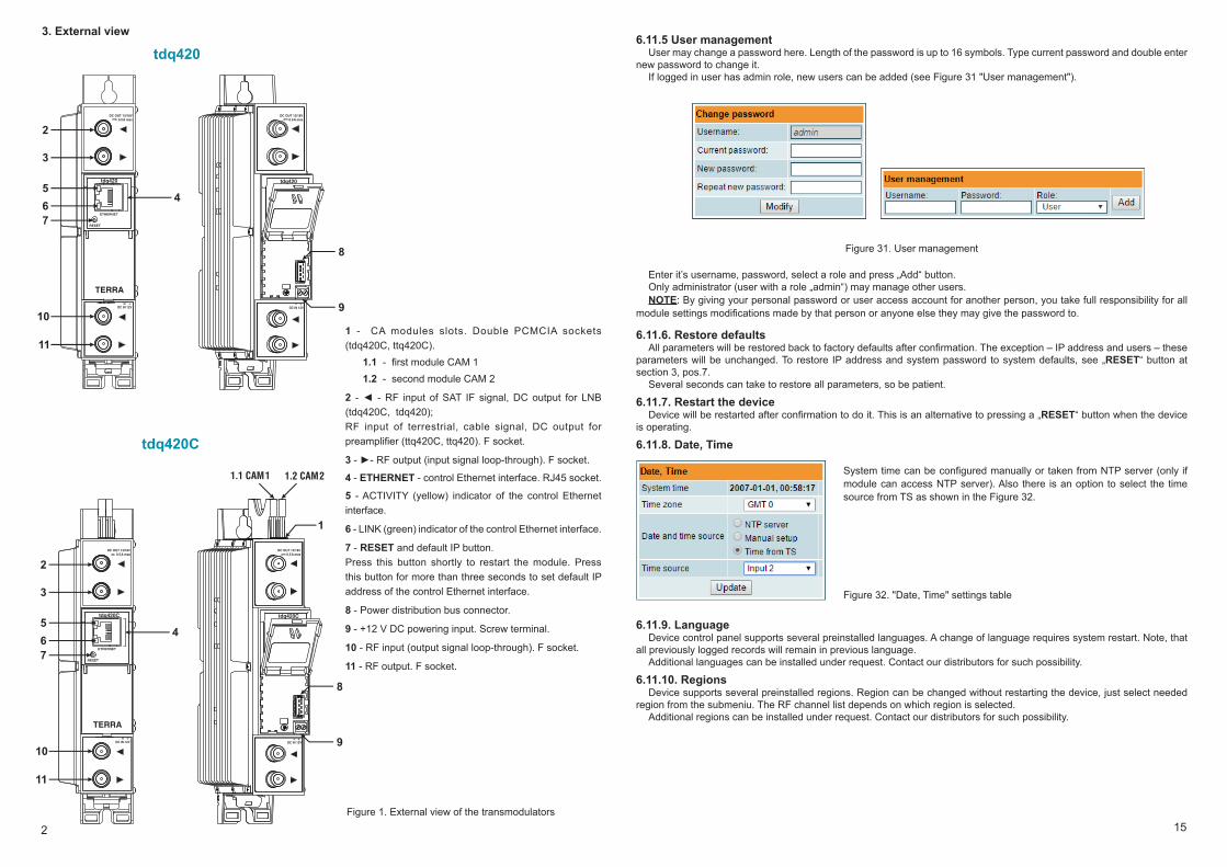
3. External view
tdq420
tdq420C
1 - CA modules slots. Double PCMCIA sockets (tdq420C, ttq420C). 1.1 - first module CAM 1 1.2 - second module CAM 2
2 - - RF input of SAT IF signal, DC output for LNB (tdq420C, tdq420); RF input of terrestrial, cable signal, DC output for preamplifier (ttq420C, ttq420). F socket.
3 - - RF output (input signal loop-through). F socket.
4 - ETHERNET - control Ethernet interface. RJ45 socket.
5 - ACTIVITY (yellow) indicator of the control Ethernet interface.
6 - LINK (green) indicator of the control Ethernet interface.
7 - RESET and default IP button. Press this button shortly to restart the module. Press this button for more than three seconds to set default IP address of the control Ethernet interface.
8 - Power distribution bus connector.
9 - +12 V DC powering input. Screw terminal.
10 - RF input (output signal loop-through). F socket.
11 - RF output. F socket.
Figure 1. External view of the transmodulators
DC IN 12V- +
tdq420
RESET
ETHERNET
TERRA
2
3
5
64
7
10
11
tdq420
DC IN 12V- +
8
9
DC OUT 13/18V0.5A max
DC OUT 13/18V0.5A max
DC IN 12V- +
tdq420C
RESET
ETHERNET
TERRA
2
3
5
64
7
10
11
tdq420C
DC IN 12V- +
8
9
1
1.1 CAM 1 1.2 CAM 2
DC OUT 13/18V0.5A max
DC OUT 13/18V0.5A max
6.11.5 User managementUser may change a password here. Length of the password is up to 16 symbols. Type current password and double enter
new password to change it. If logged in user has admin role, new users can be added (see Figure 31 "User management").
Figure 31. User management
Enter it’s username, password, select a role and press „Add“ button. Only administrator (user with a role „admin“) may manage other users.NOTE: By giving your personal password or user access account for another person, you take full responsibility for all
module settings modifications made by that person or anyone else they may give the password to.
6.11.6. Restore defaults All parameters will be restored back to factory defaults after confirmation. The exception – IP address and users – these
parameters will be unchanged. To restore IP address and system password to system defaults, see „RESET“ button at section 3, pos.7.
Several seconds can take to restore all parameters, so be patient.
6.11.7. Restart the deviceDevice will be restarted after confirmation to do it. This is an alternative to pressing a „RESET“ button when the device
is operating.
6.11.8. Date, Time
System time can be configured manually or taken from NTP server (only if module can access NTP server). Also there is an option to select the time source from TS as shown in the Figure 32.
Figure 32. "Date, Time" settings table
6.11.9. LanguageDevice control panel supports several preinstalled languages. A change of language requires system restart. Note, that
all previously logged records will remain in previous language. Additional languages can be installed under request. Contact our distributors for such possibility.
6.11.10. RegionsDevice supports several preinstalled regions. Region can be changed without restarting the device, just select needed
region from the submeniu. The RF channel list depends on which region is selected.Additional regions can be installed under request. Contact our distributors for such possibility.
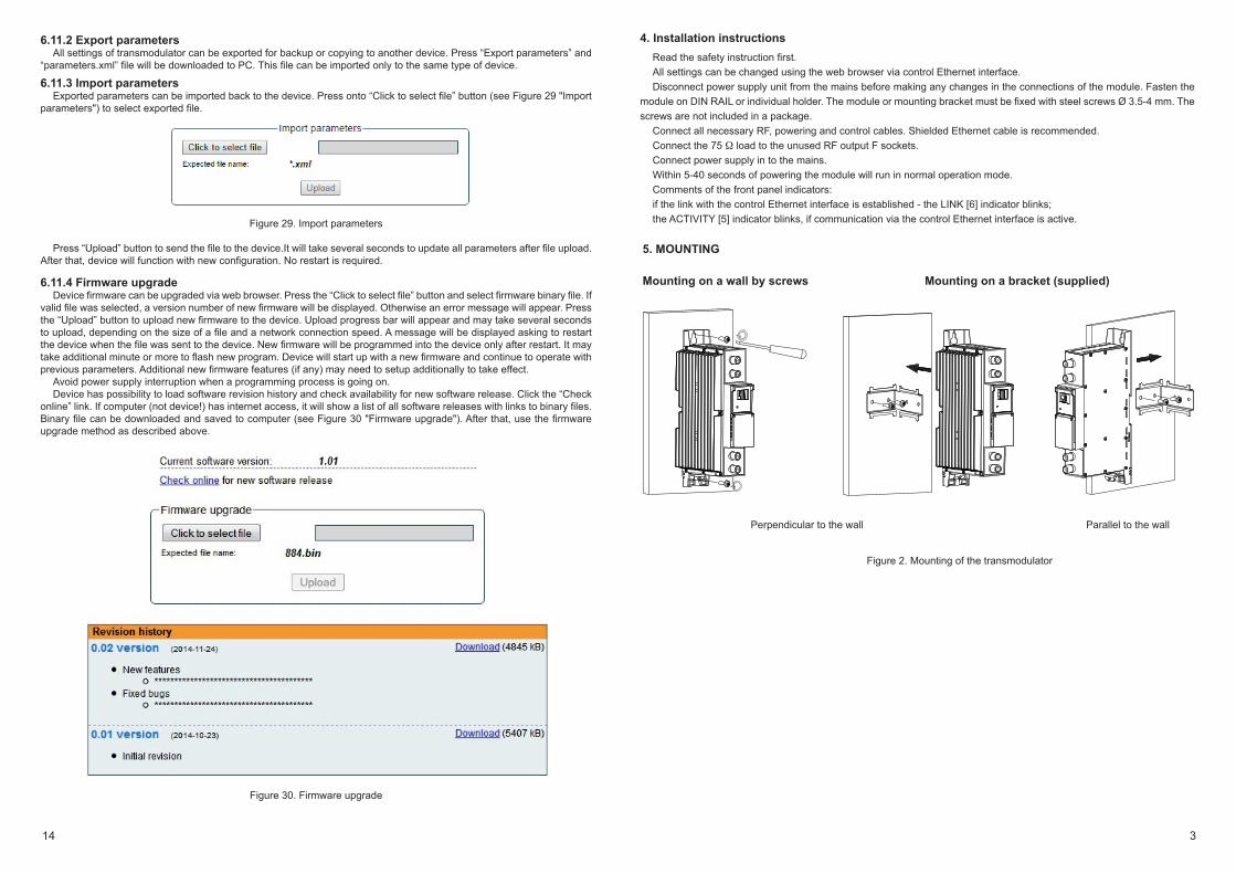
4. Installation instructionsRead the safety instruction first. All settings can be changed using the web browser via control Ethernet interface. Disconnect power supply unit from the mains before making any changes in the connections of the module. Fasten the
module on DIN RAIL or individual holder. The module or mounting bracket must be fixed with steel screws Ø 3.5-4 mm. The screws are not included in a package.
Connect all necessary RF, powering and control cables. Shielded Ethernet cable is recommended.Connect the 75 load to the unused RF output F sockets. Connect power supply in to the mains. Within 5-40 seconds of powering the module will run in normal operation mode. Comments of the front panel indicators: if the link with the control Ethernet interface is established - the LINK [6] indicator blinks;the ACTIVITY [5] indicator blinks, if communication via the control Ethernet interface is active.
5. MOUNTING
Mounting on a wall by screws Mounting on a bracket (supplied)
Perpendicular to the wall Parallel to the wall
Figure 2. Mounting of the transmodulator
314
6.11.2 Export parametersAll settings of transmodulator can be exported for backup or copying to another device. Press “Export parameters” and
“parameters.xml” file will be downloaded to PC. This file can be imported only to the same type of device.
6.11.3 Import parametersExported parameters can be imported back to the device. Press onto “Click to select file” button (see Figure 29 "Import
parameters") to select exported file.
Figure 29. Import parameters
Press “Upload” button to send the file to the device.It will take several seconds to update all parameters after file upload. After that, device will function with new configuration. No restart is required.
6.11.4 Firmware upgrade Device firmware can be upgraded via web browser. Press the “Click to select file” button and select firmware binary file. If
valid file was selected, a version number of new firmware will be displayed. Otherwise an error message will appear. Press the “Upload” button to upload new firmware to the device. Upload progress bar will appear and may take several seconds to upload, depending on the size of a file and a network connection speed. A message will be displayed asking to restart the device when the file was sent to the device. New firmware will be programmed into the device only after restart. It may take additional minute or more to flash new program. Device will start up with a new firmware and continue to operate with previous parameters. Additional new firmware features (if any) may need to setup additionally to take effect.
Avoid power supply interruption when a programming process is going on.Device has possibility to load software revision history and check availability for new software release. Click the “Check
online” link. If computer (not device!) has internet access, it will show a list of all software releases with links to binary files. Binary file can be downloaded and saved to computer (see Figure 30 "Firmware upgrade"). After that, use the firmware upgrade method as described above.
Figure 30. Firmware upgrade
1. 2.
Mounting on DIN rail
Figure 5. Mounting or removing to/from DIN rail of plastic spacers (supplied).
Figure 3. Mounting to DIN rail
Figure 4. Mounting from DIN rail
134
DC IN 12V- +
TERRA
RESET
ETHERNET
tdq420
DC IN 12V- +
TERRA
RESET
ETHERNET
tdq420
DC IN 12V- +
TERRA
RESET
ETHERNET
tdq420
Figure 27. CA information and menu tables
6.11 System menu This menu tab contains following submenu items: “Event logs”, “Export parameters”, “Import parameters”, “Firmware
upgrade”, “User management”, “Restore defaults“, “ Reset the device“, “Language”. Mouse over to show the list of this submenu.
6.11.1 Event logs Various important events, errors, warnings will be logged into the system Figure 28 "Event logs". Each record has an
event type, which can be used to filter particular messages. Just select checkboxes in the „Logs filtering“ table and press „apply“. Other messages will be hidden.
„Erase logs“ button will erase all logs from the system. “Export logs” button forms the file (log.html) which will be downloaded to PC.Each record has a log time when the event appeared. Refer to 6.11.8 "Date and time settings" for instructions how to
configure "Time settings".
Figure 28. Event logs
512
6. Operating
6.1 Initial configurationAll modules leave the factory with this control over Ethernet interface IP address: 192.168.1.10. In order to avoid conflicts
with other IP addresses, it is necessary to perform an initial configuration in the local mode. Subsequently, it will be possible to access the module via local area network (LAN), either to change the configuration or to check the operating status.
The modules leave the factory with the following control over Ethernet interface TCP/IP configuration:IP address of the module: 192.168.1.10Subnet mask: 255.255.255.0Default Gateway: 192.168.1.1
To access each module, use a personal computer (PC) equipped with an Ethernet card and RJ-45 cable (CAT-5E or CAT-6). The IP address of the PC/MAC must be configured within the following range: 192.168.1.2 - 192.168.1.254 (do not use 192.168.1.10, since this is the IP address of the module to be configured). To start the configuration of the module, open your web browser and type in the following direction: http://192.168.1.10. The login prompt will appear on the screen (see Figure 6).
Figure 6. Login window
Access to the module is protected by user name and password. The default user name and password is admin. Enter the user name and password and click on "Login" button.
NOTE*: the default password - admin - can (and must) be changed as explained in the section 6.11.5 "User management". During initial configuration you need to change the default control interface TCP/IP configuration as explained in the section 6.8 "IP settings".
NOTE**: If you are using Internet Explorer Web browser, supported versions are version 10 or higher.Control interface IP address reset to default procedure: press the "RESET" [7] button for more than 3 seconds and release
it. After this operation the control interface IP address will be set to 192.168.1.10, user name and password set to admin.
6.2 General configurationInitial Web interface screen
The first screen that appears when the module accessed is the "Main" window, which gives general information on the device.
Figure 7. General information screen
In the top of each configuration screen you will see a main menu tabs [1]. Using it, you can switch between the different configuration menu. The tab highlighted in yellow shows which menu is active at a given moment. The "System menu" tab contains several submenu items. Also common elements for all screens are module title [2] and login information strings [3]. The module title can be changed after pressing the "Change" button in the "Device information" table. Pressing on the "Logout" string you can logout from module control.
[1]
[3]
[2]
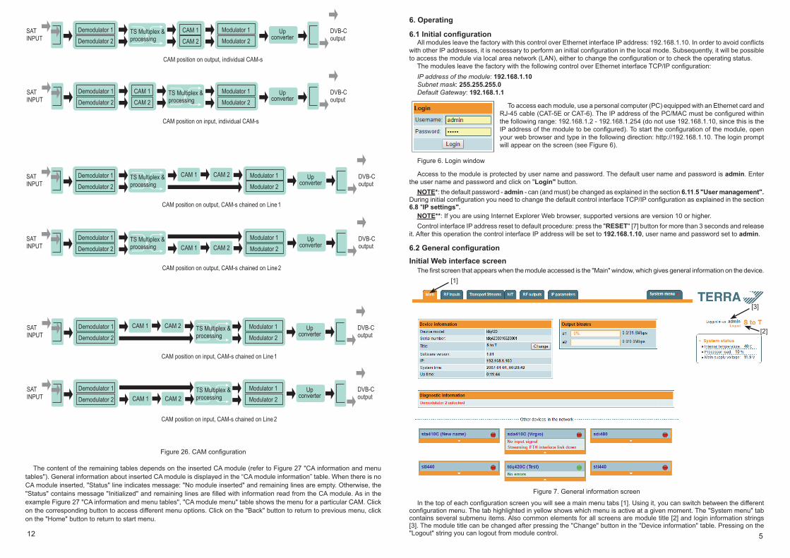
Figure 26. CAM configuration
The content of the remaining tables depends on the inserted CA module (refer to Figure 27 "CA information and menu tables"). General information about inserted CA module is displayed in the “CA module information” table. When there is no CA module inserted, "Status" line indicates message: "No module inserted" and remaining lines are empty. Otherwise, the "Status" contains message "Initialized" and remaining lines are filled with information read from the CA module. As in the example Figure 27 "CA information and menu tables", "CA module menu" table shows the menu for a particular CAM. Click on the corresponding button to access different menu options. Click on the "Back" button to return to previous menu, click on the "Home" button to return to start menu.
SATINPUT
q Demodulator 1
Demodulator 2
q
Upconverter
q
q DVB-Coutput
q
q
qModulator 1
Modulator 2
CAM position on output, individual CAM-s
CAM position on input, individual CAM-s
qqTS Multiplex &
processing
SATINPUT
q Demodulator 1
Demodulator 2
q
Upconverter
q
q DVB-Coutput
q
q
qModulator 1
Modulator 2
CAM 1
CAM 2
qq TS Multiplex &
processing
CAM 1
CAM 2
SATINPUT
q Demodulator 1
Demodulator 2
q
q
Upconverter
q
q DVB-Coutput
q
q
qModulator 1
Modulator 2
CAM position on output, CAM-s chained on Line 1
qqq TS Multiplex &
processing
CAM 1
q
CAM 2
SATINPUT
q Demodulator 1
Demodulator 2
q
q
Upconverter
q
q DVB-Coutput
q
q
qModulator 1
Modulator 2
CAM position on output, CAM-s chained on Line 2
q
qq TS Multiplex &
processing CAM 1
q
CAM 2
SATINPUT
q Demodulator 1
Demodulator 2
q
Upconverter
q
q DVB-Coutput
q
q
qModulator 1
Modulator 2
CAM position on input, CAM-s chained on Line 1
TS Multiplex & processing
CAM 1
q
CAM 2
CAM position on input, CAM-s chained on Line 2
CAM 1
q
CAM 2
SATINPUT
q Demodulator 1
Demodulator 2
q
Upconverter
q
q DVB-Coutput
q
q
qModulator 1
Modulator 2
TS Multiplex & processing
6 11
6.8 IP settings
All device IP settings can be configured here – IP address, subnet mask, gateway, DNS (Domain Name System), see Figure 23 "IP settings table".IP parameters will be updated immediately after pressing „Update“ button and redirect to new location. NOTE: Press the RESET and default IP button for more than three seconds to set default IP address of the control Ethernet interface (see Figure 1 "External view of the module").
Figure 23. IP settings table
6.9 E-mail-settingsThe device can send e-mail reports if errors were detected. SMTP protocol is used for that. Figure 24 “E-mail-settings table” shows parameters related to this feature. “Enable e-mail error report” checkbox enables error monitoring. All errors within “timeout” period will be gathered, and send to the e-mail address, provided in “Receiver e-mail address” input box. Comma separated e-mail addresses can be used to send report to multiple addresses. The timer will be started as soon, as the first error is detected, and stopped when e-mail is sent. The timer will be restarted again if a new error will appear.“Sender e-mail address” can be used as authentication in the SMTP server side.SSL (SMTPS) protocol is not supported.
Figure 24. E-mail-settings table
6.10 CAM settings
Figure 25. Configuration of CA modules
This screen consists of three tables: " Configuration of CA modules ", "CA module information" and "CA module menu". In the "Configuration of CA modules" table CAM restart function in case of descrambling error can be enabled. It is recommended to turn off this option if not activated conditional access card has been inserted. “CAM settings” and “CAM position” parameters changes the flow of TS. Channel 1 and channel 2 streams can be descrambled separately by selecting “Invidual CAM-s” or chained on the line 1 or 2 as shown in Figure 25. CAM position can be changed from output to input. For example: “CAM position” is set to “on input” and “CAM settings” is set to “Chained on line 1”. This means that Channel 1 input’s stream travels through CAM 1 followed by CAM 2, then goes to MUX and finally to Modulator, see Figure 26.
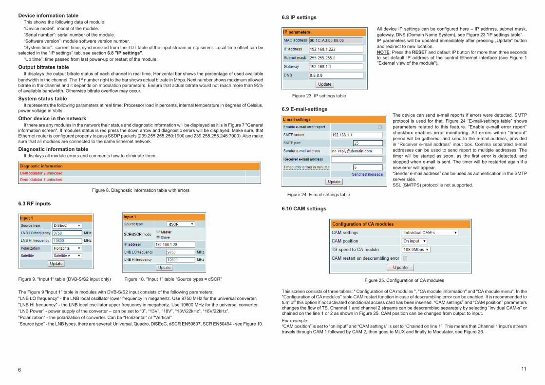
Device information tableThis shows the following data of module:“Device model”: model of the module.“Serial number”: serial number of the module.“Software version”: module software version number. “System time”: current time, synchronized from the TDT table of the input stream or ntp server. Local time offset can be
selected in the "IP settings" tab, see section 6.8 "IP settings". “Up time”: time passed from last power-up or restart of the module.
Output bitrates table It displays the output bitrate status of each channel in real time, Horizontal bar shows the percentage of used available
bandwidth in the channel. The 1st number right to the bar shows actual bitrate in Mbps. Next number shows maximum allowed bitrate in the channel and it depends on modulation parameters. Ensure that actual bitrate would not reach more than 95% of available bandwidth. Otherwise bitrate overflow may occur.
System status table It represents the following parameters at real time: Processor load in percents, internal temperature in degrees of Celsius,
power voltage in Volts.
Other device in the network If there are any modules in the network their status and diagnostic information will be displayed as it is in Figure 7 "General
information screen". If modules status is red press the down arrow and diagnostic errors will be displayed. Make sure, that Ethernet router is configured properly to pass SSDP packets (239.255.255.250:1900 and 239.255.255.246:7900). Also make sure that all modules are connected to the same Ethernet network
Diagnostic information tableIt displays all module errors and comments how to eliminate them.
Figure 8. Diagnostic information table with errors
6.3 RF inputs
Figure 9. "Input 1" table (DVB-S/S2 input only) Figure 10. "Input 1" table "Source types = dSCR"
The Figure 9 "Input 1" table in modules with DVB-S/S2 input consists of the following parameters: "LNB LO frequency" - the LNB local oscillator lower frequency in megahertz. Use 9750 MHz for the universal converter. "LNB HI frequency" - the LNB local oscillator upper frequency in megahertz. Use 10600 MHz for the universal converter. “LNB Power” - power supply of the converter – can be set to “0”, “13V”, “18V”, “13V/22kHz”, “18V/22kHz”. "Polarization" - the polarization of converter. Can be "Horizontal" or "Vertical". “Source type” - the LNB types, there are several: Universal, Quadro, DiSEqC, dSCR EN50607, SCR EN50494 - see Figure 10.
710
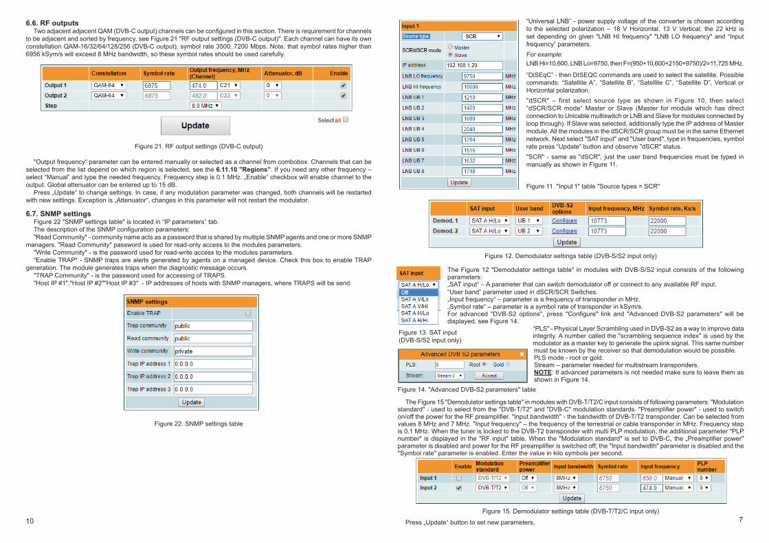
6.6. RF outputsTwo adjacent adjacent QAM (DVB-C output) channels can be configured in this section. There is requirement for channels
to be adjacent and sorted by frequency, see Figure 21 "RF output settings (DVB-C output)". Each channel can have its own constellation QAM-16/32/64/128/256 (DVB-C output), symbol rate 3500..7200 Mbps. Note, that symbol rates higher than 6956 kSym/s will exceed 8 MHz bandwidth, so these symbol rates should be used carefully.
Figure 21. RF output settings (DVB-C output)
"Output frequency“ parameter can be entered manually or selected as a channel from combobox. Channels that can be selected from the list depend on which region is selected, see the 6.11.10 "Regions". If you need any other frequency – select “Manual” and type the needed frequency. Frequency step is 0.1 MHz. „Enable“ checkbox will enable channel to the output. Global attenuator can be entered up to 15 dB.
Press „Update“ to change settings. In case, if any modulation parameter was changed, both channels will be restarted with new settings. Exception is „Attenuator“, changes in this parameter will not restart the modulator.
6.7. SNMP settingsFigure 22 "SNMP settings table" is located in “IP parameters” tab. The description of the SNMP configuration parameters:"Read Community" - community name acts as a password that is shared by multiple SNMP agents and one or more SNMP
managers. "Read Community" password is used for read-only access to the modules parameters. "Write Community" - is the password used for read-write access to the modules parameters. "Enable TRAP" - SNMP traps are alerts generated by agents on a managed device. Check this box to enable TRAP
generation. The module generates traps when the diagnostic message occurs. "TRAP Community" - is the password used for accessing of TRAPS. "Host IP #1","Host IP #2""Host IP #3" - IP addresses of hosts with SNMP managers, where TRAPS will be send.
Figure 22. SNMP settings table
“Universal LNB” - power supply voltage of the converter is chosen according to the selected polarization – 18 V Horizontal, 13 V Vertical; the 22 kHz is set depending on given "LNB HI frequency" "LNB LO frequency" and “Input frequency” parameters. For example: LNB Hi=10,600, LNB Lo=9750, then F=(950+10,600+2150+9750)/2=11,725 MHz.
“DiSEqC” - then DISEQC commands are used to select the satellite. Possible commands: “Satellite A”, “Satellite B”, “Satellite C”, “Satellite D”, Vertical or Horizontal polarization."dSCR" – first select source type as shown in Figure 10, then select “dSCR/SCR mode“ Master or Slave (Master for module which has direct connection to Unicable multiswitch or LNB and Slave for modules connected by loop through). If Slave was selected, additionally type the IP address of Master module. All the modules in the dSCR/SCR group must be in the same Ethernet network. Next select "SAT input" and "User band", type in frequencies, symbol rate press “Update” button and observe "dSCR" status."SCR" - same as "dSCR", just the user band frequencies must be typed in manually as shown in Figure 11.
Figure 11. "Input 1" table "Source types = SCR"
Figure 12. Demodulator settings table (DVB-S/S2 input only)
The Figure 12 "Demodulator settings table" in modules with DVB-S/S2 input consists of the following parameters:„SAT input“ – A parameter that can switch demodulator off or connect to any available RF input.“User band” parameter used in dSCR/SCR Switches.„Input frequency“ – parameter is a frequency of transponder in MHz.„Symbol rate“ – parameter is a symbol rate of transponder in kSym/s.For advanced "DVB-S2 options", press "Configure" link and "Advanced DVB-S2 parameters" will be displayed, see Figure 14.
“PLS" - Physical Layer Scrambling used in DVB-S2 as a way to improve data integrity. A number called the "scrambling sequence index" is used by the modulator as a master key to generate the uplink signal. This same number must be known by the receiver so that demodulation would be possible.PLS mode - root or gold.Stream – parameter needed for multistream transponders.NOTE: If advanced parameters is not needed make sure to leave them as shown in Figure 14.
Figure 14. "Advanced DVB-S2 parameters" table
The Figure 15 "Demodulator settings table" in modules with DVB-T/T2/C input consists of following parameters: "Modulation standard" - used to select from the "DVB-T/T2" and "DVB-C" modulation standards. "Preamplifier power" - used to switch on/off the power for the RF preamplifier. "Input bandwidth" - the bandwidth of DVB-T/T2 transponder. Can be selected from values 8 MHz and 7 MHz. "Input frequency" – the frequency of the terrestrial or cable transponder in MHz. Frequency step is 0.1 MHz. When the tuner is locked to the DVB-T2 transponder with multi PLP modulation, the additional parameter "PLP number" is displayed in the "RF input" table. When the "Modulation standard" is set to DVB-C, the „Preamplifier power" parameter is disabled and power for the RF preamplifier is switched off; the "Input bandwidth" parameter is disabled and the "Symbol rate" parameter is enabled. Enter the value in kilo symbols per second.
Figure 15. Demodulator settings table (DVB-T/T2/C input only)
Press „Update“ button to set new parameters.
Figure 13. SAT input(DVB-S/S2 input only)
98
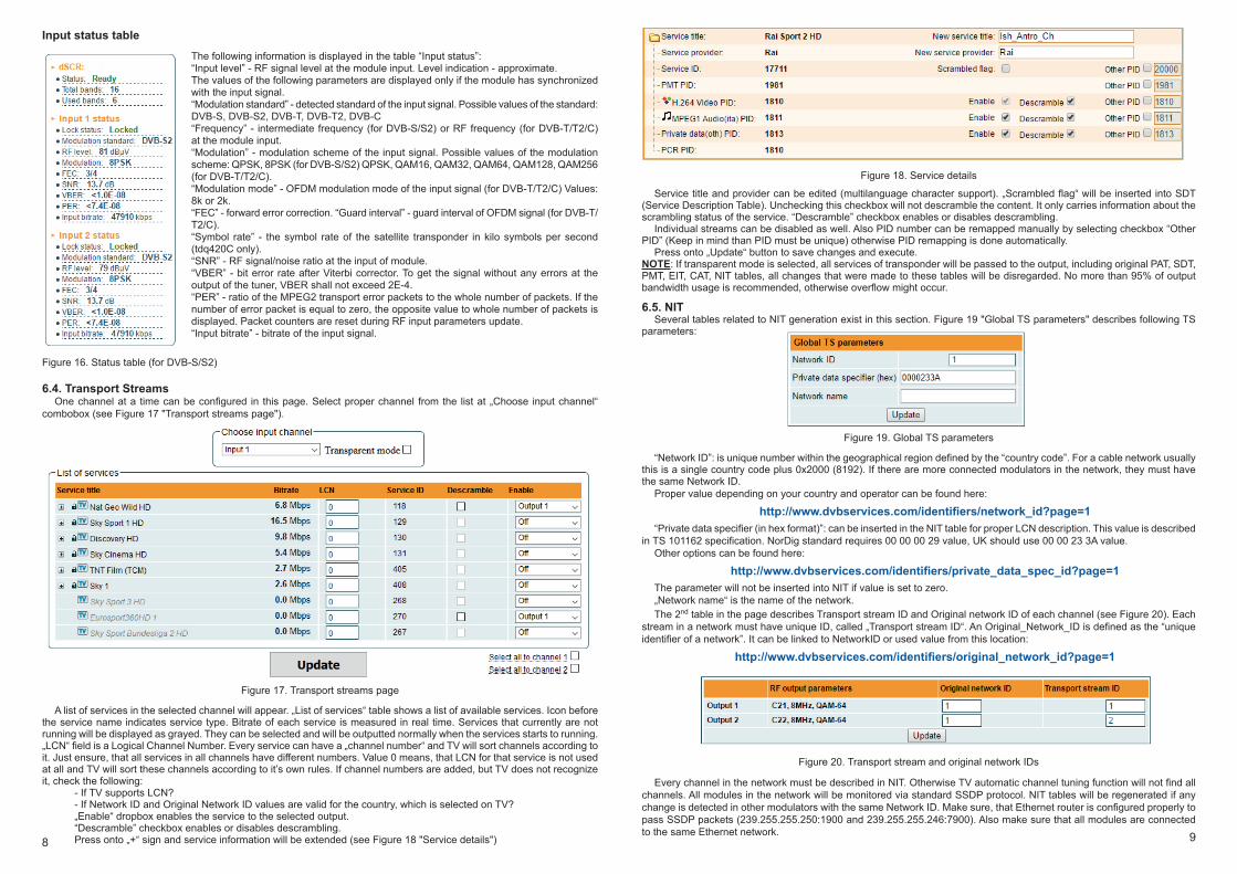
Input status table The following information is displayed in the table “Input status”:“Input level” - RF signal level at the module input. Level indication - approximate. The values of the following parameters are displayed only if the module has synchronized with the input signal. “Modulation standard” - detected standard of the input signal. Possible values of the standard: DVB-S, DVB-S2, DVB-T, DVB-T2, DVB-C “Frequency” - intermediate frequency (for DVB-S/S2) or RF frequency (for DVB-T/T2/C) at the module input. “Modulation” - modulation scheme of the input signal. Possible values of the modulation scheme: QPSK, 8PSK (for DVB-S/S2) QPSK, QAM16, QAM32, QAM64, QAM128, QAM256 (for DVB-T/T2/C). “Modulation mode” - OFDM modulation mode of the input signal (for DVB-T/T2/C) Values: 8k or 2k. “FEC” - forward error correction. “Guard interval” - guard interval of OFDM signal (for DVB-T/T2/C).“Symbol rate” - the symbol rate of the satellite transponder in kilo symbols per second (tdq420C only). “SNR” - RF signal/noise ratio at the input of module. “VBER” - bit error rate after Viterbi corrector. To get the signal without any errors at the output of the tuner, VBER shall not exceed 2Е-4. “PER” - ratio of the MPEG2 transport error packets to the whole number of packets. If the number of error packet is equal to zero, the opposite value to whole number of packets is displayed. Packet counters are reset during RF input parameters update. “Input bitrate” - bitrate of the input signal.
Figure 16. Status table (for DVB-S/S2)
6.4. Transport StreamsOne channel at a time can be configured in this page. Select proper channel from the list at „Choose input channel“
combobox (see Figure 17 "Transport streams page").
Figure 17. Transport streams page
A list of services in the selected channel will appear. „List of services“ table shows a list of available services. Icon before the service name indicates service type. Bitrate of each service is measured in real time. Services that currently are not running will be displayed as grayed. They can be selected and will be outputted normally when the services starts to running. „LCN“ field is a Logical Channel Number. Every service can have a „channel number“ and TV will sort channels according to it. Just ensure, that all services in all channels have different numbers. Value 0 means, that LCN for that service is not used at all and TV will sort these channels according to it’s own rules. If channel numbers are added, but TV does not recognize it, check the following:
- If TV supports LCN?- If Network ID and Original Network ID values are valid for the country, which is selected on TV?„Enable“ dropbox enables the service to the selected output.“Descramble” checkbox enables or disables descrambling.Press onto „+“ sign and service information will be extended (see Figure 18 "Service details")
Figure 18. Service details
Service title and provider can be edited (multilanguage character support). „Scrambled flag“ will be inserted into SDT (Service Description Table). Unchecking this checkbox will not descramble the content. It only carries information about the scrambling status of the service. “Descramble” checkbox enables or disables descrambling.
Individual streams can be disabled as well. Also PID number can be remapped manually by selecting checkbox “Other PID” (Keep in mind than PID must be unique) otherwise PID remapping is done automatically.
Press onto „Update“ button to save changes and execute.NOTE: If transparent mode is selected, all services of transponder will be passed to the output, including original PAT, SDT, PMT, EIT, CAT, NIT tables, all changes that were made to these tables will be disregarded. No more than 95% of output bandwidth usage is recommended, otherwise overflow might occur.
6.5. NITSeveral tables related to NIT generation exist in this section. Figure 19 "Global TS parameters" describes following TS
parameters:
Figure 19. Global TS parameters
“Network ID”: is unique number within the geographical region defined by the “country code”. For a cable network usually this is a single country code plus 0x2000 (8192). If there are more connected modulators in the network, they must have the same Network ID.
Proper value depending on your country and operator can be found here:
http://www.dvbservices.com/identifiers/network_id?page=1“Private data specifier (in hex format)”: can be inserted in the NIT table for proper LCN description. This value is described
in TS 101162 specification. NorDig standard requires 00 00 00 29 value, UK should use 00 00 23 3A value.Other options can be found here:
http://www.dvbservices.com/identifiers/private_data_spec_id?page=1The parameter will not be inserted into NIT if value is set to zero.„Network name“ is the name of the network.The 2nd table in the page describes Transport stream ID and Original network ID of each channel (see Figure 20). Each
stream in a network must have unique ID, called „Transport stream ID“. An Original_Network_ID is defined as the “unique identifier of a network”. It can be linked to NetworkID or used value from this location:
http://www.dvbservices.com/identifiers/original_network_id?page=1
Figure 20. Transport stream and original network IDs
Every channel in the network must be described in NIT. Otherwise TV automatic channel tuning function will not find all channels. All modules in the network will be monitored via standard SSDP protocol. NIT tables will be regenerated if any change is detected in other modulators with the same Network ID. Make sure, that Ethernet router is configured properly to pass SSDP packets (239.255.255.250:1900 and 239.255.255.246:7900). Also make sure that all modules are connected to the same Ethernet network.