Embed Size (px)
Citation preview

41-133S Directional Overcurrent Ground RelaysTypes IRP, IRC and IRD
electromagnet; a moving assembly; and a moldedbridge.
The frame serves as the mounting structure for themagnetic core. The magnetic core which houses thelower pin bearing is secured to the frame by a lockingnut. The bearing can be replaced, if necessary, with-out having to remove the magnetic core from theframe.
The electromagnet has two series-connected polariz-ing coils mounted diametrically opposite one another;two series-connected operating coils mounted dia-metrically opposite one another; two magneticadjusting plugs; upper and lower adjusting plug clips,and two locating pins. The locating pins are used toaccurately position the lower pin bearing, which ismounted on the frame, with respect to the upper pinbearing, which is threaded into the bridge. The elec-tromagnet is secured to the frame by four mountingscrews.
The moving element assembly consists of a spiralspring, contact carrying member, and an aluminumcylinder assembled to a molded hub which holds theshaft. The shaft has removable top and bottom jewelbearings. The shaft rides between the bottom pinbearing and the upper pin bearing with the cylinderrotating in an air gap formed by the electromagnetand the magnetic core.
The bridge is secured to the electromagnet andframe by two mounting screws. In addition to holdingthe upper pin bearing, the bridge is used for mount-ing the adjustable stationary contact housing. Thestationary contact housing is held in position by aspring type clamp. The spring adjuster is located onthe underside of the bridge and is attached to themoving contact arm by a spiral spring. The springadjuster is also held in place by a spring type clamp.
With the contacts closed, the electrical connection ismade through the stationary contact housing clamp,to the moving contact, through the spiral spring out tothe spring adjuster clamp.
2.3 AUXILIARY SWITCH (CS-1 OR TR-1)
The CS-1 switch is a small solenoid type dc switch. Acylindrical plunger, with a silver disc mounted on itslower end, moves in the core of the solenoid. As theplunger travels upward, the disc bridges the silverstationary contacts.
The TR-1 switch is a telephone relay. A tapped resis-tor is used to enable one to use the auxiliary switchon a 24, 48, 125 or 250 volt dc system connected perFigure 26, page 40. The operation of the CS-1 orTR-1 switch is controlled by the directional unit (D)which in turn directionally controls the time-overcur-rent unit (CO). When sufficient power flows in thetripping direction, the auxiliary switch operates andbridges the lag coil of the time-overcurrent unit (CO)permitting this unit to operate.
2.4 INSTANTANEOUS OVERCURRENT UNIT (I)
The instantaneous overcurrent unit is similar in con-struction to the directional unit. The time phase rela-tionship of the two air gap fluxes necessary for thedevelopment of torque, is achieved by means of acapacitor connected in series with one pair of polewindings.
The normally-closed contact of the directional unit isconnected across one pair of pole windings of theinstantaneous overcurrent unit as shown in the inter-nal schematics. This arrangement short-circuits theoperating current around the pole windings, prevent-ing the instantaneous overcurrent unit from develop-ing torque. If the directional unit should pick up for afault, this short-circuit is removed, allowing theinstantaneous overcurrent contact to commenceclosing almost simultaneously with the directionalcontact for high speed operation. Total operatingtime is shown in Figures 23 (page 38) and 24 (page38).
2.5 INSTANTANEOUS OVERCURRENT UNIT TRANSFORMER
This transformer is of the saturating type for limitingthe energy to the instantaneous overcurrent unit athigher values of fault current and to reduce ct bur-den. The primary winding is tapped and these tapsare brought out to a tap block for ease in changingthe pick-up of the instantaneous overcurrent unit.The use of a tapped transformer provides approxi-mately the same energy level at a given multiple ofpickup current for any tap setting, resulting in onetime curve throughout the range of the relay.
Across the secondary is connected a non-linearresistor known as a varistor. The effect of the varistoris to reduce the voltage peaks applied to the overcur-rent unit and phase shifting capacitor.
2

41-133SDirectional Overcurrent Ground RelaysTypes IRP, IRC and IRD
3.0 CHARACTERISTICS
The time characteristics of the directional overcurrentrelays are designated by specific numbers as indi-cated below (e.g., IRD-8).
Time Characteristics Designation
Short Time . . . . . . . . . . . . . . . . . . . . 2Long Time . . . . . . . . . . . . . . . . . . . . 5Definite Time . . . . . . . . . . . . . . . . . . . 6Moderately Inverse Time . . . . . . . . . . . 7Inverse Time . . . . . . . . . . . . . . . . . . . 8Very Inverse Time . . . . . . . . . . . . . . . 9Extremely Inverse Time . . . . . . . . . . . 11
The relays are available in the following currentranges:
Instantaneous Overcurrent Unit
Time Overcurrent Unit
The tap value is the minimum current required to justclose relay contacts.
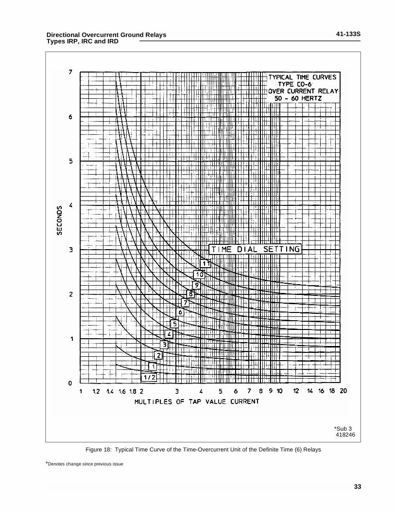
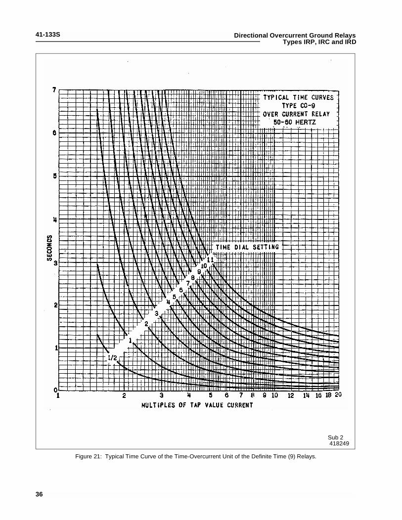
The time vs. current characteristics for the time-over-current unit are shown in Figures 16 to 22 (page 31to page 37). These characteristics give the contactclosing time for the various time dial settings whenthe indicated multiples of tap value current areapplied the relay.
4.0 TIME CURVES
The times curves for the IRD relay are shown in Fig-ures 23 (page 38) and 24 (page 38). Figure 23 con-sists of three curves which are:
1. Directional Unit opening times for currentand voltage polarized.
2. Directional Unit closing time for current andvoltage polarized.
3. Directional Unit closing time for 1 volt, volt-age polarized.
Figure 24 shows the instantaneous overcurrent unitclosing time.
The voltage polarized curve B begins to deviate fromcurve A for less than 5 volts.
Both the directional unit and the overcurrent unitmust operate before the trip circuit can be completed.Hence, the unit which takes the longer time to oper-ate determines when the breaker will be tripped. Theovercurrent unit contacts cannot operate until theback contacts of directional unit open; therefore, thetotal time for overcurrent unit to operate is its closingtime given in Figure 24 (page 38) plus the directionalunit opening time given in Figure 23. The total clos-ing time for the directional unit is given in Figure 23.The two examples below will serve to illustrate theuse of the curves.
Example 1: Using the formulas and definition of sym-bols on Figure 23,
Let: Ipol = 2 amps.Iop = 2.31 amps.
Tap Value (T) = 0.5 amp.φ - 40° = 0°
(For timing unit, assume CO-9 with 1/2 timedial setting)
For current polarized relay:
Referring to Figure 23 at multiples of product pickupof 18.5, the directional unit operating time is about 11ms, and the closing time for this unit is 56 ms.
Range Taps
0.5-2 Amps 0.5 0.75 1.0 1.25 1.5 2
1-4 1.0 1.5 2.0 2.5 3.0 4.0
2-8 2 3 4 5 6 8
4-16 4 6 8 9 12 16
10-40 10 15 20 24 30 40
20-80 20 30 40 48 60 80
Range Taps
.5-2.5 0.5 0.6 0.8 1.0 1.5 2.0 2.5
2-6 2 2.5 3 3.5 4 5 6
4-12 4 5 6 7 8 10 12
MPPlop lpol φ 40°–( )cos
0.25--------------------------------------------------=
MPP2.31( ) 2( )
0.25----------------------- 18.5= =
3

41-133S Directional Overcurrent Ground RelaysTypes IRP, IRC and IRD
For overcurrent unit:
Entering the curve in Figure 24 at multiples of pickupequal to 4.6, the closing time for instantaneous over-current is 16 ms. However, the total operating timefor the overcurrent unit is 16 plus 11, which is theopening time of back contacts of the directional unit,or 27 ms total operating time for overcurrent unit. Thetotal time for directional unit is 56 ms, and, since thisis the longest time, 56 ms is the total operating timeof the instantaneous overcurrent circuit.
Entering the curve in Figure 21(page 36) at 4.6, the1/2 time dial setting gives 140 ms. The total time forthe time-overcurrent circuit is 56 ms directional unittime plus 16 ms time Aux plus 140 ms = 212 ms.
Example 2:
Let: Ipol = 20 ampsIop = 23.1 amps
T (tap) = 1 ampφ - 40° = 0°
Entering Figure 23, (page 38) the directional unitclosing time is 12 ms, and the opening time of itsback contacts is 1 ms. The total operating time forthe directional unit is 12 ms.
For overcurrent unit:
Referring to Figure 24, (page 38) the overcurrent unitcontact closing time is about 14 ms. Therefore, thetotal operating time for this unit is 14 plus 1 = 15 ms.In this case the total operating time of relay is 15 ms.
Figure 21 (page 36) gives an operating time of about50 ms. The time-overcurrent circuit is 12 plus16 plus50 ms = 78 ms.
4.1 TRIP CIRCUIT
The relay contacts will safely close 30 amperes at
250 volts dc and the seal-in contacts of the indicatingcontactor switches will safely carry this current longenough to trip a circuit breaker.
The indicating contactor switch has two taps that pro-vide a pickup setting of 0.2 or 2 amperes. To changetaps requires connecting the lead located in front ofthe tap block to the desired setting by means of ascrew connection.
4.2 CONTACTS
The moving contact assembly has been factoryadjusted for low contact bounce performance andshould not be changed.
The set screw in each stationary contact has beenfactory adjusted for optimum follow and this adjust-ment should not be disturbed.
4.3 TRIP CIRCUIT CONSTANTS
Indicating Contactor Switch
0.2 ampere tap - 6.5 ohms dc resistance2.0 ampere tap - 0.15 ohms dc resistance
4.4 AUXILIARY SWITCH (CS-1 OR TR-1)
The CS-1 switch has a dc resistance of 1165 ohms.The TR-1 telephone relay has a dc resistance of1500 ohms.
4.5 TYPE IRP RELAY
The IRP relay is designed for potential polarizationand has its maximum torque when the current lagsthe voltage by approximately 60 degrees. The shift-ing of the maximum torque angle is accomplished bythe use of an internally mounted phase shifter asshown in the internal schematic.
The directional unit minimum pick-up is approxi-mately 1 volt and 2 amperes at its maximum torqueangle for the directional units used with the 0.5 to 2.5and 2 to 6 ampere range time overcurrent units. Forthe directional units used with the 4-12 ampere rangetime overcurrent units the minimum pick-up is 1 voltand 4 amperes.
4.6 TYPE IRC RELAY
The IRC relay is designed for current polarizationand has its maximum torque when the operating cur-rent leads the polarizing current by approximately40°.
The directional unit minimum pick-up is 0.5 ampere
Multiples of pickuplopT
--------2.310.5---------- 4.6= = =
MPPlop lpol φ 40°–( )cos
0.25-----------------------------------------------------=
MPP20( ) 23.1( )
0.25-------------------------- 1850= =
Multiples of pickuplopT
--------23.1
1---------- 23.1= = =
4

41-133SDirectional Overcurrent Ground RelaysTypes IRP, IRC and IRD
in each winding at the maximum torque angle for thedirectional units used with the 0.5 to 2.5 and 2 to 6ampere range time overcurrent units. For the direc-tional units used with the 4-12 ampere range timeovercurrent units the minimum pickup is 1 ampere.
4.7 TYPE IRD RELAY
The IRD relay utilizes a directional unit similar to theIRC relay and a directional unit and phase-shiftingcircuit similar to those in the IRP relay.
The current-polarized directional unit of the IRD relayoperates on residual currents while the poten-tial-polarized directional unit of the IRD relay oper-ates on residual voltage and residual current.
For the directional units used with the 0.5 to 2 and 2to 6 ampere time overcurrent units, the minimumpick-up of the current polarized unit is 0.5 ampere ineach winding at the maximum torque angle. The min-imum pick-up for the voltage polarized unit is 1 voltand 2 amperes with the current lagging voltage by60°.
For the directional units used with the 4 to 12 ampererange time overcurrent units, the minimum pick-up is1 ampere for the current-polarized directional unitand 1 volt and 4 amperes for the voltage-polarizeddirectional unit.
5.0 SETTINGS
5.1 TIME OVERCURRENT UNIT (CO)
The time overcurrent unit settings can be definedeither by tap setting and dial position or by tap settingand a specific time of operation at some current mul-tiple of the tap setting (e.g. 4 tap setting, 2 time dialposition or 4 tap setting, 0.6 seconds at 6 times tapvalue current).
To provide selective circuit breaker operation, a mini-mum coordinating time of 0.3 seconds plus circuitbreaker time is recommended between the relaybeing set and the relays with which coordination is tobe effected.
The connector screws on the tap plate above thetime dial makes connections to various turns on theoperating coil. By placing this screw in the varioustap plate holes, the relay will just close its contacts atthe corresponding current 4-5-6-7-8-10-12 amperes,or as marked on the tap plate.
Since the tap block connector screw carriesoperating current, be sure that the screw isturned tight.
5.2 INSTANTANEOUS RECLOSING
The factory adjustment of the CO unit contactsprovides a contact follow. Where circuit breakerreclosing will be initiated immediately after a trip bythe CO contact, the time of the opening of the con-tacts should be a minimum. This condition isobtained by loosening the stationary contact mount-ing screw, removing the contact plate and thenreplacing the plate with the bent end resting againstthe contact spring. With this change and the contactmounting screw tightened, the stationary contact willrest solidly against its backstop.
5.3 INSTANTANEOUS OVERCURRENT UNIT (I)
The only setting required is the pickup current settingwhich is made by means of the connector screwlocated on the tap plate. By placing the connectorscrew in the desired tap, the relay will just close itscontacts at the tap value current.
Since the tap block connector screw carriesoperating currents, be sure that the screw isturned tight.
5.4 DIRECTIONAL UNITS (D)
No setting is required.
5.5 INDICATING CONTACTOR SWITCH (ICS/I AND ICS/T)
The setting required on the ICS units is the selectionof the 0.2 or 2.0 ampere tap setting. This selection ismade by connecting the lead located in front of thetap block to the desired setting by means of the con-necting screw.
5.6 AUXILIARY SWITCH (CS-1 OR TR-1)
No setting required on the auxiliary switch except forthe selection of the required 24, 48, 125 or 250 volt-age on the tapped resistor. This connection can bemade by referring to Figure 26 (page 40).
! CAUTION
! CAUTION
5

41-133S Directional Overcurrent Ground RelaysTypes IRP, IRC and IRD
6.0 INSTALLATION
The relays should be mounted on switchboard pan-els or their equivalent in a location free from dirt,moisture, excessive vibration and heat. Mount therelay vertically by means of the rear mounting stud orstuds for the type FT projection case or by means ofthe four mounting holes on the flange for thesemi-flush type FT case. Either the stud or themounting screws may be utilized for grounding therelay. External toothed washers are provided for usein the locations shown on the outline and drilling planto facilitate making a good electrical connectionbetween the relay case, its mounting screws orstuds, and the relay panel. Ground Wires should beaffixed to the mounting screws or studs as requiredfor poorly grounded or insulating panels. Other elec-trical connections may be made directly to the termi-nals by means of screws for steel panel mounting orto the terminal stud furnished with the relay for thickpanel mounting. The terminal stud may be easilyremoved or inserted by locking two nuts on the studand then turning the proper nut with a wrench.
For detail information on the FT case refer to I.L.41-076.
The external ac connections of the directional over-current relays are shown in Figures 13, 14, and 15(on page 28, page 29, and page 30). If no voltagepolarizing source is to be connected to the IRD relay,short-circuit the voltage polarizing circuit at the termi-nals of the relay.
6.1 REVERSED CONTACTS
In installations where the relay could be exposed tounusual shock or jarring, the possibility of inadvertentcontact closure can be reduced by reversing the ori-entation of the directional unit contacts. Contactarrangement and wiring would be reversed on thedirectional unit. Its contact would then mechanicallyclose in a direction opposite to that of the instanta-neous unit contact. Electrical characteristics andexternal connections to the relay would not beaffected. Field modifications can be made per thefollowing procedures.
1. Reverse the leads on the stationary contactsof the directional unit. For the IRD, reversethe leads on both directional units.
2. Reverse the leads to switch jaw terminals 6and 7. For the IRD, also reverse leads toswitch jaw terminals 4 and 5.
3. Move the spring adjuster on each directionalunit such that the left hand contacts arenormally closed.
4. Remove, then reverse the right hand and lefthand stationary contacts on each directionalunit. Adjust the left hand contact until it justmakes with the moving contact, thenadvance it an additional 1/2 turn in. Nowadjust the right hand stationary contact untilit just makes with the moving contact, thenscrew it out 3/4 turn for a contact gap of.020” to .024”.
5. Calibrate each directional unit per proce-dures beginning at section 7.4.1.c.
For relays whose contacts have beenreversed, it is recommended that a sub letter“R” be added to the nameplate at the end ofthe style number to designate that the relayhas reversed contacts. The new schematicsfor modified relays are 9654A56, 9654A57,9654A58.
7.0 ADJUSTMENTS AND MAINTENANCE
The proper adjustments to insure correct operation ofthis relay have been made at the factory. Uponreceipt of the relay, no customer adjustments, otherthan those covered under “SETTINGS” (page 5),should be required.
7.1 ACCEPTANCE CHECK
The following check is recommended to insure thatthe relay is in proper working order.
7.1.1 Instantaneous Overcurrent Unit (I)
a. Contact Gap: The gap between the stationaryand moving contacts with the relay in thede-energized position should be approximately.020”.
b. Minimum Trip Current: The normally-closed con-tact of the directional unit should be blockedopen when checking the pick-up of the overcur-rent unit.
The pick-up of the overcurrent unit can be
6
41-133SDirectional Overcurrent Ground RelaysTypes IRP, IRC and IRD
checked by inserting the tap screw in the desiredtap hole and applying rated tap value current.The contact should close within 5% of tap valuecurrent.
7.1.2 Directional Unit (D)
a. Contact Gap: The gap between the stationarycontact and moving contact with the relay in thedeenergized position should be approximately.020”.
b. Sensitivity: The respective directional unitsshould trip with value of energization and phaseangle relationship as indicated in Table 1 (page10).
c. Spurious Torque Adjustments: There should beno spurious closing torques when the operatingcircuits are energized per Table 2 (page 11) withthe polarizing circuits short circuited for the volt-age polarized units and open-circuited for thecurrent polarized units.
7.1.3 Time Overcurrent Unit (CO)
ContactsThe index mark on the movement frame will coincidewith the “0” mark on the time dial when the stationarycontact has moved through approximately one-half ofits normal deflection. Therefore, with the stationarycontact resting against the backstop, the index markis offset to the right of the “0” mark by approximately.020”. The placement of the various time dial posi-tions in line with the index mark will give operatingtimes as shown on the respective time-currentcurves.
Minimum Trip CurrentSet the time dial to position 6 with the auxiliary switchcontacts blocked closed, alternately apply tap valuecurrent plus 3% and tap value current minus 3%. Themoving contact should leave the backstop at tapvalue current plus 3% and should return to the back-stop at tap value current minus 3%.
Time CurveTable 3 (page 11) shows the time curve calibrationpoints for the various types of relays. With the timedial set to the indicated position, apply the currentsspecified by Table 3 (e.g. for the CO-2, 3 and 20times tap value current) and measure the operatingtime of the relay. The operating times should equalthose of Table 3 plus or minus 5 percent.
7.1.4 Indicating Contactor Switches (ICS/I) and (ICS/T)
a. Close the contacts of the CO and pass sufficientdc current through the trip circuit to close thecontact of (ICS/T). This value of current shouldnot be greater than the particular (ICS/T) tap set-ting being used. The operation indicator targetshould drop freely, bring the letter “T” into view.
b. Close the contacts of the instantaneous overcur-rent unit (I) and the directional unit (D). Pass suf-ficient dc current through the trip circuit to closethe contacts of (ICS/I). This value of currentshould not be greater than the particular (ICS/I)tap setting being used. The operation indicatortarget should drop freely, bringing the letter “I”into view.
7.2 ROUTINE MAINTENANCE
All relays should be inspected periodically and thetime of operation should be checked at least onceevery year or at such other time intervals as may bedictated by experience to be suitable to the particularapplication. The use of phantom loads, in testinginduction-type relays, should be avoided, since theresulting distorted current waveform will produceerror in timing.
All contacts should be periodically cleaned. A contactburnisher #182A836H01 is recommended for thispurpose. The use of abrasive material for cleaningcontacts is not recommended, because of the dangerof embedding small particles in the face of the softsilver and thus impairing the contact.
7.3 CALIBRATION
Use the following procedure for calibrating the relay ifthe relay has been taken apart for repairs or theadjustments have been disturbed. This procedureshould not be used unless it is apparent that the relayis not in proper working order. (See AcceptanceCheck, page 6.)
7.4 INSTANTANEOUS OVERCURRENT UNIT (I)
a. The upper pin bearing should be screwed downuntil there is approximately .025 clearancebetween it and the top of shaft bearing. Theupper pin bearing should then be securelylocked in position with the lock nut. The lowerbearing position is fixed and cannot be adjusted!
7
41-133S Directional Overcurrent Ground RelaysTypes IRP, IRC and IRD
b. The contact gap adjustment for the overcurrentunit is made with the moving contact in the resetposition i.e., against the right side of the bridge.Move in the left-hand stationary contact until itjust touches the moving contact then back off thestationary contact 2/3 of one turn for a gap ofapproximately .020”. The clamp holding the sta-tionary contact housing need not be loosened forthe adjustment since the clamp utilizes aspring-type action in holding the stationary con-tact in position.
c. The sensitivity adjustment is made by varyingthe tension of the spiral spring attached to themoving element assembly. The spring isadjusted by placing a screwdriver or similar toolinto one of the notches located on the peripheryof the of the spring adjuster and rotating it. Thespring adjuster is located on the underside of thebridge and is held in place by a spring typeclamp that does not have to be loosened prior tomaking the necessary adjustments.
Before applying current, block open the nor-mally-closed contact of the directional unit insertthe tap screw in the minimum value tap settingand adjust the spring such that the contacts willclose as indicated by a neon lamp in the contactcircuit when energized with the required current.The pick up of the overcurrent unit with the tapscrew in any other tap should be within 5% of tapvalue.
If adjustment of pick-up current in-between tapsettings is desired insert the tap screw in the nextlowest tap setting and adjust the spring asdescribed. It should be noted that this adjustmentresults in a slightly different time characteristiccurve and burden.
7.4.1 Directional Unit (D) In the type IRP and IRC relays the directional unit isthe lower cylinder unit. In the type IRD the directionalunits are the lower and middle cylinder units.
a. The upper bearing screw should be screweddown until there is approximately .025 clearancebetween it and the top of the shaft bearing. Theupper pin bearing should then be securelylocked in position with the lock nut.
b. Contact gap adjustment for the directional unit ismade with the moving contact in the reset posi-tion, i.e., against the right side of the bridge.
Advance the right hand stationary contact untilthe contacts just close. Then advance the sta-tionary contact an additional one-half turn.
Now move in the left-hand stationary contactuntil it just touches the moving contact. Thenback off the stationary contact 3/4 of one turn fora contact gap of .020” to .024”. The clamp hold-ing the stationary contact housing need not beloosened for the adjustment since the clamp uti-lizes a spring-type action in holding the station-ary contact in position.
c. Insert tap screw of overcurrent unit in highesttap. The sensitivity adjustment is made by vary-ing the tension of the spiral attached to the mov-ing element assembly. The spring is adjusted byplacing a screwdriver or similar tool into one ofthe notches located on the periphery of thespring adjuster and rotating it. The springadjuster is located on the underside of the bridgeand is held in place by a spring type clamp thatdoes not have to be loosened prior to making thenecessary adjustments. Set red mark on core toleft side of cylinder unit and adjust spring to justreset.
The spring is to be adjusted such that the con-tacts will close as indicated by a neon lamp in thecontact circuit when energized with the requiredcurrent and voltage as shown in Table 1 (page10). This table indicates that the spring can beadjusted when the phase angle relationshipbetween the operating circuit and the polarizingcircuit is at the maximum torque angle or whenthe circuit relationship has the operating andpolarizing circuits in phase.
d. The magnetic plugs are used to reverse anyunwanted spurious torques that may be presentwhen the relay is energized on current or voltagealone.
The reversing of the spurious torques is accom-plished by using the adjusting plugs in the follow-ing manner:
1. Voltage circuit terminals on the voltagepolarized relays (IRP and IRD voltage polar-ized unit) are short-circuited.
2. The polarizing circuits of the current polar-ized relays (IRC and IRD current polarizedunit) are open-circuited.
8
41-133SDirectional Overcurrent Ground RelaysTypes IRP, IRC and IRD
Upon completion of steps 1 or 2 above, apply 5amps and gradually increase to 80 amps. Note,high current to be applied only momentarily.
Plug adjustment is then made per Table 2 (page11) such that the spurious torques are reversed.The plugs are held in position by upper and lowerplug clips. These clips need not be disturbed inany manner when making the necessary adjust-ment.
The magnetic plug adjustment may be utilized topositively close the contacts on current alone.This may be desired on some installations inorder to insure that the relay will always trip thebreaker on zero potential.
e. The core adjustment is used to eliminate anyunwanted spurious torques that may be presentwhen the relay is energized with voltage alone.
Apply 120V AC to terminals 4 (+) and 5 for IRDand terminals 6 (+) and 7 for IRP and adjust coreso that contacts just open.
7.4.2 Time Overcurrent Unit (CO)
Contacts
The index mark on the movement frame will coincidewith the “0” mark on the time dial when the stationarycontact has moved through approximately one-half ofits normal deflection. Therefore, with the stationarycontact resting against the backstop, the index markis offset to the right of the “0” mark by approximately.020”. The placement of the various time dial posi-tions in line with the index mark will give operatingtimes as shown on the respective time-currentcurves.
Minimum trip Current
The adjustment of the spring tension in setting theminimum trip current value of the relay is most con-veniently made with the damping magnet removed.
With the time dial set on “0”, wind up the spiral springby means of the spring adjuster until approximately6-3/4 convolutions show.
Set the relay on the minimum tap setting, the timedial to position 6.
With auxiliary switch (Aux) contacts blocked closed,adjust the control spring tension so that the movingcontact will leave the backstop at tap value current
+1.0% and will return to the backstop at tap valuecurrent -1.0%.
Time Curve Calibration
Install the permanent magnet.
Apply the indicated current per Table 3 (page 11) forpermanent magnet adjustment (e.g. IRP-8, 2 timestap value) and measure the operating time. Adjustthe permanent magnet keeper until the operatingtime corresponds to the value of Table 3.
Apply the indicated current per Table 3 for the elec-tromagnet plug adjustment (e.g. IRP-8, 20 times tapvalue) and measure the operating time. Adjust theproper plug until the operating time corresponds tothe value in Table 3. (Withdrawing the left hand plug,front view increases the operating time and with-drawing the right hand plug, front view, decreasesthe time.) In adjusting the plugs, one plug should bescrewed in completely and the other plug run in orout until the proper operating time has beenobtained.
Recheck the permanent magnet adjustment. If theoperating time for this calibration point has changed,readjust the permanent magnet and then recheck theelectromagnet plug adjustment.
7.5 INDICATING CONTACTOR SWITCHES (ICS/I) AND (ICS/T)
For proper contact adjustment, insert a .030” feelergauge between the core pin and the armature. Holdthe armature closed against the core pin and gaugeand adjust the stationary contacts such that they justmake with the moving contact. Both stationary con-tacts should make at approximately the same time.The contact follow will be approximately 1/64” to3/64”.
Close the contacts of the CO and pass sufficient dccurrent through the trip circuit to close the contacts ofthe (ICS/T). This value of current should not begreater than the particular (ICS/T) tap setting beingused. The operation indicator target should dropfreely bringing the letter “T” into view.
Close contacts of instantaneous overcurrent unit (I)and directional unit (D). Pass sufficient dc currentthrough the trip circuit to close contacts of the (ICS/I).This value of current should not be greater than theparticular (ICS/I) tap setting being used. The opera-
9

41-133S Directional Overcurrent Ground RelaysTypes IRP, IRC and IRD
tion indicator target should drop freely bringing theletter “I” into view.
7.5.1 Auxiliary Switch (CS-1 or TR-1)
Adjust the stationary core of the CS-1 switch for aclearance between the stationary core and the mov-ing core when the switch is picked up. This can bedone by turning the relay upside-down. Then screwup the core screw until the moving core starts rotat-ing. Now back off the core screw until the movingcore stops rotating. This indicates the points wherethe play in the assembly is taken up, and where themoving core just separates from the stationary corescrew. Back off the core screw approximately oneturn and lock in place. This prevents the moving corefrom striking and sticking to the stationary corebecause of residual magnetism. Adjust the contact
clearance for 3/64” by means of the two small nutson either side of the Micarta disc. The TR-1 switchdoes not require adjustment.
Connect lead (A) to proper terminal per Figure 26(page 40). Block directional unit (D) contacts closeand energize trip circuit with rated voltage. Contactsof auxiliary switch (CS-1 or TR-1) should make asindicated by a neon lamp in the contact circuit.
8.0 RENEWAL PARTS
Repair work can be done most satisfactorily at thefactory. However, interchangeable parts can be fur-nished to the customers who are equipped for doingrepair work. When ordering parts, always give thecomplete nameplate data.
10
RELAY TYPETIME-OVERCURRENTAMPERE RATING OF
UNIT
VM
VOL
IRP (VoltageIRD Unit)
IRC (Current
IRD Unit) ∆
.5-2.52-6
4-12
.5-2.52-6
4-12
11
11
† The energization quantities are input quantities†† Maximum torque angle.∆ When normal system conditions limit the curre
by selecting a higher current ct tap to energiz
TADIRECTIONAL
9.0 LIST OF FIGURES
ALUES FOR†
IN. PICKUPPHASE ANGLE RELATIONSHIP
TS AMPERES
2.04.0
4.08.0
0.5.57
1.01.3
l lagging V by 60° ††
l in-phase with V
l lagging V by 60° ††
l in-phase with V
lo leading lp by 40° ††
In-phase
lo leading lp by 40° ††
In-phase
at the relay terminals.
nt to less twice pickup, performance may bee the polarizing circuit.
BLE 1UNIT SENSITIVITY

41-133S
11
Directional Overcurrent Ground RelaysTypes IRP, IRC and IRD
RELAYRATING
CURRENTAMPERES
BOTH PLUGS IN CONDITION ADJUSTMENT
0.5-2.5 Amps2-6 Amps
0.5-2.5 Amps2-6 Amps
4-12 Amps
4-12 Amps
5 - 80
5 - 80
5 - 80
5 - 80
Spurious Torque in contactclosing direction (left front view).
Spurious Torque in contactopening direction (right frontview, contacts remain open).
Right (front-view) plugscrewed out untilSpurious Torque is
Left (front view) plugscrewed out untilSpurious Torque is incontact closing direction.Then the plug is screwedin until Spurious Torqueis reversed.
reversed.
† Short circuit the voltage polarizing at the relay terminals before making the above adjustment.
TABLE 2DIRECTIONAL UNIT CALIBRATION †
PERMANENT MAGNET ADJUSTMENT ELECTROMAGNET PLUGS
TIMEOVERCURRENT
UNIT TYPE
TIMEDIAL
POSITION
CURRENT(MULTIPLES OF
TAP VALUE)
OPERATINGTIME
SECONDS
CURRENT(MULTIPLES OF
TAP VALUE)
OPERATINGTIME
SECONDS
256789
11
6666666
3222222
0.5737.80
2.464.27
13.358.87
11.27
20102020202020
0.2214.30
1.191.111.110.650.24
TABLE 3TIME CURVE CALIBRATION DATA – 60 HERTZ
41-133S
12
Directional Overcurrent Ground RelaysTypes IRP, IRC and IRD
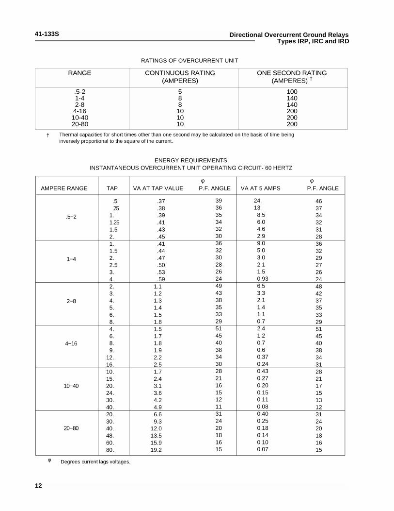
ENERGY REQUIREMENTSINSTANTANEOUS OVERCURRENT UNIT OPERATING CIRCUIT- 60 HERTZ
AMPERE RANGE TAP VA AT TAP VALUE P.F. ANGLE VA AT 5 AMPS P.F. ANGLEφφ
.5−2
1−4
2−8
4−16
10−40
20−80
.5
.751.1.251.52.1.1.52.2.53.4.2.3.4.5.6.8.4.6.8.9.
12.16.10.15.20.24.30.40.20.30.40.48.60.80.
.37
.38
.39
.41
.43
.45
.41
.44
.47
.50
.53
.591.11.21.31.41.51.81.51.71.81.92.22.51.72.43.13.64.24.96.69.3
12.013.515.919.2
3936353432303632302826244943383533 29514540383430282116151211312420181615
24.13.
8.56.04.62.99.05.03.02.11.50.936.53.32.11.41.10.72.41.20.70.60.370.240.430.270.200.150.110.080.400.250.180.140.100.07
463734323128363229272624484237353329514540383431282117151312312420181615
Thermal capacities for short times other than one second may be calculated on the basis of time beinginversely proportional to the square of the current.
Degrees current lags voltages.
†
φ
RANGE CONTINUOUS RATING ONE SECOND RATING(AMPERES) (AMPERES) †
.5-21-42-8
4-1610-4020-80
588101010
100140140200200200
RATINGS OF OVERCURRENT UNIT

41-133S
13
Directional Overcurrent Ground RelaysTypes IRP, IRC and IRD
ENERGY REQUIREMENTS – 60 HERTZDIRECTIONAL UNIT OPERATING CIRCUIT BURDEN
VOLT AMPERES
RelayType
RangeAMPS
ContinuousRating
(Amperes)
One SecondRating†
(Amperes)
PowerFactorAngle φ
AtMinimumTap Value
Current
At 3 TimesMinimumTap Value
Current
At 10 TimesMinimumTap Value
Current
At 20 TimesMinimumTap Value
Current
0.5-2.52-6
4-12
0.5-2.52-6
4-12
0.5-2.52-6
4-12
----12
101012
101012
230230280
230230280
230230280
44.042.531.8
34.534.525.0
45.045.032.4
0.0330.580.64
0.030.440.48
0.071.041.16
0.305.286.12
0.234.084.62
0.599.9
10.8
3.358.070.0
2.848.053.6
6.6106.0121.2
14.2240.0272.0
11.5182.0216.0
26.0420.0472.0
IRC
IRP
IRD
Degrees current lags voltages at tap value current.
Thermal capacities for short times other than one second may be calculated on the basis of timebeing inversely proportional to the square of the current.
φ
†
ENERGY REQUIREMENTS – 60 HERTZ
DIRECTIONAL UNIT POLARIZING CIRCUIT BURDEN
RELAY TYPE RATING VOLT AMPERES ∆ POWER FACTOR ANGLE φ
IRC
IRP
IRD Current Unit
IRD Current Unit
230 Amperes †
208 Volts ††
230 Amperes †
208 Volts ††
1.45
11.2
1.45
11.2
8° Lag
28° Lag
8° Lag
28° Lag
Degrees current leads or lags voltage at 120 volts on voltage polarized units and 5 amperes on current polarized units.
Burden of voltage polarized units taken at 120 volts. Burden of current polarized units taken at 5 amperes.
30 second rating. The 10 second rating is 345 volts. The continuous rating is 120 volts.
φ
∆
††One second rating.†

41-133S
14
Directional Overcurrent Ground RelaysTypes IRP, IRC and IRD
ENERGY REQUIREMENTS
TIME OVERCURRENT UNITS: TYPE IRD-2, IRC-2, IRP-2,
VOLT AMPERES ‡
AmpereRange TAP
ContinuousRating
(Amperes)
One SecondRating†
(Amperes)
PowerFactorAngle φ
AtMinimumTap Value
Current
At 3 TimesMinimumTap Value
Current
At 10 TimesMinimumTap Value
Current
At 20 TimesMinimumTap Value
Current
0.50.60.81.01.52.02.5
2.02.53.03.54.05.06.0
4.05.06.07.08.0
10.012.0
.910.961.181.371.952.242.50
3.014.04.44.85.25.66.0
7.38.08.89.6
10.411.212.0
28282828282828
110110110110110110110
230230230230230230230
58575350403629
59555147454137
65504746433734
4.84.95.05.36.27.27.9
5.045.135.375.535.725.906.54
4.925.205.345.535.866.67.00
39.639.842.745.454.465.473.6
38.739.842.244.046.050.354.9
39.142.044.145.849.955.5 62.3
256270308348435580700
262280312329360420474
268305330364400470528
790815
10241220174022802850
800920
10081120121615001800
848102011281260140817202064
0.5/2.5
2/6
4/12
Thermal capacities for short times other than one second may be calculated on the basis of time being inversely proportional
Degrees current lags voltage at tap value current.
†
φ
to the square of the current.
Voltages taken with high impedance type voltmeter‡

41-133S
15
Directional Overcurrent Ground RelaysTypes IRP, IRC and IRD
ENERGY REQUIREMENTSTIME OVERCURRENT UNITS: IRD-5, IRC-5, IRP-5
IRD-6, IRC-6, IRP-6
VOLT AMPERES ‡
AmpereTap Value
TAP
ContinuousRating
(Amperes)
One SecondRating †
(Amperes)
Power
Angle φ
At
Current
At
Tap ValueCurrent
At
Tap ValueCurrent
At
Tap ValueCurrent
0.50.60.81.01.52.02.5
22.5
33.5
456
45678
1012
2.73.13.74.15.76.87.7
88.89.7
10.411.212.513.7
1618.819.320.822.5
2528
88888888888888
230230230230230230230
460460460460460460460
69686766626058
67666463625957
65636159565347
3.923.963.964.074.194.304.37
3.883.903.934.094.124.204.38
4.004.154.324.354.404.604.92
20.620.721.021.423.224.926.2
21.021.622.123.123.524.826.5
22.423.725.326.427.830.135.6
103106114122147168180
110118126136144162183
126143162183204247288
270288325360462548630
308342381417448540624
376450531611699880
1056
0.5/2.5
2/6
4/12
RangeTap Value
Thermal capacities for short times other than one second may be calculated on the basis of time being inverselyproportional to the square of the current.
Degrees current lags voltage at tap value current.
†
φ
Factor3 Times 10 Times 20 Times
Voltages taken with high impedance type voltmeter‡

41-133S
16
Directional Overcurrent Ground RelaysTypes IRP, IRC and IRD
ENERGY REQUIREMENTSTIME OVERCURRENT UNITS: IRD-7, IRC-7, IRP-7
VOLT AMPERES ‡
AmpereTap Value
TAP
ContinuousRating
(Amperes)
One SecondRating †
(Amperes)
Power
Angle φ
At
Current
At
Tap ValueCurrent
At
Tap ValueCurrent
At
Tap ValueCurrent
0.50.60.81.01.52.02.5
22.5
33.5
456
45678
1012
2.73.13.74.15.76.87.7
88.89.7
10.411.212.513.7
1618.819.320.822.5
2528
88888888888888
230230230230230230230
460460460460460460460
68676664615856
66636362615958
64616058555146
3.883.933.934.004.084.244.38
4.064.074.144.344.344.404.62
4.244.304.624.694.805.205.40
20.720.921.121.622.924.825.9
21.321.822.523.423.823.227.0
22.824.225.927.329.833.037.5
103107114122148174185
111120129141149163183
129149168187211260308
278288320356459552640
306342366413448530624
392460540626688860
1032
0.5/2.5
2/6
4/12
RangeTap Value
Thermal capacities for short times other than one second may be calculated on the basis of time being inverselyproportional to the square of the current.
Degrees current lags voltage at tap value current.
†
φ
Factor3 Times 10 Times 20 Times
Voltages taken with high impedance type voltmeter‡

41-133S
17
Directional Overcurrent Ground RelaysTypes IRP, IRC and IRD
ENERGY REQUIREMENTSIRD-8, IRC-8, IRP-8TIME OVERCURRENT UNITS:IRD-9, IRC-9, IRP-9
VOLT AMPERES ‡
AmpereTap Value
TAP
ContinuousRating
(Amperes)
One SecondRating †
(Amperes)
Power
Angle φ
At
Current
At
Tap ValueCurrent
At
Tap ValueCurrent
At
Tap ValueCurrent
0.50.60.81.01.52.02.5
22.5
33.5
456
45678
1012
2.73.13.74.15.76.87.7
88.89.7
10.411.212.513.7
1618.819.320.822.5
2528
88888888888888
230230230230230230230
460460460460460460460
72716967625753
70666462605856
68636057544845
2.382.382.402.422.512.652.74
2.382.402.422.482.532.642.75
2.382.462.542.622.733.003.46
21.021.021.121.222.023.524.8
21.021.121.522.022.724.025.2
21.321.822.623.624.827.831.4
132134142150170200228
136142149157164180198
146158172190207248292
350365400440530675800
360395430470500580660
420480550620700850
1020
0.5/2.5
2/6
4/12
RangeFactor Tap Value
3 Times 10 Times 20 Times
Thermal capacities for short times other than one second may be calculated on the basis of time being inverselyproportional to the square of the current.
Degrees current lags voltage at tap value current.
†
φ
Voltages taken with high impedance type voltmeter‡

41-133S
18
Directional Overcurrent Ground RelaysTypes IRP, IRC and IRD
ENERGY REQUIREMENTS
TIME OVERCURRENT UNITS: IRD-11, IRC-11, IRP-11
VOLT AMPERES ‡
AmpereTap Value
TAP
ContinuousRating
(Amperes)
One SecondRating †
(Amperes)
Power
Angle φ
At
Current
At
Tap ValueCurrent
At
Tap ValueCurrent
At
Tap ValueCurrent
0.50.60.81.01.52.02.5
22.5
33.5
456
45678
1012
1.71.92.22.53.03.53.8
7.07.88.39.0
10.011.012.0
14161718202226
56565656565656
230230230230230230230
460460460460460460460
36343027221716
32302724232020
29252220181716
0.720.750.811.891.131.301.48
0.730.780.830.880.961.071.23
0.790.891.021.101.231.321.8
6.546.807.468.30
10.0411.9513.95
6.307.007.748.209.129.80
11.34
7.088.009.18
10.0011.114.916.3
71.875.084.093.1
115.5136.3160.0
74.078.584.089.0
102.0109.0129.0
78.490.0
101.4110.0124.8131.6180.0
250267298
30411502610
264285309340372430504
296340378454480600720
0.5/2.5
2/6
4/12
RangeFactor Tap Value
3 Times 10 Times 20 Times
IRD TIME OVERCURRENT UNIT BURDEN DATA AT HIGH CURRENTS
AMPERE RANGE
TAP VALUE CURRENT
MULTIPLES OF TAP VALUE CURRENT
VA ††
P.F. ANGLE φ
Thermal capacities for short times other than one second may be calculated on the basis of time being inverselyproportional to the square of the current.
Degrees current lags voltage at tap value current.
†
φ
.5 - 2.5
.5 1.0 2.5
40
790
46.7°
80
2600
42°
20
380
37°
40 8 16
1280 60 280
26.5° 4.8° 4.3°
Voltages taken with high impedance type voltmeter‡

41-133SDirectional Overcurrent Ground RelaysTypes IRP, IRC and IRD
Sub 19664A15Photo
Sub 19664A16Photo
6
1
2
3
4
5
1
2
3
Figure 1: Type IRD Relay Without Case (Front View)
1) Instantaneous Overcurrent Unit and Saturating Transformer
2) Current Polarized Directional Unit3) Voltage Polarized Directional Unit.4) Time Overcurrent Unit5) Indicating Contactor Switches6) Auxiliary Switch
Figure 2 :Type IRD Relay without Case (Rear View)
1) Varistor
2) Saturating Transformer
3) “E” type Electromagnet
19

41-133S Directional Overcurrent Ground RelaysTypes IRP, IRC and IRD
1) Stationary Contacts
2) Stationary Contact PressureSpring
3) Magnetic Adjusting Plugs
4) Upper Bearing Screw
5) Moving Contact
6) Spring Adjuster Clamp
7) Current Bias Vane
Photo
#4#7
#2
#1#1
#5
#3
#6
Figure 3 :Directional Unit.
Photo
1) Tap Block
2) Time Dial
3) Control Spring Assembly
4) Disc
5) Stationary Contact Assembly
6) Magnetic Plugs
7) Permanent Magnet
#1#6
#2
#5
#3 #4
#7
Figure 4 :Time Overcurrent Unit.
20

41-133SDirectional Overcurrent Ground RelaysTypes IRP, IRC and IRD
1) Instantaneous Overcurrent Unit
2) Stationary Contact
3) Moving Contact.
4) Saturating Transformer
5) Tap Block
Photo
#2 #3
#1
#5
#4
Figure 5 :Instantaneous Overcurrent Unit
Photo
Figure 6: Indicating contactor Switch (ICS)
21

41-133S Directional Overcurrent Ground RelaysTypes IRP, IRC and IRD
*Sub 9184A033
Figure 7 :internal Schematic of the Type IRP Relay in the Type FT-31 Case
22
*Denotes change since previous issue

41-133SDirectional Overcurrent Ground RelaysTypes IRP, IRC and IRD
*Sub 8184A034
*D
Figure 8 :Internal Schematic of the Type IRC Relay in the Type FT-31 Case
23
enotes change since previous issue

41-133S Directional Overcurrent Ground RelaysTypes IRP, IRC and IRD
*Sub 11184A020
Figure 9 :Internal Schematic of the Type IRD Relay in the Type FT-41 Case
24
*Denotes change since previous issue
41-133SDirectional Overcurrent Ground RelaysTypes IRP, IRC and IRD
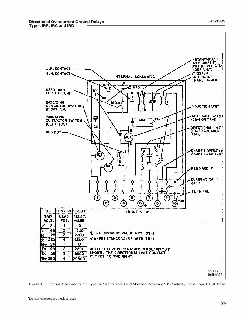
*Sub 29654A57
Figure 10: Internal Schematic of the Type IRP Relay, with Field Modified Reversed “D” Contacts, in the Type FT-31 Case.
25*Denotes change since previous issue
41-133S Directional Overcurrent Ground RelaysTypes IRP, IRC and IRD
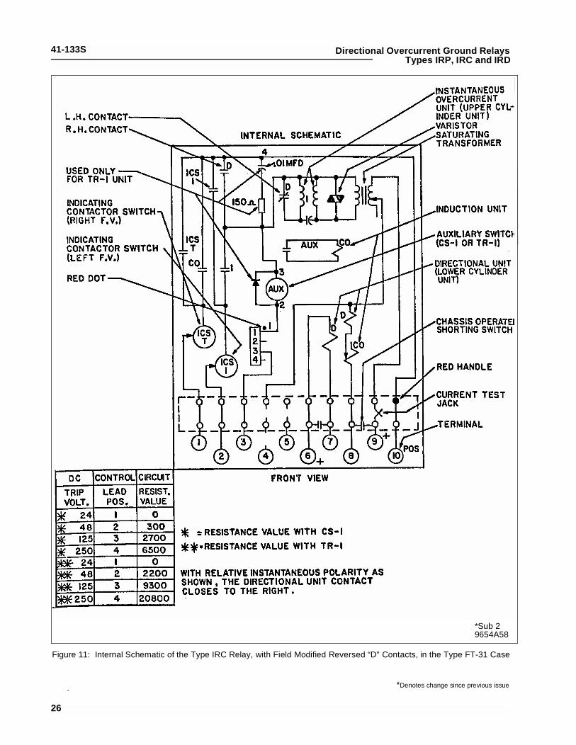
*Sub 29654A58
Figure 11: Internal Schematic of the Type IRC Relay, with Field Modified Reversed “D” Contacts, in the Type FT-31 Case
26
. *Denotes change since previous issue

41-133SDirectional Overcurrent Ground RelaysTypes IRP, IRC and IRD
*Sub 29654A56
Figure 12: Internal Schematic of the Type IRD Relay, with Field Modified Reversed “D” Contacts, in the Type FT-41 Case
27
*Denotes change since previous issue

41-133S
28
Directional Overcurrent Ground RelaysTypes IRP, IRC and IRD
Sub
528
9B50
6
Fig
ure
13:
Ext
erna
l Sch
emat
ic o
f the
IRP
Rel
ay fo
r G
roun
d F
ault
Pro
tect
ion

41-133SDirectional Overcurrent Ground RelaysTypes IRP, IRC and IRD
Sub
428
9B50
7
Fig
ure
14:
Ext
erna
l Sch
emat
ic o
f the
IRC
Rel
ay fo
r G
roun
d F
ault
Pro
tect
ion
29

41-133S
30
Directional Overcurrent Ground RelaysTypes IRP, IRC and IRD
Sub
428
9B50
8
Fig
ure
15:
Ext
erna
l Sch
emat
ic o
f the
IRD
Rel
ay fo
r G
roun
d F
ault
Pro
tect
ion.

41-133SDirectional Overcurrent Ground RelaysTypes IRP, IRC and IRD
*Sub 1619584
Figure 16: Typical Time Curves of the Time-Overcurrent Unit of the Short Time (2) Relays
31
*Denotes change since previous issue

41-133S Directional Overcurrent Ground RelaysTypes IRP, IRC and IRD
Sub 2418245
Figure 17: Typical Time Curves of the Time-Overcurrent Unit of the Long Time (5) Relays
32
41-133SDirectional Overcurrent Ground RelaysTypes IRP, IRC and IRD
*Sub 3 418246
Figure 18: Typical Time Curve of the Time-Overcurrent Unit of the Definite Time (6) Relays
33
*Denotes change since previous issue

41-133S Directional Overcurrent Ground RelaysTypes IRP, IRC and IRD
*Sub 3418247
Figure 19: Typical Time Curve of the Time-Overcurrent Unit of the Definite Time (7) Relays.*Denotes change since previous issue
34

41-133SDirectional Overcurrent Ground RelaysTypes IRP, IRC and IRD
Sub 3 418248
Figure 20: Typical Time Curve of the Time-Overcurrent Unit of the Definite Time (8) Relays.
35
41-133S Directional Overcurrent Ground RelaysTypes IRP, IRC and IRD
Sub 2 418249
Figure 21: Typical Time Curve of the Time-Overcurrent Unit of the Definite Time (9) Relays.
36

41-133SDirectional Overcurrent Ground RelaysTypes IRP, IRC and IRD
Sub 2288B655
Figure 22: Typical Time Curve of the Time-Overcurrent Unit of the Definite Time (11) Relays.
37

41-133S Directional Overcurrent Ground RelaysTypes IRP, IRC and IRD
*Sub 7538108
Figure 2 3 :Typical Operating Times For The Directional Unit
Sub 2538109
Figure 24: Typical Operating Times For the Instantaneous Overcurrent Unit
38
*Denotes change since previous issue
41-133SDirectional Overcurrent Ground RelaysTypes IRP, IRC and IRD
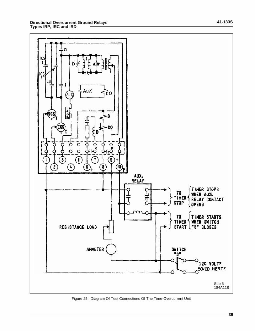
Sub 5184A118
Figure 25: Diagram Of Test Connections Of The Time-Overcurrent Unit
39

41-133S Directional Overcurrent Ground RelaysTypes IRP, IRC and IRD
Sub 4
184A316
Figure 2 6 :Selection of Proper Voltage Tap for Auxiliary Switch Operation
Sub 11518B95
Figure 2 7 :Test Connections
40

41-133S
41
Directional Overcurrent Ground RelaysTypes IRP, IRC and IRD
NOTES


ABB Inc.4300 Coral Ridge DriveCoral Springs, Florida 33065Telephone: +1 954-752-6700Fax: +1 954-345-5329www.abb.com/substation automation
IL 4
1-13
3 - R
evis
ion
S
ABB