Embed Size (px)
Citation preview

Issue 0 TIL – Eng – Spec – 088 Typhoon VMS OM
NOTE
The VMS camera uses lasers which can be harmful to the human eye. It is imperative that users adhere to the safety procedures within this manual.
Supplied by
Typhoon VMS Camera
Operator Manual
For the latest manual revision always visit “www.tritech.co.uk”
The electronic version of this document is the controlled copy. Therefore all printed versions of this document are uncontrolled.
Please read this manual carefully before setting-up and using your unit
LASER RADIATION DO NOT STARE INTO BEAM OR VIEW
DIRECTLY WITH OPTICAL INSTRUMENTS CLASS 3R LASER PRODUCT

F063.1
COPYRIGHT
© Tritech International Ltd
The copyright in this document is the property of Tritech International Limited. The document is supplied by Tritech International Limited on the understanding that it may not be copied, used, or disclosed to others except as authorised in writing by Tritech International Limited. Tritech International Limited reserved the right to change, modify and update designs and specifications as part of their ongoing product development programme.

Tritech International Ltd Typhoon VMS OM
Issue 0 TIL – Eng – Spec – 088 Page 4 of 40
Table of Contents
HANDLING OF ELECTROSTATIC-SENSITIVE DEVICES................................................ 6 Statutory Compliances .......................................................................................................................8
Compliance Notice – CE Mark ......................................................................................................8 Waste Electrical and Electronic Equipment Directive (2002/96/EC - WEEE).................................8
Safety Statements................................................................................................................................8 TECHNICAL SUPPORT...................................................................................................... 9
INTRODUCTION ............................................................................................................... 10
GENERAL INFORMATION............................................................................................... 11 Specifications....................................................................................................................................11 Damage in Shipment ........................................................................................................................11 Repairs ..............................................................................................................................................11 OPERATING CONDITIONS.............................................................................................. 11
SETTING UP PROCEDURES........................................................................................... 12 Power supply.....................................................................................................................................12 Long line amplifier...........................................................................................................................12 Analogue Control .............................................................................................................................12 RS232C Control Commands ............................................................................................................13 DISASSEMBLY PROCEDURES ...................................................................................... 17
PARTS LIST...................................................................................................................... 17
TRITECH VISUAL MEASUREMENT SYSTEM (VMS)..................................................... 19 Software Introduction ......................................................................................................................19 VMS SOFTWARE INSTALLATION.................................................................................. 20
VMS SCREEN LAYOUT AND CONTROLS ..................................................................... 21 Main Menu .......................................................................................................................................21 Main Toolbar....................................................................................................................................22 Measurements Toolbar ....................................................................................................................23 CAPTURING IMAGES FROM THE VMS CAMERA......................................................... 25 Capture Menu...................................................................................................................................25 Capturing Images.............................................................................................................................26 Recording to AVI..............................................................................................................................27 VMS CAMERA CONTROLS ............................................................................................. 28
OPENING AN IMAGE / AVI FILE ..................................................................................... 28 Opening an Image File ....................................................................................................................29 Opening an AVI File........................................................................................................................29

Tritech International Ltd Typhoon VMS OM
Issue 0 TIL – Eng – Spec – 088 Page 5 of 40
PROCESSING AN IMAGE................................................................................................ 31 Image Menu......................................................................................................................................31 CALIBRATING AN IMAGE............................................................................................... 33
MEASURING OBJECTS ON AN IMAGE ......................................................................... 34 Measurements Toolbar ....................................................................................................................34 SAVING AN IMAGE.......................................................................................................... 38 Save Image as TIFF.........................................................................................................................38 Save Image as PDF ..........................................................................................................................38 APPENDIX 1 PRODUCT SPECIFICATION.................................................................. 39
APPENDIX 2 TYPHOON CAMERA PIN CONFIGURATION........................................ 40

Tritech International Ltd Typhoon VMS OM
Issue 0 TIL – Eng – Spec – 088 Page 6 of 40
Handling of Electrostatic-Sensitive Devices
ATTENTION
Observe Precautions For Handling Electrostatic Sensitive Devices
Caution: Certain semiconductor devices used in the equipment are liable to damage due to static voltages. Observe the following precautions when handling these devices in their unterminated state, or sub-units containing these devices:
• Persons removing sub-units from any equipment using electrostatic sensitive devices must be earthed by a wrist strap via a 1MΩ resistor to a suitable discharge reference point within the equipment.
• Soldering irons used during any repairs must be low voltage types with earthed tips and isolated from the Mains voltage by a double insulated transformer. Care should be taken soldering any point that may have a charge stored.
• Outer clothing worn must be unable to generate static charges.
• Printed Circuit Boards (PCBs) fitted with electrostatic sensitive devices must be stored and transported in appropriate anti-static bags/containers.
F110.1
Tritech International Ltd Typhoon VMS OM
Issue 0 TIL – Eng – Spec – 088 Page 7 of 40
Warranty Statement
Tritech International Limited herein after referred to as TIL TIL warrants that at the time of shipment all products shall be free from defects in material and workmanship and suitable for the purpose specified in the product literature. The unit/system warranty commences immediately from the date of customer acceptance and runs for a period of 365 days. Customer acceptance will always be deemed to have occurred within 72 hours of delivery. Note: Any customer acceptance testing (if applicable) must be performed at either TIL premises or at one of their approved distributors unless mutually agreed in writing prior to despatch. Conditions: These include, but are not limited to, the following: 1 The warranty is only deemed to be valid if the equipment was sold through TIL or one of its approved distributors. 2 The equipment must have been installed and commissioned in strict accordance with approved technical
standards and specifications and for the purpose that the system was designed. 3 The warranty is not transferable, except or as applies to Purchaser first then to client. 4 TIL must be notified immediately (in writing) of any suspected defect and if advised by TIL, the equipment subject
to the defect shall be returned by the customer to TIL, via a suitable mode of transportation and shall be freight paid.
5 The warranty does not apply to defects that have been caused by failure to follow the recommended installation or
maintenance procedures. Or defects resulting from normal wear & tear, incorrect operation, fire, water ingress, lightning damage or fluctuations in vehicles supply voltages, or from any other circumstances that may arise after delivery that is out with the control of TIL. (Note: The warranty does not apply in the event where a defect has been caused by isolation incompatibilities.)
6 The warranty does not cover the transportation of personnel and per diem allowances relating to any repair or
replacement. 7 The warranty does not cover any direct, indirect, punitive, special consequential damages or any damages
whatsoever arising out of or connected with misuse of this product. 8 Any equipment or parts returned under warranty provisions will be returned to the customer freight prepaid by TIL 9 The warranty shall become invalid if the customer attempts to repair or modify the equipment without appropriate
written authority being first received from TIL. 10 TIL retains the sole right to accept or reject any warranty claim. 11 Each product is carefully examined and checked before it is shipped. It should therefore be visually and
operationally checked as soon as it is received. If it is damaged in anyway, a claim should be filed with the courier and TIL notified of the damage.
Note: TIL reserve the right to change specifications at any time without notice and without any obligation to incorporate new features in instruments previously sold. Note: If the instrument is not covered by warranty, or if it is determined that the fault is caused by misuse, repair will be billed to the customer, and an estimate submitted for customer approval before the commencement of repairs.
F167.1
Tritech International Ltd Typhoon VMS OM
Issue 0 TIL – Eng – Spec – 088 Page 8 of 40
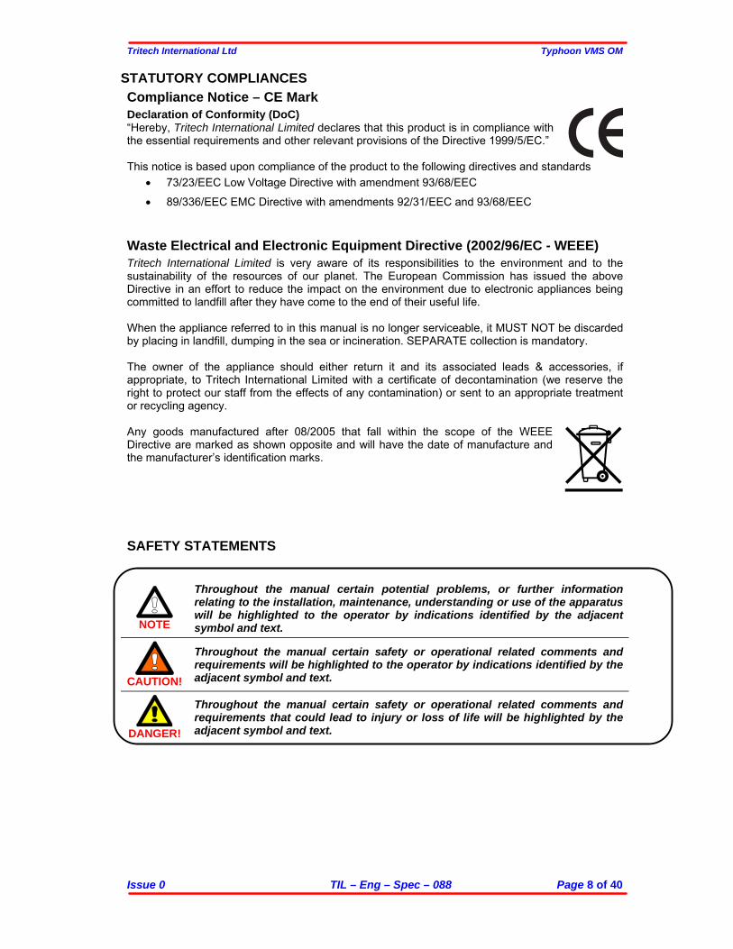
STATUTORY COMPLIANCES Compliance Notice – CE Mark Declaration of Conformity (DoC) “Hereby, Tritech International Limited declares that this product is in compliance with the essential requirements and other relevant provisions of the Directive 1999/5/EC.” This notice is based upon compliance of the product to the following directives and standards
• 73/23/EEC Low Voltage Directive with amendment 93/68/EEC
• 89/336/EEC EMC Directive with amendments 92/31/EEC and 93/68/EEC Waste Electrical and Electronic Equipment Directive (2002/96/EC - WEEE) Tritech International Limited is very aware of its responsibilities to the environment and to the sustainability of the resources of our planet. The European Commission has issued the above Directive in an effort to reduce the impact on the environment due to electronic appliances being committed to landfill after they have come to the end of their useful life. When the appliance referred to in this manual is no longer serviceable, it MUST NOT be discarded by placing in landfill, dumping in the sea or incineration. SEPARATE collection is mandatory. The owner of the appliance should either return it and its associated leads & accessories, if appropriate, to Tritech International Limited with a certificate of decontamination (we reserve the right to protect our staff from the effects of any contamination) or sent to an appropriate treatment or recycling agency. Any goods manufactured after 08/2005 that fall within the scope of the WEEE Directive are marked as shown opposite and will have the date of manufacture and the manufacturer’s identification marks.
SAFETY STATEMENTS
NOTE
Throughout the manual certain potential problems, or further information relating to the installation, maintenance, understanding or use of the apparatus will be highlighted to the operator by indications identified by the adjacent symbol and text.
CAUTION!
Throughout the manual certain safety or operational related comments and requirements will be highlighted to the operator by indications identified by the adjacent symbol and text.
DANGER!
Throughout the manual certain safety or operational related comments and requirements that could lead to injury or loss of life will be highlighted by the adjacent symbol and text.

Tritech International Ltd Typhoon VMS OM
Issue 0 TIL – Eng – Spec – 088 Page 9 of 40
Technical Support
Contact your local agent or Tritech International Ltd
Tritech International Ltd. Peregrine Road, Westhill Business Park, Westhill, Aberdeen, AB32 6JL, UK
Telephone ++44 (0)1224 744111 Fax ++44 (0)1224 741771
Email [email protected] Web www.tritech.co.uk
An out-of-hours emergency number is available by
calling the above telephone number If you have cause to use our Technical Support service, please ensure that you have the following details at hand prior to calling:
• System Serial Number (if applicable) • Fault Description • Any remedial action implemented
Due to the expansion of equipment capabilities and the fact that new sub-modules are continually being introduced, this manual cannot detail every aspect of the operation. The name of the organisation which purchased this system is held on record at Tritech International Ltd. Details of new software and hardware packages will be announced at regular intervals. Depending on the module, free upgrades will be offered in keeping with our policy of maintaining the highest levels of customer support. Tritech International Ltd can only undertake to provide software support for systems loaded with Operating System and Tritech Seanet software in accordance with the instructions given in the System Re-installation section of this manual. It is the customers responsibility to ensure the compatibility of any other package that they may choose to load unless with the prior consent of Tritech.
Tritech International Ltd Typhoon VMS OM
Issue 0 TIL – Eng – Spec – 088 Page 10 of 40
INTRODUCTION The VMS camera uses 5 lasers to project a reference frame of laser illuminated spots onto the scene viewed by the camera. This allows the operator to make both a visual assessment of target size from the real time video and also allow measurements from still images using a special PC image processing package supplied with the camera. To take advantage of the measurement facility the user will require a PC fitted with a video capture card. In the heart of the VMS lies the highly successful Tritech TYPHOON colour zoom camera. This incorporates the latest innovations in CCD sensor technology enhanced by intelligent fuzzy digital signal processing control logic to adjust the shutter speed and white balance to maximise the low light working capabilities of the module. A switch mode power supply board provides all the necessary voltages for the camera module. The module is controlled internally by RS232 providing full adjustment of all the camera functions. In addition external voltage controls are provided for focus and zoom. A 3 stage line driver is available to compensate for cable attenuation of the video signal. The camera module is protected from damage in the event of an accidental misconnection. A water corrected port is fitted to optimise the picture quality. The overall package provides an extremely robust unit for use in harsh environments.

Tritech International Ltd Typhoon VMS OM
Issue 0 TIL – Eng – Spec – 088 Page 11 of 40
GENERAL INFORMATION
SPECIFICATIONS The company reserves the right to change specifications at any time without notice and without any obligation to incorporate new features in instruments previously sold.
DAMAGE IN SHIPMENT The company's instrument is carefully examined and checked before it is shipped. It should be visually and operationally checked as soon as it is received. If it is damaged in any way, a claim should be filed with the carrier. New or repaired instruments damaged in transit should not be returned to the manufacturer without first obtaining specific shipping instructions.
REPAIRS Should any fault develop, the company or its appointed service agent must be notified immediately giving full details of the difficulty. Include in the notification the model number and serial number of the affected instrument. On receipt of this information the company, or its service agent, will send service details or shipping instructions. Upon receipt of shipping instructions, the instrument must be forwarded, carriage pre-paid, and the Company or its service agents at their premises will make repairs. If the instrument is not covered by warranty, or if it is determined that the fault is caused by misuse, repair will be billed to the customer, and an estimate submitted for customer approval before the commencement of repairs.
OPERATING CONDITIONS The camera is compatible with any video recorder or monitor working with the PAL standard. (NTSC units are also available). A PC fitted with an appropriate video frame capture card will be required in order to post process images using the scaling software provided.
NOTE
The capture card must maintain a 3 by 4 bit aspect ratio and have as high a resolution as is practicable.
The camera should not be used out of the limit conditions specified in this manual. For any special requirement please contact TRITECH INTERNATIONAL LTD.
NOTE
If the unit is fitted with the Tritech underwater connector, before attaching the connector to the camera ensure that the O-ring is in position, clean and lightly smeared with silicon grease.
NOTE
The power supply is polarised. Please ensure that the correct polarity is used before switching on the unit.
An internal jumper and a small potentiometer are fitted on the Long Line Driver board to give up to 3 stages of boost to the video signal as required (LLA PCB optional). Greater accuracy will be obtained by the measurement software if:- a) The distance to target is short (typically 1m is good) b) The zoom is set so that the laser pattern occupies a large part of the screen (typically 60%) c) The target area is flat and not inclined too severely to the normal to the camera axis

Tritech International Ltd Typhoon VMS OM
Issue 0 TIL – Eng – Spec – 088 Page 12 of 40
SETTING UP PROCEDURES
POWER SUPPLY
CAUTION!
The power supply output is controlled through a potentiometer, VR1, fitted on the topside of the PSU/Mother board. It is set at the factory and does not require any further adjustment. The camera module voltage should not be any more than 9.5v as an absolute maximum.
LONG LINE AMPLIFIER A Long Line Amplifier (LLA) board is fitted as standard to J3 on the Power Supply Board. The header J2 on the LLA board has position S1 (unity gain) fitted with a shorting link. The same effect can be obtained by removing the LLA and fitting the shorting link to J6 (Amp Bypass) on the Power Supply Board (PSU). In order to alter the position of this jumper, it is necessary to loosen the support rails to gain access to this board. This is not recommended (because of possible upset to the calibration as a whole) and if possible, the amplifier gain setting should be specified at time of purchase. The three possible positions to set the LLA compensation circuits are:- Position S1 (pins 5 to 6) unity gain Position S2 (pins 3 to 4) high frequency boost plus DC gain 2 Position S3 (pins 1 to 2) high frequency and DC boost gain variable using VR1
ANALOGUE CONTROL This option is available through the Camera Control Board (CCB) and is set at time of purchase. The control of the camera functions (Zoom & Focus) can be by a single wire with an applied bi-polar signal (+, 0, -) with respect to (WRT) 0v, or dual wire by reversing the polarity applied on the wires. As factory set the line signal level (analogue control) is set for operation between 12v to 24v WRT 0v, and –12 to –24v WRT 0v. Laser on/off is controlled through pin 6 J1. +12v to 24v on pin 6 sets the lasers on. 0v or not connected sets the lasers off.
View of LLA Board Shorting Link
View of J6 (Amp Bypass) on PSU

Tritech International Ltd Typhoon VMS OM
Issue 0 TIL – Eng – Spec – 088 Page 13 of 39
RS232C CONTROL COMMANDS (For software Version 1.00 Onwards) The following conditions need to be met in order to achieve RS232 control… On the PSU PCB (ST Part# 3606): 0Ω links R4 and R5 should NOT be fitted 0Ω links R6 and R7 should be fitted The position of Jumpers JP1 and JP2 are of no relevance when camera is fitted with PLUG BOARD (ST Part#4570). On the Control PCB (ST Part# 3604): 0Ω links R35, R38, R40 and R42 should be fitted 0Ω links R36, R37, R39 and R41 should NOT be fitted. Communications Protocol Notes: All commands should be sent using upper case characters with ASCII encoding applied. All commands, unless otherwise specified, will only apply to the camera when it is addressed. Data to the camera requires 9600 baud, 8 data bits, no parity and no handshaking and should use ASCII coding. Data to the Camera Control should be preceded by the synchronisation character “%”, and confirmed with a <CR><LF> character pair to start command processing Data from the Camera Control will be preceded by a “:” character and followed by a <CR><LF> character pair. Communication or system errors will only be reported if the camera is enabled and will start with the “:E” symbols. See errors section for further details. [Commands highlighted with a blue background have not yet been functionally added] System Commands Command
Alive
Syntax: “>?” Returns: “OK” Variables: None Description: Allows the controlling unit to test to see if the addressed camera module is alive.
This function is useful for testing if a Camera is using its AUX RS232 – no response – or Main RS232 when it should reply.
Command Dump Data Buffer Syntax: “>DD” Returns: “>DD<space><characters on buffer in binary><CR><LF>” Variables: None Description: Dumps out the Data Buffer Command Reset Syntax: “>Q” Returns: Nothing Variables: None Description: Performs a software Reset Command Version Syntax: “>V” Returns: “V<x.yy>” Variables: <x> and <yy> are ASCII characters representing the major and minor versions of
the software Description: Allows the version of the cameras software to be checked. The returned string
contains a single digit <x> for the major version, and two digits <yy> for the sub version. A typical response may be “V1.00”.

Tritech International Ltd Typhoon VMS OM
Issue 0 TIL – Eng – Spec – 088 Page 14 of 39
Camera Control Commands Command Camera Disable Syntax: “CD<x>” Returns: Nothing Variables: <x> is a single nibble (char 0-9, A-F) specifying the address of the camera Description: This command deactivates the specified cameras command decoding until the
camera is reactivated with a “Camera Enable” (CE) command. Command Camera Enable Syntax: “CE<x>” Returns: “>” Variables: <x> is a single nibble (char 0-9, A-F) specifying the address of the camera Description: This command enables the addressed camera’s command decoding until the
Camera Disable command (CD) is sent. This then allows several cameras to interpret the same instructions. When the instruction is successfully received it will return a “>” character.
Command Camera Reset Syntax: “CR” Returns: Nothing Variables: None Description: Issuing a Camera Reset, returns the Camera to the default set of controls for
Zoom, Focus, Iris etc. Focus Command Focus Auto Syntax: “FA” Returns: Nothing Variables: None Description: Sets the focus mode to automatic, disabling use of the Focus Near, Far and Stop
commands. Command Focus Far (Manual Focus Mode Only) Syntax: “FF” Returns: Nothing Variables: None Description: Sets the “focus far” operation. Manual focus mode is selected with the “FM”
command. Command Focus Manual Syntax: “FM” Returns: Nothing Variables: None Description: Sets the focus mode to manual, allowing use of the Focus Near, Far and Stop
commands. Command Focus Near (Manual Focus Mode Only) Syntax: “FN” Returns: Nothing Variables: None Description: Sets the “focus near” operation. Manual focus mode is selected with the “FM”
command.

Tritech International Ltd Typhoon VMS OM
Issue 0 TIL – Eng – Spec – 088 Page 15 of 39
Command Focus Stop (Manual Focus Mode Only) Syntax: “FS” Returns: Nothing Variables: None Description: Stops the current manual focus operation in progress. Zoom Command Zoom Digital – Continuous Syntax: “ZDC<x>” Returns: Nothing Variables: <x> is 0 for off, 1 for on Description: Activates/Deactivates the continuous digital zoom Command Zoom Digital – Instant Syntax: “ZDI<x>” Returns: Nothing Variables: <x> is 0 for off, 1 for on Description: Activates/Deactivates the instant digital zoom Command Read Zoom Position Syntax: “ZPR” Returns: “ZPR<x>” Variables: <x> is an ASCII character (0-9, A-F) representing the current zoom position Description: Returns the current zoom position of the camera Command Set Zoom Position Syntax: “ZPS<x>” Returns: Nothing Variables: <x> is an ASCII character (0-9, A-F) representing the required zoom position Description: Sets the current zoom position of the camera Command Zoom Stop Syntax: “ZS” Returns: Nothing Variables: None Description: Stops the current Zoom operation.
Command Zoom Telephoto (Zoom In) Syntax: “ZT” Returns: Nothing Variables: None Description: Starts the “zoom telephoto” operation, which will continue at the specified zoom
speed, until a “zoom stop” command is issued.
Command Zoom Speed (Velocity) Syntax: “ZV<x>” Returns: Nothing Variables: <x> is a single nibble value representing…
0 = Slow (6.0 seconds) 1 = Normal (3.6 seconds) 2 = Fast (1.9 seconds)
Description: Starts the speed of a wide or Tele-zoom operation.

Tritech International Ltd Typhoon VMS OM
Issue 0 TIL – Eng – Spec – 088 Page 16 of 40
Command Zoom Wide (Zoom Out) Syntax: “ZW” Returns: Nothing Variables: None Description: Starts the “zoom wide” operation, which will continue at the specified zoom
speed, until a “zoom stop” command is issued. Error Messages If a program error occurs, the system will transmit an error code back to the host system. All errors start with the transmission synchronisation character (“:”) and finish with the Carriage Return and Line Feed Characters (<CR><LF>). All error codes start with the prefix character “E” followed by an ASCII-Hex byte containing the error that occurred.
NOTE
When an error occurs it is placed in the transmission buffer, so if any transmission is already in progress the error will not be returned until the previous transmission has completed (i.e. not in real time). The section below details the possible errors that can be returned…
Serial Communications
NOTE
“E00” as an error code is not allowed, as a software error value of 0 is commonly used to indicate no error.
Command UART Decode Error Returns: “E01” Variables: None Description: A hardware UART decoding error has occurred (Framing or Overrun) Command Receive “Main” Buffer Overflow Returns: “E02” Variables: None Description: Receive Command Buffer has overflowed, when the receiver is in MAIN mode Command Receive “Aux” Buffer Overflow Returns: “E03” Variables: None Description: Receive Command Data Buffer has overflowed, when the receiver is in AUX
mode Command Processor Command Incorrect Syntax Returns: “E10” Variables: None Description: The command characters sent are not recognised as commands. The command
processor is reset ready for the next command NB: All characters should be in uppercase

Tritech International Ltd Typhoon VMS OM
Issue 0 TIL – Eng – Spec – 088 Page 17 of 40
Command Invalid Data Length Returns: “E11” Variables: None Description: The <CR><LF> characters have been sent before the required amount of data
has been received. Finish sending the data the send <CR><LF> to execute the command.
Command Data Buffer Full (Of Bytes) Returns: “E12” Variables: None Description: The amount of data sent has filled the data buffer (to defined length in bytes), so
no more data can be received. Sending <CR><LF> will cause the current data and command to be processed.
Command Data Buffer Full (Of Words) Returns: “E13” Variables: None Description: The amount of data sent has filled the data buffer (to defined length in words), so
no more data can be received. Sending <CR><LF> will cause the current data and command to be processed.
DISASSEMBLY PROCEDURES
NOTE
Under no circumstances should the forward part of the camera (within the red housing) be dismantled, this will invalidate the laser calibration.
To access the internal part of the camera, first remove the nylon retaining cord from the connector end-cap end of the camera. Gently pull the connector end-cap from the main body tube, (you may require the aid of a vice with Vee blocks to hold the main body tube). Be aware that the camera module and electronics are attached to the connector end-cap and will slide out of the body tube when the camera is parted. Before re-assembly, inspect the O-ring for integrity, if any doubt, change it. The O-ring should be cleaned and lightly smeared with silicon grease. Reassemble the camera in the reverse order.
PARTS LIST Front housing Port Port O ring BS247-N70 Calibrated laser assembly Front housing O ring BS247-N70 Front housing threaded lock ring Main camera body Rear end plate End plate O ring End plate securing cord Camera module assembly Power Supply Board (PSU) Camera Control Board (CCB) Long Line Amplifier (LLA) Underwater connector Burton 5507-1508

Tritech International Ltd Typhoon VMS OM
Issue 0 TIL – Eng – Spec – 088 Page 18 of 40
ILLUSTRATION OF VMS CAMERA

Tritech International Ltd Typhoon VMS OM
Issue 0 TIL – Eng – Spec – 088 Page 19 of 40
TRITECH VISUAL MEASUREMENT SYSTEM (VMS)
SOFTWARE INTRODUCTION Tritech VMS is a laser scaling system designed to enable high precision and accurate measurements from video footage taken of an underwater object from any perspective and range up to 3 metres. The system combines state of the art laser systems with a high performance colour camera and software interface to minimise the amount of time spent in calculations. The VMS Software GUI will allow for multiple still frames to be grabbed at any time from live or recorded video footage. Once the laser spots have been calibrated for a particular video still, the VMS Software GUI then enables measurements of lengths, areas and perimeters to be taken using the range of measurement tools. Details of these will be presented in the Software sections which follow. During the calibration process, laser spot calibration is made simple with an Automatic Detect button that will drop marker overlays onto each of the 5 laser spots. If necessary, the position of these markers can then be manually adjusted to correct laser spot centre placement before completion of calibration – the human eye will be the best judge of spot centre although the Automatic routine will apply a centre of mass calculation when placing and centring the markers on each laser spot.

Tritech International Ltd Typhoon VMS OM
Issue 0 TIL – Eng – Spec – 088 Page 20 of 40
VMS SOFTWARE INSTALLATION Tritech VMS software is used in conjunction with the Tritech VMS camera to capture and process underwater images providing basic measurements of underwater features and objects. The VMS software installation can be found on the installation CD that is supplied with the system. If the CD becomes damaged or lost, a new installation file can be supplied on CD or by e-mail. Please contact [email protected] and quote the serial number of the VMS camera. The VMS software installation file is named VMS_Setup.exe. Run this executable to install the VMS program onto the PC. A desktop shortcut will also be created, as follows…
During installation, several program files will be installed on the PC… C:\Program Files\VMS\... VMS.exe (Program Executable) VMS.ini (Program Configuration) VMS.hlp (Help File Text) VMS.cnt (Help File Contents) The VMS software can be installed on a PC with or without a video capture card. If it is installed on a PC without a video capture card, then the VMS software will NOT be able to capture images directly from the VMS camera, but can still post-process and calibrate any previously captured image files.

Tritech International Ltd Typhoon VMS OM
Issue 0 TIL – Eng – Spec – 088 Page 21 of 40
VMS SCREEN LAYOUT AND CONTROLS Before using the VMS software, you should take a minute to familiarise yourself with the basic layout and controls available. Double-click on the VMS desktop icon to open the program.
Once opened, the program will appear as follows…
MAIN MENU File ->
Open - Open an image or AVI file. Close - Close an image file. Save Image - Save an image file. Save PDF - Save an image as an Adobe Acrobat PDF file. Save All Frames - Save all the frames in the Frames Window to one image file. Print Preview - View and configure print options before printing an image. Print - Print an image to a specified printer. Print Setup - Configure printer options. Exit - Close the VMS software.

Tritech International Ltd Typhoon VMS OM
Issue 0 TIL – Eng – Spec – 088 Page 22 of 40
Capture ->
- For more information about the Capture menu, see ‘Capturing Images from the VMS Camera’.
Image ->
- For more information about the Image menu, see ‘Processing an Image’. View ->
Zoom In - Zoom in to the image in the main display window. Zoom Out - Zoom out of the image in the main window. Fit On Screen - When selected, ‘Fit On Screen’ will always make the image fit in the main display window when the window is resized. Actual Size - Display the actual size of the image in the main display window.
Help ->
VMS Guide - View the Help guide for the VMS software. About VMS - View the About dialog for the VMS software. See About.
MAIN TOOLBAR
Open an image or AVI file. Close the image file. Save the image file. Save the image file as a PDF. Preview the image file before printing. Print the image file. Configure printer settings. Toggle capture from the VMS camera on/off. Click and drag the left mouse button on main display to scroll image. Zoom in to the image. Zoom out of the image. Fit the image to the main display window. Show the actual size of the image.

Tritech International Ltd Typhoon VMS OM
Issue 0 TIL – Eng – Spec – 088 Page 23 of 40
MEASUREMENTS TOOLBAR For more information on the Measurements Toolbar, see ‘Measuring Objects on an Image’. Navigator Window
The Navigator Window allows a user to navigate around the image when the image size is larger than the size of the main display window. The area highlighted on the Navigator Window is the area of the image currently visible on the main display window. To scroll around the image on the main display window, simply click and hold the left mouse button over the highlighted area of the Navigator Window and drag the mouse to the new position on the image. Zoom Window
The Zoom Window provides the user with a magnified region around the cursor position when over the main display window. The Zoom Window can be very useful when marking laser spot positions during the image calibration procedure.

Tritech International Ltd Typhoon VMS OM
Issue 0 TIL – Eng – Spec – 088 Page 24 of 40
Frames Window
When opening or capturing images, these will be loaded into the Frames Window. The Frames Window provides a useful way to toggle between large numbers of frames or for a user to return to a default image at any time. All frames loaded in the Frames Window can be saved individually or together as one image file. Right click on an image and select ‘Save Frame’ to save the highlighted frame or select ‘Save All Frames’ to save all frames in the Frames Window to one image file. If multiple frames have been saved to one image file using the ‘Save All Frames’ option, then the next time that image file is loaded into the VMS software, all frames will be loaded into the Frames Window and each individual frame can then be processed. Calibration Window
The Calibration Window displays the current calibration status, results and controls for calibrating an image. For more information, see ‘Calibrating an Image’ . Notes Window
The Notes Window provides the user with a method of digitally annotating an image. Any notes taken will be saved along with the image data in the same file. Notes saved with an image will be displayed in the Notes Window when the image is opened again in the VMS software.

Tritech International Ltd Typhoon VMS OM
Issue 0 TIL – Eng – Spec – 088 Page 25 of 40
CAPTURING IMAGES FROM THE VMS CAMERA All settings for capturing images from the VMS camera are available through the ‘Capture’ main menu item. If the ‘Capture’ menu item is disabled, then there is no video capture device available on the PC.
CAPTURE MENU Camera On - Start capturing images from the selected video input device at the selected video format and source settings. Video Input - Select the video input device from the list which has the VMS camera connected. Video Format - Select the format and resolution required for the image. The resolution required for VMS is 640x480 or higher and the selected resolution MUST have a ratio of 4:3. Recommend resolutions are… 640x480, 800x600, 960x720, 1024x768, 1280x960 Higher image resolutions will give more accurate measurement results so we recommend using the highest resolution available from your video capture device. We also recommend capturing in RGB 24-bit format for optimised image processing. Video Source - Select the correct video source for the video input device from the menu. This menu may be disabled if there is only one video source for the device. Configure - ‘Video Input’, ‘Video Format’ and ‘Video Source’ will bring up the appropriate settings specific to the selected video capture device. ‘Video Codec’ lets you to select a compression codec to use when recording AVI files. This may be useful if you wish to keep file size down when recording for a long length of time, but any compression will degrade image quality. We recommend you keep this setting on ‘Full Frames, Uncompressed’ whenever possible. Record AVI - Toggle video capture to AVI on/off. Grab Frame - Capture a frame from the camera. The frame will be added to the Frames window where it can be viewed or saved.
Tritech International Ltd Typhoon VMS OM
Issue 0 TIL – Eng – Spec – 088 Page 26 of 40
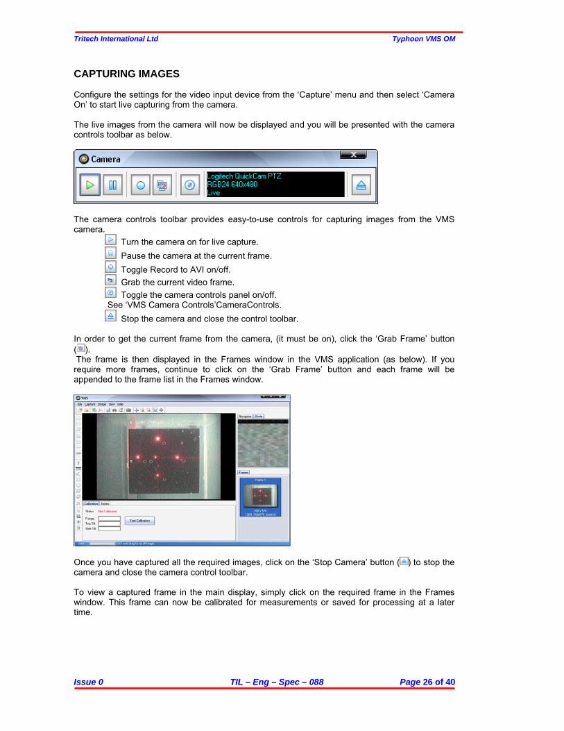
CAPTURING IMAGES Configure the settings for the video input device from the ‘Capture’ menu and then select ‘Camera On’ to start live capturing from the camera. The live images from the camera will now be displayed and you will be presented with the camera controls toolbar as below.
The camera controls toolbar provides easy-to-use controls for capturing images from the VMS camera.
Turn the camera on for live capture. Pause the camera at the current frame. Toggle Record to AVI on/off. Grab the current video frame. Toggle the camera controls panel on/off.
See ‘VMS Camera Controls’CameraControls. Stop the camera and close the control toolbar.
In order to get the current frame from the camera, (it must be on), click the ‘Grab Frame’ button ( ). The frame is then displayed in the Frames window in the VMS application (as below). If you require more frames, continue to click on the ‘Grab Frame’ button and each frame will be appended to the frame list in the Frames window.
Once you have captured all the required images, click on the ‘Stop Camera’ button ( ) to stop the camera and close the camera control toolbar. To view a captured frame in the main display, simply click on the required frame in the Frames window. This frame can now be calibrated for measurements or saved for processing at a later time.

Tritech International Ltd Typhoon VMS OM
Issue 0 TIL – Eng – Spec – 088 Page 27 of 40
To save the current image in the main display, select ‘File’ -> ‘Save Image’ from the menu. If you wish to save the captured frame(s) in the Frames window, RIGHT-CLICK on the image you wish to save and select ‘Save Frame’. If you have more than one frame to save, all frames can be saved together in one image file. This can be done by a RIGHT-CLICK on any image in the Frames window and selecting ‘Save All Frames’.
RECORDING TO AVI From the ‘Capture’ menu select ‘Camera On’ to start live video capture from the camera. Click on the ‘Record to AVI’ button to begin recording the AVI file. In the dialog, select a directory and name for the file and click on the ‘Save’ button.
CAUTION!
The directory you choose to save the AVI file MUST be on a local hard disk (i.e C:\..\..), NOT a drive across a network. Recording across a network is not supported and may cause the VMS software to become unresponsive.
While recording an AVI file, the Record button will be red and the video controls toolbar display will report the AVI file name and how much frames have been recorded to the file.
To stop recording the AVI file, simply click on the ‘Record to AVI’ button again. The Record button should change from red to blue in colour and the video controls toolbar display will report the camera status as ‘Live’.

Tritech International Ltd Typhoon VMS OM
Issue 0 TIL – Eng – Spec – 088 Page 28 of 40
VMS CAMERA CONTROLS The VMS software provides RS-232 controls for a camera configured in RS-232 comms mode. The camera control panel can be accessed from the Camera Toolbar. See ‘Capturing Images from the VMS Camera’ for more information about the Camera Toolbar.
Focus Toggle ‘Auto Focus’ on/off. When the ‘Auto Focus’ function is off, the camera focus can be manually adjusted using the controls. Zoom Use the controls to adjust camera zoom. The speed of the camera zoom can be adjusted between Slow/Normal/Fast. Click on ‘DIG’ to toggle digital zoom on/off. Lights Toggle the cameras lights and lasers on/off. DSS Toggle the cameras Digital Slow Shutter (DSS) on/off. COM This displays the selected serial COM port and status. If the COM port is open then the LED will be green. The COM port can be configured by clicking on the ‘Setup’ button.
OPENING AN IMAGE / AVI FILE The VMS software can open a wide variety of image formats as well as AVI movie files for processing.

Tritech International Ltd Typhoon VMS OM
Issue 0 TIL – Eng – Spec – 088 Page 29 of 40
OPENING AN IMAGE FILE Double-click on the VMS desktop icon to start the program. Select ‘File’ -> ‘Open’ from the main menu or click on the ‘Open File’ button on the main toolbar. Select the image file you wish to open and click on the ‘Open’ button.
The image has now been loaded into the VMS software and is ready for processing and calibration. If you opened an image file which contains multiple frames, then all frames from the file will be loaded into the Frames window and the first frame will be shown on the main display.
OPENING AN AVI FILE Double-click on the VMS desktop icon to start the program. Select ‘File’ -> ‘Open’ from the main menu or click on the ‘Open File’ button on the main toolbar. Select the AVI file you wish to open and click on the ‘Open’ button.

Tritech International Ltd Typhoon VMS OM
Issue 0 TIL – Eng – Spec – 088 Page 30 of 40
At the AVI pre-loader screen, you can play back the image file to find the exact frame(s) you wish to do measurements on. The controls allow you to step forward and backward by a single frame and the current frame number is displayed at the bottom left of the video display.
Once you have found the frame(s) you wish to work with, you can decide to open (a) the current frame or (b) a list of frames. If you decide to open a list of frames then enter the list as follows, 1,2,5-9,12. This example would open frames 1,2,5,6,7,8,9 and 12. Click on the ‘Open’ button to continue.
The frame(s) have now been loaded into the VMS software and are ready for processing and calibration. If you chose to open more than one frame, then all selected frames will be loaded into the Frames window and the first selected frame will be shown in the main display.

Tritech International Ltd Typhoon VMS OM
Issue 0 TIL – Eng – Spec – 088 Page 31 of 40
PROCESSING AN IMAGE The VMS software contains a number of features to enhance an image file before calibration or measurements take place. All image processing features are contained in the ‘Image’ menu and are listed below.
IMAGE MENU Undo Undo the previous image processing action. Undo can remember up to 5 imaging processing actions. If more than 5 image processing actions have taken place, then Undo will only undo the last 5 actions. Adjustments >
Auto Enhance 1 - Auto Enhance 1 performs complex operations on the image to make the image have better contrast and colour.
Auto Enhance 2 - Auto Enhance 2 performs a different set of complex operations on the image to make the image have better contrast and colour.
Hue/Saturation… - Adjust the Hue and saturation value of the image.
Brightness/Contrast… - Adjust the brightness and contrast of the image.
RGB Levels - Adjust the Red, Green and Blue levels of the image.
Gamma Correction… - Gamma correction controls the overall brightness of the image by processing the linear RGB data to compensate for the gamma of the display.
Sharpen… - Adjust the ‘Amplitude’ value to sharpen the edges in the image. The ‘Window
Size’ value adjusts the number of surrounding pixels affected by the ‘Amplitude’ value.
White Balance >
Auto White - Automatically adjusts the image colours by adjusting the white range.
Gray World - Automatically adjusts the image colours by applying the ‘Gray World’ white balance algorithm.
Tritech International Ltd Typhoon VMS OM
Issue 0 TIL – Eng – Spec – 088 Page 32 of 40
Gain Offset - Automatically adjusts the image luminosity by calculating the min and max pixels values and stretching the colours to the maximum allowed value.
Invert - Invert all colours in the image.
Equalize - Equalize the colour histogram of the image.
Greyscale - Convert the image from colour to greyscale.
Filter >
Sharpen - Perform a sharpening filter on the image which places equal emphasis on all neighbouring pixels.
Smooth - Perform a smoothing filter on the image.
Edge - Perform an Edge Detect filter on the image.
Emboss - Perform an Emboss filter on the image.
Bump Mapping… - Apply a bump mapping effect to the current image.
High Pass 1 - Apply a high-pass spatial filter to the image. High-pass filters enhance areas that have high spatial frequencies. They are typically used to emphasize edges and therefore to 'sharpen' images.
High Pass 2 - Apply an alternative high-pass spatial filter to the image.
High Pass 3 - Apply an alternative high-pass spatial filter to the image.
Low Pass 1 - Apply a low-pass spatial filter to the image. Low-pass filters ‘smooth’ the data and makes the resulting image appear less granular, which suppresses image noise.
Low Pass 2 - Apply an alternative low-pass spatial filter to the image.
Custom… - Apply your own custom filter to the image.
Histogram… Adjust the colour histogram of the image. Adjust the min and max levels for Equalization and Threshold by moving the arrows in the corners of the histogram box. This can be useful to remove background colours and locate the laser spots in harsh environments.

Tritech International Ltd Typhoon VMS OM
Issue 0 TIL – Eng – Spec – 088 Page 33 of 40
CALIBRATING AN IMAGE Before any measurements can take place on the image it must be calibrated using the quick and simple procedure below. Run the VMS software and capture or open an image for measurement. Click on the ‘Start Calibration’ button on the Calibration window at the bottom of the VMS software display.
Each laser spot must now be marked IN THE CORRECT ORDER. This can be done manually or automatically.
To manually mark the laser spots… Use the buttons marked P1.to P5. One at a time, mark the laser spots as the layout suggests by clicking on the appropriate button and then clicking on the corresponding laser spot on the image. Use the Zoom window to help you find the laser spot centre. To automatically mark the laser spots… Set the colour of the laser spots by clicking on the ‘Pick Colour’ button and then clicking on a laser spot on the image. Once the laser spot colour has been set click on the ‘Auto Detect’ button. The VMS software will now try to mark the laser spots in the correct order. Please note that this process will take a few moments and may take longer on larger images and images with lots of background noise similar in colour to the laser.
If required, the marker positions can be adjusted by holding down the left mouse button on top of a marker and dragging it to the new position.

Tritech International Ltd Typhoon VMS OM
Issue 0 TIL – Eng – Spec – 088 Page 34 of 40
Once all laser spots have been marked in the correct order, click on the ‘Calibrate’ button to complete the image calibration procedure. The calibration results are now displayed to confirm a successful image calibration.
Once the image has been successfully calibrated, measurements can now be taken.
MEASURING OBJECTS ON AN IMAGE Before any measurements can be taken on an image, it must first be calibrated. Once the image has been successfully calibrated, the Measurements Toolbar (which runs along the left side of the VMS software) becomes active and measurements can then be made.
MEASUREMENTS TOOLBAR Rectangle Selection [ ] Use the Rectangle Selection tool to select a rectangular area of interest. With the area of interest selected, click on the Selection Area and Selection Length buttons to get the area and perimeter of the selection.
Ellipse Selection [ ] Use the Ellipse Selection tool to select a circular area of interest. With the area of interest selected, click on the Selection Area and Selection Length buttons to get the area and perimeter of the selection.

Tritech International Ltd Typhoon VMS OM
Issue 0 TIL – Eng – Spec – 088 Page 35 of 40
Polygon Selection [ ] Use the Polygon Selection tool to select a free-hand area of interest. With the area of interest selected, click on the Selection Area and Selection Length buttons to get the area and perimeter of the selection.
Selection Area [ ] Click on the Selection Area button to display the total area of a rectangle, ellipse or polygon selection. Selection Length [ ] Click on the Selection Length button to display the total perimeter length of a rectangle, ellipse or polygon selection. Drag Length [ ] Use the Drag Length tool to get quick point-to-point distance measurements.
Select Measurement Units [ ] Measurement units available include inches, centimeters and millimeters. Insert Text [ ] Click and drag the left mouse button on the image to insert a text object. The Text Style toolbar will then be displayed.
Set the required text parameters using the Text Style toolbar, click inside the text object and type the required text.

Tritech International Ltd Typhoon VMS OM
Issue 0 TIL – Eng – Spec – 088 Page 36 of 40
Insert Ruler [ ] Use the Insert Ruler tool to click and drag a ruler measurement on the image.
Insert Angle [ ] Use the Insert Angle tool to measure an angle between items of interest on the image. Three left mouse clicks in total are required to insert the angle object.
Insert Rectangle [ ] Use the Insert Rectangle tool to click and drag a rectangular object over an area of interest.
Insert Ellipse [ ] Use the Insert Ellipse tool to click and drag a circular object over an area of interest.
Insert Polygon [ ] Use the Insert Polygon tool to insert a free-hand object over an area of interest. Click the left mouse button to add a new point to the polygon region.

Tritech International Ltd Typhoon VMS OM
Issue 0 TIL – Eng – Spec – 088 Page 37 of 40
Edit Polygon [ ] Use the Edit Polygon tool to add, remove and adjust the points of a polygon object. The points of the polygon are marked in red. To adjust a point, click and hold the left mouse button over a point and drag to the new position. To add a new point, left mouse click on the required position of the polygon (a + symbol should appear to the top right of the cursor). To remove a point, press and hold CTRL and left mouse click on the point to be removed (a – symbol should appear to the top right of the cursor).
Select Colour [ ] Change the colour used to draw the objects. Select Object [ ] Allows the user to select and adjust individual objects on the image. Select All [ ] Select all the objects drawn on the image. Hide All [ ] Hide all the objects drawn on the image. Delete Object [ ] Delete the selected object. If more than one object is selected, then all selected objects will be deleted. Alternatively, press the Delete key on the keyboard to delete objects.

Tritech International Ltd Typhoon VMS OM
Issue 0 TIL – Eng – Spec – 088 Page 38 of 40
SAVING AN IMAGE The VMS software supports saving files to either a TIFF image format or Adobe Acrobat PDF format. To save an image follow the steps bellow.
SAVE IMAGE AS TIFF The VMS software saves image files using the TIFF format. The TIFF image format is designed to hold information about the file as well as the image data. This allows all VMS calibration information and user notes (entered via the Notes window) to be saved along with the image data in one file. Follow the steps below to save an image file as a TIFF. With the image open in the VMS main display, select ‘File’ -> ‘Save Image’ from the main menu or click on the ‘Save Image’ button on the main toolbar. In the dialog, select a directory and name for the file and click on the ‘Save’ button. If you are saving a file which has been calibrated or contains measurements, it may be good practice not to overwrite the original image file. If you are saving a calibrated image, then all calibration information will be saved along with the image data in the same TIFF file. If you have added any notes in the Notes window, then this information will also be saved with the image data in the same TIFF file. If you have placed any measurement objects onto the image, then these measurement objects will be permanently drawn onto the image and cannot be removed. If you have drawn objects onto the image, then it is good practice not to overwrite the original image file.
SAVE IMAGE AS PDF The VMS software allows a user to save the image as an Adobe Acrobat PDF document. When saved as a PDF, the image will not contain any calibration information or user notes and cannot be re-opened in the VMS software. Follow the steps below to save an image file as a PDF. With the image open in the main VMS display, select ‘File’ -> ‘Save PDF’ from the main menu or click on the ‘Save PDF’ button on the main toolbar. In the dialog, select a directory and name for the file and click on the ‘Save’ button.

Tritech International Ltd Typhoon VMS OM
Issue 0 TIL – Eng – Spec – 088 Page 39 of 40
APPENDIX 1 Product Specification

Tritech International Ltd Typhoon VMS OM
Issue 0 TIL – Eng – Spec – 088 Page 40 of 40
APPENDIX 2 Typhoon Camera Pin Configuration