Embed Size (px)
Citation preview
Emerson Network Power. The world leader in business-critical continuity. EmersonNetworkPower.com
AC Power Systems
Connectivity
DC Power Systems
Embedded Power
Integrated Cabinet Solutions
Outside Plant
Precision Cooling
Services
Emerson Network Power and the Emerson Network Power logo are trademarks and service marks of Emerson Electric Co. ©2007 Emerson Electric Co.
A SCO Power Te chnologies50 Hanover Road F lorham Park NE W JERSE Y 07932 USA
800 800 A SCOWWW.A SCO P OWER.CO MA SIA
AUS TRALIA
B R A Z I L
C AN A DA
GERMANY
J A PAN
ME X I CO
SOUTH AFRIC A
SOUTH AMERIC A
UNITED ARAB EMIR ATE S
UNITED KINGDOM
U N I T E D S TAT E S
Publication 3141 R3 © August, 2007 Printed in the U.S.A.
Power Switching & Controls Site Monitoring
Surge & Signal Protection
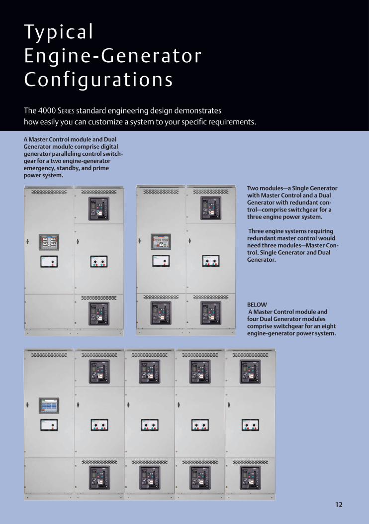
Typical Engine-Generator ConfigurationsThe 4000 Series standard engineering design demonstrates how easily you can customize a system to your specific requirements.
BELOW A Master Control module and four Dual Generator modules comprise switchgear for an eight engine-generator power system.
Two modules—a Single Generator with Master Control and a Dual Generator with redundant con-trol—comprise switchgear for a three engine power system.
Three engine systems requiring redundant master control would need three modules—Master Con-trol, Single Generator and Dual Generator.
A Master Control module and Dual Generator module comprise digital generator paralleling control switch-gear for a two engine-generator emergency, standby, and prime power system.
12
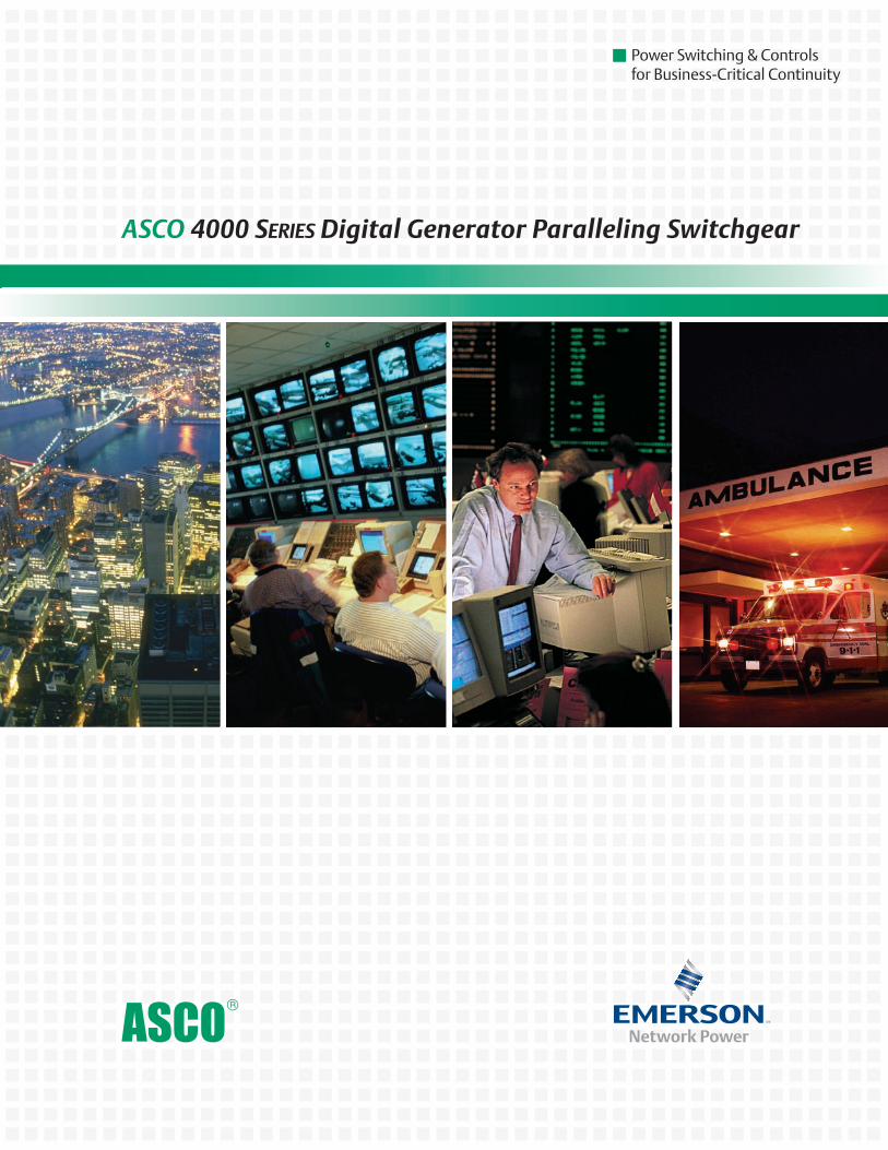
DiSCover The aweSoMe power
of The aSCo 4000 SerieS
DiGiTal GeneraTor parallelinG
ConTrol SwiTChGear
The aSCo 4000 SerieS Digital Generator parallel-ing Control Switchgear is an advanced, multiple-en-gine power control solu-tion that starts, synchro-nizes, parallels, monitors and protects emergency, standby, and prime power systems.
The 4000 power Control System gives you aSCo’s unsurpassed engine control and load management expertise.
You’re in Total Command
parallel up to eight engines and manage up to 64 automatic transfer switches.
Control a power system from easy-to-operate screens at the system, or monitor remotely from a control center or anywhere in the world over the Internet. Monitor your power 24x7x365.
Master Its Power
The 4000 Series Digital Generator Paralleling Control Switchgear is a winning combination of...
The proven and trusted features that have helped make ASCO the world leader in power transfer switching and control...
And cutting-edge, user friendly digital technology.
4000 S e r i e s System Specif ications* If the system is for a
healthcare facility, for ex-ample, can the touch screen quickly access JCAHO1 records and information to help satisfy reporting requirements?
Does it have automatic load shed control? How about a system one-line schematic overview?
The answers are, ‘Yes.’ What are your specific requirements?
Standard featuresLoad demand with operator adjustment of settingsEthernet or RS485 con-nectivity to Building Management SystemTest with loadTest without loadAutomated manual paralleling with graphi-cal synchroscopeAlarmsLCD touch screenAutomatic synchro-nizing and paralleling controls
Optional Accessories
One touch screen per Generator moduleRemote annunciationRedundant master PLCLoad control for up to 64 ATS’s
•
•
•••
•••
•
•••
Electrical operation load bank breakers(EO)Breaker lifting devices (portable or overhead)Spare partsExtended warranty
Controls Touch screen is stan-dard with the Master module; optional with Generator modulesAutomatic synchro-nizing and paralleling controlsControls hardware — Master PLC redundancy — Distributed processing — High speed CANbus
Touch Screen 12 in. color TFT on Mas-ter moduleDisplay on each pair of generators is optionalSystem overview screen with one line schematicReal time clockJCAHO records are avail-able if the generator(s) is/are properly equippedScreens:
Main MenuGenerator One-LineMeteringSystem StatusAlarm Status
•
•
••
•
•
•
•
•
•
••
•—————
ATS StatusDual MeteringkW TrendingMulti-TrendingManual ParallelingLog InEvent Log
System Control
Automatic standbyLoad management controlAutomatic load shed controlController on each gen-erator, optionalRedundant master con-trollers, optionalAutomatic generator load demand controlEmergency stop
Engine-Generator Control
Engine-generator of your choiceAutomatic engine startAdjustable engine cool-down timerAutomatic synchronizerEngine governor con-trol, load sharing, soft loading/unloadingVoltage regulator con-
———————
••
•
•
•
•
•
•
••
••
•
trol VAR/PF sharingAutomated manual paralleling
MeteringVoltage A-B, B-C, C-A (or AN, BN, CN)Current A,B,CFrequencyPower factorkWkVAR
Generator protective relaying
Device 27/59 under/over voltageDevice 81 O/U over/un-der frequencyDevice 15 Automatic synchronizerDevice 32 Reverse powerDevice 40 Loss of excita-tionDevice 25 Synch check
Engine Alarms (if properly equipped)
Low coolant tempera-ture pre-alarmHigh coolant tem-perature pre-alarm and shutdownLow oil pressure pre-alarm and shutdownLow fuel alarmLow engine battery alarm
•
•
•••••
•
•
•
•
•
•
•
•
•
••
Overcrank shutdownOverspeed shutdown
Circuit Breakers Breaker brand of your choiceDrawoutUL 1066 with two-step energy storage100KAIC Rated5 Cycle closingElectrically operated on generators and man-ually operated on dis-tributionAuxilliary and bell alarm contactsTrip unit with LSIA func-tions on generators and LSIG or LSI function on distribution
power Supply Best DC source selector systemPower from 24 VDC en-gine cranking batteriesDC-DC converter
Enclosure and Bus Constucted and labeled to UL1558 is standardUp to 600V 3 phase 4 wire AC system with 100% neutral and (25%) ground bus Main bus amperage up to 10,000 amps
••
•
••
•••
•
•
•
•
•
•
•
•
AS YOu leARN ABOuT
THe 4000 series, iT’S
NATuRAl TO ASk iF iT
CAN SATiSFY THe SPeCiFiC
RequiReMeNTS YOu HAVe
FOR A POWeR CONTROl
SYSTeM.
Silver plated copper busBraced for 100KAICNeMA 1 (3R available)ANSi GrayShipping splits at each section to ease instal-lation
Serial Based Communications
Engine network com-munications Automatic Transfer Switches
Standard for 32 ATSs, optional for 64 ATSsHard-wired start signalsHard-wired load shed relays
Building Management Network
Modbus RTU serial RS 485Modbus TCP Eth-ernet
High reliability, industri-ally hardened redun-dant capability on single pathHigh speed automation network
•••••
•
•
—
—
—
•
—
—
•
•
1. Joint Commission on Accreditation of Healthcare Organizations
* For detailed specifications please request publication 3135
1 13 14
*Dual - Generator Control Section shown with optional touch screen
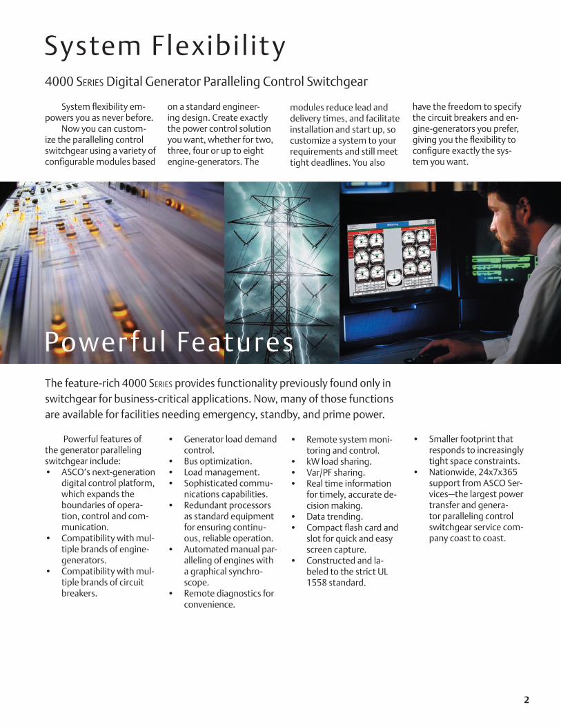
System flexibility em-powers you as never before.
Now you can custom-ize the paralleling control switchgear using a variety of configurable modules based
System Flexibil it y
on a standard engineer-ing design. Create exactly the power control solution you want, whether for two, three, four or up to eight engine-generators. The
Power ful Features
Powerful features of the generator paralleling switchgear include:
ASCO’s next-generation digital control platform, which expands the boundaries of opera-tion, control and com-munication. Compatibility with mul-tiple brands of engine-generators.Compatibility with mul-tiple brands of circuit breakers.
•
•
•
Generator load demand control.Bus optimization.Load management.Sophisticated commu-nications capabilities.Redundant processors as standard equipment for ensuring continu-ous, reliable operation. Automated manual par-alleling of engines with a graphical synchro-scope.Remote diagnostics for convenience.
•
•••
•
•
•
Remote system moni-toring and control.kW load sharing.Var/PF sharing.Real time information for timely, accurate de-cision making.Data trending.Compact flash card and slot for quick and easy screen capture.Constructed and la-beled to the strict UL 1558 standard.
•
•••
••
•
Smaller footprint that responds to increasingly tight space constraints.Nationwide, 24x7x365 support from ASCO Ser-vices—the largest power transfer and genera-tor paralleling control switchgear service com-pany coast to coast.
•
•
The feature-rich 4000 Series provides functionality previously found only in switchgear for business-critical applications. Now, many of those functions are available for facilities needing emergency, standby, and prime power.
4000 Series Digital Generator Paralleling Control Switchgear
modules reduce lead and delivery times, and facilitate installation and start up, so customize a system to your requirements and still meet tight deadlines. You also
have the freedom to specify the circuit breakers and en-gine-generators you prefer, giving you the flexibility to configure exactly the sys-tem you want.
2
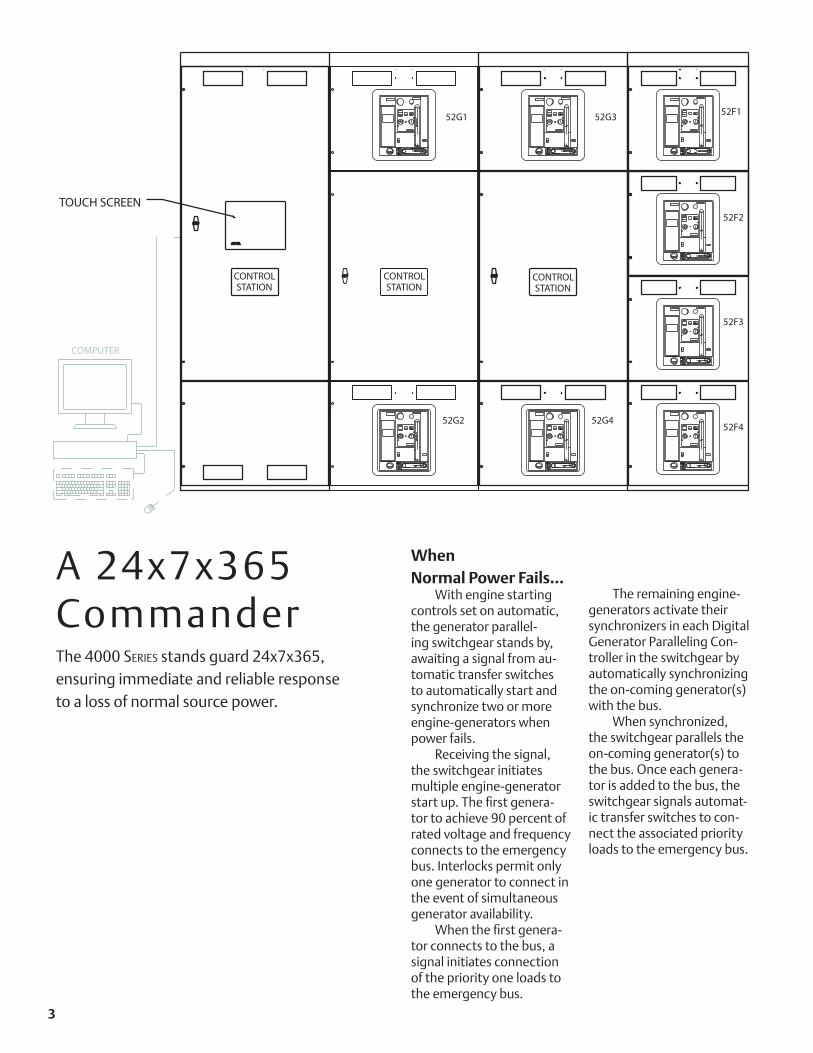
When Normal Power Fails…
With engine starting controls set on automatic, the generator parallel-ing switchgear stands by, awaiting a signal from au-tomatic transfer switches to automatically start and synchronize two or more engine-generators when power fails.
Receiving the signal, the switchgear initiates multiple engine-generator start up. The first genera-tor to achieve 90 percent of rated voltage and frequency connects to the emergency bus. Interlocks permit only one generator to connect in the event of simultaneous generator availability.
When the first genera-tor connects to the bus, a signal initiates connection of the priority one loads to the emergency bus.
The remaining engine- generators activate their synchronizers in each Digital Generator Paralleling Con-troller in the switchgear by automatically synchronizing the on-coming generator(s) with the bus.
When synchronized, the switchgear parallels the on-coming generator(s) to the bus. Once each genera-tor is added to the bus, the switchgear signals automat-ic transfer switches to con-nect the associated priority loads to the emergency bus.
A 24x7x365 CommanderThe 4000 Series stands guard 24x7x365, ensuring immediate and reliable response to a loss of normal source power.
COMPUTER
STATIONCONTROL
TOUCH SCREEN
52G2
52G1
52G4
52G3
52F4
52F3
52F1
52F2
STATIONCONTROL
STATIONCONTROL
52F3
3

The next-generation technology combines a controller, touch screen operator interface, networking and I/O with programmable software for graphics and logic.
The unit provides true, integrated control of each engine-generator and simplifies power system operation, control and communication.
The controller automatically operates the system to efficiently add loads to the bus. It also ensures that engine-generators assume the highest priority loads first and manages the number of engine-generators needed to power those loads.
Operation is immediate and reliable, giving you peace of mind. Operational parameters can be set up through the touch screen, without a laptop computer.
The system controller provides power monitoring, relay protection, generator paralleling and intelligent load management functions for the emergency prime power and/or standby power system applications.
S implif y Power System ManagementAdvanced Digital Control Provides Reliability, Flexibility
The 4000 Series Generator Paralleling Switchgear debuts ASCO’s next-generation digital paralleling controller. The unit offers the reliability of an industrial programmable logic controller.
System Highlights
Dual three phase 600 Vac inputs and dual three phase 0-5 amp inputs, with true RMS sensing and phase angle relationshipsPeer-to-peer network-ing between units (CAN, Ethernet)Manual paralleling using graphical push buttons and synchroscope via master touch screen
•
•
•
The capabilities of the digital paralleling controller enable you to tailor the breadth and ease of control you want in your onsite power system.
The controller commu-nicates through an Ether-net connection with a range of building networks using most major media and protocols. Seamlessly inte-grating with your existing communications infrastruc-ture eliminates the expense of extra hardware and software, and facilitates start up.
Manual paralleling (optional) using physi-cal provisions mounted on a master door Graphical trending of the generatorsPower metering of the three phase sourcesThree phase protection on the generatorDual remote diagnos-tics with reciprocal back up—one uses an industrial-grade analog modem, the other an Ethernet IP connection
•
•
•
•
•
Optional hot-backup processor capabilityCompact flash slot and card for capturing screen displays and data for remote analysisFlexible third-party communication con-nectivityA wide selection of system optional acces-soriesChoice of two cur-rent breaker brands (Square - D or Siemens)
•
•
•
•
•
This elevation (opposite page) and one-line sche- matic show a typical, four engine-generator paralleling control switchgear configura-tion. Available distribution modules and remote control-ler can be integrated into the switchgear.
If a Generator Fails…If a generator fails while
operating in the automatic mode, the 4000 Series dis-connects it from the bus and shuts it down. The switch-gear signals the associated priority loads to shed.
The switchgear acti-vates audible and visual alarms to indicate the condi-tion. A control push-button permits operators to over-ride the load shed circuits.
If a bus overloads, causing an under-frequency condition, the switchgear automatically resets the manual override to prevent sustained bus overloading.
Managing Load Demand…
When the switchgear is set on load demand opera-tion, it automatically man-ages the number of genera-tors online, based on total power requirements.
The switchgear com-pares the actual load of the total generator bus to the running reserve capacity of total generators.
Depending on pre-de-termined kW set-points and time delays, the switchgear starts, synchronizes and soft loads generators on line. It also takes low priority en-gine-generator(s) off-line. It will soft unload the engine, open the circuit breaker and initiate the cool down sequence.
Restoring To Normal Source…
When the automatic transfer switches signal that commercial power has been restored and the transfer switches have retransferred loads to the normal source, the switchgear simultane-ously opens the generator circuit breakers.
The engines then run for a no-load, user-defined cool-down period. The con-trol system stands poised for the next power failure or regular system test.
If a bus under frequency or kW overload occurs while engine(s) are cooling down, the running units actively synchronize and parallel to the bus.
If engines are not run-ning, the control system im-mediately gives the rested engine(s) start signals and parallels them to the bus.
If a bus under frequency or kW overload occurs while generators are on line, the associated loads are shed, the condition is alarmed and a manual reset is required.
52G1
G1
G252
G2
52G3
G3 G4
G452
N E EN N EATS ATS ATS
DISTRIBUTION PANELS
52F4
52F3
F152
F252
N E ATS
UTILITY
6 9 4
Local area networks and remote networks are supported with either single or multiple points of access.
Web-enabled communica-tions allow access to your power system from any-where in the world.
ASCO communications products make it easy to monitor your prime power, emergency and/or standby power distribution systems onsite or remotely.
N e t w o r k Y o u r E m e r g e n c y Power System*
Ethernet
ASCO 5220Power Manager
Utility Power
ASCO Series 300Power Transfer
Switch
BuildingManagement
System
or RS485 MODBUS
ASCO 4000 SeriesPower Transfer
Switch
RS485
ASCO 5110Serial Module
(72A)
ASCO 5110Serial Module
(72A)
Engine-Generator Engine-Generator
ASCO 7000 Series
Power Control System
and/or RS485 MODBUS
Modbus TCP/IP
PCS Remote Annunciator
Fiber Optic EthernetPCSRemote Annunciator
or RS485
RS485 MODBUS RS485 MODBUS
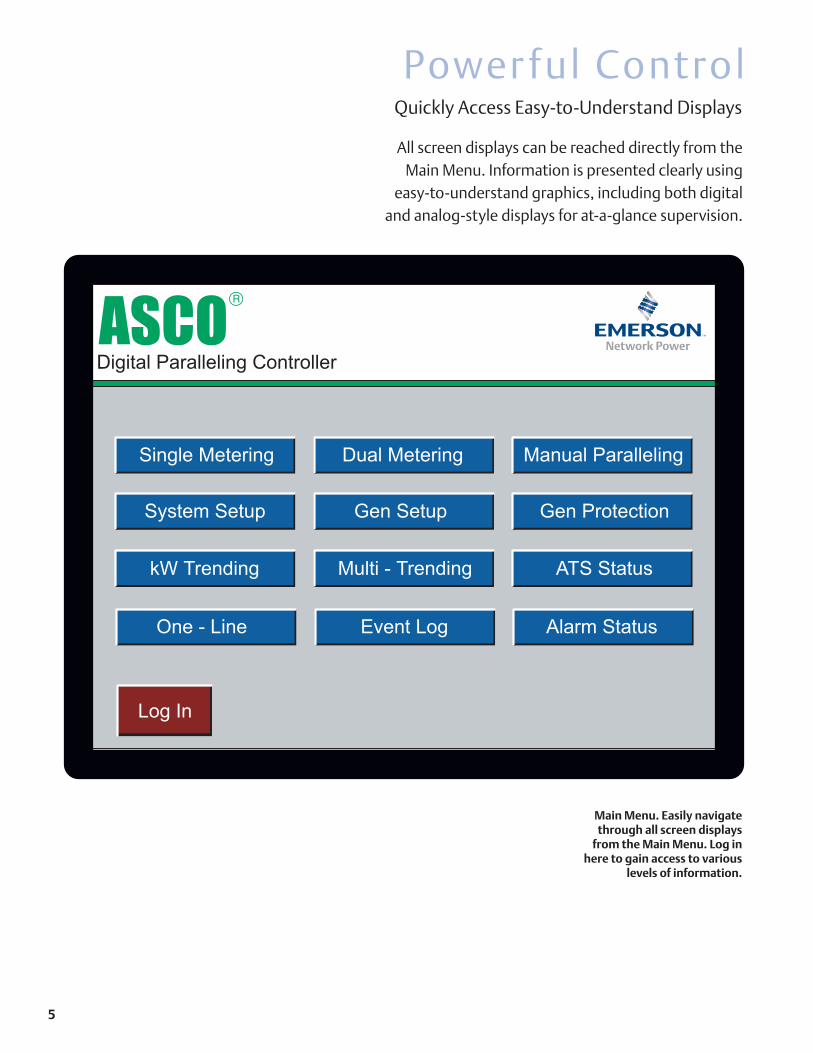
Power ful Control
Main Menu. Easily navigate through all screen displays
from the Main Menu. Log in here to gain access to various
levels of information.
All screen displays can be reached directly from the Main Menu. Information is presented clearly using
easy-to-understand graphics, including both digital and analog-style displays for at-a-glance supervision.
Quickly Access Easy-to-Understand Displays
ASCO
Digital Paralleling Controller
Single Metering Dual Metering Manual Paralleling
System Setup Gen Setup Gen Protection
kW Trending Multi - Trending ATS Status
One - Line Event Log Alarm Status
Log In
12:12 PM
Logged In-2 kW Trending
400
0
0
K
W
A
T
T
S
Time (sec) 425.04
STOPGen 1 - Red
Gen 2 - Yellow
Gen 3 - Blue
Gen 4 - Green
AUTO SCREEN
CAPTURE
OFF
12:12 PM
Logged In-2 Multi Trending
STOPGen 1 - Red
Gen 2 - Yellow
Gen 3 - Blue
Gen 4 - Green
AUTO SCREEN
CAPTURE
OFF
1
0
0
0
0
K
W
A
T
T
S
Time (sec) 29.68
1
0
0
0
kW Trending 1
0
0
0
0
K
V
A
R
S
Time (sec) 29.68
1
0
0
0
kVars
3
0
0
0
Volts
Time (sec) 29.76
1
0
0
0
Voltage L - N6500
0
Frequency
Time (sec) 29.76
5500
Frequency
1 of 2 NEXT
12:12 PM
Logged In-2 ATS Status1 of 2 NEXT
ATS-1 Engine Start
Priority
101
kW
50
Time Dly.
0.0
Norm. Emer.
Byp. Act.
Source Avail.
ATS Position
Bypass Pos.
Load Shed
Hand Off Auto
ATS-2 Engine Start
Priority
102
kW
50
Time Dly.
0.0
Norm. Emer.
Byp. Act.
Source Avail.
ATS Position
Bypass Pos.
Load Shed
Hand Off Auto
ATS-3 Engine Start
Priority
103
kW
50
Time Dly.
0.0
Norm. Emer.
Byp. Act.
Source Avail.
ATS Position
Bypass Pos.
Load Shed
Hand Off Auto
ATS-4 Engine Start
Priority
104
kW
50
Time Dly.
0.0
Norm. Emer.
Byp. Act.
Source Avail.
ATS Position
Bypass Pos.
Load Shed
Hand Off Auto
ATS-5 Engine Start
Priority
105
kW
50
Time Dly.
0.0
Norm. Emer.
Byp. Act.
Source Avail.
ATS Position
Bypass Pos.
Load Shed
Hand Off Auto
ATS-6 Engine Start
Priority
106
kW
50
Time Dly.
0.0
Norm. Emer.
Byp. Act.
Source Avail.
ATS Position
Bypass Pos.
Load Shed
Hand Off Auto
12:12 PM
Logged In-2 ATS Status1 of 2 NEXT
Engine
Start
Priority 101
kW 50
Time Delay 0.0
Byp. Act.
ATS-1
Hand
Off
Auto
Load Shed
Engine
Start
Priority 102
kW 50
Time Delay 0.0
Byp. Act.
ATS-2
Hand
Off
Auto
Load Shed
Engine
Start
Priority 103
kW 50
Time Delay 0.0
Byp. Act.
ATS-3
Hand
Off
Auto
Load Shed
Engine
Start
Priority 104
kW 50
Time Delay 0.0
Byp. Act.
ATS-4
Hand
Off
Auto
Load Shed
Engine
Start
Priority 105
kW 50
Time Delay 0.0
Byp. Act.
ATS-5
Hand
Off
Auto
Load Shed
Engine
Start
Priority 106
kW 50
Time Delay 0.0
Byp. Act.
ATS-6
Hand
Off
Auto
Load Shed
Engine
Start
Priority 107
kW 50
Time Delay 0.0
Byp. Act.
ATS-7
Hand
Off
Auto
Load Shed
Engine
Start
Priority 108
kW 50
Time Delay 0.0
Byp. Act.
ATS-8
Hand
Off
Auto
Load Shed
12:12 PM
Logged In-2 Metering
BUS
GEN 2
GEN 3
GEN 4
GEN 1
Generator 1 Generator Bus Total
BUS
GEN 2
GEN 3
GEN 4
GEN 1
60
62
64
58
56HERTZ
60.00Hz
ASCO
300
400
500
200
100VOLTS
480V
ASCO
500
750
1000
250
0AMPERES
452A
ASCO
450
600
750150KILOWATTS
300kW
ASCO300
600
800
1000200
375kVA
ASCO400
VOLT AMPERES
x1000
.
0
-400
225kVAR
ASCO-200
KILOVARS
-600
200
400
600
60
62
64
58
56HERTZ
60.00Hz
ASCO
300
400
500
200
100VOLTS
480V
ASCO
1000
1500
2000
500
0AMPERES
904A
ASCO
900
1200
1500300KILOWATTS
600kW
ASCO600
600
800
1000200
375kVA
ASCO400
VOLT AMPERES
x1000
.
1200
1600
2000400
750kVA
ASCO800
VOLT AMPERES
x1000
.
1200
1600
2000400
750kVA
ASCO800
VOLT AMPERES
x1000
.
0
-800
450kVAR
ASCO-400
KILOVARS
-1200
400
800
1200
A B C
VOLTS
AMPS
PF kWH
480
452
481
450
481
450
1000.80
A B C
VOLTS
AMPS
PF kWH
480
904
481
900
481
900
2000.80
ASCOSLO
W FAS
T
SYNCHROSCOPE
12:12 PM
Logged In-2 Metering
BUS
GEN 2
GEN 3
GEN 4
GEN 1
60
62
64
58
56HERTZ
60.00Hz
ASCO
300
400
500
200
100VOLTS
480V
ASCO
500
750
1000
250
0AMPERES
452A
ASCO
450
600
750150KILOWATTS
300kW
ASCO300
0
-400
225kVAR
ASCO-200
KILOVARS
-600
200
400
600
600
800
1000200
375kVA
ASCO400
VOLT AMPERES
x1000
.
Generator 1
A B C
VOLTS 480 481 481
PF
kWH 100
0.80 A B C
VOLTS 452 450 450
Alarm History (Log)
Alarm Summary (Active and Unacknowledged)
12:12 PM
Logged In-2 Alarm Indicator Event Log
05/26 12:45:52 AM RTN ** Undefined Alarm44 **
05/26 12:45:48 AM RTN Bus 1 Over Voltage Alarm Only
05/26 12:45:48 AM RTN Bus 1 Under Voltage Alarm Only
05/26 12:45:48 AM RTN Bus 1 Phase Unbalance Alarm Only
05/26 12:45:48 AM RTN Bus 1 Over Frequency Alarm Only
05/26 12:45:48 AM RTN Bus 1 Under Frequency Alarm Only
05/26 12:45:48 AM RTN Generator 1 Phase Unbalance Alarm Only
05/26 12:45:48 AM ALM ** Undefined Alarm 45 **
05/26 12:45:48 AM ALM Gen 1 Manual Synch Close Command
05/26 12:45:48 AM ALM Generator 1 Inphase
05/26 12:45:47 AM RTN ** Undefined Alarm 45 **
05/26 12:45:47 AM ALM ** Undefined Alarm 44 **
05/26 12:42:27 AM ALM Bus 1 Under Voltage Alarm Only
05/26 12:45:48 AM ALM ** Undefined Alarm45 **
05/26 12:45:48 AM ALM Gen 1 Manual Synch Close Command
05/26 12:45:48 AM ALM Generator 1 Inphase
05/26 12:45:47 AM RTN ** Undefined Alarm 44 **
05/26 12:42:27 AM RTN Bus 1 Under Voltage Alarm Only
05/26 12:42:27 AM RTN Bus 1 Under Frequency Alarm Only
05/26 12:42:27 AM RTN Bus 1 Phase Unbalance Alarm Only
05/26 12:42:10 AM ALM ** Undefined Alarm 41 **
05/26 12:42:10 AM ALM Engine Generator 1 Cooling Down
05/26 12:42:09 AM ALM ** Undefined Alarm 40 **
05/26 12:42:09 AM ALM Gen 1 Synchronizer off
05/26 12:42:09 AM RTN ** Undefined Alarm 83 **
05/26 12:42:07 AM RTN Gen 1 Raise Volts Command
05/26 12:41:14 AM RTN Gen 1 Lower Volts Command
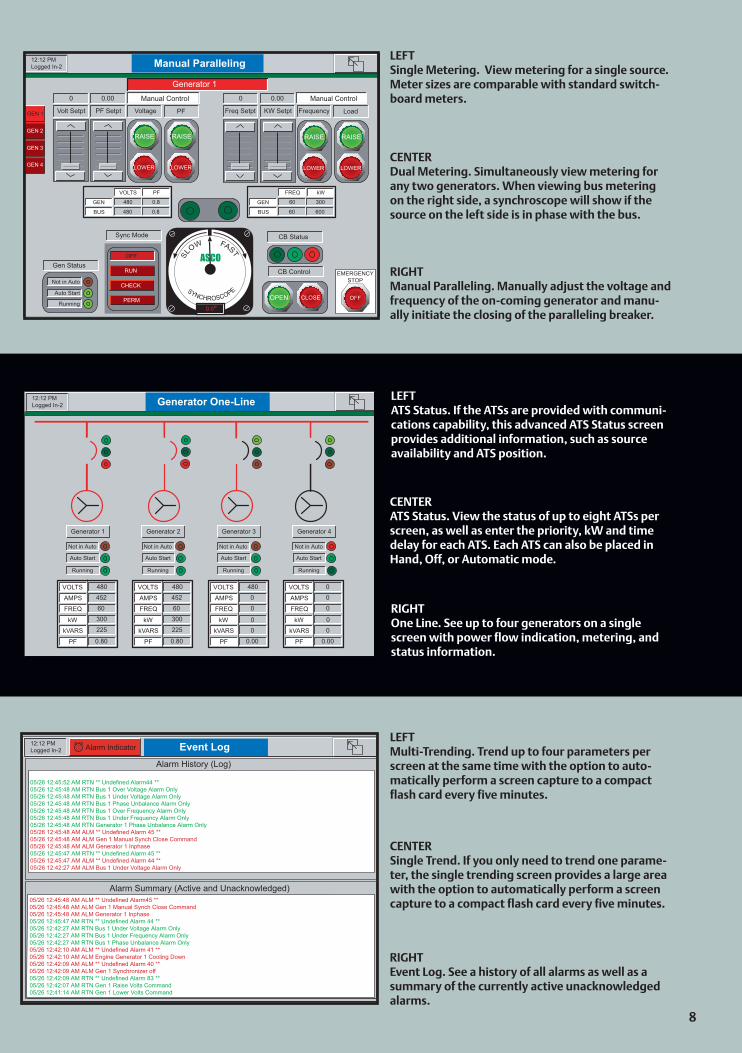
LEFTMulti-Trending. Trend up to four parameters per screen at the same time with the option to auto-matically perform a screen capture to a compact flash card every five minutes.
LEFTATS Status. If the ATSs are provided with communi-cations capability, this advanced ATS Status screen provides additional information, such as source availability and ATS position.
CENTERSingle Trend. If you only need to trend one parame-ter, the single trending screen provides a large area with the option to automatically perform a screen capture to a compact flash card every five minutes.
CENTERATS Status. View the status of up to eight ATSs per screen, as well as enter the priority, kW and time delay for each ATS. Each ATS can also be placed in Hand, Off, or Automatic mode.
CENTERDual Metering. Simultaneously view metering for any two generators. When viewing bus metering on the right side, a synchroscope will show if the source on the left side is in phase with the bus.
RIGHTOne Line. See up to four generators on a single screen with power flow indication, metering, and status information.
RIGHTEvent Log. See a history of all alarms as well as a summary of the currently active unacknowledged alarms.
RIGHTManual Paralleling. Manually adjust the voltage and frequency of the on-coming generator and manu-ally initiate the closing of the paralleling breaker.
LEFTSingle Metering. View metering for a single source. Meter sizes are comparable with standard switch-board meters.
12:12 PM
Logged In-2 Generator One-Line
Generator 1
Not in Auto
Auto Start
Running
VOLTS
AMPS
FREQ
kW
kVARS
PF
480
452
60
300
225
0.80
Generator 2
Not in Auto
Auto Start
Running
VOLTS
AMPS
FREQ
kW
kVARS
PF
480
452
60
300
225
0.80
Generator 3
Not in Auto
Auto Start
Running
VOLTS
AMPS
FREQ
kW
kVARS
PF
480
0
0
0
0
0.00
Generator 4
Not in Auto
Auto Start
Running
VOLTS
AMPS
FREQ
kW
kVARS
PF
0
0
0
0
0
0.00
12:12 PM
Logged In-2 Manual Paralleling
GEN 2
GEN 3
GEN 4
GEN 1
Generator 1
Manual Control
Voltage PF
0 0.00
PF SetptVolt Setpt
LOWER
RAISE
Manual Control
Frequency Load
0 0.00
KW SetptFreq Setpt
LOWER
RAISE
LOWER
RAISE
LOWER
RAISE
VOLTS PF
GEN
BUS
480
480
0.8
0.8
FREQ kW
GEN
BUS
60
60
300
600
CB Status
CB Control
CLOSEOPEN OFF
EMERGENCY
STOP
ASCOSLO
W FAS
T
SYNCHROSCOPE
0.0o
Sync Mode
Gen StatusRUN
OFF
CHECK
PERM
Not in Auto
Auto Start
Running
5 7 8

The next-generation technology combines a controller, touch screen operator interface, networking and I/O with programmable software for graphics and logic.
The unit provides true, integrated control of each engine-generator and simplifies power system operation, control and communication.
The controller automatically operates the system to efficiently add loads to the bus. It also ensures that engine-generators assume the highest priority loads first and manages the number of engine-generators needed to power those loads.
Operation is immediate and reliable, giving you peace of mind. Operational parameters can be set up through the touch screen, without a laptop computer.
The system controller provides power monitoring, relay protection, generator paralleling and intelligent load management functions for the emergency prime power and/or standby power system applications.
S implif y Power System ManagementAdvanced Digital Control Provides Reliability, Flexibility
The 4000 Series Generator Paralleling Switchgear debuts ASCO’s next-generation digital paralleling controller. The unit offers the reliability of an industrial programmable logic controller.
System Highlights
Dual three phase 600 Vac inputs and dual three phase 0-5 amp inputs, with true RMS sensing and phase angle relationshipsPeer-to-peer network-ing between units (CAN, Ethernet)Manual paralleling using graphical push buttons and synchroscope via master touch screen
•
•
•
The capabilities of the digital paralleling controller enable you to tailor the breadth and ease of control you want in your onsite power system.
The controller commu-nicates through an Ether-net connection with a range of building networks using most major media and protocols. Seamlessly inte-grating with your existing communications infrastruc-ture eliminates the expense of extra hardware and software, and facilitates start up.
Manual paralleling (optional) using physi-cal provisions mounted on a master door Graphical trending of the generatorsPower metering of the three phase sourcesThree phase protection on the generatorDual remote diagnos-tics with reciprocal back up—one uses an industrial-grade analog modem, the other an Ethernet IP connection
•
•
•
•
•
Optional hot-backup processor capabilityCompact flash slot and card for capturing screen displays and data for remote analysisFlexible third-party communication con-nectivityA wide selection of system optional acces-soriesChoice of two cur-rent breaker brands (Square - D or Siemens)
•
•
•
•
•
This elevation (opposite page) and one-line sche- matic show a typical, four engine-generator paralleling control switchgear configura-tion. Available distribution modules and remote control-ler can be integrated into the switchgear.
If a Generator Fails…If a generator fails while
operating in the automatic mode, the 4000 Series dis-connects it from the bus and shuts it down. The switch-gear signals the associated priority loads to shed.
The switchgear acti-vates audible and visual alarms to indicate the condi-tion. A control push-button permits operators to over-ride the load shed circuits.
If a bus overloads, causing an under-frequency condition, the switchgear automatically resets the manual override to prevent sustained bus overloading.
Managing Load Demand…
When the switchgear is set on load demand opera-tion, it automatically man-ages the number of genera-tors online, based on total power requirements.
The switchgear com-pares the actual load of the total generator bus to the running reserve capacity of total generators.
Depending on pre-de-termined kW set-points and time delays, the switchgear starts, synchronizes and soft loads generators on line. It also takes low priority en-gine-generator(s) off-line. It will soft unload the engine, open the circuit breaker and initiate the cool down sequence.
Restoring To Normal Source…
When the automatic transfer switches signal that commercial power has been restored and the transfer switches have retransferred loads to the normal source, the switchgear simultane-ously opens the generator circuit breakers.
The engines then run for a no-load, user-defined cool-down period. The con-trol system stands poised for the next power failure or regular system test.
If a bus under frequency or kW overload occurs while engine(s) are cooling down, the running units actively synchronize and parallel to the bus.
If engines are not run-ning, the control system im-mediately gives the rested engine(s) start signals and parallels them to the bus.
If a bus under frequency or kW overload occurs while generators are on line, the associated loads are shed, the condition is alarmed and a manual reset is required.
52G1
G1
G252
G2
52G3
G3 G4
G452
N E EN N EATS ATS ATS
DISTRIBUTION PANELS
52F4
52F3
F152
F252
N E ATS
UTILITY
6 9 4
Local area networks and remote networks are supported with either single or multiple points of access.
Web-enabled communica-tions allow access to your power system from any-where in the world.
ASCO communications products make it easy to monitor your prime power, emergency and/or standby power distribution systems onsite or remotely.
N e t w o r k Y o u r E m e r g e n c y Power System*
Ethernet
ASCO 5220Power Manager
Utility Power
ASCO Series 300Power Transfer
Switch
BuildingManagement
System
or RS485 MODBUS
ASCO 4000 SeriesPower Transfer
Switch
RS485
ASCO 5110Serial Module
(72A)
ASCO 5110Serial Module
(72A)
Engine-Generator Engine-Generator
ASCO 7000 Series
Power Control System
and/or RS485 MODBUS
Modbus TCP/IP
PCS Remote Annunciator
Fiber Optic EthernetPCSRemote Annunciator
or RS485
RS485 MODBUS RS485 MODBUS

Power ful Control
Main Menu. Easily navigate through all screen displays
from the Main Menu. Log in here to gain access to various
levels of information.
All screen displays can be reached directly from the Main Menu. Information is presented clearly using
easy-to-understand graphics, including both digital and analog-style displays for at-a-glance supervision.
Quickly Access Easy-to-Understand Displays
ASCO
Digital Paralleling Controller
Single Metering Dual Metering Manual Paralleling
System Setup Gen Setup Gen Protection
kW Trending Multi - Trending ATS Status
One - Line Event Log Alarm Status
Log In
12:12 PM
Logged In-2 kW Trending
400
0
0
K
W
A
T
T
S
Time (sec) 425.04
STOPGen 1 - Red
Gen 2 - Yellow
Gen 3 - Blue
Gen 4 - Green
AUTO SCREEN
CAPTURE
OFF
12:12 PM
Logged In-2 Multi Trending
STOPGen 1 - Red
Gen 2 - Yellow
Gen 3 - Blue
Gen 4 - Green
AUTO SCREEN
CAPTURE
OFF
1
0
0
0
0
K
W
A
T
T
S
Time (sec) 29.68
1
0
0
0
kW Trending 1
0
0
0
0
K
V
A
R
S
Time (sec) 29.68
1
0
0
0
kVars
3
0
0
0
Volts
Time (sec) 29.76
1
0
0
0
Voltage L - N6500
0
Frequency
Time (sec) 29.76
5500
Frequency
1 of 2 NEXT
12:12 PM
Logged In-2 ATS Status1 of 2 NEXT
ATS-1 Engine Start
Priority
101
kW
50
Time Dly.
0.0
Norm. Emer.
Byp. Act.
Source Avail.
ATS Position
Bypass Pos.
Load Shed
Hand Off Auto
ATS-2 Engine Start
Priority
102
kW
50
Time Dly.
0.0
Norm. Emer.
Byp. Act.
Source Avail.
ATS Position
Bypass Pos.
Load Shed
Hand Off Auto
ATS-3 Engine Start
Priority
103
kW
50
Time Dly.
0.0
Norm. Emer.
Byp. Act.
Source Avail.
ATS Position
Bypass Pos.
Load Shed
Hand Off Auto
ATS-4 Engine Start
Priority
104
kW
50
Time Dly.
0.0
Norm. Emer.
Byp. Act.
Source Avail.
ATS Position
Bypass Pos.
Load Shed
Hand Off Auto
ATS-5 Engine Start
Priority
105
kW
50
Time Dly.
0.0
Norm. Emer.
Byp. Act.
Source Avail.
ATS Position
Bypass Pos.
Load Shed
Hand Off Auto
ATS-6 Engine Start
Priority
106
kW
50
Time Dly.
0.0
Norm. Emer.
Byp. Act.
Source Avail.
ATS Position
Bypass Pos.
Load Shed
Hand Off Auto
12:12 PM
Logged In-2 ATS Status1 of 2 NEXT
Engine
Start
Priority 101
kW 50
Time Delay 0.0
Byp. Act.
ATS-1
Hand
Off
Auto
Load Shed
Engine
Start
Priority 102
kW 50
Time Delay 0.0
Byp. Act.
ATS-2
Hand
Off
Auto
Load Shed
Engine
Start
Priority 103
kW 50
Time Delay 0.0
Byp. Act.
ATS-3
Hand
Off
Auto
Load Shed
Engine
Start
Priority 104
kW 50
Time Delay 0.0
Byp. Act.
ATS-4
Hand
Off
Auto
Load Shed
Engine
Start
Priority 105
kW 50
Time Delay 0.0
Byp. Act.
ATS-5
Hand
Off
Auto
Load Shed
Engine
Start
Priority 106
kW 50
Time Delay 0.0
Byp. Act.
ATS-6
Hand
Off
Auto
Load Shed
Engine
Start
Priority 107
kW 50
Time Delay 0.0
Byp. Act.
ATS-7
Hand
Off
Auto
Load Shed
Engine
Start
Priority 108
kW 50
Time Delay 0.0
Byp. Act.
ATS-8
Hand
Off
Auto
Load Shed
12:12 PM
Logged In-2 Metering
BUS
GEN 2
GEN 3
GEN 4
GEN 1
Generator 1 Generator Bus Total
BUS
GEN 2
GEN 3
GEN 4
GEN 1
60
62
64
58
56HERTZ
60.00Hz
ASCO
300
400
500
200
100VOLTS
480V
ASCO
500
750
1000
250
0AMPERES
452A
ASCO
450
600
750150KILOWATTS
300kW
ASCO300
600
800
1000200
375kVA
ASCO400
VOLT AMPERES
x1000
.
0
-400
225kVAR
ASCO-200
KILOVARS
-600
200
400
600
60
62
64
58
56HERTZ
60.00Hz
ASCO
300
400
500
200
100VOLTS
480V
ASCO
1000
1500
2000
500
0AMPERES
904A
ASCO
900
1200
1500300KILOWATTS
600kW
ASCO600
600
800
1000200
375kVA
ASCO400
VOLT AMPERES
x1000
.
1200
1600
2000400
750kVA
ASCO800
VOLT AMPERES
x1000
.
1200
1600
2000400
750kVA
ASCO800
VOLT AMPERES
x1000
.
0
-800
450kVAR
ASCO-400
KILOVARS
-1200
400
800
1200
A B C
VOLTS
AMPS
PF kWH
480
452
481
450
481
450
1000.80
A B C
VOLTS
AMPS
PF kWH
480
904
481
900
481
900
2000.80
ASCOSLO
W FAS
T
SYNCHROSCOPE
12:12 PM
Logged In-2 Metering
BUS
GEN 2
GEN 3
GEN 4
GEN 1
60
62
64
58
56HERTZ
60.00Hz
ASCO
300
400
500
200
100VOLTS
480V
ASCO
500
750
1000
250
0AMPERES
452A
ASCO
450
600
750150KILOWATTS
300kW
ASCO300
0
-400
225kVAR
ASCO-200
KILOVARS
-600
200
400
600
600
800
1000200
375kVA
ASCO400
VOLT AMPERES
x1000
.
Generator 1
A B C
VOLTS 480 481 481
PF
kWH 100
0.80 A B C
VOLTS 452 450 450
Alarm History (Log)
Alarm Summary (Active and Unacknowledged)
12:12 PM
Logged In-2 Alarm Indicator Event Log
05/26 12:45:52 AM RTN ** Undefined Alarm44 **
05/26 12:45:48 AM RTN Bus 1 Over Voltage Alarm Only
05/26 12:45:48 AM RTN Bus 1 Under Voltage Alarm Only
05/26 12:45:48 AM RTN Bus 1 Phase Unbalance Alarm Only
05/26 12:45:48 AM RTN Bus 1 Over Frequency Alarm Only
05/26 12:45:48 AM RTN Bus 1 Under Frequency Alarm Only
05/26 12:45:48 AM RTN Generator 1 Phase Unbalance Alarm Only
05/26 12:45:48 AM ALM ** Undefined Alarm 45 **
05/26 12:45:48 AM ALM Gen 1 Manual Synch Close Command
05/26 12:45:48 AM ALM Generator 1 Inphase
05/26 12:45:47 AM RTN ** Undefined Alarm 45 **
05/26 12:45:47 AM ALM ** Undefined Alarm 44 **
05/26 12:42:27 AM ALM Bus 1 Under Voltage Alarm Only
05/26 12:45:48 AM ALM ** Undefined Alarm45 **
05/26 12:45:48 AM ALM Gen 1 Manual Synch Close Command
05/26 12:45:48 AM ALM Generator 1 Inphase
05/26 12:45:47 AM RTN ** Undefined Alarm 44 **
05/26 12:42:27 AM RTN Bus 1 Under Voltage Alarm Only
05/26 12:42:27 AM RTN Bus 1 Under Frequency Alarm Only
05/26 12:42:27 AM RTN Bus 1 Phase Unbalance Alarm Only
05/26 12:42:10 AM ALM ** Undefined Alarm 41 **
05/26 12:42:10 AM ALM Engine Generator 1 Cooling Down
05/26 12:42:09 AM ALM ** Undefined Alarm 40 **
05/26 12:42:09 AM ALM Gen 1 Synchronizer off
05/26 12:42:09 AM RTN ** Undefined Alarm 83 **
05/26 12:42:07 AM RTN Gen 1 Raise Volts Command
05/26 12:41:14 AM RTN Gen 1 Lower Volts Command
LEFTMulti-Trending. Trend up to four parameters per screen at the same time with the option to auto-matically perform a screen capture to a compact flash card every five minutes.
LEFTATS Status. If the ATSs are provided with communi-cations capability, this advanced ATS Status screen provides additional information, such as source availability and ATS position.
CENTERSingle Trend. If you only need to trend one parame-ter, the single trending screen provides a large area with the option to automatically perform a screen capture to a compact flash card every five minutes.
CENTERATS Status. View the status of up to eight ATSs per screen, as well as enter the priority, kW and time delay for each ATS. Each ATS can also be placed in Hand, Off, or Automatic mode.
CENTERDual Metering. Simultaneously view metering for any two generators. When viewing bus metering on the right side, a synchroscope will show if the source on the left side is in phase with the bus.
RIGHTOne Line. See up to four generators on a single screen with power flow indication, metering, and status information.
RIGHTEvent Log. See a history of all alarms as well as a summary of the currently active unacknowledged alarms.
RIGHTManual Paralleling. Manually adjust the voltage and frequency of the on-coming generator and manu-ally initiate the closing of the paralleling breaker.
LEFTSingle Metering. View metering for a single source. Meter sizes are comparable with standard switch-board meters.
12:12 PM
Logged In-2 Generator One-Line
Generator 1
Not in Auto
Auto Start
Running
VOLTS
AMPS
FREQ
kW
kVARS
PF
480
452
60
300
225
0.80
Generator 2
Not in Auto
Auto Start
Running
VOLTS
AMPS
FREQ
kW
kVARS
PF
480
452
60
300
225
0.80
Generator 3
Not in Auto
Auto Start
Running
VOLTS
AMPS
FREQ
kW
kVARS
PF
480
0
0
0
0
0.00
Generator 4
Not in Auto
Auto Start
Running
VOLTS
AMPS
FREQ
kW
kVARS
PF
0
0
0
0
0
0.00
12:12 PM
Logged In-2 Manual Paralleling
GEN 2
GEN 3
GEN 4
GEN 1
Generator 1
Manual Control
Voltage PF
0 0.00
PF SetptVolt Setpt
LOWER
RAISE
Manual Control
Frequency Load
0 0.00
KW SetptFreq Setpt
LOWER
RAISE
LOWER
RAISE
LOWER
RAISE
VOLTS PF
GEN
BUS
480
480
0.8
0.8
FREQ kW
GEN
BUS
60
60
300
600
CB Status
CB Control
CLOSEOPEN OFF
EMERGENCY
STOP
ASCOSLO
W FAS
T
SYNCHROSCOPE
0.0o
Sync Mode
Gen StatusRUN
OFF
CHECK
PERM
Not in Auto
Auto Start
Running
5 7 8

The next-generation technology combines a controller, touch screen operator interface, networking and I/O with programmable software for graphics and logic.
The unit provides true, integrated control of each engine-generator and simplifies power system operation, control and communication.
The controller automatically operates the system to efficiently add loads to the bus. It also ensures that engine-generators assume the highest priority loads first and manages the number of engine-generators needed to power those loads.
Operation is immediate and reliable, giving you peace of mind. Operational parameters can be set up through the touch screen, without a laptop computer.
The system controller provides power monitoring, relay protection, generator paralleling and intelligent load management functions for the emergency prime power and/or standby power system applications.
S implif y Power System ManagementAdvanced Digital Control Provides Reliability, Flexibility
The 4000 Series Generator Paralleling Switchgear debuts ASCO’s next-generation digital paralleling controller. The unit offers the reliability of an industrial programmable logic controller.
System Highlights
Dual three phase 600 Vac inputs and dual three phase 0-5 amp inputs, with true RMS sensing and phase angle relationshipsPeer-to-peer network-ing between units (CAN, Ethernet)Manual paralleling using graphical push buttons and synchroscope via master touch screen
•
•
•
The capabilities of the digital paralleling controller enable you to tailor the breadth and ease of control you want in your onsite power system.
The controller commu-nicates through an Ether-net connection with a range of building networks using most major media and protocols. Seamlessly inte-grating with your existing communications infrastruc-ture eliminates the expense of extra hardware and software, and facilitates start up.
Manual paralleling (optional) using physi-cal provisions mounted on a master door Graphical trending of the generatorsPower metering of the three phase sourcesThree phase protection on the generatorDual remote diagnos-tics with reciprocal back up—one uses an industrial-grade analog modem, the other an Ethernet IP connection
•
•
•
•
•
Optional hot-backup processor capabilityCompact flash slot and card for capturing screen displays and data for remote analysisFlexible third-party communication con-nectivityA wide selection of system optional acces-soriesChoice of two cur-rent breaker brands (Square - D or Siemens)
•
•
•
•
•
This elevation (opposite page) and one-line sche- matic show a typical, four engine-generator paralleling control switchgear configura-tion. Available distribution modules and remote control-ler can be integrated into the switchgear.
If a Generator Fails…If a generator fails while
operating in the automatic mode, the 4000 Series dis-connects it from the bus and shuts it down. The switch-gear signals the associated priority loads to shed.
The switchgear acti-vates audible and visual alarms to indicate the condi-tion. A control push-button permits operators to over-ride the load shed circuits.
If a bus overloads, causing an under-frequency condition, the switchgear automatically resets the manual override to prevent sustained bus overloading.
Managing Load Demand…
When the switchgear is set on load demand opera-tion, it automatically man-ages the number of genera-tors online, based on total power requirements.
The switchgear com-pares the actual load of the total generator bus to the running reserve capacity of total generators.
Depending on pre-de-termined kW set-points and time delays, the switchgear starts, synchronizes and soft loads generators on line. It also takes low priority en-gine-generator(s) off-line. It will soft unload the engine, open the circuit breaker and initiate the cool down sequence.
Restoring To Normal Source…
When the automatic transfer switches signal that commercial power has been restored and the transfer switches have retransferred loads to the normal source, the switchgear simultane-ously opens the generator circuit breakers.
The engines then run for a no-load, user-defined cool-down period. The con-trol system stands poised for the next power failure or regular system test.
If a bus under frequency or kW overload occurs while engine(s) are cooling down, the running units actively synchronize and parallel to the bus.
If engines are not run-ning, the control system im-mediately gives the rested engine(s) start signals and parallels them to the bus.
If a bus under frequency or kW overload occurs while generators are on line, the associated loads are shed, the condition is alarmed and a manual reset is required.
52G1
G1
G252
G2
52G3
G3 G4
G452
N E EN N EATS ATS ATS
DISTRIBUTION PANELS
52F4
52F3
F152
F252
N E ATS
UTILITY
6 9 4
Local area networks and remote networks are supported with either single or multiple points of access.
Web-enabled communica-tions allow access to your power system from any-where in the world.
ASCO communications products make it easy to monitor your prime power, emergency and/or standby power distribution systems onsite or remotely.
N e t w o r k Y o u r E m e r g e n c y Power System*
Ethernet
ASCO 5220Power Manager
Utility Power
ASCO Series 300Power Transfer
Switch
BuildingManagement
System
or RS485 MODBUS
ASCO 4000 SeriesPower Transfer
Switch
RS485
ASCO 5110Serial Module
(72A)
ASCO 5110Serial Module
(72A)
Engine-Generator Engine-Generator
ASCO 7000 Series
Power Control System
and/or RS485 MODBUS
Modbus TCP/IP
PCS Remote Annunciator
Fiber Optic EthernetPCSRemote Annunciator
or RS485
RS485 MODBUS RS485 MODBUS
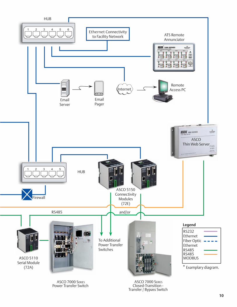
10
HUB
Remote Access PC
Ethernet Connectivityto Facility Network
EmailServer
EmailPager
To AdditionalPower TransferSwitches
ASCO 7000 SeriesPower Transfer Switch
ASCO 7000 SeriesClosed-Transition -
Transfer / Bypass Switch
Internet
ATS Remote Annunciator
RS485
ASCO 5150 Connectivity
Modules(72E)
RS232 Ethernet Fiber Optic Ethernet RS485 RS485 MODBUS
Legend
ASCO 5110Serial Module
(72A)
HUB
and/or
ASCO Thin Web Server
Firewall
* Examplary diagram.

Master Control module supervises up to eight en-gine-generators.
Options include a re-dundant processor for add-ed reliability and capacity to manage up to 64 automatic transfer switches.
The main bus is avail-able in amperages of 3000, 6000 and 10,000 at 100KAIC.
A 12 in. touch screen for controlling the power system is standard.
Single Generator With Master Control module provides the same capabili-ties as the Master Control module and includes controls and a breaker for a single generator.
It is a space-saving, compact solution for power systems with an odd num-ber of generators.
It accommodates your circuit breaker of choice and includes 100KAIC, LSIA function with an electronic trip unit.
This module also is available as a Single Gen-erator, without Master Control. The Single Genera-tor module is used in three engine-generator systems that require a redundant master controller.
Dual Generator module provides controls and circuit breakers for two engine-generators.
It is a space-saving, cost-effective solution for power systems with up to eight generators.
The main bus is avail-able in amperages of 3000, 6000 and 10,000 at 100KAIC.
It accommodates your circuit breaker of choice and includes 100KAIC, LSIA function with an electronic trip unit.
A 12 in. touch screen is optional.
Control modules offer broad flexibility to create a power control system tailored to your specific requirements.
4000 S e r i e s
Building Blocks
11
Emerson Network Power. The world leader in business-critical continuity. EmersonNetworkPower.com
AC Power Systems
Connectivity
DC Power Systems
Embedded Power
Integrated Cabinet Solutions
Outside Plant
Precision Cooling
Services
Emerson Network Power and the Emerson Network Power logo are trademarks and service marks of Emerson Electric Co. ©2007 Emerson Electric Co.
A SCO Power Te chnologies50 Hanover Road F lorham Park NE W JERSE Y 07932 USA
800 800 A SCOWWW.A SCO P OWER.CO MA SIA
AUS TRALIA
B R A Z I L
C AN A DA
GERMANY
J A PAN
ME X I CO
SOUTH AFRIC A
SOUTH AMERIC A
UNITED ARAB EMIR ATE S
UNITED KINGDOM
U N I T E D S TAT E S
Publication 3141 R3 © August, 2007 Printed in the U.S.A.
Power Switching & Controls Site Monitoring
Surge & Signal Protection
Typical Engine-Generator ConfigurationsThe 4000 Series standard engineering design demonstrates how easily you can customize a system to your specific requirements.
BELOW A Master Control module and four Dual Generator modules comprise switchgear for an eight engine-generator power system.
Two modules—a Single Generator with Master Control and a Dual Generator with redundant con-trol—comprise switchgear for a three engine power system.
Three engine systems requiring redundant master control would need three modules—Master Con-trol, Single Generator and Dual Generator.
A Master Control module and Dual Generator module comprise digital generator paralleling control switch-gear for a two engine-generator emergency, standby, and prime power system.
12

DiSCover The aweSoMe power
of The aSCo 4000 SerieS
DiGiTal GeneraTor parallelinG
ConTrol SwiTChGear
The aSCo 4000 SerieS Digital Generator parallel-ing Control Switchgear is an advanced, multiple-en-gine power control solu-tion that starts, synchro-nizes, parallels, monitors and protects emergency, standby, and prime power systems.
The 4000 power Control System gives you aSCo’s unsurpassed engine control and load management expertise.
You’re in Total Command
parallel up to eight engines and manage up to 64 automatic transfer switches.
Control a power system from easy-to-operate screens at the system, or monitor remotely from a control center or anywhere in the world over the Internet. Monitor your power 24x7x365.
Master Its Power
The 4000 Series Digital Generator Paralleling Control Switchgear is a winning combination of...
The proven and trusted features that have helped make ASCO the world leader in power transfer switching and control...
And cutting-edge, user friendly digital technology.
4000 S e r i e s System Specif ications* If the system is for a
healthcare facility, for ex-ample, can the touch screen quickly access JCAHO1 records and information to help satisfy reporting requirements?
Does it have automatic load shed control? How about a system one-line schematic overview?
The answers are, ‘Yes.’ What are your specific requirements?
Standard featuresLoad demand with operator adjustment of settingsEthernet or RS485 con-nectivity to Building Management SystemTest with loadTest without loadAutomated manual paralleling with graphi-cal synchroscopeAlarmsLCD touch screenAutomatic synchro-nizing and paralleling controls
Optional Accessories
One touch screen per Generator moduleRemote annunciationRedundant master PLCLoad control for up to 64 ATS’s
•
•
•••
•••
•
•••
Electrical operation load bank breakers(EO)Breaker lifting devices (portable or overhead)Spare partsExtended warranty
Controls Touch screen is stan-dard with the Master module; optional with Generator modulesAutomatic synchro-nizing and paralleling controlsControls hardware — Master PLC redundancy — Distributed processing — High speed CANbus
Touch Screen 12 in. color TFT on Mas-ter moduleDisplay on each pair of generators is optionalSystem overview screen with one line schematicReal time clockJCAHO records are avail-able if the generator(s) is/are properly equippedScreens:
Main MenuGenerator One-LineMeteringSystem StatusAlarm Status
•
•
••
•
•
•
•
•
•
••
•—————
ATS StatusDual MeteringkW TrendingMulti-TrendingManual ParallelingLog InEvent Log
System Control
Automatic standbyLoad management controlAutomatic load shed controlController on each gen-erator, optionalRedundant master con-trollers, optionalAutomatic generator load demand controlEmergency stop
Engine-Generator Control
Engine-generator of your choiceAutomatic engine startAdjustable engine cool-down timerAutomatic synchronizerEngine governor con-trol, load sharing, soft loading/unloadingVoltage regulator con-
———————
••
•
•
•
•
•
•
••
••
•
trol VAR/PF sharingAutomated manual paralleling
MeteringVoltage A-B, B-C, C-A (or AN, BN, CN)Current A,B,CFrequencyPower factorkWkVAR
Generator protective relaying
Device 27/59 under/over voltageDevice 81 O/U over/un-der frequencyDevice 15 Automatic synchronizerDevice 32 Reverse powerDevice 40 Loss of excita-tionDevice 25 Synch check
Engine Alarms (if properly equipped)
Low coolant tempera-ture pre-alarmHigh coolant tem-perature pre-alarm and shutdownLow oil pressure pre-alarm and shutdownLow fuel alarmLow engine battery alarm
•
•
•••••
•
•
•
•
•
•
•
•
•
••
Overcrank shutdownOverspeed shutdown
Circuit Breakers Breaker brand of your choiceDrawoutUL 1066 with two-step energy storage100KAIC Rated5 Cycle closingElectrically operated on generators and man-ually operated on dis-tributionAuxilliary and bell alarm contactsTrip unit with LSIA func-tions on generators and LSIG or LSI function on distribution
power Supply Best DC source selector systemPower from 24 VDC en-gine cranking batteriesDC-DC converter
Enclosure and Bus Constucted and labeled to UL1558 is standardUp to 600V 3 phase 4 wire AC system with 100% neutral and (25%) ground bus Main bus amperage up to 10,000 amps
••
•
••
•••
•
•
•
•
•
•
•
•
AS YOu leARN ABOuT
THe 4000 series, iT’S
NATuRAl TO ASk iF iT
CAN SATiSFY THe SPeCiFiC
RequiReMeNTS YOu HAVe
FOR A POWeR CONTROl
SYSTeM.
Silver plated copper busBraced for 100KAICNeMA 1 (3R available)ANSi GrayShipping splits at each section to ease instal-lation
Serial Based Communications
Engine network com-munications Automatic Transfer Switches
Standard for 32 ATSs, optional for 64 ATSsHard-wired start signalsHard-wired load shed relays
Building Management Network
Modbus RTU serial RS 485Modbus TCP Eth-ernet
High reliability, industri-ally hardened redun-dant capability on single pathHigh speed automation network
•••••
•
•
—
—
—
•
—
—
•
•
1. Joint Commission on Accreditation of Healthcare Organizations
* For detailed specifications please request publication 3135
1 13 14
*Dual - Generator Control Section shown with optional touch screen
Emerson Network Power. The world leader in business-critical continuity. EmersonNetworkPower.com
AC Power Systems
Connectivity
DC Power Systems
Embedded Power
Integrated Cabinet Solutions
Outside Plant
Precision Cooling
Services
Emerson Network Power and the Emerson Network Power logo are trademarks and service marks of Emerson Electric Co. ©2007 Emerson Electric Co.
A SCO Power Te chnologies50 Hanover Road F lorham Park N E W J E R S E Y 0 7 9 3 2 USA
8 0 0 8 0 0 A SCOW W W. A SCO P OWE R . CO MA SIA
AUS TRALIA
B R A Z I L
C AN A DA
GERMANY
J A PAN
ME X I CO
SOUTH AFRIC A
SOUTH AMERIC A
UNITED ARAB EMIR ATE S
UNITED KINGDOM
U N I T E D S TAT E S
Publication 3141 R3 © August, 2007 Printed in the U.S.A.
Power Switching & Controls Site Monitoring
Surge & Signal Protection
Typical Engine-Generator ConfigurationsThe 4000 Series standard engineering design demonstrates how easily you can customize a system to your specific requirements.
BELOW A Master Control module and four Dual Generator modules comprise switchgear for an eight engine-generator power system.
Two modules—a Single Generator with Master Control and a Dual Generator with redundant con-trol—comprise switchgear for a three engine power system.
Three engine systems requiring redundant master control would need three modules—Master Con-trol, Single Generator and Dual Generator.
A Master Control module and Dual Generator module comprise digital generator paralleling control switch-gear for a two engine-generator emergency, standby, and prime power system.
12