Embed Size (px)
Citation preview

TYSTAR CORPORATE CATALOG 2015

CEO’s Message
Tystar Value
Why Tystar? 33 Reasons
Tytan Furnace Systems
Photo Enhanced CVD Reactor
Instruments
Commitment to Service
01
Table of Contents
03
05
06
08
12
13
16
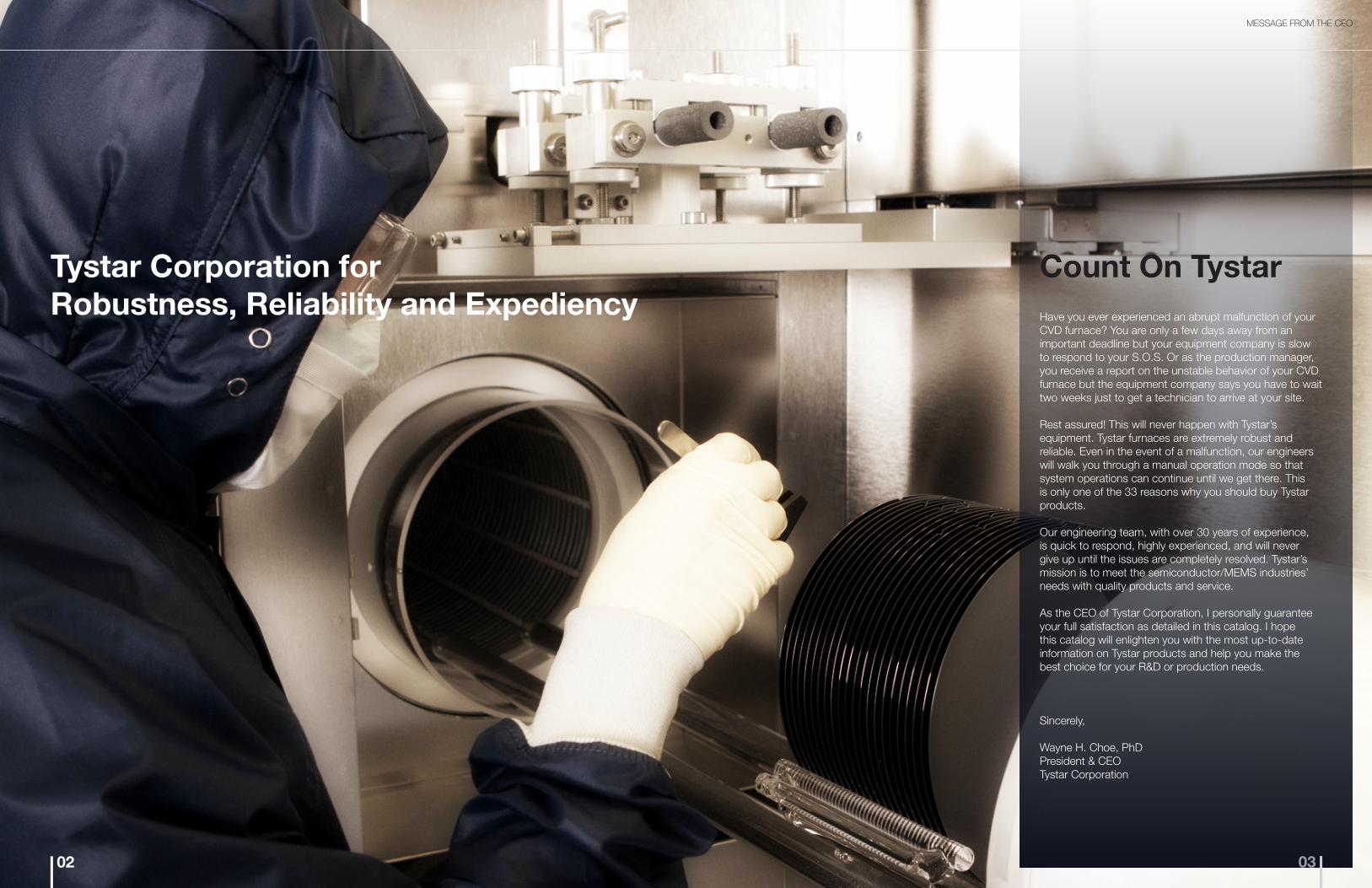
Have you ever experienced an abrupt malfunction of your CVD furnace? You are only a few days away from an important deadline but your equipment company is slow to respond to your S.O.S. Or as the production manager, you receive a report on the unstable behavior of your CVD furnace but the equipment company says you have to wait two weeks just to get a technician to arrive at your site.
Rest assured! This will never happen with Tystar’s equipment. Tystar furnaces are extremely robust and reliable. Even in the event of a malfunction, our engineers will walk you through a manual operation mode so that system operations can continue until we get there. This is only one of the 33 reasons why you should buy Tystar products.
Our engineering team, with over 30 years of experience, is quick to respond, highly experienced, and will never give up until the issues are completely resolved. Tystar’s mission is to meet the semiconductor/MEMS industries’ needs with quality products and service.
As the CEO of Tystar Corporation, I personally guarantee your full satisfaction as detailed in this catalog. I hope this catalog will enlighten you with the most up-to-date information on Tystar products and help you make the best choice for your R&D or production needs.
Sincerely,
Wayne H. Choe, PhDPresident & CEOTystar Corporation
MESSAGE FROM THE CEO
Count On Tystar
0302
Tystar Corporation for Robustness, Reliability and Expediency

05
WHY TYSTAR?
• Each process tube (chamber) has its own monitor control computer.
• The computer has multiple recipes stored.
• The computer will retain its memory for 30 days in the event of a brown or black out.
• The Temperature Controller has a dual algorithm with Feedforward as well as PID functions.
• Sliding PCB drawers and swivel control consoles are used for ease of maintenance.
• All software used in the system is SECS II compatible.
• There is power on diagnostics.
• Gas control panels and scavenger exhausts are designed with low particle generation in mind.
Advanced Features
• 24 hour response to any inquiry or service request even after the warranty expires.
• Unlimited process and system support for the entire lifetime of the equipment.
• Process data support utilizing the largest library of process data gathered over 30 years.
Excellent Post-Sales Support
• Auto/manual switching in the event of an unexpected controller failure.
• Sophisticated and high speed controls.
• Rigorously tested and certified parts.
• Individual tube control for failure independence from tube to tube.
• EPROM established safety controls.
• A multi-step abort sequence to prevent damage to the process or equipment in the event of an emergency shut down.
Robust & Reliable
Tystar’s proprietary isothermal system design enables:
• Very affordable price, beating any leading manufacturer.
• A small footprint, saving expensive clean room space.
• High efficiency through reducing gas and electricity use by >50%.
High Return on Investment
04
Tystar Value
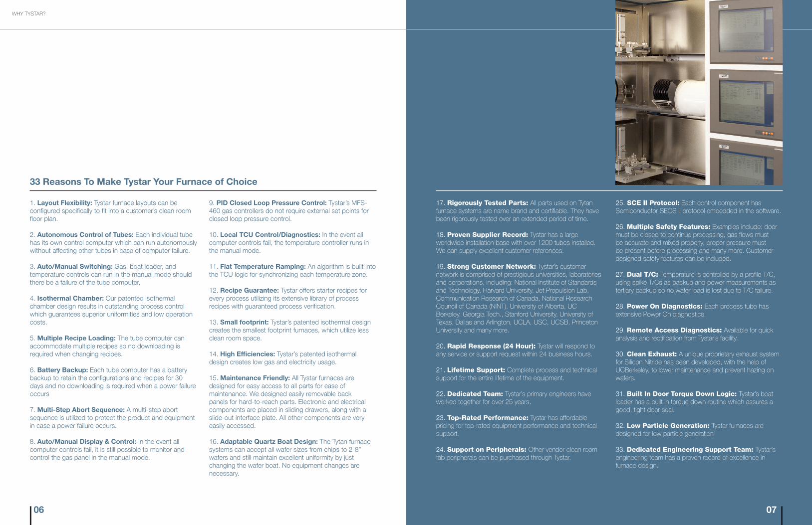
25. SCE II Protocol: Each control component has Semiconductor SECS II protocol embedded in the software.
26. Multiple Safety Features: Examples include: door must be closed to continue processing, gas flows must be accurate and mixed properly, proper pressure must be present before processing and many more. Customer designed safety features can be included.
27. Dual T/C: Temperature is controlled by a profile T/C, using spike T/Cs as backup and power measurements as tertiary backup so no wafer load is lost due to T/C failure.
28. Power On Diagnostics: Each process tube has extensive Power On diagnostics.
29. Remote Access Diagnostics: Available for quick analysis and rectification from Tystar’s facility.
30. Clean Exhaust: A unique proprietary exhaust system for Silicon Nitride has been developed, with the help of UCBerkeley, to lower maintenance and prevent hazing on wafers.
31. Built In Door Torque Down Logic: Tystar’s boat loader has a built in torque down routine which assures a good, tight door seal.
32. Low Particle Generation: Tystar furnaces are designed for low particle generation
33. Dedicated Engineering Support Team: Tystar’s engineering team has a proven record of excellence in furnace design.
17. Rigorously Tested Parts: All parts used on Tytan furnace systems are name brand and certifiable. They have been rigorously tested over an extended period of time.
18. Proven Supplier Record: Tystar has a large worldwide installation base with over 1200 tubes installed. We can supply excellent customer references.
19. Strong Customer Network: Tystar’s customer network is comprised of prestigious universities, laboratories and corporations, including: National Institute of Standards and Technology, Harvard University, Jet Propulsion Lab, Communication Research of Canada, National Research Council of Canada (NINT), University of Alberta, UC Berkeley, Georgia Tech., Stanford University, University of Texas, Dallas and Arlington, UCLA, USC, UCSB, Princeton University and many more.
20. Rapid Response (24 Hour): Tystar will respond to any service or support request within 24 business hours.
21. Lifetime Support: Complete process and technical support for the entire lifetime of the equipment.
22. Dedicated Team: Tystar’s primary engineers have worked together for over 25 years.
23. Top-Rated Performance: Tystar has affordable pricing for top-rated equipment performance and technical support.
24. Support on Peripherals: Other vendor clean room fab peripherals can be purchased through Tystar.
07
9. PID Closed Loop Pressure Control: Tystar’s MFS-460 gas controllers do not require external set points for closed loop pressure control.
10. Local TCU Control/Diagnostics: In the event all computer controls fail, the temperature controller runs in the manual mode.
11. Flat Temperature Ramping: An algorithm is built into the TCU logic for synchronizing each temperature zone.
12. Recipe Guarantee: Tystar offers starter recipes for every process utilizing its extensive library of process recipes with guaranteed process verification.
13. Small footprint: Tystar’s patented isothermal design creates the smallest footprint furnaces, which utilize less clean room space.
14. High Efficiencies: Tystar’s patented isothermal design creates low gas and electricity usage.
15. Maintenance Friendly: All Tystar furnaces are designed for easy access to all parts for ease of maintenance. We designed easily removable back panels for hard-to-reach parts. Electronic and electrical components are placed in sliding drawers, along with a slide-out interface plate. All other components are very easily accessed.
16. Adaptable Quartz Boat Design: The Tytan furnace systems can accept all wafer sizes from chips to 2-8” wafers and still maintain excellent uniformity by just changing the wafer boat. No equipment changes are necessary.
1. Layout Flexibility: Tystar furnace layouts can be configured specifically to fit into a customer’s clean room floor plan.
2. Autonomous Control of Tubes: Each individual tube has its own control computer which can run autonomously without affecting other tubes in case of computer failure.
3. Auto/Manual Switching: Gas, boat loader, and temperature controls can run in the manual mode should there be a failure of the tube computer.
4. Isothermal Chamber: Our patented isothermal chamber design results in outstanding process control which guarantees superior uniformities and low operation costs.
5. Multiple Recipe Loading: The tube computer can accommodate multiple recipes so no downloading is required when changing recipes.
6. Battery Backup: Each tube computer has a battery backup to retain the configurations and recipes for 30 days and no downloading is required when a power failure occurs
7. Multi-Step Abort Sequence: A multi-step abort sequence is utilized to protect the product and equipment in case a power failure occurs.
8. Auto/Manual Display & Control: In the event all computer controls fail, it is still possible to monitor and control the gas panel in the manual mode.
33 Reasons To Make Tystar Your Furnace of Choice
WHY TYSTAR?
06

M I N I S E R I E S
WAFER SIZE
TUBES ( UP TO )
FURNACE MODEL
WAFERS PER TUBE
MAXIMUM POWER
FOOTPRINT( LENGTH, HEIGHT, DEPTH )
FLAT ZONE
6”
≤ 3 TUBES
3600
100 ATM
50 LPCVD
40 KVA
LHD
126”69”30”
18”
8”
1 TUBE
1800
100 ATM
50 LPCVD
28 KVA
LHD
63”54”30”
18”
8”
≤ 3 TUBES
3800
100 ATM
50 LPCVD
45 KVA
LHD
134”82”30”
18”
6”
1 TUBE
1600
100 ATM
50 LPCVD
18 KVA
LHD
63”54”30”
18”
6”
≤ 4 TUBES
4600
100 ATM
50 LPCVD
50 KVA
LHD
127”82”30”
18”
S TA N D A R D S E R I E S
8”
≤ 3 TUBES
8300
200 ATM
100 LPCVD
75 KVA
LHD
164”82”30”
34”
6”
≤ 4 TUBES
2000
200 ATM
100 LPCVD
60 KVA
LHD
164”82”30”
34”
8”
N/A
≤ 3 TUBES
8342
500 ATM
87 KVA
LHD
164”82”34”
42”
8”
N/A
≤ 4 TUBES
8442
500 ATM
113 KVA
LHD
164”92”34”
42”
S O L A R S E R I E S
WAFER SIZE
TUBES ( UP TO )
FURNACE MODEL
WAFERS PER TUBE
MAXIMUM POWER
FOOTPRINT( LENGTH, HEIGHT, DEPTH )
FLAT ZONE
TA B L E T O P S E R I E S
WAFER SIZE
TUBES ( UP TO )
FURNACE MODEL
MAXIMUM POWER
HEATER ZONES
FLAT ZONE
8”
1 TUBE
1080
8”
5
18 KVA
6”
1 TUBE
1060
8”
5
12 KVA
6”
1 TUBE
160
12”
3
18 KVA
2”
1 TUBE
120
12”
3
16 KVA
3
10”
5 KVA
2”
1 TUBE
1020
N A N O S E R I E S
AUTOMATED TYTAN ATMOSPHERIC/LPCVD FURNACE SYSTEMS
09
Tytan Standard Series 8300
Tytan Solar Series 8442
Tytan Standard Series
The Tytan Standard Systems are designed for diffusion, oxidation and LPCVD applications. The systems are compact and suitable for use in manufacturing and/or R&D environments. The Standard series have been well accepted as dependable process tools both in the industry and in the R&D community. They offer superior performance and process uniformities. The design incorporates several of the most advanced concepts required for high performance wafer processing tools.
Tytan Furnaces
08

Tytan Tabletop Series
The Tytan Tabletop Systems are designed to provide high-quality resistance-heated thermal processing on a budget. The systems provide phenomenal performance and are repeatable with tight control. The interface and trace data/status display/recipe management software all provide seamless usability on the user’s end, and the systems are very safe and durable.
M I N I S E R I E S
WAFER SIZE
TUBES ( UP TO )
FURNACE MODEL
WAFERS PER TUBE
MAXIMUM POWER
FOOTPRINT( LENGTH, HEIGHT, DEPTH )
FLAT ZONE
6”
≤ 3 TUBES
3600
100 ATM
50 LPCVD
40 KVA
LHD
126”69”30”
18”
8”
1 TUBE
1800
100 ATM
50 LPCVD
28 KVA
LHD
63”54”30”
18”
8”
≤ 3 TUBES
3800
100 ATM
50 LPCVD
45 KVA
LHD
134”82”30”
18”
6”
1 TUBE
1600
100 ATM
50 LPCVD
18 KVA
LHD
63”54”30”
18”
6”
≤ 4 TUBES
4600
100 ATM
50 LPCVD
50 KVA
LHD
127”82”30”
18”
S TA N D A R D S E R I E S
8”
≤ 3 TUBES
8300
200 ATM
100 LPCVD
75 KVA
LHD
164”82”30”
34”
6”
≤ 4 TUBES
2000
200 ATM
100 LPCVD
60 KVA
LHD
164”82”30”
34”
8”
N/A
≤ 3 TUBES
8342
500 ATM
87 KVA
LHD
164”82”34”
42”
8”
N/A
≤ 4 TUBES
8442
500 ATM
113 KVA
LHD
164”92”34”
42”
S O L A R S E R I E S
WAFER SIZE
TUBES ( UP TO )
FURNACE MODEL
WAFERS PER TUBE
MAXIMUM POWER
FOOTPRINT( LENGTH, HEIGHT, DEPTH )
FLAT ZONE
TA B L E T O P S E R I E S
WAFER SIZE
TUBES ( UP TO )
FURNACE MODEL
MAXIMUM POWER
HEATER ZONES
FLAT ZONE
8”
1 TUBE
1080
8”
5
18 KVA
6”
1 TUBE
1060
8”
5
12 KVA
6”
1 TUBE
160
12”
3
18 KVA
2”
1 TUBE
120
12”
3
16 KVA
3
10”
5 KVA
2”
1 TUBE
1020
N A N O S E R I E S
Tytan Tabletop Series 1020
Tytan Nano Series 160
AUTOMATED TYTAN ATMOSPHERIC/LPCVD FURNACE SYSTEMS
11
Tytan Mini Series
The Tytan Mini Furnace Systems are designed for diffusion, oxidation and LPCVD applications. The systems require considerably less floor space and electrical power than conventional furnaces of equal capacity. The Mini tools are used both in the semiconductor/MEMS industry and in the R&D community. They offer superior performance and process uniformities. The design incorporates several of the most advanced concepts required for high performance wafer processing tools.
M I N I S E R I E S
WAFER SIZE
TUBES ( UP TO )
FURNACE MODEL
WAFERS PER TUBE
MAXIMUM POWER
FOOTPRINT( LENGTH, HEIGHT, DEPTH )
FLAT ZONE
6”
≤ 3 TUBES
3600
100 ATM
50 LPCVD
40 KVA
LHD
126”69”30”
18”
8”
1 TUBE
1800
100 ATM
50 LPCVD
28 KVA
LHD
63”54”30”
18”
8”
≤ 3 TUBES
3800
100 ATM
50 LPCVD
45 KVA
LHD
134”82”30”
18”
6”
1 TUBE
1600
100 ATM
50 LPCVD
18 KVA
LHD
63”54”30”
18”
6”
≤ 4 TUBES
4600
100 ATM
50 LPCVD
50 KVA
LHD
127”82”30”
18”
S TA N D A R D S E R I E S
8”
≤ 3 TUBES
8300
200 ATM
100 LPCVD
75 KVA
LHD
164”82”30”
34”
6”
≤ 4 TUBES
2000
200 ATM
100 LPCVD
60 KVA
LHD
164”82”30”
34”
8”
N/A
≤ 3 TUBES
8342
500 ATM
87 KVA
LHD
164”82”34”
42”
8”
N/A
≤ 4 TUBES
8442
500 ATM
113 KVA
LHD
164”92”34”
42”
S O L A R S E R I E S
WAFER SIZE
TUBES ( UP TO )
FURNACE MODEL
WAFERS PER TUBE
MAXIMUM POWER
FOOTPRINT( LENGTH, HEIGHT, DEPTH )
FLAT ZONE
TA B L E T O P S E R I E S
WAFER SIZE
TUBES ( UP TO )
FURNACE MODEL
MAXIMUM POWER
HEATER ZONES
FLAT ZONE
8”
1 TUBE
1080
8”
5
18 KVA
6”
1 TUBE
1060
8”
5
12 KVA
6”
1 TUBE
160
12”
3
18 KVA
2”
1 TUBE
120
12”
3
16 KVA
3
10”
5 KVA
2”
1 TUBE
1020
N A N O S E R I E STytan Mini Series 460010

13
Gas Control Systems
Tystar’s gas control equipment provides precise control and mixing of industrial process gases used not only in the semiconductor but also in many other industries. The gas panels use compact, modular designs and are fabricated from 316 stainless steel with orbitally-welded joints and connections. They are leak tested to 10-8 cm3/s with helium.
The Tystar MFS 460 Electronic Gas Controller directs the process gas flows of up to six individual mass flow controllers. In either manual or automatic mode, the MFS 460 monitors gas flows, provides flow error bands, and displays set points and actual gas flows. For low-pressure CVD applications, the unit provides reactor pressure readout and closed-loop pressure control. The MFS 460 also stores gas interlocks, gas ratio controls and error bands in an EPROM, guaranteeing safe handling of all process gases. It interfaces (via an RS 232 serial communication data link) with the master controller, such as the Tystar FCS 10. The MFS 460 Electronic Gas Controller provides safety interlocks and other critical gas control features.
MFS 460 Electronic Gas Controller
Ambient Operating Temperature
Environmental
5°C to 43°C (40°F to 110°F)
Mass Flow Controllers
Set Point Out
Analog Singal
Output Impedance
Input Impedance
Digital Input
Gas Flow Loops
Shut-off Valve
Thermocouple Input
Serial Communication
Parallel Remote Control
Keyboard
Alphanumeric Display
For All Standard Models
0...5 VDC
0...+5 VDC
6 Ohms
25 Ohms
On/Off TTL Level with 4.7 kOhm Pullup Resistor
Up to Six
+24VDC OutOutput open collector
Type R, 300 - 1375o C Range
RS 232C Maximum Cable Length 25 ft./8m
0-5 VDC, Contact Closure, Input/Output
Membrane Switch 4x4 Matrix
10 Digit, 14 Segment Vacuum Flourescent
Interface
Dimensions
Height
Width
Depth
Weight
10.8 in. / 275 mm
6.0 in. / 152 mm
ATM 8.5 in. / 216 mmLPCVD 9.75 in. / 248 mm
MAX 7.9 lbs / 3.6 kg
Electrical
Power
Power Consumption
Power Supply
Regulated: (< 0.5% variation)
Unregulated:
85 to 264 VAC ±10%, 47/63 Hz
153 W max
+5VDC/15A, +15VDC/2A, -15VDC/2A, 24VDC/3A
5VAC/0.48A
INSTRUMENTS
Photo-Enhanced CVD Reactors
The Tystar PVD 1000 Photo-Enhanced CVD Reactor uses ultraviolet light as an energy source for activating process gases for the deposition of dielectric films at low temperatures (<150ºC). Films of silicon dioxide (SiO2), silicon nitride (Si3N4), silicon oxy-nitride (SiON) and others can be deposited. Minimal stress is observed in these films due to the low deposition temperature. Since the UV photon energy used does not ionize the process gases, no radiation damage from charged particles has been observed.
The PVD 1000 deposited films offer excellent step coverage. The PVD 1000 system is available with single- or dual-process chambers. The PVD 1000 reactor is used in a variety of applications for film deposition on “III/V” materials, such as gallium arsenide, indium antimonide and other materials that cannot tolerate higher deposition temperatures.
PHOTO-ENHANCED CVD REACTORS
Film Density
Refractive Index
Dielectric Constant
Dielectric Strength
Particle Density
Film Adhesion (Tension)
Etch Rate
Thickness Uniformity Across Substrate
Thickness Repeatability
Deposition Rate (150oC, 1 Torr)
Cycle Time (1500Å)
Substrate Temperature
Reactor Pressure
< ±8%
< ±5%
60 Å/min.
55 min.
50 - 250oC
0.3 - 0.5 Torr
< ±5%
< ±3%
120 Å/min.
45 min.
50 - 250oC
0.3 - 1 Torr
PVD 1000 Process Data
PVD 1000 Film Characteristics
1.8 - 2.4 g/cm3
1.8 - 2.0
5.5
4 x 10⁶ V/cm
< 10/cm2
7 x 10⁶ Pa
60 - 100 Å/sec. 1)
1) 1:10HF
2.10 g/cm3
1.45 - 1.48
3.9
6 x 10⁶ V/cm
< 10/cm2
70 x 106 Pa
90 Å/sec. 2)
2) B.O.E.
Si3N4
Si3N4
SiO2
SiO2(TYPICAL DATA)
Input Power
208 / 220 VAC, 3 Phase, 40 A, 60 Hz
220 / 380 VAC 3 Phase, 25 A, 50 Hz
PVD 1000 REACTOR SPECIFICATIONS
Height
Depth
Width
Weight
41 in. / 1041 mm
28 in. / 711 mm
81 in. / 2057 mm
970 lbs. / 427 kg
Dimension / Weight
Gas SuppliesReactant GasesFittings: 1/4” Metal Face Seals (VCR)
SiH4
NH3
N2O
20 sccm / 15 psi
200 sccm / 20 psi
200 sccm / 20 psi
Electrical Power
12

15
The Tystar MFC Tester is an inexpensive, hand held, lightweight instrument for the testing of most commercial Mass Flow Controllers and Mass Flow Meters (MFC’s) with a standard 20-pin card edge connector. The data are displayed on a large backlit LCD. A miniature rotary switch is used to select different test points of the Mass Flow Devices. At the back of the instrument is a Printed Circuit Board, PCB, with test points for manual purge or closing the valve of the MFC. It can be used remotely at some distance from the gas control panel, which is sometimes hard to reach. The MFC Tester can measure a number of the following voltages (Set Point, Flow Output, Valve, Zener, and Supply Voltages).
Mass Flow Device Tester (MFC Tester)
Display
Switch Positions
Maximum Voltage Range
Accuracy
Sampling Rate
Supply Voltage
Supply Current
Input Independence
Over-ranage Indication
Operating Temperature
Size
Weight
0.4”/1.2 mm, Backlit LCD
Off, Control, Output, Valve, Zener Diode, ± 15 V
±20 VDC
±0.02% Full Scale
2.5 per second
+5.00 VDC, (Regulated from MFC Power Supply)
37 mA
1 M Ω
Yes
0-50° C
3.8” x 2.4” x 1.0” (96 x 61 x 25 mm)
3.5 oz (100 g)
Specifications
INSTRUMENTS
The Tystar CAL-STAR 400 Mass Flow Calibrator is a portable, secondary standard test instrument designed for easy field calibration of all commercially available mass flow meters and mass flow controllers with standard pin configuration.
The CAL-STAR 400 includes four precision Mass Flow Meters (Flow Standards) with selected ranges from 0 to 10 slpm as reference units. The reference Mass Flow Meters are calibrated with traceability to NIST Standards.
The CAL-STAR 400 comes with an optional Windows-based data collection software which inputs data obtained in real-time to a built-in spreadsheet program. The data can be represented in graphical form for further analysis and evaluation. For each flow calibration, a graph is created which compares the test unit with the standard readout. The test data are transferred to a word processor where a calibration document is generated. The CAL-STAR 400 data collection software has a user friendly menu for easy access to new and previously saved calibration data.
CAL-STAR 400 Mass Flow Calibrator
14
Accuracy +/-1.0% of full scale
Repeatability +/-0.2% of full scale
Settling Time <1.5 seconds
Linearity +/-0.5% of full scale
10-60 psig (69-413 kPa)
Temperature 0 ... 50oC
Performance
Standard Ranges: 0 - 200 sccm
0 - 1 slpm
0 - 5 slpm
0 - 10 slpm
Other ranges at request
Warm-up Time 30 minutes
Mechanical
Gas Fittings:
Gas Tubing:
Leak Integrity:
1/4” Face Seal
(VCR) inlet and oulet
316L SS/15u in. Ra
<10-9 atm cm3/sec He
Dimensions
Height:
Width:
Depth:
Weight:
7.0” / 185 mm
16.5” / 420 mm
12.6” / 320 mm
43 lbs / 19 kg
Electrical
Input Power: 115 VAC/.77 A or
230 VAC/1.2 A
ON/OFF Power Switch
Flow Standard/Test Unit Display Switch
Flow Standard Selection Switch
Auto-Zero Switch
Set Point Selection Digital Switch
Test Unit Electrical Connection
Gas Inlet/Outlet Fittings
5-Digital Set Point/Flow Digital Display Meter
Gas Pressure
Controls & Functions
INSTRUMENTS

Tystar offers complete training for all of our systems and components, either at our headquarters or at the customer site.
The objective of Tystar’s Tytan Furnace System Training Seminar Classes is to make buyer representatives familiar with the design, operation, service and maintenance of the Tytan Furnace System. Specific items discussed in detail are installation, set-up, operation, troubleshooting and repair of the entire furnace system and its subassemblies, electronic controls, assemblies and printed circuit boards. Printed seminar materials and notes will be provided to participants at no cost. This seminar provides participants an opportunity to gain in-depth knowledge into the theoretical and practical aspects of Tystar equipment. The material presented will be in a logical, step-by-step sequence through lectures, demonstrations and practical “hands-on” exercises.
Training and Seminar Classes
7050 Lampson AvenueGarden Grove, CA 92841
tel (310) 781-9219fax (310) 781-9438
http://www.tystar.com
TYSTAR CORPORATION
The complexity of modern semiconductor process equipment and the scarcity and high cost of knowledgeable, experienced service engineers make a service contract with Tystar an intelligent choice. Drastically reduced equipment downtime, fast, efficient service by factory trained service engineers, protection from unexpected repairs, upgraded software packages, etc. are some of the benefits of a Tystar Service Contract.
Repair and maintenance service for Tystar’s furnace and CVD equipment is provided by our field service engineers, strategically located in different parts of the world. We provide assistance in equipment start up and process technology, equipment trouble shooting and repair at the customer facility.
Tystar has a complete repair, test and calibration facility at its headquarters. All electronic circuit boards, process controllers, gas control equipment, temperature controllers, vacuum components, etc. can be repaired, calibrated and tested to the original equipment specifications.
Service and Repairs
Tystar maintains a well stocked inventory of major spare parts at its facility in Garden Grove, CA. Minimum stock of critical parts is maintained. Spare parts or direct replacements for all Tytan furnaces and PVD 1000 installed systems are available. Tystar guarantees the availability of identical or equivalent-in-function spare parts for a minimum of 10 years from date of equipment purchase.
Spare Parts Inventory
Remote Service
Tystar offers Remote Monitoring & Diagnostics Service (RMDS) plans that take advantage of the most up-to-date Internet technology. A majority of the system problems may be resolved over an Internet connection, eliminating the need for travel time and expense. The customer can purchase a service plan and get immediate attention from our technical staff for any system malfunction. Should there arise a need for repair or service, our staff can remotely monitor and diagnose the system. RDMS is a new way the customer can cut down on the cost of service while enabling quick actions on the system.
COMMITMENT TO SERVICE
16

TYSTAR CORPORATE CATALOG 2015