Embed Size (px)
Citation preview

EVEN
T
5504
ITS
0416
5U
300
U
6504
70M
100
0420
504
355
04
--- 10 a U
10 15 U
25 36 30 36 30
35/
3335 30 35
1-
ON
ETU
RN
AD
VA
NTA
GE
2-
TWO
10
65
AD
VA
NTA
GE
3--
THR
EETU
RN
AD
VA
NT
AG
E4
-FO
UR
TUR
NA
DV
AN
TAG
EA
-O
NE
TUR
NEX
CH
AN
GE
ZON
E6
-T
WO
TUR
NE
XC
HA
NG
EZ
ON
E
CC
OM
MO
MEX
CH
AN
GE
ZON
EO
-‘T
HRE
ET
UR
NE
XC
HA
NG
EZ
ON
EX
-A
CC
ELER
ATI
ON
ZON
E
3 z U’
400
ME
TE
RE
VE
NT
MA
RK
ING
SLA
YO
UT
p.c
:
SEC
ON
D0004000€-O
X1
00
/4R
ELA
YF
/OIl
005044400—
412006
604.
205460
00004000
4020044
RE
LA
Y
NO
.O
FH
UR
DLE
S
HU
RD
LE
SET
RN
GS
BO
YS
CO
MP
ET
ITiO
N
C U
EM
IT0
55
15
00
8-4
UTO
ON
6000
ON
CHE
X>H
UR
DL
EST
AR
TTO
LA
STH
UR
DLE
HEI
GH
TFI
RST
HU
RDLE
IB
ETW
EEN
HU
RD
LES
TOFT
NSH
13.7
1EN
(4S
FT.)
,L.S
344
U(3
5FT
.)4.7
O8M
(5A
1F
j,5.7
1E
M.(
4.5
iY”>
6.1
44041
30
FT.)
19
.IO
OM
I5.O
5fl
,>1628004160
FT
j2S
p6O
,)166U
8M
(E
135F
TJ
RC
.2
GIR
LS
CO
MP
ET
ITIO
N
1304(4
267
FT.>
fU
UM
(2100
FT
>I
RU
(20
25F
TL
.13
0414
2.67
FT.>
6.5
U(2
7.90
FT.>
.jT
IM(3
6.06
FT.)
13
M(4
2.67
FT.)
_0.5
04(2
7.00
FT.>
jlo.U
U(3
4.45
FT.
STA
RT
ALL
EV
EN
TS
(EX
CEP
TOlO
OM
,1
1504,
2000
4,32
004
,10
0204
,30
05M
)
•0.
•0
RU
LE
5.3.
0
SEC
ON
D00
0100
40€
4S
20
01
4R
EL
AY
00*2400
6000
4100
€P
000004040004
RE
LA
Y
100*
45
01
10
:11
0
SL
OP
E00
*230
0006
75:
LA
TE
RA
L-2
.10
0O
1E
CO
I/IR
D000
AL
LL
UT
ES
TO
TOE
INSO
lE)
0514
10M
G0
#E
C0
0N
I1
05
0

C)
CU
C)
Cz
z0U.’Cl)
C.)
I.—
0-£3.
34

RU
NW
AY
SO
NB
AC
KST
RA
IGH
T
Not
e:F
oreq
ual
quad
rant
trac
k
—O
PT
ION
AL
1
LO
NG
IT
RIP
LE
JUM
P

a,
Not
e:F
oreq
ual
quad
rant
trac
k
RU
NW
AY
SO
UT
SID
EO
FT
RA
CK

LU>
DC)LU
Cl)
zD
C.)
C
1’
Cz
37

INT
ER
NA
TIO
NA
LB
RO
KE
N-B
AC
KC
UR
VE

“C,
-I
C)
-UI
z0‘1mI
C)0z‘10C
0z

400
MET
ER.
ST
AN
[)A
D(A
AF
TIA
CK
FIG
UIE
2-5
55O
OM
___
7
I13
2.00
MTO
142.
00M

CONVERTING MANUAL TIMES TO FULLY AUTOMATIC TIME
HIGH JUMP — The inclination in the high jump approach shall not exceed 1:100 (1%).The approach shall consist of a semicircle of level and unvarying surface. The center of the
semicircle or rectangle is to be the midpoint between the standards. The depth of the approachshould be a minimum of 50 feet.
The landing pad shall not be less than 16 feet (4.80 m) wide by 8 feet (2.40 m) deep. The material in the pad shall be high enough and of a composition that will provide a safe landing. The rulescommittee strongly recommends the use of 24 inches (60 cm) of foam rubber or shock-absorbingsynthetic soft material or an encased commercially compressed foam rubber mattress at least 18inches (45 cm) thick. When the landing pad is made up of two or more sections, they shall beattached or include a common cover or pad extending over all sections. Hard and unyielding surfaces, such as concrete, wood or asphalt, that extend out from beneath the sides and back of thehigh-jump landing pad shall be padded with a minimum of 2-inch dense foam or other suitable material.
NOTE: It is recommended that any excess material such as asphalt or concrete that extends outfrom beneath the side or back of the landing pad be removed.The upright standards which support the crossbar shall be at least 12 feet apart. The platforms
which support the crossbar shall be rectangular planes 1/2 inches by 23/B inches. The long dimensions shall point toward the opposite upright so that it will be parallel to the crossbar. There may bean extension of the standard above the crossbar. The base of the standards shall not be moved during the competition, and its position should be marked with tape prior to the start of competition.
The crossbar shall not be less than 12 feet (3.66 m) or more than 14 feet, 10 inches (4.52 m) inlength, of uniform thickness and shall have a weight of not more than 5 pounds. It may be squarewith beveled edges and not more than 11/a inches in thickness; or triangular with each face not morethan 1/6 inches; or circular with a diameter of not more than 1 3/16 inches and with the ends flattened to a surface 1/)6 inches by 6 inches to 73/4 inches (1 50-200 mm).
NOTE: Effective January 1,2013, the crossbar shall be circular. Square with beveled edges ortriangular crossbars shall no longer be legal for competition.
The NFHS formula for converting Manual Time (MT) to Fully Automatic Time (FAT):
Hand-held times are rounded-up to the slower 1/10th of a second before adding the conversionfactor of .24 seconds, between fully automatic timing (FAT) and manual timing (MT), which mustbe used when converting times (i.e., MT + .24 = FAT).
Landing System
41
130’— 147’6”(PREFERRED)
142’- 160’ RUNWAY
TAKEOFFBOARD
(8” MINIMUM24” MAXIMUM WIDTH)
LONG JUMP AND TRIPLE JUMP — Inclination in the approach shall be limited to 2:100 (2%)laterally and 1:1,000 (0.1%) in the jumping direction.The runway should have a minimum length of 130 feet, and where conditions permit it shouldbe 147 feet, 6 inches measured from the long-jump scratch line. The runway should be 42 incheswide whenever possible.Equipment shall meet the following standards. The takeoff area shall be marked by a rectangular shaped takeoff board, manufactured from wood or synthetic material which provides a firm base,the width of which shall be between 8 inches (minimum) and 24 inches (maximum) and 42 inchesto 48 inches long. The takeoff board shall be set firmly in the ground level with the runway and thesurface of the landing pit. If the takeoff board is 8 inches wide, an additional 8 inches of firm, resilientmaterial may be placed so that it abuts against the edge of the takeoff board farthest from the scratch
On hard surfaced runways, a painted scratch line of a contrasting color and with the same sizespecifications may be used in lieu of a takeoff board.The landing pit shall be filled with sand or other soft material to a depth that will ensure a safelanding. The surface shall have the same elevation as that of the take-off board. The landing pit shallhave a minimum width of 9 feet and a minimum length of 15 feet. The scratch line is the hairlinewhich is used to mark the limit of a competitors run during a trial. The scratch line shall be locatedby measuring from the nearer edge of the landing pit a distance of approximately:
GIRLS8 feet24 feet
(NOTE: Distance from scratch line, or takeoff board may be adjusted to accommodate different levels of competition.)
line.
8’- 12’ 15—26’
RUNWAY•• j
— I
LONG JUMPLANDING AREA
6” X 18” CONCRETEPERIMETER CURB
Long JumpTriple Jump
BOYS12 feet32 feet
42

POLE VAULT — Inclination shall be limited to 2:100 (2%) laterally and 1:1,000 (0.1%) in therunning direction in the jumping direction.
The vaulting pole may be of any material and of any length and diameter. It may have a bindingof not more than two layers of adhesive tape of uniform thickness. However, the bottom of the polemay be protected by several layers of tape, PVC, metal, sponge rubber or other suitable material toprotect it when placed in the planting box.
LANDING SYSTEM: The standards or uprights shall be set to position the crossbar from a point15.5 inches (40c) beyond the vertical plane of the top of the stopboard, up to a maximum distanceof 31 .5 inches (80c) in the direction of the landing surface.
RUNWAY: A mark or marker shall not be placed on the runway, but it is permissible to placemarkers at the side of the runway. Meet management may provide check marks, not more than threeinches long, on the runway. Starting at the back of the planting box, mark intervals in the followingmanner: 6’, 7’, 8’, 9’, 10’, 11’, 12’, 13’, 20’, 30’, 40’, 50’, 60’, 70’, 80’, 90’, 100’, 110’, 120’.
Diagram B
19’8”
Restrictedmovement ofbar
Standard
Maximum distance from topof stopboard ofplanting box topad is 3”
31.5” (80c)
_5.5” (40c)
—0
Standard
Maximum widthacross bottom ofcutout for plantingbox shall be 36”
Diagram C
16’5”
43

I tie recommended length of the runway is a minimum of 130 feet (40 m). Where conditions permit, it should be 147 feet, 6 inches (45 m). The runway should be 42 inches (1.07 m) wide whenever possible.The overall size of the pole vault landing system shall be a minimum of 19 feet, 8 inches (6 m) widby 20 feet, 2 inches deep. The landing surface measured beyond the back of the standard bases, shalbe a minimum of 19 feet, 8 inches (6 m) wide. The dimension of the landing surface in back of thEvaulting box to the back of the landing system shall be 16 feet, 5 inches (5 m) deep. The material irthe system shall be high enough and of a composition that will decelerate the landing. When the landing system is made up of two or more sections, the landing surface shall include a common cover oipad extending over all sections.The front sections of the landing system, known as front buns, shall be a minimum of 16 feet, 5inches (5 m) wide so as to cover the entire area around the landing box to the inside edges of the standard bases up to the front edge of the plant box. The maximum cutout for the planting box shall be36 inches (914 mm) in width, measured across the bottom of the cutout. The edges of the front of thelanding system immediately behind the planting box shall not be placed more than 3 inches (76 mm)from the top of the back of the planting box. The front pad shall be attached to the main landing pador encased in a common cover.NOTE 1: In the pole vault, the front cutout tapered away from the planting box allows the pole tobend uninhibited.Hard or unyielding surfaces, such as but not limited to concrete, metal, wood or asphalt around thelanding pad, or between the planting box and the landing system, shall be padded or cushioned witha minimum of 2 inches (50 mm) of dense foam or other suitable material(s).NOTE 2: It is recommended that any excess material such as asphalt or concrete that extends outfrom beneath the landing pad be removed.The width between the pins that support the crossbar shall be not less than 13 feet, 8 inches(4.16m) or more than 14 feet, 8 inches (4.48m) apart. The pins shall be round, of uniform thicknessnot exceeding ½ inch (13 millimeters) in diameter, with the upper surfaces smooth, without indentations or aids of any type which might help hold the crossbar in place.The pins shall project at right angles from the side which is opposite the runway and shall notexceed 3 inches (76 millimeters) in length from the upright. Cantilevered uprights may be used. Thespecifications for the crossbar are the same as those for the high jump. The standards shall have allexposed projections on the base covered or padded and be secured in a way as to prevent them fromtipping over.The nonmetal crossbar shall be 14 feet, 10 inches (4.52m) in length, of uniform thickness, andshall have a weight of not more than 5 pounds. It may be square with beveled edges and not morethan 11/8 inches in thickness; or triangular with each face not more than 1/16 inches; or circular witha diameter of not more than 1/16 inches and with the ends flattened to a surface of inches by 6-71/4 inches (1 50-200 millimeters).NOTE 3: Effective January 1, 2013, the crossbar shall be circular. Square with beveled edges or triangular crossbars shall no longer be legal.A planting box shall be located midway between the standards. This box shall be constructed ofconcrete, fiberglass, metal, or other hard surface material into which the vaulting pole is placed sothat the top edges are at ground level. The front edge of the box shall not extend above the grade ofthe runway surface. The box shall be of dimensions indicated in the accompanying Diagrams A andB (page 44), and it shall be placed so the top edges are at ground level. The box in Diagram B shallbe constructed so that the sides slope outward at the end nearest the landing pit.The stopboard at the end of the planting box shall be placed at an angle of 105 degrees with thebase of the box.The runway adjacent to the pole vault box may be marked by a permanent line, ½ inch or 1 cmdrawn through the top (zero point) of the vault box extending 10 feet (3 meters) to each side of thebox.NOTE 4: It is recommended the planting box be of a color contrasting to the color of the runway.A minimum of 2-inch (51 mm) dense foam padding (box collar) shall be used to pad any hard and
44
unyielding surface including between the planting box and all pads.A competitor shall have the standards or uprights set to position the crossbar from a point 15.5
inches (40 cm) measured beyond the vertical plane of the top of the stopboard, up to a maximumdistance of 31.5 inches (80 cm) in the direction of the landing surface.
A mark or marker shall not be placed on the runway, but it is permissible to place markers at theside of the runway. Meet management may provide check marks, not more than three inches long,on the runway. Starting at the back of the planting box, mark intervals in the following manner: 6’,7’, 8’, 9’, 10’, 11’, 12’, 13’, 20’, 30’, 40’, 50’, 60’, 70’, 80’, 90’, 100’, 110’, 120’.
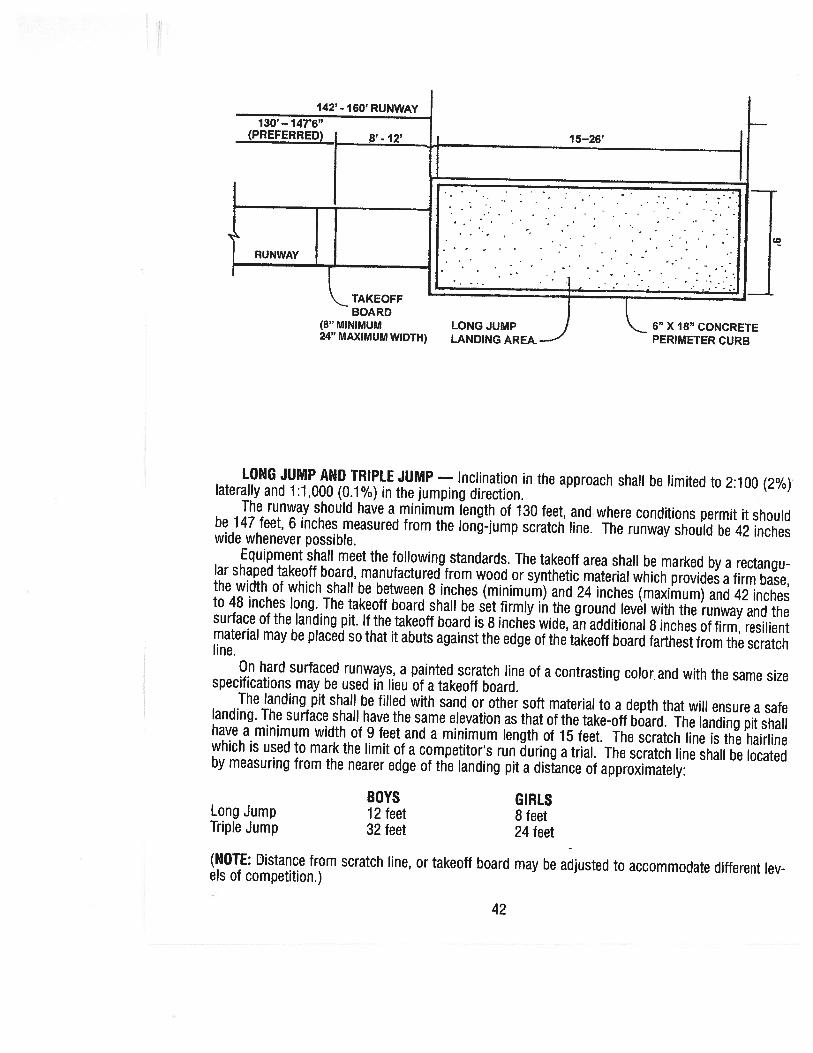
DISCUS — The throwing circle shall be 8 feet, 21/2 inches (2.50 meters) in diameter. The circumference shall be marked with a metal, wood or plastic band which shall not rise more than ¾ inch(1 .9 centimeters) above the level of the circle or if the circle has a surface of asphalt, concrete, woodor other hard material, a painted line 2 inches (5 centimeters) wide may substitute for the band. Theinside edge of the line or band is the limit of the throwing circle.
Projecting lines, 2 inches (5 centimeters) wide and 8 inches (20 centimeters) long, lying on thediameter extended and outside the circumference shall be used to designate the back half of thethrowing circle.
A 34.92-degree sector shall be marked on the ground and drawn from the center of the throwing circle. From the center of the circle, mark one sector line. To establish the other sector line, usethe point of intersection of the first sector line and the inside edge of the throwing circle and strikean arc with a radius of 2 feet, 5/16 inches (75.07 cm), so that it intersects the circle. From the center of the discus circle and through this point, construct the second sector line.
45
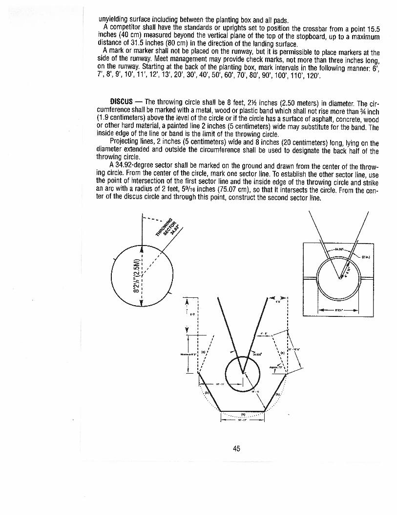
Suggested Discus Cage SpecificationsPortable or permanent installation. it is recommended that the cage be constructed of heavynylon netting or other material that will absorb the energy of the discus to prevent bounce back.Height: lOfeetto 14 feet
Front Opening: 20 feet to 24 feetDistance from Corner Post to Sector Line: 4 feet to 5 feetDistance from Center of Circle to Fencing: 10 feet to 11 feetFencing: Energy-Absorbing Material
(a) 10 feet to 10 feet, 6 inches(b) lOfeetto 11 feet
tOTES:1. The ends of the cage (wing/gate pole) should be placed within 4 to 5 feet of the sector lines.2. The above diagram of a discus throwing cage is designed to provide limited protection for competitors, officials and spectators in the immediate throwing area. Due to the nature of the event, itdoes not ensure the safety of the aforementioned personnel.3. It is recommended that all throwing areas be corded off with rope, fence or flags placed well outside the sector lines to minimize the risk of injury for spectators and athletes.
SHOT PUT — A 34.92-degree sector shall be marked on the ground. The putting circles shallhave an inside diameter of 7 feet (2.134 m). The circumference shall be marked with a metal, woodor plastic band which shall not rise more than 3/4 inch (1 .9 cm) above the level of the circle; or, if thecircle has a surface of asphalt, concrete, wood or other hard material, a painted line 2 inches (5 cm)wide may be substituted for the band. A concrete surface with a 1/64 inch (1 mm) roughness is recommended.A stopboard, constructed of concrete, fiberglass, metal, wood or other hard-surfaced materialin the shape of an arc, so that the inner edge coincides with the inner edge of the circle, shall be firm
ly fixed in this position. It shall be 4 feet (1 .22 meters) in length along the inside surface, 4 inches(10 cm) in height and 41/2 inches (11 .4 cm) in width. The inside edge of the line or band is the limitof the putting circle.Radial lines 2 inches (5 cm) wide shall extend from the center of the circle to form an area intowhich legal puts must be made. The inside edges of these lines shall mark the sector and the linesshall be placed equidistant from the ends of the stopboard.
46

- JAVELIN THROW — The runway for the throw should have a minimum length of 120 feet (36.5meters) and shall be marked by two parallel lines, 13 feet, 1½ inches (4 meters) apart and terminated by a foul-line arc with a radius of 26 feet, 3 inches (8 meters) as shown below. The foul-line arcshall be marked with a white metal, plastic or wood band 2¾ inches (7 centimeters) in width. If usinga band, the top surface shall be level with the throwing surface. The line or band shall be in the throwing sector with the edge toward the runway coinciding with the foul-line arc. A line 2¾ inches (7 centimeters) in width and at least 2 feet, 51/2 inches (75 centimeters) in length shall be placed or painted on each side of the runway perpendicular to the side boundaries at the intersection of the foul-line arc and inside of the side boundary lines.
The throwing sector is that area defined by extending radii through the two intersections of thearc with the runway lines and a point midway between the runway lines and 26 feet, 3 inches (8meters) from the foul line.
413’ 11/2” (4m) THROWING
SECTOR
FOULLINE
47