Embed Size (px)
Citation preview

Revision 13Updated: February 2, 2007
Revisión 13Revisado: February 2, 2007
Información Confidencial y PropietariaEste documento contiene información confidencial y
propietaria de Atlanta Attachment Company. Además de cualquier acuerdo de confidencialidad y de no-divulgación que puedan existir entre usted y Atlanta Attachment Company, el uso de estos materiales por su parte sirve como reconocimiento de la naturaleza confidencial y de propiedad de este material y de su obligación de no hacer ningún uso desautorizado o divulgación de los mismos.
El material aquí contenido está protegido bajo las leyes de derecho de autor de los Estados Unidos y no puede ser utilizado, divulgado, reproducido, distribuido, publicado, o vendido sin el consentimiento explícito escrito de Atlanta Attachment Company, cuyo permiso puede ser negado a discreción de Atlanta Attachment Company. Está estrictamente prohibido quitar o cambiar cualquier aviso de derechos de autor, marca registrada u otros avisos de copias de estos materiales.
Patentes & Patentes PendientesLa venta de este producto no vende ni tampoco
transfiere ninguna licencia o derecho bajo cualquier Patente de los EE UU de América o la patente correspondiente de otro país. Este equipo está protegido bajo una o más de las siguientes patentes: Patentes de EE UU: 4,038,933; 4,280,421; 4,432,294; 4,466,367; 4,644,883; 4,886,005; 5,134,947; 5,159,889; 5,203,270; 5,307,750; 5,373,798; 5,437,238; 5,522,332; 5,524,563; 5,562,060; 5,634,418; 5,647,293; 5,657,711; 5,743,202; 5,865,135; 5,899,159; 5,915,319; 5,918,560; 5,924,376; 5,979,345, 6,035,794 Patentes extranjeras - 2,084,055; 2,076,379; 2,177,389; 2,210,569; 4-504,742; 8-511,916; 9-520,472; 0,537,323; 92,905,522.6; 95,935,082.8; 96,936,922.2; 5,159,889; 5,203,270. Están pendientes otras patentes de los EE UU y otros países.
Atlanta Attachment Company 362 Industrial Park Drive
Lawrenceville, Georgia 30045Phone:(770) 963-7369Fax:(770) 963-7641
Email:[email protected]
© 2003-2007 Atlanta Attachment Company.
Derechos reservados.
Atlanta Attachment Company, Inc.
Confidential And Proprietary InformationThe materials contained herein are confidential and
proprietary information of Atlanta Attachment Company. In addition to any confidentiality and non-disclosure obligations that currently exist between you and Atlanta Attachment Company, your use of these materials serves as an acknowledgment of the confidential and proprietary nature of these materials and your duty not to make any unauthorized use or disclosure of these materials.
All materials contained herein are additionally protected by United States Copyright law and may not be used, disclosed, reproduced, distributed, published or sold without the express written consent of Atlanta Attachment Company, which consent may be withheld in Atlanta Attachment Company’s sole discretion. You may not alter or remove any copyright, trademark or other notice from copies of these materials.
Patents & Patents PendingThe sale of this product does not sell or otherwise
transfer any license or other rights under any U.S. Patent or other corresponding foreign patent.This equipment is protected by one or more of the following patents: US patents:4,038,933; 4,280,421; 4,432,294; 4,466,367; 4,644,883; 4,886,005; 5,134,947; 5,159,889; 5,203,270; 5,307,750; 5,373,798; 5,437,238; 5,522,332; 5,524,563; 5,562,060; 5,634,418; 5,647,293; 5,657,711; 5,743,202; 5,865,135; 5,899,159; 5,915,319; 5,918,560; 5,924,376; 5,979,345, 6,035,794Foreign patents - 2,084,055; 2,076,379; 2,177,389; 2,210,569; 4-504,742; 8-511,916; 9-520,472; 0,537,323; 92,905,522.6; 95,935,082.8; 96,936,922.2; 5,159,889; 5,203,270.Other U.S. and Foreign Patents Pending.
Atlanta Attachment Company 362 Industrial Park Drive
Lawrenceville, Georgia 30045Phone:(770) 963-7369Fax:(770) 963-7641
Email:[email protected]
© 2003-2007 Atlanta Attachment Company.All rights reserved.
!! I M P O R T A N T
It is important to read and understand the information contained within this manual beforeattempting to operate the machine. Atlanta Attachment Co., Inc. shall not be held liable fordamage resulting from misuse of the information presented within, and reserves the right to changethe information contained within, without prior notification.
Es muy importante leer e entender la información contenida en este manual antes de intentaroperar la máquina. La Compañia Atlanta Attachment Co., Inc. no se responsabiliza por ningúndaño que sea resultado del mal uso de la información presentada en este documento y se reserva elderecho de hacer cambios del contenida sin previo aviso al usuario.

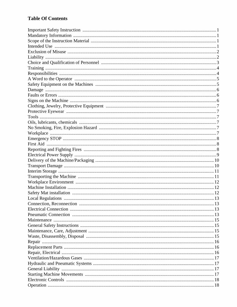
Table Of Contents
Important Safety Instruction ...................................................................................................................1Mandatory Information ...........................................................................................................................1Scope of the Instruction Material ............................................................................................................1Intended Use ...........................................................................................................................................1Exclusion of Misuse ................................................................................................................................2Liability ...................................................................................................................................................2Choice and Qualification of Personnel ...................................................................................................3Training ...................................................................................................................................................4Responsibilities .......................................................................................................................................4A Word to the Operator ..........................................................................................................................5Safety Equipment on the Machines ........................................................................................................5Damage ...................................................................................................................................................6Faults or Errors ........................................................................................................................................6Signs on the Machine ..............................................................................................................................6Clothing, Jewelry, Protective Equipment ...............................................................................................7Protective Eyewear .................................................................................................................................7Tools ........................................................................................................................................................7Oils, lubricants, chemicals ......................................................................................................................7No Smoking, Fire, Explosion Hazard .....................................................................................................7Workplace ...............................................................................................................................................7Emergency STOP ....................................................................................................................................8First Aid ..................................................................................................................................................8Reporting and Fighting Fires ..................................................................................................................8Electrical Power Supply ..........................................................................................................................9Delivery of the Machine/Packaging ......................................................................................................10Transport Damage .................................................................................................................................10Interim Storage ......................................................................................................................................11Transporting the Machine .....................................................................................................................11Workplace Environment .......................................................................................................................12Machine Installation ..............................................................................................................................12Safety Mat installation ..........................................................................................................................12Local Regulations .................................................................................................................................13Connection, Reconnection ....................................................................................................................13Electrical Connection ............................................................................................................................13Pneumatic Connection ..........................................................................................................................13Maintenance ..........................................................................................................................................15General Safety Instructions ...................................................................................................................15Maintenance, Care, Adjustment ............................................................................................................15Waste, Disassembly, Disposal ..............................................................................................................15Repair ....................................................................................................................................................16Replacement Parts .................................................................................................................................16Repair, Electrical ...................................................................................................................................16Ventilation/Hazardous Gases ................................................................................................................17Hydraulic and Pneumatic Systems ........................................................................................................17General Liability ...................................................................................................................................17Starting Machine Movements ...............................................................................................................17Electronic Controls ...............................................................................................................................18Operation ...............................................................................................................................................18
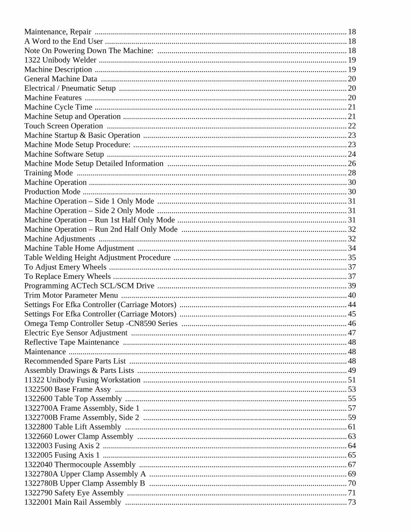
Maintenance, Repair ............................................................................................................................. 18A Word to the End User ........................................................................................................................ 18Note On Powering Down The Machine: .............................................................................................. 181322 Unibody Welder ........................................................................................................................... 19Machine Description ............................................................................................................................. 19General Machine Data .......................................................................................................................... 20Electrical / Pneumatic Setup ................................................................................................................. 20Machine Features .................................................................................................................................. 20Machine Cycle Time ............................................................................................................................. 21Machine Setup and Operation ............................................................................................................... 21Touch Screen Operation ....................................................................................................................... 22Machine Startup & Basic Operation ..................................................................................................... 23Machine Mode Setup Procedure: .......................................................................................................... 23Machine Software Setup ....................................................................................................................... 24Machine Mode Setup Detailed Information ......................................................................................... 26Training Mode ...................................................................................................................................... 28Machine Operation ................................................................................................................................ 30Production Mode ................................................................................................................................... 30Machine Operation – Side 1 Only Mode .............................................................................................. 31Machine Operation – Side 2 Only Mode .............................................................................................. 31Machine Operation – Run 1st Half Only Mode .................................................................................... 31Machine Operation – Run 2nd Half Only Mode .................................................................................. 32Machine Adjustments ........................................................................................................................... 32Machine Table Home Adjustment ........................................................................................................ 34Table Welding Height Adjustment Procedure ...................................................................................... 35To Adjust Emery Wheels ...................................................................................................................... 37To Replace Emery Wheels .................................................................................................................... 37Programming ACTech SCL/SCM Drive .............................................................................................. 39Trim Motor Parameter Menu ................................................................................................................ 40Settings For Efka Controller (Carriage Motors) ................................................................................... 44Settings For Efka Controller (Carriage Motors) ................................................................................... 45Omega Temp Controller Setup -CN8590 Series .................................................................................. 46Electric Eye Sensor Adjustment ........................................................................................................... 47Reflective Tape Maintenance ............................................................................................................... 48Maintenance .......................................................................................................................................... 48Recommended Spare Parts List ............................................................................................................ 48Assembly Drawings & Parts Lists ........................................................................................................ 4911322 Unibody Fusing Workstation ..................................................................................................... 511322500 Base Frame Assy ................................................................................................................... 531322600 Table Top Assembly .............................................................................................................. 551322700A Frame Assembly, Side 1 ..................................................................................................... 571322700B Frame Assembly, Side 2 ..................................................................................................... 591322800 Table Lift Assembly .............................................................................................................. 611322660 Lower Clamp Assembly ........................................................................................................ 631322003 Fusing Axis 2 ......................................................................................................................... 641322005 Fusing Axis 1 ......................................................................................................................... 651322040 Thermocouple Assembly ....................................................................................................... 671322780A Upper Clamp Assembly A .................................................................................................. 691322780B Upper Clamp Assembly B .................................................................................................. 701322790 Safety Eye Assembly ............................................................................................................. 711322001 Main Rail Assembly .............................................................................................................. 73

1322100 Fusing Head Assembly ...........................................................................................................751322021 Carriage 1 Assembly ..............................................................................................................771322006 Carriage 2 Assembly ..............................................................................................................791322140 Leister Gun Assembly ............................................................................................................801322130 Blade Sharpener .....................................................................................................................811322830 Panel Sensor Assembly ..........................................................................................................831322831 Panel Sensor Assembly ..........................................................................................................851322-PD1 Pneumatic Diagram ..............................................................................................................861322-WD1A Wiring Diagram ...............................................................................................................871322-WD2 Wiring Diagram ..................................................................................................................88
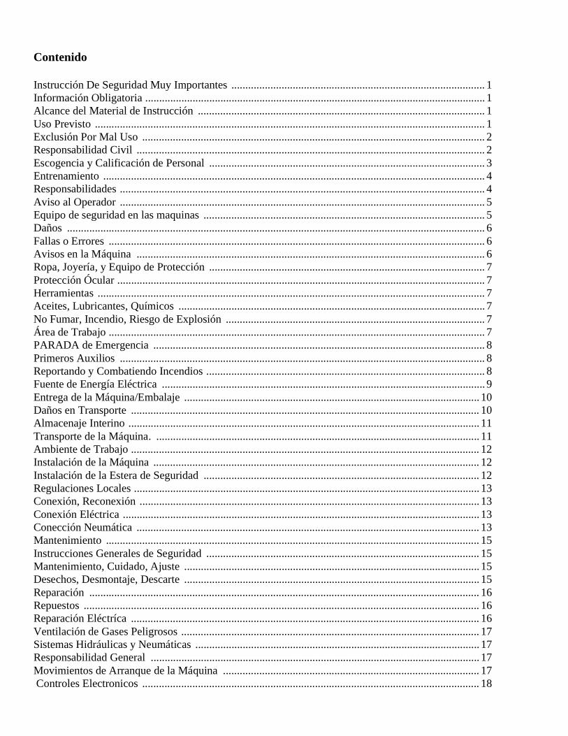
Contenido
Instrucción De Seguridad Muy Importantes ........................................................................................... 1Información Obligatoria .......................................................................................................................... 1Alcance del Material de Instrucción ....................................................................................................... 1Uso Previsto ............................................................................................................................................ 1Exclusión Por Mal Uso ........................................................................................................................... 2Responsabilidad Civil ............................................................................................................................. 2Escogencia y Calificación de Personal ................................................................................................... 3Entrenamiento ......................................................................................................................................... 4Responsabilidades ................................................................................................................................... 4Aviso al Operador ................................................................................................................................... 5Equipo de seguridad en las maquinas ..................................................................................................... 5Daños ...................................................................................................................................................... 6Fallas o Errores ....................................................................................................................................... 6Avisos en la Máquina ............................................................................................................................. 6Ropa, Joyería, y Equipo de Protección ................................................................................................... 7Protección Ócular .................................................................................................................................... 7Herramientas ........................................................................................................................................... 7Aceites, Lubricantes, Químicos .............................................................................................................. 7No Fumar, Incendio, Riesgo de Explosión ............................................................................................. 7Área de Trabajo ....................................................................................................................................... 7PARADA de Emergencia ....................................................................................................................... 8Primeros Auxilios ................................................................................................................................... 8Reportando y Combatiendo Incendios .................................................................................................... 8Fuente de Energía Eléctrica .................................................................................................................... 9Entrega de la Máquina/Embalaje .......................................................................................................... 10Daños en Transporte ............................................................................................................................. 10Almacenaje Interino .............................................................................................................................. 11Transporte de la Máquina. .................................................................................................................... 11Ambiente de Trabajo ............................................................................................................................. 12Instalación de la Máquina ..................................................................................................................... 12Instalación de la Estera de Seguridad ................................................................................................... 12Regulaciones Locales ............................................................................................................................ 13Conexión, Reconexión .......................................................................................................................... 13Conexión Eléctrica ................................................................................................................................ 13Conección Neumática ........................................................................................................................... 13Mantenimiento ...................................................................................................................................... 15Instrucciones Generales de Seguridad .................................................................................................. 15Mantenimiento, Cuidado, Ajuste .......................................................................................................... 15Desechos, Desmontaje, Descarte .......................................................................................................... 15Reparación ............................................................................................................................................ 16Repuestos .............................................................................................................................................. 16Reparación Eléctríca ............................................................................................................................. 16Ventilación de Gases Peligrosos ........................................................................................................... 17Sistemas Hidráulicas y Neumáticas ...................................................................................................... 17Responsabilidad General ...................................................................................................................... 17Movimientos de Arranque de la Máquina ............................................................................................ 17 Controles Electronicos ......................................................................................................................... 18
Operación ..............................................................................................................................................18Mantenimiento, Reparación ..................................................................................................................18Aviso al Usuário ....................................................................................................................................18Aviso importante antes de apagar la máquina: .....................................................................................181322 .......................................................................................................................................................19Máquina de Soldadura Integral Detalles de la Maquina de Soldar .......................................................19Datos Generales de la Máquina .............................................................................................................20Instalación Electrica/Neumática ............................................................................................................20Características de la Máquina ...............................................................................................................20Tiempo de Ciclo de la Máquina ............................................................................................................21Instalación y Operación de la Máquina .................................................................................................21Operación de la Pantalla Táctil .............................................................................................................22Encendido de la Máquina & Operación Básica ....................................................................................23Modalidad de la Máquina: ....................................................................................................................23Configuración del Programa de la Máquina .........................................................................................24Configuración de las Modalidades de la Máquina ................................................................................26Entrenamiento .......................................................................................................................................28Operación de la Máquina ......................................................................................................................30Producción .............................................................................................................................................30Operación de la Máquina - Lado 1 Solamente ......................................................................................31Operación de la Máquina - Lado 2 Solamente ......................................................................................31Operación de la Máqina - Primera Mitad Solamente ............................................................................32Operación de la Máqina - Segunda Mitad Solamente ...........................................................................32Ajustes de la Máquina ...........................................................................................................................32Ajuste de la Altura de la Mesa de Soldadura ........................................................................................35Ajuste del Posición Inicial de la Mesa ..................................................................................................34Ajuste de los Esmeriles .........................................................................................................................37Para Reemplazar los Esmeriles .............................................................................................................37Programación de la Caja ACTech SCL/SCM .......................................................................................39Menú de parámetros del Motor de Recorte ...........................................................................................42Configuraciones para el Controlador Efka (Motores de los Carros) .....................................................44Configuración del Controlador de Temperatura Omega Serie CN8590 ..............................................46Ajuste del Sensor Óptico .......................................................................................................................47Mantenimiento de la Cinta Reflectiva ...................................................................................................48Mantenimiento ......................................................................................................................................48Lista de Repuestos Recomendados .......................................................................................................48Lista De Partes ......................................................................................................................................4911322 Unibody Fusing Workstation .....................................................................................................511322500 Base Frame Assy ....................................................................................................................531322600 Table Top Assembly ..............................................................................................................551322700A Frame Assembly, Side 1 ......................................................................................................571322700B Frame Assembly, Side 2 ......................................................................................................591322800 Table Lift Assembly ...............................................................................................................611322660 Lower Clamp Assembly .........................................................................................................631322003 Fusing Axis 2 .........................................................................................................................641322005 Fusing Axis 1 .........................................................................................................................651322040 Thermocouple Assembly .......................................................................................................671322780A Upper Clamp Assembly A ..................................................................................................691322780B Upper Clamp Assembly B ...................................................................................................701322790 Safety Eye Assembly .............................................................................................................711322001 Main Rail Assembly ...............................................................................................................73

1322100 Fusing Head Assembly .......................................................................................................... 751322021 Carriage 1 Assembly .............................................................................................................. 771322006 Carriage 2 Assembly .............................................................................................................. 791322140 Leister Gun Assembly ........................................................................................................... 801322130 Blade Sharpener ..................................................................................................................... 811322830 Panel Sensor Assembly .......................................................................................................... 831322831 Panel Sensor Assembly .......................................................................................................... 851322-PD1 Pneumatic Diagram ............................................................................................................. 861322-WD1A Wiring Diagram .............................................................................................................. 871322-WD2 Wiring Diagram ................................................................................................................. 88
Important Safety Instruction
Important Safety Instruction
This part of the Instruction Material is provided for the safe use of your equipment. It contains important inpormation to help work safely with your machine and descrice the dangers inherent in machinery. Some of these dangers are obvious, while others are less evident.
Mandatory InformationAll persons working on the machine should read and understand all parts of the Safety Instructions. This applies, in particular, for persons who only work on the machine occasionally (e.g. for maintenance and repair). Persons who have difficulty reading must receive particularly thorough instruction.
Scope of the Instruction MaterialThe Instruction Material comprises:
• Safety information,• Operator Instructions,• Electrical and Pneumatic diagrams, and may also include;• A list of recommended spare parts,• Serial Bus Control system Operator instructions,• Instruction Manual(s) for components made by other manufacturers and• The layout and installation diagram containing information for installation.
Intended UseOur machines are designed and built in line with the state of the art and the accepted safety rules. However, all machines may endanger the life and limb of their users and/or third parties and be damaged or cause damage to other property, particularly if they are operated incorrectly or used for purposes other than those specified in the Instruction Manual.
1322 Technical Manual
1
Instrucción De Seguridad Muy Importantes
Esta parte del Manual de Instrucción está proporcionado para el uso seguro de su máquina. Contiene información importante para facilitar la operación segura de su máquina e indicar los peligros de operación de equipos mecánicos. Algunos de los peligros son obvios mientras otros existen
que no son tan evidentes.
Información ObligatoriaCualquier persona que trabaja con la máquina debe leer e entender todas las partes del Manual de Seguridad. Este es de suma importancia para las personas que solamente hacen uso de la máquina de vez en cuando (por ejemplo personal de
mantenimiento y reparación). Es obligatorio que cualquier persona que tiene dificultad para leer reciba instrucción particula.
Alcance del Material de InstrucciónLos Materiales de Instrucción incluye:
• Información de seguridad, • Instrucciones de operación, • Diagramas eléctricos y neumáticos, y además puede incluir;• Una lista de repuestos recomendados, • Instrucciones de operación del sistema de control "Bus Serie", • Manuales de instrucción para componentes de otros fabricantes y• El plano y diagrama de instalación que contiene información de instalación.
Uso Previsto Hemos diseñado y construido nuestras máquinas de acuerdo con la última tecnología y las últimas reglas de seguridad. Sin embargo cualquier máquina puede poner en peligro la vida y miembro del cuerpo de los operadores y/o terceros y pueden ser dañados o causar daños a otra propiedad, particularmente si se opera de manera incorrecta o si se usa para otros motivos de los que se especifican in el Manual de Instrucció
2
Important Safety InstructionExclusión Por Mal UsoEl mal uso del equipo incluye, por ejemplo, su uso con motivos distintos de los para que fuera diseñado, y además su operación sin la instalación correcta de equipos de seguridad. El riesgo queda últimamente con el usuario final.
El uso correcto del equipo incluye la conformidad con los datos técnicos, información y regulaciones de los Materiales de Instrucción en su totalidad y la conformidad con las regulaciones de mantenimiento. También se debe observar y seguir todas las reglas locales de seguridad y prevención de accidentes.
Responsabilidad CivilSe debe operar la máquina solamente cuando esté en perfectas condiciones de funcionamiento, con la debida atención a la seguridad y peligros potenciales, y en acuerdo con el Material de Instrucción. Fallas y desperfectos capaces de perjudicar la seguridad deben ser reparados de inmediato. No podemos aceptar cualquier responsabilidad civil que resulta de herida personal o daños a propiedad las cuales son el resultado del descuido del operador o por causa de no conformar con las instrucciones de seguridad contenidas en este manual. El último usuario se responsabiliza exclusivamente por cualquier riesgo.
Exclusion of MisuseNon-conforming uses include, for example, using the equipment for something other than it was designed for, as well as operation without duly installed safety equipment. The risk rests exclusively with the end user.
Conforming use of the machine includes compliance with the technical data, information and regulations in all parts of the complete Instruction Material, as well as compliance with the maintenance regulations. All local safety and accident prevention regulations must also be observed.
LiabilityThe machine should only be operated when in perfect working order, with due regard for safety and the potential dangers, as well as in accordance with the Instruction Material. Faults and malfunctions capable of impairing safety should be remedied immediately. We cannot accept any liability for personal injury or property damage due to operator errors or non-compliance with the safety instructions contained in this booklet. The risk rests exclusively with the end user.
1322 Technical Manual
Important Safety Instruction
The Instruction Material should always be kept near the machine so that it is accessible to all concerned.The local, general, statutory, and other binding regulations on accident prevention and environmental protection must also be observed in addition to the Instruction Material. The operating staff must be instructed accordingly. This obligation also includes the handling of dangerous substances and provision/use of personal protective equipment.
The Instruction Material should be supplemented by instructions, including supervisory and notification duties with due regard for special operational features, such as the organization of work, work sequences, the personnel deployed, etc.
The personnel's awareness of the dangers and compliance with the safety regulations should be checked at irregular intervals.
Choice and Qualification of PersonnelEnsure that work on the machine is only carried out by reliable persons who have been appropriately trained for such work - either within the company, by our field staff or at our office - and who have not only been duly appointed and authorized, but are also fully familiar with the local regulations. Work on the machine should only be carried out by skilled personnel, under the management and supervision of a duly qualified engineer.
This not only applies when the machine is used for production, but also for special work associated with its operation (start-up and maintenance), especially when it concerns work on the pneumatic or electrical systems, as well as on the software/serial bus system.
1322 Technical Manual
3
Las Instrucciones de Seguridad siempre deben mantenerse cerca de la máquina para que sea accesible a cualquier usuario o interesado.
Las reglas locales, generales, estatuarias o cualquier reglamento obligatorio sobre prevención de accidentes y la protección del medio ambiente deben ser observados además del Material de Instrucción. Se debe dar la instrucción debida al cuerpo de operadores. Esta obligación también incluye instrucción sobre el manejo de sustancias peligrosas y el uso y provisión de equipo de protección personal.
El Material de Instrucción se de complementar con instrucciones, incluyendo notas a supervisores y notificación de obligaciones con referencia especifica a operaciones especiales como organización de trabajo, secuencia de trabajos, personal utilizado, etc.
La atención del personal a los peligros y cumplimiento con las reglas de seguridad deben ser revisados con regularidad.
Escogencia y Calificación de PersonalEs sumamente importante que la operación de la máquina sea realizada solamente por personas confiables que han sido entrenadas para ejecutar tal trabajo - o dentro de la empresa, por nuestros técnicos o en nuestras instalaciones - y quienes no solamente han sido seleccionados y autorizados pero también conocen los reglamentos locales. Cualquier trabajo que se realice en la máquina deber ser llevado a cabo solamente por personal capacitado y bajo la supervisión de un ingeniero calificado.
Esto no solo se refiere a cuando la máquina sea utilizada para trabajo de producción, pero también para cualquier trabajo asociado con su operación (de arranque y mantenimiento), especialmente cuando se trata de los sistemas eléctricos y neumáticos o en el sistema de "Bus Serie".
4
Important Safety InstructionEntrenamientoToda personal que trabaja con la máquina debe recibir el entrenamiento debido y estar informado en referencia del uso correcto de equipo de seguridad personal, y los peligros que pueden suceder durante la operación del equipo y las precauciones que se deben
tomar. Adicionalmente se debe instruir el personal sobre la importancia de revisión de los mecanismos de seguridad con regularidad.
ResponsabilidadesHay que definir con claridad quienes son los responsables para la operación, montaje, servicio y reparación de la máquina. Detalle las responsabilidades del operador de la máquina y dele la autorización para rehusar cualquier instrucción de terceros si las instrucciones van contrarias al manejo seguridad de la máquina. Esto se aplica particularmente a los operadores de máquinas operadas en conjunción con otras máquinas. Personas que reciben entrenamiento de cualquier clase solamente deben trabajar bajo la constante supervisión de un operador experimentado. Ponga atención a los reglamentos de edad mínima de operadores que se permite la ley.
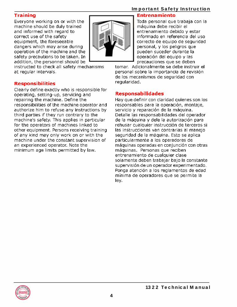
TrainingEveryone working on or with the machine should be duly trained and informed with regard to correct use of the safety equipment, the foreseeable dangers which may arise during operation of the machine and the safety precautions to be taken. In addition, the personnel should be instructed to check all safety mechanisms at regular intervals.
ResponsibilitiesClearly define exactly who is responsible for operating, setting-up, servicing and repairing the machine. Define the responsibilities of the machine operator and authorize him to refuse any instructions by third parties if they run contrary to the machine's safety. This applies in particular for the operators of machines linked to other equipment. Persons receiving training of any kind may only work on or with the machine under the constant supervision of an experienced operator. Note the minimum age limits permitted by law.
1322 Technical Manual
Important Safety Instruction
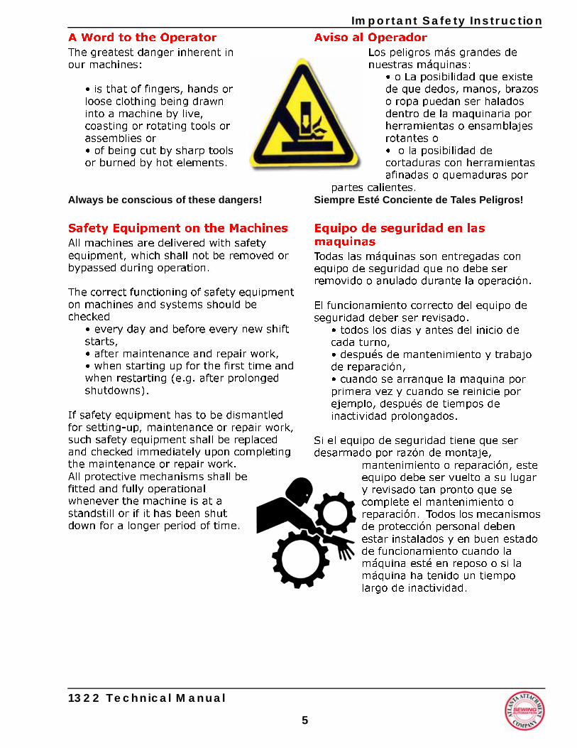
A Word to the OperatorThe greatest danger inherent in our machines:
• is that of fingers, hands or loose clothing being drawn into a machine by live, coasting or rotating tools or assemblies or • of being cut by sharp tools or burned by hot elements.
Always be conscious of these dangers!
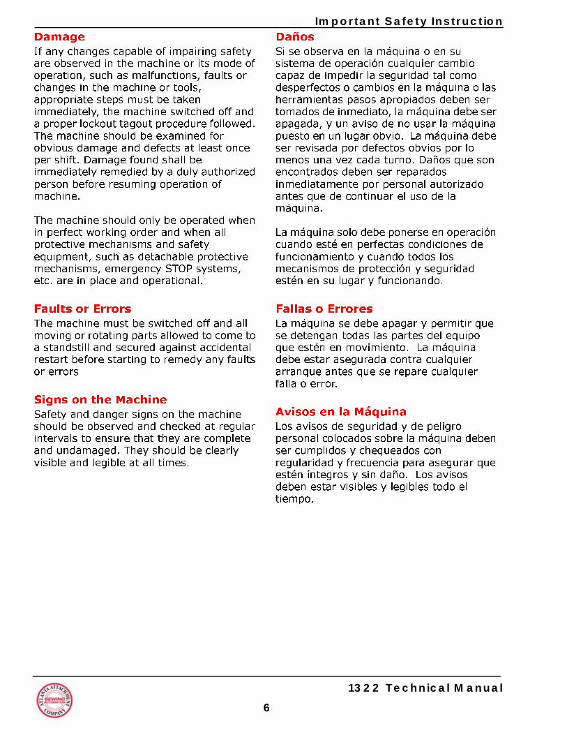
Safety Equipment on the MachinesAll machines are delivered with safety equipment, which shall not be removed or bypassed during operation.
The correct functioning of safety equipment on machines and systems should be checked
• every day and before every new shift starts, • after maintenance and repair work, • when starting up for the first time and when restarting (e.g. after prolonged shutdowns).
If safety equipment has to be dismantled for setting-up, maintenance or repair work, such safety equipment shall be replaced and checked immediately upon completing the maintenance or repair work. All protective mechanisms shall be fitted and fully operational whenever the machine is at a standstill or if it has been shut down for a longer period of time.
1322 Technical Manual
5
Aviso al OperadorLos peligros más grandes de nuestras máquinas:
• o La posibilidad que existe de que dedos, manos, brazos o ropa puedan ser halados dentro de la maquinaria por herramientas o ensamblajes rotantes o• o la posibilidad de cortaduras con herramientas afinadas o quemaduras por
partes calientes. Siempre Esté Conciente de Tales Peligros!
Equipo de seguridad en las maquinasTodas las máquinas son entregadas con equipo de seguridad que no debe ser removido o anulado durante la operación.
El funcionamiento correcto del equipo de seguridad deber ser revisado.
• todos los dias y antes del inicio de cada turno, • después de mantenimiento y trabajo de reparación, • cuando se arranque la maquina por primera vez y cuando se reinicie por ejemplo, después de tiempos de inactividad prolongados.
Si el equipo de seguridad tiene que ser desarmado por razón de montaje,
mantenimiento o reparación, este equipo debe ser vuelto a su lugar y revisado tan pronto que se complete el mantenimiento o reparación. Todos los mecanismos de protección personal deben estar instalados y en buen estado de funcionamiento cuando la máquina esté en reposo o si la máquina ha tenido un tiempo largo de inactividad.
6
Important Safety InstructionDañosSi se observa en la máquina o en su sistema de operación cualquier cambio capaz de impedir la seguridad tal como desperfectos o cambios en la máquina o las herramientas pasos apropiados deben ser tomados de inmediato, la máquina debe ser apagada, y un aviso de no usar la máquina puesto en un lugar obvio. La máquina debe ser revisada por defectos obvios por lo menos una vez cada turno. Daños que son encontrados deben ser reparados inmediatamente por personal autorizado antes que de continuar el uso de la máquina.
La máquina solo debe ponerse en operación cuando esté en perfectas condiciones de funcionamiento y cuando todos los mecanismos de protección y seguridad estén en su lugar y funcionando.
Fallas o ErroresLa máquina se debe apagar y permitir que se detengan todas las partes del equipo que estén en movimiento. La máquina debe estar asegurada contra cualquier arranque antes que se repare cualquier falla o error.
Avisos en la Máquina Los avisos de seguridad y de peligro personal colocados sobre la máquina deben ser cumplidos y chequeados con regularidad y frecuencia para asegurar que estén íntegros y sin daño. Los avisos deben estar visibles y legibles todo el tiempo.
DamageIf any changes capable of impairing safety are observed in the machine or its mode of operation, such as malfunctions, faults or changes in the machine or tools, appropriate steps must be taken immediately, the machine switched off and a proper lockout tagout procedure followed. The machine should be examined for obvious damage and defects at least once per shift. Damage found shall be immediately remedied by a duly authorized person before resuming operation of machine.
The machine should only be operated when in perfect working order and when all protective mechanisms and safety equipment, such as detachable protective mechanisms, emergency STOP systems, etc. are in place and operational.
Faults or ErrorsThe machine must be switched off and all moving or rotating parts allowed to come to a standstill and secured against accidental restart before starting to remedy any faults or errors
Signs on the MachineSafety and danger signs on the machine should be observed and checked at regular intervals to ensure that they are complete and undamaged. They should be clearly visible and legible at all times.
1322 Technical Manual
Important Safety Instruction
Clothing, Jewelry, Protective EquipmentLong loose hair, loose-fitting clothes, gloves and jewelry, including rings, should be avoided in order to avoid injuries due to being caught, drawn in and wound up inside the machine.
Protective EyewearProtective eyewear that has been tested by the local authorities should be worn whenever there is a possibility of loose or flying objects or particles such as when cleaning the machine with compressed air.
ToolsAlways count the number of tools in your possession before starting work on the machine. This will allow you to check that no tools have been left behind inside the machine. Never leave a tool in the machine while working.
Oils, lubricants, chemicalsNote the applicable safety regulations for the product used.
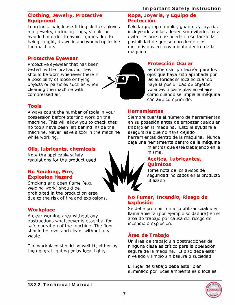
No Smoking, Fire, Explosion HazardSmoking and open flame (e.g. welding work) should be prohibited in the production area due to the risk of fire and explosions.
WorkplaceA clear working area without any obstructions whatsoever is essential for safe operation of the machine. The floor should be level and clean, without any waste.
The workplace should be well lit, either by the general lighting or by local lights.
1322 Technical Manual
7
Ropa, Joyería, y Equipo de ProtecciónPelo largo, ropa amplia, guantes y joyería, incluyendo anillos, deben ser evitados para evitar lesiones que pueden resultar de la posibilidad de que se enreden en los mecanismos en movimiento dentro de la máquina.
Protección ÓcularSe debe usar protección para los ojos que haya sido aprobada por las autoridades locales cuando haya la posibilidad de objetos volantes o partículas en el aire como cuando se limpia la máquina con aire comprimido.
HerramientasSiempre cuente el número de herramientas en su posesión antes de empezar cualquier trabajo en la máquina. Esto le ayudara a asegurarse que no haya dejado herramientas dentro de la máquina. Nunca deje una herramienta dentro de la máquina
mientras que esté trabajando en la misma.
Aceites, Lubricantes, QuímicosTome nota de los avisos de seguridad indicados en el producto utilizado.
No Fumar, Incendio, Riesgo de Explosión Se debe prohibir fumar o utilizar cualquier llama abierta (por ejemplo soldadura) en el área de trabajo por causa del riesgo de incendio o explosión.
Área de TrabajoUn área de trabajo sin obstrucciones de ninguna clase es crítico para la operación segura de la máquina. El piso debe estar nivelado y limpio sin basura o suciedad.
El lugar de trabajo debe estar bien iluminado por luces ambientales o locales.
8
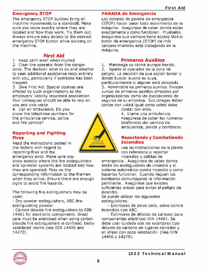
First AidPARADA de EmergenciaLos botones de parada de emergencia (STOP) hacen parar todo movimiento de la máquina. Asegúrese de saber donde están exactamente y como funcionan. Pruébelos. Asegúrese que siempre tiene acceso fácil al botón de emergencia (STOP) de más cercano mientras está trabajando en la máquina.
Primeros Auxilios1. Mantenga su calma aunque herido. 2. Aparte el operador de la zona de peligro. La decisión de que acción tomar y donde buscar auxilio es suya, particularmente si alguien está atrapado.3. Administre los primeros auxilios. Existen cursos de primeros auxilios ofrecidos por organizaciones como las asociaciones de seguros de su empresa. Sus colegas deben contar con usted igual como usted debe
contar con ellos.4. Llame una ambulancia. Asegúrese de saber los números telefónicos del servicio de ambulancia, policía y bomberos.
Reportando y Combatiendo IncendiosLea las instrucciones de la planta con referencia a reportar incendios y salidas de
emergencia. Asegúrese de saber donde están los extinguidotes de incendio y el sistema automático contra incendio y como hacerlos funcionar. Cuando lleguen los bomberos comuníqueles la información pertinente. Asegúrese que existen suficientes avisos para evitar el peligro de incendio.Se puede utilizar los siguientes extinguidores:
- Extintores de polvo seco, polvo contra incendios tipo ABC.
- Extintores de dióxido de carbono para componentes eléctricos DIN 14461. Se debe usar cuidado con los extintores tipo dióxido de carbono en lugares cerrados y en áreas con poca ventilación. (Vea DIN 14406 y 14270).
Emergency STOPThe emergency STOP buttons bring all machine movements to a standstill. Make sure you know exactly where they are located and how they work. Try them out. Always ensure easy access to the nearest emergency STOP button while working on the machine.
First Aid1. Keep calm even when injured. 2. Clear the operator from the danger zone. The decision what to do and whether to seek additional assistance rests entirely with you, particularly if someone has been trapped. 3. Give First Aid. Special courses are offered by such organizations as the employers' liability insurance association. Your colleagues should be able to rely on you and vice versa. 4. Call an ambulance. Do you know the telephone numbers for the ambulance service, police and fire service?
Reporting and Fighting Fires Read the instructions posted in the factory with regard to reporting fires and the emergency exits. Make sure you know exactly where the fire extinguishers and sprinkler systems are located and how they are operated. Pass on the corresponding information to the firemen when they arrive. Ensure there are enough signs to avoid fire hazards.
The following fire extinguishers may be used:- Dry powder extinguishers, ABC fire-extinguishing powder.- Carbon dioxide fire extinguishers to DIN 14461 for electronic components. Great care must be exercised when using carbon dioxide fire extinguishers in confined, badly ventilated rooms (see DIN 14406 and 14270).
1322 Technical Manual
First Aid
Isolate the machine from the power supply if a fire breaks out. Do not use water on burning electrical parts until it is absolutely certain that they have been completely disconnected from the power supply. Burning oils, lubricants, plastics and coatings on the machine can give off gases and vapors that may be harmful to your health. A qualified person should be consulted to repair the damage after a fire.
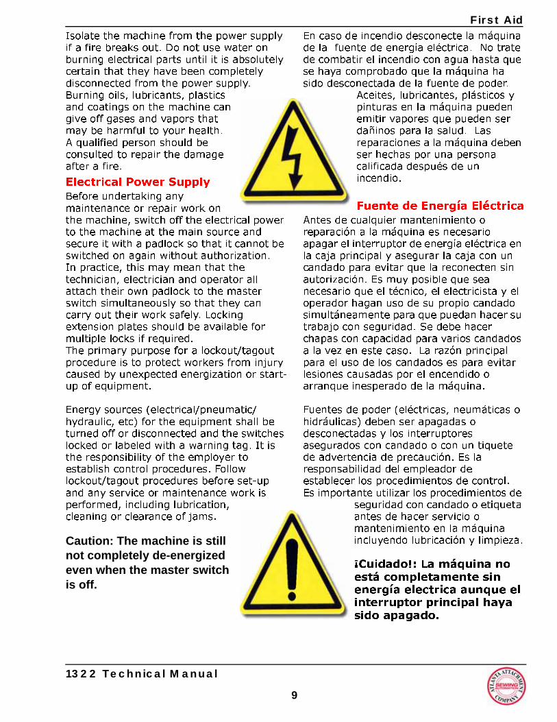
Electrical Power Supply Before undertaking any maintenance or repair work on the machine, switch off the electrical power to the machine at the main source and secure it with a padlock so that it cannot be switched on again without authorization. In practice, this may mean that the technician, electrician and operator all attach their own padlock to the master switch simultaneously so that they can carry out their work safely. Locking extension plates should be available for multiple locks if required. The primary purpose for a lockout/tagout procedure is to protect workers from injury caused by unexpected energization or start-up of equipment.
Energy sources (electrical/pneumatic/hydraulic, etc) for the equipment shall be turned off or disconnected and the switches locked or labeled with a warning tag. It is the responsibility of the employer to establish control procedures. Follow lockout/tagout procedures before set-up and any service or maintenance work is performed, including lubrication, cleaning or clearance of jams.
Caution: The machine is still not completely de-energized even when the master switch is off.
1322 Technical Manual
9
En caso de incendio desconecte la máquina de la fuente de energía eléctrica. No trate de combatir el incendio con agua hasta que se haya comprobado que la máquina ha sido desconectada de la fuente de poder.
Aceites, lubricantes, plásticos y pinturas en la máquina pueden emitir vapores que pueden ser dañinos para la salud. Las reparaciones a la máquina deben ser hechas por una persona calificada después de un incendio.
Fuente de Energía EléctricaAntes de cualquier mantenimiento o reparación a la máquina es necesario apagar el interruptor de energía eléctrica en la caja principal y asegurar la caja con un candado para evitar que la reconecten sin autorización. Es muy posible que sea necesario que el técnico, el electricista y el operador hagan uso de su propio candado simultáneamente para que puedan hacer su trabajo con seguridad. Se debe hacer chapas con capacidad para varios candados a la vez en este caso. La razón principal para el uso de los candados es para evitar lesiones causadas por el encendido o arranque inesperado de la máquina.
Fuentes de poder (eléctricas, neumáticas o hidráulicas) deben ser apagadas o desconectadas y los interruptores asegurados con candado o con un tiquete de advertencia de precaución. Es la responsabilidad del empleador de establecer los procedimientos de control. Es importante utilizar los procedimientos de
seguridad con candado o etiqueta antes de hacer servicio o mantenimiento en la máquina incluyendo lubricación y limpieza.
¡Cuidado!: La máquina no está completamente sin energía electrica aunque el interruptor principal haya sido apagado.
10
First Aid-Electricidad - La máquina está desconectada de la fuente de energía eléctrica cuando el interruptor principal ha sido desconectado. Sin embargo esto no se aplica a la fuente de poder en la caja de control ni tampoco a los equipos que no se alimentan por medio del interruptor principal.
-Energía neumática / hidráulica - Prácticamente todas nuestras máquinas llevan aire comprimido. Además de desconectar el interruptor eléctrico la fuente de aire comprimido debe ser apagada y la máquina revisada para asegurar que no lleva aire bajo presión antes de hacer cualquier trabajo en la máquina. Caso contrario la máquina puede ejecutar funciones no solicitadas.
- Energía Cinética - Note que algunos de los motores o ejes, pueden continuar rotando después de que se ha apagado la fuente de energía
- Energía Potencial - Puede ser que algunos montajes individuales tienen que ser asegurados en caso de reparación de la máquina.
Entrega de la Máquina/EmbalajeTome nota de las indicaciones sobre el embalaje tal como peso, punto de soporte y otra información especial. Evite grandes cambios en temperatura lo cual puede producir condensación que puede dañar la máquina.
Daños en TransporteEs imperativo que hace una inspección del embalaje y la máquina buscando señas de daños que hayan ocurrido en tránsito. Todo daño debe ser reportado a la empresa de transporte dentro del tiempo indicado. Contacte a nuestra oficina o la oficina de su compañía de seguros sin demora. Nunca ponga a funcionar una máquina que ha recibido daños en camino.
- Electricity - The machine is always isolated from the electrical power supply whenever the master switch has been switched off. However, this does not apply for the power supply in the control cabinet, nor for equipment that does not draw its power via the master switch.
- Pneumatic / hydraulic energy - Almost all our machines carry compressed air. In addition to switching off the master switch, the air supply must also be disconnected and the machine checked to ensure it is depressurized before starting any work on the machine; otherwise the machine may execute uncontrolled movements. - Kinetic energy - Note that some motors or spindles, for example, may continue to run or coast run on after being switched off.
- Potential energy - Individual assemblies may need to be secured if necessary for repair work.
Delivery of the Machine/PackagingNote any markings on the packaging, such as weights, lifting points and special information. Avoid temperature fluctuations. Condensation may damage the machine.
Transport DamageThe packaging and machine must immediately be examined for signs of damage in transit. Such damage must be reported to the shipper/transporter within the applicable time limits. Contact us and/or your transport insurer without delay. Never operate a damaged machine.
1322 Technical Manual
First Aid
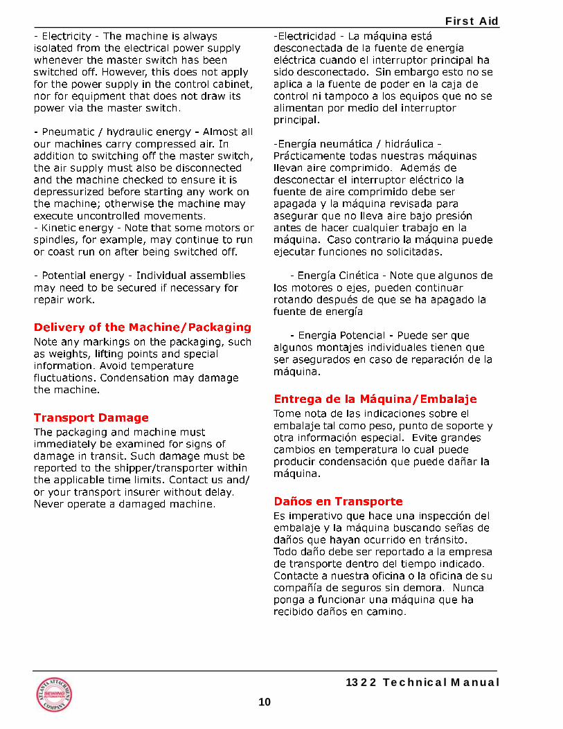
Interim StorageIf the machine has to be stored temporarily, it must be oiled or greased and stored in a dry place where it is protected from the weather in order to avoid damage. A corrosion-inhibiting coating should be applied if the machine has to be stored for a longer period of time and additional precautions taken to avoid corrosion.Transporting the MachineDisconnect the machine from all external connections and secure any loose assemblies or parts. Never step under a suspended load. When transporting the machine or assemblies in a crate, ensure that the ropes or arms of a forklift truck are positioned as close to the edge of the crate as possible. The center of gravity is not necessarily in the middle of the crate. Note the accident prevention regulations, safety instructions and local regulations governing transport of the machine and its assemblies.
Only use suitable transport vehicles, hoisting gear and load suspension devices that are in perfect working order and of adequate carrying capacity. Transport should only be entrusted to duly qualified personnel.
Never allow the straps to rest against the machine enclosure and never push or pull sensitive parts of the machine. Ensure that the load is always properly secured. Before or immediately after loading the machine, secure it properly and affix corresponding warnings.
All transport guards and lifting devices must be removed before the machine is started up again. Any parts that are to be removed for transport must be carefully refitted and secured before the machine is started up again.
1322 Technical Manual
1
Almacenaje InterinoSi fuera necesario guardar la máquina por un tiempo definido debe lubricar la máquina y almacenarla en lugar seco fuera de los elementos del tiempo para evitar daños. Si es necesario guardar la máquina por un tiempo más largo es necesario aplicar una capa anticorrosiva sobre la máquina y tomar precauciones adicionales para evitar corrosión.
Transporte de la Máquina.Desconecte todas las conexiones externas de la máquina y asegure todas las partes o montajes sueltos. Nunca camine debajo de una carga suspendida. Cuando se hace el transporte de la máquina o montajes en embalajes asegúrese que las sogas o brazos de soporte estén posicionados lo más cerca
posible a los extremos. Es posible que el centro de gravedad no esté en el centro de la caja. Tome las precauciones e instrucciones de seguridad locales para evitar accidentes durante el transporte.
Utilice solamente los vehículos de transporte y montacargas que son aplicables para la tarea y que están in perfectas condiciones de trabajo y con la adecuada capacidad. La operación de los equipos de transporte debe realizarse solamente por personas calificadas.
Nunca permita que las correas descansen directamente sobre la máquina ni tampoco empuje o jale partes frágiles de la máquina. Asegúrese que la carga este siempre bien segura. Antes o inmediatamente después de cargar la máquina asegure bien la máquina y fije todos las avisos correspondientes. Todos los soportes y mecanismos de transporte deben ser removidos antes de arrancar la máquina. Todas las piezas que habían sido removidas para el transporte deben ser instaladas de nuevo antes de hacer funcionar la máquina de nuevo.
1
Workplace EnvironmentOur machines are designed for use in enclosed rooms:
• Permissible ambient temperature approx. 5 - 40 °C (40 - 104 °F). Malfunctions of the control systems and uncontrolled machine movements may occur at temperatures outside this range. • Protect against climatic influences, such as electrostatic charges, lightning strikes, hail, storm damage, high humidity, salinity of the air in coastal regions. • Protect against influences from the surroundings: no structure-borne vibrations, no grinding dust, or chemical vapors. • Protect against unauthorized access. • Ensure that the machine and accessories are set up in a stable position. • Ensure easy access for operation and maintenance (Instruction Manual and layout diagram); also verify that the floor is strong enough to carry the weight of the machine.
Machine InstallationThis equipment must be installed by an Atlanta Attachment Co. technician, or by a properly trained and authorized technician/mechanic. Atlanta Attachment Co. reserves the right to void any machine warranty if the machine is installed by anyone other than a qualified person as stated above
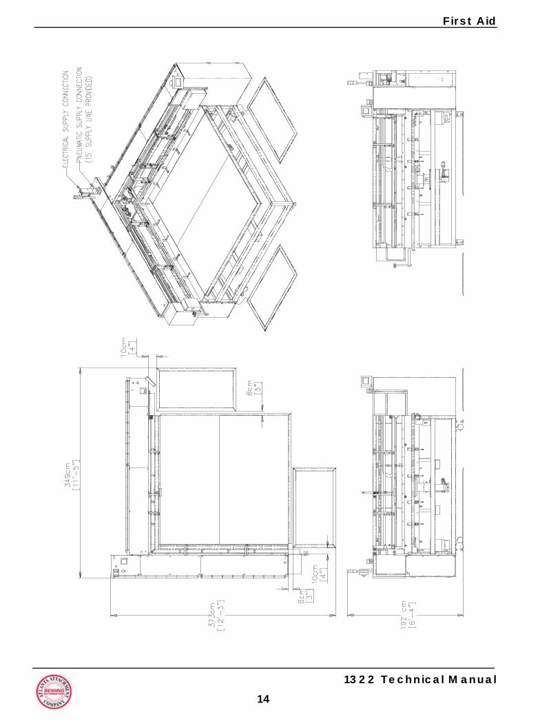
Safety Mat installationRefer to Figure 1 on the following page for correct installation locations. Mats must be secured to the floor as per maufacturers’ specifications. Refer to installation instructions (http://www.larcomfg.com/images/Downloads/IS7.pdf) to insure proper operation and operators safety.
12
First AidAmbiente de TrabajoNuestras máquinas están diseñadas para uso en cuartos cerrados:
• La Temperatura ambiental permisible de aproximadamente 5 - 40 °C (40 - 104 °F). Fallas de los sistemas de control y funciones inesperados en la máquina pueden ocurrir en temperaturas fuera de este rango.• Proteja la máquina contra los efectos climáticos como descargas electroestáticas, rayos, granizo, efectos de tormentas, exceso de humedad y aire salado en lugares cerca al mar.• Proteja la máquina contra los efectos del lugar de trabajo como vibraciones, polvo de esmeril, o vapores químicos.• Proteja la máquina contra acceso inautorizado. • Asegúrese que la máquina y los accesorios han sido montados de una manera estable.• Asegúrese fácil acceso de operación y mantenimiento (Manual de Instrucción y montaje). También verifique que el piso tenga suficiente resistencia para soportar el peso de la máquina.
Instalación de la Máquina Este equipo deber ser instalado por un técnico del Atlanta Attachment Co o un técnico / mecánico debidamente entrenado y autorizado. Atlanta Attachment Co. se reserva el derecho de anular la garantía de una máquina si la misma ha sido instalada por alguien no autorizado por la empresa.
Instalación de la Estera de SeguridadVer Figura 1 en la siguiente página para los lugares correctos de instalación. Las esteras deben estar aseguradas al piso según las especificaciones del fabricante. Vea las instrucciones de instalación en (http://www.larcomfg.com/images/Downloads/IS7.pdf) para asegurarse de la operación correcta y de la seguridad del operador.
1322 Technical Manual
First Aid
1322 Technical Manual
13
Regulaciones LocalesEn particular preste atención a las regulaciones locales, estatales, etc. cuando está instalando las máquinas y la planta (Por ejemplo, las rutas de escape). Anote las zonal de seguridad cerca de la máquina.
Conexión, ReconexiónLíneas de carga y descarga de energía deben ser instaladas en tal manera que no pasen por el área de trabajo del operador, no deben ser apretadas, aplastadas o dobladas y no deben ser estiradas ni tampoco pueden frotarse contra algo. Especialmente en el caso de líneas neumáticas, hidráulicas y eléctrica. Siempre tome en cuenta el movimiento de la máquina cuando está instalando las líneas.
Conexión EléctricaLa máquina solamente debe ser conectada a la red de energía eléctrica de la planta por un electricista calificado quien tenga conocimiento de los reglamentos locales. Antes de encender el interruptor principal verifique que todas las conexiones estén seguras.
Conección NeumáticaSe debe utilizar solamente aire comprimido seco y filtrado. Asegúrese que la presión del aire siempre se mantiene dentro de los rangos especificados. Caso contrario fallas pueden ocurrir.
Local RegulationsParticular attention must be paid to local and statutory regulations, etc. when installing machines and the plant (e.g. with regard to the specified escape routes). Note the safety zones in relation to adjacent machines.
Connection, ReconnectionEnergy feed and discharge lines must be routed so that they do not run through the operator's working area, are not compressed, crushed or buckled, are not subjected to tensile stresses and cannot rub against anything. This is particularly important in the case of pneumatic, hydraulic and electricity lines or hoses and always take the machine movements into account when routing such lines.
Electrical ConnectionThe machine shall only be connected to the factory power supply by a qualified electrician who is familiar with the local regulations. Before switching on the master switch, check that all fasteners are secure.
Pneumatic ConnectionOnly use dry filtered compressed air. Ensure that the air pressure always remains within the range specified, otherwise malfunctions may occur.
14
First Aid
1322 Technical Manual
Maintenance
MaintenanceGeneral Safety InstructionsThe machine shall be switched off, come to a standstill and be secured so that it cannot be switched on again inadvertently before starting any maintenance work whatsoever. Use proper lockout/tagout procedures to secure the machine against inadvertent startup.Remove any oil, grease, dirt and waste from the machine, particularly from the connections and screws, when starting the maintenance and/or repair work. Do not use any corrosive-cleaning agents. Use lint-free rags.Retighten all screw connections that have to be loosened for the maintenance and repair work. Any safety mechanisms that have to be dismantled for setting-up, maintenance or repair purposes must be refitted and checked immediately after completing the work.
Maintenance, Care, AdjustmentThe activities and intervals specified in the Instruction Manual for carrying out adjustments, maintenance and inspections must be observed and parts replaced as specified.
All hydraulic and pneumatic lines should be examined for leaks, loose connections, rubbing and damage whenever the machine is serviced. Any defects found must be remedied immediately.
Waste, Disassembly, DisposalWaste products should be cleared from the machine as soon as possible as not to create a fire hazard.
Ensure that fuels and operating lubricants, as well as replacement parts are disposed of in a safe and ecologically acceptable manner. Note the local regulations on pollution control.
When scrapping (disassembling) the machine and its assemblies, ensure that these materials are disposed of safely. Either commission a specialist company
1322 Technical Manual
15
MantenimientoInstrucciones Generales de SeguridadAntes de empezar cualquier trabajo de mantenimiento se debe apagar la máquina, esperar que todas las partes en movimiento se paren y asegurarlas contra la posibilidad del arranque inadvertido. Use los procedimientos adecuados con etiquetas de seguridad para prevenir un arranque inadvertido. Limpie toda la grasa, aceite, suciedad o basura de la máquina, en particular de las conexiones y tornillos antes de empezar con el trabajo de reparación o mantenimiento. No utilice limpiadores corrosivos. Utilice solamente trapos que no dejan pelusa. Reajuste todas las conexiones y tornillos que han sido aflojados durante el trabajo. Todas las piezas que han sido desarmadas para el mantenimiento o reparación tienen que ser armadas de nuevo e instaladas y revisadas tan pronto que se termine el trabajo.
Mantenimiento, Cuidado, AjusteLas actividades e intervalos especificados in el Manual de Instrucciones para los ajustes, mantenimiento e inspecciones tienen que ser observados y partes reemplazadas según indicado.Todas las líneas hidráulicas y neumáticas deben ser examinadas por fugas, conexiones sueltas y cualquier daño cuando se hace servicio a la máquina. Cualquier desperfecto debe ser corregido de inmediato.
Desechos, Desmontaje, DescarteLos desechos deben ser limpiados de la máquina lo mas pronto posible para eliminar el peligro de fuego.Asegurese que combustibles y lubricantes tal como piezas que han sido reemplazadas están descartadas en una manera segura y ecológicamente aceptable. Asegure que no infringe contra ninguna ley local contra contaminación ambiental. En el caso de desmantelar la máquina por completo asegúrese que todos los materiales sean descartados de una forma segura. Lo mejor seria contratar una empresa local
16
Repairque tenga conocimiento de las leyes locales o tenga en cuenta las leyes cuando está botando los materiales. Los materiales deben ser separados correctamente antes de descartarlos.
ReparaciónRepuestosNo podemos aceptar ninguna responsabilidad por daños resultados por uso de repuestos de otra marca o por reparación hecha por técnicos no calificados o de cualquier modificación realizada en la máquina.
Reparación EléctrícaLa fuente de energía eléctrica debe ser desconectada en el interruptor principal y el interruptor asegurado contra la posibilidad de arranque inadvertido de la máquina antes de empezar trabajos sobre el sistema Las medidas de protección implementadas (p.ej. resistencia a tierra) deben ser verificados antes de arrancar la máquina después de cualquier trabajo en el sistema eléctrico o sus componentes. Generadores de señales (interruptor de limite) y otras partes eléctricas en los mecanismos de seguridad no deben ser removidos o anulados. Use solamente fusibles o protecciones de circuitos con la capacidad de corriente especificada. La máquina debe ser apagada inmediatamente si ocurre una falla en la fuente de poder. El equipo eléctrico de nuestras máquinas debe ser revisado en intervalos regulares y cualquier desperfecto encontrado debe ser corregido de inmediato. Si es necesario trabajar en partes eléctricas con la energía conectada otra persona debe estar a la mano para activar el interruptor de emergencia o el interruptor principal en caso de emergencia. El área de trabajo debe ser restringida con un aviso de advertencia. Use solamente herramientas con protección aislante.
familiar with the local regulations or note the local regulations when disposing of these materials yourself. Materials should be sorted properly.
Repair Replacement Parts We cannot accept any liability whatsoever for damage due to the use of parts made by other manufacturers or due to unqualified repair or modification of the machine.
Repair, Electrical The power supply must be switched off (master switch off) and secured so that it cannot be switched on again inadvertently before starting any work on live parts.
The protective measures implemented (e.g. grounding resistance) must be tested before restarting the machine after all assembly or repair work on electric parts.
Signal generators (limit switches) and other electrical parts on the safety mechanisms must not be removed or bypassed. Only use original fuses or circuit overloads with the specified current rating. The machine must be switched off immediately if a fault develops in the electrical power supply.
The electrical equipment of our machines must be checked at regular intervals and any defects found must be remedied immediately. If it is necessary to carry out work on live parts, a second person should be on hand to operate the emergency OFF switch or master switch with voltage release in the event of an emergency. The working area should be cordoned off and marked by a warning sign. Only use electrically insulated tools.
1322 Technical Manual
Repair
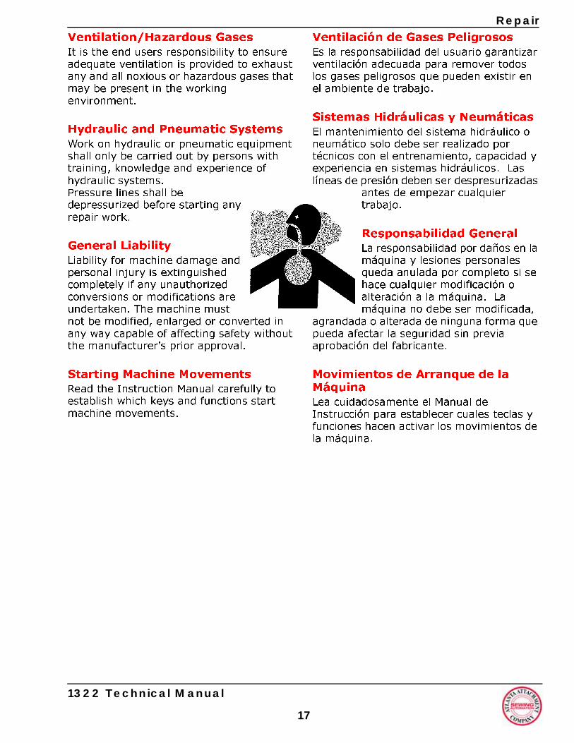
Ventilation/Hazardous GasesIt is the end users responsibility to ensure adequate ventilation is provided to exhaust any and all noxious or hazardous gases that may be present in the working environment.
Hydraulic and Pneumatic SystemsWork on hydraulic or pneumatic equipment shall only be carried out by persons with training, knowledge and experience of hydraulic systems.Pressure lines shall be depressurized before starting any repair work.
General LiabilityLiability for machine damage and personal injury is extinguished completely if any unauthorized conversions or modifications are undertaken. The machine must not be modified, enlarged or converted in any way capable of affecting safety without the manufacturer's prior approval.
Starting Machine MovementsRead the Instruction Manual carefully to establish which keys and functions start machine movements.
1322 Technical Manual
17
Ventilación de Gases PeligrososEs la responsabilidad del usuario garantizar ventilación adecuada para remover todos los gases peligrosos que pueden existir en el ambiente de trabajo.
Sistemas Hidráulicas y NeumáticasEl mantenimiento del sistema hidráulico o neumático solo debe ser realizado por técnicos con el entrenamiento, capacidad y experiencia en sistemas hidráulicos. Las líneas de presión deben ser despresurizadas
antes de empezar cualquier trabajo.
Responsabilidad GeneralLa responsabilidad por daños en la máquina y lesiones personales queda anulada por completo si se hace cualquier modificación o alteración a la máquina. La máquina no debe ser modificada,
agrandada o alterada de ninguna forma que pueda afectar la seguridad sin previa aprobación del fabricante.
Movimientos de Arranque de la MáquinaLea cuidadosamente el Manual de Instrucción para establecer cuales teclas y funciones hacen activar los movimientos de la máquina.
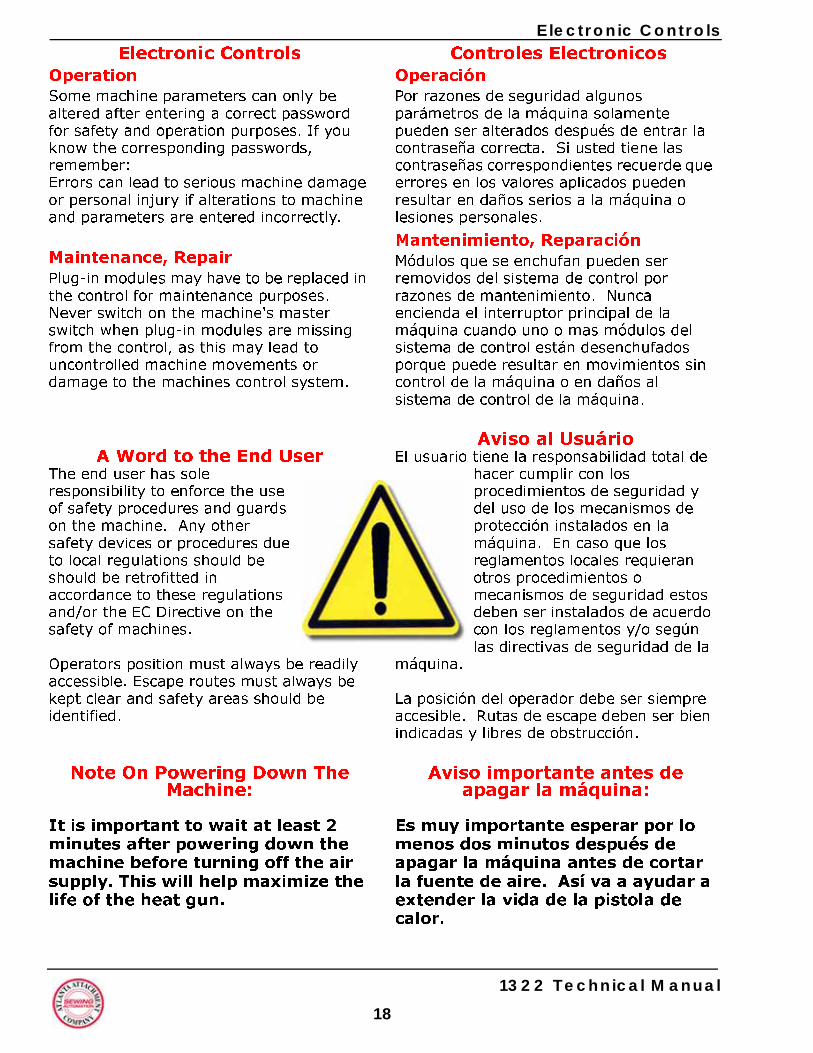
18
Electronic Controls Controles Electronicos
OperaciónPor razones de seguridad algunos parámetros de la máquina solamente pueden ser alterados después de entrar la contraseña correcta. Si usted tiene las contraseñas correspondientes recuerde que errores en los valores aplicados pueden resultar en daños serios a la máquina o lesiones personales.
Mantenimiento, ReparaciónMódulos que se enchufan pueden ser removidos del sistema de control por razones de mantenimiento. Nunca encienda el interruptor principal de la máquina cuando uno o mas módulos del sistema de control están desenchufados porque puede resultar en movimientos sin control de la máquina o en daños al sistema de control de la máquina.
Aviso al UsuárioEl usuario tiene la responsabilidad total de
hacer cumplir con los procedimientos de seguridad y del uso de los mecanismos de protección instalados en la máquina. En caso que los reglamentos locales requieran otros procedimientos o mecanismos de seguridad estos deben ser instalados de acuerdo con los reglamentos y/o según las directivas de seguridad de la
máquina.
La posición del operador debe ser siempre accesible. Rutas de escape deben ser bien indicadas y libres de obstrucción.
Aviso importante antes deapagar la máquina:
Es muy importante esperar por lo menos dos minutos después de apagar la máquina antes de cortar la fuente de aire. Así va a ayudar a extender la vida de la pistola de calor.
Electronic ControlsOperationSome machine parameters can only be altered after entering a correct password for safety and operation purposes. If you know the corresponding passwords, remember: Errors can lead to serious machine damage or personal injury if alterations to machine and parameters are entered incorrectly.
Maintenance, RepairPlug-in modules may have to be replaced in the control for maintenance purposes. Never switch on the machine's master switch when plug-in modules are missing from the control, as this may lead to uncontrolled machine movements or damage to the machines control system.
A Word to the End UserThe end user has sole responsibility to enforce the use of safety procedures and guards on the machine. Any other safety devices or procedures due to local regulations should be should be retrofitted in accordance to these regulations and/or the EC Directive on the safety of machines.
Operators position must always be readily accessible. Escape routes must always be kept clear and safety areas should be identified.
Note On Powering Down The Machine:
It is important to wait at least 2 minutes after powering down the machine before turning off the air supply. This will help maximize the life of the heat gun.
1322 Technical Manual
1322 Unibody Welder
1322 Unibody WelderMachine DescriptionModel 11322 Unibody Welder Workstation is a custom machine, designed and built specifically for the Sealy Corporation. The main purpose of this machine is to automate the manufacturing process for producing new "Polyethylene Foam Encased" innerspring units. The new encased innerspring design consists of a foam base panel welded to side foam segments, which are pre-installed around four sides of the innerspring. The machine is designed to weld and simultaneously trim-to-size, two perpendicular sides of the the innerspring unit at a time. The machine is manually loaded (requiring two or more operators) and it automatically detects the presence of the innerspring unit when it is placed within certain proximity to the work area. When the unit presence is detected, the machine automatically grips it in multiple places, locates it, and locks it in place. The height of the unit is automatically detected, two welding/trimming heads, simultaneously weld and trim the foam base panel to the foam sides. When the two sides are welded, the unit is automatically released and is ready to be (manually) rotated 180 degrees. After the rotation, and when in position, the unit is re-gripped, and the same weld/trim process is repeated on the remaining two sides. The completed unit is released and manually removed. The production rate of the machine is primarily dependent on the skill and experience of the operators.
1322 Technical Manual
19
1322Máquina de Soldadura Integral Detalles de la Maquina de SoldarLa máquina de soldadura Modelo 11322 es una máquina diseñada y fabricada específicamente para la Corporación Sealy. El propósito principal de la máquina es automatizar el proceso de manufactura de los nuevos colchones de resorte encajonado en espuma de polietileno (Polyethylene Foam Encased). El nuevo diseño de colchones de resorte encajonado consiste de un panel de espuma soldado a los segmentos de espuma laterales los cuales son preinstalados alrededor de los cuatro lados del resorte. La máquina está diseñada para soldar y al mismo tiempo cortar al tamaño dos lados adyacentes del colchón. La máquina se carga manualmente (se requieren dos o más operadores) y automáticamente detecta dos lados perpendiculares del colchón cuando se posiciona a cierta proximidad del área de trabajo. Cuando la unidad es detectada la máquina automáticamente apresa el colchón en varios lugares, lo posiciona y mantiene firme en posición. La altura de la unidad de resortes se detecta automáticamente, dos cabezales de soldar / recortar simultáneamente sueldan y recortan el panel de espuma a los laterales de espuma. Cuando termina de soldar los dos primeros lados la máquina suelta automáticamente el colchón y está listo para ser girado manualmente 180 grados. Después de la rotación y cuando el colchón está en posición el proceso de soldar y cortar se repite en los dos últimos lados. La unidad terminada es soltada y removida manualmente. La velocidad de producción de la máquina se depende principalmente en la experiencia y capacidad de los operadores.
2
General Machine DataDatos Generales de la Máquina
Instalación Electrica/Neumática Eléctrico: 230 VAC, Monofásico, 50/60 Hz, 16 amp, 3700 watios Neumático: 60-80 PSI, Promedio de 12 SCFM (Pies cúbicos por minuto)
Características de la Máquina• Pantalla de control táctil - Fácil actualización de futuros programas y funciones del operador.• Sistema de control modular - Repuestos comunes, cambio y pruebas rápidas.• Pistolas de calor de cambio rápido - Mínimo tiempo perdido en mantenimiento de la máquina• Sensor de control de temperatura de la pistola de calor - para prevenir daños al elemento de calor.• Cortador mecánico de borde - No Gases tóxicos• Cortador de alta velocidad, de acero, con auto afilado para larga vida.- Para mantener al mínimo el tiempo de uso perdido• Motor del cortador con protección térmica interna y sin carbones para una larga vida y sin necesidad de mantenimiento• Mesa con ajuste automático de altura - Para fácil ajuste entre colchones de distintas medidas• Contacto positivo entre colchón y bordes durante el proceso de soldadura - para producir un producto de alta calidad• Riel de alineación para el panel - Alineamiento más fácil de paneles• Rieles de seguridad - para prevenir lesiones personales accidentales• Sensores ópticos de seguridad durante recorte y sellado -para evitar lesiones accidentales• Tubo de desperdicios por gravedad - fácil de remover• Ciclo de operación "manos libres" - la máquina automáticamente termina ciclo de dos lados • Superficie de la mesa de Acero Inoxidable - limpia y sin oxido • Carriles de cables - para protección y extensión de la vida de los cables• Sistema de guías de acero endurecido con rodamientos de bolas para darles una larga vida y libre de mantenimiento• Correa reforzada con acero• Riel guía para el motor Servo para larga vida sin mantenimiento
General Machine DataElectrical / Pneumatic SetupElectrical: 230 VAC, Single Phase, 50/60 Hz, 16 amp, 3700 wattsPneumatic: 60-80 PSI, 12 SCFM avg.
Machine Features• Touch screen control - easy addition of future features and operator functions• Modular control system - common spare parts, quick replacement and testing• Quick change heat guns - to keep the machine downtime to a minimum• Heat gun temperature monitoring sensor - to prevent damage to heating element• Mechanical edge trimmer - no toxic smoke issues• High speed, steel, auto sharpening blade for long life - to keep the machine downtime to a minimum• Cutting blade motor internally thermo protected and brushless for a long, maintenence- free life• Auto table height adjustment - for easy adjustment between different mattress sizes• Positive contact between bed and fence during sealing - to produce quality product• Alignment fence for base panel - easier panel alignment• Safety guarding - to prevent incidental personal injury• Safety photo cells during trimming and sealing cycle - to prevent incidental injury• Waste removal chute, gravity method - easy to remove• Hands free machine cycle - machine automatically completes 2 side cycle• Stainless Steel table top - rust free and clean• Cable track carriers - for cable protection and long life• Hardened robust steel guide system with preloaded ball bearing block for long, trouble- free service life• Steel, reinforced drive belt• Servo motor guide rail drive for long, maintenence-free life
1322 Technical Manual
0
General Machine Data
Machine Cycle Time1. Manually load bed onto the table andpush into fence corner: 7 sec.2. Alignment pins automatically position
and hold the bed against the fence: 3 sec.
3. Position base panel: 7 sec.4. Auto height detection: 1 sec.5. Lower top edge clamps: 1 sec.6. Weld / Trim cycle: 12 sec.7. Lift top clamps: 1 sec.8. Manually rotate bed 180 degrees and
roughly push into the fence corner: 5 sec.
Pivot Weld/Trim heads and return home9. Alignment pins to position and hold the
bed against the fence: 3 sec.10. Lower top edge clamps: 1 sec.11. Weld / Trim cycle: 12 sec.12. Lift top clamps: 1 sec.13. Unload the bed, return Weld/Trim heads
home: 5 sec.
Total estimated cycle time: 59 sec.
Machine Setup and OperationModel 1322 Unibody Welder Workstation must be setup and adjusted according to the following instructions:
1. The installer will setup the machine according to Sealy’s requirements. After the machine installation, the installer will train the mechanics on machine setup and adjustments. The installer will also train the operators on the basic operation of the machine. The following manual provides essential reference information on the setup, operation, adjustments, and maintenance of the 1322 Unibody Welder Workstation. A 1322 Unibody Welder Workstation must be setup according to the instructions outlined in this section.
1322 Technical Manual
2
Tiempo de Ciclo de la Máquina1. Monte el colchón sobre la mesa y
presiónelo contra la esquina - 7 seg.2. Clavijas de alineamiento posicionan
autmáticamente y mantienen el colchón contra el borde: 3 seg.
3. Posicione el panel base: 7 seg.4. Detección automática de altura: 1 seg.5. Las prensas del borde superior bajan: 1
seg.6. Ciclo de soldar / recortar - 12 seg.7. Suben las prensas del borde superior -
1 seg.8. Rotación manual del colchón 180 grados
y colocación aproximada a la esquina - 5 seg.
9. Cabezales giran y vuelven a su posición - 1 seg.
10. Clavijas de alineación empujan y aseguran el colchón contra el riel: - 3 seg.
11. Las prensas del borde superior bajan - 1 seg.
12. Ciclo de soldar / recortar - 12 seg.13. Suben las prensas del borde superior -
1 seg.14. Descargar el colchón, retornar las
cabezas de soldar / cortar a su posición - 5 seg.
Tiempo total estimado del ciclo: 59 seg.
Instalación y Operación de la MáquinaEl Soldador Integral Modelo 1322 tiene que ser instalado y ajustado según las siguientes instrucciones:1. El instalador va instalar la máquina según los requerimientos de Sealy. Después de la instalación de la máquina el instalador entrenará a los mecánicos en la máquina y sus ajustes y su calibración. El instalador también dará instrucción a los operadores sobre la operación básica de la máquina. El siguiente manual provee información esencial sobre el ajuste, operación y mantenimiento del soldador Integral Modelo 1322. El Modelo 1322 tiene que ser armado siguiendo las instrucciones en la sección siguiente.
1
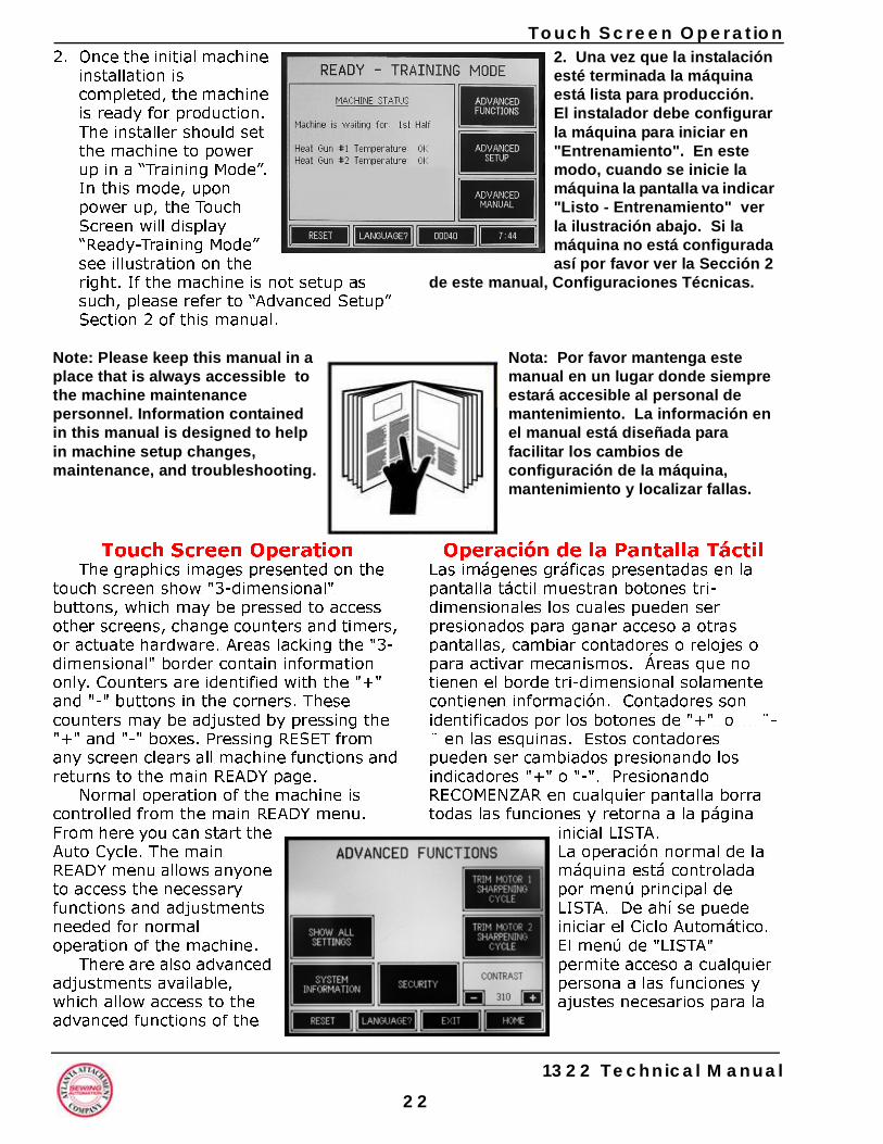
2
Touch Screen Operation2. Una vez que la instalación esté terminada la máquina está lista para producción. El instalador debe configurar la máquina para iniciar en "Entrenamiento". En este modo, cuando se inicie la máquina la pantalla va indicar "Listo - Entrenamiento" ver la ilustración abajo. Si la máquina no está configurada así por favor ver la Sección 2
de este manual, Configuraciones Técnicas.
Nota: Por favor mantenga este manual en un lugar donde siempre estará accesible al personal de mantenimiento. La información en el manual está diseñada para facilitar los cambios de configuración de la máquina, mantenimiento y localizar fallas.
Operación de la Pantalla TáctilLas imágenes gráficas presentadas en la pantalla táctil muestran botones tri-dimensionales los cuales pueden ser presionados para ganar acceso a otras pantallas, cambiar contadores o relojes o para activar mecanismos. Áreas que no tienen el borde tri-dimensional solamente contienen información. Contadores son identificados por los botones de "+" o ¨-¨ en las esquinas. Estos contadores pueden ser cambiados presionando los indicadores "+" o "-". Presionando RECOMENZAR en cualquier pantalla borra todas las funciones y retorna a la página
inicial LISTA.La operación normal de la máquina está controlada por menú principal de LISTA. De ahí se puede iniciar el Ciclo Automático. El menú de "LISTA" permite acceso a cualquier persona a las funciones y ajustes necesarios para la
2. Once the initial machine installation is completed, the machine is ready for production. The installer should set the machine to power up in a “Training Mode”. In this mode, upon power up, the Touch Screen will display “Ready-Training Mode” see illustration on the right. If the machine is not setup as such, please refer to “Advanced Setup” Section 2 of this manual.
Note: Please keep this manual in a place that is always accessible to the machine maintenance personnel. Information contained in this manual is designed to help in machine setup changes, maintenance, and troubleshooting.
Touch Screen OperationThe graphics images presented on the
touch screen show "3-dimensional" buttons, which may be pressed to access other screens, change counters and timers, or actuate hardware. Areas lacking the "3- dimensional" border contain information only. Counters are identified with the "+" and "-" buttons in the corners. These counters may be adjusted by pressing the "+" and "-" boxes. Pressing RESET from any screen clears all machine functions and returns to the main READY page.
Normal operation of the machine is controlled from the main READY menu. From here you can start the Auto Cycle. The main READY menu allows anyone to access the necessary functions and adjustments needed for normal operation of the machine.
There are also advanced adjustments available, which allow access to the advanced functions of the
1322 Technical Manual
2
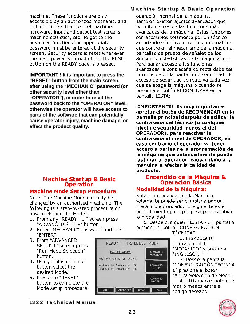
Machine Startup & Basic Operation
machine. These functions are only accessible by an authorized mechanic, and include: timers that control machine hardware, input and output test screens, machine statistics, etc. To get to the advanced functions the appropriate password must be entered at the security screen. Security access is reset whenever the main power is turned off, or the RESET button on the READY page is pressed.IMPORTANT ! It is important to press the “RESET” button from the main screen, after using the “MECHANIC” password (or other security level other than “OPERATOR”), in order to reset the password back to the “OPERATOR” level, otherwise the operator will have access to parts of the software that can potentially cause operator injury, machine damage, or effect the product quality.
Machine Startup & BasicOperation
Machine Mode Setup Procedure:Note: The Machine Mode can only be changed by an authorized mechanic. The following is a step-by-step procedure on how to change the Mode:1. From any “READY -… ” screen press
“ADVANCED SETUP” button2. Enter “MECHANIC” password and press
“ENTER”,3. From “ADVANCED
SETUP 1” screen press “Run Mode Selection” button.
4. Using a plus or minus button select the desired Mode.
5. Press the “RESET” button to complete the Mode setup procedure
1322 Technical Manual
2
operación normal de la máquina.También existen ajustes avanzados que permiten acceso a las funciones más avanzadas de la máquina. Estas funciones son accesibles solamente por un técnico autorizado e incluyen: relojes automáticos que controlan el mecanismo de la máquina, pantallas de prueba de señales de los Sensores, estadísticas de la máquina, etc. Para ganar acceso a las funciones avanzadas la contraseña correcta debe ser introducida en la pantalla de seguridad. El acceso de seguridad se reactiva cada vez que se apaga la máquina o cuando se presiona el botón RECOMENZAR en la pantalla LISTA:
¡IMPORTANTE! Es muy importante apretar el botón de RECOMENZAR en la pantalla principal después de utilizar la contraseña del técnico (o cualquier nivel de seguridad menos el del OPERADOR), para reactivar la contraseña al nivel de OPERADOR, en caso contrario el operador va tener acceso a partes de la programación de la máquina que potencialmente puede lastimar al operador, causar daño a la máquina o afectar la calidad del producto.
Encendido de la Máquina &Operación Básica
Modalidad de la Máquina:Nota: La modalidad de la Máquina solamente puede ser cambiada por un mecánico autorizado. El siguiente es el procedimiento paso por paso para cambiar la modalidad:
1. Desde cualquier ¨LISTA - …¨ pantalla presione el boton ¨CONFIGURACIÓN
TÉCNICA¨2. Introduce la
contraseña del "MECANICO" y presione "INGRESO",
3. Desde la pantalla "CONFIGURACIÓN TÉCINCA 1" presione el boton "Aplica Selección de Modo".
4. Utilizando el boton de mas o menos entre el código deseado.
3
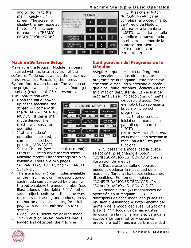
2
achine Startup & Basic Operation5. Presione el boton
"RECOMENZAR" parar completar el procedimiento de Arreglo de Modo y retorna para la pantalla ¨LISTO - … ¨. La pantalla va indicar el nuevo modo en el parte superior de la pantalla, por ejemplo: LISTO - MODO DE PRODUCIÓN¨.
Configuración del Programa de la MáquinaAsegúrese que el Módulo de Programa ha sido instalado con las última revisiones del programa de la máquina. Para hacer eso encienda la Máquina y presione el botón que dice Configuraciones Técnicas y luego Información del Sistema. La versión del programa va ser indicado como un número
de cuatro dígitos. (Por ejemplo 0105 representa la versión 1.05 del programa.
1. En el encendido inicial de la máquina la pantalla que aparece es "LISTO - ENTRENAMIENTO". Si esta es la modalidad deseada la máquina está lista para funcionar.
2. Si desea otra modalidad la puede seleccionar presionando el botón "CONFIGURACIÓNES TÉCNICAS" (vea la ilustración del medio)
3. Desde esta pantalla el operador puede seleccionar la modalidad de la máquina. También hay otras selecciones disponibles. Existen dos paginas "CONFIGURACIÓNES TÉCNICAS 1" y "CONFIGURACIÓNES TÉCNICAS 2".
4.Existen cuatro (4) modalidades de operación en la máquina 0 - 3. La descripción de cada modalidad puede ser revisada presionando el botón encima del número de la modalidad (vea ilustración a la Izq.). *** Todos los demás ajustes funcionan en la misma manera, para ganar acceso a los parámetros y opciones presione el botón encima de la modalidad
Mand to return to the main “Ready - …” screen. The screen will display the new mode at the top of the screen, for example: “READY – PRODUCTION MODE”.
Machine Software SetupMake sure the Program Module has been installed with the latest revision of the software. To do so, power up the machine, press Advanced Functions, then press System Information button. The version of the program will be displayed as a four digit number; (example 0105 represents ver. 1.05 system software.1. Upon the initial power
up of the machine the screen will come with the “READY – TRAINING MODE”. If this is the mode desired, the machine is ready for operation.
2. If other mode of operation is desired, it can be selected by pressing “ADVANCED SETUP” button (see middle illustration).
3. From this screen operator can select Machine modes. Other settings are also available. There are two pages “ADVANCED SETUP 1”, and “ADVANCED SETUP 2”,
4. There are four (4) Run modes available on the machine, 0-3. The description of each mode can be viewed by pressing the button above the mode number (see illustrations on the right). *** All other setup adjustments work the same way, to access the setting and options, press the button above the setting for a full page with detailed information for the setting.
5. Using – or +, select the desired mode. 6. In “Production Mode”, once the bed is
loaded and detected, the machine
1322 Technical Manual
4
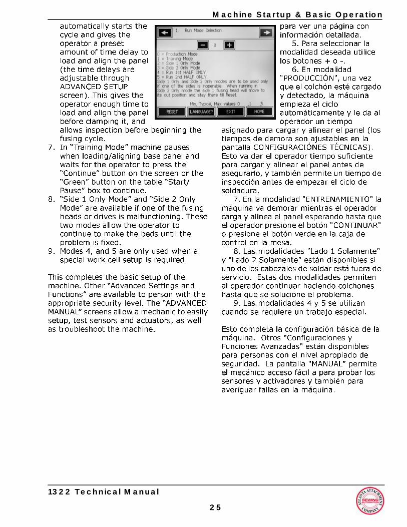
Machine Startup & Basic Operation
automatically starts the cycle and gives the operator a preset amount of time delay to load and align the panel (the time delays are adjustable through ADVANCED SETUP screen). This gives the operator enough time to load and align the panel before clamping it, and allows inspection before beginning the fusing cycle.7. In “Training Mode” machine pauses when loading/aligning base panel and waits for the operator to press the “Continue” button on the screen or the “Green” button on the table “Start/Pause” box to continue.
8. “Side 1 Only Mode” and “Side 2 Only Mode” are available if one of the fusing heads or drives is malfunctioning. These two modes allow the operator to continue to make the beds until the problem is fixed.
9. Modes 4, and 5 are only used when a special work cell setup is required.
This completes the basic setup of the machine. Other “Advanced Settings and Functions” are available to person with the appropriate security level. The “ADVANCED MANUAL” screens allow a mechanic to easily setup, test sensors and actuators, as well as troubleshoot the machine.
1322 Technical Manual
2
para ver una página con información detallada.
5. Para seleccionar la modalidad deseada utilice los botones + o -.
6. En modalidad "PRODUCCIÓN", una vez que el colchón esté cargado y detectado, la máquina empieza el ciclo automáticamente y le da al operador un tiempo
asignado para cargar y alinear el panel (los tiempos de demora son ajustables en la pantalla CONFIGURACIÓNES TÉCNICAS). Esto va dar el operador tiempo suficiente para cargar y alinear el panel antes de asegurarlo, y también permite un tiempo de inspección antes de empezar el ciclo de soldadura.
7. En la modalidad "ENTRENAMIENTO" la máquina va demorar mientras el operador carga y alinea el panel esperando hasta que el operador presione el botón "CONTINUAR" o presione el botón verde en la caja de control en la mesa.
8. Las modalidades "Lado 1 Solamente" y "Lado 2 Solamente" están disponibles si uno de los cabezales de soldar está fuera de servicio. Estas dos modalidades permiten al operador continuar haciendo colchones hasta que se solucione el problema.
9. Las modalidades 4 y 5 se utilizan cuando se requiere un trabajo especial.
Esto completa la configuración básica de la máquina. Otros "Configuraciones y Funciones Avanzadas" están disponibles para personas con el nivel apropiado de seguridad. La pantalla "MANUAL" permite el mecánico acceso fácil a para probar los sensores y activadores y también para averiguar fallas en la máquina.
5
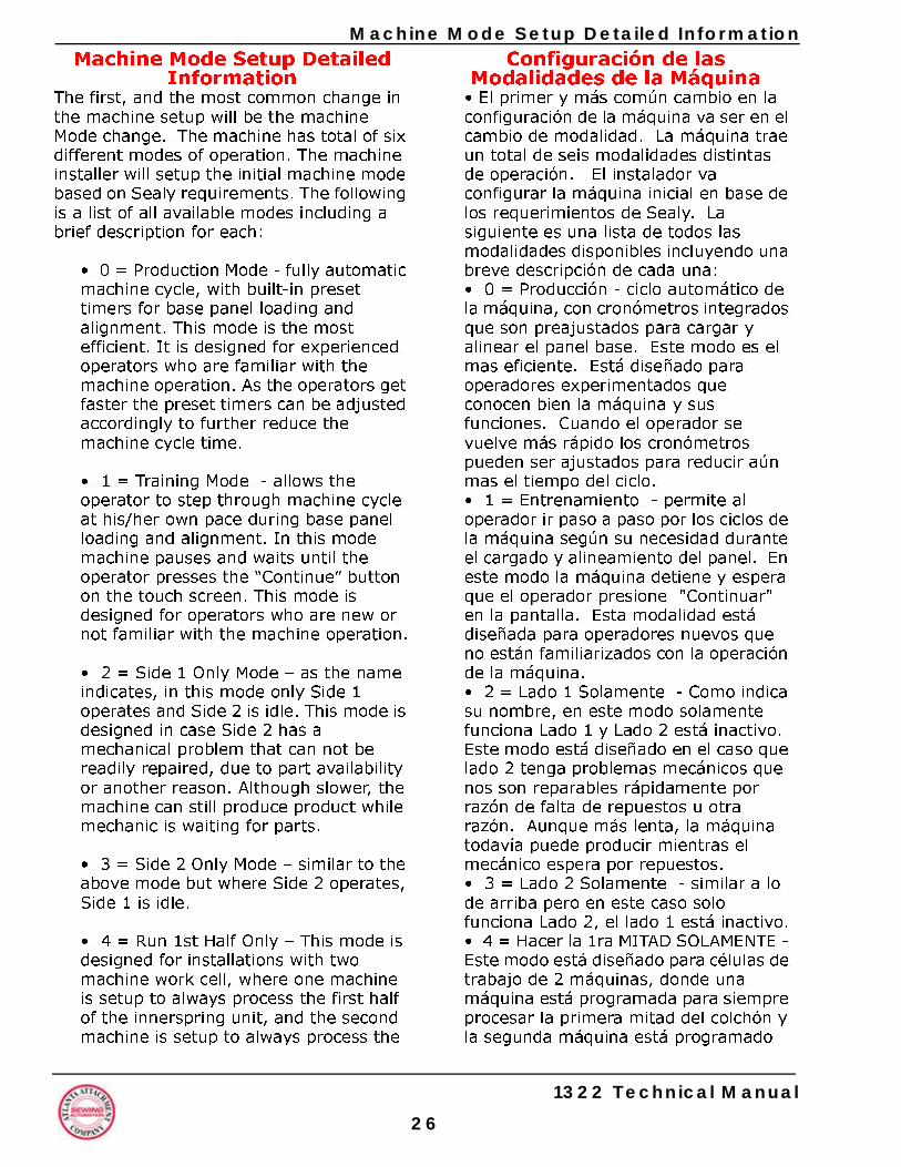
2
e Mode Setup Detailed InformationConfiguración de las
Modalidades de la Máquina• El primer y más común cambio en la configuración de la máquina va ser en el cambio de modalidad. La máquina trae un total de seis modalidades distintas de operación. El instalador va configurar la máquina inicial en base de los requerimientos de Sealy. La siguiente es una lista de todos las modalidades disponibles incluyendo una breve descripción de cada una: • 0 = Producción - ciclo automático de la máquina, con cronómetros integrados que son preajustados para cargar y alinear el panel base. Este modo es el mas eficiente. Está diseñado para operadores experimentados que conocen bien la máquina y sus funciones. Cuando el operador se vuelve más rápido los cronómetros pueden ser ajustados para reducir aún mas el tiempo del ciclo. • 1 = Entrenamiento - permite al operador ir paso a paso por los ciclos de la máquina según su necesidad durante el cargado y alineamiento del panel. En este modo la máquina detiene y espera que el operador presione "Continuar" en la pantalla. Esta modalidad está diseñada para operadores nuevos que no están familiarizados con la operación de la máquina. • 2 = Lado 1 Solamente - Como indica su nombre, en este modo solamente funciona Lado 1 y Lado 2 está inactivo. Este modo está diseñado en el caso que lado 2 tenga problemas mecánicos que nos son reparables rápidamente por razón de falta de repuestos u otra razón. Aunque más lenta, la máquina todavía puede producir mientras el mecánico espera por repuestos. • 3 = Lado 2 Solamente - similar a lo de arriba pero en este caso solo funciona Lado 2, el lado 1 está inactivo.• 4 = Hacer la 1ra MITAD SOLAMENTE - Este modo está diseñado para células de trabajo de 2 máquinas, donde una máquina está programada para siempre procesar la primera mitad del colchón y la segunda máquina está programado
MachinMachine Mode Setup Detailed
InformationThe first, and the most common change in the machine setup will be the machine Mode change. The machine has total of six different modes of operation. The machine installer will setup the initial machine mode based on Sealy requirements. The following is a list of all available modes including a brief description for each:
• 0 = Production Mode - fully automatic machine cycle, with built-in preset timers for base panel loading and alignment. This mode is the most efficient. It is designed for experienced operators who are familiar with the machine operation. As the operators get faster the preset timers can be adjusted accordingly to further reduce the machine cycle time.
• 1 = Training Mode - allows the operator to step through machine cycle at his/her own pace during base panel loading and alignment. In this mode machine pauses and waits until the operator presses the “Continue” button on the touch screen. This mode is designed for operators who are new or not familiar with the machine operation.
• 2 = Side 1 Only Mode – as the name indicates, in this mode only Side 1 operates and Side 2 is idle. This mode is designed in case Side 2 has a mechanical problem that can not be readily repaired, due to part availability or another reason. Although slower, the machine can still produce product while mechanic is waiting for parts.
• 3 = Side 2 Only Mode – similar to the above mode but where Side 2 operates, Side 1 is idle.
• 4 = Run 1st Half Only – This mode is designed for installations with two machine work cell, where one machine is setup to always process the first half of the innerspring unit, and the second machine is setup to always process the
1322 Technical Manual
6
Machine Mode Setup Detailed Information
second half. Machine setup in this mode will extend the panel alignment pin cylinders every machine cycle.• 5 = Run 2nd Half Only – This mode is designed for two machine work cell as outlined in Run 1st Half Only. The main difference between the Run 1st Half Only Mode, and the Run 2nd Half Only Mode, is that the panel alignment pin cylinders will never come up, in the 2nd Half Only Mode setup. This is to prevent any possibility of interference with a potentially excessive base panel trim on the second half.
1322 Technical Manual
2
para hacer solamente la segunda mitad. En ésta modalidad las guías de alineación se van a extender en cada ciclo.• 5 = Hacer la 2da MITAD SOLAMENTE - Este modalidad está diseñada para instalaciones con dos máquinas funcionando como fue indicado arriba. La diferencia más notable en estas dos modalidades es que las guías para alinear el panel nunca van a subir. Esto es para prevenir cualquier posibilidad de interferencia con un corte excesivo en el panel durante el segundo ciclo.
7
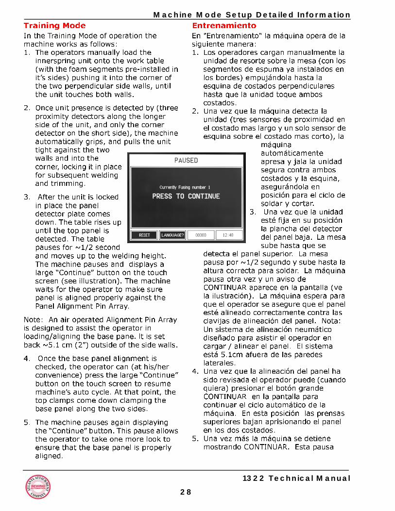
2
e Mode Setup Detailed InformationEntrenamientoEn "Entrenamiento" la máquina opera de la siguiente manera: 1. Los operadores cargan manualmente la
unidad de resorte sobre la mesa (con los segmentos de espuma ya instalados en los bordes) empujándola hasta la esquina de costados perpendiculares hasta que la unidad toque ambos costados.
2. Una vez que la máquina detecta la unidad (tres sensores de proximidad en el costado mas largo y un solo sensor de esquina sobre el costado mas corto), la
máquina automáticamente apresa y jala la unidad segura contra ambos costados y la esquina, asegurándola en posición para el ciclo de soldar y cortar.
3. Una vez que la unidad esté fija en su posición la plancha del detector del panel baja. La mesa sube hasta que se
detecta el panel superior. La mesa pausa por ~1/2 segundo y sube hasta la altura correcta para soldar. La máquina pausa otra vez y un aviso de CONTINUAR aparece en la pantalla (ve la ilustración). La máquina espera para que el operador se asegure que el panel esté alineado correctamente contra las clavijas de alineación del panel. Nota: Un sistema de alineación neumático diseñado para asistir el operador en cargar / alinear el panel. El sistema está 5.1cm afuera de las paredes laterales.
4. Una vez que la alineación del panel ha sido revisada el operador puede (cuando quiera) presionar el botón grande CONTINUAR en la pantalla para continuar el ciclo automático de la máquina. En esta posición las prensas superiores bajan aprisionando el panel en los dos costados.
5. Una vez más la máquina se detiene mostrando CONTINUAR. Esta pausa
MachinTraining ModeIn the Training Mode of operation the machine works as follows:1. The operators manually load the
innerspring unit onto the work table (with the foam segments pre-installed in it’s sides) pushing it into the corner of the two perpendicular side walls, until the unit touches both walls.
2. Once unit presence is detected by (three proximity detectors along the longer side of the unit, and only the corner detector on the short side), the machine automatically grips, and pulls the unit tight against the two walls and into the corner, locking it in place for subsequent welding and trimming.
3. After the unit is locked in place the panel detector plate comes down. The table rises up until the top panel is detected. The table pauses for ~1/2 second and moves up to the welding height. The machine pauses and displays a large “Continue” button on the touch screen (see illustration). The machine waits for the operator to make sure panel is aligned properly against the Panel Alignment Pin Array.
Note: An air operated Alignment Pin Array is designed to assist the operator in loading/aligning the base pane. lt is set back ~5.1 cm (2”) outside of the side walls.
4. Once the base panel alignment is checked, the operator can (at his/her convenience) press the large “Continue” button on the touch screen to resume machine’s auto cycle. At that point, the top clamps come down clamping the base panel along the two sides.
5. The machine pauses again displaying the “Continue” button. This pause allows the operator to take one more look to ensure that the base panel is properly aligned.
1322 Technical Manual
8
Machine Mode Setup Detailed Information
6. If the operator is satisfied with the alignment, he/she must step off the Safety Mat 2 and press the “Continue” button on the touch screen to resume automatic operation.
Note: A “Safety Mat 2 - Error” will be displayed on the screen if the operator forgets to step-off the Safety Mat 2 after pressing the“Continue” button. If that occurs, the operator can simply step off the mat and the machine will automatically resume its automatic operation.
7. The two trimming blades on both welding/trimming heads start to spin up, about two seconds after both carriages begin the welding and trimming cycle.
Note: The operator must step ON the Safety Mat during innerspring loading, and can step OFF the mat at any time after the innerspring is detected and pulled against walls. The operator must step off Safety Mat 2 before the welding heads begin their forward movement. This ensures that the safety mat is working properly.
Caution! If anyone steps back on Safety Mat 2 when head #2 is still within 3ft (or 1 meter) from it’s home, or steps on Safety Mat 1 when it approaches the last 3ft (or 1Meter) of its travel, the machine will stop, the heads will retract, and the corresponding Safety Mat Error will be displayed.
8. Once the welding/trimming cycle on first half of the innerspring is completed, both heads return home, the innerspring is released and ready for 180 degree rotation. Once the bed is rotated, the steps 1-6 are repeated.
9. After the second half of the innerspring is welded and trimmed the unit is again released. This step completes manufacturing of one innerspring unit.
1322 Technical Manual
2
permite que el operador se asegure que el panel está alineado correctamente.
6. Si el operador está satisfecho con la alineación él / ella tiene bajarse de la Estera de Seguridad 2 y presionar el botón CONTINUAR en la pantalla para continuar la operación automática.
Nota: Un mensaje ERROR ESTERA DE SEGURIDAD 2 - aparecerá en la pantalla si el operador se olvida de salir de la Estera de Seguridad 2 después de pulsar el botón CONTINUAR. Si esto ocurre el operador simplemente puede salir de la estera y la máquina continuará su operación automática.
7. Las dos cortadoras en ambos cabezales empiezan a girar aproximadamente dos segundos después que ambos cabezales empiezan el ciclo de soladura y recorte.
Nota: El operador tiene que estar sobre la Estera de Seguridad cuando está cargando la unidad de resortes, y puede salir de la estera en cualquier momento después que el resorte sea detectado y jalado contra las paredes. El operador tiene que bajarse de la Estera de Seguridad 2 antes que las cabezas comiencen a moverse hacia adelante. Esto reafirma que la estera está funcionando como debe. ¡Advertencia! Si alguien se sube sobre la Estera de Seguridad 2 cuando el cabezal 2 está a menos de un metro de su lugar de descanso, o si alguien pisa sobre la estera de Seguridad 1 cuando se aproxima a su último metro de movimiento la máquina va detenerse, las cabezas van a volver a su posición neutral, y el mensaje de error correspondiente aparecerá en la pantalla. 8. Una vez que el ciclo de soldar / recortar
en la primera mitad del colchón esté completo, ambas cabezas retornan a su posición neutral, el colchón es soltado y listo parar rotarlo 180 grados. Una vez girado se repiten los pasos 1-6.
9. Después que la segunda mitad del colchón haya sido soldado y recortado la unidad es soltada otra vez. Este paso completa la fabricación de una unidad de resortes.
9
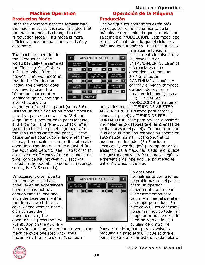
3
Machine OperationOperación de la Máquina
ProducciónUna vez que los operadores estén más cómodos con el funcionamiento de la máquina, se recomienda que la modalidad se cambie a PRODUCCIÓN. Esta modalidad es más eficiente debido que el ciclo de la máquina es automático. En PRODUCCIÓN
la máquina funciona básicamente lo mismo que los pasos 1-8 en ENTRENAMIENTO. La única diferencia es que el operador no tiene que apretar el botón CONTINUAR después de cargar / alinear y tampoco después de revisar la posición del panel (pasos 3-6). En vez, en PRODUCCIÓN la máquina
utiliza dos pausas TIEMPO DE AJUSTE Y ALINEAMIENTO (utilizado para cargar y alinear el panel), y TIEMPO DE PRE-CORTADO (utilizado para revisar la posición y alineamiento después que las prensas de arriba apresan el panel). Cuando terminan la cuenta la máquina reanuda su operación automática normal. Los cronómetros pueden ser ajustados (En Funciones Técnicas 1, ver dibujos) para optimizar la eficiencia de la máquina. Cada reloj puede ser ajustado entre 1 y 9 segundos según la experiencia del operador, el promedio es entre 3 y cinco segundos.
En ocasiones, normalmente por razones de problemas con el panel, hasta un operador experimentado no tiene suficiente tiempo para cargar y alinear el panel en el tiempo permitido. En este caso (si los cabezales no se han movido todavía) el operador puede oprimir el botón rojo de la caja auxiliar de control de
Pausa / reiniciar, para parar y volver la máquina un paso atrás, lo que soltará el panel (la caja auxiliar está ubicada debajo
Machine OperationProduction ModeOnce the operators become familiar with the machine cycle, it is recommended that the machine mode is changed to the “Production Mode”. This mode is more efficient, since the machine cycle is fully automatic.
The machine operation in the “Production Mode” works basically the same as the “Training Mode” steps 1-8. The only difference between the two modes is that in the “Production Mode”, the operator does not have to press the “Continue” button after loading/aligning, and again after checking the alignment of the base panel (steps 3-6). Instead, in the “Production Mode” machine uses two pause timers, called “Set and Align Time” (used for base panel loading and aligning), and “Pre-Cut Check Time” (used to check the panel alignment after the Top Clamps clamp the panel). These pause timers count down, and when they elapse, the machine resumes its automatic operation. The timers can be adjusted (in the Advanced Setup 1, see illustrations) to optimize the efficiency of the machine. Each timer can be set between 1-9 seconds based on the operator experience (average setting is ~3-5 seconds).
On occasion, often due to problems with the base panel, even an experienced operator may not have enough time to load and align the base panel within the time allowed. In that case, (if the welding heads did not start their movement yet) the operator can press the Red Pushbutton on the auxiliary Pause/Restart box, to stop and reverse the machine cycle one step back, thus unclamping the base panel (the box is
1322 Technical Manual
0
Machine Operation
located under the edge of the table, see illustration on the right). This machine feature allows the operator to reload or realign the base panel. To resume automatic operation, operator needs to press the Green Pushbutton (on the same auxiliary box). if the welding heads start their movement pressing Red Pushbutton will reset the machine, and send all mechanisms back to home positions.Machine Operation – Side 1 Only ModeThis mode is designed in case Side 2 has a serious mechanical or electrical problem, which can not be readily repaired. In this mode, the machine operates very similarly to the Production Mode, but with one major difference – while Side 1 is welding and cutting as normal, Side 2 is completely disabled. When operated in this mode, the unit must be rotated three times to complete one unit; therefore the machine is capable of producing only about 30% of its normal output. This mode was developed to facilitate production until repair of Side 2 can be made.
Machine Operation – Side 2 Only ModeThis mode is designed in case Side 1 has a serious mechanical or electrical problem, which can not be readily repaired. In this mode, machine operates very similarly to the Production Mode, but with one major difference - Side 2 is welding and cutting as normal, but Side 1 is completely disabled. When operated in this mode, the unit must be rotated three times to complete one unit; therefore the machine is capable of producing only about 30% of its normal output. This mode was developed to facilitate production until repair of Side 1 can be made.
Machine Operation – Run 1st Half Only ModeThis mode is designed for installations with a two machine work cell, where one machine is setup to always process the first
1322 Technical Manual
3
del borde de la mesa, ve dibujo al lado). Esta función de la máquina permite el operador recargar y realinear el panel. Parar reiniciar operación automática el operador solamente presione el botón verde (en la misma caja auxiliar). Si los cabezales ya han empezado su movimiento oprimir el botón rojo va recomenzar la máquina haciendo volver todos los mecanismos a su posición inicial.
Operación de la Máquina - Lado 1 SolamenteEl propósito de esta modalidad es que en caso que el lado 2 tenga un desperfecto mecánico o eléctrico que no pueda ser reparado fácilmente. En este modo la máquina opera muy similar a Producción con la diferencia que - mientras que el lado uno está soldando y cortando el lado dos está completamente desactivado. Cuando se opera en este modo el panel tiene que ser girado tres veces para completar una unidad, así que la máquina solo puede producir un 30% de lo normal. Este modo fue desarrollado para facilitar producción hasta que las reparaciones del lado 2 puedan ser realizadas.
Operación de la Máquina - Lado 2 SolamenteEsta modalidad está diseñada en caso que el lado 1 tenga un daño mecánico o eléctrico que no puede ser reparado fácilmente. En este modo la máquina opera muy similar al Modo de Producción con la diferencia principal que - mientras que el lado 2 esté soldando y cortando el lado 1 está completamente desactivado. Cuando se opera en este modo el panel tiene que ser girado tres veces para completar una unidad, así que la máquina está capaz de producir solamente un 30% de su producción normal. Esto modo fue desarrollado para facilitar producción hasta que las reparaciones de lado 1 puedan ser realizadas.
1
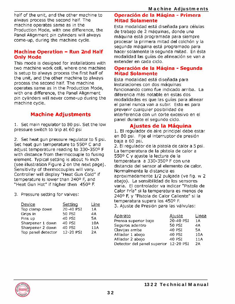
3
Machine AdjustmentsOperación de la Máqina - Primera Mitad SolamenteEsta modalidad está diseñada para células de trabajo de 2 máquinas, donde una máquina está programada para siempre procesar la primera mitad del colchón y la segunda máquina está programado para hacer solamente la segunda mitad. En ésta modalidad las guías de alineación se van a extender en cada ciclo.
Operación de la Máqina - Segunda Mitad SolamenteEsta modalidad está diseñada para instalaciones con dos máquinas funcionando como fue indicado arriba. La diferencia más notable en estas dos modalidades es que las guías para alinear el panel nunca van a subir. Esto es para prevenir cualquier posibilidad de interferencia con un corte excesivo en el panel durante el segundo ciclo.
Ajustes de la Máquina1. El regulador de aire principal debe estar en 80 psi. Fije el interruptor de presión baja a 60 psi.2. El regulador de la pistola de calor a 5 psi. La temperatura de la pistola de calor a 550º C y ajuste la lectura de la temperatura a 330-350º F con una distancia del sensor al elemento de calor. Normalmente la distancia es aproximadamente 1/2 pulgada (ve fig. w 2 abajo). La sensibilidad de los sensores varia. El controlador va indicar "Pistola de Calor Fría" si la temperatura es menos de 240º F, y "Pistola de Calor Caliente" si la temperatura supera los 450º F. 3. Ajuste de Presión para las válvulas:
Aparato Ajuste LineaPrensa superior bajo 20-40 PSI 1ASeguros adentro 50 PSI 4AClavijas arriba 40 PSI 5AAfilador 1 abajo 40 PSI 10AAfilador 2 abajo 40 PSI 11ADetector del panel superior 12-20 PSI 2A
half of the unit, and the other machine to always process the second half. The machine operates same as in the Production Mode, with one difference, the Panel Alignment pin cylinders will always come-up, during the machine cycle.
Machine Operation – Run 2nd Half Only ModeThis mode is designed for installations with two machine work cell, where one machine is setup to always process the first half of the unit, and the other machine to always process the second half. The machine operates same as in the Production Mode, with one difference, the Panel Alignment pin cylinders will never come-up during the machine cycle.
Machine Adjustments
1. Set main regulator to 80 psi. Set the low pressure switch to trip at 60 psi
2. Set heat gun pressure regulator to 5 psi. Set heat gun temperature to 550º C and adjust temperature reading to 330-350º F with distance from thermocouple to fusing element. Typical setting is about ½ inch (see illustration Figure 2 on the next page). Sensitivity of thermocouples will vary. Controller will display “Heat Gun Cold” if temperature is lower than 240º F, and “Heat Gun Hot” if higher then 450º F.
3. Pressure setting for valves:
Device Setting LineTop clamp down 20-40 PSI 1AGrips in 50 PSI 4APins up 40 PSI 5ASharpener 1 down 40 PSI 10ASharpener 2 down 40 PSI 11ATop panel detector 12-20 PSI 2A
1322 Technical Manual
2
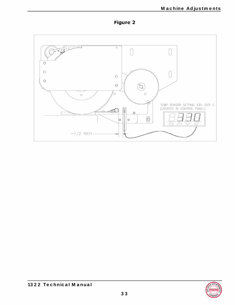
Machine Adjustments
Figu
1322 Technical Manual
3
re 2
3
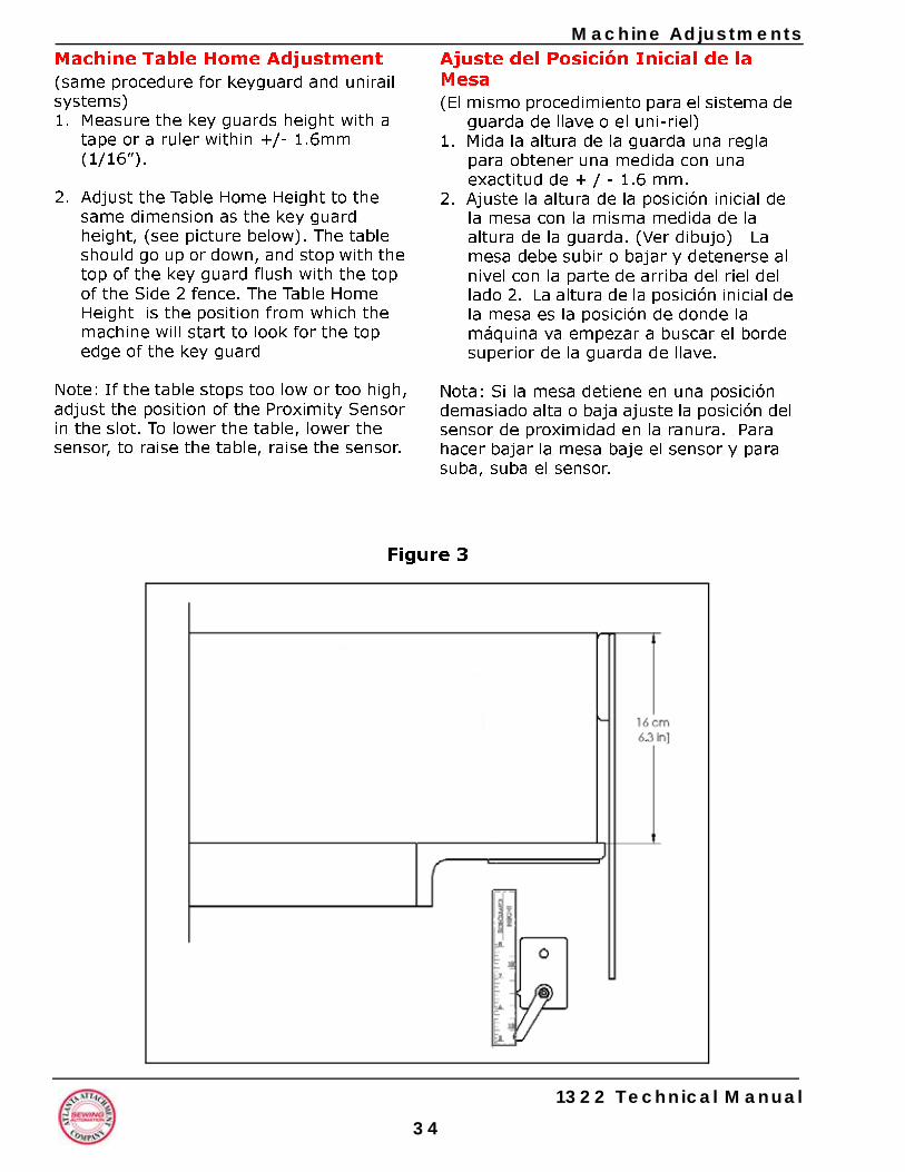
3
Machine AdjustmentsAjuste del Posición Inicial de la Mesa(El mismo procedimiento para el sistema de
guarda de llave o el uni-riel)1. Mida la altura de la guarda una regla
para obtener una medida con una exactitud de + / - 1.6 mm.
2. Ajuste la altura de la posición inicial de la mesa con la misma medida de la altura de la guarda. (Ver dibujo) La mesa debe subir o bajar y detenerse al nivel con la parte de arriba del riel del lado 2. La altura de la posición inicial de la mesa es la posición de donde la máquina va empezar a buscar el borde superior de la guarda de llave.
Nota: Si la mesa detiene en una posición demasiado alta o baja ajuste la posición del sensor de proximidad en la ranura. Para hacer bajar la mesa baje el sensor y para suba, suba el sensor.
re 3
Machine Table Home Adjustment(same procedure for keyguard and unirail systems)1. Measure the key guards height with a
tape or a ruler within +/- 1.6mm(1/16”).
2. Adjust the Table Home Height to the same dimension as the key guard height, (see picture below). The table should go up or down, and stop with the top of the key guard flush with the top of the Side 2 fence. The Table Home Height is the position from which the machine will start to look for the top edge of the key guard
Note: If the table stops too low or too high, adjust the position of the Proximity Sensor in the slot. To lower the table, lower the sensor, to raise the table, raise the sensor.
Figu
1322 Technical Manual
4
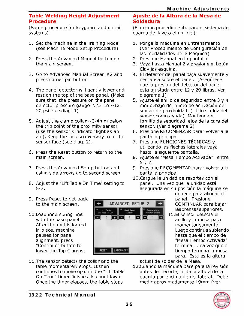
Machine Adjustments
Table Welding Height Adjustment Procedure(Same procedure for keyguard and unirail systems)1. Set the machine in the Training Mode (see Machine Mode Setup Procedure)
2. Press the Advanced Manual button on the main screen.
3. Go to Advanced Manual Screen #2 and press corner pin button
4. The panel detector will gently lower and rest on the top of the base panel. (Make sure that the pressure on the panel detector pressure gauge is set to ~12-20 psi. see diag. 1)
5. Adjust the clamp collar ~3-4mm below the trip point of the proximity sensor (use the sensor's indicator light as an aid). Keep the lock screw away from the sensor face (see diag. 2).
6. Press the Reset button to return to the main screen.
7. Press the Advanced Setup button and using side arrows go to second screen
8. Adjust the “Lift Table On Time" setting to 5-7.
9. Press Reset to get back to the main screen.
10.Load innerspring unit with the base panel. After the unit is locked in place, machine pauses for panel alignment. press “Continue” button to lower the Top Clamps.
11.The sensor detects the collar and the table momentarely stops. It then continues to move up until the "Lift Table On Time" timer finishes its countdown. Once the timer elapses, the table stops
1322 Technical Manual
3
Ajuste de la Altura de la Mesa de Soldadura(El mismo procedimiento para el sistema de guarda de llave o el uni-riel)
1. Ponga la máquina en Entrenamiento (Ver Procedimiento de Configuración de las modalidades de la Máquina)
2. Presione Manual en la pantalla3. Vaya hasta Manual 2 y presione el botón
Clavijas esquina. 4. El detector del panel baja suavemente y
descansa sobre el panel. (Asegúrese que la presión del detector del panel está ajustada entre 12 y 20 libras. Ver diagrama 1)
5. Ajuste el anillo de seguridad entre 3 y 4 mm debajo del punto de activación del sensor de proximidad. (Utilice la luz del sensor como ayuda) Mantenga el tornillo de seguridad lejos de la cara del sensor. (Ver diagrama 2)
6. Presione RECOMENZAR parar volver a la pantalla principal.
7. Presione FUNCIONES TÉCNICAS y utilizando las flechas laterales vaya hasta la siguiente pantalla.
8. Ajuste el "Mesa Tiempo Activada" entre 5 y 7.
9. Presione RECOMENZAR parar volver a la pantalla principal.
10.Cargue la unidad de resortes con el panel. Una vez que la unidad está asegurada en su posición la máquina se
detiene para alinear el panel. Presione CONTINUAR para bajar las prensas superiores.
11.El sensor detecta el anillo y la mesa para momentáneamente. Luego continua subiendo hasta que el tiempo de "Mesa Tiempo Activada" termina. Una vez que el tiempo termina la mesa para. Esta es la altura
actual de soldar de la Mesa.12.Cuando la máquina pare para la revisión
antes del recorte, mida la altura de la guarda por encima de riel lateral. Debe medir aproximadamente 10mm (ver
5
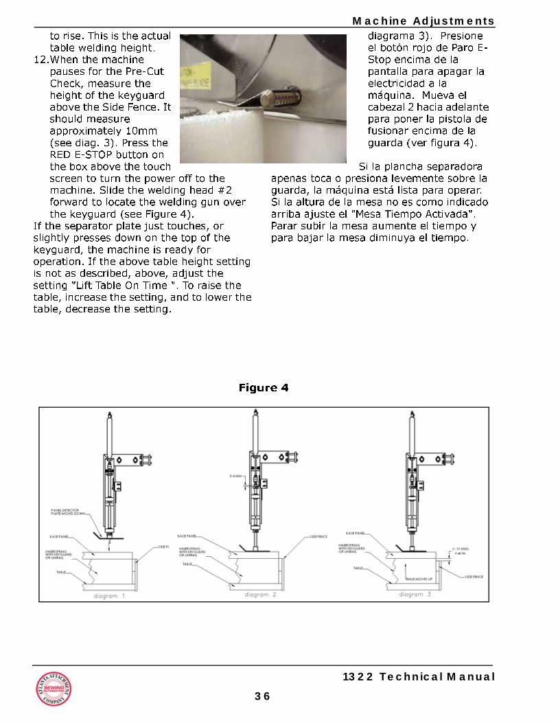
3
Machine Adjustmentsdiagrama 3). Presione el botón rojo de Paro E-Stop encima de la pantalla para apagar la electricidad a la máquina. Mueva el cabezal 2 hacia adelante para poner la pistola de fusionar encima de la guarda (ver figura 4).
Si la plancha separadora apenas toca o presiona levemente sobre la guarda, la máquina está lista para operar. Si la altura de la mesa no es como indicado arriba ajuste el "Mesa Tiempo Activada". Parar subir la mesa aumente el tiempo y para bajar la mesa diminuya el tiempo.
re 4
to rise. This is the actual table welding height.
12.When the machine pauses for the Pre-Cut Check, measure the height of the keyguard above the Side Fence. It should measure approximately 10mm (see diag. 3). Press the RED E-STOP button on the box above the touch screen to turn the power off to the machine. Slide the welding head #2 forward to locate the welding gun over the keyguard (see Figure 4).
If the separator plate just touches, or slightly presses down on the top of the keyguard, the machine is ready for operation. If the above table height setting is not as described, above, adjust the setting "Lift Table On Time ". To raise the table, increase the setting, and to lower the table, decrease the setting.
Figu
1322 Technical Manual
6
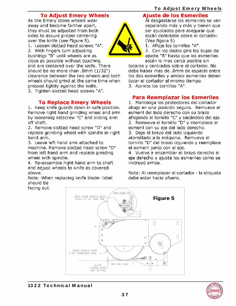
To Adjust Emery Wheels
To Adjust Emery WheelsAs the Emery stone wheels wear away and become farther apart, they must be adjusted from both sides to assure proper centering over the knife (see Figure 5).1. Loosen slotted head screws "A".2. With fingers turn adjusting bushings "B" until wheels are as close as possible without touching and are centered over the knife. There should be no more than .8mm (1/32”) clearance between the two wheels and both wheels should grind at the same time when pressed lightly against the knife.3. Tighten slotted head screws "A".
To Replace Emery Wheels1. Keep knife guards down in safe position. Remove right hand grinding wheel and arm by loosening setscrew "C" and sliding arm off shaft.2. Remove slotted head screw "D" and replace grinding wheel with spindle in right hand arm.3. Leave left hand arm attached to machine. Remove slotted head screw "D" from left hand arm and replace grinding wheel with spindle.4. Re-assemble right hand arm to shaft and adjust wheels to knife as covered above.Note: When replacing knife blade- label should be facing out.
1322 Technical Manual
3
Ajuste de los EsmerilesAl desgastarse los esmeriles se van separando más y más y tienen que ser ajustados para asegurar que están centrados sobre el cortador. (Vea figura 5) 1. Afloje los tornillos "A".2. Con los dedos gire los bujes de ajuste "B" hasta que los esmeriles estén lo mas cerca posible sin
tocarse y centrados sobre el cortador. No debe haber mas de .8mm de espacio entre los dos esmeriles y ambos esmeriles deben tocar el cortador al mismo tiempo.3. Apriete los tornillos "A".
Para Reemplazar los Esmeriles1. Mantenga los protectores del cortador abajo en una posición segura. Remueva el esmeril del lado derecho con su brazo aflojando el tornillo "C" y sacándolo del eje. 2. Remueva el tornillo "D" y reemplace el esmeril con su eje del lado derecho. 3. Deje el brazo del lado izquierdo atornillado a la máquina. Remueva el tornillo "D" del brazo izquierdo y reemplace el esmeril junto con el eje.4. Vuelve a ensamblar el brazo derecho al eje derecho y ajuste los esmeriles como se instruyó arriba.
Nota: Al reemplazar el cortador - la etiqueta debe estar hacia afuera.
Figure 5
7

1322 Technical Manual
To Replace Emery Wheels
38
NotasNotes
Programming ACTech SCL/SCM Drive
1322 Technical Manual
3
Programación de la Caja ACTech SCL/SCM
La caja ya viene con el programa instalado** con parámetros específicos para el Soldador 11322 de Atlanta Attachment Co. Los parámetros están listados en la gráfica en la siguiente página. La protección con contraseña está deshabilitada para fácil acceso a los parámetros. Después que los parámetros han sido comprobados y afinados se puede introducir una contraseña entre 1 y 999 en el parámetro 44 para proteger la configuración de los motores. (Vea página 22 de Manual de ACTech).
Los botones y números en la cara del controlador pueden ser utilizados para cambiar cualquier parámetro especifico. Presionando el botón "Modo" le lleva al último parámetro visto. Los Parámetros son designados con una "P" como primer letra en la ventanilla. Las flechas arriba y abajo lo llevan al parámetro deseado. Presionando el "Modo" va indicar el parámetro corriente (el punto "encima" al decimal va parpadear). El valor del parámetro puede cambiarse utilizando las flechas hacia arriba o abajo. Cuando se encuentra el valor deseado presione "Modo" para guardar el nuevo valor. Esto guarda el nuevo valor y sale de programación. Para cambiar otro parámetro presione el "Modo" nuevamente y repita el procedimiento.
**En el caso que el controlador no haya sido programado por AAC, la contraseña clave es 225. Ve la página 22 del Manual del ACTech y la tabla en las siguientes páginas para instrucciones detalladas de programación.
vea los cuadros en las siguientes páginas
Programming ACTechSCL/SCM Drive
The drive is already pre-programmed** with settings specifically for the 11322 Fuser by Atlanta Attachment Co. These settings are listed in the chart on the following page. Password protection is currently disabled so that control of the parameters is immediately available to the user. After the controller settings have been "fine tuned", you can use parameter 44 to set a password value between 1-999 to "lock" the control setting for the motors. (see page 22 of the ACTech manual).
The buttons and display on the front of the motor controller can be used to change any specific parameter. Pressing the mode button will take you to the last parameter viewed. Parameters are designated with a "P" as the first character on the display. The arrow up and arrow down buttons will scroll thru to the desired parameter. Pressing "Mode" displays the current parameter setting (point "above" decimal point blinks). This setting can be changed by using the arrow up and arrow down buttons. When the desired setting is found press the mode button to store the new value. This will store the new value and exit the program mode. To change another parameter value press the mode key again and repeat the procedure.
**In the event the controller has not been pre-programmed by AAC, the default password from the factory is 225. See page 22 of the ACTech manual and the table on the following pages for detailed programming instructions.
see tables on following pages
9
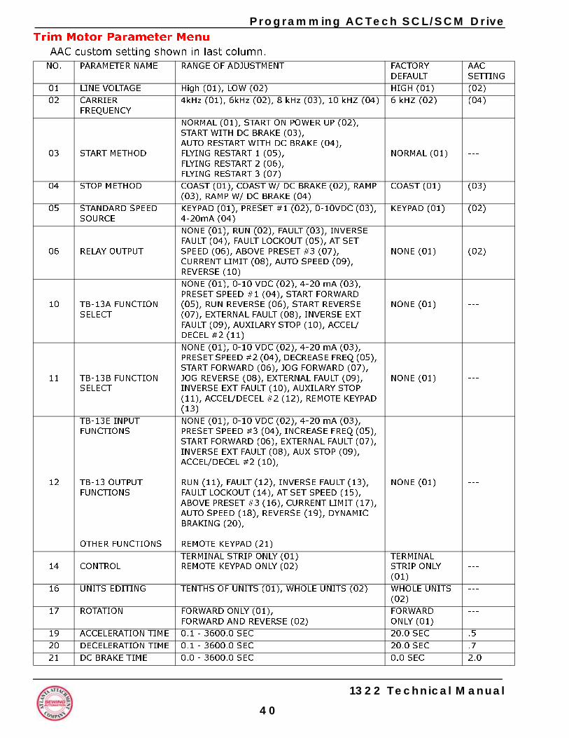
Programming ACTech SCL/SCM DriveTrim Motor Parameter Menu
AAC custom setting shown in last column.NO. PARAMETER NAME RANGE OF ADJUSTMENT FACTORY
DEFAULTAACSETTING
01 LINE VOLTAGE High (01), LOW (02) HIGH (01) (02)02 CARRIER
FREQUENCY4kHz (01), 6kHz (02), 8 kHz (03), 10 kHZ (04) 6 kHZ (02) (04)
03 START METHOD
NORMAL (01), START ON POWER UP (02),START WITH DC BRAKE (03),AUTO RESTART WITH DC BRAKE (04),FLYING RESTART 1 (05),FLYING RESTART 2 (06),FLYING RESTART 3 (07)
NORMAL (01) ---
04 STOP METHOD COAST (01), COAST W/ DC BRAKE (02), RAMP (03), RAMP W/ DC BRAKE (04)
COAST (01) (03)
05 STANDARD SPEED SOURCE
KEYPAD (01), PRESET #1 (02), 0-10VDC (03), 4-20mA (04)
KEYPAD (01) (02)
06 RELAY OUTPUT
NONE (01), RUN (02), FAULT (03), INVERSE FAULT (04), FAULT LOCKOUT (05), AT SET SPEED (06), ABOVE PRESET #3 (07), CURRENT LIMIT (08), AUTO SPEED (09), REVERSE (10)
NONE (01) (02)
10 TB-13A FUNCTION SELECT
NONE (01), 0-10 VDC (02), 4-20 mA (03), PRESET SPEED #1 (04), START FORWARD (05), RUN REVERSE (06), START REVERSE (07), EXTERNAL FAULT (08), INVERSE EXT FAULT (09), AUXILARY STOP (10), ACCEL/DECEL #2 (11)
NONE (01) ---
11 TB-13B FUNCTION SELECT
NONE (01), 0-10 VDC (02), 4-20 mA (03), PRESET SPEED #2 (04), DECREASE FREQ (05), START FORWARD (06), JOG FORWARD (07), JOG REVERSE (08), EXTERNAL FAULT (09), INVERSE EXT FAULT (10), AUXILARY STOP (11), ACCEL/DECEL #2 (12), REMOTE KEYPAD (13)
NONE (01) ---
12
TB-13E INPUT FUNCTIONS
TB-13 OUTPUT FUNCTIONS
OTHER FUNCTIONS
NONE (01), 0-10 VDC (02), 4-20 mA (03), PRESET SPEED #3 (04), INCREASE FREQ (05), START FORWARD (06), EXTERNAL FAULT (07), INVERSE EXT FAULT (08), AUX STOP (09), ACCEL/DECEL #2 (10),
RUN (11), FAULT (12), INVERSE FAULT (13), FAULT LOCKOUT (14), AT SET SPEED (15), ABOVE PRESET #3 (16), CURRENT LIMIT (17), AUTO SPEED (18), REVERSE (19), DYNAMIC BRAKING (20),
REMOTE KEYPAD (21)
NONE (01) ---
14 CONTROLTERMINAL STRIP ONLY (01)REMOTE KEYPAD ONLY (02)
TERMINAL STRIP ONLY (01)
---
16 UNITS EDITING TENTHS OF UNITS (01), WHOLE UNITS (02) WHOLE UNITS (02)
---
17 ROTATION FORWARD ONLY (01),FORWARD AND REVERSE (02)
FORWARD ONLY (01)
---
19 ACCELERATION TIME 0.1 - 3600.0 SEC 20.0 SEC .520 DECELERATION TIME 0.1 - 3600.0 SEC 20.0 SEC .721 DC BRAKE TIME 0.0 - 3600.0 SEC 0.0 SEC 2.0
1322 Technical Manual
40
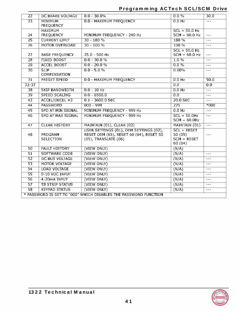
Programming ACTech SCL/SCM Drive
22 DC BRAKE VOLTAGE 0.0 - 30.0% 0.0 % 30.023 MINIMUMFREQUENCY0.0 - MAXIMUM FREQUENCY 0.0 Hz ---
24MAXIMUM FREQUENCY MINIMUM FREQUENCY - 240 Hz
SCL = 50.0 HzSCM = 60.0 Hz ---
25 CURRENT LIMIT 30 - 180 % 180 % ---26 MOTOR OVERLOAD 30 - 100 % 100 % ---
27 BASE FREQUENCY 25.0 - 500 HzSCL = 50.0 HzSCM = 60.0 Hz ---
28 FIXED BOOST 0.0 - 30.0 % 1.0 % ---29 ACCEL BOOST 0.0 - 20.0 % 0.0 % ---30 SLIP
COMPENSATION0.0 - 5.0 % 0.00% ---
31 PRESET SPEED 0.0 - MAXIMUM FREQUENCY 0.0 Hz 50.032-37 0.0 0.0
38 SKIP BANDWIDTH 0.0 - 10 Hz 0.0 Hz ---39 SPEED SCALING 0.0 - 6500.0 0.0 ---42 ACCEL/DECEL #2 0.1 - 3600.0 SEC 20.0 SEC ---44 PASSWORD 000 - 999 225 *00045 SPD AT MIN SIGNAL MINIMUM FREQUENCY - 999 Hz 0.0 Hz ---46 SPD AT MAX SIGNAL MINIMUM FREQUENCY - 999 Hz SCL = 50.0Hz
SCM = 60.0Hz---
47 CLEAR HISTORY MAINTAIN (01), CLEAR (02) MAINTAIN (01) ---
48 PROGRAMSELECTION
USER SETTINGS (01), OEM SETTINGS (02), RESET OEM (03), RESET 60 (04), RESET 50 (05), TRANSLATE (06)
SCL = RESET50 (05)SCM = RESET60 (04)
---
50 FAULT HISTORY (VIEW ONLY) (N/A) ---51 SOFTWARE CODE (VIEW ONLY) (N/A) ---52 DC BUS VOLTAGE (VIEW ONLY) (N/A) ---53 MOTOR VOLTAGE (VIEW ONLY) (N/A) ---54 LOAD VOLTAGE (VIEW ONLY) (N/A) ---55 0-10 VDC INPUT (VIEW ONLY) (N/A) ---56 4-20mA INPUT (VIEW ONLY) (N/A) ---57 TB STRIP STATUS (VIEW ONLY) (N/A) ---58 KEYPAD STATUS (VIEW ONLY) (N/A) ---
* PASSWORD IS SET TO “000” WHICH DISABLES THE PASSWORD FUNCTION
1322 Technical Manual
41
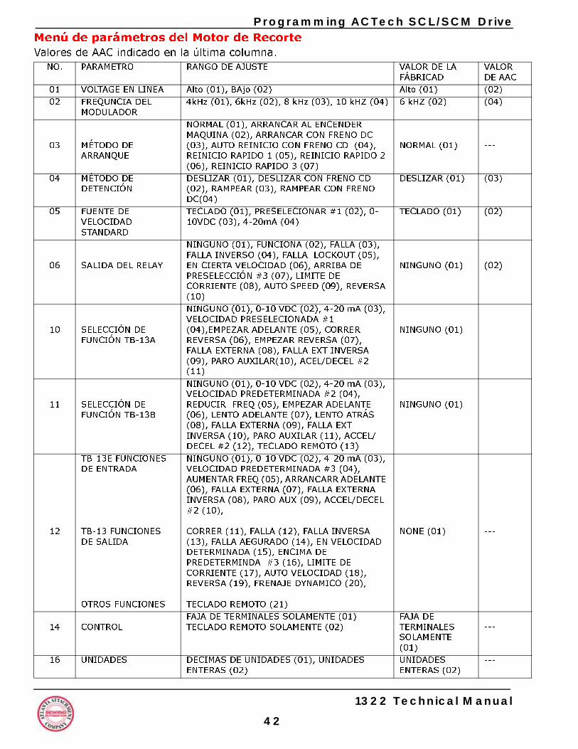
Programming ACTech SCL/SCM DriveMenú de parámetros del Motor de RecorteValores de AAC indicado en la última columna.
NO. PARAMETRO RANGO DE AJUSTE VALOR DE LA FÁBRICAD
VALOR DE AAC
01 VOLTAGE EN LINEA Alto (01), BAjo (02) Alto (01) (02)02 FREQUNCIA DEL
MODULADOR4kHz (01), 6kHz (02), 8 kHz (03), 10 kHZ (04) 6 kHZ (02) (04)
03 MÉTODO DE ARRANQUE
NORMAL (01), ARRANCAR AL ENCENDER MAQUINA (02), ARRANCAR CON FRENO DC (03), AUTO REINICIO CON FRENO CD (04), REINICIO RAPIDO 1 (05), REINICIO RAPIDO 2 (06), REINICIO RAPIDO 3 (07)
NORMAL (01) ---
04 MÉTODO DE DETENCIÓN
DESLIZAR (01), DESLIZAR CON FRENO CD (02), RAMPEAR (03), RAMPEAR CON FRENO DC(04)
DESLIZAR (01) (03)
05 FUENTE DE VELOCIDAD STANDARD
TECLADO (01), PRESELECIONAR #1 (02), 0-10VDC (03), 4-20mA (04)
TECLADO (01) (02)
06 SALIDA DEL RELAY
NINGUNO (01), FUNCIONA (02), FALLA (03), FALLA INVERSO (04), FALLA LOCKOUT (05), EN CIERTA VELOCIDAD (06), ARRIBA DE PRESELECCIÓN #3 (07), LIMITE DE CORRIENTE (08), AUTO SPEED (09), REVERSA (10)
NINGUNO (01) (02)
10 SELECCIÓN DE FUNCIÓN TB-13A
NINGUNO (01), 0-10 VDC (02), 4-20 mA (03), VELOCIDAD PRESELECIONADA #1 (04),EMPEZAR ADELANTE (05), CORRER REVERSA (06), EMPEZAR REVERSA (07), FALLA EXTERNA (08), FALLA EXT INVERSA (09), PARO AUXILAR(10), ACEL/DECEL #2 (11)
NINGUNO (01) ---
11 SELECCIÓN DE FUNCIÓN TB-13B
NINGUNO (01), 0-10 VDC (02), 4-20 mA (03), VELOCIDAD PREDETERMINADA #2 (04), REDUCIR FREQ (05), EMPEZAR ADELANTE (06), LENTO ADELANTE (07), LENTO ATRÁS (08), FALLA EXTERNA (09), FALLA EXT INVERSA (10), PARO AUXILAR (11), ACCEL/ DECEL #2 (12), TECLADO REMOTO (13)
NINGUNO (01) ---
12
TB-13E FUNCIONES DE ENTRADA
TB-13 FUNCIONES DE SALIDA
OTROS FUNCIONES
NINGUNO (01), 0-10 VDC (02), 4-20 mA (03), VELOCIDAD PREDETERMINADA #3 (04), AUMENTAR FREQ (05), ARRANCARR ADELANTE (06), FALLA EXTERNA (07), FALLA EXTERNA INVERSA (08), PARO AUX (09), ACCEL/DECEL #2 (10),
CORRER (11), FALLA (12), FALLA INVERSA (13), FALLA AEGURADO (14), EN VELOCIDAD DETERMINADA (15), ENCIMA DE PREDETERMINDA #3 (16), LIMITE DE CORRIENTE (17), AUTO VELOCIDAD (18), REVERSA (19), FRENAJE DYNAMICO (20),
TECLADO REMOTO (21)
NONE (01) ---
14 CONTROLFAJA DE TERMINALES SOLAMENTE (01) TECLADO REMOTO SOLAMENTE (02)
FAJA DE TERMINALES SOLAMENTE(01)
---
16 UNIDADES DECIMAS DE UNIDADES (01), UNIDADES ENTERAS (02)
UNIDADES ENTERAS (02)
---
1322 Technical Manual
42
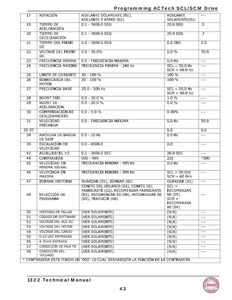
Programming ACTech SCL/SCM Drive
17 ROTACIÓN ADELANTE SOLAMENTE (01),ADELANTE Y ATRÁS (02) ADELANTE SOLAMENTE(01)
---
19 TIEMPO DE ACELERACIÓN
0.1 - 3600.0 SEG 20.0 SEG .5
20 TIEMPO DE DECELERACIÓN
0.1 - 3600.0 SEG 20.0 SEG .7
21 TIEMPO DEL FRENO DC
0.0 - 3600.0 SEG 0.0 SEG 2.0
22 VOLTAGE DEL FRENO DC
0.0 - 30.0% 0.0 % 30.0
23 FRECUENCIA MINIMA 0.0 - FRECUENCIA MAXIMA 0.0 Hz ---24 FRECUENCIA MAXIMA FRECUENCIA MINIMA - 240 Hz SCL = 50.0 Hz
SCM = 60.0 Hz---
25 LIMITE DE CORIENTE 30 - 180 % 180 % ---26 SOBRECARGA DEL
MOTOR 30 - 100 % 100 % ---
27 FRECUENCIA BASE 25.0 - 500 Hz SCL = 50.0 HzSCM = 60.0 Hz
---
28 BOOST FIJO 0.0 - 30.0 % 1.0 % ---29 BOOST DE
ACELERACION0.0 - 20.0 % 0.0 % ---
30 COMPENSACIÓN DE DESLIZAMIENTO
0.0 - 5.0 % 0.00% ---
31 VELOCIDAD PRECARGA
0.0 - FRECUENCIA MÁXIMA 0.0 Hz 50.0
32-37 0.0 0.038 ANCHURA DE BANDA
DE SKIP 0.0 - 10 Hz 0.0 Hz ---
39 ESCALACIÓN DE VELOCIDAD
0.0 - 6500.0 0.0 ---
42 ACCEL/DECEL #2 0.1 - 3600.0 SEC 20.0 SEC ---44 CONTRASEÑA 000 - 999 225 *00045 VELOCIDAD EN
MINIMA SIGNAL FRECUANCIA MINIMA - 999 Hz 0.0 Hz ---
46 VELOCIADA EN MAXIMA
FRECUANCIA MINIMA - 999 Hz SCL = 50.0Hz SCM = 60.0Hz
---
47 BORRAR HISTORIA GUARDAR (01), BORRAR (02) GUARDAR (01) ---
48 SELECCIÓN DEPROGRAMA
CONFIG DEL USUARIO (01), CONFIG DEL FABRICANTE (02), RECOMENZAR FABRICANTE (03), RECOMENZAR 60 (04), RECOMENZAR 50 (05), TRADUCIR (06)
SCL = RECOMENZAR 50 (05) SCM = RECOMENZAR 60 (04)
---
50 HISTORIA DE FALLAS (VER SOLAMENTE) (N/A) ---51 CÓDIGO DE SOFTWARE (VER SOLAMENTE) (N/A) ---52 VOLTAGE DEL BUS DC (VER SOLAMENTE) (N/A) ---53 VOLTAGE DEL MOTOR (VER SOLAMENTE) (N/A) ---54 VOLTAGE DEL CARGO (VER SOLAMENTE) (N/A) ---55 0-10 VDC ENTRADAA (VER SOLAMENTE) (N/A) ---56 4-20mA ENTRADA (VER SOLAMENTE) (N/A) ---57 CONDICIÓN DE FAJA TB (VER SOLAMENTE) (N/A) ---58 CONDICIÓN DEL
TECLADO (VER SOLAMENTE) (N/A) ---
* CONTRASEÑA ESTÁ FIJADO EN "000" LO CUAL DESHABILITA LA FUNCIÓN DE LA CONTRASEÑA
1322 Technical Manual
43
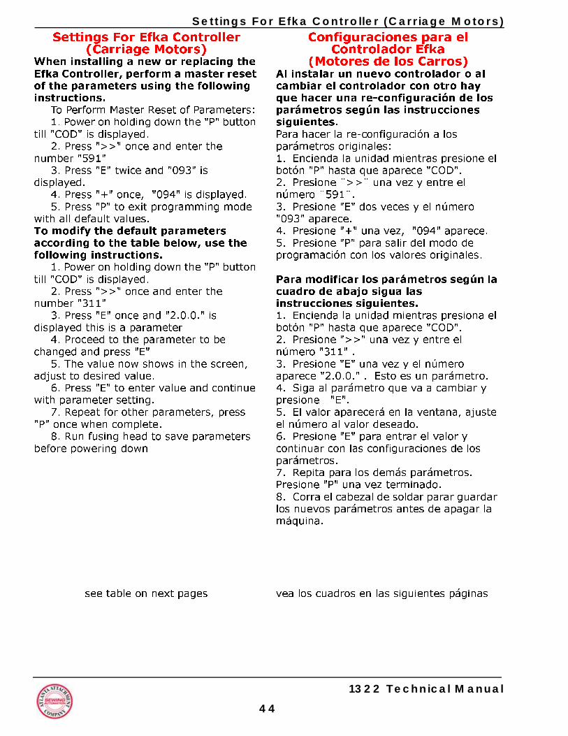
Settings FoSettings For Efka Controller
(Carriage Motors)When installing a new or replacing the Efka Controller, perform a master reset of the parameters using the following instructions.
To Perform Master Reset of Parameters:1. Power on holding down the "P" button
till "COD" is displayed.2. Press ">>" once and enter the
number "591"3. Press "E" twice and "093" is
displayed.4. Press "+" once, "094" is displayed.5. Press "P" to exit programming mode
with all default values.To modify the default parameters according to the table below, use the following instructions.
1. Power on holding down the "P" button till "COD" is displayed.
2. Press ">>" once and enter the number "311"
3. Press "E" once and "2.0.0." is displayed this is a parameter
4. Proceed to the parameter to be changed and press "E"
5. The value now shows in the screen, adjust to desired value.
6. Press "E" to enter value and continue with parameter setting.
7. Repeat for other parameters, press "P" once when complete.
8. Run fusing head to save parameters before powering down
see table on next pages
4
r Efka Controller (Carriage Motors)Configuraciones para el
Controlador Efka(Motores de los Carros)
Al instalar un nuevo controlador o al cambiar el controlador con otro hay que hacer una re-configuración de los parámetros según las instrucciones siguientes. Para hacer la re-configuración a los parámetros originales: 1. Encienda la unidad mientras presione el botón "P" hasta que aparece "COD".2. Presione ¨>>¨ una vez y entre el número ¨591¨.3. Presione "E" dos veces y el número "093" aparece. 4. Presione "+" una vez, "094" aparece.5. Presione "P" para salir del modo de programación con los valores originales.
Para modificar los parámetros según la cuadro de abajo sigua las instrucciones siguientes.1. Encienda la unidad mientras presiona el botón "P" hasta que aparece "COD".2. Presione ">>" una vez y entre el número "311" .3. Presione "E" una vez y el número aparece "2.0.0." . Esto es un parámetro.4. Siga al parámetro que va a cambiar y presione "E". 5. El valor aparecerá en la ventana, ajuste el número al valor deseado.6. Presione "E" para entrar el valor y continuar con las configuraciones de los parámetros.7. Repita para los demás parámetros. Presione "P" una vez terminado.8. Corra el cabezal de soldar parar guardar los nuevos parámetros antes de apagar la máquina.
vea los cuadros en las siguientes páginas
1322 Technical Manual
4
Settings Fo
Settings For Efka Controller(Carriage Motors)
PARAMETER RANGE VALUE DESC290 0 Mode
FIRS110 7-39 30 Posit111 0-999 400 Maxi119 1-3 1 Linea153 0-50 35 Brak161 0-1 0-CCW Moto207 1-55 1 Brak220 1-55 1 Acce240 0-56 55 Enab270 0-5 5 No h272 020-255 100 Drive
pulle
PARÁMETRO RANGO VALOR DESC290 0 Modo
PARÁ110 7-39 30 Veloc111 0-999 400 Veloc119 1-3 1 Acele153 0-50 35 Pote161 0-1 0-CCW Rota207 1-55 1 Fren220 1-55 1 Acele240 0-56 55 Habi270 0-5 5 Sin s272 020-255 100 Prop
Front panel LED's: Luces (LED)
LED 1: Off LED 1: ALED 2: Off LED 2: ALED 3: Off LED 3: ALED 4: Off LED 4: ALED 5: Off LED 5: ALED 6: Off LED 6: ALED 7: Off LED 7: ALED 8: Off LED 8: A
1322 Technical Manual
4
r Efka Controller (Carriage Motors)
RIPTION of operation. MUST SET THIS PARAMETER T!ioning Speedmum speed when "129" is 0, 1, or 2.r acceleration
ing power at standstillr rotationinglerationle reverse run of motor with input 1andwheel sensor ratio between motor pulley and handwheel y.
RIPCIÓN de operación. TIENE QUE INGRESAR ESTE METRO PRIMERO! idad de Posicionamientoidad Maxima cuando "129" es 0, 1, o 2. ración Linear
ncia de frenaje sin movimientoción del motorajeración
lita rotación atrás con valor 1 ensor de rotaciónorción entre polea del motor y del cabezal.
en el panel delantero:
pagadopagadopagadopagadopagadopagadopagadopagado
5
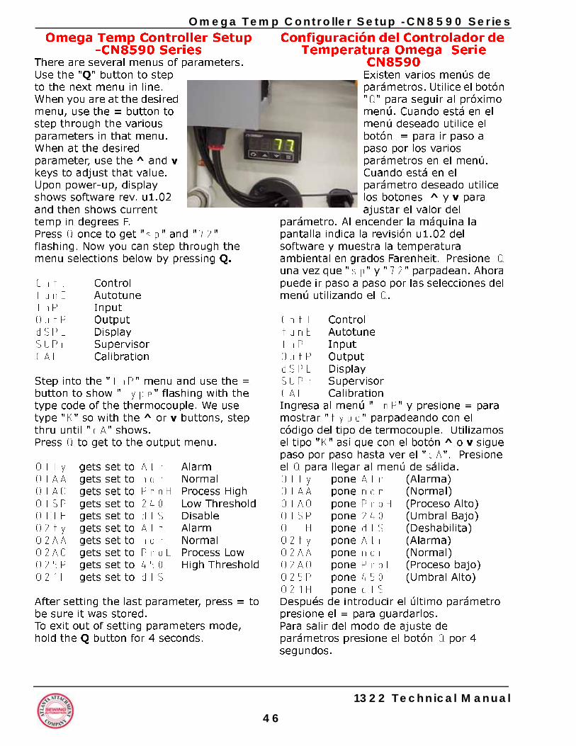
4
p Controller Setup -CN8590 SeriesConfiguración del Controlador de
Temperatura Omega Serie CN8590Existen varios menús de parámetros. Utilice el botón "Q" para seguir al próximo menú. Cuando está en el menú deseado utilice el botón = para ir paso a paso por los varios parámetros en el menú. Cuando está en el parámetro deseado utilice los botones ^ y v para ajustar el valor del
parámetro. Al encender la máquina la pantalla indica la revisión u1.02 del software y muestra la temperatura ambiental en grados Farenheit. Presione Q una vez que "sp" y "72" parpadean. Ahora puede ir paso a paso por las selecciones del menú utilizando el Q.
Cntl ControltunE AutotuneInP InputOutP OutputdSPL DisplaySUPr SupervisorCAL Calibration Ingresa al menú "InP" y presione = para mostrar "type" parpadeando con el código del tipo de termocouple. Utilizamos el tipo "K" así que con el botón ^ o v sigue paso por paso hasta ver el "cA". Presione el Q para llegar al menú de sálida.OIty pone Alr (Alarma)OIAA pone nor (Normal)OIAO pone ProH (Proceso Alto)OISP pone 240 (Umbral Bajo)OIIH pone dIS (Deshabilita)O2ty pone Alr (Alarma)O2AA pone nor (Normal)O2AO pone ProL (Proceso bajo)O25P pone 450 (Umbral Alto)O21H pone dISDespués de introducir el último parámetro presione el = para guardarlos.Para salir del modo de ajuste de parámetros presione el botón Q por 4 segundos.
Omega TemOmega Temp Controller Setup
-CN8590 SeriesThere are several menus of parameters. Use the "Q" button to step to the next menu in line. When you are at the desired menu, use the = button to step through the various parameters in that menu. When at the desired parameter, use the ^ and v keys to adjust that value.Upon power-up, display shows software rev. u1.02 and then shows current temp in degrees F.Press Q once to get "sp" and "72" flashing. Now you can step through the menu selections below by pressing Q.
Cntl ControltunE AutotuneInP InputOutP OutputdSPL DisplaySUPr SupervisorCAL Calibration
Step into the "InP" menu and use the = button to show "type" flashing with the type code of the thermocouple. We use type "K" so with the ^ or v buttons, step thru until "cA" shows.Press Q to get to the output menu.
OIty gets set to Alr AlarmOIAA gets set to nor NormalOIAO gets set to ProH Process HighOISP gets set to 240 Low ThresholdOIIH gets set to dIS DisableO2ty gets set to Alr AlarmO2AA gets set to nor NormalO2AO gets set to ProL Process LowO25P gets set to 450 High ThresholdO21H gets set to dIS
After setting the last parameter, press = to be sure it was stored.To exit out of setting parameters mode, hold the Q button for 4 seconds.
1322 Technical Manual
6
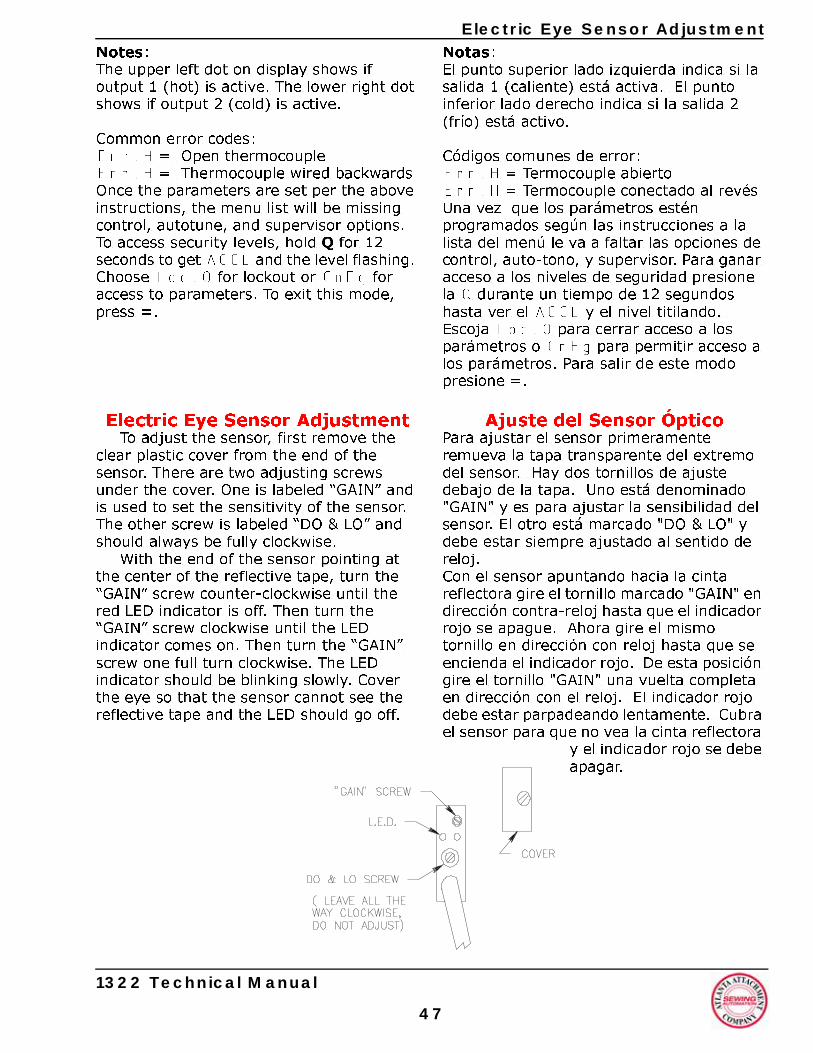
Electric Eye Sensor Adjustment
Notes:The upper left dot on display shows if output 1 (hot) is active. The lower right dot shows if output 2 (cold) is active.Common error codes:Err.H = Open thermocoupleErr.H = Thermocouple wired backwardsOnce the parameters are set per the above instructions, the menu list will be missing control, autotune, and supervisor options.To access security levels, hold Q for 12 seconds to get ACCL and the level flashing. Choose Loc.O for lockout or CnFg for access to parameters. To exit this mode, press =.
Electric Eye Sensor AdjustmentTo adjust the sensor, first remove the
clear plastic cover from the end of the sensor. There are two adjusting screws under the cover. One is labeled “GAIN” and is used to set the sensitivity of the sensor. The other screw is labeled “DO & LO” and should always be fully clockwise.
With the end of the sensor pointing at the center of the reflective tape, turn the “GAIN” screw counter-clockwise until the red LED indicator is off. Then turn the “GAIN” screw clockwise until the LED indicator comes on. Then turn the “GAIN” screw one full turn clockwise. The LED indicator should be blinking slowly. Cover the eye so that the sensor cannot see the reflective tape and the LED should go off.
1322 Technical Manual
4
Notas:El punto superior lado izquierda indica si la salida 1 (caliente) está activa. El punto inferior lado derecho indica si la salida 2 (frío) está activo.
Códigos comunes de error:Err.H = Termocouple abiertoErr.H = Termocouple conectado al revésUna vez que los parámetros estén programados según las instrucciones a la lista del menú le va a faltar las opciones de control, auto-tono, y supervisor. Para ganar acceso a los niveles de seguridad presione la Q durante un tiempo de 12 segundos hasta ver el ACCL y el nivel titilando. Escoja Loc.O para cerrar acceso a los parámetros o CnFg para permitir acceso a los parámetros. Para salir de este modo presione =.
Ajuste del Sensor ÓpticoPara ajustar el sensor primeramente remueva la tapa transparente del extremo del sensor. Hay dos tornillos de ajuste debajo de la tapa. Uno está denominado "GAIN" y es para ajustar la sensibilidad del sensor. El otro está marcado "DO & LO" y debe estar siempre ajustado al sentido de reloj.Con el sensor apuntando hacia la cinta reflectora gire el tornillo marcado "GAIN" en dirección contra-reloj hasta que el indicador rojo se apague. Ahora gire el mismo tornillo en dirección con reloj hasta que se encienda el indicador rojo. De esta posición gire el tornillo "GAIN" una vuelta completa en dirección con el reloj. El indicador rojo debe estar parpadeando lentamente. Cubra el sensor para que no vea la cinta reflectora
y el indicador rojo se debe apagar.
7
4
Reflective Tape Maintenance
Part # Description Qty Pg
Mantenimiento de la Cinta Reflectiva
Utilice un trapo suave para limpieza. No utilice soluciones químicas ni abrasivas para limpiarla. Evite contacto con aceite o líquidos. No toque la cinta con sus dedos. Si la cinta está sucia u opaca es posible que el ojo no funcione correctamente.
Mantenimiento1. Revise el separador de agua cada turno
- vacielo en caso que sea necesariod. 2. Limpe la máquina diareamente al
terminar cada turno.- Limpie los sensores ópticos con un trapo suave limpio y seco.- Con aire comprimido limpie el polvo polyeteraneo del area de las cabeza de soldar.
3. Revise los filtros de aire cada semana y reemplaze los elementos cada 6 meses.
4. En caso de falla del soldador contacte Atlanta Attachment Company para obtener un repuesto.
Lista de RepuestosRecomendados
Contacte división de ventas de AAC para pedir repuestos. Tel: 770-963-7369 Fax: 770-963-7641 Internet: www.atlatt.com AAC Parte # SP1322 Paquete de repuestos para instalaciones domesticas AAC Parte # SP1322I Paquete de repuestos para instalaciones internacionales
AAEVQN7 Solenoid Valve 2AAVF51FM1B Air Pressure Switch 1FF3120L420A Circuit Breaker 1FFD2425F Relay 1FFT18FF100Q Electric Eye 2FFT18FF25Q Electric Eye 1GG150L050 Gear Belt 1MM133C1-25 Sharpening Stone 2MMR80C177 Blade 2
Part # Description Qty Pg
Reflective Tape MaintenanceUse a soft cloth for cleaning. Do not use chemicals or abrasives to clean it.Avoid any contact with oils and liquids. Do not touch the tape with bare fingers.If tape is dirty or opaque, the eye may not function correctly.
Maintenance1. Check water separator at beginning of
each shift - drain if necessary.2. Clean machine daily at the end of every
shift.- Wipe all photo eye lenses with clean, nonabrasive, dry cloth.- Use blow-off hose to get rid of excess polyethelene dust from fusing head areas.
3. Check air filters weekly, replace filter elements once every 6 months.
4. In case of heat gun failure, contact Atlanta Attachment Company for replacement.
Recommended Spare Parts ListContact AAC’s sales department to order replacement parts.Phone: 770-963-7369Fax: 770-963-7641Email: [email protected]: www.atlatt.com
1278-7055D Prox Switch w/ Plug 21322-005 Thermocouple Assy 21322180 Leister Gun 21322660 Lower Clamp Assy 1A-2014-39 Micro Switch 2AA198-503B Regulator, 0-30 PSI 1AA198-508 Regulator, 0-160 PSI 1AAC7DP-6 Air Cylinder 2AACXSM2060 Air Cylinder 1
1322 Technical Manual
8

Assembly Drawings & Parts Lists
Assembly Drawings & Parts Lists
The materials contained herein are confidential and proprietary information of Atlanta Attachment Company. In addition to any confidentiality and non-disclosure obligations that currently exist between you and Atlanta Attachment Company, your use of these materials serves as an acknowledgment of the confidential and proprietary nature of these materials and your duty not to make any unauthorized use or disclosure of these materials.
Lista De Partes
Los materiales contenidos en este documento son confidenciales y propiedad de Atlanta Attachment Company. Además de cualquier obligación de seguridad y confidencia que puedan exisitir entre usted y Atlanta Attachment Company, su uso de estos materiales sirve como reconocimiento de la naturaleza de confidencia y propiedad de los materiales y su obligación para hacer ningún uso o reproducción de los mismos.
1322 Technical Manual
49
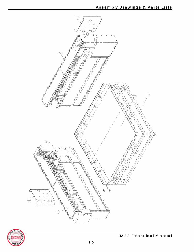
Assembly Drawings & Parts Lists
1322 Technical Manual
50

Assembly Drawings & Parts Lists
11322 Unibody Fusing Workstation
1 1322500 Base Frame Assy 1 532 1322600 Table Top Assy 1 553 1322700B Sub-Frame 2 Assy 1 594 1322700A Sub-Frame 1 Assy 1 575 1322950 Control Box 1 16 1322951 Control Box 2 17 1322953 Cable Package 1
8 1322960 Control Panel Assembly 19 1322-PD1 Pneumatic Diagram AR10 1322-WD1 Wiring Diagram AR11 1322-WD2 Wiring Diagram AR12 LI22370511M Safety Mat 2Rev. 1
# Part # Description Qty Pg # Part # Description Qty Pg
1322 Technical Manual
51
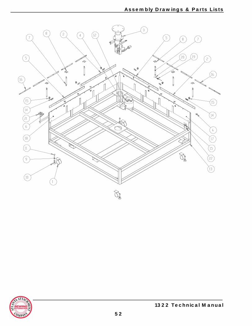
Assembly Drawings & Parts Lists
1322 Technical Manual
52
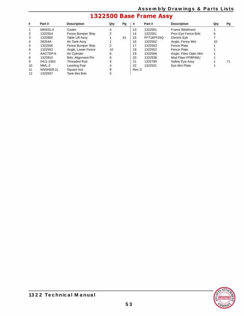
Assembly Drawings & Parts Lists
1322500 Base Frame Assy
1 MM431-4 Caster 42 1322554 Fence Bumper Strip 23 1322800 Table Lift Assy 1 614 26254A Air Tank Assy 15 1322556 Fence Bumper Strip 26 1322563 Angle, Lower Fence 107 AAC7DP-6 Air Cylinder 68 1322810 Brkt, Alignment Pin 69 0411-1063 Threaded Rod 410 MML-2 Leveling Pad 411 NNSH5/8-11 Square Nut 812 1322557 Tank Mnt Brkt 3
13 1322501 Frame Weldment 114 1322551 Prox Eye Fence Brkt 615 FFT18FF25Q Electric Eye 716 1322562 Angle, Fence Mnt 1017 1322553 Fence Plate 118 1322552 Fence Plate 119 1322566 Angle, Fiber Optic Mnt 120 1322538 Mod Fiber-FFBP46U 121 1322790 Safety Eye Assy 1 7122 1322531 Eye Mnt Plate 1Rev. 0
# Part # Description Qty Pg # Part # Description Qty Pg
1322 Technical Manual
53
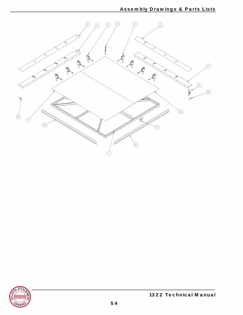
Assembly Drawings & Parts Lists
1322 Technical Manual
54

Assembly Drawings & Parts Lists
1322600 Table Top Assembly
1 1322601 Table Top Weldment 12 1322651 Table Extension 13 1322656 Table Extension 14 1322660 Lower Clamp Assy 9 635 1322657 Extension Cover 16 1322652 Extension Cover 17 1322640 Table Cover 1
8 1322641 Table Cover 19 1322680 Stop Switch Mnt Brkt 110 1322920 Bumper, Table Corner 211 1322540 Flag Assy 112 1322610 Table Edge Cover 113 1322619 Table Edge Cover 1Rev. 1
# Part # Description Qty Pg # Part # Description Qty Pg
1322 Technical Manual
55
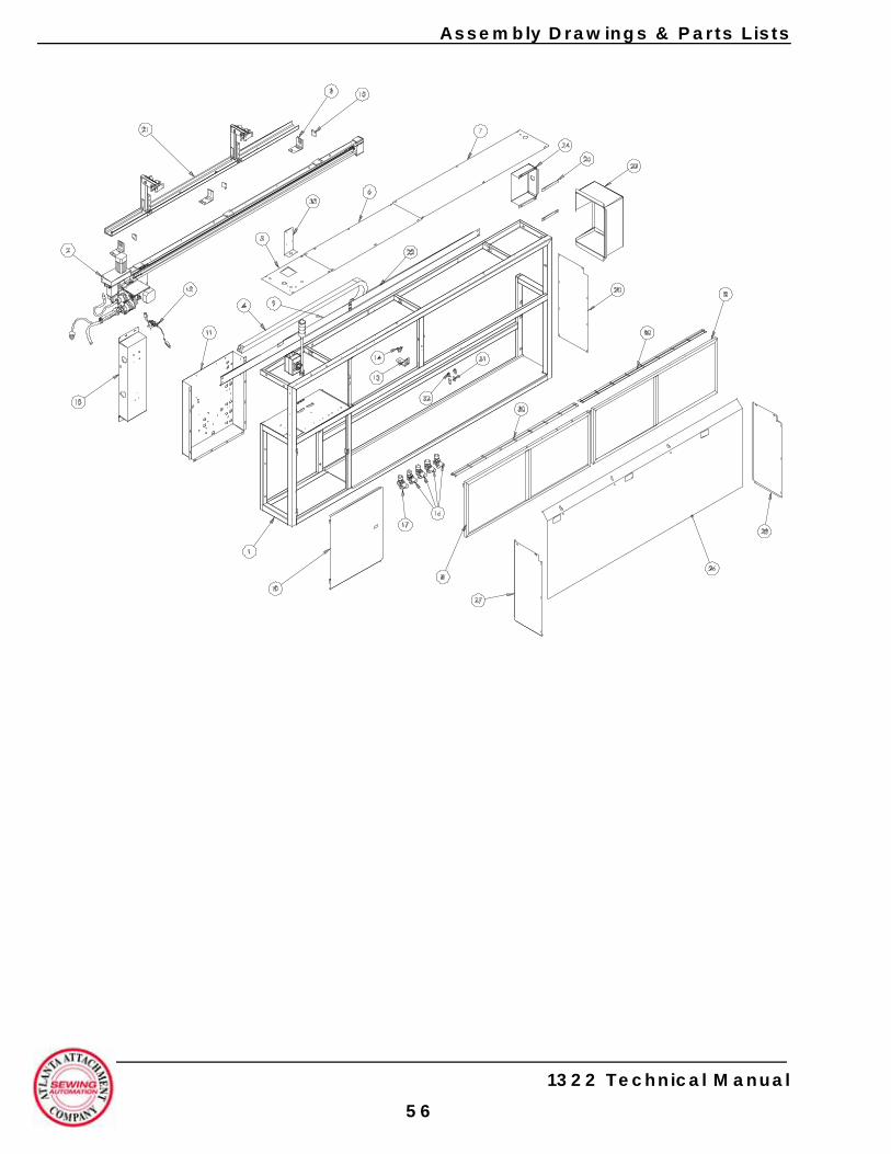
Assembly Drawings & Parts Lists
1322 Technical Manual
56
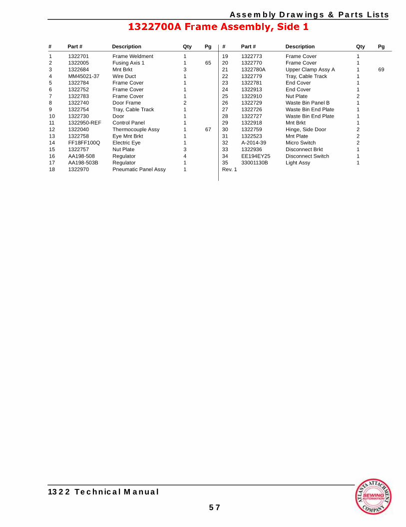
Assembly Drawings & Parts Lists
1322700A Frame Assembly, Side 1
1 1322701 Frame Weldment 12 1322005 Fusing Axis 1 1 653 1322684 Mnt Brkt 34 MM45021-37 Wire Duct 15 1322784 Frame Cover 16 1322752 Frame Cover 17 1322783 Frame Cover 18 1322740 Door Frame 29 1322754 Tray, Cable Track 110 1322730 Door 111 1322950-REF Control Panel 112 1322040 Thermocouple Assy 1 6713 1322758 Eye Mnt Brkt 114 FF18FF100Q Electric Eye 115 1322757 Nut Plate 316 AA198-508 Regulator 417 AA198-503B Regulator 118 1322970 Pneumatic Panel Assy 1
19 1322773 Frame Cover 120 1322770 Frame Cover 121 1322780A Upper Clamp Assy A 1 6922 1322779 Tray, Cable Track 123 1322781 End Cover 124 1322913 End Cover 125 1322910 Nut Plate 226 1322729 Waste Bin Panel B 127 1322726 Waste Bin End Plate 128 1322727 Waste Bin End Plate 129 1322918 Mnt Brkt 130 1322759 Hinge, Side Door 231 1322523 Mnt Plate 232 A-2014-39 Micro Switch 233 1322936 Disconnect Brkt 134 EE194EY25 Disconnect Switch 135 33001130B Light Assy 1Rev. 1
# Part # Description Qty Pg # Part # Description Qty Pg
1322 Technical Manual
57
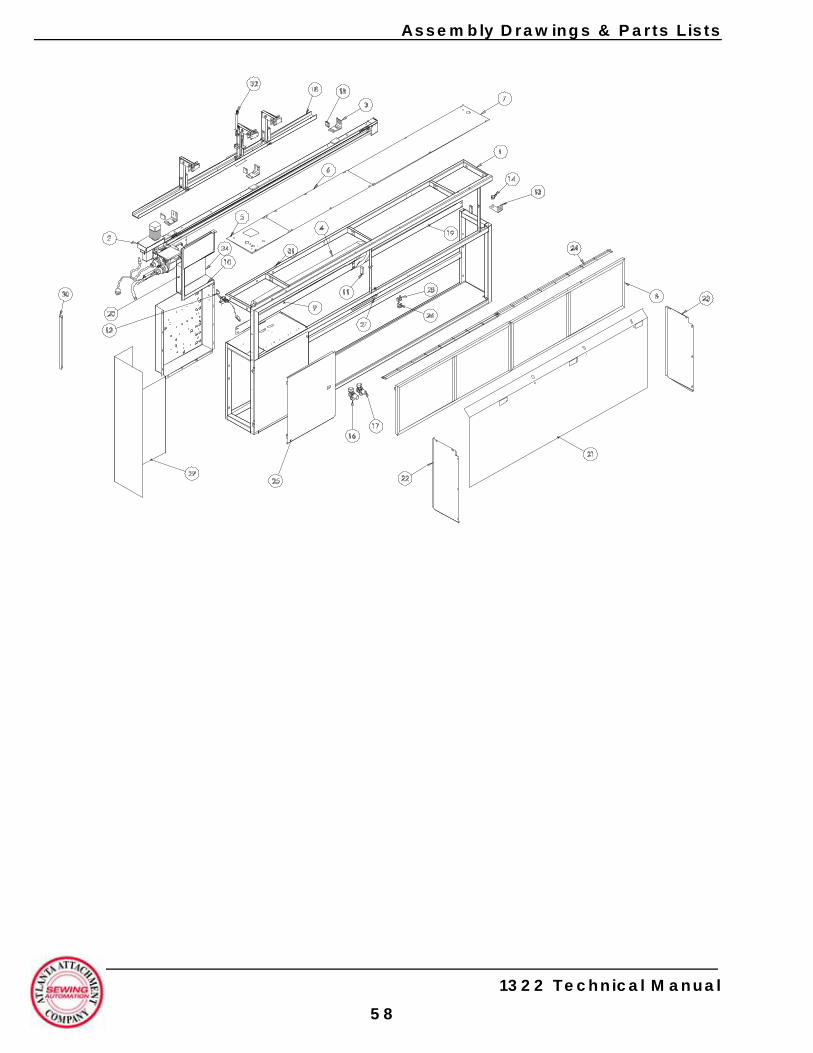
Assembly Drawings & Parts Lists
1322 Technical Manual
58
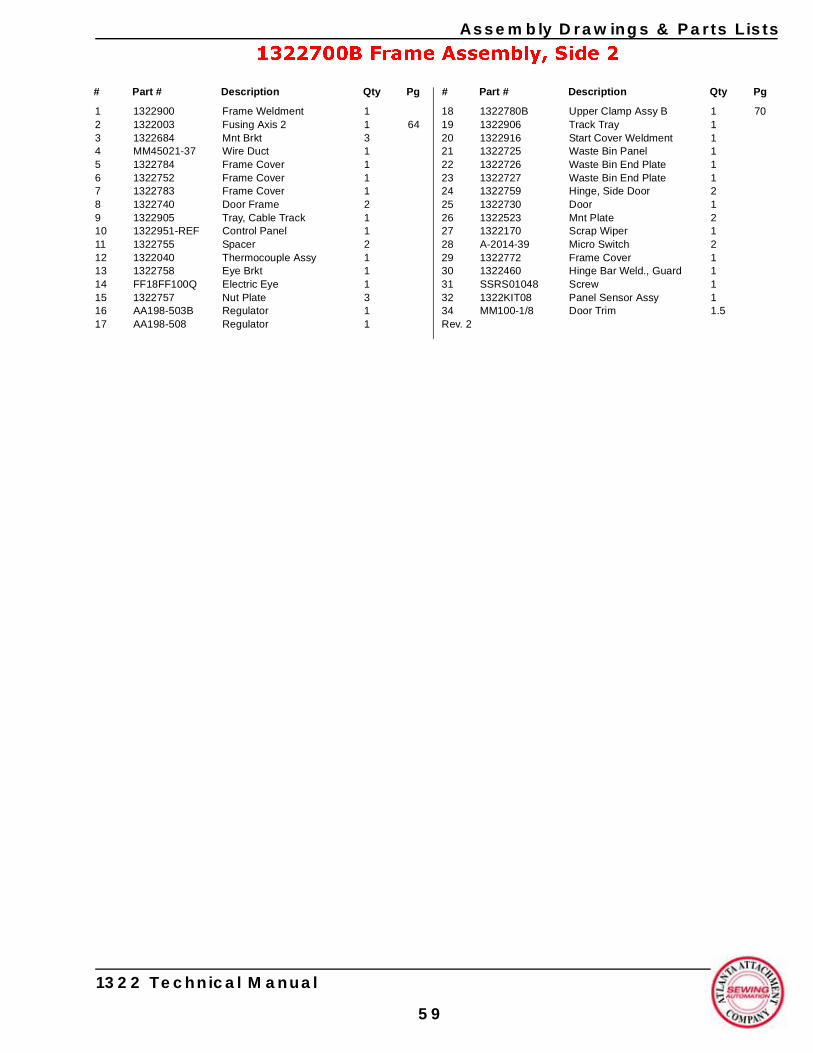
Assembly Drawings & Parts Lists
1322700B Frame Assembly, Side 2
1 1322900 Frame Weldment 12 1322003 Fusing Axis 2 1 643 1322684 Mnt Brkt 34 MM45021-37 Wire Duct 15 1322784 Frame Cover 16 1322752 Frame Cover 17 1322783 Frame Cover 18 1322740 Door Frame 29 1322905 Tray, Cable Track 110 1322951-REF Control Panel 111 1322755 Spacer 212 1322040 Thermocouple Assy 113 1322758 Eye Brkt 114 FF18FF100Q Electric Eye 115 1322757 Nut Plate 316 AA198-503B Regulator 117 AA198-508 Regulator 1
18 1322780B Upper Clamp Assy B 1 7019 1322906 Track Tray 120 1322916 Start Cover Weldment 121 1322725 Waste Bin Panel 122 1322726 Waste Bin End Plate 123 1322727 Waste Bin End Plate 124 1322759 Hinge, Side Door 225 1322730 Door 126 1322523 Mnt Plate 227 1322170 Scrap Wiper 128 A-2014-39 Micro Switch 229 1322772 Frame Cover 130 1322460 Hinge Bar Weld., Guard 131 SSRS01048 Screw 132 1322KIT08 Panel Sensor Assy 134 MM100-1/8 Door Trim 1.5Rev. 2
# Part # Description Qty Pg # Part # Description Qty Pg
1322 Technical Manual
59
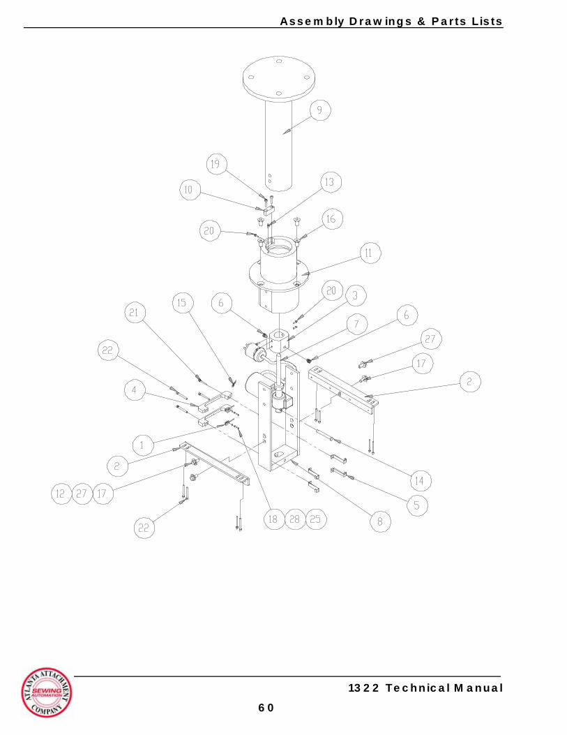
Assembly Drawings & Parts Lists
1322 Technical Manual
60
Assembly Drawings & Parts Lists
1322800 Table Lift Assembly
1 1278-7055D Prox Switch 22 1322525 Support Brkt 23 1322801 Acuator Pivot 14 1322803 Brkt, Prox Switch 25 1322804 Anchor Clamp 46 1322805 Pin, Column Retaining 27 1322940 Actuator Assembly 18 13452005 Actuator Frame Assy 19 13452009 Column Assy 110 13452016 Anti-Rotation Block 111 13452020A Column Hub Assy 112 FW0.375 413 MM1095K44 Grease Fitting 114 MM98306A285 Clevis Pin 115 MM98335A04 Spring Clip 1
16 SSFC45064 Screw, Flat Allen 417 SSHC25064 Screw, Hex Cap 418 SSPS50024 Screw, Pan Head 219 SSSC01064 Screw, Socket Cap 220 SSSC90032 Screw, Socket Cap 521 SSSC98096 Screw, Socket Cap 122 SSSC98128 Screw, Socket Cap 1123 SSSS01016 Screw, Socket Set 224 WWF10 Flat Washer 825 WWF4 Flat Washer 226 WWL10 Lock Washer 827 WWL3/8 Lock Washer 428 WWL4 Lock Washer 2Rev. 0
# Part # Description Qty Pg # Part # Description Qty Pg
1322 Technical Manual
61
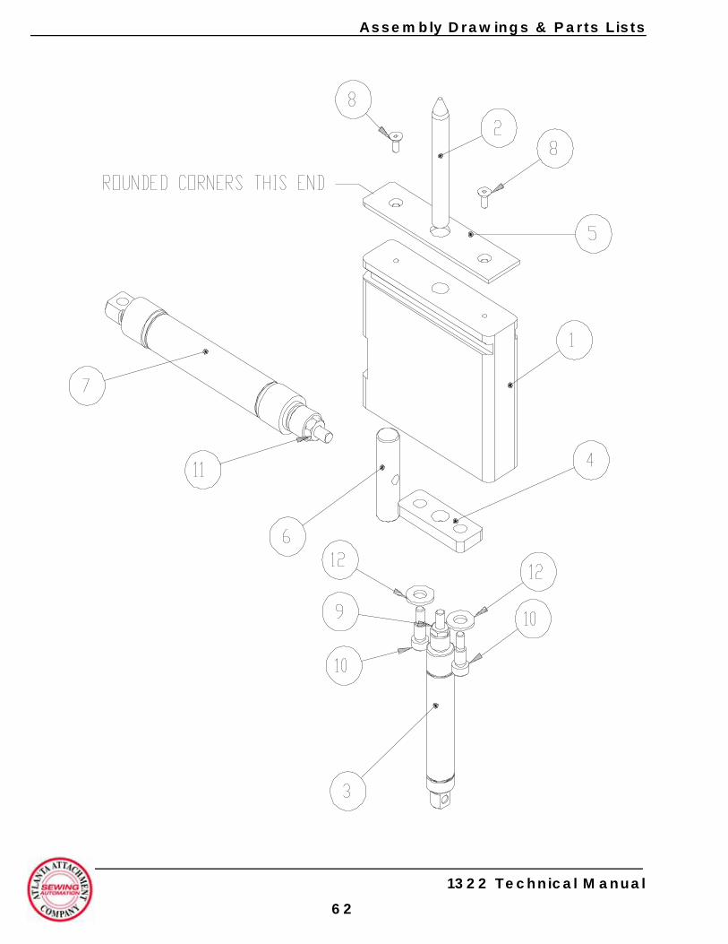
Assembly Drawings & Parts Lists
1322 Technical Manual
62

Assembly Drawings & Parts Lists
1322660 Lower Clamp Assembly
1 1322661 Clamp Block 12 1322667 Pin, Lower Clamp 13 AAC8DP-1.5 Air Cylinder 14 1322665 Mnt Plate 15 1322645 Spacer 16 1322664 Barrel Nut 17 AAC7DP-2 Air Cylinder 1
8 SSFC80024 Screw, Flat Allen 29 NNJ10-32 Jam Nut 110 SSAS016024 Shoulder Bolt 211 NNJ1/4-28 Jam Nut 112 WWF1/4 Flat Washer 2Rev. 2
# Part # Description Qty Pg # Part # Description Qty Pg
1322 Technical Manual
63
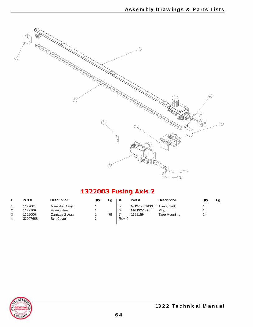
Assembly Drawings & Parts Lists
1322003 Fusing Axis 2
1 1322001 Main Rail Assy 12 1322100 Fusing Head 13 1322006 Carriage 2 Assy 1 794 32007658 Belt Cover 2
5 GG2250L100ST Timing Belt 16 MM132-1496 Plug 17 1322159 Tape Mounting 1Rev. 0
# Part # Description Qty Pg # Part # Description Qty Pg
1322 Technical Manual
64
Assembly Drawings & Parts Lists
1322005 Fusing Axis 1
1 1322001 Main Rail Assy 1 732 1322100 Fusing Head 1 753 1322021 Carriage 1 Assy 1 77
4 GG2250L100ST Timing Belt 15 32007658 Belt Cover 26 MM132-1496 Plug 1Rev. 0
# Part # Description Qty Pg # Part # Description Qty Pg
1322 Technical Manual
65
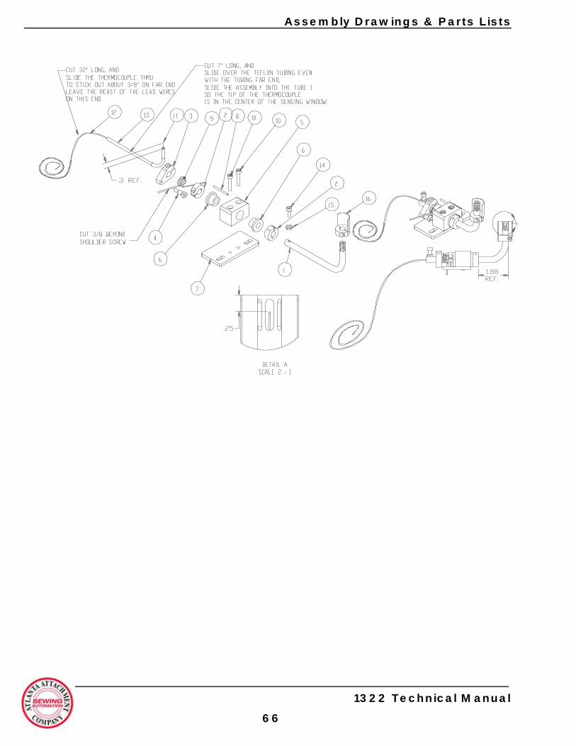
Assembly Drawings & Parts Lists
1322 Technical Manual
66

Assembly Drawings & Parts Lists
1322040 Thermocouple Assembly
1 1322041 Tube 12 CCCL6F Clamp Collar 23 33005667 Spring Clamp 14 SSAS016024 Screw, Allen Shoulder 15 1322042 Pivot Block 16 BBRF061004 Rulan Bearing 27 1322043 Mount Plate 18 IIS008X080 Spring Pin 19 RRLTR048J4M Torsion Spring 1
10 SSSC98064 Screw, Socket Cap 211 1322-005 Thermocouple, Omega 112 EE37N1586 Teflon Tubing 113 MM8832K54 Silicone Sleeve 114 SSSC98032 Screw, Socket Cap 115 NNJ10-32 Jam Nut 116 1322045 Air Deflector 1Rev. 0
# Part # Description Qty Pg # Part # Description Qty Pg
1322 Technical Manual
67
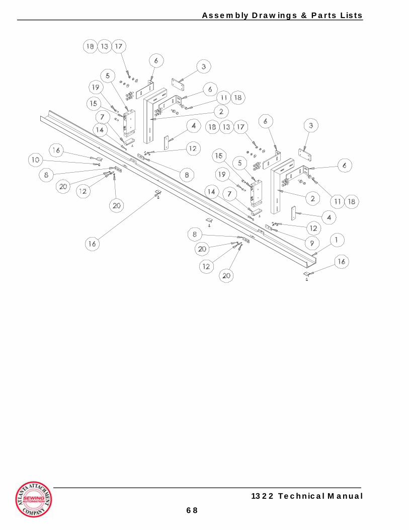
Assembly Drawings & Parts Lists
1322 Technical Manual
68

Assembly Drawings & Parts Lists
1322780A Upper Clamp Assembly A
1 1322765 Upper Clamp Rail 12 1322760 Cylinder Mnt Brkt 23 1322764 Nut Plate 24 1322766 Nut Plate 25 AACXSM2060 Air Cylinder 26 1322763 Mnt Plate 47 1322768 Pivot Block 28 1322769 Pivot Bearing 39 1322788 Pivot Bearing 110 SSBC90032 Screw, Button Cap 411 SSHC01112 Screw, Hex Cap 12
12 WWF1/4 Flat Washer 1613 SSAS016032 Screw, Allen Shoulder 414 WWL1/4 Lock Washer 415 SSPS90016 Screw, Pan Head 816 SSFC98048 Screw, Flat Allen 417 AAQME-5-10 Male Elbow 418 1322290 Plate, Bent Pin 419 NNH1/4-20 Hex Nut 420 SSSC98128 Screw, Socket Cap 4Rev. 3
# Part # Description Qty Pg # Part # Description Qty Pg
1322 Technical Manual
69
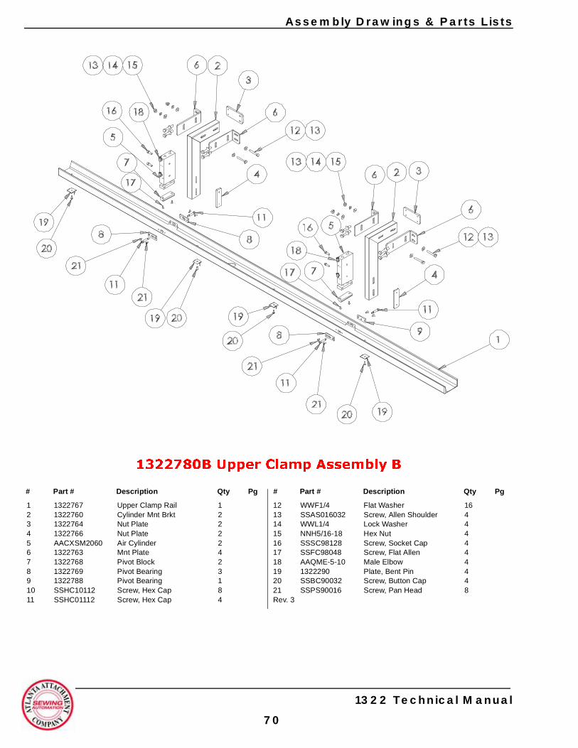
Assembly Drawings & Parts Lists
1322780B Upper Clamp Assembly B
1 1322767 Upper Clamp Rail 12 1322760 Cylinder Mnt Brkt 23 1322764 Nut Plate 24 1322766 Nut Plate 25 AACXSM2060 Air Cylinder 26 1322763 Mnt Plate 47 1322768 Pivot Block 28 1322769 Pivot Bearing 39 1322788 Pivot Bearing 110 SSHC10112 Screw, Hex Cap 811 SSHC01112 Screw, Hex Cap 4
12 WWF1/4 Flat Washer 1613 SSAS016032 Screw, Allen Shoulder 414 WWL1/4 Lock Washer 415 NNH5/16-18 Hex Nut 416 SSSC98128 Screw, Socket Cap 417 SSFC98048 Screw, Flat Allen 418 AAQME-5-10 Male Elbow 419 1322290 Plate, Bent Pin 420 SSBC90032 Screw, Button Cap 421 SSPS90016 Screw, Pan Head 8Rev. 3
# Part # Description Qty Pg # Part # Description Qty Pg
1322 Technical Manual
70
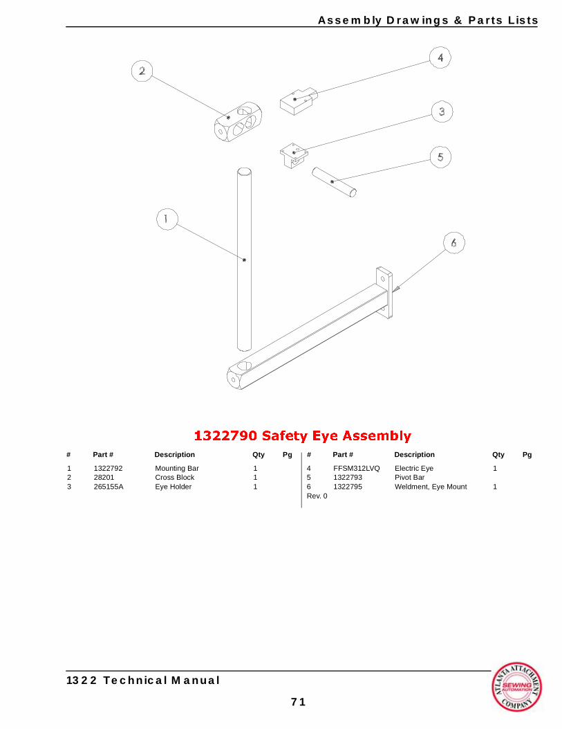
Assembly Drawings & Parts Lists
1322790 Safety Eye Assembly
1 1322792 Mounting Bar 12 28201 Cross Block 13 265155A Eye Holder 1
4 FFSM312LVQ Electric Eye 15 1322793 Pivot Bar6 1322795 Weldment, Eye Mount 1Rev. 0
# Part # Description Qty Pg # Part # Description Qty Pg
1322 Technical Manual
71
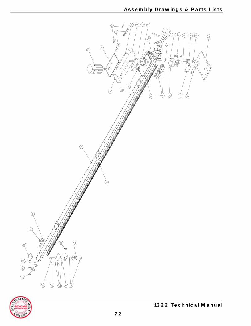
Assembly Drawings & Parts Lists
1322 Technical Manual
72
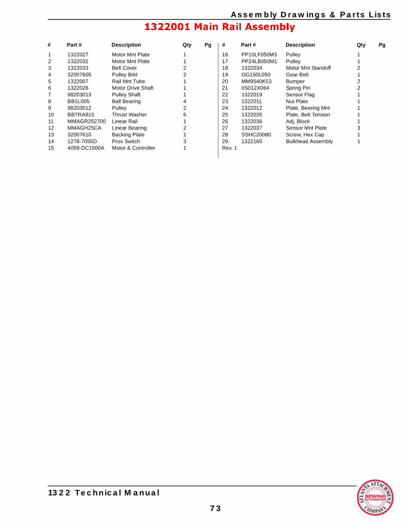
Assembly Drawings & Parts Lists
1322001 Main Rail Assembly
1 1322027 Motor Mnt Plate 12 1322032 Motor Mnt Plate 13 1322033 Belt Cover 24 32007605 Pulley Brkt 25 1322007 Rail Mnt Tube 16 1322028 Motor Drive Shaft 17 98203013 Pulley Shaft 18 BB1L005 Ball Bearing 49 98203012 Pulley 210 BBTRA815 Thrust Washer 611 MMAGR252700 Linear Rail 112 MMAGH25CA Linear Bearing 213 32007610 Backing Plate 114 1278-7055D Prox Switch 315 4059-DC1500A Motor & Controller 1
16 PP10LF050M3 Pulley 117 PP24LB050M1 Pulley 118 1322034 Motor Mnt Standoff 219 GG150L050 Gear Belt 120 MM9540K53 Bumper 221 IIS012X064 Spring Pin 222 1322019 Sensor Flag 123 1322011 Nut Plate 124 1322012 Plate, Bearing Mnt 125 1322035 Plate, Belt Tension 126 1322036 Adj, Block 127 1322037 Sensor Mnt Plate 328 SSHC20080 Screw, Hex Cap 129 1322160 Bulkhead Assembly 1Rev. 1
# Part # Description Qty Pg # Part # Description Qty Pg
1322 Technical Manual
73
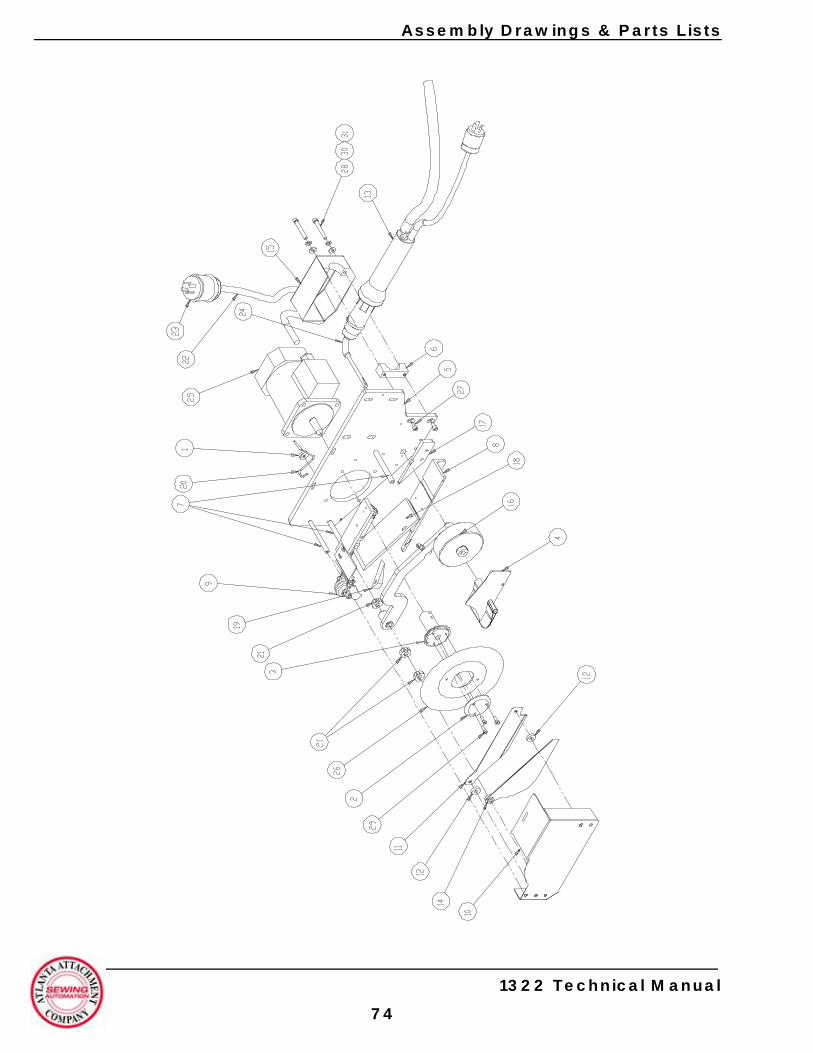
Assembly Drawings & Parts Lists
1322 Technical Manual
74
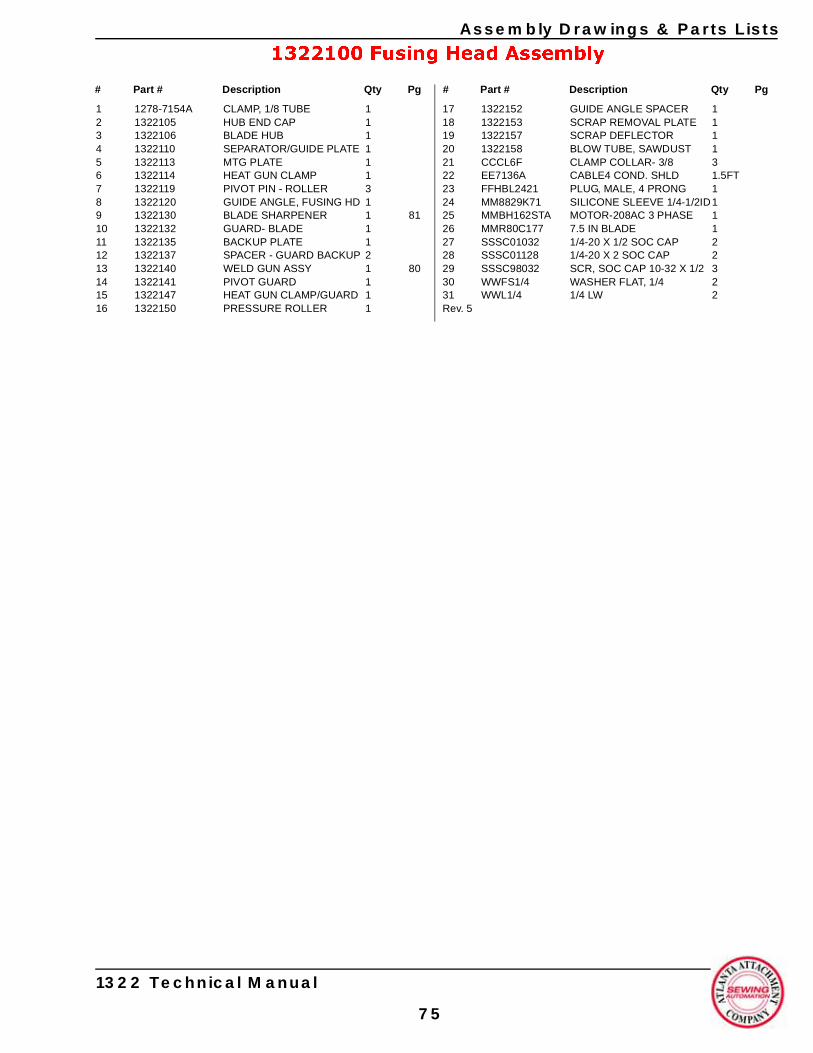
Assembly Drawings & Parts Lists
1322100 Fusing Head Assembly
1 1278-7154A CLAMP, 1/8 TUBE 12 1322105 HUB END CAP 13 1322106 BLADE HUB 14 1322110 SEPARATOR/GUIDE PLATE 15 1322113 MTG PLATE 16 1322114 HEAT GUN CLAMP 17 1322119 PIVOT PIN - ROLLER 38 1322120 GUIDE ANGLE, FUSING HD 19 1322130 BLADE SHARPENER 1 8110 1322132 GUARD- BLADE 111 1322135 BACKUP PLATE 112 1322137 SPACER - GUARD BACKUP 213 1322140 WELD GUN ASSY 1 8014 1322141 PIVOT GUARD 115 1322147 HEAT GUN CLAMP/GUARD 116 1322150 PRESSURE ROLLER 1
17 1322152 GUIDE ANGLE SPACER 118 1322153 SCRAP REMOVAL PLATE 119 1322157 SCRAP DEFLECTOR 120 1322158 BLOW TUBE, SAWDUST 121 CCCL6F CLAMP COLLAR- 3/8 322 EE7136A CABLE4 COND. SHLD 1.5FT23 FFHBL2421 PLUG, MALE, 4 PRONG 124 MM8829K71 SILICONE SLEEVE 1/4-1/2ID125 MMBH162STA MOTOR-208AC 3 PHASE 126 MMR80C177 7.5 IN BLADE 127 SSSC01032 1/4-20 X 1/2 SOC CAP 228 SSSC01128 1/4-20 X 2 SOC CAP 229 SSSC98032 SCR, SOC CAP 10-32 X 1/2 330 WWFS1/4 WASHER FLAT, 1/4 231 WWL1/4 1/4 LW 2Rev. 5
# Part # Description Qty Pg # Part # Description Qty Pg
1322 Technical Manual
75
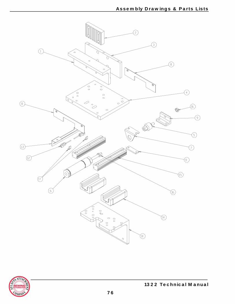
Assembly Drawings & Parts Lists
1322 Technical Manual
76

Assembly Drawings & Parts Lists
1322021 Carriage 1 Assembly
1 1322013 Belt Clamp 12 MMCPL100 Belt Clamp 13 1322015 Standoff Plate 14 1322022 Cylinder Mnt Plate 15 AAF312 Rod End 16 AAC6D-1.5 Air Cylinder 17 AAFD-129 Mnt Brkt 18 1322025 Bearing Stop Plate 29 1322029 Cylinder Rod Mnt 1
10 1322016 Head Mnt Angle 111 1322024 Nut Plate 112 1278-7055D Prox Switch 213 1322026 Sensor Mnt Brkt 114 MMAGH25CA Linear Bearing 215 MMAGR25139 Linear Rail 216 NNJ5/16-24 Jam Nut 217 1335M-2034 Nut Plate 2Rev. 0
# Part # Description Qty Pg # Part # Description Qty Pg
1322 Technical Manual
77
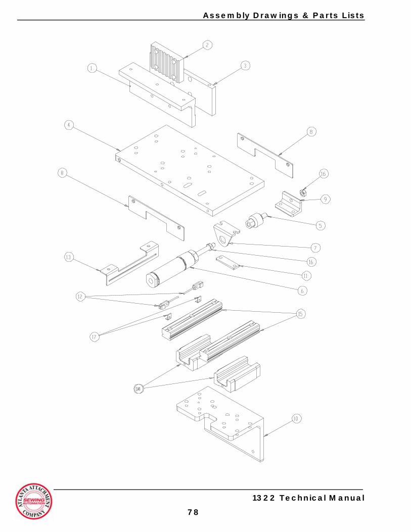
Assembly Drawings & Parts Lists
1322 Technical Manual
78

Assembly Drawings & Parts Lists
1322006 Carriage 2 Assembly
1 1322013 Belt Clamp 12 MMCPL100 Belt Clamp 13 1322015 Standoff Plate 14 1322017 Cylinder Mnt Plate 15 AAF312 Rod End 16 AAC6D-1.5 Air Cylinder 17 AAFD-129 Mnt Brkt 18 1322025 Bearing Stop Plate 29 1322029 Cylinder Rod Mnt 1
10 1322016 Head Mnt Angle 111 1322024 Nut Plate 112 1278-7055D Prox Switch 213 1322026 Sensor Mnt Brkt 114 MMAGH25CA Linear Bearing 215 MMAGR25139 Linear Rail 216 NNJ5/16-24 Jam Nut 217 1335M-2034 Nut Plate 2Rev. 0
# Part # Description Qty Pg # Part # Description Qty Pg
1322 Technical Manual
79
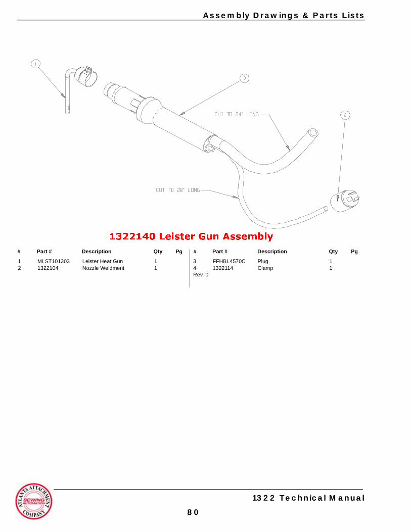
Assembly Drawings & Parts Lists
1322140 Leister Gun Assembly
1 MLST101303 Leister Heat Gun 12 1322104 Nozzle Weldment 1
3 FFHBL4570C Plug 14 1322114 Clamp 1Rev. 0
# Part # Description Qty Pg # Part # Description Qty Pg
1322 Technical Manual
80
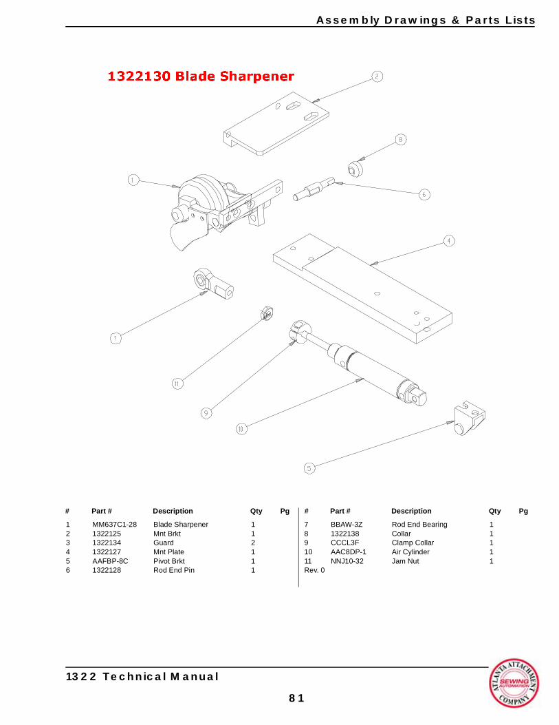
Assembly Drawings & Parts Lists
1322130 Blade Sharpener
1 MM637C1-28 Blade Sharpener 12 1322125 Mnt Brkt 13 1322134 Guard 24 1322127 Mnt Plate 15 AAFBP-8C Pivot Brkt 16 1322128 Rod End Pin 1
7 BBAW-3Z Rod End Bearing 18 1322138 Collar 19 CCCL3F Clamp Collar 110 AAC8DP-1 Air Cylinder 111 NNJ10-32 Jam Nut 1Rev. 0
# Part # Description Qty Pg # Part # Description Qty Pg
1322 Technical Manual
81
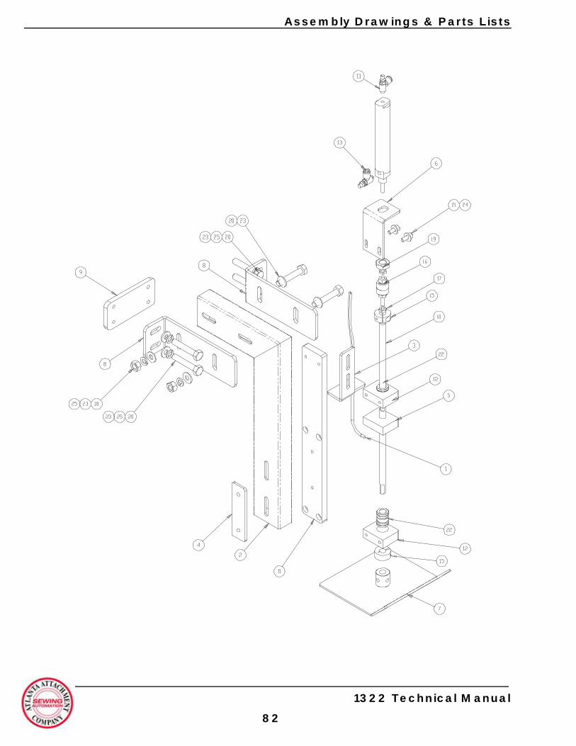
1322 Technical Manual
Assembly Drawings & Parts Lists
82
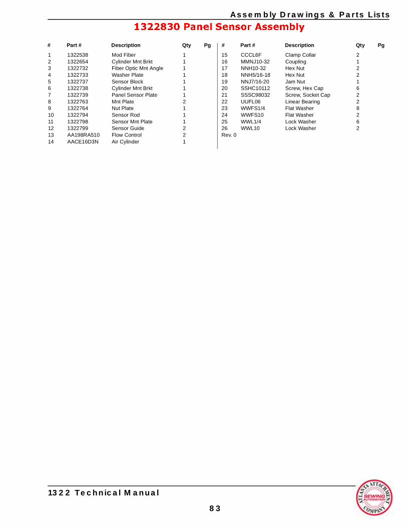
Assembly Drawings & Parts Lists
1322 Technical Manual
83
1322830 Panel Sensor Assembly
1 1322538 Mod Fiber 12 1322654 Cylinder Mnt Brkt 13 1322732 Fiber Optic Mnt Angle 14 1322733 Washer Plate 15 1322737 Sensor Block 16 1322738 Cylinder Mnt Brkt 17 1322739 Panel Sensor Plate 18 1322763 Mnt Plate 29 1322764 Nut Plate 110 1322794 Sensor Rod 111 1322798 Sensor Mnt Plate 112 1322799 Sensor Guide 213 AA198RA510 Flow Control 214 AACE16D3N Air Cylinder 1
15 CCCL6F Clamp Collar 216 MMNJ10-32 Coupling 117 NNH10-32 Hex Nut 218 NNH5/16-18 Hex Nut 219 NNJ7/16-20 Jam Nut 120 SSHC10112 Screw, Hex Cap 621 SSSC98032 Screw, Socket Cap 222 UUFL06 Linear Bearing 223 WWFS1/4 Flat Washer 824 WWFS10 Flat Washer 225 WWL1/4 Lock Washer 626 WWL10 Lock Washer 2Rev. 0
# Part # Description Qty Pg # Part # Description Qty Pg
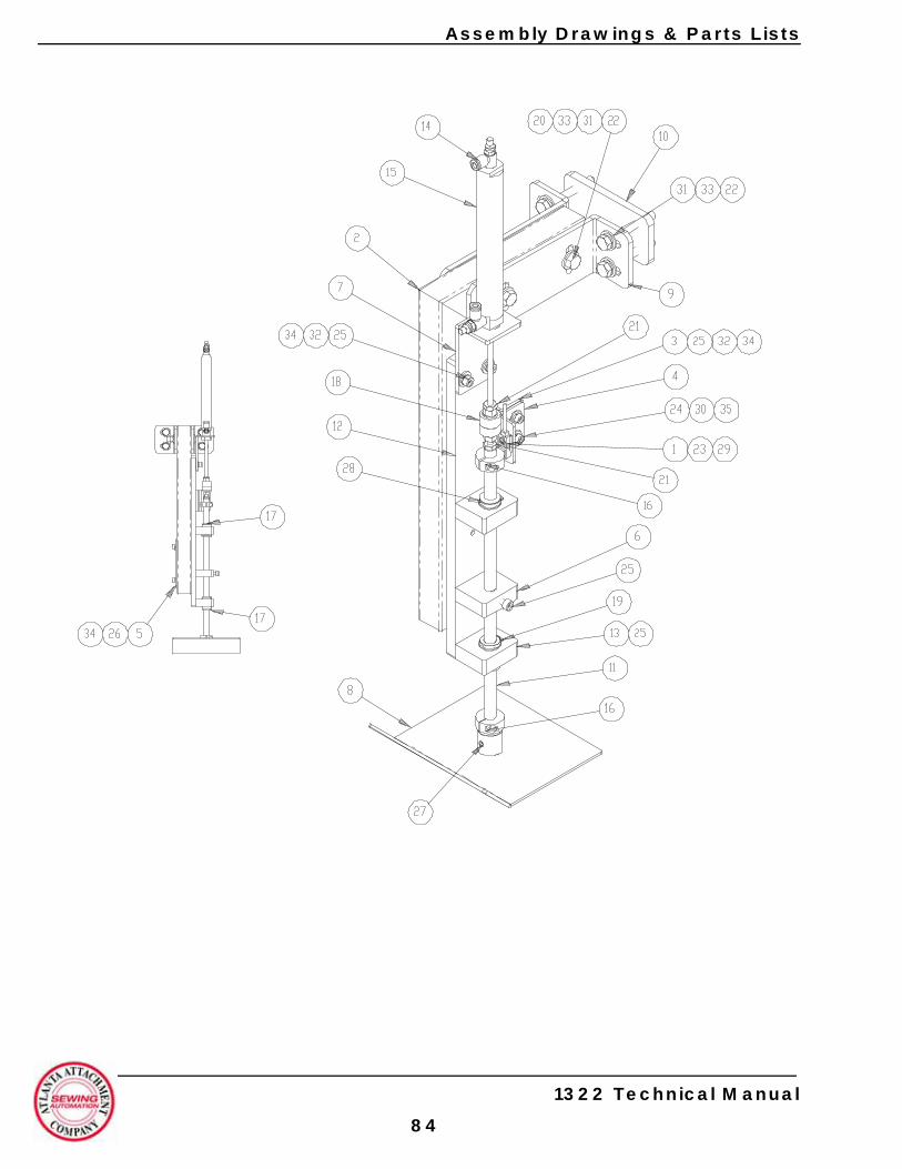
1322 Technical Manual
Assembly Drawings & Parts Lists
84
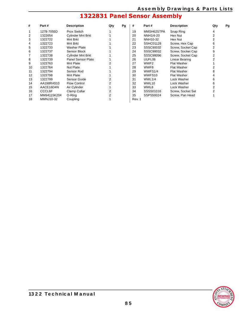
Assembly Drawings & Parts Lists
1322 Technical Manual
85
1322831 Panel Sensor Assembly
1 1278-7055D Prox Switch 12 1322654 Cylinder Mnt Brkt 13 1322722 Mnt Brkt 14 1322723 Mnt Brkt 15 1322733 Washer Plate 16 1322737 Sensor Block 17 1322738 Cylinder Mnt Brkt 18 1322739 Panel Sensor Plate 19 1322763 Mnt Plate 210 1322764 Nut Plate 111 1322794 Sensor Rod 112 1322798 Mnt Plate 113 1322799 Sensor Guide 214 AA198RA510 Flow Control 215 AACE16D4N Air Cylinder 116 CCCL6F Clamp Collar 217 MM94115K204 O-Ring 218 MMNJ10-32 Coupling 1
19 MMSH62STPA Snap Ring 420 NNH1/4-20 Hex Nut 221 NNH10-32 Hex Nut 222 SSHC01128 Screw, Hex Cap 623 SSSC90032 Screw, Socket Cap 224 SSSC98032 Screw, Socket Cap 925 SSSC98096 Screw, Socket Cap 226 UUFL06 Linear Bearing 227 WWF2 Flat Washer 128 WWF8 Flat Washer 229 WWFS1/4 Flat Washer 830 WWFS10 Flat Washer 431 WWL1/4 Lock Washer 632 WWL10 Lock Washer 633 WWL8 Lock Washer 234 SSSS01016 Screw, Socket Set 235 SSPS50024 Screw, Pan Head 1Rev. 1
# Part # Description Qty Pg # Part # Description Qty Pg

Assembly Drawings & Parts Lists
1322 Technical Manual
86
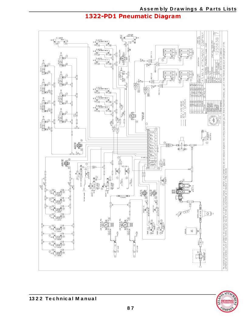
Assembly Drawings & Parts Lists
1322-PD1 Pneumatic Diagram
1322 Technical Manual
87
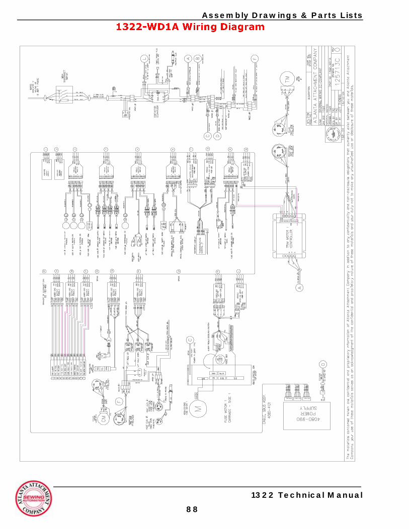
Assembly Drawings & Parts Lists
1322-WD1A Wiring Diagram
1322 Technical Manual
88
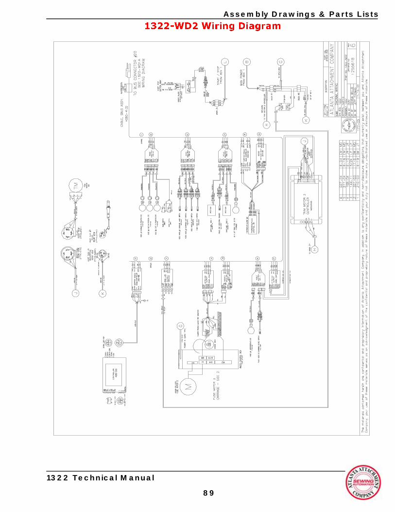
Assembly Drawings & Parts Lists
1322-WD2 Wiring Diagram
1322 Technical Manual
89

Assembly Drawings & Parts Lists
1322 Technical Manual
90

Atlanta Attachment Company (AAC)Statement of Warranty
Manufactured ProductsAtlanta Attachment Company warrants manufactured products to be free from defects in material and workmanship for a period of eight hundred (800) hours of operation or one hundred (100) days which ever comes first. Atlanta Attachment Company warrants all electrical components of the Serial Bus System to be free from defects in material or workmanship for a period of thirty six (36) months.
Terms and Conditions:• AAC Limited Warranty becomes effective on the date of shipment.• AAC Warranty claims may be made by telephone, letter, fax or e-mail. All verbal claims must be con-
firmed in writing. • AAC reserves the right to require the return of all claimed defective parts with a completed warranty
claim form.• AAC will, at its option, repair or replace the defective machine and parts upon return to AAC. • AAC reserves the right to make the final decision on all warranty coverage questions. • AAC warranty periods as stated are for eight hundred (800) hours or one hundred (100) days which
ever comes first. • AAC guarantees satisfactory operation of the machines on the basis of generally accepted industry
standards, contingent upon proper application, installation and maintenance.• AAC Limited Warranty may not be changed or modified and is not subject to any other warranty
expressed or implied by any other agent, dealer, or distributor unless approved in writing by AAC in advance of any claim being filed.
What Is Covered• Electrical components that are not included within the Serial Bus System that fail due to defects in
material or workmanship, which are manufactured by AAC are covered for a period of eight hundred (800) hours.
• Mechanical parts or components that fail due to defects in material or workmanship, which are manu-factured by AAC.
• Purchased items (sewing heads, motors, etc.) will be covered by the manufacturer's (OEM) warranty. • AAC will assist in the procurement and handling of the manufacturer's (OEM) claim.
What Is Not Covered• Parts that fail due to improper usage, lack of proper maintenance, lubrication and/or modification.• Damages caused by; improper freight handling, accidents, fire and issues resulting from unauthorized
service and/or personnel, improper electrical, plumbing connections.• Normal wear of machine and parts such as Conveyor belts, "O" rings, gauge parts, cutters, needles, etc.• Machine adjustments related to sewing applications and/or general machine operation.• Charges for field service. • Loss of time, potential revenue, and/or profits.• Personal injury and/or property damage resulting from the operation of this equipment.

Atlanta Attachment Company (AAC)Declaración de Garantia
Productos ManufacturadosAtlanta Attachment Company garantiza que los productos de fabricación son libre de defectos de material y de mano de obra durante un periodo de ochociento (800) horas de operación or cien (100) dias cual llega primero. Atlanta Attachment Company garantiza que todos los componentes del bus serie son libre de defectos de material y de mano de obra durante un periodo de treinta y seis (36) meses.
Términos y Condiciones:• La Garantia Limitada de AAC entra en efecto el dia de transporte. • Reclamos de la Garantia deAAC pueden ser realizados por telefono, carta, fax o correo electrónico.
Todo reclamo verbal tiene que ser confirmado via escrito.• AAC reserva el derecho para exigir el retorno de cada pieza defectousa con un formulario de reclamo
de garantia.• AAC va, según su criterio, reparar o reemplazar la máquina o pieza defectuoso devuelto para AAC. • AAC reserva el derecho para tomar la decisión final sobre toda question de garantia.• Las garantias de AAC tiene un validez de ococientas (800) horas o cien (100) dias cual llega primerlo. • AAC garantiza operación satisfactoria de sus máquinas en base de las normas aceptadas de la industria
contigente en la instalación y mantenimiento adecuada.• La garantia de AAC no puede ser cambiado o modificado y no está sujeto a cualquier otra garantia
implicado por otro agente o distribuidor menos que sea autorizado por AAC antes de cualquier rec-lamo.
Lo Que Está Garantizado• Componentes eléctricos que no está incluidos dentro del sistema Bus Serie que han sido manufactura-
dos por AAC son garantizados por un periodo de ochocientas (800) horas.• Mechanical parts or components that fail due to defects in material or workmanship, which are manu-
factured by AAC. • Componentes comprados (Motores, Cabezales, ) son protegidos debajo de la garantia del fabricante.• AAC asistirá con el manejo de todo reclamo de garantia bajo la garantia del fabricante.
Lo Que No Está Garantizado• Falla de repuestos al raiz de uso incorrecto, falta de mantenimiento, lubricación o modificación.• Daños ocuridos al raiz de mal transporte, accidentes, incendio o cualquier daño al resultado de servicio
por personas no autorizados o instalaciones incorrectas de conecciones eléctricas o neumáticas. • Desgaste normal de repuestos como correas, anillos de goma, cuchillos, agujas, etc. • Ajustes de la máquina en relación a las aplicaciones de costura y/o la operación en general de la
máquina.• Gastos de reparaciones en el campo. • Pérdida de tiempo, ingresos potenciales, y/o ganancias. • Daños personales y/o daños al propiedad al resultado de la operacion de este equipo.


© 2003-2005 Atlanta Attachment Company. All rights reserved.
© 2003-2005 Atlanta Attachment Company. Derechos reservados.