Embed Size (px)
Citation preview

U.S. ARMYSUBMISSION OF PROPOSALS
Topics
The Army participates in one solicitation each year with a coordinated Phase I and Phase II proposal evaluation and selection process. The Army has identified 169 technical topics for this solicitation which will address the Technology Areas in the Defense Technology Plan and the Army Science and Technology Master Plan. The Phase III dual-use applications for each of these topics have also been identified.
Operation and Support Cost Reduction (OSCR)
The U. S. Army spends a large part of its overall budget, directly or indirectly, on the operation and support (O&S) of equipment ranging from small generators to large, sophisticated weapon systems. O&S costs cover a broad spectrum of items including spare/repair parts, fuels, lubricants, and the facilities and people involved in training operators and mechanics. The Army is seeking ways to reduce these costs as a broad Acquisition Reform initiative. To this end, the Army has implemented the Operation and Support Cost Reduction (OSCR) Program. This solicitation includes 61 topics that address specific OSCR concerns identified by the Army s research and development community.
Technology Areas
Each Army SBIR topic is tied to one of the 19 technology areas, listed below, which are described in the Army Science and Technology Master Plan.
1 Aerospace Propulsion and Power2 Air and Space Vehicles3 Chemical and Biological Defense (CBD) and Nuclear4 Individual Survivability and Sustainability5 Command, Control, and Communications6 Computing and Software7 Conventional Weapons8 Electron Devices9 Electronic Warfare/Directed Energy Weapons10 Civil Engineering and Environmental Quality11 Battlespace Environments12 Human-Systems Interface (HSI)13 Manpower, Personnel, and Training14 Materials, Processes, and Structures15 Medical and Biomedical Science and Technology16 Sensors17 Ground Vehicles18 Manufacturing Science and Technology19 Modeling and Simulation (M&S)
Phase I Proposal Guidelines
The Army has enhanced its Phase I-Phase II transition process by implementing the use of a Phase I Option that the Army may exercise to fund interim Phase II activities while a Phase II contract is being negotiated. The maximum dollar amount for a Phase I feasibility study is $70,000. The Phase I Option, which must be proposed as part of the Phase I proposal, covers activities over a period of up to four months and at a cost not to exceed $50,000. All proposed Phase I Options must be fully costed and should describe appropriate initial Phase II activities which would lead, in the event of a Phase II award, to the successful demonstration of a product or technology. The Army will not accept Phase I proposals which exceed $70,000 for the Phase I effort and $50,000 for the Phase I Option effort. Only those Phase I efforts selected for Phase II awards through the
Army 1

Armys competitive process will be eligible for exercise of the Phase I Option. To maintain the total cost for SBIR Phase I and Phase II activities at a limit of $850,000, the total funding amount available for Phase II activities under a resulting Phase II contract will be $730,000.
Companies submitting a Phase I proposal under this Solicitation must complete the Cost Proposal, Appendix C, within a total cost of $70,000 (plus up to $50,000 for the Phase I Option). Phase I and Phase I Option costs must be shown separately; however, they may be presented side-by-side on a single Appendix C. The Phase I Option proposal must be included within the 25-page limit for the Phase I proposal. In addition, all offerors will prepare an Appendix E, Company Commercialization Report, for each proposal submitted. Appendix E does not count toward the 25-page limitation.
Selection of Phase I proposals will be based upon scientific and technical merit, according to the evaluation procedures and criteria discussed in this solicitation document. Due to limited funding, the Army reserves the right to limit awards under any topic, and only those proposals of superior scientific and technical quality will be funded.
Proposals not conforming to the terms of this solicitation and unsolicited proposals will not be considered. Awards will be contingent on availability of funding and successful completion of contract negotiations.
Phase II Proposal GuidelinesPhase II Proposal Guidelines
Phase II proposals are invited by the Army from Phase I projects that have demonstrated the potential for commercialization of useful products and services. The invitation will be issued by the Army organization responsible for the Phase I effort. Invited proposers are required to develop and submit a commercialization plan describing feasible approaches for marketing the developed technology. Fast Track participants may submit a proposal without being invited. Cost-sharing arrangements in support of Phase II projects and any future commercialization efforts are strongly encouraged, as are matching funds from independent third-party investors, per the SBIR Fast Track program (see section 4.5). Commercialization plans, cost-sharing provisions, and matching funds from investors will be considered in the evaluation and selection process, and Fast Track proposals will be evaluated under the Fast Track standard discussed in section 4.3. Phase II proposers are required to submit a budget for a base year (first 12 months) and an option year. These costs must be submitted using Appendix C, Cost Proposal, and may be presented side-by-side on a single Cost Proposal Sheet. The total proposed amount should be indicated on Appendix A, Proposed Cost. Phase II projects will be evaluated after the base year prior to extending funding for the option year.
The Army is committed to minimizing the funding gap between Phase I and Phase II activities. With the implementation of Phase I Options effective with this 98.2 Solicitation, all Army Phase II proposals will receive expedited reviews and be eligible for interim funding. Accordingly, all Army Phase II proposals, including Fast Track submissions, will be evaluated within a single evaluation schedule.
Submission of Army SBIR Proposals
All proposals written in response to topics in this solicitation must be received by the date and time indicated in Section 6.2 of the introduction to the DoD solicitation. Be sure that you clearly identify the specific Army topic that your proposal addresses. All Phase I proposals (one original, with original signatures, and four copies) must be submitted to the Army SBIR Program Management Office at the address below. All hand deliveries must be made to the mail room, located at the rear of the building.
Dr. Kenneth A. BannisterU.S. Army Research Office-Washington5001 Eisenhower Avenue, Room 8N31Alexandria, VA 22333-0001(703) 617-7425
The Organizations issuing the Phase II proposal invitations will provide Phase II instructions at the time of Phase I awards.
Army 2

Key Dates
98.2 Solicitation Open 1 July - 19 August 1998Phase I Evaluations August - November 1998Phase I Selections November 1998Phase I Awards December 1998
Recommendation of Future Topics
Small Businesses are encouraged to suggest ideas that may be included in future Army SBIR solicitations. These suggestions should be directed to the SBIR points-of-contact at the respective Army research and development organizations.
Inquiries
Inquiries of a general nature should be addressed to:
Dr. Kenneth A. Bannister LTC Warren GreeneArmy SBIR Program Manager Army SBIR Program CoordinatorU.S. Army Research Office - Washington Headquarters, Department of the ArmyRoom 8N31 Office of the Assistant Secretary of the Army5001 Eisenhower Avenue (Research, Development and Acquisition)Alexandria, VA 22333-0001 2511 Jefferson Davis Highway (703) 617-7425 Arlington, VA 22202-3911
(703) 601-1502
Army 3
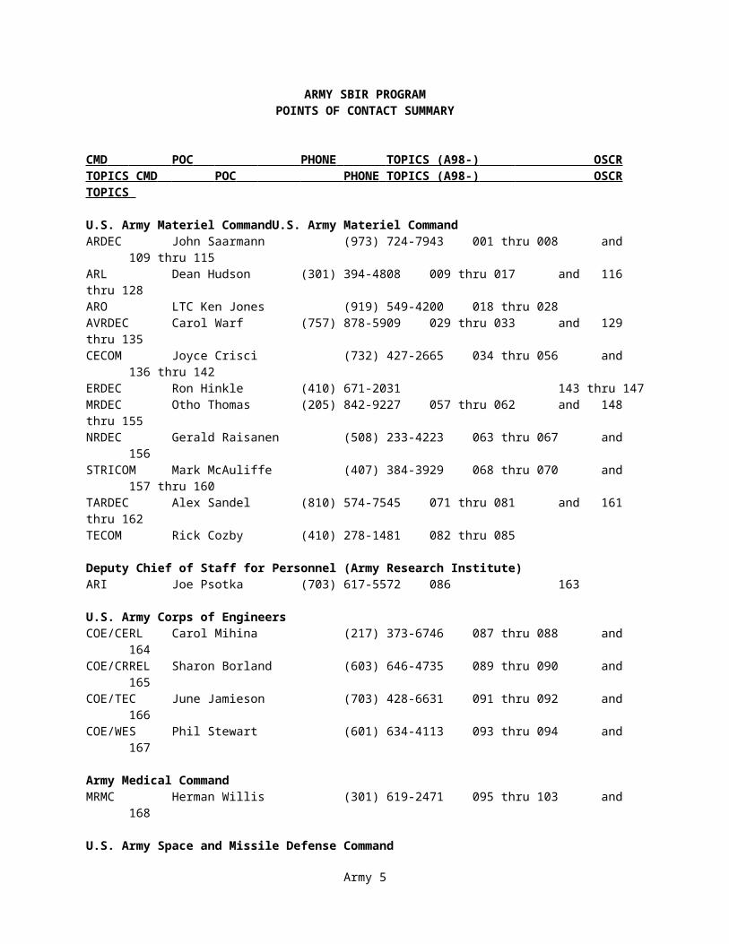
ARMY SBIR PROGRAMPOINTS OF CONTACT SUMMARY
CMD POC PHONE TOPICS (A98-) OSCR TOPICS CMD POC PHONE TOPICS (A98-) OSCR TOPICS
U.S. Army Materiel CommandU.S. Army Materiel CommandARDEC John Saarmann (973) 724-7943 001 thru 008 and 109 thru 115ARL Dean Hudson (301) 394-4808 009 thru 017 and 116 thru 128ARO LTC Ken Jones (919) 549-4200 018 thru 028AVRDEC Carol Warf (757) 878-5909 029 thru 033 and 129 thru 135CECOM Joyce Crisci (732) 427-2665 034 thru 056 and 136 thru 142ERDEC Ron Hinkle (410) 671-2031 143 thru 147MRDEC Otho Thomas (205) 842-9227 057 thru 062 and 148 thru 155NRDEC Gerald Raisanen (508) 233-4223 063 thru 067 and 156STRICOM Mark McAuliffe (407) 384-3929 068 thru 070 and 157 thru 160TARDEC Alex Sandel (810) 574-7545 071 thru 081 and 161 thru 162TECOM Rick Cozby (410) 278-1481 082 thru 085
Deputy Chief of Staff for Personnel (Army Research Institute)ARI Joe Psotka (703) 617-5572 086 163
U.S. Army Corps of EngineersCOE/CERL Carol Mihina (217) 373-6746 087 thru 088 and 164COE/CRREL Sharon Borland (603) 646-4735 089 thru 090 and 165COE/TEC June Jamieson (703) 428-6631 091 thru 092 and 166COE/WES Phil Stewart (601) 634-4113 093 thru 094 and 167
Army Medical CommandMRMC Herman Willis (301) 619-2471 095 thru 103 and 168
U.S. Army Space and Missile Defense CommandSMDC Terry Bauer (205) 955-5456 104 thru 108 and 169
Army 4
DEPARTMENT OF THE ARMYPROPOSAL CHECKLIST
This is a Checklist of Requirements for your proposal. Please review the checklist carefully to assure that your proposal meets the Army SBIR requirements. Failure to meet these requirements will result in your proposal not being considered for review or award. Do not include this checklist with your proposal.
*___ 1. The proposal budget may be up to $70,000 for a six-month duration and up to $50,000 for a four-month option to provide interim Phase II funding.
_____ 2. The proposal is limited to only ONE ARMY solicitation topic.
_____ 3. The proposal plus the Phase I Option is 25 pages or less in length. (Excluding company commercialization report.) Proposals in excess of this length will not be considered for review or award.
_____ 4. The Cover Sheet (Appendix A) has been completed and is PAGE 1 of the proposal.
_____ 5. The Project Summary Sheet (Appendix B) has been completed and is PAGE 2 of the proposal.
_____ 6. The Technical Content of the proposal, including the Option, begins on PAGE 3 and includes the items identified in Section 3.4 of the solicitation.
_____ 7. The Project Summary, Appendix B, contains no proprietary information, does not exceed 200 words, and is limited to the space provided.
_____ 8. The proposal contains only pages of 8 1/2 X 11 size. No other attachments such as disks, video tapes, etc. are included.
_____ 9. The proposal contains no type smaller than 11 point font size (except as legend on reduced drawings, but not tables).
_____ 10. The Contract Pricing Proposal has been completed for the Phase I and Phase I Option costs and are shown separately (Appendix C) and is included as the last section of the proposal.
_____ 11. The final proposal is stapled in the upper-left-hand corner, and no special binding or covers are used.
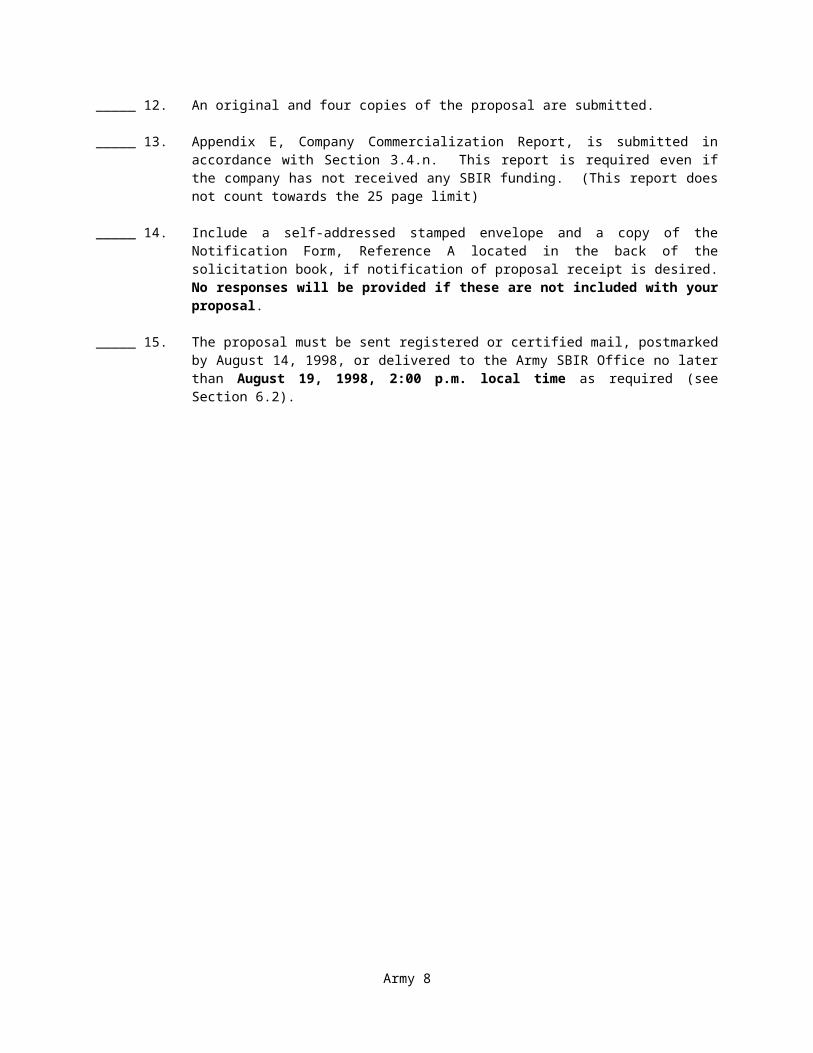
_____ 12. An original and four copies of the proposal are submitted.
_____ 13. Appendix E, Company Commercialization Report, is submitted in accordance with Section 3.4.n. This report is required even if the company has not received any SBIR funding. (This report does not count towards the 25 page limit)
_____ 14. Include a self-addressed stamped envelope and a copy of the Notification Form, Reference A located in the back of the solicitation book, if notification of proposal receipt is desired. No responses will be provided if these are not included with your proposal.
_____ 15. The proposal must be sent registered or certified mail, postmarked by August 14, 1998, or delivered to the Army SBIR Office no later than August 19, 1998, 2:00 p.m. local time as required (see Section 6.2).
Army 5

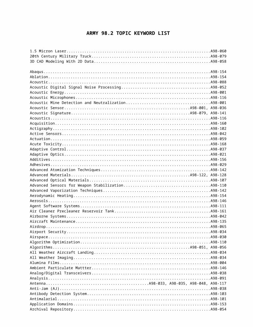
ARMY 98.2 TOPIC KEYWORD LIST
1.5 Micron Laser.............................................................................................................................................................A98-06020th Century Military Truck............................................................................................................................................A98-0793D CAD Modeling With 2D Data....................................................................................................................................A98-058
Abaqus............................................................................................................................................................................A98-154Ablation...........................................................................................................................................................................A98-154Acoustic..........................................................................................................................................................................A98-088Acoustic Digital Signal Noise Processing........................................................................................................................A98-052Acoustic Energy..............................................................................................................................................................A98-001Acoustic Microphones.....................................................................................................................................................A98-116Acoustic Mine Detection and Neutralization....................................................................................................................A98-001Acoustic Sensor................................................................................................................................................A98-001, A98-036Acoustic Signature...........................................................................................................................................A98-079, A98-141Acoustics.........................................................................................................................................................................A98-116Acquisition......................................................................................................................................................................A98-160Actigraphy....................................................................................................................................................................... A98-102Active Sensors.................................................................................................................................................................A98-042Actuation.........................................................................................................................................................................A98-059Acute Toxicity.................................................................................................................................................................A98-168Adaptive Control.............................................................................................................................................................A98-037Adaptive Optics...............................................................................................................................................................A98-021Additives.........................................................................................................................................................................A98-156Adhesives........................................................................................................................................................................A98-029Advanced Atomization Techniques..................................................................................................................................A98-142Advanced Materials..........................................................................................................................................A98-122, A98-128Advanced Optical Materials.............................................................................................................................................A98-107Advanced Sensors for Weapon Stabilization....................................................................................................................A98-110Advanced Vaporization Techniques.................................................................................................................................A98-142Aerodynamic Heating......................................................................................................................................................A98-154Aerosols..........................................................................................................................................................................A98-146Agent Software Systems..................................................................................................................................................A98-111Air Cleaner Precleaner Reservoir Tank............................................................................................................................A98-161Airborne Systems............................................................................................................................................................A98-042Aircraft Maintenance.......................................................................................................................................................A98-135Airdrop............................................................................................................................................................................A98-065Airport Security...............................................................................................................................................................A98-034Airspace..........................................................................................................................................................................A98-030Algorithm Optimization...................................................................................................................................................A98-110Algorithms.......................................................................................................................................................A98-051, A98-056All Weather Aircraft Landing..........................................................................................................................................A98-034All Weather Imaging.......................................................................................................................................................A98-034Alumina Films.................................................................................................................................................................A98-004Ambient Particulate Mattter.............................................................................................................................................A98-146Analog/Digital Transceivers............................................................................................................................................A98-038Analysis...........................................................................................................................................................................A98-091Antenna.............................................................................................................................A98-033, A98-035, A98-048, A98-117Anti-Jam (AJ)..................................................................................................................................................................A98-038Antibody Detection System.............................................................................................................................................A98-103Antimalarial..................................................................................................................................................................... A98-101Application Domains.......................................................................................................................................................A98-153Archival Repository.........................................................................................................................................................A98-054Armor..............................................................................................................................................................A98-072, A98-122Armor Skirts.................................................................................................................................................................... A98-072Artificial Intelligence.......................................................................................................................................................A98-108ATM Adaptation Layer (AAL)........................................................................................................................................A98-045Atmospheric Models........................................................................................................................................................A98-144Automated Recognition...................................................................................................................................................A98-051Automatic Activation.......................................................................................................................................................A98-065Automatic Target Recognition (ATR)..............................................................................................................................A98-058Automatic Test Systems (ATS)........................................................................................................................................A98-155

Automation......................................................................................................................................................A98-111, A98-126Azacyclic......................................................................................................................................................................... A98-115
Ballistics..........................................................................................................................................................................A98-081Bandwidth Efficiency......................................................................................................................................................A98-045Batteries.......................................................................................................................................................................... A98-011Battery............................................................................................................................................................................. A98-138Battlefield........................................................................................................................................................................ A98-041BB-X590 Battery.............................................................................................................................................................A98-138Benchmarking..................................................................................................................................................................A98-054Bioaerosols......................................................................................................................................................................A98-146Bioinformatics.................................................................................................................................................................A98-101Biomimetics.................................................................................................................................................................... A98-028Biomolecular Synthesis...................................................................................................................................................A98-028Biosensor......................................................................................................................................................................... A98-143Biotechnology..................................................................................................................................................................A98-097Blade-Vortex Interaction..................................................................................................................................................A98-031Blood............................................................................................................................................................................... A98-100Blood Banking.................................................................................................................................................A98-099, A98-100Blood Pressure.................................................................................................................................................................A98-102Blood Processor...............................................................................................................................................................A98-100Body Weight.................................................................................................................................................................... A98-102Boundary Layer...............................................................................................................................................................A98-154Bridges............................................................................................................................................................................A98-071
C4I.................................................................................................................................................................................. A98-068Cameras...........................................................................................................................................................................A98-083Camouflage..................................................................................................................................................................... A98-055CCD................................................................................................................................................................................ A98-148Cellular PCS....................................................................................................................................................................A98-038Ceramic Matrix Composite..............................................................................................................................A98-072, A98-081Ceramics.......................................................................................................................................................................... A98-072Characteristic X-Rays......................................................................................................................................................A98-003Characterization...............................................................................................................................................A98-088, A98-126Charring Ablator..............................................................................................................................................................A98-154Chemical Agent Detection...............................................................................................................................................A98-144Chemical Defense............................................................................................................................................................A98-051Chemical Effluents..........................................................................................................................................................A98-051Chemical Identification....................................................................................................................................................A98-051Chemical Sensors............................................................................................................................................................A98-027Chemical/Biological Protection.......................................................................................................................................A98-067Clutter............................................................................................................................................................................. A98-106Clutter/Noise Analysis.....................................................................................................................................................A98-091CMC................................................................................................................................................................................A98-022Coatings..........................................................................................................................................................................A98-055Collaboration...................................................................................................................................................................A98-040Collaborative Product Design & Development.................................................................................................................A98-080Collection Efficiency.......................................................................................................................................................A98-146Collision Avoidance........................................................................................................................................................A98-034Combat Clothing..............................................................................................................................................................A98-156Combat Training Centers.................................................................................................................................................A98-068Combinatorial Chemistry.................................................................................................................................................A98-101Combustor........................................................................................................................................................A98-129, A98-133Command and Control.....................................................................................................................................................A98-040Communication.................................................................................................................A98-012, A98-035, A98-048, A98-087Compact Power................................................................................................................................................A98-019, A98-023Compact Solid State Laser...............................................................................................................................................A98-147Component...................................................................................................................................................................... A98-153Composite.........................................................................................................................A98-029, A98-078, A98-119, A98-150Composite Looms............................................................................................................................................................A98-119Composite Materials........................................................................................................................................................A98-142Composite Structures.......................................................................................................................................................A98-150Compression Ignition Engine Technologies.....................................................................................................................A98-162Compressors.................................................................................................................................................................... A98-133
Computations Fluid Dynamics.........................................................................................................................................A98-152Computer Algorithm........................................................................................................................................................A98-035Computer Generated Forces.............................................................................................................................A98-157, A98-159Computer Graphics..........................................................................................................................................................A98-035Computer-Aided Maintenance.........................................................................................................................................A98-131Computing....................................................................................................................................................................... A98-136Computing and Software..................................................................................................................................................A98-079Conductive......................................................................................................................................................................A98-067Constructive Models........................................................................................................................................................A98-163Container Handling Equipment........................................................................................................................................A98-114Contour Map.................................................................................................................................................................... A98-046Control Fins..................................................................................................................................................................... A98-154Control System................................................................................................................................................................A98-059Controls........................................................................................................................................................................... A98-133Cooling............................................................................................................................................................................ A98-017CORBA...........................................................................................................................................................................A98-080Correction........................................................................................................................................................................A98-169Correlation.......................................................................................................................................................A98-137, A98-159Corrosion Resistant Coatings...........................................................................................................................................A98-004Cosite Interference...........................................................................................................................................................A98-047Cosite Interference Counter Measure...............................................................................................................................A98-050Countermine.................................................................................................................................................................... A98-118Covert Radar Imaging......................................................................................................................................................A98-034Crossbar Switch...............................................................................................................................................................A98-117Cryroelectrochemistry.....................................................................................................................................................A98-018Curing of Composites......................................................................................................................................................A98-078
Data Correlation..............................................................................................................................................................A98-031Data Fusion......................................................................................................................................................A98-005, A98-108Data Translation..............................................................................................................................................................A98-054Database Security............................................................................................................................................................A98-054Decision Aid.................................................................................................................................................................... A98-108Deconfliction...................................................................................................................................................................A98-030Decontamination..............................................................................................................................................................A98-084Deep Tissue Blood Flow..................................................................................................................................................A98-096Defects In Composites.....................................................................................................................................................A98-078Dental.............................................................................................................................................................................. A98-095Dental Equipment............................................................................................................................................................A98-095Dental Handpiece.............................................................................................................................................................A98-095Deposition of Crystalline Alumina Films.........................................................................................................................A98-004Desktop Manufacturing....................................................................................................................................................A98-025Detection..........................................................................................................................................................A98-084, A98-088DI SAF............................................................................................................................................................................A98-157Diagnosis......................................................................................................................................................................... A98-096Diagnostic Equipment......................................................................................................................................................A98-150Diagnostic Tests..............................................................................................................................................................A98-099Diesel Engine Advanced Technologies............................................................................................................................A98-162Diesel Engine Re-Manufacture........................................................................................................................................A98-162Diesel Engines.................................................................................................................................................................A98-013Digital............................................................................................................................................................................. A98-136Digital Compression........................................................................................................................................................A98-045Digital Micromirror Device.............................................................................................................................................A98-057Digital Prototyping..........................................................................................................................................................A98-080Digitized Battlefield........................................................................................................................................................A98-037Directed Energy...............................................................................................................................................................A98-139Direction Finding.............................................................................................................................................................A98-039Displacement...................................................................................................................................................................A98-044Distance Learning............................................................................................................................................................A98-069Distributed Object Processing..........................................................................................................................................A98-008Distributed Optimization.................................................................................................................................................A98-008Distributed Processing.....................................................................................................................................................A98-080DNA................................................................................................................................................................................A98-098DNA Oligonucleotide Microarrays..................................................................................................................................A98-097DNA/Gene Chip Technology...........................................................................................................................................A98-097
Domain Modeling............................................................................................................................................................A98-112Drive Systems..................................................................................................................................................................A98-014Drug Discovery................................................................................................................................................................A98-097Dynamic and Impulse Modeling......................................................................................................................................A98-079Dynamic Pressure............................................................................................................................................................A98-154Dynamic Terrain..............................................................................................................................................................A98-158
Earthmoving.................................................................................................................................................................... A98-071Ehrlichial......................................................................................................................................................................... A98-103Electric Motor.................................................................................................................................................................A98-095Electric Power................................................................................................................................................................. A98-140Electrochemical Capacitors..............................................................................................................................................A98-011Electrochemically Deposited Materials............................................................................................................................A98-018Electrode......................................................................................................................................................................... A98-138Electrodeposited Materials...............................................................................................................................................A98-018Electrolyte.......................................................................................................................................................................A98-011Electromagnetic Spectrum...............................................................................................................................................A98-049Electronics....................................................................................................................................................................... A98-136Electronic Scanning.........................................................................................................................................................A98-117Electronic Warfare...........................................................................................................................................................A98-139Electrospinning................................................................................................................................................................A98-024Electrostatic..................................................................................................................................................................... A98-067Electrosynthesis...............................................................................................................................................................A98-018Embedded Sensors...........................................................................................................................................................A98-109Embedded Training..........................................................................................................................................................A98-157Encapsulation...................................................................................................................................................A98-072, A98-156Energetic Materials..........................................................................................................................................................A98-115Energy............................................................................................................................................................................. A98-085Energy Storage.................................................................................................................................................A98-011, A98-140Engine Components.........................................................................................................................................................A98-013Engine Life...................................................................................................................................................................... A98-142Engines............................................................................................................................................................................ A98-032Enhanced Oil Filter..........................................................................................................................................................A98-161Environment.................................................................................................................................................................... A98-084Environmental Microsensors............................................................................................................................................A98-109Environmentally Friendly................................................................................................................................................A98-004EPA & CARB Emission Requirements............................................................................................................................A98-142Epidemic Typhus.............................................................................................................................................................A98-103Error................................................................................................................................................................................A98-169Exoskeleton.....................................................................................................................................................................A98-016Expenditure..................................................................................................................................................................... A98-102Expert System..................................................................................................................................................................A98-092Exploitation..................................................................................................................................................................... A98-091Extremity Enhancer.........................................................................................................................................................A98-016Eyesafe Laser..................................................................................................................................................................A98-060
Fabric Strain Measurement..............................................................................................................................................A98-063Fabrics.............................................................................................................................................................A98-066, A98-156Fatigue............................................................................................................................................................................. A98-029Federated Object Model...................................................................................................................................................A98-069Fenders............................................................................................................................................................................A98-081Fiber-Optic.......................................................................................................................................................A98-063, A98-078Fibers..............................................................................................................................................................................A98-156Field Instrumented Ranges...............................................................................................................................................A98-068Filter................................................................................................................................................................A98-047, A98-067Finite Elements................................................................................................................................................................A98-154Finite-Rate Chemistry......................................................................................................................................................A98-152Fire Control Sensors........................................................................................................................................................A98-110FLIR Technology.............................................................................................................................................................A98-120Flow Controller...............................................................................................................................................................A98-023Fluorometry..................................................................................................................................................................... A98-098Focal Plane Array............................................................................................................................................................A98-009Foilage............................................................................................................................................................................. A98-055Foilage Penetration..........................................................................................................................................................A98-034
Forming Ceramics...........................................................................................................................................................A98-022Forming Composites........................................................................................................................................................A98-022Forming Metals...............................................................................................................................................................A98-022Formulization.................................................................................................................................................................. A98-153Fourier Transform Infrared (FTIR)..................................................................................................................................A98-051Framework......................................................................................................................................................................A98-153Frequency........................................................................................................................................................................A98-047Frequency Doubling Techniques......................................................................................................................................A98-107Frequency Hopping Radio Networks................................................................................................................................A98-010Frequency Modulated-Continuous Wave Radar...............................................................................................................A98-113Friend or Foe...................................................................................................................................................................A98-125Frozen Platelets...............................................................................................................................................................A98-100Fuel Filter Restriction Gauge...........................................................................................................................................A98-161Fuel Injector.................................................................................................................................................................... A98-025Functional Polymers........................................................................................................................................................A98-024
Gas Metal Arc Welding...................................................................................................................................................A98-006Gas Turbine Engines........................................................................................................................................A98-013, A98-133Gearing Improvements.....................................................................................................................................................A98-014Gears................................................................................................................................................................A98-129, A98-133GEL Bipropellant Rocket Engine.....................................................................................................................................A98-151Gelled Propellants............................................................................................................................................................A98-151Generic Instrument Class (GIC).......................................................................................................................................A98-155Genome............................................................................................................................................................A98-097, A98-101Geospatial Data Management..........................................................................................................................................A98-166Global Position System (GPS)..........................................................................................................A98-026, A98-033, A98-044Gray Water...................................................................................................................................................................... A98-064Ground Sensor Systems...................................................................................................................................................A98-042Gun Propellants...............................................................................................................................................................A98-002
Hand-Held Terminals.......................................................................................................................................................A98-041Hardware-In-The-Loop....................................................................................................................................................A98-149Harsh Operating Environments........................................................................................................................................A98-062Hazardous Waste.............................................................................................................................................................A98-084Head Pressure Sensor.......................................................................................................................................................A98-124Head Tracker...................................................................................................................................................................A98-132Headform Design.............................................................................................................................................................A98-124Health Monitoring...........................................................................................................................................................A98-150Heat Exchanges...............................................................................................................................................................A98-013Heat Treatment................................................................................................................................................................A98-133Heavy-Fuel...................................................................................................................................................................... A98-032Helicopter Flying Qualities..............................................................................................................................................A98-130Helicopter Maintenance...................................................................................................................................................A98-131Helicopters...................................................................................................................................................................... A98-133Helmet Mounted Display (HMD)......................................................................................................A98-043, A98-132, A98-134High Aspect Ratio Etching...............................................................................................................................................A98-019High Brightness...............................................................................................................................................................A98-043High Efficiency...............................................................................................................................................................A98-147High Energy Laser Optics................................................................................................................................................A98-107High Level Architecture (HLA)........................................................................................................................A98-069, A98-070High Power...................................................................................................................................................................... A98-047High Power Antenna........................................................................................................................................................A98-139High Power Density Diesel..............................................................................................................................................A98-075High Speed Networking...................................................................................................................................................A98-045High Strain-Rate..............................................................................................................................................................A98-022High Temperature Packaging...........................................................................................................................................A98-074High Temperature Tribology............................................................................................................................................A98-075High Yield X-Ray Source................................................................................................................................................A98-003Highly Efficient Rocket Engine.......................................................................................................................................A98-151HMMWV Air Filter System............................................................................................................................................A98-161HMMWV Fuel Filter System...........................................................................................................................................A98-161HMMWV Oil Filter System.............................................................................................................................................A98-161Home Health Monitoring.................................................................................................................................................A98-102Human Ehrlichioses.........................................................................................................................................................A98-103
Human Performance........................................................................................................................................................A98-163Human Systems...............................................................................................................................................................A98-124Hybrid Electric Drive.......................................................................................................................................................A98-074Hybrid Systems...............................................................................................................................................................A98-008Hydration......................................................................................................................................................................... A98-102Hypersonic......................................................................................................................................................................A98-154Hyperspectral...................................................................................................................................................A98-055, A98-091Hyperspectral X-Ray Detector.........................................................................................................................................A98-007
Image Processing.............................................................................................................................................A98-015, A98-148Image Recognition and Processing...................................................................................................................................A98-021Imaging............................................................................................................................................................A98-083, A98-088Improve Durability..........................................................................................................................................................A98-142Improved Dynamic Range...............................................................................................................................................A98-043Improved Image Quality..................................................................................................................................................A98-043Improved Structural Components.....................................................................................................................................A98-122In-Situ Fouling Meter......................................................................................................................................................A98-076Increased Data Throughput..............................................................................................................................................A98-037Increased Gray Scale.......................................................................................................................................................A98-043Individual Combatant......................................................................................................................................................A98-070Inductors.......................................................................................................................................................................... A98-050Inertial............................................................................................................................................................................. A98-044Infared.............................................................................................................................................................................A98-017Infectious Disease............................................................................................................................................................A98-097Information Dominance...................................................................................................................................................A98-166Information Integration....................................................................................................................................................A98-166Infrared............................................................................................................................................................................A98-073Infrared Detectors............................................................................................................................................................A98-017Infrared Image.................................................................................................................................................................A98-120Infrared Image Projection................................................................................................................................................A98-149Infrared Missile Detector.................................................................................................................................................A98-144Infrared Optical Components...........................................................................................................................................A98-120Infrared Photodetector.....................................................................................................................................................A98-009Infrared Sensors...............................................................................................................................................................A98-036INS..................................................................................................................................................................................A98-044Insensitive Explosives......................................................................................................................................................A98-115Insertion Loss..................................................................................................................................................................A98-047Insulated Piston/Cylinder/Head........................................................................................................................................A98-075Insulation.........................................................................................................................................................................A98-066Integrated Circuit.............................................................................................................................................................A98-009Integrated Optics.............................................................................................................................................................A98-123Intelligence...................................................................................................................................................................... A98-049Intelligent Acoustic Sensors.............................................................................................................................................A98-005Intelligent Systems..........................................................................................................................................................A98-008Intercooler.......................................................................................................................................................................A98-013Internet............................................................................................................................................................................ A98-105Interoperability.................................................................................................................................................A98-112, A98-159Intranet............................................................................................................................................................................ A98-054IR Spectroscopy...............................................................................................................................................................A98-051Ischemic Respiration.......................................................................................................................................................A98-096ISO Commercial Containers............................................................................................................................................A98-114Jet-Injection..................................................................................................................................................................... A98-152Job Performance..............................................................................................................................................................A98-086Joint Tactical Radio.........................................................................................................................................................A98-037Just-In-Time Manufacturing............................................................................................................................................A98-025
Knowledge Representation...............................................................................................................................................A98-163
LADAR Imagers..............................................................................................................................................................A98-121Land Mines......................................................................................................................................................................A98-118Land Warrior................................................................................................................................................................... A98-157Language......................................................................................................................................................................... A98-012Laser................................................................................................................................................................................ A98-060Laser Beam Combiner.....................................................................................................................................................A98-121
Laser Diagnostics............................................................................................................................................................A98-107Laser Radar (LADAR)......................................................................................................................A98-060, A98-121, A98-127Lasers.............................................................................................................................................................................. A98-121Legs (Lower Extremity)...................................................................................................................................................A98-016LF Antenna...................................................................................................................................................................... A98-139Light Weight Materials....................................................................................................................................................A98-081Lightweight..................................................................................................................................................................... A98-102Lightweight High Speed Engines.....................................................................................................................................A98-142Line-Of-Sight Radios.......................................................................................................................................................A98-056Lithium Battery...............................................................................................................................................................A98-138Lithium Ion Battery.........................................................................................................................................................A98-138Live Training................................................................................................................................................................... A98-068Local Multipoint Distribution Service (LMDS)................................................................................................................A98-038Location..........................................................................................................................................................................A98-137Location Awareness.........................................................................................................................................................A98-026Logistics Automation.......................................................................................................................................................A98-111Low Cost.........................................................................................................................................................................A98-147Low Cost Materials..........................................................................................................................................................A98-072Low Cost Simulation.......................................................................................................................................................A98-158Low Heat Rejection.........................................................................................................................................................A98-075Low Power.......................................................................................................................................................A98-043, A98-136Low Probability of Intercept (LPI)...................................................................................................................................A98-038Low Profile Antenna........................................................................................................................................................A98-139Low Signature.................................................................................................................................................................A98-042Low Temperature Deposition...........................................................................................................................................A98-004
Machine Translation........................................................................................................................................................A98-012Machine Vision...............................................................................................................................................................A98-114Malaria............................................................................................................................................................................ A98-097Manufacturability............................................................................................................................................................A98-043Marking........................................................................................................................................................................... A98-071Maskless Photo-Patterning...............................................................................................................................................A98-057Material Handling Equipment..........................................................................................................................................A98-114Materiel Handling............................................................................................................................................................A98-111Mechanics of Composite Materials..................................................................................................................................A98-079Membrane.......................................................................................................................................................................A98-067Membrane Fouling...........................................................................................................................................................A98-076MEMS Technology..........................................................................................................................................................A98-048Metabolic Energy............................................................................................................................................................A98-102Micro-Terrain.................................................................................................................................................................. A98-070Microelectromechanical Systems.....................................................................................................................................A98-061Microfabrication..............................................................................................................................................................A98-023Microfabrication of Ceramics..........................................................................................................................................A98-019Microwave Monolithic Integrated Circuit (MMIC)..........................................................................................................A98-113Middle Distillate Fuels....................................................................................................................................................A98-142Millimeterwave...............................................................................................................................................................A98-106Millimeterwave Switching...............................................................................................................................................A98-117Mine Detection.................................................................................................................................................A98-001, A98-034Mine Neutralization.........................................................................................................................................................A98-001Minefields....................................................................................................................................................................... A98-071Miniature Biological Sensors...........................................................................................................................................A98-102Miniature Pumps.............................................................................................................................................................A98-023Missile Airframe..............................................................................................................................................................A98-154Missile Flight Telemetry..................................................................................................................................................A98-061Mission Performance.......................................................................................................................................................A98-145Mm-Wave.......................................................................................................................................................................A98-164MMC............................................................................................................................................................................... A98-022MMIC Radar................................................................................................................................................................... A98-113Mobile.............................................................................................................................................................A98-026, A98-064Mobile Cellular Radio.....................................................................................................................................................A98-039Mobility........................................................................................................................................................................... A98-071Model Matching with Limited Data.................................................................................................................................A98-058Modeling..........................................................................................................................................................A98-133, A98-169Modeling and Simulation..................................................................................................................A98-035, A98-056, A98-160
Modify............................................................................................................................................................................. A98-142Modular........................................................................................................................................................................... A98-064Monitoring....................................................................................................................................................................... A98-071Multi-Body Dynamics.....................................................................................................................................................A98-077Multi-Channel Analyzer..................................................................................................................................................A98-007Multi-Lingual.................................................................................................................................................................. A98-012Multi-Resolution..............................................................................................................................................................A98-104Multi-Resolution Processing SAR....................................................................................................................................A98-104Multi-Source Data...........................................................................................................................................................A98-166Multiband Multimode Radio............................................................................................................................................A98-037Multiple Links.................................................................................................................................................................A98-040Multispectral....................................................................................................................................................A98-055, A98-091Munitions........................................................................................................................................................................ A98-082Mutational Analysis.........................................................................................................................................................A98-097
Nanocomposites...............................................................................................................................................................A98-128Nanofabrication...............................................................................................................................................................A98-028Nanofibers....................................................................................................................................................................... A98-024Nanomaterials..................................................................................................................................................................A98-126Nanostructured Arrays.....................................................................................................................................................A98-028Nanoturbine.....................................................................................................................................................................A98-025Navigation........................................................................................................................................................A98-044, A98-137Negative Electrodes.........................................................................................................................................................A98-138Net-Shaped Fabrics..........................................................................................................................................................A98-119Neural Network Techniques.............................................................................................................................................A98-031Night Vision....................................................................................................................................................................A98-134Night Vision Imagery......................................................................................................................................................A98-053Nitration..........................................................................................................................................................................A98-115Noise Cancellation...........................................................................................................................................................A98-052Non Stationary Noise.......................................................................................................................................................A98-052Non-Destructive Inspection..............................................................................................................................A98-003, A98-007Novel Electrolytes...........................................................................................................................................................A98-018Numerical Methods.........................................................................................................................................................A98-152Nutrient Flow..................................................................................................................................................................A98-096NVG................................................................................................................................................................................A98-134
Object Oriented...............................................................................................................................................................A98-080Object-Orientation...........................................................................................................................................................A98-046Obstacle Detection...........................................................................................................................................................A98-127Omni-Directional Antennas.............................................................................................................................................A98-041On-Camera Processing.....................................................................................................................................................A98-148Optical Elements.............................................................................................................................................................A98-015Optical Fibers..................................................................................................................................................................A98-110Optical Integration...........................................................................................................................................................A98-020Optical Splitter................................................................................................................................................................A98-123Optical Waveguide..........................................................................................................................................................A98-123Optics.............................................................................................................................................................................. A98-134Optics Fabrication............................................................................................................................................................A98-107Optimize Noise Exposure................................................................................................................................................A98-031Opto-Silicon-Integrated Elements....................................................................................................................................A98-015Optoelectronic Packaging................................................................................................................................................A98-062
Packaging........................................................................................................................................................................A98-136Parachute.........................................................................................................................................................................A98-065Parachute Inflation...........................................................................................................................................................A98-063Parachutes.......................................................................................................................................................................A98-156Particle Size.....................................................................................................................................................................A98-126Passive............................................................................................................................................................................. A98-030Passive Sensors................................................................................................................................................................A98-042PATRAN......................................................................................................................................................................... A98-154PC Based.........................................................................................................................................................................A98-158PCR.................................................................................................................................................................................A98-098Permselective Materials...................................................................................................................................................A98-024Personal Communications Services..................................................................................................................................A98-039
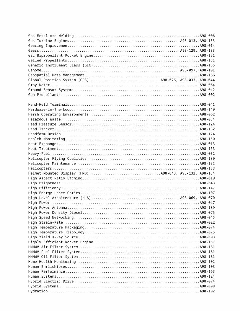
Personnel.........................................................................................................................................................................A98-086Phage Display..................................................................................................................................................................A98-143Phase Tunable Spatial Light Modulator (SLM)................................................................................................................A98-021Photolithography.............................................................................................................................................................A98-057Photon-Molecule Interactions..........................................................................................................................................A98-027Photorealism.................................................................................................................................................................... A98-073Phototool.........................................................................................................................................................................A98-057Physical Vapor Deposition...............................................................................................................................................A98-004Pilot-Vehicle Task Analysis.............................................................................................................................................A98-130Pintle............................................................................................................................................................................... A98-059Pixel by Pixel Manufacturing...........................................................................................................................................A98-025Pixel Demixing................................................................................................................................................................A98-091Plasma Diagnostics..........................................................................................................................................................A98-027Plasma/High Velocity Oxyfuel Coatings..........................................................................................................................A98-006Plasmodium Falciparum...................................................................................................................................A98-097, A98-101Platelet Additives.............................................................................................................................................................A98-100Platelets...........................................................................................................................................................................A98-100Platelets Processor...........................................................................................................................................................A98-100Polarization Filter............................................................................................................................................................A98-120Polymers.......................................................................................................................................................................... A98-156Portable........................................................................................................................................................................... A98-136Portable Nitrogen Generating Cart...................................................................................................................................A98-135Position...........................................................................................................................................................................A98-044Positioning....................................................................................................................................................................... A98-137Post-Processing................................................................................................................................................................A98-148Power Electronics Cooling...............................................................................................................................................A98-074Power Generation............................................................................................................................................................A98-085Power Management.........................................................................................................................................................A98-136Power Rectifier................................................................................................................................................................A98-074Power Sources................................................................................................................................................................. A98-085Pressure Controlling Pintle..............................................................................................................................................A98-151Pressure Regulators.........................................................................................................................................................A98-023Printed Wiring Board.......................................................................................................................................................A98-057Prioritization....................................................................................................................................................................A98-108Processing.......................................................................................................................................................................A98-078Prophylaxis...................................................................................................................................................................... A98-101Propulsion........................................................................................................................................A98-032, A98-133, A98-151Protective Materials.........................................................................................................................................................A98-024Proximity Fuze................................................................................................................................................................A98-113
Q-Switched...................................................................................................................................................................... A98-147Quantum Dots..................................................................................................................................................................A98-028Quantum Well................................................................................................................................................................. A98-009
Radar...............................................................................................................................................................A98-104, A98-106Radar Technology............................................................................................................................................................A98-117Radio...............................................................................................................................................................A98-010, A98-087Radio Frequency Communication....................................................................................................................................A98-109Radio Frequency Countermeasure Antennas....................................................................................................................A98-048Radiography.................................................................................................................................................................... A98-007Radiowave Propogation...................................................................................................................................................A98-035Rapid Diagnosis...............................................................................................................................................................A98-098Rapid Re-Training ATR...................................................................................................................................................A98-058Rapid Toxicity Assessment..............................................................................................................................................A98-168Rate Gyros....................................................................................................................................................................... A98-061Rate Sensors....................................................................................................................................................................A98-061RCS.................................................................................................................................................................................A98-033Re-Baselining..................................................................................................................................................................A98-054Re-Use.............................................................................................................................................................................A98-153Real-Time........................................................................................................................................................A98-035, A98-044Real-Time Biomolecular Analysis...................................................................................................................................A98-143Real-Time Control...........................................................................................................................................................A98-110Real-Time Infrared Scene Projection...............................................................................................................................A98-149Real-Time Sensor............................................................................................................................................................A98-127
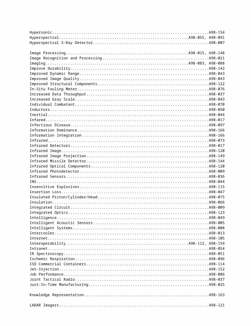
Real-Time Simulation.......................................................................................................................A98-070, A98-077, A98-158Real-Time Variable Bit Rate (RT-VBR)..........................................................................................................................A98-045Realism...........................................................................................................................................................................A98-159Receive............................................................................................................................................................................ A98-047Rechargeable Battery.......................................................................................................................................................A98-138Rechargeable Power Supply.............................................................................................................................................A98-036Recognition/Identification...............................................................................................................................................A98-125Recombinant Antibody....................................................................................................................................................A98-143Rectified Imagery............................................................................................................................................................A98-092Recycling......................................................................................................................................................................... A98-064Reduced Weight..............................................................................................................................................................A98-043Reference Architecture....................................................................................................................................................A98-112Reflectance......................................................................................................................................................................A98-055Refraction........................................................................................................................................................................ A98-169Refractory Materials........................................................................................................................................................A98-019Refractory Metals and Ceramics......................................................................................................................................A98-025Remote "Non-Contact" Environmental Sensing...............................................................................................................A98-109Remote Driving...............................................................................................................................................................A98-073Remote Sensing...............................................................................................................................................................A98-051Remote Sensors...............................................................................................................................................................A98-109Remote Video Receiver...................................................................................................................................................A98-036Renewable.......................................................................................................................................................................A98-140Repository....................................................................................................................................................................... A98-112Reserve Parachute Activation..........................................................................................................................................A98-065Residual Stress................................................................................................................................................................A98-129Resin Transfer Molding...................................................................................................................................................A98-078Resonators....................................................................................................................................................................... A98-050Respirator Wear...............................................................................................................................................................A98-145Reusable Components......................................................................................................................................................A98-112Reverse Osmosis..............................................................................................................................................................A98-076RF Jamming.................................................................................................................................................................... A98-033Rheology..........................................................................................................................................................A98-002, A98-096Rheology Study of Thermoplastic and Thermoset............................................................................................................A98-002Rickettsial........................................................................................................................................................................ A98-103Risk Management............................................................................................................................................................A98-054Robotics...........................................................................................................................................................A98-016, A98-111Rocket Engine.................................................................................................................................................................A98-151Rocket Engine Testing.....................................................................................................................................................A98-151Rocket Motor...................................................................................................................................................................A98-059Rocky Mountain Spotted Fever........................................................................................................................................A98-103Rotary Wing Platforms....................................................................................................................................................A98-141Rotorcraft........................................................................................................................................................................ A98-014Rotorcraft Noise Abatement.............................................................................................................................................A98-031
Sampling......................................................................................................................................................................... A98-146SAR................................................................................................................................................................................. A98-104Satellite........................................................................................................................................................................... A98-056Screening Level Toxicity.................................................................................................................................................A98-168Scrub Typhus................................................................................................................................................................... A98-103Seamless Architecture......................................................................................................................................................A98-153Security........................................................................................................................................................................... A98-045SEDRIS........................................................................................................................................................................... A98-159Selectivity........................................................................................................................................................................ A98-047Self-Assembly................................................................................................................................................................. A98-028Semiconductors...............................................................................................................................................................A98-020Sensor.................................................................................A98-044, A98-053, A98-055, A98-065, A98-078, A98-150, A98-164Sensor Cross-Cueing........................................................................................................................................................A98-049Sensor Emplacement........................................................................................................................................................A98-005Sensor Fusion.................................................................................................................................................................. A98-110Sensor Network...............................................................................................................................................................A98-036Sensor/Signal Processing Architecture.............................................................................................................................A98-042Separated Flows...............................................................................................................................................................A98-152Sequence Analysis Methods.............................................................................................................................................A98-097Shelters............................................................................................................................................................................A98-066
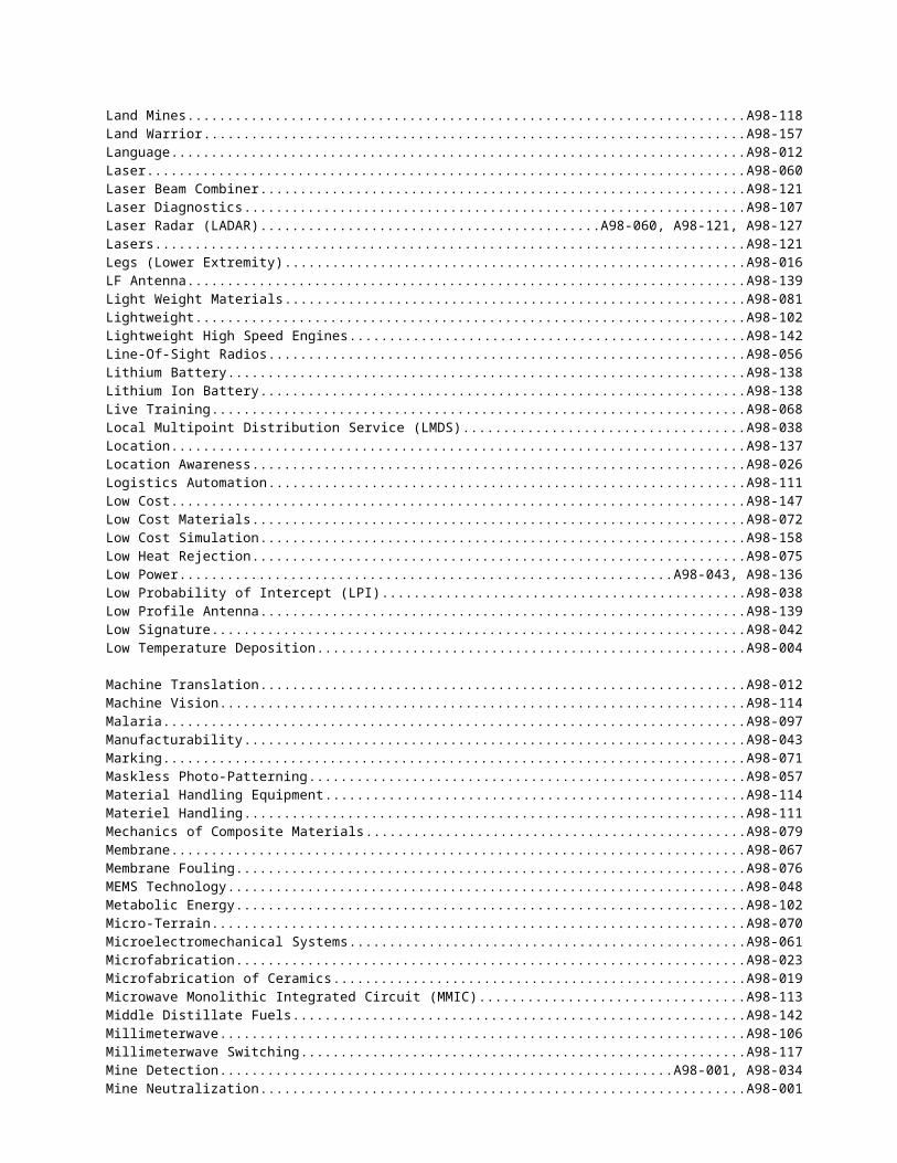
Shock............................................................................................................................................................................... A98-082Shock Damage.................................................................................................................................................................A98-061Shock Sensors..................................................................................................................................................................A98-061Short Wavelength Optics.................................................................................................................................................A98-020Short-Term Toxicity Test.................................................................................................................................................A98-168Si3N4 Processing..............................................................................................................................................................A98-019SiC.................................................................................................................................................................................. A98-025Signal Processing.............................................................................................................................................................A98-136Signature Enhancer..........................................................................................................................................................A98-125Silicon Carbide................................................................................................................................................................A98-074Silicon Carbide Processing..............................................................................................................................................A98-019Simulation........................................................................................................................................A98-068, A98-086, A98-130Simulation Based Acquistion............................................................................................................A98-080, A98-145, A98-160SiN.................................................................................................................................................................................. A98-025Situation Assessment and Target Reporting.....................................................................................................................A98-005Skill Assessment..............................................................................................................................................................A98-086Skirts............................................................................................................................................................................... A98-081Sled Tracks...................................................................................................................................................................... A98-082Small Unit Operations.....................................................................................................................................................A98-157Smart Fabric.................................................................................................................................................................... A98-063Smart Imager...................................................................................................................................................................A98-148Smart Materials...............................................................................................................................................................A98-110Smart Propulsion.............................................................................................................................................................A98-151Smart Radio..................................................................................................................................................................... A98-037SMDBL........................................................................................................................................................................... A98-105SMDC............................................................................................................................................................................. A98-105Software Agents..............................................................................................................................................................A98-008Software Measurement....................................................................................................................................................A98-054Software Programmable...................................................................................................................................................A98-037Solar Power..................................................................................................................................................................... A98-036Soldier Performance........................................................................................................................................................A98-145Solid Propulsion..............................................................................................................................................................A98-059Solid State X-Ray Detector..............................................................................................................................................A98-007Solid-State Laser.............................................................................................................................................................A98-060Space...............................................................................................................................................................................A98-105Spatial Light Modulation for IR Scene Projection............................................................................................................A98-149Specialty Optics...............................................................................................................................................................A98-107Spectral Contrast.............................................................................................................................................................A98-055Spectrum Efficiency........................................................................................................................................................A98-037Speech Recognition.........................................................................................................................................................A98-052Spring Motor................................................................................................................................................................... A98-140Stand-Off Armor..............................................................................................................................................................A98-072Standardization................................................................................................................................................A98-069, A98-159Standoff Detection...........................................................................................................................................................A98-144Station Keeping...............................................................................................................................................................A98-034Stereo Vision................................................................................................................................................................... A98-073Storage............................................................................................................................................................................ A98-166Stress Emotion.................................................................................................................................................................A98-163Strontium-Fluoroapatite...................................................................................................................................................A98-147Structural Analysis..........................................................................................................................................................A98-154Structures........................................................................................................................................................................A98-029Sub-Surface.....................................................................................................................................................................A98-088Superplastic..................................................................................................................................................................... A98-022Supersonic....................................................................................................................................................................... A98-154Surveillance System.........................................................................................................................................A98-036, A98-042Survivability....................................................................................................................................................................A98-141Switches.......................................................................................................................................................................... A98-050Symbology......................................................................................................................................................................A98-132Synthetic Aperture Radar.................................................................................................................................................A98-104Synthetic Environment.....................................................................................................................................................A98-160Synthetic System Design.................................................................................................................................................A98-160
Tactical Communications................................................................................................................................................A98-010Tactical Decisions Aid.....................................................................................................................................................A98-005
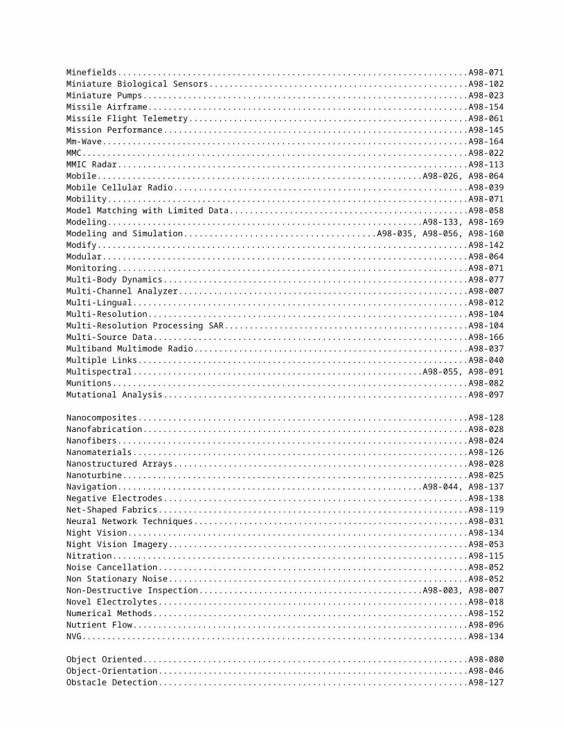
Tactical Engagement Systems..........................................................................................................................................A98-068Target Detection..............................................................................................................................................................A98-042Target Knowledge Base Updating....................................................................................................................................A98-058Target Model Reference Generation.................................................................................................................................A98-058Technical Architecture.....................................................................................................................................................A98-112Technology Insertion.......................................................................................................................................................A98-162Telecommunications........................................................................................................................................A98-010, A98-038Telemetry.........................................................................................................................................................A98-061, A98-102Telepresence.................................................................................................................................................................... A98-040Telerobotic Operation......................................................................................................................................................A98-114Telescoping Air Cleaner Intake........................................................................................................................................A98-161Tentage............................................................................................................................................................................ A98-156Tents................................................................................................................................................................................ A98-066Terrain.............................................................................................................................................................A98-071, A98-159Terrain Databases............................................................................................................................................................A98-157Terrain Mapping Sensor...................................................................................................................................................A98-118Terrain Model..................................................................................................................................................................A98-035Terrain Reasoning............................................................................................................................................................A98-046Test Evaluation and Repair..............................................................................................................................................A98-150Textiles............................................................................................................................................................................A98-066Thawed Platelets..............................................................................................................................................................A98-100Thermal........................................................................................................................................................................... A98-066Thermal Analysis.............................................................................................................................................................A98-154Thermal Management......................................................................................................................................................A98-062Thermal Protection Systems............................................................................................................................................A98-154Thermal-Mechanical Design............................................................................................................................................A98-062Thermoplastic..................................................................................................................................................................A98-002Thermoset........................................................................................................................................................................A98-002Thin-Film Deposition......................................................................................................................................................A98-027Throttling Rocket Engine.................................................................................................................................................A98-151Through Wall Surveillance..............................................................................................................................................A98-034Tin Oxide........................................................................................................................................................................A98-138Tissue Viability...............................................................................................................................................................A98-096Titanium..........................................................................................................................................................................A98-006Titanium Alloys...............................................................................................................................................................A98-122Topographic Understanding.............................................................................................................................................A98-046Traffic and Congestion Control........................................................................................................................................A98-045Trailing Shield.................................................................................................................................................................A98-006Training........................................................................................................................................................................... A98-069Training Device...............................................................................................................................................................A98-068Transmission................................................................................................................................................................... A98-014Transmit..........................................................................................................................................................................A98-047Transparent Armor...........................................................................................................................................................A98-128Transportation.................................................................................................................................................................A98-082Trend Analysis.................................................................................................................................................................A98-054Tunable Electronic Filters................................................................................................................................................A98-050Turbine Blades/Vanes......................................................................................................................................................A98-129Turbines..........................................................................................................................................................................A98-133Turboshaft Engine...........................................................................................................................................................A98-129Turbulence Models..........................................................................................................................................................A98-152Turret Mounted Systems..................................................................................................................................................A98-053Two-Phase Gas Particle Flow..........................................................................................................................................A98-152
U-Nii-Band...................................................................................................................................................................... A98-038UAV................................................................................................................................................................A98-030, A98-032Ultraviolet....................................................................................................................................................................... A98-164Unattended Ground Sensor..............................................................................................................................................A98-144Underwater Imaging........................................................................................................................................................A98-083Unstructured Grids...........................................................................................................................................................A98-152Upgrade...........................................................................................................................................................................A98-142
Valve...............................................................................................................................................................................A98-023Variable Thrust Rocket Engine........................................................................................................................................A98-151Vector Feature.................................................................................................................................................................A98-049
Vector Feature Data.........................................................................................................................................................A98-092Vector Product Format.....................................................................................................................................................A98-092Vehicle Subsystem Models..............................................................................................................................................A98-077Vehicle Upgrade..............................................................................................................................................................A98-072Versa Modula Europa Extensions For Instrumentation.....................................................................................................A98-155Vertical Cavity Surface Emitting Array...........................................................................................................................A98-062VHDL Code.....................................................................................................................................................................A98-056VHF/UHF Antenna..........................................................................................................................................................A98-139Vibration......................................................................................................................................................................... A98-082Vibration Sensors............................................................................................................................................................A98-061Video............................................................................................................................................................................... A98-137Virtual.............................................................................................................................................................................A98-040Virtual Environment.........................................................................................................................................A98-070, A98-158Virtual Individual Combatant...........................................................................................................................................A98-157Virtual Product Development...........................................................................................................................................A98-080Virtual Prototyping..........................................................................................................................................................A98-080Virtual Reality..................................................................................................................................A98-131, A98-132, A98-157Viruses............................................................................................................................................................................ A98-099Visual.............................................................................................................................................................................. A98-137Visual Display.................................................................................................................................................................A98-073Visualization....................................................................................................................................................A98-040, A98-145VLSI Circuit Technology.................................................................................................................................................A98-015
Waste Water.................................................................................................................................................................... A98-064Water Pretreatment..........................................................................................................................................................A98-076Waterway Navigation......................................................................................................................................................A98-034Waveguides.....................................................................................................................................................................A98-050Weapon Detection...........................................................................................................................................................A98-034Weapon Stabilization Sensors..........................................................................................................................................A98-110Weather........................................................................................................................................................................... A98-106Weaving Process..............................................................................................................................................................A98-119Web................................................................................................................................................................................. A98-105Wide-Band Antenna.........................................................................................................................................................A98-139Wideband Power Amplifiers............................................................................................................................................A98-050Wind Noise......................................................................................................................................................................A98-116WINLABS Infostation.....................................................................................................................................................A98-038Wireless Networks...........................................................................................................................................................A98-026
X-Ray Generation............................................................................................................................................................A98-003X-Ray Tube.....................................................................................................................................................................A98-003
Zirconia........................................................................................................................................................................... A98-025Zrb2.................................................................................................................................................................................A98-025
INDEX OF ARMY FY99 TOPICS
U.S. Army Armaments Research, Development and Engineering Center (ARDEC)
A98-001 Acoustic Mine Detection and NeutralizationA98-002 Rheology Study of Thermoplastic and Thermoset Elastomer-Based Gun Propellants for the
Advanced Weapon SystemsA98-003 High Yield X-ray SourceA98-004 Deposition of Crystalline Alumina Films at Low TemperaturesA98-005 Tactical Decision Aids for Intelligent Acoustic SensorsA98-006 Plasma/High-Velocity Oxyfuel Deposited Coatings for TitaniumA98-007 Hyperspectral X-ray DetectorA98-008 Intelligent Multi-Agent Hybrid Systems Control TechnologyAlso see OSCR topics A98-109 thru A98-115Also see OSCR topics A98-109 thru A98-115
U.S. Army Research Laboratory (ARL)
A98-009 Advanced Read-Out Integrated Circuit for a Quantum Well Infrared Photodetector ArrayA98-010 Innovative Methods for Mobile Frequency Hopping Radio NetworksA98-011 Electrochemical Energy Storage Components (Batteries and Capacitors)A98-012 Multi-lingual Retrieval SystemA98-013 Advanced, Ultra Compact Heat ExchangersA98-014 Analysis and Design Tools for Rotorcraft TransmissionsA98-015 Opto-Silicon-Integrated Elements for High-Resolution Wavefront Control and Real-Time
Image ProcessingA98-016 Lower Extremity Enhancer for SoldiersA98-017 Novel Infrared (IR) Detector CoolingAlso see OSCR topics A98-116 thru A98-128
U.S. Army Research Office (ARO)
A98-018 Miniature Support Devices for Portable Power ApplicationsA98-019 Electrosynthesis of Materials in Novel Solvent/Electrolyte MediaA98-020 Short Wavelength Integrated Optic ComponentsA98-021 Phase Tunable Spatial Light ModulatorA98-022 High Strain-rate, Super Plastic Forming of Metals, Alloys and CompositesA98-023 Microfabricated Refractory Materials for Portable Power ApplicationsA98-024 Nanofibers for Soldier ProtectionA98-025 Desktop Manufacturing of Refractory MaterialsA98-026 Enhancements to Mobile, Wireless Network Services Based On Location AwarenessA98-027 Reactive Plasma Diagnostics for Gas Agent Sensors or Thin-Film Materials ModificationA98-028 Biomolecular Construction of Quantum Dots
U.S. Army Aviation Research, Development and Engineering Center (AVRDEC)
A98-029 Fatigue Strength Modeling of Composite Bonded Joints for Rotary Wing StructuresA98-030 Passive/Low Probability of Intercept Collision Avoidance and Airspace Deconfliction for
Unmanned Aerial Vehicles (UAV) OperationsA98-031 Rotorcraft Ground Noise Exposure Prediction System Using Neural NetworksA98-032 Lightweight Heavy Fuel Engines for Unmanned Aerial Vehicles (UAV)A98-033 Enhanced A/J Performance GPS FRPA Antenna and ElectronicsAlso see OSCR topics A98-129 thru A98-135
U.S. Army Communications and Electronics Command (CECOM)
A98-034 Passive Millimeter Wave Imaging CameraA98-035 Near Real-time Visualization of RF Propagation Terrain ModelsA98-036 Unattended Miniature Sensors
A98-037 Spectrum Efficiency in Smart RadiosA98-038 Low-cost Broadband AJ/LPI Interactive U-NII /LMDS-based Communication
TransceiverA98-039 Direction-Finding for Second-Generation Mobile Cellular Radio/Personnel
Communication ServiceA98-040 Collaboration and Visualization in a Virtual EnvironmentA98-041 Hand-held Terminal for Battlefield BroadcastA98-042 Detection of Low Signature Moving TargetsA98-043 Low-Power, Analog-Drive, Helmet-Mounted DisplayA98-044 Position Displacement SensorA98-045 Secure, Compressed, Multimedia Data over Variable Bit Rate, ATM Adaptation Layer
(AAL) AlgorithmA98-046 Object-Oriented Contour Map Database to Support IEW and C2 ApplicationsA98-047 Cosite InterferenceA98-048 New Antenna Materials and TechnologiesA98-049 Electromagnetic and Cultural Feature Cross-CueingA98-050 Thick-film Metalization for Miniaturized Communications Components and SubsystemsA98-051 New Approaches to Chemical Identification in Remote Sensing FTIR (Fourier Transform
Infrared) SpectroscopyA98-052 Speech Recognition Enhancement Through Digital Signal Noise Processing (DSNP)A98-053 Colorizing Low Light Imaging (Color Night Vision Goggles)A98-054 Intranet-Based Software Measurement ToolsetA98-055 Narrow Band Spectral Color and NIR MatchingA98-056 Turbo Code ApplicationsAlso see OSCR topics A98-136 thru A98-142
U.S. Army Missile Research, Development and Engineering Center (MRDEC)
A98-057 High Speed Non-Contact Maskless Patterning System for Printed Wiring BoardsA98-058 Rapid Updating of Target Knowledge Base for Automatic Target RecognitionA98-059 Miniaturized, Low Cost, High Performance Pintle Actuation And Control System For A
Pintle Solid Propellant Rocket MotorA98-060 Compact, High Average Power, Eyesafe Laser DevelopmentA98-061 Microsensors for Measuring Angular Velocity in High Frequency Shock and Vibration
EnvironmentsA98-062 High Reliability Optoelectronic Array Packaging for Parallel Optical CommunicationAlso see OSCR topics A98-148 thru A98-155
U.S. Army Natick Research, Development and Engineering Center (NRDEC)
A98-063 Advanced Parachute/Fabric Performance Measurement TechnologyA98-064 Gray Water Treatment SystemA98-065 Sensors/Initiators for Automatic Activation of Parachutes for both Static Line and
Freefall ApplicationsA98-066 Energy Efficient Tentage with Reduced Thermal SignatureA98-067 Electrically Polarizable Materials for Chemical/Biological ProtectionAlso see OSCR topic A98-156
U.S. Army Simulation, Training and Instrumentation Command (STRICOM)
A98-068 NonSystem Training Device and Training Instrumentation Systems/TechnologyA98-069 Advancement in Simulation and High Level Architecture (HLA) Infrastructure and
Distance Learning Tool DevelopmentA98-070 Advancements in Individual Combatant Simulation TechnologyAlso see OSCR topics A98-157 thru A98-160
U.S. Army Tank-Automotive Research, Development and Engineering Center (TARDEC)
A98-071 Combat Engineer Mobility AwarenessA98-072 Encapsulation of Ceramic Plates with Elastomeric Materials for Ballistic Armor
ApplicationsA98-073 Visual Display for Remote Operation of Robotic Ground VehiclesA98-074 Hybrid Propulsion Vehicle Power Conditioning Devices and PackagingA98-075 High Power Density Diesel Propulsion TechnologyA98-076 Reverse Osmosis Membrane Inhibition TechniquesA98-077 Interactive (Real-time) Vehicle Subsystem Models Supporting System Dynamics
Performance ModelsA98-078 Innovative Sensor Technology DevelopmentA98-079 21st Century Truck/Military Vehicle Structural Design ToolsA98-080 Robust 3-D Surface Model RepresentationA98-081 Develop Ceramic Composite Materials for Vehicle Fenders and Ballistic Skirts at
Reduced WeightAlso see OSCR topics A98-161 thru A98-162
U.S. Army Test and Evaluation Command (TECOM)
A98-082 Reduction in the Shock/Vibration Levels Experienced During Dynamic Warhead TestingA98-083 Underwater High Speed ImagingA98-084 Portable Heavy Metals Spectral AnalyzerA98-085 Alternative Power for Remote Site Optics
U.S. Army Research Institute (ARI)
A98-086 Simulation Technology for Performance AssessmentAlso see OSCR topic A98-163
U.S. Army Construction Engineering Research Laboratory (CERL)
A98-087 Structural Bracing for Seismic Energy DissipationA98-088 Near Surface Imaging In Soils for Archeological AssessmentsAlso see OSCR topic A98-164
U.S. Army Cold Regions Research and Engineering Laboratory (CRREL)
A98-089 Range-Resolved Inflight Air Temperature SensingA98-090 Rapid Stabilization of Soft Ground Surfaces By Artificial FreezingAlso see OSCR topic A98-165
U.S. Army Topographic Engineering Center (TEC)
A98-091 Multi-Sensor Exploitation Capabilities Enhancements for an Autonomous Analysis/Exploitation System
A98-092 Legacy Map Data Exploitation ToolsAlso see OSCR topic A98-166
U.S. Army Waterways Experiment Station (WES)
A98-093 Battlefield Environment Signature Transformations Using Electrochromic DevicesA98-094 Device for Testing the Response of Conventional Building Components to Blast Loads
from Vehicle BombsAlso see OSCR topic A98-167
U.S. Army Medical Research and Materiel Command (MRMC)
A98-095 Dental Operating And Treatment Unit, Electric Motor Handpiece, Powered By Rechargeable DC Battery and AC
A98-096 Lightweight, Portable, Non-Invasive Physiologic Sensors For Multi-Site Determination/Quantitation Of Surface & Deep Tissue Microvascular Blood Flow
A98-097 DNA/Gene Chip TechnologyA98-098 Advanced Diagnostic Devices for Biological Agent IdentificationA98-099 Rapid Tests For Transfusion Transmissible Diseases To Support Emergency Blood
TransfusionA98-100 Thawed Platelet Processing SystemA98-101 Multidisciplinary Approaches to Antimalarial Structure-Based Drug Discovery:
Incorporating Bioinformatics & Combinatorial ChemistryA98-102 Physiologic Sensors For Ambulatory MonitoringA98-103 Development of a Rapid, Sensitive & Specific Antibody Detection System to Facilitate
Diagnosis of Ehrlichial and Rickettsial DiseasesAlso see OSCR topic A98-168
U.S. Army Space and Missile Defense Command (SMDC)
A98-104 Multiband, Multi-resolution Synthetic Aperture RadarA98-105 Space Products Internet Prototype (SPIP)A98-106 Real-Time Weather Clutter Avoidance for Millimeter Wavelength RadarsA98-107 High Energy Laser Optical and Diagnostic DevelopmentA98-108 Innovative Decision AidAlso see OSCR topic A98-169
Topics Addressing U.S Army Operating and Support Cost Reduction (OSCR) InitiativesTopics Addressing U.S Army Operating and Support Cost Reduction (OSCR) Initiatives
U.S. Army Armaments Research, Development and Engineering Center (ARDEC)
A98-109 Remote Non-Contact Environmental Sensing and Communication DeviceA98-110 Advanced Sensors for Weapon Stabilization and Fire ControlA98-111 Adaptable/Reusable Hardware/Software Architectures and Components for Automated
Materiel HandlingA98-112 Software Infrastructure/Reuse Technology for Embedded ApplicationsA98-113 Low-Power, Integrated Radar Proximity Sensor for FuzingA98-114 Sight Based Container Handling Equipment (SB-CHE)A98-115 Develop New Nitration Methods for Insensitive Energetic Materials
U.S. Army Research Laboratory (ARL)
A98-116 Wind Noise ReductionA98-117 Millimeter Wave (MMW) Crossbar Switching for Multi-Beam Electronic Scanning
Antenna TechnologyA98-118 Countermine Vehicle Terrain Mapping SensorA98-119 Advanced Weaving Process For Net-Shape Fabrics Having Tailored Fiber Architecture
And Non-Planar ShapesA98-120 Development of a Modulated Polarization Filter for Infrared ImagingA98-121 High Power Laser Beam CombinerA98-122 Low Cost Titanium Alloy Components for Armor and Structural ApplicationsA98-123 Lossless Integrated Optical SplitterA98-124 Head Pressure Analysis SystemA98-125 Active/Passive Signature Enhancer (APSE)A98-126 Characterization Of NanomaterialsA98-127 Obstacle Detection Laser RadarA98-128 Novel Transparent Nanocomposites
U.S. Army Aviation Research, Development and Engineering Center (AVRDEC)
A98-129 Advanced Materials for Helicopter Propulsion SystemsA98-130 Helicopter Pilotage Task Analysis and Modeling to Reduce Cost and Improve Handling
Qualities/SafetyA98-131 Application of Virtual Technology in Army Helicopter MaintenanceA98-132 Advanced Head Tracking DevelopmentA98-133 Turboshaft Engine TechnologyA98-134 Device for Measuring Performance and Defects in Binocular DisplaysA98-135 Lightweight, Portable Nitrogen Generator
U.S. Army Communications and Electronics Command (CECOM)
A98-136 Low-Power Consumption Computing DevicesA98-137 Navigation/Electro-Optic Sensor Integration Technology (NEOSIT)A98-138 Advanced High-Energy Negative Electrodes for Lithium-ion BatteriesA98-139 High Power Transmit/Receive Antenna for Airborne ApplicationsA98-140 Coiled Spring Motor-Driven Power System for Small LoadsA98-141 Acoustic Signature Reduction of Rotary Wing AircraftA98-142 Improve / Enhance Durability of Small, Lightweight 6 - 25 HP Engines
U.S. Army Edgewood Research, Development and Engineering Center (ERDEC)
A98-143 Automated Real Time Screening Of Recombinant Phage Displayed Libraries
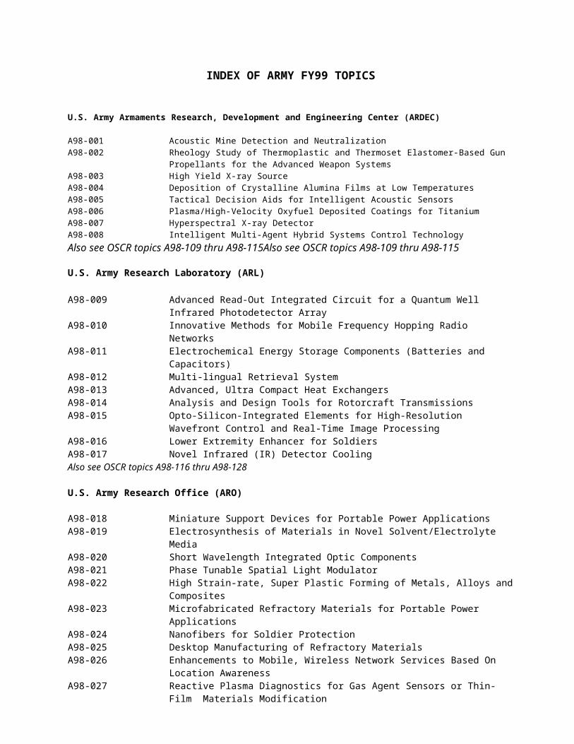
A98-144 Upward Looking Unattended Ground Sensor For Enhanced Stand-Off Chemical Detection
A98-145 Soldier Chemical and Biological Defense Protective Equipment Design and Product Evaluation Tool
A98-146 Development Of A Light Weight Sampler For Biological AgentsA98-147 Modeling of Flow Dynamics for Mask Design Optimization
U.S. Army Missile Research, Development and Engineering Center (MRDEC)
A98-148 High Speed Camera With On Board Generation Of Regions Of InterestA98-149 Application of Spatial Light Modulators to Infrared Scene Projection for Hardware-in-
The-Loop Simulation and TestingA98-150 Structural Evaluation of Composite SystemsA98-151 Throttling Gel Bipropellant EngineA98-152 Divert & Attitude Control Solid Propellant Jet-Interaction ModelingA98-153 Develop Advanced System Tools To Automate Test Program Set (TPS) Re-HostA98-154 Development Of Software To Provide Aerothermal And Pressure Loading Boundary
Conditions For Nonaxisymmetric, Three Dimensional, Supersonic And Hypervelocity Airframes
A98-155 Generic Instrument Class (GIC)
U.S. Army Natick Research, Development and Engineering Center (NRDEC)
A98-156 Thin Layer Fiber Encapsulation Technology
U.S. Army Simulation, Training and Instrumentation Command (STRICOM)
A98-157 Embedded Simulation for Individual Combatant Mission Planning and RehearsalA98-158 Low Cost PC Based Real-Time Dynamic TerrainA98-159 Virtual Terrain Database Correlation ResearchA98-160 Advancements in Simulation Based Acquisition
U.S. Army Tank-Automotive Research, Development and Engineering Center (TARDEC)
A98-161 Increase of Service Life for Filtration System Components on Military VehiclesA98-162 Compression Ignition Engine Technology Insertion
U.S. Army Research Institute (ARI)
A98-163 Improving Soldier Factors in Prediction Models
U.S. Army Construction Engineering Research Laboratory (CERL)
A98-164 Self Healing Coatings and Materials Using Nanocapsules
U.S. Army Cold Regions Research and Engineering Laboratory (CRREL)
A98-165 Land-Based, High Resolution Acoustic Sounder
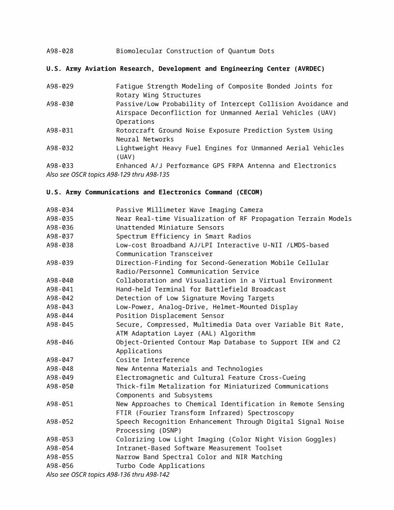
U.S. Army Topographic Engineering Center (TEC)
A98-166 Multi-Source Data Integration Supporting Common Geo-Environmental Representation and Analysis
U.S. Army Waterways Experiment Station (WES)
A98-167 Determining Capacity of Military Pavements
U.S. Army Medical Research and Materiel Command (MRMC)
A98-168 Rapid Acute Toxicity Screening
U.S. Army Space and Missile Defense Command (SMDC)
A98-169 Investigation of Error Sources in the ALTAIR Real-Time Refraction- Correction Model
ARMY FY 98.2 TOPICS
U.S. Army Armaments Research, Development and Engineering Center (ARDEC)
A98-001 TITLE: Acoustic Mine Detection and Neutralization
KEY TECHNOLOGY AREA: Electronic Warfare/Directed Energy Weapons
OBJECTIVE: Develop a system capable of acoustically detecting and neutralizing existing and next-generation land mines.
DESCRIPTION: There is a growing need for the ability to efficiently and effectively detect and dispose of land mines. This is based upon the growing concern over the number of land mines that have been left after conflicts, and the number of civilian casualties as a result of these uncleared areas. This problem has been aggravated by the increased sophistication of land mines and reduced ability to detect them due to the use of new materials in their construction. Current systems either cannot detect new land mine systems, or the detection times are too long and not reliable, and thereby are virtually prohibitive. A system is needed to acquire and then disable these new and existing land mines in a fraction of the time currently achievable, and with a relatively small rate of false alarms.
PHASE I: Identify existing acoustic detection systems which are potential candidates to identify land mines. In addition determine the sensitivity of the mine initiation process to acoustic energy and determine the vulnerable thresholds for certain components, subsystems, and the total system for various mines. Experimentally confirm/verify the sensitivity analysis by utilizing current mines or representative components for different classes of mines.
PHASE II: Combine the two (2) systems developed independently during Phase I into a single brassboard system. In addition, experimentally confirm/verify the capability to detect and neutralize several representative land mines.
PHASE III DUAL-USE APPLICATIONS: This technology has numerous applications in the areas of law enforcement and counter terrorism. This technology could be utilized either in the joint mode of detection and neutralization or each mode independently. For buildings or areas requiring constant monitoring for munitions activities, this device could store an acoustic footprint of the building/area, and via comparison of the current trace to the baseline data, a proactive counter terrorist effort could be initiated or maintained. This device could provide protection to safeguard buildings or areas and still enable authorized personnel entrance when necessary.
A98-002 TITLE: Rheology Study of Thermoplastic and Thermoset Elastomer-Based Gun Propellants for the Advanced Weapon Systems
KEY TECHNOLOGY AREA: Weapons Technology
OBJECTIVE: Determine the rheological properties of Energetic Thermoplastic (TPE) and Thermoset (TSE) Elastomers Binder-based propellants incorporating energetic fillers such as RDX (Cyclonite), HMX (Hexamethylene Tetramine), CL 20 (Hexanitrohexaazaisowurtzitane) and TNAZ (1,3,3, Trinitroazetidine) to support the development and production of advanced high energy propellants for use in the advanced weapon system for tanks and artillery.
DESCRIPTION: Recent advanced development work in Thermoplastic and Thermoset elastomer-based gun propellants has demonstrated that they can satisfactorily perform ballistically when compared with propellants currently in use. In addition, these propellants have low flame temperatures and have minimal environmental processing problems. There are still several unanswered questions as to the processing and producibility of these types of thermoplastic and thermoset elastomer based propellants. These questions include rheologicalbehavior in die entrance and exit effects, wall slip effects, wall shear stress effects, die L/D ratios, and shear viscosity.
PHASE I: Conduct a literature review and small scale rheological study and test using the capillary rheometer with inert and live formulations by using different L/D ratios of dies, different particle size of fillers such as RDX, HMX, and CL 20 at variable temperature conditions. Rheological data such as die entrance and exit effects, wall slips effect, shear stress on the wall, die L/D ratios and shear viscosity that are necessary for the processing and reproducibility of a TPE and TSE based propellant and explosive formulations will be determined experimentally.
PHASE II: Conduct a large scale rheological study using the continuous twin screw extruder to verify dies L/D ratios and all the parameters obtained in Phase I of the study. In addition, a large scale slit die will be used to verify rheological data obtained from the capillary rheometer used in Phase I. Rheological data obtained from Phase I will be used to conduct computer simulation to design continuous twin screw extruder for the producibility of the TPE and TSE based propellant compositions. TPE and TSE based gun propellant compositions will be made using the large scale twin screw extruder to verify producibility using obtained rheological data from Phase I.PHASE III DUAL-USE APPLICATIONS: This rheological study could have wide utility, especially in the plastics industry involved with the manufacture of composite materials containing TPEs and TSEs. Dual use applications include automobile industry, medical supplies and equipment, clothing and textiles industry, commercial and residential building materials, household and office appliances and home utensils, man made shoes materials, and many others such as cosmetic kits, women s

jewelery, beauty kits and childrens toys.
REFERENCES:1. J.D. Ferry, Viscoelastic Properties of Polymers, 2nd Edition, John Wiley & Sons, Inc. 2. Z. Tadmor and C.G. Gogos, Principles of Polymer Processing, Copyright 1979, John Wiley & Sons, Inc.3. R. Byron Bird, R.C. Armstrong, and O. Hassager, Dynamics of Polymeric Liquids, Vol.I-Fluid Mechanics, 2nd Edition, John Wiley & Sons.
A98-003 TITLE: High Yield X-ray Source
KEY TECHNOLOGY AREA: Sensors
OBJECTIVE: To design and build an electronically generated X-ray source whose spectral composition is mainly the characteristic K and L lines of many elements and whose energy spread lies between 10 KeV and 200 KeV and whose efficiency of generation of x-rays exceeds 10% of the input wattage to the tube and whose physical size is less than conventional x-ray generators and whose total flux output is comparable to conventional tubes.
DESCRIPTION: Conventional electron tubes used for the generation of x-rays generally have as their target material or anode a single atomic element, e.g., tungsten. The x-ray spectrum emitted by such tubes consists of Bremsstrahlung plus the characteristics emission lines of the anode material. There exists evidence that anode composition and configuration have a greater effect on characteristic output line strength than previously thought. The proposal for this work must include a description of the anode, as well as the tube in general, the anodes composition and shape, and how the anode will be fabricated. The proposal must show evidence that the design has a good chance of meeting the objectives listed above. The x-ray tube should be compact; the smaller the better. The flux output should be at least 2 million photons per second per solid angle subtended by 2.5 EE -7 steradians. The output coverage angle should be about 60 degrees. The tube s efficiency should be great enough to require considerably less cooling than current tubes, preferably only ambient air cooling.
PHASE I: Demonstrate to Government witnesses the generation of x-rays from a mixture of heavy target (anode) materials using a laboratory experimental system. The demonstration should provide proof of principle that the Phase II design will meet the objectives of this solicitation. Create and deliver a design document for construction of a prototype x-ray source to be built in Phase II. Obtain documented commitment of capital funds for performing Phase III.
PHASE II: Develop, fabricate, demonstrate, and deliver a prototype meeting or exceeding the solicited objectives of output flux magnitude and spectral characteristics, efficiency, size, cooling requirements, etc. Develop a commercialization plan.
PHASE III DUAL-USE APPLICATIONS: An x-ray source of the solicited description will be an important element for systems which the Government is developing and which can identify the composition of objects such as energetic materials and contraband. Uses include: Process control where chemical composition must be remotely monitored. Process control of the congealing of material in the casting process. Process control over fabrication of composites and fiber embedded material. Non-destructive inspection of commercial and military energetic material. Non-destructive inspection of munition items. Accurate determination of material property such as density, composition, and crystallinity during productions processes. Finding and identifying contraband in luggage, briefcases, packages, parcels, containers. Medical uses should include mammography and osteoporosis.
A98-004 TITLE: Deposition of Crystalline Alumina Films at Low Temperatures
KEY TECHNOLOGY AREA: Materials, Process And Structures
OBJECTIVE: Insulating, transparent, hard and corrosion resistant coatings of crystalline Al 2O3 deposited at temperatures less than or equal to 300C. The DoD currently spends in excess of $10 Billion annually to fight corrosion. These coatings and processes are considered essential to TACOM-ARDEC for application to weapons systems, fire control and munitions items in order to lower their life cycle costs through reduced maintenance and support costs.
DESCRIPTION: The US Army has an interest in large area insulating ceramic coatings that are hard and corrosion resistant. Crystalline Al2O3 films having k- and, specially, a-crystalline phases, show extraordinarily high hot hardness, excellent high temperature resistance, and high stiffness. These films have properties useful for many applications ranging from optical waveguides to tribological and corrosion resistive coatings. The Army seeks to identify deposition technologies that would allow deposition of thin films of crystalline (k- or a-phase) on large area substrates heated to temperatures less than or equal to 300 C.
Presently Al2O3 coatings for cutting tools are produced mainly by chemical vapor deposition on substrates heated to temperatures of about 1000C. High substrate temperatures limit the range of materials that can be coated. Recent developments in physical vapor deposition (PVD) have shown that through the use of pulsed-power reactive sputtering (PPRS) thin films of k-Al2O3 can be deposited on substrates heated to temperatures of about 400C. These films showed excellent mechanical
performance. Al2O3 films deposited with ion-assisting bombardment showed high corrosion resistance. It can be expected that further development of PPRS and its combination with various ion-assisting deposition technologies would enable the manufacture Al2O3 films at even lower substrate temperatures. The goal of the proposed work should be manufacturing of corrosion resistive, stochiometric, crystalline Al2O3 films at made substrate temperatures of 300C or lower and having hardness of 12 GPa, elastic module of above 100 GPa, and a refractive index of 1.65.
PHASE I: Demonstrate feasibility of a PVD technology to deposit transparent, hard and corrosion resistant crystalline Al2O3 films on substrates heated to temperatures less than or equal to 300C.
PHASE II: Optimize corrosion resistance and mechanical and optical properties of Al 2O3 films varying the deposition conditions. The investigation should include detail characterization of corrosion resistance and mechanical and properties of these films. Identify and demonstrate practical applications for the developed crystalline Al 2O3.
PHASE III: Given that the private sector is also quite concerned with corrosion protection, extremely high potential for Dual-Use of this technology is expected. This effort will develop passivating, hard and thermally stable coatings on aluminum and steel parts identified and chosen in Phase II. This technology will be scaled-up and introduced into the market that will potentially include automobile and aircraft industries as well as manufacturers of optical and tool products.
A98-005 TITLE: Tactical Decision Aids for Intelligent Acoustic Sensors
KEY TECHNOLOGY AREA: Computing And Software
OBJECTIVE: To develop Tactical Decision Aids to assist the soldier in deploying and employing intelligent acoustic sensors under tactical conditions and in interpreting sensor surveillance reports under varied environmental and tactical conditions.
DESCRIPTION: The Army is increasing its emphasis on the use of passive intelligent acoustic sensors for battlefields of the 21st century. However, the complexity of the acoustic propagation environment and the extreme diversity of combat operations under which acoustic sensors may be employed have created an urgent need for decision aids to provide guidance in varied aspects of their use and interpretation of their reports. Because acoustic sensors exhibit widely varying performance characteristics as a function of the environment, a simple lookup table or soldier training alone will not be adequate for optimizing their tactical emplacement/deployment patterns. Additionally, acoustic surveillance reports from deployed intelligent accoustic sensors must be interpreted within the context of sensor characteristics, terrain, weather, tactical situation, overlapping sensor coverage, and target array size/formations.
Tactical Decision Aids for Intelligent Acoustic Sensors are required for the following:1. Sensor emplacement based upon atmospheric and terrain consideration.2. Deconfliction of target tracks for sensors/sensor arrays with overlapping coverage.3. Interpreting sensor data to draw conclusions on target array size and composition.4. Fusion of target reports with knowledge terrain characteristics, particularly when single sensors are employed and/or reporting.
These decision aids should allow for widely varying sensor designs, including both short- and long-range sensors, adaptive beam steering sensors, and sensors employed against both surface and air targets.
PHASE I: Develop and demonstrate sensors which satisfy each of the four Tactical Decision Aids requirements listed above. These demonstrations will be based upon at least two distinct sensor types with limited options for environmental and tactical conditions adequate for evaluation of the approach. During this phase the range of environmental conditions, terrain features, sensor characteristics, and target arrays will be defined.
PHASE II: The four Tactical decision Aids will be matured to address specific existing Army intelligent acoustic sensors (e.g. Remote Sentry, Raptor Intelligent Combat Outpost, Hunter-Sensor Suite, IREMBASS, etc.) and the full range of characteristics defined in Phase I. The tactical decision aids will be configured into a Graphical User Interface-based workstation/controller environment compatible with the Command, Control, Communications, Computers and Intelligence (C4I) Joint Tactical Architecture for exchange of situation assessment and target reporting information with Brigade and Below Command and Control. Final delivery will be into an Army Common Operating Environment (ACOE) onto Government Furnished Equipment (GFE) Common Hardware.
PHASE III DUAL-USE APPLICATIONS: All four of the Tactical Decision Aids being developed are largely non-specific to the fact that military targets are being tracked. The application of acoustic sensors for intrusion detection/tracking, such as large storage area depots, border surveillance, or monitoring of wilderness areas to detect unauthorized activity, has the same general requirements. These non-defense applications likewise consider environmental conditions, terrain features, sensor characteristics, and overlapping sensor target deconfliction to be effective. Thus Phase III opportunities exist for these decision aids wherever intelligent acoustic sensors are employed.
A98-006 TITLE: Plasma/High-Velocity Oxyfuel Deposited Coatings for Titanium
KEY TECHNOLOGY AREA: Materials, Process And Structures
OBJECTIVE: Develop a coating system and method of coating application for titanium which shields titanium weld metal and parent metal from atmospheric contamination during the welding process, yet can be removed easily after the welding process so that the coating is not permanent.
DESCRIPTION: The welding of titanium is difficult and expensive due to the reactive nature of the weld and parent metal. Since titanium is reactive with the atmosphere at temperatures above 800 Fahrenheit, welding of titanium must be conducted with supplemental gas shielding or inside an inert gas chamber. This supplemental shielding is costly, difficult to implement in certain designs, and makes the field welding of titanium nearly impossible. The cost and difficulty of welding titanium, therefore, has severely limited its application, especially in scenarios where field welding is necessary. We seek to address this problem by eliminating the need for supplemental gas shielding, for example by using a flux-type coating system applied to the weld to prevent contamination--this coating would then be later removed by either grinding or chipping. Developing a coating system and application technique would permit the welding of titanium without supplemental shielding, improving the range of application and lowering the cost of application.
PHASE I: Develop a coating system that inhibits the through diffusion of oxygen, nitrogen, and hydrogen into titanium at elevated temperatures (above 800 Fahrenheit). Demonstrate proof-of-principle of the design by coating test samples, exposing these test samples to elevated temperature conditions (up to 2000 Fahrenheit), and preparing mechanical test specimens to verify the effectiveness of the coating.
PHASE II: Develop an application method that permits the plasma or high-velocity oxyfuel coating of the titanium substrate in a trailing shield fashion to the welding torch. This method of application will permit the welding of titanium using conventional techniques, only adding an attachment to the torch. Welding trials will be conducted and mechanical test specimens prepared to demonstrate the feasibility of such an application method.
PHASE III DUAL-USE APPLICATIONS: Developing such a technique would broaden the application of titanium materials significantly, for both DOD, and commercial use. Welding titanium is severely limited by having to provide supplemental shielding or conducting in-chamber welding. Development of this process may permit the use of Gas Metal Arc (GMA) welding in applications such as corrosion resistant/cryogenic tank manufacture where only Gas Tungsten Arc (GTA) welding is currently employed, thus saving money by employing a higher rate process.
A98-007 TITLE: Hyperspectral X-ray Detector
KEY TECHNOLOGY AREA: Electronics
OBJECTIVE: To research and develop, design and build a hyperspectral x-ray detector, that is, a line scan array or staring array whose pixels measure the spectral content of an x-ray beam shining on the detector.
DESCRIPTION: This is a solicitation for developing, designing and building a hyperspectral x-ray detector. The detector should either be a line scan array or a staring array. The detector should have hundreds of pixels and be configured such that two or more can be abutted with no loss of spatial coverage. Each pixel should measure the spectral content of x-rays falling on it to a spectral resolution of ten per cent or better. Each pixel should have surface area of one millimeter square or smaller. Each pixel should stop, i.e., absorb, and measure the energy of over 85% of the x-ray photons whose energy lies between 20 KeV and 180 KeV. Each pixel should process up to two million random photons per second with less than 10% dead time. Each detector pixel output should be a digital value whose amplitude represents the energy spectrum of the photons encountered by that pixel. In general, the most appropriate detector will employ energy dispersive x-ray analysis. The readout of all data from all pixels should take less than 40 microseconds. Each pixel should have a dynamic range of two to the sixteenth (2 16) or better. The detector should operate at room temperature. The detector must include the detector array, the mechanical housing and all supporting electronics.
PHASE I: Research and design the detector, determine its theoretical limits. Demonstrate to the Government by fabricating high risk components, circuits, or simulated circuits that the theoretical limits can be reached. Show clear evidence you have sufficient resources to complete Phase II. Create and deliver a design document for a prototype of the detector to be built in Phase II. Obtain commitment and document capital funds for performing Phase III.
PHASE II: Develop, fabricate, and demonstrate the prototype system. Show that it meets specifications of output, throughput, resolution, size, cooling requirements, etc. Develop a commercialization plan.
PHASE III DUAL-USE APPLICATIONS: An x-ray detector of the solicited description will be an important element for systems which the Government is developing to identify the composition of objects such as energetic materials and contraband. Uses include: Missile detection. Process control where chemical composition must be remotely monitored. Process control of the congealing of material in the casting process. Process control over fabrication of composites and fiber embedded material. Non-destructive inspection of commercial and military energetic material. Non-destructive inspection of munition items. Accurate determination of material property such as density, composition, and crystallinity during productions processes. Finding and identifying contraband in luggage, briefcases, packages, parcels, containers. Medical uses include mammography,
osteoporosis diagnosis, and other diagnostic procedures.
A98-008 TITLE: Intelligent Multi-Agent Hybrid Systems Control Technology
KEY TECHNOLOGY AREA: Conventional Weapons
OBJECTIVE: Develop algorithms, design methodology and processing architectures to support implementation of real time multi-agent and hybrid systems control technology for coordinated, rapid response, multi-target/ multi-platform fire control applications. Demonstrate and validate technology for distributed fire mission engagement.
DESCRIPTION: Recently progress has been made (see ref) in developing hybrid/multi-agent processing algorithms, design methodology and architectures to support distributed intelligent decision making, planning and real time control which makes feasible the design and implementation of multi-agent control strategies for coordinated multi-platform weapon engagement. Further development is required to mature this emerging technology, optimize algorithms and hardware/ software implementation architectures and validate the concept in a realistic scale engagement simulations. Key requirements of the multi-agent architecture are a) real-time performance b) reactive, event driven behavior 3) adaptive/ on-line learning based on sensory data 4) distributed decision making and coordination 5) support for multiple levels of abstraction in reasoning and control 6) distributed reasoning in the presence of uncertainty and 7) design flexibility for reconfiguration to different platform mixes, mission requirements and sensor configurations. This project will address the broad spectrum of issues associated with the development of prototyping tools and design methodology, hybrid system modeling and multi-agent simulation, real time hardware/software implementation, multi-agent algorithm development, and human-computer interface.
PHASE I: Develop methodology, computational approaches and architectural concepts to support design and implementation of multi-agent hybrid system control laws for distributed multi-platform applications. To demonstrate the generic nature of the multi-agent framework and methodology adapt the problem formulation to the multi-target, multi-platform engagement application and also illustrate applicability to distributed process control and scheduling. Problem formulation should take into account physical constraints and characteristics of sensor/actuator subsystems as well as inter-platform communication and network constraints. In the case of the fire mission application, such constraints would include pointing accurracy slew rates, rate-of-fire, sensor characteristics, tactics, etc. Phase I will formulate multi-target, multi-platform engagement strategies that optimize use of shared information and resources and maximize hit probability and engagement effectiveness and provide preliminary performance analysis. Phase I will also identify specific software development and design tools, provide preliminary concept definition and specification of implementation environment.
PHASE II: Develop a fully integrated design and prototyping environment to support generic multi-agent control applications. The design environment will include hybrid system modelling and simulation tools, and agent design and prototyping tools to support application development, implementation and testing. Develop detailed agent algorithms, application scenario, and multi-agent software and hardware prototype and evaluate via simulation. Optimize module hardware/software and algorithm design based on test data and provide complete documentation of algorithms and hardware/software architecture.
PHASE III DUAL-USE APPLICATIONS: This work has a very high probability of commercialization. The methodology, design environment, prototyping tools and component technology developed in this SBIR are applicable to manufacturing, machine tool, process control, smart highway systems and distributed robotics. These applications are characterized by the presence of discrete event and continuous time dynamics which are tightly coupled and require hybrid design methods to ensure performance and stability. This technology also has broad DOD applications, particularly in the area of affordable controls; distributed, multi-platform fire control and targeting; intelligent, multi-agent, cooperative systems; defense manufacturing, etc. The impact of the technology is two-fold: increasing performance through improved control software while reducing cost by encouraging reuse and improving reliability, maintainability and fault tolerance.
U.S. Army Research Laboratory (ARL)
A98-009 TITLE: Advanced Read-Out Integrated Circuit for a Quantum Well Infrared Photodetector Array
KEY TECHNOLOGY AREA: Sensors
OBJECTIVE: The objective is to design and fabricate a Read-Out Integrated Circuit (ROIC) specifically designed for a Quantum Well Infrared Photodetector (QWIP) array that implements advanced capabilities which will be required by Third Generation Forward Looking Infrared (FLIR) systems.
DESCRIPTION: QWIPs are composed of very thin layers of III-V compounds and therefore have physical and electrical properties quite different from other infrared detector materials systems. An optimized QWIP focal plane array (FPA) will require a ROIC designed for the particular properties of the QWIP detector array. For the proposed Third Generation FLIR, this optimized FPA will have features which not only increase sensitivity but also improve clutter reduction, target detection, and data throughput. Such features could include but are not limited to: dark current subtraction, increased dynamic range, on-chip
analog-to-digital conversion (ADC), on-chip non-uniformity correction (NUC), multispectral data pre-processing, edge detection, motion detection, optical readout of analog or digital data, and combinations thereof. These features may be implemented on the ROIC or by an integrated detector/ROIC design.
PHASE I: Design and model the performance of a ROIC designed for a specific QWIP array that together will provide advanced FPA capabilities for a Third Generation FLIR system.
PHASE II: Develop and fabricate ROICs that can be integrated with Government Furnished Equipment (GFE) QWIP arrays to create at least two prototype FPAs which demonstrate the proposed Third Generation FLIR capabilities.
PHASE III DUAL-USE APPLICATIONS: The military advantages of improved target acquisition are evident. The same enabling technology will be advantageous to the established commercial infrared camera market, which includes applications in manufacturing, utilities, agriculture, medicine, surveillance, industrial security, law enforcement, maritime navigation, and television news. Multispectral and hyperspectral capabilities have been used in both environmental monitoring and Chemical and Biological Detection applications.
REFERENCES: 1. Levine, B.F., Quantum-Well Infrared Photodetectors, J. Appl. Phys. vol 74, pp R1-R81, 15 Oct 93.2. Gunapala, S.D. and Bandara, K.M.S.V., Recent Developments in Quantum-Well Infrared Photodetectors, in Physics of Thin Films, Academic Press, vol 21, pp 113-237, 1995.
A98-010 TITLE: Innovative Methods for Mobile Frequency Hopping Radio Networks
KEY TECHNOLOGY AREA: Command, Control And Communications (C3)
OBJECTIVE: The objective is to develop signal processing algorithms and architectures for frequency hopping radio networks
DESCRIPTION: Frequency hopping radio networks are required for successful Army mobile tactical communications. Many issues surround implementation of such networks, including fading, equalization, network structure, carrier acquisition, modulation formats, co-channel interference rejection, spatial processing, and others. In addition, channel time-variation and motion-induced artifacts create a significant challenge in receiver processing. Carrier phase estimation is also important to obtain maximum receiver sensitivity. The ability to combine various signal processing methodologies into a low power implementation is critical to enable next generation systems. New networks protocols may be necessary for self-configurable mobile networks. The goal of this SBIR is to develop processing algorithms and architectures that exploit innovative techniques to overcome these hurdles. A successful technique should provide the user with a robust real-time method for communicating a desired digital signal in the presence of undesired interference. Temporal, spatial or other forms of diversity are very likely to be required to achieve this goal.
PHASE I: Propose, analyze, and simulate a novel technique for frequency hopping radio networks; compare with existing techniques; analyze computational requirements and complexity; suggest designs for real-time implementation.
PHASE II: Develop working prototype radios and demonstrate in a real-time experiment; market the processor to the telecommunications industry.
PHASE III DUAL-USE APPLICATIONS: As wireless communications systems move to higher and higher carrier frequencies, advantages of direct-sequence (DS) methods become less and less due to the decrease in channel coherence time (i.e., fast fading). Thus, frequency hopping systems will be required to gain advantages of spread spectrum systems, while at the same time minimizing multi-user access interference. Mobile network protocols that are self-configuring and robust are called for in a variety of commercial situations, and represent a significant hurdle for current commercial wireless systems. Therefore, successful new methodologies for frequency hopping radio networks will have significant commercial potential for high carrier frequency multi-user systems.
A98-011 TITLE: Electrochemical Energy Storage Components (Batteries and Capacitors)
KEY TECHNOLOGY AREA: Advanced Systems
OBJECTIVE: Develop new/improved battery and electrochemical capacitor chemistries for communications, munitions, vehicles and other Army applications
DESCRIPTION: 1) Primary Batteries are needed to power a large variety of electronic and small electrical equipment over the full military temperature range (-40 to 70 C) with a minimum of performance degradation after storage for one year at 30 C or after one month at 70 C. The baseline technology for this purpose is Li/S02, which provides specific energy and power greater than 160 Wh/kg and 40 W/kg, respectively. A more energetic and benign lithium battery chemistry with higher potential for dual use is desired. Possibilities include the synthesis and use of novel high-energy positive plate materials (e.g., various forms of manganese dioxide) and of compatible liquid, polymeric or polymer-matrix electrolytes. Particularly of interest, is the
development of a battery chemistry, which would allow soft packaging, thereby increasing energy density by as much as 50%. This implies a cathode material that is not chemically aggressive to organic electrolytes, an electrolyte which is highly resistant to oxidation and reduction and/or an internal mechanism for eliminating gases produced during cell storage.
2) Rechargeable Batteries Improved Li-Ion or Li battery chemistries are being sought for applications similar to those mentioned above. The baseline chemistry is now Li-Ion/liquid electrolyte/LixCoO2, which can provide specific energy and power of approximately 100 Wh/kg and 40 W/kg respectively and over 100 deep cycles. Improvements are needed in low temperature performance (present limit is approximately -10o C), energy and power densities. Improvements might be gained through the synthesis of more energetic electrode materials and new liquid, polymeric or polymer-matrix electrolytes. Concepts to allow soft packaging (as discussed in section 2, above) are also being sought here.
3) Reserve Batteries are needed for munition applications where battery shelf life of up to 20 years is required. Both thermal and liquid reserve batteries are in use today. These. provide only a small fraction of the intrinsic energy of the battery couples, because of the space allotted to caloric materials/insulation (thermal batteries) or to mechanical parts which serve to contain the electrolyte and release/distribute it under impact-spin conditions (liquid reserve batteries). Power density requirements are greater than 100 W/l. Reserve batteries are overly expensive because of their mechanical complexity. That complexity also causes great difficulty in developing smaller batteries for newly emerging applications. Approaches to achieving improved specific energy and reduced cost/complexity might include:
a) The development of an active battery chemistry with a shelf life greater than 10 years. The use of relatively expensive, high purity materials is permissible. b) The development of novel activation methods. Such methods would release a highly conducting electrolyte within milliseconds after gun launch with 15,000 to 30,000 gs setback and 45-500 rps spin. The methods could include phase change, the use of a container material which pulverizes on impact, the use of frangible microencapsulated electrolyte, Etc. The activation method must not operate if the battery is dropped from a height of 5 feet to a hard surface.
4) Electrochemical Capacitors are required for burst communications and for vehicular applications. Low cost, high cycle life, high power and high energy densities and operation over most of the military temperature range are requirements. The baseline low-cost chemistry utilizes carbon electrodes and a liquid organic electrolyte. Energy and power densities of approximately 4Wh/kg and 1 kW/kg appear to be at hand. Even higher energy densities are required and could result from the discovery of more capacitive (including pseudocapacitive) electrode materials, higher voltage electrolytes and improved methods for preparing electrodes with high electronic conduction and more effective electrolyte/electrode interfaces.
PHASE I: Phase I should results in the identification/synthesis of at least one of the major cell components for a chemistry which could provide performance exceeding the present stare-of-art.
PHASE II: Phase II will provide for further exploration of cell components and for the formulation and demonstration of a complete prototype cell or battery.
PHASE III DUAL-USE APPLICATIONS: The energy storage components under consideration here are of great potential value for use with cellular phones, laptop computers, camcorders, many other commercial electronic equipment and for civilian electric-drive vehicles.
A98-012 TITLE: Multi-lingual Retrieval System
KEY TECHNOLOGY AREA: Information Technology
OBJECTIVE: Identify develop amd demonstrate approaches for multi-lingual extraction and retrieval tools that can be integrated with current machine translation technologies, and are easily extended to the variety of languages encountered in coalition operations. These information retrieval and message extraction tools are required to handle search and detection tasks for battlefield and peace keeping operations. This work has enormous potential for improving military Command, Control and Communications (C3) and analogous civilian systems. Identification of documents most relevant to a particular topic will limit the amount of work required for currently overloaded linguists and translators.
DESCRIPTION: The Information Science and Technology Directorate is leading the ARL Digitization and Communications Science thrust. One aspect of the digitization effort is the development of methods for providing data for warfare (and operations other than war) to the soldier in a manner that can be readily assimilated and used. On today's battlefield of multi-lingual coalition forces, rapid translation of information from one human language to another is a requirement for total situation awareness; rapid understanding and assessment of enemy communications is also essential. However, current machine translators and other translingual tools lack the sophistication and speed required to guarantee understandable information is provided in a timely manner to intended recipients.
PHASE I: A six-month effort should produce deliverables similar to the following: analyses of approaches to major technical challenges (e.g., understanding semantics and pragmatics of natural language; statistical processing of corpora); identification of a restricted language required for battlefield operations; identification of sample texts for critical adversarial communications; initial identification of current machine translation technologies most relevant to battlefield operations;

concept demonstration of an automated translator from a selected language to English with a small set of advanced retrieval tools in place to support the identification of documents most relevant to a selected topic
PHASE II: A two-year effort might address aspects similar to the following: three second-language-to-english translation packages, from different sources, translingual tools for search and retrieval tasks;=20 coordination with an ARL testbed to further explore machine translation and translingual concepts on restricted domains associated with actual Army systems; development of approaches to evaluation of machine translation systems and translingual tools (e.g., with regard to utility and quality); development of approaches to automated extraction of information from variable-format text and discourse summarization; interface with collaborative research involving unification of standardization efforts involving command and control message elements; initial interface to applications (e.g., selected battlefield visualization system products).
PHASE III DUAL-USE APPLICATIONS: Beneficiaries could include any industry requiring international communications and databasing. Further, more powerful retrieval systems provide a potential for controlled web browsing across information in one or more languages. Further, because language is best evaluated by native speakers, machine translation provides an ideal quid-pro-quo opportunity for research.
A98-013 TITLE: Advanced, Ultra Compact Heat Exchangers
KEY TECHNOLOGY AREA: Surface/Under Surface Vehicles/Ground Vehicles
OBJECTIVE: The objective is to develop and demonstrate advanced, ultra-compact (smaller and lighter), higher temperature heat exchangers for use in Army gas turbine and diesel engines for the Fuel Efficient AAN (Army After Next).
DESCRIPTION: A stated goal for the fuel efficient AAN is to have a vastly reduced fuel logistics trail. This will require significantly smaller ground and air vehicles utilizing engines with much lower fuel consumption. Present day, state-of-the-art (SOA) recuperated gas turbine engines use metallic heat exchangers (HXs) which are exceedingly heavy and larger in volume than all the engine turbomachinery components combined. While ground vehicles have been able to accommodate these engines, the size, weight, and drag penalties of present day metallic HXs have precluded the use of recuperated gas turbine engines in air vehicles. If HXs can be made small and light enough, air vehicles could make use of the increased fuel efficiency of recuperated engines. This fact is recognized by a joint program announced by German and French companies. MTU (Germany) and SNECMA (France) recently announced a technology development program aimed at reducing long-haul civil transport fuel consumption by more than 20%, which focuses mainly on combining heat exchanger and intercooler technologies.
In ground vehicles, present day SOA recuperated gas turbine engines (e.g. the AGT-1500 in the M1 battle tank) use an open Brayton cycle and utilize exhaust heat to preheat the working fluid (air) between the compressor and the combustor by means of a HX. These HXs are typically exposed to cold side inlet air conditions of approximately 12 atmospheres pressure and 750 F, while the hot side is exposed to just above atmospheric pressure and approximately 1500 F. Significantly smaller and lighter HXs are needed to reduce the weight and volume of open Brayton cycle gas turbine engines. In addition, greater temperature capability is desired.
Analytical studies have shown that unconventional (e.g. intercooled/semi-closed) gas turbine engine cy-cles have many advantages over the currently used open Brayton cycle. For such cycles, the HX is located in the closed (high pressure) loop of the cycle. Maximum cold side inlet conditions are approximately 30 atmospheres and 750 F, while maximum hot side inlet conditions are approximately 6 atmospheres and 1750 F. An additional intercooler is required for this cycle to cool both the recirculated exhaust gas and the incoming air between compressor stages. Maximum cold side inlet conditions are typically ambient pressure and 120 F, while maximum hot side inlet conditions are approximately 6 atmospheres and 850 F. These components need to be the smallest possible size and weight to reduce the overall engine weight and volume. Also, greater temperature capability is desired.
Intercoolers are very important for diesel engine applications. More efficient diesel engines will require the use of higher pressure ratios, and substantial amounts of turbocharging. Intercooling is used to avoid excessively high inlet charge temperatures. Maximum cold side inlet conditions are approximately ambi-ent pressure and 120 F, while maximum hot side inlet conditions (for a turbocompounded cycle) are approximately 11 atmospheres and 700 F. The size and weight of these intercoolers must be kept small to reduce the overall engine weight and volume.
Advanced metallic or non-metallic heat exchanger concepts are sought which can operate for extended periods of time in the above mentioned environments. Emphasis is to be on lowest possible weight and volume, as well as high temperature capability. Also desired are high effectiveness, low pressure drop, low cost, and ease of manufacture. As appropriate, the effects of corrosive exhaust products on life must be considered. The proposer must demonstrate the analytical ability to model advanced HX performance and life expectancy under assumed duty cycles. The proposer must also show the ability to demonstrate performance in a laboratory setting. The proposer may suggest HX concepts for other cycles and/or working fluids.
PHASE I: Choose a heat exchanger and/or intercooler application. Develop heat exchanger and/or inter-cooler concept(s) and show feasibility of significant reductions in weight and volume via analytical meth-ods. Estimate HX and/or intercooler performance and show feasibility of suggested manufacturing method. Address methodology to predict life at the operating conditions and an assumed duty cycle. Plan a Phase II development.
PHASE II: Further develop heat transfer concept(s). Demonstrate viability of concept(s) via sector fric-tion and heat transfer (f and J factor) tests. Select, build and test preferred configuration(s). Demonstrate predicted performance, weight and
volume reductions. Predict life of component under the assumed op-erating conditions and duty cycle.
PHASE III DUAL-USE APPLICATIONS: Small, effective heat exchangers, able to tolerate the desired operating conditions, have broad military and civilian market potential, not only for gas turbine and diesel engine applications, but in the vast arena of the processing industry.
A98-014 TITLE: Analysis and Design Tools for Rotorcraft Transmissions
KEY TECHNOLOGY AREA: Air Vehicles/Space Vehicles
OBJECTIVE: Develop a computer analysis tool that is capable of the accurate simulation of the dynamic forces and motions of rotor craft transmissions which simultaneously have multiple gears in contact.
DESCRIPTION: The Fuel Efficient AAN (Army After Next) requires smaller, lighter, and more fuel efficient ground and air vehicles. Current Army rotorcraft use relatively bulky and heavy geared transmission devices to transmit power produced by turboshaft engines to the main and tail rotors. The weight of the drive system is a significant portion of the vehicle empty weight and the drive system is a source of cabin noise, which is of sufficient magnitude to cause hearing loss over time for the pilots and crew. Furthermore, the drive system is responsible for a significant portion of unscheduled maintenance actions required by Army rotorcraft. Efforts to produce quieter, more reliable, lighter weight, and more affordable transmission systems (required for AAN) are hindered by the lack of appropriate analysis and design tools. Typically, state-of-the-art analytical simulations of the dynamic motions of transmission systems use idealized models to simulate the conditions at the contacting gear teeth. Separate computing tools, such as loaded tooth-contact-analysis, can be used to analyze the conditions at the contacting teeth, but only for static load conditions for one pair of gears.
An analysis procedure is desired which is capable of simulating the dynamic motions of the system and the resulting tooth contact patterns, tooth contact forces and stresses, and stresses and deformations of the transmission s components. The simulation must be capable of modeling the complex geometry com-monly used for rotorcraft transmission components. The simulation must be capable of analyzing the contact conditions for all types of tooth geometries, including modified involute and non-involute types. The analytical solutions for the conditions at the contacting teeth must be of sufficient precision such that a gear designer can use the results to optimize the tip relief (and other applicable tooth modifications) for the proper tooth contact conditions. The computing platform must be a PC or engineering workstation as would be commonly used by transmission designers. It would be particularly useful to develop the soft-ware so that it could be used with general purpose industry oriented computing tools (such as PATRAN and/or CAD packages) or to provide a similar capability in a stand-alone software package. It would also be useful to develop the ability to import and export graphic images and design data using industry stan-dard formats such as IGES.
PHASE I: Demonstrate the capabilities of the proposed analytical method by analyzing a gear system representative of a state-of-art transmission (or substantial subsystem such as a planetary stage) for rotorcraft. Provide comparisons to other analytical methods or experimental results available in the open literature. Plan a Phase II program.
PHASE II: Develop the analytical method demonstrated in Phase I into a user friendly computing tool including the necessary pre- and post-processing tools. The software must allow the analyst to visualize and assess the gear tooth contact conditions, make the appropriate geometry changes, and re-run the analysis with minimal effort. Also, provide an example input data set, output results file, and users manual. The example input data set should be representative of a rotorcraft gear subsystem such as a planetary or split torque gear set. The users manual shall provide the analyst with guidelines for judging the accuracy of a particular analysis and for minimizing run times of complex models.
PHASE III DUAL-USE APPLICATIONS: Light weight, quiet, reliable, and affordable transmissions have great potential for military and commercial applications. By reducing the weight of the drive system one increases payload, reduces fuel usage and, therefore, also increases potential revenues. Reduced noise and increased reliability are required for communities to accept an increased role for helicopters in the commercial market. Increased reliability results in lower operating and support costs for both commercial and military applications. Once developed, such a tool would also be valuable for the design and analysis of all types of gearboxes including aerospace, industrial, automotive, and other land vehicle applications.
A98-015 TITLE: Opto-Silicon-Integrated Elements for High-Resolution Wavefront Control and Real-Time Image Processing
KEY TECHNOLOGY AREA: Sensors
OBJECTIVE: Develop Very Large Scale Integrated (VLSI) circuit technology for use with high-resolution phase modulators in real-time parallel optical 2D signal processing and adaptive wavefront control systems. The objective is to interface chips with an optical system that includes a pixelated high-resolution phase modulator and an optically and electronically matched photoarray in ways that revolutionize computational capabilities of both optical and analog VLSI circuit technologies, combining the massive parallelism of optical processing with the programmability and complex functionality of VLSI electronics. The specific objectives of this program are to develop analog chips that link as a programmable parallel feedback
circuit a high-resolution phase modulator and photoarray to implement adaptive and nonlinear functions used for high-resolution optical aberration correction and image processing.
DESCRIPTION: The chips developed under this program should implement adaptive and nonlinear functions for use as a key element in integrated opto-electronic adaptive systems such as aberration-free imaging, small target tracking and recognition systems, laser communications, smart imaging systems, and tactical mobile robotics. A phase spatial light modulator (SLM) and a photosensitive array should be coupled through coherent wave diffraction over a short distance (diffractive feedback). The chips should interface with both the modulator and the photoarray, and provide a programmable feedback between the diffracted wave intensity distribution and the input wave phase. Integration of the chips with optics will allow implementation of adaptive optimization algorithms, as well as various forms of artificial optical nonlinearity as an alternative to the limitations of naturally occurring optical nonlinearities typically used for this purpose in optical nonlinear information processing.
In adaptive wavefront control systems the phase modulator corrects the phase aberrations of the optical wavefront distorted by the atmosphere or optical system. The measure of image quality at the photosensor array provides feedback to adjust the parameters of the SLM. The image quality sensor should be implemented as an optical imager chip that directly computes a measure of image sharpness on the focal plane, in real-time. Another chip should adjust the parameters of the SLM based on observations of the image sharpness from the first chip. This adaptive chip should implement stochastic parallel perturbative gradient descent (SPPGD) optimization of the parameters to iteratively maximize the image sharpness metric. The goal is to integrate this chip together with the SLM to avoid excessive wiring to communicate the parameter values. The integrated SPPGD SLM chip should perturb the phase shift parameters of each pixel in parallel, and update the values according to the correlation between the applied perturbations and the degree of image quality improvement.
In parallel optical 2D signal processing systems, the chip(s) should serve as a programmable nonlinear feedback link between a coherent optical processor's input and output. Information enters the system through a high-resolution phase modulator, and the output should be considered a photoarray optically matched with phase modulator. The chip should support a variety of iterative algorithms controlling input phase modulation dependent on output intensity. Basically, the chip should create a local nonlinearity of the output signal and feed it back at the input through the phase modulator. The nonlinearity to be implemented consists of a combination of programmable gains and thresholds at each pixel, identical for all pixels. In one implementation modality, the nonlinear processor chip can be integrated with the photosensor array, and the nonlinearly transformed image is communicated to the phase modulator through an asynchronous event-driven digital bus. In another modality, both photoarray and phase modulator can be integrated with the nonlinear processor on the same chip by using reflective optics. In this modality, communication across chips is avoided since all processing to transform the image and modulate the SLM is localized. With combined optical sensing and modulation capabilities, this chip should be appropriate for a variety of other applications where programmable nonlinear optical elements are needed.
PHASE I: Design and develop prototype chips linking a high-resolution phase modulator with photoarray sensor for image sharpness estimation, "model-free" ptimization, and nonlinear image transformation. Assess performance of chips used in optical systems for adaptive optics and nonlinear information processing.
PHASE II: Integrate the designs with a SLM. Optimize the interface with the optics and provide a programmable digital interface. Develop and demonstrate commercial and military applications, and leverage market opportunities.
PHASE III DUAL-USE APPLICATIONS: MILITARY: These opto-silicon-integrated elements will allow future integration of optical elements, digital interfaces, computer and driving electronics into a single unit. This will result in wireless, small size, low power, high-performance intelligent devices suitable for applications including: real-time small target tracking and recognition, aberration-free imaging (adaptive binoculars, sniperscopes, etc), reconnaissance imaging, and military robots. NON-MILITARY: Recognition and identification systems for industrial applications, free-space communication, and industrial robots.
A98-016 TITLE: Lower Extremity Enhancer for Soldiers
KEY TECHNOLOGY AREA: Human Systesms Interface
OBJECTIVE: Design, construct, and control a Lower Extremity Enhancer that will enhance an individual soldier's stamina and speed, augment the soldier's strength, and provide a soldier with the ability to carry weights on the order of several hundred pounds over any sort of terrain for extended periods of time with minimum effort.
DESCRIPTION: A light-weight lower extremity enhancer is the ultimate and most intimate of soldier-machine interfaces. This system will be the first concrete development and realization of a practical personal amplification system. A lower extremity enhancer by itself will greatly improve the carrying capability of a soldier on flat ground as well as rugged and steep terrain. Specific technologies include simulation and modeling, actuators, power sources, structural components, control strategies, and sensors. These components were previously integrated to develop a personal amplification system, but the technology failed to live up to its expectation. There were many reasons for this failure which included the excessive size of components, heavy weight, inadequate control strategies, slow and inefficient actuation, large bulky sensors, and large constraining structural members. Recent technology advances address these deficiencies and dramatically reduced the size and weight while improving the efficiency of each of these components. The ultimate success of a practical, efficient, and untethered lower extremity enhancer would represent one of the greatest advances in the capability of an individual soldier.
PHASE I: Develop a lower extremity enhancer simulation which would include a model of a human soldier interacting with a dynamic model of the lower extremity enhancer including its actuators, sensors, and control system. Investigate and communicate innovative design alternatives for a personal amplification system and its components using the simulation.
PHASE II: Based on phase I investigation, develop and demonstrate the powered and unpowered operations of a prototype system in a laboratory environment. Approximate design specifications include the following: lower extremity enhancer should not weigh more than 120 lbs. with a carrying capacity of 130 lbs. with total forces on the soldier of about 1/10th of those for unassisted operations. The power source can either be tethered or untethered for the prototype device.
PHASE III DUAL-USE APPLICATIONS: The system would have wide utility in commercial areas where loading heavy materials or performing heavy construction is necessary. In addition, this system would be a viable technology to reduce the risk and increase the survivability of personnel involved in hazardous duties (e.g. law enforcement agents, firefighters, rescue personnel).
A98-017 TITLE: Novel Infrared (IR) Detector Cooling
KEY TECHNOLOGY AREA: Electronics
OBJECTIVE: Develop cooling techniques which are compact, require no working fluids and minimize vibrations which can be retro-fitted to existing IR detectors for use in IR laser radars and lidar remote sensors.
DESCRIPTION: There is an Army need for more sensitive detection of IR signals produced by laser radars and lidar chemical remote sensors. A method to achieve an increase in system performance is to cool existing detectors and processor electronics. Ideally such cooling should be solid state to minimize size and weight. Currently thermo-electric coolers can achieve moderate cooling, however target cooling to 77 degrees Kelvin is desirable. To achieve temperatures below this, cryo-coolers with sterling chillers are required. These cryo-coolers, requiring fluids and pumps increase the complexity and reduce the reliability of IR detectors. The objective of this topic will be to investigate and develop new techniques for cooling electronic packages such as detectors and processor electronics. This technique should be compatible and retro-fittable to existing detector technologies and the technique must be fieldable. A solid state or non-circulating fluid technology with reasonable efficiency is desired.
PHASE I: Determine the initial feasibility of the concept through mathematical modeling and physical analysis.PHASE II: Develop the key processes and demonstrate a working cooling system. Fabricate and integrate into current
systems.
PHASE III DUAL-USE APPLICATIONS: This development would enhance the operability and fieldability of miniaturized chemical remote sensors, enhanced IR viewing systems, cooled electronics packages and components such as computer microprocessors.
U.S. Army Research Office (ARO)
A98-018 TITLE: Miniature Support Devices for Portable Power Applications
KEY TECHNOLOGY AREA: Materials, Process And Structures
OBJECTIVE: Develop miniaturized devices such as pumps, valves, flow controls, sensors, etc. which are sized to be used with small power source systems.
DESCRIPTION: The military has need for small power sources which could be used in place of, or in addition to, batteries to power radios, computers, microclimate cooling systems, etc. As a result, the military has pursued the development of small (20 - 200 W) fuel cells and micro turbine systems (10 W in a cubic centimeter package). Substantial progress has been made in the development of these systems, for example, hydrogen/air fuel cells which can produce 50 W from a 6 cm cube now are readily available. However, for the above systems and others such as direct oxidation of methanol fuel cells, many of the ancillary devices such as small air pumps, fuel pumps, valves, flow metering, pressure regulators, etc are either not available in the right size ranges or are very heavy, noisy, bulky, or have similar inappropriate characteristics.
PHASE I: Identify and/or develop new materials and processes which can be used to fabricate the ancillary devices at much lower weight, volume or cost than conventionally manufactured devices. Due to the small size of the desired devices, it is anticipated that at least some of the devices can be made using microfabrication approaches.
PHASE II: Work in Phase II should exploit the Phase I success, perhaps expand the range of materials and processes, and begin to apply the methods developed to production-like situations. This work should highlight the generic nature of the developed material, process or method and deliver prototype or demonstration components. If appropriate, a prototype of the device developed should be delivered. Testing in Phase II should be suitable to demonstrate the benefits of the device, material or process developed.

PHASE III DUAL-USE APPLICATIONS: Developments in the miniaturization of the devices will have immediate application in many areas of small power sources and also in areas as medical systems (e.g., drug delivery) or surgical support.
A98-019 TITLE: Electrosynthesis of Materials in Novel Solvent/Electrolyte Media
KEY TECHNOLOGY AREA: Materials, Process And Structures
OBJECTIVE: Stimulate a fundamental understanding and development of novel media in which materials can be synthesized. The media to be studied should be selected around particularly interesting, or strategic materials. Examples of interesting media are molten salts, cryogenic solvents, nonaqueous solvents, supercritical solvents, and microemulsions. Examples of materials of interest include: 1) barrier layers for corrosion protection (e.g., electrodeposited aluminum alloys); 2) high-conductivity interconnections for microelectronics (e.g., electrodeposited copper and silver for ICs and packaging; 3) high-dielectric constant materials for microelectronics (e.g., lattice matched cerium oxide as a gate dielectric in ICs, and high k materials for capacitors; 4) magnetic materials (e.g., high-magnetic susceptibility alloys for recording media and inductors in electronics; 5) epitaxial growth of semiconductors; 6) electrochemical formation of electronic and optical devices (e.g., superlattices, materials for displays, quantum-confined materials)
DESCRIPTION: The military has need for better materials in terms of physical, electronic or optical properties, durability, cost, and environmental considerations during manufacture. Electrosynthesis may be a suitable route to a number of these materials; however, the electrochemical community has thus far explored only a small fraction of the universe of media, electrodes, temperature and pressure regimes, and other factors which control electrosynthesis.
PHASE I: Identify and/or develop new media, materials and/or processes which can be used to synthesize some of the materials of interest.
PHASE II: Work in Phase II should exploit the Phase I success, perhaps expand the range of materials and processes, and begin to apply the methods developed to production-like situations. This work should highlight the generic nature of the developed media, material, or process.
PHASE III DUAL-USE APPLICATIONS: Developments in electrosynthesis of strategic materials should find use in microelectronics, corrosion-proofing of many kinds of equipment, recording media, photonics and similar technologies.
A98-020 TITLE: Short Wavelength Integrated Optic Components
KEY TECHNOLOGY AREA: Electronics
OBJECTIVE: To develop advanced short wavelength integrated optical components for use in high performance full color displays, optical data storage, biological/chemical reagent identification, and image projection video systems.
DESCRIPTION: Efficient light sources and detectors operating from the ultraviolet to the visible (red-blue-green) have been demonstrated based on direct bandgap II-VI and III-V nitride semiconductors. These optical devices are expected to provide revolutionary improvements in full color displays, optical data storage, biological/chemical reagent identification, and image projection video. Of paramount importance for the realization of these new technologies is the integration of the short wavelength semiconductor sources and detectors with optical elements such as waveguide structures, gratings, filters, optical modulators, light valves, and optical switches. This integration will form the basic modules around which optical circuits and systems can be constructed.
PHASE I: Demonstrate the operation of an integrated optical component consisting of at least a short wavelength semiconductor source or detector with an appropriate optical element such as a waveguide structure, a grating, a modulator, or a switch.
PHASE II: Optimize the performance of the integrated optical component and demonstrate its potential for use as a module either in full color displays, optical data storage, biological/chemical reagent identification, or image projection video systems. Reliable components based on low cost fabrication processes are to be emphasized.
PHASE III DUAL-USE APPLICATIONS: The role of short wavelength light sources and detectors will be expanding rapidly in commercial sectors during the next decade. Greater information storage will be possible using ultraviolet or blue laser diodes and optical CD ROMs will offer at less an order of magnitude improvement in data storage. The potential commercial market for full color displays and image projection video based on blue-green laser diodes and light emitting diodes is quite large. A low-cost, reliable process for fabricating short wavelength integrated optical components would have a significant impact on this entire technology.
REFERENCES:1. Material Research Society Bulletin, Vol. 22, No. 2 (1997) for an overview of III-V nitride materials and devices.2. Compound Semiconductor, Vol. 2, No. 2 (1996) for an overview of II-VI light emitters.
A98-021 TITLE: Phase Tunable Spatial Light Modulator
KEY TECHNOLOGY AREA: Electronics
OBJECTIVE: Develop a fast, high-resolution, phase-only tunable spatial light modulator for integration into adaptive optical systems.
DESCRIPTION: Identify an innovative concept for developing a pure phase tunable spatial light modulator (SLM) for applications in adaptive optics and image recognition and processing. The goal of the research is to provide an affordable, phase-tunable SLM technology that will become the basis for future performance enhancements in optical systems. The ideal SLM should provide pure phase modulation and be compatible with a fast framing CCD camera, i.e. it should operate at greater than 500 Hz and have resolutions of 128 x 128 or greater. Most important is the need for full 2-pi gray-scale phase modulation across the visible spectrum with low noise levels. Proposals may involve the development of new materials and/or novel integrated device structures. Possible approaches might include: 1) liquid-crystal phase modulators, 2) tunable MEMS arrays, and 3) hardware integration of the phase modulator with the controlling electronics.
PHASE I: Investigate and demonstrate feasibility of an innovative approach to the development of a fast, high-resolution, phase-only tunable SLM that will significantly improve system performance and reduce costs in relation to present state-of-the-art materials and approaches.
PHASE II: Implement the innovation, which should include the design and testing of prototype systems. Explore major cost and reliability issues associated with the innovation in the context of commercial viability.
PHASE II DUAL-USE APPLICATION: Optical components are critical elements in a multitude of commercial and military systems including: cameras, CCD video cameras, computer displays, simulators, photolithography, optical interconnects, telecommunications and noninvasive medical procedures. This research is intended to introduce breakthrough technologies (new capabilities, enhanced performance, and reduced system size and weight) that significantly reduce future system costs.
A98-022 TITLE: High Strain-rate, Super Plastic Forming of Metals, Alloys and Composites
KEY TECHNOLOGY AREA: Materials, Process And Structures
OBJECTIVE: To investigate and develop High Strain Rate Super Plastic Forming (HSR-SPF) processing techniques for the rapid, economical forming of advanced aluminum alloys/composites.
DESCRIPTION: Opportunities now exist for the rapid and economical fabrication of these materials with superior properties through the utilization of HSR-SPF. Recent research by the Army Research Office in the U.S. and in Japan indicate that strain rates of 10-1 to 102 /sec (up from 10-4 /10-3) are possible in certain aluminum based alloys and MMCs. A basic understanding of the conditions and mechanisms for HSR-SPF are required. Explosive forming, shock loading and ultra fast dynamic gas/mechanical compaction techniques are applicable. Applications to primary component production as well as add-on assembly and repair will be considered.
PHASE I: Demonstrate the proof of concept for high strain rate fabrication (>10 -1 /sec) of a representative component, in sufficient detail to evaluate the potential for the HSR-SPF of a complex component for DOD or commercial application. In addition to the high strain rate, the flow stress should be below 20 MPa and allow total strains in excess of 200% without rupture. Critical processing steps should be identified and preliminary materials characterization and bench testing of the component should be conducted. A preliminary cost/economic analysis, should be presented and a partner identified for commercial scale up and application.
PHASE II: Focus upon the fabrication of a full scale component which can be tested in either a current or advanced development system (automotive, tank, rotor craft, etc).Provide internal funding or work with industrial partner to test a component prior to Phase 3, Commercialization. Document expected weight savings, cost savings and/or new capability. The proposal should address the development of a complete manufacturing process for HSR-SPF.
PHASE III DUAL-USE APPLICATIONS: On Defense: Lightens the force for world wide mobility through decreased fabrication weight and thinner design. More affordable means more equipment. Commercially: Provide competitive edge for aircraft, automotive electronic and other fabrication industries with a rapid, cost effective forming method for metals, ceramics and composites. On Quality of Life: Provides more affordable, light weight equipment for medical, home and industrial applications by means of a new generic materials fabrication procedure.
A98-023 TITLE: Microfabricated Refractory Materials for Portable Power Applications
KEY TECHNOLOGY AREA: Materials, Process And Structures
OBJECTIVE: Develop materials processing techniques to provide refractory materials for mesoscale power generating devices.
DESCRIPTION: Mesoscale heat engines have the potential to dramatically improve the availability of man-portable electrical power. Such devices would occupy a total volume of the order of a cubic centimeter and be able to produce 10-100 W of electrical power. One such implementation is a microfabricated gas turbine . This micro heat engine concept is predicated on the ability to create geometries, such as bladed disks, from materials with sufficient strength and life at temperatures in excess of 1000C to allow sustained operation at stress levels in excess of 1 GPa. Candidate materials include silicon carbide, silicon nitride, alumina and other refractory ceramics. These materials must be fabricated in shapes with overall dimensions in the range 10-1000 microns, with tolerances of +/-2 microns. In order to achieve the required strength and life in an oxidizing environment, a high degree of control of, composition, microstructure and surface quality is required.
PHASE I: Identify and develop materials and advanced processing methods for the fabrication and production of mesoscale heat engines. Mesoscale heat engines may have components such as turbine blades which are a few hundred micrometers tall by 25-50 micrometers thick.
PHASE II: Work in Phase II should exploit the Phase I success, expand the range of materials and processes and begin to apply the methods developed to production-like situations. This work should highlight the generic nature of the developed material, process or method and deliver prototype or demonstration components. If appropriate, a prototype of equipment developed should be delivered. Testing in Phase II should be suitable to demonstrate the benefits of the material or process developed.
PHASE III DUAL-USE APPLICATIONS: Developments in the processing of microfabricated refractory materials will have immediate application in many areas of microfabricated devices, including high temperature sensors, high stiffness actuators and high natural frequency oscillators.
A98-024 TITLE: Nanofibers for Soldier Protection
KEY TECHNOLOGY AREA: Clothing, Textiles And Food
OBJECTIVE: Scale-up the electrospinning of nanofibers using functional polymers to produce nonwoven nanofiber sheets. Select polymers and functionality that tailor the permselective properties to reject chemicals and chemical and biological agents while passing air and water. Produce nanofiber sheets for testing in protective garments.
DESCRIPTION: The Army is interested in fibers with diameters of several tens of nanometers for use in protective materials for the soldier, such as clothing. Nanofibers have a very high surface area per unit mass allowing for the tailoring of bulk properties through functionalization of starting polymers. They provide a large surface area in a very thin layer that can be engineered and fabricated for high selectivity to reject harmful materials while passing air and water. At the same time, the comfort and wear of materials may be significantly enhanced compared to materials currently in use. Polymers that may be targeted include nylon, polyester, and polyacrylonitrile.
Laboratory-scale quantities of nanofibers are being prepared by electrospinning using a variety of polymers. This topic seeks to produce sheets of nanofibers using electrospinning. Of interest is the scale-up of electrospinning, tailoring of properties through choice of starting polymer and functionalization, toughening of fiber sheets through crosslinking, impregnation or other post production treatment processes, improving the durability of nanofiber sheets, and characterization of properties, such as permselectivity.
PHASE I: Identify and demonstrate a process to scale-up the electrospinning of fibers to produce a nonwoven sheet of nanofibers with a width of 72 inches and continuous length, using polymers such as nylon, polyester, and polyacrylonitrile.
PHASE II: Construct and operate a pilot plant to produce quantities of nanofiber sheets suitable for lamination with conventional fabrics to produce test garments in collaboration with the Army. Characterize properties such as permselectivity toward chemicals, chemical and biological agents or agent simulants, and air and water. Explore toughening the fiber sheets through cross-linking, impregnation, or other suitable post production means.
PHASE III DUAL-USE APPLICATIONS: Protective clothing is critical to DOD and a variety of civilian applications including the chemical industry and health and safety researchers and workers. Nanofibers may be used in filtration devices for improved air and water purification, in wind barriers, as supports for enzymes in bioreactors, as supports for catalysts in chemical reactions, in earth orbiting structures, and in reinforced composites for light-weight, super-tough materials for vehicles and aircraft.
A98-025 TITLE: Desktop Manufacturing of Refractory Materials
KEY TECHNOLOGY AREA: Manufacturing Sciences And Technology (Ms&T)
OBJECTIVE: Design, construct and operate a desktop manufacturing, sometimes referred to as rapid prototyping, solid freeform fabrication process for converting virtual objects (i.e. CAD files) to solid objects directly without part specific tooling or operator intervention. In contrast to earlier work the project envisions nanopowder processing with lasers, ion, electron beams or other methods of melting and consolidating refractory metals or ceramic preforms that have bulk melting points
higher than 2750K . A principal objective of the project will be to provide the potential for fabricating a variety of highly specialized complex parts on demand.
DESCRIPTION: One of several possible approaches which has been used for desktop manufacturing utilizes a layer of fine powder (usually investment casting wax or plastic) which is deposited in a container and heated with a high power laser near the melting point of the powder. As a result,the powder is sintered to produce a cross section of a desired object. Another layer of powder is then deposited, and the next cross section is produced. This is followed by more layers until the part is complete. Overall, desktop manufacturing addresses a major emphasis for fabricating parts on demand - "just in time" (JIT) manufacturing. Approaches that offer the potential for providing a process capable of forming exceptionally high temperature service, and erosion resistant refractory metal and refractory metal oxide/nitride and boride complex components will be given the highest priority.
PHASE I: Demonstrate technical feasibility for desktop manufacture of an exceptionally erosion-resistant prototype refractory metal, ceramic or metal/ceramic part such as a prototype diesel injector. Evaluate erosion resistance of material system chosen.
PHASE II: Implement the innovation to include small scale production, economics and cost evaluations. Provide marketing plan and commercialization feasibility.
PHASE III DUAL-USE APPLICATIONS: High temperature fuel injectors, complex enclosures for specialized electronic packaging, high temperature nanoturbine electrical generators are a few of specialized applications that impact the civilian and military sectors.
A98-026 TITLE: Enhancements to Mobile, Wireless Network Services Based On Location Awareness
KEY TECHNOLOGY AREA: Electronics
OBJECTIVE: To develop and demonstrate novel enhancements to mobile, wireless network services based on location awareness.
DESCRIPTION: Because of the widespread commercialization of Global Position System (GPS) devices, it is reasonable to expect that every terminal in future mobile, wireless networks will have the ability to know its location. The resulting location awareness can be used to enhance existing services as well as create new services in mobile, wireless networks. Examples of existing services include emergency 911 services. Examples of new services include location based discovery of networks resources (user pull) and location based advertising (network push). New application and network layer support mechanisms must be developed to take advantage of location awareness.
PHASE I: Research and develop application and network layer support mechanisms to integrate location awareness into mobile, wireless networks.
PHASE II: Build and demonstrate novel enhancements to mobile, wireless network services based on location awareness.
PHASE III DUAL-USE APPLICATIONS: This technology can be directly applied to the paging and data portions of the personal communications services market as well as cellular emergency 911 services.
A98-027 TITLE: Reactive Plasma Diagnostics for Gas Agent Sensors or Thin-Film Materials Modification
KEY TECHNOLOGY AREA: Chemical And Biological Defense
OBJECTIVE: To develop a sensor system for reactive plasma diagnostics that will have appropriate sensitivity to control plasma assisted gas-agent destruction and for reactive plasma diagnostics in a thin-film deposition system.
DESCRIPTION: Novel reactive plasmas are becoming useful tools for military applications and thin-film processing. Important environmental applications include the use of reactive plasmas for pollutant reduction and toxic gas destruction; plasma precision cleaning and oxidation to minimize hazardous solvent use; and plasma removal of organic and inorganic coatings. In addition, plasma devices and processes are leading to novel and high performance material science applications including surface treatment/modification; improved surface properties (e. g. corrosion resistance, adhesive properties of polymer composites, friction/wear, and fatigue); and creation of new polymeric or inorganic coatings such as nitrides and silicated diamonds. For efficient and controlled use of these reactive plasmas it is very desirable to have diagnostics that can sense the reactants and products on a millisecond or faster time scale. Recent advances in solid state detectors for mm-wave and far infrared frequencies have resulted from extensive investments in optical detection focal plane arrays at shorter infrared wavelengths. Such detector/sensors as well as novel new sources now make molecular spectroscopy in the far infrared a practical diagnostic scheme for plasma diagnostic applications. Other resonant methods such as laser induced fluorescence might also be very applicable to such diagnostics.
PHASE I: Demonstrate the operation of a source/sensor system for reactive plasma diagnostics that will have
appropriate sensitivity to control plasma assisted gas-agent destruction and that will also be useful for plasma diagnostics in a reactive thin-film deposition system.
PHASE II: Optimize the performance of a commercially feasible reactive plasma diagnostic sensor system to increase the efficiency and affordability in applications such as portable chemical/biological sensors and/or reactive thin-film deposition. Compare cost factors and manufacturability with other alternative approaches.
PHASE III DUAL-USE APPLICATIONS: The commercial needs for reactive gas-agent sensors and control of unwanted chemical gases are essentially the same as the military's . The materials processing commercial needs are closely linked to expected advances in thin-film technology, especially for high-speed electronics, and for low-friction, high-heat tolerant coatings. There is a significant demand and market for reduced emissions in the commercial sector, both from vehicles and also from smokestacks such as power plants, chemical plants, and petroleum refineries.
REFERENCES:1. M. A. Lieberman and A. J. Lichtenburg, Principles of Plasma Discharges and Materials Processing (John Wiley & Sons, Inc., New York, 1994).2. Materials Research Society Bulletin, special issue on Plasma Processing of Advanced Materials, vol. 21, no. 8, August, 1996.
A98-028 TITLE: Biomolecular Construction of Quantum Dots
KEY TECHNOLOGY AREA: Materials, Process And Structures
OBJECTIVE: Establish technology base for manufacture of quantum dot nanostructures using biomolecular self-assembly processes to drive clustered material deposition.
DESCRIPTION: The limit to precise manufacture of reproducibly functioning "quantum dots", able to trap electrons in a point, is rapidly approaching. These nanometer scale structures of clustered semiconductor material hold promise to provide a number of significant advances in electronics and optoelectronics, including, but not limited to increased efficiency and speed of operation, reduced power requirements, and creation of new and interesting scientific properties with potential for innovative technological application in high density laser, transistor and communications device development. Use of conventional integrated circuit techniques involving lithography followed by etching has limited success in producing the ultrasmall defect-free structures that are needed for these advances. The possibility exists that biomolecular based self-organizing processes for deposition of appropriate materials might serve as a means of better control for uniformity of size and quality and emergence of desired properties.
PHASE I: Demonstrate proof-of-principle capabilities of self-organizing biomolecular system for emergence of quantum dot structures of controlled and narrow size distribution made from thin-film semiconductors.
PHASE II: Develop prototype technology for a quantum dot fabrication system derived from biomolecular self-organizing processes, identifying the means of functionalization for potential device application including, but not limited to, giant magnetoresistance, IR detection arrays, light emitters, and single electron or resonant tunneling devices.
PHASE III DUAL-USE APPLICATIONS: Because of enhanced capabilities in the areas of small, fast device performance and high density information processing, this technology would provide for a wide variety of advances in electronics, optoelectronics and communications applications.
U.S. Army Aviation Research, Development and Engineering Center (AVRDEC)
A98-029 TITLE: Fatigue Strength Modeling of Composite Bonded Joints for Rotary Wing Structures
KEY TECHNOLOGY AREA: Air Vehicles/Space Vehicles
OBJECTIVE: The objective of the research topic is to develop bonded structure design approaches which increase structural efficiency and enable characterization of fatigue strength of bonded composite joints subjected to loading typical for rotary wing vehicles.
DESCRIPTION: With the evaluation of composite materials and their increased rate of application in the aerospace industry comes the need to include bonded joints in the design of aerospace vehicles. Fastener holes in composite parts sever load paths provided by composite fibers and reduce local strength. In addition, metallic bushing and fastener materials are sometimes incompatible with composite systems under certain long-term environmental conditions. Fasteners are used, however, because of the lack of industry standards defining static and dynamic strength in bonded joints. One of the problems with bonding structural components is difficulty in evaluation. Joined parts mask the bondline, making it inaccessible for observation of integrity (quality of cure, defects, etc.). Methods of strength quantification include various types of computer modeling based on properties of the composite material and adhesive. Practical methods of bondline evaluation and strength quantification include cyclic testing and destructive inspection. Once a static and fatigue strength database is established with common
aerospace composite materials and common adhesives for various applications, designers will have the confidence they need to incorporate bonded joints in composite structures and design authorities will be able to certify bonded joint airworthiness. The long-term effects of temperature and humidity environments on fatigue strength should be considered. Composite materials of interest to the Army include IM7/8552 graphite/epoxy, glass/8552, carbon/BMI and IM7/PEEK thermoplastic.
PHASE I: Select several common aerospace composite materials and adhesives for the basis of a bonded composite structure joint evaluation. Define high cycle and low cycle load spectrums for application to bonded joints. Evaluate fatigue strength by modeling the structural characteristics of bonded joints subjected to cyclic loading.
PHASE II: Select two material systems for evaluation of a bolted joint baseline and a bonded joint, then test composite articles to establish fatigue properties. Team with a company with composites and fatigue testing experience, equipment and facilities to perform extensive testing of the bonded joints modeled and evaluated in Phase I to validate modeling capability. Establish static and fatigue strength databases for several material systems. Results shall include detailed characterization of joint failure modes for bending, shear and tension loading. End product should be a software tool which can be used to design or analyze bonded composite aerospace structures.
PHASE III DUAL-USE APPLICATIONS: Fatigue characterization of composite bonded joints will enable design of low weight structures for a variety of applications. These include primarily airplanes and rotorcraft. One benefit to the commercial market will be a reduction in total part count, offsetting the increased cost of fabrication involving composite materials instead of metals. Another benefit will be increased structural efficiency by elimination of fastener holes at the joints of primary and secondary structures. Examples include bonded composite rotor blades, wings and fuselage sections (ribs, stiffeners, skin, sandwich panels).
REFERENCES:1. Composite Failure Analysis Handbook Update 1, Gregory Walker, Aug 97, Boeing Defense and Space Group, Seattle, WA, Report No. XC-TR-93-4004.2. A study of the Time Dependence in Fracture Process Relating to Service Prediction of Adhesive Joints and Advanced Composites, W. G. Knauss, Jan 84, California Institute of Technology, Pasadena Graduate Aeronautical Labs, Report No. AFOSR-TR-85-0239.3. Minguet, P. J, and OBrien, T. K.: Analysis of Skin/Stringer Bond Failure using a Strain Energy Release Rate Approach; Proceedings of the Tenth International Conference on Composite Materials (ICCM X), Vancouver, British Columbia, Canada, August 1995.4. Cvitkovich, M. K., Minguet, P. J, and OBrien, T. K. : Characterizing Fatigue Debonding in Composite Skin/Stringer Structures, NASA TM 110331, ARL-TR-1342, April 1997.5. Wang, J. T., Sleight, D. W., Raju, I. S., Martin, R. H. and OBrien, T. K. : Computational Methods for Using Shell Elements in Skin Stiffener Debonding Analysis, NASA CP 3229.
A98-030 TITLE: Passive/Low Probability of Intercept Collision Avoidance and Airspace Deconfliction for Unmanned Aerial Vehicles (UAV) Operations
KEY TECHNOLOGY AREA: Air Vehicles/Space Vehicles
OBJECTIVE: The objective of this effort is to develop a passive collision avoidance and/or airspace deconfliction system for Unmanned Aerial Vehicles (UAVs) operating as teams with manned airborne systems. Many times the manned and unmanned systems may not have continuous line of sight between the manned systems and the unmanned systems. Because of this a goal will be systems which do not require continuous line of sight. Innovative applications of passive or low probability of intercept collision avoidance technologies as well as current and projected situation awareness capabilities offers the potential for UAVs and manned systems to operate safely in the same general airspace. The purpose of this work is to identify and explore technology alternatives that provide the potential for this safe operation. The technical issues that require investigation are UAV and manned system operations and passive collision avoidance and airspace deconfliction.
DESCRIPTION: Current UAV systems are operated within specific airspace corridors to deconflcit airspace and avoid collisions with manned aircraft. Many current collision avoidance systems are active systems requiring some form of specialized signal output to serve as part of a warning system and or require continuous line of sight between the platforms. The ability to provide passive collision avoidance and deconflict airspace offers the potential for unmanned systems to operate in the same airspace as manned aircraft. The proposed systems should be capable of providing collision avoidance with no or low probability of intercept and should be capable of being used to deconflcit airspace where UAVs and manned systems are operating as a team.
PHASE I: The contractor shall define; (1) the issues related to UAV and manned airborne systems operating as teams in the same airspace (2) concepts for deconflicting the airspace and providing passive/low probability of intercept collision avoidance. (3) the interface between the conceptual systems and the digital battlefield architecture and manned and unmanned aerial systems. The contractor shall demonstrate the system in a simulation environment. (For the purpose of this effort the UAVs to be considered are the Hunter and Outrider systems manned aircraft should be Longbow Apache) (4) The contractor shall conduct a trade off analysis of the systems and provide a recommendation to the Government.
PHASE II: The contractor shall (1) refine and integrate into a current UAV system and manned aircraft all necessary
hardware and software, (2) simulate or emulate all necessary external interfaces and demonstrate the system's capability. At the conclusion of each of these phases, a final report shall be presented which summarizes the results of each program phase and documents overall conclusions and recommendations supported by the analysis.
PHASE III DUAL-USE APPLICATIONS: New knowledge and technology advances resulting from this development will result in the potential for UAVs to operate in manned airspace with limited external control. It will provide a stepping stone for much broader applications to dual use of UAVs in the future in the areas of fire spotting, power and pipe line surveillance, and law enforcement. This effort also is critical to battlefield dynamics, and warfighting systems.
A98-031 TITLE: Rotorcraft Ground Noise Exposure Prediction System Using Neural Networks
KEY TECHNOLOGY AREA: Air Vehicles/Space Vehicles
OBJECTIVE: The objective is to develop and demonstrate a model to map, predict, and interpolate rotorcraft noise abatement data using neural network techniques.
DESCRIPTION: The noise generated during helicopter operations of fly-by, hover, landing and take-off phases depends upon helicopter flight paths and operation conditions, such as the rotor tip speed and descent rate, as well as meteorological conditions. In order to maintain the ground noise exposure within certain limits, helicopter flight conditions should be carefully selected during the flight. The relationship between ground noise exposures, helicopter flight paths and operation conditions becomes extremely complex and is also involved with many parameters, such as a type of helicopters, power setting, approach path, and meteorological conditions. The formulation of a functional relationship using experimental data seems the only viable way to obtain this data correlation. Because of the relatively large number of parameters involved, extracting this correlation from the experimental data is very difficult using conventional methods. Consequently, new methodologies, such as neural networks and genetic algorithm, are suggested for expediting data analysis and the correlation formulation mentioned earlier. And also the cockpit display with new methodologies should be able to help a pilot to find an optimum flight operation for minimum noise exposures.
PHASE I: Develop and demonstrate the capability of neural network techniques, which produce data mapping, prediction and interpolation of rotorcraft noise abatement data. The new techniques should be correlated with the government-furnished test database as the first step. The data include ground noise contour, noise level and noise directivity patterns.
PHASE II: The effort of Phase II should be devoted to develop a prototype system for a helicopter cockpit to display acoustic noise characteristics, noise level variability for different flight operation conditions, including various meteorological environment. With available databases, the system should be able to find optimum flight operations/paths for given constraint conditions. This prototype should be tested in a flight test. A helicopter for a flight test may be arranged by government, if available. The prototype is to support a pilot to know what is the ground noise levels and directivities generated by his operation on a real-time base and to decide an optimum operation condition and flight path of his helicopter with given constraints. During the flight test, acoustic data and all necessary flight information should be acquired to validate the system.
PHASE III DUAL-USE APPLICATIONS: This development will be a valuable tool for the entire U. S. entire rotorcraft industry and all government agencies for rotorcraft noise reduction. In commercial applications, inner-city operations, police activities, and emergency operations will be benefit from this technology. In military applications, acoustic detections by advanced computer-based electronic systems are serious threats to the rotorcraft effectiveness in a hostile environment. This new technology will substantially help a pilot to maneuver the aircraft to avoid potential threats.
A98-032 TITLE: Lightweight Heavy Fuel Engines for Unmanned Aerial Vehicles (UAV)
KEY TECHNOLOGY AREA: Aerospace Propulsion And Power
OBJECTIVE: The problem is that the Army fielded units can not support motorized vehicle gasoline (MOGAS) in the field. The objective of this effort is to identify technologies that will enable the development of lightweight heavy fuel (Jet-Petroleum 8) engines (less than 50 lbs. and greater than 90 HP) for Unmanned Aerial Vehicles (UAVs). Innovative applications of engine technologies can result in a UAV system with a heavy fuel engine capability. The purpose of this work is to explore the potential impact of lightweight heavy fuel engines for UAVs, and to identify the associated technologies and/or deficiencies. The technical issues that require investigation are engine cost, fuel consumption, and HP-to-weight ratios.
DESCRIPTION: Current UAV propulsion systems are limited by their inability to use heavy fuels. The ability to use lightweight heavy fuel engines during the execution of a mission would allow for increased mission effectiveness. Removing the requirement for gas engines could increase the effectiveness of the UAV while reducing the logistic support requirement for MOGAS.
PHASE I: The contractor shall define; (1) the lightweight heavy fuel engines technologies to be integrated for the selected approach, (2) the contractor shall identify the target UAV platform. (For the purpose of this effort the UAVs to be considered are the Hunter and Outrider systems.)
PHASE II: The contractor shall refine the technologies identified in Phase I and integrate them into a lightweight heavy fuel engine. The contractor shall demonstrate the technologies on an engine stand.
At the conclusion of each of these phases, a final report shall be presented which summarizes the results of each program phase and documents overall conclusions and recommendations supported by the analysis.
PHASE III DUAL-USE APPLICATIONS: New knowledge and technology advances resulting from this development will result in a UAV system with a heavy fuel engine capability. It will provide a stepping stone for much broader applications to dual use of UAVs in the future in the areas of fire spotting, power and pipe line surveillance, and law enforcement. This effort also is critical to battlefield dynamics, and warfighting systems.
A98-033 TITLE: Enhanced A/J Performance GPS FRPA Antenna and Electronics
KEY TECHNOLOGY AREA: Electronic Warfare/Directed Energy Weapons
OBJECTIVE: Design, develop and test a low cost and low RCS Fixed Radiation Pattern Antenna (FRPA) and electronics system which provides enhanced capability to mitigate interference and jamming effects to GPS Receivers.
DESCRIPTION: GPS has become a critical system capability for Army aircraft, ground vehicles, and weapons. The precise position information available from GPS enables the achievement of precision navigation, and target location. It has become apparent that GPS is vulnerable to co-site interference and to intentional jamming. This has caused a need for an enhanced GPS receiver antenna system capable of mitigating tone and wide band (>10MHz) RF interference/jamming effects. The new designed antenna must be compatible with low RCS requirements associated with advanced rotary wing aircraft and be form/fit compatible with existing GPS antenna. A driving need is to provide low acquisition and installation costs in a single L1/L2 FRPA type antenna while maintaining low (RCS) observability. Electronics that will be needed to achieve the enhanced interference mitigation should fit within current envelopes and be compatible and transparent to existing GPS receivers. Additionally, there is a growing need for interference mitigation on commercial /business /general aviation aircraft and for wireless communications systems which use the GPS clock.
PHASE I: The Phase I tasks are to result in an antenna and electronics system concept which can meet the form factor, performance and cost objectives identified in the description. Test data and analyses, which demonstrates credibility in the proposed solution, should be provided.
PHASE II: This phase is projected to result in a flyable prototype of the antenna and electronics system that can be integrated and flight tested by the Government.
PHASE III DUAL-USE APPLICATIONS: This phase should result in production of the antenna and electronics system for specific aircraft/weapon systems. The Enhanced Performance GPS FRPA Antenna and Electronics will provide an affordable option to suppress RF interference derived by harmonics, frequency sidelobes, and intermodulation effects of commercial RF emitters.
U.S. Army Communications and Electronics Command (CECOM)
A98-034 TITLE: Passive Millimeter Wave Imaging Camera
KEY TECHNOLOGY AREA: Sensors
OBJECTIVE: Develop a low cost, low power, low weight passive imaging millimeter wave radar capable of seeing through walls and other obscurants in order to locate hidden enemy resources, as well as a variety of other applications.
DESCRIPTION: Passive millimeter wave imaging sensors offer the advantage of not radiating a signature and the ability to image. In the past, this technology has not matured into military or commercial products because of limited resolution capability, cost, size, signal-to-noise ratio, and acquisition time. We are looking for good ideas for the development of a passive millimeter wave camera that can overcome the above limitations.
Concealed weapons detection through millimeter wave imaging has been funded extensively, and both metal and plastic weapons have been detected through clothing and through 0.5 inch sheet-rock. Current passive millimeter wave imaging technology includes a liquid cooled, scanned 26x40 MMIC array, and an array of frequency scanned antennas coupled with an electro-optical spectrum analyzer to form visible images. However, current mmW imaging systems do not operate in real-time, require extremely high power, are large and heavy, and are very expensive.
Mine detection has been shown (SPIE Vol. 2765, p. 330) to be possible provided the moisture in covering material (soil, leaves) is not substantial and the operating frequency is less than about 5 GHz. Similarly, surface mines buried in 4" of snow are clearly detectable. There is a substantial database of passive millimeter wave imaging through walls, doors, fog, rain, etc.
In summary, current Passive Millimeter Wave Imaging Systems are not practical for most applications due to their
large power consumption, very large volume, extremely high cost, and relatively low performance. The thrust of the subject SBIR topic is to develop a demonstrable passive mmW imager at the end of Phase II that is low cost, low volume, and low power.
PHASE I: Develop the overall system concept and design, including technical analysis that demonstrates that the camera can overcome the cost, weight, resolution, and signal-to-noise deficiencies of the past.
PHASE II: Develop a well-defined, deliverable passive millimeter wave imaging sensor prototype that is aimed at a particular commercial market. Demonstrations of the passive millimeter wave imaging sensor should include imaging through concrete, snow and leaves, and soil and sand.
PHASE III DUAL-USE APPLICATIONS: Potential applications for this technology are in the areas of: mine detection, airport (any building) security, military operations in urban terrain, potentially as a drivers aid, aircraft landing and seaport maneuvering, terrain mapping/earth moisture measurement, and dirty battlefield applications. In addition, the low cost, low power, and low weight mmW imaging camera may be integrated with visible and IR systems to provide an all-weather capability for military operations. Commercial use is based on superior penetration of the mmW through snow, leaves, fog, rain, soil, etc. Thus, for example, a relative inexpensive addition to an aircraft s nose or ships bridge would provide an all weather landing/maneuvering capability. Building security could be conducted non-intrusively with a passive, real-time mmW imager. Building inspection could be aided with devices that image through walls. Passive mmW sensing has already been used to detect oil spills. Potential customers include oil companies, aircraft and shipping companies, FAA, INS, and DOD.
A98-035 TITLE: Near Real-time Visualization of RF Propagation Terrain Models
KEY TECHNOLOGY AREA: Modeling And Simulation (M&S)
OBJECTIVE: Develop simulation software to visually display RF propagation pattern variations, in near real-time, while a RF transmitter is travelling through hilly terrain. This capability allows the battlefield commander to deploy a communications jammer to the most effective site in minimum time, to attack the threat communication links with a mobile jammer, and to track and attack mobile threat transmitters/receivers in a quick response. Furthermore, the software will be beneficial to both military and commercial mobile communication platforms to visually analyze radio hearability. The software module is essential to the enhancement of the existing U.S. Army mission planning map based jammer/sensor deployment simulation software.
DESCRIPTION: A desired feature for electronic attack scenarios is the capability of quickly deploying effectively and efficiently sensors or jammers onto the battlefield. Although the existing software provides a means to support sensor and jammer placement, its inefficient calculation module does not meet todays high-mobility battlefield. Since the processing bottleneck in the existing software is calculating RF propagation, a better and smarter algorithm is needed in modeling RF propagation. Currently, RF propagation is calculated based on 128x128 grid points on a digital terrain map using the Terrain Integrated Rough Earth Model (TIREM) developed by DoD Electromagnetic Compatibility Analysis Center. The data of the terrain map at each grid point is given and it is time-invariant, the new RF propagation may be estimated and predicted based on the existing RF propagation data and terrain elevation map data. Also, an improvement of the TIREM model could be considered if the TIREM simulation result will not be invalidated. Algorithms will be coded in the C/C++ programming language for a single processor SUN SparcStation. The simulation result of the new algorithm should be reasonably close to the current simulated data. The RF propagation simulation should be fast enough to follow, in near real-time, the changes of location, height, direction, and gain of a directional radio antenna. The RF propagation result will be visually observed with two-dimensional colored propagation patterns. When the antenna is moving or rotating, the propagation patterns should follow the change in near real-time. The algorithm will be integrated into the existing jammer deployment software baseline upgrading its mission planning capabilities to real-time.
PHASE I: The contractor shall conduct exploratory development in RF propagation modeling and simulation, have technical expertise with the emerging field of RF propagation technology, be familiar with RF propagation simulation tools such as TIREM, and be experienced in developing computer software on a SUN SparcStation. During Phase I the contractor shall define the current bottleneck in processing TIREM, and apply state-of-the-art technology to improve the RF propagation model and simulation algorithm. Deliverables shall include an interim report, a final report and a computer program to demonstrate the speed enhancement, to near real-time, in processing RF propagation models with 128x128 grid points.
PHASE II: The contractor shall extend the Phase I effort by developing a graphical user interface. The RF propagation solution shall be displayed on the terrain map with colored propagation patterns overlays. The radio antenna shall be displayed, pattern rotated, and height and gain adjusted utilizing either the mouse or screen button control. The demonstration shall depict in near real time all changes to the RF propagation overlay while the antenna characteristics are being changed on-the-fly by the operator.
PHASE III DUAL-USE APPLICATIONS: The technology, computer source code, and graphical user interface shall not only be a stand alone software but also be a software module adaptable to other systems. The technology is extensible to multiple Army applications, joint services, law enforcement, and commercial industry in selecting radio transmitter location, minimizing transmission power, adjusting antenna height and direction, tracking mobile radio station, deploying sensors, improving radio hearability, and optimizing communication networks.

A98-036 TITLE: Unattended Miniature Sensors
KEY TECHNOLOGY AREA: Sensors
OBJECTIVE: Develop miniature sensors which can be left unattended to monitor force movements into minefield areas. The sensors would replace anti-personnel mines and protect the minefield from enemy intrusions.
DESCRIPTION: With the maturing of IR and acoustic sensors, it is now possible to make miniature IR Sensors and acoustic sensors that consume a fraction of a watt of input power and weigh less than a few ounces. These sensors can be networked to protect sensitive perimeter enclosures such as minefields, and nuclear bases. We are looking for novel IR uncooled sensor and acoustic designs that will reduce the size of these sensors to sizes that could be hidden without detection, consume minimal amounts of power, send video data to central bases, and be very low-cost. The intent of these sensors is to replace anti-personnel land mines and use the sensors to monitor activity near the large mines. Miniature imaging sensors would be used for perimeter surveillance of minefields, nuclear bases, and other bases containing US forces. The acoustic sensors would be used to cue both the imaging sensors and perform some recognition functions.
PHASE I: Develop the overall system design for lightweight, low-power, solar-powered, low-cost and miniature size. Include concepts to network the sensors and send video back to a remote location. Demonstrate the design and technology for the sensor by building small sensors with volume approximately 2.5 in3. Include both acoustic and IR sensors.
PHASE II: Build small solar-powered IR cameras ~ 2.5 in3 each with a backup rechargeable power supply and a networking system that can be used in surveillance systems for monitoring drug activity, monitoring high crime areas, border surveillance, Automatic Teller Machines, and facility and building security. The camera shall also include the ability to transmit an alarm signal and image to a remote location. The network system shall include a computer system capable of receiving and processing the alarm signals and images transmitted from the sensors. Include the acoustic cueing network for the above applications that require a cue.
PHASE III DUAL-USE APPLICATIONS: Dual-use applications: Implement the sensors in low cost military/commercial applications. Focus during phase III shall be on manufacture and cost reduction issues for the hardware/software built during phase II.
A98-037 TITLE: Spectrum Efficiency in Smart Radios
KEY TECHNOLOGY AREA: Command, Control And Communications (C3)
OBJECTIVE: To design, develop, and test new and innovative spectrally-efficient waveform and modulation technology. For Smart Radio use the technology should allow for more efficient radio frequency (RF) spectrum use and increased data throughput on the digitized battlefield without requiring additional spectral bandwidth (i.e. more bits per Hertz). This will be accomplished through the use of a Smart Radio scheme hosted on a programmable Multiband Multimode Radio (MBMMR) platform.
DESCRIPTION: Next-generation Army communications will be MBMMR systems that are software programmable, have multiple waveform and modulation schemes, and operable over multiple frequency bands. To this end, new and innovative waveform and modulation schemes are required to allow for more efficient RF spectrum use and greater data capacity (more bits per Hertz). An innovative control scheme is needed to allow the MBMMR to dynamically adapt to the rapidly changing RF link conditions on todays wireless communications channels. This Smart Radio capability will allow the MBMMR to sense the RF link conditions on a real-time basis and be smart enough to select the most efficient waveform, modulation, and frequencies for optimal data throughput. This adaptable design will support the Armys Joint Tactical Radio (JTR) requirement and provide for improved information dominance on the digitized battlefield.
PHASE I: Conduct a study to evaluate new and innovative waveform and modulation schemes to allow for more efficient RF spectrum use and greater data capacity (more bits per Hertz), and a control scheme to allow the MBMMR to dynamically adapt to rapidly changing RF link conditions. The study will detail the associated risks, feasibility, and design tradeoffs of each scheme. The study will detail the performance of the waveform, modulation, and control schemes over a rapidly changing RF communications channel for areas including: spectral bandwidth and data rates, range performance and terrain effects such as fading and multipath, and the resistance to intentional hostile jamming and unintentional interference from EMI environments and co-sited friendly radio transmitters.
PHASE II: The new and innovative waveform, modulation, and adaptive control schemes design, development, integration and test effort will demonstrate the technology under simulated tactical operating conditions. This will be performed on a programmable MBMMR platform.
PHASE III DUAL USE APPLICATIONS: Significant dual-use applications in the commercial wireless communications marketplace. A teaming effort is envisioned between the Smart Radio scheme designer and the wireless communications hardware vendor.
A98-038 TITLE: Low-cost Broadband AJ/LPI Interactive U-NII/LMDS-based Communication Transceiver
KEY TECHNOLOGY AREA: Command, Control And Communications (C3)
OBJECTIVE: To utilize a low-cost Interactive LMDS (Local Multipoint Distribution Service) or U-NII-band based system for communication between commanders and solders in the battlefield. This topic would enable broadband, AJ (Anti-Jam) and/or LPI (Low Probability of Intercept) communication with cost-effective, light-weight and compact analog/digital transceivers. The topic is in direct support of US Army CECOM advanced technology programs including Soldier PCS (Ref. 1) and Global Mobile (GloMo).
DESCRIPTION: Light-weight, low-cost broadband communication with AJ and LPI capability is needed for transmission and/or high-speed database search of satellite sensor images, surveillance video, battlefield digital map, multi-channel TV signals, and command and control data. This system should be easily deployable in a battlefield environment. A U-NII-band or LMDS-based system/network architecture could be deployed to provide maps data, messages, and video information to transportable Information Kiosks (IK). Mobile transceivers could deposit or withdraw information on demand from these U-NII or LMDS based IK s. A prototypical architecture would support an interactive communication network between command posts, IKs, soldiers and remote sensors, etc. Such system can also support battlefield telemedicine, and distant learning/training/repair in the field behind the front line. For the purposes of this topic solicitation, a design approach resulting in a low cost (under $1000) production LMDS or U-NII transceiver to conduct information transactions is desired.
PHASE I: A U-NII /LMDS-like interactive communication system transceiver with broadband, AJ/LPI and multiple access capability should be designed and analyzed for fixed and mobile users including information distribution interfaces for driving computers, and video displays. Tradeoff analysis should be made in terms of center frequency, bandwidth, and other pertinent performance parameters such as coverage, and rain fade, etc. The system/transceiver cost, size and weight should be minimized. Network and interactive protocols should be considered also.
PHASE II: Construct and demonstrate the broadband AJ/LPI interactive U-NII /LMDS-based transceiver designed in Phase I. This includes all hardware and software subsystem development and field test of the U-NII /LMDS-based transceivers in a network with three to five nodes.
PHASE III DUAL-USE APPLICATIONS: Potential uses for the technology developed under this SBIR topic include: a) transceiver for interactive routing map automotive displays, b) two-way cell-based television coverage for eyewitness news teams . Broadband wireless technology can be applied to the cellular wireless data link market, and results of this research effort can also enhance currently planned commercial U-NII /LMDS systems by providing a low-cost broadband interactive capability.
REFERENCES: http://fotlan5.fotlan.army.mil/BITS/bits.html
A98-039 TITLE: Direction-Finding for Second-Generation Mobile Cellular Radio/Personnel Communication Service
KEY TECHNOLOGY AREA: Electronic Warfare/Directed Energy Weapons
OBJECTIVE: Develop a system that will determine physical direction of a particular Mobile Cellular Radio (MCR) or Personnel Communications Service (PCS) handset which utilizes second-generation access schemes. These second-generation access methods include Time Division Multiple Access (TDMA) and Code Division Multiple Access (CDMA). Examples of standards that define these second generation access methods are IS-54, IS-136, GSM, and IS-95.
DESCRIPTION: Second generation MCR/PCS access methods differ from early-generation methodology in that multiple users share the same channel. The environment in which these systems operate is complicated by multipath signals and low power and varying power handset transmissions. A direction-finding (DF) system must be capable of determining the angle-of-bearing (AOB) of a single handset operating in this environment. The DF system must be mobile. The mobile DF system may use Global Positioning System (GPS) for self location. This DF system must be capable of operations in rural, suburban, and urban environments.
PHASE I: The contractor shall conduct exploratory development of a DF system capable of determining the AOB of a single handset using one of the second generation multiple access methods. The contractor shall identify the design parameters for the DF system and shall identify potential solutions for each design parameter. The design solutions shall include estimated risk and cost for each design/solution and be included in the interim and final reports. An interim and final report addressing recommended design(s)/solution(s) for this problem shall be delivered.
PHASE II: The contractor shall develop a prototype DF system based on the Phase I results. The contractor shall demonstrate the DF system capabilities in the environment contained in the description paragraph above.
PHASE III DUAL-USE APPLICATIONS: The technology is extendable to all Services, law enforcement activities, and the commercial communication providers.
A98-040 TITLE: Collaboration and Visualization in a Virtual Environment
KEY TECHNOLOGY AREA: Command, Control And Communications (C3)
OBJECTIVE: Provide a virtual Command and Control (C2) environment with multimedia connectivity to remote commanders and their distributed staff which will enable their applications to work in telepresence with each other and enable collaborative planning and execution. Develop and communicate the commanders concept with distributed staff.
DESCRIPTION: Develop a capability with APIs which would support integration with C2 applications in a virtual environment. The APIs would enable the integration of Army Collaborative Planning and Visualization as well as real-time Execution Monitoring applications among the virtual command cells. This topic is strictly an R&D project and not a procurement of teleconferencing equipment. The project will not depend upon the purchasing of such a system. In order to enable collaborative planning and execution monitoring in a virtual C2 environment, it requires an effort of innovative scientific study and experimentation directed towards increasing the knowledge an understanding in the related technologies of real-time mapping, tracking and 4D rendering of the Battlespace environment which includes the user immersed with all of his collaborators.
PHASE I: Identify and analyze various C2 applications and their suitability for distributed operations in support of a virtual centralized environments. Develop an animated concept of operation on a low-cost COTS development platform and evaluate effectiveness by interfacing to existing and emerging C2 technology.
PHASE II: Develop tools and APIs for selected C2 applications and demonstrate their capability to support collaborative, visualization intensive multimedia links and a virtual capability. PHASE III DUAL-USE APPLICATIONS: Virtual teleconferencing, telepresence, enhanced collaboration tools. Emerging low earth-orbit satellites will make communications bandwidth more readily available to make virtual reality more affordable and practical for remote control applications, telemedicine, and many other coordination intensive tasks.
A98-041 TITLE: Hand-held Terminal for Battlefield Broadcast
KEY TECHNOLOGY AREA: Electronics
OBJECTIVE: To develop a hand-held terminal for use in battlefield broadcast from an airborne relay such as a Unattended Airborne Vehicle (UAV).
DESCRIPTION: Presently, the airborne relay program includes plans for a battlefield broadcast capability for disadvantaged terminals in the theater within view of a high altitude UAV such as the Global Hawk. It has been shown that a signal at rates up to T-1 can be transmitted at S-band to terminals with omni-directional antennas. It is desired to develop a hand-held terminal to take advantage of this capability. This would include the display function for video or graphics as well as a transmit function to implement a reach-back capability.
PHASE I: Determine airborne and terminal requirements based on link budget analysis, to validate the battlefield broadcast concept. Perform trades on airborne Equivalent Isotropic Radiated Power (EIRP), maximum data rates and receive Gain/Temperature (G/T). Show airborne processing required to extract and/or translate uplink signals to the broadcast downlink. Determine reach-back approach considering on-board UHF channels. Prepare recommended architecture based on technologies which are available for implementation.
PHASE II: Fabricate the hand-held terminal. Procure chips and boards, maximizing the use of available Monlithic Microwave Integrated Circuits (MMICs) and integrated MODEM functions and assemble for test and evaluation. Demonstrate terminal with and airborne relay.
PHASE III DUAL-USE APPLICATIONS: This terminal would have Tri-Service application and would be compatible with the DARPA Airborne Communications Node (ACN) initiative. It would also be of use commercially due to the increasing interest in airborne relays in the areas of PCS and wideband data distribution.
A98-042 TITLE: Detection of Low Signature Moving Targets
KEY TECHNOLOGY AREA: Sensors
OBJECTIVE: Technologies and techniques are currently being sought to increase the capability of airborne and ground sensor systems to automatically detect low signature or low contrast targets. The objective of this task is to develop a sensor/signal processing architecture, applicable to both active and passive sensors, that will enhance detection of low signature moving targets.DESCRIPTION: Modern military surveillance systems that employ automatic target detection processing techniques generally require a positive target to clutter/background contrast, some nominal radial velocity component of the target, or a combination
of these two signals. Signature reducing coatings, nets, or other applique can make extraction of the target signal extremely difficult and necessitate complex processing and sensor stability techniques. Active interference techniques such as jamming or spoofing, can be easily, and cheaply, employed to to sevelely degrade the performance of many sensor systems and technologies. The sensor/signal processing architecture developed under this effort should enable the detection of a moving target independent of the geometry, coatings, or signal-to-background contrast of the target of interest or in the presence of active jamming signals. As applied to active doppler detection, this system should be capabalbe of detecting targets with zero or near-zero radial velocity with respect to the observing sensor.
It is anticipated that such a capability would be employed in a variety of surveillance scenarios to include air-to-ground, air defense, and ground-to-ground. Therefore, the architecture should be readily adaptable to a variety of sensor technologies to include radar, laser radar, imaging infrared, and acoustics.
PHASE I: Develop the design architecture for this enhanced moving target detection capability. Provide computer and/or hardware-in-the-loop simulations as necessary to demonstrate the feasibility of applying this technology to various sensors over a range of conditions.
PHASE II: Develop the design approach, interfaces, and hardware/software integration requirements for integrating this capability into a Government specified surveillance sensor. Provide a laboratory demonstration using a standard doppler radar against real and simulated targets. Integrate this capability into a Government furnished surveillance sensor and deliver for field test and evaluation.
PHASE III DUAL-USE APPLICATIONS: Develop designs for commercial applications for this product such as security surveillance, enhancements to air traffic control radars, or medical sensing. Demonstrate a commercial application of this technology.
A98-043 TITLE: Low-Power, Analog-Drive, Helmet-Mounted Display
KEY TECHNOLOGY AREA: Electronics
OBJECTIVE: Develop and demonstrate a low-power analog-drive design for miniature displays suitable for use in Army Head Mounted Displays (HMD) systems for use in aviation, armor and infantry applications. Of particular interest is low-power analog-drive technology that maintains gray scale renditions throughout the display dimming range for use in both day and night applications.
DESCRIPTION: Today's soldier requires imaging capabilities to remain effective under all battlefield conditions. The collection and presentation of imagery and data to the soldier requires a display which is capable of displaying sensor video, tactical data and graphics. This data must be usable by the soldier under all battlefield atmospheric and environmental conditions. For the dismounted soldier, low power consumption is of paramount importance. A display which will permit untethered imaging capability during extended missions requires dramatic reduction in power over what is currently available. Analog drive to miniature displays suitable for use in light weight HMD's are being sought which will: (1) Maintain 8 bit equivalent gray levels. (2) Maintain gray level capability over the display dimming range in order to allow both day and night operations. (3) Demonstrate the display capability using currently available commercial miniature flat panel displays. Device design should initially be capable of monochrome RS-170 with a defined path to higher resolution and color displays. Careful attention must be paid to avoiding the introduction of both spatial and time based imaging artifacts. Proper emphasis shall be given to the state-of-the-art in HMD optics and sensors such that overall HMD systems performance is not sacrificed for display performance or manufacturing yield.
PHASE I: Develop a laboratory-level concept demonstration unit which provides the required performance outlined in the description. At the end of Phase I, a functional demonstration unit will be delivered to the Government, along with a comprehensive report detailing the design and performance of the unit.
PHASE II: Design, fabricate and test a helmet mounted display system. At the end of Phase II, a functional helmet or head mounted display system capable of RS-170 operation will be delivered to the Government. This system shall be capable of operation in both a military and commercial environment. At the end of Phase II a manufacturing plan for production of the HMD should be provided to the Government.
PHASE III DUAL-USE APPLICATIONS: A low-cost, low-power, high-performance video display has potential for use in many untethered applications, such as law enforcement, fire-fighting, education, inventory control, entertainment, virtual screens for mobile computing, and interactive virtual environments.
A98-044 TITLE: Position Displacement Sensor
KEY TECHNOLOGY AREA: Electronics
OBJECTIVE: Develop a position displacement sensor to be used as a navigation sensor source in areas where GPS signals are not available (e.g., buildings, tunnels, forested areas and high Electronic Counter Measure (ECM) environments). The sensors will be used by dismounted sensors and robotic systems.

DESCRIPTION: Sensors should be able to track the relative motion of the platform with respect to the walls and floor. Potential technologies include: optical field recognition; optical flow field; optical and acoustic range finders; and floor/ground tracking velocity sensors including Doppler and pedometers.
PHASE I: Identify state-of-the-art for sensor concepts to measure position displacement for military operations in an urban environment. Candidate concepts would be evaluated in a trade-off study. The top two or three selected from the trade-off study would then be further evaluated in analytical or simulation studies to determine the viability of each. Preliminary designs for integrating these sensors into an integrated navigation system would then be developed.
PHASE II: Prototypes of the sensors identified in Phase I would be constructed. These would be tested in the laboratory and field trials. Field tests will examine the operational utility of each technology. It is recommended that the field tests be conducted in the controlled environment at the Armys Distributed Interactive Simulation (DIS) facilities.
PHASE III DUAL-USE APPLICATIONS: This new sensor technology developments will have broad applications in the civilian community. The applications of vehicle navigation is spreading like wildfire, to cars , taxi, busses, trains, robotics and to mining/construction. These platforms need to continue their navigation capability during GPS signal outages experienced within tunnels and underpasses. Additionally, a displacement sensor would be valuable in stabilizing photography from moving vehicles.
A98-045 TITLE: Secure, Compressed, Multimedia Data over Variable Bit Rate, ATM Adaptation Layer (AAL) Algorithm
KEY TECHNOLOGY AREA: Command, Control And Communications (C3)
OBJECTIVE: Design, develop and test an efficient algorithm for secure, compressed, multimedia data using a real-time, variable bit-rate (rt-VBR), ATM Adaptation Layer (AAL) service. The algorithm will be developed in light of the new efficient, secure, compressed, multimedia encoding techniques under development. Examples of clear and secure, compressed, real-time, multimedia subscriber terminals include: (1) DOD Digital Voice Processor Consortium s (DDVPC) Federal Standards for secure, compressed, speech encoding; (2) National Security Agencys (NSA) secure terminal equipment (STE) open architecture products that are National ISDN compliant; and (3) multimedia teleconferencing terminals supporting the ITU-T Recommendations T.120, H.320, H.323, and H.324. The program will also investigate routing techniques (e.g., in-band and common control signaling) supporting secure, compressed, rt-VBR multimedia data over ATM-based networks.
DESCRIPTION: The ATM Forum and ITU-T are developing network standards supporting clear compressed voice, data, video and real-time multimedia services using AAL services (e.g., ITU-T Recommendation I.363.2). However, the issue of ATM network support of telecommunications is not being adequately addressed for subscriber terminal communication, operating in the secure mode, using circuit bandwidths much less than 64 kbps over a single ATM connection. Specifically, the end-to-end implementation of switching secure, compressed, voice, data and video terminals and multimedia teleconferencing circuits over a tactical, ATM backbone network is required. The networking standards for secure compression over ATM support also requires development, approval and implementation in order to achieve the full benefits of efficient, utilization of bandwidth-on-demand for a multi-vendor, state-of-the-art, ATM backbone network infrastructure. It is necessary that standards based, efficient use of available ATM bandwidth for switching, secure multimedia telecommunications be fully addressed, understood, established, and demonstrated prior to insertion into tactical, ATM backbone
PHASE I: Conduct feasibility study and tradeoff analysis which will evaluate secure, compressed, multimedia data over rt-VBR, AAL techniques. The study will define and evaluate the processes by which a tactical ATM network achieves the required bandwidth efficiencies when integrated with clear and secure, multimedia, subscriber terminals. The study will result in a design plan justifying a clear and secure, compressed, multimedia data over rt-VBR, AAL switching technique that is bandwidth-efficient and cost-effective for implementation in ATM backbone networks.
PHASE II: The design, prototype development, integration and test effort will demonstrate the selected secure, compressed, multimedia data over rt-VBR ATM algorithm. A demonstration will consist of subscriber terminal to subscriber terminal communications, utilizing subscriber circuit bandwidths much less than 64 kbps, over a tactical, ATM-based, communications testbed. In addition, the new algorithm will be demonstrated and evaluated in a call setup, establishment, maintenance and termination configuration.
PHASE III DUAL-USE APPLICATIONS: The subject topic application is the achievement of significant transmission (bandwidth) efficiencies for multimedia communications supported by ATM backbone networks integrated with "wireless communications links. The application is critical to the Armys Warfighters Information Network program and also having wide commercial use. The commercial community also requires an efficient, standards based, rt-VBR, AAL service that is capable of supporting clear and secure, compressed, multmedia data in a commercial, B-ISDN(ATM) network environment. A Phase III teaming arrangement is envisioned between the algorithm developer and a switch vendor under networking standards organization oversight.
A98-046 TITLE: Object-Oriented Contour Map Database to Support IEW and C2 Applications
KEY TECHNOLOGY AREA: Computing And Software
OBJECTIVE: Implement an object-oriented module in C++ that interprets a contour map, to emulate one of the fundamental skills an infantry soldier learns prior to going into the field [Ref 1]. Interpretation of a coordinate includes the name of the underlying topographic feature (e.g., Pork Chop Hill, Death Valley, Chosin Reservoir, Normandy Beach), general position upon the structure (e.g., west flank of Little Roundtop), elevation, degree and direction of inclination. Success in this fundamental reasoning area will enable terrain-asssociated contextual inputs to Intelligence and Electronic Warfare (IEW) and Command and Control (C2) tracking and planning applications, including battlefield visualization, C2 course of action, and small unit operations. Other potential applications include chokepoint analysis and sensor/artillery emplacement. This effort will also supply inputs to truth maintenance systems, thereby facilitating logical consistency of dynamic databases. Dual-use applications are widespread.
DESCRIPTION: Digital representation of terrain is one of the most well-studied subjects of cartography and military science, yet basic problems remain unsolved. The two most frequently implemented methods of capturing terrain are gridded terrain files (sometimes embedded into quadtrees), and triangulated irregular networks (TINs). A gridded database is precise, voluminous, and otherwise subject to the nuances of a raster representation. A TIN, although less precise, boasts economical vector storage, but tends to create multi-faceted objects where there should be flat terrain (e.g., a lake with a bumpy surface). Whereas proponents of each technique claim unique advantages in representation and search efficiency, it is ironic in this era of object-oriented programming that neither method captures the natural hierarchical, morphological structure of the terrain itself. On the other hand, a contour map does exactly this, while consuming an order of magnitude less storage than the raster and offering log n query time on a structure represented by n contours [Ref. 2]. Every mountain may be perceived as a nested set of contours sorted on increasing elevation. Every mountain range may be perceived as a set of mountains bounded by a contour enveloping the whole set. A valley is a nested set of contours sorted on decreasing elevation, with the outermost, frequently circuitous contour having many peninsulas representing draws between mountains. A saddle is the space between two contours of equal elevation.
PHASE I: Conduct exploratory development to implement a contour map reasoning module. The contractor shall obtain software to generate contours from Digital Terrain Elevation Data (DTED). The contractor shall develop software to partition, label, and sort the derived contours into classes of terrain features. Suggestions: a coordinate class uses two data elements, an abscissa and an ordinate. A contour class has four data elements: an oriented array of coordinate, an elevation, an index number, and the name of the terrain feature containing the contour. A hill class contains three data elements: an array of contours, sorted on increasing elevation, a hill identifier string, and an index number. Valleys, ridges, draws, pillars, saddles, gaps and other geologic phenomena may be similarly designed. The man-machine interface shall allow an analyst to click on a mountain or valley and replace the computer-generated label with a string of his liking. The implementation shall be in C++. Deliverables shall include final report, a limited prototype software demonstration illustrating the concepts described in the final report, and the C++ source code and makefile used to compile the software. The C++ source code shall not invoke any executable user files, unless the C++ source code for such files is also delivered to the government. Evaluation factors shall include compliance with solicitation, innovative merit, experience, and dual-use.
PHASE II: Extend the Phase I development to include a demonstration of the technology applied to the Fort Irwin area, complete with an ADRG map. The demo shall persuade an audience that the software has an automated capability to interpret a coordinate in terms of geologic structures on the map.
PHASE III DUAL-USE APPLICATIONS: This technology would be immediately extensible to the geoscience industry, including mining and forestry. Other applications include reasoning with cross sections of volumetric clouds corresponding to physical data, and scientific exploration, for mapping bathymetric data in the deep ocean and for mapping new NASA discoveries on other planets. It is also particularly useful as a training tool for the Dismounted Infantry Battlelab at Ft. Benning and for the scouting, orienteering and rescue industry.
REFERENCES:1. US Army Field Manual FM 21-26, Map Reading and Land Navigation, February 1993, as of this writing may be found online at http://www.atsc-army.org/cgi-bin/atdl.dll/fm/21-26/toc.htm 2. Cronin, T., "Automated Reasoning with Contour Maps", Computers & Geosciences, vol. 21, no. 5, 1995.
A98-047 TITLE: Cosite Interference
KEY TECHNOLOGY AREA: Command, Control And Communications (C3)
OBJECTIVE: To develop an extremely selective filter to eliminate interference at the transmitter.
DESCRIPTION: Co-site interference denotes the degradation of a receivers performance due to nearby transmitters. Transmitters not only emit the desired signal at a specified frequency, but also produce unwanted emissions in the form of broadband noise, back intermodulation products and spurious outputs. Receiver communication can be degraded or blocked by these unwanted emissions.

A high power, extremely selective filter is therefore required at the transmitter to eliminate unwanted emissions and to restore receiver communications. The filter must be tunable over the 30-88 Mhz VHF band and operate with SINCGARS. The passband insertion loss of the filter must not exceed 0.1 dB under matched and unmatched load conditions (VSWR 5:1) at all phase angles. The filter must be capable of tuning anywhere within the SINCGARS frequency band within 50 microseconds. The filter must provide 60 dB of rejection of all emissions greater than 50 Khz removed from the passband center frequency. The filter and tuning elements must be capable of sustaining 60 watts of continuous RF power. Intermodulation and harmonic distortion products generated by the filter and tuning elements must not exceed -115 dBc.
PHASE I: Determine terminal filter requirements tunable over the 30-88 Mhz VHF band. Must also show capability to operate with SINGARS.
PHASE II: Develop and demonstrate a prototype system in a realistic environment with SINCGARS. Conduct testing to prove feasibility of sustaining 60 watts of continuos RF power.
PHASE III DUAL-USE APPLICATIONS: This technology would have a wide range of commercial applications in an ever increasingly crowded area of transmitters.
A98-048 TITLE: New Antenna Materials and Technologies
KEY TECHNOLOGY AREA: Sensors
OBJECTIVE: The objective of this SBIR topic is to develop an antenna materials technology that will extend the band coverage and direction of arrival (DOA) of communications, radar warning, and countermeasure antennas.
DESCRIPTION: This SBIR will emphasize materials science aspects such as novel dielectrics, MEMS technology, or innovative design to expand antenna performance as specified in one or more of the following interest areas. The principle researcher will be required to obtain a secret clearance for performance of the phase II effort.
The Army needs antennas that are lighter in weight and smaller in size that cover multiple bands. Antenna design should show potential to function in the Army operating environment, i.e. heat, vibration, artillery, quick deployment requirements, wind, and movement.
Army countermeasures designers have requirements for broad band antennas that operate in frequencies from .05 GHz to 94 GHz. Multiple antenna apertures are presently used to need bandwidth and to minimize mutual interference. It is desirable to minimize the number of apertures used on a given platform. CECOM application areas include radar, radar-warning systems, integrated airborne and ground vehicle countermeasures systems, and proximity fuze jamming. Areas of potential interest include:
antennas that improve angle of arrival (AOA) accuracy, antennas use amplitude comparison for AOA, antennas that use perform phase comparison for AOA, low radar cross section antennas
PHASE I: During the phase I effort, the electrical and structural properties of materials and composites will be investigated. The contractor will interact intensively with the government during the preliminary design phase to assure that his antenna applies directly to current Army mission requirements. If possible, a prototype or a critical path component brassboard will be developed. It is the contractors responsibility to ascertain potential commercial applications for his materials. The contractor will contact larger firms to help establish future marketing objectives.
PHASE II: During the second phase, prototype antennas shall be manufactured. If field tests are planned, money should be budgeted by the contractor to participate in field tests at CONUS sites to be determined.
If a new antenna model is developed during the phase I effort, the government shall receive the source code for the computer model used to model the antennas. If a commercial antenna modeling package is used, the government shall receive adequate documentation that the government can reproduce modeling efforts, using the same package.
PHASE III DUAL-USE APPLICATIONS: This technology has dual use applications in the communications sector. The technology can be independently marketed in the personal communications systems industry or in any other viable commercial enterprise.
REFERENCES: US Army Airborne Relay Payload Integration and Test Documentation, dated 30 June 1997US Army Airborne Relay Payload Integration and Test Documentation, dated 30 June 1997
A98-049 TITLE: Electromagnetic and Cultural Feature Cross-Cueing
KEY TECHNOLOGY AREA: Computing And Software
OBJECTIVE: Enable the battlefield commander to visually perceive the cross-cueing effects of a variety of battlefield sensor
returns displayed on terrain and map with cultural features, where each sensor is adept at detecting energy in a unique portion of the electromagnetic spectrum. Applications include target tracking and prediction of hostile intentions.
DESCRIPTION: On the modern battlefield, there are numerous electronic sensing devices deployed, each designed to measure information and produce images of a particular portion of the electromagnetic spectrum. Examples of sensors include radios capable of intercepting voice and Morse communications; assorted radars such as moving target indicator (MTI), plan position indicator (PPI), synthetic aperture radar (SAR); and forward looking infrared (FLIR) capable of imaging battlefield hot spots. To illustrate electromagnetic and cultural feature cross-cueing, consider the problem of tracking a hostile towed howitzer, a type of artillery vehicle constrained to road surfaces. To establish an initial location, a friendly radio may intercept a communication between the howitzer crew and a fire control team, requesting that the howitzer move to a specific location within range of a target. As a result, a trained intelligence analyst would be cued to look for roads leading from the intercept location towards the Forward Edge of Battlefield Activity (FEBA). Sure enough, during the ensuing radio silence, the differential doppler of an MTI radar detects the howitzer as it moves along a road until it stops at its prearranged coordinate. Once the howitzer is deployed and movement ceases, MTI becomes ineffectual, but SAR may reveal an overhead image of the howitzers tube and base plate. Moments later, FLIR may measure tube blast and subsequent tube heat as the weapon fires. Note that at any point in time the howitzer is detectable only by a specific subset of sensors. If the howitzer crew decides to pull off a road, conceals itself under foliage, allows the engine to cool down, and exercises radio silence, none of the sensors are productive, and the best guess about the howitzers location may be an hours-old MTI return.
PHASE I: The contractor shall conduct exploratory development that exploits electromagnetic and cultural cross-cueing to enhance battlefield situational awareness. The contractor shall simulate or obtain a digital map and corresponding terrain and vector products, shall simulate sensor returns, and implement a situational awareness scenario more complex than the one described in the paragraph above. The term more complex implies multiple tracking. The implementation shall be in C++. Deliverables shall include a final report, a limited prototype software demonstration illustrating the concepts described in the final report, and the C++ source code and makefile used to compile the software. The C++ source code shall not invoke any executable user files, unless the C++ source code for such files is also delivered to the government. Evaluation factors shall include compliance with solicitation, innovative merit, experience, and dual-use.
PHASE II: During Phase II, the contractor shall extend the Phase I development to include a large-scale multiple target tracking demonstration of the technology applied to the Fort Irwin area, complete with an ADRG map, digital terrain elevation data (DTED), vector product formatted data (VPF), and controlled image base (CIB). The demo shall convey visually the plans and intentions of a division-level opposing force during tactical maneuvers.
PHASE III DUAL-USE APPLICATIONS: The technology is extensible to the joint services, law enforcement and surveillance organizations, and treaty enforcement.
A98-050 TITLE: Thick-film Metalization for Miniaturized Communications Components and Subsystems
KEY TECHNOLOGY AREA: Electronics
OBJECTIVE: To develop innovative new components, and subsystems based on those components, for communications applications through the use of new thick-film metalization technologies coupled with microelectromechanical device technology. These devices would enable substantial reductions in the size and weight of discrete communications components, such as switches, inductors, resonators, and waveguides without loss of performance.
DESCRIPTION: The Cosite Interference Counter Measure Science and Technology Objective as well as other efforts would benefit from initiatives in this area. New systems continually emphasize reductions in size, weight, and cost while maintaining, or enhancing performance. Improved efficiency wideband power amplifiers to include solid state and traveling wave tube designs could be improved as a result. Integrated circuits, and microelectronic technology in general, have afforded substantial improvements in this regard. However, many components in communications applications are difficult to realize with micro-electronic technology. These devices tend to be discrete, large relative to integrated circuits, and require separate assembly during manufacturing. Recent advances in so called thick-film materials and fabrication techniques, combined with microelectronic processing from the MEMS field, offer an intriguing opportunity to develop a new communication component technology. This new technology would enable one to obtain the performance of discrete macroscopic components with physically small, integrated microdevices.
PHASE I: Select one or more components (wideband power amplifiers, rapidlytunable electronic filters, microswitches) of direct relevance to advanced communications systems and investigate the feasibility of realizing those components or subcomponents using thick-film microdevice technology. Verify that the new devices would be capable of meeting the performance requirements of the chosen applications(s).
PHASE II: Design and fabricate prototype communication components and subsystems utilizing the thick-film microdevice technology investigated in Phase I. Demonstrate the devices in a realistic application environment such as a communications terminal transmitter or receiver front-end.
PHASE III DUAL-USE APPLICATIONS: The technology to be investigated can also be marketed in non-military communication systems such as amplifiers and filters cellular phones, satellite communications, or other wireless systems.
Moreover, the technology could be utilized in many applications other than communications, such as a variety of inertial sensors for use in automotive systems such as anti-lock brakes, air-bags, vehicle stability management and vehicle navigation.
REFERENCES:1. P.M. Zauracky, et al., Micromechnical Switches Fabricated Using Nickel Surface Micromachining, J. Micromach. Syst. 6 (1197), p.3.2. W. Taylor, et al., Electroplated Soft Magnetic Materials for Microsensors and Microactuator, Transducers 97, Proceedings of the 1997 International Conference on Solid-State Sensors and Actuator, P. 1445.3. Joachim N. Burhartz, et al., "Integrated RF and Microwave Components in BiCMOS Technology," IEEE Trans. Electron Dev. 43 (1996), p. 1559.
A98-051 TITLE: New Approaches to Chemical Identification in Remote Sensing FTIR (Fourier Transform Infrared) Spectroscopy
KEY TECHNOLOGY AREA: Chemical And Biological Defense
OBJECTIVE: To develop new approach(es) to passive FTIR data analysis techniques for remote sensing applications.
The new approach(es) shall address the need for both qualitative (identification) and quantitative (concentration) real-time information for atmospheric chemical plumes. They should be independent of changes in background and instrument response, and inherent response variation among sensors.
DESCRIPTION: Fourier Transform Infrared (FTIR)Spectroscopy is one technique used for identification and quantification of chemical compounds for environmental, intelligence and battlefield applications. Passive FTIR spectrometers (FTS) measure the infrared signature, also known as the fingerprint, of chemical species. Passive FTS operates without the use of any other source, e.g. a globar and retro reflector. Like a FLIR, it exploits the temperature difference between the vapor plume of interest and the background. Automated data analysis of chemical fingerprint data detected by an FTS is needed to substantially enhance the sensors utility.
Chemical species are identified qualitatively by their spectral signature since chemical functional groups are known to absorb IR radiation at specific frequencies. Quantitative information is derived from calibrated frequencies of the spectral features. Traditional analytical spectroscopy relies on high signal-to-noise ratios and stable background signatures for subtraction to yield the sample spectrum. However, remote sensing scenarios are very different from laboratory measurements. The temperature difference between the background and the atmospheric chemical plume declines quickly resulting in signal-to-noise ratios that are very low. Background signatures are not constant. Instantaneous background signatures are not available. FTS sensors have been shown to continuously drift in instrument response further complicating efforts to derive quantitative information.
PHASE I: Objective is to lay the foundation for developing a new approach which will result in substantial improvements over current methods. Activities shall include: identify and assess current approaches for advantages and disadvantages; establish a plan for the new approach that will result in substantial and demonstrable improvement over current methods: mathematical basis for achieving real-time qualitative and quantitative analysis, software and hardware flow diagrams; Commercial application(s) of the proposed solution. Commercial standards for hardware, software and data types will be used where applicable.
PHASE II: An increase in the need for monitoring and measuring techniques in remote sensing applications include: compliance-related applications; remote chemical data collection and monitoring in industrial environments, e.g. plant stack emissions, gaseous fumes from a spill or accident; and field measurements of chemical effluents and plumes. Manufacturers and end-uses of FTIR instruments could benefit from commercially available software to perform real-time and post-processing of collected data.
Technical efforts in Phase II will focus on producing and beta testing a prototype system. The prototype system shall include: demonstration with test cases to validate methodology; performance measurements illustrating the prototype s real-time potential from collection through identification; illustration of use with existing Commercial Off-the-Shelf (COTS) and Government Off-the-Shelf (GOTS) sensors; software documentation. Phase II effort should result in software that conforms to commercial standards for software products. System test and evaluation should take place at beta test sites that span the customer base identified in the Phase II commercialization plan.
PHASE III DUAL-USE APPLICATIONS: The application of Phase II software and methodology to other sensor types should be pursued to broaden the commercial market potential.
A98-052 TITLE: Speech Recognition Enhancement Through Digital Signal Noise Processing (DSNP)
KEY TECHNOLOGY AREA: Battlespace Environments
OBJECTIVE: Improve the performance of existing large vocabulary, speaker independent, continuous speech recognition technology, in high non-stationary acoustical noise, through the application of digital signal processing (DSP) techniques.
DESCRIPTION: Develop an acoustic digital signal noise processing (DSNP) technology which, when applied to an existing large vocabulary, speaker independent, continuous speech recognizer, will enhance recognition performance to yield an minimum of 95% recognition accuracy in high non-stationary acoustic noise.
PHASE I: Identify and analyze various Government specified high non-stationary military noise environments such as track vehicles, aircraft and gun fire. Develop initial DSNP algorithms on Commercial-Off The-Shelf (COTS) development platform and evaluate effectiveness by front ending to existing, Government specified, speech recognition technology.
PHASE II: Refine DSNP algorithms. Identify and develop implementations techniques which maximize realtime performance while minimizing power consumption and form factor.
PHASE III DUAL-USE APPLICATIONS: Environments for the military application of speech recognition technology can run the gamut from command posts housed in tracked vehicles to forward observers experiencing small arms fire. Consequently the characteristics of this noise can vary from stationary, to quasi-stationary, to non-stationary. Coincidentally the acoustics of the factory floor environment, resulting from the operation of heavy machinery, can also exhibit these same characteristics. As in the military, high noise levels have restricted the industrial application of speech recognition technology. The proposed development would have clear industrial application, particularly in plant command and control and various applications requiring hands free machinery operation. The DSNP algorithms resulting from Phase II will be adapted for industrial noise environments.
A98-053 TITLE: Colorizing Low Light Imaging (Color Night Vision Goggles)
KEY TECHNOLOGY AREA: Sensors
OBJECTIVE: Investigate the technical feasibility of reproducible, meaningful, real-time colorization of Image Intensification (I2) devices. This would change the current monochrome imagery (green) of night vision devices to the full range of color, corresponding to the same color viewed by the unaided eye during higher illumination conditions.
DESCRIPTION: With the recent advances in overall night vision device performance, a re-examination of basic real world considerations associated with all aspects of NVG mission performance (i.e.; ability to navigate, detect and maneuver on the battle field) could produce a dramatic overall increase in operational capability. Establishing the system dynamics of these new devices will yield a series of capabilities previously unattainable. The current "monochrome" representation of the scene, traditionally exploited by the NVG user communities, could be significantly enhanced if a recognizable, reproducible color image were presented to the user. Color scheme depends upon the separation of red green and blue. Image Intensifiers (I2) function in a range which covers the photopic wave band plus (& especially important for low light performance) the near infrared region, which is undetected by the unaided eye. The issue which will be examined / researched is: can the natural red, green and blue wave bands be matched with a portion of the energy in the near infrared wave bands, as detected by current Image Intensification technologies, and still produce a recognizable and reproducible color image, without a significant loss in resolution under low light conditions.
PHASE I: The Phase I objectives are to:(1) The colorization scheme of Image Intensification (I2) devices depends upon the use of separate red, green and blue filters, each of which present a true color to the eye but which also have a high transmission in the region 700 900 nm. This region is out side the eye response but is still within the response of the image intensification photocathode. The three partly pseudo color signals are then fed to a color display. The objective in phase 1 would be to demonstrate that these partly or semi pseudo colors still represent the real world while maintaining signal to noise levels comparable to current monochrome I2 systems.(2) Examine spectral regions, filter technologies and mapping scheme for creating the pseudo - false color imagery.(3) Establish the optics bench top prototype in the laboratory (Hardware and Software).(4) Develop a method for measuring aspects of system performance for color systems other than traditional measures currently used for monochrome systems.(5) Characterize system performance in the laboratory under simulated natural and artificial lighting environments.
PHASE II: The Phase II objectives are to:(1) Evaluate results of Phase I and determine best approach inclusion of colorization techniques into system configuration of operationally acceptable design.(2) Assemble field demonstrator for use by field units to determine acceptable design parameters.(3) Assemble system demonstrator in a configuration which meets operational requirements.
PHASE III DUAL-USE APPLICATIONS: This information will produce operational guidelines that will provide an immediate increased capability for currently fielded devices throughout the Military, Law Enforcement, and Search & Rescue communities. The subsequent development of next generation devices will certainly find wide spread use in non-destructive testing, preventative maintenance, medical, and forensic applications.
A98-054 TITLE: Intranet-Based Software Measurement Toolset
KEY TECHNOLOGY AREA: Computing And Software
OBJECTIVE: Develop a software measurement toolset for acquisition and analysis of program data in a usable form and timely manner, by streamlining risk management measurement functions using an electronic form of collection and dissemination, and utilizing a data format compatible with meaningful analysis. This will require innovative approaches for: database access security; data translation/normalization; archival repository capabilities; interfaces for COTS measurement applications (e.g., trend analyses, benchmarking, re-baselining, cross-program evaluation); and for maintaining database/system performance within such an environment. The best solution in the context of current technologies would be an Intranet/Extranet implementation.
DESCRIPTION: Proposals need to provide concept/details for an Intranet/Extranet capability per the following definition: an Intranet is a restricted access network using Web technology, which provides services within an organization similar to an external Internet, but not necessarily connected to the Internet, e.g., World-Wide Web servers on an internal Transmission Control Protocol/Internet Protocol (TCP/IP) network. The advantage is that low-cost browser and Web server software is readily available, allowing for a simple, uniform hypertext interface to many kinds of information and applications. When limited access is provided across organization lines (e.g., Army Program Executive Office (PEO) and its Program Managers (PMs); or commercial company and subcontractors), it is known as an "Extranet". The Intranet/Extranet toolset solution would address the fact that data for different systems varies greatly in content, definition, and format, which makes analysis time-consuming so that it is difficult to obtain meaningful interpretive results before the next data point. Results such as single-project analyses as well as multiple system evaluations are essential for identifying/disseminating lessons learned, and establishing norms and benchmarks, and for use in re-baselining. This problem scenario, therefore, represents a barrier to achieving Capability Maturity Model (CMM) Level 3 per Section I, Para. 5-2, Army Reg. 70-1, Army Acquisition Policy; and to complying with risk management direction per a 19 Sep 96 Memo, Acquisition Reform and Software Metrics, from ODISC4. Developers would post data to the Intranet/Extranet server as soon as available and the network should then automatically e-mail registered individuals. It also should provide capability to perform metrics analysis, such as planned vs. actual trend graphs, at any client. Typically, the server would host the data repository. Compatibility with commonly used Army measurement methodologies and their data/metrics classes, types and formats is also required, and thus proposals must show familiarity/understanding/experience in applying such. Strict access restrictions are needed to prevent unauthorized viewing of data. A manager/organization, for example, would have unlimited access to its own system s data, but access to executive-level multi-system analysis results only after such results have been appropriately sanitized to prevent attribution to specific systems. Executive level staff, however, would have full access to all data in order to assess status of programs, as well as perform special executive level analyses such as benchmarks. Thus, sensitivity of the data itself becomes an issue. Data and information security, availability and access concerns become significant and must be addressed as part of the proposal. Other issues, such as maintenance and upgrade, and data rights/licenses, also need to be addressed.
PHASE I: Final Report will include a technical approach and preliminary design for a proposed Intranet-based toolset that addresses all requirements described above. Performance goals shall be identified. Demonstration of data reporting from a remote site to at least include access security and data translation capabilities will also be provided.
PHASE II: Produce a Final Report, and an installed/tested Intranet-based software measurement prototype toolset w/On-Screen Help that runs on a common Army platform and demonstrates, at a minimum: adequate system performance; and, access security, data translation, repository, graphing and cross-program evaluation capabilities.
PHASE III DUAL USE APPLICATIONS: Commercial version of the toolset would gather measurement data from dispersed work groups/subcontractors for managing software projects, risk prioritization, and organizational-wide process improvement. This would go a long way in relieving manhours needed for data collection, formatting, aggregation and analysis, and result in considerable resource savings benefits. The ability to hop between various screens and applications will also reduce otherwise required manual manhours. The toolset would provide: access security; data translation; archival repository; graphing; single-program trend analyses and status reports; and cross-program evaluations. System performance shall enhance timely, meaningful corrective-action decision-making.
A98-055 TITLE: Narrow Band Spectral Color and NIR Matching
KEY TECHNOLOGY AREA: Electronic Warfare/Directed Energy Weapons
OBJECTIVE: Develop materials and coatings that have both near IR and visual matching to defeat multispectral and hyperspectral imagers.
DESCRIPTION: Current paints and camouflage screens have good spectral matching in the Near-Infrared (NIR) and visual bands when viewed with the naked eye and broad band sensors. However, multispectral and hyperspectral sensors can detect those narrow and ultra-narrow bands where there is significant spectral contrast between manmade objects and natural foliage which provides easy identification of camouflage systems. Earlier efforts to match visual and near IR foliage spectra have proved difficult. Multispectral and hyperspectral sensors have the potential for exploiting this mismatch between foliage and
camouflage systems. This effort will develop materials and coatings whose spectral reflectance more closely matches foliage.PHASE I: Develop and provide samples of spectral matching materials and/or coating that defeat multispectral visual
and near IR sensors.PHASE II: Further develop these materials and coatings to even more closely match foliage in order to defeat visual
and NIR hyperspectral sensors. Apply these materials and coatings to camouflage systems such as the camouflage screen and 3-color paint pattern
PHASE III DUAL-USE APPLICATIONS: The materials developed under this SBIR will be used for signature suppression on all tactical vehicles and camouflage screens. These materials will prevent the emerging multispectral and hyperspectral threat sensors from detecting US Forces. The commercial paint and coatings industry would like to develop dark visual pigments and coatings that have high NIR reflectance. A high NIR reflectance paint would greatly reduce solar loading since more than 50% of the solar energy is in the NIR. Reducing solar loading has applications in the housing and auto industries (black car in Arizona).
A98-056 TITLE: Turbo Code Applications
KEY TECHNOLOGY AREA: Electronics
OBJECTIVE: To implement a Turbo Code codec engine and assess design complexity and performance benefit compared to Viterbi decoding techniques for satellite and line-of-sight radios operating in a power limited and noisy channel environments.
DESCRIPTION: Increased demands for satellite communications using smaller manpack platforms and higher data rates requires more efficient schemes to close the links. This demand has promise of being met through use of a novel coding technique known as Turbo Coding which may offer as much as 3dB improvement over conventional methods. The performance parameters of interest are: end-to-end bit error rates, constraining delay, data throughput, and performance in burst channel conditions. Turbo Coding research is ongoing primarily in modeling and simulation and Army has become aware of some encouraging results. An actual implementation that is flexible will help speed this technology for use in both military and commercial applications.
PHASE I: It is proposed to use the Army report and results on Turbo Coding research and the coding algorithms used as a basis for a candidate Turbo Codec implementation. Identify most promising algorithm for implementation on a flexible platform such as a fast FPGA module. Develop VHDL code that would be used to implement the Codec. Analytically assess projected results that could be expected if implemented in a candidate module.
PHASE II: Integrate the VHDL code with the candidate module and verify proper codec operation. A flexible design is key to allow algorithm modifications if needed. Test and demonstrate Turbo codec performance over a SATCOM channel. Characterize BER, delay, data throughput, and burst channel performance. Compare performance and implementation complexity against conventional Viterbi decoder.
PHASE III DUAL-USE APPLICATIONS: The codec engine produced could be marketed for both military and commercial applications. Military UHF and EHF SATCOM terminals (SPITFIRE, SCAMP, and SMART-T, LOS Tactical Radios and other systems involved with information transfers could benefit from such an upgrade). Further, the developed product would fit well with the S&TCD Science and Technology objectives for efficient utilization of communications channels in the range extension efforts, where fading channels, burst errors and other low power effects are of concern. Similarly, commercial PCS handsets that require miniaturization and reduced power operations would also be likely beneficiary. Emphasis on a cost effective implementation of the technology is key for it to be marketable across many military and commercial platforms.
U.S. Army Missile Research, Development and Engineering Center (MRDEC)
A98-057 TITLE: High Speed Non-Contact Maskless Patterning System for Printed Wiring Boards
KEY TECHNOLOGY AREA: Manufacturing Sciences And Technology (Ms&T)
OBJECTIVE: Develop and demonstrate a high throughput maskless patterning machine for fabrication of printed wiring boards.
DESCRIPTION: Traditional methods of patterning photoresist require the use of a film or glass master phototool and a light source to expose the photoresist. New methods of exposing the resist are being developed which allow projection of the master pattern onto the board without the phototool contacting the board. This alleviates defect generation caused by dust, errant photoresist, and scratches due to handling. The next logical step in increasing quality and reducing cost is to eliminate the master phototool, replacing it with a photonic equivalent that can be reconfigured electronically on the fly. Recent advances in digital light processing (DLP) using digital micromirror devices (DMDs) and other spatial light modulators have demonstrated high speed, high brightness image forming. The opportunity exists for an integration of a DLP subsystem into a projection printed wiring board (PWB) patterning system to allow instantaneous reprogrammability without the expense of fabricating new masks for each new design and product.
PHASE I: Investigate spatial light modulator technology to find appropriate device characteristics and devices for use in a maskless PWB projection system. Survey PWB patterning system suppliers to find suitable base system for integration. Innovative DLP design, component selection, and a high performance patterning system must be utilized to reach minimum required patterning speeds greater than five square feet per minute at circuit trace widths of .001 inch or less and substrate sizes up to 24 inches by 24 inches. Design and fabricate a brassboard prototype to demonstrate feasibility of the DLP subsystem. Develop initial integration designs for a complete system prototype. Determine potential return on investment for implementation in a high volume PWB facility.
PHASE II: Design, fabricate, and test a full-up maskless PWB patterning system. Validate accuracy and repeatability of DLP subsystem, alpha test using a wide variety of board designs and photoresists. Investigate product market with PWB projection system vendor. Beta test at commercial PWB fabrication facility. Develop product development plan. Present results at an Institute for Interconnecting and Packaging Electronic Circuits (IPC) workshop or conference.
PHASE III DUAL-USE APPLICATIONS: This system would be applicable to low cost fabrication of PWBs for guidance and control electronics on most next generation missile systems and for helicopter and fixed-wing avionics systems using laminate substrate technology. In addition, potential commercial applications are in high component and signal density products such as cellular phones, PC cards, ball grid array substrates (BGAs), and in computer workstations.
REFERENCES:1. High-Speed, High-Resolution Large Area Exposure System for Printed Circuit Board (PCB) Patterning , Printed Circuit Fabrication Magazine, May 19972. Texas Instruments Digital Micromirror web site - http://www.ti.com/dlp/main.html3. DARPA DMD engine web site http://web-ext2.darpa.mil/eto/MOEMS/DMD/index.html
A98-058 TITLE: Rapid Updating of Target Knowledge Base for Automatic Target Recognition
KEY TECHNOLOGY AREA: Conventional Weapons
OBJECTIVE: A dynamic target knowledge base is required for robust automatic target recognition (ATR) to compensate for the variability of target signatures encountered in real world operational scenarios. The objective of this effort is to provide a dynamic knowledge base capability, which uses limited reconnaissance data to rapidly modify or extend model reference information used by the ATR algorithm.
DESCRIPTION: Robust ATR systems must be fine-tuned to particular target signatures to provide reliable performance with few or no false alarms. This operational constraint limits an ATR algorithms invariance to differences in target signatures from those used for model and reference generation to the point that a prohibitive number of models is necessary to accommodate all geometrical aspects and all possible variations of target signature likely to be encountered on the battlefield. Variations in target signature arise due to varying operational states of the target, e.g., engine running, engine not running, camouflage, partial occlusion, materiel stacked on vehicle during transit, in addition to variations due to atmospheric conditions and sensor characteristics. Advanced communications on the battlefield will make it possible to use reconnaissance data to update the target knowledge base. Rapid adaptation of 3D computer aided drawing (CAD) models using limited perspective 2D image and range data is the fundamental capability required for the dynamic target knowledge base. This capability is required to achieve robust performance by facilitating the rapid retraining of ATR algorithms.
PHASE I: An investigation of techniques for comparing 2D image and range data to existing models to select closest fit model for adaptation is required. Techniques for mapping 2D image and range data to 3D CAD models are also to be investigated. A simple user interface and manual implementation of the model adaptation process should be demonstrated using models and data supplied by the sponsoring organization. The process should include signature extraction from image data, model matching for closest fit, model adaptation to fit data, and mapping 2D signature data to the refined CAD model.
PHASE II: A fully automated implementation of the rapid update target knowledge base process designed and demonstrated in Phase I is required. In addition to the functionality specified for Phase I, the automated process should include an interpolation of available signature data over the refined CAD model to accommodate perspectives not represented in the data.
PHASE III DUAL-USE APPLICATIONS: Integration of the rapid update target knowledge base capability in some commercial application is expected, for example, in a military weapon system to facilitate an ATR process, or in an industrial system to facilitate an autonomous inspection process, or in a medical system to facilitate an automated diagnostic process.
A98-059 TITLE: Miniaturized, Low Cost, High Performance Pintle Actuation And Control System For A Pintle Solid Propellant Rocket Motor
KEY TECHNOLOGY AREA: Aerospace Propulsion And Power
OBJECTIVE: To design, develop, and fabricate a miniaturized actuation/control system to provide control of pintle position for
a tactical sized pintle solid propellant rocket motor.
DESCRIPTION: Pintle controlled solid rocket motors are utilized for smart propulsion applications. Through the use of a closed loop control system for control of the pintle position, the rocket motor can be made smart by providing the capability to vary thrust and time of operation. The actuation/control system shall provide for movement and control of the pintle position during rocket motor operation. Based on real-time feedback of the motor chamber pressure through a closed loop system, the actuation/control system shall move the pintle to the desired position internal to the motor combustion chamber. The overall design should minimize weight, volume, power requirements, and cost. High performance in terms of minimum response time is desired. To demonstrate feasibility for application in a tactical missile, the actuation/control system shall utilize a current tactical missile battery for power in the final testing of the hardware. Design considerations including operating time, total stroke, balance of forces due to internal motor chamber pressure, and minimum response time are governed by the design of the tactical pintle motor. Proof-of-principle testing of the actuation/control system shall be conducted utilizing a control algorithm and a simulation of a pintle rocket motor. Final testing shall demonstrate pintle actuation and control in a pintle rocket motor.
PHASE I: Phase I shall encompass design of the actuation/control system. Design requirements based on the pintle rocket motor shall be discussed with the Government to assure applicability to current and future tactical missiles. Heavywall demonstration and testing shall be conducted in Phase I. Delivery of one set of heavywall hardware to the Government is desired. This includes all software and computer equipment necessary to run the actuation/control system. Demonstration by the contractor at the Government facility is desired.
PHASE II: Phase II shall encompass the development, fabrication, and testing of the miniaturized actuation/control system. Design iterations may be required based on results from Phase I testing. Phase II shall focus on the miniaturization of all facets of the actuation/control system. Phase II shall culminate in a final test of the flightweight actuation/control system at Government facilities. Use of a current tactical missile battery for power for the final test shall be discussed and approved by the Government. Delivery of a flightweight actuation/control system and all required hardware, software, and computer equipment to the Government is required.
PHASE III DUAL-USE APPLICATIONS: Commercial potential includes the automotive industry and aircraft industry where actuators and controllers are used to control movement of intricate parts. Precise, fast control of parts provides increased performance and safety. Miniaturized actuation systems are important to industries where weight and volume are key factors in performance. Another area for potential is commercial space propulsion.
REFERENCES:1. Proceedings from the JANNAF Rocket Nozzle Technology Subcommittee Meeting, December 1996.2. Proceedings from the JANNAF Rocket Nozzle Technology Subcommittee Meeting, December 1995.3. Proceedings from the JANNAF Rocket Nozzle Technology Subcommittee Meeting, November 1994.4. Proceedings from the JANNAF Rocket Nozzle Technology Subcommittee Meeting, October 1993.
A98-060 TITLE: Compact, High Average Power, Eyesafe Laser Development
KEY TECHNOLOGY AREA: Sensors
OBJECTIVE: To develop materials, devices, and packaging techniques that allow for high average power lasers operating in the 1.5 micron wavelength region to be contained in a very small volume. The primary military need is for missile and/or submunition applications. Commercial uses (which will especially benefit from the eyesafe wavelength) include portable communications, surveying, and environmental sensors, as well as aircraft wind sensing and medical applications.
DESCRIPTION: Solid-state laser technology has experienced significant advancement in recent years, bringing with it a potential for improved capabilities in such diverse applications as remote sensing, vehicle navigation, and imaging laser radar. These achievements in solid state laser technology have been demonstrated primarily at the 1.0 micron wavelength with neodymium-doped crystals (Nd:YAG, Nd:YLF, and Nd:YVO4), and include: diode pumping, leading to higher reliability and average power; Q-switching, leading to higher peak power; and packaging techniques leading to compact designs with package volume limited mainly by the high voltage electronics.
Since 1.0 micron wavelength lasers present an eye safety hazard, it is desirable to have eyesafe solid state lasers (operating above 1.4 microns) with performance comparable to that of 1.0 micron technology. There has been considerable effort todevelop eyesafe solid state lasers, but the technology has yet to mature to the level of 1.0 micron devices. An optical parametric oscillator (OPO), which exploits nonlinear frequency shifting of 1.0 micron laser energy, is a leading candidate. Other alternatives, including solid-state Raman shifted methane (CH4) lasers and erbium (Er) doped glass lasers, have been developed at 1.5 micron wavelengths but not for high repetition rates. There remains a need for engineering development leading to the producibility of high average power (>3-5 Watts), narrow pulse width (<10 ns), high pulse repetition frequency (>10 kHz) eyesafe solid state lasers that are compact and reliable. It is the goal of this effort to demonstrate and build a 1.5 micron laser with these performance characteristics, packaged in a volume having 12 cm x 8 cm x 8 cm dimensions.
PHASE I: Examine material combinations and processes for constructing a high power 1.5 micron solid state laser, with an emphasis placed on compact packaging and high repetition rates. Identify candidate techniques, and perform trade studies to determine feasibility of each technique identified. Propose a practical design for a 1.5 micron laser which addresses the compact volume objective and performance goals. Provide a detailed analysis/simulation to support the proposed design.
PHASE II: Fabricate the laser designed in Phase I. Test the laser to the performance objectives, and analyze the thermal characteristics. Examine cost drivers in the fabrication process. Identify areas for performance enhancement. The laser hardware, design layout, documentation, and test data shall be delivered to the AMCOM MRDEC upon completion.
PHASE III DUAL-USE APPLICATIONS: The compact high average power eyesafe laser developed under this SBIR effort would demonstrate enabling technology leading to the availability of high resolution military and commercial sensors that are presently restricted in use due to the eye safety issues associated with current solid-state laser technology.
A. Military ApplicationsSmall lightweight laser-based sensors have military applications including: range finding, remote sensing, and imaging laser radar. This topic is directly related to an AMCOM MRDEC, small submunition ladar seeker, in-house development called HIgh QUantity Anti Material Submunition (HI-QUAMS). (HI-QUAMS has been favorably briefed to the Ft. Sill Battle Labs & Directorate of Combat Development and it has also been briefed to the Secretary of Army Research, Development and Acquisition Technology office without exception.)
B. Commercial Applications1. Portable environmental sensors for such applications as airborne pollution monitoring (smokestack emissions, chemical pollutants, pollen, haze, visibility) 2. Portable surveying instruments, particularly for use in urban areas where personnel cannot be removed from the scene and eye safety is important3. Vehicle observation systems along highways (vehicle counting, speed determination)4. Line-of-sight communication systems, in areas where RF transmission is too noisy or not allowed because of explosives or sensitive instruments5. Obstacle avoidance systems for low-flying aircraft and ground vehicles maneuvering between obstacles or backing up.6. Remote monitoring of clear air turbulence near airports, for reducing the time delays and distances between aircraft during takeoffs and landings 7. Medical applications that require eyesafe laser emission 8. Perimeter security sensors9. Other remote sensing and monitoring applications
REFERENCES:1. W. Koechner, Solid-State Laser Engineering, Fourth Edition. New York: Springer-Verlag, 1996.2. I. Melngailis, W.E. Keicher, C. Freed, S. Marcus, B. Edwards, A. Sanchez, T.Y. Fan, and D.L. Spears, "Laser Radar Component Technology," in Proceedings of the IEEE, vol. 84, No. 2, pp.227-267, February 1996.3. G.R. Osche, and D.S. Young, "Imaging Laser Radar in the Near and Far Infrared," in Proceedings of the IEEE, vol. 84, No.2, pp. 103-125, February 1996.
A98-061 TITLE: Microsensors for Measuring Angular Velocity in High Frequency Shock and Vibration Environments
KEY TECHNOLOGY AREA: Conventional Weapons
OBJECTIVE: This effort will produce miniature sensors capable of accurately measuring three axes of angular rates while in the presence of high frequency, high g level mechanical shocks. Angular rates to be measured may exceed 12000 degrees/second, while the shock environment may exceed 1000 gs across the 5000 to 15000 Hertz (Hz) frequency band.
DESCRIPTION: The guidance of high velocity missile systems is degraded when angular velocity measurements are influenced by shock and vibration. The quartz rate sensors currently used in these applications have been proven susceptible to shock and vibration at frequencies above 10000 Hz and have been responsible for several flight failures.
The angular rate microsensor package, including sensing mechanism and signal conditioning electronics, must be no larger than 0.5 x 0.5 x 0.25 inches. The rate must directly correlate to a measurable output signal. The microsensor must have a rate sensitivity (resolution) of 1 degree/hour. The shock environment in which the microsensor must function is 1000 g s in the 5000 - 15000 Hz frequency range. The microsensor must function when exposed to temperatures between -30 and +160 Fahrenheit. Microelectomechanical techniques may be used in the development of this rate microsensor.
PHASE I: Design and show feasibility of rate microsensor. Include in feasibility study the manufacturing process required to produce rate microsensor.
PHASE II: Fabricate, test, and deliver twelve rate microsensors. These microsensors must be packaged and hardened for possible flight testing on a MK66 rocket or on Low Cost Precision Kill, a guided 2.75 inch rocket.
PHASE III DUAL-USE APPLICATIONS: This rate sensor has many applications in industry. The mining and oil industry have a need for an accurate means of monitoring the spin and vibration of drilling machinery. Accurate rate sensors are also needed for helicopter rotor stabilization and automotive navigation. The area of robotics and camera stabilization could greatly benefit from a small rate sensor.
REFERENCES: "Modern Inertial Technology (Navigation, Guidance & Control)", Anthony Lawrence, 1993 Springer-Verlay New York, Inc.
A98-062 TITLE: High Reliability Optoelectronic Array Packaging for Parallel Optical Communication
KEY TECHNOLOGY AREA: Computing And Software
OBJECTIVE: Develop advanced packaging techniques to increase the thermal, shock, vibration, and humidity tolerance of vertical cavity surface emitting arrays (VCSELs) in free space optical communication interfaces.
DESCRIPTION: High-speed digital processing such as automatic target recognition requires intensive, highly-parallel optical communication within and between processors. Low-power vertical cavity surface emitting laser (VCSEL) arrays are the best candidates to fulfill the source requirements. Packaging such arrays requires the simultaneous accurate alignment of 10-10,000 emitters into the optical system, reliable electrical connections to all emitters, and management of the heat dissipated by the lasers and drive electronics. Thermal expansion could cause initially-aligned elements to fall out of alignment. Differential thermal expansion can compromise the electrical connections and/or heatsinking capacity. Increased reliability requirements for large arrays compounds the problem, requiring that array packages have performance and reliability characteristics far exceeding those of single-element packages. What is needed are new mounting techniques, innovative heatsinking methods, and advanced alignment-compensation techniques for the differential thermal expansions.
PHASE I: Model thermal-mechanical problems for 8x8 and larger VCSEL arrays. Develop and validate clean sheet of paper packaging designs that take into account coefficient of thermal expansion (CTE) differences, vibration and shock tolerance, and high moisture/corrosive environments. Take into account design for manufacturing best practices to allow packaging and assembly to be performed at high volumes and low cost. Demonstrate and validate one or more robust packaging designs for a VCSEL array 8x8 or larger.
PHASE II: Develop low-cost, repeatable methods for assembling robust VCSEL packages. Perform stress tests and lifetime tests to determine reliability. Tailor the design for specific applications, e.g. parallel fiber and free-space inter- and intra-processor interconnections. Produce beta product samples to for independent industry user evaluation. Present results at industry conferences.
PHASE III DUAL-USE APPLICATIONS: Besides military applications for automatic target recognition processors and synthetic aperture radar processors, these packaged arrays would be used in telecommunication switches and wavelength-division-multiplexed telecommunications for wide bandwidth applications such as cable and satellite TV, and internet land links.
REFERENCES:1. Thermal Crosstalk in 4x4 Vertical-Cavity Surface Emitting Laser Arrays, T. Wipiejewski, D.B. Young, et al, IEEE Photonics Technology Letters, Vol 8, No. 8, Aug 1996.2. Packaging of Optoelectronics and Passive Optics in a High Capacity Transmission Terminal , G.J. Grimes, W.W. Jamison, R.J. Nadler, et al, IEEE Letters .3. Parallel Optical Links Move Data at 3Gbits/s, Dave Bursky, Electronic Design, 21 Nov 1994.
U.S. Army Natick Research, Development and Engineering Center (NRDEC)
A98-063 TITLE: Advanced Parachute/Fabric Performance Measurement Technology
KEY TECHNOLOGY AREA: Human systems/ Warrior Protection and Sustainment
OBJECTIVE: Apply fiber optics technology to develop a methodology to measure the dynamic structural behavior and to determine the stress/strain relationship of parachutes during inflation.
DESCRIPTION: Currently there are no satisfactory experimental methods to measure the axial or bi-axial structural deformation behavior of a parachute canopy fabric, such as nylon, under external loading conditions. These measurements are important, especially during the dynamic inflation phase of the canopy, for its proper design and safe operation. Additionally, the fabric stress/strain relationship derived from these measurements are needed for proper analytical modeling of parachute inflation. A breakthrough S&T advancement that uses high performance computers to simulate parachute performance and to save full-scale airdrop testing cost. Recent interests in multifunctional (smart) fabrics and advancements in fiber optics technology provide a potentially viable methodology to monitor the dynamic structural behavior of fabrics.
PHASE I: Will concentrate on the design concept, bench-level experimentation, and demonstration of the methodology using a small-scale model parachute. The initial concept design and experimentation can be conducted and demonstrated first on a piece of 1.1 oz/yd2 rip-stop nylon. The measurement methodology will then be implemented in a 1/4-scale personnel flat circular parachute canopy. Controlled lab-scale demonstration will be performed first. Finally, inflation tests will be conducted to demonstrate the capability to measure representative canopy radial and hoop elongation and tensile forces.
PHASE II: Will be demonstration of the methodology in full-scale airdrop tests using a full-size personnel canopy. The capability to measure representative canopy radial and hoop elongation and tensile forces will be demonstrated.
PHASE III DUAL-USE APPLICATION: This advanced parachute performance measurement technology will be very useful for the design of future military parachute canopies using new fabrics. The developed technology will pave the way for further development of smart fabrics for military applications, such as clothing and tentage. In the commercial market, this technology will be useful for parafoils for sport jumping, canopy design for fire fighters and rescue workers, sail design, and any flexible fabric structure.
REFERENCES: 1. R. J. Benney and K. R. Stein, A Computational Fluid Structure Interaction Model for Parachute Inflation, Journal of Aircraft, Vol. 33, 1996, pp. 730-736.2. First Annual Report of MURI-ARO (Multi-Disciplinary University Research Initiative-Army Research Office) Functionally Tailored Fibers and Fabrics, ARO Research DAAHO4-96-0018-01, May 1997 (can be obtained from Tom Tassinari (Tel. No. 508-233-4218), U.S. Army Natick RD&E Center, Natick, MA 01760).
A98-064 TITLE: Gray Water Treatment System
KEY TECHNOLOGY AREA: Clothing, Textiles And Food
OBJECTIVE: To design, develop and fabricate a prototype system that will provide the most economical means of treating gray water for reuse or environmentally safe disposal.DESCRIPTION: Combat service support equipment items (laundry, shower, kitchen, etc.) used by the warfighter generate gray waste water. A typical field laundry creates about 9000 gallons of gray water per day, and the twelve-head shower produces roughly 12000 gallons of gray water per day. The current methods for disposal of waste water in field laundry and shower facilities provide no capability for recycling or treatment of waste water. Field expedient means (pits, drying beds, etc.) used to dump waste water are potential sources of health hazards and are in most places, environmentally unacceptable. The combination of strict water quality discharge criteria in the CONUS/OCONUS and proper disposal of waste water requires the development of a system for treating gray water in the field. This requirement is linked to Future Operational Capabilities (FOCs) QM 97-003 and QM 97-007 described in the TRADOC Pamphlet 525-66. The QM 97-003 capability (Water Purification and Treatment) requirements call for improving equipment and procedures for treating water including gray water. The QM 97-007 capability (Field Sanitation) requirements seek methods for environmentally safe disposal of wastes including gray water. This effort will focus on the development of an integrated waste water treatment system capable of supporting waste water treatment requirements at laundry, shower and kitchen sites
PHASE I: Explore novel technologies that could be used to treat gray water for reuse or environmentally safe disposal. Conduct evaluations to determine the feasibility of each of the technologies. The experimental data should be adequate to conclude whether a technology is technically and economically useful for treatment of gray water. PHASE II: Based on the results of Phase I work, develop and build a full-scale prototype for field applications with shower, laundry and kitchen units. The prototype should provide the most economical means of treating gray water for reuse or environmentally safe disposal. Furthermore, the prototype should be rugged, compact, modular, and portable. Perform field testing to demonstrate the performance of the prototype under actual conditions.
PHASE III DUAL-USE APPLICATIONS: The treatment system has a virtually limitless potential commercial market in all the industries generating waste water. In addition, the treatment system will have applications in disaster relief, home reuse and remote sites where there is a shortage of water.
REFERENCES: 1. Conroy B. W., Design and Engineering of the UMTRA Mobile Waste Water Treatment Plant, presented at the 1989 Summer Meeting of the American Institute of Chemical Engineers, Philadelphia, PA, August 20-23, 1989. (Obtainable from Resource Technologies Group, Inc., phone: 303-969-8511, fax: 303-989-8188)2. Tiepel E. W. and Schorr J., Applications of Advanced Membrane Filtration to Industrial Wastewater Treatment and Groundwater Clean-up, Water Pollution Control Association of Pennsylvania Magazine, September-October, 1990.3. U.S. Environmental Protection Agency, Office of Water, Office of Wastewater Enforcement and Compliance, Washington, DC, Manual, Guidelines for Water Reuse, EPA/625/R-92/004, September 1992.
A98-065 TITLE: Sensors/Initiators for Automatic Activation of Parachutes for both Static Line and Freefall Applications
KEY TECHNOLOGY AREA: Human Systems/ Warrior Protection and Sustainment
OBJECTIVE: To develop an economical device that automatically initiates a reserve parachute deployment during main parachute malfunctions.
DESCRIPTION: During a personnel parachute malfunction, timely activation and deployment of the reserve parachute is critical to jumper safety. Experience has shown that a high percentage of parachuting fatalities occur during incidents where the jumper fails to deploy the reserve parachute; in some instances, the jumper may be incapacitated and incapable of deploying the reserve parachute. During combat jumps from 500 ft, there is insufficient time for an alert jumper to follow the established exit procedures and recognize a malfunction in the time and distance necessary for the reserve to provide lifesaving reduction in rate of descent. Consequently, a requirement exists (as a desired capability in the Advanced Reliability Parachute System (ARPS) ORD) for an Automatic Activation Device (AAD) to provide personnel involved in mass tactical training and combat missions with a capability to recognize and activate a reserve parachute deployment. There are commercially available AADs. However, the current state-of-the-art device is expensive and cost prohibitive in a mass tactical environment. A need exists to develop a low cost, reliable AAD for the Army. An AAD for such applications will be required to: 1. measure aspects of the jumper's exit to determine if a main parachute malfunction exists. 2. provide a signal that initiates reserve parachute deployment and/or alerts the jumper to manually deploy the reserve parachute. 3. the AAD must not inadvertently activate reserve deployment under non-malfunction conditions.
PHASE I: This phase will focus on determining the various alternative methods for detecting a main parachute malfunction, narrowing the scope of development to the approach that offers economical advantage, and developing and testing an appropriate prototype. Approaches for consideration include but are not limited to barometric rate of descent sensors, ground seeking radar/sonar, measuring canopy diameter (radar/sonar), or force measurement. After evaluating the relative merits of each approach, a final approach will be selected and developed. Testing will be conducted using test mannequins.
PHASE II: This phase will focus on use of the AAD with live jumpers for incorporation into a mass tactical environment.
PHASE III DUAL-USE APPLICATIONS: Development of a low cost AAD will have significant impact in the private recreational sector. The recreational freefall community currently employs AADs as an added safety measure. Development of an economical AAD will be a welcome change in this community. Such sensors will also have uses in other, non-parachute related areas, once a reliable means of velocity detection/signal activation is established. Possible application is in the automotive industry for crash avoidance.
REFERENCES:1. AIAA Paper AIAA-91-0889, Deployment Optimization and Human Factors Considerations for Low-Altitude Troop Parachutes, J. Watkins.2. Accident Investigation Reports, published by US Army QMCS, and available on web at http://lee-dns1.army.mil/quartermaster/admmo.html3. Operational Requirement Document, Advanced Reserve Parachute System, dated 26 Jun 96.
A98-066 TITLE: Energy Efficient Tentage with Reduced Thermal Signature
KEY TECHNOLOGY AREA: Human systems/ Warrior Protection and Sustainment
OBJECTIVE: Reduce the logistic demands of current shelters and their thermal signature by exploring methods of reducing the heating/cooling requirements through the use of innovative insulation techniques.
DESCRIPTION: There is a growing military demand for large, environmentally controlled maintenance shelters for servicing sophisticated aircraft and vehicles. Maintaining interior temperature has become critical for manual dexterity and repair operations involving temperature sensitive materials (e.g. repairing composites). Huge environmental control units (ECUs) are now used for this task and add significantly to the logistic requirements (fuel and transport) of today s shelters. Effective insulation systems for large shelters (i.e. low weight, cube and cost) are not available and the lack of thermal insulation on the shelter walls easily transmits a large, bright thermal signature. Improved insulation will also result in increased habitability as condensation is reduced or eliminated. Broader applications may exist for billeting complexes and tent based deployable hospital systems.
PHASE I: Suggest innovative methods of improving the thermal efficiency of large shelters including potential materials and techniques. Determine the feasibility of each method with a trade-off analysis discussing all relevant performance parameters including thermal properties, system weight, cube, durability, flame resistance, installation method, and shelter
interface. Demonstrate the effectiveness of the methods through the use of small scale cross-sections, prototypes and laboratory testing.
PHASE II: Refine the most promising concept(s) discovered in Phase I. Fabricate full-scale prototypes and perform field testing to determine overall performance.
PHASE III DUAL-USE APPLICATIONS: Will be valuable for large commercial fabric structures or any thermal application where a portable, flexible thermal system is required. For example, inflatable bubbles are often used over tennis courts, pools, sports fields etc. and these structures provide virtually no insulation. Also, these new techniques could be used in fixed building locations such as skating rinks and arenas.
REFERENCE: Handbook of Applied Thermal Design, Eric C. Guyer, Editor in Chief, McGraw-Hill Book Company, 1989.
A98-067 TITLE: Electrically Polarizable Materials for Chemical/Biological Protection
KEY TECHNOLOGY AREA: Clothing, Textiles And Food
OBJECTIVE: To develop electrically polarizable materials based on electrostatic, electrically-charged aerosol filter, and liquid chemical separation membrane technologies, for chemical/biological protective clothing and/or shelter systems.
DESCRIPTION: Current literatures on electrically conductive membranes show that significant increase in permeation flux and solute particle rejections is possible in liquid chemical separation when an electric field is applied to conductive membranes. Airborne biological material (viruses and bacteria) rejections were also proven possible in numerous publications using air-permeable electrostatic filters. These electrostatic and electrically-charged air filters are commercially available for residential, industrial, and medical filters. These filters are highly efficient since they would remove 97 to 99.9% of organic and inorganic aerosol particulate. The objective of this proposal is to develop electrically polarizable materials based on electrostatic, electrically-charged aerosol filter, and liquid chemical separation membrane technologies.
PHASE I: (1) Assess liquid and aerosol separation efficiency of inorganic and bio-materials of conductive membranes, ion-exchange membranes, and electrostatic conductive nonwoven filters for possible individual protective clothing applications. (2) Identify polymers and polymer matrices that have textile characteristics and are compatible with polarizable molecules. These are molecules that would align in one direction when electric current is applied, and re-align to their original random states once electric current is removed. An example of this material would be ionomeric gels. (3) Synthesize polarizable membranes and/or highly dense nonwoven filters using special conductive co-polymer blends. (4) Evaluate these membranes and/or filters for their liquid, vapor, and aerosol efficiency.
PHASE II: (1) Optimize material performance characteristics and/or its material/fabric system. (2) Develop laminating or coating techniques for woven fabrics. (3) Produce pilot-plant quantities of material/fabric to be used in uniform and/or soft shelter fabrication. (4) Fabricate items, and (5) conduct field test/demonstration.
PHASE III DUAL-USE APPLICATIONS: The electrically polarizable materials, when incorporated into fabric system will be very attractive for use in protective clothing and shelters for the military, counter-terrorism, law-enforcement, industrial, and pesticide chemical handlers/workers. Other applications will be filtration of biologically and/or chemically contaminated air streams.
REFERENCES: 1. Carlon, H.R. and J. Latham, Use of Electric Fields to Enhance Drying Rates of Water-Containing Materials, Tech. Rep. ERDEC-TR-293, 1995.2. Carlon, H.R. and J. Latham, Accelerated Drying of Water-Wetted Materials in Electric Fields, J. Atmos. Terr. Phys. 1995, Vol. 56, No. 4, pp. 487-492.3. Carlon, H.R. and J. Latham, Enhanced Drying Rates of Wetted Materials in Electric Fields, Atmos. Terr. Phys. 1992, Vol. 54, No. 2, pp. 117-118.
U.S. Army Simulation, Training and Instrumentation Command (STRICOM)
A98-068 TITLE: NonSystem Training Device and Training Instrumentation Systems/Technology
KEY TECHNOLOGY AREA: Modeling And Simulation (M&S)
OBJECTIVE: To develop new and innovative solutions specific to Program Manager Training Devices (PM TRADE) issues.
DESCRIPTION: PM TRADEs mission is to plan, control and coordinate the development, acquisition and fielding of effective training systems for the U.S. ARMY, other services, and designated foreign and domestic clients. Also it manages the development, acquisition and fielding of instrumentation systems for the Combat Training Centers or CTCs. Training Devices, Simulations, and Simulators (TDSS) and Tactical Engagement Simulations (TES) for use during force on force exercises are
major products of PM TRADE. To be able to continue this mission into the 21st century, PM TRADE has identified the following research and development areas. These areas are in decreasing order of importance. Offerors may address proposals for any or both subtopics. Each proposal should clearly identify which research topic is being addressed.
a. Trainers and analysts in live simulation exercises are overburdened with requirements to support the simulation of weapons effects during exercises and provide information regarding weapon usage and effectiveness for post-exercise feedback. Certain weapon systems cannot be simulated in exercises due to cost (money and personnel time) and safety considerations. New and emerging weapon systems will further increase the workload of trainers and analysts. There is a need to develop new and innovative ways to simulate smart munitions, smart weapon systems, indirect fire systems, and non-lethal weapons in the CTC environment. We need to fuse existing technologies with new/evolving technologies to accurately portray indirect fire, smart munitions, and other hard to simulate firing events at the CTC s and home station. We also need devices that support data collection and After Action Review of engagements at home station or the CTCs. These systems must address existing systems like MILES (Multiple Integrated Laser Engagement Systems) or TWGSS/PGS (Tank Weapon Gunnery Simulation System/Precision Gunnery System) as well as supporting new systems for simulating weapons effects. Desired devices will be capable of effective and efficient integration into the existing infrastructure at CTCs and home station.
b. Visually-based Command, Control, Communication, Computer,& Intelligence (C4I) communications and automated tactical decision aids can provide units with information dominance over the enemy, but they also make it difficult for trainers to monitor the flow of tactical information and perform exercise control functions. C4I and spectrum management is a critical element of the digitized Army. Bandwidth limitations impose restrictions on actions we can take to assist trainers. The following areas are in need of further research. 1. Technologies to allow better utilization of existing communications bandwidth or expansion of C4I capabilities at CTCs and home station. The spectrum challenge is to allow normal tactical communications while also collecting the required after action review data simultaneously. This includes network initiation, control and management. 2. Sensor fusion of information and data on multiple C4I networks. This includes filtering for presentation of information to trainers (prevention of human sensory overload).
Information on current capabilities and products at the CTCs and home station is available on the STRICOM home page at www.stricom.army.mil/products/. Details on requirements for TES and CTCs simulations are available from the TRADOC (Training and Doctrine Command, US Army) homepage at www.tradoc.army.mil/updates/tqu1.htm#training.
PHASE I: Explore concepts design possibilities in the above areas; develop concepts for each of the relevant design possibilities; and show the feasibility of concepts developed.
PHASE II: Taking the results of Phase I, take the most promising design approach and develop and demonstrate it.
PHASE III DUAL-USE APPLICATIONS: The proposed developments will have application in many commercial environments-i.e. communications, entertainment.
A98-069 TITLE: Advancement in Simulation and High Level Architecture (HLA) Infrastructure and Distance Learning Tool Development
KEY TECHNOLOGY AREA: Modeling And Simulation (M&S)
OBJECTIVE: Develop system software solutions and distance learning support tools that would support Training, Exercise, Military Operations (TEMO). These systems would improve performance, decision-making capabilities and reduce manpower and travel requirements by providing cost effective distance learning capabilities throughout the Army.
DESCRIPTION: The HLA architecture provides a network independent environment on which distributed simulations may be run. This research topic investigates innovative approaches of linking distance learning with the HLA paradigm for Modeling and Simulation (M&S). The tools will interoperate using a distance learning Federation Object Model (FOM) to create a distributed learning environment.
PHASE I: Develop an overall system design to implement the distance learning environment using the object broker approaches supported in HLA. Focus on at least two alternative distance learning implementations one local and one remote.
PHASE II: Prototype the HLA Implementation in a realistic Army training scenario. Deliver a training suite which supports the initial distance learning FOM.
PHASE III DUAL-USE APPLICATIONS: This training technology is applicable to both civilian and military training.
REFERENCES: The following web sites may be useful in obtaining relevant background information about HLA and distance learning initiatives.1. www.dmso.mil2. www.manta.ieee.org/p14843. www.adlnet.org
A98-070 TITLE: Advancements in Individual Combatant Simulation Technology
KEY TECHNOLOGY AREA: Modeling And Simulation (M&S)
OBJECTIVE: To develop new, innovative and cost effective technological solutions to support immersive simulations for the individual combatant, consistent with the emerging High Level Architecture (HLA). Uses for the simulations include mission rehearsal, training and materiel development of soldier systems.
DESCRIPTION: All current virtual environment interface technologies which underpin individual combatant virtual simulation suffer from limitations, even the more mature visual, tracking and primary user input technologies, to include computer generated forces (CGF) and database development. There is a current need for technology advancements in the two technical areas described below. Each proposal should clearly identify the area(s) being addressed. Offeror s may submit proposals for either or both of these areas.
a. Advancement of behavior and modeling of computer generated forces (OPFOR, BLUFOR and neutral entities) is needed for intelligent and doctrinally correct interaction and decision making of CGF dismounted infantry when networked with manned simulator modules (e.g., individual combatant and armored vehicles. Efficient algorithms for host processing, and graphical rendering are required.
b. Methodologies for rapidly (<48 hours) creating terrain and associated feature databases for individual combatant simulation applications with tactically relevant resolutions (micro-terrain) are needed. Both off-line pre-processing and real-time/on-line methodologies are sought. Development of an effective methodology for transforming legacy databases into databases with required resolution for individual combatant applications is required.
PHASE I: Explore concepts, methodologies, design possibilities in the above subject areas. Develop concepts for each of the relevant possibilities and show the feasibility for the concepts developed.
PHASE II: With the results of Phase I, take the most promising concept, design, or approach to develop and demonstrate the technology.PHASE III DUAL-USE APPLICATIONS: The proposed developments would have application in many commercial markets, including entertainment, communications, and instrumentation.
REFERENCES: The following web site addresses may be helpful in providing relevant background information for dismounted CGF and rapid data base development.1. www.rciorl.com./htms/warrior.htm 2. http://yorktown.dc.isx.com/mout/
U.S. Army Tank-Automotive Research, Development and Engineering Center (TARDEC)
A98-071 TITLE: Combat Engineer Mobility Awareness
KEY TECHNOLOGY AREA: Command, Control And Communications (C3)
OBJECTIVE: Provide technology that will enhance the mobility of combat and combat support equipment during all levels of military engagement. To explore automated position management technology required to support mobility tactics of Army After Next. Future mobility requirements will rely on automated systems to ensure exact management of mobility operations associated with combat engineers. Research throughout industry have made recent advancements in situational awareness technologies associated with autonomous earthmoving operations as well as state of the art horizontal construction monitoring systems. Future engineer equipment will require the monitoring of mechanical systems providing information related to the exact position of equipment, the life expectancy of assets in changing environments and to allow automated tasks during risky operations.
DESCRIPTION: The US Army Engineers are examining ways of controlling mobility conditions throughout all theaters of endeavor. Mechanical systems will allow maneuver units to manipulate the battlefield without harm. To provide command and control in all areas of engagement, the US Army Engineers require sensor technology coupled with information processing to allow for optimum mobility associated with their equipment.
There are operational requirements to support the integration of technology into present and future hardware systems. This technology should allow for: the monitoring of the health and condition of equipment such as military bridges, for the distinction, recognition, marking and mapping of restricted areas such as those associated with minefields, and the mapping of terrain changes due to earthmoving missions. Specifically, information processing is required in the following areas related to combat mobility:
1. Deployment of a perimeter/safe lane marking system to allow for visual and nonvisual recognition of areas considered to be high risk areas allowing for mobility around and through these areas without incident. The system should provide for transmission of information to the engaging vehicle from command and other areas of battlefield control. The exact location of the markers should be known through interrogation by these entities. This information should allow for overlaying marker location onto digital military maps to ensure their integrity. 2. Digital visualization of terrain changes as they occur during earthmoving. This technology should be able to control earthmoving equipment to preset standards such as depth, width and length as referenced to a known location. This information should be linked to standard command and control systems to allow real-time mapping of the area. This would allow for battlefield planning and terrain manipulation.

3. Health Monitoring of military class bridging. Investigate current and near current sensor technology as a tool to perpetually monitor the structural integrity of military bridges. Programs objective is to evolve into a complete system capable of providing instantaneous Military Load Classification ratings as well as to indicate critically weakened members and positions for repair. System must be able to transmit this information from the field to command and control centers so that troop movements can be rerouted in near real time. This technology would be employed as an asset management tool during peacetime and in battle situations.
4. Enhancement of the under-armor launch/retrieve operation of military assault bridges. Sensors are required to provide critical information to the operation commander on the gap span, near bank edge distance, slope angles, near bank pressure and engagement/disengagement positions of the launcher mechanism to the bridge. The objective is to provide this information during adverse weather and battlefield conditions with no degradation to launch/retrieve performance times. A follow-on beneficial objective of this technology is to decrease the overall launch/retrieve operational times during training and under good conditions.
PHASE I: Provide a detailed analysis of sensor and processing technology and hardware development for use in the military environment to support the monitoring of bridges, the control and mapping of terrain and the recognition and marking of physical boundaries of high risk areas. Detailed design of prototype systems will be included showing all technical obstacles that must be overcome in order to integrate existing technology into current and future combat engineering systems. Sensors and prototype systems will be analyzed with an emphasis on their ability to provide useful command and control information systems, the amount of processing required to ensure useful data, and their ability to be transitioned into prototype systems during Phase II.
PHASE II: Development of a non-hardened prototype systems in order to demonstrate their effectiveness and highlight their strengths and weaknesses in a variety of combat engineering scenarios. Scaled model systems shall be utilized during development to maximize the sensors control and response times. The Phase II effort will culminate with a demonstration of a non-hardened full scale prototype systems.
PHASE III DUAL-USE APPLICATIONS: The combat engineers military mission has many similarities with todays commercial market. From construction equipment use, to building roadways and bridges, to identifying high risk areas. Across the engineer force, there is a similar mission based in the commercial market.
Each system identified in Phase I and developed in Phase II will have capabilities in both the military environment as well as the US commercial business sector and the ever increasing realm of worldwide demining. These systems will allow for monitoring of structures, identifying high-risk areas, as well as utilization throughout the commercial construction equipment market.
These technologies will enhance the utilization of construction equipment used for excavation and earthmoving. The potential to save time, labor and equipment will allow for substantial financial savings. All of these are future initiatives for the heavy equipment industry as well as military operations.
Many of our transportation routes throughout the United States have bridges and overpasses that are well beyond their optimum age. These systems will allow for monitoring the condition of highway bridges, rerouting traffic identified as problematic, as well as aid in the repair of these costly structures, potentially saving our nations highways as well as taxpayers money.
A98-072 TITLE: Encapsulation of Ceramic Plates with Elastomeric Materials for Ballistic Armor Applications
KEY TECHNOLOGY AREA: Materials, Process And Structures
OBJECTIVE: To develop and demonstrate low cost materials, designs and manufacturing methods for the encapsulation of ceramic plates/tiles with, for example, tough elastomers or Hot Isostatically Pressed (HIPed) materials, which will limit lateral damage, increase ballistic efficiency of ceramic plates/tiles, and allow multiple impacts without ballistic performance degradation. This technology should be capable of producing, for example, a monolithic, "integrated package" which can be used for stand-off armor, vehicle skirt armor or used as the hard face armor component in new/up-armoring applications for vehicle hull/turret structures of metallic or composite construction. Lightweight armor systems are also of interest, for example, armors for small caliber ball and armor-piercing threats (7.62 mm and 12.7 mm). The package must defeat designated ballistic threats at reduced weight, be low cost, and be amenable to reliable fabrication/assembly for consistent ballistic performance. The fabrication should use established methods based on commercial technology such as, in the case of elastomer encapsulation, tire manufacture.
DESCRIPTION: Although ceramic containing armor systems have demonstrated great promise as reduced weight vehicular armor, the fielding of such systems that can meet all required operating conditions has proven to be an elusive goal. For example, armors for small caliber ball and armor piercing threats (7.62 mm and 12.7 mm) have typically been two-part systems consisting of a hard ceramic facing (typically Boron Carbide or Silicon Carbide), glued to a structural backing plate of metal or composite material. These systems are usually very light, less then 35 kg per square meter of armor coverage, so that maneuverability or payload of the vehicle, soldier, aircraft is not adversely affected. These armor systems function efficiently by breakup of the threat in the ceramic material, with termination of fragment energy in the backing material. Consequently, the performance of these composite armor systems is influenced by the ability of the ceramic to shatter and destroy the threat, with
some harder ceramics being considerably more effective armor components. While much information has been compiled on the single-hit ballistic performance of ceramic plate/tile targets, a better understanding is needed of plate/tile confinement methods, multiple-hit performance, reliable vehicle attachment methods, resistance to battlefield environmental factors (road hazards, fire, operating temperature ranges, and materials/ manufacturing technologies for low-cost assembly at high-volume production levels. For example, in the case of confinement effects, a great deal of research has been conducted by (or under the auspices of) the Army Research Laboratory (ARL). Recent investigations have demonstrated that the penetration resistance of ceramic materials is influenced by the type of confinement or encapsulation which surrounds the ceramic tile. Abkowitz, Weihrauch, Abkowitz, Mariano, and Papetti investigated several types of HIP encapsulation of ceramic tiles, and demonstrated increased multi-hit performance associated with this type of confinement. Bless, Benyami, Apgar, and Eylon postulated that ceramic tile impenetrability is influenced by good ceramic tile confinement, and proper faceplate construction to allow formation of a hydrostatic cushion, and suppression of tensile failure of the ceramic. Hauver (at ARL) and others have shown excellent performance of ceramic tiles that are heavily confined, and have explored interface defeat of the projectile on the ceramic front surface. Rapacki and Horwath (also at ARL) have shown that SiC tiles encapsulated by a Hot Isostatically Pressed (HIPed) titanium alloy have noteworthy increases in mass efficiency when compared to standard Depth-of-Penetration (DOP) configuration tiles. For HIP ceramic configurations impacted by tungsten alloy rods (Rapacki and Horwath), ceramic tile efficiencies have been doubled. These HIP tile armor systems function efficiently by the complete destruction of the penetrator on the ceramic tile surface, an enhancement of the breakup and shatter mechanisms typically employed in ceramic light armor ystems. Consequently, for light armor applications, confined tile systems composed of SiC, B4C and other ceramic components would be of interest. The considerable increases in ceramic efficiency, and generally good efficiency of light weight surround materials make these encapsulated ceramics very good candidates for armor systems with areal densities less then 35 kg per square meter of coverage. Armor systems in this class would typically be less then 10mm in thickness, with ceramic plate/tile thicknesses in the range 4 to 7 mm. In the case of elastomer-confined plates/tiles, it is desired that an "integrated package" be developed in which the ceramic armor components are encapsulated in a continuous sheet of elastomeric material, such as reinforced tire rubber, which possesses adequate integrity and performance to function as a stand-alone armor system. Attachment points for mounting to vehicle structure should be simple and be incorporated into the monolithic construction of the armor system. For any proposed encapsulation method, the design of the integrated encapulation/plate/tile combination should address such issues as control of lateral damage, strength of attachment points, and protection against battlefield environmental stresses. The choice of ceramic type and type, dimensions, and any other components to be incorporated into the encapsulated package are at the discretion of the proposer and will depend on the specific application and the level of ballistic protection provided. Ballistic testing using the (preferred) PAD methodology should be used to demonstrate the statistical performance of the armor and to verify that the design and manufacturing technology produce statistically reliable, single and multiple-hit ballistic performance.
PHASE I: Proof of Concept (Feasibility Study)(a) Define an armor design for selected threat.(b) Select appropriate encapsulation/confinement technology (e.g. reinforced elastomer, filament winding-based composite, Hot-Isostatic-Press, or other technique appropriate for commercialization of ceramic plate/tile confinement. For elastomer confinement, have molds fabricated for the manufacture of targets for demonstration for single-hit ballistic performance. Selected supplier should demonstrate ability to produce confined plates/tiles matching ballistic efficiency of previous ceramic modules tested by ARL (Hauver, Bruchey, et al.)(c) Fabricate targets for ballistic test and evaluation against the selected threat to determine single-hit protection level and lateral damage produce in a limited size (two tile) array. At a minimum, produce 3 tiles each, 2 geometries, for ballistic testing.
PHASE II: Development. Optimize the design of the armor system by determining the effects of (i) confinement, reinforcement and dimensions, (ii) ceramic, attachment and other component types and dimensions, and(iii) sensitivity of the armor system to hull types and spacing, to include scale-up or scale-down of modules for specific threats and applications. Phase II should demonstrate the potential for low-cost production, simplicity of vehicle integration, and the robustness of the optimized armor design, including control of lateral damage and the ability to meet multiple-hit criteria, temperature extremes and other environmental abuse.
PHASE III DUAL-USE APPLICATIONS: Private sector uses include small arms armored vests, vehicle armoring, and commercial aircraft fragment armor. Military uses could include personnel armored vests, light armored vehicles and aircraft armor systems.
A98-073 TITLE: Visual Display for Remote Operation of Robotic Ground Vehicles
KEY TECHNOLOGY AREA: Human Systesms Interface
OBJECTIVE: Develop, demonstrate and deliver a display system that provides visual information to a remote driver of a ground vehicle.
DESCRIPTION: TARDEC is interested in exploring technologies that would allow crew members to control various ground vehicle functions from a remote location. Army After Next concepts emphasize light-weight, low-volume vehicles for rapid deployment and force projection. These vehicles must provide a high degree of crew survivability without the use of heavy armor. One approach to soldier survivability is to remove the crew from the vehicle. The lower profile and increased agility of
smaller lighter vehicles, coupled with low observables for detection avoidance, hit avoidance EW systems, and lightweight armor, to protect from indirect fire and small arms, can provide the required materiel survivability. Specific crew functions of interest are cross-country and on-road driving, obstacle avoidance, obstacle crossing, situation awareness and route selection. To facilitate these remote driving functions, realistic imagery must be supplied to the driver. The importance of providing depth information (e.g. through stereoscopic goggles) needs to be investigated, as does the utility of using fused infrared/electro-optical imagery.
PHASE I: Design a complete system, from sensors to viewing device, that will provide remote drivers of ground vehicles visual information about their surroundings, particularly in the direction of travel. Emphasis should be on providing realistic imagery to the remote driver during day or night driving tasks. The proposed design should address sensors, data compression, data transmission and data display. Of particular concern are transmission bandwidth, noise and susceptibility to jamming.
PHASE II: Construct, test, demonstrate and deliver a prototype system.
PHASE III DUAL-USE APPLICATIONS: In addition to military vehicle applications, this system has application to vehicles in hazardous environments, such as toxic waste clean-up, forest fire fighting, and law enforcement tactical operations.
A98-074 TITLE: Hybrid Propulsion Vehicle Power Conditioning Devices and Packaging
KEY TECHNOLOGY AREA: Surface/Under Surface Vehicles/Ground Vehicles
OBJECTIVE: Develop fast, efficient, high-temperature Silicon Carbide power rectifiers and Integrated high-temperature packaging for applications in Hybrid Electric Drive Propulsion Systems.
DESCRIPTION: Use of hybrid propulsion systems in armored vehicles is not as trivial as in automotive applications. Heat rejection loads are much higher for a tracked vehicle . Heat buildup inside armored hybrid vehicle hulls can be detrimental to all-silicon based electronics. Silicon Carbide power electronics offers a two-fold solution. Higher allowable junction temperature leads to smaller, more efficient cooling systems, and superior material properties lead to more efficient devices with lower heat rejection. More efficient operation and smaller cooling systems will also enable vehicles to meet fuel economy and transportability objectives. Realizing this potential requires development in two key areas: device design and integrated packaging. Proposals may address either of these areas, or both.
It is essential to develop high-temperature packaging for SiC devices into compact modules for mounting within an engine compartment. Solicitation seeks to develop and demonstrate an integrated package for silicon carbide (SiC) rectifiers and silicon IGBTs (insulated-gate bipolar transistor), which can be modified for use with high-temperature SiC main power devices as they become available. This packaging must include an integrated cooling system and allow transient or surge cooling. Packaging shall be designed for a maximum junction temperature of 250 C (Celsius) or higher, and must be able to eject continuous heat rejection loads to 120 F ambient air. Heat loads must be calculated for operation in a PWM six-switch bridge inverter driving a three-phase AC-induction motor in the 750-1500 motor hp range from a 1000Vdc bus, and for both a silicon IGBT/SiC rectifier package and a SiC IGBT/SiC rectifier package. Projected efficiencies can be used for SiC devices. The packaging shall not allow component temperatures to exceed device temperatures. Packaging shall be capable of transient heat loads up to three times rated load of the devices and must not rely on device thermal inertia. Dunk volumes for the sized overall cooling system shall be no less than 775BTU/min per cubic foot in order to achieve current Future Combat System requirements. Packaging shall be capable of outperforming conventional water ethylene glycol cooled packaging systems in heat ejection and volume. Materials used in the fabrication and operation of the cooling system shall comply with current OSHA standards. The same materials shall not directly decrease the survivability of the vehicle.
Proposals addressing device design must identify and select the best SiC rectifier structure to be used to make a high-power module consisting of a SiC free-wheeling rectifier anti-parallel with a silicon IGBT main power switch. These modules will ultimately be used in a six-module three-phase PWM inverter to drive a 750 hp AC-induction motor from a 1000V bus. Device structure must be selected from structures which include a Schottky barrier. Consideration must be given to parasitic resistance, reverse leakage current, reverse recovery characteristics, power density, and efficiency. These proposals will be evaluated on these factors, as well as the potential of the rectifier to scale to high currents.
PHASE I: Contractor addressing integrated packaging shall design a packaging system as required above. Contractor may demonstrate certain components of the packaging to prove concept. Contractor shall hold a final review meeting in TACOM near the end of Phase I. Contractor shall prove the cooling system capabilities using accepted engineering practices. All calculations and assumptions shall be reported. Computational models of the cooling system shall be used to show proof of design. Deliverables include bi-monthly reports, a final report, and codes or scripts used in the numerical analysis.
Contractors addressing device design shall:a. Design and fabricate prototype devices: high-current (4Adc or greater) 4H-SiC rectifiers for operation from a
600Vdc bus, and high-current (4Adc or greater) 4H-SiC rectifiers for operation from a 1000Vdc bus. Attention must be given to minimizing rectifier lead inductance. Design must minimize parasitic resistance, minimize reverse leakage current, utilize suitable contact metalizations, maximize power density and optimize reverse recovery characteristics.
b. Assess feasibility of using parallel devices to make a practical high-current module. Design and fabricate module using three to five of the above rectifiers connected in parallel. Number depends on switching speed degradation. Attention
must be given to minimizing inductance.c. Electrically Test and evaluate all. d. Compare SiC rectifier performance with state-of-the-art silicon pn diodes of similar ratings. Assess feasibility and
advantages of using SiC Schottky rectifiers as free-wheeling anti-parallel diodes along with silicon IGBTs in 3-phase AC induction motor control inverters at bus voltage - HP levels of 600V-70HP, 600V-300HP, 1000V-300HP, 1000V-750HP. Assess design tradeoffs between die size and operating parameters (such as current density, junction temperature, maximum reverse leakage current) to achieve best efficiency and reliable operation at these specified voltages and powers.
e. Conduct final review meeting at TACOM near end of phase 1.
Deliverables: Reports at 2 month intervals and final report which includes testing results, performance evaluation, feasibility study,
and tradeoff study. Devices: (6) high-current 4H-SiC rectifiers designed for 600Vdc bus; (6) high-current 4H-SiC rectifiers designed for 1000Vdc bus; (1) high-current SiC rectifier module.
PHASE II: Contractors addressing packaging shall include the fabrication and demonstration of the packaging using off-the-shelf high-power silicon IGBTs and diodes. Capability to meeting high-temperature objectives shall be demonstrated on a proof of concept basis using sources of appropriate power density (such as power resistors) or using silicon carbide devices, if available. Phase II shall test according to a government approved test plan to be delineated at the beginning of Phase II. Testing shall include requirements as outlined in the Description. Testing shall also demonstrate reliability equal or greater than Water Ethylene Glycol (WEG) systems. Deliverables include the cooling system in operational condition and all other equipment purchased using the Phase II contract.
Contractors addressing device design shall:a. Design and fabricate: high-current, 40Adc or greater, 4H-SiC rectifiers capable of operating from 600Vdc bus;
high-current, 30Adc or greater, 4H-SiC rectifiers capable of operating from 1000Vdc bus; high-current, 120Adc or greater, SiC rectifier module designed to operate from 600Vdc bus. Rectifier characteristics will be optimized as determined in Phase 1 study.
b. Integrate SiC rectifier with silicon IGBT of appropriate rating. Attention must be given to minimizing inductance and ensuring adequate thermal performance.
c. Bench test and evaluate. Assess improvement in electrical characteristics over similarly rated silicon devices. Evaluate reliability.
d. Insert IGBT-SiC diode modules in government Hybrid vehicle motor controller. Vehicle will be chosen to best match module capability. Coordinate with government and other government contractors as required. Operate at full ratings and evaluate performance. Assess improvement in electrical characteristics, size and weight of devices, system efficiency over performance with existing silicon devices.
e. Conduct final review meeting at TACOM near end of phase 2 Deliverables for Contractors addressing device design: Reports at 2 month intervals, and final report (including theoretical calculations, fabrication procedures, testing results, performance evaluations, comparison study), (8) high-current 4H-SiC rectifiers designed to work from 600Vdc bus, (8) high-current 4H-SiC rectifiers designed to work from 1000V bus, (8) high-current silicon IGBT/SiC rectifier modules.
PHASE III DUAL-USE APPLICATIONS: Such applications include commercial trucks in excess of 10 tons. A more compact high power module packaging system shall allow for a smaller hybrid propulsion system. A packaging system capable of the requirements above can be applied to any propulsion system using electronic and electromechanical devices. Other dual-use applications include industrial material handling; robotics; appliances; switching power supplies and automotive alternator components.
A98-075 TITLE: High Power Density Diesel Propulsion Technology
KEY TECHNOLOGY AREA: Surface/Under Surface Vehicles/Ground Vehicles
OBJECTIVE: To examine and develop technologies to increase power density with respect to volume and weight, increase efficiency, reduce specific heat rejection, and provide reliability improvement for high output military diesel engines.
DESCRIPTION: Anticipated future high output diesel engine operating conditions include cylinder heat loading greater than 4 horsepower (HP) per square inch (piston surface area), 4 cycle break mean effective pressure exceeding 300 psi, and brake specific heat rejection to coolant of 12 BTU per HP-Min or lower. Technology areas addressing these targets as well as that of reducing engine weight include, but are not limited to: 1) high temperature tribology (i.e., tribological system approaches should address high temperature lubricant capability, and friction and wear minimization in areas of borderline lubrication); 2) insulative componentry (i.e., components to be considered shall include pistons, rings, line01rs, valves, valve guides and seats, head or head combustion face and intake and exhaust ports and novel monolithic and coating applications for these components will be considered); 3) fuel injection system/combustion enhancement (i.e., technologies to be considered include ultra-high pressure injection or other combustion technologies enabling diesel combustion toward stoichiometric conditions without fuel economy degradation within spoke limits. A need exists for new systems as well componentry as retrofit of army engines.); 4) high efficiency, broad range, low inertia and high tolerance to high exhaust pressure and temperatures, and concepts to use a
turbo alternator as a compounding unit are being considered for electric drive/hybrid applications); and 5) engine lightweight structural concepts (i.e., requirement exists to provide dramatic weight reduction in diesel engine structure and). Also concept designs presented shall be consistent with Army initiatives to reduce operating and support costs. Two generic cost drivers 1) causes of electrical/mechanical replacement costs and 2) causes of fuel/fuel distribution costs are directly applicable to this topic. It should be noted that the contractor may select component technologies supporting the above overall objective of the advanced diesel engine area. It is not expected that contractor should necessarily develop a technology system addressing all the areas discussed above.
PHASE I: The contractor shall research technologies and prove concepts from a feasibility standpoint. Concepts designs shall be presented and substantiated via analytical calculations, drawings or in the case of hardware for initial bench-type testing.
PHASE II: Concepts shall be demonstrated in Phase II using a single- or multi-cylinder engine with operating conditions similar to those of a high output military engine. Steady state as well as transient testing for 100 hours or more may be required.
PHASE III DUAL-USE APPLICATIONS: Although commercial and military engines are of different power rating, the trend for commercial engines is also toward increasing high brake mean effective pressure end higher operating temperature. The engine area of interest presented are all generically applicable to future commercial diesel engines currently order consideration.
A98-076 TITLE: Reverse Osmosis Membrane Inhibition Techniques
KEY TECHNOLOGY AREA: Clothing, Textiles And Food
OBJECTIVE: To develop an innovative method to manage fouling of spiral wound reverse osmosis elements.
DESCRIPTION: Currently the Armys primary method of water purification in the field is reverse osmosis. Water treatment is accomplished using compact, rugged, mobile purification units capable of producing 600 or 3000 gallons per hour of potable product water. Due to size and weight restrictions pretreatment prior to the reverse osmosis membranes is limited. The effectiveness of this minimal pretreatment is further hampered by the requirement to be versatile enough to handle any type of source water (ground, surface, or seawater). This limited pretreatment leads to significant problems associated with fouling (i.e. biofouling, scaling, silting, etc.) of the reverse osmosis elements. The current approach for treating fouling is to clean the reverse osmosis membranes every 20 hours with a standard cleaning solution regardless of the type and extent of fouling. Production efficiency and reverse osmosis element life could be significantly improved with any technique that enhances the operators ability to manage fouling of the reverse osmosis elements. Potential technologies which may provide the operator with the desired tools include: an in-situ, non-invasive, real time fouling monitor that provides data on the extent and type (i.e. biofouling, scaling, silting) of fouling, as well as efficiency of fouling removal during cleaning; novel methods to inhibit biofouling (which will not damage the element through oxidation); enhanced pretreatment for the control of suspended solids; or inline, real-time measurement techniques for suspended solids. The reduction of element fouling would ultimately lead to more efficient water production and significant cost savings due to increased element life.
PHASE I: Concept exploration should include development of a bench-scale prototype and preliminary testing to demonstrate feasibility. The technical report should discuss the results of testing and the anticipated effectiveness in controlling the extent of fouling. The technical report should also include the performance specifications and the anticipated cost of a full size unit.
PHASE II: Develop the technology, construct and test a full scale prototype. Incorporate the results of testing to develop and produce a prototype for Government evaluation.
PHASE III DUAL-USE APPLICATIONS: The unit would have substantial commercial application in membrane industries. In the water treatment industry reverse osmosis is currently used extensively for desalination. One of the primary concerns for industry is reverse osmosis element fouling which this product would provide management data to control. The technology also has the potential for improvements in process control and membrane product development in not only water treatment but many membrane industries including, pharmaceuticals, chemical processing, food processing, and electronics.
A98-077 TITLE: Interactive (Real-time) Vehicle Subsystem Models Supporting System Dynamics Performance Models
KEY TECHNOLOGY AREA: Modeling And Simulation (M&S)
OBJECTIVE: The objective is to develop modeling approaches resulting in vehicle subsystem models (e.g., track, tire, powertrain, driver) which can be integrated into a real-time system dynamics simulation capability for modeling military vehicles (i.e. M2, M1, HMMWV) for use in both hardware- and man-in-the-loop simulations.
DESCRIPTION: TACOM has developed a capability to conduct early performance evaluations of developing vehicle systems
in a motion environment with both man and hardware-in-the-loop. This capability is based on the marriage of unique motion base simulators and a real-time multi-body dynamics simulation formulation. The dynamics formulation is used to develop physics-based, numerically efficient vehicle simulation software which predicts vehicle motion and is used to drive the motion base simulators. In order to improve the robustness and fidelity of the vehicle system simulations, approaches to develop efficient vehicle subsystem computer models are needed which will provide sufficient fidelity for engineering evaluations and yet can be implemented to support real-time execution. These models must capture the essential physical aspects of the subsystems response and fit within a modern simulation computational architecture. Of particular interest is the development of approaches which can represent the behavior of a vehicle powertrain, tires, tracks, driver, soil-tire/track interface, fluid payloads, or structural flexibility. The approach for a particular subsystem should be applicable to a variety of vehicles. Use of high performance computing resources, particularly multi-processor architectures should be considered in these modeling approaches.
PHASE I: The contractor shall research and develop a conceptual design of the modeling approach which will be fully documented. Interfaces to the system simulation and required computational resources will be specified. A prototype for a particular Army vehicle will be developed to show the potential for real-time execution.
PHASE II: The contractor shall fully implement its modeling methodology in software for multiple military vehicle systems. The contractor shall also conduct validation studies using field data or another validated computer model.
PHASE III DUAL-USE APPLICATIONS: Analytical and motion base simulations are playing an increasing role in design evaluations in both the military and commercial vehicle industry. To support the demands for improved fidelity in these simulations, suppliers of high resolution subsystem models capable of real-time execution should find a rich market for their products. These methodologies can easily be transferred for inclusion in commercial virtual prototyping simulations.
A98-078 TITLE: Innovative Sensor Technology Development
KEY TECHNOLOGY AREA: Sensors
OBJECTIVE: To demonstrate a small, low cost sensor, or sensor array and associated information processing to fulfill the preview sensor requirements for a look-ahead active suspension system on a combat vehicle.
DESCRIPTION: The preview sensor/processing system for an active suspension system should be capable of estimating the terrain contour out to a range of 10 to 15 feet. The terrain must be sensed in front of each front wheel path and for a small angular deviation from these paths to accomodate for vehicle turning maneuvers. The sensor/processing system must account for the motion of the vehicle on which it is mounted and must update the previewed terrain contours at least 100 times a second. The capability of the system to "see" the actual ground, rather than grass for example, is also important. The Phase II should be directed at a complete on-vehicle demonstration (where the active suspension equipped vehicle will be provided by the government.
PHASE I: Phase I would include a complete sensor technology assessment, the acquisition of the selected sensor (or sensor array as required), and the mounting and collection of typical cross-country data from a surrogate off-road vehicle. The adequacy of the sensor and resulting data should also be addressed.
PHASE II: Phase II would include the development of the necessary artificial intelligence and algorithms to provide the required knowledge to a preview active suspension control system. The resulting sensor, hardware, and software will be integrated on an active suspension HMMWV (a 4x4 wheeled vehicle also known as the Hummer) and the adequacy of the sensor and knowledge acquisition system evaluated over appropriate off-road terrains.
PHASE III DUAL-USE APPLICATIONS: Such a system would also be applicable to commercial high performance off-road vehicles.
A98-079 TITLE: 21st Century Truck/Military Vehicle Structural Design Tools
KEY TECHNOLOGY AREA: Computing And Software
OBJECTIVE: Develop software for the engineering analysis and design of composite materials in 21th century military truck design. The programs must be capable of modeling the critical dynamic effects that can result from impulse and impact of the composite structures. DESCRIPTION: Due to their high strength-to-weight ratios, composite materials will play an important role in the design of new, high fuel economy trucks, and military vehicles. Advances in the design, analysis, manufacturing, and assembly of composite materials and structures facilitate employing structural components of composite materials for vehicles. Additionally, composites can have tailored structural properties, which holds great promise for general purpose use of such advanced materials.
For example, with proper analysis and design tools, composite materials could be developed which are capable of absorbing and deflecting energy arising from mine blasts or projectile impacts. A second novel application is the ability to
design structures that have tailored vibration and acoustic signatures, thus producing quieter vehicles, or structures that can 'steer" vibrational energy away from critical electronic components.
Existing design and analysis tools for composite materials are not well suited for impact loading and acoustic signature scenarios; little progress have been made towards developing the behavior of heterogeneous materials under static loadings, little progress has been made towards developing a general purpose methodology for the modeling and simulation of composite structures undergoing dynamic loading. The goal of this program is to develop such a engineering methodology.
This program will provide the essential composite material analysis capability that is necessary for conducting design studies.
PHASE I: Develop an engineering methodology, that effectively describes the dynamic response of composite materials. The proposed approach must be shown to couple with existing analysis tools, such as commercial finite element programs. In addition, the proposed methodology must be shown to capture BOTH the overall response behavior of composite materials necessary for structural design and analysis, and the microscale behavior in the composite material, necessary for predicting failure of the composite material. PHASE II: 1. Incorporate the methodology developed in Phase I into existing commercial finite element programs, specifically with the commercial codes currently being used for military applications. 2. Couple the developed composite modeling with composite damage models. The practical feasibility of embedding different damage models into the coupled global-local dynamic analysis must be addressed. 3. Assess the capability of the coupled analysis tool by analyzing prototypic impulsively-loaded structures. For the given case studies, the performance and accuracy of the developed analysis must be addressed. PHASE III DUAL-USE APPLICATIONS: The need for a robust composite structure design and analysis tools exits in both the commercial and military vehicle sectors. Without the ability to predict the integrity of composite structures during impact or impulsive loading events, composite materials can not safely replace the heavier metals currently used for load-bearing vehicle structures.
The software developed during the first two phases should provide a practical tool for military and commercial designers or manufacturers of composite materials to analyze and design lightweight composite vehicle bodies in addition to numerous range of other applications.
A98-080 TITLE: Robust 3-D Surface Model Representation
KEY TECHNOLOGY AREA: Computing And Software
OBJECTIVE: Build a prototype of a collaborative design framework that will support the integration of disparate product development teams, and the tools and technologies that support them.
DESCRIPTION: TACOM is developing an Automotive Product Development Framework that will enable collaborative design among virtual integrator-supplier design/development teams. Several standards for interchange of design model data exist; these standards must be augmented to enable fully interactive design among integrator-supplier teams using different CAD packages. As a first step, an augmented surface representation that can be used to export a fully editable model to a selected set of design packages is required to demonstrate feasibility and lay the groundwork for development of a more comprehensive middleware solution. The proposed effort will investigate an augmentation of a standards-based surface representation that will provide a complete geometric representation of an automotive product's major constraint boundaries (e.g., exterior surface and internal packaging volumes) suitable for use in preliminary design. Export and reconstitution of this complete geometric representation to different commercial modelers using commercial representations shall be demonstrated. A plan for a program to develop a commercial middleware product to support a range of commercial products shall be developed, including estimated schedule and cost.
PHASE I: The proposed effort will investigate an augmentation of a standards-based surface representation that will provide a complete geometric representation of an automotive product's major constraint boundaries (e.g., exterior surface and internal packaging volumes) suitable for use in preliminary design. Export and reconstitution of this complete geometric representation to different commercial modelers using commercial representations shall be demonstrated.
PHASE II: Develop a plan, that includes schedule and cost, for a full scale development program designed to produce a commercial middleware product capable of integrating a range of commercial product design and performance estimation technologies. Based on this plan a prototype system will be developed and demonstrated.
PHASE III DUAL-USE APPLICATIONS: The middleware product envisioned for the present opportunity will enable interchange of reference geometry data across a broad set of design packages. This exchange capability will have significant utility in both commercial and government enterprises, and will also facilitate spin on of commercial component technology into DoD applications. In commercial applications the product will enable interchange of reference geometry data between the high-end design packages used by product integrators and the alternative packages used by many suppliers. In DoD applications the middleware product will enable electronic collaboration and design review among the PMs, the prime contractors, and suppliers. Existence of commercial component data in the robust representation will facilitate DoD access to component information and enhance potential use of these components in military applications. Potential DoD applications of the technology include Army Future Scout and Five-Ton Truck programs.
The commercial 3-D modeler market is approximately $4B per year, growing at roughly 20% per year. The majority of this market currently is shared by five vendors, four of which offer high-end tool suites. The remainder of the market consists of moderate- to low-priced packages and niche offerings. Reliable predictions of market for a new product such as the one proposed are difficult to develop; it is estimated that a potential $50M/yr market can be developed for such a product with initial growth rate of 40%.
A98-081 TITLE: Develop Ceramic Composite Materials for Vehicle Fenders and Ballistic Skirts at Reduced Weight
KEY TECHNOLOGY AREA: Materials, Process And Structures
OBJECTIVE: Develop ceramic matrix composite materials and processing techniques to provide ground vehicle fenders and ballistic skirts that provide increased protection and durability at reduced weights. DESCRIPTION: Ceramic matrix composite materials provide a unique opportunity for fenders and ballistic skirts as the properties of composite materials may offer vastly improved performance and durability over those of traditional fender and skirt materials. These property improvements have already been demonstrated for decreased weight, improve durability and increased hardness, properties known to influence the performance of fender and ballistic skirt materials. Lightweight composite materials are the future in vehicular structural materials development. These materials may be used in applications or systems that require weight reduction or would improve in performance as a result of lighter weight. Examples are in light tactical vehicles where enhanced protection could be had with little or no increase in weight. Other examples are for medium tactical or ground combat vehicles that cannot afford significant weight increase but require enhanced protection. In addition, composite materials lend themselves to the addition and/or incorporation of other materials to add other desired characteristics.
PHASE I: Identify ceramic matrix composite materials and advanced processing methods for the fabrication and production of lightweight fender and ballistic skirt materials or systems of materials. The applications include fenders and skirts for tracked combat vehicles, ground tactical vehicles or other ground vehicular uses. The methods developed should be readily adaptable to production environments. Demonstrate the appropriateness of the composite materials and processing methods for the application(s). Assess the requirements for developing appropriate modeling, design optimization and simulation evaluation techniques for follow-on work on components produced with the materials, techniques, methods or procedures developed. Develop testing methods that adequately demonstrate the advantages of the materials and processes developed.
PHASE II: Work in Phase II should exploit the Phase I success, expand the range of materials and processes and begin to apply the methods developed to production-like situations. This work should highlight the ballistic nature of the developed material, process or method and deliver prototype or demonstration components. If appropriate, a prototype of equipment developed should be delivered. Testing in Phase II should be suitable to demonstrate the benefits of the material or process developed.
PHASE III DUAL-USE APPLICATIONS: Army and automotive industry requirements to reduce vehicle structural weight and increase vehicle performance necessitates the use of advanced lightweight composite materials and advanced armor materials in the future Army Ground Vehicles and in future commercial automobiles. Ceramic fenders and skirts will have application in numerous military systems and will find uses in police enforcement, commercial trucking, and recreational vehicles. Numerous other spin-off opportunities exist.
U.S. Army Test and Evaluation Command (TECOM)
A98-082 TITLE: Reduction in the Shock/Vibration Levels Experienced During Dynamic Warhead Testing
KEY TECHNOLOGY AREA: Conventional Weapons
OBJECTIVE: Design and build an inexpensive sled vehicle capable of delivering a missile warhead payload on an existing or new sled track without exceeding the shock and vibration environment experienced during missile free flight.
DESCRIPTION: Dynamic warhead testing utilizing rocket sleds has historically provided the U.S. Army with an effective methodology to evaluate missile and rocket warhead performance without incurring the cost and complexity of free flight testing. Sled warhead payloads experience some degree of shock and vibration not representative of a free flight environment. Due to this environment induced by the test methodology, tactical detonation devices have demonstrated limited sled track survivability.
The Army has recognized that future test requirements will dictate tactical impact switches and detonation devices be employed on rocket sled tests to properly emulate the function of tactical missile warheads. In order to utilize these components in the sled track environment, the shock and vibration levels induced by test methodology and fixture design should not exceed that experienced in missile flight.
PHASE I: Develop an overall system design (vehicle, sled track, warhead detonation method) addressing technology proposed to improve shock and vibration environment. Demonstrate proof of principle of the design by fabricating a scale model of the concept in operation.
PHASE II: Develop and demonstrate a full scale prototype system using Army supplied telemetry package to measure
shock and vibration environment.
PHASE III DUAL-USE APPLICATIONS: Transportation and material handling industries are currently researching alternatives to traditional methods of moving people and goods. Alternative, low cost approaches have an application in these areas.
A98-083 TITLE: Underwater High Speed Imaging
KEY TECHNOLOGY AREA: Battlespace Environments
OBJECTIVE: Explore the potential of using underwater high speed digital cameras coupled with laser illumination and bandpass filters to investigate the performance of shaped charge jets as they penetrate and travel through water. The system should be capable of documenting threat interaction, and tracking projectiles in open water at depths of up to seventy feet. The system must be capable of illuminating the target and threat and capturing the image at speeds between 5000 and 40,000 frames per second. The system must be able to store and transmit the data digitally to the surface for viewing prior, during and after the recorded event. The system must be capable of surviving the shock and pressure associated with underwater explosives up to an equivalent 200 lbs of C4 at a distance no greater than forty feet.
DESCRIPTION: Previous research has enabled the recording of shaped charges only in aquariums with the instrumentation outside the water environment. Previous research indicated that because the jet is surrounded by a wake of turbulence that is opaque to light, the penetrating radiation of x-ray was necessary to image the jet material itself. This proposal is to not use x-ray but explore the possibility of using digital imagery to document the formation of the charge. Digital imagery would have the advantage of revealing the actual formation of jet particles and what happens in the void of the cavity created by the projectile traveling through a water medium. Aberdeen Test Center has successfully tested a system using a trailer based laser to penetrate the cloud of flash and smoke, associated with non-water tests to effectively see the particle and formation of a jet tip. The system could be made up of some type of camera head with laser illumination and an umbilical cord transmitting the video or digital signal to the surface where it can be recorded and viewed. A tracking mechanism or method must be developed to work underwater. The system must be survivable to withstand the shock and pressure associated with the explosion to be studied and still be close enough to document the image with varying degrees of water visibility.
PHASE I: Research existing underwater housing and illumination sources or innovative concepts for documenting how a projectile travels through water and the interaction upon impact of the projectile on various targets. Study the differences between aluminum, copper and tantalum liners against various targets and thickness of targets. the systems should be capable of recording the formation of underwater shock waves and cavitation associated with underwater explosions. At a minimum the system must meet the following criteria: 1. Survivability: (a) The imager and light source must be survivable for reuse; (b) The system must be relatively close to the event for full screen image capture. This is related to water visibility; (c) The system must be capable of functioning in open water at depths to 70 feet. 2. Recording System: (a) The imager must be capable of variable speeds up to 40000 frames per second; (b) The illumination must be capable of providing exposure of the threat prior to and following the explosion, while still maintaining exposure during the event; (c) The signal must be capable of transmission to the surface for viewing the event.
PHASE II: Implement the concept and design of instrumentation to manufacture a portable system for open water use.
PHASE III DUAL-USE APPLICATIONS: This technology, if successfully developed, will have potential in documenting underwater phenomena for research, education and exploration.
A98-084 TITLE: Portable Heavy Metals Spectral Analyzer
KEY TECHNOLOGY AREA: Battlespace Environments
OBJECTIVE: Develop and demonstrate a portable system capable of characterizing surface and below surface soils for environmental measurements of heavy metals like depleted uranium, in the presence of soils possibly contaminated with explosive compounds. The system must be operational in a harsh weather, temperature and extreme environment. To my knowledge this system is not commercially available at sensitivities required for environmental measurements, and yet is transportable for measurements while moving. No system exists with the automated interface requirements.
DESCRIPTION: The system must be able to characterize and quantitate heavy metals concentrations down to several parts per million on soil surfaces (at least 100 cm 2 in area) and below the surface, down to approximately 30 cm. The system should be less than 50 pounds and be positioned either directly on the ground surface or mounted on a four-wheeled all terrain vehicle for measurements while moving. Real time measurements should be projected on a VDT screen and controlled by a CPU using a windows based operation system. The data should also interface with the RESRAD Computer code for automated radiation dose determinations. The CPU should down link data to a plain paper portable printer and databased on the hard drive or to a separate software drive. The analysis program should include appropriate software capable of presenting data on an area survey form and interface, using appropriate hardware, with both the Global Information System and Global Positioning System. The system must be operational in a harsh weather, temperature and extreme environment (except snow cover). The U.S. Army
ATC Maryland Environmental Technology Demonstration Center is an available demonstration site. Other systems or ideas will be considered provided the portability and detection efficiency criteria are met.
PHASE I: Investigate the feasibility of the action and present findings. Include a research of existing commercially or government owned available systems and their capacity to meet or not meet the established requirements. If technically feasible, present an innovative concept and equipment design capable of meeting the described action.
PHASE II: Based on the results of PHASE I, implement and manufacture the concept design of required equipment, and demonstrate its effectiveness at a location to be determined.
PHASE III DUAL-USE APPLICATIONS: This technology will apply to environmental assessment of sites contaminated with heavy metals such as depleted uranium, thorium, copper, lead, and silver. This list is not inclusive.
A98-085 TITLE: Alternative Power for Remote Site Optics
KEY TECHNOLOGY AREA: Electronics
OBJECTIVE: Investigate dual alternate power sources for use by an optical tracking platform, the first source capable of providing short-duration, high-wattage power, the second source providing long-duration, low-wattage power (such as a solar rechargeable lithium-ion type battery system).
DESCRIPTION: The US Army White Sands Missile Range (WSMR) is in the process of developing an optical tracking system designed to operate in a field environment with a very low profile. This tracking system is to be totally self-contained and will provide data collection using solid state sensors. The tracking platform is a small gimbaled unit, providing full sky coverage to point the sensor unit. The tracking system will also contain all necessary processing electronics to provide servo control, sensor control, communication and data logging. The full system must operate from a portable power source but cannot produce any environmental impact to the surrounding area. Current practice is to utilize generators for this application. Unfortunately generators produce a host of consequences that must be addressed. Generators are environmentally unfriendly, producing pollution and creating the possibility of fuel and oil spills. Generators are thermal producers, and consequently can cause adverse effects when testing heat sensitive weapon systems. Generators are logistically expensive to operate, requiring significant maintenance and coordination. The goal of this task is to investigate alternate sources of power and provide a prototype system for evaluation and test.
PHASE I: Research the total power requirement for use by an optical tracking system. Investigate sources and processes of dual power generation that will address both short-duration, high-wattage needs and long-duration, low-wattage needs. Propose a solution, which includes details of system integration.
PHASE II: Develop a prototype power system that will be integrated into a tracking system and provide all necessary power requirements. Field and function test unit in preparation for possible inclusion to a remote tracking system.
PHASE III DUAL-USE APPLICATIONS: This effort may produce a market for power generation to be used in other applications other than tracking systems, such as portable remote control runway lights used by AFSOC Special Tactics.
U.S. Army Research Institute (ARI)
A98-086 TITLE: Simulation Technology for Performance Assessment
KEY TECHNOLOGY AREA: Manpower, Personnel And Training
OBJECTIVE: Develop simulation technology that can assess individual human job performance which can not be practically assessed in a naturalistic setting.
DESCRIPTION: Many aspects of job performance cannot be practically assessed because they occur infrequently, are difficult to observe, are dangerous to perform, or because they are not part of the individual s current job requirements. In the military context, this might include tasks performed by those in a 21st century Tactical Operations Center, or by members of a maneuver unit in a 21st century battlefield. In the civilian context, this might include tasks performed by a 21st century firefighter, or by a federal agent investigating a case of espionage by a hacker using 21st century computer technology. This is problematic for assessing potential and for validation of tests which are designed to predict future, not present, performance. An expansion of current simulation technology is needed to develop tools that can cost-effectively and realistically assess these otherwise unmeasurable aspects of performance.
PHASE I: Develop a comprehensive plan for using simulation technology to assess performance which cannot be measured by conventional tools. The plan should address how this technology can be applied both to present performance and to future performance on jobs which do not currently exist or which exist but are expected to change. It should address both strengths and limitations of existing simulation tools for the purposes defined and should identify what strategies would be employed for overcoming the limitations identified. It should describe in general terms the nature of the simulation technology to be developed and the rationale for the approach outlined.
PHASE II: Develop a detailed description of the methodology and apply it to a technology-intensive job which is projected to exist in the 21st century. The job will be identified in discussions with Army Research Institute (ARI) representatives and will be one on which sufficient job analysis information exists to provide a basis for the development of new performance measures. Identify those components of the job for which the new simulation technology is appropriate and develop performance measures for these components using this technology. Conduct pilot tests using a small sample of individuals (less than 100) to determine the credibility of these measures and the feasibility of their administration to larger samples.
PHASE III DUAL-USE APPLICATIONS: The development of simulation tools which expand the range of human performance that can be assessed will provide the basis for improved assessment of human potential, thus enhancing the organization s capability to make informed selection, promotion, and placement decisions. Furthermore, they will make it possible to estimate future performance on jobs that are evolving, so that personnel decisions can be made on the basis of what the job will be in the future, rather than what it was in the past. An organization which bases its personnel decisions on future requirements is likely to be better situated to adapt to change than one which does not. These considerations support the use of this technology in both military and civilian contexts.
U.S. Army Construction Engineering Research Laboratory (CERL)
A98-087 TITLE: Structural Bracing for Seismic Energy Dissipation
KEY TECHNOLOGY AREA: Environmental Quality/Civil Engineering
OBJECTIVE: Develop and demonstrate an economic means of providing continuous unbonded lateral bracing for thin-webbed steel axially-loaded members, so that they may be loaded in compression beyond elastic yield without buckling. Such axial members would be used as diagonal braces between column lines in multistory buildings. In this configuration, they would provide economic seismic energy dissipation that could be used for retrofitting existing buildings that are found to be seismically deficient.
DESCRIPTION: Presidential Executive Order 12941 requires all federal agencies to assess the seismic vulnerabilities of all existing owned or leased buildings and develop cost estimates for mitigating the seismic deficiencies that are found, by December 1998. Ongoing screenings and evaluations of existing buildings indicate that significant numbers (thousands) of DoD buildings will be found to be seismically vulnerable. Seismic hazard mitigation efforts will be very costly.
The technology proposed here represents an extremely cost-effective (> 25% cost savings) alternative to conventional seismic strengthening and stiffening measures for retrofitting existing buildings, and to the supplemental energy dissipation systems that use base isolation, hydraulic dampers, friction dampers, and other technologies. Because of its cost-savings potential, this project supports the Army Operating and Support Cost Reduction (OSCR) program.
This project will develop a means of providing continuous, unbonded lateral support for thin-webbed steel members that are used as diagonal seismic bracing in buildings. By providing continuous support without bonding, the braces can be alternately loaded in compression and tension beyond their elastic yield loads, creating hysteretic behavior that results in seismic energy dissipation, without significantly stiffening the buildings (which increases seismic demand). The technology could be employed for either new construction or retrofit of existing buildings. Developments in Japanese seismic design show this as a potentially major cost reduction measure when compared to other means of seismic energy dissipation. Possible means of providing lateral support include enclosure with a concrete-filled tube that is not bonded to the steel member, but structural composites that reduce structural mass are more lucrative.
PHASE I: Develop prototype reduced scale braces, considering alternative materials and configurations. Test braces in the laboratory to confirm that brace compressive behavior (including buckling) matches brace tensile behavior; assess low-cycle fatigue behavior for anticipated seismic events to ensure that fracture is not a problem; and characterize hysteretic behavior of braces through complete load reversals and at representative peak strain levels for seismic events. Analyze material and fabrication costs to develop most cost-effective configuration.
PHASE II: Demonstrate technology through dynamic testing of the bracing applied to a structural model on a shaking table. Develop accurate analytical models of the bracing elements that can be used in existing nonlinear dynamic structural analysis software. Develop an economically feasible prototype of a commercial scale brace.
PHASE III DUAL-USE APPLICATIONS: Because the technology is applied to conventional buildings, it is directly transferable to all other branches of the federal government and to the entire civilian sector. It represents a potential major cost savings for the U.S. construction industry and will serve as a boost to efforts to enhance U.S. construction competitiveness.
REFERENCE: Reina, P, and Normile, D., Fully Braced for Seismic Survival: Osaka Convention Center Engineer Used a Supercomputer to Simulate Quake Scenarios, Engineering News-Record, July 21, 1997, pp 34-36.
A98-088 TITLE: Near Surface Imaging In Soils for Archeological Assessments
KEY TECHNOLOGY AREA: Environmental Quality/Civil Engineering
OBJECTIVE: Develop a near surface imaging system which employs multiple acoustic transducers and is able to be moved across the ground in precise increments. The device should be effective in a majority of the more common soil types with an ultimate detailed imaging resolution of 2-cm or less for objects buried at a depth of at least 20-cm. The device shall also be capable of imaging buried archeological features (e.g., those typically found in phase II assessments) in the near field where plane wave propagation approximations cannot be used. Detailed imaging shall be possible from just below the surface to a maximum depth of six feet.
DESCRIPTION: Recent work shows that sound waves demonstrate the non-destructive capability of being able to be transmitted through the ground, be reflected by buried objects, with the return signals being detected. A number of related and existing technologies and engineering disciplines could be combined to produce a practical and useful sub-surface acoustic imaging system. Medical ultrasound and large scale two and three dimensional acoustic geophysical techniques (including inverse Fourier transformations for example) are already widely practiced. A number of signal processing algorithms such as synthetic aperture techniques or match filtering would be either applicable directly or in a modified form. The ever increasing speed and extent of computer processing power and data storage capacity should not present any undue limitation to developing a real time system.
PHASE I: Develop and demonstrate an acoustics based sensing technology capable of locating and imaging objects buried in at least two distinctly different, characteristic and well characterized soil types in a laboratory setting. Emphasis shall be on image quality and resolution with the intent of clearly demonstrating technical potential and commercial viability.
PHASE II: Develop a non-production prototype of an integrated acoustic imaging system for outside field testing under controlled conditions. Direct comparisons under identical conditions shall be made between the acoustic imaging technology capability and at least three existing non-destructive geophysical detection techniques (e.g., non-remote ground penetrating radar, magnetometry, magnetic susceptibility, electromagnetic techniques, or others). These comparison tests, along with a systematic determination of resolution, will be performed at the Controlled Archeological Test Site (CATS) in Champaign, IL, or at an equivalent test site subject to approval.
PHASE III DUAL-USE APPLICATIONS: This area of technological development has numerous potential commercial applications. In the area of artifacts and cultural resource conservation this technology has the potential to more quickly and accurately perform Phase II assessments required by NHPA for as little as one-third the cost of present techniques. In the area of utility location this technology has the potential of more reliably locating metallic and increasingly prevalent non-metallic piping such as gas lines. It is also possible that this technology could be adapted for detection and reliable identification (i.e., reduced false positives) of unexploded ordnance via a remote or automated approach.
REFERENCES:1. C. H. Frazier and W. D. OBrien, Jr., Synthetic Aperture Imaging with a Virtual Source Element, Proceedings of the 1996 IEEE Ultrasonics Symposium, pp. 1555-1558, 1996. 2. J. A. C. Lee, O. Arikan, and D. C. Munson, Jr., 1996, Formulation of a Generalized Imaging Algorithm for High-Resolution Synthetic Aperture Radar, Proc. IEEE International Conference on Acoustics, Speech, and Signal Processing, Atlanta, Georgia, May 7-10, 1996. 3. C. Cafforio, C. Prati, and F. Rocca. 1991 SAR Data Focusing Using Seismic Migration Techniques, IEEE Trans. On Aerospace and Electronic Systems, 27, pp. 194-207.
U.S. Army Cold Regions Research and Engineering Laboratory (CRREL)
A98-089 TITLE: Range-Resolved Inflight Air Temperature Sensing
KEY TECHNOLOGY AREA: Sensors
OBJECTIVE: Develop a remote sensing capability for measuring air temperature horizontally ahead, and at slant angles above, below and to the sides of aircraft flight paths (magnitude and location of temperatures in three-dimensional space). Sensors should scan optimally 20 or more kilometers ahead of aircraft, and above and below aircraft to the earth s surface with accuracy equivalent to or better than radiosondes. The sensor system will interface with onboard cloud and precipitation liquid water detection systems to indicate the magnitude and location of aircraft icing potential ahead, above and below aircraft for avoidance and escape. The system will also provide temperature profiles and soundings from UAVs or other aircraft suitable for artillery ballistics calculations.
DESCRIPTION: Inflight icing is recognized as a significant hazard both to civilian and to military aviation. Recent crashes of two regional aircraft, attributed in part to ice, and decreased military readiness in icing conditions, indicate the need to reduce the hazard of inflight icing to flight safety. In May of 1996, the FAA held an International Conference on Aircraft Icing in Springfield, Virginia, attended by over 400 civilian and military participants from twenty countries. As a result of the conference, the development of inflight ice detection emerged as a goal to accelerate development of airborne technologies that remotely assess icing conditions by working with groups that already are supporting research in this area. In response, the

NASA Lewis Research Center, the FAA Technical Center, and CRREL have organized a cooperative research program to accelerate development of systems for remotely detecting icing conditions in the flight path. This SBIR request for proposals is part of this cooperative research and development plan.
Remotely assessing icing conditions in the flight paths of aircraft requires sensing of the liquid water content of the atmosphere, drop size and temperature. Ice does not form on aircraft until supercooled liquid water (cloud water or liquid precipitation) is entered and is processed into ice on the airframe. Sensing of temperature is necessary to determine if liquid water is supercooled. This capability is especially necessary where icing is most often encountered within storm systems where fronts cause rapid temperature changes, and during approach and departure when aircraft rapidly traverse areas of different temperature with altitude.
Atmospheric temperature structure is also needed for computing artillery ballistics. Changes in wind speed and direction with altitude, and changes in atmospheric density with height and distance caused by temperature and humidity, influence the ballistic trajectory of artillery. This project would provide the temperature component of an aircraft or UAV-based artillery meteorological remote sensing sounding system.
An atmospheric temperature remote sensing system must scan three-dimensional space ahead, above, below and to the sides of aircraft flight paths and provide a volumetric map of range-resolved temperatures. These temperatures can then be integrated with remotely-sensed liquid water information to provide an image for pilots of icing hazards ahead of aircraft. Volumetric temperature fields can also be downlinked, from a UAV or other aircraft, to artillery directors and integrated with similarly remotely-acquired humidity, wind speed and wind direction information.
Potential technologies that currently range resolve atmospheric temperature do so primarily in the vertical, and include passive microwave radiometers, infrared radiometers and radio acoustic sounding systems (RASS). Passive radiometers sense vertical range-resolved temperature profiles, have some experimental scan ability, and are used operationally from the ground by NOAA and from aircraft by NASA-JPL. RASS is used operationally to sound vertically from the ground and achieves radiosonde accuracies. Infrared radiometers cannot currently range resolve temperature, though they can be used to sense temperatures in any orientation. None of these technologies has yet demonstrated a true horizontal range-resolving capability for temperature. Preferably, implementations of these technologies, alternative or new technologies, or fusions of several technologies will be integrated with existing and developing airborne atmospheric remote sensing systems to provide volumetric temperature profiling for inflight icing and artillery ballistics use.
PHASE I: Demonstrate feasibility from an airborne platform of remotely locating (mapping) and quantifying in three-dimensional space range-resolved air temperature within a volume of atmosphere with accuracy at least equivalent to radiosondes. Sensor must reliably scan horizontally, and through slant angles to vertical (to both zenith and nadir) through dry air, clouds and precipitation. Temperature information should be compatible with needs of icing sensing systems and artillery. Capabilities and specifications should be verified.
PHASE II: Develop prototype system to demonstrate ability in wide range of weather conditions. Verify in-flight ability to remotely locate and quantify air temperature accurately in any position around aircraft within dry air (non-condensing), clouds and precipitation in real-time with range. The system must pass applicable FAA and military certification requirements.
PHASE III DUAL USE APPLICATIONS: General aviation aircraft, helicopters and commuter aircraft need such a system to assist in the detection of icing. The system would extend operating conditions for all-weather helicopters and fixed-wing attack aircraft and improve safety and military readiness. The system could be fielded on piloted and UAV aircraft and downlinked for computing artillery ballistics.
REFERENCES1. Gary, B.L., R.F. Denning and S.J. Walter, 1992, Airborne Radiometric Temperature Profiling. in Proceedings of the Specialists Meeting on Microwave Radiometry and Remote Sensing, 14-16 January, Boulder, CO. 2. Ryerson, C., 1997, "Prospects and Problems of Remotely Detecting Inflight Icing Potential," in Proceedings of the American Meteorological Society Seventh Conference on Aviation, Range and Aerospace Meteorology, 2-7 February, Long Beach, pp. 138-143. 3. Westwater, E., and R. Kropfli, 1989, Remote Sensing Techniques of the Wave Propagation Laboratory for Measurement of Supercooled Liquid Water: Applications to Aircraft Icing. NOAA Technical Memorandum ERL/WPL-163, 28 pp.4. Westwater, E., 1997, Remote Sensing of Tropospheric Temperature and Water Vapor by Integrated Observing Systems. Bulletin of the American Meteorological Society, September, Vol. 78, No. 9, pp. 1991-2006.
A98-090 TITLE: Rapid Stabilization Of Soft Ground Surfaces By Artificial Freezing
KEY TECHNOLOGY AREA: Environmental Quality/Civil Engineering
OBJECTIVE: To develop mobile equipment to be used in battlefield environments for the rapid stabilization of saturated soft soil by use of artificial freezing.
DESCRIPTION: Vehicle mobility is known to be significantly reduced when operating on terrain having wet, soft soils. Many methods of stabilizing soft soil have been proposed and evaluated in the past. Existing stabilization techniques use stabilizing materials such as gravel, chunk wood, wood mats, geosynthetics and materials that either absorb moisture or provide an artificial running surface. These techniques suffer from the common disadvantage that the stabilization materials are either
heavy or voluminous, must be transported and involve operations that are often manpower-intensive. This program aims to develop a new stabilization technique using artificial ground freezing as a new option or as a supplement to existing techniques. It is necessary to evaluate the feasibility of this technique for military applications.
Artificial freezing of ground has been used for construction where frozen soils function as retaining structures. (References: Proc. of Int. Symp. on Ground Freezing and Frost Action in Soils, Balkema, Rotterdam, 1997; Andersland, O.B. and Ladanyi, B., An Introduction to Frozen Ground Engineering, Chapman & Hall, New York, 1995.) It has not been necessary to stabilize large areas of soft ground by artificial freezing for construction applications. The frozen structures were retained for relatively long periods of time so that semi-fixed refrigeration facilities were used which relied upon piping systems similar to those used in ice rinks. The technology used to support construction projects is not well suited to the freezing of large areas such as a section of road or a temporary runway. In particular, the use of such a technique has not been thoroughly explored for military applications which impose both technical and operational constraints not encountered in commercial applications. In a battle environment, Engineer troops must be able to sustain a deployed force in areas having minimal infrastructure while using faster, lighter, less voluminous, and less manpower-intensive methods to enhance vehicle mobility. For a stabilization technique to be feasible, it must be compatible with military operations, it cannot rely on equipment that would overload the supply system and it must involve materials that are readily available or can be easily provided . Hence, the proposed new technique must be evaluated from the viewpoints of expediency, material and equipment availability, ease of on-site installation and control, and uniformity of the resultant frozen surfaces. If the use of artificial freezing does not appear to be appropriate to large area applications, it may be shown that an artificial freezing stabilization technique may be work well for a specific, limited military application such as temporary bridge entrees and exits. For such cases the proposed technique should be evaluated in comparison with existing or competing techniques in terms of feasibility, practicality and cost.
PHASE I: Conduct laboratory tests in order to show the feasibility of the rapid stabilization of soft ground surfaces by artificial freezing. Design a prototype freezing system, based on the test results, which has the potential of meeting both the technical and operational constraints of the battlefield environment as well as being cost effective.
PHASE II: Build a prototype unit and demonstrate the feasibility of the technique in field tests.
PHASE III DUAL-USE APPLICATIONS: The rapid stabilization technique of soft ground surfaces is of vital importance to Engineer troops. This technique would be useful for many civilian applications such as construction, mining and forestry.
U.S. Army Topographic Engineering Center (TEC)
A98-091 TITLE: Multi-Sensor Exploitation Capabilities Enhancements for an Autonomous Analysis/Exploitation System
KEY TECHNOLOGY AREA: Battlespace Environments
OBJECTIVE: The objective of this research area is to perform analysis and exploitation of multispectral and hyperspectral data sets taken from remote platforms. The exploitation efforts cover a variety of applications to include: rapid mapping, disaster assessment, pollution monitoring, crop growth, geological exploration, drug enforcement, terrain trafficability, and surveillance of military subjects/targeting. Numerous tool sets have been developed and are available to operators that provide assistance in performing the necessary image manipulations to make determinations concerning the utility of these data versus their intended use. Currently, no single tool is ideally suited to perform all the desired manipulations for ultimate analysis and exploitation. Significant human intervention is required that adds considerable time requirements to the analysis/exploitation process and human error.
DESCRIPTION: Hyperspectral technology has long been touted as a potential to targeting related problems, i.e., being able to extract man-made objects from the surroundings. It is in fact true that most materials have unique spectral signatures and if that signature can be observed in its pure state, these materials can be identified with certainty. A problem arises when this technology is applied to an operational environment in which atmospheric attenuation conditions exist which alter the spectral signature. A system that will perform automatic exploitation as well as analysis of the data without human intervention is desirable. The purposed system should incorporate increased capability for classification/identification of materials in pixels within a scene using algorithms that exploit spectral curve characteristics somewhere in the 0.4 to 12.5 micron range, where pixels are often mixtures of more than one substance. Therefore, the algorithms must invoke a method, either implicitly or explicitly, to accommodate mixed pixels. Approaches that may or may not use a reference database of spectra are both valid. Atmospheric and solar influences should be addressed. Additional efforts may be needed in spectral resolution analysis, spectral versus spatial tradeoff analysis, and clutter/noise content analysis. Enhancements to existing algorithms and/or new approaches will be entertained. Assemblage of these optimized algorithms into a common system is desired.
PHASE I: Phase I should design an analysis/exploitation system, which addresses one or more of the application areas mentioned. It should also provide an automatic or semi-automatic approach to handling one or more of the following: spectral pixel demixing; spectral resolution analysis; spectral versus spatial tradeoff analysis; and clutter/noise content analysis. The design should describe the objective of the analysis/exploitation system being proposed and should include a description of the algorithms to be employed and a rationale for their inclusion. The approach to implementing the system design should also be addressed.
PHASE II: Phase II should implement the system designed in phase I. This phase should also include an application of
the system to real-world data.
PHASE III DUAL-USE APPLICATIONS: Software will enhance military systems that use topographic data for cross country mobility, line of sight, and other military applications. This software could also be used widely in commercial systems for drug interdiction, agricultural uses, and other systems that will benefit from using hyperspecrtral data.
A98-092 TITLE: Legacy Map Data Exploitation Tools
KEY TECHNOLOGY AREA: Computing And Software
OBJECTIVE: Develop tools to exploit legacy map data by (1) checking the veracity of a feature s geometry and attributes across multiple map layers, and (2) providing tools to increase the accuracy of cartographically derived features. These tools can be used alone or in tandem when densifiying a data set.
DESCRIPTION: The Legacy Map Exploitation Tools are comprised of the Rule-Based Map Consistency Tester, and the Automated Feature Geometry Adjuster. They are envisioned as tools to promote the accuracy and ease of using NIMA's legacy map derived vector products.
The purpose of the Rule-Based Map Consistency Tester is to automatically find and correct inconsistencies in feature geometry and attributes across multiple thematic layers. The correctness of spatial analysis is dependent upon logical feature consistency between layers. The Rule-Based Map Consistency Tester will automatically find and correct inconsistencies in geometry and attributes across multiple map layers. A method of testing map consistency is to use a rules-based tester that checks to see that all features comprising a feature system are present. A feature system is a set of features, logically associated with one another, that comprise a larger entity. For example, a road system is comprised of features such as road segments, bridges, parking areas, etc. One can expect a road segment to be connected with some feature in the road system. Therefore, rules can be written to check that the system is complete.
The purpose of the Automated Feature Geometry Adjuster is to develop a capability to enhance the accuracy of map-derived vector feature information. Maps are a ready source of vector feature information. A large quantity of map-derived feature information already exists, but the accuracy of feature location is incompatible with controlled imagery, GPS and precision weapons. An example of this would be VMAP Level 1 and Controlled Image Base (CIB). VMAP Level 1 is derived from cartographic source and when overlayed on CIB can display significant feature displacement. A method of adjusting the geometry of vector feature data would be to use an automated process that would adjust an overlay to a rectified imagery. PHASE I: Design a rule-based language to specify map inconsistencies and demonstrate the concept of the Consistency Tester. Develop processes to register the map derived vector feature information to a geometrically controlled image and adjust it to the correct position on the ground. All processes must be preformed with little or no intervention from the user.
PHASE II: Develop and test a prototype for the Legacy Map Exploitation Tools (Automated Feature Geometry Adjuster and Data Rule-Based Map Consistency Tester), providing a common interface to the tools, and assuring their ability to work alone or in tandem.
PHASE III DUAL-USE APPLICATIONS: As more organizations build digital geographic databases, the need for lowering development costs through automation will increase. Federal, state, and local governments, utilities, map producers and GIS consultants are potential markets for Legacy Map Exploitation Tools.
U.S. Army Waterways Experiment Station (WES)
A98-093 TITLE: Battlefield Environment Signature Transformations Using Electrochromic Devices
KEY TECHNOLOGY AREA: Battlespace Environments
OBJECTIVE: To design and assemble electrochromic polymer devices possessing multiple color changes, capable of 10,000 or more cyclic color shifts, with circuitry that is accessible to multiplexed systems for controlling 5,000 individual devices. The goal is to demonstrate controlled, wavelength-tunable, spatially varying, light reflectivity from a system composed of individual electrochomic devices capable of simulating a wide variety of colors found in natural soils and vegetation.
DESCRIPTION: Recent advances in the design and control of electrochromic polymer compositions show promise for developing a tunable electrochromic system. Polymers have been synthesized that are easily processable and are capable of multiple color transitions. Electrochromic polymer devices composed from metal oxide electrodes and solid polymer electrolytes can be driven with low-power DC voltage over long periods of time. Fundamental approaches for designing and preparing composite devices that are thin, rugged, and environmentally durable and exhibit chameleon-like color changes have been demonstrated in commercial systems for automobiles and smart windows. Properties, such as switching cycles and durability, are controlled by a number of assembly parameters including inert environments, device encapsulation materials, polymer deposition methods, the choice of electrolyte, and the selection of metal oxide electrodes. A system of many
electrochromic composite devices (scales) could be used to camouflage a critical equipment or personnel in any environment and actively adjust the camouflage colors and patterns to respond to any changes in that environment. Design modifications in the composite features of the individual scales could allow for modification of the infrared and radar portions of the electromagnetic spectrum to create multispectral camouflage systems.
PHASE I: Develop an overall system design to include the following: combinations of polymeric materials, metal oxides, electrolytes, and encapsulation must be designed that will allow for real-time control of optical absorption, and reflectivity in the visible region of the electromagnetic spectrum. Processing, preparation cost, scale of preparation, and environmental consequences of assembly approaches should be considered during this phase. The long-term operation of tunable materials is required for exposure to environments ranging from approximately 120 F to 0 F, with both dry and humid conditions, driven at voltages less than 5 V, for tens of thousands of switching cycles. A small sensor system should be specified to observe the spatial and color variations of the surrounding environment and provide information to a controller that will adjust the systems colors and patterns. Demonstrate proof of principle of the design by creating a set of electrochromic devices that respond to the sensor.
PHASE II: Develop and assemble the individual electrochromic composite scales prepared in sufficient quantities for characterization and property testing. These cells must be integrated with a sensor to control the voltage applied to the device and change the color and spatial patterns to match the surrounding environment. Conduct testing to prove feasibility in a realistic environment over extended operating conditions.
PHASE III DUAL-USE APPLICATIONS: This system would have wide utility in domestic security and law enforcement applications in the camouflage of automatic surveillance equipment surfaces for perimeter security. Long-term surveillance systems and observation posts operated by the border patrol and other organizations in high-security areas could be provided with tunable-color surfaces and spatial pattern modulators to adjust the camouflage like a chameleon. This camouflage could be adjusted as a function of the time of day and season of the year, offering simultaneous situation and operational awareness without compromising the sensors location. Additional applications include outdoor and billboard advertising.
REFERENCES:1. Nawa, K., Imae, I., Noma, N., and Shirota, Y. (1995). Synthesis of a novel type of electrochemically doped vinyl polymer containing pendant terthiophene and its electrical and electronic properties, Macromolecules, 28, 723-729.2. Kroschwitz, J.I. (1988). Electrical and electronic properties of polymers: a state-of-the art compendium. John Wiley, New York.3. Skothiem, T.A. (1986). Handbook of conducting polymers. 1-2, Markel Dekker, New York.4. Genies, E. M. and Langois S. (1995). Polypyrrole-latex coating on ITO windows electrochemical and spectrochemical studies, Synthetic Metals, 69, 403-404.5. Mastragostino, M., Zanelli, A., Casabore-Miceli, and Geri, A. (1995). An electrochromic window based on poly(N-methyl-10,10-dimethylphenazasiline) and ITO electrodes, Synthetic Metals, 68, 157-160.6. Lampert, C., et al., Characteristics of laminated electrochromic devices using polyorganosulfide electrodes, 1992. SPIE, 2017, 143-154.7. Boynton, R.M., (1979). Human Color Vision. Holt Rinehart and Winston, New York.8. Massof, R.W. and Star, S.J. (1980). Vector magnitude operation in color vision models: derivation from signal detection theory, Journal Optical Society American, 70(7),870-2.9. Sperling, H.G. and Harwerth, R.W. (1971). Red-green cone interactions in the increment-threshold spectral sensitivity of primates, Science 9 1971;172, 959-963.10. Desimone, R., Schein, S.J., Moran, J. and Ungerleider, L.G. (1985). Contour color and shape analysis beyond the striate cortex, Vision Research 25(3), 441-52.11. MacAdam, D.L. (1981). Color measurement: theme and variations. Springer Veralg, New York.12. Chamberlin, G. J. and Chamberlin, D.G. (1983). Color: its measurement, computation and application. Heydin & Sons, London.13. Wyszecki, G. and Stiles W.S., (1982). Color science concepts and methods, quantitative data and formulae. John Wiley and Sons, New York.14. Recommendations on Uniform Color Spaces, Color-Difference Equations, Psychometric Color Terms, CIE publication No. 15 (E-1.3.1), Paris, France, 1978.
A98-094 TITLE: Device for Testing the Response of Conventional Building Components to Blast Loads From Vehicle Bombs
KEY TECHNOLOGY AREA: Environmental Quality/Civil Engineering
OBJECTIVE: To design and build an inexpensive device that can be used to simulate blast loads from terrorist vehicle bombs and to economically test conventional building components such as windows, doors, and walls to evaluate their blast response.
DESCRIPTION: Recent emphasis by the Government on protection of facilities from acts of terrorism has led to the search for building components that are more blast resistant. Unfortunately, blast testing of the components is generally costly and involves large-scale detonation of actual or simulated vehicle bombs at a remote test range. If a true simulation of the blast load
is needed for a large vehicle bomb, the test may require a full-scale building to be constructed. A more desirable approach is the use of a device that (a) could potentially be used in a laboratory or near laboratory setting, (b) would simulate in a controlled fashion blast loads from 0.5 psi to 40 psi with positive phase durations of 10 msec to 150 msec, (c) would provide a high-resolution simulation of the blast wave shape (including the important negative phase loading), (d) would allow blast response testing of conventional building components ranging in size from 2 by 2 ft to 12 by 12 ft, (d) would allow testing of components with a chamber behind them to simulate the internal room of a building, and (e) would allow measuring the blast load at several locations before and after interaction with the test component to include both active electronic gages and high-speed photography.
PHASE I: Conduct a feasibility study on the simulation of positive and negative phase blast waves. Provide concept design to include preliminary design drawings and design calculations. Demonstrate feasibility with numerical simulations and/or small-scale prototype devices.
PHASE II: Develop the most promising concept. Design and construct prototype and conduct proof tests to validate accurate blast simulation for full range of pressures and durations desired. Provide a procedure for using the simulator for any desired pressure and duration within expected limits.
PHASE III DUAL-USE APPLICATIONS: This system would have potentially wide use by companies interested in providing building products to increase the blast resistance of structures. These would include various window and glazing manufacturers. In addition, other Government agencies faced with the need for increased blast resistance of facilities may find use for this device.
REFERENCES: 1. Slawson, T. R. (1984). Dynamic Shear Failure of Shallow-Buried Flat-Roofed Reinforced Concrete Structures Subjected to Blast Loading, U.S. Army Engineer Waterways Experiment Station, Vicksburg, MS.2. McVay, M. K. (1988). Spall Damage of Concrete Structures, U.S. Army Engineer Waterways Experiment Station, Vicksburg, MS.3. Slawson, T. R., Taylor, H. M., Dallriva, F. D., and Kiger, S. A. (1985). Structural Element Tests in Support of the Keyworker Blast Shelter Program, U.S. Army Engineer Waterways Experiment Station, Vicksburg, MS.4. Woodson, S. C., and Slawson, T. R. (1986). Demonstration Test of the Keyworker Blast Shelter: Minor Scale, U.S. Army Engineer Waterways Experiment Station, Vicksburg, MS.5. Coltharp, D. R. (1986). Explosive Tests on Reinforced Concrete Walls at Camp Shelby, Mississippi, U.S. Army Engineer Waterways Experiment Station, Vicksburg, MS.6. Garner, S. B. (1986). Precast Roof Tests in Support of the Keyworker Blast Shelter Program, U.S. Army Engineer Waterways Experiment Station, Vicksburg, MS.7. Slawson, T. R. (1987). Vulnerability Evaluation of the Keyworker Blast Shelter, U.S. Army Engineer Waterways Experiment Station, Vicksburg, MS.8. Woodson, S. C., Slawson, T. R., and Holmes, R. L. (1986). Dynamic Test of a Corrugated Steel Keyworker Blast Shelter, U.S. Army Engineer Waterways Experiment Station, Vicksburg, MS.9. Hyde, D. W., and Kiger, S. A. (1984). Blast Door and Entryway Design and Evaluation, U.S. Army Engineer Waterways Experiment Station, Vicksburg, MS.10. Coltharp, D. R. (1989). Structures for Enhanced Safety and Physical Security. Specialty Conference sponsored by the Structural Division of the American Society of Civil Engineers. 11. Theodor Krauthammer, ed., American Society of Civil Engineers, New York, NY.12. Kinney, G. F., and Graham, K. J. (1985). Explosive Shocks in Air, Macmillan, New York.
U.S. Army Medical Research and Materiel Command (MRMC)
A98-095 TITLE: Dental Operating And Treatment Unit, Electric Motor Handpiece, Powered By Rechargeable DC Battery And AC
KEY TECHNOLOGY AREA: Biomedical
OBJECTIVE: Design and build an energy efficient, portable dental field treatment system utilizing electric motor handpiece technology. An energy conservative system will permit full dental treatment capabilities without the continuous requirement of a field generator or AC power supply.
DESCRIPTION: Advances in electric motor dental handpieces have resulted in performance equal to the present air turbine dental handpieces. An electric motor dental treatment unit would provide the dentist with a treatment capacity equal to or superior to the present air turbine unit. This unit would eliminate the need for a bulky and energy consuming air compressor. For patient suction, a separate vacuum pump would be installed instead of the energy wasteful Venturi system presently utilized. The electric system, unlike the present dental system, could be used in isolated areas, humanitarian assistance missions, and disaster relief missions where AC current is not available. Division dentists with an electric system would reduce dental power demand on Medical Company generators by 80%. Forward dental treatment teams would no longer require a 5 kilowatt (kw) generator and generator trailer for each dentist. Large treatment teams could deploy with a 5 kw instead of a 15
kw generator. The electric motor system will operate on rechargeable batteries. The batteries could be recharged by solar panels, AC Current, or vehicle batteries.
PHASE I: Develop overall system design in diagram form to meet listed characteristics. Develop a prototype system to demonstrate that system will fully function, while operating on rechargeable batteries.
PHASE II: Deploy several prototype systems in a realistic environment. Conduct testing to prove the feasibility of the electric motor system for dental treatment in a field environment.
PHASE III DUAL-USE APPLICATIONS: The system would be used in all field dental treatment teams in the DOD system. Non-Governmental Organizations, which provide dental care in underdeveloped areas of the world, could utilize this dental system. Civilian dentists who practice in areas where centrally plumbed dental treatment rooms are not available, such as hospitals and nursing homes could also use this system.
A98-096 TITLE: Lightweight, Portable, Non-Invasive Physiologic Sensors For Multi-Site Determination/Quantitation Of Surface & Deep Tissue Microvascular Blood Flow
KEY TECHNOLOGY AREA: Biomedical
OBJECTIVE: To non-invasively measure (at multiple sites) the microvascular blood flow of deep tissues (e.g, large muscle masses). The measurement may be similar in signal or design to current laser doppler technology but any viable technology is acceptable. The sensor must be capable interface with standard computer input ports, to record, store, and eventually transmit the oxygenation status data. The sensor must have the potential for miniaturization to a hand-held size.
DESCRIPTION: There is a growing need for sophisticated biochemical and physical sensors to monitor the physiologic status of casualties on the battlefield. Monitoring of this type will augment current abilities to diagnose and triage trauma victims, and to evaluate tissue oxygenation during evacuation (transport) and/or stabilization, resuscitation and treatment. Such sensors should collect desired information rapidly and reliably, and interface with both real-time display devices and data storage devices. Described sensors must be capable of sampling multiple sites simultaneously, and acquire data on deep tissue (e.g., muscle) oxygenation.
PHASE I: Produce prototype components for such a system from existing or novel materials, capable of demonstrating the proof-of-principle.
PHASE II: Integration of all components into a pre-production prototype. Demonstrate the features and capability of the prototype in tissues simulating battlefield hemorrhage and shock.
PHASE III DUAL-USE APPLICATIONS: The use of such physiologic sensors is anticipated not only under battlefield conditions, but also in a variety of emergency medicine scenarios, including: emergency response teams, hospital emergency rooms, surgery, intensive care and coronary care suites, etc.
A98-097 TITLE: DNA/Gene Chip Technology
KEY TECHNOLOGY AREA: Biomedical
OBJECTIVE: The objective of this SBIR topic is to support the Division of Experimental Therapeutics' antimalarial drug discovery efforts by capitalizing on recent innovations in DNA microarray technology. It is expected that this technology may yield additional candidate biological targets for the division's structure-based drug design program (SBDD) as well as facilitating diagnosis, speciation, and drug resistance surveillance. This technology supports the DoD's Biomedical Technology Area program in Infectious Diseases of Military Importance, and more specifically, the DTO MD12 Anti-Parasitic Drug Program.
This effort will be directed toward utilizing published DNA sequences, and sequences generated from the Plasmodium falciparum genome sequencing project to develop DNA microarrays for disease and drug resistance surveillance, and the development of expression microarrays. Antimalarial drug development for chemoprophylaxis and chemotherapy against Plasmodium falciparum has been complicated by the emergence of drug resistance, in many cases, multiple drug resistance. The interval between drug employment and the advent of drug resistance has become increasingly shorter. This represents a significant global health concern due to the limited number of proven antimalarial drugs with clinical utility and the restricted number of drugs in the preclinical pipeline. In part, this is a problem with the lengthy time required for drug development and licensure, but more importantly, it is attributable to a paucity of parasite targets. Basic science efforts of this type are fundamental to our drug discovery and development efforts.
The development of a P. falciparum expression microarray will contribute significantly to the drug discovery program by identifying new drug targets for selection and validation. In addition, the fabrication of a resistance microarray will have clinical utility in prolonging the efficacy of the current chemotherapeutic inventory. It is likely that a prototype DNA microarray might be initially developed for an epidemiological drug resistance surveillance effort since resistance mechanisms and genotypes have been described for several cloned malarial genes.
PHASE I: Prove the feasibility of the technology by identifying appropriate resistance genotype P. falciparum DNA

sequences, develop a prototype DNA microarray for drug resistance surveillance, and the software to analyze and interpret the data.
PHASE II: Develop DNA microarrays for expression analysis capitalizing on the data generated from the Plasmodium falciparum genome sequencing effort.
PHASE III DUAL-USE APPLICATIONS: The exploitation of this technology for antimalarial drug discovery may also yield significant advances in other areas of military and civilian importance. Clearly, this is a state of the art approach which may be considered a dual use application technology in protecting international travelers and the international community at large. Furthermore, the utility of this technology is that it may serve as a common platform for drug and vaccine discovery, diagnosis, and resistance monitoring for other infectious diseases of import to include leishmaniasis, HIV, and pathogenic bacterial and viral organisms. It is further anticipated that this technology may prove noteworthy as platform for biological warfare agent detection.
A98-098 TITLE: Advanced Diagnostic Devices for Biological Agent Identification
KEY TECHNOLOGY AREA: Biomedical
OBJECTIVE: To design, construct, and demonstrate technology for detection of multiple biological agents after rapid nucleic acid amplification.
DESCRIPTION: Department of Defense field medical laboratories and counter terrorist response teams need new diagnostic tools to rapidly identify infectious diseases and biological threat organisms. Gene amplification and rapid methods for nucleic acid analysis have enhanced our ability to detect and identify agents of biological origin (anthrax, plague, brucella, Clostridium sp., and more) and endemic infectious diseases (malaria, enteric diseases, dengue viruses, hantaviruses, Venezuelan equine encephalitis virus, Filoviruses, and more). Many of these agents are difficult to culture and can only be detected in biological specimens using nucleic acid amplification methods (hantaviruses). However, PCR and other genome amplification methods are confined to well-equipped molecular biology laboratories operated by experienced personnel. While the Department of Defense may require simultaneously and rapid evaluation for at least 10 biological agents, most gene amplification methods focus on single agents per reaction. Emerging technologies are anticipated that will result in simple hand-held devices for use in the field or the first level of medical care (emergency room, troop medical clinic).
Diagnostic assays using either chemiluminescent and/or fluorescent detection systems have already been developed using standard 8-well microtiter plates. Some assays use reagents attached to membrane strips. Diagnostic assays are used to detect either agent-specific antigens using immunological probes or agent-specific nucleic acids using specific oligonucleotide probes. However, currently available instruments are not compatible with field use. We require a hand held, battery-powered device that can function either as a microluminometer or microfluorometer and accept standard 8-well microtiter plate well or membrane strips. Total weight should be less than 8 lbs. The device should use low noise, sensitive photomultipliers with a spectral response of 300 to 600 nanometers, photon count range of 1 to 106 or better, photon count rate of 106 per sec, built in programmable (EPROM or PC card) software for data reduction and analysis, and LCD display. Fluorescent detection must be adaptable to a variety of emission wavelengths by a system of interchangeable filters or similar method. Software must be user friendly and require little training. The device should include RS-232 bi-directional serial port, and selectable 100-135 or 220-270 VAC, 50/60 Hz, and AC adapter.
We already identified specific gene targets and oligonucleotide probes that could be immediately incorporated into mulitplex reactions. Current methods require tedious gel electrophoresis interpretation that is not consistent with the clinical laboratory environment. We require rapid and relatively simple methods for the simultaneous identification of multiple amplified products. Proposed technologies should replace current gel electrophoresis methods of detection and be capable of miniaturization. Instruments or other methods that allow for easy read out of results are preferred. Technologies that interface seamlessly with hand held devices will be given the highest priority.
PHASE I: Initial studies should focus on translating government requirements into a working brassboard device or demonstrate multiplex assays using prototype technology or devices. Commercial partners would work closely with government scientists to test assay and instrument designs. Commercial partners may recommend cartridge designs for membrane strips or pther solid phase as required. Devices will be evaluated for sensitivity, ruggedness, and ease of use. The government will supply microtiter test strips or other reagents as appropriate for a demonstration of proof of concept. While existing PCR technologies can be used, alternative isothermal amplification of gene targets will be given a high priority. Assays and devices should be able to provide agent identification in 30 minutes or less. Proposed multiplex technologies should be able to differentiate between 5-10 biological agents in a single reaction. Detection of amplified products are expected to use microarray or multi-analyte approaches. Detection technology should be capable of miniaturization. Technologies that do not require gene amplification will be considered if demonstrated to be 100% specific and sensitive to at least 300 gene copies. Diagnostic approaches will be evaluated for sensitivity, specificity, ruggedness, and ease of use. The government will supply selected reagents as appropriate for a demonstration of proof of concept.
PHASE II: After approval of an appropriate design, the commercial partner would construct prototype devices for field testing by the government. At least 5 working devices would be required as a final deliverable after evaluation of the performance of a prototype device. The commercial partner would coordinate the design and assembly of selected diagnostic reagents into fieldable kits based upon established government protocols. Diagnostic kits (100 assays per kit) for at least 3
biological agents (TBD) will be included as a final deliverable. The commercial partner would lead the design and assembly of diagnostic reagents into fieldable kits based upon established government protocols. Diagnostic kits for at least 1000 specimens will be included as a final deliverable. With regard to multiplex detection, the commercial partner would optimize diagnostic reactions to differentiate between 10 different biological agents (TBD) and construct prototype devices for field testing at government facilities after a successful proof-of-concept in Phase I.
PHASE III DUAL-USE APPLICATIONS: There are universal applications for the proposed devices and technologies. Estimated size of the commercial diagnostic device market in the United States is over $5 billion per year. The ability to amplify DNA and RNA by a rapid simple isothermal method would be nearly as revolutionary as PCR has been. The cost savings to research facilities realized from equipment not purchased would make this an extremely desirable technique. Kits containing proprietary reagents and protocols would be broadly accepted by the research community currently using PCR.
A98-099 TITLE: Rapid Tests For Transfusion Transmissible Diseases To Support Emergency Blood Transfusion
KEY TECHNOLOGY AREA: Biomedical
OBJECTIVE: Develop rapid and uncomplicated tests to detect infectious agents contaminating human blood to increase the safety of using "walking donor" blood banks in emergency situations.
DESCRIPTION: The Food and Drug Administration (FDA) requires that all blood shipped by interstate commerce be tested for certain transfusion transmissible diseases. These diseases are HIV 1 & 2, HTLV 1 & 2, Hep B (by both HbsAg & HBcAb), Hep C, and syphilis at the present time. The presently licensed tests require instrumentation, are time consuming, and are designed for batch use and automation. Field medical emergencies occasionally require blood in excess of tested supply, at which point additional blood is drawn from the available "walking" pool. The Army seeks rapid, highly sensitive, tests for each or preferably all of the diseases requiring testing.
PHASE I: Demonstrate a test for Hep C at least as sensitive as currently FDA licensed tests used in blood screening and with reasonable specificity for screening. The test must work in a field usable format and with the potential for tests for the other diseases to be run together or in parallel without significant additional time, manpower, or logistical requirements. Deliver 2500 units for independent lab and field testing.
PHASE II: Develop tests for all of the transfusion transmissible diseases currently requiring testing under FDA guidelines using the selected format and demonstrate appropriate sensitivity. Determine the effect of combining the tests into a single "use/don't use" format on the sensitivity of the individual component tests . Deliver 2500 units for independent lab and field testing.PHASE III DUAL-USE APPLICATIONS: Seek FDA approval to market the test for the early release of blood components testing non-reactive in the rapid test while relying on an algorithm of subsequent specific testing to determine the meaning of reactive tests. Commercial value would reside in the ability to release blood platelets, 4 million units a year in the U.S., earlier in the storage period when they are safer and more effective.
A98-100 TITLE: Thawed Platelet Processing System
KEY TECHNOLOGY AREA: Biomedical
OBJECTIVE: To develop a FDA approved system to prepare platelets for frozen storage (this topic does not include post thaw wash).
DESCRIPTION: Investigate DMSO and other cryoprotectant solutions for optimum freezing of platelets; and if advantageous, develop a new cryoprotectant formulation. The goals of the cryoprotectant are to: protect platelets during freezing; maximize platelet recovery and efficacy after thawing; minimize or preferably eliminate post thaw washout of the cryoprotectant; and maximize post thaw platelet shelf life. This topic also includes development of an automated closed system device for controlled mixing of the cryoprotectant with platelets and plasma in a sterile system as required by the selected cryoprotectant. The device should be a user friendly tabletop model that includes sterile docking and a prefabricated inexpensive disposable. Design of the device should be universal and flexible so that it can be adapted for other blood processing procedures. After the system is developed, it requires clinical testing and approval by the FDA.
PHASE I: Investigate cryoprotectant solutions for freezing platelets; and develop a prototype mixing device for preparing platelets for frozen storage.
PHASE II: Fully develop or select a platelet cryoprotectant solution and a device to prepare platelets for frozen storage. Obtain FDA approval for both the solution and device.
PHASE III DUAL-USE APPLICATIONS. Currently, fresh platelets have an extremely limited shelf life of only 5 days at 22 centigrade. This creates availability problems during an emergency; compromises safety due to elevated temperature and limited test time (some tests exceed 5 days). It also complicates logistics in both military and civilian hospitals due to shortened transportation windows and availability of donors. A frozen platelet system would markedly extend shelf life and thus alleviate
these problems in both the military and civilian blood banks where over 2 million units are infused annually. This would save lives, improve safety, expand availability, simplify logistics, and enhance wartime preparedness.
A98-101 TITLE: Multidisciplinary Approaches to Antimalarial Structure-Based Drug Discovery: Incorporating Bioinformatics & Combinatorial Chemistry
KEY TECHNOLOGY AREA: Biomedical
OBJECTIVE: The objective of this SBIR topic is to support the Division of Experimental Therapeutics antimalarial structure-based discovery effort with a multidisciplinary approach. Principally, this effort will involve identifying rationale biological targets and screening combinatorial libraries for target-specific inhibitors for drug development. The approach taken should be directed to accessing the latest developments in bioinformatics and the Plasmodium falciparum genome sequencing efforts. Candidate targets that are deemed essential and unique to the parasite will be cloned, characterized, expressed, and translated. Innovative approaches for expression, translation, and purification of parasite peptides are encouraged. Subsequent efforts will be directed to empirically determining the crystalline structure for computerized docking studies for development of structure-based drug design schemes, parasite enzyme structures, and mechanisms. Combinatorial libraries will be screenned for target specific inhibitors that will lead to optimal synthesis of other compounds for drug development.
P. falciparum malaria is responsible for the death of 2-3 million people every year. P. vivax malaria, although normally not lethal, is more common and widespread than P. falciparum. Both cause severe, acute febrile illnesses that make mission performance impossible and have adversely affected military campaigns throughout this century. Additionally, drug-resistant P. falciparum malaria is common in Southeast Asia and is spreading rapidly in Africa. Resistance to the newest FDA-approved antimalarial, mefloquine, and cross-resistance to halofantrine, currently in advanced development, is well documented in Southeast Asia. Besides the obvious military implications of inadequate antimalarial therapy and prophylaxis, this problem is especially critical for pregnant women, or for women who may become pregnant. There are no FDA-approved, effective, prophylactic antimalarials for pregnant women who reside in chloroquine-resistant endemic regions. This reality affects assignments of Department of Defense and U.S. State Department families during child-bearing years.
Quite simply, the development of parasite drug resistance has occurred more rapidly than new drugs can be developed. Years of lead-directed and random drug screening and reversal modulation assays have not provided a solution to the antimalarial drug resistance problem. Neither have any new potential antimalarials been discovered. Antimalarial drug resistance will not be solved and new antimalarials are not likely to be discovered until the molecular and biochemical mechanisms of drug action and resistance are understood. A concerted basic science effort must be initiated and sponsored by the U.S. Army because U.S. pharmaceutical companies consider this work unprofitable and because the army antimalarial drug program is the only U.S. Government-sponsored program for this purpose.
PHASE I: Using the latest tools in bioinformatics and accessing the Plasmodium falciparum genome sequencing project as well as other well know unique biochemical pathways, identify multiple candidate biological targets for cloning. It is anticipated that this project may require the development of unique biological resources to include parasite clones, libraries, etc. Exit criteria for Phase I will be the cloning of entire open reading frames of candidate targets and the initial organizational characterization of the genes.
PHASE II: Determine the validity of targets by DNA-transfection mediated "gene knockout" studies. Develop in vitro methods for expression, translation, and purification of candidate targets. Submit peptides for ultrastructure studies and x-ray crystallography. Crystallize parasite target proteins and determine three dimensional structure. Determine active site and identify inhibitors. Determine three dimensional structure of protein-inhibitor complex. Design inhibitors with greater affinity based on three dimensional structure of protein-inhibitor complex. Screen combinatorial librairies and down select members of a set of novel antimalarial agents for evaluation in animal models of malaria. Perform pre-clinical studies to transition most effective agent to clinical trials in human volunteers.
PHASE III DUAL-USE APPLICATIONS: The potential commercial market for new, effective antimalarials not affected by drug resistance includes most developing countries in tropical climates including the Indian subcontinent, Asian, and African and tropical areas of South America and Haiti; the U.S. State Department, the U.S. Agency for International Development, the U.S. Centers for Disease Control, the Pan American World Health Organization, and the World Health Organization. More than one third of the worlds population is at risk for infection with malaria.
A98-102 TITLE: Physiologic Sensors For Ambulatory Monitoring
KEY TECHNOLOGY AREA: Biomedical
OBJECTIVE: Develop non-invasive, miniaturized, low-power, sensors for a "research tool kit" used to monitor the physiological status of soldiers in the field.
DESCRIPTION: Novel sensors to unobtrusively monitor the physiologic status of free-ranging soldiers are needed. Specific physiological factors that need to be sensed include: heart rate, respiration (breathing frequency), blood oxygen saturation, total
body water/hydration status, core temperature monitoring, metabolic cost of locomotion, blood pressure, and activity/inactivity. Currently, methods to measure these parameters in free-living individuals are either not available or need significant improvement in order to meet technical and "wear and forget" standards. Sensors developed under this effort must be compatible with soldier wireless personal area network standards, and must approach the zero-zero goals (weight and volume) of the Dismounted Battlespace Battle Lab.
PHASE I: Develop and demonstrate improved sensor(s) (proof of principle). Provide initial sensor validation data along with a clear path to the production of sensor(s) that meet weight, volume, power, unobtrusiveness, and compatibility requirements.
PHASE II: Miniaturize PHASE I sensor(s) to approach the zero-zero weight and volume requirements. Support full laboratory validation of sensor system(s). Produce sensor(s) needed for field study of a full platoon (50 soldier).
PHASE III DUAL-USE APPLICATIONS: Apply sensor technologies to physiologic monitoring needs of firefighters, hazardous material workers and industrial safety workers (coal miners, steelworkers, etc.). The sensor technologies should be applicable to anyone required to work in physiologically stressful situations. The sensors technologies can be further refined for mobile medical monitoring, space flight and assisted living medicine.
REFERENCES:1. Cole, RJ, Kripke, DF, Guren, W., Mullaney, DJ, and Gillin, JC. 1992. Automatic sleep/wake identification from wrist activity. Sleep 15:461-469, 1992.2. Nunez, C., D. Gallagher, M. Visser, F.X. Pi-Sunyer, Z.Wang, and S.B. Heymsfield. Bioimpedance Analysis: Evaluation Of Leg-To-Leg System Based On Pressure Contact Food-Pad Electrodes. Med. Sci. Sports Exerc. 29:524-531, 1997.3. Picard, RW. Affective Computing. MIT Press. ISBN. September 1997 (see web site: http:\\mitpress.mit.edu)
A98-103 TITLE: Development of a Rapid, Sensitive & Specific Antibody Detection System to Facilitate Diagnosis of Ehrlichial and Rickettsial Diseases
KEY TECHNOLOGY AREA: Biomedical
OBJECTIVE: To develop and evaluate a simple, rapid, fieldable, inexpensive, sensitive, antibody detection system to assist diagnosis at the field hospital level of febrile troops infected with rickettsial agents.
DESCRIPTION: Military personnel who are deployed throughout the world are routinely exposed to numerous infectious agents for which there are no effective licensed vaccines. These include rickettsial diseases, such as scrub typhus, and epidemic typhus, which had a significant impact on troops during World War II, and Viet Nam. These diseases, as well as murine typhus, Rocky Mountain spotted fever, and the newly emerging agents such as those causing the human ehrlichioses, have been recently documented in the military and have even affected the blood supply.1,2,3 Laboratory based testing using traditional diagnostic technologies such as complement fixation, the indirect fluorescent antibody test, etc., must be supported with refrigeration, water baths, microscopes, and incubators which are difficult to maintain in the field hospital setting. This effort will adapt newly developed, rapid, hand-held chromatography technology for use in a forward-deployed field hospital setting. Most rickettsial diseases are treated with the same medication, however current diagnostic techniques based on one species may miss the diagnosis. We propose to develop an integrated diagnostic test with multiple militarily relevant rickettsial antigens to increase diagnostic sensitivity. This test would allow the medical officer to exclude other causes of fevers such as malaria, dengue, etc., which present with similar symptoms as the rickettsial diseases. This will enable the field hospital medical officer to apply the correct therapy earlier in the course of disease and possibly prevent medical evacuation. This effort may use organisms or recombinant materials provided by DoD or other investigators. A simple, "hand-held" disposable diagnostic test that is sensitive, logistically supportable in the military environment (i.e., little or no equipment or refrigeration needed, long shelf-life) and inclusive of multiple rickettsial threats would provide a valuable tool for military clinicians and epidemiologists and may have an important civilian application for screening in infectious disease settings.
PHASE I: Adapt an existing one antigen (scrub typhus) system to field hospital environment. Expand the assay to include additional militarily threatening rickettsial antigens such as epidemic typhus, Rocky Mountain spotted fever, murine typhus (import to troops exposed to humanitarian service missions) and possibly human ehrlichioses.
PHASE II: Field the multi-agent assay with a rigorous assessment of sensitivity, specificity and logistic acceptability. Accumulate data needed for FDA certification.
PHASE III DUAL-USE APPLICATIONS: Test would be commercially viable since diseases are common to the civilian sector as well as military field environment. Agent of epidemic typhus is a biological threat agent (alternate DOD critical Technology: Chemical & Biological Defense). Capability of determining past exposure would supplement biological defense disseminated agent detection.
REFERENCES:1. Smoak, B.L., J.B. McLain, J.F. Brundage, L. Broadhurst, D.J. Kelly, G.A. Dasch, and R.N. Miller. An outbreak of spotted fever rickettsiosis in U.S. Army troops deployed to Botswana. Emerging Infect. Dis. 1996, 2:217-221.2. Sanchez, J. L., W. H. Chandler, D. B. Fishbein, C. R. Greene, T. R. Cote, D. J. Kelly, D. P. Driggers, and B. J. B. Johnson. A
cluster of Rickettsia rickettsii infections associated with military training in Arkansas. Trans. Roy. Soc. Trop. Med. Hyg. 1992, 86:321-325. 3. Center for Biologics Evaluation and Research. Information sheet: Recall of Blood Products Collected from Soldiers, Fort Chaffee, Arkansas, due to risk of Tick-Borne Illnesses. Food and Drug Administration Document Number D0429, 7 July 1997.
U.S. Army Space and Missile Defense Command (SMDC)
A98-104 TITLE: Multiband, Multi-resolution Synthetic Aperture Radar
KEY TECHNOLOGY AREA: Sensors
OBJECTIVE: The objective of this effort is to develop technique to coherently process the returns from 2 separate SAR bands to provide enhanced multi-resolution capabilities in remote sensor applications.
DESCRIPTION: Synthetic Aperture Radars (SAR) operate at various bands (i.e., L, C, X, Ku, etc.) and in different modes (i.e., spot, strip, ifsar, mti, etc.). By using the phase history data from two separate bands collected simultaneously and multi-resolution analysis different enhanced modes of operation may be established via processing the same set of phase history data from the different SAR bands coherently with different algorithms.
PHASE I: Identify SAR bands and different operating modes to be enhanced. Baseline algorithms that can be applied to the SAR data.
PHASE II: Simulate processing and different mode using real and generate phase history data from the different SAR bands. Validate and quantify all operational improvements over conventional SAR modes..
PHASE III DUAL-USE APPLICATIONS: Innovative SAR techniques developed under this SBIR would provide enhanced wide area coverge and target detection capabilities to remote sensing applications.
A98-105 TITLE: Space Products Internet Prototype (SPIP)
KEY TECHNOLOGY AREA: Command, Control And Communications (C3)
OBJECTIVE: The objective of this effort is to develop an integrated way of transferring information that will be called the GeoSystem. It will be implemented as a Client/Server process, in which a (any) Client "pulls" pertinent data from a (any) Server, according to a pre-selected subscription process; securely, seamlessly and continuously. The Client, known as GeoBrowser, is a Map-Oriented ActiveX Control-based User Interface accessible via Internet Explorer 4.X. The Server, known as GeoServer, manages, stores and publishes data, events and alerts subscribed to by the user via GeoBrowser. The goal of the GeoSystem is to deliver significant / relevant data easily and with a minimum of effort and resources to those end users not adequately serviced by existing systems. This concept will first focus on the space products needed by decision makers and which can be evaluated by battle labs.
DESCRIPTION: The sharing of military battle-related data is currently accomplished through an elaborate network of military sensors, operating centers, communications systems, message protocols, etc. There is a heavy overhead on the hardware/software (ex. radios, work stations) which the end user must take with him to access this network. Efforts are being made through various exercise vignettes to link different Service planning tools through various client-server protocols. This is beginning to have a positive impact on operational planning and execution in a number of mission areas. The focus, however, is still on developing a unique software program interface (certain formats) for each separate application program to allow them to communicate, and for the communication to take place between headquarters or operations centers. The difficulty continues to be in providing relevant data to the end user: mobile units, individual vehicles and/or individual soldiers.
The solution proposed is to simplify the User end of the network and place the functions of databasing, data publishing, web access, and data circulation with the Server, which could be anywhere in the world. The end user (Client) uses Internet Explorer 4.X, through any available communications means, to access the information at the Server (subscribes to the information). For example, if radios are down or unavailable, the user dials in through Cellphone and displays the retrieved Internet information on his laptop (or even palmtop). The Operations Center has this capability also. Since data only (such as vector data) is being retrieved, not map graphics or other large data bases, bandwidth would be manageable. The map data and graphical user interfaces would already be on the laptop. Security can be provided by present crypto methods, but it is expected that hardware advancements, such as a PC Card-based crypto device (not addressed in this SBIR) will support the end user flexibility and mobility this SBIR supports.
In an example scenario, a satellite provides missile launch and tracking data to all ground stations that can receive this data. The redistribution of the portion of this data that is applicable to individual end users has been a difficulty. If these ground stations were also acting as Internet providers (Servers), the end user Clients would have instant access to this data as filtered according to pre-established GeoBrowser/Server registration. The Client would pull only relevant military data (could be echelon specific, for example), the data would be geo-referenced for display on his computer's map, and the data could be in the form of events, alarms or triggers. With support available from a Server that has modeling and simulation programs and/or data
bases available, the Client would have access to the products from these applications on his PC. Further, commercial off-the-shelf internet software is leveraged, allowing the military's communication and control capabilities to expand along with this commercial technology.
We know of no other product or service which does what is proposed. It will be data driven, so it will scale to accept new products without requiring additional development on the User interface. The User can gain access to the GeoBrowser by downloading it with Web technology, file transfer, or distributed media. Two principal software products, the GeoBrowser and GeoServer will be developed (with the capabilities discribed in this summary). The GeoBrowser will operate within Internet Explorer 4.X, and the GeoServer will exploit Microsoft technologies such as Internet Information Server, SQL Server and Back Office; and will be accessible by direct dial-up or Internet technologies. The technology is not a web page although it will be readily accessible through a web page. The GeoServer can be hosted on a single or on multiple destributed locations and can connect local or remote computers. The first Phase will produce and demonstrate the two key software developments, the GeoBrowser and GeoServer. The second Phase will demonstrate and evaluate a fully-operational GeoSystem through Battle Lab participation in an appropriate Joint Warfighter Exercise, using both simulation and actual hardware, messages, etc. Microsoft visual tools will be used to rapidly prototype and prove this approach.
PHASE I: Design and prototype an Internet Explorer-based GeoSystem for accessing Space-generated products.1. Develop a strawman concept on warfighter support utilizing Internet technologies and Space products.2. Develop a Client GeoBrowser which will connect the Client to all applicable Server functions. The GeoBrowser software will be downloadable through the Internet.3. Develop a GeoServer which will interface with Client GeoBrowsers, "approve" of Client data requested and provide a proxy interface to any applications programs or data bases selected.4. Demonstrate and perform initial testing at Space and Missile Defense Battle Lab (SMDBL) of an end-to-end simulated scenario involving Space detection and messages; Server computation of subscriber data such as warning messages and/or warning contours; and Client display of this data on a laptop using Internet Explorer.5. Develop a System Description for a fully-functioning GeoSystem.
PHASE II: Implement Phase I System Description and perform Beta testing utilizing wider Army/Joint/SMDBL audience and more extensive handling, production and distribution. Implement additional Server functions such as interfacing with common applications (beginning with those that use DIS PDU's) such as M&S tools like EADSIM and/or databases. Demonstrate full range of Client/Server Subscription criteria such as data screening and data display.
PHASE III DUAL-USE APPLICATIONS: Innovative coordination and geo-referenced data dissemination software developed under this SBIR would leverage the exploding technology associated with the information highway to bridge dissimilar communications and control systems (and mission areas), and make space and other products more accessible to warfighters for training and exercises.
A98-106 TITLE: Real-Time Weather Clutter Avoidance for Millimeter Wavelength Radars
KEY TECHNOLOGY AREA: Electronics
OBJECTIVE: Characterize the ambiguous clutter environment encountered by millimeter wavelength radars and develop techniques and algorithms for real-time clutter avoidance.
DESCRIPTION: Radars operating at millimeter wavelengths are susceptible to attenuation and clutter from rain-bearing clouds. The cloud attenuation is usually not sufficient to result in track loss; however, ambiguous cloud backscatter can completely mask the target return, resulting in tracking difficulties. The current algorithm for clutter mitigation assumes a simple uniform cloud cover model to characterize the weather. While this technique is effective in avoiding cloud backscatter, it is inefficient in selection of PRF at low elevation angles. An innovative technique is needed to detect and track approaching clutter in real-time and dynamically select radar PRF to optimize target track and clutter avoidance.
PHASE I: Characterize the weather clutter environment and propose and evaluate clutter avoidance algorithms. Select one option.
PHASE II: Develop the system interfaces and real-time controls necessary to implement the clutter avoidance algorithm. Test and evaluate system performance.
PHASE III DUAL-USE APPLICATIONS: All millimeter wavelength radars can benefit from real-time clutter avoidance algorithms. This is of particular importance with the increased interests in higher frequencies. Phase II proposals should also include an assessment of the commercial applications and markets for use of real-time clutter avoidance.
A98-107 TITLE: High Energy Laser Optical and Diagnostic Development
KEY TECHNOLOGY AREA: Sensors
OBJECTIVE: To create advanced innovative optical materials, technologies, fabrication methods, and equipment, thereby improving the performance of DOD High Energy Lasers and develop new optical and diagnostic technologies.
DESCRIPTION: We at the High Energy Laser Systems Test Facility (HELSTF) propose the creation of specialty optics, sensors, and equipment for use in testing with HF/DF chemical High Energy Lasers (HELs), Free Electron Lasers (FELs) as well as pulsed CO2 HELs. Of specific interest are transmissive optical materials able to withstand high flux densities. This would allow the creation of gas phase cells for high power frequency conversion, specialty glasses to contain large liquid crystal diagnostics and/or specialty glasses to contain gas phase laser beam diagnostics for use in vacuum application. Additional specific interests include the use of uncooled reflective optics and beam splitters for extracting low(er) power samples of a HEL beam for a beam diagnostic station or for auxiliary experiments. Advanced polishing and fabrication techniques able to create surface finishes of few (<10) angstroms at low cost per unit item are also very suitable to this proposal topic as are advanced laser diagnostics which have both low and high power applications. The explicit keys here are innovation, usefulness with high energy laser facilities, and commercial application potential..
PHASE I: Proposers should plan on early experimentation to demonstrate proof of principle for their innovative ideas. A detailed effort to further analyze the new technology proposed will be required as will design for full scale Phase II hardware. Ability to attract Phase III commercial partners for funding is highly regarded.
PHASE II: Second Phase efforts will include innovative developments, hardware fabrication, and demonstration using Army lasers and equipment. Publication of results at all phases is encouraged to attract follow-on interest.
PHASE III DUAL-USE APPLICATIONS: The market for specialty optical equipment varies widely with different possible end use applications. We believe that commercial and civil uses of high energy lasers are probable in the not distant future and therefore robust optics and diagnostics have direct commercial application. There exist innovative ideas which address both HEL needs and larger established or potential commercial applications. Depending on the maturity of the product and market, the potential market ranges from a few million dollars per year to a few billion dollars per year.
A98-108 TITLE: Innovative Decision Aid
KEY TECHNOLOGY AREA: Human Systesms Interface
OBJECTIVE: Develop an innovative process that will take data from a wide range of disparate sources as input and recommend a decision to a human.
DESCRIPTION: This is not a new problem. However, the information age and digitization of the battlefield have intensified the need for solutions. Artificial intelligence, neural networks, data fusion, fuzzy logic, and others are players in this area. Using one of more of these is not prohibited, but a new, innovative architecture and process(es) are sought. The process should prioritize, compress, and fuse the data. Then the process should recommend a range of decisions based on the inputs and previous experience, and should permit the commander (user) to explore the range over which the recommendations remain valid. The process must significantly reduce the time for a user to confidently select and implement a preferred solution, and to update/follow up that decision as events unfold. The process should be robust. That is, it should be able to make the workable recommendations most of the time even with missing or incorrect data, and also with a deluge of data. The process need not run on a digital computer for maximum performance. The process should be based on science, but mathematical proof is not required if it works. Proof of principle must extend beyond a demonstration product to the actual process(es).
PHASE I: Show the feasibility of the process by simulation or other means. While innovative technologies sometime do not have an available market, another task of Phase I will be to identify a specific market and/or customer. A specific problem and solution should be studied.
PHASE II: Implement the process studied in Phase I. Develop the hardware/software necessary to demonstrate the process.
PHASE III DUAL-USE APPLICATIONS: Any human faced with making a decision in a limited time based on a large amount of data may be helped by the decision aid. Pilots, power station operators, air defense tactical operations center commanders, military commanders, manufacturing plant managers and others may be candidates for this product.
OPERATING AND SUPPORT COST REDUCTION (OSCR) INITIATIVE TOPICSOPERATING AND SUPPORT COST REDUCTION (OSCR) INITIATIVE TOPICS
U.S. Army Armaments Research, Development and Engineering Center (ARDEC)
A98-109 TITLE: Remote "Non-Contact" Environmental Sensing and Communication Device
KEY TECHNOLOGY AREA: Sensors
OBJECTIVE: Develop a low-cost means to determine the temperature (and other environmental parameters) inside an object, such as a propellant charge, and be able to read this temperature remotely, without any hard wire connections between the detection device and associated reader.
DESCRIPTION: Delivery accuracy of artillery, tank ammunition, and other projectiles to distant targets is dependent upon knowledge of numerous factors. Knowledge of one particularly important factor that to date has remained problematic, is the precise temperature of the propellant grains inside propellant charges prior to firing. Knowledge of surface temperature or storage compartment air temperature measurements alone is subject to significant error since this does not necessarily reflect the internal propellant grain temperature of the propelling charge. This is especially true, for example, when cold propellant charges from outside storage are brought on-board a weapon platform and not given enough time to equilibrate to the surrounding air temperature. Knowing temperature is important because propellant burn rate, the resulting pressure-time profile, and in turn muzzle exit velocity, are functions of the propellant temperature. A ballistic fire control solution that assumes a muzzle velocity based on nominal propellant performance will introduce delivery error if the true internal temperature (and hence charge performance characteristics) is not accurately known.
The state of the art of microchip technology has progressed to the point where radio frequency-based data transceiving circuitry can be mounted on a single microchip with no discrete components. A passive (battery-free) chip (whose energy is derived from an incident RF signal) also incorporating a temperature sensing means that could be transmitted (or reflected) to a remote reader, could offer a viable means to address problem of interest. Any and all other possible solution approaches are of interest, however, and offerors are encouraged to present their ideas. The means developed must take into consideration the following general guidelines/operational parameters applicable to propelling charges:
For large volume production, any device embedded inside a propellant charge must be low in cost, roughly in the vicinity of $1.00 - $2.00 per unit or less.Any embedded device must be very small - of order .35 X .35 X .10Temperature ranges of interest are from approximately - 50 F to + 150 F operational, with measurement precision ideally +/- 5 F.The device needs to be chemically stable/compatible with the propellant grain environment.Ideally the device would completely combust during the propellant burning process, leaving negligible residue behind, and present no gun barrel wear accelerating mechanical impacts.The device shall be remotely readable from a distance of at least 8 inches (36+ inches desired) through a non-metallic container.
Additionally, the capability to remotely read and write/store approximately 32 bytes (or more) of data (e.g. lot number, date of manufacture, etc.) to the device is desirable
PHASE I: Develop and demonstrate the basic temperature measurement functionality called for above with a breadboard version (or better) of the non-contact temperature-sensing, data-communicating device/system embedded in a material with thermal properties similar to propellant. Ideally, this shall be accomplished without use of a power source on-board the embedded device. If possible, also demonstrate the ability to monitor humidity and barometric pressure (on-board power source allowed) and 3-axis shock vents.
PHASE II: Complete development/fabrication of a full up device/system that meets the requirements indicated above, including size constraints. Demonstrate functionality over a wide range of temperatures, showing suitable precision and tolerance for variable stand-off read distances and device orientations. At least one reader/writer unit and five temperature sensing devices shall be delivered to the Government. Develop and demonstrate a breadboard version of an enhanced device that can also measure and communicate humidity and barometric pressure. This device may utilize an on-board power source if necessary. If the device detects parameters that are beyond the normal range (remotely programmable), the event shall be recorded and time stamped. The device shall be designed in such a way that power consumption is kept to a minimum to ensure micro-battery life of at least 10 years. Periodic environmental sampling, followed by a quiescent state, may be part of the approach to power management. The sampling period/frequency shall also be remotely programmable. This device should have a design-to-cost goal (in volume production) of approximately $10./unit or less. The additional capability of recording 3-axis shock events that exceed prescribed thresholds is strongly desired, but not required.
PHASE III DUAL-USE APPLICATIONS: In the commercial sector there is a wide range of potential applications for this technology. Many commercial products are sensitive to the temperature (and other environmental aspects) of their storage and electronics transportation environment. Fresh produce, industrial chemicals, and medical supplies are good examples. With this technology, one could quickly scan products to determine if critical temperature thresholds have been breached, as well as determine the current temperature. This would apply to the internal contents of packaged items without the need to open packages. Since the device will be low in cost, the economic viability of its use would apply to an especially large range of products, even including those of modest cost. If the device is passive and powered solely by incident radio frequency energy, there would be no battery to die, and the device would be long-lived and suitable for continued re-use. The technology could also be utilized as a process temperature control element for generating feedback information to enable optimization of numerous temperature-dependent production processes.
OPERATING AND SUPPORT COST REDUCTION: By enabling improved delivery accuracy and probability of hit/kill, the number of rounds fired to accomplish a mission could be reduced. Accordingly a reduction will accrue in the attendant costs associated with distributing, handling, storing (and expending) high-value ammunition. Additionally, this technology can be used to provide data needed for ammunition (and other commodity) surveillance/quality assurance functions. For example, this technology would be able to indicate by a simple eletronic query whether storage temperature conditions have been violated.
This capability could obviate or reduce the need to conduct expensive periodic sampling and firing.
A98-110 TITLE: Advanced Sensors for Weapon Stabilization and Fire Control
KEY TECHNOLOGY AREA: Conventional Weapons
OBJECTIVE: Develop and demonstrate low cost, high performance weapon stabilization and fire control sensors, enabling optimal sensor fusion algorithms and innovative fire control implementation paradigms.
DESCRIPTION: Recent developments in smart materials such as piezoceramics, optical fibers, and in Microelectromechanical Systems (MEMS) have created innovative and unique opportunities to improve existing stabilization and fire control sensors while simultaneously pushing the envelope with new devices. Along with the development of new fire control and weapon stabilization sensors comes the need to optimize the fire control equations and the sensor fusion algorithms required to meet the needs of future combat systems.
PHASE I: Develop devices to improve the performance of high performance weapon stabilization and fire control systems. Formulate advanced fire control and sensor fusion optimization algorithms for turreted weapon systems, for both direct and indirect fire missions. Determine the performance, robustness and stability of the complete stabilization and fire control system utilizing advanced computer aided development tools, simulations and real-time hardware/software implementations.
PHASE II: Develop fully functional prototypes in an integrated design and test environment. Hardware in-the-loop implementations using dynamic models and real-time, multiprocessor-based rapid prototyping systems for laboratory test bed evaluations. Optimize developmental hardware and software based on laboratory test data and provide technical documentation on algorithms and hardware.
PHASE III DUAL-USE APLICATIONS: The results of this work have a very high probability of being commercialized within the DOD and Industry. The algorithms and equations will enhance the rapid prototyping environment for improving modern digital servo controls through the integration of recent developments in smart materials. These equations and algorithms will be developed for smart materials independent of the application they are being utilized for. This effort will support development of algorithms and equations which will be applied to systems requiring: disturbance rejection stabilization for improved accuracy, sensor fusion and integration, motion detection, auto trackers, vibration reduction, tip control, system deformation, precision machining, stabilization of nonlinear hydraulic actuators, etc. The effort will also focus on determining where it is best to integrate smart materials as part of the system in order for them to be most effective for feedback and control. These algorithms and equations will improve the capability of smart materials as they are applied to military control systems (i.e. fire control and weapon stabilization) or industrial control systems (i.e. part identification, assembly line, multi-sensor integration, autonomous pick and place operations, plane engines, turbine blade, robotic control in factory automation, disarming bombs, precision motions and operations, drum vibration in copier machines, automobiles noise reduction, active suspension systems for cars, trucks, heavy machinery, etc.). Fire control and weapon stabilization applications will be the test cases for the equations and algorithms developed under this proposal.
OPERATING AND SUPPORT COST REDUCTION: This technology area has the potential to improve OSCR in several areas. For example: (1) Gearless Gun Drive Technology - potential to eliminate several million dollars of M1A1 annual Depot Level Reparable costs (per FY95 OSMIS) and Apache Longbow turret O&S costs. These O&S savings are a result of: (a) reduction in vehicle hydraulics which leads to improved crew safety, reduction in environmental costs, lower production costs and improved cold weather readiness; (b) reduction in the number of weapon parts (i.e. eliminates gearbox and other drive components which in turns leads to smaller logistics burden and cuts power through slipring by half); (c) higher reliability of gearless electric turrets (i.e. no scheduled maintenance) and (d) inertial isolation which leads to less power consumption. (2) Optical Fiber Muzzle Reference System - potential to eliminate the ninth most expensive Depot Reparable on M1A2 by (a) elimination of Tritium in collimator which eliminates NRC license costs, (b) lower materiel costs (optical fiber based systems are 60% cheaper than existing laser-based systems), and (c) better survivability (optical fiber systems have zero energy emissions and are insensitive to obscurants, EMI, EMP, muzzle blast and high temperatures). (3) Modern digital servo control technology potential to reduce O&S costs by providing the government with a mechanism to utilize COTS (Commercial Off-The-Shelf) hardware and software products for sensors and algorithms (vs. one-of-a-kind military devices).
REFERENCES: Jin, X. D.; Sirkis, J. S.; Optical Fiber Sensor For Simultaneous Measurement Of Strain And Temperature, Smart Structures and Materials, March 3-5 1997, San Diego, California.
A98-111 TITLE: Adaptable/Reusable Hardware/Software Architectures and Components for Automated Materiel Handling
KEY TECHNOLOGY AREA: Battlespace Environments
OBJECTIVE: Develop a generic, multi-mission capable, reusable modular hardware/software suite and development

environment to support advanced supervisory/ semi-autonomous control of multiple platforms for ammunition handling, resupply and logistics automation applications.
DESCRIPTION: Recent advances in sensor-based servo control systems for high-performance robotic manipulators, visualization technology, intelligent controls, distributed object-based computing and high speed PC based processors now make possible a new generation of low-cost intelligent control systems capable of supporting supervisory control of multiple platforms . Specifically, a high speed 486-based multi-processor robotic control module and software development environment was developed which permits a broad range of adaptive and compliant motion control strategies to be implemented for arbitrary manipulator configurations. Standard tele-robotic kits have also been developed and demonstrated for simple mission scenarios that require little dexterity or sensory feedback. Extensions of this technology are required, however, to deal with fundamental problems of mobility and base motion effects, flexible task level control, multi- sensor integration, multi-manipulator coordination associated with fuzing ammunition in a moving resupply vehicle, and depalletizing and transferring ammunitions to and from resupply vehicle, loading ammunition in a moving platform environment and automating/ tele-operating crane, forklift and special-purpose emplacement/ recovery equipment. Technical issues of interest include man-machine interface (MMI), task visualization, compliant motion control, visual servo control, voice natural language interface for control, multi-manipulator control strategies, modeling, design and real time prototyping tools, knowledge-based task level control and control from moving base, including path planning, navigation and obstacle detection/avoidance and component-based software architectures. Control approaches should also address issues related to multi-platform supervisory control, communication and coordination.
PHASE I: Develop methodology and algorithm approaches to intelligent multi-platform tele-operation and task automation for applications to materiel handling and automated logistics. Perform preliminary modeling and simulation studies to determine performance/robustness characteristics of architecture and algorithms, and assess real-time processing, MMI and sensor requirements. Provide analysis for evaluating system performance potential and provide preliminary design concept.
PHASE II: Develop prototype component hardware/software and supporting development environment and interface with laboratory test bed facilities and materiel handling technology demonstrators. Develop test scenarios and mock-ups to demonstrate system prototype performance capabilities. Provide fully integrated prototype module with documentation, source code, models and development environment and evaluate in laboratory and non-laboratory tests.
PHASE III DUAL-USE APPLICATIONS: The technology developed under this program is applicable to a broad range of commercial logistics and material handling applications such as hazardous waste removal, commercial logistics, factory and warehouse automation, exploration, fire fighting, crime fighting, commercial bridge and high tension power line repair, etc. Topic supports key Army initiatives to increase efficiency and reduce the cost associated with sustaining the future digitized force through the development and application of advanced automation technology.
OPERATING AND SUPPORT COST REDUCTION: This technology will enable significant cost reductions to digitized Army logistics operations by reducing personnel requirements, training requirements and eliminating waste associated with current labor-intensive logistics and re-arm processes. The use of standard reusable hardware/software components will result in significant cost saving in the area of maintenance and life cycle software support and facilitate evolvability to fully autonomous operation.
A98-112 TITLE: Software Infrastructure/Reuse Technology for Embedded Applications
KEY TECHNOLOGY AREA: Computing And Software
OBJECTIVE: Develop, design, analysis and prototyping tools and infrastructure technology to support specification, domain modeling, implementation and evaluation of standard software reference architectures and application components for embedded combat vehicle and indirect fire weapon applications.
DESCRIPTION: Embedded software will be a key cost driver in next generation smart and brilliant weapon/ fire control systems due to increased computational and software complexity, stringent hard real time computational constraints, and the high cost associated with software testing, verification, validation, and software maintenance and support. A key enabling technology for managing and controlling software cost and complexity is the development of standardized reference or product line architectures and supporting infrastructure technology, tools and design methodology. Progress to date includes the development of an architecture schema and architecture description language which provides a formal mechanism for describing architecture components and interconnections, together with preliminary repository tools for storing, manipulating and visualizing schema data. Further extensions of this technology is required, however, to provide complete end-to-end software development support for embedded weapon applications. Specific requirements exist for (1) domain modeling and analysis tools and methodology for embedded combat vehicle and indirect fire weapon systems which are tailored for extracting reference architecture requirements (2) architecture description languages that provide sufficient expressive power to represent component functionality, component interface connections, control and data communication paradigms, etc. and support detailed analysis of architecture behavior/performance (3) a repository tool with graphical user interface that supports storage, manipulation, browsing and retrieval of application architecture descriptions and components and the composing of new application systems from existing or reengineered components. (4) development of reference/ product line architecture
specifications for embedded combat vehicle and indirect fire weapon/ fire control systems that facilitates reuse of components within the application domain (e.g. smart mines, smart mortars, intelligent artillery crew associates, armor, etc.) (5) development of generic architecture/application components that conform to reference architecture specifications to include real time data base management, real time, intelligent multi-processor/multi-tasking OS, MMI, digital mapping, real time planning, resource management/allocation, hybrid systems control, etc. (6) application generators. (7) metrics for determining conformance of application architectures to reference architecture specifications (8) high level technical architecture standards and guide lines that extend the Army TA to embedded combat vehicle and indirect fire weapon applications.
PHASE I: Assess maturity and capability of existing tool environments to support an end-to-end architecture based software development process for embedded combat vehicle and indirect fire weapon applications. Develop preliminary requirements and design concept for an integrated tool environment that fully supports a distributed, collaborative, enterprise-based, architecture driven software development process. Identify high level technical architecture standards and process guidelines for embedded combat vehicle/ fire control applications to enhance application code reuse, interoperability and system evolvability. PHASE II: Develop an integrated tool environment and supporting design methodology for executing, as a minimum, critical process threads associated with (a) combat vehicle domain and requirements modeling (b) reference architecture extraction from ground vehicle domain models and legacy applications (c) representation, analysis and archiving of application architecture descriptions, (d) requirements tracking, (e) application generation based on composing reusable/reengineered components, from component repositories with, possibly, new components produced via component generators. Demonstrate and validate technology by populating a baseline network accessible model and component repository and composing a laboratory application prototype in a distributed and collaborative network environment. Identify/ assess existing ACOE and commercial components compatible with embedded combat vehicle and indirect fire weapon system requirements. PHASE III DUAL-USE APPLICATIONS: This topic will provide enabling technology that supports component based software development, reuse and interoperability of all large scale, distributed, real time software systems such as those associated with factory automation, command and control, health services, banking, environmental monitoring, communication networks, smart highway systems, air traffic control, law enforcement networks etc. OPERATING AND SUPPORT COST REDUCTION: This topic will provide significant reduction in software maintenance and support costs by standardizing embedded application architectures and allowing large scale software to be assembled from reusable components. Maintenance and upgrades will be possible on a component basis in which component interfaces will be fixed with functionality added within an existing module or packaged into an add-on module. The plug and play architecture concept will greatly simplify and reduce cost of application software testing, verification and validation for ground vehicle and indirect fire weapon system applications.
A98-113 TITLE: Low-Power, Integrated Radar Proximity Sensor for Fuzing
KEY TECHNOLOGY AREA: Sensors
OBJECTIVE: Develop an inexpensive, low-power, single chip radar proximity sensor for medium caliber, small caliber and submunition applications.
DESCRIPTION: Current radar proximity sensors used in small volume fuzing applications typically consist of a Microwave Monolithic Integrated Circuit (MMIC) radar transceiver to generate and receive the radar signal, a signal integrated circuit processor to process the radar's Intermediate Frequency (IF) output, a firing circuit to convert the electrical signal to energy to fire an explosive device, and a microprocessor to perform housekeeping and timing functions for the fuzing system. Due to increased lethality requirements for smaller munitions, including submunitions, a proximity sensor with a short standoff is required. The desired standoffs range from six inches to six feet. Simple resistor or logic input control of the selected standoff is required. Because of the limited space available in submunitions and small caliber rounds, a single chip solution is desired. This chip would contain the radar transceiver, signal processor, firing circuit and control electronics. If possible, the antenna fabricated as an integral part of the package is desired. The sensor must be capable of being powered from a single 2.8- to 3.3- volt battery with the minimum use of external components. The power consumption must also be minimized with 50 to 100 milliwatts being the goal. The minimum target reflectivity for proper operation of the sensor is required to be .15 (15% of the transmitted signal reflected back to the sensor). The maximum target reflectivity would be 1 (100% of the transmitted signal is reflected). The operating temperature of the sensor is -50 to +145 Farenheit. Small size, gun or missile launch survivability and potential low cost are principal driving requirements. Potential applications for the sensor would be on mortars, artillery, small and medium caliber as well as submunitions.
PHASE I: Identify promising process technologies that would allow single chip integration of all features. Develop sensor block diagram incorporating safety and operating features of current sensor designs. Conduct modeling and simulation of the selected sensors to predict performance under realistic conditions. Fabricate and test a breadboard model to confirm these predictions.
PHASE II: Submit the design from the phase I effort to a foundry for fabrication. Test prototype chips for functionality with respect to the project goals. Correct and resubmit the design to the foundry, if necessary. Deliver prototype chips to the Government for engineering tests including RF simulator and air gun tests. Make a several wafer lot run to develop
yield data.
PHASE III DUAL-USE APPLICATIONS: Highly integrated stand-off sensors that are small and low-cost are ideally suited to automotive crash avoidance and air bag deployment sensor as well as commercial door openers. They could also be used as intrusion alarms and perimeter sensors for commercial and military applications. Future applications could also be for robotic avoidance sensors and sight sensors for the blind.
OPERATING AND SUPPORT COST REDUCTION: The proximity sensor solicited in this topic, if successfully developed, will reduce cost in two ways; first, integrating the electronics will reduce assembly costs; and second, since one sensor could be used in several applications by simple design changes a larger quantity of chips would be required which would lower the unit price. The increased per round lethality produced by the proximity sensor would also help to ease logistic burdens by requiring a reduced number of rounds in the stockpile.
A98-114 TITLE: Sight Based Container Handling Equipment (SB-CHE)
KEY TECHNOLOGY AREA: Human Systesms Interface
OBJECTIVE: Develop an inexpensive, highly efficient, universally adaptable sight based container handling equipment which can be quickly attached to commercial or military flatbed trucks and trailers. It must be capable of loading and unloading fully loaded ISO commercial and military containers onto and from flatbed trucks and trailers.
DESCRIPTION: Currently, the U.S. Army and U.S. commercial line haul services rely on flatbed trucks and trailers to transport ISO commercial and military containers. These trucks and trailers do not have the ability to load or unload commercial or military containers without additional container handling equipment such as cranes, forklifts or reach stackers.
There is a need for a universally adaptable, highly efficient container-handling unit for trucks and trailers in both the military and commercial sectors. This unit would eliminate the need for separate container handling equipment to load and unload containers. This would enable transportation providers to give customers faster service, and at the same time realize significant cost savings.
This SBIR project will develop a sight-based container handling system. This includes the development and integration of technologies in two main areas:
1. A lightweight lifting mechanism which can be quickly attached to commercial or military flatbed trucks or trailers. This device requires the development and integration of new technologies in hydraulic actuator control, closed-loop fluid control, and high bandwidth sensor feedback control. These new technologies will be applied to load handling and winching systems and high strength composite materials.
2. Sight based intelligent control technology, which will allow the autonomous loading and unloading of commercial containers from trucks and trailers. This will allow the operator to control the container loading and unloading process from the vehicle cab or from a safe distance away on the ground. To realize this capability requires the development of real-time, high clutter rejection, object recognition algorithms suitable for unstructured outdoor environments, vision and acoustics based robust collision avoidance sensors, man-machine interface including flat panel three dimension display and force feedback controlled joystick/yoke for mechanism control.
The technologies developed must provide the capability to be rapidly installed and removed and must be applicable to a broad spectrum of military and commercial containers and military and commercial trucks or trailers.
PHASE I: Develop the overall system concepts, perform an engineering analysis, and design the components of the lightweight lifting mechanism and a sight based control system.
PHASE II: Develop and demonstrate a working SB-CHE. Using initial brass board components, the contractor demonstrates operation of the lightweight lifting mechanism and sight based control system.
PHASE III DUAL-USE APPLICATIONS: Commercial containers are a "constant" in the delivery of products throughout the world. SB-CHE would have wide utility in the commercial transportation and trucking business. Trailers with a universal container handling capability would provide these vendors with great flexibility. With the successful completion of Phases I and II the government proposes a "fast track" approach for deploying the technology by demonstrating a full-up system. The contractor will assemble a prototype system and conduct a demonstration of this full-up system at a commercial port facility.
OPERATING AND SUPPORT COST REDUCTION: SB-CHE would eliminate the need for major capital investments in container handling equipment by developing countries and third world nations. With SB-CHE their existing commercial trailer and trucking businesses could immediately begin transporting and delivering containers.
A98-115 TITLE: Develop New Nitration Methods for Insensitive Energetic Materials
KEY TECHNOLOGY AREA: Materials, Process And Structures
OBJECTIVE: Design of new nitration methods for the development of insensitive energetic materials.
DESCRIPTION: In modern ordnance there is a strong requirement for explosives having both good thermal stability, impact insensitivity and explosive performance. However, these requirements are somewhat mutually exclusive. Those explosives having good thermal stability and impact insensitivity exhibit poorer explosive performances and vice versa. This energetic material, 2,4-dinitroimidazole and related isomeric nitroimidazoles discovered has both good thermal stability and impact insensitivity. However these explosives does not provide sufficiently high energetic performance in order to replace HMX in some applications. Therefore, there is a continuing need for explosives which are powerful, yet resistant to accidental and sympathetic initiation. Nitroimidazolidines which are tetrahydro derivatives of nitroimidazoles and other strained ring nitramines and polynitro ring systems offer high performance. Extensive literature search and molecular modeling studies have been carried out in our research labs. These studies indicate that tetranitroimidazolidine and its isomers offer considerable explosive performance and insensitivity to develop new class of explosives. PHASE I: Develop nitration methods to introduce nitro group adjacent to nitramine function in the cage azacyclic system. Synthesize tetranitroimidazolidine , which was calculated to be 35% more powerful than HMX . Study the developed methodology in , six and eight membered ring systems to develop next generation morepowerful and insentive explosives.
PHASE II: Conduct various tests on tetranitroimidazolidine and its six and eight membered analoges for their insensitivity and performance. Develop new formulations based on these new insensitive explosives. Develop new sysnthetic strategies for scale-up studies.
PHASE III DUAL-USE APPLICATIONS: Novel and effective methods towards the formation of insensitive explosives will be generated . These new insensitive high density energetic materials will be useful for rocket boosters and other commercial applications.
OPERATING AND SUPPORT COST REDUCTION: This technology could provide the development of insensitive energetic materials which has dual use applications.
U.S. Army Research Laboratory (ARL)
A98-116 TITLE: Wind Noise Reduction
KEY TECHNOLOGY AREA: Sensors
OBJECTIVE: The objective is to develop a technique that can continuously and adaptively process and reduce wind noise at the microphone level. The technique should be able to handle a reduction of wind noise at speeds of less than 25 mph. The algorithm should run in a PC environment with a Digital Signal Processor (DSP) co-processor card. The technique should be suitable for future low cost, small size acoustic systems and be evaluated at a field test against real data.
DESCRIPTION: Current state-of-the-art acoustic sensors are rugged and can operate under cold or hot environments. However, acoustic microphones lose effective sensitivity due to wind induced noise associated with wind speed above 5 mph. Currently wind screens of various shapes and sizes are used to reduce the flow noise over the microphone and are somewhat effective. The microphone's effectiveness is diminished at higher wind speeds. Currently, up to 7 microphones are positioned in an array configuration, 8 feet in diameter or less, to detect and localize multiple targets from long distances.
PHASE I: Develop and demonstrate a technique to reduce the effect of wind noise. The technique will be tested against real data containing wind noise to show improvement in microphone sensitivity (SNR) over state-of-the-art techniques already available. The technique should restore the microphone's capability to detect and localize targets as part of the original array.
PHASE II: The technique would be integrated into a government test-bed and field tested in the presence of multiple targets. Additional adjustment will be made based on results obtained from the field test.
PHASE III DUAL-USE APPLICATIONS: This technique will benefit the commercial market by restoring the microphone's original specifications and capabilities in any outdoor scenario.
OPERATING AND SUPPORT COST REDUCTION: The cost reduction is somewhat tied in to the fact that future acoustic systems under development will be able to operate in windy environments, which is currently a restriction. The Army is developing many systems that use acoustic sensors either on the ground or onboard moving vehicle for the detection and identification of air and ground targets, artillery launch and snipers.
A98-117 TITLE: Millimeter Wave (MMW) Crossbar Switching for Multi-Beam Electronic Scanning Antenna Technology
KEY TECHNOLOGY AREA: Electronics
OBJECTIVE: The Army has a documented need to develop enabling radar technology that is both affordable and flexible with
growth potential to address many radar and other radio frequency (RF) requirements (e.g. secure point-to-point communications). An area that best demonstrates a need for both affordable and flexible technology is in the contol assembly of electronic scanning antennas (ESAs). In phased array architectures, switches are used to control the direction in Transmit and Receive (T/R) modules and phase shifters are used to direct the wavefront of (steer) an antenna aperture array. In other antenna architectures a beam former is used (e.g. Rotman lens) to change the wavefront of the array. The advantage of a beam former over a T/R based ESA is the ability to simultaneously form multiple beams for multiple RF devices. In order to take advantage of this multi-beam capability achievable in a Rotman lens, we are interested in a low loss, low cost MMW switching feed network.
Specifically, we are looking for MMW crossbar switching technology that is low loss (e.g less than 2 dB) and can feed up to 20 output ports from 4 input sources simultaneously. The architecture should allow the connection of any of the inputs to any of the outputs. The crossbar switch should operate at Ka band with a technology growth potential to operate at higher frequencies (e.g. W Band). This technology should support wide bandwidth applications (e.g. greater than 4 GHz) and switching speeds to support most scanning requirements (e.g. less than 1 ms). The feed network should also be able to handle 10 watts of average power.
DESCRIPTION: An ESA architecture is required to support the various missions associated with a shared-aperture, multi-beam MMW sensor. These missions include moving and stationary target indication, combat identification, secure point-to-point communications, etc. This requires low losses, high power handling, wide bandwidths and high speeds for a MMW crossbar switching network.
PHASE I: Identify the novel switching technologies and architecutures that can support the above specifications, emphasizing technology tradeoffs with respect to affordable and flexible architectures. There should be considerable reasoning in the selection of a MMW crossbar switching technology. Identify areas of risk associated with the chosen architecture. Simulate and develop a preliminary design and describe the flexible features and the upgrade path for this technology. There should also be a cost breakdown for proto-typing a MMW crossbar switch that can feed up to 20 output ports from 4 input sources simultaneously.
PHASE II: Simulate, design, build, test, deliver and report on the chosen MMW crossbar switch from the Phase I.
PHASE III DUAL-USE APPLICATIONS: Because the emphasis of this technology is low-cost, there is significant application in commercial products, such as, shared-aperture multi-beam radars to monitor air traffic and weather at airports, smart highways and collision avoidance automobile sensors, cellular or other commercial communication systems, and numerous satellite applications.
OPERATING AND SUPPORT COST REDUCTION: Shared-aperture, multi-beam MMW sensors reduce the hardware infrastructure on the deployment platform. It will allow enhanced sensor suites on lower cost platforms, improving survivability, communications, and thus allowing increased op-tempo.
REFERENCES: E.O. Rausch, A.F. Peterson, W. Wiebach, A Low Lost, High Performance, Electronically Scanned MMW Antenna, Microwave Journal, VOL. 40, NO. 1, January 1997, pp. 20 32
A98-118 TITLE: Countermine Vehicle Terrain Mapping Sensor
KEY TECHNOLOGY AREA: Surface/Under Surface Vehicles/Ground Vehicles
OBJECTIVE: Develop and demonstrate a compact, rugged, eye-safe electronic sensor system capable of accurately detecting and mapping terrain variations in front of a countermine vehicle system in order to accurately adjust countermine plow depth to account for terrain variations in a cross country environment.
DESCRIPTION: A proposed countermeasure to both surface and buried mines is a countermine vehicle system which operates a 4 meter-wide plow in front of the vehicle at depths set at 0-12 inches. It is projected that mechanical means to "feel" terrain variations in front of the vehicle (and correspondingly adjust the plow to maintain the correct depth) might be quickly destroyed by exploding mines. Therefore this SBIR seeks alternative electronic sensor systems that might be mounted in less vulnerable positions on the countermine vehicle. The proposed electronic sensor system should read and map terrain variations in front of the countermine vehicle system (with a desired accuracy of +/- 50 mm) to allow the vehicle to proceed at 3 m.p.h. (mandatory), 5 m.p.h. (preferred). Sensor algorithms should assume a 0.75 second computational latency and 3.0 second plow depth control reaction time. Typically, this might require reading terrain variation in front of the vehicle by 5-8.5 meters. The sensor system should account for, and filter out, ground surface clutter (e.g., a log on the ground, vertical stemmed vegetation, or small bushes). It is desired that the sensor be attached to the vehicle at a height not to exceed 3 meters from the ground in order to maintain an overall low vehicle profile.
PHASE I: Concept Validation: Through laboratory and field tests, demonstrate the ability of the sensor technology to achieve the measurement performance outlined in the description.
PHASE II: Prototype System Development: Design, fabricate, and test a prototype system. Demonstrate the ability to meet performance, and general size, weight, and packaging requirements. Develop a manufacturing plan for multiple unit, low cost production.
PHASE III DUAL-USE APPLICATIONS: This technology is also applicable to the Office of the Secretary of Defense Joint Robotics Program and correspondingly, to the Department of Transportation Automated Highway System program as an supplement to their obstacle detection and avoidance research. It also has potential application in commercial earth-moving equipment in controlling plow depth.
OPERATING AND SUPPORT COST REDUCTION: The application of unmanned ground vehicle systems in hazardous missions supports the Army's goal of reducing costs through saving lives.
A98-119 TITLE: Advanced Weaving Process For Net-Shape Fabrics Having Tailored Fiber Architecture And Non-Planar Shapes
KEY TECHNOLOGY AREA: Manufacturing Sciences And Technology (Ms&T)
OBJECTIVE: The primary objective is to develop a computerized weaving loom that can produce single-layer net-shape fabrics that have tailorable weft yarn orientation across the fabric as well as producing the desired in-plane and out-of-plane curvature.
DESCRIPTION: The limiting factor in the growth of composite materials is fabrication cost. In the aerospace industry typical cost of composite structure exceeds several hundred dollars per pound. This has limited its market expansion resulting in limited application to the Armys ground vehicle community or to non-vehicular structural applications.
As one approach to solving this problem the Army has developed technologies that will significantly reduce fabrication costs for a broad class of applications. These Government developed technologies are applicable to automated processing technologies that will allow for the first time the application of continuous fiber composites into moderate to high production volume and production rate applications. These technologies are equally applicable to all structural yarns and even yarns that have been resin powder coated or impregnated prior to weaving. No special handling requirements are imposed by these technologies.
To achieve this capability it is necessary to tailor the weft yarn angle as a function of position across the fabric and the ability to create in-plane and out-of-plane curvature in the fabric. The resulting process can produce layer upon layer of material in a continuous fashion. This facilitates for the first time a continuous supply of fabric that can be assembled in an automated forming process similar to that used by metallic materials.
PHASE I: A computerized loom shall be modified to produce tailored weft fiber orientations and net shaped fabric.PHASE II: The loom shall be extended to incorporate the ability to achieve tailored in-plane and out-of-plane
curvature in the fabric along with the tailored weft fiber orientations. Structural parts shall be developed and evaluated to demonstrate the weaving capability.
PHASE III DUAL-USE APPLICATIONS: The Army and DOD in general will greatly benefit from the development of composite fabrication technology that will significantly reduce the cost of structure which will expand the applicability of composite materials. These technologies will have an equally important effect on commercial markets by expanding the applicability of these materials. The ability to create low-cost high-structural-performance composite structures will also have a beneficial effect on foreign sales.
OPERATING AND SUPPORT COST REDUCTION: A secondary benefit of using composite materials in-lieu of metallic materials is its inherent corrosion resistance. As long as the composite parts are protected against UV damage then their life is virtually limitless from environmental attack. Lower cost structures typically result in lower repair costs.
REFERENCES:1. Method and Apparatus for Weaving a Woven Angle Ply Fabric. Patent No. 5,224,519, July 6, 1993.2. Method and Apparatus for Fabricating Curved Material Preforms. Patent No. 5,394,906, March 7, 1995.3. Adjustable Reed for Weaving Net-Shaped Tailored Fabrics. Patent No. 5,465,762, Nov. 14, 1995.4. Weaving and Bonding Method To Prevent Warp and Fill Distortion. Patent No. 5,617,902, April 8, 1997.
A98-120 TITLE: Development of a Modulated Polarization Filter for Infrared Imaging
KEY TECHNOLOGY AREA: Battlespace Environments
OBJECTIVE: To develop a transmissive polarization filter appropriate for infrared (IR) image formation that can be modulated to pass various polarization states (i.e., linear and circular) at frequencies associated with typical video frame rates, e.g., 30 Hz.
DESCRIPTION: It is well known that target recognition and identification can be greatly enhanced if polarization information can be successfully incorporated into standard forward looking infrared (FLIR) imagery. Recent scientific research also suggests that IR polarimetric imagery may be used to identify targets that are normally hidden by dense fogs and obscurants.
Most attempts to construct good images from IR radiation of a particular polarization state have not been successful. Polarization optical components commonly available in the visible often do not exist in the IR with the necessary tolerances required for good polarimetric imaging. New innovative techniques and/or materials are needed if IR polarimetric imaging is ever to realize its full potential. It is our objective to develop an IR polarization filter that can be easily incorporated into existing military FLIR technology, either as a front-end unit or installed at a point within the optical train, that will greatly enhance existing capabilities.
The proposed device should function as follows. The device must be reasonably transmissive within one or both of the two IR atmospheric transmission windows located within the wavelength regions 3-5 m and 8-12 m. Radiation consisting of all polarization states will illuminate one side of the filter. The filter must be capable of operating in both a purely linear or circular mode. At any given instant of time the filter will transmit either a horizontally polarized scene (linear mode) or a right-handed circularly polarized scene (circular mode). The filter will undergo continuous modulation such that at a time approximately equal to 0.033 seconds later the filter will be pass either a vertically polarized scene or a left-handed circularly polarized scene. Perspective candidates should address the following issues. Since the intention here is to capture and record 2-D IR images at conventional video rates, the proposed devise should have a reasonably sized active aperture and should be relativity aberration free. Design parameters should seek the smallest extinction ratio possible (i.e., ratio of the minor to major principal linear transmittance). Other issues to consider during design are dispersion, absorptivity (i.e., self radiance), narcissus, and effects due to thermal variation. Finally, candidates would be well advised to research previous efforts involving IR polarimetric imaging and to avoid the problems inherent to overly simplistic approaches.
PHASE I: Submit a report with schematics that fully describe and identify all optical components, materials, specifications, and design features capable of achieving the aforementioned goal. Included should be calculations outlining the predicted performance characteristics of the assembled device.
PHASE II: Build, test, and characterize a prototype as described in Phase I. Testing should include analysis on spatial frequency filtering effects for a given 2-D IR starring-plane array, i.e., measurement of the overall modulation transfer function (MTF) with and without the polarization filter.
PHASE III DUAL-USE APPLICATIONS: Examples of nonmilitary applications for IR polarimetric imaging include: i) ice detection on planes, roads and bridges, ii) remote sensing and identification of various geological features such as crop conditions and detection/monitoring of sea contaminants, iii) nondestructive testing in various manufacturing processes, iv) noninvasive detection of sublayer metallic corrosion.
OPERATING AND SUPPORT COST REDUCTION: Since the proposed device is intended to greatly improve target recognition and identification for IR seeing over long distances, we anticipate that the ability for preemptive strike should improve and that casualties due to friendly fire will be reduced.
A98-121 TITLE: High Power Laser Beam Combiner
KEY TECHNOLOGY AREA: Sensors
OBJECTIVE: This project supports the development of a high power continuous wave laser illuminator for a unique surveillance ladar that is being researched at the Army Research Laboratories (ARL). The ladar under development must be able to image scenes as far as 5-km in range. To obtain sufficient signal-to-noise, a laser power output of ~20W is required to floodlight the scene. At the present time the highest power laser diodes in production can only produce between one and four watts. One way to meet the laser power requirement is to combine the output of an array of laser diodes into a single output beam. This project researches and evaluates techniques to combine the outputs of many independent laser diodes into a single beam.
DESCRIPTION: The ARL is developing a laser radar (ladar) as part of the sensor suite for the Multi-Domain Smart Sensor (MDSS). The MDSS will detect targets with passive infrared sensors which are capable of covering a wide field in a short time. If the passive infrared image contain targets with poor contrast that may be hard to identify with an automatic target recognition (ATR) algorithm, the ladar will illuminate the potential target area and obtain high-resolution 3-D images. These images will then be used by the ATR to confirm the presence of a legitimate target. For the final MDSS design, the ladar will share a common aperture with the passive sensor and will be capable of imaging to 5-km range with 30-cm resolution in both angle and range. To meet eye-safety requirements and avoid large atmospherics losses, the ladar will operate in the 1.5 to 1.7 m region of the spectrum.
PHASE I: A feasibility study of a laser beam combiner with the following criteria: combine power from up to 20 lasers - support collimation of the ladar illumination beam to 2 mr divergence - operate in the 1.5-1.7 mm wavelength range - need not be phase coherent at light frequencies - must be phase coherent at microwave modulation frequencies of ~1 Ghz - obtain high coupling efficiencies to the lasers and the collimator - minimize adverse coupling between the laser elements - must be compact and low cost.
PHASE II: The construction of a device demonstrating that the power from up to 20 laser diodes can be combined efficiently with the above specifications.PHASE III DUAL-USE APPLICATIONS: Given that the beam combining device is feasible and it enables the development of inexpensive long range ladars, many commercial applications may become practical. Such applications may include

augmentation for air-traffic controller radar, atmospheric measurements of weather states, high resolution terrain mapping, and crop disease detection. Basically, any application requiring high incoherent laser output would benefit from this device.
OPERATING AND SUPPORT COST REDUCTION: High resolution imaging devices operating with ATR algorithms reduce the time required to locate targets and significantly reduce the number of false targets. With this technology fewer rounds will be required to kill targets, thus saving Army dollars. If these ladar imagers are used in the collision avoidance systems the cost of vehicle maintenance will be reduced.
REFERENCE: 1. B. Stann, W. Ruff, Z. Sztankay, Intensity-Modulated Diode Laser Radar Using Frequency-Modulation/Continuous-Wave Ranging Techniques, Optical Engineering 35 (11), 3270-3278 (1996)
A98-122 TITLE: Low Cost Titanium Alloy Components for Armor and Structural Applications
KEY TECHNOLOGY AREA: Materials
OBJECTIVE: To develop a low cost method of producing high integrity titanium alloy components for Army ground systems and other Department of Defense and general industrial applications. A secondary objective is to produce low cost titanium alloy powder for rapid laser prototyping.
DESCRIPTION: There is a continuing critical need to reduce the weight of military ground vehicles and gun systems for increased mobility and survivability. Titanium alloys and Polymer Matrix Composites (PMCs) are the only viable candidate materials for significant weight reduction. Titanium alloys are ideal candidates for integral armor/vehicle structure applications because of their high strength-to-weight ratio and excellent ballistic performance compared with steel and aluminum alloys. In addition, they are lower cost than PMCs and there is a much larger manufacturing/fabrication experience available. Titanium (Ti-6Al-4V alloy) is presently in production on the M1A2 Abrams main battle tank upgrade program, the M2 Bradley Fighting Vehicle (Commander's Hatch and top plate appliqu armor) and the new light weight 155mm Towed Howitzer (see Ref.1 and 2). Also, a number of future systems are being designed to include titanium alloys. However, the principal deterrent to increased use remains cost. Lower cost components, particularly near net shapes that require little or no finishing/machining operations would be especially desirable. The titanium alloy components should meet the mechanical and ballistic requirements of MIL-A46100 specification. Optimum heat treatment procedures for ballistic performance are given in Reference 3.
Because of the continuing great need for lower cost titanium a number of programs have and are addressing the issue. Some of these are briefly discussed below. The DoE through the Northwest Alliance for Transportation Technology (NATT) funded several small programs ($22k each) that have recently been completed. These were all discussed in a session on "Innovation in Titanium" at the 1998 TMS Annual meeting, San Antonio, TX:1. "Continuous Production of Titanium Powder using Circulating Molten Salt, TiLAC," Guy Elliot, Santa Fe Alloys.2. "Titanium and Titanium Aluminide Powders by the Flash Reduction of Titanium Chloride Vapors or Titanium Chloride /Aluminum Chloride Vapor Mixture," H.Y. Sohn, U. of Utah.3. "Production of Low-Cost Titanium Powders," F.H. Froes and Oleg Senkov, U. of Idaho.4. "Production of Micron-Sizes Powders and Near-Net-Shape Fabrication of Titanium Components using Solid-State Spray Forming," R. Tapphorn and H. Gabel, Innovative Technology, Inc.5. Utilization of a Cold Gas Spray Coating Process for the Enhancement of Titanium," A.E. Segall and A.N. Papyrin, Pennsylvania State University.6. "Plasma Enabled Recovery of Titanium Metal from Titanate Slags," H.Larson and T. Eagar, Massachusetts Institute of Technology
Based on these studies, proposals for upscaling these programs have been submitted to NATT. It is anticipated that a decision will be made very shortly and it is expected that one or two of the programs will be funded at a higher level.
In other activity the Office of Naval Research is sponsoring a program entitled "Low Cost Titanium by the Plasma Quench Process" (congressionally mandated) with Idaho Titanium Technologies, Idaho Falls. This program was briefed at the 1997 Titanium Industry Workshop, Welches, OR and is still in its relatively early stages (see Ref. 4 below).
Also, the Army Research Office has recently funded a project on thermohydrogen processing (see Ref. 5 below) that could provide useful background data for some potential routes to low-cost titanium production.
Summary: While there are a number of programs presently funded with a goal of developing a low cost production process for titanium and its alloys, there remain many non-traditional or innovative ideas that are worthy of further research, and care will be taken in proposal review to eliminate redundant programs. DoD's need for lower cost titanium to reduce the weight of ground vehicles and in Navy vessels remains very high.
PHASE I: Demonstrate the feasibility of a low cost production method for titanium alloy components with a goal of less than $10 per lb. for the finished part. Since, for example, one route to this goal may be via powder metallurgy using laser rapid prototyping (LRP) fabrication, a secondary goal is to produce titanium alloy powder suitable for LRP production with a cost of less than half of that of existing titanium powders. The Army Research Laboratory has recently embarked on an extensive development program using LRP.
PHASE II: Scale up the production method developed in Phase I to demonstrate capability to produce a titanium alloy
component with properties equivalent to those obtained in wrought product. Also a commercial/industrial component should be demonstrated with a cost substantially lower than that of the same component manufactured by the conventional route - wrought product/machining/welding.
PHASE III DUAL-USE APPLICATIONS: The successful development of such a method would have very large ramifications for the titanium industry as a whole and also to DoD. In the recently held Titanium Industry Workshop (see Ref. 4) the great need for lower cost material was expressed by many speakers and many ideas were proposed. The Army Research Office has funded research in one of these areas - hydrogen processing of titanium (Ref. 5). Titanium and its alloys have a remarkable combination of properties and much more extensive use, especially in the automotive industry, is limited primarily by cost.
OPERATING AND SUPPORT COST REDUCTION: In addition to weight reduction and operating costs through better fuel mileage, the application of titanium will greatly increase serviceable vehicle life and maintenance costs because of the much superior corrosion resistance compared with steels.
REFERENCES: 1. J.S. Montgomery, M.G.H. Wells, B. Roopchand and J.W. Ogilvy, "Low Cost Titanium Armors for Combat Vehicles," J. of Metals, 1997, Vol. 49, No. 5. p.45.2. R.G. Broadwell and J.R. Palitsch, "Bradley Fighting Vehicle Forged Commander's Hatch," in Metallic Materials for Lightweight Applications (40th Sagamore Army Materials Research Conference Proceedings), (Plymouth, MA) M.G.H. Wells et al., eds., U.S. Government Printing Office, Washington DC (1994), p. 265.3. M. S. Burkins and W. Love, "Effect of Annealing Temperature on the Ballistic Limit Velocity of Ti-6Al-4V ELI," in Proceedings of the 16th International Symposium on Ballistics, San Francisco CA, September 1996.4. Titanium Industry Workshop, Proceedings, Dept. of Energy, Amer. Assn. of Mech. Engs., Int. Titanium Assn., Welches, OR, July 1997.5. Army Research Office, "Enhanced Performance Near Net Shape Titanium Alloys by Thermohydrogen Processing," Grant No. DAAG55-98-1-0008, November 1997.
A98-123 TITLE: Lossless Integrated Optical Splitter
KEY TECHNOLOGY AREA: Command, Control And Communications (C3)
OBJECTIVE: An optical waveguide device is desired which combines splitting and amplification of the input light signal. The device should be suitable for inclusion in integrated optical architectures for signal processing, for Very Large Scale Integrated (VLSI) intraconnects and interconnects, and for fiber optic communications systems.
DESCRIPTION: A ubiquitous problem for optical architectures is that the signal strength per channel is naturally reduced by a factor of N whenever an input signal is split into N output channels. To solve this problem, fiber optics architectures currently combine the signal and a pump with a fused-fiber coupler, amplify with an erbium-doped fiber amplifier (EDFA), remove the pump light with a monochromator, then split the amplified signal with a splitter. Besides the cost and bulk of all these components, connecting them together efficiently is a daunting challenge. Integrated optics (IO) is poised to become as important as fiber optics. It is, or soon will be, used for sensing, signal processing, and data transfer, as well as for parts of fiber optics systems. There is currently no integrated solution at all to the problem of signal reduction from splitting, which is often the chief obstacle to utilizing the reduced space, weight, size, and power consumption and increased robustness of IO compared to fiber or bulk optics. What is needed for both IO and fiber architectures is an integrated "lossless" splitter: an optical waveguide device which combines splitting and amplification of the input light signal, without degrading the signal-to-noise ratio.
Applicable research should be in material systems already in wide commercial use or else be compatible with standard silicon VLSI processing. This includes, for example, lithium niobate, sputtered glass, polymers, silica on silicon, and many II-VI and III-V layered semiconductors. Splitting must be uniform. Net amplification must surpass the splitting ratio, N. It is anticipated that pumping would either be electrical or optical; however, other approaches would be considered. Noise may not be allowed to contaminate the signal, which is generally fractions of a milliwatt.
This may be difficult for electrical pumping due to current-induced shot noise. If optical pumping is used, then the pump light must either be removed (economically) from the output or else be at a wavelength to which commonly-used detectors are not sensitive. Scalability to larger N while maintaining integration is critical for most envisioned applications. Manufacturability is critical for widespread commercial use. Polarization independence is highly desirable. Smaller devices are more desirable.
PHASE I: Careful studies of various device architectures which assess feasibility, anticipated performance, compatibility with other technologies, and cost. Comparison should also be made to current (bulk) technology. A final report shall be delivered to the Government for evaluation.
PHASE II: Research concentrating on improving design, materials, and processes for integrated amplification combined with splitting, leading to a 1x2 lossless splitter with fiber-coupled input/output which could be used as an improved replacement for current technology. Said device and a final report shall be delivered to the Government for evaluation.
PHASE III DUAL-USE APPLICATIONS: Widespread fiber-to-the-home, whether for telecommunications, for "cable" TV, or for Internet access, is undoubtedly just over the horizon, and millions of optical splitter/ amplifiers will be needed. Integrated devices will be highly preferred, if they can perform adequately. In addition, purely IO architectures are expected to proliferate. Expected applications include chemical and biological sensing, signal processors and controllers, and optical backplanes for electronic processors. The market size of the latter application will rival that of fiber-to-the-home.
OPERATING AND SUPPORT COST REDUCTION: Lossless IO splitters would reduce the cost of fiber optic networks, which will produce OSCR either directly or indirectly. Direct savings would occur in LANs or control systems. Indirect savings would occur for Army-used commercial networks. Insofar as they facilitate improved chem/bio monitoring, lossless IO splitters would reduce the costs of managing hazardous wastes. Improved chem/bio sensing, signal processing, and optical control of systems would all reduce casualties and materiel loss, leading in turn to OSCR.
A98-124 TITLE: Head Pressure Analysis System
KEY TECHNOLOGY AREA: Human Systesms Interface
OBJECTIVE: Design and build a pressure sensing headform that enables researchers to determine pressure levels on a person's head from head mounted individual protective equipment.
DESCRIPTION: Recent advances in pressure sensor technologies lead to the possibility of developing a system to enable researchers to examine pressure distributions for both facially and head borne individual protective equipment. This system will enable researchers to obtain quantitative measures of pressure which can be analyzed to identify high pressure zones and to provide input into models of the head and face. This information will be instrumental in providing insight into areas for improved design of concept equipment, decreasing development time by identifying problems early before committing funding to hard tooling. The system at a minimum must allow the examination of pressure distributions simultaneously over the entire headform; preferably with the pressure measurement capability embedded into the surface skin of the headform. The skin must have properties similar to human skin yet allow the pressure to be accurately determined. In addition, multiple headforms would be required to represent the range of human head sizes. Previous systems relied on inserting small pressure sensors between the object and head or face, resulting in limitations on the thickness and effectiveness of the sensor. A system with a fully embedded sensor will provide continuous data over the entire head, without the need to insert sensors between a headform and equipment items such as the mask. The system will need sensitivities in the low pressure ranges where previous pressure measurement technologies may be inadequate. This system will serve as a prelude to a future system that will allow measurement of pressures in an unobtrusive manner on humans wearing the equipment.
PHASE I: Examine available pressure measurement technologies and develop preliminary designs of the most promising concepts. Demonstrate the feasibility of concepts through paper studies, mock-ups or preliminary measurements with prototypes. Develop specifications for the final system including estimates of system accuracy, power requirements, supporting computer hardware, headform design, and speed and repeatability of measurements. Identify potential techniques for calibrating the system quickly and develop specifications for supporting software for display and analysis of calibration and test data.
PHASE II: Develop a prototype system and demonstrate calibration system, system accuracy and repeatability, software capabilities, and application to 5th percentile (by face length and head circumference) female, 50th percentile female, 50th percentile male, and 95th percentile male headform sizes. Demonstrations shall use commercially available head borne equipment and three examples of Army equipment.
PHASE III DUAL-USE APPLICATIONS: This system can be used to measure pressures of ski goggles or ski masks against the face; helmet and headset earcups against the head; and helmet suspension system pressure on the head. The system has application to commercial use to identify better ways to distribute weight and improve comfort of a wide range of skiing, hiking, hunting, motorcycling, bicycling, and stereo equipment.
REFERENCES: 1. Allen, V., Ryan, D.W., Murray, A.: Repeatability of subject/bed interface pressure measurements. Journal of Biomedical Engineering. Vol. 15, July 1993, pp. 329-332.2. Goossens, R.H.M. et al.: A new instrument for the measurement of forces on beds and seats. Journal of Biomedical Engineering. Vol. 15, Sep 1993, pp. 409-412.3. Iverson, W. R.: Tactile Sensing, 1990s Style. Assembly, Feb-Mar 1993, pp. 23-26.4. Jensen, T.R., Radwin, R.G., Webster, J.G.: A Conductive Polymer Sensor forMeasuring External Finger Forces. Journal of Biomechanics. Vol. 24, No. 9, 1991, pp. 851-858.5. Lu, C.: Biomechanical Comfort Modeling of the M40 Military Gas Mask. Biomechanics Corporation of America, June 1995.6. Murray, C.J.: Where Comfort Isn't an Afterthought. Design News, 5 Oct 1992, pp. 145-146.7. Nicol, K., Rusteberg, D.: Pressure Distribution on Mattresses. Journal of Biomechanics. Vol. 26, No. 12, 1993, pp. 1479-1486.8. Steinberg, M.D., Cooke, E.D.: Design and evaluation of a device for measurement of interface pressure. Journal of Biomedical Engineering. Vol. 15, Nov 1993, pp. 464-468.
A98-125 TITLE: Active/Passive Signature Enhancer (APSE)
KEY TECHNOLOGY AREA: Sensors
OBJECTIVE: Develop and analyze the performance of a proto-type APSE that will directionally reflect directed laser energy in the near and far infrared. The device must be demonstrated to operate under adverse environmental conditions. In the active mode, it must be demonstrated that the reflected energy can be coded and the code can be changed with minimal impact to on-going military or non-military operation
DESCRIPTION: A full description of the Active/Passive Signature Enhancer (APSE), is contained in Invention Disclosure ARL 96- 34. Basically the device is a rotating sphere with corner cube reflectors embedded at appropriate places on the surface. A field test with laboratory equipment has been performed to demonstrate the validity of the concept. However, a full scale proto-type has not been produced. In addition, assessments of the device in realistic environments has not been performed.
The intent of this device is two-fold. First, the device affords a means for providing a secure Identification of Friend or Foe as well as the precise location of the vehicle on a confused and obscured battlefield, thereby helping to avoid the fratricide that occurred during Desert Storm. Second, the intent is to give pin-point information for search-and-rescue operations as conducted by the Coast Guard, especially under hazardous, storm conditions. Both of these problem areas still exist and require potential solutions. The requirement at this point in time is to assemble a device that can be fully tested and an assessment made as to how well it can perform under adverse environmental conditions.
PHASE I: Assemble and demonstrate a proto-type APSE including the capability to change code. Assess the performance of the system under both battlefield obscured conditions and dynamic shipboard conditions.
PHASE II: Optimize the design of the proto-type APSE including the selection of reflecting materials. Insure final design meets the military specs for shock, vibration, and environmental tests including a demonstration that the device works in a battlefield environment. Demonstrate commercial potential for maritime search and rescue.
PHASE III DUAL-USE APPLICATIONS: MILITARY: The APSE, when interrogated by a surveillance platform such as an attack helicopter at stand-off range, will allow positive identification of friend from foe (IFF) between two opposing forces engaging at tactical range. For most of the engagement scenarios, the RED force, even with night vision devices (FLIRS or image intensifiers) comparable to those of the BLUE force, will not be able to intercept the reflected laser energy from the APSE mounted on top of a BLUE force ground weapon platform such as a tank. This is due to the directional nature of the reflection. This will result in a reduction of fratricide from friendly fire. This technique for IFF is an improvement to the IFF used in Desert Storm such as thermal tapes, rotating hot plates, and IR lights. These IFF techniques would actually be a liability (in terms of being detected by the enemy) had the RED force owned better night vision devices and had the tactical opportunity to use them to service their targets. NON-MILITARY: There are two immediate applications for the commercial utilization of the APSE: By law enforcement agencies and by maritime search and rescue operations. For law enforcement use, State or Federal vehicles can be vectored to and distinguished from criminal vehicles (drug traffickers, immigrant smuggling, ...) in situations where a close proximity engagement scenario is occurring. Maritime search and rescue, the APSE could be use to augment equipment on board a vessel (GPS, VHF, EPIRB, ....) in order to allow the rescuer to identify and find a vessel in distress in a target rich scenario such as the coastal region. Whether for military or non-military application, the use of the APSE in conjunction with the night vision devices (Foxfire 01 and/or Foxfire 02), will allow for positive identification at a shorter detection timeline which translates into saving lives and properties.
OPERATING AND SUPPORT COST REDUCTION: The saving of additional lives on the battlefield and in maritime situations does not have a financial value that can be directly assigned. However, a comparison of the potential effectiveness of the APSE with currently available techniques, shows a faster, more precise location and identification technique. By itself these improved capabilities should result in significant cost reductions.REFERENCES: A Proposal for an Active/Passive Signature Enhancer for Identification Friend-or-Foe, Army Research Laboratory report number ARL-TR-1377, October 1997
A98-126 TITLE: Characterization Of Nanomaterials
KEY TECHNOLOGY AREA: Materials, Process And Structures
OBJECTIVE: Conceive, develop and apply characterization techniques and non-destructive inspection tools for nano- and sub-micron particulate materials.
DESCRIPTION: Background: The Army is developing nano-sized particles including ceramics, metals and alloys to make nanocrystalline structures for warhead applications and lightweight armor. Test methodologies are needed to characterize particle size, shape, size distribution and surface area for these nano-sized particles. This information is needed for quality control of synthesis processes and also to guide the consolidation (densification) of these materials. The consolidation of nanocrystalline materials is not trivial, as full density is required and grain growth must be suppressed. The consolidation of nanoparticulates has been successful in some cases, but the repeatability and predictability of the processing procedures can not be established without accurate characterization of the precursor particles. Information regarding the particle size and/or surface

area are the key parameters needed, but information about particle shape and particle size distribution also are desired. Materials engineers and those who process particulate materials are accustomed to this type of information and having this data will ease the implementation of nanocrys-talline and other novel materials into Army systems, components, and devices.
Limitations of Current Technologies: Currently, the standard technique for rapid and routine characteri-zation of particulate materials is the BET method. This technique is very useful for micron-sized parti-cles, especially when similar samples are being compared. However, the BET method can not be used on nano-scale materials (1-3) because the void spaces between particles are so small that capillary condensa-tion occurs. This problem is even more pronounced for materials where full density is required as the broad particle size distribution used to make these materials results in even smaller void spaces. Conse-quently, reliable characterization of these materials has been solely by transmission electron microscopy or by field emission scanning electron microscopy. These techniques are useful in that they provide much qualitative information, but are not appropriate for routine quality control applications. They also are unable to sample a statistically significant number of particles and hence can not give accurate values for either average size or the size distribution.
Needs: The Army seeks new test methodologies to characterize nano-sized particles. Techniques that can provide information about particle sizes, shapes, or surface areas are desired. Techniques that can provide information about particle size distribution or particle shape distributions also would be welcome.
PHASE I: Identify methods of characterizing nanoparticulate materials that accurately describe the particle size and size distribution in a way that lends itself to ease of use by technologists trained in the field. Demonstrate the viability of proposed techniques with a wide variety of nanoparticulate materials. The methods should not be specifically applicable to a material type but will have general application. Methods, processes and equipment developed shall be readily adaptable to research and production environments. Demonstrate the appropriateness of the method(s) for the application(s). Demonstrate the advantages of the character-istics determined and show the improvements over current methods. Deliver demonstration items pro-duced with the materials, techniques, methods or procedures developed.
PHASE II: Work in Phase II should exploit the Phase I success, expand the range of materials and begin to apply the methods developed to production-like situations. This work should highlight the generic nature of the developed process or method and deliver an operable prototype and demonstration components. Automa-tion should be incorporated into this phase of the work. A prototype of equipment developed should be delivered. Any testing in phase II should be suitable to demonstrate the benefits.
PHASE III DUAL-USE APPLICATIONS: The direct result of success in this topic will be the development of procedures and equipment for the characterization of nanoparticulates. These methods will make possible the characterization of nanopar-ticulates for the qualification of synthesis processes and quality control for further processing. There are expected to be many near-term commercial applications for nanomaterials in densified form including tungsten-copper composites for thermal management, cermets and ceramics as cutting tools, bulk erosion resistant applications, and new transparent armors. Additional uses may be found in non-consolidated applications such as in the paint, drug, cosmetic and food industries. Reliable and accurate particle analysis is an important part of furthering and commercializing nanomaterial applications.
OPERATING AND SUPPORT COST REDUCTION: Success in this SBIR topic will enable the development and fielding of nanocrystalline components that will provide greater lethality, survivability, lightweight and have extended life capability. Potential life-time increases of 2 to 10 times will have significant impact on the logistical supply to Army units in the field. Application areas of interest to the Army and DOD of nanomaterials will include warhead liners, kinetic energy penetrators, opaque and transparent armors, improved packaging for electronic compo-nents, wear and erosion resistant materials.
REFERENCES:1. Bhambhani, M.R., Cutting, P.A., Sing K.S.W., and Turk, D.H., Journal of Colloid and Interface Science 38, 109 (1972).2. Recommendations: Reporting Physisorption Data for Gas/Solid Systems with Special Reference to the Determination of Surface Area and Porosity", IUPAC Commission on Colloid and Surface Chemistry Including Catalysis, Pure & Appl. Chem. 57, 603 (1985).3. Recommendations for the Characterization of Porous Solids, IUPAC Commission on Colloid and Surface Chemistry, Pure & Appl. Chem. 66, 1739 (1994).
A98-127 TITLE: Obstacle Detection Laser Radar
KEY TECHNOLOGY AREA: Sensors
OBJECTIVE: Develop and demonstrate an eye-safe laser radar (LADAR) and associated software enabling reliable obstacle detection for unmanned ground vehicles in a cross country environment.
DESCRIPTION: The objective of this effort is the development and evaluation of LADAR technology critical for real time obstacle detection and avoidance in the high tempo ground combat environment. To date, DoD unmanned ground vehicle research programs have primarily utilized stereo vision technologies for obstacle detection and avoidance. The range accuracy of these sensors is less than optimal due to the short baselines available for range estimation and their limited angular and temporal resolution; moreover, conventional CCD sensor based systems operate in daytime only. The technical thrust of this effort is the development of LADAR technology that will permit real-time detection of obstacles (e.g., rocks, bushes, trees, holes, gullies, streams, dismounted personnel, and vehicles) consistent with vehicle operating speeds of performance and packaging supporting 20 m.p.h. speeds from vehicles in the 2,500lb weight class.
The proposed LADAR sensor and processing software should permit real-time detection of obstacles with characteristic dimensions of 8 inches (width or height), in sufficient time to permit obstacle avoidance using current autonomous vehicle navigation algorithms. These algorithms assume a sensor field of view of approximately 30 degrees vertical by 60 degrees horizontal, computational latency times of approximately 0.2 seconds, and require the vehicle to come to a complete stop when faced with larger obstacles such as streams (typical coefficient of friction for wheeled vehicles is 0.3). Currently employed systems have ranges of up to 50 meters and range measurement accuracy of 0.15 meter.
In a collegial effort with the National Institute of Standards and Technology, the Army Research Laboratory has recently concluded extensive performance characterization of off the shelf commercial LADAR (which typifies state of the art LADAR technology.) A companion market survey of existing LADAR technogies and products for this application was conducted with worldwide coverage. These prior technical assessments have dictated several important requirements for this development which differentiate it from existing commercial technology including: 1. Detection of ambiguous obstacles trees, bushes, holes for which no specific target list exists.2. Operation from moving ground vehicles, and detect holes, ditches, arroyo's etc. not simply obstacles which protrude above the ground plane. 3. The LADAR will be no more than 1 meter high off the ground, but must be able to detect the edge of a ditch at ranges adequate to enable the vehicle to stop at speeds up to 20 mph.4. 4. High speed sample capture is required to eliminate "image smear" and avoid active stabilization. 5. The LADAR's scan pattern should be controllable to optimize sensor coverage, 6. The sensor, though active, should be difficult to detect with current optical, image intensifier, and thermal imagers. 7. The physical dimensions and function of the system should be compatible with relatively small (2,500lb) unmanned ground vehicles; i.e., compact, lightweight, and rugged.8.The LADAR should meet laser eye safe standards.
PHASE I: Concept Validation: Through laboratory and field tests, demonstrate the ability of the LADAR technology to achieve the measurement performance outlined in the description.
PHASE II: Prototype System Development: Design, fabricate, and test a prototype. Demonstrate the ability to meet performance, and general size, weight, and packaging requirements. PHASE III DUAL-USE APPLICATIONS: Aside from addressing the specific technology base research requirements of the Office of the Secretary of Defense Joint Robotics Program, this technology has potential application to the Department of Transportation Automated Highway System program. It also has potential application as a helicopter wire-avoidance system for nap-of-the-earth flying.
OPERATION AND SUPPORT COST REDUCTION: The application of unmanned ground vehicle's systems in hazardous missions supports Army goals for hazard reduction to troops and expanded situational awareness.
A98-128 TITLE: Novel Transparent Nanocomposites
KEY TECHNOLOGY AREA: Materials
OBJECTIVE: Design, synthesize, and process novel polymer based nanocomposites which possess optical clarity, barrier properties, scratch resistance, ballisitc impact strength, weatherability, and flame resistance. The material systems developed are to be used for Armys transparent lightweight armor applications including helicopter canopies, aircraft windows, and vision blocks for vehicles.
DESCRIPTION: Polycarbonate is used widely in many military and civilian glazing applications for its outstanding ballistic impact performance. However, polycarbonate suffers from degradation upon exposure to many organic solvents and can also scratch easily. For years manufactures have mixed additives or other polymers to improve polycarbonate properties, which generally resulted in a coarsely blended macrocomposite with chemically distinct phases. An enhanced barrier properties
obtained from these conventional modifications sometimes caused an adverse effect upon the ductile characteristics of polycarbonate, which in many cases resulted in a brittle mode of failure when polycarbonate was exposed to hostile service environments. Therefore, proper control of interphase morphology, and a better understanding of miscibility, adhesion and micromechanical properties at the interphase regions are critical for the design of a transparent lightweight hierarchical system with multifunctional properties. Recent advancements in the inorganic nano-particles and innovative processing techniques have indicated the possibility of achieving transparent lightweight armor with improved barrier protection while maintaining its ballistic impact strength. However, technical challenges reside upon the compatibility between these emerging nano-particles and the host polymers. The objectives of this program are to design and develop novel nanocomposites which have the ability to withstand the abrasion hazard and the attack of chemical warfare (CW) agents, as well as to provide protection against various ballistic threats. These nanocomposites should have optical clarity with no evidence of haze, and also possess improved properties in flame resistance including reduced ignitability and heat release rate, and increased char yield. Although the nanotechnology developed from this program can be applied to various transparent armor systems including helicopter canopies, vision blocks for tanks, and individual soldier protection such as goggles and face shields, a new nanocomposite system with increased specific strength and reduced armor weight is of paramount desire for the military aircraft to improve efficiency. The proposed processes must be practical and versatile, and the material syntheses also need to be at an affordable cost.
PHASE I: Demonstrate the feasibility of employing innovative processing techniques for the design and development of novel transparent nanocomposites which possess optical clarity with less than 2 percent of haze, barrier properties against CW agents including GB and HD, and ballistic strength against small caliber projectiles or fragments. Select the best candidates of nano-particles, and determine the optimal composition, processing conditions, and properties of the proposed nanocomposite system.
PHASE II: Synthesize, process, characterize, and deliver an optimized prototype of the proposed transparent nanocomposites addressed in Phase I. Demonstrate the scale-up capability of the proposed innovative processing techniques for the fabrication of transparent lightweight structure components such as vision blocks, lenses and goggles for the Army applications.
PHASE III DUAL-USE APPLICATIONS: Novel transparent nanocomposites have potentials in many military and commercial applications including public transit windows, security glazings, goggles for soldiers and chemical laboratory personnel, and face shields for police and riot control personnel. Innovative processing technology will also lead to the manufacturing of smart materials systems.
OPERATING AND SUPPORT COST REDUCTION: Potential of life cycle cost savings for Army systems will be achieved due to the enhanced durability of novel nanocomposites.
REFERENCES:1. Polymer Layered Silicate Nanocomposites, E. P. Giannelis, Advanced Materials, Vol. 8, No. 1 (1996).2. Novel Structures By Layer Multiplying Coextrusion, S. Nazarenko, J. Snyder, T. Ebeling, T. Schuman, A. Hiltner, and E. Baer, Proceedings, ANTEC, p.1587, Indianapolis, IN, Sept. (1996).
U.S. Army Aviation Research, Development and Engineering Center (AVRDEC)
A98-129 TITLE: Advanced Materials for Helicopter Propulsion Systems
KEY TECHNOLOGY AREA: Aerospace Propulsion And Power
OBJECTIVE: Develop innovative Gas Turbine and Mechanical Power Transmission materials that would greatly increase the performance of current and future helicopter propulsion system components. Effect an Operation & Support Cost Reduction (OSCR) by reducing specific fuel consumption, improving component durability and life, and the development of improved manufacturing techniques to improve the performance and durability of parts currently in the inventory as spares.
DESCRIPTION: This topic focuses upon the development of advanced materials for use in the turboshaft engines and main gearboxes of the U. S. Armys helicopters.
The first area of interest is the turboshaft engine. In order to reach the performance goals of 120% increase in power-to-weight ratio and 40% reduction in specific fuel consumption, engine rotor speeds and temperatures will be required to increase significantly. Advanced materials that can accommodate these speeds and temperatures and provide high durability and reduced weight are desired. This topic seeks to develop innovative materials and their manufacturing processes which will allow the hot section components (combustor, and turbine vanes, blades and seals) to operate in the 2800-3000 F regime. Current materials require an excessive amount of cooling in order to maintain durability at these temperatures. The use of this cooling air results in significant performance losses. Examples of candidate materials include Ceramic Matrix Composites, Monolithic Ceramics, and Intermetallics. The application of these and other advanced materials will necessitate more than a material substitution to take full benefit of the materials. Thus, innovative structural concepts, design methodologies, and the potential for yielding an affordable manufacturing process should be seriously considered.
The second area of interest is the helicopter main reduction gearbox. The Armys goals of 25% increase in power-to-
weight and 2x increase in reliability for the transmission dictates that the load capacity of the main power gearing be increased. Innovative material processing techniques which can improve the tooth bending strength and/or the surface contact (pitting) resistance of high precision hardened and ground aerospace quality gears are desired. Examples of potential approaches include advanced processes which alter the surface residual stress profile of the gear tooth, material alloy modifications, advanced surface finishing techniques, and processes which allow the material grain structure to be aligned with the stress field for maximum benefit. Processes which could be applied to gears currently available in the Army s inventory as spare parts will be considered for their Operating and Support Cost Reduction (OSCR) potential.
PHASE I: Proposed efforts should define the operational requirements of the application for which the material/material system is to be applied. This should be done with the assistance of either a turboshaft engine or helicopter manufacturer as a consultant. Effort should be conducted to evaluate the feasibility of the manufacturing process necessary to utilize the proposed material/material system in the selected component. The critical processing steps should be identified and preliminary bench type testing of the critical steps should be conducted. These tests should be sufficient to evaluate the potential of the proposed material/material system for further development.
PHASE II: Efforts in Phase II shall be focused upon the fabrication of a full scale component which can be tested in either a current or advanced development gas turbine engine or rotorcraft main reduction gearbox. A turboshaft engine or helicopter manufacturer should be involved in the development and evaluation of the proposed approach. The proposed effort should address the development of a complete manufacturing process for the subject material/material system.
PHASE III DUAL USE APPLICATIONS: The technologies used in the propulsion systems of helicopters are common to just about all forms of aerospace propulsion systems. This is especially true for turboprop and small turbofan powered regional/commuter aircraft that historically have utilized military engines as the basis for the development of new commercial products. The advanced hot section materials developed in this effort will have direct applications to all types of commercial aircraft and ground based gas turbine engines. The high load capacity gears to be developed here will be directly applicable to the propeller and fan drive reduction gears of the regional/commuter aircraft as well as a multitude of automotive and heavy equipment applications. Extremely durable gears could greatly improve product performance and value to the customer in these applications. Thus the potential commercial market is quite large for the application of the advanced materials which would result from the materials developed from this topic.
OPERATING AND SUPPORT COST REDUCTION: The development of high temperature materials for use in the hot section of turbine engines will greatly reduce aircraft fuel consumption during all aspects of operations. The impact of reduced fuel consumption is widespread due to its direct effect on the amount of fuel that must be purchased. This results in a sizable reduction in the logistics support efforts required to handle, transport, and deliver the fuel to the user. High load capacity gears with extreme durability will greatly increase the operational life of the helicopter drive system reducing the amount of maintenance and spare parts required to support the aircraft system. The developed process could be applicable to gears currently in the Armys spare parts inventory, increasing their performance a value with minimal additional cost.
A98-130 TITLE: Helicopter Pilotage Task Analysis and Modeling to Reduce Cost and Improve Handling Qualities/Safety
KEY TECHNOLOGY AREA: Air Vehicles/Space Vehicles
OBJECTIVE: Develop analytical pilotage task characterizations to model and simulate a range of rotorcraft flight maneuvers for different classes of rotorcraft. Subsequently relate this characterization to the vehicle response requirements.
DESCRIPTION: Recent research in rotorcraft handling qualities has been fairly good at establishing stability, control response, and coupling requirements for mission task elements (MTEs), such as a Hover or a Slalom task. These traditional research methods involve using complex ground-based and in-flight simulators to investigate a wide range of controller and stability and control parameters for a specific task; collecting supporting qualitative pilot opinion data using the Cooper-Harper rating scale; and correlating the stability and control parameters with the qualitative data to formulate criteria. This iterative and expensive process is valid for the task investigated. If the task is modified or changed for a different class of rotorcraft (e.g., scout/attack versus cargo/slung load or Army versus Navy MTEs), the process has to be repeated. The Goal of this SBIR topic is to expand the handling qualities data base analytically instead of using traditional methods to investigate every specific MTEs. This will reduce the design-development costs for upgrades to current aircraft and for new aircraft by unifying results and requirements for a variety of tasks/missions. In addition, it would provide task dependent control response modeling modules for inclusion in human-system analysis tools, such as the AVRDECs Man-machine Integration Design & Analysis System (MIDAS).
PHASE I: Requires innovative research in the areas of pilot-vehicle-task analysis, rotorcraft handling qualities, pilot and vehicle modeling, and simulation. Sample pilotage tasks will be analyzed to develop characterization metrics, distinguish pilot workload effects, and delineate vehicle dynamic relationships.
PHASE II: Using the sample task characterization, extend the metric to new tasks and classes of rotorcraft. Extend to all axes of control for day/night and poor weather mission tasks. Validate using ground and in-flight simulation and existing data.
PHASE III DUAL-USE APPLICATIONS: This effort will not only benefit the Air Vehicles technology in rotary wing flight
mechanics/controls and handling qualities but also, the Human Systems Interface technology in the area of performance assessment and design methodologies through application to tools like MIDAS. In addition, there are direct Commercial applications. With the rapid increase in on-board computational power and replacement of current-day control rigging with automatic fly-by-wire control systems, the achievement of tailored flight control laws to improve mission performance, reduce pilot workload, and increase operational capability and safety becomes practical. For example, improving the capability and reducing the workload for civil Emergency Medical Services missions in poor weather at night would extend operational capability and reduce accidents. This will lead to improved life saving capability. In addition, successful results from this SBIR will reduce the design and development time (and costs) for both ground-based and in-flight handling qualities investigations. This applies to Government research as well as commercial application in the civil R&D community. Also, the results will have application in Government and commercial pilot training and performance assessment, and training system effectiveness evaluation.
OPERATING AND SUPPORT COST REDUCTION: Successful completion and implementation of the results from this SBIR will reduce the Armys operation and support costs in the area of training. For example, the task characterization coupled with pilot-vehicle-task analysis could assess the effectiveness of using training simulators in place of in-flight training.
REFERENCES:1. Handling Qualities Requirements for Military Rotorcraft, Aeronautical Design Standard-33 (ADS-33D-PRF), US Army Aviation and Missile Command, Huntsville, AL, May 1996.2. Blanken, C.L. and Ockier, C.J., An Analysis of Pilotage Task Maneuver Metrics, presented at the 23rd European Rotorcraft Forum, paper no. 44, Dresden, Germany, September 1997.3. Padfield, G.D. Jones, J.P., Charleton, M.T., Howell, S.E., and Bradley, R., Where Does the Workload Go When Pilots Attack Maneuver? An Analysis of Results from Flying Qualities Theory and Experiment, presented at the 20th European Rotorcraft Forum, paper no. 83, Amsterdam, The Netherlands, October 1994.4. Heffley, R.K., Bourne, S., Curtiss, H.C. Jr., Hindson, W.S., and Hess, R.A., Study of Helicopter Roll Control Effectiveness Criteria, NASA CR 177404, April 1986.5. Smith, B.R. and Tyler, S.W., "The Design and Application of MIDAS: A Constructive Simulation for Human-System Analysis," presented at the 2nd Simulation Technology and Training (SIMTECT) Conference, Canberra, Australia, 17-20 March 1997.
A98-131 TITLE: Application of Virtual Technology in Army Helicopter Maintenance
KEY TECHNOLOGY AREA: Computing And Software
OBJECTIVE: The objective of this program is to determine how virtual technology might best be applied to helicopter maintenance. It will also demonstrate the utility of the selected approach in a realistic environment and determine the cost/benefit relationship of implementation.
DESCRIPTION: The field of virtual technology has the potential to impact Army helicopter maintenance in ways that would reduce Operation and Sustainment costs and increase maintainer efficiency. Application of virtual technology could speed up maintenance actions and reduce maintenance induced accidents by visually showing a novice maintainer exactly what needs to be accomplished. It could allow for maintenance to be performed under limited lighting conditions. It could even be used to ensure maintenance was performed correctly and that no spare parts or tools were left in the aircraft.
PHASE I: Develop a detailed methodology for applying virtual technology to Army helicopter maintenance and perform a limited demonstration.
PHASE II: Refine the methodology developed in Phase I and produce a system suitable for use by soldiers while performing maintenance on Army helicopters. Perform validation testing in a realistic environment.
PHASE III DUAL-USE APPLICATIONS: The methodology developed and demonstrated during this effort will be relevant to any industry involved in the maintenance of expensive, complicated equipment. It will be directly applicable to helicopter maintenance within all three services and private industry.
OPERATING AND SUPPORT COST REDUCTION: Application of virtual technology to Army helicopter maintenance has the potential of reducing Operation and Support costs by improving maintenance and reducing maintenance induced component failures.
A98-132 TITLE: Advanced Head Tracking Development
KEY TECHNOLOGY AREA: Human Systesms Interface
OBJECTIVE: The objective of this study is to develop a system which can accurately measure pilot head angle in an aircraft cockpit for purposes of directing gimbaled infrared night vision sensors and weapons. This measurement system will be less
susceptible than current systems to environmental effects such as temperature, vibration, light levels, acoustic levels, and electromagnetic interference due to the presence of metal and other electronic noise in the cockpit. This system should not interfere with aircraft avionics and ideally, should not increase aircraft signature.
DESCRIPTION: Head tracking systems have been used in aircraft cockpits and in virtual reality systems to measure the direction, in which the operator is looking. In a cockpit environment, the pilot may need to direct a night vision sensor to scan a particular area or control the sighting of weapon systems. The ability to direct a system utilizing a head tracker relieves the pilot of the task of manually directing the system with his hands and thus reduces the pilot workload.
Currently, the US Army uses a variety of on-board systems to track head movement. A mechanical head tracker was developed for the Army's AH-1 Cobra helicopter. The AH-64 Apache has an optical infrared head tracker. Both the AH-1 and AH-64 head trackers provide azimuth and elevation but do not provide roll data. With the absence of roll data there is a disparity between the outside world and the imagery presented to the pilot on his helmet mounted display. These conflicting visual cues can lead to pilot disorientation and, possibly, pilot error. An electro-magnetic head tracker will be used for the Comanche helicopter that does provide roll data. This system works well for a cockpit constructed of non-metallic materials but is adversely effected when used inside a cockpit of metallic construction.
Each system has been used with some success on board the helicopter that they were designed to be used on. Yet, for each system there is a shortcoming which would affect its use on board another aircraft. Therefore, there is a need for a head tracking system which could operate in a variety of environments and provide roll data. The emphasis of this study is to explore an innovative approach to accomplish this. Other features that would be beneficial are the head tracker should not restrict pilot head movement; have the ability to operate without the need of a special helmet; accuracy should be maximized (current technology is 0.2); it should have a large volume from within which the operators head angle can be accurately measured; digital measurement rates should be maximized (at least 60 Hz, values as high as 150 Hz have been seen); and delay should be minimized (values of 2 msec total internal latency have been observed).
Proposing companies have complete flexibility in formulating the approach to this topic. Innovative approaches and new technologies should be developed. SBIR proposals that meet the general goals of the solicitation topic, but do not meet specific goals or approaches will be considered.
PHASE I: Proposals for Phase I should identify which technology will be used, and the advantages of that technology over other, existing technologies. A preliminary design shall be completed and include a computer model. From this model the estimated accuracies, update rates, head motion box size, and operational limitations will be derived during Phase I.
PHASE II: A prototype, airworthy head tracker system will be designed, fabricated, and delivered to the US government. This system will then be tested in a cockpit environment both on the ground, and in flight.
PHASE III DUAL-USE APPLICATIONS: Other than in military applications, head tracking systems can be useful in civilian applications. There is already an established commercial market for virtual reality systems, which require a head tracker. Law enforcement rotorcraft operating an infrared sensor, remotely piloted vehicles (telepresence), medical surgery (telemedicine), and the entertainment/game industry are a few examples of civilian applications.
OPERATING AND SUPPORT COST REDUCTION: A head tracker which is not affected by outside environmental influences will not require any additional hardware or procedures to compensate for the resulting effects to the system. Current magnetic head tracking units require a mapping of the electro-magnetic influences of the cockpit. This mapping procedure can cost as much as $16,000. Furthermore, a head tracker which can operate in any cockpit regardless of cockpit material construction may lead to a standard head tracking system for use on all aircraft platforms which would lead to substantial fleet-wide savings.
A98-133 TITLE: Turboshaft Engine Technology
KEY TECHNOLOGY AREA: Aerospace Propulsion And Power
OBJECTIVE: To develop innovative gas turbine engine component technologies which will provide future Army rotorcraft with engines having increased power-to-weight ratios, reduced specific fuel consumption, and improved durability. Furthermore, a reduction of specific fuel consumption and increased component durability and life will address the Operation & Support Cost Reduction (OSCR) for future Army helicopter propulsion systems. Development of a software modeling tool to predict and control the heat treatment induced distortion in gears used in helicopter engines and transmissions would also provide substantial OSCR benefits.
DESCRIPTION: The general path to increasing propulsion system capability includes, but is not limited to: higher maximum temperatures (above 3000 F ) to increase the output per unit airflow; less weight per unit airflow is required to increase the output per unit weight; and increased component efficiencies for decreased specific fuel consumption while maintaining or increasing component durability and life and maintaining or decreasing cost per unit output. To achieve the necessary future propulsion technology advances, technology strides in the compression systems; combustion systems; turbine systems; controls and accessories; and mechanical systems of a gas turbine engine are required. Specific propulsion technology development areas include high pressure ratio, lightweight compressors; combustors that are lightweight with reduced pattern factors and higher inlet and outlet temperatures; lightweight turbines with increased temperature capability, reduced cooling air
requirements, and high work extraction; advanced materials/materials systems and innovative structural concepts to accommodate the stresses developed at the required higher rotational speeds and operating temperatures. Thus, future propulsion systems necessitate further developments in aerothermodynamic design capability for improved component efficiency levels and improved control of heat transfer; and further developments in mechanical designs for application of higher temperature, lightweight materials in conjunction with innovative structural concepts to maintain life and durability. Additionally, a special area of interest under this topic is a software simulation model for heat treat distortion of precision gears. Aerospace quality gears require very high dimensional accuracy. Heat treatment related distortion results in increased scrap rate and longer development times for aerospace gears. A tool that allows the design and/or manufacturing engineer to simulate the effects (residual stress, distortion, microstructure, hardness profiles) on the gear during the heat treatment process would greatly reduce the incidences of unanticipated gear distortion. A prototype modeling system has ben developed under the National Center for Manufacturing Sciences (NCMS) program entitled "Predictive Model and Methodology for Heat Treatment Distortion" (NCMS Report 0383RE97, Sep 30, 1997). The development of the model from its research and development state to a commercially available product applicable to helicopter gears would be very beneficial for defense contractors and private industry.
PHASE I: Define a novel concept or innovative technology which is potentially applicable to future turboshaft engines for an Army rotorcraft. Based on the technology to be pursued, devise a methodology which addresses and substantiates the feasibility of the proposed approach. Define the potential benefits achievable through the application of the proposed concept/technology. In order to ensure applicability, collaboration with a U.S. gas turbine manufacturer is advised. For Heat Treatment Distortion Prediction Software projects identify software and architecture required to achieve man - machine interfaces and to expand data modules for additional materials and processes.
PHASE II: Pursue further the technology defined in the Phase I effort. Fabrication and component or subcomponent testing should be performed to substantiate the technology and its intended end application. The technology should be suitable for transition into a turboshaft engine. In order to maximize probability of transition to Phase III, collaboration with a U.S. gas turbine manufacturer is strongly recommended. For Heat Treatment Distortion Prediction Software projects, develop and demonstrate software interface/modules.
PHASE III DUAL-USE APPLICATIONS: Aircraft gas turbine engine technology is vital to the US industry base. Gas turbine engine technology is applicable to both the military and commercial markets. Technologies which result in increased power-to-weight and reduced specific fuel consumption while maintaining or increasing durability have a positive impact on Operating and Support (O&S) costs for future helicopters. Potential technologies resulting from this effort would provide significant benefit to future rotorcraft and ensure continued U.S. preeminence in the increasingly competitive international marketplace. Heat Treatment Distortion Prediction Tools would have commercial potential in a wide range of industries including aerospace, automotive, and industrial gear applications. OPERATING AND SUPPORT COST REDUCTION: Future engine technology with increased power-to-weight ratios and reduced specific fuel consumption saves fuel costs, and improved durability results in lower maintenance costs. Heat Treatment Distortion Prediction tools would reduce scrap and rework resulting in cost savings.
A98-134 TITLE: Device for Measuring Performance and Defects in Binocular Displays
KEY TECHNOLOGY AREA: Human Systesms Interface
OBJECTIVE: The objective is to develop a device which can measure the optical performance and defects of any wide field-of-view, binocular, head mounted display. These displays are used in commercial virtual reality systems, a variety of military vehicle simulators, and night vision systems.
DESCRIPTION: Currently, it is very time consuming to measure all the critical optical parameters for these displays. It is especially difficult to measure whether the two (or more) independent displays that make up a binocular display are properly matched as far as registration, rotation, distortion, magnification, etc. Even small mismatches between the displays for the two eyes can cause fatigue, headaches and false depth perception.
A device will be designed and built to measure all optical parameters important to the user of any binocular helmet mounted display. Mismatches in the optical parameters between displays will also be measured. The device must be able to measure binocular display sets made up of multiple displays for each eye. Measurement accuracy for all optical parameters should be beyond the human threshold of detection. Important parameters include alignment, rotation, magnification, focus, field-of-view, resolution, exit pupil size, exit pupil location, brightness, contrast, color, and geometric distortion. The measurement device should be able to measure both see-through and opaque displays.
Although the measurement device is primarily designed to measure binocular video displays, it is also desired that the measurement device also be capable of measuring optical parameters of night vision goggles. The measurement of night vision goggles may require an optical test pattern, instead of an electronic test pattern.
Proposing companies have complete flexibility in formulating the approach to this topic. Innovative approaches should be developed. SBIR proposals that meet the general goals of the solicitation topic, but do not meet specific goals or
approaches will be considered.PHASE I: Proposals for Phase I should include concept level designs, to include the type of probe(s) to be used, a list
of measurements to be made, and a description of any movement required of the probe(s). For Phase I, complete a preliminary design of the measurement device up to the point that accuracy, limitations, and costs of the proposed measurement device can be, and are calculated.
PHASE II: Complete the design of the measurement device, described above. Fabricate, test and deliver to the US government one measurement device as described in this topic. Deliver two sets of appropriate documentation such as specification sheets, quality test reports, operator's manuals and maintenance manuals.
PHASE III DUAL-USE APPLICATIONS: There is already an established market for consumer entertainment (game) head mounted displays, industrial and government virtual reality head-mounted displays, helmet-mounted displays used in military vehicle simulators, and night vision displays used in military aircraft. However, to verify that displays meet specifications, multiple, unique test set-ups must be put together by optics experts for each manufacturer and model. These set-ups and tests are very time consuming and expensive. A single device that can perform all optical quality tests would therefore be useful to a number of manufacturers of commercial and military binocular displays. Furthermore, there are several government agencies that perform testing of binocular displays who would also benefit from the purchase of the proposed device.
OPERATING AND SUPPORT COST REDUCTION: Although special test equipment exists for current technology helmet mounted displays and night vision goggles, this device has good potential of reducing the support costs of maintaining future helmet mounted displays and future night vision goggles. Although the cost of the test equipment may be high, the man-hours required to test future helmet mounted displays and night vision goggles should be substantially reduced. Furthermore, the training time for the personnel running the tests should also be substantially reduced.
A98-135 TITLE: Lightweight, Portable Nitrogen Generator
KEY TECHNOLOGY AREA: Air Vehicles/Space Vehicles
OBJECTIVE: Develop a self-generating nitrogen servicing cart.
DESCRIPTION: The intent of this proposed program is to develop a self generating nitrogen servicing cart capable of providing continuous output of 8.3 scfm at 0-4000 psig with a purity of 98% pure nitrogen for use in servicing aircraft tires, struts, and accumulators. The Self Generating Nitrogen Servicing Cart (SGNSC) would have direct hookup capability to provide nitrogen for different maintenance actions, with no requirement for integral storage tanks. This would result in a portable, light-weight SGNSC.
PHASE I: The Phase I effort will investigate commercially available nitrogen systems and new technology to identify a concept/system that meets the stated objectives; determine the configuration that will provide optimum utility, producibility, and cost; complete concept development and develop any needed critical technology.
PHASE II: The Phase II effort will develop a complete prototype for test. Demonstrate the capabilities of the technology and hardware development,, laboratory demonstration and Army Field use evaluation of a lightweight, portable nitrogen generating system.
PHASE III DUAL-USE APPLICATIONS: The Phase III effort will finalize system development for production. The Lightweight, Portable Nitrogen Generator (LPNG) has wide application in both commercial and military aviation maintenance.
OPERATING AND SUPPORT COST REDUCTION: There is a long-standing Operational Requirements Document (ORD) requirement for a generic nitrogen gas generator in response to a field need. Current aviation maintenance sections have a need to refill nitrogen bottles currently used at the aviation unit maintenance (AVUM) and aviation intermediate maintenance (AVIM) levels. The LPNG shall be mobile and portable by one man and has no requirement for on-board storage capability.
U.S. Army Communications and Electronics Command (CECOM)
A98-136 TITLE: Low-Power Consumption Computing Devices
OBJECTIVE: Design and build very low weight, low power consumption computing devices for dismounted soldier systems using emerging low power electronics coupled with innovative power management techniques.
DESCRIPTION: One of the Armys current thrusts is to increase the effectiveness of the dismounted soldier. Reduction of weight and size of the load carried by individual warfighter, extending his mission capabilities as well as decreasing the life-cycle costs of man-portable equipment are paramount to this effort. The Army is looking at reducing power consumption, power dissipation and power waste as a means to reduce weight and size of the load carried while needing to increase the computational power provided.
This effort is interested in exploring and combining various innovative methods and new technologies to achieve an order of magnitude improvement over existing products in low power usage and consumption while still able to satisfy the high speed processing requirements for Digital Signal Processing (DSP) applications. Recent advances in asynchronous microprocessor design have produced prototypes that combine computing speed with low power requirements. In addition, these microprocessor designs adapt to the available power source level. Other varied circuit design techniques such as lower operating voltage and system optimization are also being pursued by commercial and military thrusts, such as the DARPA Low Power Electronics (LPE) program. Obtaining further power reduction via smart electronic subsystem management, power recovery methods, and power optimization schemes can compliment these efforts to realize efficient use of available power.
This effort will require that the contractor research, design, and build a prototype DSP system that will be delivered and demonstrated at the end of Phase I. The prototype will allow the government to test and evaluate various existing applications running on an asynchronous microprocessor and assess the impact on performance and power requirements. The responder must detail his plan to achieve this goal and provide a roadmap to develop an advanced man-portable packaging format in Phase II that will allow for field experimentation and testing. The overall effort should address both hardware and software tools to be provided. In addition, the contractor must initially propose target performance objectives and criteria for the effort based upon his assessment of proposed technologies and his technical approach.
PHASE I: Research, identify, and investigate methods to realize significant power reductions through the use of smart electronics and power-optimization techniques. Research, design, and build an initial prototype low power development DSP-based system suitable for laboratory testing, evaluation, and demonstration. Demonstrate the improved performance offered by this prototype. Provide initial design and documentation and a plan to transition to Phase II.
PHASE II: Migrate the Phase I effort into development of an advanced prototype man wearable packaging format that shows a significant reduction in size, weight, and power consumption with full capability to perform DSP applications in field experiments. Investigate various packaging techniques that contribute to a flexible and configurable design that will perform a wide range of mission applications. Final design and documentation along with all the software utilized in the development and operation of the prototype will be required.
PHASE III DUAL-USE APPLICATIONS: Develop final packaging format suitable for both military and commercial markets. The potential for small low power computing devices is enormous. Eliminating the need for heavy and expensive battery power and allowing a microprocessor to adapt to the power level opens up many commercial applications.
OPERATING AND SUPPORT COST REDUCTION: Extend battery life, reduce weight and size, Increase reliability and reduce life-cycle costs.
A98-137 TITLE: Navigation/Electro-Optic Sensor Integration Technology (NEOSIT)
KEY TECHNOLOGY AREA: Command, Control And Communications (C3)
OBJECTIVE: Develop technology that correlates on-board platform visual and navigation systems with imagery and terrain databases in real-time to best approximate own platform position. It is envisioned that designs adapt to existing imaging and navigation equipment and databases for soldier, ground vehicle and airborne platforms.
DESCRIPTION: Several military and commercial platforms, are currently installing navigation sensors concurrently with the introduction of high quality visual capabilities and digital mapping/imagery databases. There are inherent errors in both navigation and video sensors as well as databases which limit their capabilities to precisely be integrated. The problem becomes further compounded in a cooperating or intra-platform operation (information handoff). The technology developed under this effort will put both sensors and databases into a single coordinate reference frame of precise magnitudes.
PHASE I: Develop the baseline for the system architecture concept. The products of Phase I should be a Final Report and a System Specification. In the Final Report the contractor shall describe the system architecture and planned concept of operation. The System Specification shall delineate the develop requirements for the Phase II breadboard system.
PHASE II: In Phase II the contractor shall design and evaluate a breadboard configuration. The breadboard may be installed and evaluated in only one platform, but the system concept should be proven as appropriate for several platforms groundbased and airborne. In the Phase II Final Report the contractor shall describe the system design and results of the evaluation.
PHASE III DUAL-USE APPLICATIONS: The contractor will develop a fully functional system intended as an integration applique to systems which already employ video, navigation systems and databases. Commercial application of this technology across several different functional areas is certain. These include manned/unmanned aircraft guidance, command and control, future transportation concepts, underwater navigation, robotics, search and rescue, drug interdiction, media news reporting, mining and construction. For aviation, Precision Approach and Landing schemes that are being investigated by both commercial (FAA, Global Air Traffic Management) and military (Joint Precision Approach and Landing System (JPALs)) include the use of synthetic vision for guidance to pilots. All these applications are currently or have plans to install advanced navigation systems, video and digital databases. This technology would insure that sensors and databases operate within the same coordinate frame of reference.
OPERATING AND SUPPORT COST REDUCTION: This topic increases and improves the situation awareness of commanders knowledge of friendly and enemy positions, through application of software by using sensor data and databases already installed in Army platforms. This deletes the need for more expensive and sophisticated sensor packages and required logistic support. Further, improved situational awareness of friendly logistic assets on the battlefield reduces enroute transportation expenses (reduced time).
A98-138 TITLE: Advanced High-Energy Negative Electrodes for Lithium-ion Batteries
KEY TECHNOLOGY AREA: Electronics
OBJECTIVE: To develop safe high-energy rechargeable anode material for 18650 cells used in BB-2847, BB-2590 configuration and commercial portable devices.
DESCRIPTION: The Army must reduce life-cycle costs of batteries used in their portable electronic equipment. This will place more emphasis on the use of rechargeable batteries for use in training as well as combat. Current rechargeable battery in the Army inventory include BB-2847 Lithium ion battery which contains 6 each of 18650 size cell and has a 25 WH of energy. The negative electrode (anode) consisting of oxides and other glass-forming oxides may hold a key to further improve the performance of the lithium ion battery. It has a very high potential to increase BB-2847 battery to 37 WH or more. This will provide at least 50% longer service life to the soldier.
PHASE I: Identify and investigate anode material to improve the performance and increase the capacity of the cell for 18650 size cells. Identify and develop the anode electrode material and implemented into the 18650 (commercial and military cell size) for comparison with standard commercial 18650 cell. Key areas are cells evaluation for temperature extreme operation and the potential for low cost commercialization of the battery chemistry and technology.
PHASE II: Fabricate and demonstrate energy density, safety aspects, and cycle life capability in BB-2847 and / or BB-2590 battery configuration with a new anode materials.
PHASE III DUAL-USE APPLICATIONS: Currently the commercial market is using the carbon material such as coke and graphite for the anode electrode for 18650 lithium ion cell battery. This proposal is to replace the carbon material with oxides or other glass-forming oxide mixture to obtain a higher energy material for anode electrode. This proposal will investigate a high energy material to be used in 18650 lithium ion cell both in the commercial and military application.OPERATING AND SUPPORT COST REDUCTION: Rechargeable batteries reduce life-cycle costs.
A98-139 TITLE: High Power Transmit/Receive Antenna for Airborne Applications
KEY TECHNOLOGY AREA: Electronics
OBJECTIVE: Develop and demonstrate a compact, extremely high power transmit/receive antenna, to cover, with minimum number of antenna elements the HF through UHF frequency range. The required transmit power levels for electronic warfare are more than an order of magnitude greater than communications signal power levels. The desired antenna is intended for on the move operations in an airborne application, but also may be employed on ground vehicles. Candidate technologies must be sufficiently robust for the intended applications. Innovative solutions are welcomed but each solution should provide practical and cost-effective technology solutions to the technical barriers associated with these antenna systems. Passive antenna elements are preferred.
DESCRIPTION: Traditional approaches to the problem considered here consist of separate high power transmit and low power receive antenna arrays. Improvements in size, weight, power, and reliability are sought through the combination of both high power transmit and low power receive functions into a single, multifunction antenna. General requirements for the antenna include HF through UHF frequency coverage, VSWR not greater than 3:1 at any frequency, tuning time (if required) not to exceed 50 microseconds, input power +28 VDC or 115 VAC 400 Hz. An omnidirectional pattern is desired for the receive mode. In the transmit mode, the antenna pattern can be either omnidirectional or steerably directional, in which case the steering time must not exceed 50 microseconds. The antenna gain should be uniform across the intended frequency range. The ideal physical configuration will include a low profile (size & form), mountablility to standard airborne platforms, ability to receive or transmit when on the move, and ability to withstand moderate impacts and harsh environmental conditions including airflow up to 150 knots. The desired improvements will directly contribute to Army goals to protect, sustain, and lighten the force.
PHASE I: Perform a technical/engineering analysis of the proposed antenna technology and architecture. Deliverables under Phase I should include a rigorous description of the principle of operation of the candidate antenna technology and its implementation in hardware. Deliverables should also include the identification of specific component technology and hardware goals, and a preliminary design for implementation during Phase II. Proof-of-principle demonstrations are encouraged for Phase I.
PHASE II: Based upon the Phase I results, develop and deliver a breadboard high power transmit/receive antenna. Deliverables should include a detailed analysis of the finalized design and a description of/rationale for decisions taken to
optimize the design. The prototype will be tested prior to delivery and the achieved performance will be compared to that expected.
PHASE III DUAL-USE APPLICATIONS: This antenna is intended primarily for defense applications, with immediate application to Army systems. Worldwide market potential is estimated at several thousand units. Additional government market opportunities includes law enforcement and emergency services agencies. Civilian applications could include low profile regional television transmitters.
OPERATING AND SUPPORT COST REDUCTION: This development will directly address OSCR issues through the combination of multiple antenna elements into a single, multifunction unit. The antenna developed here will feature reduced component count and simplified calibration. In addition, reduced size, weight, and power consumption will yield derivative reductions in platform support costs.
A98-140 TITLE: Coiled Spring Motor-Driven Power System for Small Loads
KEY TECHNOLOGY AREA: Aerospace Propulsion And Power
OBJECTIVE: Develop an advanced power system having performance characteristics and features uniquely beneficial to a wide range of missions requiring a clean, quiet, renewable energy source. DOD users targeted for this effort are Rapid Force Projection Initiative (Remote Sentry), Special Operations Forces, and Air Warrior. Other missions include space-based scenarios where a particularly strong demand is placed on safety over other performance features.
DESCRIPTION: A spring motor-driven power system is envisioned as an optimum energy source for many mission requirements. A coiled spring acts as the mechanical energy storage device providing rotational energy, when released, through a permanent magnet generator to an electrical DC or AC load. The spring can be partially recharged using a hand-crank in the field or fully recharged within seconds via a small, 120V motor. The power system produces no pollutants when operated, is quiet, and can be recharged when in a remote area (unlike batteries). The system is extremely cost effective, easily recyclable upon disposal, resilient to extreme environmental conditions, and safe.
PHASE I: Study the feasibility of the concept from various technical and operational perspectives. Develop a computer model of a generic spring motor-driven power system which may be optimized for diverse types of mission scenarios. Using the model, formulate optimum configurations for a spring motor-driven power system based on several particularly critical missions.
PHASE II: Manufacture two spring motor-driven power systems based on modeling results and DOD/NASA/DOE & industry input. Have contractor manufacture the following: 1) a stand-alone spring-motor power system with electrical output suitable for a variety of consumer electronics (computer, cell phone, flashlight, etc), and 2) a spring motor system imbedded into a product such as a SINCGARs transceiver. Verify accuracy of model based on actual system performance.
PHASE III DUAL-USE APPLICATIONS: The contractor will have a generic spring-motor power system and an imbedded system to market to DOD and industry. Industry and, in turn, consumers can benefit significantly from this technology because it delivers safe, clean, environmentally-friendly, inexpensive, renewable electric power for a tremendously diverse assortment of consumer electronics and military communication equipment.
OPERATING AND SUPPORT COST REDUCTION: Although the purchase price of a spring-motor power system may be comparable to batteries, its life-cycle cost is far less. For example, the non-rechargeable SINCGARS battery costs $90. The battery is useable only for a few hours. The limiting factor on spring motor life is the spring itself. A minimum life is 10,000 recharge cycles. The SINCGARS rechargeable is $269 and can only be recharged up to 500 times. The spring motor power system life-cycle cost is also far less than that of other power source alternatives such as fuel cells, engine-generators, thermoelectrics, and thermal photovoltaics. Support costs are further reduced due to the tremendous advantage the spring motor power system has over batteries in recharging time. The SINCGARS rechargeable battery requires 10-12 hours charge time using the standard charging system, and 2 hours using the universal fast charging system, compared with approximately 1-2 minutes required for fully recharging a coiled spring.
A98-141 TITLE: Acoustic Signature Reduction of Rotary Wing Aircraft
KEY TECHNOLOGY AREA: Sensors
OBJECTIVE: Develop methods to reduce the acoustic signatures of rotary wing platforms.
DESCRIPTION: Stealth technology has achieved significant reduction in aircraft signatures in most spectra. These technologies have also enabled retrofit modifications to existing aircraft to reduce RF and IR signatures. While these signature reductions are adequate to enhance survivability of most fixed wing aircraft, rotary wing aircraft have unique problems with low frequency acoustic signatures. In order to enhance survivability for the rotary wing aircraft, the low frequency acoustic signature must be
reduced in addition to the other spectral signature reductions. This effort will develop and demonstrate technology to significantly reduce rotary wing aircraft low frequency acoustic signatures. Work will require facility, personnel, and storage clearance to the secret level.
PHASE I: Analyze, develop, and demonstrate the proposed acoustic signature reduction in the contractor s laboratory, including a simulation of the effects on rotary wing acoustic signature.
PHASE II: Build, install, and flight-test a system using the acoustic signature reduction techniques on a rotary wing platform.
PHASE III DUAL USE APPLICATION: Resulting technology will be applicable to the commercial and general aviation for rotary wing aircraft. It may offer significantly greater reductions than the current reduction kit technology while providing potentially lower weight and cost impacts. Additionally, the technology might be applicable to large ground vehicles, such as, military tanks, and commercial construction equipment that also have low frequency noise.
OPERATING AND SUPPORT COST REDUCTION: Lower weight will significantly reduce fuel costs and operating costs.
A98-142 TITLE: Improve / Enhance Durability of Small, Lightweight 6 25 HP Engines
KEY TECHNOLOGY AREA: Propulsion
OBJECTIVE: To identify and develop techniques which improve/enhance the durability of existing lightweight, high speed (3400 3600 rpm) diesel fuel burning engines in the 6 25 hp range. This work will support the development of a new family of lightweight man handleable engine driven generator sets. The generator set designs will be based on the evaluation, modification/upgrade, and integration of commercially available engines and state of the art alternator and power electronic technologies. An operating life of approximately 3000 hours is desired for engines in this power range.
DESCRIPTION: The Army is in need of small, lightweight engine driven generator sets capable of producing 3 10 Kw of continuous power at 28 Vdc and 120 VAC and of operating on middle distillate fuels such as JP 8 and DF 2. Power in this range is required to support new and emerging Tactical Operation Centers (TOC) which will comprise a greater portion of the battlefield in the 21st Century Battlefield. Once required levels of performance have been achieved, component life must be addressed to assure affordability. (In this case, the component of interest is the engine.)
Component life is a cost driver for any system. The target is to field a generator set with an operating life of at least 3000 hours. State of the art techniques which improve/enhance the overall durability of small, high speed (3200 3600 rpm) engines are sought.
PHASE I: The contractor shall identify potential techniques (i.e. composite materials, advanced atomization / vaporization techniques, etc.) which will optimize 6 25 hp engines operating at 3200 3600 rpm and shall determine the optimum design options for engines. Techniques identified should be compatible with the use of middle distillate fuels such as JP-8 and DF-2. The contractor shall select the optimum techniques for investigation, prototyping and evaluation for potential application to one or more engines.PHASE II: The contractor shall apply these techniques to the engines through the design and fabrication of all necessary components. The contractor shall produce a limited number of pre-production lightweight, diesel engines using the modifications and upgrades defined in Phase I. The Contractor shall also conduct durability testing on several sample engines to provide confidence that life enhancement would be accomplished. After completion of durability testing, the contractor shall apply the upgrades/modifications to three prototype engines for field demonstration in an engine driven generator set.
PHASE III DUAL-USE APPLICATIONS: The results from the phase II effort will afford the contractor the capability to provide industry advanced state of the art upgraded engines which meet EPA and CARB Emission Requirements. The contractor will have an assortment of modified engines, from 6 to 25 hp, to demonstrate and market to engine manufacturers. Prime users of the contractor upgrades are the Power Generation Industry, which supplies power systems and auxiliary power systems for recreational vehicles, emergency vehicles, and marine craft and for other application requiring portable remote power.
OPERATING AND SUPPORT COST REDUCTION: If successful, this research could develop materials, processes or devices that could be used to enhance/improve the durability of any size high speed diesel engine. Successful R&D results shall be applied to inventoried assests to improve current capability and enhance military readiness and operations. These upgraded engines will be integrated into the existing assests held by the Reserve Units to ensure that military mission objectives can be met without increasing per unit cost of the overall system. The use of commercially available state of the art engines will ensure lighter, more reliable systems. Furthermore, these modernized/upgraded engines will comply with current EPA regulations.
U.S. Army Edgewood Research, Development and Engineering Center (ERDEC)
A98-143 TITLE: Automated Real Time Screening Of Recombinant Phage Displayed Libraries
KEY TECHNOLOGY AREA: Chemical And Biological Defense
OBJECTIVE: Develop automated screening and selection process to facilitate large throughput of high affinity antibody clones for biodetection.
DESCRIPTION: Develop system for screening phage displayed antibody fusion proteins in which binding to immobilized antigen can be observed in real time. The system should be capable of handling the large numbers of M13 bacteriophage as are commonly employed in a biopanning selection (1013 pfu/ml). The binding event can be visualized or detected using any physical means necessary with the following criteria in mind: 1). the protein antigens being used can be multisubunit polypeptides complexes of 20 to 500 kilodaltons in size which may not be fully characterized. 2) the system should be capable of manipulating and detecting binding events in which a bacteriophage displaying an antibody as a fusion protein on its surface binds to a bacteria, bacterial spore, or a virus. 3) the system must be capable of separating and collecting antibody displaying bacteriophage which bind the antigen of interest from those bacteriophage which produce an antibody which does not recognize the antigen.
GENERAL DESCRIPTION OF THE CURRENT SITUATION: Phage display technology allows libraries of antibody clones to be expressed on the surface of filamentous bacteriophage as fusions with a normally occurring coat protein (cpIII. This display allows the surface expressed antibody clones to bind to immobilized antigen such as a toxin or a virus. By a series of washing and elution steps it is possible to enrich a population of antibody clones from 0.001% antigen recognition to 75% antigen recognition.
Currently this process can take 10 days and often problems such as deletion of toxic genes can occur. It is desirable to automate this process to facilitate high through put screening of these phage displayed antibody libraries. Theoretically single bacteriophage-antigen binding events could be observed and manipulated into a catch basin where the clones could be isolated immediately. This would eliminate the need for multiple rounds of selection and amplification and could be automated for use with more toxic agents.
PHASE I: Demonstrate the ability to immobilize a proto-type simulant antigen on bead/chip, mix with heterogeneous solution, wash the biopanning chamber, and detect a single binding event in real time (seconds). Demonstration of the ability to manipulate the bound anti-simulant clone into a capture and recovery area. Design a proto-type apparatus and methodology for scale up in phase II.
PHASE II: Demonstrate the ability to detect a displaying bacteriophage binding event against an immobilized simulant antigen (e.g. MS-2 or ovalbumin) and to manipulate the clone into a capture area for recovery. Utilize the technology for the isolation of four antibody clones directed against two simulants and/or inactivated bio-threats. Deliverables include glycerol stocks of confirmed antibody producing clones, one complete apparatus for performing biopanning, attached methodology, and software. ELISA confirmation of isolated clones may be performed at ERDEC.
PHASE III DUAL-USE APLICATIONS: Develop and commercialize this technology for application in antibody and receptor isolation and drug development. Applications in biomedical research afford great market potential for academic and pharmaceutical labs which are employing phage display technology. This technology can also be applied to peptide libraries, receptor cloning, and protein-protein targets.
OPERATING AND SUPPORT COST REDUCTION: Automation of this technology would increase screening through put and reduce the manpower needed for individual clone isolation. Automation will also increase the ability to isolate antibodies against potentially infective bio-threat agents in conjunction with the development of human Superlibraries. This can be applied to the rapid isolation of antibodies to BL-3 and BL-4 agents.
REFERENCES:1. Barbas, C., A. Kang, R. Lerner and S. Benkovic (1991). Assembly of combinatorial antibody libraries of phage surfaces: the gene III Site. Proc. Natl. Acad. Sci 88, 7978-7982.2. Emanuel, P.A., OBrien, T. Burans, J., DasGupta, B.R., Valdes, J., Eldefrawi, M. (1996) Directing Antigen Specificity Towards Botulinum Neurotoxin Complex With Combinatorial Phage Display Libraries. Journal of Imm. Meth. 193. 189-197.3. Emanuel, P.A., Eldefrawi, M.E., and Valdes, J. J (1997) Production of Recombinant Antibodies for Biosensor Applications. 20th Army Science Conference: Award Winning Papers. World Scientific Publishing, River Edge, N.J. p. 56-60.4. Emanuel, P.A., Dang, J., Menking, D., Ciocci, M. and Valdes, J.J. (1997) Construction and analysis of recombinant mouse anti-botulinum antibodies. ERDEC-TR-411 June, 1997.5. Hogrefe, H. and Bob. Shopes. (1994). Construction of Phagemid Display Libraries with PCR-amplified Immunoglobulin Sequences. PCR Methods and Applications S109-S122.6. Hoogenboom, H., J. Marks, et al. (1992). Building Antibodies from their Genes. Immunological Reviews 130, 41-68.7. Marks, J., W. Ouwehand, J. Bye, R. Finnern, B. Gorick, D. Voak, S. Thorpe, N. Jones and G. Winter (1993). Human Antibody Fragments Specific for Human Blood Group Antigens from a Phage Display Library. Bio/Technology 11, 1145-1149.8. McCafferty, J., A. D. Griffiths, et al. (1990). Phage Antibodies: Filamentous Phage Displaying Antibody Variable Domains. Nature 348, 552-554.9. Persson, M., R. Caothien and D. Burton (1991). Generation of diverse high affinity human monoclonal antibodies by repertoire cloning. Proc. Natl. Acad. Sci 88, 2432-2436.
10. Skerra, A. a. A. P. (1988). Assembly of a functional immunoglobulin Fv Fragment in Escherichia coli. Science 240, 1038-1041.11. Ward, E. S. (1992). Antibody Engineering: The use of Escherichia coli as an expression host. FASEB J. 6, 2242-2427.
A98-144 TITLE: Upward Looking Unattended Ground Sensor For Enhanced Stand-Off Chemical Detection
KEY TECHNOLOGY AREA: Chemical And Biological Defense
OBJECTIVE: Build an Upward Looking Unattended Ground Standoff Chemical Detection System in the Long-wave Infrared region.
DESCRIPTION: Chemical agent infrared absorption/emission is largely confined to the 8 to 12 micron region of the EM spectrum. There is a need to produce an aircraft delivered unattended ground sensor for chemical agent detection. The system should operate in a standoff mode, sensing agent clouds that passes over it to a height of several hundred meters. The system should survive an aircraft drop without a parachute. The system should allow for low power operation and be able to run for extended periods of time on a battery pack. The system should not produce detectable signatures and should have the ability to be used in a covert mode of operation. The system should have sufficient on-board computer processing capabilities to perform all necessary signal processing. The system should have a low bandwidth RF link to inform the operator of a chemical agent release. The system should be compact and thus easily integrated into a variety of configurations. This system would directly support the Armys Chemical Imaging Program, which has been identified as a far-term need in the DoD Joint Detection Program Strategy as defined by the Joint Panel for Chemical and Biological Defense.
PHASE I: Demonstrate laboratory scale proof-of-concept, including the design of a laboratory upward looking IR sensor with an longwave infrared detector. The system should address the issues of size, weight, power, and ruggedness that are necessary for the final system.
PHASE II: Build a prototype of the upward looking unattended ground sensor for standoff chemical agent detection. Demonstrate the ability of the instrument to survive the shock of an aircraft drop and still function as a standoff chemical agent detector looking in the upward direction at the sky.
PHASE III DUAL-USE APPLICATIONS: The proposed system is ideally suited for pollution monitoring applications. The system could be used for perimeter monitoring at a industrial sites. Ozone as well as oxides of sulfur and nitrogen all have strong signals in the 8 to 12 micron region of the spectrum. Thus the system could be used to monitor the air quality of the atmosphere, both indoors and outdoors. Automobile repair facilities would benefit from a cheap, rugged, low-power monitor of automobile exhaust fumes. The system could be used to monitor stack emission since the final instrument would be rugged and consume very little power.
OPERATING AND SUPPORT COST REDUCTION: It is the goal of this effort to develop a cheap rugged standoff chemical agent detector. Since the system will be staring upwards and looking at a cold sky, inexpensive detector elements and optics can be used. It is believed that these sensors can ultimately be developed for less than $1K per copy. This compares to approximately $100K per copy of existing chemical agent detectors.
REFERENCES :1. Polak, M.L., Hall, J.L, and Herr, K.C., Passive Fourier-transform Infrared Spectroscopy of Chemical Plumes: An Algorighm for Quantitative Interpetation and Real-time Background Removal, Applied Optics, Vol. 34, pp 5406-5412 , 1995.2. Flanigan, D.F., Prediction of the Limits of Detection of Hazardous Vapors by Passive Infrared with the Use of MODTRAN, Applied Optics, Vol 35, pp 6090-6098, 1996.
A98-145 TITLE: Soldier Chemical and Biological Defense Protective Equipment Design and Product Evaluation Tool
KEY TECHNOLOGY AREA: Chemical And Biological Defense
OBJECTIVE: Develop a design and product performance evaluation support tool that obviates the limitations of an actual chemical and biological (CB) environment but maintains tactical CB realism for individual soldier and small unit performance. The initial technical focus will be on respiratory protective mask development.
DESCRIPTION: The design and development of CB protective equipment is severely limited by the inability to conduct performance evaluations of design alternatives and parameters in a realistic CB contaminated battle environment at the soldier level. It is believed that commercially available computer aided design and engineering tools can be leveraged and customized to support individual protection materiel development activities. For respiratory protective mask systems, a customized individual protection CB defense design and performance evaluation system would serve as a value-added assessment tool that would enable mask developers to enhance mask designs based on findings of collaborative evaluations anc concurrent engineering with other materiel and combat developers. In order for such an evaluation tool to provide worthwhile information

to mask designers, challenges to be faced by soldiers is viewed as essential. Likewise, to be considered for incorporation, existing technologies should provide analytical products that meaningful for the quantitative and qualitative analysis conducted by respiratory protective mask developers. Therefore, the overall evaluation system architecture may include tailored scenarios that incorporate CB operations, functions, and data that are usable for CB respiratory protective mask research and development, some type of an analysis program that displays the impact of CB parameters on evaluation results, and data links that provide visualization of results.
PHASE I: Define and prioritize meaningful qualitative and image based analytical products for military mask developers. Develop the concept of the soldier CB defense simulation system in block diagram form that includes both existing and new component technologies, their proposed interactions, their specifications, and the operation of the system. Demonstrate the operation of the value-added simulation with a simplified mock-up of a mask.
PHASE II: Provide a functional system for performance validation studies that support the engineering process for mask developers as they approach design and programmatic decisions. Develop the capability to support analysis of mask design, individual performance, small-unit performance, and mission impact in a realsitic tactical CB environment. Conduct preliminary evaluations of the system.
PHASE III DUAL-USE APPLICATIONS: This advanced engineering evaluation supports respiratory protection application in situations of hazardous civil emergency response and in industrial or medical applications where respiratory protection is required. It would enable the most cost-effective design of new respiratory protective equipment with optimal protection and user performance for these applications. It will be equally applicable to other individual protective equipment design and development.
OPERATING AND SUPPORT COST REDUCTION: The effort would develop new technologies for computer aided mask development by allowing front-end analysis of how mask design attributes influences soldier operational performance. Therefore, significant design decisions can be made in advance of materiels fabrication and reduce the overall cost and time for final prototype development while improving mask quality and reliability.
A98-146 TITLE: Development Of A Light Weight Sampler For Biological Agents
KEY TECHNOLOGY AREA: Chemical And Biological Defense
OBJECTIVE: Develop an efficient and versatile sampler for biological aerosols that will serve as a front end for a variety BW detectors.
DESCRIPTION: The Edgewood Research Development and Engineering Center (ERDEC) is developing several detectors to detect Biological Warfare (BW) agents. To enable the detector to detect the BW agent, a sample of the agent needs to be introduced into the detector. At the present time the available samplers (XM-2) are large, heavy, and power-hungry. In addition, the sample needs to be extracted manually from the sampler and introduced into the detector. What is needed is a sampler that is lightweight, can operate on DC or AC power for extended periods, have a high collection efficiency (50% or higher) for Bioaerosols in the respirable range and can operate in tandem with a variety of BW detectors with minimum operator intervention. In a recent workshop at NSWC at Dahlgren, VA on the subject of Bioaerosols samplers several potential candidate samplers were demonstrated. These samplers could sample the air at a rate of between 300 l/min and 1000 l/min. However, each one of these samplers will need further development.
PHASE I: Design and build a prototype sampler. Test for its ability to collect Bioaerosols as a function of particle size. Demonstrate that the overall efficiency of the sampler (a combination of sampling, collection and biological efficiency) is at least 50% or higher for particles with size between 1 mu m and 10 mu m aerodynamic diameter in a moving air stream.
PHASE II: Package the sampler into a self-sustained package. Demonstrate its ability to operate in tandem with at least 2 BW detectors that are under development at ERDEC (for example, a Flow Cytometer and a Virus detector) for at least 8 hours unassisted by an operator and without the need for an external power source.
PHASE III DUAL-USE APPLICATIONS: In a military application the sampler can potentially be used as a remote sampler-detector to warn the troops of an approaching BW cloud. Accordingly, several samplers , mated with a small detector (such as an immuno-assay detector developed by NRL or similar detectors) can be placed ahead of the troops. When the system detects a BW threat, it communicates the information to the proper command authority and warn the troops to take protective measure. Another potential military application is to mount the sampler on an Unmanned Aerial Vehicle (UAV) and fly the vehicle into a suspected distant aerosol plume (that can be detected with a long range LIDAR) to collect a sample and, if couple with a BW detector, to detect the agent and provide advance warning to the troops. The sampler can also be mated with a variety of BW detection devices that are expected to be part of the future BIDS, such as the flow Cytometer and virus detector. With the rapid advances in micro machining and MEMS technology it is expected that other detectors will be available for use with this detector by the time its development is completed.
This system can have wide use in monitoring hazardous / biological particles in a wide variety of environments other than the military environment. For example it can monitor for hazardous particles in the vicinity of Super Fund sites, monitor for asbestos particles during and after removal operation, monitor for the spread of herbicides and pesticides during spraying operation, and monitor for the spread of infectious diseases in hospitals, nursing home, etc. For example, quick detection of a
drug resistant TB Virus is currently one of the primary goals of the Center for Disease Control and the National Health Institute. A virus classifier (see reference 3) that might be able to detect and classify the viruses that are present in the breathable air was recently developed at ERDEC. Other possible technologies that are not currently available but are developing at a fast pace and will require a sampling device are fast PCR, immuno assay and similar light-emitting techniques (for example a single strand of DNA bound on a chip or fiber optics that significantly increase the sensitivity of these techniques)
OPERATING AND SUPPORT COST REDUCTION: Having a singular sampler to support the different BW detectors that are being develop will reduce the over all cost for procurement, operation and support. This will be the result of having to maintain a single stock of spare parts and equipment, standardized operation and training, etc.
REFERENCES1. "Performance Characteristics of a Small Liquid Absorption Aerosol Sampler" by Dr. A. Birenzvige, Dr. Sol Zaromb, Presented at the 1995 AAAR conference, Pittsburgh, PA, June 1995.2. "Microbiological Applications of Flow Cytometry" by P. E. Andersen, S. A. Sincock and P. J. Stopa, Proceeding of the 1996 ERDEC Science Conference on Chemical and Biological Defense Research, APG, MD, 19-22 November 1996.3. "Virus Detection: Limits and Strategies" by C. H. Wick, H. R. Yeh, H. R. Carlon and D. Anderson, ERDEC technical report (ERDEC-TR-453), December 1997
A98-147 TITLE: Modeling of Flow Dynamics for Mask Design Optimization
KEY TECHNOLOGY AREA: Chemical And Biological Defense
OBJECTIVE: Develop a parametric respirator computer aided design (CAD) model that accounts for the flow effects of the mask design.
DESCRIPTION: Current limitations in process, software tools, and separate product development environments require mask systems to be designed and fabricated from scratch to support product development, prototyping, field testing, re-design, manufacturing, and distribution. Considering that this process must occur independently for every size mask that is needed to fit the diverse facial characteristics of the military, the precision of these methods is less than adequate and the entire process is extremely expensive and time consuming. Therefore, it is obvious that new methods need to be developed that both improve the mask development process and produce a mask with an optimal design. Recent efforts have been initiated to address specific segments of the mask design process. A working methods document of a parametric model of mask faceblank development for a prototype version of the Joint Service General Purpose Mask (JSGPM) has been developed to show the feasibility of parametrically designing the JSGPM faceblank.
In addition, efforts are in-progress to model the effects of contact pressures between the face-seal of the mask and the fit of the mask for both comfort and protection and to model the effects of mask design on soldier performance. The current effort would use both the existing technologies and develop new technologies to develop a mask computer design model that has the additional capability to encompasses all segments of mask design and its flow dynamics. For example, the model would be able to predict the effects that various mask component designs and soldier anthropometrics have on the flow characteristics of the overall system. Such a model would also be able to track CAD changes and update mask component dimensions as needed to ensure optimization of flow performance for all mask faceblank sizes. Likewise, the model would provide visual as well as objective feedback to mask designers for analysis of design results.
PHASE I: Develop the concept of the system in block diagram form that includes both existing and new component technologies, their proposed interactions, their specifications, and the operation of the model. Demonstrate the operation of the model starting with a simplified mock-up of a mask, demonstrate additional modules for flow analysis, perform gross design changes to the initial mock-up, and show model output.
PHASE II: Further develop and create a working model (including all new modules) to account for all mask design factors and flow performance using Army supplied CAD specifics of existing and prototype masks. Conduct testing to validate the computer model and its components based on data for an established mask system.
PHASE III DUAL-USE APPLICATIONS: This computer design model would have significant use in both industrial and medical applications where respiratory protection is required. This model would enable the most cost-effective design of new respiratory protective equipment with optimal protection and user performance for these applications. Also, this model would help for applications where off-the-shelf respirator selection is desired.
OPERATING AND SUPPORT COST REDUCTION: The mask design and development process is extremely expensive and time consuming. The current effort would develop new technologies for computer design of a mask and will permit front-end analysis of how design changes affect mask airflow patterns. Therefore, significant design decisions can be made in advance of materials fabrication and reduce the overall cost and time for final prototype development.
REFERENCES:1. Donahue, R.J. Development of a Parametric Master Model and Methodology for Respirator Protection: Working Methods Documentation; Reference No. CVPS9702RJD. Computervision, Bedford, MA, August 1997.

2. Kasbekar, A. A Comprehensive FEA Model for Design Optimization of Protective Masks. SBIR Topic A95-099. Visual Sciences, Inc., Raleigh, NC, 1997.3. Ghosh, K., L. Blaney, K. Clark, M. Hauser, and R. Perry. Respiratory Encumbrance Model: Phase I. Battelle Memorial Institute, Columbus, OH, 1997.
U.S. Army Missile Research, Development and Engineering Center (MRDEC)
A98-148 TITLE: High Speed Camera With On Board Generation Of Regions Of Interest
KEY TECHNOLOGY AREA: Sensors
OBJECTIVE: The objective of this task is to investigate the utility and feasibility of generating regions of interest on-board the camera electronics. Typically, this task is performed outside the camera electronics which requires additional space and hardware. It would be extremely useful if this function was performed by the camera electronics as part of the image read-out. The ability to generate these regions of interest on board has applications in imagery analysis and in machine vision for quality control and manufacturing processes.DESCRIPTION: Current image analysis algorithms typically incorporate a region of interest function to separate potentially interesting sections of the image from areas of little or no interest. As an example, the output of an optical aided target recognition system consists of large dark areas sprinkled with small bright regions. The only useful data is contained in the small bright regions. Currently, off camera electronics are used to separate these bright regions for further processing. This requires storing the entire image and then reprocessing the image to find the bright areas.
It would simplify the process and reduce the required electronics if the regions of interest were generated by the camera electronics and only those regions were stored for further processing. Generating the regions of interest within the camera could also increase the speed at which the data is processed.
PHASE I: The goal of Phase I would be to design the camera electronics to generate regions of interest based on a threshold value determined by the dynamic range of the data. The threshold value would be set as a function of the dynamic range of the data. As part of the read-out, the dynamic range of the data that passes the threshold would also be stretched to fill the full 8 bits of camera dynamic range. The camera should be designed for 512 x 512 x 8 bits with an average frame rate exceeding 60 Hz.
PHASE II: The goal of Phase II would be to demonstrate the camera with on-board processing designed in Phase I. This camera will also be incorporated into an existing optical system, replacing the existing camera and external region of interest electronics. Machine vision applications will be investigated to determine the appropriate techniques for generating the regions of interest.
PHASE III DUAL-USE APPLICATIONS: Phase III should demonstrate on-board regions of interest generation for machine vision applications.
OPERATING AND SUPPORT COST REDUCTION: Military systems which incorporate image processing hardware serve as an aid to the soldier by reducing his workload and improving his efficiency. Bringing the region of interest generation into the camera electronics is a step in reducing the size and power consumption of image processing electronics.
REFERENCES: J. Kirsch, B.K. Jones, J.J. Booth, J.N. Duffey and J. A. Loudin, Optical aided target recognition system, Materials, Devices, and Systems for Optoelectronic Processing, Bahram Javidi and John Neff, ed., Proc. Soc. Photo-Opt. Instrum. Eng. 2848, August 1996.
A98-149 TITLE: Application of Spatial Light Modulators to Infrared Scene Projection for Hardware-in-The-Loop Simulation and Testing
KEY TECHNOLOGY AREA: Conventional Weapons
OBJECTIVE: Investigate the application of spatial light modulator microcomponent devices to the problem of dynamic scene projection for hardware-in-the-loop simulation and testing of infrared-based missile guidance seekers. The primary motivation is an attempt to overcome the disadvantages of existing infrared scene projectors and improve present projector performance by several orders of magnitude.
DESCRIPTION: As missile seeker and other infrared (IR) sensor systems become more sophisticated, more stringent requirements are placed on in-band IR scene projectors for hardware-in-the-loop simulation and testing. Frame rates from 100-1000 Hz, scene resolutions in the millions of pixels, and scenes and scenarios with extreme temperature ranges are now, or soon will be, required from IR scene projectors.
Many different technologies have been studied for projectors, including Bly cells, liquid crystal light valves, spatial light phase modulators, IR cathode ray tubes (CRTs), resistive emitter arrays, and mirror- and acousto-optically-scanned lasers. Each of these technologies has problems which limit their capabilities for scene projection. Frame rate, dynamic range, spatial
resolution, spatial uniformity, spectral band, minimum projected temperature difference, and cost must all be considered when choosing a technology, and each of the candidate technologies listed above lacks sufficient capability in one or more of these performance areas.
Resistor emitter arrays and mirror-scanned diode-laser projectors have emerged as the most useful projector technologies at the present time, but neither is an ideal solution for the wide range of applications encountered in weapon/missile/submunition system designs. Resistor emitter arrays have high spatial resolution, but are limited in frame rate. Laser projectors are monochromatic, and the systems are bulky enough to make field- and flight table-capable systems a difficult proposition. Both technologies require extensive spatial non-uniformity correction.
Developments in the field of commercially-available spatial light amplitude modulators (SLM) have generated renewed interest in their use in IR scene projectors. Their potential to combine the best features of resistor emitter arrays and diode-laser projectors, along with the lower hardware costs from off the shelf components, make SLMs worthy of further investigation. SLMs have inherently high uniformity, fast frame rates, and high spatial resolution. Innovative approaches for using commercially available SLMs in IR scene projectors are therefore the basis of this proposed topic.
PHASE I: Explore the feasibility of applying spatial light modulator microcomponents to IR dynamic scene projection, and develop a prototype capable of projecting a limited size and resolution IR image.
PHASE II: Develop a fully-capable, maximum performance, IR dynamic scene projector based on available spatial light modulator components. The projector shall be suitable for hardware-in-the-loop simulation and testing of missile IR seekers.
PHASE III DUAL-USE APPLICATIONS: The product of this innovative research and development topic will have applications across all the armed services to the dynamic testing and evaluation of all infrared sensing devices, and beyond that to those other agencies employing infrared sensors in any form. Because of the inherent broadband capabilities of the spatial light modulator components, a simple change to the optical lens trains will allow the projector to be used to project synthetic images within the visible spectrum. This opens up possibilities in high-definition television broadcasting and in the direct projection of movie images synthesized from computer-based scene processors.
OPERATING AND SUPPORT COST REDUCTION: This topic can contribute to reduction of operating and support costs of weapon systems which incorporate IR sensors by providing a means for illuminating the IR sensor with dynamic, realistic images during testing, checkout and maintenance of deployed weapon systems and for stockpile reliability checks of inventoried systems.
REFERENCE: Williams, O. M., Dynamic Infrared Scene Projection Technologies Under the Microscope in Targets and Backgrounds: Characterization and Representation, Wendell R. Watkins, Dieter Clements, Editors, Proceedings SPIE 2469, pp. 2-14 (1995).
A98-150 TITLE: Structural Evaluation of Composite Systems
KEY TECHNOLOGY AREA: Conventional Weapons
OBJECTIVE: Develop methodology and equipment (i.e. sensors, diagnostic equipment, etc.) needed to provide a portable field test procedure for the structural evaluation of composite systems.
DESCRIPTION: Composite materials such as graphite, fiberglass, and aramid have a demonstrated susceptibility to damage resulting from impact energies of as little as 1.0 ft-lb. Non-destructive evaluation (NDE) techniques including thermography, ultrasonics, and x-ray radiography can be used to detect this damage yet these techniques are more applicable to a laboratory environment. A simple and quick, yet effective method is needed to allow a soldier in the field to identify and assess the structural integrity of composite rocket motorcases and launch tubes. Sensors such as fiber optics, piezoelectrics, and micro electro-mechanical systems (MEMS) have the potential to be used to detect broken fibers/delaminations and evaluate structural health. Methods incorporating these sensors (whether insitu or retrofit) along with appropriate diagnostic equipment are needed to fill the NDE void.
Composite rocket motorcases and launch tubes are often designed with minimal safety factors. While each missile system will have unique performance parameters, specific design points include maximum expected operating pressure (MEOP) for rocket motorcases and axial stiffness requirements for launch tubes. Inputs to the diagnostic system should be tailorable to each individual system with regards to performance minimums. The methodology and diagnostic equipment should be capable of detecting and correlating damage (fiber breaks, delaminations) to residual strength of generic fiber/matrix systems such as carbon/epoxy, glass/epoxy and/or aramid/epoxy. MRDEC will provide guidance on a generic composite system i.e. material, operating envelope, etc. should this topic be accepted.
PHASE I: Develop system design and methodology in block diagram form that includes sensor specification. Build proof-of -principal test item incorporating selected sensor and demonstrating damage detection capability.
PHASE II: Building on the success of Phase I, the Phase II objective should be to develop diagnostic equipment and procedures necessary to assess structural integrity of the damaged composite. Build prototype system to demonstrate man-portable field inspection capability of the system.
PHASE III DUAL-USE APPLICATIONS: With the increasing use of composite materials in the aerospace, automotive and construction industries, the diagnostic tools developed under this SBIR should enjoy widespread use. Personal safety and corporate liability concerns are considered to be prime candidates for utilization of this technology.
OPERATING AND SUPPORT COST REDUCTIONS: This topic fully supports DOD OSCR initiatives. Current practice is to remove from service systems suspected of being damaged. The technology deriving from this SBIR will identify and quantify extent of damage. Usable systems will not needlessly be removed from the inventory thus insuring system readiness. Savings can be expected to accrue through reduced replacement costs, i.e. rocket motorcases and launch tubes, system down time, required labor man-hours, etc.
REFERENCES1. Chang F.K., et al. Structural Health Monitoring - Current Status and Perspectives, Proceedings of the International Workshop on Structural Health Monitoring, Stanford University, Technomic Publishing Company, Inc.2. Triplett, M.H., Patterson, J.E., and Zalameda, J., Impact Damage Evaluation of Graphite/Epoxy Cylinders, Proceedings of the 38th AIAA/ASME/ASCE/AHS/ACS Structures, Structural Dynamics, and Materials Conference, April 1997.
A98-151 TITLE: Throttling Gel Bipropellant Engine
KEY TECHNOLOGY AREA: Conventional Weapons
OBJECTIVE: Design, fabricate, and demonstrate a throttling gel bipropellant engine with a pressure controlling pintle. The goal is to demonstrate a 10:1 turndown ratio with less than a 5% loss in Isp.
DESCRIPTION: The key concept of this program is to incorporate a pintle into a throttling bipropellant gel engine to maximize the use of the propellant energy. The pintle allows the engine to operate at a constant pressure at all thrust levels, thereby retaining high Isp efficiency. The development of a pintle-controlled solid propulsion system is part of the Army s technology base Research & Development program. It can be throttled, but at a loss in efficiency. By marrying pintle technology with variable flow gel propulsion, a better system is born.
PHASE I: Perform system analyses to determine the best implementation of a high efficiency throttling engine. Design a constant pressure throttling (CPT) engine to incorporate the features identified by the system study.
PHASE II: Fabricate, test, and deliver a CPT engine. The goal of the testing is to demonstrate that the CPT engine can be operated over widely varying thrust levels while maintaining high Isp.
PHASE III DUAL-USE APPLICATIONS: Propulsion systems with CPT engines can be used by the National Aeronautics and Space Administration on spacecraft and satellites where variable thrust is required. The increased safety of gels over hypergolic liquids decreases the hazards of manned spaceflights. The highly versatile CPT engine could reduce the number of engines on spacecraft because a single engine could be used for changing from low to high earth orbits as well as precision positioning of the satellite for operational purposes, such as detecting leaking dams or mapping crop infestations.
OPERATING AND SUPPORT COST REDUCTION: The development of a CPT engine allows the development of a single advanced missile that could replace several single use systems currently deployed. Such a system would greatly reduce logistics and training costs. The precision of the thrust control increases kill probability and multi-mission flexibility, thereby reducing the number of missiles needed in the arsenal. The savings to the government could exceed 1 billion dollars if a single missile using a CPT engine replaces several existing systems. If multiple systems are to be retained, a common set of engine hardware could be horizontally integrated into TOW, Dragon, Hellfire, and possibly Stinger missile systems.
A98-152 TITLE: Divert & Attitude Control Solid Propellant Jet-Interaction Modeling
KEY TECHNOLOGY AREA: Conventional Weapons
OBJECTIVE: To develop innovative models for the basic physical and thermochemical processes describing two-phase, gas-particle, chemically reacting jet-interaction flows which can replace the existing but inadequate models which currently limit the technology.
DESCRIPTION: Simulation and analysis of the detailed physics and thermochemistry associated with jet-interaction thrusts for missile control require high fidelity models for two-phase, gas-particulate, chemically reacting jets in cross flows. Computational fluid dynamic models are available which account for the two-phase and finite-rate chemical kinetics processes in solid propellant rocket combustors, nozzles and exhaust plumes; however, these models have proven to be largely inadequate for complex three-dimensional two-phase, gas-particle, chemically reacting, transient lateral jet interactions with coupled body flowfields.For example:1. Achieving even quasi-steady state solutions requires completely unacceptable computational times. Further-more, domain
decomposition on multiprocessor machines does not solve the run time dilemma because of the ever continuing need for greater grid resolution.2. Achieving adequate grid resolution to capture the flow field features becomes an unacceptably difficult task using structured grids.3. Fluid and chemistry time scales are incompatible with consequent stiff matrices and small solution time steps.4. Jet induced flow separation is not adequately modeled with two-equation, Reynolds averaged, turbulence models.5. Current flow field chemistry is laminar, not turbulent.6. The solution methodology is fixed for the entire flow-field regardless of the dominant local physical processes, i.e., there is no intelligent solution methodology.New, innovative, and improved approaches are needed to overcome these key limitations or problem areas with research directed towards:1. Unstructured numerics using adaptive grid embedding resolve critical scales.2. An advanced nonlinear turbulence framework with compressibility and temperature/species fluctuation capabilities.3. Strongly coupled particulate interaction effects including turbulence dispersion and modulation.4. Probability Density Function (PDF) methodology for turbulence/chemistry interactions.5. Intelligent processor control for domain decomposition among multiprocessors coupled with flow field interrogation to identify the dominant physical processes at the local level and apply the most applicable solution methodology to each domain.
PHASE I: Phase I proposals must demonstrate (1) a thorough understanding of the topic area, (2) technical comprehension of key jet-interaction problem areas, and (3) previous computational fluid dynamics experience in modeling two-phase, nonequilibrium gas-particle, chemically reacting flows with a CFD code possessing those capabilities. Technical approaches will be formulated in Phase I to address each of the above key problem areas for inclusion into computational fluid dynamic models utilized by the exhaust plume community. At least one innovative model will be coded and implemented during Phase I to assess the potential for Phase II success.
PHASE II: The additional model improvements formulated in Phase I will be finalized, documented, coded, and incorporated into an existing Government computational fluid dynamics code. The improved computational fluid dynamics model will be run blind for a series of high-speed jet interaction test cases for which detailed flowfield and body force/moment data is available to demonstrate the advanced capabilities for analyzing and modeling jet-interactions.
PHASE III DUAL-USE APPLICATIONS: The technology is of direct use to National Aeronautics and Space Administration for their hypervelocity aerospace plane research.
OPERATING AND SUPPORT COST REDUCTION: The Small Business Innovation Research topic entitled Divert and Attitude Control Solid Propellant Jet-Interaction Modeling is oriented toward fundamental research of basic physical phenomena with direct application to mission objectives and any association with OSCR issues will be incidental.
REFERENCES:1. Srivastava, B., Lateral Jet Control of a Supersonic Missile: CFD Predictions and Comparison to Force and Moment Measurement, AIAA 97-0639, presented at the 35th Aerospace Sciences Meeting and Exhibit, Reno, Nevada, 6-10 January 1997.2. Praharaj, S.C., et.al., CFD Computations to Scale Jet Interaction Effects from Tunnel to Flight, AIAA 97-0406, presented at the 35th Aerospace Sciences Meeting and Exhibit, Reno, Nevada, 6-10 January 1997.
A98-153 TITLE: Develop Advanced System Tools To Automate Test Program Set (TPS) Re-Host
KEY TECHNOLOGY AREA: Computing And Software
OBJECTIVE: Significantly reduce the costs incurred in transporting test program software between Automatic Test Systems (ATS).
DESCRIPTION: The Department of Defense (DOD) and commercial industry incur significant costs to re-host test program software from obsolete and outdated ATS to upgraded or new ATS. Specifically, the DOD currently has in inventory thousands of Test Program Sets (TPS) on existing ATS which will soon require re-host to newer ATS incorporating advanced architectures and interfaces. Simple translation of test program software from one test language to another is insufficient since translation fails to account for the hardware interface and other ATS dependencies implicitly embedded in the TPS. Costs to re-host TPS are therefore significant, on the order of hundreds of millions of dollars, since no tools exist to directly address the problem of re-hosting the test program from one ATS architecture and interface to another. Therefore, advanced software tools capable of automating the analysis of ATS architectures and TPS software to automate TPS re-host efforts are sought.
PHASE I: Review current DOD and commercial efforts to define advanced ATS architectures, and define requirements for a software product capable of automating the analysis and definition of test requirements and ATS dependencies from existing TPS. Perform an analysis of existing legacy TPS software and hardware to identify means of automatically identifying ATS dependencies and interface requirements leading to the definition of methods for transforming or re-mapping those dependencies from the source ATS to a new target ATS. Phase I will result in a requirements definition sufficient to demonstrate the proof of concept.
PHASE II: Define detailed specifications and implement a prototype software tool capable of automatically analyzing existing legacy TPS data and performing a mapping or transformation of that data to a designated target ATS. The prototype should support not only the translation of existing source code, but the re-mapping of ATS dependencies to account for ATS differences at the interface and in performance. Phase II should result in a demonstration of the prototype capable of validating Phase I requirements using actual TPS targeted for re-host on the Armys designated ATS Family.
PHASE III DUAL-USE APPLICATIONS: Expand and generalize the prototype to develop a marketable product capable of automating the re-host of TPS across a broad range of commercial or DOD ATS. Prototype productization should include further refinement of the tools operation and user interface through beta-site testing and application. Savings to commercial industry, airline and aviation maintenance, automotive testing, and commercial electronics testing will be significant since commercial test and evaluation in these industries currently expend significant resources and engineering efforts, on the order of billions of dollars, to update, maintain, and re-host test software to keep pace with constant upgrades and replacements of commercial ATS and test equipment.
OPERATING AND SUPPORT COST REDUCTION: The product developed under this topic will reduce the cost of re-hosting thousands of DOD TPS currently hosted on existing ATS to the DOD Family of ATS, which includes the Consolidated Automated Support System, the Integrated Family of Test Equipment, the Downsized Tester, and the L393 Teradyne Test System. Re-host of these TPS is unavoidable if weapon systems supportability is to be assured and savings on the order of millions of dollars are anticipated.
A98-154 TITLE: Development Of Software To Provide Aerothermal And Pressure Loading Boundary Conditions For Nonaxisymmetric, Three Dimensional, Supersonic And Hypervelocity Airframes
KEY TECHNOLOGY AREA: Computing And Software
OBJECTIVE: The goal of this effort will be to provide a front end boundary condition development program which is coupled to the existing in-house analysis codes, PATRAN and ABAQUS for structural/thermal analysis of missile and aircraft structures.
DESCRIPTION: This effort is seeking the development of a robust and efficient flowfield solver which can be implicitly coupled to a material response technique to provide boundary conditions (pressure and temperature) throughout a typical missile flight. The procedure must account for the effects of surface heating, mass injection, and ablation and provide in-depth temperatures at specified boundary interfaces.
PHASE I: This phase involves the development and/or enhancement of a technique to calculate the flowfield over typical missile configurations at angle of attack. The method must be robust and efficient to calculate the boundary conditions throughout flight. It must also be able to provide predictions on a wide variety of missiles with and without fin configurations. The flowfield procedure will be coupled to a general material response method which will allow implicit predictions of the surface temperature and mass flux. The coupled procedure will be demonstrated on a variety of missile configurations and flight conditions.
PHASE II: Phase II will continue the development of the code by adding an in-depth material response technique to predict conduction into the missile. This procedure must allow for in-depth decomposition as seen in charring ablators and temperature dependent thermal properties. The new procedure will output interface temperatures at prescribed locations and depths for input in the thermal/ structural analysis codes. An interface program will be developed which will allow the user to interpolate in the boundary condition tables for the pressures and temperatures needed by the thermal/structural codes.
PHASE III DUAL-USE APPLICATIONS: The dual-use applications for this product encompass a wide range of the military and commercial markets. Applications include military/ commercial launch systems and aircraft such as Pegasus and the Space Plane, construction of commercial buildings requiring fire retardant thermal protection systems, hypervelocity test systems such as the Magnetic Levitation Sled Vehicle, as well as any thermally severe reentry vehicles requiring thermal management. While the codes will be used in-house for a wide range of aerodynamic environments and geometries characteristic of aircraft and missile systems, it can potentially be used for any situation in which pressure loading or thermal boundary conditions are required for supersonic and hypersonic systems. While computational fluid dynamics provides general trends for design due to required simplification, this software will provide a more accurate and economical combined analytical/empirical approach to defining system boundary conditions. Additionally, the concept of coupling the finite element modeling code, PATRAN, and analysis code, ABAQUS, with the boundary condition software will greatly facilitate and streamline the analysis effort for system design. These modeling and analysis codes are currently being used in-house giving reason for specifically coupling the codes. However, the boundary condition development software can easily be coupled with any of the commercially available modeling and analysis software used in other military and private industry organizations.
REFERENCES1. Russell, G.W., Evaluation of Thermal Performance of an Epoxy Composite Using Both Simplified and Complex Modeling Techniques, Masters Thesis, Mechanical Engineering Department, University of Alabama, Huntsville, Dec 1994.2. Anon., Aerotherm Charring Material Thermal Response and Ablation Program (CMA87S), Acurex Report UM-87-13/ATD,

Acurex Corporation, Aerotherm Division, Mountain View, CA, Nov 1987.3. C.J. Wolf, A.L. Murray, Aeroheating and Thermal Response of Missile Bodies, Paper # 94-13-6, 3rd Annual AIAA/BMDO and Interceptor Technology, San Diego, CA, July 19944. J. R. Hayes and R.D. Neumann, Introduction to the Aerodynamic Heating Analysis of Supersonic Missiles. In M.R. Mendenhall, editor, Tactical Missile Aerodynamics: Prediction Methods, AIAA, May 1991. Progress in Astronautics and Aeronautics, Vol. 142.
A98-155 TITLE: Generic Instrument Class (GIC)
KEY TECHNOLOGY AREA: Computing And Software
OBJECTIVE: To develop and implement a prototype Generic Instrument Class (GIC) specification, which will reduce the cost of modifying Department of Defense (DOD) Automatic Test Systems (ATS) by reducing test program set (TPS) incompatibility problems and ATS integration problems.
DESCRIPTION: The GIC will provide standard software commands for controlling common ATS instrument resources (e.g., digital multi-meter, power supplies, etc.). Currently each instrument vendor develops their own software commands for controlling their instruments. When instruments in an ATS are changed due to obsolescence or new requirements high costs are incurred to modify the ATS run-time software and/or TPS software due to the incompatible software commands used to control the new instruments. If instrument vendors provided a standard method of controlling common classes of instruments (i.e., GIC), significant cost reductions would be seen in making ATS instrument modifications.
PHASE I: Development of a GIC specification and preparation for submittal to standards body (e.g., Institute for Electrical and Electronic Engineers (IEEE), VXIplug&play (VPP) Systems Alliance) as a standards proposal. The submittal would encompass the formation of an industry technical forum to resolve any technical issues. The GIC specification for this phase will include generic instrument commands for the following generic instrument types: digital multi-meters, direct current and alternating current power supplies, counter-timers, digitizers.
PHASE II: Implementation of GIC specification in an ATS containing a digital multi-meter, a direct current power supply, and a counter-timer or digitizer. Implement GIC drivers for various generic instruments in the ATS. Demonstration of instrument interchange using the GIC drivers and using non-GIC instrument drivers. Update the Phase I GIC specification with lessons learned during the Phase II effort. Work with industry standards bodies (e.g., IEEE, VPP Systems Alliance, etc.) to adopt the GIC as a standard.
PHASE III DUAL-USE APPLICATIONS: Development and use of a standard GIC for controlling instruments reduces ATS integration and modification cost for military as well as commercial users of ATS (e.g., airline industry). The benefits to use of a standard GIC extend to automated calibration and automated data acquisition domains as well as any other domain that uses software controlled test instruments.
OPERATING AND SUPPORT COST REDUCTION: Incorporation of a standardized GIC instrumentation library into Army test systems will enhance these test systems by decreasing the cost and time required to integrate new test instruments into test systems.
U.S. Army Natick Research, Development and Engineering Center (NRDEC)
A98-156 TITLE: Thin Layer Fiber Encapsulation Technology
KEY TECHNOLOGY AREA: Human Systems/ Warrior Protection and Sustainment
OBJECTIVE: Investigate and apply to the maximum extent possible, thin layer fiber encapsulation technology to military combat uniform fabrics to decrease weight and bulk; improve durability, protective properties, and comfort; and to enhance their multifunctional capabilities.
DESCRIPTION: Military fabrics for combat uniforms, individual equipment, and tentage are routinely treated with conventional chemical coatings, finishes, and dyes to provide camouflage and other combat capabilities, protection from the environment and chemical agents. While these treatments enhance certain fabric performance properties, they frequently decrease other properties and generally enhance only a single functional capability at a time. It may be possible to improve on these deficiencies by exploiting emerging thin layer fiber encapsulation technologies. Thin layer fiber encapsulation enables one to completely coat individual fibers with a polymer layer that is as thin as 100 nanometers. With the incorporation of nanoparticulate or other additives into this layer, it may be possible to improve the multifunctional performance of the fabric without sacrificing other properties. Improved flame resistance, static electricity dissipation, liquid chemical agent resistance, durable water repellency, and broad-band camouflage are some examples of properties that could be added to a fabric via this technology route to enhance its multifunctional capabilities.
PHASE I: Investigate and develop formulations/processing techniques for coating combat clothing, tentage, and

parachute fabrics with various combinations of high performance polymers and additives. Measure key physical properties of the treated fabrics. Investigate methods for seam sealing. Determine the applications that appear most feasible by weighing the likely improvement in battlefield capability achieved from a candidate material versus its estimated procurement cost when fully developed.
PHASE II: Optimize encapsulation formulations/processes for the most promising fabrics selected from Phase I. Evaluate these materials using more extensive laboratory testing. Begin scale-up of the process and produce enough material to fabricate appropriate items (e.g. combat clothing, tents, parachutes) for limited field testing.PHASE III DUAL-USE APPLICATIONS: One process for thin layer encapsulation of fibers has been demonstrated commercially in fabrics for active sports outerwear. It was found to improve fabric moisture vapor transfer, abrasion and tear resistance, waterproofness, and windproofness over conventional fabric treatment methods for this type of clothing. Other potential commercial applications for this technology include breathable extreme cold weather clothing systems, rainwear, automobile airbags, flotation life vests for boaters, and improved gloves/footwear.
OPERATING AND SUPPORT COST REDUCTION: Significant reductions in operational and support costs of military fabrics are anticipated from the increases in fabric durability that will be realized when thin layer fiber encapsulation technology is applied. There have already been indications from thin layer fiber encapsulation technology of large increases in tear strength and interlaminar adhesive strength for certain industrial fabrics and in the durability of water repellent finishes to repeated launderings in active sportswear fabrics. Furthermore, there exist some thin layer fiber encapsulation technologies that are solventless; therefore they are likely to be less costly than solvent-based coatings and more readily available in the future as environmental regulations and the related restrictions on production processes become more stringent.
U.S. Army Simulation, Training and Instrumentation Command (STRICOM)
A98-157 TITLE: Embedded Simulation for Individual Combatant Mission Planning and Rehearsal
KEY TECHNOLOGY AREA: Modeling And Simulation (M&S)
OBJECTIVE: Design and build modeling and simulation hardware and software necessary to provide the individual soldier and small unit with the capability to reconfigure go-to-war soldier transportable systems for mission planning and rehearsal. Enable individual soldiers to be networked and interact seamlessly within the virtual environment while en route to a combat situation.
DESCRIPTION: The modeling and simulation community faces an increasingly difficult task in representing the individual combatant (IC) and small unit in joint and combined arms models and simulations, particularly in the virtual environment. This challenge is magnified when the platform is not contained in a sterile, laboratory environment. Embedded simulation in field equipment for individual combatants will require significant reductions in power and weight of soldier transportable gear. Embedded visual representations (which use rapidly generated terrain databases) that represent the battlefield and interaction among networked participants will require technological breakthroughs (i.e. sensor fusion may be required). Computer generated forces (CGF) that elicit appropriate human behavior representation will be required for mission rehearsal, to include friendly, unfriendly, and neutral forces.
PHASE I: Develop an overall embedded simulation system design in block-diagram form for Land Warrior/Force XXI Land Warrior that includes CGF necessary to populate the synthetic battlefield with appropriate forces. Provide a roadmap, to include milestones and schedule, that will integrate the embedded capability. Provide documentation, to include schedule, that will support implementation of embedded simulation for systems from programs such as the Small Unit Operations program, Objective individual Combat Weapon (OICW), and the Military Operations in Urban Terrain Advanced Concepts Technology Demonstration (MOUT ACTD) program.
PHASE II: Develop and demonstrate a prototype system in a field environment with Army-supplied real-time terrain database. Conduct testing to prove feasibility over extended operating conditions.
PHASE III DUAL-USE APPLICATIONS: This technology would have utility for mission rehearsal of security personnel, police officers, or border patrol personnel when urban terrain operations involve dangerous situations (drug dealing, hostage rescue).
OPERATING AND SUPPORT COST REDUCTION: The development of the proposed technology will improve the operational performance of the soldier while reducing overall training costs.
REFERENCES: The following web sites may be useful in obtaining relevant background information about the Land Warrior program. 1. www-sscom.army.mil/prodprog/lw; 2. www-sscom.army.mil/pao/lw_sys.htm
A98-158 TITLE: Low Cost PC Based Real-Time Dynamic Terrain
KEY TECHNOLOGY AREA: Modeling And Simulation (M&S)
OBJECTIVE: To develop a low cost, PC based terrain solutions required by the maneuver forces collective simulation-based training. Current technologies require a high-end platform and are cartoonish in appearance. The U.S. Army Engineer School (USAES) and the Maneuver Support Battle Lab (MSBL) require a low-cost, realistic solution to the dynamic terrain problem in the synthetic environment.DESCRIPTION: The combined needs of the USAES, and the MSBL in the area of dynamic terrain are ongoing. Dynamic Terrain is a requirement for realism for the maneuver forces in the Synthetic Environment. Maneuver forces rely on dynamic terrain to assist in maneuvers (i.e. track marks/plow marks/explosion marks). Specifically the application of dynamic terrain encompasses mine breaching; breaching of wire, posts, rubble, and ditches; defensive positioning, bomb damage, building damage, vehicle dynamics, soil dynamics, mobility, trafficability, soil plowing, flood effects, soil surface and volumetric coefficients. Specific applications of dynamic terrain are for the Grizzly trainer, the Armored Vehicle Launched Mine-Clearing Line Charge (MICLIC) (AVLM), Track Width Mine Rollers, Airborne Standoff Mine Detection System (ASTAMIDS), Ground Standoff Mine Detection System (GSTAMIDS), and the Explosive Standoff Minefield Breacher (ESMB). The high level command decisions rely on this critical input from a dynamic virtual environment. Current technologies require high-end platforms which limit usability by the maneuver forces who dont have access to/need for these platforms. Current implementations use a very high end computational simulator with a non Distributive or High Level Architecture protocol. Real-time performance (20 to 30 times a second) of terrain polygons being deformed and vertices moved during run time of the synthetic environment is required, as well as the ability to change the terrain anywhere in the database. The changes on the terrain must be communicated via an architecture protocol (such as Distributed Interactive Simulation (DIS) or High Level Architecture (HLA) to several networked PC based systems and the terrain must reflect the changes made by the originator of the terrain changes. Current technology tends to be cartoonish in appearance, and not realistic. Work-arounds are necessary with troops being forced to recognize unnatural fixes and respond accordingly. The real-time performance and simulation must be utilized on a WINDOWS NT operating system and on a low cost PC based system. An open standard for interfacing and communicating with several types of visual systems is required (like OPEN Graphics Language.
This effort will involve development of synthetic databases and implementation of PC based technology. The common elements in these applications are the need to implement dynamic terrain in low cost PC based real-time image generation system that is DIS/HLA compliant for use in collective and individual training.
PHASE I: Explore alternative concepts and develop a feasible approach for providing a low cost, realistic dynamic terrain.
PHASE II: Implement the best approach from Phase I with the objective of proving feasibility and effectiveness of the concept.
PHASE III DUAL-USE APPLICATIONS: Commercial applications include training in the uses of mining, construction, oil exploration, and farm equipment; interactive network game/entertainment industry.
OPERATING AND SUPPORT COST REDUCTION: The development of the proposed technology will improve both the performance and the operational costs of existing Army training simulators.
REFERENCES:1. Modeling Soil: Real-time Dynamic Models for Soil Slippage and Manipulation, SIGGRAPH 93, Anaheim, CA, July1993.2. Architects for Dynamic Terrain and Dynamic Environments in Distributed Interactive Simulation , 10th DIS Workshop, Orlando, FL, March 1994.3. Final Report: Mobility Across Dynamic Terrain, IST Technical Report IST-TR-94-20, April 1994. 4. GRIZZLY, STRICOM Website: http://www.stricom.army.mil/PRODUCTS/GRIZZLY
A98-159 TITLE: Virtual Terrain Database Correlation Research
KEY TECHNOLOGY AREA: Modeling And Simulation (M&S)
OBJECTIVE: To maximize the reusability of existing and future Computer Generated Forces Terrain databases and to improve upon current terrain data base correlation methods and tools having tri-service and commercial application.
DESCRIPTION: In todays environment of Computer Generated Forces (CGF) terrain databases, a requirement exists for simulations developed with different CGF digital terrain databases to be integrated under individual and collective network simulation training environments. How-ever, as it currently exists, to integrate these disparate simulations, an intense terrain data-base correlation must be accomplished prior to their integration. Correlation of databases is required for different virtual and constructive simulations to interoperate under a networked distributive simulation. The CGF programs ITEMS (Interactive Tactical Environment Management System), MODSAF (Modular Semi-Automated Forces) and ATCOM (Advanced Tactical Combat Model) are all used in DOD rotary wing simulations such as Comanche (RAH-66), Kiowa Warrior (OH-58D), Apache Longbow (AH-64A), NASA Ames and STRICOM R&D developments. A methodology and associated tools are required to allow the large library of existing ModSAF terrain databases to be converted to correlated terrain databases for ITEMS and ATCOM. The tools developed should take advantage of the SEDRIS (Synthetic Environment Data Representation & Interchange Specification) development efforts. The SEDRIS program is currently being developed by the Defense Modeling

and Simulation Office (DMSO) and STRICOM. Prototype SEDRIS conversions of ModSAF terrain databases are available.
PHASE I: Make an assessment of the terrain database formats used by ModSAF, ITEMS, and ATCOM. Formulate and show feasibility of an effective methodology to convert ModSAF terrain databases using SEDRIS to the ITEMS and ATCOM terrain database formats. Define and conceptually design the software tools that may be necessary to support the database conversions and correlation testing.
PHASE II: Prototype the methodology and tool system characterized in Phase I.
PHASE III DUAL USE APPLICATIONS: The methodology and tools could have wide utility in the commercial airline industry. These tools could help correlate the terrain used in the aircraft simulators used to train pilots.
OPERATING AND SUPPORT COSTS REDUCTION: The results of the proposed research would reduce the time (and costs) required to prepare for and conduct tests and training.
REFERENCES:1. Computer Generated Forces (CGF) Assessment, Wilbert J. Brooks and Marguerite M. Dymond, AMSAA, Aberdeen Proving Ground, Maryland 21005-50712. SEDRIS Data Model documentation available at www.sedris.net
A98-160 TITLE: Advancements in Simulation Based Acquisition
KEY TECHNOLOGY AREA: Modeling And Simulation (M&S)
OBJECTIVE: Design and build modeling and simulation hardware and software necessary to facilitate Simulation Based Acquisition (SBA) for system development.
DESCRIPTION: In general, SBA is defined as an integrator of simulation tools and technology across acquisition functions and program phases. SBA will provide a soldier centered design for acquiring new systems. In the SBA process, the system will be developed around the user in the context of the system's intended use in a warfighting environment. The ideal system would include the following components: a synthetic environment generator that can generate Battleforce & Battlefield representation, a set of modeling tools for creating/synthesizing system/subsystem mathematical representation of the desired Army Battlefield Operating System (BOS), Soldier Interface module(s), & a set of analysis tools. These components will be seamlessly integrated into a Simulation System for deriving individual & collective training system concepts. The total solution of the SBA problem is beyond the scope of a single SBIR topic, therefore, this topic scope is limited to applying existing simulation training systems to the concept formulation/requirements definition phase of the acquisition process.
PHASE I: Identify and investigate legacy/emerging training systems that can be utilized for concept formulation for SBA. Design an architecture for applying these systems to SBA for concept formulation.
PHASE II: Develop and demonstrate a interface/prototype system using these legacy/emerging training systems to illustrate SBA for concept formulation.
PHASE III DUAL-USE APPLICATIONS: This technology applies to the system design of automobiles, aircrafts, and any other system development.
OPERATING AND SUPPORT COST REDUCTION: The development of the proposed technology will improve the design cost of a emerging system while resulting in cost savings for training system developments.
REFERENCES: The following web sites may be useful in obtaining relevant background information about SBA.1. http://dmsttiac.hq.iitri.com/sba/briefings.html2. http://www.msosa.dmso.mil/sia-sba/default.htm3. http://www.dtic.mil:80/natibo/docs/cvp_es.html4. http://www.stricom.army.mil/STRICOM/PM-DIS/ADSTII
The following document may be useful in obtaining relevant background information about SBA. Study on the Effectiveness of Modeling and Simulation in the Weapon System Acquisition Process, October 1996available at http://www.dtic.mil:80/natibo/docs/cvp_es.html
U.S. Army Tank-Automotive Research, Development and Engineering Center (TARDEC)
A98-161 TITLE: Increase of Service Life for Filtration System Components on Military Vehicles
KEY TECHNOLOGY AREA: Surface/Under Surface Vehicles/Ground Vehicles
OBJECTIVE: The objective of this effort is to study, design, develop and test filtration system components that will lead to an
increase in a filtration system's operational service life over the current systems in a military HMMWV. Individual efforts will focus on improvements in one of the four following filtration areas by either 1) providing a telescoping air cleaner intake (TACI) kit to reduce the amount of dust getting to the engine air filter while operating in a desert environment, 2) developing a precleaner dust and reservoir tank (PDART) to replace the functionally unpredictable dust unloader (P/N 12342873), 3) developing an extended life and environmentally friendly engine oil filter, or 4) developing apressurized fuel filter restriction gauge (PFFRG) to allow maximum usage out of existing fuel filters.
DESCRIPTION: The HMMWV air filtration system is currently experiencing a large intake of dust when operating in a desert climate due to the relatively low position of the air cleaner intake opening. A low cost kit is desired that could be installed in a short period of time that would allow the intake opening to telescope upwards to approximately the height of the deep water fording kit. This TACI kit would raise the intake above the dust plume, reducing filter element replacement and increasing service life. The dust unloader (also referred to as ejector valve or pinch boot) used on the HMMWV is subject to an environment such that it may suffer damage by cuts, pieces breaking off, being painted over or it may, at times, just fall off. These occurrences are not easily detectable and lead to degraded air cleaner performance, reduced engine life, and increased filter element usage. Used oil filters are becoming increasingly difficult to dispose of and do not last as long as desired. A new filter design that will increase service life by at least 50% and be cleanable or consist of a non-metallic cartridge contained in a permanent reusable housing and be a direct replacement for the spin-on filter now used should be achieved. Fuel filters on the HMMWV are currently replaced every 12 months or 6,000 miles, whichever comes first, regardless of condition. The HMMWV system generates pressure in the fuel supply at all engine speeds which means current commercial non-pressurized fuel filter restriction gauges will not work. Incorporation of a PFFRG will allow the Army to change filters once they become too restrictive instead of by a mileage or time interval. This will benefit both military and commercial applications where pressurized fuel systems are employed.
PHASE I: In phase I the contractor will study and assess the current equivalent HMMWV system, if applicable. They will perform necessary background work to establish form, fit and function criteria to determine if the new design is doable. Design goals will be to provide hybrid adaptability, flexibility and commonality with current systems. As appropriate, an economic analysis will be performed to verify cost savings potential using the new components. At the conclusion of phase I the proof of principle must be demonstrated and enough evidence presented to verify service life improvements over current HMMWV filtration components.
PHASE II: In phase II, the design will be extensively lab tested to verify such improvements. Design changes will be incorporated as necessary to meet service life extension goals. Contractor will provide a minimum of one prototype for each of the filitration systems involved.The Phase II prototype(s) applicable to the four filtrations system components, will be up-graded technology variants of the primary system design studied, developed and demonstrated in Phase I. The Phase II prototypes will demonstrate an increase technical capability verified by lab tests and technical assessment. Up-graded design improvements and re-tests will results in delivering one prototype of each filtration system involved with primary application to a military HMMWV.
PHASE III DUAL-USE APPLICATIONS: If the above programs are successful they will lead to direct application to the military and commercial HMMWV market. In addition they will be applicable to equivalently configured systems in the commercial market especially in fleets that are seeking to reduce maintenance time and costs.
A98-162 TITLE: Compression Ignition Engine Technology Insertion
KEY TECHNOLOGY AREA: Surface/Under Surface Vehicles/Ground Vehicles
OBJECTIVE: Perform feasibility research on and demonstrate potential for advanced technologies, suitable for insertion in compression ignition engines to improve engine performance and assure greater conformity with future system s technologies.
DESCRIPTION: Optimal applications of new advanced engine technologies often require alternative (e.g., new) systems configurations. However, failure to research, develop and apply these new technologies on existing equipment may create future logistics and cost burdens (i.e., dual fuel delivery systems for current and future engines, incompatibilities in lubrication or electrical control systems, etc.). Significant research and development must be performed to address design, both performance and durability, issues related to inserting advanced technologies into engines developed in the 70 s and 80s. These legacy engines in the existing military fleet will be maintained in inventory beyond the year 2010 due to budgetary constraints on new systems developments and acquisitions. In contrast, rapid global technology advancements and foreign military R&D investments/hardware acquisitions heighten military needs and threaten U.S. superiority on the future battlefield. Army R&D initiatives, therefore, must research advanced technologies application potential for improving functional performance of existing equipment during retrograde, while retaining engine systems configurations compatibility (i.e., technology insertion through form and subsystem/component interface).
PHASE I: The contractor shall research specific advanced compression ignition engine technologies as specified in the proposal and develop concepts for integration in existing diesel engine designs. The contractor shall identify and verify technology integration benefits and design issues. The contractor shall perform virtual prototyping and simulation modeling of modified engine design concepts that could be realized through an engine technology insertion program for a specified combined military- & commercial-use engine. Technology insertion research/development design plan and cost savings
analysis shall be prepared to document optimal technology integration design configuration, performance verification test procedures and expected benefits. In addition to developing preliminary engineering designs for one agreed upon engine, the contractor shall model and evaluate virtual prototype manufacturing processes required to implement the recommended engine technology insertion. Proposals that offer to supply commercial products for government evaluation do not qualify as innovative research and development.
PHASE II: Actual prototype engine modification (e.g., technology insertion) shall be performed in cooperation with the Army overhaul agent (e.g., contractor or depot), manufacturing procedures verified and engine performance tests performed.
PHASE III DUAL-USE APPLICATIONS: Commercial bus and truck fleets accumulate significantly greater mileage and undergo more frequent engine rebuild cycles than military ground vehicle power plants. An Army proactive research program would promote commercial engine material adoption by lowering technology insertion risks, providing increased fleet usage data, and defining re-manufacturing procedures/competencies.
OPERATING AND SUPPORT COST REDUCTION: The Army has thousands of commercially based engines installed in military vehicles, which will be maintained in inventory beyond the year 2010. Remanufacture programs for these engines will be conducted on a regular, as required, basis. The OEM manufacturer typically guarantees availability of engine parts for 10 years after cessation of production, but component acquisition costs increase 10% to 15% per year due to the lack of a commercial market demand. By initiating the proposed technology insertion effort, the Army can reduce dependence on obsolete commercial components and increase use of state-of-the-art commercial parts and technology, while extending component/system life and improving vehicle performance in three critical areas, fuel economy, noise and exhaust emissions.
U.S. Army Research Institute (ARI)
A98-163 TITLE: Improving Soldier Factors in Prediction Models
KEY TECHNOLOGY AREA: Manpower, Personnel And Training
OBJECTIVE: Objective is to improve combat modeling by adding the effects of realistic soldier performance to them. Currently, the Army makes use of sets of models of various sizes from item to theater to make many of its major, strategic decisions. In general, these models assume either no effects that are soldier specific and are entirely engineering models, or they assume an unspecified "average" soldier. The effect of these approaches is to make combat predictions which are likely to be significantly incorrect, and, when combat deficiencies are predicted, make recommendations which, by definition, can never involve changing soldier factors as a potential fix. Some item models exist which play the effects of some individual performance shaping factors, but they have deficiencies which significantly affect their ability to make accurate predictions.
DESCRIPTION: There are a number of performance shaping functions that can be applied to models that predict soldier, system and unit performance. The two major problems in this area are: (1) There are no performance shaping functions which predict the interactive effects of different kinds and amounts of school and unit/on-the-job-training on soldier performance. (2) There is no acceptable procedure for determining how various existing performance shaping functions (effects of fatigue, noise, vibration, temperature, fear, etc.) interact with each other and with hypothetical training functions. These two problems must be solved if combat models are to make realistic predictions.
PHASE I: (a) Phase I will produce a detailed and workable plan for modeling the interactive effects of major varieties and amounts of Amy school and on the job training. It will describe where and how the data for each effort will be collected, or it will describe where existing data for this process can be found. It will describe, in detail, how new/existing data will be transformed into performance shaping functions, and how these functions will be used to affect performance predictions. (b) Phase I will produce a detailed and workable plan for determining how major classes of soldier performance shaping functions can be made to interact so as to be run simultaneously in target models. It will include any new data requirements (if any) including how they will be taken, or it will describe where existing data can be found. It will concentrate on describing the various candidate approaches to combining major classes of performance shaping functions and will describe the mechanism(s) for selecting among them.
PHASE II: Phase II will result in the full development of the plans created in Phase I. All required data (if any) will be taken. Performance shaping functions will be developed which allow for playing the interactive effects of varying amounts and major classes of training on all significant classes of soldier performance. One or more combinatorial approaches to allowing soldier performance shaping functions (including the new training functions) will be fully developed. Upon complete, one or more candidate models will be selected, and the Phase II developments will be connected to this/these models. The prediction results will be tested against performance, and the functions will be revised accordingly. A Technical Report will be written to describe the development and evaluation processes and resulting recommendations.
PHASE III DUAL-USE APPLICATIONS: All functions and combinatorial process developed for Army modeling use apply equally to accurate modeling of industrial/managerial processes. The improvement of Army combat models will allow significantly more accurate civilian organization modeling with resulting cost-benefit tradeoffs.
OPERATING AND SUPPORT COST REDUCTION: The ability to play the effects of training in combat models has two major
cost reduction features. (a) It permits training fixes to be considered as an alternate to hardware/software procurement. (b) It bases the development of training upon predicted, battlefield efforts. Since training fixes typically are substantially less expensive than major hardware acquisition, significant cost reductions become possible. Since training design can be based upon predicted combat output, training can be rightsized based on battlefield effects rather than subjective judgment. The ability to play the interactive effects of soldier factors in a combat model allows Army analysts to decompose unit performance deficiencies to soldier-based causes and recommend specific soldier-based fixes rather than the significantly more expensive shotgun approach which is based on the notion that acquiring major new hardware systems will fix problems which could not be specifically identified.
U.S. Army Construction Engineering Research Laboratory (CERL)
A98-164 TITLE: Self Healing Coatings and Materials Using Nanocapsules
KEY TECHNOLOGY AREA: Environmental Quality/Civil Engineering
OBJECTIVE: To develop and test advanced coatings containing nanocapsules with corrosion inhibiting and self healing chemicals for outdoor exposure of electrical and mechanical equipment sheet metal coverings used in salt laden environments. The capsules respond to system distress by releasing chemicals which react to form self healing materials.
DESCRIPTION: Premature failure of factory applied coatings used on outdoor steel equipment (such as air conditioners and utility boxes) exposed to salt laden air found in coastal environments has been observed at many Army installations. Microcapsules containing multifunctional DNBM (quaternary ammonium dichromate, nitrate, borate and molybdate) have been demonstrated for corrosion protection of aluminum alloys found on aerospace weapon systems. However, insertion has not been successful for many reasons. Development and laboratory testing of coatings containing self healing capsules to inhibit corrosion of outdoor steel equipment used in salt laden air is needed. The resulting coatings will be validated and used on steel equipment at Army facilities.
PHASE I: Develop and test coatings with capsules containing corrosion inhibiting and self healing chemicals such that when the material is damaged, the capsules are broken and the chemicals released. The range of size will include nanocapsules and microcapsules to enhance particle packing in thin dry films. The methodology will include development and testing of capsules containing nitrates, phosphates, molybdates, and silicates to inhibit corrosion of carbon steel. The capsules will be compatible with the commonly used outdoor coatings and have a shelf life suitable for field application.
PHASE II: Perform development and laboratory testing of corrosion inhibiting and self healing coatings which can be used on outdoor steel equipment used in salt laden air found in coastal environments.
PHASE III DUAL-USE APPLICATIONS: This technology also represents a high payoff potential for maintenance of military vehicles and facility infrastructure such as metal buildings. Nanoencapsulation technology is emerging and has tremendous potential for developing self repair and self healing construction materials. There is also a good potential for commercial applications on automobiles. Basic concepts have been demonstrated, however demonstration, validation and insertion of the technology into Army use is needed.
OPERATIONS AND SUPPORT COST REDUCTION: The Army estimates that the total cost for DoD corrosion related problems is $10 Billion per year. About 20%, or $2 Billion, of the corrosion cost is related to painting/depainting operations. One of the main corrosion control methods is application of protective coatings. However, coatings are not perfect and can develop deleterious defects. One way to reduce the cost of maintenance is to reduce the frequency of paint/depaint operations by increasing the service life of the coatings. Therefore, self healing coatings will provide additional protection against corrosion to damaged areas and reduce this cost by 10%. Estimated potential savings from application of self healing coatings to DoD operations and support costs are $200 Million per year. Assuming the Army s share of the cost reduction to be 25% of the DoD, the potentials savings in Army operations and support costs will be approximately $50 Million per year.
REFERENCES1. A. Kondo, Microcapsule Processing and Technologies, Marcel Dekker, Inc., New York, 1979.2. C. Thies, Microencapsulation, Kirk-Othmer Encyclopedia of Chemical Technology, 4th Edition, John Wiley, Vol. 16, p. 628-651, 1995. 3. L. J. Bailin, Demonstration of Multifunctional DNBM Corrosion Inhibitors in Protective Coatings for Naval Air/Weapons Systems, Report No. NAWCADWAR-94128-60, Contract No. N62269-89-C-0258, Naval Air Warfare Center Aircraft Division, Warminister, PA, Dec 1993.4. R. R. Price, et al, Performance Enhancement of Natural Antifouling Compounds and Their Analogs Through Microencapsulation and Control Release, Biofouling, Vol. 6, pp. 207-216, 1992.5. S. Riesch and G. Reineccius, Editors, Encapsulation and Controlled Release of Food Ingredients, ACS Symposium Series 590, American Chemical Society, Washington, D.C., 1993.6. R. E. Johnson and V. S. Agarwala, Materials Performance, Vol.33, 25 (1994).7. R. E. Johnson and V. S. Agarwala, Corrosion/97 Conference, NACE International, Paper # 304, 1997.

U.S. Army Cold Regions Research and Engineering Laboratory (CRREL)
A98-165 TITLE: Land-Based, High Resolution Acoustic Sounder
KEY TECHNOLOGY AREA: Environmental Quality/Civil Engineering
OBJECTIVE: To develop a land-based, acoustic subsurface system to obtain high resolution, two dimensional images of the upper 20-50 meters of unconsolidated sedimentary and hydrologic structures.
DESCRIPTION: High resolution imaging of the upper 10-50 m of ground geologic structure is currently achieved expediently in coarse grained and frozen sediments with ground-penetrating radar at 50-1000 MHz. However, such frequencies cannot penetrate silts and clays beyond a few meters due to high dielectric absorption. Such materials commonly cover military bases where detection of aquicludes, bedrock surfaces and groundwater distribution is essential for environmental monitoring and remediation. Sound waves do penetrate these materials and frequencies in the 2-20 kHz range are known to provide excellent images of fine-grain subbottom strata with FM chirp sonar. Such systems have not been applied on land because maintenance of transducer coupling to a hard and rough surface is difficult when the transducer is under tow. Therefore, we desire a system with a narrow beam sonar signal that can sit stationary on the ground surface and sweep a 60 degree arc to obtain a subsurface image of geologic strata and inhomogeneities to about 50 m depth or more, and will perform in a manner similar to ultrasonic medical imagers. Range resolution in consolidated clays must be on the order of one m or less.
PHASE I: The awardee will demonstrate data acquisition with a large, flexible and lightweight (less than 20 kg) acoustic array that can be laid on a gel or water pack on the ground surface, if necessary, and with a laptop computer for image display. Tests will be performed in areas near CRREL where silts and clays are interbedded from 100-200 feet above bedrock. The dead zone for near-surface returns can be 2 m in range. The display need only be in black and white, pulse center frequency preferably as low as 5 kHz, image regeneration at about 20 frames per second. Demonstrated ability to acquire quality data while the array/gel combination is in tow over a smooth surface such as grass or asphalt will be given extra consideration for Phase II.
PHASE II: The awardee will produce a well-defined, deliverable product for which the parameters of range, time variable gain, pulse duration or bandwidth, trace sampling rate, 8- or 16-bit digitization, and color coded display are selectable. The data must be available in standard geophysical format and in a Windows 95 platform. The size of the array is not specified, only that the weight be less than about 20 kg. The weight of any accompanying power source and cables should be less than 50 kg. Operation of the array only is required for temperatures above 0 F.
PHASE III DUAL-USE APPLICATIONS: Geotechnical applications include imaging of bedrock, gravel deposits, impermeable layers, boulders, and aquifers. This information is especially needed for environmental studies of contaminant and groundwater migration, and earthquake and landslide hazard assessment, and to verify drilling results or interpret between boreholes. Higher frequency systems system may also be applied down boreholes to interpret unconsolidated strata, especially where consolidated samples are difficult to obtain.
OPERATING AND SUPPORT COST REDUCTION: Present site characterization on military bases where radar is ineffective consists of the standard shallow geophysical techniques of electromagnetic induction, resistivity soundings, and high resolution seismics, and standard drilling and microwell emplacement using vibrating sources. All these methods take considerable time; one well make take three days to complete and one deep resistivity sounding can require several hours. None of these geophysical techniques have the resolution to select a borehole site so as to avoid boulders or to give an accurate interpretation between boreholes at greater than about 10 m depth. A sonic imaging system could replace all these geophysical techniques, provide inter-borehole interpretation, guide borehole site selection and even eliminate redundant borehole sites.REFERENCES: No specific references are available; however, the techniques of ultrasonic imaging are well described in company brochures and educational material (e.g., Hewlett Packard), and in medical journals on imaging and ultrasonics. The acoustic properties of both speed and attenuation rate of unconsolidated, but dense and almost impermeable sediments such as clays, silts and glacial diamictons are not readily found in the geophysical exploration literature. General ranges of speed can be found in basic texts on geophysical exploration such as Interpretation Theory in Applied Geophysics, F.S. Grant and G.W. West, McGraw-Hill: New York, 1965.
U.S. Army Topographic Engineering Center (TEC)
A98-166 TITLE: Multi-Source Data Integration Supporting Common Geo-Environmental Representation and Analysis
KEY TECHNOLOGY AREA: Command, Control And Communications (C3)
OBJECTIVE: Design and prototype a data management structure and representation to support the efficient storage, integration and computation across disparate geospatial and environmental vector data products. The resulting technology would serve to lessen warfirghter database management tasks and improve the responsiveness and accuracy and of terrain and environment
based Tactical Decision Aids.
DESCRIPTION: The digital revolution and the resulting acceleration of technological advancements has thrust the military into the information warfare age. As an ultimate objective, the Army seeks information dominance as the fundamental enabling concept supporting Joint Vision 2010. Terrain and environmental data and information (geospatial information), comprise an essential component contributing to the achievement of information dominance on the battlefield. Joint Vision 2010 concepts define a battlespace of increased operational tempo where precision of maneuver and fire is critical. Currently, emerging doctrine for the generation of critical geospatial data is adopting a model of distributed production from multiple sources. This results in products varying in formats, attributes and scales.
The integration of data differing formats and scales currently requires generalization of features along with expected losses in data accuracy (location, feature type). Raster and vector formats each possess positive, but exclusive properties. Raster data is efficiently computed, while vector data provides efficient storage, greater locational accuracy and richer attribution as an object data structure.
The inherent qualities of vector encoded data dictate that vector, not raster format data be the basis for evolving geospatial data and information technologies supporting Vision 2010 concepts. The technical challenge addressed by this proposal, seeks to design and develop a capability for a linking or assignment between common features of differing resolution or scale in a vector format structured to maximize : 1) automated data integration and management and 2) computational efficiency. The effort will seek to design and develop a vector data and information representation comprising the efficiency and simpler generalization of tree-based raster representation combined with the locational accuracy, storage efficiency and explicit object representation of vector data. Simplicial complexes, an ordered topological representation of points, lines faces and hyperfaces are already familiar foundations in theoretical map topology and serves as a basis for the development of a new hierarchical data structure for relating differing vector datas. Simplicial complexes allow for higher dimensional faces (links) in their representation. This latter quality supports the representation of more complex relationships which will be required as information technology advances. Advances in combinatorics and computer science provide a set of computable algorithms for constructing and managing vector representations. In aggregate the effort brings these concepts together to more effectively manage and evaluate geospatial data. The effort will support an ongoing Army Science and Technology Objective (STO), Advanced Geospatial Management for Information Integration and Dissemination. Resulting technology from this SBIR and the referenced STO will be made available to the Open Geographic Information System (GIS) Consortium (Open GIS) to maximize the technologys adoption as a standard within the commercial GIS community.
PHASE I: Design and prototype experimental algorithms to validate a tree based approach to vector data representation and management. Conduct benchmark analysis to determine the computational limits over vector data in the generation of terrain based Tactical Decision Aids (TDAs).
PHASE II: Develop the technical specifications and an algorithmic solution to tree based vector data management. Demonstrate the resulting software prototype functionality to integrate /conflate data of differing resolution, scale and accuracy to develop a single, topological representation. Demonstrate the ability to compute TDAs over vector data in real time.
PHASE III DUAL-USE APPLICATIONS: Through cooperative development with the cited STO and the Open GIS Consortium, developed technology will be presented to the consortium as an implemented specification and commercial software. The acceptance of this specification software implementation, optimizes the potential incorporation of the developed technology as a Commercial - Off - Shelf - Technology (COTS) capability resident in the consortium s members commercial GIS products. As such, this technology will be of use to state, regional and local planners and users of commercial GIS technology.
OPERATING AND SUPPORT COST REDUCTION: If the developed technology is successfully transitioned to Open GIS, the Government would see the proliferation of the capability as COTS technology throughout the GIS community. The result is that the Government would have multiple procurement and product maintenance alternatives in the commercial sector for this needed technology. The resulting competition in the commercial sector would result in lower procurement, maintenance and logistical costs associated with the technology.
U.S. Army Waterways Experiment Station (WES)
A98-167 TITLE: Determining Capacity of Military Pavements
KEY TECHNOLOGY AREA: Environmental Quality/Civil Engineering
OBJECTIVE: Design and build an inexpensive, field-deployable device for rapidly and nondestructively evaluating pavements. The device measures sonic and ultrasonic surface wave velocities and resonant vibration mode frequencies with high precision.
DESCRIPTION: Stress wave measurements in concrete are used to evaluate a number of conditions. The velocity of stress wave propagation has been used as a proxy for concrete strength measurements. Vibration modes can be used to estimate the stiffness of concrete cores, and can be used with velocities to measure the thickness of in-place slabs. Technology based on a personal-computer controller, with hardware and method patented by the University of Texas at El Paso (UTEP). Studies at UTEP and WES have demonstrated the feasibility of automating surface wave velocity and vibration mode measurements with to several percent: a sufficient level of precision for airfield evaluations.
PHASE I: Develop hardware drawings and circuit schematics for a field-deployable hardware configuration incorporating battery operation (several hours at less than 20 kg), weather and vibration resistance comparable to currently used laptop computers, and electromagnetic shielding. Develop software flowcharts to implement automatic data acquisition and interpretation. Use WES specifications to develop software modules to format interpretation results into existing military pavement evaluation databases. Implement a prototype of the software user interface to confirm suitability of the software design.
PHASE II: Build prototype hardware, and electronics package. Implement the automated acquisition and interpretation software with interfaces to the specified Army databases. A program of laboratory and field testing will evaluate that the device meets the necessary measurement precision, and field environment operating range.
PHASE III DUAL-USE APPLICATIONS: The device will have broad application to Quality Assurance/Quality Control programs for asphalt and concrete layers laid down on highways, bridges, and foundations. The device also has diagnostic applications in detecting bridge de-lamination, in evaluating fire and earthquake damage to structures, and in assessing chemical degradation of asphalt and concrete.
OPERATING AND SUPPORT COST REDUCTION: The use of the technology throughout the Army will provide tools for more cost effective management of the pavements at all installations. This technology will provide engineers information on predicting the remaining life of the pavements, improve the rehabilitation design and assist in determining the most cost-effective time to program for maintenance and rehabilitation.
REFERENCES:1. Nazarian, S., Baker M., and Crain K. (1997), "Assessing Quality of Concrete with Wave Propagation Techniques, Materials Journal, American Concrete Institute, Vol. 94, No. 4, pp. 296-306, Farmington Hills, MI.2. Baker M., Nazarian, S., and Crain K. (1995), "Determination of Pavement Thickness with a New Ultrasonic Device," Research Report 1966-1F, Center for Highway Materials Research, The University of Texas at El Paso (UTEP).
U.S. Army Medical Research and Materiel Command (MRMC)
A98-168 TITLE: Rapid Acute Toxicity Screening
KEY TECHNOLOGY AREA: Biomedical
OBJECTIVE: Identify new test methods or test organisms (plant or animal) for the evaluation of acute toxicity of xenobiotics in soil, sediment, air and water interfaces.
DESCRIPTION: The U.S. Army Center for Environmental Health Research (USACEHR), in conducting research in the field of deployment toxicology, seeks new, rapid tests for assessing the toxicity of environmental samples. These tests should exhibit some or all of the following characteristics.1. Easily performed and deployable to a contaminated site.2. Short term: Toxicity test expression (duration) of 72 hours or less and no continuous elaborate culture requirements needed to acquire organism or organisms for testing.3. Methods are independent of culturing/maintenance of test organisms, i.e., the system is ready for immediate testing at any time.4. Can be tested at sensitivities similar to standard EPA toxicity tests.5. Can be used as screening tool for more extensive testing procedures.6. May have continuous monitoring application.
PHASE I: Protocol(s) will be developed for one or more test procedures which are completely new or which represent significant extensions or improvements over published methods. Experimentation must show that test procedures exhibit the above characteristics with the exception of number 6, although desirable.
PHASE II: The protocol(s) developed under Phase I will be validated through experimentation. The experimentation should quantify the toxicity test(s) sensitivity to various classes of chemicals to include but not limited to heavy metals, organic solvents, and military unique substances.
PHASE III DUAL-USE APPLICATIONS: Knowledge gained through development and validation of protocols will be useable for a variety of field applications, in particular site remediation. Additional military applications will be for the pre-deployment assessment of environmental hazards in areas of potential troop deployment. Tests that are developed with real-time monitoring capability (characteristic # 6) will be used to provide an early warning for developing hazard to troops deployed in the field.
OPERATING AND SUPPORT COST REDUCTION: The alternative to testing in the field is to collect and preserve environmental samples and ship then to a remote laboratory for testing, a procedure vastly more costly.
U.S. Army Space and Missile Defense Command (SMDC)
A98-169 TITLE: Investigation of Error Sources in the ALTAIR Real-Time Refraction- Correction Model
KEY TECHNOLOGY AREA: Sensors
OBJECTIVE: Research the sources of uncertainties in the present refraction-correction model used at the ALTAIR radar, and develop algorithms to provide quantitative, near-real-time estimates of these uncertainties, applicable to both radar and communications systems.
DESCRIPTION: Investigate the inherent limits to accuracy imposed on ALTAIRs present refraction-correction model by unmodeled ionospheric dynamics and limited metrics of the ionospheric distribution. Research is needed to identify and understand the sources of uncertainty in the present model, and to develop algorithms that provide quantitative near-real-time estimates of these uncertainties. These uncertainties are needed to determine the accuracy of satellite position estimates made from radar measurements. The current model uses a standard mean tropospheric model and a parameterized ionospheric model that is corrected or updated by means of co-located GPS, ionosonde, dual-frequency radar, or incoherent backscatter measurements of electron content. Range and elevation corrections are obtained using two-dimensional ray tracing. The accuracy of the corrections depends on many factors, including the accuracy and completeness of the models, the availability of measurements for adjusting the model, calibration accuracy of the GPS satellites, GPS receiver and radar. While many of these factors can be accurately modeled, range and angle estimates are degraded by the lack of a measurement of the altitude of ionospheric peak density and unmodeled ionospheric dynamics. A better understanding of the uncertainties introduced by these factors will lead to an improved refraction model for radars at the Kwajalein Missile Range and elsewhere.
PHASE I: Identify and analyze the sources of error in the current ALTAIR model. Isolate the basic parameters associated with different errors and determine whether any significant errors can be reduced by improvements in the models or measurements. Determine as a function of solar cycle phase, season of the year, and time of day the bounds on errors arising from physical processes that cannot be modeled.
PHASE II: Develop and implement software algorithms that can provide real-time estimates of the measurement uncertainties including, if possible, determining scintillation conditions and account for their effects. Assist in the integration of this software with the ALTAIR refraction model software.
PHASE III DUAL-USE APPLICATIONS: This research could benefit any radar operating at frequencies at or below L-band, and would also be beneficial to the satellite communications industry.
OPERATING AND SUPPORT COST REDUCTION: This technology will help reduce the operating and support costs associated with the Kwajalein Missile Range.