Embed Size (px)
Citation preview
U3U3 ServoMotors
U303N
U305N
U305W
U307N
U307F
U307W
U310N
U310F
U310W
U313N
U313F
U313W
U318N
U318F
U318W
Supported Models

Available at www.phase.eu
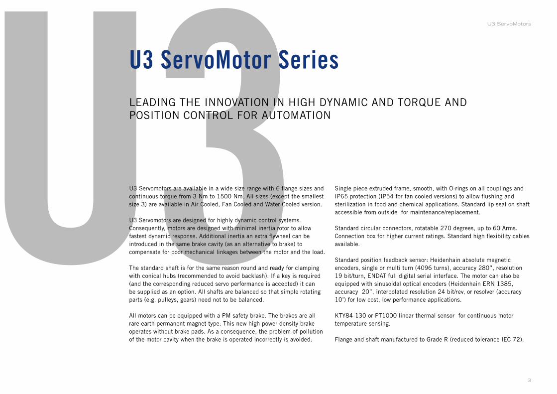
U3U3 Servomotors are available in a wide size range with 6 flange sizes and
continuous torque from 3 Nm to 1500 Nm. All sizes (except the smallest
size 3) are available in Air Cooled, Fan Cooled and Water Cooled version.
U3 Servomotors are designed for highly dynamic control systems.
Consequently, motors are designed with minimal inertia rotor to allow
fastest dynamic response. Additional inertia an extra flywheel can be
introduced in the same brake cavity (as an alternative to brake) to
compensate for poor mechanical linkages between the motor and the load.
The standard shaft is for the same reason round and ready for clamping
with conical hubs (recommended to avoid backlash). If a key is required
(and the corresponding reduced servo performance is accepted) it can
be supplied as an option. All shafts are balanced so that simple rotating
parts (e.g. pulleys, gears) need not to be balanced.
All motors can be equipped with a PM safety brake. The brakes are all
rare earth permanent magnet type. This new high power density brake
operates without brake pads. As a consequence, the problem of pollution
of the motor cavity when the brake is operated incorrectly is avoided.
LEADING THE INNOVATION IN HIGH DYNAMIC AND TORQUE AND
POSITION CONTROL FOR AUTOMATION
U3 ServoMotor Series
Single piece extruded frame, smooth, with O-rings on all couplings and
IP65 protection (IP54 for fan cooled versions) to allow flushing and
sterilization in food and chemical applications. Standard lip seal on shaft
accessible from outside for maintenance/replacement.
Standard circular connectors, rotatable 270 degrees, up to 60 Arms.
Connection box for higher current ratings. Standard high flexibility cables
available.
Standard position feedback sensor: Heidenhain absolute magnetic
encoders, single or multi turn (4096 turns), accuracy 280”, resolution
19 bit/turn, ENDAT full digital serial interface. The motor can also be
equipped with sinusoidal optical encoders (Heidenhain ERN 1385,
accuracy 20”, interpolated resolution 24 bit/rev, or resolver (accuracy
10’) for low cost, low performance applications.
KTY84-130 or PT1000 linear thermal sensor for continuous motor
temperature sensing.
Flange and shaft manufactured to Grade R (reduced tolerance IEC 72).
3
U3 ServoMotors
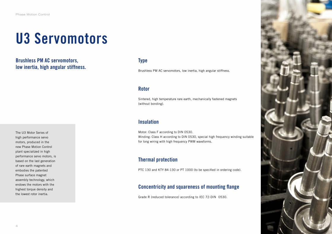
Type
Brushless PM AC servomotors, low inertia, high angular stiffness.
Rotor
Sintered, high temperature rare earth, mechanically fastened magnets
(without bonding).
Insulation
Motor: Class F according to DIN 0530.
Winding: Class H according to DIN 0530, special high frequency winding suitable
for long wiring with high frequency PWM waveforms.
Thermal protection
PTC 130 and KTY 84-130 or PT 1000 (to be specified in ordering code).
Concentricity and squareness of mounting flange
Grade R (reduced tolerance) according to IEC 72-DIN 0530.
The U3 Motor Series of
high performance servo
motors, produced in the
new Phase Motion Control
plant specialized in high
performance servo motors, is
based on the last generation
of rare earth magnets and
embodies the patented
Phase surface magnet
assembly technology, which
endows the motors with the
highest torque density and
the lowest rotor inertia.
Brushless PM AC servomotors,low inertia, high angular stiffness.
U3 Servomotors
Phase Motion Control
4
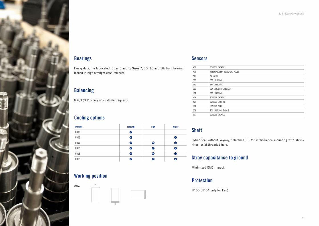
Bearings
Heavy duty, life lubricated; Sizes 3 and 5; Sizes 7, 10, 13 and 18: front bearing
locked in high strenght cast iron seat.
Balancing
G 6,3 (G 2,5 only on customer request).
Cooling options
Models Natural Fan Water
U303
U305
U307
U310
U313
U318
Working position
Any.
Sensors
N08 EQI 1331 ENDAT 01
R09 TS2640N101E64 RESOLVER 2 POLES
Z00 No sensor
C00 ECN 1313 2048
S00 ERN 1385 2048
U00 EQN 1325 2048 Endat 2.2
U01 EQN 1337 2048
M06 ECI 1319 ENDAT 01
N07 EQI 1331 Endat 21
C01 ECN1325 2048
Q01 EQN 1325 2048 Endat 2.1
M07 ECI 1319 ENDAT 22
Shaft
Cylindrical without keyway, tolerance j6, for interference mounting with shrink
rings; axial threaded hole.
Stray capacitance to ground
Minimized EMC impact.
Protection
IP 65 (IP 54 only for Fan).
5
U3 ServoMotors
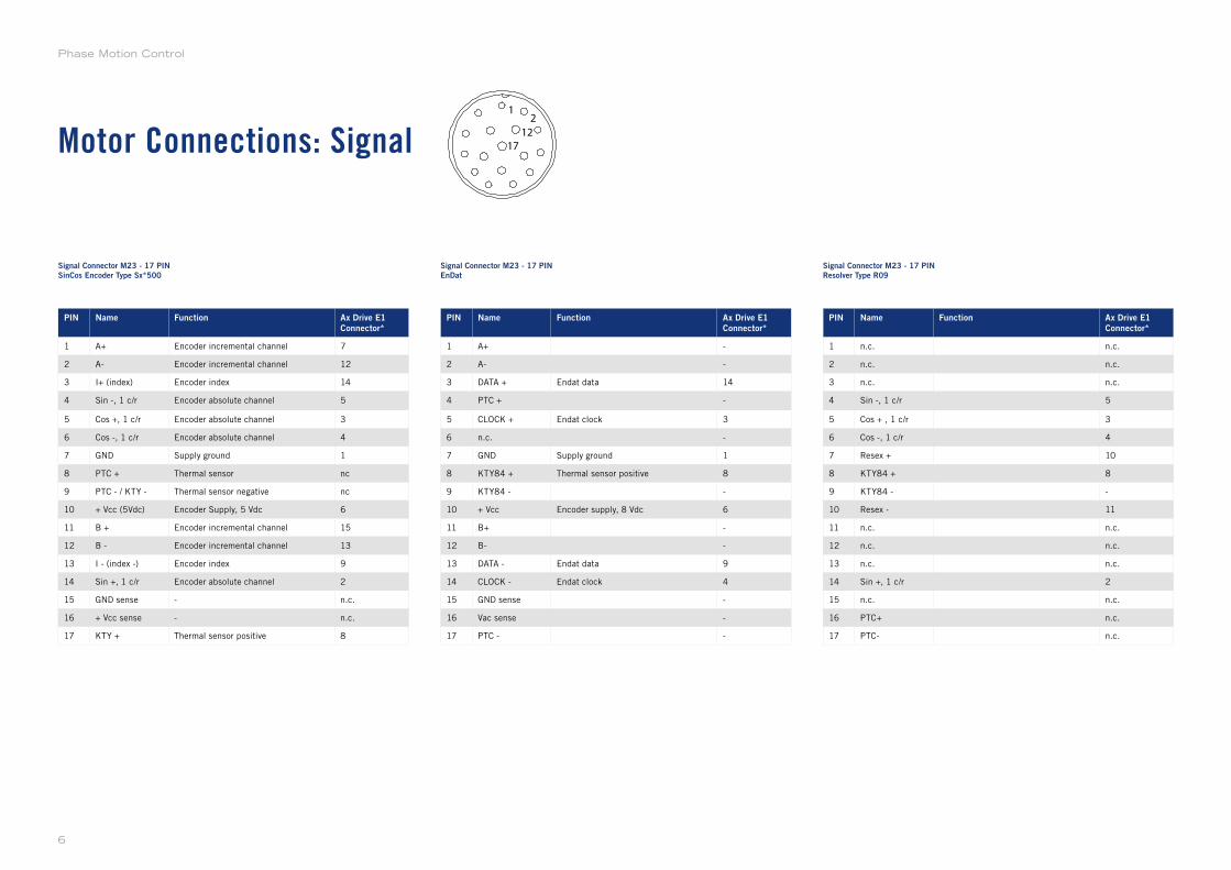
Motor Connections: Signal
PIN Name Function Ax Drive E1
Connector*
1 A+ Encoder incremental channel 7
2 A- Encoder incremental channel 12
3 I+ (index) Encoder index 14
4 Sin -, 1 c/r Encoder absolute channel 5
5 Cos +, 1 c/r Encoder absolute channel 3
6 Cos -, 1 c/r Encoder absolute channel 4
7 GND Supply ground 1
8 PTC + Thermal sensor nc
9 PTC - / KTY - Thermal sensor negative nc
10 + Vcc (5Vdc) Encoder Supply, 5 Vdc 6
11 B + Encoder incremental channel 15
12 B - Encoder incremental channel 13
13 I - (index -) Encoder index 9
14 Sin +, 1 c/r Encoder absolute channel 2
15 GND sense - n.c.
16 + Vcc sense - n.c.
17 KTY + Thermal sensor positive 8
PIN Name Function Ax Drive E1
Connector*
1 A+ -
2 A- -
3 DATA + Endat data 14
4 PTC + -
5 CLOCK + Endat clock 3
6 n.c. -
7 GND Supply ground 1
8 KTY84 + Thermal sensor positive 8
9 KTY84 - -
10 + Vcc Encoder supply, 8 Vdc 6
11 B+ -
12 B- -
13 DATA - Endat data 9
14 CLOCK - Endat clock 4
15 GND sense -
16 Vac sense -
17 PTC - -
PIN Name Function Ax Drive E1
Connector*
1 n.c. n.c.
2 n.c. n.c.
3 n.c. n.c.
4 Sin -, 1 c/r 5
5 Cos + , 1 c/r 3
6 Cos -, 1 c/r 4
7 Resex + 10
8 KTY84 + 8
9 KTY84 - -
10 Resex - 11
11 n.c. n.c.
12 n.c. n.c.
13 n.c. n.c.
14 Sin +, 1 c/r 2
15 n.c. n.c.
16 PTC+ n.c.
17 PTC- n.c.
Signal Connector M23 - 17 PIN
SinCos Encoder Type Sx*500
Signal Connector M23 - 17 PIN
EnDat
Signal Connector M23 - 17 PIN
Resolver Type R09
12
12
17
Phase Motion Control
6
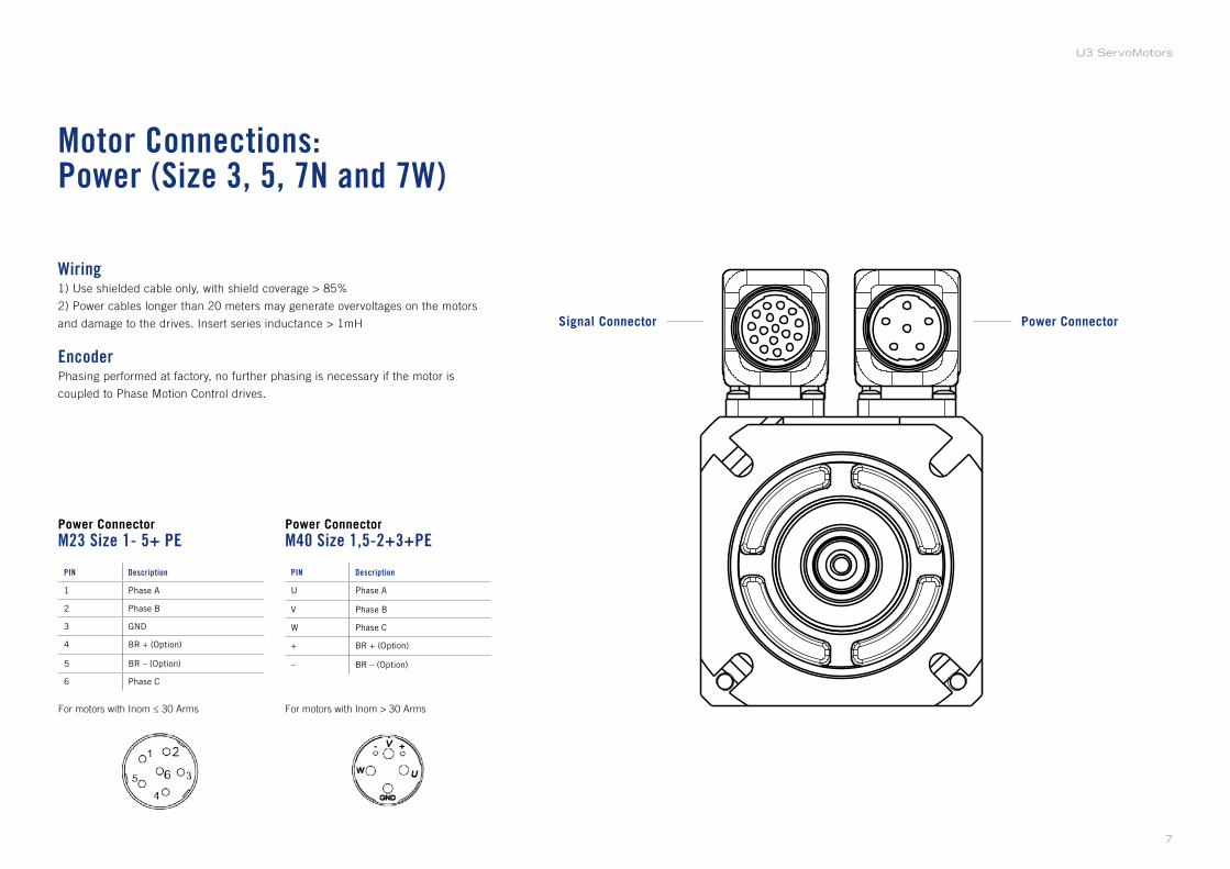
Motor Connections:Power (Size 3, 5, 7N and 7W)
Power Connector
M23 Size 1- 5+ PEPower Connector
M40 Size 1,5-2+3+PE
Power ConnectorSignal Connector
PIN Description
1 Phase A
2 Phase B
3 GND
4 BR + (Option)
5 BR – (Option)
6 Phase C
PIN Description
U Phase A
V Phase B
W Phase C
+ BR + (Option)
– BR – (Option)
For motors with Inom > 30 ArmsFor motors with Inom ≤ 30 Arms
Wiring1) Use shielded cable only, with shield coverage > 85%
2) Power cables longer than 20 meters may generate overvoltages on the motors
and damage to the drives. Insert series inductance > 1mH
EncoderPhasing performed at factory, no further phasing is necessary if the motor is
coupled to Phase Motion Control drives.
7
U3 ServoMotors
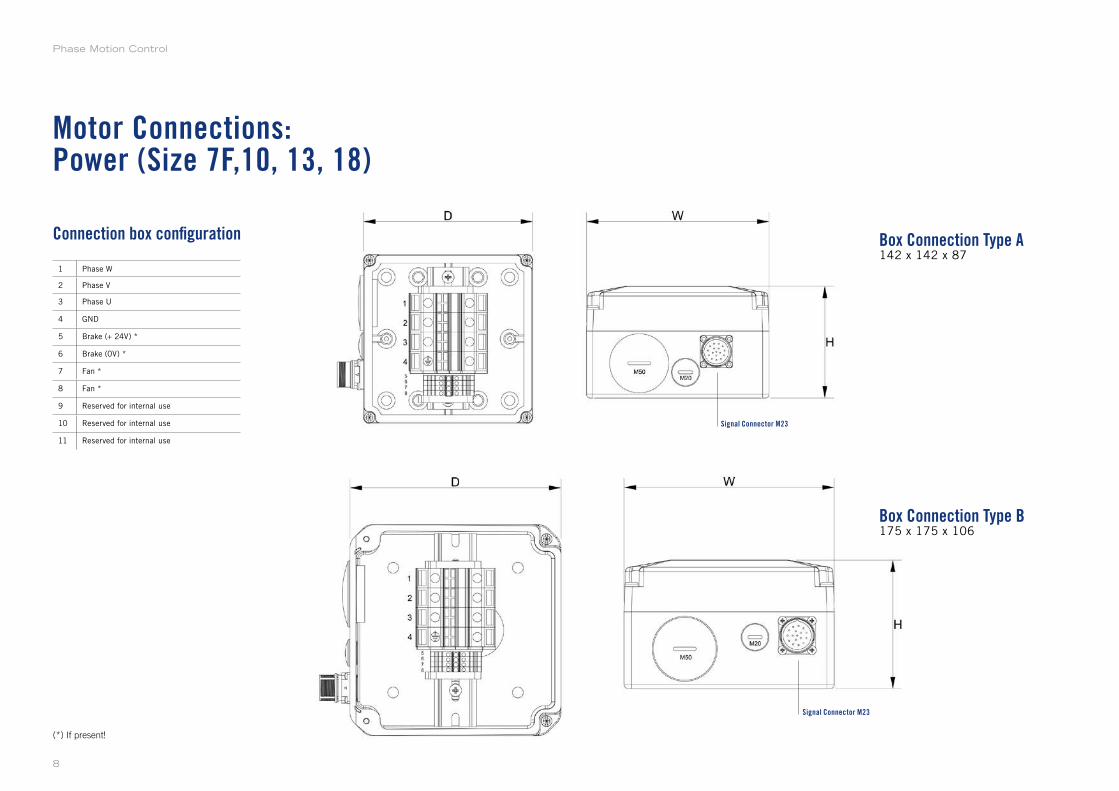
Motor Connections:Power (Size 7F,10, 13, 18)
(*) If present!
1 Phase W
2 Phase V
3 Phase U
4 GND
5 Brake (+ 24V) *
6 Brake (0V) *
7 Fan *
8 Fan *
9 Reserved for internal use
10 Reserved for internal use
11 Reserved for internal use
Connection box configuration Box Connection Type A142 x 142 x 87
Box Connection Type B175 x 175 x 106
Signal Connector M23
Signal Connector M23
Phase Motion Control
8
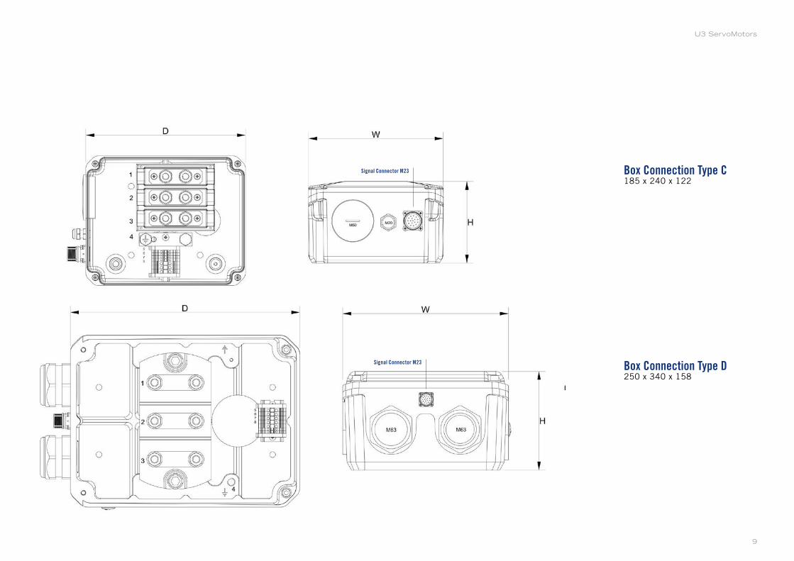
Box Connection Type C185 x 240 x 122
Box Connection Type D250 x 340 x 158
Signal Connector M23
Signal Connector M23
9
U3 ServoMotors
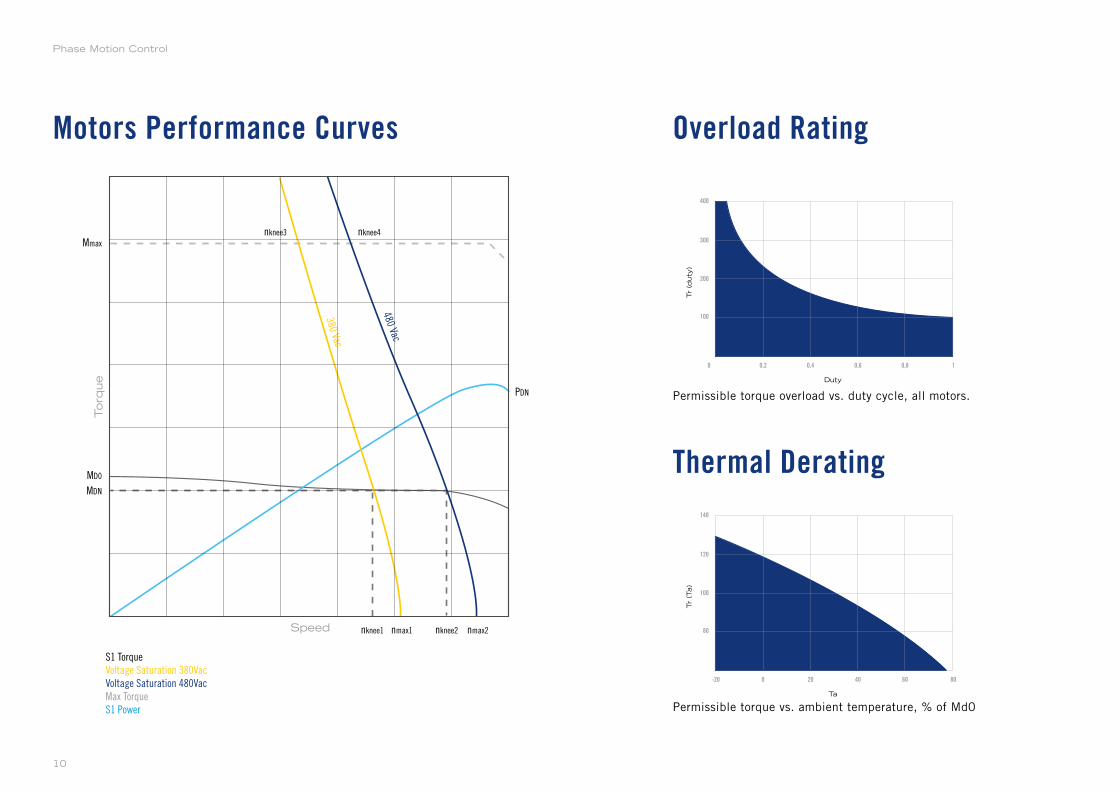
Motors Performance Curves Overload Rating
Thermal Derating
Torq
ue
Speed
Mmax
MD0
PDN
MDN
nknee1 nknee2
nknee3
380 Vac
480 Vac
nknee4
nmax1 nmax2
S1 Torque
Voltage Saturation 380Vac
Voltage Saturation 480Vac
Max Torque
S1 Power
0
Duty
Tr
(duty
)
0,2
100
200
300
400
0,6 0,8 10,4
0
TaTr
(Ta)
80
100
120
140
40 60 8020-20
Permissible torque vs. ambient temperature, % of Md0
Permissible torque overload vs. duty cycle, all motors.
Phase Motion Control
10
U303 Models
U303N
Supported Models
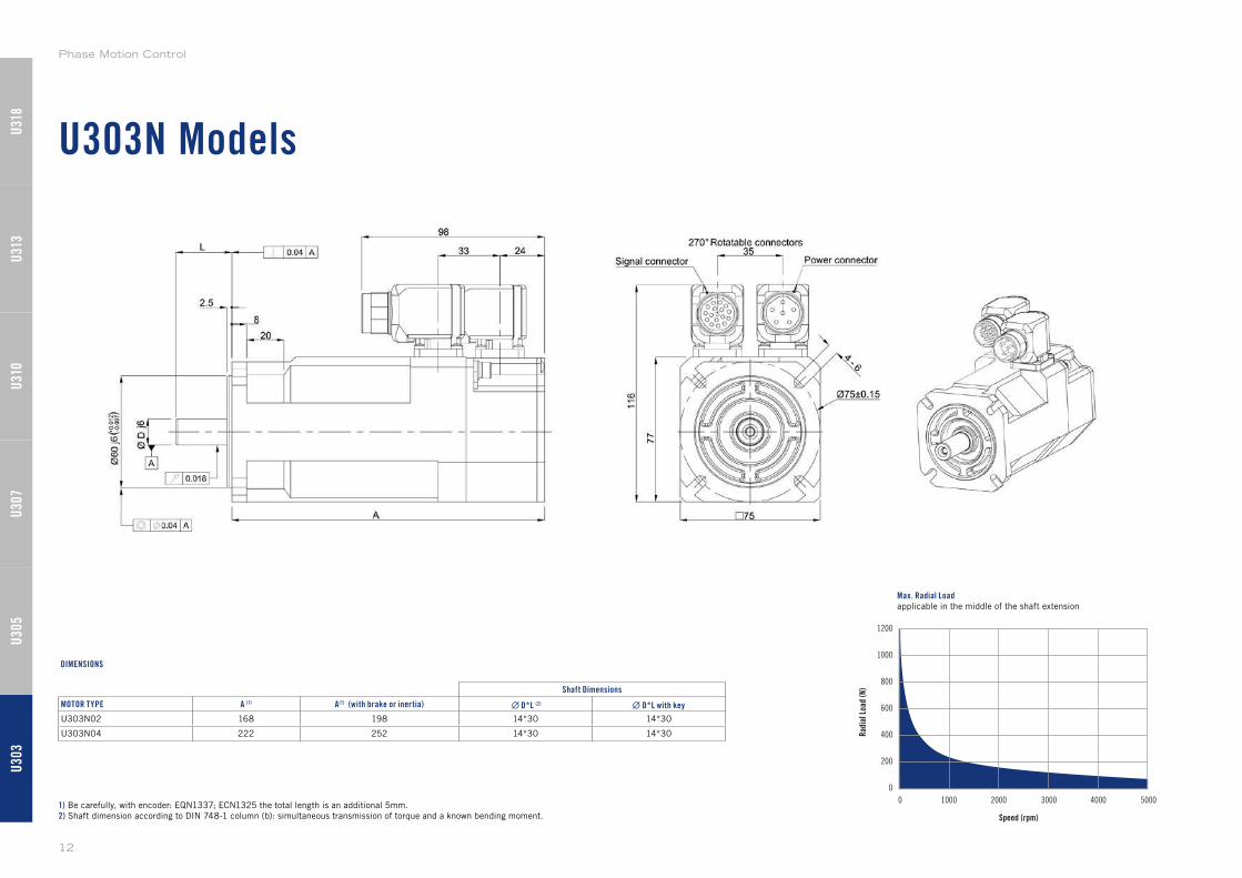
U303N Models
Shaft Dimensions
MOTOR TYPE A (1) A(1) (with brake or inertia) ∙ D*L (2) ∙ D*L with key
U303N02 168 198 14*30 14*30
U303N04 222 252 14*30 14*30
1) Be carefully, with encoder: EQN1337; ECN1325 the total length is an additional 5mm.
2) Shaft dimension according to DIN 748-1 column (b): simultaneous transmission of torque and a known bending moment.
DIMENSIONS
Speed (rpm)
1200
1000
800
600
400
200
0
0 1000 2000 3000 4000 5000
Rad
ial L
oad
(N)
Max. Radial Loadapplicable in the middle of the shaft extension
U30
3U
305
U31
0U
307
U31
3U
318
Phase Motion Control
12
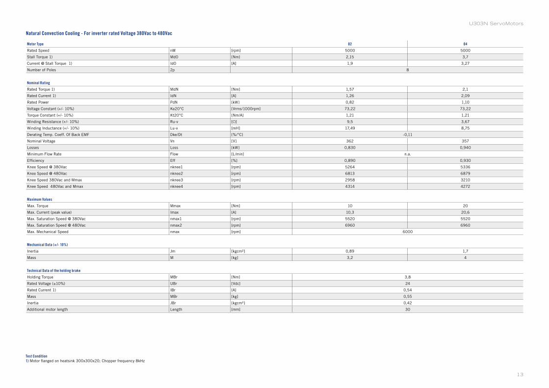
Motor Type 02 04
Rated Speed nM [rpm] 5000 5000
Stall Torque 1) Md0 [Nm] 2,15 3,7
Current @ Stall Torque 1) Id0 [A] 1,9 3,27
Number of Poles 2p 8
Nominal Rating
Rated Torque 1) MdN [Nm] 1,57 2,1
Rated Current 1) IdN [A] 1,26 2,09
Rated Power PdN [kW] 0,82 1,10
Voltage Constant (+/- 10%) Ke20°C [Vrms/1000rpm] 73,22 73,22
Torque Constant (+/- 10%) Kt20°C [Nm/A] 1,21 1,21
Winding Resistance (+/- 10%) Ru-v [Ω] 9,5 3,67
Winding Inductance (+/- 10%) Lu-v [mH] 17,49 8,75
Derating Temp. Coeff. Of Back EMF Dke/Dt [%/°C] -0,11
Nominal Voltage Vn [V] 362 357
Losses Loss [kW] 0,830 0,940
Minimum Flow Rate Flow [L/min] n.a.
Efficiency Eff [%] 0,890 0,930
Knee Speed @ 380Vac nknee1 [rpm] 5264 5336
Knee Speed @ 480Vac nknee2 [rpm] 6813 6879
Knee Speed 380Vac and Mmax nknee3 [rpm] 2958 3210
Knee Speed 480Vac and Mmax nknee4 [rpm] 4314 4272
Maximum Values
Max. Torque Mmax [Nm] 10 20
Max. Current (peak value) Imax [A] 10,3 20,6
Max. Saturation Speed @ 380Vac nmax1 [rpm] 5520 5520
Max. Saturation Speed @ 480Vac nmax2 [rpm] 6960 6960
Max. Mechanical Speed nmax [rpm] 6000
Mechanical Data (+/- 10%)
Inertia Jm [kgcm²] 0,89 1,7
Mass M [kg] 3,2 4
Technical Data of the holding brake
Holding Torque MBr [Nm] 3,8
Rated Voltage (±10%) UBr [Vdc] 24
Rated Current 1) IBr [A] 0,54
Mass MBr [kg] 0,55
Inertia JBr [kgcm²] 0,42
Additional motor length Length [mm] 30
Test Condition1) Motor flanged on heatsink 300x300x20; Chopper frequency 8kHz
Natural Convection Cooling - For inverter rated Voltage 380Vac to 480Vac
13
U303N ServoMotors
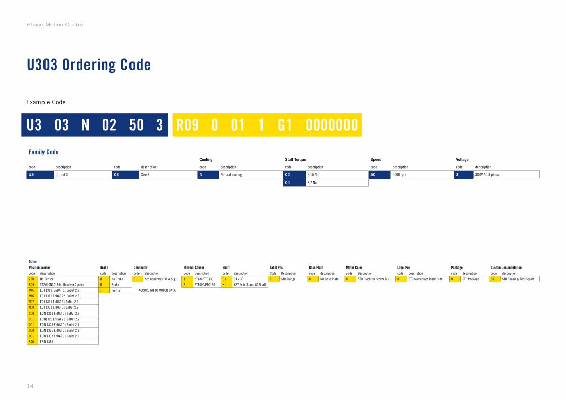
U303 Ordering Code
Example Code
Family CodeCooling Stall Torque Speed Voltage
code description code description code description code description code description code description
U3 Ultract 3 03 Size 3 N Natural cooling 02 2,15 Nm 50 5000 rpm 3 380V AC 3 phase
04 3,7 Nm
Option
Position Sensor Brake Connector Thermal Sensor Shaft Label Pos Base Plate Motor Color Label Pos Package Custom Documentation
code description code description code description Code Description code description Code Description code description code Description code description code description code description
Z00 No Sensor 0 No Brake 01 Std Coninvers PW & Sig 1 KTY84/PTC130 G1 14 x 30 0 STD Flange 0 NO Base Plate 0 STD Black rear cover Blu 0 STD Nameplate Right side 0 STD Package 00 STD Phasing/ Test report
R09 TS2640N101E64 Resolver 2 poles B Brake 2 PT1000/PTC130 K1 KEY 5x5x16 and G1Shaft
M06 ECI 1319 EnDAT 01 EnDat 2.2 J Inertia ACCORDING TO MOTOR DATA
M07 ECI 1319 EnDAT 22 EnDat 2.2
N07 EQI 1331 EnDAT 21 EnDat 2.2
N08 EQI 1331 EnDAT 01 EnDat 2.2
C00 ECN 1313 EnDAT 01 EnDat 2.2
C01 ECN1325 EnDAT 22 EnDat 2.2
Q01 EQN 1325 EnDAT 01 Endat 2.1
U00 EQN 1325 EnDAT 01 Endat 2.2
U01 EQN 1337 EnDAT 01 Endat 2.2
S00 ERN 1385
U3 03 N 02 50 3 R09 0 01 1 G1 0000000
Phase Motion Control
14

U305 Models
U305N
U305W
Supported Models
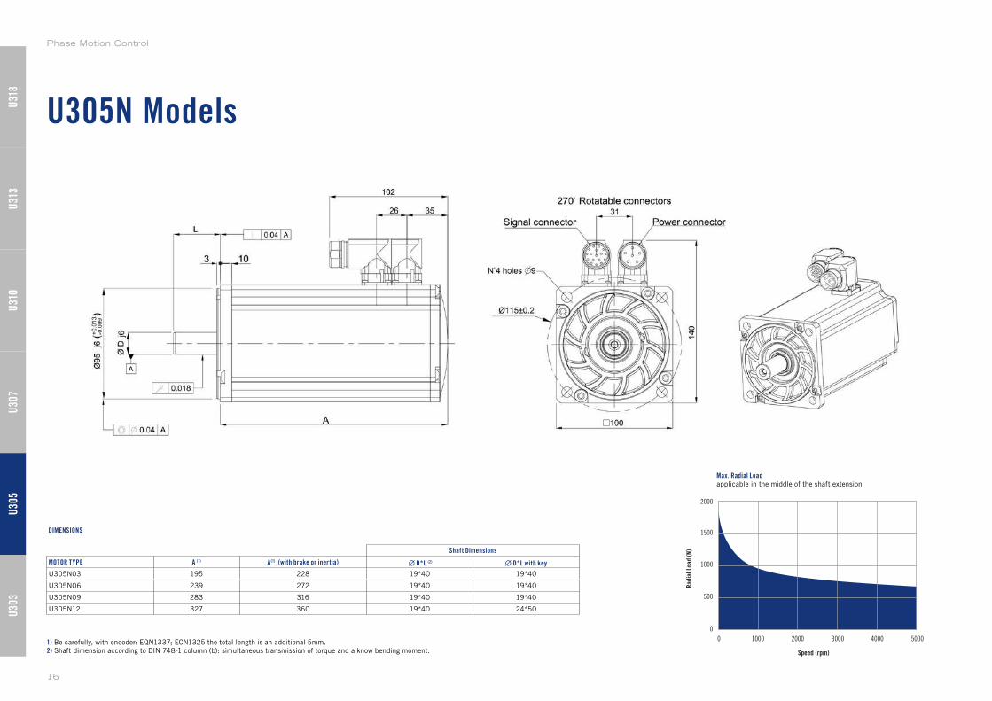
U305N Models
1) Be carefully, with encoder: EQN1337; ECN1325 the total length is an additional 5mm.
2) Shaft dimension according to DIN 748-1 column (b): simultaneous transmission of torque and a know bending moment. Speed (rpm)
2000
1500
1000
500
0
0 1000 2000 3000 4000 5000
Rad
ial L
oad
(N)
Max. Radial Loadapplicable in the middle of the shaft extension
Shaft Dimensions
MOTOR TYPE A (1) A(1) (with brake or inertia) ∙ D*L (2) ∙ D*L with key
U305N03 195 228 19*40 19*40
U305N06 239 272 19*40 19*40
U305N09 283 316 19*40 19*40
U305N12 327 360 19*40 24*50
DIMENSIONS
U30
3U
305
U31
0U
307
U31
3U
318
Phase Motion Control
16
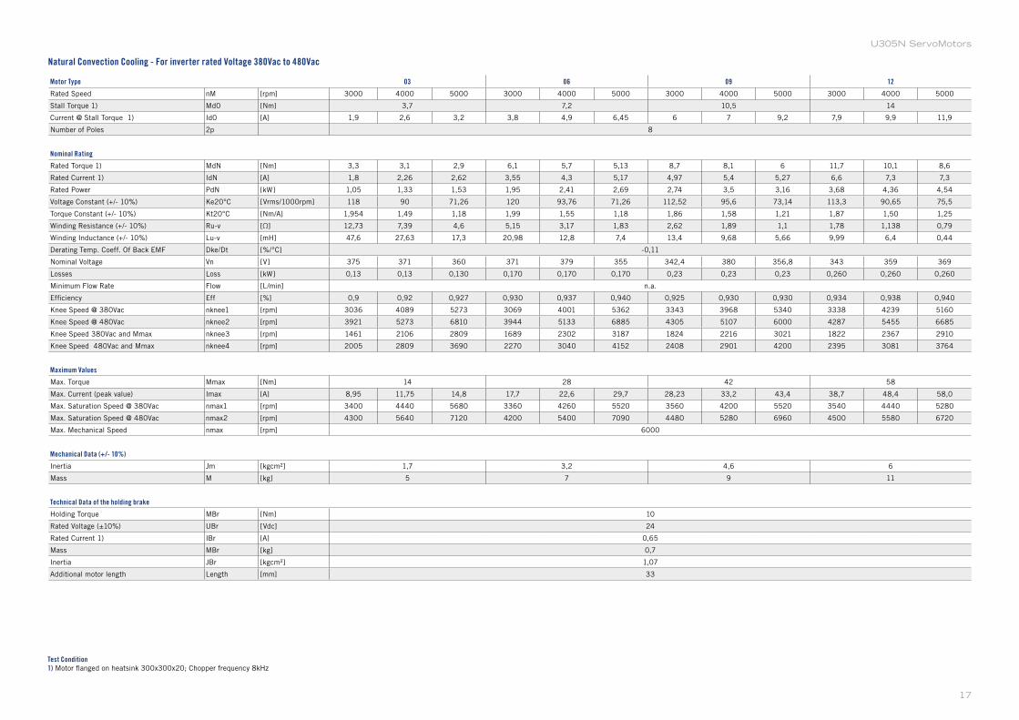
U305N ServoMotors
Motor Type 03 06 09 12
Rated Speed nM [rpm] 3000 4000 5000 3000 4000 5000 3000 4000 5000 3000 4000 5000
Stall Torque 1) Md0 [Nm] 3,7 7,2 10,5 14
Current @ Stall Torque 1) Id0 [A] 1,9 2,6 3,2 3,8 4,9 6,45 6 7 9,2 7,9 9,9 11,9
Number of Poles 2p 8
Nominal Rating
Rated Torque 1) MdN [Nm] 3,3 3,1 2,9 6,1 5,7 5,13 8,7 8,1 6 11,7 10,1 8,6
Rated Current 1) IdN [A] 1,8 2,26 2,62 3,55 4,3 5,17 4,97 5,4 5,27 6,6 7,3 7,3
Rated Power PdN [kW] 1,05 1,33 1,53 1,95 2,41 2,69 2,74 3,5 3,16 3,68 4,36 4,54
Voltage Constant (+/- 10%) Ke20°C [Vrms/1000rpm] 118 90 71,26 120 93,76 71,26 112,52 95,6 73,14 113,3 90,65 75,5
Torque Constant (+/- 10%) Kt20°C [Nm/A] 1,954 1,49 1,18 1,99 1,55 1,18 1,86 1,58 1,21 1,87 1,50 1,25
Winding Resistance (+/- 10%) Ru-v [Ω] 12,73 7,39 4,6 5,15 3,17 1,83 2,62 1,89 1,1 1,78 1,138 0,79
Winding Inductance (+/- 10%) Lu-v [mH] 47,6 27,63 17,3 20,98 12,8 7,4 13,4 9,68 5,66 9,99 6,4 0,44
Derating Temp. Coeff. Of Back EMF Dke/Dt [%/°C] -0,11
Nominal Voltage Vn [V] 375 371 360 371 379 355 342,4 380 356,8 343 359 369
Losses Loss [kW] 0,13 0,13 0,130 0,170 0,170 0,170 0,23 0,23 0,23 0,260 0,260 0,260
Minimum Flow Rate Flow [L/min] n.a.
Efficiency Eff [%] 0,9 0,92 0,927 0,930 0,937 0,940 0,925 0,930 0,930 0,934 0,938 0,940
Knee Speed @ 380Vac nknee1 [rpm] 3036 4089 5273 3069 4001 5362 3343 3968 5340 3338 4239 5160
Knee Speed @ 480Vac nknee2 [rpm] 3921 5273 6810 3944 5133 6885 4305 5107 6000 4287 5455 6685
Knee Speed 380Vac and Mmax nknee3 [rpm] 1461 2106 2809 1689 2302 3187 1824 2216 3021 1822 2367 2910
Knee Speed 480Vac and Mmax nknee4 [rpm] 2005 2809 3690 2270 3040 4152 2408 2901 4200 2395 3081 3764
Maximum Values
Max. Torque Mmax [Nm] 14 28 42 58
Max. Current (peak value) Imax [A] 8,95 11,75 14,8 17,7 22,6 29,7 28,23 33,2 43,4 38,7 48,4 58,0
Max. Saturation Speed @ 380Vac nmax1 [rpm] 3400 4440 5680 3360 4260 5520 3560 4200 5520 3540 4440 5280
Max. Saturation Speed @ 480Vac nmax2 [rpm] 4300 5640 7120 4200 5400 7090 4480 5280 6960 4500 5580 6720
Max. Mechanical Speed nmax [rpm] 6000
Mechanical Data (+/- 10%)
Inertia Jm [kgcm²] 1,7 3,2 4,6 6
Mass M [kg] 5 7 9 11
Technical Data of the holding brake
Holding Torque MBr [Nm] 10
Rated Voltage (±10%) UBr [Vdc] 24
Rated Current 1) IBr [A] 0,65
Mass MBr [kg] 0,7
Inertia JBr [kgcm²] 1,07
Additional motor length Length [mm] 33
Test Condition1) Motor flanged on heatsink 300x300x20; Chopper frequency 8kHz
Natural Convection Cooling - For inverter rated Voltage 380Vac to 480Vac
17
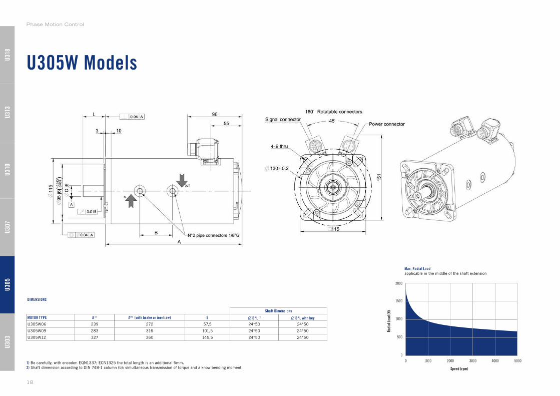
U305W Models
Speed (rpm)
2000
1500
1000
500
0
0 1000 2000 3000 4000 5000
Rad
ial L
oad
(N)
Max. Radial Loadapplicable in the middle of the shaft extension
1) Be carefully, with encoder: EQN1337; ECN1325 the total length is an additional 5mm.
2) Shaft dimension according to DIN 748-1 column (b): simultaneous transmission of torque and a know bending moment.
Shaft Dimensions
MOTOR TYPE A (1) A(1) (with brake or inertiaw) B ∙ D*L (2) ∙ D*L with key
U305W06 239 272 57,5 24*50 24*50
U305W09 283 316 101,5 24*50 24*50
U305W12 327 360 145,5 24*50 24*50
DIMENSIONS
U30
3U
305
U31
0U
307
U31
3U
318
Phase Motion Control
18
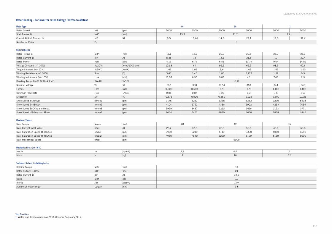
Motor Type 06 09 12
Rated Speed nM [rpm] 3000 5000 3000 5000 3000 5000
Stall Torque 1) Md0 [Nm] 13,3 21,2 29,1
Current @ Stall Torque 1) Id0 [A] 8,5 13,46 14,3 22,1 19,3 31,4
Number of Poles 2p 8
Nominal Rating
Rated Torque 1) MdN [Nm] 13,1 12,9 20,9 20,6 28,7 28,3
Rated Current 1) IdN [A] 8,35 13 14,1 21,5 19 30,4
Rated Power PdN [kW] 4,13 6,76 6,58 10,79 9,04 14,82
Voltage Constant (+/- 10%) Ke20°C [Vrms/1000rpm] 102,3 64 96,6 62,5 98,5 60,6
Torque Constant (+/- 10%) Kt20°C [Nm/A] 1,69 1,06 1,6 1,03 1,63 1,00
Winding Resistance (+/- 10%) Ru-v [Ω] 3,66 1,45 1,86 0,777 1,32 0,5
Winding Inductance (+/- 10%) Lu-v [mH] 16,53 6,55 9,83 4,1 7,66 2,9
Derating Temp. Coeff. Of Back EMF Dke/Dt [%/°C] -0,11
Nominal Voltage Vn [V] 357 358 337,4 350 344 340
Losses Loss [kW] 0,600 0,600 0,9 0,9 1,100 1,100
Minimum Flow Rate Flow [L/min] 0,85 0,87 1,23 1,3 1,6 1,63
Efficiency Eff [%] 0,875 0,920 0,860 0,925 0,890 0,925
Knee Speed @ 380Vac nknee1 [rpm] 3176 5257 3368 5383 3290 5538
Knee Speed @ 480Vac nknee2 [rpm] 4104 6752 4338 6902 4233 7095
Knee Speed 380Vac and Mmax nknee3 [rpm] 1999 3437 2210 3616 2193 3771
Knee Speed 480Vac and Mmax nknee4 [rpm] 2644 4452 2889 4660 2858 4846
Maximum Values
Max. Torque Mmax [Nm] 28 42 56
Max. Current (peak value) Imax [A] 20,7 32,8 32,8 50,8 43,0 69,8
Max. Saturation Speed @ 380Vac nmax1 [rpm] 3960 6240 4140 6300 4050 6640
Max. Saturation Speed @ 480Vac nmax2 [rpm] 4980 7840 5220 8190 5130 8000
Max. Mechanical Speed nmax [rpm] 6000
Mechanical Data (+/- 10%)
Inertia Jm [kgcm²] 3,2 4,6 6
Mass M [kg] 8 10 12
Technical Data of the holding brake
Holding Torque MBr [Nm] 10
Rated Voltage (±10%) UBr [Vdc] 24
Rated Current 1) IBr [A] 0,65
Mass MBr [kg] 0,7
Inertia JBr [kgcm²] 1,07
Additional motor length Length [mm] 33
Test Condition1) Water inlet temperature max 20°C; Chopper frequency 8kHz
Water Cooling - For inverter rated Voltage 380Vac to 480Vac
19
U305W ServoMotors
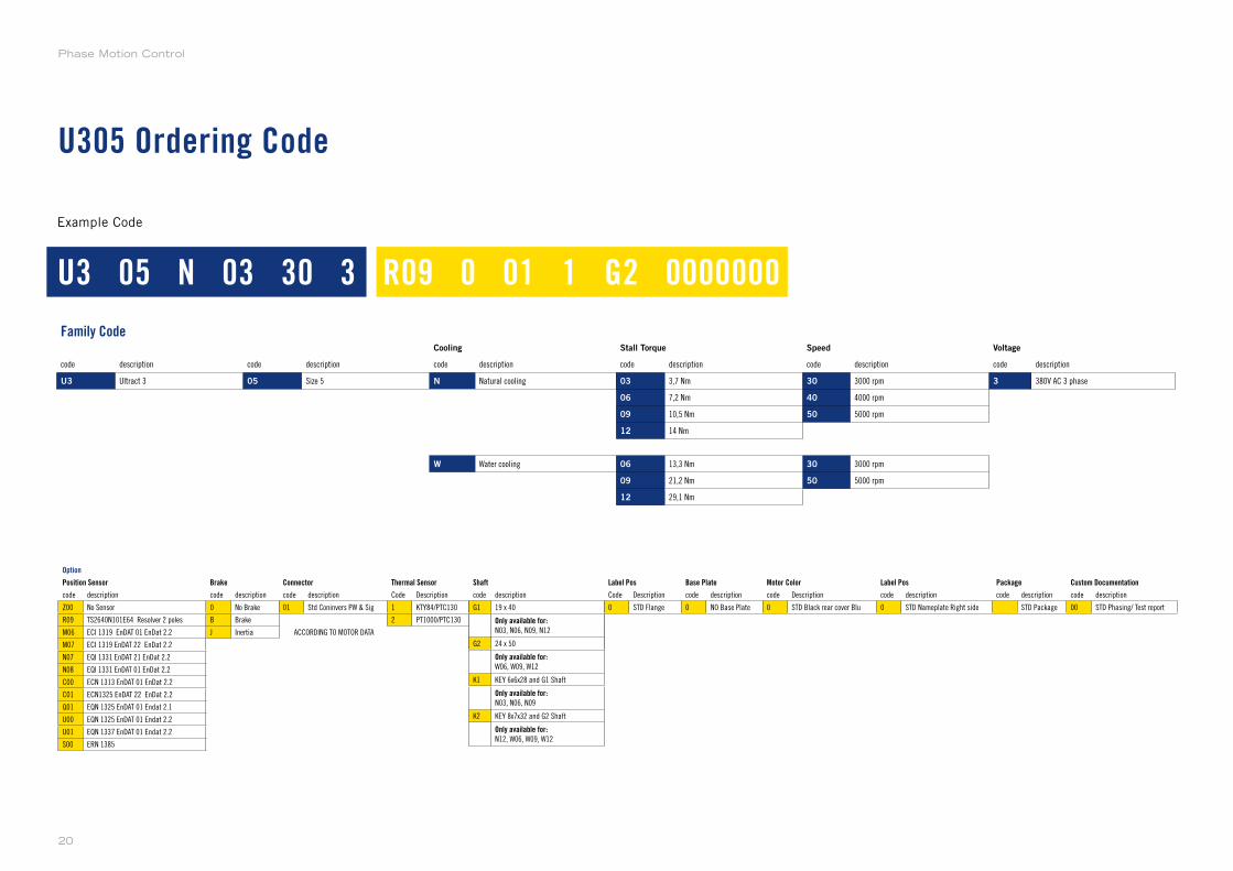
U305 Ordering Code
Family CodeCooling Stall Torque Speed Voltage
code description code description code description code description code description code description
U3 Ultract 3 05 Size 5 N Natural cooling 03 3,7 Nm 30 3000 rpm 3 380V AC 3 phase
06 7,2 Nm 40 4000 rpm
09 10,5 Nm 50 5000 rpm
12 14 Nm
W Water cooling 06 13,3 Nm 30 3000 rpm
09 21,2 Nm 50 5000 rpm
12 29,1 Nm
Option
Position Sensor Brake Connector Thermal Sensor Shaft Label Pos Base Plate Motor Color Label Pos Package Custom Documentation
code description code description code description Code Description code description Code Description code description code Description code description code description code description
Z00 No Sensor 0 No Brake 01 Std Coninvers PW & Sig 1 KTY84/PTC130 G1 19 x 40 (from U3503 to U3509) 0 STD Flange 0 NO Base Plate 0 STD Black rear cover Blu 0 STD Nameplate Right side 0 STD Package 00 STD Phasing/ Test report
R09 TS2640N101E64 Resolver 2 poles B Brake 2 PT1000/PTC130 G2 24 x 50 (for U3512)
M06 ECI 1319 EnDAT 01 EnDat 2.2 J Inertia ACCORDING TO MOTOR DATA K1 KEY 6x6x28 and G1 Shaft
M07 ECI 1319 EnDAT 22 EnDat 2.2 K2 KEY 8x7x32 and G2 Shaft
N07 EQI 1331 EnDAT 21 EnDat 2.2
N08 EQI 1331 EnDAT 01 EnDat 2.2
C00 ECN 1313 EnDAT 01 EnDat 2.2
C01 ECN1325 EnDAT 22 EnDat 2.2
Q01 EQN 1325 EnDAT 01 Endat 2.1
U00 EQN 1325 EnDAT 01 Endat 2.2
U01 EQN 1337 EnDAT 01 Endat 2.2
S00 ERN 1385
Example Code
U3 05 N 03 30 3 R09 0 01 1 G2 0000000
code description
G1 19 x 40
Only available for:N03, N06, N09, N12
G2 24 x 50
Only available for:W06, W09, W12
K1 KEY 6x6x28 and G1 Shaft
Only available for:N03, N06, N09
K2 KEY 8x7x32 and G2 Shaft
Only available for:N12, W06, W09, W12
Phase Motion Control
20

U307 Models
U307N
U307F
U307W
Supported Models
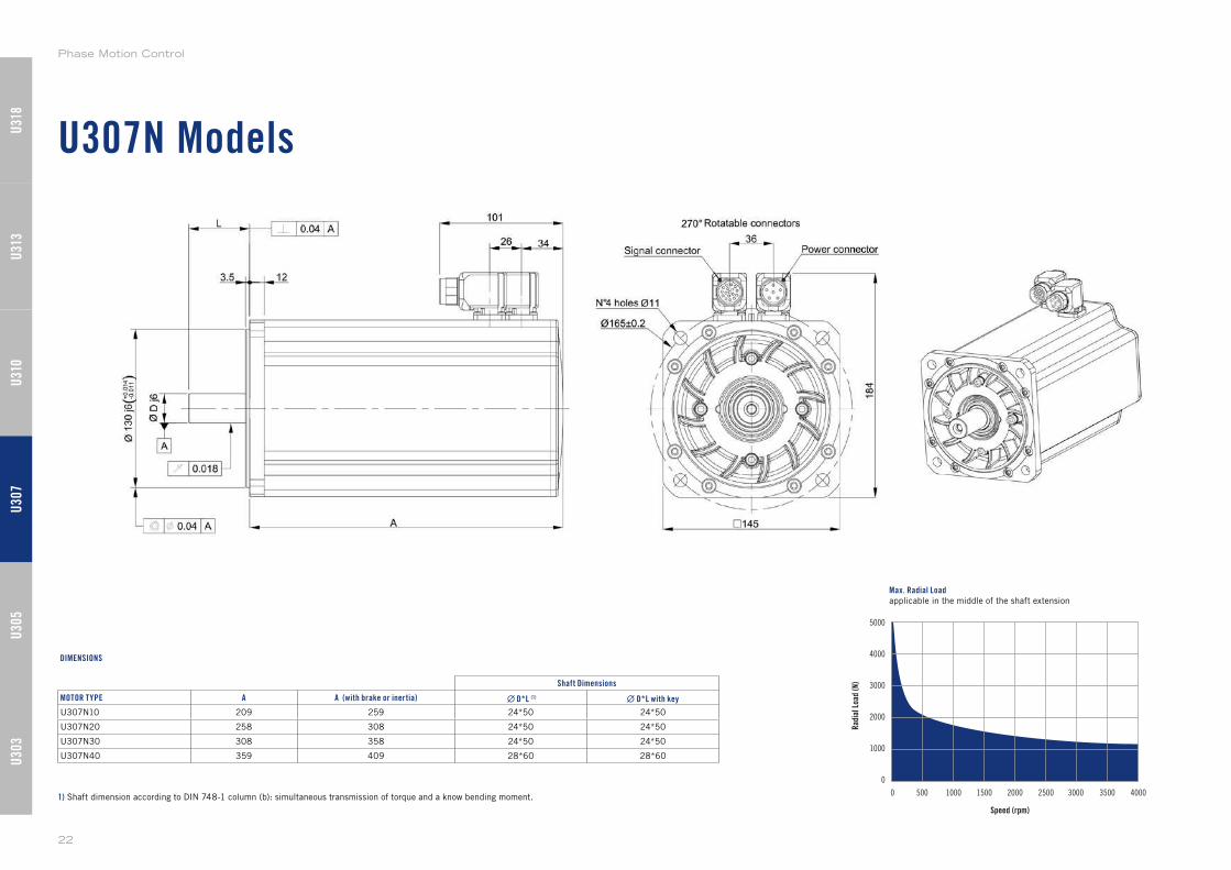
U307N Models
Speed (rpm)
5000
4000
3000
2000
1000
0
0 500 1000 1500 2000 2500 40003000 3500
Rad
ial L
oad
(N)
Max. Radial Loadapplicable in the middle of the shaft extension
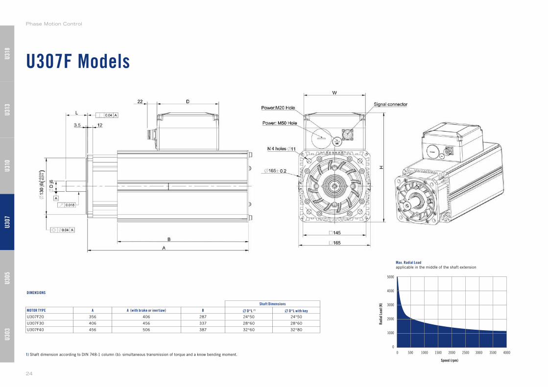
1) Shaft dimension according to DIN 748-1 column (b): simultaneous transmission of torque and a know bending moment.
Shaft Dimensions
MOTOR TYPE A A (with brake or inertia) ∙ D*L (1) ∙ D*L with key
U307N10 209 259 24*50 24*50
U307N20 258 308 24*50 24*50
U307N30 308 358 24*50 24*50
U307N40 359 409 28*60 28*60
DIMENSIONS
U30
3U
305
U31
0U
307
U31
3U
318
Phase Motion Control
22
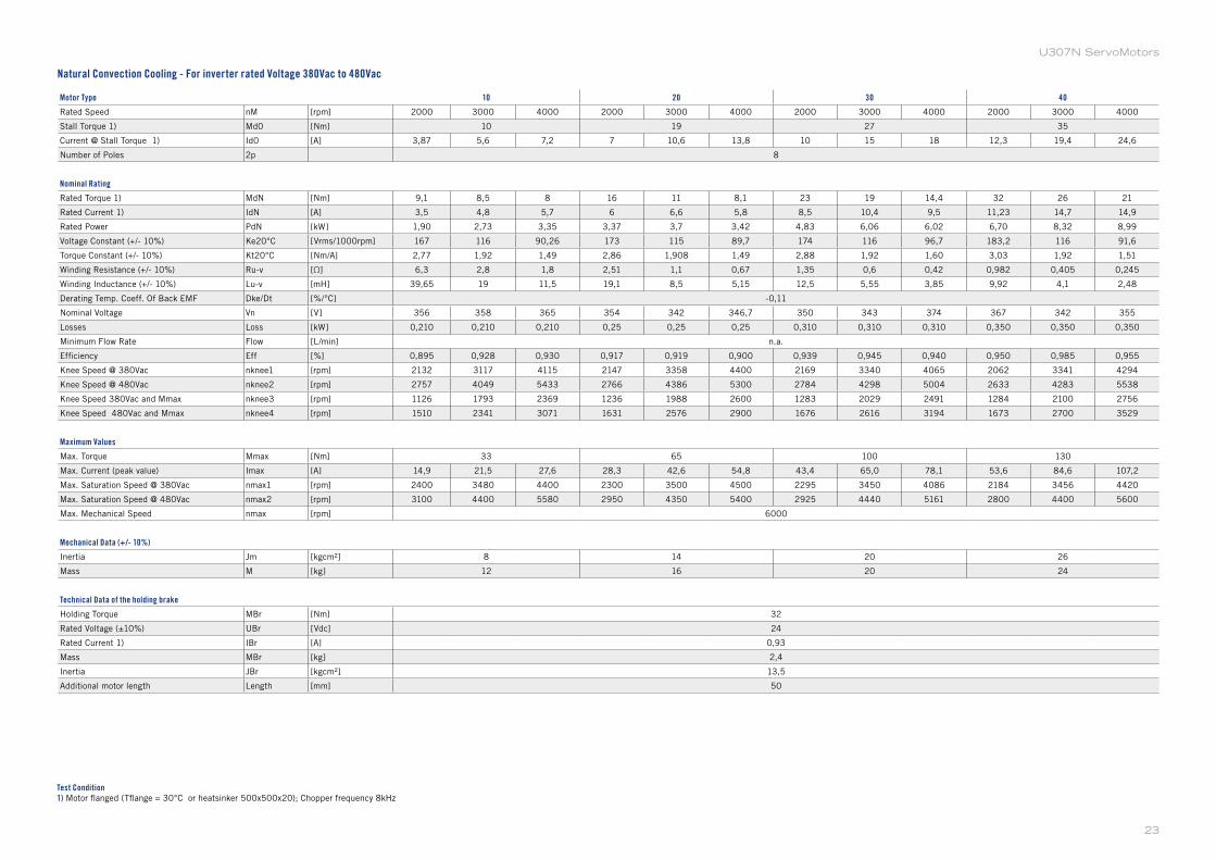
U307N ServoMotors
Motor Type 10 20 30 40
Rated Speed nM [rpm] 2000 3000 4000 2000 3000 4000 2000 3000 4000 2000 3000 4000
Stall Torque 1) Md0 [Nm] 10 19 27 35
Current @ Stall Torque 1) Id0 [A] 3,87 5,6 7,2 7 10,6 13,8 10 15 18 12,3 19,4 24,6
Number of Poles 2p 8
Nominal Rating
Rated Torque 1) MdN [Nm] 9,1 8,5 8 16 11 8,1 23 19 14,4 32 26 21
Rated Current 1) IdN [A] 3,5 4,8 5,7 6 6,6 5,8 8,5 10,4 9,5 11,23 14,7 14,9
Rated Power PdN [kW] 1,90 2,73 3,35 3,37 3,7 3,42 4,83 6,06 6,02 6,70 8,32 8,99
Voltage Constant (+/- 10%) Ke20°C [Vrms/1000rpm] 167 116 90,26 173 115 89,7 174 116 96,7 183,2 116 91,6
Torque Constant (+/- 10%) Kt20°C [Nm/A] 2,77 1,92 1,49 2,86 1,908 1,49 2,88 1,92 1,60 3,03 1,92 1,51
Winding Resistance (+/- 10%) Ru-v [Ω] 6,3 2,8 1,8 2,51 1,1 0,67 1,35 0,6 0,42 0,982 0,405 0,245
Winding Inductance (+/- 10%) Lu-v [mH] 39,65 19 11,5 19,1 8,5 5,15 12,5 5,55 3,85 9,92 4,1 2,48
Derating Temp. Coeff. Of Back EMF Dke/Dt [%/°C] -0,11
Nominal Voltage Vn [V] 356 358 365 354 342 346,7 350 343 374 367 342 355
Losses Loss [kW] 0,210 0,210 0,210 0,25 0,25 0,25 0,310 0,310 0,310 0,350 0,350 0,350
Minimum Flow Rate Flow [L/min] n.a.
Efficiency Eff [%] 0,895 0,928 0,930 0,917 0,919 0,900 0,939 0,945 0,940 0,950 0,985 0,955
Knee Speed @ 380Vac nknee1 [rpm] 2132 3117 4115 2147 3358 4400 2169 3340 4065 2062 3341 4294
Knee Speed @ 480Vac nknee2 [rpm] 2757 4049 5433 2766 4386 5300 2784 4298 5004 2633 4283 5538
Knee Speed 380Vac and Mmax nknee3 [rpm] 1126 1793 2369 1236 1988 2600 1283 2029 2491 1284 2100 2756
Knee Speed 480Vac and Mmax nknee4 [rpm] 1510 2341 3071 1631 2576 2900 1676 2616 3194 1673 2700 3529
Maximum Values
Max. Torque Mmax [Nm] 33 65 100 130
Max. Current (peak value) Imax [A] 14,9 21,5 27,6 28,3 42,6 54,8 43,4 65,0 78,1 53,6 84,6 107,2
Max. Saturation Speed @ 380Vac nmax1 [rpm] 2400 3480 4400 2300 3500 4500 2295 3450 4086 2184 3456 4420
Max. Saturation Speed @ 480Vac nmax2 [rpm] 3100 4400 5580 2950 4350 5400 2925 4440 5161 2800 4400 5600
Max. Mechanical Speed nmax [rpm] 6000
Mechanical Data (+/- 10%)
Inertia Jm [kgcm²] 8 14 20 26
Mass M [kg] 12 16 20 24
Technical Data of the holding brake
Holding Torque MBr [Nm] 32
Rated Voltage (±10%) UBr [Vdc] 24
Rated Current 1) IBr [A] 0,93
Mass MBr [kg] 2,4
Inertia JBr [kgcm²] 13,5
Additional motor length Length [mm] 50
Test Condition1) Motor flanged (Tflange = 30°C or heatsinker 500x500x20); Chopper frequency 8kHz
Natural Convection Cooling - For inverter rated Voltage 380Vac to 480Vac
23
U307F Models
Speed (rpm)
5000
4000
3000
2000
1000
0
0 500 1000 1500 2000 2500 40003000 3500
Rad
ial L
oad
(N)
Max. Radial Loadapplicable in the middle of the shaft extension
DIMENSIONS
1) Shaft dimension according to DIN 748-1 column (b): simultaneous transmission of torque and a know bending moment.
Shaft Dimensions
MOTOR TYPE A A (with brake or inertiaw) B ∙ D*L (1) ∙ D*L with key
U307F20 356 406 287 24*50 24*50
U307F30 406 456 337 28*60 28*60
U307F40 456 506 387 32*60 32*80
U30
3U
305
U31
0U
307
U31
3U
318
Phase Motion Control
24
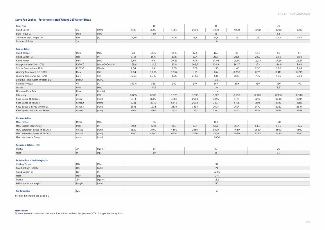
U307F ServoMotors
Motor Type 20 30 40
Rated Speed nM [rpm] 2000 3000 4000 2000 3000 4000 2000 3000 4000
Stall Torque 1) Md0 [Nm] 30 46 62
Current @ Stall Torque 1) Id0 [A] 12,45 17,2 23,8 18,5 26,5 35 25 35,7 45,6
Number of Poles 2p 8
Nominal Rating
Rated Torque 1) MdN [Nm] 28 26,5 24,5 42,5 41,6 37 57,5 55 51
Rated Current 1) IdN [A] 11,8 15,6 19,8 17,4 23,7 28,5 25,2 32,2 38,5
Rated Power PdN [kW] 5,86 8,3 10,26 9,05 13,08 15,50 12,04 17,28 21,36
Voltage Constant (+/- 10%) Ke20°C [Vrms/1000rpm] 159,6 114,9 83,8 162,7 114,9 86,17 153 114,9 89,4
Torque Constant (+/- 10%) Kt20°C [Nm/A] 2,64 1,9 1,39 2,69 1,90 1,43 2,53 1,90 1,48
Winding Resistance (+/- 10%) Ru-v [Ω] 2,04 1,058 0,554 1,2 0,6 0,338 0,73 0,411 0,249
Winding Inductance (+/- 10%) Lu-v [mH] 16,84 8,723 4,55 11,68 5,8 3,27 7,76 4,36 2,64
Derating Temp. Coeff. Of Back EMF Dke/Dt [%/°C] -0,11
Nominal Voltage Vn [V] 353,8 369 350 357 367 359 335 366 373
Losses Loss [kW] 0,6 1,0 1,3
Minimum Flow Rate Flow [L/min] n.a.
Efficiency Eff [%] 0,885 0,910 0,920 0,898 0,920 0,930 0,920 0,930 0,940
Knee Speed @ 380Vac nknee1 [rpm] 2114 3029 4288 2088 3046 4179 2223 3048 4004
Knee Speed @ 480Vac nknee2 [rpm] 2731 3910 5546 2693 3931 5425 2875 3927 5183
Knee Speed 380Vac and Mmax nknee3 [rpm] 1351 1938 2819 1334 2004 2694 1470 2020 2647
Knee Speed 480Vac and Mmax nknee4 [rpm] 1769 2509 3620 1737 2581 3452 1904 2559 3388
Maximum Values
Max. Torque Mmax [Nm] 65 100 130
Max. Current (peak value) Imax [A] 30,8 42,8 58,7 46,4 65,8 87,7 64,3 85,6 110,2
Max. Saturation Speed @ 380Vac nmax1 [rpm] 2520 3450 4800 2450 3500 4680 2650 3500 4500
Max. Saturation Speed @ 480Vac nmax2 [rpm] 3200 4380 6100 3150 4400 5880 3350 4440 5750
Max. Mechanical Speed nmax [rpm] 6000
Mechanical Data (+/- 10%)
Inertia Jm [kgcm²] 14 20 26
Mass M [kg] 19 25 31
Technical Data of the holding brake
Holding Torque MBr [Nm] 32
Rated Voltage (±10%) UBr [Vdc] 24
Rated Current 1) IBr [A] 93,00
Mass MBr [kg] 2,4
Inertia JBr [kgcm²] 13,5
Additional motor length Length [mm] 50
Box Connection type A
Test Condition1) Motor tested in horizontal position in free still air, ambient temperature 30°C; Chopper frequency 8kHz
For Box dimensions see page 8-9
Servo Fan Cooling - For inverter rated Voltage 380Vac to 480Vac
25
U307W Models
Speed (rpm)
5000
4000
3000
2000
1000
0
0 500 1000 1500 2000 2500 40003000 3500
Rad
ial L
oad
(N)
Max. Radial Loadapplicable in the middle of the shaft extension
DIMENSIONS
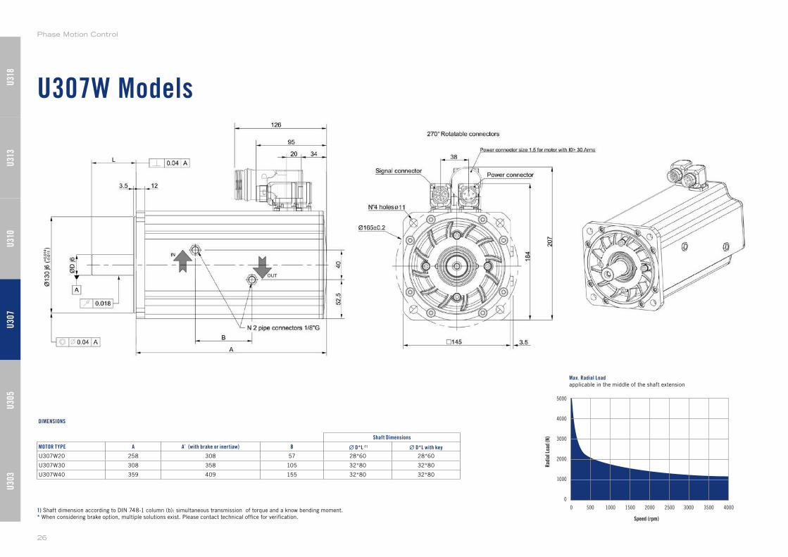
1) Shaft dimension according to DIN 748-1 column (b): simultaneous transmission of torque and a know bending moment.
* When considering brake option, multiple solutions exist. Please contact technical office for verification.
Shaft Dimensions
MOTOR TYPE A A* (with brake or inertiaw) B ∙ D*L (1) ∙ D*L with key
U307W20 258 308 57 28*60 28*60
U307W30 308 358 105 32*80 32*80
U307W40 359 409 155 32*80 32*80
U30
3U
305
U31
0U
307
U31
3U
318
Phase Motion Control
26
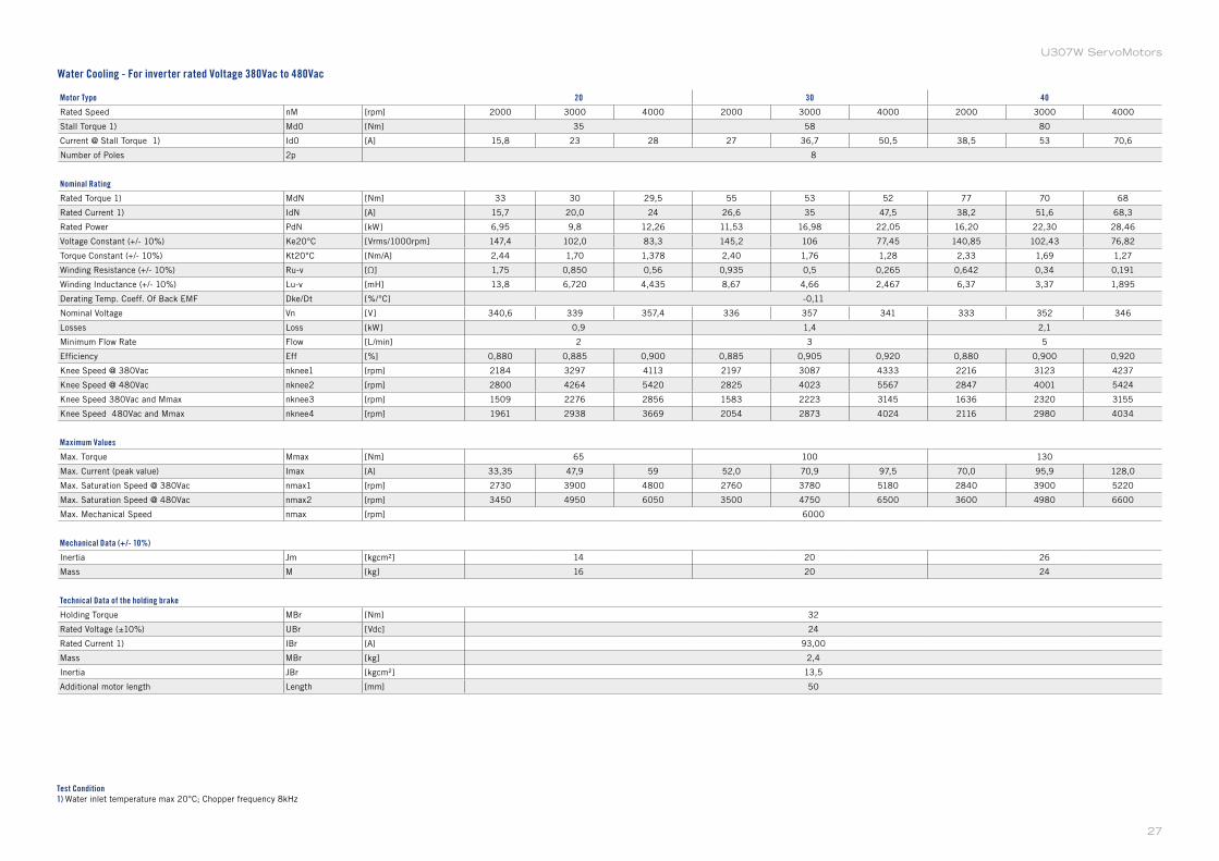
U307W ServoMotors
Motor Type 20 30 40
Rated Speed nM [rpm] 2000 3000 4000 2000 3000 4000 2000 3000 4000
Stall Torque 1) Md0 [Nm] 35 58 80
Current @ Stall Torque 1) Id0 [A] 15,8 23 28 27 36,7 50,5 38,5 53 70,6
Number of Poles 2p 8
Nominal Rating
Rated Torque 1) MdN [Nm] 33 30 29,5 55 53 52 77 70 68
Rated Current 1) IdN [A] 15,7 20,0 24 26,6 35 47,5 38,2 51,6 68,3
Rated Power PdN [kW] 6,95 9,8 12,26 11,53 16,98 22,05 16,20 22,30 28,46
Voltage Constant (+/- 10%) Ke20°C [Vrms/1000rpm] 147,4 102,0 83,3 145,2 106 77,45 140,85 102,43 76,82
Torque Constant (+/- 10%) Kt20°C [Nm/A] 2,44 1,70 1,378 2,40 1,76 1,28 2,33 1,69 1,27
Winding Resistance (+/- 10%) Ru-v [Ω] 1,75 0,850 0,56 0,935 0,5 0,265 0,642 0,34 0,191
Winding Inductance (+/- 10%) Lu-v [mH] 13,8 6,720 4,435 8,67 4,66 2,467 6,37 3,37 1,895
Derating Temp. Coeff. Of Back EMF Dke/Dt [%/°C] -0,11
Nominal Voltage Vn [V] 340,6 339 357,4 336 357 341 333 352 346
Losses Loss [kW] 0,9 1,4 2,1
Minimum Flow Rate Flow [L/min] 2 3 5
Efficiency Eff [%] 0,880 0,885 0,900 0,885 0,905 0,920 0,880 0,900 0,920
Knee Speed @ 380Vac nknee1 [rpm] 2184 3297 4113 2197 3087 4333 2216 3123 4237
Knee Speed @ 480Vac nknee2 [rpm] 2800 4264 5420 2825 4023 5567 2847 4001 5424
Knee Speed 380Vac and Mmax nknee3 [rpm] 1509 2276 2856 1583 2223 3145 1636 2320 3155
Knee Speed 480Vac and Mmax nknee4 [rpm] 1961 2938 3669 2054 2873 4024 2116 2980 4034
Maximum Values
Max. Torque Mmax [Nm] 65 100 130
Max. Current (peak value) Imax [A] 33,35 47,9 59 52,0 70,9 97,5 70,0 95,9 128,0
Max. Saturation Speed @ 380Vac nmax1 [rpm] 2730 3900 4800 2760 3780 5180 2840 3900 5220
Max. Saturation Speed @ 480Vac nmax2 [rpm] 3450 4950 6050 3500 4750 6500 3600 4980 6600
Max. Mechanical Speed nmax [rpm] 6000
Mechanical Data (+/- 10%)
Inertia Jm [kgcm²] 14 20 26
Mass M [kg] 16 20 24
Technical Data of the holding brake
Holding Torque MBr [Nm] 32
Rated Voltage (±10%) UBr [Vdc] 24
Rated Current 1) IBr [A] 93,00
Mass MBr [kg] 2,4
Inertia JBr [kgcm²] 13,5
Additional motor length Length [mm] 50
Test Condition1) Water inlet temperature max 20°C; Chopper frequency 8kHz
Water Cooling - For inverter rated Voltage 380Vac to 480Vac
27
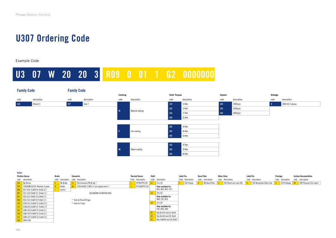
U307 Ordering Code
Example Code
Family Code Family CodeCooling Stall Torque Speed Voltage
code description code description code description code description code description code description
U3 Ultract 3 07 Size 7
N Natural cooling
10 10 Nm 20 2000rpm 3 380V AC 3 phase
20 19 Nm 30 3000rpm
30 27 Nm 40 4000rpm
40 35 Nm
F Fan cooling
20 30 Nm
30 46 Nm
40 62 Nm
W Water cooling
20 35 Nm
30 58 Nm
40 80 Nm
Option
Position Sensor Brake Connector Thermal Sensor Shaft Label Pos Base Plate Motor Color Label Pos Package Custom Documentation
code description code description code description Code Description code description Code Description code description code Description code description code description code description
Z00 No Sensor 0 No Brake 01 Std Coninvers PW & Sig (1) 1 KTY84/PTC130 G1 24 x 50 0 STD Flange 0 NO Base Plate 0 STD Black rear cover Blu 0 STD Nameplate Right side 0 STD Package 00 STD Phasing/ Test report
R09 TS2640N101E64 Resolver 2 poles B Brake A0 142x142x87.5 (M23 17 pin signal conn) (2) 2 PT1000/PTC130 G2 28 x 60
M06 ECI 1319 EnDAT 01 EnDat 2.2 J Inertia G3 32 x 60
M07 ECI 1319 EnDAT 22 EnDat 2.2 ACCORDING TO MOTOR DATA K1 Key 8x7x32 and G1 Shaft
N07 EQI 1331 EnDAT 21 EnDat 2.2 K2 Key 8x7x40 and G2 Shaft
N08 EQI 1331 EnDAT 01 EnDat 2.2 (1) Only for N and W type K3 Key 10x8x40 and G3 Shaft
C00 ECN 1313 EnDAT 01 EnDat 2.2 (2) Only for F type
C01 ECN1325 EnDAT 22 EnDat 2.2
Q01 EQN 1325 EnDAT 01 Endat 2.1
U00 EQN 1325 EnDAT 01 Endat 2.2
U01 EQN 1337 EnDAT 01 Endat 2.2
S00 ERN 1385
U3 07 W 20 20 3 R09 0 01 1 G2 0000000
code description
G1 24 x 50
Only available for:N10, N20, N30, F20
G2 28 x 60
Only available for:N40, F30, W20
G3 32 x 60
Only available for:F40, W30, W40
K1 Key 8x7x32 and G1 Shaft
K2 Key 8x7x40 and G2 Shaft
K3 Key 10x8x40 and G3 Shaft
Phase Motion Control
28

U310 Models
U310N
U310F
U310W
Supported Models
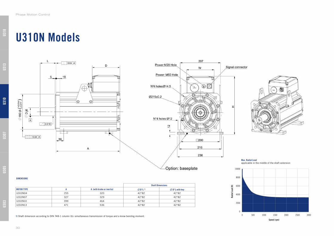
U310N Models
Speed (rpm)
10000
8000
6000
4000
2000
0
0 500 1000 1500 2000 2500 3000
Rad
ial L
oad
(N)
Max. Radial Loadapplicable in the middle of the shaft extension
1) Shaft dimension according to DIN 748-1 column (b): simultaneous transmission of torque and a know bending moment.
Shaft Dimensions
MOTOR TYPE A A (with brake or inertia) ∙ D*L (1) ∙ D*L with key
U310N04 255 320 42*82 42*82
U310N07 327 329 42*82 42*82
U310N10 399 464 42*82 42*82
U310N13 471 536 42*82 42*82
DIMENSIONS
U30
3U
305
U31
0U
307
U31
3U
318
Phase Motion Control
30
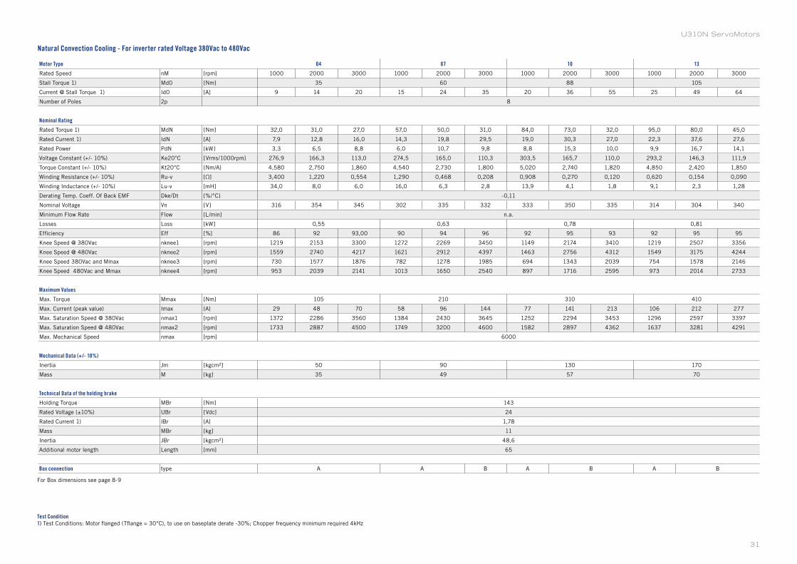
U310N ServoMotors
Motor Type 04 07 10 13
Rated Speed nM [rpm] 1000 2000 3000 1000 2000 3000 1000 2000 3000 1000 2000 3000
Stall Torque 1) Md0 [Nm] 35 60 88 105
Current @ Stall Torque 1) Id0 [A] 9 14 20 15 24 35 20 36 55 25 49 64
Number of Poles 2p 8
Nominal Rating
Rated Torque 1) MdN [Nm] 32,0 31,0 27,0 57,0 50,0 31,0 84,0 73,0 32,0 95,0 80,0 45,0
Rated Current 1) IdN [A] 7,9 12,8 16,0 14,3 19,8 29,5 19,0 30,3 27,0 22,3 37,6 27,6
Rated Power PdN [kW] 3,3 6,5 8,8 6,0 10,7 9,8 8,8 15,3 10,0 9,9 16,7 14,1
Voltage Constant (+/- 10%) Ke20°C [Vrms/1000rpm] 276,9 166,3 113,0 274,5 165,0 110,3 303,5 165,7 110,0 293,2 146,3 111,9
Torque Constant (+/- 10%) Kt20°C [Nm/A] 4,580 2,750 1,860 4,540 2,730 1,800 5,020 2,740 1,820 4,850 2,420 1,850
Winding Resistance (+/- 10%) Ru-v [Ω] 3,400 1,220 0,554 1,290 0,468 0,208 0,908 0,270 0,120 0,620 0,154 0,090
Winding Inductance (+/- 10%) Lu-v [mH] 34,0 8,0 6,0 16,0 6,3 2,8 13,9 4,1 1,8 9,1 2,3 1,28
Derating Temp. Coeff. Of Back EMF Dke/Dt [%/°C] -0,11
Nominal Voltage Vn [V] 316 354 345 302 335 332 333 350 335 314 304 340
Minimum Flow Rate Flow [L/min] n.a.
Losses Loss [kW] 0,55 0,63 0,78 0,81
Efficiency Eff [%] 86 92 93,00 90 94 96 92 95 93 92 95 95
Knee Speed @ 380Vac nknee1 [rpm] 1219 2153 3300 1272 2269 3450 1149 2174 3410 1219 2507 3356
Knee Speed @ 480Vac nknee2 [rpm] 1559 2740 4217 1621 2912 4397 1463 2756 4312 1549 3175 4244
Knee Speed 380Vac and Mmax nknee3 [rpm] 730 1577 1876 782 1278 1985 694 1343 2039 754 1578 2146
Knee Speed 480Vac and Mmax nknee4 [rpm] 953 2039 2141 1013 1650 2540 897 1716 2595 973 2014 2733
Maximum Values
Max. Torque Mmax [Nm] 105 210 310 410
Max. Current (peak value) Imax [A] 29 48 70 58 96 144 77 141 213 106 212 277
Max. Saturation Speed @ 380Vac nmax1 [rpm] 1372 2286 3560 1384 2430 3645 1252 2294 3453 1296 2597 3397
Max. Saturation Speed @ 480Vac nmax2 [rpm] 1733 2887 4500 1749 3200 4600 1582 2897 4362 1637 3281 4291
Max. Mechanical Speed nmax [rpm] 6000
Mechanical Data (+/- 10%)
Inertia Jm [kgcm²] 50 90 130 170
Mass M [kg] 35 49 57 70
Technical Data of the holding brake
Holding Torque MBr [Nm] 143
Rated Voltage (±10%) UBr [Vdc] 24
Rated Current 1) IBr [A] 1,78
Mass MBr [kg] 11
Inertia JBr [kgcm²] 48,6
Additional motor length Length [mm] 65
Box connection type A A B A B A B
Test Condition1) Test Conditions: Motor flanged (Tflange = 30°C), to use on baseplate derate -30%; Chopper frequency minimum required 4kHz
For Box dimensions see page 8-9
Natural Convection Cooling - For inverter rated Voltage 380Vac to 480Vac
31
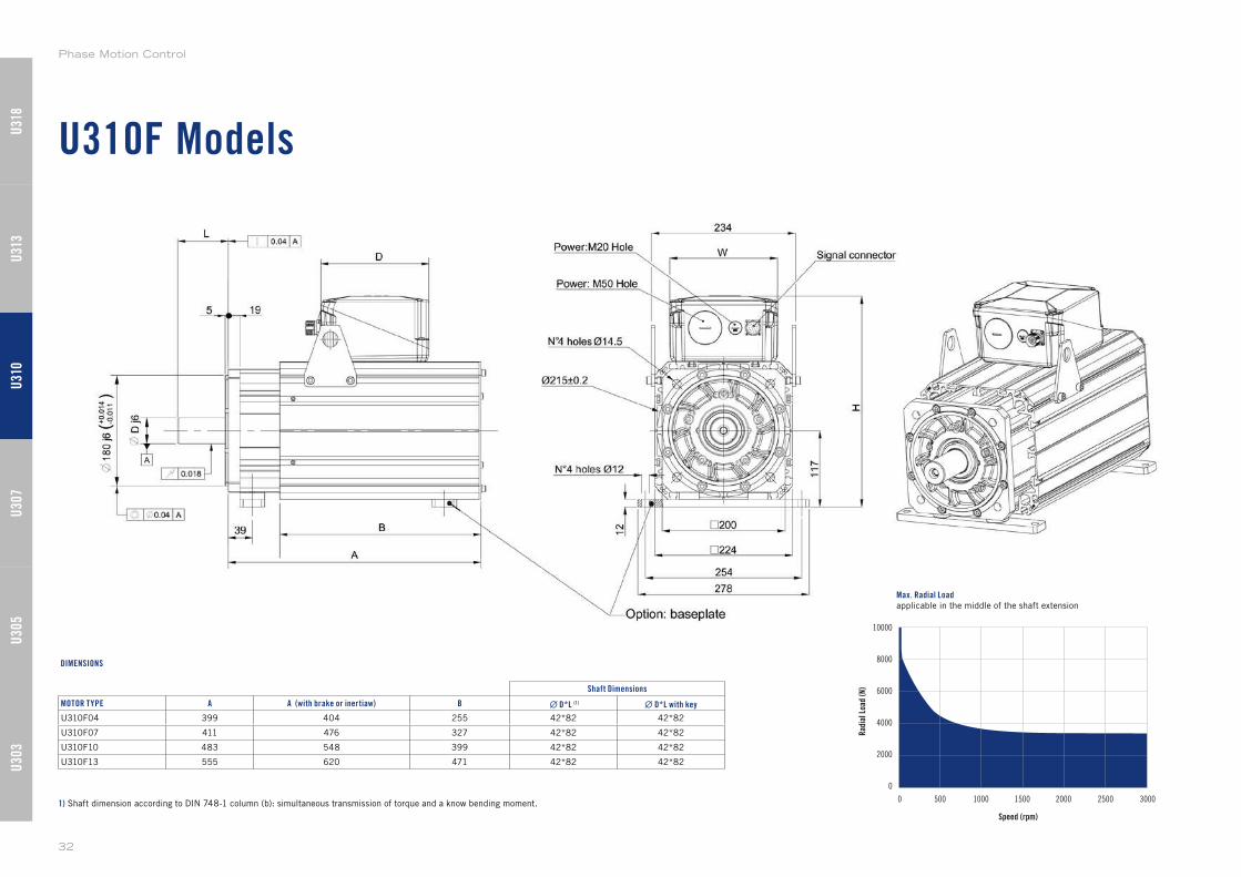
U310F Models
Speed (rpm)
10000
8000
6000
4000
2000
0
0 500 1000 1500 2000 2500 3000
Rad
ial L
oad
(N)
Max. Radial Loadapplicable in the middle of the shaft extension
1) Shaft dimension according to DIN 748-1 column (b): simultaneous transmission of torque and a know bending moment.
Shaft Dimensions
MOTOR TYPE A A (with brake or inertiaw) B ∙ D*L (1) ∙ D*L with key
U310F04 399 404 255 42*82 42*82
U310F07 411 476 327 42*82 42*82
U310F10 483 548 399 42*82 42*82
U310F13 555 620 471 42*82 42*82
DIMENSIONS
U30
3U
305
U31
0U
307
U31
3U
318
Phase Motion Control
32
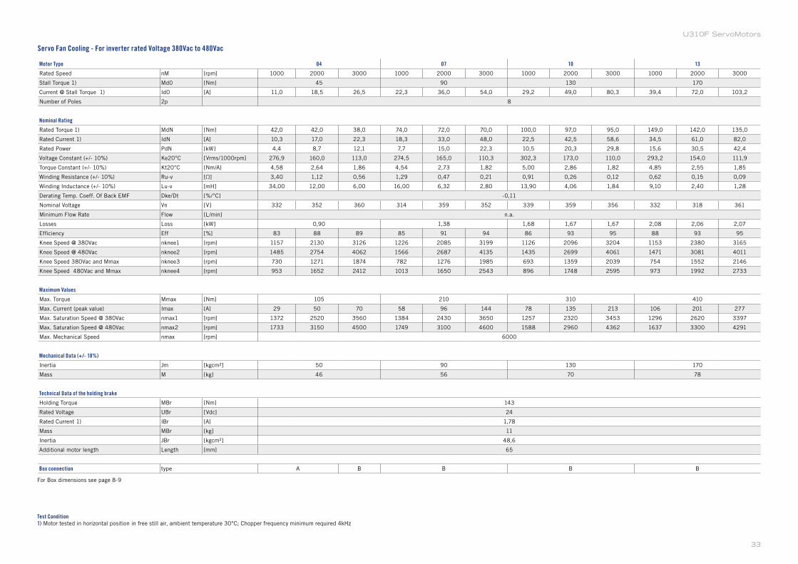
Motor Type 04 07 10 13
Rated Speed nM [rpm] 1000 2000 3000 1000 2000 3000 1000 2000 3000 1000 2000 3000
Stall Torque 1) Md0 [Nm] 45 90 130 170
Current @ Stall Torque 1) Id0 [A] 11,0 18,5 26,5 22,3 36,0 54,0 29,2 49,0 80,3 39,4 72,0 103,2
Number of Poles 2p 8
Nominal Rating
Rated Torque 1) MdN [Nm] 42,0 42,0 38,0 74,0 72,0 70,0 100,0 97,0 95,0 149,0 142,0 135,0
Rated Current 1) IdN [A] 10,3 17,0 22,3 18,3 33,0 48,0 22,5 42,5 58,6 34,5 61,0 82,0
Rated Power PdN [kW] 4,4 8,7 12,1 7,7 15,0 22,3 10,5 20,3 29,8 15,6 30,5 42,4
Voltage Constant (+/- 10%) Ke20°C [Vrms/1000rpm] 276,9 160,0 113,0 274,5 165,0 110,3 302,3 173,0 110,0 293,2 154,0 111,9
Torque Constant (+/- 10%) Kt20°C [Nm/A] 4,58 2,64 1,86 4,54 2,73 1,82 5,00 2,86 1,82 4,85 2,55 1,85
Winding Resistance (+/- 10%) Ru-v [Ω] 3,40 1,12 0,56 1,29 0,47 0,21 0,91 0,26 0,12 0,62 0,15 0,09
Winding Inductance (+/- 10%) Lu-v [mH] 34,00 12,00 6,00 16,00 6,32 2,80 13,90 4,06 1,84 9,10 2,40 1,28
Derating Temp. Coeff. Of Back EMF Dke/Dt [%/°C] -0,11
Nominal Voltage Vn [V] 332 352 360 314 359 352 339 359 356 332 318 361
Minimum Flow Rate Flow [L/min] n.a.
Losses Loss [kW] 0,90 1,38 1,68 1,67 1,67 2,08 2,06 2,07
Efficiency Eff [%] 83 88 89 85 91 94 86 93 95 88 93 95
Knee Speed @ 380Vac nknee1 [rpm] 1157 2130 3126 1226 2085 3199 1126 2096 3204 1153 2380 3165
Knee Speed @ 480Vac nknee2 [rpm] 1485 2754 4062 1566 2687 4135 1435 2699 4061 1471 3081 4011
Knee Speed 380Vac and Mmax nknee3 [rpm] 730 1271 1874 782 1276 1985 693 1359 2039 754 1552 2146
Knee Speed 480Vac and Mmax nknee4 [rpm] 953 1652 2412 1013 1650 2543 896 1748 2595 973 1992 2733
Maximum Values
Max. Torque Mmax [Nm] 105 210 310 410
Max. Current (peak value) Imax [A] 29 50 70 58 96 144 78 135 213 106 201 277
Max. Saturation Speed @ 380Vac nmax1 [rpm] 1372 2520 3560 1384 2430 3650 1257 2320 3453 1296 2620 3397
Max. Saturation Speed @ 480Vac nmax2 [rpm] 1733 3150 4500 1749 3100 4600 1588 2960 4362 1637 3300 4291
Max. Mechanical Speed nmax [rpm] 6000
Mechanical Data (+/- 10%)
Inertia Jm [kgcm²] 50 90 130 170
Mass M [kg] 46 56 70 78
Technical Data of the holding brake
Holding Torque MBr [Nm] 143
Rated Voltage UBr [Vdc] 24
Rated Current 1) IBr [A] 1,78
Mass MBr [kg] 11
Inertia JBr [kgcm²] 48,6
Additional motor length Length [mm] 65
Box connection type A B B B B
Test Condition1) Motor tested in horizontal position in free still air, ambient temperature 30°C; Chopper frequency minimum required 4kHz
For Box dimensions see page 8-9
Servo Fan Cooling - For inverter rated Voltage 380Vac to 480Vac
33
U310F ServoMotors
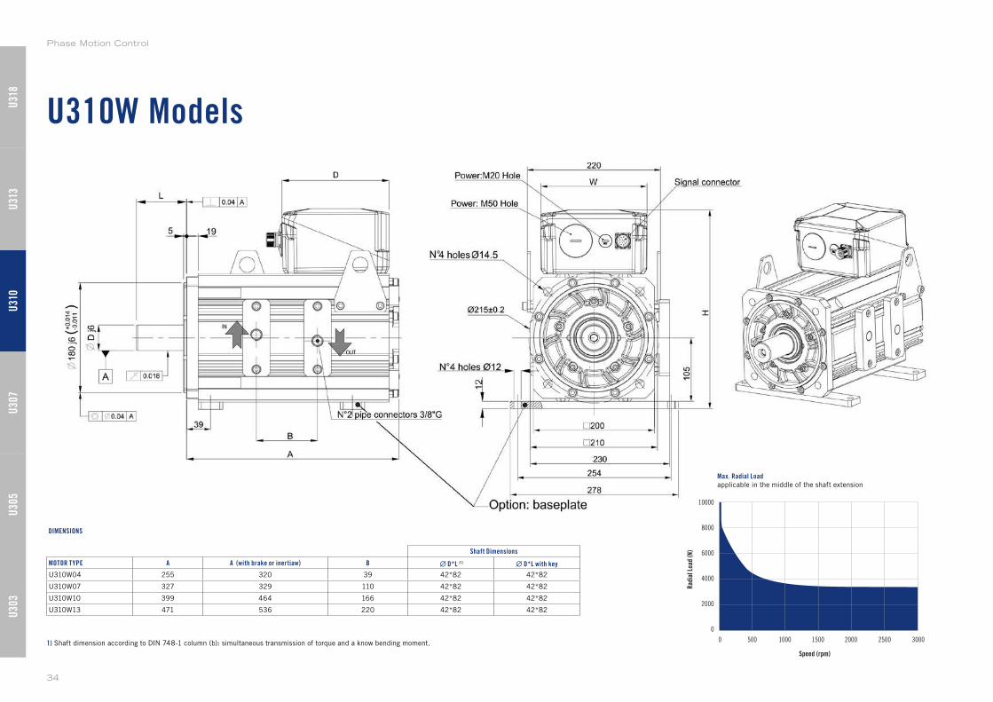
U310W Models
Speed (rpm)
10000
8000
6000
4000
2000
0
0 500 1000 1500 2000 2500 3000
Rad
ial L
oad
(N)
Max. Radial Loadapplicable in the middle of the shaft extension
1) Shaft dimension according to DIN 748-1 column (b): simultaneous transmission of torque and a know bending moment.
Shaft Dimensions
MOTOR TYPE A A (with brake or inertiaw) B ∙ D*L (1) ∙ D*L with key
U310W04 255 320 39 42*82 42*82
U310W07 327 329 110 42*82 42*82
U310W10 399 464 166 42*82 42*82
U310W13 471 536 220 42*82 42*82
DIMENSIONS
U30
3U
305
U31
0U
307
U31
3U
318
Phase Motion Control
34
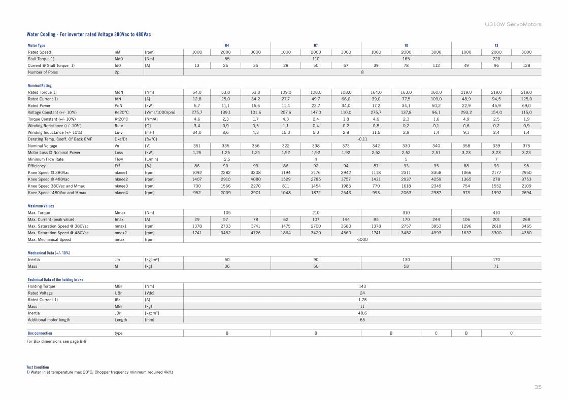
Motor Type 04 07 10 13
Rated Speed nM [rpm] 1000 2000 3000 1000 2000 3000 1000 2000 3000 1000 2000 3000
Stall Torque 1) Md0 [Nm] 55 110 165 220
Current @ Stall Torque 1) Id0 [A] 13 26 35 28 50 67 39 78 112 49 96 128
Number of Poles 2p 8
Nominal Rating
Rated Torque 1) MdN [Nm] 54,0 53,0 53,0 109,0 108,0 108,0 164,0 163,0 160,0 219,0 219,0 219,0
Rated Current 1) IdN [A] 12,8 25,0 34,2 27,7 49,7 66,0 39,0 77,5 109,0 48,9 94,5 125,0
Rated Power PdN [kW] 5,7 11,1 16,6 11,4 22,7 34,0 17,2 34,1 50,2 22,9 45,9 69,0
Voltage Constant (+/- 10%) Ke20°C [Vrms/1000rpm] 275,7 139,1 101,6 257,6 147,0 110,0 275,7 137,8 96,1 293,2 154,0 115,0
Torque Constant (+/- 10%) Kt20°C [Nm/A] 4,6 2,3 1,7 4,3 2,4 1,8 4,6 2,3 1,6 4,9 2,5 1,9
Winding Resistance (+/- 10%) Ru-v [Ω] 3,4 0,9 0,5 1,1 0,4 0,2 0,8 0,2 0,1 0,6 0,2 0,9
Winding Inductance (+/- 10%) Lu-v [mH] 34,0 8,6 4,3 15,0 5,0 2,8 11,5 2,9 1,4 9,1 2,4 1,4
Derating Temp. Coeff. Of Back EMF Dke/Dt [%/°C] -0,11
Nominal Voltage Vn [V] 351 335 356 322 338 373 342 330 340 358 339 375
Motor Loss @ Nominal Power Loss [kW] 1,25 1,25 1,24 1,92 1,92 1,92 2,52 2,52 2,51 3,23 3,23 3,23
Minimum Flow Rate Flow [L/min] 2,5 4 5 7
Efficiency Eff [%] 86 90 93 86 92 94 87 93 95 88 93 95
Knee Speed @ 380Vac nknee1 [rpm] 1092 2282 3208 1194 2176 2942 1118 2311 3358 1066 2177 2950
Knee Speed @ 480Vac nknee2 [rpm] 1407 2910 4080 1529 2785 3757 1431 2937 4259 1365 278 3753
Knee Speed 380Vac and Mmax nknee3 [rpm] 730 1566 2270 811 1454 1985 770 1618 2349 754 1552 2109
Knee Speed 480Vac and Mmax nknee4 [rpm] 952 2009 2901 1048 1872 2543 993 2063 2987 973 1992 2694
Maximum Values
Max. Torque Mmax [Nm] 105 210 310 410
Max. Current (peak value) Imax [A] 29 57 78 62 107 144 85 170 244 106 201 268
Max. Saturation Speed @ 380Vac nmax1 [rpm] 1378 2733 3741 1475 2700 3680 1378 2757 3953 1296 2610 3465
Max. Saturation Speed @ 480Vac nmax2 [rpm] 1741 3452 4726 1864 3420 4560 1741 3482 4993 1637 3300 4350
Max. Mechanical Speed nmax [rpm] 6000
Mechanical Data (+/- 10%)
Inertia Jm [kgcm²] 50 90 130 170
Mass M [kg] 36 50 58 71
Technical Data of the holding brake
Holding Torque MBr [Nm] 143
Rated Voltage UBr [Vdc] 24
Rated Current 1) IBr [A] 1,78
Mass MBr [kg] 11
Inertia JBr [kgcm²] 48,6
Additional motor length Length [mm] 65
Box connection type B B B C B C
Test Condition1) Water inlet temperature max 20°C; Chopper frequency minimum required 4kHz
For Box dimensions see page 8-9
Water Cooling - For inverter rated Voltage 380Vac to 480Vac
35
U310W ServoMotors
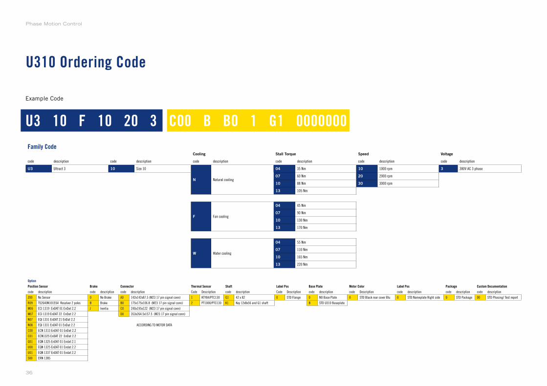
U310 Ordering Code
Example Code
Family CodeCooling Stall Torque Speed Voltage
code description code description code description code description code description code description
U3 Ultract 3 10 Size 10
N Natural cooling
04 35 Nm 10 1000 rpm 3 380V AC 3 phase
07 60 Nm 20 2000 rpm
10 88 Nm 30 3000 rpm
13 105 Nm
F Fan cooling
04 45 Nm
07 90 Nm
10 130 Nm
13 170 Nm
W Water cooling
04 55 Nm
07 110 Nm
10 165 Nm
13 220 Nm
Option
Position Sensor Brake Connector Thermal Sensor Shaft Label Pos Base Plate Motor Color Label Pos Package Custom Documentation
code description code description code description Code Description code description Code Description code description code Description code description code description code description
Z00 No Sensor 0 No Brake A0 142x142x87.5 (M23 17 pin signal conn) 1 KTY84/PTC130 G1 42 x 82 0 STD Flange 0 NO Base Plate 0 STD Black rear cover Blu 0 STD Nameplate Right side 0 STD Package 00 STD Phasing/ Test report
R09 TS2640N101E64 Resolver 2 poles B Brake B0 175x175x106.8 (M23 17 pin signal conn) 2 PT1000/PTC130 K1 Key 12x8x56 and G1 shaft B STD U310 Baseplate
M06 ECI 1319 EnDAT 01 EnDat 2.2 J Inertia C0 240x195x122 (M23 17 pin signal conn)
M07 ECI 1319 EnDAT 22 EnDat 2.2 D0 353x264.5x157.5 (M23 17 pin signal conn)
N07 EQI 1331 EnDAT 21 EnDat 2.2
N08 EQI 1331 EnDAT 01 EnDat 2.2 ACCORDING TO MOTOR DATA
C00 ECN 1313 EnDAT 01 EnDat 2.2
C01 ECN1325 EnDAT 22 EnDat 2.2
Q01 EQN 1325 EnDAT 01 Endat 2.1
U00 EQN 1325 EnDAT 01 Endat 2.2
U01 EQN 1337 EnDAT 01 Endat 2.2
S00 ERN 1385
U3 10 F 10 20 3 C00 B B0 1 G1 0000000
Phase Motion Control
36
U313 Models
U313N
U313F
U313W
Supported Models
U313N Models
Speed (rpm)
10000
8000
6000
4000
2000
0
0 500 1000 1500 2000 2500 3000
Rad
ial L
oad
(N)
Max. Radial Loadapplicable in the middle of the shaft extension
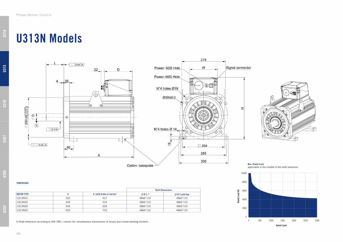
1) Shaft dimension according to DIN 748-1 column (b): simultaneous transmission of torque and a know bending moment.
Shaft Dimensions
MOTOR TYPE A A (with brake or inertia) ∙ D*L (1) ∙ D*L with key
U313N10 332 412 48k6*110 48k6*110
U313N20 439 519 48k6*110 48k6*110
U313N30 546 626 48k6*110 48k6*110
U313N40 653 733 48k6*110 48k6*110
DIMENSIONS
U30
3U
305
U31
0U
307
U31
3U
318
Phase Motion Control
38
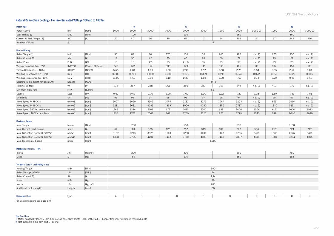
Motor Type 10 20 30 40
Rated Speed nM [rpm] 1000 2000 3000 1000 2000 3000 1000 2000 3000 2) 1000 2000 3000 2)
Stall Torque 1) Md0 [Nm] 100 190 260 350
Current @ Stall Torque 1) Id0 [A] 20 40 60 39 69 103 54 107 161 57 142 216
Number of Poles 2p 8
Nominal Rating
Rated Torque 1) MdN [Nm] 95 87 70 170 100 50 240 180 n.a. 2) 270 130 n.a. 2)
Rated Current 1) IdN [A] 19 35 42 35 43 28 50 74 n.a. 2) 45 52 n.a. 2)
Rated Power PdN [kW] 10 18 22 18 21..6 16 25 38 n.a. 2) 29 28 n.a. 2)
Voltage Constant (+/- 10%) Ke20°C [Vrms/1000rpm] 343 172 114 333 179 119 333 166 111 397 159 111
Torque Constant (+/- 10%) Kt20°C [Nm/A] 5,68 2,84 1,89 5,50 2,96 1,97 5,50 2,75 1,84 6,55 2,62 1,84
Winding Resistance (+/- 10%) Ru-v [Ω] 0,800 0,200 0,090 0,300 0,076 0,339 0,196 0,049 0,022 0,160 0,026 0,015
Winding Inductance (+/- 10%) Lu-v [mH] 18,00 4,50 2,00 9,10 2,33 1,03 6,00 1,50 0,73 5,70 0,90 0,52
Derating Temp. Coeff. Of Back EMF Dke/Dt [%/°C] -0,11
Nominal Voltage Vn [V] 378 367 358 361 350 357 358 345 n.a. 2) 413 310 n.a. 2)
Minimum Flow Rate Flow [L/min] n.a.
Losses Loss [kW] 0,69 0,69 0,70 1,00 1,00 1,00 1,22 1,22 1,23 1,50 1,50 1,51
Efficiency Eff [%] 93 96 97 95 96 97 96 97 n.a. 2) 95 97 n.a. 2)
Knee Speed @ 380Vac nknee1 [rpm] 1007 2069 3186 1055 2181 3175 1064 2203 n.a. 2) 961 2460 n.a. 2)
Knee Speed @ 480Vac nknee2 [rpm] 1281 2622 4031 1339 3000 4030 1350 2787 n.a. 2) 1230 3211 n.a. 2)
Knee Speed 380Vac and Mmax nknee3 [rpm] 666 1384 2101 679 1410 2140 681 1400 2006 613 1600 2083
Knee Speed 480Vac and Mmax nknee4 [rpm] 855 1762 2668 867 1700 2720 870 1779 2543 788 2040 2640
Maximum Values
Max. Torque Mmax [Nm] 280 550 830 1100
Max. Current (peak value) Imax [A] 62 123 185 125 232 349 189 377 564 210 524 747
Max. Saturation Speed @ 380Vac nmax1 [rpm] 1107 2213 3325 1143 2250 3400 1143 2286 3416 1030 2576 3416
Max. Saturation Speed @ 480Vac nmax2 [rpm] 1398 2795 4201 1443 3100 4100 1443 2887 4315 1301 3254 4315
Max. Mechanical Speed nmax [rpm] 6000
Mechanical Data (+/- 10%)
Inertia Jm [kgcm²] 200 390 590 780
Mass M [kg] 82 116 150 183
Technical Data of the holding brake
Holding Torque MBr [Nm] 300
Rated Voltage (±10%) UBr [Vdc] 24
Rated Current 1) IBr [A] 1,74
Mass MBr [kg] 18
Inertia JBr [kgcm²] 200
Additional motor length Length [mm] 80
Box connection type A B B C B C B C D
Test Condition1) Motor flanged (Tflange = 30°C), to use on baseplate derate -30% of the Md0; Chopper frequency minimum required 4kHz
2) Not available in S1 duty and DT100°C
For Box dimensions see page 8-9
Natural Convection Cooling - For inverter rated Voltage 380Vac to 480Vac
39
U313N ServoMotors
U313F Models
Speed (rpm)
10000
8000
6000
4000
2000
0
0 500 1000 1500 2000 2500 3000
Rad
ial L
oad
(N)
Max. Radial Loadapplicable in the middle of the shaft extension
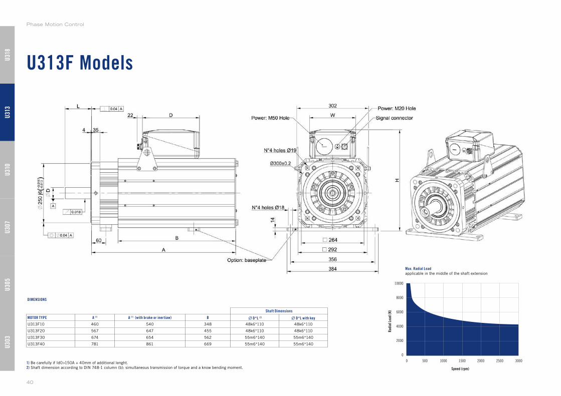
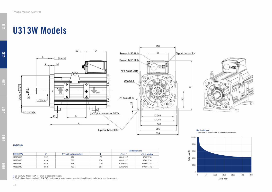
1) Be carefully if Id0>150A + 40mm of additional lenght.
2) Shaft dimension according to DIN 748-1 column (b): simultaneous transmission of torque and a know bending moment.
Shaft Dimensions
MOTOR TYPE A (1) A (1) (with brake or inertiaw) B ∙ D*L (2) ∙ D*L with key
U313F10 460 540 348 48k6*110 48k6*110
U313F20 567 647 455 48k6*110 48k6*110
U313F30 674 654 562 55m6*140 55m6*140
U313F40 781 861 669 55m6*140 55m6*140
DIMENSIONS
U30
3U
305
U31
0U
307
U31
3U
318
Phase Motion Control
40
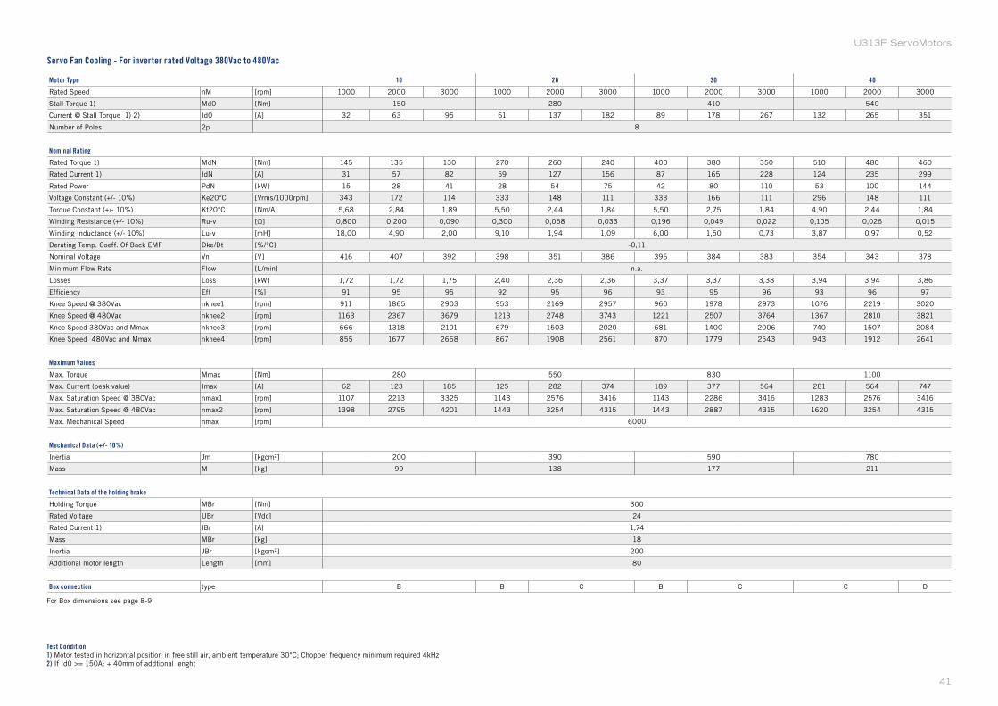
Motor Type 10 20 30 40
Rated Speed nM [rpm] 1000 2000 3000 1000 2000 3000 1000 2000 3000 1000 2000 3000
Stall Torque 1) Md0 [Nm] 150 280 410 540
Current @ Stall Torque 1) 2) Id0 [A] 32 63 95 61 137 182 89 178 267 132 265 351
Number of Poles 2p 8
Nominal Rating
Rated Torque 1) MdN [Nm] 145 135 130 270 260 240 400 380 350 510 480 460
Rated Current 1) IdN [A] 31 57 82 59 127 156 87 165 228 124 235 299
Rated Power PdN [kW] 15 28 41 28 54 75 42 80 110 53 100 144
Voltage Constant (+/- 10%) Ke20°C [Vrms/1000rpm] 343 172 114 333 148 111 333 166 111 296 148 111
Torque Constant (+/- 10%) Kt20°C [Nm/A] 5,68 2,84 1,89 5,50 2,44 1,84 5,50 2,75 1,84 4,90 2,44 1,84
Winding Resistance (+/- 10%) Ru-v [Ω] 0,800 0,200 0,090 0,300 0,058 0,033 0,196 0,049 0,022 0,105 0,026 0,015
Winding Inductance (+/- 10%) Lu-v [mH] 18,00 4,90 2,00 9,10 1,94 1,09 6,00 1,50 0,73 3,87 0,97 0,52
Derating Temp. Coeff. Of Back EMF Dke/Dt [%/°C] -0,11
Nominal Voltage Vn [V] 416 407 392 398 351 386 396 384 383 354 343 378
Minimum Flow Rate Flow [L/min] n.a.
Losses Loss [kW] 1,72 1,72 1,75 2,40 2,36 2,36 3,37 3,37 3,38 3,94 3,94 3,86
Efficiency Eff [%] 91 95 95 92 95 96 93 95 96 93 96 97
Knee Speed @ 380Vac nknee1 [rpm] 911 1865 2903 953 2169 2957 960 1978 2973 1076 2219 3020
Knee Speed @ 480Vac nknee2 [rpm] 1163 2367 3679 1213 2748 3743 1221 2507 3764 1367 2810 3821
Knee Speed 380Vac and Mmax nknee3 [rpm] 666 1318 2101 679 1503 2020 681 1400 2006 740 1507 2084
Knee Speed 480Vac and Mmax nknee4 [rpm] 855 1677 2668 867 1908 2561 870 1779 2543 943 1912 2641
Maximum Values
Max. Torque Mmax [Nm] 280 550 830 1100
Max. Current (peak value) Imax [A] 62 123 185 125 282 374 189 377 564 281 564 747
Max. Saturation Speed @ 380Vac nmax1 [rpm] 1107 2213 3325 1143 2576 3416 1143 2286 3416 1283 2576 3416
Max. Saturation Speed @ 480Vac nmax2 [rpm] 1398 2795 4201 1443 3254 4315 1443 2887 4315 1620 3254 4315
Max. Mechanical Speed nmax [rpm] 6000
Mechanical Data (+/- 10%)
Inertia Jm [kgcm²] 200 390 590 780
Mass M [kg] 99 138 177 211
Technical Data of the holding brake
Holding Torque MBr [Nm] 300
Rated Voltage UBr [Vdc] 24
Rated Current 1) IBr [A] 1,74
Mass MBr [kg] 18
Inertia JBr [kgcm²] 200
Additional motor length Length [mm] 80
Box connection type B B C B C C D
Test Condition1) Motor tested in horizontal position in free still air, ambient temperature 30°C; Chopper frequency minimum required 4kHz
2) If Id0 >= 150A: + 40mm of addtional lenght
Servo Fan Cooling - For inverter rated Voltage 380Vac to 480Vac
For Box dimensions see page 8-9
41
U313F ServoMotors
U313W Models
Speed (rpm)
10000
8000
6000
4000
2000
0
0 500 1000 1500 2000 2500 3000
Rad
ial L
oad
(N)
Max. Radial Loadapplicable in the middle of the shaft extension
1) Be carefully if Id0>150A + 40mm of additional lenght.
2) Shaft dimension according to DIN 748-1 column (b): simultaneous transmission of torque and a know bending moment.
Shaft Dimensions
MOTOR TYPE A (1) A (1) (with brake or inertiaw) B ∙ D*L (2) ∙ D*L with key
U313W10 332 412 75 48k6*110 48k6*110
U313W20 439 519 170 48k6*110 48k6*110
U313W30 546 536 279 60m6*140 60m6*140
U313W40 653 733 385 60m6*140 60m6*140
DIMENSIONS
U30
3U
305
U31
0U
307
U31
3U
318
Phase Motion Control
42
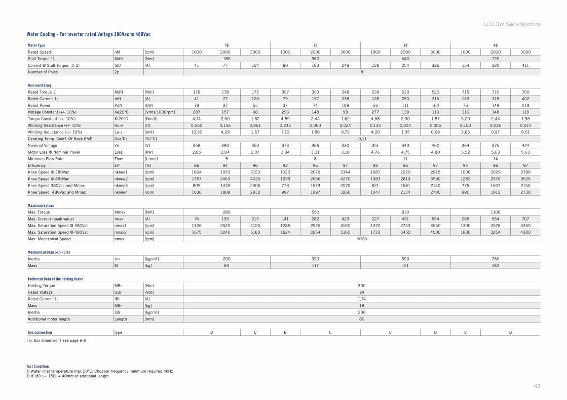
Motor Type 10 20 30 40
Rated Speed nM [rpm] 1000 2000 3000 1000 2000 3000 1000 2000 3000 1000 2000 3000
Stall Torque 1) Md0 [Nm] 180 360 540 720
Current @ Stall Torque 1) 2) Id0 [A] 41 77 124 80 160 248 128 254 326 154 320 411
Number of Poles 2p 8
Nominal Rating
Rated Torque 1) MdN [Nm] 179 178 175 357 353 348 539 530 520 715 710 700
Rated Current 1) IdN [A] 41 77 120 79 157 238 128 250 315 153 315 402
Rated Power PdN [kW] 19 37 55 37 74 109 56 111 164 75 149 219
Voltage Constant (+/- 10%) Ke20°C [Vrms/1000rpm] 287 157 98 296 148 98 277 139 113 316 148 119
Torque Constant (+/- 10%) Kt20°C [Nm/A] 4,74 2,60 1,62 4,89 2,44 1,62 4,58 2,30 1,87 5,20 2,44 1,96
Winding Resistance (+/- 10%) Ru-v [Ω] 0,560 0,156 0,061 0,243 0,060 0,024 0,135 0,034 0,205 0,100 0,026 0,014
Winding Inductance (+/- 10%) Lu-v [mH] 12,50 4,29 1,67 7,10 1,80 0,72 4,20 1,05 0,68 3,65 0,97 0,51
Derating Temp. Coeff. Of Back EMF Dke/Dt [%/°C] -0,11
Nominal Voltage Vn [V] 358 380 350 373 366 330 351 343 460 364 375 424
Motor Loss @ Nominal Power Loss [kW] 2,05 2,04 2,07 3,34 3,31 3,10 4,76 4,75 4,80 5,52 5,63 5,63
Minimum Flow Rate Flow [L/min] 5 8 11 14
Efficiency Eff [%] 86 94 96 92 96 97 92 96 97 94 96 97
Knee Speed @ 380Vac nknee1 [rpm] 1064 1933 3153 1020 2079 3344 1087 2220 2815 1006 2029 2780
Knee Speed @ 480Vac nknee2 [rpm] 1357 2463 4025 1299 2636 4270 1383 2813 3590 1283 2570 3525
Knee Speed 380Vac and Mmax nknee3 [rpm] 809 1418 2306 773 1573 2570 821 1681 2130 775 1507 2150
Knee Speed 480Vac and Mmax nknee4 [rpm] 1036 1808 2930 987 1997 3260 1047 2134 2700 990 1912 2730
Maximum Values
Max. Torque Mmax [Nm] 280 550 830 1100
Max. Current (peak value) Imax [A] 74 135 215 141 282 423 227 451 554 265 564 707
Max. Saturation Speed @ 380Vac nmax1 [rpm] 1326 2520 4100 1285 2576 4100 1372 2733 3550 1300 2576 3350
Max. Saturation Speed @ 480Vac nmax2 [rpm] 1675 3240 5160 1624 3254 5160 1733 3452 4500 1600 3254 4300
Max. Mechanical Speed nmax [rpm] 6000
Mechanical Data (+/- 10%)
Inertia Jm [kgcm²] 200 390 590 780
Mass M [kg] 83 117 151 183
Technical Data of the holding brake
Holding Torque MBr [Nm] 300
Rated Voltage UBr [Vdc] 24
Rated Current 1) IBr [A] 1,74
Mass MBr [kg] 18
Inertia JBr [kgcm²] 200
Additional motor length Length [mm] 80
Box connection type B C B C C D C D
Test Condition1) Water inlet temperature max 20°C; Chopper frequency minimum required 4kHz
2) If Id0 >= 150: + 40mm of addtional length
Water Cooling - For inverter rated Voltage 380Vac to 480Vac
For Box dimensions see page 8-9
43
U313W ServoMotors
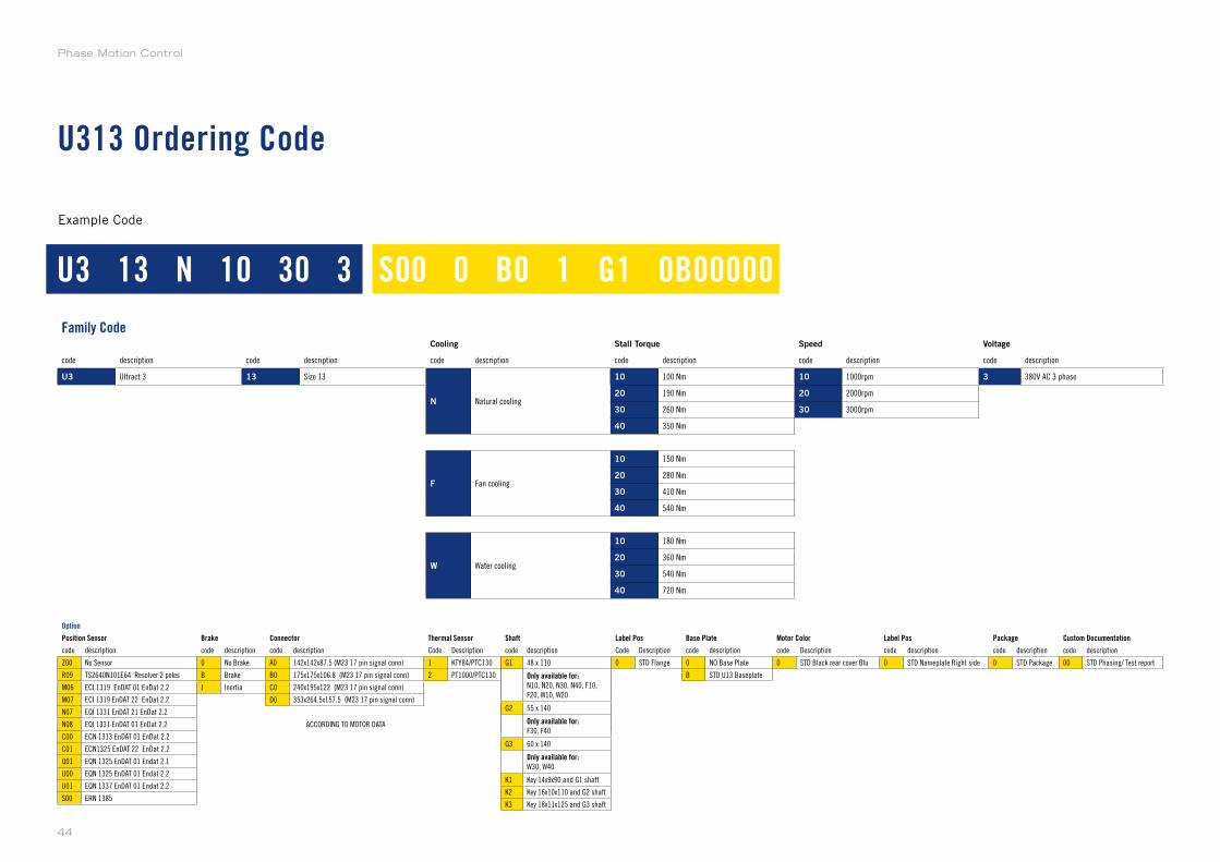
U313 Ordering Code
Example Code
Option
Position Sensor Brake Connector Thermal Sensor Shaft Label Pos Base Plate Motor Color Label Pos Package Custom Documentation
code description code description code description Code Description code description Code Description code description code Description code description code description code description
Z00 No Sensor 0 No Brake A0 142x142x87.5 (M23 17 pin signal conn) 1 KTY84/PTC130 0 STD Flange 0 NO Base Plate 0 STD Black rear cover Blu 0 STD Nameplate Right side 0 STD Package 00 STD Phasing/ Test report
R09 TS2640N101E64 Resolver 2 poles B Brake B0 175x175x106.8 (M23 17 pin signal conn) 2 PT1000/PTC130 B STD U13 Baseplate
M06 ECI 1319 EnDAT 01 EnDat 2.2 J Inertia C0 240x195x122 (M23 17 pin signal conn)
M07 ECI 1319 EnDAT 22 EnDat 2.2 D0 353x264.5x157.5 (M23 17 pin signal conn)
N07 EQI 1331 EnDAT 21 EnDat 2.2
N08 EQI 1331 EnDAT 01 EnDat 2.2 ACCORDING TO MOTOR DATA
C00 ECN 1313 EnDAT 01 EnDat 2.2
C01 ECN1325 EnDAT 22 EnDat 2.2
Q01 EQN 1325 EnDAT 01 Endat 2.1
U00 EQN 1325 EnDAT 01 Endat 2.2
U01 EQN 1337 EnDAT 01 Endat 2.2
S00 ERN 1385
Family CodeCooling Stall Torque Speed Voltage
code description code description code description code description code description code description
U3 Ultract 3 13 Size 13
N Natural cooling
10 100 Nm 10 1000rpm 3 380V AC 3 phase
20 190 Nm 20 2000rpm
30 260 Nm 30 3000rpm
40 350 Nm
F Fan cooling
10 150 Nm
20 280 Nm
30 410 Nm
40 540 Nm
W Water cooling
10 180 Nm
20 360 Nm
30 540 Nm
40 720 Nm
U3 13 N 10 30 3 S00 0 B0 1 G1 0B00000
code description
G1 48 x 110
Only available for:N10, N20, N30, N40, F10,
F20, W10, W20
G2 55 x 140
Only available for:F30, F40
G3 60 x 140
Only available for:W30, W40
K1 Key 14x9x90 and G1 shaft
K2 Key 16x10x110 and G2 shaft
K3 Key 18x11x125 and G3 shaft
Phase Motion Control
44
U318 Models
U318N
U318F
U318W
Supported Models
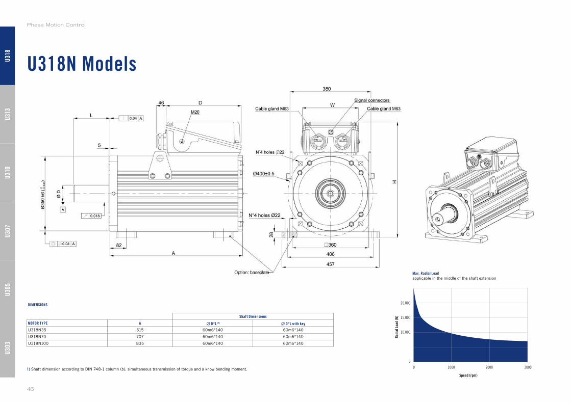
U318N Models
Max. Radial Loadapplicable in the middle of the shaft extension
1) Shaft dimension according to DIN 748-1 column (b): simultaneous transmission of torque and a know bending moment.
Shaft Dimensions
MOTOR TYPE A ∙ D*L (1) ∙ D*L with key
U318N35 515 60m6*140 60m6*140
U318N70 707 60m6*140 60m6*140
U318N100 835 60m6*140 60m6*140
DIMENSIONS
U30
3U
305
U31
0U
307
U31
3U
318
Phase Motion Control
46
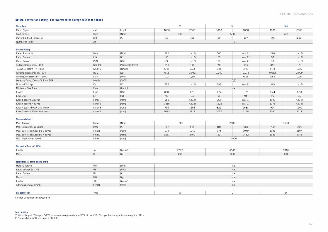
Motor Type 35 70 100
Rated Speed nM [rpm] 1000 2000 1000 2000 1000 2000
Stall Torque 1) Md0 [Nm] 300 560 730
Current @ Stall Torque 1) Id0 [A] 53 106 99 197 145 290
Number of Poles 2p 12
Nominal Rating
Rated Torque 1) MdN [Nm] 200 n.a. 2) 300 n.a. 2) 290 n.a. 2)
Rated Current 1) IdN [A] 35 n.a. 2) 53 n.a. 2) 57 n.a. 2)
Rated Power PdN [kW] 21 n.a. 2) 31 n.a. 2) 30 n.a. 2)
Voltage Constant (+/- 10%) Ke20°C [Vrms/1000rpm] 390 195 390 195 347 173
Torque Constant (+/- 10%) Kt20°C [Nm/A] 6,45 3,23 6,45 3,23 5,74 2,86
Winding Resistance (+/- 10%) Ru-v [Ω] 0,16 0,042 0,059 0,015 0,032 0,009
Winding Inductance (+/- 10%) Lu-v [mH] 2,2 0,55 1,1 0,28 0,65 0,16
Derating Temp. Coeff. Of Back EMF Dke/Dt [%/°C] -0,11
Nominal Voltage Vn [V] 396 n.a. 2) 393 n.a. 2) 349 n.a. 2)
Minimum Flow Rate Flow [L/min] n.a.
Losses Loss [kW] 0,97 1,01 1,24 1,26 1,44 1,63
Efficiency Eff [%] 95 94 94 94 95 95
Knee Speed @ 380Vac nknee1 [rpm] 959 n.a. 2) 966 n.a. 2) 1090 n.a. 2)
Knee Speed @ 480Vac nknee2 [rpm] 1215 n.a. 2) 1222 n.a. 2) 1378 n.a. 2)
Knee Speed 380Vac and Mmax nknee3 [rpm] 795 1658 822 1688 924 1900
Knee Speed 480Vac and Mmax nknee4 [rpm] 1023 2114 1052 2146 1180 2414
Maximum Values
Max. Torque Mmax [Nm] 1300 2500 3500
Max. Current (peak value) Imax [A] 252 504 484 969 762 1529
Max. Saturation Speed @ 380Vac nmax1 [rpm] 974 1949 974 1949 1095 2197
Max. Saturation Speed @ 480Vac nmax2 [rpm] 1231 2462 1231 2462 1383 2775
Max. Mechanical Speed nmax [rpm] 4000
Mechanical Data (+/- 10%)
Inertia Jm [kgcm²] 2820 5340 7010
Mass M [kg] 290 360 431
Technical Data of the holding brake
Holding Torque MBr [Nm] n.a.
Rated Voltage (±10%) UBr [Vdc] n.a.
Rated Current 1) IBr [A] n.a.
Mass MBr [kg] n.a.
Inertia JBr [kgcm²] n.a.
Additional motor length Length [mm] n.a.
Box connection Type D D D
Test Condition1) Motor flanged (Tflange = 30°C), to use on baseplate derate -30% of the Md0; Chopper frequency minimum required 4kHz
2) Not available in S1 duty and DT100°C
For Box dimensions see page 8-9
Natural Convection Cooling - For inverter rated Voltage 380Vac to 480Vac
47
U318N ServoMotors
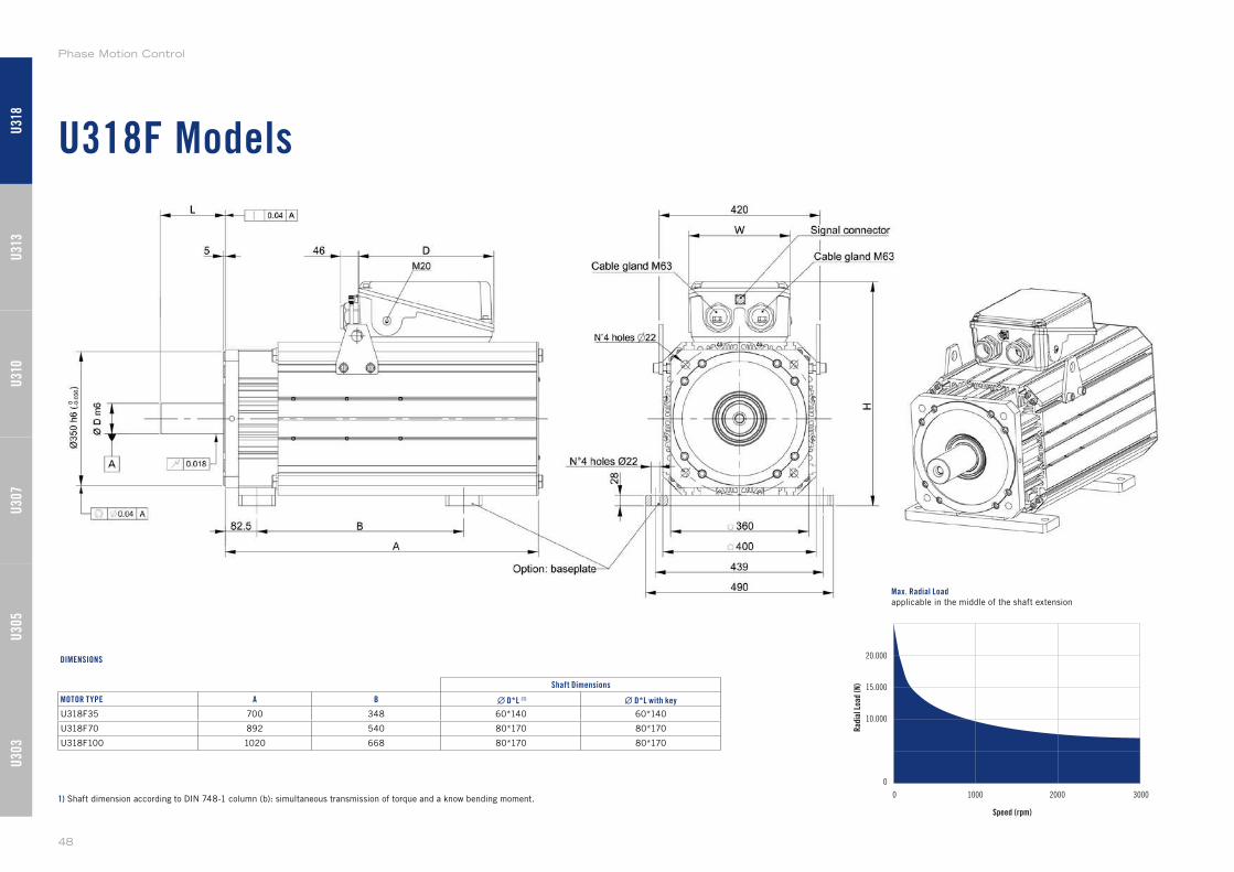
U318F Models
Max. Radial Loadapplicable in the middle of the shaft extension
1) Shaft dimension according to DIN 748-1 column (b): simultaneous transmission of torque and a know bending moment.
Shaft Dimensions
MOTOR TYPE A B ∙ D*L (1) ∙ D*L with key
U318F35 700 348 60*140 60*140
U318F70 892 540 80*170 80*170
U318F100 1020 668 80*170 80*170
DIMENSIONS
U30
3U
305
U31
0U
307
U31
3U
318
Phase Motion Control
48
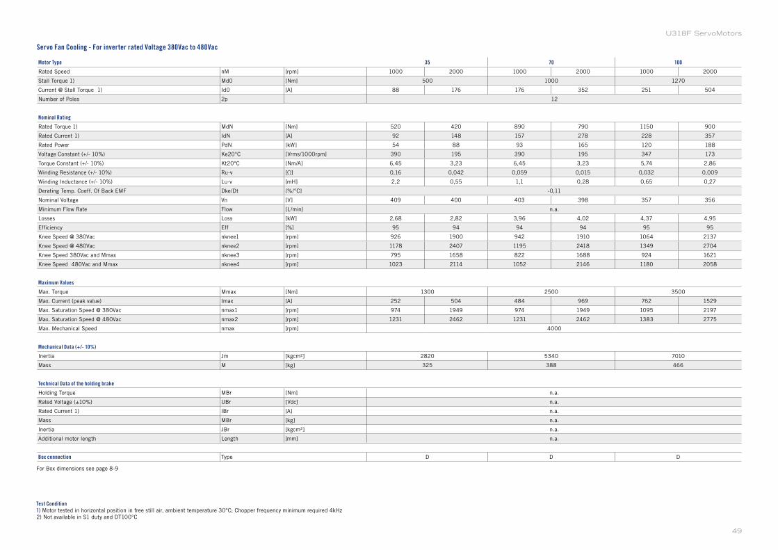
Motor Type 35 70 100
Rated Speed nM [rpm] 1000 2000 1000 2000 1000 2000
Stall Torque 1) Md0 [Nm] 500 1000 1270
Current @ Stall Torque 1) Id0 [A] 88 176 176 352 251 504
Number of Poles 2p 12
Nominal Rating
Rated Torque 1) MdN [Nm] 520 420 890 790 1150 900
Rated Current 1) IdN [A] 92 148 157 278 228 357
Rated Power PdN [kW] 54 88 93 165 120 188
Voltage Constant (+/- 10%) Ke20°C [Vrms/1000rpm] 390 195 390 195 347 173
Torque Constant (+/- 10%) Kt20°C [Nm/A] 6,45 3,23 6,45 3,23 5,74 2,86
Winding Resistance (+/- 10%) Ru-v [Ω] 0,16 0,042 0,059 0,015 0,032 0,009
Winding Inductance (+/- 10%) Lu-v [mH] 2,2 0,55 1,1 0,28 0,65 0,27
Derating Temp. Coeff. Of Back EMF Dke/Dt [%/°C] -0,11
Nominal Voltage Vn [V] 409 400 403 398 357 356
Minimum Flow Rate Flow [L/min] n.a.
Losses Loss [kW] 2,68 2,82 3,96 4,02 4,37 4,95
Efficiency Eff [%] 95 94 94 94 95 95
Knee Speed @ 380Vac nknee1 [rpm] 926 1900 942 1910 1064 2137
Knee Speed @ 480Vac nknee2 [rpm] 1178 2407 1195 2418 1349 2704
Knee Speed 380Vac and Mmax nknee3 [rpm] 795 1658 822 1688 924 1621
Knee Speed 480Vac and Mmax nknee4 [rpm] 1023 2114 1052 2146 1180 2058
Maximum Values
Max. Torque Mmax [Nm] 1300 2500 3500
Max. Current (peak value) Imax [A] 252 504 484 969 762 1529
Max. Saturation Speed @ 380Vac nmax1 [rpm] 974 1949 974 1949 1095 2197
Max. Saturation Speed @ 480Vac nmax2 [rpm] 1231 2462 1231 2462 1383 2775
Max. Mechanical Speed nmax [rpm] 4000
Mechanical Data (+/- 10%)
Inertia Jm [kgcm²] 2820 5340 7010
Mass M [kg] 325 388 466
Technical Data of the holding brake
Holding Torque MBr [Nm] n.a.
Rated Voltage (±10%) UBr [Vdc] n.a.
Rated Current 1) IBr [A] n.a.
Mass MBr [kg] n.a.
Inertia JBr [kgcm²] n.a.
Additional motor length Length [mm] n.a.
Box connection Type D D D
Test Condition1) Motor tested in horizontal position in free still air, ambient temperature 30°C; Chopper frequency minimum required 4kHz
2) Not available in S1 duty and DT100°C
Servo Fan Cooling - For inverter rated Voltage 380Vac to 480Vac
For Box dimensions see page 8-9
49
U318F ServoMotors
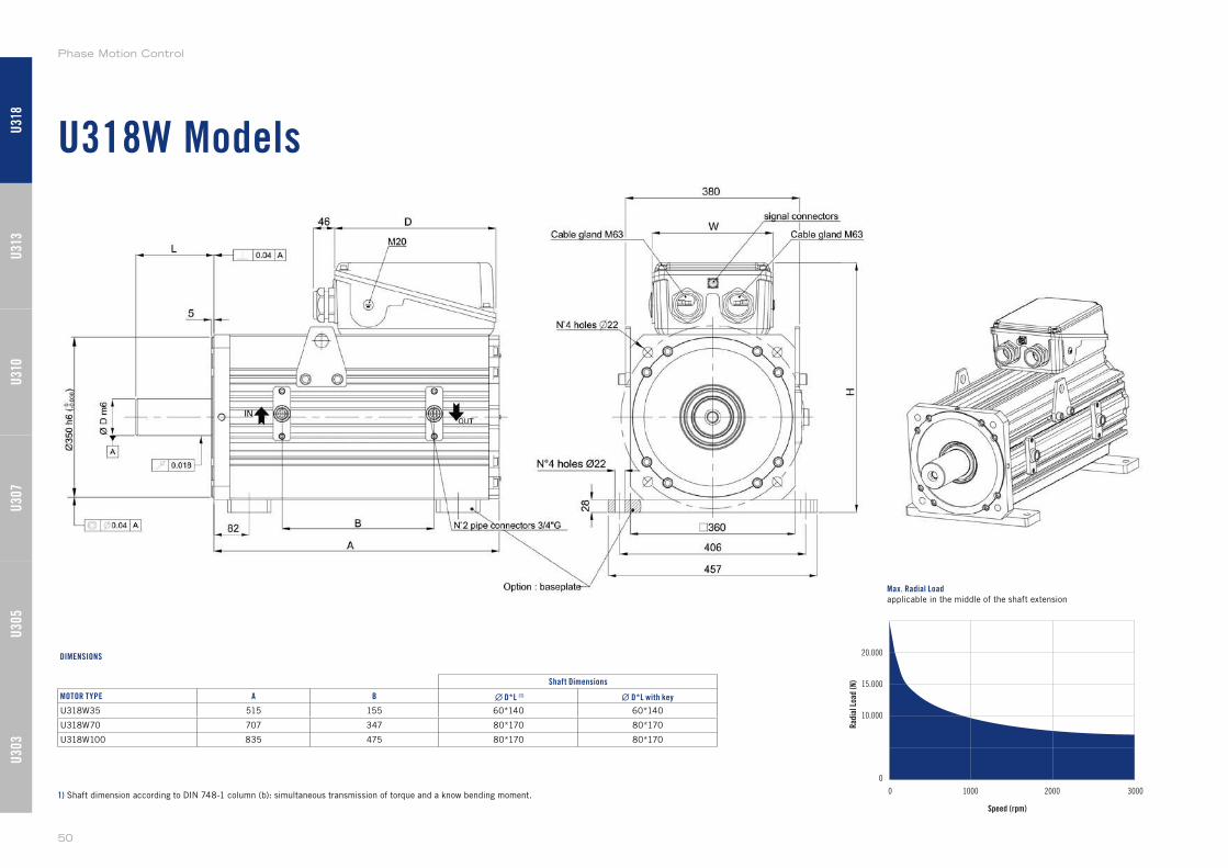
U318W Models
Max. Radial Loadapplicable in the middle of the shaft extension
1) Shaft dimension according to DIN 748-1 column (b): simultaneous transmission of torque and a know bending moment.
Shaft Dimensions
MOTOR TYPE A B ∙ D*L (1) ∙ D*L with key
U318W35 515 155 60*140 60*140
U318W70 707 347 80*170 80*170
U318W100 835 475 80*170 80*170
DIMENSIONS
U30
3U
305
U31
0U
307
U31
3U
318
Phase Motion Control
50
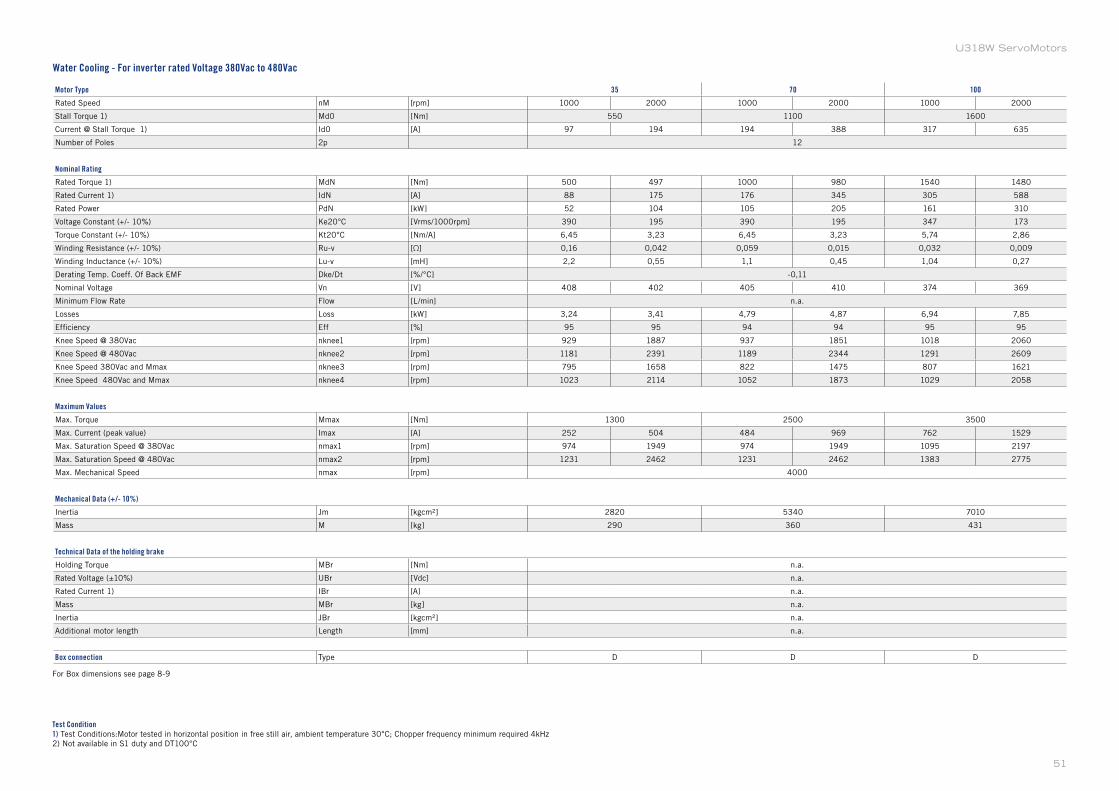
Motor Type 35 70 100
Rated Speed nM [rpm] 1000 2000 1000 2000 1000 2000
Stall Torque 1) Md0 [Nm] 550 1100 1600
Current @ Stall Torque 1) Id0 [A] 97 194 194 388 317 635
Number of Poles 2p 12
Nominal Rating
Rated Torque 1) MdN [Nm] 500 497 1000 980 1540 1480
Rated Current 1) IdN [A] 88 175 176 345 305 588
Rated Power PdN [kW] 52 104 105 205 161 310
Voltage Constant (+/- 10%) Ke20°C [Vrms/1000rpm] 390 195 390 195 347 173
Torque Constant (+/- 10%) Kt20°C [Nm/A] 6,45 3,23 6,45 3,23 5,74 2,86
Winding Resistance (+/- 10%) Ru-v [Ω] 0,16 0,042 0,059 0,015 0,032 0,009
Winding Inductance (+/- 10%) Lu-v [mH] 2,2 0,55 1,1 0,45 1,04 0,27
Derating Temp. Coeff. Of Back EMF Dke/Dt [%/°C] -0,11
Nominal Voltage Vn [V] 408 402 405 410 374 369
Minimum Flow Rate Flow [L/min] n.a.
Losses Loss [kW] 3,24 3,41 4,79 4,87 6,94 7,85
Efficiency Eff [%] 95 95 94 94 95 95
Knee Speed @ 380Vac nknee1 [rpm] 929 1887 937 1851 1018 2060
Knee Speed @ 480Vac nknee2 [rpm] 1181 2391 1189 2344 1291 2609
Knee Speed 380Vac and Mmax nknee3 [rpm] 795 1658 822 1475 807 1621
Knee Speed 480Vac and Mmax nknee4 [rpm] 1023 2114 1052 1873 1029 2058
Maximum Values
Max. Torque Mmax [Nm] 1300 2500 3500
Max. Current (peak value) Imax [A] 252 504 484 969 762 1529
Max. Saturation Speed @ 380Vac nmax1 [rpm] 974 1949 974 1949 1095 2197
Max. Saturation Speed @ 480Vac nmax2 [rpm] 1231 2462 1231 2462 1383 2775
Max. Mechanical Speed nmax [rpm] 4000
Mechanical Data (+/- 10%)
Inertia Jm [kgcm²] 2820 5340 7010
Mass M [kg] 290 360 431
Technical Data of the holding brake
Holding Torque MBr [Nm] n.a.
Rated Voltage (±10%) UBr [Vdc] n.a.
Rated Current 1) IBr [A] n.a.
Mass MBr [kg] n.a.
Inertia JBr [kgcm²] n.a.
Additional motor length Length [mm] n.a.
Box connection Type D D D
Test Condition1) Test Conditions:Motor tested in horizontal position in free still air, ambient temperature 30°C; Chopper frequency minimum required 4kHz
2) Not available in S1 duty and DT100°C
Water Cooling - For inverter rated Voltage 380Vac to 480Vac
For Box dimensions see page 8-9
51
U318W ServoMotors
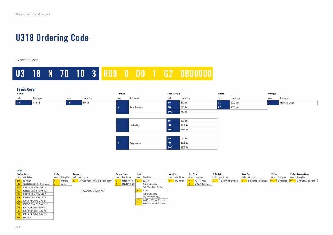
U318 Ordering Code
U3 18 N 70 10 3 R09 0 D0 1 G2 0B00000
Example Code
Option
Position Sensor Brake Connector Thermal Sensor Shaft Label Pos Base Plate Motor Color Label Pos Package Custom Documentation
code description code description code description code Description code description code description code description code description code description code description code description
Z00 No Sensor 0 No Brake D0 353x264.5x157.5 (M23 17 pin signal conn) 1 KTY84/PTC130 G1 60 x 140 1 0 STD Flange 0 NO Base Plate 0 STD Black rear cover Blu 0 STD Nameplate Right side 0 STD Package 00 STD Phasing/ Test report
R09 TS2640N101E64 Resolver 2 poles J Inertia 2 PT1000/PTC130 G2 80 x170 2 B STD U18 Baseplate
M06 ECI 1319 EnDAT 01 EnDat 2.2 K1 Key 18x11x125 and G1 shaft
M07 ECI 1319 EnDAT 22 EnDat 2.2 ACCORDING TO MOTOR DATA K2 Key 22x14x140 and G2 shaft
N07 EQI 1331 EnDAT 21 EnDat 2.2
N08 EQI 1331 EnDAT 01 EnDat 2.2
C00 ECN 1313 EnDAT 01 EnDat 2.2
C01 ECN1325 EnDAT 22 EnDat 2.2
Q01 EQN 1325 EnDAT 01 Endat 2.1
U00 EQN 1325 EnDAT 01 Endat 2.2
U01 EQN 1337 EnDAT 01 Endat 2.2
S00 ERN 1385
Family CodeName Cooling Stall Torque Speed Voltage
code description code description code description code description code description code description
U3 Ultract 3 18 Size 18
N Natural Cooling
35 300 Nm 10 1000 rpm 3 380V AC 3 phase
70 560 Nm 20 2000 rpm
100 730 Nm
F Fan Cooling
35 500 Nm
70 1000 Nm
100 1270 Nm
W Water Cooling
35 550 Nm
70 1100 Nm
100 1600 Nm
G1 60 x 140
Only available for:N35, N70, N100, F35, W35
G2 80 x170
Only available for:F70, F100, W70, W100
K1 Key 18x11x125 and G1 shaft
K2 Key 22x14x140 and G2 shaft
Phase Motion Control
52

53
U3 ServoMotors
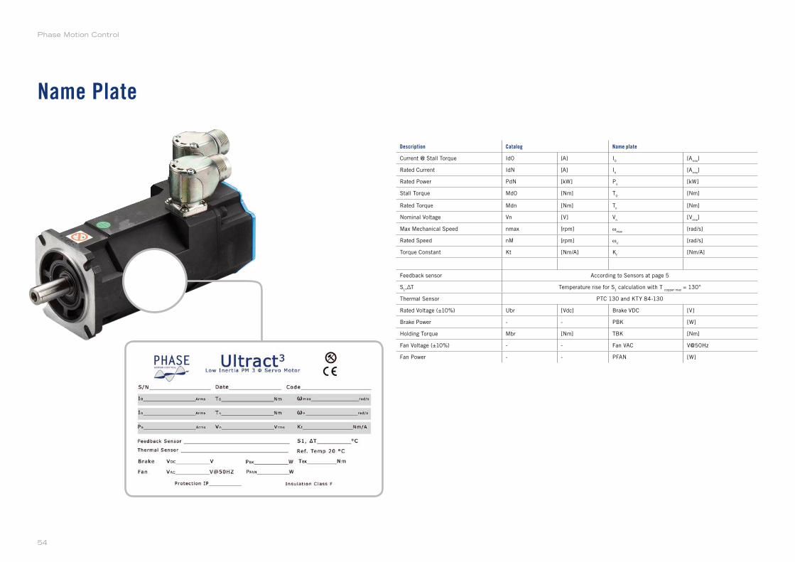
Name Plate
Description Catalog Name plate
Current @ Stall Torque Id0 [A] I0
[Arms
]
Rated Current IdN [A] In
[Arms
]
Rated Power PdN [kW] Pn
[kW]
Stall Torque Md0 [Nm] T0
[Nm]
Rated Torque Mdn [Nm] Tn
[Nm]
Nominal Voltage Vn [V] Vn
[Vrms
]
Max Mechanical Speed nmax [rpm] ωmax
[rad/s]
Rated Speed nM [rpm] ωn
[rad/s]
Torque Constant Kt [Nm/A] Kt
[Nm/A]
Feedback sensor According to Sensors at page 5
S1,ΔT Temperature rise for S
1 calculation with T
copper max = 130°
Thermal Sensor PTC 130 and KTY 84-130
Rated Voltage (±10%) Ubr [Vdc] Brake VDC [V]
Brake Power - - PBK [W]
Holding Torque Mbr [Nm] TBK [Nm]
Fan Voltage (±10%) - - Fan VAC V@50Hz
Fan Power - - PFAN [W]
Phase Motion Control
54
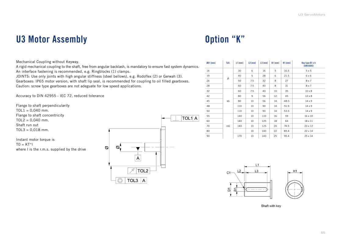
Option “K”U3 Motor Assembly
ØD1 [mm] Toll. L1 [mm] L2 [mm] L3 [mm] B1 [mm] H1 [mm] Key type B1 x h(DIN 6885)
14
j6
30 6 16 5 16.5 5 x 5
19 40 5 28 6 21.5 6 x 6
24 50 7.5 32 8 27 8 x 7
28 60 7.5 40 8 31 8 x 7
32
k6
60 7.5 40 10 35 10 x 8
42 80 9 56 12 45 12 x 8
45 80 10 56 14 48.5 14 x 9
48 110 10 90 14 51.5 14 x 9
50 110 10 90 14 53.5 14 x 9
55
m6
140 10 110 16 59 16 x 10
60 140 10 125 18 64 18 x 11
70 140 10 125 20 74.5 20 x 12
80 10 140 22 85.4 22 x 14
90 170 10 140 25 95.4 25 x 14
Mechanical Coupling without Keyway.
A rigid mechanical coupling to the shaft, free from angular backlash, is mandatory to ensure fast system dynamics.
An interface fastening is recommended, e.g. Ringblocks (1) clamps.
JOINTS: Use only joints with high angular stiffness (steel bellows), e.g. Rodoflex (2) or Gerwah (3).
Gearboxes: IP65 motor version, with shaft lip seal, is recommended for coupling to oil filled gearboxes.
Caution: screw type gearboxes are not adeguate for low speed applications.
Accuracy to DIN 42955 - IEC 72, reduced tolerance
Flange to shaft perpendicularity
TOL1 = 0,040 mm.
Flange to shaft concentricity
TOL2 = 0,040 mm.
Shaft run out
TOL3 = 0,018 mm.
Instant motor torque is
T0 = KT*l
where l is the r.m.s. supplied by the drive
55
U3 ServoMotors
Application Guidelines
Forward
AC brushless servo drive systems, based on rare earth PM magnets, provide the highest
level of dynamic performance and torque density available today. The trend to replace
conventional hydraulic, DC, stepper or inverter driven AC drives with brushless drives
yields to a new level of system performance, in terms of shorter cycle times, higher
productivity, improved accuracy coupled with shorter settling times, increased reliability
and longer life. In order to achieve the steep performance improvement which is
feasible with the new motors, however, a good understanding of the characteristics
of this technology is a prerequisite. In fact, just replacing a conventional motor with a
new technology drive on a machine not designed for high speed control could result in
unexpected problems and at times even in a deterioration of the machine operability.
These application guidelines were designed to provide a basic tool for the optimization of
new applications without prior knowledge of these new drives. For applications where the
performance or the motor stress is perceived to be critical, or where a full optimization
could be beneficial, contact the Factory.
Drive and Mechanical Linkage Selection
The success of all drive applications dictate a careful selection of the complete system
parameters. This in turn is based on a good understanding of the capabilities, which
are very high but often not fully understood, of modern brushless drive systems. In fact,
brushless drives are not motors, but complete, and complex, control systems; this results
in more degrees of design freedom, and more parameters to select, than a conventional
drive. From a conceptual viewpoint, a high performance brushless motor is more
similar to the membrane of a loudspeaker than to a standard induction motor. Just as
a loudspeaker, the motor has a very short response time, limited inertia, and therefore
it faithfully copies the control signal, whatever it may be. Just like a loudspeaker, the
quality of the result depends more on the system parameters and drive conditions than
on the motor itself. The design choices facing the system designer are thus at the same
time mechanical, electric and electronic, and such choices are interwoven, requiring an
interdisciplinary approach.
In particular, all systems require two fundamental selections:
» mechanical level: choice of the mechanical linkage, of the transmission ratio, of the
motion type conversion, of the couplings and clutches;
» electronic level: Feedback strategy, sensor type and number selection, sensor
placement, amplifier type, synchronization and control bus.
The next chapters outline a few guidelines to help with the selection as a function of the
application characteristics.
The Brushless Drive:Operational Principles, Characteristics and Limitations
All brushless servo systems consist of an electronic drive, a servo motor, and at least
one feedback sensor. All these component operate in a control loop: the drive accepts a
reference from the outside world, and feeds current to the motor. The motor is a torque
transducer and applies torque to the load. The load reacts, or accelerates, according
to its own characteristics. The sensor measures the load position, enabling the drive to
compare the motion with the reference and to change the motor current to force the
motion to copy the reference.
As an example, if constant speed is required, the drive would increase the current to the
motor until the motor speed equals the reference. If the load is suddenly stepped up,
Phase Motion Control
56
the speed diminishes; the sensor detects the speed change and consequently the drive
increases the motor torque to match the increased load and to return to the set speed.
From this example, a few deductions are possible:
» the speed accuracy is virtually independent of load and motor, but depends on the
quality of the sensor signal and the speed and control algorithm of the drive;
» the time lag between load perturbation and speed correction depends critically on the
speed and resolution of the sensor and on the parameters of the electronic drive.
Modern brushless servo drives react to sensor signals with time lags in the order of a
millisecond or less, providing for very high loop performance.
At this level, however, the propagation time through the mechanical linkages often
becomes the prime limit to the system dynamics.
As an example, consider a system in which a servo motor drives a constant speed, large
inertia load through a timing belt. The timing belt has a finite, and significant, elasticity.
Analyzing a speed correction at the millisecond timescale, the following sequence is
obtained:
» the drive sets a current level through the motor which applies a torque almost instantly;
» initially, while the belt is being stretched, the load does not accelerate as fast as the
motor;
» consequently, the motor reaches the set speed before the load; the sensor, on the
motor, cuts the current and consequently the torque;
» the increased tension of the belt slows the motor down forcing the drive to increase the
current again, and a new cycle is initiated.
In this example, the system is oscillating; the motor torque pulsates and so does the
load speed. The end result is noise, overheat and wear, none of which are clearly due to
the motor. However, superficial users would claim that the motor is noisy; in practice, if
this motor is replaced with an older generation, large and high inertia drive, the problem
would likely disappear, increasing the feeling that the new drives are not adequate.
This simplistic understanding is erroneous. In fact, analyzing the above example:
» the instability is due to the mismatch between the system reaction speed (high) and
the mechanical propagation or reaction time (long); the motor reacts quicker than the
time required by the system to settle through the new torque configuration;
» the possible solutions are:
either to reduce the mechanical system reaction time, by stiffening the linkage and
lowering the inertias, e.g. going direct drive or replacing the belt with a gearbox; or to
lower the speed of the control system, giving up some control bandwidth which would
have been achievable with the new technology.
The second solution, of course, sells away some quality, as it impairs the capability to
react quickly to sudden load variations. In fact, older drives, which were anyway slower,
compensated the lack of speed with a large motor inertia; on the other side, brushless
motors, where inertia is minimized, need a good bandwidth to guarantee good rotation
accuracy.
All this explains why brushless drives are relatively unforgiving of mechanical inaccuracies,
backlash, keyways etc.; for this reason, the best motors are manufactured with round
shaft without keyway, for interference coupling with conical fittings (e.g. Ring-feder) and
their shafts and flanges are machined to a reduced tolerance to remove the need for
flexible couplings. If a coupling is needed, it needs to be torsionally stiff, such as the
metallic bellows type.
In conclusion:
while traditional drive systems (DC of PM DC, inverter driven AC) would limit themselves,
with their own inertia and response time, the performance of the application, the high
level of the new brushless drives move the performance threshold above the mechanical
limits of most traditional applications. As a result, the design verification of the mechanical
57
U3 ServoMotors
system, and its upgrade to the new requirements, is more important than it used to be
up until now.
The success of a new application hinges critically on a good dynamical design of the
whole system.
A few rules can also be derived from the simple examples above:
» the speed accuracy does not depend on the motor but on the sensor;
» the following speed, and therefore the ability to compensate for sudden load variations,
depends critically on the stiffness and quality of the mechanical linkage.
The motor noise, which is often observed in poor or retrofit applications, is not due either
to the motor or the drive but often enough to a “primeval” mechanical linkage. In fact,
noise in due to the motor “hunting” for the correct torque; in this situation, the motor is
likely to overheat irrespectively of loading.
The same system might have worked well with an older drive, where the large motor
inertia “rolls over” all imperfections.
The dynamic study of the application is fundamental to the motor selection.
To this aim, this broad concept can be divided in two elements:
» large signal bandwidth: this is the raw ability to deliver enough torque and speed,
in sufficiently short time, to force the load on the desired trajectory. This depends
exclusively on motor and load torque and inertia, and can be studied considering all
components as infinitely stiff;
» small signal bandwidth or control bandwidth, which relates to the inverse of the settling
time. This is necessarily lower than any mechanical resonance frequency in the
system; its inverse expresses the settling time of the control loop, i.e. the time required
at the end of a motion command to settle in the target position within a required
accuracy. Typically, it will be impossible to achieve a settling time better than 2-3 times
the damping time of all the oscillations or resonances in the load and linkage.
As an example, consider the indexing axis of a high speed notching machine. The rate
target is set at 10 strokes per second, i.e. the drive starts and stops the workpiece in a
new position ten times per second. If the whole linkage (shaft, reducer, belts, ball screw
etc) has a first resonance frequency of 50 Hz, the system will settle in about 50-60 msec,
leaving only 40 msec for the move and the punch! This application is near impossible, as
very high torque and accelerations would be needed. However, if the linkage is stiffened,
by removing the belt, adopting a larger screw, etc. so that the resonance frequency of
the linkage is increased to 100 Hz, the settling time is reduced to 25-30 msec, the time
available for the move is doubled, the required torque is halved, and the application is
feasible.
Optimal Drive Design: the Transmission Ratio, the Type of Conversione, the Couplings
Brushless motors, like all other motors, are sized on supplied torque and not on output
power. In all applications, therefore, low motor speed yields to a low specific power and
relatively low efficiency. On the other hand, brushless motors have no minimum speed
(the speed depends only on the sensor used; there are applications whose axis speed
is 1 revolution/year); as a consequence, a high gearing is advisable only to minimize
the motor mass (e.g. with electric traction) or to maximize the efficiency; it is often not
advisable from the viewpoint of cost or dynamic performance. Wherever the motor is
applied directly on the load, the control bandwidth is maximized because maximum
transmission stiffness is achieved; consequently, these applications provide the best
position or following accuracy with the shortest settling time.
Before starting with the selection of the right drive for a specific system, it is necessary
to know the type of mechanical transmission which can be used. The most common
transmissions are the following:
Phase Motion Control
58
Rotation-rotation conversion
» timing belt;
» reducer with helical wheels and parallel axes;
» cycloid and epicyclic reducer;
» Harmonic Drive™;
» tangent screw reducer or Gleason gears.
Rotational-linear motion conversion
» timing belts;
» pinion-rack;
» metallic band;
» ball screw.
For any transmission system, the load parameters can be transferred to the motor axis
as follows.
If n = transmission ratio (ratio between the motor and the load speed, rad/m in the case
of a conversion from linear motion):
» Motor torque = Torque (thrust) to the load/n
» Motor speed = Load speed x n
» Load inertia reduced to the motor axis = inertia (or mass) of load/n2
Among all the listed transmissions, the first ones, which are the least expensive, are also
the slowest; they result in low control bandwidth (lower than 10 Hz, using a high stiffness
belt); for the same reason, it is important to avoid the ratios which make the load inertia
transferred to the motor axis too much higher than the motor one. The belt transmission
should not be applied for positioning applications with cycle times a lot shorter than one
second.
Gear reducers are a good solution, provided that their angular backlash is considerably
lower than the accuracy required by the system; the best type of reducer (the most
expensive too) is the epicyclic; there are special series of cycloid and epicycloid reducers
purpose designed for servo controls, where the angular backlash at the output shaft is
limited to 1-3 arc minutes. Such reducers are the only ones that can be specified for
applications with control bandwidth higher than 10 Hz. The “servo series” reducers are
designed to be coupled directly to the motor with a stiff coupling device, without keyway.
The Harmonic Drive™ gearbox was specifically designed for positioning. It has limited
size, high ratio and low backlash. The angular stiffness is not very good and the achievable
control bandwidth is in the 10-30 Hz range. Because of its limited efficiency, it should be
used for positioning only.
Tangent screw reducers fit in a class apart. These gears, although common and
inexpensive, are not suitable for position control. The tangent screw, whose efficiency
is based on an effective lubrication, display a low efficiency which drops dramatically at
low speed, because below a critical speed the oil film collapses, efficiency drops and a
quick wear ensues.
Wherever a rotary to linear conversion is required, ball screws provide a quality solution
up to about 4 m/s, especially if they are driven directly by the motor. Direct drive with
a low inertia motor generally avoids the need of a torque limiting clutch. For very long
movements it is necessary to check the flexure and torsional stiffness of the screw, which
may limit the system bandwidth. Longer movements are carried out with rack and pinion,
which have always a significant backlash which generally results in limit cycling and
motor noise. The traditional backlash elimination methods add stick-slip non linearity
instead, and so do friction wheels, typically with similar limit cycling results.
Fast and accurate movements can be obtained with metallic tapes replacing the timing
belts with superior stiffness. This technique, while not well known and therefore not
standardized, is able to reach excellent performances in the control of small loads (a
few kilos).
59
U3 ServoMotors
In general, however, linear motors rest as the best solution for high accuracy control of
a linear motion.
In order to select the most suitable reduction method and transmission ratio for a specific
application, it is useful to classify first the applications into two broad families:
» Power services: the motor supplies power to a process (spindles, traction, winding,
conveying etc.), where the dynamic performance is of marginal importance, the power
controlled is significant, the motor cost is an important fraction of the system cost;
» Position control or high rate cycling (electronic camshaft), in which most of the energy
is used to accelerate, to brake and to position objects in a short time and with a more
or less high accuracy.
Traditionally, the two above mentioned categories are referred to respectively as spindle
drives and axis drive.
In the first case, the dynamic properties are often not important, therefore simple speed
reducers are acceptable and, as the power is often relevant, a mechanical transmission with
a reduction stage is normally useful. In order to choose the best transmission ratio, consider
that up to ~ 4000 RPM, the cost and size of the motor decrease in a quasi linear way with
the increase of the transmission ratio. On the contrary, the cost of the transmission increases
step by step according to the number of gear stages or pulleys; from an application cost
viewpoint, the minimum overall cost can only be found in a few points, precisely:
» either with a direct drive;
» or at the speed corresponding to the maximum ratio which is possible with just one
reduction stage;
» or at the speed corresponding to the maximum ratio which is possible with two
reduction stages and so on.
The economic optimization, in this case, is carried out checking these points and adding
the costs of the motor to that of the reducer.
For all dynamic applications (axes) the situation is completely different. If the torque
required in the drive cycle is dominated by the inertial torques both of the motor and
of the load, for an increase in the reduction ratio there is a decrease in the impact of
the load inertia and an increase of the impact of the motor inertia. Consequently, for an
application where the required torque is exclusively inertial, the reduction ratio at which
the load inertia, translated to the motor axis, equals the motor inertia (inertial match) is
characterized by the minimum motor torque and therefore by the smallest motor.
For this reason, inertial matching was long considered the best gear ratio selection tool.
Such rule, on the contrary, is just a useful indication. In fact, the minimum size motor,
considering that the cost of a quality reducer can double the cost of the motor, does not
correspond to the lowest cost application sizing. Furthermore, the level of quality and
performance is determined a lot more by gear backlash and shaft elasticity than by the
motor itself. Consequently, a ratio selection which accounts for the motor only is clearly
flawed. A better set of rules is the following;
» any transmission ratio higher than the inertial ratio is wrong;
» the best ratio is always lower or equal to the inertial one, and it is obtained considering
the motor and reducer costs;
» high ratios always yield a narrower control bandwidth and a lower degree of accuracy
(with a higher energetic consumption) than what can be obtained with lower ratios.
These considerations explain the current attempt to replace step down gears with direct
drives.
Wherever the load inertia transferred to the motor shaft is more than a few times the
motor inertia, however, care must be taken, because the motor inertia is not there to
carry out a stabilizing action on the possible mechanical resonances or load disturbance
on the system. As a consequence, a high control bandwidth needs to be achieved, to
Phase Motion Control
60
compensate electronically what is not obtained by inertia alone; to do this, the mechanical
linkage in these applications needs to be of high quality, stiff and without backlash (no
keyways!).
From an analytical viewpoint, extreme direct drives mandate a check on the torsional
stiffness of the system. The torsional stiffness of the motor shaft needs to be considered
as well; this, although minimized in the U3 Motor design by means of large shafts, is
significant for the long and thin motors. In fact, the U3 Motor range was purposefully
overlapped, so that the same torque can be obtained either with a long and narrow motor
or with a short and stocky one. For this reason:
» long motors have a minimum moment of inertia; they are intended for high acceleration
with low inertia loads;
» stocky motors have a maximum torsional stiffness; they are intended for high inertia
loads, where the motor inertia is small compared to the load.
As a reference, the torsional stiffness of a shaft whose diameter is D and whose length
is L, made of steel, is:
while the frequency of torsional resonance of a load with inertia JI connected to an axis
with torsional stiffness Sm is:
In all applications with large inertia and short settling time, a check on the first torsional
resonance frequency is highly advisable.
Control Strategy Selection
All drive system can be configured according to three main control strategies:
» torque control (the speed depends on the load);
» speed control (the torque depends on the load);
» position control (the torque depends on the load)
The first strategy is the easiest to implement and can be used when it is necessary to control
a force or a pull (winders/unwinders, textile, tape/paper processing, etc.). Torque control
is native, or intrinsic to the brushless motors, which are always current controlled. For this
reason, torque control has minimum sensor requirement (just commutation or Hall sensor),
is very fast (control bandwidth >300 Hz) and intrinsically stable and robust irrespective of
load. Torque controlled drives are simple amplifiers which require no calibration or adjustment
whatsoever and are therefore the simplest controllers. Accuracy is not too high due to motor
friction, cogging, ripple, sensor drift; typically it can range in the 5-10% area.
In the multi-axes applications with very fast and modern NCs or controller boards, where
multiple axes must be linked (multiple electric gears and cams), or with adaptive control
or with variable parameters, a simple and effective strategy is to set the drives in torque
control mode and to assign the other loops to the NC. In this way the encoders are fed
to the NC, all drives are equal, intrinsically stable and need no programming; all the
system and control parameters (offsets, PID values, etc) are lumped in the NC or control
PC. The drives can be replaced without programming and no download of parameters is
necessary. The control signal to the drives is a simple differential torque reference, offset
insensitive. The encoders are fed directly to the NC; the drive only reads the commutation
system. This simple and elegant approach provides very good performance in multiple
systems without incurring the cost and complexity of high speed field buses, which are
anyway rather limited in the number of axes and in the achievable speed. On the down
side, it downloads on the NC or PC the processing of the encoders, which could be
61
U3 ServoMotors
cumbersome where very high resolution is needed.
Speed control is the most traditional strategy. It usually embodies an integration term so
that the speed error is limited to the system offsets. In the digital drives, the speed loop
is derived from the space loop (see next).
Position or space control in servo amplifiers is carried out only by digital drives (AX-V). In
this way, the steady state position and speed following error is limited to a few points of
the sensor, that is in the case of an encoder with 4096 pulse/revolutions, 1/16,000 of a
revolution. Position loop capability, inside or outside the drive, is necessary to synchronize
several axes (electrical axis or electronic cam).
Check of the Drive and Motor Sizing
After selecting the motor and the transmission, a check of the correct sizing of motor and
drive is required. Such check is easy for applications where speed and load are quite
steady or which vary on a timescale which is long with respect to the time constant of the
motor (or of the electronics). In this case, it is only necessary to check for the maximum
load to be within the specified limits of the motor and the electronics.
For the applications where the load varies on a fast cycle, verification should proceed
as follows:
1 Trace the speed/time diagram of the cycle, considering that the acquisition of a precise
position or speed requires, apart from the time determined by the limits on the speed
and acceleration of the system, also a settling time equal to 2-3 times the inverse of
the system control bandwidth;
2 Transfer the inertia and the loads of the system to the motor shaft;
3 Calculate the cycle of the accelerations and the inertial torques [acceleration x (motor
inertia + load inertia transferred to the motor shaft)], checking also the inertia of
couplings, clutches, transmission devices;
4 Add the load on the motor axis to the inertial torque and derive a torque/time diagram
in the cycle;
5 By inspection of the torque vs. time diagram obtain the root mean square value of the
torque: e.g. divide the cycle into time segments t1,t2....tn inside of which the torque
is constant; if the torque values in each segment of the cycle are respectively C1,C2...
Cn, the root mean square torque in the cycle is:
6
7 Calculate the root mean square or effective speed in the cycle veff with the same formula;
8 Calculate the mean torque in the cycle Cave;
9 Calculate the maximum duration time of the maximum torque in the cycle tcmax;
10 Calculate the required torque at the maximum speed Cwmax;
11 Calculate the maximum torque Cpk.
The data thus obtained needs to be compared with the motor and electronic limits to
validate the application.
Phase Motion Control
62
Motor Size Verification
Brushless motors are excellent torque transducers, linear to a peak torque several times
the nominal. As a consequence, the obtainable peak torque is usually determined only by
the choice of the electronic drive. The correct sizing of the motor is thermal and electric;
the optimally sized motor is the one which, on the worst load, settles at the correct
temperature rise, usually 40-50°C above the room temperature.
The complete check of the selection of the proper motor is carried out in three steps:
» Control of the peak or demagnetizing torque;
» Thermal dimensioning;
» Electric, or winding, dimensioning.
1 - Demagnetization current check
Compare the peak current, expressed by:
with the motor demagnetization current, considering that the motor demagnetization
current increases as the temperature decreases. This check is usually meaningful for
small motors only.
2 - Temperature rise check
Preliminarily, check that the point Ceff, veff is within in the continuous operation area
(S1) of the chosen motor. More accurately, the temperature rise of the motor can be
predicted by:
where Ln represents the nominal losses of the motor with temperature rise of 65°C.
If the predicted temperature rise is higher than the motor maximum or acceptable
temperature rise, it is necessary to select a larger motor.
NOTE: the excessive temperature rise is generally the only good reason for the use of a
larger motor.
3 - Electric sizing check
At the maximum speed, the voltage required by the motor to supply the required torque
must be lower or equal to what is available from the drive, for the minimum mains supply
voltage which is specified for full specification operation (usually 90% of the nominal
voltage).
If Emin is the voltage value which can be supplied by the electronic power supply at the
minimum supply voltage, it is necessary to check that:
If this condition is not verified, it is necessary to choose a motor with a higher speed
winding; this will of course also require a higher drive current.
63
U3 ServoMotors
WORLDWIDE SUPPORT AND DISTRIBUTION NETWORK
Phase Motion Control, France
Phase Automation S.a.r.l.
22 Rue Jean-Louis Calderon
69120, Vaulx-en-velin
www.phase-automation.com
Phase Motion Control Italy
Company headquarters
Phase Motion Control S.p.a.
Via Adamoli 461
16141 Genova, Italy
www.phase.eu
Phase Motion Control, Austria
Phase Automation GmbH
Blindendorf 88,
4312 Ried in der Riedmark
www.phase.eu
Phase Motion Control, U.S.A.
Phase USA, Inc.
587 N. Edgewood Ave
Wood Dale, IL 60191 – USA
www.phaseusa.us
Rel
ease
07-
2017


![BMD - · PDF fileFocus on our synchronous servomotors ... Back EMF constant R pp [W] Stator phase-phase resistance L pp ... depend on motor size](https://img.pdfslide.net/doc/110x75/5aa3edb87f8b9ada698ee0ad/bmd-focus-on-our-synchronous-servomotors-back-emf-constant-r-pp-w-stator.jpg)