Embed Size (px)
Citation preview

UBC Social Ecological Economic Development Studies (SEEDS) Sustainability Program
Student Research Report
Stadium Neighborhood Underground Parkade and Water Storage
Paulina Buskas, Julia Dunlop, Daniel Luo, Wesley Prahalad, Steven Rintoul, Luthfi Subagio
University of British Columbia
CIVL 446
Themes: Water, Climate, Land
April 8, 2019
Disclaimer: “UBC SEEDS Sustainability Program provides students with the opportunity to share the
findings of their studies, as well as their opinions, conclusions and recommendations with the UBC
community. The reader should bear in mind that this is a student research project/report and is not an
official document of UBC. Furthermore, readers should bear in mind that these reports may not reflect
the current status of activities at UBC. We urge you to contact the research persons mentioned in a
report or the SEEDS Sustainability Program representative about the current status of the subject matter
of a project/report”.

Stadium Neighborhood Underground Parkade and Water Storage Project
Final Design Report
University of British Columbia - UBC SEEDS Sustainability Program Engineering Design Project II - CIVL 446 April 7th, 2019 Shearwater Designs - Team 22 Paulina Buskas, Julia Dunlop, Daniel Luo, Wesley Prahalad, Steven Rintoul, Luthfi Subagio

Executive Summary
Shearwater designs has been retained by UBC Campus and Community Planning to design an
integrated stormwater and parkade structure. The structure will improve stormwater detention
infrastructure, handle changing land uses due to the proposed Stadium Neighborhood
development, and provide parking for the new Thunderbird Stadium. The project aims to
integrate sustainable design with UBC athletics to showcase UBC’s commitment to
sustainability. This report and its proposed design emulate UBC’s objectives as stated in the
UBC Integrated Stormwater Management Plan [1].
The project is located northeast of the intersection of Southwest Marine Drive and West 16th
Avenue. The design features a 3500 m3 underground water detention vault that feeds an
infiltration trench and adjacent bioswales for overflow. A three level parkade will be constructed
on top of the detention vault, with entry on West 16th Avenue. A Green roof and rain gardens
are incorporated into the parkade exterior.
The current estimated cost of this project will be $12 million with an annual maintenance cost of
$32,000. The project’s latest construction start date and earliest construction finish date are May
1st 2019, and December 28th 2019, respectively.

Table of Contents
1.0 Project Overview 4
1.1 Objective 4
1.2 Design Methodology 6
1.3 Design Criteria and Assumptions 6
2.0 Analysis and Assessments 8
2.1 Overview 8
2.2 Geotechnical Analysis 8
2.3 Seismic Assessment 9
2.4 Hydraulic Analysis 9
2.5 Life Cycle Assessment 11
3.0 Parkade Structure 12
3.1 Overview 12
3.2 Layout and Traffic Management 12
3.3 Loading 12
3.4 Structural System 12
3.5 Foundation Design 13
3.6 Material Selection 13
4.0 Hydraulic Substructure 14
4.1 Overview 14
4.2 Detention Structure 14
4.3 Preliminary Treatment 15
4.4 Soakaway Pits 16
5.0 Natural Systems 18
5.1 Overview 18
5.2 Bioswales 18
5.3 Rain Gardens 19
5.4 Green Roofs 19
6.0 Construction Plan 20
6.1 Overview 20
6.2 Tasks 20
6.3 Scheduling 22
7.0 Operations and Maintenance 23
7.1 Overview 23
7.2 Parkade Structure 23
1

7.3 Hydraulic Substructure 23
7.4 Natural Systems 24
7.5 Safety Plan 24
8.0 Cost 25
8.1 Overview 25
8.2 Operations and Maintenance 26
9.0 Future Considerations 27
10.0 References 28
2

List of Tables
Table 1: Pipe Sizing for Dry Detention Vault 7
Table 2: Member Contributions 15
Table 3: Summary of Class A Cost Estimate 25
List Of Figures
Figure 1: Site Overhead 5
Figure 2: Junction 26 and 16th Ave Catchment During Peak Flow 10
Figure 3: Total Flow During 100 Year Storm at Junction 26 11
Figure 4: Stormceptor EFO 6 [15] 16
Figure 5: Overview of Project Schedule 22
3

1.0 Project Overview
1.1 Objective
As a part of the Stadium Road Neighbourhood project, the aging Thunderbird Stadium will be upgraded
and relocated to the site of the existing parking lot on East Mall and W 16th Ave. The current stadium
will be replaced by residential buildings. With the removal of the existing stadium parking lot, there is a
need for new parking infrastructure. This development has the potential to increase the impervious
surface in the area, thus increasing the runoff. One of the concerns with runoff on the UBC campus is
the potential erosion of nearby cliffs west of campus. Flooding from large storms is also a growing
concern with the impacts of climate change. UBC Campus and Community Planning is seeking solutions
to manage stormwater using natural stormwater management techniques in the vicinity of the new
Stadium Road Neighborhood. The objective of this project is to design a mixed-use parkade and
stormwater management system to serve the new development and address the growing flooding
concerns, in accordance with UBC Vancouver Campus Integrated Stormwater Management Plan (ISMP)
[1]. The team aims to achieve the following with the design of this mixed-use parkade and stormwater
management system:
1. Promote UBC’s commitment to sustainability and innovation by incorporating naturalized and
innovative stormwater management systems to accommodate a 1 in 100 year storm volume
2. Combine the activities of UBC Athletics with sustainable infrastructure to showcase innovation
as sustainable design at UBC
3. Address the anticipated increase in demand for both motorized and non-motorized parking for
the new Stadium Road Neighborhood
4

The proposed site for the mixed-use parkade and stormwater management system is a forested plot of
land on the northside of W. 16th Ave, between SW Marine Dr. and East Mall. It is south-east of the
existing Thunderbird Stadium and adjacent parking lot. A walking pathway runs along W. 16th Ave,
which will have to be removed and replaced. The parkade will connect directly to W. 16th Ave, so traffic
routing must be integrated with existing traffic flow. Excavation will be done directly adjacent to W. 16th
Ave, so care must be taken to minimize the impact on the bearing soil of the roadway. The elevation
above sea level of the site varies from 75.0 m (most southwest corner) to 89.0 m. Figure 1 below is an
overhead photo of the proposed site generated from the Google Earth Pro program.
Figure 1: Site Overhead
5

1.2 Design Methodology
The mixed-use parkade and stormwater management system was split into 3 main design components:
● Parkade structure
● Hydraulic substructure
● Natural systems
The parkade structure has the capacity to replace the existing parking infrastructure at Thunderbird
Stadium, while aiming to reduce congestion and idling time. The long term vision for the parkade is to
transition parts of the parkade into a community/recreation space. The hydraulic substructure is
designed to control peak flows of the 100 year, 24 hour storm and infiltrate at the 2 year,
predevelopment rate to achieve net zero water leaving the site, as stated. The natural systems are
designed to handle overflow from the dry detention vault and provide resilience to the stormwater
management system. They will also add to the aesthetic of the development, showcasing sustainability
at a visible location on campus.
1.3 Design Criteria and Assumptions
The project was designed according to various standards and guidelines. These guidelines are referenced
directly in the following design summaries, and are listed below.
Parkade Structure:
● BC Building Code (BCBC) 2018 [2]
● National Building Code of Canada (NBCC) 2015 [3]
● Vancouver Parking and Loading Design Supplement (VPLDS) [4]
● CSA S413 Parkade Manual [5]
Dry Detention Vault:
● Metro Vancouver Best Management Practices Guide for Stormwater [6]
6
Soakaway Pits:
● Metro Vancouver Stormwater Source Control Guidelines 2012 [7]
● BRE Soakaway Design [8]
Natural Systems:
● Metro Vancouver Stormwater Source Control Guidelines 2012 [7]
● Climate Projects for Metro Vancouver 2016 [9]
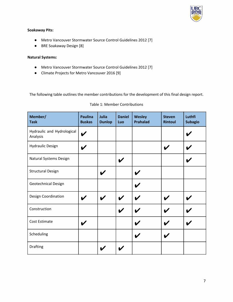
The following table outlines the member contributions for the development of this final design report.
Table 1: Member Contributions
Member/ Task
Paulina Buskas
Julia Dunlop
Daniel Luo
Wesley Prahalad
Steven Rintoul
Luthfi Subagio
Hydraulic and Hydrological Analysis ✔ ✔
Hydraulic Design ✔ ✔ ✔
Natural Systems Design ✔ ✔
Structural Design ✔ ✔
Geotechnical Design ✔
Design Coordination ✔ ✔ ✔ ✔ ✔ ✔
Construction ✔ ✔ ✔ ✔
Cost Estimate ✔ ✔ ✔ ✔
Scheduling ✔ ✔
Drafting ✔ ✔
7

2.0 Analysis and Assessments
2.1 Overview
Analysis and assessments for the project have been completed and are described in depth in the
Preliminary Design Report [10] submitted in November 2018. Further analysis and additional Seismic
analysis are described below.
2.2 Geotechnical Analysis
A geotechnical investigation was not completed at the site. Further geotechnical investigation of the site
should be completed prior to detailed foundation and excavation design. For purposes of preliminary
design, geotechnical conditions of the site are taken from the investigation done by GeoPacific
Consultants Ltd. for UBC Properties Trust for the proposed Mixed Commercial/Residential Development
Lot 10, UBC South Campus, Wesbrook Drive at 16th Avenue, Vancouver B.C. [11].
The subsurface geotechnical profile is interpreted from the UBC HydroGeo 2002 Report done by Piteau
Associates Engineering Ltd. [12]. A profile is interpreted at a cross section approximately 1 km north of
the site, which is taken to represent the profile of our site, given the lack of geotechnical information
closer to the site. At Lower Mall, the subsurface profile consists of 0.5 m of surface soil, underlain by
approximately 5 m of surface till, and 55 m of a Quadra sand. The water table of the Point Grey
Peninsula is located at an estimated depth of 60 meters below the project’s location. There is a low risk
of contaminating the groundwater with infiltration techniques. The surface till unit was treated as a
loamy sand, which has a hydraulic conductivity of 1.7 x 10⁻⁵ m/s according to [12], while the Quadra
8

Sand has a hydraulic conductivity of 4.8 x 10⁻⁴ m/s according to the Piteau report [12]. These hydraulic
conductivity values are used in the design of the soakaway pits described in Section 4.4.
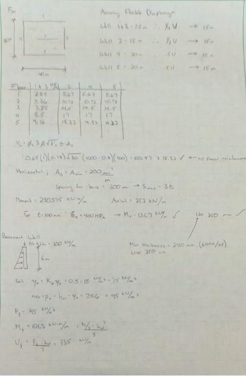
2.3 Seismic Assessment
The parkade structure was analyzed under seismic conditions using the equivalent static force method
according to the BCBC 2018 [2]. Utilizing the seismic information provided in the (NBCC) [3] Appendix C,
the maximum shear force at the base of the structure was found to be 47.5% of the structures weight.
This force was then divided correspondingly to the shear walls on each floor, assuming a non-flexible
diaphragm. This structure was categorized with normal importance and class E soil. See Appendix A for
complete calculations.
2.4 Hydraulic Analysis
A hydrological assessment of potential impacts incurred by the Stadium Neighborhood project was
conducted. The stormwater flows from the 16th Avenue Catchment were assessed using the computer
program EPA SWMM 5.1, as directed in the UBC Technical Guidelines [1]. Due to the increased
development of the Stadium Road Neighborhood, it is expected that the imperviousness of the land will
increase by 15%. The computer program was manipulated to reflect this change of impervious surfaces,
therefore the neighborhood was set to 67% impervious. Stormwater flows and volumes were evaluated
at Junction 26 (JUNC-26) as shown in Figure 2. As all overland stormwater from the upper section of the
catchment travel through this point, the junction was determined to be the most representative of the
area.
9

Figure 2: Junction 26 and 16th Ave Catchment During Peak Flow
The total inflow was evaluated at JUNC-26 during both a 100 year and 10 year storm event. UBC has
committed to following the Leadership in Energy and Environmental Design (LEED) gold standard
guidelines. These standards include regulations that specify detention structures must support the
24-hour storm volume and be discharged at the two-year, pre-development rate [1]. Using the rational
method, the two-year, pre-development rate was determined to be 260 L/s at JUNC-26, therefore the
detention vault will discharge at this rate.
The flow results of the 100 year storm at JUNC-26 can be seen in Figure 3. The peak flow is 650 L/s at
08:30. Since the allowable discharge is 260 L/s as shown by the orange line, the detained volume is
shown by the blue shaded region above the orange line in Figure 3. This area was calculated to be
approximately 3300 m3. Due to the increase in rainfall intensity expected as a result of climate change,
the detention volume was rounded to 3500 m3 . In conclusion, the detention vault was designed with a
10

capacity of 3500 m3 and will discharge at 260 L/s. Further details regarding the design of the detention
vault can be found in Section 4.2.
Figure 3: Total Flow During 100 Year Storm at Junction 26
2.5 Life Cycle Assessment
The parkade will initially have capacity for 130 vehicles and 30 bicycles. The long term vision of the
parkade is to convert parts of the building into community/recreational spaces as the number of
vehicles on site decreases, as per UBC’s vision of the reduction of single-use vehicle trips.
11

3.0 Parkade Structure
3.1 Overview
The parkade structure consists of 4 staggered floors, with 3 floors dedicated to parking and the fourth
consisting of a detention vault. The total dimension of the parkade comes to 95 metres by 30 metres
with a total depth of 7 metres.
3.2 Layout and Traffic Management
The parkade will house 130 parking stalls, 15 of which are dedicated to electric vehicles and 5 dedicated
to handicap. Stall and aisle widths were designed according to [4], prescribing spaces to be 2.5m wide,
one way traffic aisles to be 6m, and 2 way ramps to be 12m. The parking garage was designed in an
attempt to reduce idling and conserve space. This was achieved through having one way traffic, diagonal
stalls and dedicated lanes on W 16th for easy access in and out of the garage. See Appendix E for
complete drawings.
3.3 Loading
The structure is subject to many loading conditions. Being an underground structure with a green roof,
lateral earth pressure loads and a fully saturated green roof load were analyzed along with structure
dead loads and live loads. These loads were established as prescribed in [2].
3.4 Structural System
The structural system consists of slabs, beams and shear walls. These elements were designed for a
consistent size throughout the structure. Slabs will be 300 mm thick and run continuously on top of the
12

beams. The beams will spaced every metre and have dimensions of 250 mm by 800 mm that span 15
metres where they will tie into another beam or wall. Shear walls were designed in order to take these
loads from the beams as well as lateral and seismic forces. These walls will be 300 mm thick. All
components are steel reinforced. See Appendix E for construction drawings and specifications and
Appendix A for detailed calculations.
3.5 Foundation Design
The parkade foundation will be 2 m wide strip footings around the perimeter of the structure, with
depth of 250 mm. For construction ease, the reinforcement placed in the footings will be the same as
the walls. (25M @ 500 mm). See Appendix A for detailed calculations.
3.6 Material Selection
The materials used include cast in place concrete with steel rebar. These materials were selected and
designed in accordance to [5]. All concrete used was considered to be exposed to chlorides despite any
coverings used. A strength of 30 MPa was chosen with a cement, sand, and aggregate ratio of 1:0.75:1.5
[13]. The steel rebar used has dimensions of 55M, 25M, and 25M for beams, slabs, and walls,
respectively.
13

4.0 Hydraulic Substructure
4.1 Overview
The stormwater detention system consists of an integrated detention structure constructed underneath
the second level of the parkade. The structure will capture runoff throughout the West 16th Ave
Catchment and discharge into downstream conveyance structures that will lead to the catchment
outfall. The controlled release of stormwater from the detention structure will reduce erosion
downstream of the site. Of particular importance is the reduction of erosion from the existing
stormwater outfall of the W. 16th Ave Catchment.
4.2 Detention Structure
The detention system is a dry detention vault, as described in Section 4.8 - BMP S7 of the Metro
Vancouver Best Management Practices Guide to Stormwater [6]. The primary purpose of the dry vault is
to control the peak flow. The release rate will be lower than the incoming rate to limit downstream
bankfull flow and erosion of the nearby cliffs. The dry vault will empty completely between storms, and
fill during peak flow times. Through the hydrological analysis completed in the Preliminary Design
Report, the required detention volume of the dry detention vault is 3500 m3. As described in Section 2.4,
the detention vault will discharge at the two-year, pre-development rate which was calculated to be 260
L/s.
It is assumed that water entering the detention vault will be directed from the future drainage system of
the Stadium Neighborhood area and from the existing drainage ditch along W 16th Avenue. The team
assumed that these two stormwater systems would converge near the southeastern corner of the
parkade along W 16th Ave. After the two systems meet, they will flow through an oil grit separator as
14
mentioned in Section 4.3. The oil grit separator will enhance the water quality entering the detention
vault and further infiltration systems. The water will flow through a 450 mm PVC pipe beneath the
entrance of the parkade and will connect to the detention vault underneath the second floor of the
parkade.
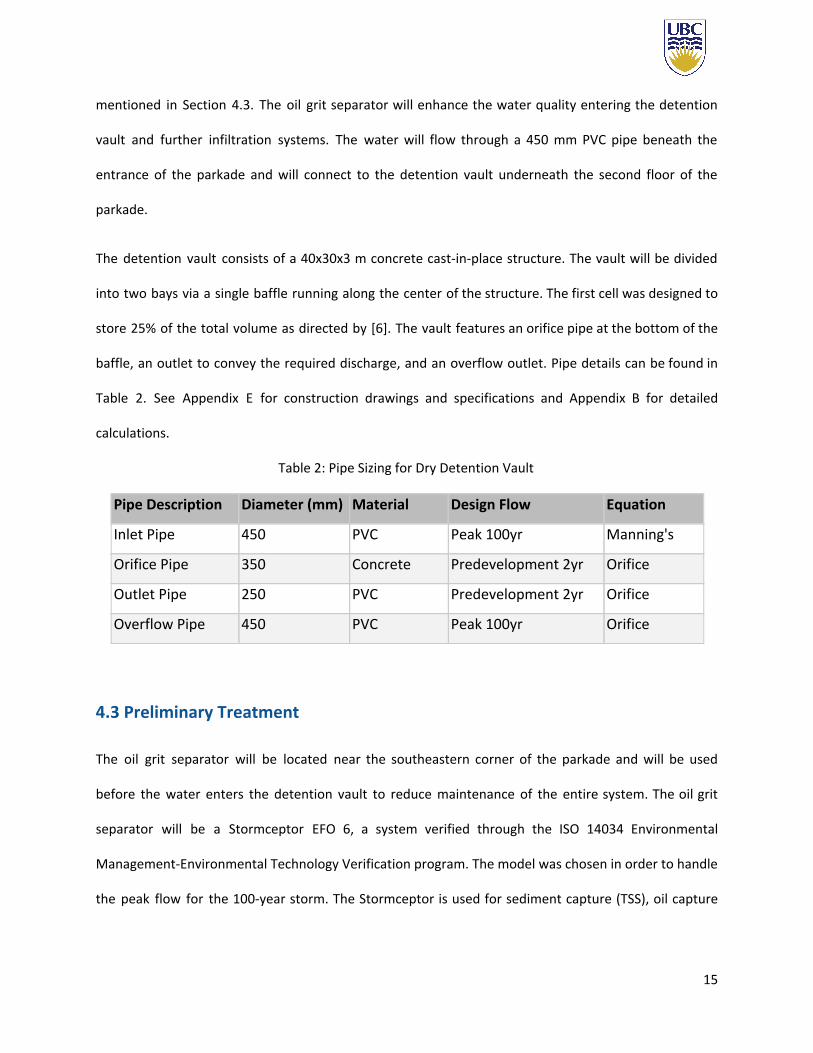
The detention vault consists of a 40x30x3 m concrete cast-in-place structure. The vault will be divided
into two bays via a single baffle running along the center of the structure. The first cell was designed to
store 25% of the total volume as directed by [6]. The vault features an orifice pipe at the bottom of the
baffle, an outlet to convey the required discharge, and an overflow outlet. Pipe details can be found in
Table 2. See Appendix E for construction drawings and specifications and Appendix B for detailed
calculations.
Table 2: Pipe Sizing for Dry Detention Vault
Pipe Description Diameter (mm) Material Design Flow Equation
Inlet Pipe 450 PVC Peak 100yr Manning's
Orifice Pipe 350 Concrete Predevelopment 2yr Orifice
Outlet Pipe 250 PVC Predevelopment 2yr Orifice
Overflow Pipe 450 PVC Peak 100yr Orifice
4.3 Preliminary Treatment
The oil grit separator will be located near the southeastern corner of the parkade and will be used
before the water enters the detention vault to reduce maintenance of the entire system. The oil grit
separator will be a Stormceptor EFO 6, a system verified through the ISO 14034 Environmental
Management-Environmental Technology Verification program. The model was chosen in order to handle
the peak flow for the 100-year storm. The Stormceptor is used for sediment capture (TSS), oil capture
15

and retention, and scour prevention. A diagram of the oil grit separator can be seen in Figure 4. See
Appendix E for drawings and specifications and Appendix B for detailed calculations. The team intends
to purchase a Stormceptor EFO 6 from the Langley Concrete Group, a nearby representative of the
device.
Figure 4: Stormceptor EFO 6 [14]
4.4 Soakaway Pits
The outlet from the dry detention vault is routed to soakaway pits southwest of the parkade. The
soakaway pits were designed according to the guidelines for Soakaway Design by BRE [7], and the Metro
Vancouver Stormwater Source Control Design Guidelines 2012 [8]. The outflow capacity of the soakaway
pit is 22541 m3 in 24 hours, while the design 2 year, 24 hour discharge from the dry detention vault is
22464 m3. The 250 mm outlet PVC pipe coming from the dry detention vault is split into two (2) 150 mm
PVC pipes that lead to twenty-six (26) soakaway pits. The soakaway pits descend 15 m below the 150
16

mm pipe invert, or 16.3 m below grade. Inside the soakaway pits, 100 mm perforated PVC pipe is
surrounded by drain rock at a diameter of 1 m. The pits are spaced at a minimum of 9 m apart, allowing
for adequate infiltration into the surface till and Quadra sand layers described in Section 2.2. The
soakaway pits are designed further than 300 m from the cliffs west of the site [1]. While [13] outlines
the soil conditions in the area of the site, a more detailed analysis of the conditions should be done. Of
particular importance is the behaviour of the till and sand layers when they reach saturation. If the soil
beneath the road is at risk of significant strength reduction under saturated conditions, the installation
of an impermeable barrier may be installed to separate the infiltrating water from road foundation.
Drawings of a plan view of the system and a typical profile of a soakaway pit are provided in Appendix E.
Detailed calculations are shown in Appendix B.
17

5.0 Natural Systems
5.1 Overview
The main purpose of the natural systems are to act as a form of bioretention facility. Bioretention is the
process of collecting, utilizing, and releasing stormwater with a biological medium. For all natural
systems, sod grasses will be used for this purpose. Where applicable, bushes, shrubs, and trees that
won’t negatively impact the existing ecosystem can be used. The three main natural systems proposed
by the team include bioswales, rain gardens, and green roofs.
5.2 Bioswales
The bioswales are designed according to [7]. Bioswales compose of a grassy channel used to collect,
store, and infiltrate stormwater into the ground below. The proposed design involves bioswales with
ponding weirs to run along the outside of the parkade and as well as along W 16th Ave. Currently, water
from the detention structure will be able to collect and discharge a 100-year storm; however, in the
event that the detention structure is at capacity (i.e. a storm greater than 100-years occurs), the
bioswales will help convey stormwater from the detention structure down W 16th Ave. The ponding
weir system will add an additional 96 m3 of stormwater detention that will be slowly infiltrated into the
subsurface. A detailed drawing of the typical design for this project’s bioswales can be found in
Appendix E. See Appendix C for detailed calculations.
18

5.3 Rain Gardens
The bioswales are designed according to [7]. Rain gardens are similar to bioswales as they capture
rainfall, store water in a bioretention medium, and then release the water into the subsurface. The rain
gardens will have full infiltration but may or may not have a reservoir, depending on the geotechnical
and site conditions. Either rain garden scenario will require a growing medium of 450 mm and a two
(horizontal) to one (vertical) slope towards the garden. At locations that have glacial till below the
topsoil, a 5 m deep reservoir with drain rock will be installed in strategic areas. Areas with quadra sand
beneath the topsoil do not require a reservoir since water can infiltrate quicker. See Appendix C for
detailed calculations.
5.4 Green Roofs
The bioswales are designed according to [7]. The top of the parkade will be composed of an intensive
green roof. The roof will have a 600 mm growing medium with a 2% slope towards the drainage piping
that will convey excess rainfall into the detention structure below. The top of the roof will contain
sodded grass and a rock garden that will be aesthetically pleasing for the UBC Stadium Neighbourhood
and will allow the area to be used for community gatherings. The growing medium sizing was based off
Vancouver’s annual average rainfall with a consideration for climate change. This sizing will allow the
roof to capture 54 % of the rainfall that falls directly on the roof. The roof will also provide sound
insulation up to 13 decibels. See Appendix C for detailed calculations.
19

6.0 Construction Plan
6.1 Overview
The construction plan described below is the recommended sequence provided by the team. It is subject
to change on bidding and contractor selection. Lists of tasks and construction considerations, as well as
an overview of the scheduling are provided below. Construction considerations are listed in the
specification sheet in Appendix E. A detailed schedule and work breakdown structure is provided in
Appendix F.
6.2 Tasks
The task list below is a summary list of tasks required during the construction period:
1. Site preparation
1.1. Stripping, grubbing and clearing. Note that tree removal should be done at this stage.
The existing path that runs parallel to W. 16th Ave must be removed.
2. Construction of underground parkade structure
2.1. Installation of excavation support.
2.1.1. Secant pile walls should be used for excavation support for the parkade
structure, as they will be permanent wall supports for the structure.
2.2. Excavation to bulk excavation level of parkade structure
2.2.1. Dewatering should be completed when excavation reaches the perched depths
of perched groundwater as described in Section 5.4. Consideration must be
made for the settlement of W. 16th Ave, when dewatering and excavation are
taking place.
20

2.3. Construction of base level pad and strip foundations
2.4. Construction of shear wall forms, including dry detention wall concrete
2.5. Bottom slab, foundation, and column concrete pours
2.6. Connection of dry detention vault to existing storm system and to discharge locations
2.7. Placement of temporary vertical supports for second floor slab and ramps
2.8. Second floor and ramp form construction
2.9. Second floor and ramp concrete pours
2.10. Placement of temporary vertical supports for grade level slab and ramps
2.11. Grade level floor and ramp form construction
2.12. Grade level floor and ramp concrete pours
3. Above grade building construction
3.1. Roof construction
3.2. Green roof construction
4. Construction of soakaway pits
4.1. Drilling of soakaway pits with casing and perforated pipe placement
4.2. Drain rock placement
4.3. Placement of pipe bedding material
4.4. Pipe connections and cleanouts
4.5. Backfill and covering with base and subbase for pathway paving
4.6. Pathway paving
5. Bioswale Excavation and Installation
21

6.3 Scheduling
The construction will commence May 28th, 2019, and will have a target completion date of
Mid-December. This time frame allows for minimal disruption to class schedules, while most students
are not at the university for summer. This decreases the expected impact on the public via traffic delays.
A full Gantt Chart and task list can be found in Appendix F. It is noted that the construction of the
soakaway pits can commence simultaneously with the construction of the parkade+detention tank
superstructure. The critical path will mainly be the construction timeline of the superstructure, over 180
work-days. Time alloted for inspections is given.
A summary of key project milestones is provided below in Figure 5 below.
Figure 5: Overview of Project Schedule
22
7.0 Operations and Maintenance
7.1 Overview
The operations and maintenance of the system will be separated into three parts: parkade structure,
hydraulic substructure, and natural systems. The recommendations stated in this section are not
limiting, but are meant as a guide. Operations and maintenance will be the responsibility of the owner.
This section of the report will also detail the building safety plan.
7.2 Parkade Structure
The team recommends UBC to retain a consultant experienced in building inspection to perform a
detailed structural inspection every 2 years as per [5]. Our recommendations include inspection of
exposed rebar and concrete spalling, cracking, and chemical degradation. The use of chemical de-icing
compounds should be avoided to minimize structural damage, and additional inspection should be
considered following days where there is heavy usage of de-icing compounds on roadways.
7.3 Hydraulic Substructure
The team recommends maintenance of the dry detention vault that includes yearly inspection and
removal of sediment from the vault interior. This will require a Vac truck whose hose can reach the tank,
or the manual removal of sediment by an operator with a pail and shovel. Additionally, the oil-grit
separator will require maintenance according to the manufacturers specifications. Structural inspections
of the vault should be completed as described in Section 7.2 above. Maintenance of the soakaway pits
includes yearly inspections of the cleanouts at the vertical soakaway pits to ensure that they are not
clogged.
23
7.4 Natural Systems
The main component of each natural system to be maintained will be the vegetation. The bioswales,
rain gardens, and green roofs, will require weekly visual inspections to insure the vegetation is healthy
and growing well. The grass will require to be cut, although the growth rate will vary throughout the
year. During spring months, the grass may need to be cut as often as every 10 days; however, this will
increase during the summer months. The waste from the cutting should be collected and composted.
The growing medium of the vegetation will also require biannual aeration and replanting. Aeration
involves puncturing the growing medium with holes to allow oxygen into the soil. This will help the grass
grow and maintain healthy soil. Aeration should occur during spring and fall, after and before the frost
season. Replanting should occur if any vegetation dies and earth becomes exposed.
7.5 Safety Plan
All construction workers on the project will be properly trained in their expertise. Every morning of
construction will begin with a tailgate safety meeting to go over the required safety checklist. Incidents
will be reported and handled accordingly. All workers will also be required to be well aware of the
emergency response procedure. The proper personal protective equipment (PPE) will be worn at all
times on site during construction. Site specific hazards will be addressed and workers will be well aware
of their safety officer and their contact details.
In addition to the general safe construction practices listed above, the parkade structure will include fire
exits, fire protection, and a specific marshalling area in case of fire. The parkade will also be well lit to
ensure safe access to vehicles and bikes.
24

8.0 Cost
8.1 Overview
A Class A cost estimate was conducted on the Stadium Neighborhood Underground Parkade and Water
Storage Project. An overview of the cost estimate can be seen below in Table 3. The total estimated cost
of the project is $12M and includes pricing of the permitting, general mobilization, parkade structure,
dry detention vault, soakaway pits, and natural systems. Engineering fees, insurance, contingencies, and
GST were added to the original sub-total. The detailed Class A cost estimate can be found in Appendix D.
Table 3: Summary of Class A Cost Estimate
Description Price Permitting $20,000 General $1,100,000 Parkade Structure $5,200,000 Dry Detention Vault $180,000 Soakaway Pits $320,000 Natural Systems $480,000 Sub-total $7,300,000 Engineering & General Contractor Fees (20%) $1,600,000 Insurance and Bonding (2%) $160,000 Contingencies (20%) $1,600,000 GST (5%) $570,000 Estimated Total Cost $12,000,000
25

8.2 Operations and Maintenance
As discussed in Section 7.0, operations and maintenance will be required for all sections constructed.
Together, this will cost approximately $32,000 a year. Of note, operations and maintenance of the
detention structure, soakaway, and invasive plants in the natural systems are highest in cost. The
comprehensive operations and maintenance costs are located in the Class A cost estimate in Appendix
D.
26

9.0 Future Considerations
There are a set of tasks that must be completed as we move from the detailed design phase to the
commencement of construction. This section outlines the future considerations that will be addressed.
The current design is based off of geotechnical assessments of the nearby area. To provide a more
accurate and appropriate design, bore hole testing of the site should be conducted prior to construction
to confirm assumptions. Materials shall be sourced from local suppliers. Specific vegetation and plants
will be suitable for the natural ecosystem at UBC. During construction, material testing will occur on a
regular basis to ensure the required standards are met.
Discussion with UBC Campus and Community planning will continue throughout construction.
Unforeseen changes to design plans and scheduling will be addressed with the use of change orders.
Construction shall be completed to conform with all required safety standards.
As climate change is expected to change rainfall patterns, it is recommended for UBC to record all flow
values throughout the system during the life of the project. Adjustments to the detention vault and
infiltration system shall occur if necessary to reflect climate change impacts.
27

10.0 References
[1] UBC Campus and Community Planning, “Integrated Stormwater Management Plan,” 2017.
[2] British Columbia Building Policy Branch, “British Columbia Building Code 2018”, 2018.
[3] National Research Council Canada, “National Building Code of Canada”, 2015.
[4] City of Vancouver, “Vancouver Parking and Loading Design Supplement”, 2002.
[5] Canadian Structural Association, “S413 Parkade Manual”, 2014.
[6] Metro Vancouver, "Best Management Practices Guide for Stormwater," 1999.
[7] Metro Vancouver, “Stormwater Source Control Design Guidelines 2012,” 2012.
[8] BRE Group, “Soakaway Design”, 1991.
[9] Metro Vancouver, “Climate Projects for Metro Vancouver,” 2016.
[10] Shearwater Designs, “Preliminary Design Report”, 2018.
[11] GeoPacific Consultants Ltd, "Geotechnical Investigation Report for Proposed Mixed
Commercial/Residential Development Lot 10 - UBC South Campus, Westbrook Drive at 16th
Avenue, Vancouver, B.C.," 2006.
[12] Piteau Associates, “Hydrogeological and Geotechnical Assessment of Northwest Area, UBC
Campus,” 2002.
28

[13] “Concrete mix ratio for various grades of concrete - Concrete Mix Design,” Civil Engineering
Blog, 08-Dec-2017. [Online]. Available: http://www.civileblog.com/concrete-mix-ratio/.
[Accessed: 31-Mar-2019].
[14] “Stormceptor EF,” Imbrium Systems. [Online]. Available:
http://www.imbriumsystems.com/stormwater-treatment-solutions/stormceptor-ef#66414-illus
trations. [Accessed: 07-Apr-2019].
[15] UBC Technical Guidelines, “Electrical Underground Ducts and Manholes”, 2018.
[16] UBC Technical Guidelines, “Storm Drainage”, 2018.
29

APPENDIX A: PARKADE STRUCTURE

Concrete Steelphi(c) 0.65 phi(s) 0.85f'c 30 MPa fy 400 MPaalpha 1 0.805 diameter of long. 55 mmbeta 1 0.895 Area of one long. 2500 mm^2
Aggregate Size 20 mmDiameter of Stirrup 10 mmArea of Stirrup 100 mm^2
Parkade Beam SlabLength 40 m b 250 mm Thickness 0.3 mWidth 30 m h 800 mm Length 15 mFloor Clearance Height 2.3 m Length 15 m Trib Width 1 m
Trib width 1 m
Loads Weight Units Trib width Units Trib Height Units Load Units FactoredDead Load Beam Slab 2500.0 kg/m^3 1.0 m 0.3 m 7.4 kN/m 9.2 kN/m
Beam 2500.0 kg/m^3 250.0 mm 800.0 mm 4.9 kN/m 6.1 kN/mSnow Load 1.6 kPa 1.0 1.6 kN/m 0.8 kN/m
Live Load Beam Parkade 2.4 kPa 1.0 m - - 2.4 kN/m 3.6 kN/mGreen Roof 4.8 kPa 1.0 m 4.8 kN/m 7.2 kN/m
Moments Load Area Max Units V UnitsFloor 1 26.9 kN/m 757.9 kN*m 202.1 kNFloor 2 18.9 kN/m 532.4 kN*m 142.0 kNFloor 3 26.9 kN/m 757.9 kN*m 202.1 kNFloor 4 18.9 kN/m 532.4 kN*m 142.0 kN
Tension Steel Design Compression Steel Design Don't Need Shear DesignClear Cover 40.000 mm Number of legs 2.00Number of rows 1.000 dv 657.00d 730.000 mm Beta 0.18As 4024.767 mm^2 Use Vc 105.26 kNa 348.698 mm Shear Reinforcement YesAs(min) 547.723 mm^2 Dont Use Vs 96.85 kNa 348.698 mm Av 200.00 mm^2Mr 760.365 kN*m Okay s 660.00 mm 600) 1.4Number of bars 2.000 1.4*db 1.4*as 30 Vr 202.11 kN OkayS 40.000 mm 77 Okay Okay Vr(max) 800.72 kN Okayrow 0.022 OkayZ
Summary Number per floor Number of Floors Total UnitsConcrete 3 m^3 80 4 960 m^3Steel 2.000 bars 80 4 640 bars 55M, 15m

Concrete Steelphi(c) 0.65 phi(s) 0.85f'c 30 MPa fy 400 MPaalpha 1 0.805 diameter of long. 45 mmbeta 1 0.895 Area of one long. 1500 mm^2
Aggregate Size 20 mmDiameter of Stirrup 10 mmArea of Stirrup 100 mm^2
Parkade Beam SlabLength 40 m b 250 mm Thickness 0.3 mWidth 30 m h 800 mm Length 15 mFloor Clearance Height 2.3 m Length 15 Trib Width 1
Trib width 1
Loads Weight Units Size Units Size Units Load Units FactoredDead Load Beam Slab 2500.0 kg/m^3 1.0 m 0.3 m 7.4 kN/m 9.2 kN/m
Beam 2500.0 kg/m^3 250.0 mm 800.0 mm 4.9 kN/m 6.1 kN/mSnow Load 1.6 kPa 1.0 m 1.6 kN/m 0.8 kN/m
Live Load Beam Parkade 2.4 kPa 1.0 m - - 2.4 kN/m 3.6 kN/mGreen Roof 4.8 kPa 1.0 m 4.8 kN/m 7.2 kN/m
Moments Load Area Max Units V UnitsFloor 1 17.2 kN/m 484.2 kN*m 129.1 kNFloor 2 12.8 kN/m 359.9 kN*m 96.0 kNFloor 3 17.2 kN/m 484.2 kN*m 129.1 kNFloor 4 12.8 kN/m 359.9 kN*m 96.0 kNFloor 5 12.8 kN/m 359.9 kN*m 96.0 kN
One Way Slab Design Shear Design Temperature and ShrinkageNumber of legs 2 Asmin 600 mm^2
d 267.500 dv 240.75 mm S 500 mmAs 7824.745 mm^2 Okay Beta 0.21 A bar 200 mm^2 15MAs(min) 600.000 mm^2 Use Vc 179.9946408 kN s 333.3333333 mm Use 300S 191.700 mm Okay Okay 191.6995267 Shear Reinforcement No As 666.6666667 mm^2a 11.299 mm Vs -50.9 kNMr 696.631 kN*m Okay Av 200 mm
s -461 mm Okay OkayCracking? Vr 129.1 kN Okayfs 240 Vr(max) 4694.625 kN OkayA 5000z 14035.28514
Summary Amount Unit Size Unit Number per floorConcrete 4.5 m^3/m 1 m 15 Number of floors Total UnitsSteel 79 bars 10 m 15 5 337.5 m^3
5 5925 bars 10m of 25M


Basementwalldesign
Propertiesfc 25fy 400phic 0.65phis 0.85
Thicknessh(mm) 9000hu(unsupwallh)mm 6800t(mm) 272 t=hu/25perA23.3Cl.14.1.7.1t(mm) 300
Bending+Shearforces
SoilForceshw(mm) 6800b(mm) 1000Ko 0.5ys(kN/m3) 20yo 10po(Kpa) 68pof(Kpa) 85 basedonloadcombo2(1.25DL+1.5LL)
wf(kPa) 42.5Mf(kN*m/m) 245.65Vf(kN/m) 192.6667
FlexureandAxialt(mm) 272 greaterofhu/25or190mmtactual(mm) 300 fordesignpurposes
VerticalReinforcementdb(mm) 25Cover 20 therefore25M@140mmd(mm) 267.5 perm(7bars)Mr=Mf 245.65As(mm2/m) 3144.495
Areabar 490.8739Reqspacing 156.1058
Spacing(mm) 156.1058 ---> Spacemax3t 900500mm 500
Maxtensioncheckp 0.011755 <pb=.022
MinTensioncheckAg 300000Avmin(mm2/m) 450 <As=1963

LoadsDeadLoads TribWidth(m)TribHeight(m)Load(kN/m)Factored x2floorsSlab(kg/m3) 2500 1 0.3 7.5 9.375 18.75Beam(kg/m3) 2500 0.25 0.8 5 6.25 12.5Wall(kg/m3) 2500 1 9 225 281.25 281.25SnowLoad(kPa) 1.6 1 - 1.6 2 2
314.5
LiveLoads x1floor
Parkade(kPa) 2.4 1 - 2.4 3.6 3.6GreenRoof(kPa) 2.4 1 - 2.4 3.6 3.6
7.2
ShearDesign
Vf(kN/m) 85 =shearduetosoilloadatbottomdv1(mm) 240.75dv2(mm) 216bw(mm) 1000
Beta 0.185372Vc 145.0418 >VfNoHorzShearReinforcementRequired,
DesignforminclausestandardsanywaysAg 300000Ahmin(mm2/m) 600Ab 490.8739s(mm) 156.1058 --> Spacemaxchecks(mm) 156.1058 3t 900MaxTension 0.011755 <pb=.022 500mm 500
therefore25M@500mmperm(2bars)

AxialLoadResistanceA1(mm2) 300000BearingResistance(kN) 4143.75 >DL= 314.5
FactoredAxialResistancelb(horzwalllength)(mm) 2000 A23.3CL.14.1.3.1Ag 600000alpha 0.8phic 0.65
fc 25Ag 600000h 6800t 300Pr(kN) 2590.972 >DL= 314.5
StripFootingDesign(Simplified)BearingLoad(kN) 320b(m) 1qallow(soil)kPa(sandyclay) 150RequiredArea 2.133333WidthFooting(m) 2
Vf(kN/m) 192.6667
h(mm) 250dv(mm) 180Vc 388 >Vf,norebarneededbutstilladdduetocodereq.Usesamereinforcementaswallsfordeisgnease therefore25M@500mm

APPENDIX B: HYDRAULIC SUBSTRUCTURE

Hydraulic Design: Inputs:
Outputs:
Pipe Orifice Pipe Outlet Pipe Overflow Pipe
Q (m3/s) 0.26 0.26 0.65
g (m/s2) 9.81 9.81 9.81
C 0.62 0.62 0.62
h (m) 1.5 3 3
A (m2) 0.077 0.055 0.137
D (m) 0.314 0.264 0.417
V (m/s) 3.363 4.757 4.757
Pipe Inlet Pipe
Q (m3/s) 0.65
n 0.013
Slope (m/m) 0.063
A (m2) 0.148
D (m) 0.435
V (m/2) 4.380
Pipe Description Diameter (mm) Material Design Flow Equation
Inlet Pipe 450 PVC Peak 100yr Manning's
Orifice Pipe 350 Concrete
Predevelopment
2yr Orifice
Outlet Pipe 250 PVC
Predevelopment
2yr Orifice
Overflow Pipe 450 PVC Peak 100yr Orifice

Settling Tank Length Check: Inputs:
Outputs:
Particle diameter
(mm) 0.03
Particle diameter (m) 0.00003
Particle volume
(mm^3) 0
Particle density 1500
Water density 1000
Settling velocity 0.24525
Dynamic Viscosity 0.001
Kinematic Viscosity 0.000001
Reynolds Number 0.0073575
If <2, ok,
else see
below
If Re>2, assume
transition flow
Settling velocity Null
Reynolds number
Settling Distance m) 3
Settling Time (s) 12.2324159
Required Area of Oil-Grit Separator: Inputs:
Outputs:
HR (m^3/s) 0.027
Q (m^3/s) 0.26
A (m^2) 9.62962963
Design of Soakaway Pits: Inputs:
Outputs:
Parameter Value Source/Comment
Inflow, I (m^3) 22464 24 hr, 2 yr outflow from dry detention vault
Infiltration Rate (Till) (m/s) 0.000017
Infiltration Rate (Quadra Sand)
(m/s) 0.00048 Piteau Report
Storm Duration (s) 86400 Metro Van
Depth of Well (m) 16.3
Depth to reach with Auger (1m cover, 150mm pipe,
150mm rock below pipe
Pipe Diameter (m) 0.1
Pit Diameter (m) 0.66 (24" Dual Rotary Drills available locally)
Area (Till ) (m^2) 269.55 Layer approx. 5 m thick below distribtion pipe
Area (Quadra Sand) (m^2) 539.10 Remaining 10 m to final depth
Number of Soakaway Pits 26 Spaced at a minimum of 8m
Outflow (Till) (m^3) 395.91
Outflow (Quadra Sand) (m^3) 22357.44
Outflow Total(m^3) 22753.36
Total Volume of Soakaway Pit
(m^3) 100.51
Volume of individual soakaway
Pit (m^3) 3.87
Volume of Drain Rock per
soakaway pit (m^3) 3.86
Total Volume of Drain Rock 100.25
Storage (m^3) -289.36 Storage = Outflow - Inflow
Difference (m^3) -389.87

APPENDIX C: NATURAL SYSTEMS

Appendix CGreen Roof Calculation
1) Determination of Vancouver's Average Annual Rainfall
YearAnnual Rainfall (mm)
2018 1325.42017 1172.92016 1279.62015 1139.22014 1236.82013 9052012 1161.32011 1045.22010 1190.42009 1055.62008 913.82007 1274.42006 11752005 1183.82004 1200.82003 1086.22002 8182001 1162.32000 979
Average: 1121 mmCC Average: 1177 mm Increase rainfall by 5% to account for climage change by the 2050s
Source: MetroVancouver, "Climate Projections for Metro Vancouver", 20162) Determining the topsoil depth of the green roofThe following figure was retrieved from the Stormwater Source Control Design Guidelines by MetroVancouver
Sorucing from the WeatherStats website the following annual rainfall data was retrieved and used to determine the average annual rainfall.
In order to maximize the annual rainfall capture percentage a topsoil depth of 600
mm was chosen. Using the figure to the left and the annual rainfall, we can
determine that a green roof of 600 mm in Vancouver, will be able to capture
approximately 54% of annual rainfall.

APPENDIX D: COST ESTIMATE

Item No. Description Unit Estimated Quantity Unit Rate Reference Unit
Conversion On-Site Price (USD)
Canadian Conversion
Time Adjustment Price (±15%)
1 Permitting
Stakeholder Engagement Lump Sum 1 1,300 LS $1.00 $1,300.00 $1.00 $1.00 $1,300
Exavation and Backfill Permit Lump Sum 1 2,700 LS $1.00 $2,700.00 $1.00 $1.00 $2,700
Traffic Management Permit Lump Sum 1 600 LS $1.00 $600.00 $1.00 $1.00 $600Street and Landscape Permit Lump Sum 1 500 LS $1.00 $500.00 $1.00 $1.00 $500
Planning Processing Fee Lump Sum 1 5,000 LS $1.00 $5,000.00 $1.00 $1.00 $5,000Development Permit Lump Sum 1 2,400 LS $1.00 $2,400.00 $1.00 $1.00 $2,400Plumbing + Sprinkler + Fire Protection Permits Lump Sum 1 4,000 LS $1.00 $4,000.00 $1.00 $1.00 $4,000
1 Subtotal $20,0002 General
Survey Acre 4 2,000 Acre $1.00 $8,000.00 $1.34 $1.40 $15,008Creation of Break Area/Storage Location m3 1,000 8 m3 $1.00 $8,000.00 $1.00 $1.00 $8,000
Equipment Mobilization Lump Sum 100 305 $1.00 $30,500.00 $1.34 $1.40 $57,218Traffic Control Hr 1750 400 hr $1.00 $700,000.00 $1.00 $1.00 $700,000Temporary Fencing L.M. 1000 7 L.M. $3.28 $24,108.00 $1.34 $1.40 $45,227Tree Removal EA. 50 1,000 EA. $1.00 $50,000.00 $1.00 $1.00 $50,00016th Avenue Concrete Path Removal m2 1,500 13 m2 $1.00 $18,750.00 $1.00 $1.00 $18,750Removal of existing soil base m3 6,000 16 m3 $1.00 $96,000.00 $1.00 $1.00 $96,000Landscaping/Arborist Lump Sum 1 100,000 Lump Sum $1.00 $100,000.00 $1.00 $1.00 $100,000
2 Subtotal $1,100,0003 Parkade Structure
Excavation C.M. 20160 2 C.Y. $1.31 $62,495.19 $1.34 $1.40 $117,241Beam Concrete (Including forms (4 uses), concrete, placement, reinforcing steel, and finishing) C.M. 960 805 C.Y. $1.31 $1,012,368.00 $1.34 $1.40 $1,899,202Slab Concrete (Including forms (4 uses), concrete, placement, reinforcing steel, and finishing) C.M. 337.5 805 C.Y. $1.31 $355,910.63 $1.34 $1.40 $667,688Wall Concrete (Including forms (4 uses), concrete, placement, reinforcing steel, and finishing) C.M. 1176.4 805 C.Y. $1.31 $1,240,572.62 $1.34 $1.40 $2,327,314Electrical Services - Lighting, Heating, Systems Lump Sum 1 25,000 Lump Sum $1.31 $32,750.00 $1.34 $1.40 $61,439Mechanical Services - HVAC, Controls, Plumbing Lump Sum 1 25,000 Lump Sum $1.31 $32,750.00 $1.34 $1.40 $61,439
3 Sub-total $5,200,0004 Dry Detention Vault
Vault Baffle Concrete C.M. 22.5 805 C.Y. $1.31 $23,727.38 $1.34 $1.40 $18,113450mm DR 35 PVC Inlet Pipe L. M. 48 836 L. M. $1.00 $40,128.00 $1.34 $1.22 $65,711450mm DR 35 PVC Overflow Pipe L. M. 5 836 L. M. $1.00 $4,180.00 $1.34 $1.22 $6,845250mm DR 35 PVC Outlet Pipe L. M. 3 210 L. M. $1.00 $629.69 $1.34 $1.22 $1,031Stormceptor EFO 6 Oil Grit Separator Lump Sum 1 75,000 Lump Sum $1.00 $1.00 $1.17 $87,603Concrete Waterproofing C.M. 22.5 8 C.Y. $1.31 $1.34 $1.40 $191
4 Sub-total $180,0005 Soakaway Pits
24" Dual Rotary Drilled holes, 16.3 m deep L.M 423.8 45 L.F $3.28 $62,552.88 $1.34 $1.40 $117,349
Drain Rock C.M. 100.25 42 C.Y. $1.31 $5,515.76 $1.00 $1.00 $5,516
25mm Clean Crush Rock C.M. 30 52 C.Y. $1.31 $2,043.60 $1.00 $1.00 $2,044250mm DR35 PVC Pipe L.M. 3 94 L.F. $3.28 $924.96 $1.34 $1.22 $1,512150mm DR35 PVC Pipe L.M. 400 49 L.F. $3.28 $63,632.00 $1.34 $1.22 $104,200100mm DR28 PVC Perforated PVC Pipe L.M. 416 35 L.F. $3.28 $47,756.80 $1.34 $1.22 $78,073
250mm x 150mm PVC Tee Ea. 1 330 Ea. $1.00 $330.00 $1.00 $1.00 $330150mm PVC Elbow Ea. 2 74 Ea. $1.00 $147.00 $1.00 $1.00 $147
150mm x 100mm PVC Tee Ea. 26 110 Ea. $1.00 $2,860.00 $1.00 $1.00 $2,8605 Sub-total $320,0006 Natural Systems
Bioswales C.M. 3000 10 C.Y. $1.31 $39,240.00 $1.34 $1.40 $73,614Rain Gardens Lump Sum 1 100,000 LS $1.00 $100,000.00 $1.00 $1.00 $100,000Green Roof Lump Sum 1 100,000 LS $1.00 $100,000.00 $1.00 $1.00 $100,000Landscaping/Arborist Lump Sum 2 100,000 LS $1.00 $200,000.00 $1.00 $1.00 $200,000
6 Sub-total $480,0007 Sub-total for All Tasks $8,000,000
8Engineering & General Contractor Fees (20%) $1,600,000
9 Insurance and Bonding (2%) $160,00010 Contingencies (20%) $1,600,00011 Sub-total Construction + Engineering $11,400,00012 GST (5%) $570,00013 Estimated Total Cost $12,000,000

Maintenance & OperationsParkade Inspection per year 12 200 per year $1.00 $2,400.00 $1.00 $1.00 $2,400Parkade Cleaning per year 48 150 per year $1.00 $7,200.00 $1.00 $1.00 $7,200Detention Structure Calibration per year 6 600 per year $1.00 $3,600.00 $1.00 $1.00 $3,600Detention Structure Inspections per year 6 800 per year $1.00 $4,800.00 $1.00 $1.00 $4,800Detention Structure Additional Inspections after large rainfall per year 1 1,600 per year $1.00 $1,600.00 $1.00 $1.00 $1,600Soakaway Inspections per year 6 600 per year $1.00 $3,600.00 $1.00 $1.00 $3,600Soakaway Additional Inspections after large rainfall per year 6 800 per year $1.00 $4,800.00 $1.00 $1.00 $4,800Natural Systems Grass Cutting per year 5 500 per year $1.00 $2,500.00 $1.00 $1.00 $2,500Natural Systems Invasive Plant Maintenance per year 2 600 per year $1.00 $1,200.00 $1.00 $1.00 $1,200Maintenance & Operations Sub-total $32,000

APPENDIX E: DRAWINGS

Soakaway (MetroVancouver, Stormwater Source Control Design Guidelines 2012 [7])
1. Materials:1.1. Infiltration Drain Rock: Clean round stone or crushed rock, with porosity of 35 to 40% such as 75mm max, 38mm min (Maryland Dept. Environmental Resource Programs, 2001)1.2. Pipe: PVC, DR 35 100mm min Diameter with cleanouts certified to CSA B182.1 as per MMCD1.3. Perforated Pipe: PVC, DR 28 100mm min Diameter.1.4. Geosynthetics: as per Section 31-32-19, select for filter criteria or from approved local government product list
2. Construction Practices:2.1. Isolate the infiltration site from sedimentation during construction, either by use of effective erosion and sediment control measures upstream, or by delaying excavation of 300mm of material over the final
subgrade until after all sediment-producing construction in the drainage area has been completed. (Maryland Dept. Environmental Resource Programs, 2001)2.2. Prevent natural or fill soils from intermixing with the infiltration Drain Rock. All contaminated stone aggregate must be removed and replaced. (Maryland Dept. Environmental Resource Programs, 2001)2.3. Infiltration Drain Rock shall be installed in 300mm lifts and compacted to eliminate voids between the geotextile and surrounding soils. (Maryland Dept. Environmental Resource Programs, 2001)2.4. Provide a min. of 150mm of 25 mm or 19 mm clean crushed rock under all pipes2.5. Pipe cover below the ground surface be greater than 1.0 m.2.6. Ensure effective erosion control practices are in place during the construction period. If fine sediments are deposited on infiltration areas by accident, remove the surface crust prior to opening the infiltration
facility.2.7. If possible, have stormwater outfalls bypass the proposed infiltration area during construction.2.8. Do not place erosion control sediment traps in infiltration areas.2.9. Ensure that bottom and sides of excavations are scarified to remove glazing and improve infiltration2.10. Avoid the intrusion of road sands and construction traffic sediments into infiltration facilities.
Dry Detention Vault (MetroVancouver, Best Management Practices Guide for Stormwater, S7: Dry Detention Vault and Wet Vault [6])
1. Design Features:1.1. The dry detention vault will be divided into 2 cells using a baffle. The first cell will occupy 25% of the total detained volume (WSDOE, 1992)1.2. Access via manholes are required1.3. The location will ensure ease of access by maintenance vehicles1.4. The location will be at least 15 m from steep slopes1.5. The vault will empty between storms
2. Materials:2.1. Inflow pipe: PVC Class SDR 35, 450 mm minimum diam. to convey 100 year peak flow2.2. Orifice pipe: Concrete, 350 mm diam.2.3. Outlet pipe: PVC Class SDR 35, 250 mm minimum diam. to discharge the two-year, pre-development flow rate2.4. Overflow pipe: PVC Class SDR 35, 450 mm minimum diam. to convey 100 year peak flow2.5. Vault: Cast-in-place, reinforced concrete2.6. Baffles: Cast-in-place, reinforced concrete
Manholes: (UBC Technical Guidelines, Electrical Underground Ducts and Manholes 2018 [15])1. Manholes shall have inside dimensions of 1830 mm x 3300 mm x 2000 mm high2. The manholes must include cast manhole cover, frame, and brick assembly between manhole and lid3. Materials include: pre-cast manhole assembly, manhole frame, cover, spacer rings, pulling irons, ground rods, sump cover4. Concrete will not be placed in foundations until soil has been reviewed by the Engineer5. The sump must have positive drainage and will be connected to the storm water system6. Operation and Maintenance Requirements:7. Confined entry procedures will be followed when entering the vault8. The vault will be inspected annually to remove floating debris and oil9. Sediments will be removed from the vault when the depth reaches 150 mm10. Maintenance plan is required and will be written prior to construction
..\..\..\Pictures\shearwater.jpgSTADIUM NEIGHBOUHOOD SWM Shearwater Engineering2335 Engineering Road
General Notes
C 000
NTS
31/03/19
0DLJD
PR
OD
UC
ED
BY
AN
AU
TO
DE
SK
ST
UD
EN
T V
ER
SIO
NPRODUCED BY AN AUTODESK STUDENT VERSION
PR
OD
UC
ED
BY
AN
AU
TO
DE
SK
ST
UD
EN
T V
ER
SIO
NPRODUCED BY AN AUTODESK STUDENT VERSION

General Storm Drainage (UBC Technical Guidelines, Storm Drainage 2018 [16])
1. Materials:1.1. PVC Class SDR 28 (150 mm diam. And smaller) and SDR 351.2. Concrete reinforced C76 required for all pipes 600 mm in diameter and larger1.3. Corrugated HDPE with minimum pipe stiffness of 320 kPa1.4. PVC piping preferred for all diam. 300 mm or smaller
2. Design:2.1. Rational method shall be used for design of drainage systems of 10 hectares or less. The hydrograph method should be used for catchments exceeding this area2.2. All hydrograph modeling shall be completed with a SWMM based program2.3. Storm water shall flow only by gravity into the system2.4. All storm sewer piping will be designed to have a minimum velocity of 0.6 m/s when flowing full or half full, based on Manning’s formula. Velocity exceeding 3 m/s will undergo structural stability and durability
assessments
Parking Structure (CSA S413-14 Parkade Manual [5])1. Materials:
1.1. Concrete materials will be in accordance with CSA A23.11.2. Floors and roofs made of concrete and subjected to traffic will be considered exposed to chlorides1.3. Coarse aggregate abrasion loss shall be limited to a maximum of 35%1.4. Sealants will take into account exposure, temperature, traffic, and movement
2. Construction:2.1. Elevations of forms will be verified before concrete placement to ensure proper drainage slopes2.2. De-icing chemicals are corrosive and should not be used on the formwork2.3. Slab surfaces shall not be overworked to avoid scaling2.4. Measures shall be taken to avoid evaporation during curing2.5. The concrete shall be covered in blankets in cold weather2.6. Forms shall only be removed when the concrete is at least 75% of the specified 28 day strength2.7. Waterproofing membrane systems may only be installed when the substrate temperature is at least 2 degrees above the dew point2.8. Work on the site will be inspected and tested to comply with these specifications and CSA S413-14.
STADIUM NEIGHBOUHOOD SWM Shearwater Engineering2335 Engineering Road
C 000
NTS
31/03/19
0DLJDGeneral Notes
..\..\..\Pictures\shearwater.jpg
PR
OD
UC
ED
BY
AN
AU
TO
DE
SK
ST
UD
EN
T V
ER
SIO
NPRODUCED BY AN AUTODESK STUDENT VERSION
PR
OD
UC
ED
BY
AN
AU
TO
DE
SK
ST
UD
EN
T V
ER
SIO
NPRODUCED BY AN AUTODESK STUDENT VERSION

W 16th AV
Bike Storage
AA30
402.5
6
N
..\..\..\Pictures\shearwater.jpgSTADIUM NEIGHBOUHOOD SWM Shearwater Engineering2335 Engineering Road
Parkade Cross-Section AA
C 001
NTS
31/03/19
2DLJD
PR
OD
UC
ED
BY
AN
AU
TO
DE
SK
ST
UD
EN
T V
ER
SIO
NPRODUCED BY AN AUTODESK STUDENT VERSION
PR
OD
UC
ED
BY
AN
AU
TO
DE
SK
ST
UD
EN
T V
ER
SIO
NPRODUCED BY AN AUTODESK STUDENT VERSION

Stormwater DetentionTank
N
..\..\..\Pictures\shearwater.jpgSTADIUM NEIGHBOUHOOD SWM Shearwater Engineering2335 Engineering Road
Parkade Cross-Section AA
C 002
NTS
31/03/19
0DLJD
PR
OD
UC
ED
BY
AN
AU
TO
DE
SK
ST
UD
EN
T V
ER
SIO
NPRODUCED BY AN AUTODESK STUDENT VERSION
PR
OD
UC
ED
BY
AN
AU
TO
DE
SK
ST
UD
EN
T V
ER
SIO
NPRODUCED BY AN AUTODESK STUDENT VERSION

Bike Storage
Detention Vault
Parking Level 2
Parking Level 3
Parking Level 1Entrance/Exit
Green Roof Green Roofand Path to StadiumNeighbourhood
AA
N
..\..\..\Pictures\shearwater.jpgSTADIUM NEIGHBOUHOOD SWM Shearwater Engineering2335 Engineering Road
Parkade Cross-Section AA
C 003
NTS
31/03/19
2DLJD
PR
OD
UC
ED
BY
AN
AU
TO
DE
SK
ST
UD
EN
T V
ER
SIO
NPRODUCED BY AN AUTODESK STUDENT VERSION
PR
OD
UC
ED
BY
AN
AU
TO
DE
SK
ST
UD
EN
T V
ER
SIO
NPRODUCED BY AN AUTODESK STUDENT VERSION

GREEN ROOF
A A
0.50.5 0.5 0.5
MAPEPLAN TB15 ROOT RESISTANT
WATERPROOF MEMBRANE
ROOF PERIMETER BARRIER
GROWING MEDIUM
0.6
ROOF PENETRATION BARRIER
SOD
15.8 15.8
ROOF DRAIN TO
DETENTION VAULT
STADIUM NEIGHBOUHOOD SWM
GREEN ROOF
C 004
1:500
03/04/2019
0
N
Shearwater Engineering2335 Engineering Road
DL DL
GREENROOF SECTION A-A
SCALE: 1:50
PR
OD
UC
ED
B
Y A
N A
UT
OD
ES
K S
TU
DE
NT
V
ER
SIO
N
PRODUCED BY AN AUTODESK STUDENT VERSION
PR
OD
UC
ED
B
Y A
N A
UT
OD
ES
K S
TU
DE
NT
V
ER
SIO
N
PRODUCED BY AN AUTODESK STUDENT VERSION
9
17
FROM 100mmx150mm DR35 PVC TEE:
WESTWARD CONSTRUCTION:
250mm DR35 PVC PIPE TO DETENTION TANK
NORTH/SOUHWARD CONSTRUCTION:
4m 150mm DR35 PVC PIPE
90° 150mm DR35 PVC BEND TO EAST
CUT TO SUIT 150mm DR35 PVC
13 x SOAKAWAY PIT 17m SPACING - SEE DETAIL
TOPSOIL
1
40mmØ DRAINAGE ROCK
0.66
15
FROM 100mmx150mm PVC CROSS
UPWARDS CONSTRUCTION:
0.9m DR28 100mm PVC PIPE
100mm CLEANOUT
DOWNWARDS CONSTRUCTION:
15m DR28 100mm PERFORATED PIPE
5m
GLACIAL TILL
10m
QUADRA SAND
STADIUM NEIGHBOUHOOD SWM
SOAKAWAY PIT
C 005
1:500
01/04/19
2
MA
TC
HLIN
E
SE
E S
HE
ET
C
005
MA
TC
HLIN
E
SE
E S
HE
ET
C
005
SOAKAWAY PIT DETAIL
SCALE: 1:50
Shearwater Engineering2335 Engineering Road
DL DL
PR
OD
UC
ED
B
Y A
N A
UT
OD
ES
K S
TU
DE
NT
V
ER
SIO
N
PRODUCED BY AN AUTODESK STUDENT VERSION
PR
OD
UC
ED
B
Y A
N A
UT
OD
ES
K S
TU
DE
NT
V
ER
SIO
N
PRODUCED BY AN AUTODESK STUDENT VERSION

5%
5%
10
10
4.2
3
1
0.6
EX. SCARIFIED SUBSOIL
GROWING MEDIUM
0.2M CONCRETE WEIR
0.3
SOD
0.2
0.2
IMPERMEABLE CLAY CURTAIN
CONCRETE WEIR
0.3
GROWING MEDIUM
EX. SCARIFIED SUBSOIL
WATER POND
EROSION PROTECTION GRAVEL
3:1 3:1
5%
5%
EROSION PROTECTION GRAVEL
SOD
CONCRETE WEIR
STADIUM NEIGHBOUHOOD SWM
BIOSWALE
C 006
1:50
01/04/19
0
BIOSWALE SECTION DETAIL
SCALE: 1:50
PONDING WEIR DETAIL
SCALE: 1:50
BIOSWALE PLAN VIEW
SCALE: 1:50
BIOSWALE SECTION VIEW
SCALE: 1:50
Shearwater Engineering2335 Engineering Road
DL DL
PR
OD
UC
ED
B
Y A
N A
UT
OD
ES
K S
TU
DE
NT
V
ER
SIO
N
PRODUCED BY AN AUTODESK STUDENT VERSION
PR
OD
UC
ED
B
Y A
N A
UT
OD
ES
K S
TU
DE
NT
V
ER
SIO
N
PRODUCED BY AN AUTODESK STUDENT VERSION

30.
0
20.0 20.0
0.4
5
0.4
50
.25
Manhole Manhole
Weir
Inlet Pipe
Outlet Pipe
Overflow Pipe
Orifice Pipe
N
..\..\..\Pictures\shearwater.jpgSTADIUM NEIGHBOUHOOD SWM Shearwater Engineering2335 Engineering Road
Parkade Cross-Section AA
C 007
NTS
31/03/19
0DLJD
PR
OD
UC
ED
BY
AN
AU
TO
DE
SK
ST
UD
EN
T V
ER
SIO
NPRODUCED BY AN AUTODESK STUDENT VERSION
PR
OD
UC
ED
BY
AN
AU
TO
DE
SK
ST
UD
EN
T V
ER
SIO
NPRODUCED BY AN AUTODESK STUDENT VERSION

0.1
1.5
Manhole Manhole
0.4
5
0.3
53.0
40.0
0.2
5
Overflow Structure
Inlet Pipe
Orifice Pipe
Standard Ladder
Standard Ladder
N
..\..\..\Pictures\shearwater.jpgSTADIUM NEIGHBOUHOOD SWM Shearwater Engineering2335 Engineering Road
Parkade Cross-Section AA
C 008
NTS
31/03/19
0DLJD
PR
OD
UC
ED
BY
AN
AU
TO
DE
SK
ST
UD
EN
T V
ER
SIO
NPRODUCED BY AN AUTODESK STUDENT VERSION
PR
OD
UC
ED
BY
AN
AU
TO
DE
SK
ST
UD
EN
T V
ER
SIO
NPRODUCED BY AN AUTODESK STUDENT VERSION

A1
A1
A2A2
40
30
A1
A1
A2A2
1m O.C.
40
15
15
12
A3
A4
x2
A4
x2
A5
63
6
Beam Schedule
Beam Type
A1
A2
A3
A4
A5
Depth x Width Length Rebar
0.8 x 0.25 15
12.5
10
12
6
Tension: 1 row of 2 55M bars
Shear: 2 legs of 10M Stirrups at 600 mm0.8 x 0.25
0.8 x 0.25
0.8 x 0.25
0.8 x 0.25
Tension: 1 row of 2 55M bars
Tension: 1 row of 2 55M bars
Tension: 1 row of 2 55M bars
Tension: 1 row of 2 55M bars
Shear: 2 legs of 10M Stirrups at 600 mm
Shear: 2 legs of 10M Stirrups at 600 mm
Shear: 2 legs of 10M Stirrups at 600 mm
Shear: 2 legs of 10M Stirrups at 600 mm
N
..\..\..\Pictures\shearwater.jpgSTADIUM NEIGHBOUHOOD SWM Shearwater Engineering2335 Engineering Road
Parkade Cross-Section AA
C 009
NTS
31/03/19
0DLJD
PR
OD
UC
ED
BY
AN
AU
TO
DE
SK
ST
UD
EN
T V
ER
SIO
NPRODUCED BY AN AUTODESK STUDENT VERSION
PR
OD
UC
ED
BY
AN
AU
TO
DE
SK
ST
UD
EN
T V
ER
SIO
NPRODUCED BY AN AUTODESK STUDENT VERSION

2-55M
10M@ 600
0,25
0,8
1.0
0,3
A. Beam Cross-Section
B. Slab Cross-Section
0,0
4
45M@ 20015M@ 300
0,0
4
..\..\..\Pictures\shearwater.jpgSTADIUM NEIGHBOUHOOD SWM Shearwater Engineering2335 Engineering Road
Parkade Cross-Section AA
C 010
NTS
31/03/19
0DLJD
PR
OD
UC
ED
BY
AN
AU
TO
DE
SK
ST
UD
EN
T V
ER
SIO
NPRODUCED BY AN AUTODESK STUDENT VERSION
PR
OD
UC
ED
BY
AN
AU
TO
DE
SK
ST
UD
EN
T V
ER
SIO
NPRODUCED BY AN AUTODESK STUDENT VERSION
25M@ 500
25M@ 500
25M@ 500
25M@ 140
0,2
5
2.0
0,3
0,075
0,0
75
..\..\..\Pictures\shearwater.jpgSTADIUM NEIGHBOUHOOD SWM Shearwater Engineering2335 Engineering Road
Parkade Cross-Section AA
C 011
NTS
31/03/19
0DLJD
PR
OD
UC
ED
BY
AN
AU
TO
DE
SK
ST
UD
EN
T V
ER
SIO
NPRODUCED BY AN AUTODESK STUDENT VERSION
PR
OD
UC
ED
BY
AN
AU
TO
DE
SK
ST
UD
EN
T V
ER
SIO
NPRODUCED BY AN AUTODESK STUDENT VERSION

005
/26/
17IN
ITIA
L R
ELEA
SEJS
K
16/
8/18
OUT
LET
PLAT
FOR
MJS
K
####
####
####
####
####
####
####
####
####
####
####
####
SCAL
E =
NTS
DATE:
APPROVED:CHECKED:
SHEET:OF
DRAWN:DESIGNED:
1
SEQUENCE No.:PROJECT No.:
1
JSK
SP
*EFO6
BSF
JSK
10/13/2017
INSTALLATION NOTESA. ANY SUB-BASE, BACKFILL DEPTH, AND/OR ANTI-FLOTATION PROVISIONS ARE
SITE-SPECIFIC DESIGN CONSIDERATIONS AND SHALL BE SPECIFIED BYENGINEER OF RECORD.
B. CONTRACTOR TO PROVIDE EQUIPMENT WITH SUFFICIENT LIFTING AND REACHCAPACITY TO LIFT AND SET THE STRUCTURE (LIFTING CLUTCHES PROVIDED)
C. CONTRACTOR WILL INSTALL AND LEVEL THE STRUCTURE, SEALING THE JOINTS,LINE ENTRY AND EXIT POINTS (NON-SHRINK GROUT WITH APPROVEDWATERSTOP OR FLEXIBLE BOOT)
D. CONTRACTOR TO TAKE APPROPRIATE MEASURES TO PROTECT THE DEVICEFROM CONSTRUCTION-RELATED EROSION RUNOFF.
E. DEVICE ACTIVATION, BY CONTRACTOR, SHALL OCCUR ONLY AFTER SITE HASBEEN STABILIZED AND THE STORMCEPTOR UNIT IS CLEAN AND FREE OFDEBRIS.
FOR SITE SPECIFIC DRAWINGS PLEASE CONTACT YOUR LOCAL STORMCEPTOR REPRESENTATIVE.SITE SPECIFIC DRAWINGS ARE BASED ON THE BEST AVAILABLE INFORMATION AT THE TIME. SOMEFIELD REVISIONS TO THE SYSTEM LOCATION OR CONNECTION PIPING MAY BE NECESSARY BASEDON AVAILABLE SPACE OR SITE CONFIGURATION REVISIONS. ELEVATIONS SHOULD BE MAINTAINEDEXCEPT WHERE NOTED ON BYPASS STRUCTURE (IF REQUIRED).
STANDARD DETAILNOT FOR CONSTRUCTION
STRUCTURE ID
WATER QUALITY FLOW RATE (L/s)PEAK FLOW RATE (L/s)RETURN PERIOD OF PEAK FLOW (yrs)DRAINAGE AREA (HA)
PIPE DATA: I.E. MAT'L DIAINLET #1INLET #2OUTLET
SITE SPECIFIC DATA REQUIREMENTS
DRAINAGE AREA IMPERVIOUSNESS (%)
* PER ENGINEER OF RECORD
SLOPE % HGL
STORMCEPTOR MODEL
****
***
***
***
**
EFO6
*
***
*
*
DRAWING NOT TO BE USED FOR CONSTRUCTION
GENERAL NOTES:* MAXIMUM SURFACE LOADING RATE (SLR) INTO LOWER CHAMBER THROUGH
DROP PIPE IS 1135 L/min/m2 (27.9 gpm/ft2) FOR STORMCEPTOR EF6 AND 535L/min/m2 (13.1 gpm/ft2) FOR STORMCEPTOR EFO6 (OIL CAPTURECONFIGURATION).
1. ALL DIMENSIONS INDICATED ARE IN MILLIMETERS (INCHES) UNLESSOTHERWISE SPECIFIED.
2. STORMCEPTOR STRUCTURE INLET AND OUTLET PIPE SIZE AND ORIENTATIONSHOWN FOR INFORMATIONAL PURPOSES ONLY.
3. UNLESS OTHERWISE NOTED, BYPASS INFRASTRUCTURE, SUCH AS ALLUPSTREAM DIVERSION STRUCTURES, CONNECTING STRUCTURES, OR PIPECONDUITS CONNECTING TO COMPLETE THE STORMCEPTOR SYSTEM SHALL BEPROVIDED AND ADDRESSED SEPARATELY.
4. DRAWING FOR INFORMATION PURPOSES ONLY. REFER TO ENGINEER'SSITE/UTILITY PLAN FOR STRUCTURE ORIENTATION.
5. NO PRODUCT SUBSTITUTIONS SHALL BE ACCEPTED UNLESS SUBMITTED 10DAYS PRIOR TO PROJECT BID DATE, OR AS DIRECTED BY THE ENGINEER OFRECORD.
HYDROCARBON STORAGE REQ'D (L) *

OGS Specification – Light Liquid Re-Entrainment Simulation Tested and Verified Page 1 of 8
STANDARD SPECIFICATION FOR “OIL GRIT SEPARATOR” (OGS) STORMWATER QUALITY TREAMENT DEVICE WITH THIRD-PARTY VERIFIED LIGHT LIQUID RE-ENTRAINMENT SIMULATION
PERFORMANCE TESTING RESULTS PART 1 – GENERAL 1.1 WORK INCLUDED This section specifies requirements for selecting, sizing, designing, maintaining, and constructing an underground Oil Grit Separator (OGS) device for stormwater quality treatment, specifically an OGS device that has been third-party tested for oil and fuel retention capability using a protocol for light liquid re-entrainment simulation testing, with t testing results and a Statement of Verification in accordance with all the provisions of ISO 14034 Environmental Management – Environmental Technology Verification (ETV). Work includes supply and installation of concrete bases, precast sections, and the appropriate precast section with OGS internal components correctly installed within the system, watertight sealed to the precast concrete prior to arrival to the project site.
1.2 REFERENCE STANDARDS
1.2.1 For Canadian projects only, the following reference standards apply:
CAN/CSA-A257.4-14: Joints for Circular Concrete Sewer and Culvert Pipe, Manhole Sections, and Fittings Using Rubber Gaskets CAN/CSA-A257.4-14: Precast Reinforced Circular Concrete Manhole Sections, Catch Basins, and Fittings CAN/CSA-S6-00: Canadian Highway Bridge Design Code 1.2.2 For ALL projects, the following reference standards apply:
ASTM D-4097: Contact Molded Glass Fiber Reinforced Chemical Resistant Tanks ASTM C 478: Specification for Precast Reinforced Concrete Manhole Sections ASTM C 443: Specification for Joints for Concrete Pipe and Manholes, Using Rubber Gaskets ASTM C 891: Standard Practice for Installation of Underground Precast Concrete Utility
Structures ASTM D2563: Standard Practice for Classification of Visual Defects in Reinforced Plastics
1.3 SHOP DRAWINGS
1.3.1 Shop drawings shall be submitted upon request with each order to the contractor then forwarded to the Engineer of Record for review and acceptance. Shop drawings shall detail the precast concrete components and OGS internal components prior to shipment, including the sequence for installation. 1.3.2 Unless directed otherwise by the Engineer of Record, OGS stormwater quality treatment product substitutions or alternatives submitted within ten days prior to project bid shall not be accepted. All alternatives or substitutions submitted shall be based on the exact same criteria detailed in Section 3, in entirety, subject to review and approval by the Engineer of Record. Any and all changes to project cost estimates, bonding amounts, plan check fees for revision of approved documents, or design impacts due to regulatory requirements as a result of a product substitution shall be coordinated by the Contractor with the Engineer of Record.
1.4 HANDLING AND STORAGE
Prevent damage to materials during storage and handling.

OGS Specification – Light Liquid Re-Entrainment Simulation Tested and Verified Page 2 of 8
1.4.1 OGS internal components supplied by the Manufacturer for attachment to the precast concrete vessel shall be pre-fabricated, bolted to the precast and watertight sealed to the precast vessel surface prior to site delivery to ensure Manufacturer’s internal assembly process and quality control processes are fully adhered to, and to prevent materials damage on site. 1.4.2 Follow all instructions including the sequence for installation in the shop drawings during installation.
PART 2 – PRODUCTS 2.1 GENERAL
2.1.1 The OGS vessel shall be cylindrical and constructed from precast concrete riser and slab components.
2.1.2 The precast concrete OGS internal components shall include a fiberglass insert bolted and watertight sealed inside the precast concrete vessel, prior to site delivery. Primary internal components that are to be anchored and watertight sealed to the precast concrete vessel shall be done so only by the Manufacturer prior to arrival at the job site to ensure product quality.
2.1.3 The OGS shall be allowed to be specified and have the ability to function as a 240-degree bend structure in the stormwater drainage system, or as a junction structure. 2.1.4 The OGS to be specified shall have the capability to accept influent flow from an inlet grate and an inlet pipe.
2.2 PRECAST CONCRETE SECTIONS All precast concrete components shall be designed and manufactured to meet highway loading conditions per State/Provincial or local requirements. 2.3 GASKETS Only profile neoprene or nitrile rubber gaskets that are oil resistant shall be accepted. For Canadian projects only, gaskets shall be in accordance to CSA A257.4-14. Mastic sealants, butyl tape/rope or Conseal CS-101 alone are not acceptable gasket materials. 2.4 JOINTS The concrete joints shall be watertight and meet the design criteria according to ASTM C-990. For projects where joints require gaskets, the concrete joints shall be watertight and oil resistant and meet the design criteria according to ASTM C-443. Mastic sealants or butyl tape/rope alone are not an acceptable alternative. 2.5 FRAMES AND COVERS Frames and covers shall be manufactured in accordance with State/Provincial or local requirements for inspection and maintenance access purposes. A minimum of one cover, at least 22-inch (560 mm) in diameter, shall be clearly embossed with the OGS manufacturer’s product name to properly identify this asset’s purpose is for stormwater quality treatment. 2.6 PRECAST CONCRETE All precast concrete components shall conform to the appropriate CSA or ASTM specifications. 2.7 FIBERGLASS
OGS Specification – Light Liquid Re-Entrainment Simulation Tested and Verified Page 3 of 8
The fiberglass portion of the OGS device shall be constructed in accordance with ASTM D2563, and in accordance with the PS15-69 manufacturing standard, and shall only be installed, bolted and watertight sealed to the precast concrete by the Manufacturer prior to arrival at the project site to ensure product quality. 2.8 OGS POLLUTANT STORAGE The OGS device shall include a sump for sediment storage, and a fiberglass insert for the capture and storage of petroleum hydrocarbons and buoyant gross pollutants. The total sediment storage capacity shall be a minimum 40 ft3 (1.1 m3). The total petroleum hydrocarbon storage capacity shall be a minimum 50 gallons (189 liters). The access opening to the sump of the OGS device for periodic inspection and maintenance purposes shall be a minimum 16 inches (406 mm) in diameter. 2.9 LADDERS Ladder rungs shall be provided upon request or to comply with State/Provincial or local requirements. 2.10 INSPECTION All precast concrete sections shall be level and inspected to ensure dimensions, appearance, integrity of internal components, and quality of the product meets State/Provincial or local specifications and associated standards. PART 3 – PERFORMANCE & DESIGN 3.1 GENERAL The OGS stormwater quality treatment device shall be verified in accordance with ISO 14034:2016 Environmental management – Environmental technology verification (ETV). The OGS stormwater quality treatment device shall remove oil, sediment and gross pollutants from stormwater runoff during frequent wet weather events, and retain these pollutants during less frequent high flow wet weather events below the insert within the OGS for later removal during maintenance. The Manufacturer shall have at least ten (10) years of local experience, history and success in engineering design, manufacturing and production and supply of OGS stormwater quality treatment device systems, acceptable to the Engineer of Record. 3.2 HYDROLOGY AND RUNOFF VOLUME The OGS device shall be engineered, designed and sized to treat a minimum of 90 percent of the average annual runoff volume, unless otherwise stated by the Engineer of Record, using historical rainfall data. Rainfall data sets should be comprised of a minimum 15-years of rainfall data or a longer continuous period if available for a given location, but in all cases a minimum 5-year period of rainfall data. 3.3 ANNUAL (TSS) SEDIMIMENT LOAD AND STORAGE CAPACITY The OGS device shall be capable of removing and have sufficient storage capacity for the calculated annual total suspended solids (TSS) mass load and volume without scouring previously captured pollutants prior to maintenance being required. The annual (TSS) sediment load and volume transported from the drainage area should be calculated and compared to the OGS device’s available storage capacity by the specifying Engineer to ensure adequate capacity between maintenance cycles. Sediment loadings shall be determined by land use and defined as a minimum of 450 kg (992 lb) of sediment (TSS) per impervious hectare of drainage area per year, or greater based on land use, as noted in Table 1 below. Annual sediment volume calculations shall be performed using the projected average annual treated runoff volume, a typical sediment bulk density of 1602 kg/m3 (100 lbs/ft3) and an assumed Event Mean

OGS Specification – Light Liquid Re-Entrainment Simulation Tested and Verified Page 4 of 8
Concentration (EMC) of 125 mg/L TSS in the runoff, or as otherwise determined by the Engineer of Record. Example calculation for a 1.3-hectares parking lot site:
• 1.28 meters of rainfall depth, per year • 1.3 hectares of 100% impervious drainage area • EMC of 125 mg/L TSS in runoff • Treatment of 90% of the average annual runoff volume • Target average annual TSS removal rate of 60% by OGS
Annual Runoff Volume:
• 1.28 m rain depth x 1.3 ha x 10,000 m2/ha= 16,640 m3 of runoff volume • 16,640 m3 x 1000 L/m3 = 16,640,000 L of runoff volume • 16,640,000 L x 0.90 = 14,976,000 L to be treated by OGS unit
Annual Sediment Mass and Sediment Volume Load Calculation:
• 14,976,000 L x 125 mg/L x kg/1,000,000 mg = 1,872 kg annual sediment mass • 1,872 kg x m3/1602 kg = 1.17 m3 annual sediment volume • 1.17 m3 x 60% TSS removal rate by OGS = 0.70 m3 minimum expected annual storage
requirement in OGS
As a guideline, the U.S. EPA has determined typical annual sediment loads per drainage area for various sites by land use (see Table 1). Certain States, Provinces and local jurisdictions have also established such guidelines.
Table 1 – Annual Mass Sediment Loading by Land Use
Commercial Parking Lot
Residential Highways Industrial Shopping Center High Med. Low
(lbs/acre/yr) 1,000 400 420 250 10 880 500 440 (kg/hectare/yr) 1,124 450 472 281 11 989 562 494
Source: U.S. EPA Stormwater Best Management Practice Design Guide Volume 1, Appendix D, Table D-1, Burton and Pitt 2002 3.4 SIZING METHODOLOGY The OGS device shall be engineered, designed and sized to provide stormwater quality treatment based on treating a minimum of 90 percent of the average annual runoff volume and a minimum removal of an annual average 60% of the sediment (TSS) load based on the Particle Size Distribution (PSD) specified in Table 2, Section 3.5, and based on third-party performance testing conducted in accordance with the Canadian Environmental Technology Verification (ETV) Program’s Procedure for Laboratory Testing of Oil-Grit Separators. Sizing shall be determined using historical rainfall data (as specified in Section 3.2) and a sediment removal performance curve derived from the actual third-party verified laboratory testing data. The OGS device shall also have sufficient annual sediment storage capacity as specified and calculated in Section 3.3.
3.4.1 The Peclet Number is not an approved method or model for calculating TSS removal, sizing, or scaling OGS devices.
3.4.2 If an alternate OGS device is proposed, supporting documentation shall be submitted that demonstrates:
• Canadian ETV or ISO 14034 ETV Verification Statement which verifies third-party performance testing conducted in accordance with the Procedure for Laboratory Testing of Oil-Grit Separators, including the Light Liquid Re-entrainment Simulation Testing.
• Equal or better sediment (TSS) removal of the PSD specified in Table 2 at equivalent surface loading rates, as compared to the OGS device specified herein.
• Equal or better Light Liquid Re-entrainment Simulation Test results (using low-density polyethylene beads as a surrogate for light liquids such as oil and fuel) at equivalent

OGS Specification – Light Liquid Re-Entrainment Simulation Tested and Verified Page 5 of 8
surface loading rates, as compared to the OGS device specified herein. However, an alternative OGS device shall not be allowed as a substitute if the Light Liquid Re-entrainment Simulation Test was performed with screening components within the OGS device that are effective at retaining the low-density polyethylene beads, but would not be expected to retain light liquids such as oil and fuel.
• Equal or greater sediment storage capacity, as compared to the OGS device specified herein.
• Supporting documentation shall be signed and sealed by a local registered Professional Engineer. All costs associated with preparing and certifying this documentation shall be born solely by the Contractor.
3.5 PARTICLE SIZE DISTRIBUTION (PSD) FOR SIZING The OGS device shall be sized to achieve the Engineer-specified average annual percent sediment (TSS) removal based solely on the test sediment used in the Canadian ETV Program’s Procedure for Laboratory Testing of Oil-Grit Separators. This test sediment is comprised of inorganic ground silica with a specific gravity of 2.65, uniformly mixed, and containing a broad range of particle sizes as specified
in Table 2. No alternative PSDs or deviations from Table 2 shall be accepted.
Table 2 Canadian ETV Program Procedure for Laboratory
Testing of Oil-Grit Separators Particle Size Distribution (PSD) of Test Sediment
Particle Diameter (Microns) % by Mass of All Particles Specific Gravity
1000 5% 2.65 500 5% 2.65 250 15% 2.65 150 15% 2.65 100 10% 2.65 75 5% 2.65 50 10% 2.65 20 15% 2.65 8 10% 2.65 5 5% 2.65 2 5% 2.65
3.6 CANADIAN ETV or ISO 14034 ETV VERIFICATION OF SCOUR TESTING The OGS device shall have Canadian ETV or ISO 14034 ETV Verification of completed third-party scour testing conducted and have in accordance with the Canadian ETV Program’s Procedure for Laboratory Testing of Oil-Grit Separators. This scour testing is conducted with the device pre-loaded with test sediment comprised of the particle size distribution (PSD) illustrated in Table 2.
3.6.1 To be acceptable for on-line installation, the OGS device must demonstrate an average scour test effluent concentration less than 10 mg/L at each surface loading rate tested, up to and including 2600 L/min/m2.
Data generated from laboratory scour testing performed with an OGS device pre-loaded with a coarser PSD than in Table 2 (i.e. the coarser PSD has no particles in the 1-micron to 50-micron size range, or the D50 of the test sediment exceeds 75 microns) shall not be acceptable for the determination of the device’s suitability for on-line installation. 3.7 DESIGN ACCOUNTING FOR BYPASS
3.7.1 The OGS device shall be specified to achieve the TSS removal performance and water quality objectives without washout of previously captured pollutants. The OGS device shall also have sufficient hydraulic conveyance capacity to convey the peak storm event, in accordance

OGS Specification – Light Liquid Re-Entrainment Simulation Tested and Verified Page 6 of 8
with hydraulic conditions per the Engineer of Record. To ensure this is achieved, there are two design options with associated requirements:
3.7.1.1 The OGS device shall be placed off-line with an upstream diversion structure (typically in an upstream manhole) that only allows the water quality volume to be diverted to the OGS device, and excessive flows diverted downstream around the OGS device to prevent high flow washout of pollutants previously captured. This design typically incorporates a triangular layout including an upstream bypass manhole with an appropriately engineered weir wall, the OGS device, and a downstream junction manhole, which is connected to both the OGS device and bypass structure. In this case with an external bypass required, the OGS device manufacturer must provide calculations and designs for all structures, piping and any other required material applicable to the proper functioning of the system, stamped by a Professional Engineer.
3.7.1.2 Alternatively, OGS devices in compliance with Section 3.6 shall be acceptable for an on-line design configuration, thereby eliminating the requirement for an upstream bypass manhole and downstream junction manhole.
3.7.2 The OGS device shall also have sufficient hydraulic conveyance capacity to convey the peak storm event, in accordance with hydraulic conditions per the Engineer of Record. If an alternate OGS device is proposed, supporting documentation shall be submitted that demonstrates equal or better hydraulic conveyance capacity as compared to the OGS device specified herein. This documentation shall be signed and sealed by a local registered Professional Engineer. All costs associated with preparing and certifying this documentation shall be born solely by the Contractor.
3.8 LIGHT LIQUID RE-ENTRAINMENT SIMULATION TESTING The OGS device shall have Canadian ETV or ISO 14034 ETV Verification of completed third-party Light Liquid Re-entrainment Simulation Testing in accordance with the Canadian ETV Program’s Procedure for Laboratory Testing of Oil-Grit Separators, with results reported within the Canadian ETV or ISO 14034 ETV verification. This re-entrainment testing is conducted with the device pre-loaded with low density polyethylene (LDPE) plastic beads as a surrogate for light liquids such as oil and fuel. Testing is conducted on the same OGS unit tested for sediment removal to assess whether light liquids captured after a spill are effectively retained at high flow rates.
3.8.1 For an OGS device to be an acceptable stormwater treatment device on a site where vehicular traffic occurs and the potential for an oil or fuel spill exists, the OGS device must have reported verified performance results of greater than 99% cumulative retention of LDPE plastic beads for the five specified surface loading rates (ranging 200 L/min/m2 to 2600 L/min/m2) in accordance with the Light Liquid Re-entrainment Simulation Testing within the Canadian ETV Program’s Procedure for Laboratory Testing of Oil-Grit Separators. However, an OGS device shall not be allowed if the Light Liquid Re-entrainment Simulation Testing was performed with screening components within the OGS device that are effective at retaining the LDPE plastic beads, but would not be expected to retain light liquids such as oil and fuel.
3.9 PETROLEUM HYDROCARBONS AND FLOATABLES STORAGE CAPACITY Petroleum hydrocarbons and floatables storage capacity in the OGS device shall be a minimum 50 gallons (189 Liters), or more as specified.
3.9.1 The OGS device shall have gasketed precast concrete joints that are watertight, and oil resistant and meet the design criteria according to ASTM C-443 to provide safe oil and other hydrocarbon materials storage and ground water protection. Mastic sealants or butyl tape/rope alone are not an acceptable alternative.
3.10 SURFACE LOADING RATE SCALING OF DIFFERENT MODEL SIZES
OGS Specification – Light Liquid Re-Entrainment Simulation Tested and Verified Page 7 of 8
The reference device for scaling shall be an OGS device that has been third-party tested in accordance with the Canadian ETV Program’s Procedure for Laboratory Testing of Oil-Grit Separators. Other model sizes of the tested device shall only be scaled such that the claimed TSS removal efficiency of the scaled device shall be no greater than the TSS removal efficiency of the tested device at identical surface loading rates (flow rate divided by settling surface area). The depth of other model sizes of the tested device shall be scaled in accordance with the depth scaling provisions within Section 6.0 of the Canadian ETV Program’s Procedure for Laboratory Testing of Oil-Grit Separators.
3.10.1 The Peclet Number and volumetric scaling are not approved methods for scaling OGS devices.
PART 4 – INSPECTION & MAINTENANCE The OGS manufacturer shall provide an Owner’s Manual upon request.
4.1 A Quality Assurance Plan that provides inspection and maintenance for a minimum of 5 years shall be included with the OGS stormwater quality device, and written into the Environmental Compliance Approval (ECA) or the appropriate State/Provincial or local approval document.
4.2 OGS device inspection shall include determination of sediment depth and presence of petroleum hydrocarbons and floatables below the insert. Inspection shall be easily conducted from finished grade through a Frame and Cover of at least 22 inch (560 mm) in diameter.
4.3 Inspection and pollutant removal from below the OGS’s insert shall be conducted as a periodic maintenance practice using a standard maintenance truck and vacuum apparatus, and shall be easily conducted from finished grade through a Frame and Cover of at least 22-inches (560 mm) in diameter, and through an access opening to the OGS device’s sump with a minimum 16-inches diameter (406 mm).
4.4 No confined space for sediment removal or inspection of internal components shall be
required for normal operation, annual inspection or maintenance activity. PART 5 – EXECUTION 5.1 PRECAST CONCRETE INSTALLATION The installation of the precast concrete OGS stormwater quality treatment device shall conform to ASTM C 891, ASTM C 478, ASTM C 443, CAN/CSA-A257.4-14, CAN/CSA-A257.4-14, CAN/CSA-S6-00 and all highway, State/Provincial, or local specifications for the construction of manholes. Selected sections of a general specification that are applicable are summarized below. The Contractor shall furnish all labor, equipment and materials necessary to offload, assemble as needed the OGS internal components as specified in the Shop Drawings. 5.2 EXCAVATION
5.2.1 Excavation for the installation of the OGS stormwater quality treatment device shall conform to highway, State/Provincial or local specifications. Topsoil that is removed during the excavation for the OGS stormwater quality treatment device shall be stockpiled in designated areas and not be mixed with subsoil or other materials. Topsoil stockpiles and the general site preparation for the installation of the OGS stormwater quality device shall conform to highway, State/Provincial or local specifications.
5.2.2 The OGS device shall not be installed on frozen ground. Excavation shall extend a minimum of 12 inch (300 mm) from the precast concrete surfaces plus an allowance for shoring and bracing where required. If the bottom of the excavation provides an unsuitable foundation additional excavation may be required.

OGS Specification – Light Liquid Re-Entrainment Simulation Tested and Verified Page 8 of 8
5.2.3 In areas with a high water table, continuous dewatering shall be provided to ensure that the excavation is stable and free of water.
5.3 BACKFILLING Backfill material shall conform to highway, State/Provincial or local specifications. Backfill material shall be placed in uniform layers not exceeding 12 inches (300 mm) in depth and compacted to highway, State/Provincial or local specifications. 5.4 OGS WATER QUALITY DEVICE CONSTRUCTION SEQUENCE
5.4.1 The precast concrete OGS stormwater quality treatment device is installed and leveled in sections in the following sequence:
• aggregate base • base slab, or base • riser section(s) (if required) • riser section w/ pre-installed fiberglass insert • upper riser section(s) • internal OGS device components • connect inlet and outlet pipes • riser section, top slab and/or transition (if required) • frame and access cover
5.4.2 The precast concrete base shall be placed level at the specified grade. The entire base shall be in contact with the underlying compacted granular material. Subsequent sections, complete with oil resistant, watertight joint seals, shall be installed in accordance with the precast concrete manufacturer’s recommendations.
5.4.3 Adjustment of the OGS stormwater quality treatment device can be performed by lifting the upper sections free of the excavated area, re-leveling the base, and re-installing the sections. Damaged sections and gaskets shall be repaired or replaced as necessary. Once the OGS stormwater quality treatment device has been constructed, any lift holes must be plugged with mortar.
5.5 DROP PIPE AND OIL INSPECTION PIPE Once the upper precast concrete riser has been attached to the lower precast concrete riser section, the OGS device Drop Pipe and Oil Inspection Pipe must be attached, and watertight sealed to the fiberglass insert using Sikaflex 1a. Installation instructions and required materials shall be provided by the OGS manufacturer. 5.6 INLET AND OUTLET PIPES Inlet and outlet pipes shall be securely set using grout or approved pipe seals (flexible boot connections, where applicable) so that the structure is watertight. Non-secure inlets and outlets will result in improper performance. 5.7 FRAME AND COVER OR FRAME AND GRATE INSTALLATION Precast concrete adjustment units shall be installed to set the frame and cover/grate at the required elevation. The adjustment units shall be laid in a full bed of mortar with successive units being joined using sealant recommended by the manufacturer. Frames for the cover/grate should be set in a full bed of mortar at the elevation specified.
5.7.1 A minimum of one cover, at least 22-inch (560 mm) in diameter, shall be clearly embossed with the OGS device brand or product name to properly identify this asset’s purpose is for stormwater quality treatment.

APPENDIX F: SCHEDULE AND WORK BREAKDOWN STRUCTURE

CreateaProjectScheduleinthisworksheet. STADIUMNEIGHBORHOODUNDERGROUNDPARKADEANDWATERSTORAGEPROJECTEnterCompanyNameincellB2.ShearwaterDesigns
EnterthenameoftheProjectLeadincellB3.EntertheProjectStartdateincellE3.PoojectStart:labelisincellC3.TheDisplayWeekincellE4representsthestarting
1
CellsI5throughBL5 28 29 30 31 1 2 3 4 5 6 7 8 9 10 11 12 13 14 15 16 17 18 19 20 21 22 23 24 25 26 27 28 29 30 1 2 3 4 5 6 7 8 9 10 11 12 13 14 15 16 17 18 19 20 21 22 23 24 25 26 27 28 29 30 31 1 2 3 4 5 6 7 8 9 10 11 12 13 14 15 16 17 18 19 20 21 22 23 24 25 26 27 28 29 30 31 1 2 3 4 5 6 7 8 9 10 11 12 13 14 15 16 17 18 19 20 21 22 23 24 25 26 27 28 29 30 1 2 3 4 5 6 7 8 9 10 11 12 13 14 15 16 17 18 19 20 21 22 23 24 25 26 27 28
Code TASK Duration(days) START END M T W T F S S M T W T F S S M T W T F S S M T W T F S S M T W T F S S M T W T F S S M T W T F S S M T W T F S S M T W T F S S M T W T F S S M T W T F S S M T W T F S S M T W T F S S M T W T F S S M T W T F S S M T W T F S S M T W T F S S M T W T F S S M T W T F S S M T W T F S S M T W T F S S M T W T F S S
ProjectStartup 30 5-28-18 6-27-18
01-001 StakeholderEngagement 3 5-28-18 5-31-18
01-002 Tendar&awardtoprimecontractor 2 5-31-18 6-2-18
01-003 Documentation,permitting 25 6-2-18 6-27-18
01-004 Kick-OffMeeting 0 6-27-18 6-27-18
Engineering 7 6-27-18 7-4-18
02-001 SiteAssesment 1 6-28-18 6-29-18
02-002 Fullbudgetanalysis 3 6-28-18 7-1-18
02-003 ShopDrawingsApproval 7 6-28-18 7-5-18
02-004 QA/QCPlandeveoped 6 6-28-18 7-4-18
02-005 SiteMobiization+Preperation 48 7-5-18 8-22-18
02-006 Stripping,Grubbing,Clearing 14 7-5-18 7-19-18
02-007 FencingandSigns 0 7-20-18 7-20-18
02-008 StorageAreaCreationforMaterials/Equipment 6 7-25-18 7-31-18
02-009 SurveyingandGrading 16 8-1-18 8-17-18
02-010 Treeremoval 20 7-5-18 7-25-18
02-011 16thavenueConcretePathRemoval 5 8-17-18 8-22-18
02-012 BulkExcavation 12 7-25-18 8-6-18
Parkade+DetentionTankSuperstructureConstruction 50 8-6-18 9-25-18
03-001 Dewatering 1 8-6-18 8-7-18
03-002 TrenchingandPipeConnections 5 8-16-18 8-21-18
03-003 LateralEarthSupportinstallation 2 8-21-18 8-23-18
03-004 Formworkandreinforcementcages 10 8-23-18 9-2-18
03-005 SiteInspection 0 9-2-18 9-2-18
03-006 BaseLevelPad&StripFoundationsInstallation 3 9-2-18 9-5-18
03-007 CastInPlaceDryDetentionVaultInstallation 3 9-5-18 9-8-18
03-008 SecondFloorandRampFormConstruction 5 9-5-18 9-10-18
03-009 SecondFloorConcretePours 6 9-10-18 9-16-18
03-010 GradelevelFoorandRampFormConstruction 5 9-5-18 9-10-18
03-011 GradeLevelConcretePours 6 9-10-18 9-16-18
03-012 SteelReinforcement 10 9-5-18 9-15-18
03-013 Floor+WallFinishes 3 9-15-18 9-18-18
03-014 GreenRoof 7 9-18-18 9-25-18
03-015 ElectricalServicesInstallation 3 9-18-18 9-21-18
03-016 MechanichalServicesInstallation 4 9-21-18 9-25-18
SoakawayPitsandNaturalSystems 7 6-27-18 7-4-18
04-001 6-28-18 7-5-18
Closeout 48 7-5-18 8-22-18
05-001 Backfill 5 7-5-18 7-19-18
05-002 Landscaping 14 7-20-18 7-20-18
Oct1,2018 Oct8,2018 Oct15,2018 Oct22,2018Aug27,2018 Sep3,2018 Sep10,2018 Sep17,2018 Sep24,2018Jul23,2018 Jul30,2018 Aug6,2018 Aug13,2018 Aug20,2018Jun25,2018 Jul2,2018 Jul9,2018 Jul16,2018
Mon,5-28-2018
May28,2018 Jun4,2018 Jun11,2018 Jun18,2018