Embed Size (px)
Citation preview

1
Ubiquitous Surveillance Notional Architecture for System-
Wide DAA Capabilities in the NAS
Chris A. Wargo Mosaic ATM, Inc.
540 Fort Evans Road N. E., Suite 300 Leesburg, VA 21076
443-994-6137 [email protected]
Jason Glaneuski Volpe National Transportation
Systems Center 55 Broadway
Cambridge, MA 02142 617-599-3769
George Hunter Mosaic ATM, Inc.
540 Fort Evans Road N. E., Suite 300 Leesburg, VA 21076
571-246-2531 [email protected]
John DiFelici Mosaic ATM, Inc.
540 Fort Evans Road N. E., Suite 300 Leesburg, VA 21076
571-246-2531 [email protected]
Terry Blumer
Aviation Management Associates, Inc. 1325 G St., NW, Suite 500,
Washington, DC 20001 703-519-9923
Dylan Hasson Volpe National Transportation
Systems Center 55 Broadway
Cambridge, MA 02142 617-494-2986
Pete Carros Mosaic ATM, Inc.
540 Fort Evans Road N. E., Suite 300 Leesburg, VA 21076
570-854-5083 [email protected]
Robert J. Kerczewski NASA Glenn Research Center
21000 Brookpark Rd Cleveland, OH 44135
+1 216 433 3434 [email protected]
Abstract—There is an increasing demand for access to the
national airspace system (NAS) by new entrants such as
unmanned aircraft systems (UASs) and space vehicles. The need
is driving the research into the development of a ubiquitous
surveillance framework. A framework where all means of
aircraft position tracking systems, both cooperative and non-
cooperative, would be correlated and made available to all NAS
users. The architecture of an envisioned surveillance system was
the focus of a recent Volpe National Transportation Systems
Center research activity. In this work, the term “Framework”
is used to characterize an operational environment that forms
the context for future UAS operations. Within this framework,
the use of all existing and future surveillance technologies is
envisioned. Included would be all airspace locations; including
coverage for airspace not under surveillance today. While these
surveillance means and methods of air traffic control may
currently constrain new entrant operations, they also provide
the opportunity for the plethora of enabling technological
capabilities with associated policies and procedures that can
result in the safe, orderly and efficient operation. The focus of
this paper is to survey and identify surveillance technologies to
support the integration of new entrants in the NAS, and how
those technologies can be aggregated.
TABLE OF CONTENTS
1. INTRODUCTION ....................................................... 1 2. FUTURE SURVEILLANCE NEEDS ............................ 2 3. SOURCES OF SURVEILLANCE ................................. 4 4. ARCHITECTURAL ALTERNATIVES ......................... 9 5. CONCLUSIONS ....................................................... 12 ACKNOWLEDGEMENTS ............................................ 12 REFERENCES ............................................................. 12 BIOGRAPHY ............................................................... 12
1. INTRODUCTION
The two chief surveillance targets in the NAS are vehicles
and meteorological phenomena. For over half a century, these
targets have been surveilled by surveillance technologies,
systems, and infrastructure, which have been steadily

2
increasing in capability and diversity. There has also been a
growing diversity, particularly in recent years, of vehicles
types in the NAS. Successfully integrating these new entrants
into the NAS is an on-going challenge, and one requirement
is to meet their surveillance needs.
This paper first examines the new entrants, and a sampling of
their surveillance needs. We next survey the wide range of
surveillance assets in the NAS, including both legacy and
emerging systems and technologies. We then examine how
these surveillance assets can meet the growing surveillance
needs, and explore possible system architectures.
2. FUTURE SURVEILLANCE NEEDS
This section surveys a sampling of trends in the NAS and the
surveillance challenges and requirements they pose. This
section examines new entrants in the NAS, space vehicles,
Unmanned Aircraft System (UAS) Traffic Management,
counter UAS, and security.
New Entrants
The introduction and integration of new entrants into the
national airspace system (NAS) is likely to pose new
surveillance requirements. The so-called new entrants,
includes a range of non-traditional vehicles and mission
types, including unmanned aircraft systems (UASs), and
space vehicles. These categories include a wide diversity of
sub categories. For example, UASs may fly cargo delivery
missions using point-to-point or round robin routes, and
UASs may fly agricultural, search-and-rescue, and border
patrol missions using orbiting, loitering, and grid patterns.
Some of these mission profiles are currently being flown by
manned aircraft, but the number of operations is expected to
increase dramatically with UASs due to the lower cost of
operations. In other cases, entirely new mission types are
likely to emerge. In all cases, UAS performance
characteristics are likely to differ from the manned vehicle
counterparts (if indeed there is any counterpart). UASs often
have lower thrust-to-weight ratios and lower overall
performance compared to traditional manned aircraft. But the
lack of human occupants and associated supplies could also
enable greater thrust-to-weight ratios, and relaxed
acceleration constraints. This, along with the tendency
toward lower Reynolds Number, especially for small UASs,
can lead to faster, more responsive vehicle maneuvers, with
tighter turns, with faster initiation and termination rolls, faster
accelerations and decelerations, and steeper climb and
descent segments. In addition to these performance
differences, other UASs have vertical takeoff and landing, as
well as hovering, capabilities.
This performance diversity of the new entrants may challenge
existing surveillance assets. For instance, ground-based
radars use an alpha-beta tracking filter, tuned for
conventional aircraft. Furthermore, the new entrants present
a wide diversity of operating regimes. They may loiter for
days at a time. They may operate at extremely high altitudes,
far above conventional aircraft. They may operate at very low
altitudes, near or in urban areas and city scape clutter. They
may operate near surface terrain and obstacles. All of these
conditions are outside the operating regimes that traditional
surveillance assets were designed for.
Beyond diverse performance and operating regimes, the new
entrants also present diverse cross sections and geometries.
UASs can be small, weighing only a few tens of pounds, or
less. These small targets, even if within the surveillance asset
field of view, may otherwise be undetectable. Other UASs
may have several rotors, presenting a non-traditional,
dynamic cross section and geometry.
Finally, the entrants present a surveillance challenge simply
by virtue of the large numbers, which are anticipated.
Currently the number of instrument flight rules flights in the
national airspace system per day is counted in the tens of
thousands. With the coming new entrants, that number could
increase to the hundreds of thousand, or more.
Space Vehicles
The retirement of the Space Shuttle fleet in 2011 has led to
the development of a new generation of commercial space
vehicles to lift cargo, supplies, scientific missions, etc., to
orbit, and eventually even astronauts to the International
Space Station. Examples of the trajectory types of these
emerging space vehicles include: vertical takeoff using an
expendable launch vehicle, horizontal takeoff and landing
using a reusable launch vehicle, air launch from a mothership,
vertical takeoff with an RLV where the booster stage is flown
back to a designated landing site, and capsule reentry into
either sea- or land-based sites. Therefore, as with UASs,
space vehicles are expected to use a wide range of trajectories
to accomplish their missions. Furthermore, space vehicles
operate at a much greater range of speeds, from a standing
start at liftoff to significantly higher speeds than conventional
aircraft.
At this point in time, however, space vehicle operations in the
NAS still occur relatively infrequently and within special
activity airspace. Therefore, there has been little in mitigating
the impact of these operations on the NAS. But the increase
of commercial space vehicle operations, NAS operations and
users will be negatively impacted at much higher rates.
Delays, reroutes, increased flight time and increased fuel
burn will all occur as a result. NAS inefficiencies arise from
the need to assume the failure of a space vehicle during
launch or reentry. NAS operations and flights must be make
highly conservative plans, and avoid the airspace that might
be impacted by such failures. With the increase of space
vehicle operations, NAS users and service providers will
need to develop new procedures, technologies, and
infrastructure to adjust and maintain efficiency. One such
infrastructure enhancement is improved surveillance to make
up for current shortfalls.

3
Unmanned Aircraft System Traffic Management (UTM)
UTM is an Air Navigation Service Provider (ANSP) system
that services small UAS operations in otherwise uncontrolled
airspace. Small UAS vehicles and missions are diverse,
including border surveillance, public safety, agriculture,
disaster response, mapping, entertainment and news
reporting, cargo delivery, meteorological, and scientific.
Most of these diverse missions call for relatively short flights
at low altitude, measured in hundreds of feet above ground
level. This poses unique surveillance requirements and
challenges.
Compared with traditional aviation, small UASs operating at
low altitude are impacted more significantly by the wind.
Typically, the most important weather phenomenon to the
average UAS flight is wind. A strong wind can exceed the
small UAS airspeed, so it is unable to return to base. For some
small UASs accounting for the wind may be crucial to
achieving a successful mission. Key drivers are the wind
speed, and the wind spatial and temporal dynamics. Those
dynamics are short and fast, respectively, compared to wind
patterns above the planetary boundary layer. Furthermore,
those dynamics are (i) far more influenced by the local,
unique, surface structures and features, and (ii) likely to be
chaotic. These factors have implications for the required wind
measurement and forecast accuracy. For instance, strong
winds or gusty-ness can significantly affect the UAS power
budget, as it fights the wind to maintain station. Winds can
cut the UAS duration by half. Similarly, the presence of
turbulence increases control action, and so reduces battery
power. One solution for wind measurement is crowd sourcing
the UAS population, though in-situ wind measurement for
small UASs can be challenging.
In addition to wind, similar problems exist for other
meteorological factors which are important for small UASs,
including heavy rain affecting electronics, weight, propeller
efficiency, and visibility; temperature affecting batteries
(lithium batteries area quite temperature sensitive, and both
hot and very cold temperatures cause draw down); thermal
effects causing rapid altitude changes of hundreds of feet;
lightning causing radio frequency interference, microbursts,
and hail.
In meteorological forecasting at low altitudes, the terrain is a
dominant factor. There are also seasonal effects, for example,
terrain that is lush with vegetation has a different impact on
low-altitude weather versus terrain that is dry and brown.
Traditionally in aviation, ceiling and visibility products are
associated with an airport. But with UASs they are needed
wherever the UAS is operating. Visibility adds a reverse
meaning for UASs. In addition to the slant range from the
vehicle, visibility is also a measure of the slant range from
the ground to the vehicle. In the latter case, one solution for
measuring visibility is to exploit the large number of cameras
that are common in public places. Image processing
techniques would use edge detection of distant objects to
infer visibility.
Convection is also a challenge because convection forecast
accuracy generally improves with scale. A hurricane is easier
to forecast than a 10 km cell. UASs require small-scale
convection forecasts.
In addition to weather, traffic, terrain, and obstacles can also
pose surveillance challenges. These challenges include high
density traffic, complex (unordered) traffic structure,
interaction with manned operations such as crop dusters,
small vehicles with low radar and optical cross sections, and
so forth. While ground based tracking radars in the airport
terminal area provide surveillance tracking data with
approximately a 5.5 second period, t the required small UAS
tracking surveillance is now considered to be one second.
UASs operating within major cities pose particular
surveillance challenges for several different reasons,
including highly dynamic winds which can be high speed in
given locations, complicated wind modeling and forecasting,
vehicle stability, navigation, steering, separation from high
value objects such as buildings, surveillance of various types
of otherwise unmapped, dangerous objects (power lines,
scaffolding, clothes lines, etc.), communications with
substantial multipath, and so forth.
As alluded to above, one solution to these various
surveillance challenges may be to use information from UAS
operations; that is, crowd-sourcing techniques. The UTM
concept of operations calls for the sharing of traffic, weather,
and terrain information between the UTM and UAS services
and the UAS operations. The UTM eco-system facilitates this
sharing of information between UAS operations. This
paradigm may be critical to address the inherent limitations
of surveillance of non-cooperative manned vehicles, low
altitude weather forecasts, and vehicle obstruction maps. But
this will bring with it many challenges, including:
Calibration is required to avoid bias errors, but how do
you calibrate thousands of sensors distributed on diverse
UASs?
The means for verifying and validating this non-
traditional information will have to be established.
Sensor mounting (UAVs have various shapes and
multiple propellers causing unique air flow geometries
which may impact the sensor measurements).
UAVs have limited power and weight restrictions so
usually only limited sensors can be accommodated
Collected data will be very limited in time and space.
Should it be used in a synoptic low altitude forecast
product? That may be challenging because the
observations are clustered in time and space. Or
mesoscale or local forecasts could be constructed,
specifically for UASs (e.g., forecasts targeted to
agricultural areas, power lines, etc.).
An infrastructure is needed for collecting the
observations.

4
Counter UAS
Small UASs are restricted to designated airspaces and pose a
surveillance challenge when they depart those regions.
Unknown vehicles and their operators are subject to some
type of enforcement or immediate mitigation action. For
example, small UASs detected near an airport within
controlled airspace where its flight is restricted must be
detected and intercepted. This likely requires a
comprehensive multilayer security approach.
Security
There are various security threats to aviation in general, and
surveillance systems such as ADS-B in particular.
Surveillance systems are, in general, cyber-physical systems
(CPSs). In addition to their cyber and physical components,
they are the target of both cyber and physical threats. Both
types of threats may target both types of components, making
for a two-by-two threat matrix.
ADS-B In is particularly vulnerable to these threats. For
example, it can be spoofed (fooling receiver with a false
signal), and jammed (corruption of a true signal). Developers
have proposed solutions for many of its vulnerabilities. For
instance, one approach is to use a platoon of nearby flights
that transmit ADS-B information between themselves,
enabling them to discriminate false ADS-B transmissions.
But such solutions represent significant system
modifications.
Table 1. Surveillance systems.
3. SOURCES OF SURVEILLANCE
UAS surveillance as considered in this paper includes
tracking the location of aircraft in the air and on the ground,
and tracking threats to aircraft. Threats to aircraft in the air
include other aircraft, weather, birds, ground obstacles, and
terrain. Threats to aircraft on the ground include other
aircraft, weather, ground obstacles, ground vehicles, people,
and animals.
Historically aircraft operators and Air Traffic Control (ATC)
have depended upon legacy ground-installed and aircraft-
installed surveillance technologies for safe air traffic
operations. These legacy surveillance technologies often
support other national needs including border protection. The
introduction of UAS operations has created new surveillance
challenges related to lower altitude operations, smaller cross
section aircraft, and limited avionics SWaP and airborne
antennae dimensions. The UAS surveillance challenges have
stimulated a search for new aviation surveillance

5
technologies to address legacy surveillance technology gaps,
and to develop concepts to aggregate and synthesize all
available surveillance, to distribute to a broad aviation
stakeholder community.
Legacy and future surveillance technologies are summarized
in Table 1, and described in more detail in the following
sections. Surveillance systems are grouped by legacy ground-
installed surveillance technologies, legacy aircraft installed
surveillance technologies, and future surveillance
technologies.
The Spectrum Efficient National Surveillance Radar
(SENSR) program will replace many of the existing
surveillance radar systems with a common system or family
of systems, while freeing valuable spectrum for other uses.
Legacy cooperative aircraft-installed systems depend upon
position, navigation, and timing (PNT) systems. Legacy PNT
systems include GPS, inertial navigations systems, and
DME/DME/IRU systems. GPS is considered vulnerable to
system loss, jamming, and spoofing. Future PNT systems
under consideration by the FAA intended to backup GPS are
Enhanced DME (eDME) and a DME Hybrid system which
modifies ADS-B RTs to enable 1090/UAT ranging.
Legacy Ground-installed Surveillance Technologies
Ground-installed RADAR systems. Legacy ground-installed
surveillance RADARs include short range primary RADARs
associated with Air Traffic Control Towers (ATCT’s) and
Terminal Radar Approach Control Facilities (TRACON’s),
long range primary RADARs associated with Air Route
Traffic Control Centers (ARTCCs) and border surveillance
facilities, secondary RADARs paired with primary
RADARs, tethered aerostat RADARs, weather RADARs,
and airport surface detection RADARs
Ground-installed radar systems are summarized in the
Table 2, and described in more detail in the following
sections.
Table 2. Ground-installed surveillance radar systems.
Each radar system includes electronic equipment and major
infrastructure at the radar antenna site (typically a modular
tower, concrete/masonry building, secure perimeter fencing,
grounding system, and uninterruptable power system) plus
remote electronic equipment at distant operational facilities,
including dedicated displays, common workstations,
telecommunications and provision for uninterruptable power
at the remote sites.
Short range radar surveillance systems. The FAA has
developed and deployed an increasing more capable series of
short range radars designated as ASR (Airport Surveillance
Radars). The military has deployed a derivative series of
radars designated by AN/GPN. These radar systems are
located on or near major airports and supply primary radar
signals in all weather conditions to Air Traffic Control
(ATC).
The current short range radars include the ASR-8
(AN/GPN-20), ASR-9, and ASR-11 (AN/GPN-30).
The ASR-9 incorporates the Weather Systems Processor
(WSP).
ASR-11 (AN/GPN-30) S-Band and Mobile ASR S-
Band: is the newest and has replaced several of the radars
that were not replaced by an earlier ASR-9 program. The
ASR-11 contains its own beacon system, known as the
MSSR (Monopulse Secondary Surveillance Radar).
The Mobile Airport Surveillance Radar (MASR): is a
terminal surveillance radar that can be moved from site
to site to support radar relocations, temporary planned

6
outages of an existing radar for installation of upgrades,
and emergency operations when existing systems are
damaged. [1]
Long range radar surveillance systems: The FAA has
developed and deployed an increasing more capable series of
long range radars designated as ARSR (Air Route
Surveillance Radars). The military has deployed a derivative
series of radars designated by AN/FPS. The ARSRs include
weather monitoring.
The ARSR-4 is the only FAA en route radar with three
dimensional (3D) capabilities.
The military long range radars are modified versions of
the same AN/FPS-20 series radar system.
Secondary Surveillance RADAR (SSR) Systems
The purpose of SSR is to improve the ability to detect and
identify aircraft while automatically providing the Flight
Level (pressure altitude) of an aircraft. An SSR ground
station transmits interrogation pulses. An aircraft transponder
within line-of-sight range 'listens' for the SSR interrogation
signal and transmits a reply that provides aircraft information.
The reply sent depends on the interrogation mode. The
aircraft is displayed as a tagged icon on the controller’s radar
screen at the measured bearing and range. An aircraft without
an operating transponder still may be observed by primary
radar, but would be displayed to the controller without the
benefit of SSR derived data.
The FAA has developed and deployed an increasing more
capable series of secondary radars designated as ATCBI (Air
Traffic Control Beacon Interrogator). The deployed versions
today include the ATCBI-4/5/6.
The ATCBI-6 includes a secure military Identify Friend
or Foe (IFF) function that allows it to distinguish
between friendly aircraft and enemy aircraft. ATCBI-6
improves system performance through the use of Mode-
S selective interrogation and monopulse technology. [2]
Mode-S - The Mode Select mechanism is a ground-based
system capable of selective interrogation of Mode S
transponders and general interrogation of Air Traffic
Control Radar Beacon System (ATCRBS) transponders
within range. The system also receives, processes, and
forwards the transponder replies to appropriate air traffic
control (ATC) automation systems.
Additional Surveillance Technologies
The following sections summarize additional types of
surveillance systems and technologies.
Tethered Aerostat Radar System (TARS)
Tethered Aerostat Radar Systems are surveillance systems in
which the radar is not on the ground, but attached to a tethered
helium balloon, shaped like a blimp, that can be stationed
above a ground site up to 15,000 feet above the ground, or
tethered to a ship. They have been used for 75 years and the
most recent use is by Customs and Border Protection along
the US southern border for drug interdiction and illegal
immigration. TARS radar is the Lockheed Martin L88 wide
area surveillance radar with a range of 200 nm. It is used
primarily for detecting motion on the surface. Additionally,
449 MHz wind profiler radars have been mounted to
aerostats. [3]
Terminal Doppler Weather Radar
Terminal Doppler Weather Radar (TDWR) is C-Band system
used in Air Traffic Control (ATC) to monitor incoming
weather and warns air traffic controllers of gust fronts, wind
shear and microburst. There are 47 commissioned systems in
operation today. The first system was commissioned in 1993.
NEXRAD (WSR-88D)
The Next Generation Radar (Nexrad) is an S-band, long-
range weather radar used by the National Weather Service
(NWS) and the FAA. The FAA uses this radar to monitor
weather in the en route (long range) environment. There are
155 NEXRAD systems owned by the NWS and 12 FAA
offshore systems located in Alaska, Hawaii and the Virgin
Islands. The FAA systems are unique by having dual
transmitters increasing reliability.
Airport Surface Detection
Airport surface surveillance systems include the ASDE-X
system which is widely deployed today and its replacement,
the ASSC system.
ASDE-X (Airport Surface Detection Equipment Model
X): A runway safety tool providing airport surface
surveillance of aircraft and ground vehicles on the
movement area for use in air traffic controller displays,
especially valuable during darkness and periods of poor
visibility. ADSE-X replaces earlier generation surface
detection equipment known as ASDE-3 that used
primary radar from a tower mounted antenna to detect
and display targets on the airport surface. ASDE-X uses
transponder returns in addition to primary radar to detect
and track targets, providing identification in addition to
target location. The ASDE-X interrogators use
multilateration that pinpoints the location of the
transponder returns by ranging to the aircraft from the
multiple locations and solving the geometry where the
range arcs intersect. The ASDE-X sites also contain
ADS-B receivers to receive these signals from equipped
aircraft, and merge the returns to display a single target
per aircraft or ground vehicle.
ASSC (Airport Surface Surveillance Capability): The
next generation of surface detection equipment. The
ASSC system receives input from ASDE-3 surface
movement radar, ASSC multilateration remote units,
ADS-B, Airport Surveillance Radar/Mode-S, and
Terminal automation for the flight plan data. ASSC fuses
this data to produce a highly accurate display for
controllers to show aircraft and ground vehicles on the
surface movement area, and on arrival and departure

7
routes. Pilots with TIS-B and cockpit displays can also
receive ASSC data. ASSC data is also transmitted to
other FAA systems, including ADS-B, SWIM, and
Runway Status Lights. [4]
Multilateration
Multilateration is the same SSR ranging technique used in
ASDE-X, but applied over a wide area instead of just an
airport surface. It is used primarily in mountainous areas
where radar has difficulty seeing targets behind the
mountains. If the target can be seen by enough ground
stations, the technique can be used to solve for altitude as well
as horizontal position, but the altitude information contained
in the aircraft transponder return is used to improve the height
resolution. Used widely in Europe, the FAA has only fielded
this service in the mountainous area of western Colorado to
provide radar services to aircraft using the airports in the ski
resort country. This is called the Colorado Wide Area
Multilateration (WAM) system.
Inductive Loop Detectors
The inductive loop detector (ILD) is the most common sensor
used in traffic management applications. Its size and shape
vary, including the 5-ft by 5-ft or 6-ft by 6-ft square loops, 6-
ft diameter round loops, and rectangular configurations
having a 6-ft width and variable length. The principal
components of an inductive loop detector include: one or
more turns of insulated wire buried in a shallow saw-cut in
the roadway, a lead-in cable that runs from a roadside pull
box to the controller cabinet, and an electronics unit located
in the controller cabinet.
The wire loop is excited with signals whose frequencies range
from 10 KHz to 50 KHz and functions as an inductive
element in conjunction with the electronics unit. When a
vehicle stops on or passes over the loop, the inductance of the
loop is decreased. The decreased inductance increases the
oscillation frequency and causes the electronics unit to send
a pulse to the controller, indicating the presence or passage of
a vehicle. [5]
Aircraft-installed Surveillance Technologies
ADS-B (Automatic Dependent Surveillance). A system
which sends aircraft position derived on board to a ground
control system for use in Air Traffic Control. ADS-B uses
GPS as the position source, broadcasting to ATC ground
stations and other nearby aircraft once a second. This
broadcast contains the position, altitude, identity and velocity
vector of the reporting aircraft. Aircraft broadcast ADS-B
messages on the 1090 MHz frequency if above FL 180 and
may use the frequency 978 MHz, known as the Universal
Access Transceiver (UAT), below FL 180.
Aireon. In an effort to support basic radar services
worldwide, the Aireon company has put ADS-B transponders
on latest Iridium Next satellites in low earth orbit that can
receive ADS-B transmissions from aircraft and send them to
the appropriate ground ATC facility anywhere in the world.
As oceanic separation standards are much larger than
domestic (fifty to one hundred miles vs. three to five miles)
the ADS-B messages do not all have to be forwarded, instead
only every eight seconds (with a latency of two seconds) to
support reducing separation to 10 miles. Also, Aireon’s data
is encrypted so it is likely to be among the most secure of
surveillance sources. Air traffic service providers (ANSPs) in
several parts of the world have already signed up to use the
service and the FAA has it under consideration for use in the
Atlantic and Pacific Flight Information Regions in which
they provide the air traffic services.
TCAS (Traffic Collision Avoidance System). Air to air active
surveillance of the transponders on other aircraft was
developed beginning in the 1970's and formally called for by
the FAA administrator in 1981. Standards for the electronics'
signal in space and the avoidance logic to ensure cooperative
resolutions were developed in RTCA Special Committee
147. Congress required the system by law, followed up by
FAA rulemaking that all aircraft in the US with 31 or more
seats would have to install and operate TCAS by 1993.
Collisions involving equipped aircraft subsequently ceased
except for one notable exception in Europe in which the
TCAS Resolution Advisory was deliberately ignored by one
of the pilots involved in favor of the controller's instructions.
There is a movement to incorporate ADS-B IN surveillance
into TCAS to improve upon the accuracy of the encounter
geometry available to the avoidance logic. There are also
many who believe that large UAs should carry TCAS even
though they would not be required to under the seat rule.
Air to Air radars. Historically, air to air radar has been a
special purpose tool largely limited to military operations. It
has been very expensive, heavy, with limited performance
and high-power requirements. Most airborne radars do not
scan completely around the aircraft, rather in a fairly narrow
field of view to the front. The requirement for UAs to perform
an equivalent "see and avoid" function to the manned aircraft
requirement brought renewed interest in the use of airborne
radar for surveillance of non-cooperative targets.
In the past, aircraft-installed C-Band weather radars were
quite adept at picking up other aircraft in their scan. Because
non-cooperative targets don't report their altitude, this
sensitive parameter must be gleaned from the elevation angle
of the return and the range to the target, so the local horizontal
must be accurately known even during maneuvering. One
idea being examined is to integrate airborne radar with an
electro-optical/IR sensor. The radar is very accurate in range
but not in azimuth. Electro-optical sensors (cameras) are the
opposite, accurate in azimuth but no clue about range without
time consuming tracking and processing. Integrating the two
concepts might produce a viable surveillance device at least
for use in good visibility conditions
Future Surveillance Technologies
Ground Based Sense and Avoid (GBSAA) RADARs. A
number of concepts are being explored for non-cooperative

8
detection of UAS. The FAA and the Department of
Homeland Security (DHS) conducted drone-detection
research in the vicinity of Denver International Airport. This
work is part of the FAA’s Pathfinder Program for UAS
Detection at Airports and Critical Infrastructure. The work in
Denver is one of six technical evaluations. Industry partners
involved in the Denver flights included CACI International,
Liteye Systems and Sensofusion. Other evaluation sites
include Atlantic City International Airport, JFK International
Airport, Eglin Air Force Base, Helsinki Airport, and Dallas-
Ft. Worth International Airport. In addition to DHS, the
FAA’s federal research partners include the Department of
Defense, FBI, Federal Communications Commission,
Department of the Interior, Department of Energy, NASA,
Department of Justice, Bureau of Prisons, US Secret Service
and US. [6]
SSRC has produced a family of radar systems designed for
GBSAA named “LSTAR” ground sensors. The LSTAR is
certified to DO-178 standards, produces 360-degree coverage
with a range of 50 KM and is advertised to detect low
reflectivity targets like hang gliders. It is “small,
transportable, can cue a visible light or IR camera and can be
integrated with ADS-B or SSR data.” The systems are being
evaluated at Dallas Fort Worth (DFW) by the FAA.
In a system test run at Cannon Air Force Base in New
Mexico, a modified STARS automation system was used,
including primary radar data to track the non-cooperative
targets. [7] The U.S. Army installed its first Ground-Based
Sense-and-Avoid radar system at Fort Hood, which is home
to two MQ-1C Gray Eagle unmanned aircraft system
companies, in December 2014. Fort Hood is one of five
installations that have been identified to acquire the system.
[8]
Spectrum Efficient National Surveillance RADAR (SENSR)
Program. SENSR is currently slated to replace many, if not
all, distinct site configurations of legacy surveillance
systems.
A DoD, DHS, DOT/FAA, DOC/NWS (NOAA) cross-agency
program titled Spectrum Efficient National Surveillance
Radar (SENSR) has been initiated and is seeking to make
available a minimum of 30 MHz in the 1300 – 1350 MHz
band for reallocation to shared Federal and non-Federal use
by updating some or all of the legacy surveillance
technologies. This multi- agency program led by the FAA is
specifically targeted at vacating federally-used spectrum in
the L-band to make available that 30MHz for auction to
commercial spectrum users. This auction is estimated to
produce nearly $50Billion in revenue to the federal
government and is slated to reimburse the cost of updating
and relocating legacy systems in that band to function in
another available spectrum as well as update/modernize
aging cooperative and non-cooperative surveillance systems
supporting air traffic control, homeland security, air defense,
and weather prediction capabilities required by key U.S.
Federal agencies
LTE location systems. LTE has Location Based Services
(LBS) written into the LTE specification. The services are
rapidly improving with each generation of LTE technology.
The benefit of LTE LBS is to supplement GPS in
environments where obstructions interfere with GPS signals,
e.g. urban environments. LTE LBS allow surveillance of all
LTE enabled entities. The LTE LBS infrastructure is already
in place and is expanding and improving continuously as LTE
providers invest in their networks and network services. [9]
Location Based Services (LBS) is already well established,
using the location of the mobile device for both emergency
services (E911,) and infotainment (map services, directions
to a chosen location, local advertising/information and “find
a friend”). So far, this is just the beginning for LBS; the
increasing sophistication of the smart phone, high-speed data
rates with LTE, and consumer demand for ‘always-on’
interaction mean that LBS applications are going to expand
massively over the coming years.
Electro Optical systems. Electro optical systems (cameras)
are a common sensor on UAS and are an evolving option for
both UAS detect and avoid (DAA) and for navigation during
day light hours. The DAA application, like air to air radars,
can notionally detect and monitor non-cooperative vehicles
within EO range of the EO sensor, acting as pilot eyes in the
UAS. Range is a function of EO optics, atmospheric
conditions, and lighting. EO sensors are passive, i.e. they do
not transmit, so spectrum use is not an issue.
Infrared (IR) systems. Infrared systems (thermal cameras) are
a common sensor on UAS and are an evolving option for both
UAS detect and avoid (DAA) and for navigation during night
time hours. The DAA application, like air to air radars, can
notionally detect and monitor non-cooperative vehicles
within IR range of the IR sensor. Range is a function of IR
optics, atmospheric conditions, and target heat signature. IR
sensors are passive, i.e., they do not transmit, so spectrum use
is not an issue.
Millimeter Wave (MM). Millimeter Wave (MMW) radars are
currently used as range measuring devices in applications
such as automotive driving aids, the mapping of mines, and
autonomous field robotics. This recent interest is largely due
to the advantages MMW radars offer over other range
measuring sensors, as their performance is less affected by
dust, fog, rain or snow and ambient lighting conditions.
MMW radars can provide received signal strength values, at
all discrete range intervals, within the working range of the
radar. The received power versus range spectra hence contain
useful range to target information, but are also corrupted by
noise. User defined stochastic algorithms can then be
implemented, which exploit this rich data to improve object
detection and mapping performance. This is in contrast to
many other range measuring devices which typically
internally threshold received signals, to provide single hard
decisions only, on the estimated range to objects.

9
Light Detection and Ranging (LIDAR). LIDAR iIs a remote
sensing method that uses light in the form of a pulsed laser to
measure ranges (variable distances) to the earth. These light
pulses—combined with other data recorded by the airborne
system— generate precise, three-dimensional information
about the shape of the Earth and its surface characteristics.
[11]
A LIDAR instrument principally consists of a laser, a
scanner, and a specialized GPS receiver. Airplanes and
helicopters are the most commonly used platforms for
acquiring LIDAR data over broad areas.
Most self-driving vehicles use LIDAR to map physical space
by bouncing laser beams off of objects. But as we’ve reported
recently, the autonomy boom means that suppliers of the
once-niche hardware are struggling to keep up with demand.
Even companies that have developed in-house alternatives
are having trouble: Uber and Waymo are currently embroiled
in a lawsuit over the intellectual property relating to their
homegrown hardware. [12]
Typically, a LIDAR rig is the most distinctive part of a self-
driving car: it looks like an oversize coffee can mounted on
the car’s roof, whirling around as it spits out laser pulses. And
the most commonly spotted sensors are made by Velodyne,
whose top-end devices cost tens of thousands of dollars.
Real-time locating systems (RTLS). Real-time locating
systems (RTLS) are used to automatically identify and track
the location of objects or people in real time, usually within
a building or other contained area. Wireless RTLS tags are
attached to objects or worn by people, and in most RTLS,
fixed reference points receive wireless signals from tags to
determine their location. Examples of real-time locating
systems include tracking automobiles through an assembly
line, locating pallets of merchandise in a warehouse, or
finding medical equipment in a hospital.
The physical layer of RTLS technology is usually some form
of radio frequency (RF) communication, but some systems
use optical (usually infrared) or acoustic (usually ultrasound)
technology instead of or in addition to RF. Tags and fixed
reference points can be transmitters, receivers, or both,
resulting in numerous possible technology combinations.
RTLS are a form of local positioning system, and do not
usually refer to GPS or to mobile phone tracking. Location
information usually does not include speed, direction, or
spatial orientation.
Ultrasonic detection systems. Ultrasonic sensors transmit
pressure waves of sound energy at a frequency between 25
and 50 KHz, which are above the human audible range. Most
ultrasonic sensors operate with pulse waveforms and provide
vehicle count, presence, and occupancy information. Pulse
waveforms measure distances to the road surface and vehicle
surface by detecting the portion of the transmitted energy that
is reflected towards the sensor from an area defined by the
transmitter s beam width. When a distance other than that to
the background road surface is measured, the sensor
interprets that measurement as the presence of a vehicle. The
received ultrasonic energy is converted into electrical energy
that is analyzed by signal processing electronics that is either
collocated with the transducer or placed in a roadside
controller.
Virtual Radars. Encompasses a concept to collect, aggregate,
and synthesize ground-installed and aircraft-installed
surveillance and DAA information, to distribute to UAS
operators, ATC, and the broader aviation community. The
concept also envisions crowd sourcing UA DAA data, UA
weather data, non-aviation security data, and non-aviation
weather data (especially applicable to micro weather).
4. ARCHITECTURAL ALTERNATIVES
The system architecture is designed to accomplish the
following objectives:
Collect and “Fuse” aircraft data from many different data
sources.
Collect airspace data from various sources.
Detect aircraft-to-aircraft conflicts and/or anomalous
behavior.
Detect aircraft-to-environmental conflicts.
Provide service users with several avenues for receiving
and viewing the aircraft data and/or alerts.
The system is comprised of several components which,
working together, accomplish the above stated objectives, see
Figure 1. The system is flexible enough to be located at a
single facility, hosted in the cloud, or to be distributed
between several sites, including a cloud hosting service.
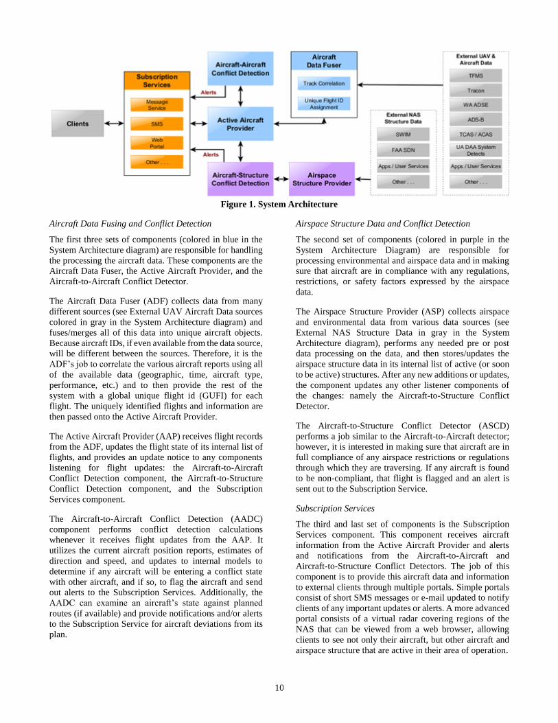
10
Figure 1. System Architecture
Aircraft Data Fusing and Conflict Detection
The first three sets of components (colored in blue in the
System Architecture diagram) are responsible for handling
the processing the aircraft data. These components are the
Aircraft Data Fuser, the Active Aircraft Provider, and the
Aircraft-to-Aircraft Conflict Detector.
The Aircraft Data Fuser (ADF) collects data from many
different sources (see External UAV Aircraft Data sources
colored in gray in the System Architecture diagram) and
fuses/merges all of this data into unique aircraft objects.
Because aircraft IDs, if even available from the data source,
will be different between the sources. Therefore, it is the
ADF’s job to correlate the various aircraft reports using all
of the available data (geographic, time, aircraft type,
performance, etc.) and to then provide the rest of the
system with a global unique flight id (GUFI) for each
flight. The uniquely identified flights and information are
then passed onto the Active Aircraft Provider.
The Active Aircraft Provider (AAP) receives flight records
from the ADF, updates the flight state of its internal list of
flights, and provides an update notice to any components
listening for flight updates: the Aircraft-to-Aircraft
Conflict Detection component, the Aircraft-to-Structure
Conflict Detection component, and the Subscription
Services component.
The Aircraft-to-Aircraft Conflict Detection (AADC)
component performs conflict detection calculations
whenever it receives flight updates from the AAP. It
utilizes the current aircraft position reports, estimates of
direction and speed, and updates to internal models to
determine if any aircraft will be entering a conflict state
with other aircraft, and if so, to flag the aircraft and send
out alerts to the Subscription Services. Additionally, the
AADC can examine an aircraft’s state against planned
routes (if available) and provide notifications and/or alerts
to the Subscription Service for aircraft deviations from its
plan.
Airspace Structure Data and Conflict Detection
The second set of components (colored in purple in the
System Architecture Diagram) are responsible for
processing environmental and airspace data and in making
sure that aircraft are in compliance with any regulations,
restrictions, or safety factors expressed by the airspace
data.
The Airspace Structure Provider (ASP) collects airspace
and environmental data from various data sources (see
External NAS Structure Data in gray in the System
Architecture diagram), performs any needed pre or post
data processing on the data, and then stores/updates the
airspace structure data in its internal list of active (or soon
to be active) structures. After any new additions or updates,
the component updates any other listener components of
the changes: namely the Aircraft-to-Structure Conflict
Detector.
The Aircraft-to-Structure Conflict Detector (ASCD)
performs a job similar to the Aircraft-to-Aircraft detector;
however, it is interested in making sure that aircraft are in
full compliance of any airspace restrictions or regulations
through which they are traversing. If any aircraft is found
to be non-compliant, that flight is flagged and an alert is
sent out to the Subscription Service.
Subscription Services
The third and last set of components is the Subscription
Services component. This component receives aircraft
information from the Active Aircraft Provider and alerts
and notifications from the Aircraft-to-Aircraft and
Aircraft-to-Structure Conflict Detectors. The job of this
component is to provide this aircraft data and information
to external clients through multiple portals. Simple portals
consist of short SMS messages or e-mail updated to notify
clients of any important updates or alerts. A more advanced
portal consists of a virtual radar covering regions of the
NAS that can be viewed from a web browser, allowing
clients to see not only their aircraft, but other aircraft and
airspace structure that are active in their area of operation.

11
UAS Integration into Terminal areas with GBSAA
The proliferation of unmanned aircraft (UAS) into the NAS
has raised safety concerns for the FAA. UAS introduction
increases the number of vehicle in the airspace. The UAS
when compared to manned aircraft are often small and hard
to ‘see,’ possess different performance characteristics,
often fly unique mission profiles, carry fewer and less
capable avionics and sensors for maintaining safe
separation, and operate out-of-sight of the UAS operator
who lacks an on the aircraft “see and avoid” capability.
Federal regulation requires pilots to be aware of all other
surrounding aircraft—either visually or using on-board
instrumentation—and to safely avoid near-misses or
collisions. Because there is no pilot physically onboard a
UAS, remote operators must resort to limiting and
sometimes impractical means of seeing and avoiding other
aircraft, such as ground-based observers or chase aircraft
behind the UAS.
The aviation community has defined a limited scope Detect
and Avoid (DAA) approach described by the RTCA SC-
228 DAA MOPS. However, the scope of the current RTCA
DAA MOPS does not include operations in terminal areas.
In today’s busier terminal areas, manned aircraft separation
is achieved by ATC use of radar systems such as the ASR-
9 / ASR-11, ADS-B, and pilot “see and avoid” behaviors.
The ASR radar systems are typically tuned to the faster and
larger manned aircraft and cannot reliably detect UAS.
To provide ATC and UAS operators see and avoid
capabilities in the terminal area, the Air Force, the MITRE
Corporation, Raytheon, the Volpe Center, members of the
FAA, and many others have been developing a Ground
Based Detect and Avoid (GBDAA) capability. The Air
Force solution processes and fuses radar data from ASR
terminal radars and from local GBSAA radars tuned to
capture slow and small targets into a display that can
provide ATC and UAS operators a detailed view of UAS
and manned aircraft operations in the terminal area.
The Air Force GBSAA solution is operational today at
Cannon Air Force Base where it fulfills the FAA’s See and
Avoid requirement (14CFR§91.113). The GBDAA system
is designed to utilize existing ground-based radar
infrastructures (ASR-9 and ASR-11) that work together
with other small target ground-based radars (STARS,
LSTAR, Sentinel) to provide operational personnel with
situational awareness of the terminal airspace. The Airport
Surveillance Radar (ASR) system allows operators to
detect positions of cooperative aircraft, while the Standard
Terminal Automation Replacement System (STARS),
LSTAR, and Sentinel systems allow operators to filter out
the airspace and detect non-cooperative aircraft. The
position and movement of aircraft is indicated on a display,
centered on the UAS, that a UAS operator can use to
facilitate self-separation. This system implements a
collision detection algorithm to alert an operator to an
impending collision with another aircraft. Audible and
visual alerts are presented to a UAS operator when a threat
aircraft enters a pre-defined area around the UAS. If
evasive action is required, additional alerts are provided to
the pilot.
The Cannon Air Force GBSAA system has obtained both
an FAA Certificate of Authorization (COA) and an
Airworthiness Military Flight Release (MFR) that allows
UAS to transit to RAs through the NAS. From this
certification case, many lessons were learned as to how to
create and gain the rigorous approval from both the FAA
and the Air Force. Since then, additional Air Force bases
have initiated the process for establishing GBSAA
systems.
As shown in Figure 2, multiple flight operations are being
performed. The GBDAA STARS screen is utilizing the
fused data from the ASR-11, as well as its own algorithm
sensors to provide a feed of all the aircraft flying in the
terminal area. Before GBDAA, UAS missions would need
to put up a Temporary Flight Restriction (TFR), in the
terminal area, so they could take off without interruptions
from other aircraft. Now, GBDAA system provides the
UAS crew with surrounding aircraft positioning
information so it can take evasive action, when necessary.
It is then an easy step to envision that the same GBDAA
produced aircraft positioning tracks being fed into a shared
distribution service. In a sense, this would provide a virtual
radar display for any UAS crew, in the operational area, to
use as a means of detect.
Figure 2. GBDAA concept to support terminal area
UAS DAA.
In the future, the fusion of a broad range of surveillance
sources will create a Virtual Radar picture for situational
awareness, enhancing both air and surface DAA, and
enabling terminal see and avoid capabilities superior to that
of manned aircraft. Figure 3 depicts a notional simplified
view of surveillance sources and the consumers of the
Virtual Radar situational awareness data. Various levels of
processing may occur at the surveillance sources, the
Virtual Radar, and by the consumers of the situational
awareness data. ATC will have direct access to the NAS
Systems and NAS Services, however the Virtual Radar
inclusion of other sources may prove valuable to ATC.

12
Aviation stakeholders include, for example, facility
managers requiring awareness of non-cooperative aircraft.
The Virtual Radar system could be managed by a federal
agency or by services created by one or more commercial
enterprises.
Figure 3. A notional view of virtual radar sources and
consumers of the situational awareness data.
5. CONCLUSIONS
This paper has reviewed the future surveillance needs in
the NAS, the diverse surveillance assets in the NAS, and
candidate system architectural alternatives for using those
surveillance assets to meet future needs. While investment
and planning will be required to meet those needs, current
and emerging surveillance technologies appear to be
sufficient to meet those needs.
ACKNOWLEDGEMENTS
The authors offer their thanks to the U.S. Department of
Transportation, the U.S. Department of Defense, and the
U.S Air Force for their support in preparing this paper.
DISCLAIMER
The text and graphics within this paper express only the
views and/or opinions of the authors as individuals and do
not represent endorsements, commitments or polices of
their firm, agency or organization.
REFERENCES
[1] FY 2018 FAA Capital Investment Plan, p. 45.
[2] Regulus-group.com, 10-14-2017.
[3] Tethered Aerostat Radar System, fas.org, (Federation
of American Scientist), 10-14-2017.
[4] “ADS-B / Airport Surface Surveillance Capability
(ASSC),” faa.gov, 10-14-2017.
[5] Surface Surveillance Industry Day Overview, FAA,
June 15, 2017.
[6] “FAA Evaluates Drone Detection Systems Around
Denver,” faa.gov, November 2016.
[7] “USAF validates Raytheon’s GBSAA radar
capabilities,” airforce-technology.com, November
2012.
[8] “Army installs first Ground-Based Sense-and-Avoid
radar,” army.mil, PEO Aviation, December 2014.
[9] Mike Thorpe, M. Kottkamp, A. Rossler, J. Schutz.,
“LTE Location Based Services Technology
Introduction White paper,” Rohde & Schwarz, April
2013.
[10] Jose Ebi, Martin Adams, John Stephen Mullane,
Nicholas M. Patrikalakis. “Predicting Millimeter
Wave Radar Spectra for Autonomous Navigation,”
IEEE Sensors Journal 10, no. 5 (May 2010): 960-971.
[11] “What is LIDAR?,” NOAA, oceanservice.noaa.gov,
august 17, 2017.
[12] Jamie Condliffe, “A Key Piece of Self-Driving Cars
Is About to Get a Lot Cheaper,” MIT Technology
Review, April 20, 2017.
BIOGRAPHY
Terry Blumer is an associate with
Aviation Management Associates
(AMA), a firm helping aviation
industry partners and government
agencies address air traffic control
challenges for over 35 years. Mr.
Blumer specializes in unmanned
systems and air traffic control
issues. Mr. Blumer led unmanned
system applications and managed
the FAA NAS Voice System
program for Harris, headed Business Development and
directed the FAA Enhanced Tower Voice Switch program
for Denro, and ran the commercial avionics product line
management organization for Bendix. Mr. Blumer earned
an MBA from the Stanford Graduate School of Business
and technical degrees from MIT’s Flight Transportation
Laboratory in the Department of Aeronautics and
Astronautics.

13
Pete Carros is a Sr. Analyst and
System Safety Engineer for Mosaic
ATM, Inc. – a firm specializing in
air traffic management systems
development, unmanned systems
and data management systems for
the aviation sector. He works
under the Autonomous Systems
Group and supports the Air Force,
through Volpe, on the Ground
Based Detect and Avoid (GBDAA)
contract. He has assisted the Air Force Safety Center’s
Remotely Piloted Aircraft (RPA) Brach, as a Systems
Safety Engineer. His prior roles include providing safety
engineering analysis on DoD Airworthiness projects,
safety oversight of Ground Base Sense and Avoid (GBSAA)
efforts, assessment and mitigation of GBDAA hazards, and
assist with investigations of RPA mishaps. He has a BSME
from the Embry Riddle Aeronautical University and is
working on a Safety Certificate from the University of
Southern California. He has completed the Chief of Safety
and Board President Course from the Air Force Safety
Center.
John DiFelici is a principle
software engineer for Mosaic
ATM, Inc. developing unmanned
software systems for the aviation
sector. He has worked for over 20
years developing air traffic
management, environmental
management, and data
management systems for the
aviation sector. He received a
B.S. in Mathematics and Physics from Santa Clara
University and his Masters of Physics from the University
of Maryland, College Park.
Jason Glaneuski is a Division
Chief in the Air Traffic
Management Systems Division at
the Volpe National
Transportation Systems Center
(Volpe Center) in Cambridge,
MA. His Division applies
information technology and
operations research disciplines
to enhance the capacity, safety,
and security of the National Airspace System. A key
component of this work is developing concepts and
designing automated decision-support tools and
capabilities that provide solutions to existing and
anticipated traffic flow issues. Mr. Glaneuski has
experience both performing and managing technical work
in the areas of traffic flow management (TFM), time-based
flow management (TBFM), and unmanned aircraft
systems (UAS) sense and avoid (SAA), among others. Mr.
Glaneuski is a graduate of Daniel Webster College
Dylan Hasson is an Operations
Research Analyst in the Air Traffic
Management Systems Division at
the Volpe National Transportation
Systems Center (Volpe Center) in
Cambridge, MA. The ATMS
division blends air traffic
operations research, information
technology, computer science, and
engineering expertise focused on
developing and deploying systems that help the air
transportation enterprise to operate safely and efficiently.
Mr. Hasson is a graduate of Rensselaer Polytechnic
Institute where he received a B.S. in Aeronautical
Engineering. He is also a private pilot.
George Hunter is a principle
analyst for Mosaic ATM, Inc. – a
firm specializing in air traffic
management systems development,
unmanned systems and data
management systems for the
aviation sector. He has 30 years of
research and development
experience in science and
engineering. For more than 20
years Dr. Hunter has conceived, performed and directed
extensive research studies. He is a graduate of the
University of Illinois where he received a Ph.D. in
Biophysics. He also received a B.S. and M.S. in Aerospace
Engineering from the University of Michigan
Robert J. Kerczewski has been
involved with research and
development of satellite and
aeronautical communications
systems and applications for the
Analex Corporation (1982-1986)
and NASA (1986-present). He
holds a BEE degree from
Cleveland State University
(1982) and an MSEE degree from
Case Western Reserve University
(1987). He is currently the Spectrum Element Manager
for the NASA’s Unmanned Aircraft Systems Integration in
the National Airspace System (UAS in the NAS)
Communications Sub Project.
Chris Wargo is a program
manager and director business
development for Mosaic ATM,
Inc. – a firm specializing in air
traffic management systems
development, unmanned systems
and data management systems for
the aviation sector. He also leads
the Autonomous Systems Group
and served as a Chair of the
System Engineering Working Group of RTCA SC-203. He
has also held positions as President of Computer Network

14
& Software, Inc., Vice President and General Manager for
ARINC, Inc., C3I Program Manager RCA Automated
Systems and GE, as well as Systems Engineer for GTE
Sylvania, Electronic Systems Group, and the US Army. In
his role as a leader in aviation next generation systems
engineering, he has participated in numerous ICAO,
RTCA, AEEC, IEEE and IATA committees and standards
working groups throughout his 30 year defense and
aeronautical systems career. He has presented a number
of papers and chaired many industry conference sessions
related to the CNS and network system programs, project
and technologies of the general, business and air transport
community. He has a BSEE from the University of
Wisconsin and an MS, Systems Engineering, from the
University of Southern California, and has attended the
Defense Systems Management College and the Advanced
Management Program at the Harvard Business School