Embed Size (px)
Citation preview
UCC28019AEVM 350-W PFC Converter
User's Guide
Literature Number: SLUU325AJune 2008–Revised May 2009
1 Description
2 Applications
3 Features
User's GuideSLUU325A–June 2008–Revised May 2009
UCC28019AEVM 350-W PFC Converter
The UCC28019A evaluation module (EVM) is a 350-W off-line Power Factor Correction (PFC) boostconverter providing a 390-V regulated output at 0.9 A of load current. The PFC converter accommodatesan input voltage range of 85 VAC to 265 VAC and uses average current mode control at a fixed frequencyof 65 kHz. The UCC28019A incorporates a wide range of protection features to ensure safe systemoperation.
The UCC28019AEVM highlights the many benefits of using the UCC28019A Continuous Current ModePFC Controller (TI Literature Number SLUS828). The controller operates under average current modecontrol at a fixed frequency of 65 kHz. Simple external current and voltage loop compensation, along withadvanced protection features, make this controller ideal for server and desktop power supplies, telecomrectifiers, and home electronics.
This user’s guide provides the schematic, component list, assembly drawing for a single-sided printedcircuit board application, and test set up necessary to evaluate the UCC28019A in a typical PFCapplication.
The UCC28019A is suited for use in high-power off-line systems requiring high-efficiency and advancedfault protection features including:• Server and desktop power supplies• Telecom rectifiers• Home electronics
The UCC28019AEVM features include:• 350-W, 390-V output• Universal off-line input voltage range• Average current mode PWM control• Fixed 65-kHz oscillator frequency• Cycle-by-cycle peak current limiting• VCC under-voltage lockout• Voltage regulation open-loop detection• Output under-voltage protection• Output over-voltage protection• AC input brown-out protection• Enhanced dynamic response• Soft-start
UCC28019AEVM 350-W PFC Converter2 SLUU325A–June 2008–Revised May 2009Submit Documentation Feedback
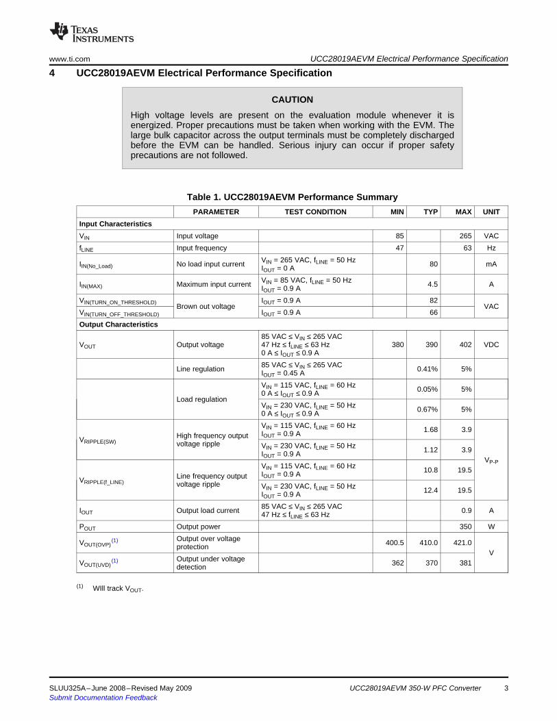
4 UCC28019AEVM Electrical Performance Specificationwww.ti.com UCC28019AEVM Electrical Performance Specification
CAUTIONHigh voltage levels are present on the evaluation module whenever it isenergized. Proper precautions must be taken when working with the EVM. Thelarge bulk capacitor across the output terminals must be completely dischargedbefore the EVM can be handled. Serious injury can occur if proper safetyprecautions are not followed.
Table 1. UCC28019AEVM Performance SummaryPARAMETER TEST CONDITION MIN TYP MAX UNIT
Input CharacteristicsVIN Input voltage 85 265 VACfLINE Input frequency 47 63 Hz
VIN = 265 VAC, fLINE = 50 HzIIN(No_Load) No load input current 80 mAIOUT = 0 AVIN = 85 VAC, fLINE = 50 HzIIN(MAX) Maximum input current 4.5 AIOUT = 0.9 A
VIN(TURN_ON_THRESHOLD) IOUT = 0.9 A 82Brown out voltage VAC
VIN(TURN_OFF_THRESHOLD) IOUT = 0.9 A 66Output Characteristics
85 VAC ≤ VIN ≤ 265 VACVOUT Output voltage 47 Hz ≤ fLINE ≤ 63 Hz 380 390 402 VDC
0 A ≤ IOUT ≤ 0.9 A85 VAC ≤ VIN ≤ 265 VACLine regulation 0.41% 5%IOUT = 0.45 AVIN = 115 VAC, fLINE = 60 Hz 0.05% 5%0 A ≤ IOUT ≤ 0.9 A
Load regulationVIN = 230 VAC, fLINE = 50 Hz 0.67% 5%0 A ≤ IOUT ≤ 0.9 AVIN = 115 VAC, fLINE = 60 Hz 1.68 3.9IOUT = 0.9 AHigh frequency outputVRIPPLE(SW) voltage ripple VIN = 230 VAC, fLINE = 50 Hz 1.12 3.9IOUT = 0.9 A
VP-PVIN = 115 VAC, fLINE = 60 Hz 10.8 19.5IOUT = 0.9 ALine frequency outputVRIPPLE(f_LINE) voltage ripple VIN = 230 VAC, fLINE = 50 Hz 12.4 19.5IOUT = 0.9 A85 VAC ≤ VIN ≤ 265 VACIOUT Output load current 0.9 A47 Hz ≤ fLINE ≤ 63 Hz
POUT Output power 350 WOutput over voltageVOUT(OVP)
(1) 400.5 410.0 421.0protectionV
Output under voltageVOUT(UVD)(1) 362 370 381detection
(1) WIll track VOUT.
SLUU325A–June 2008–Revised May 2009 UCC28019AEVM 350-W PFC Converter 3Submit Documentation Feedback
UCC28019AEVM Electrical Performance Specification www.ti.com
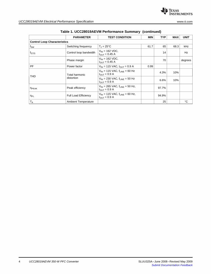
Table 1. UCC28019AEVM Performance Summary (continued)PARAMETER TEST CONDITION MIN TYP MAX UNIT
Control Loop CharacteristicsfSW Switching frequency TJ = 25°C 61.7 65 68.3 kHz
VIN = 162 VDC,f(CO) Control loop bandwidth 14 HzIOUT = 0.45 AVIN = 162 VDC,Phase margin 70 degreesIOUT = 0.45 A
PF Power factor VIN = 115 VAC, IOUT = 0.9 A 0.99VIN = 115 VAC, fLINE = 60 Hz 4.3% 10%IOUT = 0.9 ATotal harmonicTHD distortion VIN = 230 VAC, fLINE = 50 Hz 6.6% 10%IOUT = 0.9 AVIN = 265 VAC, fLINE = 50 Hz,ηPEAK Peak efficiency 97.7%IOUT = 0.9 AVIN = 115 VAC, fLINE = 60 Hz,ηFL Full Load Efficiency 94.9%IOUT = 0.9 A
TA Ambient Temperature 25 °C
4 UCC28019AEVM 350-W PFC Converter SLUU325A–June 2008–Revised May 2009Submit Documentation Feedback
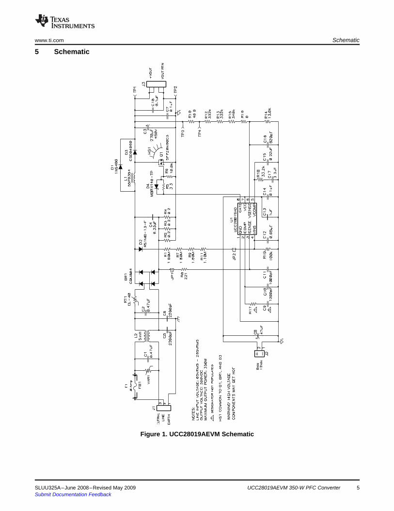
5 Schematic
+
+
www.ti.com Schematic
Figure 1. UCC28019AEVM Schematic
SLUU325A–June 2008–Revised May 2009 UCC28019AEVM 350-W PFC Converter 5Submit Documentation Feedback
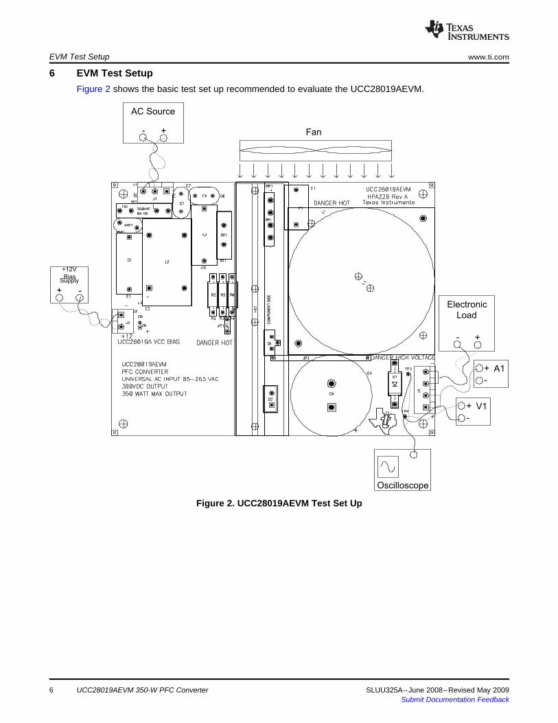
6 EVM Test Setup
+12V
BiasSupply
+ -
AC Source
+-
Electronic
Load
+-
Fan
V1
-
+
A1
-
+
Oscilloscope
EVM Test Setup www.ti.com
Figure 2 shows the basic test set up recommended to evaluate the UCC28019AEVM.
Figure 2. UCC28019AEVM Test Set Up
UCC28019AEVM 350-W PFC Converter6 SLUU325A–June 2008–Revised May 2009Submit Documentation Feedback
6.1 AC Source
6.2 12-V Bias Supply
6.3 Electronic Load
6.4 Digital Multimeters
6.5 Recommended Wire Gauge
6.6 Fan
www.ti.com EVM Test Setup
The ac input source shall be capable of supplying between 85 VAC and 265 VAC at no less than 8 Apeak. Connect the ac source to the L and N terminals of J1 on the EVM as shown in Figure 2.
The bias supply to the device shall be capable of supplying up to 12 VDC at no less than 10 mA. Connectthe bias supply to the – and +12 terminals of J2, UCC28019A VCC BIAS, as shown in Figure 2.
A programmable electronic load set to constant current mode and capable of sinking 0 A to 1 A at 390VDC shall be used.
For highest accuracy, the output voltage of the UCC28019AEVM shall be monitored by connecting adigital voltmeter, V1, directly across TP1 and TP2 with the positive terminal at TP1 and the negativeterminal at TP2, as shown in Figure 2. A dc current meter, A1, should be placed in series with theelectronic load for accurate output current measurements.
The connection between the ac source and the EVM input terminals can carry as much as 8 A peakduring brownout testing. The recommended wire size is AWG #16 with the total length of wire less than 8feet (4 feet input, 4 feet return). The connection between the EVM output terminals (J3) and the electronicload can carry as much as 1 A. The minimum recommended wire size is AWG #20, with the total length ofwire less than 8 feet (4 feet output, 4 feet return).
A fan, capable of 200 LFM to 400 LFM, should be used to maintain component temperatures within safeoperating ranges at all times during operation of the UCC28019AEVM. Position the fan so as to blowalong the length of the heatsink as shown in Figure 2.
SLUU325A–June 2008–Revised May 2009 UCC28019AEVM 350-W PFC Converter 7Submit Documentation Feedback
7 Power-Up/Power-Down ProcedurePower-Up/Power-Down Procedure www.ti.com
The following test procedure is recommended primarily for power up and shutting down the evaluationmodule. Never leave a powered EVM unattended for any length of time. Also, the unit should never behandled while power is applied to it or the output voltage is greater than 50 VDC.
WARNINGThere are very high voltages present on the EVM. Somecomponents will reach temperatures above 50°C. Precautions mustbe taken when handling the board. Never operate theUCC28019AEVM without the fan running. Always make certain thebulk capacitors have completely discharged prior to handling theEVM.
1. Working at an ESD workstation, make sure that the ionizer is on before the EVM is removed from theprotective packaging and power is applied. Electrostatic smock and safety glasses should also beworn. Because voltages in excess of 400 V may be present on the EVM, do not connect the groundstrap from the smock to the bench.
2. Power-UPa. Connect the equipment as shown in Figure 2.b. Turn on the fan.c. Prior to turning on the ac source, limit the source current to 8 A and then turn on the ac source.d. Turn on the 12-V bias supply and verify that the output is within regulation.e. Increase the load from 0 A up to 0.9 A.f. The DRAIN, SOURCE, GATE, SWITCH node, RETURN, and VOUT+ are labeled on the surface
mount side of the board for user access.3. Power-Down
a. Turn off ac source.b. Turn off bias supply.c. Discharge the output capacitor.d. Turn off the load.
UCC28019AEVM 350-W PFC Converter8 SLUU325A–June 2008–Revised May 2009Submit Documentation Feedback
8 UCC28019AEVM Performance Data and Characteristic Curves
0 0.1 0.2 0.3 0.6 0.7 0.9
Load Current - A
0.8
0.84
0.88
0.92
0.96
1.0
0.4 0.5 0.8
0.82
0.86
0.90
0.94
0.98
h-
Effic
ien
cy
-%
115 VAC,
60 Hz
85 VAC, 50
Hz
230 VAC,
50 Hz
265 VAC,
50 Hz
EFFICIENCY
vs
LOAD CURRENT
0 0.2 0.6 0.9
Load Current - A
0.50
0.60
0.70
0.80
0.95
1.05
0.4 0.8
0.55
0.65
0.75
0.85
1.00
Po
we
rF
ac
to
r
POWER FACTOR
vs
LOAD CURRENT
115 VAC,
60 Hz
85 VAC,
50 Hz
230 VAC,
50 Hz
265 VAC,
50 Hz
0.90
0 0.2 0.6 0.9
Load Current - A
0
5
10
20
25
0.4 0.8
15
TH
D-
To
ta
lH
arm
on
icD
isto
rtio
n-
%
TOTAL HARMONIC DISTORTION
vs
LOAD CURRENT
115 VAC,
60 Hz
85 VAC,
50 Hz
230 VAC,
50 Hz
265 VAC,
50 Hz
0 0.2 0.6 0.9
Load Current - A
380
385
395
0.4 0.8
390
VO
UT
-O
utp
ut
Vo
lta
ge
-V
OUTPUT VOLTAGE
vs
LOAD CURRENT
115 VAC,
60 Hz
85 VAC,
50 Hz
230 VAC,
50 Hz
265 VAC,
50 Hz
0.1 0.3 0.5 0.7
www.ti.com UCC28019AEVM Performance Data and Characteristic Curves
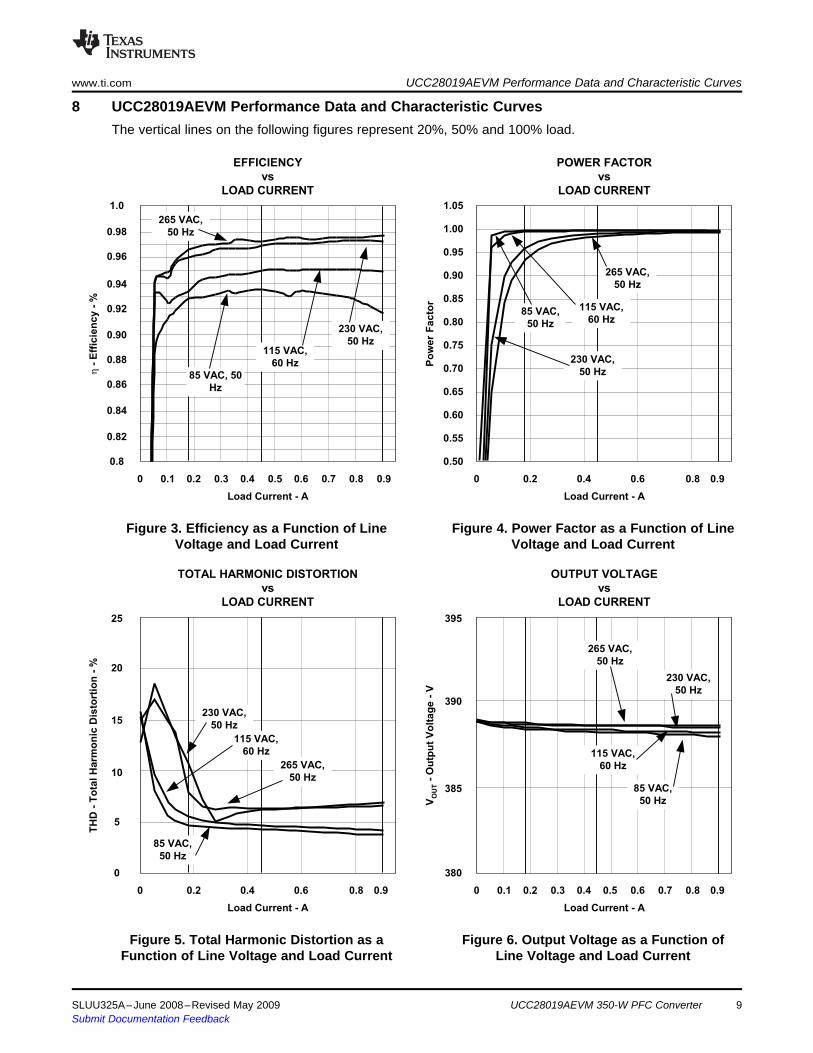
The vertical lines on the following figures represent 20%, 50% and 100% load.
Figure 3. Efficiency as a Function of Line Figure 4. Power Factor as a Function of LineVoltage and Load Current Voltage and Load Current
Figure 5. Total Harmonic Distortion as a Figure 6. Output Voltage as a Function ofFunction of Line Voltage and Load Current Line Voltage and Load Current
SLUU325A–June 2008–Revised May 2009 UCC28019AEVM 350-W PFC Converter 9Submit Documentation Feedback
3
Harmonic Number
0.00
0.04
Am
pli
tu
de
-A
CURRENT HARMONICS
(230 VDC, 50 Hz full load)
0.01
0.03
0.02
0.05
0.06
7 11 15 19 23 27 31 35 39
HPA226
EN61000-3-2 Class D max
0.07
0.11
0.08
0.10
0.09
0.12
0.13
0.14
0.15
1
Harmonic Number
0.00
0.40
Am
pli
tu
de
-A
CURRENT HARMONICS
0.10
0.30
0.20
0.50
0.60
5 9 13 17 21 25 29 33 37
0.70
1.10
0.80
1.00
0.90
1.20
1.30
1.40
1.50
1.60
1.70
0.000
Time - s
-180
-60
180
60
VIN
-In
pu
tV
olt
ag
e-
V-
dB
INPUT VOLTAGE/CURRENT
vs
TIME
0.020
I IN-
Inp
ut
Cu
rre
nt
-A
-150
-90
-120
-30
0
30
90
120
150
-6
-2
6
2
-5
-3
-4
-1
0
1
3
4
5
Input
Current
Input
Voltage
0.010 0.015 0.025 0.0300.005
UCC28019AEVM Performance Data and Characteristic Curves www.ti.com
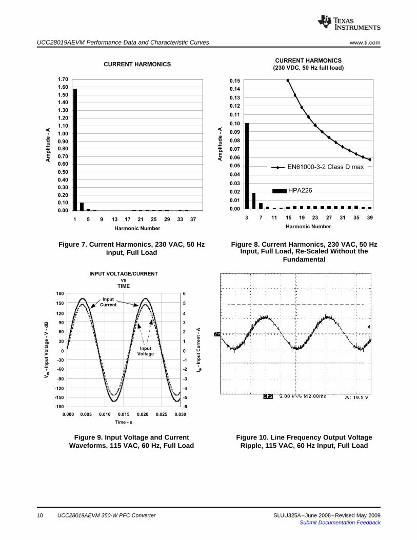
Figure 7. Current Harmonics, 230 VAC, 50 Hz Figure 8. Current Harmonics, 230 VAC, 50 HzInput, Full Load, Re-Scaled Without theinput, Full Load
Fundamental
Figure 9. Input Voltage and Current Figure 10. Line Frequency Output VoltageWaveforms, 115 VAC, 60 Hz, Full Load Ripple, 115 VAC, 60 Hz Input, Full Load
10 UCC28019AEVM 350-W PFC Converter SLUU325A–June 2008–Revised May 2009Submit Documentation Feedback
www.ti.com UCC28019AEVM Performance Data and Characteristic Curves
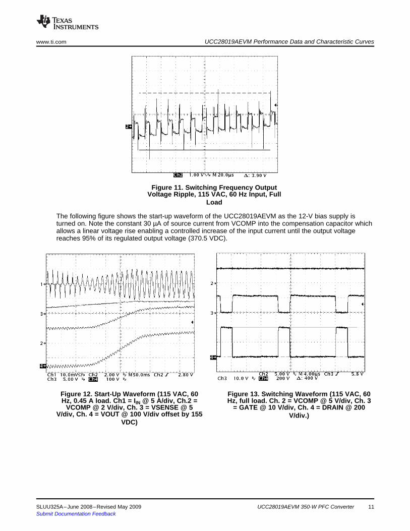
Figure 11. Switching Frequency OutputVoltage Ripple, 115 VAC, 60 Hz Input, Full
Load
The following figure shows the start-up waveform of the UCC28019AEVM as the 12-V bias supply isturned on. Note the constant 30 µA of source current from VCOMP into the compensation capacitor whichallows a linear voltage rise enabling a controlled increase of the input current until the output voltagereaches 95% of its regulated output voltage (370.5 VDC).
Figure 12. Start-Up Waveform (115 VAC, 60 Figure 13. Switching Waveform (115 VAC, 60Hz, 0.45 A load. Ch1 = IIN @ 5 A/div, Ch.2 = Hz, full load. Ch. 2 = VCOMP @ 5 V/div, Ch. 3
VCOMP @ 2 V/div, Ch. 3 = VSENSE @ 5 = GATE @ 10 V/div, Ch. 4 = DRAIN @ 200V/div, Ch. 4 = VOUT @ 100 V/div offset by 155 V/div.)
VDC)
SLUU325A–June 2008–Revised May 2009 UCC28019AEVM 350-W PFC Converter 11Submit Documentation Feedback
1 100
Frequency - Hz
-120
-40
120
40
Gain
-d
B
GAIN/PHASE
vs
FREQUENCY (162 VDC, 0.9 A load)
10
Ph
ase
-d
eg
rees
-100
-60
-80
-20
0
20
60
80
100
-120
-40
120
40
-100
-60
-80
-20
0
20
60
80
100Phase
Gain
UCC28019AEVM Performance Data and Characteristic Curves www.ti.com
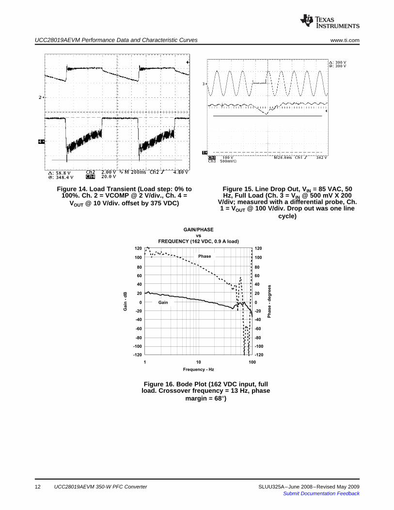
Figure 14. Load Transient (Load step: 0% to Figure 15. Line Drop Out, VIN = 85 VAC, 50100%. Ch. 2 = VCOMP @ 2 V/div., Ch. 4 = Hz, Full Load (Ch. 3 = VIN @ 500 mV X 200
V/div; measured with a differential probe, Ch.VOUT @ 10 V/div. offset by 375 VDC)1 = VOUT @ 100 V/div. Drop out was one line
cycle)
Figure 16. Bode Plot (162 VDC input, fullload. Crossover frequency = 13 Hz, phase
margin = 68°)
UCC28019AEVM 350-W PFC Converter12 SLUU325A–June 2008–Revised May 2009Submit Documentation Feedback
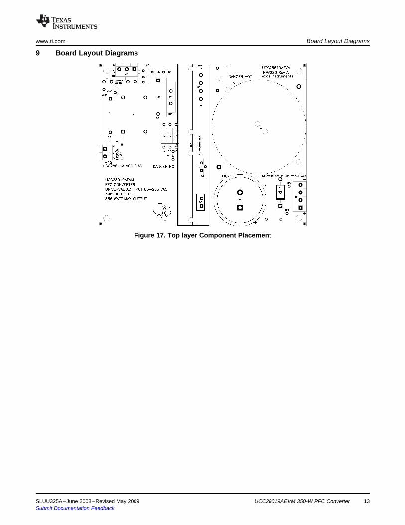
9 Board Layout Diagramswww.ti.com Board Layout Diagrams
Figure 17. Top layer Component Placement
SLUU325A–June 2008–Revised May 2009 UCC28019AEVM 350-W PFC Converter 13Submit Documentation Feedback
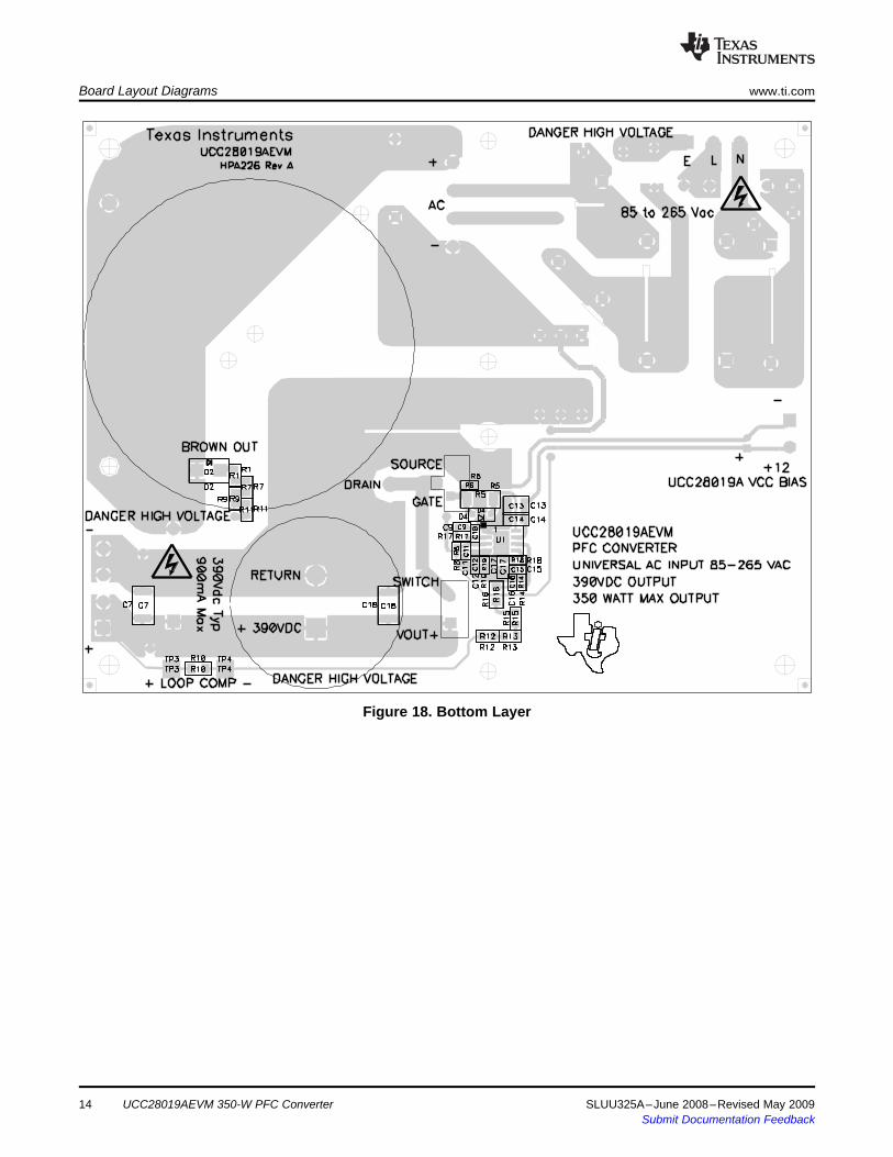
Board Layout Diagrams www.ti.com
Figure 18. Bottom Layer
UCC28019AEVM 350-W PFC Converter14 SLUU325A–June 2008–Revised May 2009Submit Documentation Feedback
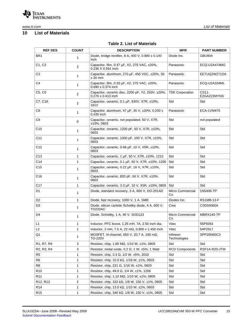
10 List of Materialswww.ti.com List of Materials
Table 2. List of MaterialsREF DES COUNT DESCRIPTION MFR PART NUMBER
BR1 Diode, bridge rectifier, 8 A, 400 V, 0.880 x 0.140 Diode Inc. GBU8041 inchC1, C2 Capacitor, film, 0.47 µF, X2, 275 VAC, ±20%, Panasonic ECQ-U2A474MG2 0.236 X 0.591 inchC3 Capacitor, aluminum, 270 µF, 450 VDC, ±20%, 30 Panasonic EETUQ2W271DA1 x 30 mmC4 Capacitor, film, 0.33 µF, X2, 275 VAC, ±20%, Panasonic ECQ-U2A334ML1 0.690 x 0.374 inchC5, C6 Capacitor, ceramic disc, 2200 pF, Y2, 250V, ±20%, TDK Corporation CS11-2 0.276 x 0.413 inch E2GA222MYNSC7, C18 Capacitor, ceramic, 0.1 µF, 630V, X7R, ±10%, Std Std2 1812C8 Capacitor, aluminum, 47 µF, 35 V, ±20%, 0.200 x Panasonic ECA-1VM4701 0.435 inchC9 Capacitor, ceramic, not populated, 50 V, X7R, Std not populated0 ±10%, 0603C10 Capacitor, ceramic, 1200 pF, 50 V, X7R, ±10%, Std Std1 0603C11 Capacitor, ceramic, 1000 pF, 100 V, X7R, ±10%, Std Std1 0603C12 Capacitor, ceramic, 0.68 µF, 10 V, X5R, ±10%, Std Std1 0603C13 1 Capacitor, ceramic, 1 µF, 50 V, X7R, ±10%, 1210 Std StdC14 1 Capacitor, ceramic, 0.1 µF, 50 V, X7R, ±10%, 1206 Std StdC15 Capacitor, ceramic, 0.22 µF, 16 V, X7R, ±10%, Std Std1 0603C16 Capacitor, ceramic, 820 pF, 50 V, X7R, ±10%, Std Std1 0603C17 1 Capacitor, ceramic, 3.3 µF, 10 V, X5R, ±10%, 0805 Std StdD1 Diode, standard recovery, 3 A, 600 V, DO-201AD Micro Commercial 1N5406-TP1 Co.D2 1 Diode, fast recovery, 1000 V, 1 A, SMB Diodes Inc. RS1MB-13-FD3 Diode, silicon carbide Schottky diode, 4 A, 600 V, Cree CSD04060A1 TO220ACD4 Diode, Schottky, 1 A, 40 V, SOD123 Micro Commercial MBRX140-TP1 Co.L1 1 Inductor, PFC boost, 1.25 mH, 7A, 2.50 inch dia. Vitec 55P9354L2 1 Inductor, 2 mH, 7.5 A, 22 mΩ, 0.800 x 1.450 inch Vitec 54P2917Q1 MOSFET, N-channel, 650 V, 20.7 A, 190 mΩ, Infineon SPP20N60C31 TO-220V TechnologiesR1, R7, R9 3 Resistor, chip, 1.80 MΩ, 1/10 W, ±1%, 0805 Std StdR2, R3, R4 3 Resistor, metal oxide, 0.2 Ω, 1 W, ±5%, 1 Watt RCD Components RSF1A-R20-JTWR5 1 Resistor, chip, 3.3 Ω, 1/2 W, ±5%, 2010 Std StdR6 1 Resistor, chip, 10.0 kΩ, 1/16 W, ±1%, 0603 Std StdR8 1 Resistor, chip, 221 Ω, 1/16 W, ±1%, 0603 Std StdR10 1 Resistor, chip, 49.9 Ω, 1/4 W, ±1%, 1206 Std StdR11 1 Resistor, chip, 1.10 MΩ, 1/10 W, ±1%, 0805 Std StdR12, R13 2 Resistor, chip, 332 kΩ, 1/8 W, 150 V, ±1%, 0805 Std StdR14 1 Resistor, chip, 13.0 kΩ, 1/10 W, ±1%, 0603 Std StdR15 1 Resistor, chip, 340 kΩ, 1/8 W, 150 V, ±1%, 0805 Std Std
SLUU325A–June 2008–Revised May 2009 UCC28019AEVM 350-W PFC Converter 15Submit Documentation Feedback
11 7. References
7. References www.ti.com
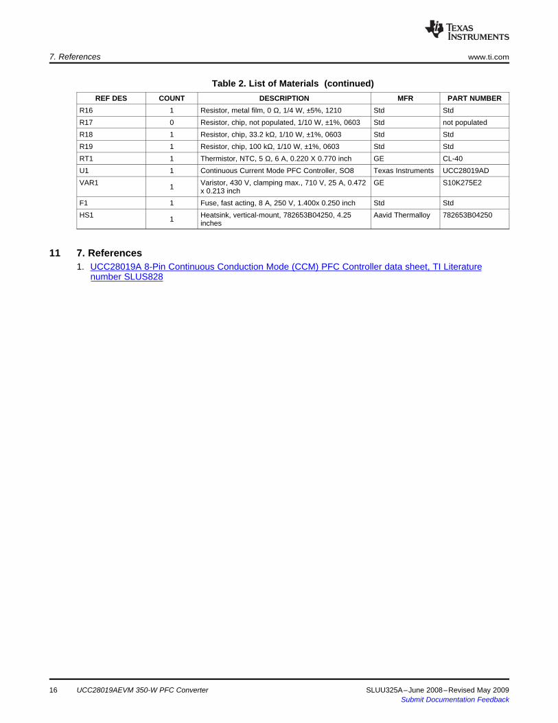
Table 2. List of Materials (continued)REF DES COUNT DESCRIPTION MFR PART NUMBER
R16 1 Resistor, metal film, 0 Ω, 1/4 W, ±5%, 1210 Std StdR17 0 Resistor, chip, not populated, 1/10 W, ±1%, 0603 Std not populatedR18 1 Resistor, chip, 33.2 kΩ, 1/10 W, ±1%, 0603 Std StdR19 1 Resistor, chip, 100 kΩ, 1/10 W, ±1%, 0603 Std StdRT1 1 Thermistor, NTC, 5 Ω, 6 A, 0.220 X 0.770 inch GE CL-40U1 1 Continuous Current Mode PFC Controller, SO8 Texas Instruments UCC28019ADVAR1 Varistor, 430 V, clamping max., 710 V, 25 A, 0.472 GE S10K275E21 x 0.213 inchF1 1 Fuse, fast acting, 8 A, 250 V, 1.400x 0.250 inch Std StdHS1 Heatsink, vertical-mount, 782653B04250, 4.25 Aavid Thermalloy 782653B042501 inches
1. UCC28019A 8-Pin Continuous Conduction Mode (CCM) PFC Controller data sheet, TI Literaturenumber SLUS828
16 UCC28019AEVM 350-W PFC Converter SLUU325A–June 2008–Revised May 2009Submit Documentation Feedback

IMPORTANT NOTICETexas Instruments Incorporated and its subsidiaries (TI) reserve the right to make corrections, modifications, enhancements, improvements,and other changes to its products and services at any time and to discontinue any product or service without notice. Customers shouldobtain the latest relevant information before placing orders and should verify that such information is current and complete. All products aresold subject to TI’s terms and conditions of sale supplied at the time of order acknowledgment.TI warrants performance of its hardware products to the specifications applicable at the time of sale in accordance with TI’s standardwarranty. Testing and other quality control techniques are used to the extent TI deems necessary to support this warranty. Except wheremandated by government requirements, testing of all parameters of each product is not necessarily performed.TI assumes no liability for applications assistance or customer product design. Customers are responsible for their products andapplications using TI components. To minimize the risks associated with customer products and applications, customers should provideadequate design and operating safeguards.TI does not warrant or represent that any license, either express or implied, is granted under any TI patent right, copyright, mask work right,or other TI intellectual property right relating to any combination, machine, or process in which TI products or services are used. Informationpublished by TI regarding third-party products or services does not constitute a license from TI to use such products or services or awarranty or endorsement thereof. Use of such information may require a license from a third party under the patents or other intellectualproperty of the third party, or a license from TI under the patents or other intellectual property of TI.Reproduction of TI information in TI data books or data sheets is permissible only if reproduction is without alteration and is accompaniedby all associated warranties, conditions, limitations, and notices. Reproduction of this information with alteration is an unfair and deceptivebusiness practice. TI is not responsible or liable for such altered documentation. Information of third parties may be subject to additionalrestrictions.Resale of TI products or services with statements different from or beyond the parameters stated by TI for that product or service voids allexpress and any implied warranties for the associated TI product or service and is an unfair and deceptive business practice. TI is notresponsible or liable for any such statements.TI products are not authorized for use in safety-critical applications (such as life support) where a failure of the TI product would reasonablybe expected to cause severe personal injury or death, unless officers of the parties have executed an agreement specifically governingsuch use. Buyers represent that they have all necessary expertise in the safety and regulatory ramifications of their applications, andacknowledge and agree that they are solely responsible for all legal, regulatory and safety-related requirements concerning their productsand any use of TI products in such safety-critical applications, notwithstanding any applications-related information or support that may beprovided by TI. Further, Buyers must fully indemnify TI and its representatives against any damages arising out of the use of TI products insuch safety-critical applications.TI products are neither designed nor intended for use in military/aerospace applications or environments unless the TI products arespecifically designated by TI as military-grade or "enhanced plastic." Only products designated by TI as military-grade meet militaryspecifications. Buyers acknowledge and agree that any such use of TI products which TI has not designated as military-grade is solely atthe Buyer's risk, and that they are solely responsible for compliance with all legal and regulatory requirements in connection with such use.TI products are neither designed nor intended for use in automotive applications or environments unless the specific TI products aredesignated by TI as compliant with ISO/TS 16949 requirements. Buyers acknowledge and agree that, if they use any non-designatedproducts in automotive applications, TI will not be responsible for any failure to meet such requirements.Following are URLs where you can obtain information on other Texas Instruments products and application solutions:Products ApplicationsAmplifiers amplifier.ti.com Audio www.ti.com/audioData Converters dataconverter.ti.com Automotive www.ti.com/automotiveDLP® Products www.dlp.com Broadband www.ti.com/broadbandDSP dsp.ti.com Digital Control www.ti.com/digitalcontrolClocks and Timers www.ti.com/clocks Medical www.ti.com/medicalInterface interface.ti.com Military www.ti.com/militaryLogic logic.ti.com Optical Networking www.ti.com/opticalnetworkPower Mgmt power.ti.com Security www.ti.com/securityMicrocontrollers microcontroller.ti.com Telephony www.ti.com/telephonyRFID www.ti-rfid.com Video & Imaging www.ti.com/videoRF/IF and ZigBee® Solutions www.ti.com/lprf Wireless www.ti.com/wireless
Mailing Address: Texas Instruments, Post Office Box 655303, Dallas, Texas 75265Copyright © 2009, Texas Instruments Incorporated


![Bridgeless Buck-Boost PFC Converter for Multistring LED Driver€¦ · boost converter as a universal PFC converter [6]. In order to address these issues, a buck-boost converter is](https://img.pdfslide.net/doc/110x75/5eaabf2a4ab79d1e774f9005/bridgeless-buck-boost-pfc-converter-for-multistring-led-driver-boost-converter-as.jpg)