Embed Size (px)
Citation preview
Kommunikationssysteme
Teil 2: Protokolle und Anwendungen
Übungen
Edition 0.2, April 2014Autor: Stephan Rupp
Informatik MasterstudiumComputing & Communications, PM2100.1
S. Rupp, 2014 Übungen_Kommunikationssysteme_PM_2001_1_Teil_2 1/74
Inhaltsverzeichnis1. Eine Nachricht schicken! 4
2. Rahmenprotokoll! 4
3. Netztopologie! 6
4. Verfügbarkeit! 7
5. Distributed Computing! 8
6. Service Inventory ! 9
7. Names, Adresses und Identities! 10
8. Name Spaces (Namensräume)! 11
9. Clients and Servers! 12
10. Threads and Processes! 13
11. Memory Leak! 13
12. Viruses and Trojan Horses! 13
13. Service Discovery! 13
14. Bluetooth! 13
15. File-Sharing! 13
16. IPSec! 14
17. IP-VPN! 14
18. Collisions in Piconets! 15
19. Protocol Overhead in VoIP! 16
20. Shopping carts! 17
21. Output Buffer! 17
22. Relations at Examination Time! 17
23. Evaluation of Results! 18
24. Service Discovery! 21
25. UPNP Remote Control! 24
Informatik MasterstudiumComputing & Communications, PM2100.1
S. Rupp, 2014 Übungen_Kommunikationssysteme_PM_2001_1_Teil_2 2/74
26. Client-Server Communication! 26
27. Home Networks! 28
28. Mobile Peer-to-Peer Networks! 30
29. CORBA and RMI! 32
30. CORBA and Web-Services! 33
31. Remote Control for Home Networks! 33
32. Remote Player! 35
33. Universal Remote Control! 37
34. Ethernet basierte Feldbusse! 39
35. Anlagensteuerung! 40
36. Regler mit Anzeige! 48
37. Topologie-Erkennungsdienst! 50
38. Vorfahrt für Prozessdaten! 53
39. Speicherprogrammierbare Steuerung (SPS)! 54
40. Feldbus! 55
41. Ablaufwarteschlange! 59
42. Verfahrene Situationen! 60
43. Task-Synchronisation! 61
44. Vernetzter Feldbus! 62
45. CAN Open als Feldbus! 63
Informatik MasterstudiumComputing & Communications, PM2100.1
S. Rupp, 2014 Übungen_Kommunikationssysteme_PM_2001_1_Teil_2 3/74
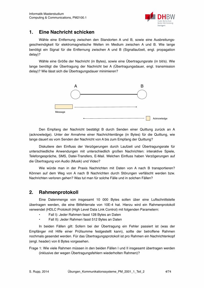
1. Eine Nachricht schickenWähle eine Entfernung zwischen den Standorten A und B, sowie eine Ausbreitungs-
geschwindigkeit für elektromagnetische Wellen im Medium zwischen A und B. Wie lange benötigt ein Signal für die Entfernung zwischen A und B (Signallaufzeit, engl. propagation delay)?
Wähle eine Größe der Nachricht (in Bytes), sowie eine Übertragungsrate (in bit/s). Wie lange benötigt die Übertragung der Nachricht bei A (Übertragungsdauer, engl. transmission delay)? Wie lässt sich die Übertragungsdauer minimieren?
!
A B
Message
Acknowledge
Sonntag, 5. Februar 12
Den Empfang der Nachricht bestätigt B durch Senden einer Quittung zurück an A (acknowledge). Unter der Annahme einer Nachrichtenlänge (in Bytes) für die Quittung, wie lange dauert es vom Senden der Nachricht von A bis zum Empfang der Quittung?
Diskutiere den Einfluss der Verzögerungen durch Laufzeit und Übertragungsrate für unterschiedliche Anwendungen mit unterschiedlich großen Nachrichten: interaktive Spiele, Telefongespräche, SMS, Datei-Transfers, E-Mail. Welchen Einfluss haben Verzögerungen auf die Übertragung von Audio (Musik) und Video?
Wie würde man in der Praxis Nachrichten mit Daten von A nach B transportieren? Können auf dem Weg von A nach B Nachrichten durch Störungen verfälscht werden bzw. Nachrichten verloren gehen? Was tut man für solche Fälle und in solchen Fällen?
2. RahmenprotokollEine Datenmenge von insgesamt 10 000 Bytes sollen über eine Luftschnittstelle
übertragen werden, die eine Bitfehlerrate von 10E-4 hat. Hierzu wird ein Rahmenprotokoll verwendet (HDLC Protokoll (High Level Data Link Control) mit folgenden Parametern:
• Fall I): Jeder Rahmen fasst 128 Bytes an Daten• Fall II): Jeder Rahmen fasst 512 Bytes an Daten
In beiden Fällen gilt: Sofern bei der Übertragung ein Fehler passiert ist (was der Empfänger mit Hilfe einer Prüfsumme festgestellt kann), sollte der betroffene Rahmen nochmals gesendet werden. Für das Übertragungsprotokoll ist pro Rahmen ein Nachrichtenkopf (engl. header) von 6 Bytes vorgesehen.
Frage 1: Wie viele Rahmen müssen in den beiden Fällen I und II insgesamt übertragen werden (inklusive der wegen Übertragungsfehlern wiederholten Rahmen)?
Informatik MasterstudiumComputing & Communications, PM2100.1
S. Rupp, 2014 Übungen_Kommunikationssysteme_PM_2001_1_Teil_2 4/74
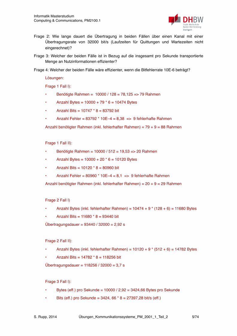
Frage 2: Wie lange dauert die Übertragung in beiden Fällen über einen Kanal mit einer Übertragungsrate von 32000 bit/s (Laufzeiten für Quittungen und Wartezeiten nicht eingerechnet)?
Frage 3: Welcher der beiden Fälle ist in Bezug auf die insgesamt pro Sekunde transportierte Menge an Nutzinformationen effizienter?
Frage 4: Welcher der beiden Fälle wäre effizienter, wenn die Bitfehlerrate 10E-6 beträgt?
Lösungen:
Frage 1 Fall I):
• Benötigte Rahmen = 10000 / 128 = 78,125 => 79 Rahmen
• Anzahl Bytes = 10000 + 79 * 6 = 10474 Bytes
• Anzahl Bits = 10747 * 8 = 83792 bit
• Anzahl Fehler = 83792 * 10E–4 = 8,38 => 9 fehlerhafte Rahmen
Anzahl benötigter Rahmen (inkl. fehlerhafter Rahmen) = 79 + 9 = 88 Rahmen
Frage 1 Fall II):
• Benötigte Rahmen = 10000 / 512 = 19,53 => 20 Rahmen
• Anzahl Bytes = 10000 + 20 * 6 = 10120 Bytes
• Anzahl Bits = 10120 * 8 = 80960 bit
• Anzahl Fehler = 80960 * 10E–4 = 8,1 => 9 fehlerhafte Rahmen!
Anzahl benötigter Rahmen (inkl. fehlerhafter Rahmen) = 20 + 9 = 29 Rahmen
Frage 2 Fall I)
• Anzahl Bytes (inkl. fehlerhafter Rahmen) = 10474 + 9 * (128 + 6) = 11680 Bytes
• Anzahl Bits = 11680 * 8 = 93440 bit
Übertragungsdauer = 93440 / 32000 = 2,92 s
Frage 2 Fall II):
• Anzahl Bytes (inkl. fehlerhafter Rahmen) = 10120 + 9 * (512 + 6) = 14782 Bytes
• Anzahl Bits = 14782 * 8 = 118256 bit
Übertragungsdauer = 118256 / 32000 = 3,7 s
Frage 3 Fall I):
• Bytes (eff.) pro Sekunde = 10000 / 2,92 = 3424,66 Bytes pro Sekunde
• Bits (eff.) pro Sekunde = 3424, 66 * 8 = 27397,28 bit/s (eff.)
Informatik MasterstudiumComputing & Communications, PM2100.1
S. Rupp, 2014 Übungen_Kommunikationssysteme_PM_2001_1_Teil_2 5/74

Frage 3 Fall II):
• Bytes (eff.) pro Sekunde = 10000 / 3,7 = 2702,70 Bytes pro Sekunde
• Bits (eff.) pro Sekunde = 2702, 70 * 8 = 21621,6 bit/s (eff.)
Antwort auf Frage 3: Fall I ist effizienter.
Frage 4) Bei einer Bitfehlerrate von 10-6 erhält man in beiden Fällen einen fehlerhaften Rahmen (siehe Antworten zu Frage 1).
Frage 4) Fall I:
• Anzahl der Bytes (inkl. fehlerhafte Rahmen) = 10474 + 1 * (128 + 6) = 10608 Bytes
• Anzahl der Bits = 10608 * 8 = 84864 bit
Übertragungsdauer = 84864 / 3200 = 2,65 s
Frage 4 Fall II:
• Anzahl der Bytes (inkl. fehlerhafte Rahmen) = 10120 + 1 * (512 + 6) = 10638 Bytes
• Anzahl der Bits = 10638 * 8 = 85104 bit
Übertragungsdauer = 85101 / 3200 = 2,66 s
Antwort auf Frage 4): Beide Rahmengrößen sind vergleichbar effizient.
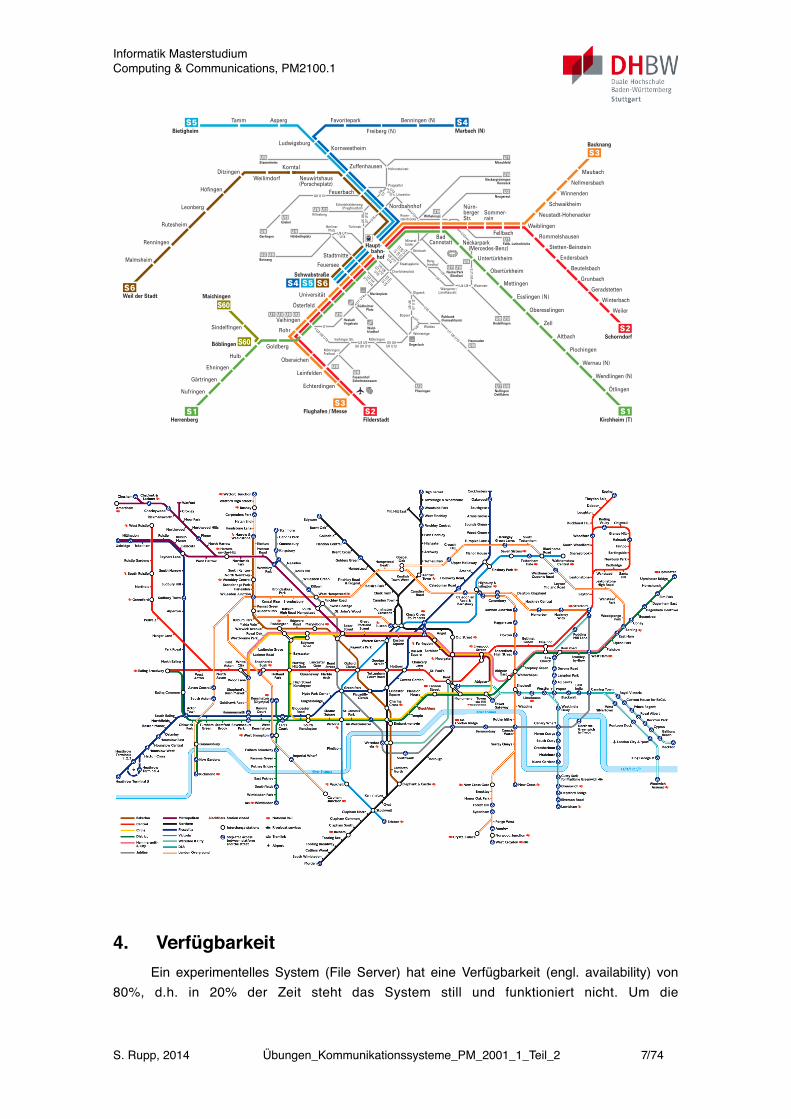
3. NetztopologieBeschreibe die in der folgenden beiden Abbildung gezeigten Netzwerke. Worin bestehen
die Unterschiede? Was könnte man unter dem Begriff „Topologie“ verstehen?
Nachrichten über das Netz schicken: Wähle zwei Endpunkte A und B für den Versand einer Nachricht. Auf welchem Weg gelangt die Nachricht von A nach B? Wie kann das Netz die Nachricht eigenständig von A nach B befördern?
Wie wird eine Route ausgewählt? Wie geht man vor, wenn mehrere Wege von A nach B führen?
Informatik MasterstudiumComputing & Communications, PM2100.1
S. Rupp, 2014 Übungen_Kommunikationssysteme_PM_2001_1_Teil_2 6/74
Wald-friedhof
Marienplatz
Möhringen
MöhringenFreibad
Vaihinger Str.Degerloch
Waldau
Charlottenplatz
Staatsgalerie
BerlinerPlatz
Stöckach
Berg-friedhof
Mineral-bäder
Ruhbank(Fernsehturm)
Wasenstr.Wangener-/
Landhausstr.
NeckarPark(Stadion)
Pragsattel
Hohensteinstr.
Löwentor
Gerlingen
Giebel
Killesberg
Türlenstr.
Eckartshaldenweg(Pragfriedhof)
Hölderlinplatz
Botnang
MönchfeldStammheim
Rosen-steinbrücke
U6U7
U13U15
U4 U9
U3 U5U6 U8 U12
U4
U1 U2
U4 U9
U11 U14
U1
U1 U2
U4 U11
U1 U14
U6 U13
U5
U6
U7
U12
U8
U7
U15
U7 U8 U15
U3 U8 U12U5 U6
U8 U12
U9
U4
U13
U13
U5 U6U7 U12U15
U9 U11U14
U9 U11U14
U5
U6
U7
U12
U2 U4U11 U14
Wilhelmspl.
Neugereut
Bopser
Weinsteige
SüdheimerPlatz
Olgaeck
HeslachVogelrain
Plieningen
Fasanenhof Schelmenwasen
Heumaden
Hedelfingen
NellingenOstfildern
Fellb. Lutherkirche
U15
NeckargröningenRemseck
U13
Nürn-berger Str.
Zuffenhausen
Feuerbach
StadtmitteFeuersee
Universität
Österfeld
Rohr
Goldberg
Hulb
Ehningen
Gärtringen
Nufringen
Oberaichen
Leinfelden
Echterdingen
Untertürkheim
Neckarpark (Mercedes-Benz)
Mettingen
Oberesslingen
Zell
Altbach
Obertürkheim
Maubach
Nellmersbach
Winnenden
Schwaikheim
Neustadt-Hohenacker
WaiblingenFellbach
Sommer-rain
Neuwirtshaus(Porscheplatz)
Korntal
WeilimdorfDitzingen
Höfingen
Rutesheim
Renningen
Malmsheim
Rommelshausen
Stetten-Beinstein
Endersbach
Beutelsbach
Grunbach
Geradstetten
Winterbach
Weiler
LudwigsburgKornwestheim
Tamm Asperg Benningen (N)
Freiberg (N)
Favoritepark
Esslingen (N)
Leonberg Nordbahnhof
BadCannstatt
Vaihingen
Marbach (N)
Plochingen
Wernau (N)
Wendlingen (N)
Ötlingen
SindelfingenSchorndorf
Herrenberg
Bietigheim
Weil der Stadt
Backnang
Schwabstraße
Flughafen / MesseFilderstadt Kirchheim (T)
Haupt- bahn- hof
Maichingen
Böblingen
© VVS 12.2011 Kundendialog DB Regio Baden-Württemberg: 0711 2092 7087 www.bahn.de/s-bahn-stuttgart Bahn Stuttgartim Auftrag des
vvs BAHNS-Bahn-Liniennetz
4. VerfügbarkeitEin experimentelles System (File Server) hat eine Verfügbarkeit (engl. availability) von
80%, d.h. in 20% der Zeit steht das System still und funktioniert nicht. Um die
Informatik MasterstudiumComputing & Communications, PM2100.1
S. Rupp, 2014 Übungen_Kommunikationssysteme_PM_2001_1_Teil_2 7/74
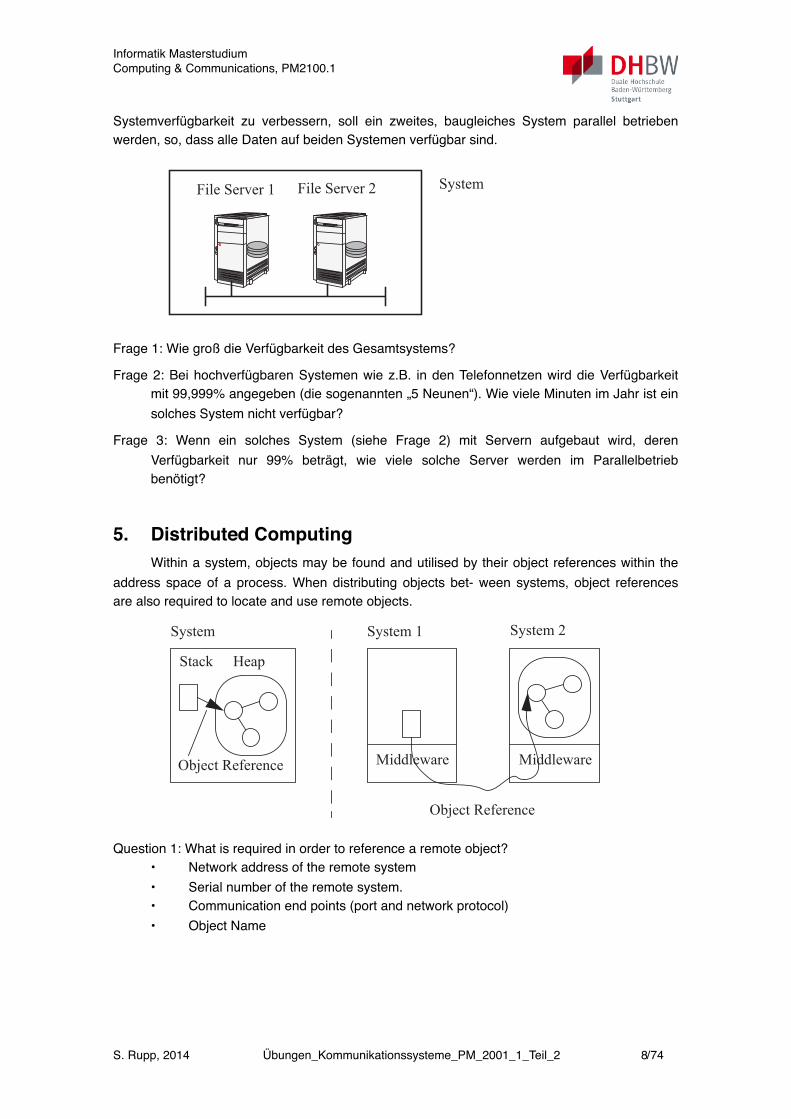
Systemverfügbarkeit zu verbessern, soll ein zweites, baugleiches System parallel betrieben werden, so, dass alle Daten auf beiden Systemen verfügbar sind.
7.1 Part One (Chapters 1, 3, and 6) 215
7 Exercises
Exercises are organised in two different levels with different dephts: Partone provides a basic level of exercises. For part one, lecture of chapter 1 (net-works), chapter 3 (distribution) and chapter 6 (security) is sufficient. Part twoof the exercises covers the whole book including the remaining chapters andrequires a deeper level of expertise.
7.1 Part One (Chapters 1, 3, and 6)
7.1.1 System Availability
An experimental system (file server) has an availability of 80%, i.e. the ave-rage down time is 20%. In order to improve the system availability, it is fore-seen to replicate the the data on a system of the same kind and to operate bothin parallel.
Question 1.1: What is the over all system availability after this measure?
Question 1.2: Systems in telecommunication networks are called “carriergrade” if their availability is better than 99,999%, i.e. their downtime isbelow one hour per year. In order to achieve this figure, how big needsthe availability of a single server to be in the replicated configurationshown above?
7.1.2 Mobile Terminating Call
When calling a mobile subscriber, the network elements communicate witheach other according to the scenario as shown in the figure. A mobile networkoperator is estimating the number of transactions and volume of data which isused for this procedure. Such an estimation represents a foundation for the bas-dimensioning of the network elements.
For his network, the network operator is using the following assumptions: - 50 million subscribers
File Server 1 File Server 2 System
Frage 1: Wie groß die Verfügbarkeit des Gesamtsystems?
Frage 2: Bei hochverfügbaren Systemen wie z.B. in den Telefonnetzen wird die Verfügbarkeit mit 99,999% angegeben (die sogenannten „5 Neunen“). Wie viele Minuten im Jahr ist ein solches System nicht verfügbar?
Frage 3: Wenn ein solches System (siehe Frage 2) mit Servern aufgebaut wird, deren Verfügbarkeit nur 99% beträgt, wie viele solche Server werden im Parallelbetrieb benötigt?
5. Distributed ComputingWithin a system, objects may be found and utilised by their object references within the
address space of a process. When distributing objects bet- ween systems, object references are also required to locate and use remote objects.
222 7 Exercises
Question 6.2: Describe a procedure, which makes the relation between userand service provider an anonymous one by using pseudonyms as Use-rIDs.
7.1.7 Distributed Computing
Within a system, objects may be found and utilised by their object refe-rences within the address space of a process. When distributing objects bet-ween systems, object references are also required to locate and use remote ob-jects.
Question 7.1: What is required in order to reference a remote object?
O Network address of the remote system
O Serial number of the remote system.
O Communication end points (port and network protocol)
O Object Name
GIS
Alice
Location Service Provider
Mobile Network Operator
whereIs(UserID)?
Request:
Response:
getLocation(UserID)
coordinates(UserID)
you are here
System
Stack Heap
Object Reference MiddlewareMiddleware
Object Reference
System 1 System 2
Question 1: What is required in order to reference a remote object? • Network address of the remote system• Serial number of the remote system.• Communication end points (port and network protocol)• Object Name
Informatik MasterstudiumComputing & Communications, PM2100.1
S. Rupp, 2014 Übungen_Kommunikationssysteme_PM_2001_1_Teil_2 8/74
!
7.1 Part One (Chapters 1, 3, and 6) 223
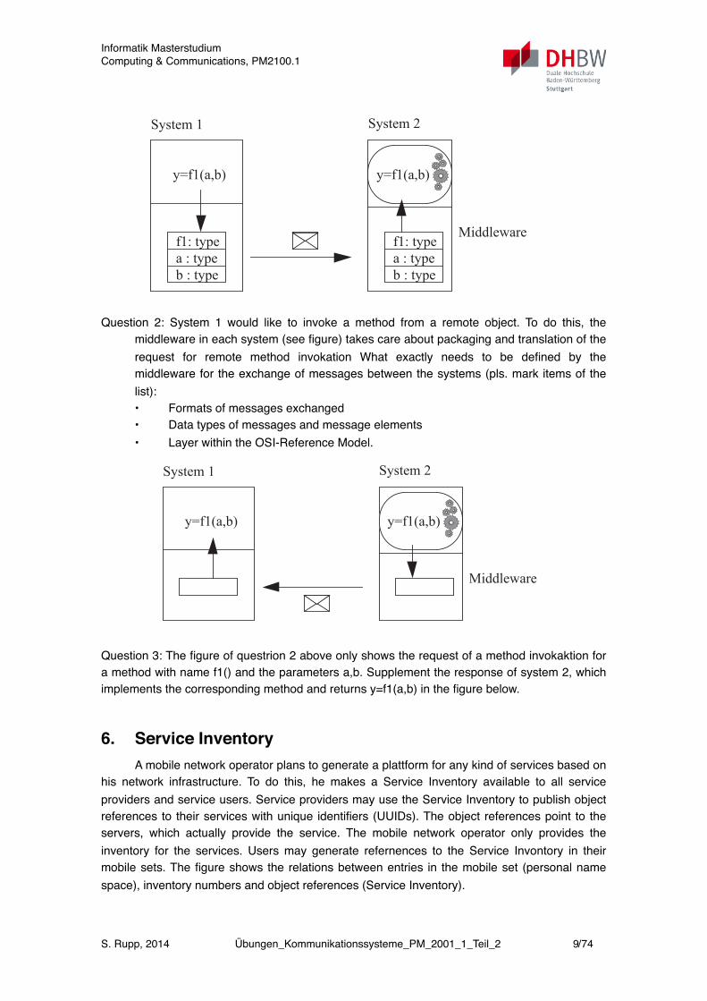
Question 7.2: System 1 would like to invoke a method from a remote object.To do this, the middleware in each system (see figure) takes care aboutpackaging and translation of the request for remote method invokationWhat exactly needs to be defined by the middleware for the exchange ofmessages between the systems (pls. mark items of the list):
O Formats of messages exchanged
O Data types of messages and message elements
O Layer within the OSI-Reference Model.
Question 7.3: The figure of questrion 7.2 above only shows the request of amethod invokaktion for a method with name f1() and the parameters a,b.Supplement the response of system 2, which implements the correspon-ding method and returns y=f1(a,b) in the figure below.
7.1.8 Service Inventory
A mobile network operator plans to generate a plattform for any kind of ser-vices based on his network infrastructure. To do this, he makes a Service In-ventory available to all service providers and service users. Service providersmay use the Service Inventory to publish object references to their serviceswith unique identifiers (UUIDs). The object references point to the servers,which actually provide the service. The mobile network operator only provi-
Middleware
System 1 System 2
y=f1(a,b) y=f1(a,b)
f1: typea : typeb : type
f1: typea : typeb : type
Middleware
System 1 System 2
y=f1(a,b) y=f1(a,b)
Question 2: System 1 would like to invoke a method from a remote object. To do this, the middleware in each system (see figure) takes care about packaging and translation of the request for remote method invokation What exactly needs to be defined by the middleware for the exchange of messages between the systems (pls. mark items of the list):• Formats of messages exchanged• Data types of messages and message elements • Layer within the OSI-Reference Model.
!
7.1 Part One (Chapters 1, 3, and 6) 223
Question 7.2: System 1 would like to invoke a method from a remote object.To do this, the middleware in each system (see figure) takes care aboutpackaging and translation of the request for remote method invokationWhat exactly needs to be defined by the middleware for the exchange ofmessages between the systems (pls. mark items of the list):
O Formats of messages exchanged
O Data types of messages and message elements
O Layer within the OSI-Reference Model.
Question 7.3: The figure of questrion 7.2 above only shows the request of amethod invokaktion for a method with name f1() and the parameters a,b.Supplement the response of system 2, which implements the correspon-ding method and returns y=f1(a,b) in the figure below.
7.1.8 Service Inventory
A mobile network operator plans to generate a plattform for any kind of ser-vices based on his network infrastructure. To do this, he makes a Service In-ventory available to all service providers and service users. Service providersmay use the Service Inventory to publish object references to their serviceswith unique identifiers (UUIDs). The object references point to the servers,which actually provide the service. The mobile network operator only provi-
Middleware
System 1 System 2
y=f1(a,b) y=f1(a,b)
f1: typea : typeb : type
f1: typea : typeb : type
Middleware
System 1 System 2
y=f1(a,b) y=f1(a,b)
Question 3: The figure of questrion 2 above only shows the request of a method invokaktion for a method with name f1() and the parameters a,b. Supplement the response of system 2, which implements the corresponding method and returns y=f1(a,b) in the figure below.
6. Service InventoryA mobile network operator plans to generate a plattform for any kind of services based on
his network infrastructure. To do this, he makes a Service Inventory available to all service providers and service users. Service providers may use the Service Inventory to publish object references to their services with unique identifiers (UUIDs). The object references point to the servers, which actually provide the service. The mobile network operator only provides the inventory for the services. Users may generate refernences to the Service Invontory in their mobile sets. The figure shows the relations between entries in the mobile set (personal name space), inventory numbers and object references (Service Inventory).
Informatik MasterstudiumComputing & Communications, PM2100.1
S. Rupp, 2014 Übungen_Kommunikationssysteme_PM_2001_1_Teil_2 9/74
Question 1: A service provider uses as object references the connectors of the Generic Connection Framework of the Java 2 Micro Edition (J2ME GCF). This kind of object reference includes network address, protocol, ports and object name in a generalised way into one string, which is handed as a parameter to a method, which opens a connection:
Connector.open("<Protocol>:<Address>;<Parameters>")
Some examples for the usage of the GCF connector:
(1) Connector.open("http://www.dhbw-stuttgart.de")
(2) Connector.open("socket://162.234.100.200:8090")
(3) Connector.open("comm:0;baudrate=9600")
(4) Connector.open("file:/hiScore.dat")
(5) Connector.open("phone:/+4917123456789")
Which of the examples from the list point to local references (pls. include a short explanation)?
Question 2 Another service provider is offering services based on Web-Services. What would this service provider use as object reference?
Question 3: One of the service providers offers remote chess as service. Alice and Bob may deposit their game of chess at a given UUID. The server of the service provider keeps track of the game and who’s turn it is. The mobile sets need a specific client application which matches the ser- ver application. Name some of the ways to provide such client applicati- ons for users.
Question 4: The local pharmacies would like to use the Inventory Server by entering a reference to the homepage of the respective pharmacy, which is on duty over night and during weekends. Describe, how this project may be implemented.
7. Names, Adresses und Identities
7.1 Part One (Chapters 1, 3, and 6) 225
which is on duty over night and during week-ends. Describe, how thisproject may be implemented.
7.1.9 Name, Address and Identity
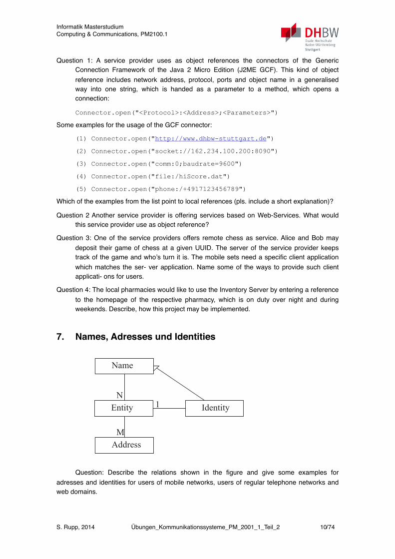
Question 9: Describe the relations shown in the figure and give some ex-amples for adresses and identities for users of mobile networks, users ofregular telephone networks and web domains.
7.1.10 Name Spaces
Name spaces may be represented as labelled, directed graphs. Followingthelabels of such a diagram results in path descriptions in this general form:
N:<label-1><label-2> ...<label-m>where N indicates the starting point (relative path) or the root of the name
graph. Such representations are familiar from directories in a file system. The graph shown in the following figure represents a hypothetical path in
the name space of the directory service X.500.
Name
Address
IdentityEntity 1N
M
C=DE
O = Uni Stuttgart
OU = Informatik
CN = Info_Server
Host_Name = GeminiHost_Name = Andromeda
C : CountryO : OrganisationOU : Organisation UnitCN : Common Name
Question: Describe the relations shown in the figure and give some examples for adresses and identities for users of mobile networks, users of regular telephone networks and web domains.
Informatik MasterstudiumComputing & Communications, PM2100.1
S. Rupp, 2014 Übungen_Kommunikationssysteme_PM_2001_1_Teil_2 10/74
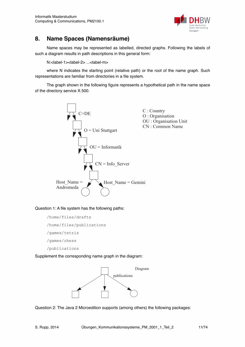
8. Name Spaces (Namensräume)Name spaces may be represented as labelled, directed graphs. Following the labels of
such a diagram results in path descriptions in this general form:
N:<label-1><label-2> ...<label-m>
where N indicates the starting point (relative path) or the root of the name graph. Such representations are familiar from directories in a file system.
The graph shown in the following figure represents a hypothetical path in the name space of the directory service X.500.
! !
!
7.1 Part One (Chapters 1, 3, and 6) 225
which is on duty over night and during week-ends. Describe, how thisproject may be implemented.
7.1.9 Name, Address and Identity
Question 9: Describe the relations shown in the figure and give some ex-amples for adresses and identities for users of mobile networks, users ofregular telephone networks and web domains.
7.1.10 Name Spaces
Name spaces may be represented as labelled, directed graphs. Followingthelabels of such a diagram results in path descriptions in this general form:
N:<label-1><label-2> ...<label-m>where N indicates the starting point (relative path) or the root of the name
graph. Such representations are familiar from directories in a file system. The graph shown in the following figure represents a hypothetical path in
the name space of the directory service X.500.
Name
Address
IdentityEntity 1N
M
C=DE
O = Uni Stuttgart
OU = Informatik
CN = Info_Server
Host_Name = GeminiHost_Name = Andromeda
C : CountryO : OrganisationOU : Organisation UnitCN : Common Name
Question 1: A file system has the following paths:
/home/files/drafts
/home/files/publications
/games/tetris
/games/chess
/publications
Supplement the corresponding name graph in the diagram:
!
226 7 Exercises
Question 10.1: A file system has the following paths:
/home/files/drafts
/home/files/publications
/games/tetris
/games/chess
/publications
Supplement the corresponding name graph in the diagram:
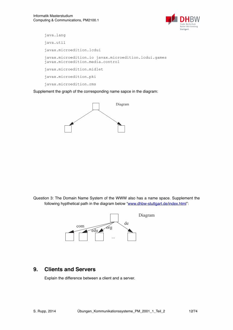
Question 10.2: The Java 2 Microedition supports (among others) the follo-wing packages:
java.lang
java.util
javax.microedition.lcdui
javax.microedition.io
javax.microedition.lcdui.games
javax.microedition.media.control
javax.microedition.midlet
javax.microedition.pki
javax.microedition.rms
Supplement the graph of the corresponding name sapce in the diagram:
publications
Diagram for question 10.1
Question 2: The Java 2 Microedition supports (among others) the following packages:
Informatik MasterstudiumComputing & Communications, PM2100.1
S. Rupp, 2014 Übungen_Kommunikationssysteme_PM_2001_1_Teil_2 11/74
java.lang
java.util
javax.microedition.lcdui
javax.microedition.io javax.microedition.lcdui.games javax.microedition.media.control
javax.microedition.midlet
javax.microedition.pki
javax.microedition.rms
Supplement the graph of the corresponding name sapce in the diagram:
! !
7.1 Part One (Chapters 1, 3, and 6) 227
Question 10.3: The Domain Name System of the WWW also has a namespace. Supplement the following hypthetical path in the diagram below“www.ikr.uni-stuttgart.de/index.html”:
7.1.11 CORBA and RMI
Diagram for Question 10.2
Diagram for Question 10.3
com orgedu
de
...
Question 3: The Domain Name System of the WWW also has a name space. Supplement the following hypthetical path in the diagram below “www.dhbw-stuttgart.de/index.html”:
! !
7.1 Part One (Chapters 1, 3, and 6) 227
Question 10.3: The Domain Name System of the WWW also has a namespace. Supplement the following hypthetical path in the diagram below“www.ikr.uni-stuttgart.de/index.html”:
7.1.11 CORBA and RMI
Diagram for Question 10.2
Diagram for Question 10.3
com orgedu
de
...
!
9. Clients and ServersExplain the difference between a client and a server.
Informatik MasterstudiumComputing & Communications, PM2100.1
S. Rupp, 2014 Übungen_Kommunikationssysteme_PM_2001_1_Teil_2 12/74
10. Threads and ProcessesThreads are flows of control within the address space of a process.
Question 1: What happens, when a violation of address space occurs within a thread?
Question 2: A part of the application is moved to a remote system. What happens, when a violation of the address space happens on the remote system?
11. Memory LeakA badly written application keeps allocating memory by generating objects without
eliminating all of them after they are not needed any more.
Question 1:The user of a desktop system which extends memory by a hard disk is running such an application and notices, that the system is continuously getting slower. Why?
Question 2: What would happen on a mobile phone (whithout a hard disk) in the same situation?
Question 3: The user of the deskttop system has learned to exit and re- start the application it this situation. How does this measure work?
12. Viruses and Trojan HorsesWhich kind of system allows to provide better protection against viruses and trojan
horses: a monotasking operating system or a multitasking operating system (pls. indicate the reason).
13. Service DiscoveryHow may a device discover services which are offered in a new environment and how
can the device offer own services? Describe some general ways and mechanisms.
14. BluetoothDescribe how Service Discovery with Bluetooth works in principle. Explain, how an
application which has been written by yourself may be discoverd on your device.
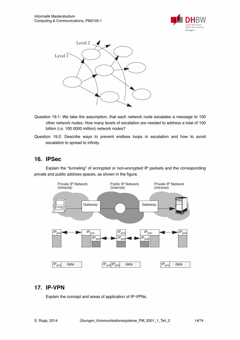
15. File-SharingAs shown in the figure, a file sharing network is organised in a way, that network nodes
may escalate a message that they have received to other known network nodes. The figure shows two levels of escalation.
Informatik MasterstudiumComputing & Communications, PM2100.1
S. Rupp, 2014 Übungen_Kommunikationssysteme_PM_2001_1_Teil_2 13/74
!
230 7 Exercises
As shown in the figure, a file sharing network is organised in a way, that net-work nodes may escalate a message that they have received to other knownnetwork nodes. The figure shows two levels of escalation.
Question 19.1: We take the assumption, that each network node escalates amessage to 100 other network nodes. How many levels of escalation areneeded to address a total of 100 billion (i.e. 100 0000 million) networknodes?
Question 19.2: Describe ways to prevent endless loops in escalation andhow to avoid escalation to spread to infinity.
7.1.20 CORBA and Web-Services
While using CORBA, a client-stub is compiled from a formal interface de-finition which is contained in an IDL-file. Name an equivalent formal descrip-tion of the interface with Web-Services.
7.1.21 Direct Provision of Client Applications
An alternative to the tedious procedure of generating client-stub for clientapplications from formal descriptions is to provide the complete client appli-cation for loading and installation on the target client system. Compare bothalternatives and indicate typical ares of application.
7.1.22 A Sandbox for Software
Explain the concept of a “sandbox” for loading and running software on asystem and describe some of the components of such a concept.
7.1.23 Buffer Overflow
Why are “buffer overflows” not occuring with Java programs?
Level 1
Level 2
Question 19.1: We take the assumption, that each network node escalates a message to 100 other network nodes. How many levels of escalation are needed to address a total of 100 billion (i.e. 100 0000 million) network nodes?
Question 19.2: Describe ways to prevent endless loops in escalation and how to avoid escalation to spread to infinity.
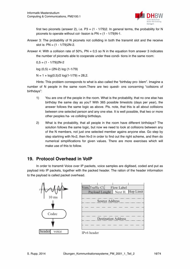
16. IPSecExplain the “tunneling” of ecnrypted or non-encrypted IP packets and the corresponding
private and public address spaces, as shown in the figure.
7.1 Part One (Chapters 1, 3, and 6) 233
streams shown in the figure. Supplement the figure.
Question 36.2 The procedure is considered as extremely difficult to attack(i.e. analyse and crack). Why is this?
Question 36.3: Do you recommend Alice and Bob to re-use the same ran-dom text several times? Explain your recommendation.
Question 36.4: Describe an appoximation of the procedure which utilisesthe same type of random text generator with Alice and Bob.
7.1.34 IPSec
Explain the “tunneling” of ecnrypted or non-encrypted IP packets and thecorresponding private and public address spaces, as shown in the figure.
7.1.35 IP-VPNs
Explain the concept and areas of application of IP-VPNs.
7.1.36 Identity, Authentication, Authorisation
Alice Bob
Plain Text: 0101 1001
Random Text: 1001 0111
Cipher Text
Random Text: 1001 0111
........................
GatewayGateway
Private IP Network(Intranet)
Private IP Network(Intranet)
Public IP Network(Internet)
IPpriv IPprivIPpriv IPpriv
IPpub IPpubIPpub
IPpriv
IPpriv data IPpriv dataIPpriv dataIPpub
17. IP-VPNExplain the concept and areas of application of IP-VPNs.
Informatik MasterstudiumComputing & Communications, PM2100.1
S. Rupp, 2014 Übungen_Kommunikationssysteme_PM_2001_1_Teil_2 14/74

18. Collisions in PiconetsWhile using the Bluetooth radio technology, devices may form piconets as shown in the
figure. All devices on one piconet communicate using frequency hopping over a total of 79 channels (channel 0 to 78). In each piconet, one master (M) determines the hopping sequence of its piconet with all slaves follo- wing this hopping sequence. Also, only one device within a piconet can transmit at the same time. Thus, there are no collisions of devices within one pico- net.
7.2 Part Two (Complete Book) 235
mit at the same time. Thus, there are no collisions of devices within one pico-net.
But what happens, if several piconets are operating in the same room and atthe same time? From the perspective of one given piconet, how many other pi-conets can operate in the same room for a given collission rate? The assump-tion is taken, that collisions happen every time, when any of the piconets in theroom happen to use the same channel, i.e. every piconet is able to interferewith each other piconet.
Question 1: What is the probability for 2 piconets to operate without collisi-ons? (Hint: Each piconet runs all 79 channels in random sequence, irrespectiveof the number of devices in the piconet. What is the probability that 2 piconetsincidently use the same channel? What is the probability of not colliding whenoperating two piconets?)
Question 2: What is the probability for not colloding when operting 3 pico-nets? Generalise the term for the collisionfree operation of N piconets.
Question 3: When a collision occurs, the packet is lost and will need to beretransmitted. The probability calculated so far just represents collision of oneslot. In Bluetooth, master and slaves use alternating slots for transmission, onecontaining confirmation of receipt. If the packet is lost during transmission, itwill need to be retransmitted. If the confirmation of receipt is lost in a collision,the packet will also be retransmitted. Adapt the probability for collisionfreeoperation accordingly.
Question 4: If we take the assumption, that collision rate (probability of col-lisions) of 50% is acceptable, how many (N) piconets can operate in the sameroom?
Answer 1: When 79 channels are used and piconet 1 is transmitting on oneof the channels (e.g channel 0), there is a 1 to 79 chance that piconet 2 is trans-mitting on the same channel at the same time. Thus, the probability for not col-liding between 2 piconets is: P2 = 1 - 1/79.
Answer 2:With 3 piconets, the chance that neither the second or third pico-net will collide with the first piconet corresponds to the chance, that the thirdpiconet will not collide with the first two piconets (answer 2), i.e. P3 = (1 -1/79)2. In general terms, the probability for N piconets to operate without col-lission is PN = (1 - 1/79)N-1.
Answer 3: The probability of N piconets not colliding in both the transmitslot and the receive slot is: PN = (1 - 1/79)2N-2.
Answer 4: With a collision rate of 50%, PN = 0,5 so N in the equation fromanswer 3 indicates the number of piconets able to cooperate under thee condi-tions in the same room:
0,5 = (1 - 1/79)2N-2
log (0,5) = (2N-2) log (1-1/79)
M M
M
But what happens, if several piconets are operating in the same room and at the same time? From the perspective of one given piconet, how many other pi- conets can operate in the same room for a given collission rate? The assump- tion is taken, that collisions happen every time, when any of the piconets in the room happen to use the same channel, i.e. every piconet is able to interfere with each other piconet.
Question 1: What is the probability for 2 piconets to operate without collisi- ons? (Hint: Each piconet runs all 79 channels in random sequence, irrespective of the number of devices in the piconet. What is the probability that 2 piconets incidently use the same channel? What is the probability of not colliding when operating two piconets?)
Question 2: What is the probability for not colloding when operting 3 pico- nets? Generalise the term for the collisionfree operation of N piconets.
Question 3: When a collision occurs, the packet is lost and will need to be retransmitted. The probability calculated so far just represents collision of one slot. In Bluetooth, master and slaves use alternating slots for transmission, one containing confirmation of receipt. If the packet is lost during transmission, it will need to be retransmitted. If the confirmation of receipt is lost in a collision, the packet will also be retransmitted. Adapt the probability for collisionfree operation accordingly.
Question 4: If we take the assumption, that collision rate (probability of col- lisions) of 50% is acceptable, how many (N) piconets can operate in the same room?
Answer 1: When 79 channels are used and piconet 1 is transmitting on one of the channels (e.g channel 0), there is a 1 to 79 chance that piconet 2 is trans- mitting on the same channel at the same time. Thus, the probability for not col- liding between 2 piconets is: P2 = 1 - 1/79.
Answer 2:With 3 piconets, the chance that neither the second or third pico- net will collide with the first piconet corresponds to the chance, that the third piconet will not collide with the
Informatik MasterstudiumComputing & Communications, PM2100.1
S. Rupp, 2014 Übungen_Kommunikationssysteme_PM_2001_1_Teil_2 15/74
first two piconets (answer 2), i.e. P3 = (1 - 1/79)2. In general terms, the probability for N piconets to operate without col- lission is PN = (1 - 1/79)N-1.
Answer 3: The probability of N piconets not colliding in both the transmit slot and the receive slot is: PN = (1 - 1/79)2N-2.
Answer 4: With a collision rate of 50%, PN = 0,5 so N in the equation from answer 3 indicates the number of piconets able to cooperate under thee condi- tions in the same room:
! 0,5 = (1 - 1/79)2N-2
! log (0,5) = (2N-2) log (1-1/79)
! N = 1 + log(0,5)/2 log(1-1/79) = 28,2.
Hints: This problem corresponds to what is also called the “birthday pro- blem”. Imagine a number of N people in the same room.There are two questi- ons concerning “collsions of birthdays”:
1) You are one of the people in the room. What is the probability, that no one else has birthday the same day as you? With 365 possible timeslots (days per year), the answer follows the same logic as above. Pls. note, that this is all about collisions between one selected person and any one else. It is well possible, that two or more other peoples ha- ve colliding birthdays.
2) What is the probability, that all people in the room have different birthdays? The solution follows the same logic, but now we need to look at collisions between any of the N members, not just one selected member agains anyone else. Go step by step startring with N=2, then N=3 in order to find out the right scheme, and then do numerical simplifications for given values. There are more exercises which will make use of this to follow.
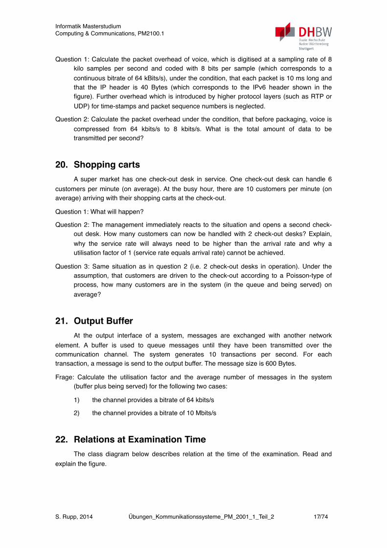
19. Protocol Overhead in VoIPIn order to transmit Voice over IP packets, voice samples are digitised, coded and put as
payload into IP packets, together with the packed header. The ration of the header information to the payload is called packet overhead.
7.2 Part Two (Complete Book) 239
In order to transmit Voice over IP packets, voice samples are digitised, co-ded and put as payload into IP packets, together with the packed header. Theration of the header information to the payload is called packet overhead.
Question 1: Calculate the packet overhead of voice, which is digitised at asampling rate of 8 kilo samples per second and coded with 8 bits per sample(which corresponds to a continuous bitrate of 64 kBits/s), under the condition,that each packet is 10 ms long and that the IP header is 40 Bytes (which cor-responds to the IPv6 header shown in the figure). Further overhead which isintroduced by higher protocol layers (such as RTP or UDP) for time-stampsand packet sequence numbers is neglected.
Question 2: Calculate the packet overhead under the condition, that beforepackaging, voice is compressed from 64 kbits/s to 8 kbits/s. What is the totalamount of data to be transmitted per second?
7.2.4 Shopping carts
A super market has one check-out desk in service. One check-out desk canhandle 6 customers per minute (on average). At the busy hour, there are 10customers per minute (on average) arriving with their shopping carts at thecheck-out.
Question 1: What will happen?Question 2: The management immediately reacts to the situation and opens
a second check-out desk. How many customers can now be handled with 2check-out desks? Explain, why the service rate will always need to be higherthan the arrival rate and why a utilisation factor of 1 (service rate equals arrivalrate) cannot be achieved.
Question 3: Same situation as in question 2 (i.e. 2 check-out desks in opera-tion). Under the assumption, that customers are driven to the check-out accor-ding to a Poisson-type of process, how many customers are in the system (inthe queue and being served) on average?
7.2.5 Output Buffer
At the output interface of a system, messages are exchanged with anothernetwork element. A buffer is used to queue messages until they have been
Codec
10 ms
voiceheader
Vers.Traffic Cl. Flow LabelPayload Lenght Next H. Hop Limit
Source Address
Destination Address
IPv6 header
Informatik MasterstudiumComputing & Communications, PM2100.1
S. Rupp, 2014 Übungen_Kommunikationssysteme_PM_2001_1_Teil_2 16/74
Question 1: Calculate the packet overhead of voice, which is digitised at a sampling rate of 8 kilo samples per second and coded with 8 bits per sample (which corresponds to a continuous bitrate of 64 kBits/s), under the condition, that each packet is 10 ms long and that the IP header is 40 Bytes (which corresponds to the IPv6 header shown in the figure). Further overhead which is introduced by higher protocol layers (such as RTP or UDP) for time-stamps and packet sequence numbers is neglected.
Question 2: Calculate the packet overhead under the condition, that before packaging, voice is compressed from 64 kbits/s to 8 kbits/s. What is the total amount of data to be transmitted per second?
20. Shopping cartsA super market has one check-out desk in service. One check-out desk can handle 6
customers per minute (on average). At the busy hour, there are 10 customers per minute (on average) arriving with their shopping carts at the check-out.
Question 1: What will happen?
Question 2: The management immediately reacts to the situation and opens a second check-out desk. How many customers can now be handled with 2 check-out desks? Explain, why the service rate will always need to be higher than the arrival rate and why a utilisation factor of 1 (service rate equals arrival rate) cannot be achieved.
Question 3: Same situation as in question 2 (i.e. 2 check-out desks in operation). Under the assumption, that customers are driven to the check-out according to a Poisson-type of process, how many customers are in the system (in the queue and being served) on average?
21. Output BufferAt the output interface of a system, messages are exchanged with another network
element. A buffer is used to queue messages until they have been transmitted over the communication channel. The system generates 10 transactions per second. For each transaction, a message is send to the output buffer. The message size is 600 Bytes.
Frage: Calculate the utilisation factor and the average number of messages in the system (buffer plus being served) for the following two cases:
1) the channel provides a bitrate of 64 kbits/s
2) the channel provides a bitrate of 10 Mbits/s
22. Relations at Examination TimeThe class diagram below describes relation at the time of the examination. Read and
explain the figure.
Informatik MasterstudiumComputing & Communications, PM2100.1
S. Rupp, 2014 Übungen_Kommunikationssysteme_PM_2001_1_Teil_2 17/74

242 7 Exercises
The class diagram below describes relation at the time of the examination.Read and explain the figure.
More specifically, the examination for Telecommunication Software Engi-neering will look like this:
7.2.11 Evaluation of Results
Following examination, the results are evaluated by the teacher and madeavailable to the students by using the immatriculation numbers as reference.Also the overall results (average, standard deviation) are evaluated and made
Examination
+time+date+location
terminate()
Participant
+name
Student
-immatriculno: int-confident: boolean
think()
write()
terminate()
Teacher
Task
+titel
Question
+questionno
*
takes part
writes
solves
*
Generalisation
Aggregation (“has a”)
Composition
Association+date
+text
(“is a”)
Problem
+number+text
*
Task
+titel
Question
+questionno2
+date+text
Problem
+number+text
*
{< 8}
More specifically, the examination for Telecommunication Engineering will look like this:
242 7 Exercises
The class diagram below describes relation at the time of the examination.Read and explain the figure.
More specifically, the examination for Telecommunication Software Engi-neering will look like this:
7.2.11 Evaluation of Results
Following examination, the results are evaluated by the teacher and madeavailable to the students by using the immatriculation numbers as reference.Also the overall results (average, standard deviation) are evaluated and made
Examination
+time+date+location
terminate()
Participant
+name
Student
-immatriculno: int-confident: boolean
think()
write()
terminate()
Teacher
Task
+titel
Question
+questionno
*
takes part
writes
solves
*
Generalisation
Aggregation (“has a”)
Composition
Association+date
+text
(“is a”)
Problem
+number+text
*
Task
+titel
Question
+questionno2
+date+text
Problem
+number+text
*
{< 8}
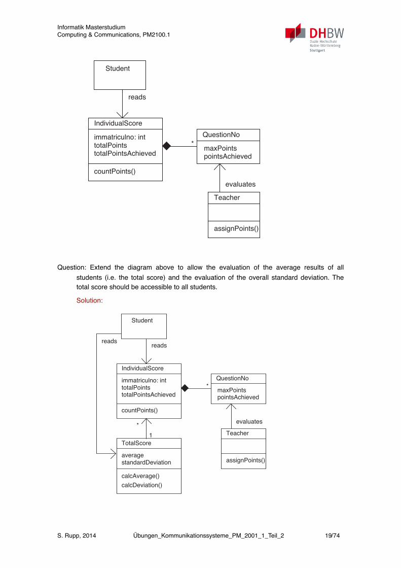
23. Evaluation of ResultsFollowing examination, the results are evaluated by the teacher and made available to
the students by using the immatriculation numbers as reference. Also the overall results (average, standard deviation) are evaluated and made available, so everone may find out his individual position in the results. The corresponding classes and relations are shown in the figure.
Informatik MasterstudiumComputing & Communications, PM2100.1
S. Rupp, 2014 Übungen_Kommunikationssysteme_PM_2001_1_Teil_2 18/74
7.2 Part Two (Complete Book) 243
available, so everone may find out his individual position in the results. Thecorresponding classes and relations are shown in the figure.
Question 1: Extend the diagram above to allow the evaluation of the averageresults of all students (i.e. the total score) and the evaluation of the overall stan-dard deviation. The total score should be accessible to all students.
Solution:
Question 2: The diagram above represents a class diagram. Show the relati-ons between the IndividualScore, TotalScore and QuestionNo in an object di-agram with instances for 3 students (with imatriculation numbers 37, 56, and89) and 2 questions (QuestionNo) per IndividualScore.
Student
IndividualScore
immatriculno: inttotalPoints
countPoints()
QuestionNo
Teacher
assignPoints()
*
totalPointsAchievedmaxPointspointsAchieved
evaluates
reads
Student
IndividualScore
immatriculno: inttotalPoints
countPoints()
QuestionNo
Teacher
assignPoints()
*
totalPointsAchievedmaxPointspointsAchieved
evaluates
reads
TotalScore
averagestandardDeviation
calcDeviation()
*
1
calcAverage()
reads
Question: Extend the diagram above to allow the evaluation of the average results of all students (i.e. the total score) and the evaluation of the overall standard deviation. The total score should be accessible to all students.
Solution:
7.2 Part Two (Complete Book) 243
available, so everone may find out his individual position in the results. Thecorresponding classes and relations are shown in the figure.
Question 1: Extend the diagram above to allow the evaluation of the averageresults of all students (i.e. the total score) and the evaluation of the overall stan-dard deviation. The total score should be accessible to all students.
Solution:
Question 2: The diagram above represents a class diagram. Show the relati-ons between the IndividualScore, TotalScore and QuestionNo in an object di-agram with instances for 3 students (with imatriculation numbers 37, 56, and89) and 2 questions (QuestionNo) per IndividualScore.
Student
IndividualScore
immatriculno: inttotalPoints
countPoints()
QuestionNo
Teacher
assignPoints()
*
totalPointsAchievedmaxPointspointsAchieved
evaluates
reads
Student
IndividualScore
immatriculno: inttotalPoints
countPoints()
QuestionNo
Teacher
assignPoints()
*
totalPointsAchievedmaxPointspointsAchieved
evaluates
reads
TotalScore
averagestandardDeviation
calcDeviation()
*
1
calcAverage()
reads
Informatik MasterstudiumComputing & Communications, PM2100.1
S. Rupp, 2014 Übungen_Kommunikationssysteme_PM_2001_1_Teil_2 19/74
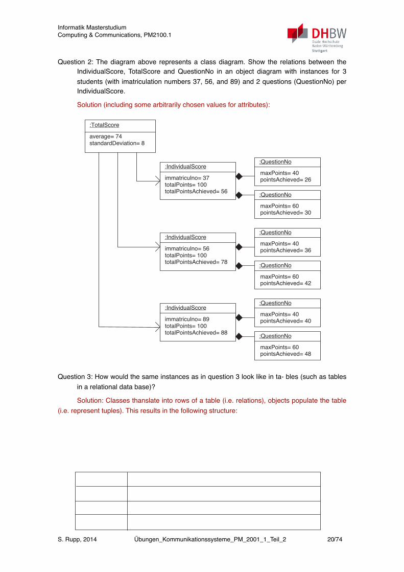
Question 2: The diagram above represents a class diagram. Show the relations between the IndividualScore, TotalScore and QuestionNo in an object diagram with instances for 3 students (with imatriculation numbers 37, 56, and 89) and 2 questions (QuestionNo) per IndividualScore.
Solution (including some arbitrarily chosen values for attributes):
244 7 Exercises
Solution (including some arbitrarily chosen values for attributes):
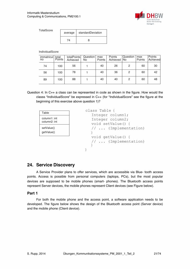
Question 3: How would the same instances as in question 3 look like in ta-bles (such as tables in a relational data base)?
Solution: Classes thanslate into rows of a table (i.e. relations), objects popu-late the table (i.e. represent tuples). This results in the following structure:
Question 4: In C++ a class can be represented in code as shown in the figure.
:IndividualScore
immatriculno= 37totalPoints= 100
:QuestionNo
totalPointsAchieved= 56
maxPoints= 40pointsAchieved= 26
:TotalScore
average= 74standardDeviation= 8
:QuestionNo
maxPoints= 60pointsAchieved= 30
:IndividualScore
immatriculno= 56totalPoints= 100
:QuestionNo
totalPointsAchieved= 78
maxPoints= 40pointsAchieved= 36
:QuestionNo
maxPoints= 60pointsAchieved= 42
:IndividualScore
immatriculno= 89totalPoints= 100
:QuestionNo
totalPointsAchieved= 88
maxPoints= 40pointsAchieved= 40
:QuestionNo
maxPoints= 60pointsAchieved= 48
TotalScoreaverage standardDeviation
74 8
IndividualScore
immatricul total
74 100
totalPoints Question max PointsAchieved No Points Achievedno Points
Question max PointsNo Points Achieved
56
89
100
100
56
78
88
1
1
1
40
40
40
26
36
40
2
2
2
60
60
60
30
42
48
Question 3: How would the same instances as in question 3 look like in ta- bles (such as tables in a relational data base)?
Solution: Classes thanslate into rows of a table (i.e. relations), objects populate the table (i.e. represent tuples). This results in the following structure:
Informatik MasterstudiumComputing & Communications, PM2100.1
S. Rupp, 2014 Übungen_Kommunikationssysteme_PM_2001_1_Teil_2 20/74
244 7 Exercises
Solution (including some arbitrarily chosen values for attributes):
Question 3: How would the same instances as in question 3 look like in ta-bles (such as tables in a relational data base)?
Solution: Classes thanslate into rows of a table (i.e. relations), objects popu-late the table (i.e. represent tuples). This results in the following structure:
Question 4: In C++ a class can be represented in code as shown in the figure.
:IndividualScore
immatriculno= 37totalPoints= 100
:QuestionNo
totalPointsAchieved= 56
maxPoints= 40pointsAchieved= 26
:TotalScore
average= 74standardDeviation= 8
:QuestionNo
maxPoints= 60pointsAchieved= 30
:IndividualScore
immatriculno= 56totalPoints= 100
:QuestionNo
totalPointsAchieved= 78
maxPoints= 40pointsAchieved= 36
:QuestionNo
maxPoints= 60pointsAchieved= 42
:IndividualScore
immatriculno= 89totalPoints= 100
:QuestionNo
totalPointsAchieved= 88
maxPoints= 40pointsAchieved= 40
:QuestionNo
maxPoints= 60pointsAchieved= 48
TotalScoreaverage standardDeviation
74 8
IndividualScore
immatricul total
74 100
totalPoints Question max PointsAchieved No Points Achievedno Points
Question max PointsNo Points Achieved
56
89
100
100
56
78
88
1
1
1
40
40
40
26
36
40
2
2
2
60
60
60
30
42
48
Question 4: In C++ a class can be represented in code as shown in the figure. How would the classs “IndividualScore” be expressed in C++ (for “IndividualScore” see the figure at the beginning of this exercise above question 1)?
7.2 Part Two (Complete Book) 245
How would the classs “IndividualScore” be expressed in C++ (for “Indivi-
dualScore” see the figure at the beginning of this exercise above question 1)?
7.2.12 Service Discovery
A Service Provider plans to offer services, which are accessible via Blue-tooth access points. Access is possible from personal computers (laptops,PCs), but the most popular devices are supposed to be mobile phones (smart-phones). The Bluetooth access points represent Server devices, the mobilephones represent Client devices (see Figure below).
Part 1
For both the mobile phone and the access point, a software application needsto be developed. The figure below shows the design of the Bluetooth accesspoint (Server device) and the mobile phone (Client device).
Question 1: Explain the components of the Server device and the Client de-vice (i.e. their function and how they interact). Note: SDP: Service Dis-
Table
column1: intcolumn2: int
getValue()
setValue()
class Table {
Integer column1;
Integer column2;
void setValue() {
// ... (Implementation)
}
void getValue() {
// ... (Implementation)}
}
Server device
SDP server
SDDB
Service record
Bluetooth stack
Server application
Serviceregistration
Client device
SDP client
Bluetooth stack
Client application
Servicediscovery
Serviceaccess
ServiceDiscoveryProtocol
24. Service DiscoveryA Service Provider plans to offer services, which are accessible via Blue- tooth access
points. Access is possible from personal computers (laptops, PCs), but the most popular devices are supposed to be mobile phones (smart- phones). The Bluetooth access points represent Server devices, the mobile phones represent Client devices (see Figure below).
Part 1For both the mobile phone and the access point, a software application needs to be
developed. The figure below shows the design of the Bluetooth access point (Server device) and the mobile phone (Client device).
Informatik MasterstudiumComputing & Communications, PM2100.1
S. Rupp, 2014 Übungen_Kommunikationssysteme_PM_2001_1_Teil_2 21/74

7.2 Part Two (Complete Book) 245
How would the classs “IndividualScore” be expressed in C++ (for “Indivi-
dualScore” see the figure at the beginning of this exercise above question 1)?
7.2.12 Service Discovery
A Service Provider plans to offer services, which are accessible via Blue-tooth access points. Access is possible from personal computers (laptops,PCs), but the most popular devices are supposed to be mobile phones (smart-phones). The Bluetooth access points represent Server devices, the mobilephones represent Client devices (see Figure below).
Part 1
For both the mobile phone and the access point, a software application needsto be developed. The figure below shows the design of the Bluetooth accesspoint (Server device) and the mobile phone (Client device).
Question 1: Explain the components of the Server device and the Client de-vice (i.e. their function and how they interact). Note: SDP: Service Dis-
Table
column1: intcolumn2: int
getValue()
setValue()
class Table {
Integer column1;
Integer column2;
void setValue() {
// ... (Implementation)
}
void getValue() {
// ... (Implementation)}
}
Server device
SDP server
SDDB
Service record
Bluetooth stack
Server application
Serviceregistration
Client device
SDP client
Bluetooth stack
Client application
Servicediscovery
Serviceaccess
ServiceDiscoveryProtocol
Question 1: Explain the components of the Server device and the Client de- vice (i.e. their function and how they interact). Note: SDP: Service Discovery Protocol, SDDB: Service Discovery Data Base.
Question 2: Indicate the sequence, in which the Server application and Cli- ent application use the functions which are provided by the Bluetooth stack and explain why this sequence is used.
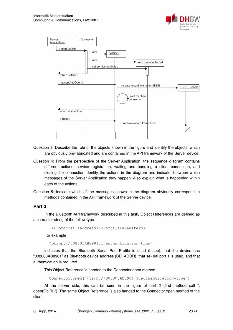
Part 2The figure below shows the life cycle of a Service Record on the Service Discovery Data
Base (SDDB). The Server Application controls the complete process. The Service Record is generated by a pre-fabricated method of the Connector type of object, and is finally written to the SDDB.
Informatik MasterstudiumComputing & Communications, PM2100.1
S. Rupp, 2014 Übungen_Kommunikationssysteme_PM_2001_1_Teil_2 22/74
246 7 Exercises
covery Protocol, SDDB: Service Discovery Data Base.
Question 2: Indicate the sequence, in which the Server application and Cli-ent application use the functions which are provided by the Bluetoothstack and explain why this sequence is used.
Part 2
The figure below shows the life cycle of a Service Record on the ServiceDiscovery Data Base (SDDB). The Server Application controls the completeprocess. The Service Record is generated by a pre-fabricated method of theConnector type of object, and is finally written to the SDDB.
Question 3: Describe the role of the objects shown in the figure and identifythe objects, which are obviously pre-fabricated and are contained in theAPI framework of the Server device.
Question 4: From the perspective of the Server Application, the sequencediagram contains different actions: service registration, waiting andhandling a client connection, and closing the connection.Identify the ac-tions in the diagram and indicate, between which messages of the ServerApplication they happen. Also explain what is happening within each ofthe actions.
Question 5: Indicate which of the messages shown in the diagram obviouslycorrespond to methods contained in the API framework of the Server de-vice.
: Connector
: open(ObjRf)
ServerApplication :
notifier :
rec : ServiceRecord
: SDDBRecord
: new
: new
return notifier :
: acceptAndOpen()
: set service attributes
: create record like rec in SDDB
: wait for clientconnection
return connection :
: close()
: remove record from SDDB
Question 3: Describe the role of the objects shown in the figure and identify the objects, which are obviously pre-fabricated and are contained in the API framework of the Server device.
Question 4: From the perspective of the Server Application, the sequence diagram contains different actions: service registration, waiting and handling a client connection, and closing the connection.Identify the actions in the diagram and indicate, between which messages of the Server Application they happen. Also explain what is happening within each of the actions.
Question 5: Indicate which of the messages shown in the diagram obviously correspond to methods contained in the API framework of the Server device.
Part 3In the Bluetooth API framework described in this task, Object References are defined as
a character string of the follow type:
“<Protocol>:<Address>:<Port>;<Parameters>”
For example
“btspp://008003AB8901:1;authentication=true”
indicates that the Bluetooth Serial Port Profile is used (btspp), that the device has “008003AB8901” as Bluetooth device address (BD_ADDR), that se- rial port 1 is used, and that authentication is required.
This Object Reference is handed to the Connector.open method:
Connector.open(“btspp://008003AB8901:1;authentication=true”)
At the server side, this can be seen in the figure of part 2 (first method call “: open(ObjRf)”). The same Object Reference is also handed to the Connector.open method of the client.
Informatik MasterstudiumComputing & Communications, PM2100.1
S. Rupp, 2014 Übungen_Kommunikationssysteme_PM_2001_1_Teil_2 23/74
Question 6: Explain the purpose of handing the Object Reference to the Connector.open method at the server side and at the client side.
Part 4After the client has succeded in connecting to the server and to invoke the Server
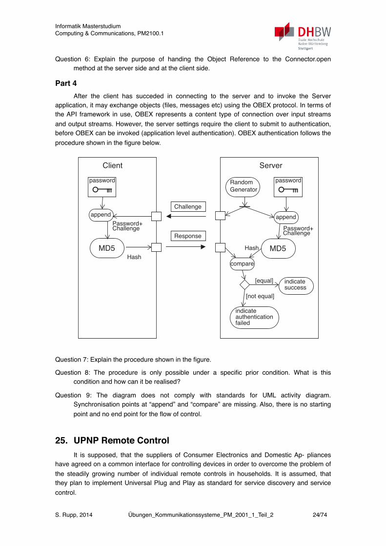
application, it may exchange objects (files, messages etc) using the OBEX protocol. In terms of the API framework in use, OBEX represents a content type of connection over input streams and output streams. However, the server settings require the client to submit to authentication, before OBEX can be invoked (application level authentication). OBEX authentication follows the procedure shown in the figure below.
248 7 Exercises
However, the server settings require the client to submit to authentication,before OBEX can be invoked (application level authentication). OBEX au-thentication follows the procedure shown in the figure below.
Question 7: Explain the procedure shown in the figure.
Question 8: The procedure is only possible under a specific prior condition.What is this condition and how can it be realised?
Question 9: The diagram does not comply with standards for UML activitydiagram. Synchronisation points at “append” and “compare” are mis-sing. Also, there is no starting point and no end point for the flow of con-trol. Change the figure to comply with UML standards.
7.2.13 Personal Networks
A Service Provider plans to offer Personal Network Services. The servicesshould enable service subscribers to connect devices from their personal envi-ronment to a Personal Network and to access their Personal Network fromanywhere.
Access is possible from personal computers (laptops, PCs), but the most po-pular device is supposed to be a mobile phone (smart phone). For mobile pho-nes, the Service Provider plans to use Bluetooth access points (or Access Gate-ways, AGW).
The network is an “ad-hoc” type of network, i.e. it allows to discover de-vices and services which are connected for the time being. For a user of thePersonal Network, this means, that the user may detect a network access point,and the access point transfers to the user’s device a choice of services, whichare available. Within the system, services are identified by ServiceIDs. Also,
Client
Hash
password
Password+Challenge
Server
Hash
password
MD5
Password+Challenge
Random
Generator
Challenge
Response
MD5
append append
compare
[equal]
[not equal]
indicate success
indicate authenticationfailed
Question 7: Explain the procedure shown in the figure.
Question 8: The procedure is only possible under a specific prior condition. What is this condition and how can it be realised?
Question 9: The diagram does not comply with standards for UML activity diagram. Synchronisation points at “append” and “compare” are missing. Also, there is no starting point and no end point for the flow of control.
25. UPNP Remote ControlIt is supposed, that the suppliers of Consumer Electronics and Domestic Ap- pliances
have agreed on a common interface for controlling devices in order to overcome the problem of the steadily growing number of individual remote controls in households. It is assumed, that they plan to implement Universal Plug and Play as standard for service discovery and service control.
Informatik MasterstudiumComputing & Communications, PM2100.1
S. Rupp, 2014 Übungen_Kommunikationssysteme_PM_2001_1_Teil_2 24/74
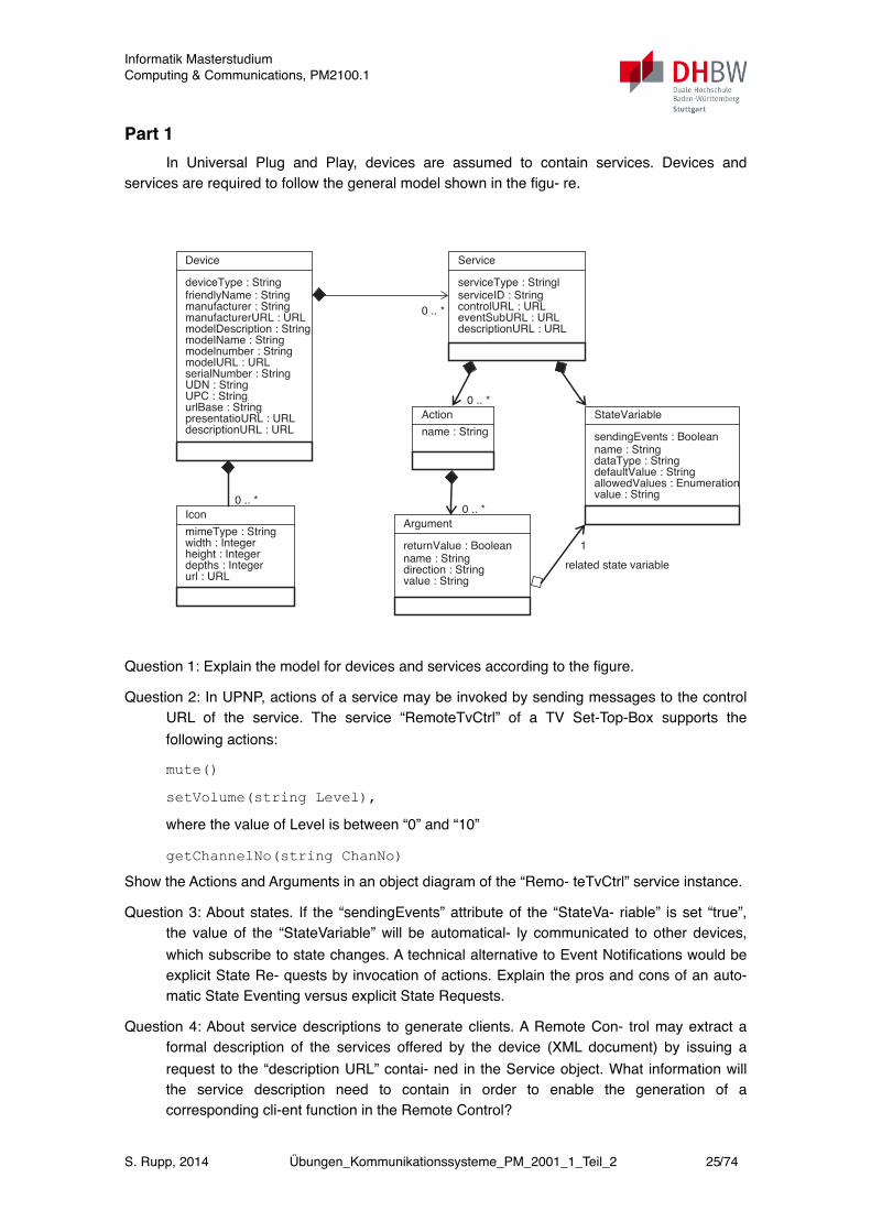
Part 1In Universal Plug and Play, devices are assumed to contain services. Devices and
services are required to follow the general model shown in the figu- re.
254 7 Exercises
7.2.15 UPNP Remote Control
It is supposed, that the suppliers of Consumer Electronics and Domestic Ap-pliances have agreed on a common interface for controlling devices in order toovercome the problem of the steadily growing number of individual remotecontrols in households. It is assumed, that they plan to implement UniversalPlug and Play as standard for service discovery and service control.
Part 1
In Universal Plug and Play, devices are assumed to contain services. De-vices and services are required to follow the general model shown in the figu-re.
Question 1: Explain the model for devices and services according to the fi-gure.
Question 2: In UPNP, actions of a service may be invoked by sending mes-sages to the control URL of the service. The service “RemoteTvCtrl” ofa TV Set-Top-Box supports the following actions:
(1) mute()
(2) setVolume(string Level), where the value of Level is bet-ween “0” and “10”
(3) getChannelNo(string ChanNo)
Device
deviceType : StringfriendlyName : String
Action
name : String
0 .. *manufacturer : StringmanufacturerURL : URLmodelDescription : StringmodelName : Stringmodelnumber : StringmodelURL : URLserialNumber : StringUDN : StringUPC : StringurlBase : StringpresentatioURL : URLdescriptionURL : URL
Service
serviceType : StringlserviceID : StringcontrolURL : URLeventSubURL : URLdescriptionURL : URL
Argument
returnValue : Booleanname : Stringdirection : Stringvalue : String
StateVariable
sendingEvents : Booleanname : StringdataType : StringdefaultValue : StringallowedValues : Enumerationvalue : String
Icon
mimeType : Stringwidth : Integerheight : Integerdepths : Integerurl : URL
0 .. *
0 .. *
0 .. *
1
related state variable
Question 1: Explain the model for devices and services according to the figure.
Question 2: In UPNP, actions of a service may be invoked by sending messages to the control URL of the service. The service “RemoteTvCtrl” of a TV Set-Top-Box supports the following actions:
mute()
setVolume(string Level),
where the value of Level is between “0” and “10”
getChannelNo(string ChanNo)
Show the Actions and Arguments in an object diagram of the “Remo- teTvCtrl” service instance.
Question 3: About states. If the “sendingEvents” attribute of the “StateVa- riable” is set “true”, the value of the “StateVariable” will be automatical- ly communicated to other devices, which subscribe to state changes. A technical alternative to Event Notifications would be explicit State Re- quests by invocation of actions. Explain the pros and cons of an auto- matic State Eventing versus explicit State Requests.
Question 4: About service descriptions to generate clients. A Remote Con- trol may extract a formal description of the services offered by the device (XML document) by issuing a request to the “description URL” contai- ned in the Service object. What information will the service description need to contain in order to enable the generation of a corresponding cli-ent function in the Remote Control?
Informatik MasterstudiumComputing & Communications, PM2100.1
S. Rupp, 2014 Übungen_Kommunikationssysteme_PM_2001_1_Teil_2 25/74

Part 2When a device enters a new environment, it needs to perform Service Dis- covery in
order to find other devices. In UPNP, the device gets a network address (e.g. by DHCP), then sends a multicast discovery message to the net- work and waits for responses. In order to avoid collisions by having other de- vices reply at the same time, the device sends a time interval with its Discovery Requests. Other devices answer within this interval at a randomly chosen point of time. It is planned to use UPNP discovery for wireless devices (e.g. infrared or Bluetooth) which operate over 10 kbits/s interfaces. Discovery response mes- sages are 500 Bytes.
Question 5: Calculate the length T of the time interval for responses, which is needed for a collissionfree operation of Pno-coll=0,9 for a number of 10 devices.
Question 6: When a new device enters a UPNP network, it also multicasts a presence notification which includes the advertisment of its services. Ex- plain the difference between issuing service discovery requests and issu- ing such presence notifications. Indicate, whether there is a useful combination of both methods.
Part 3With UPNP, the interface of a service contained in a device is specified in a service
description, which may be read from the service as an XML document. From this formal description of the server interface, a client function may be generated for the UPNP Remote Control. The figure on the left shows the relations between client, server and the interface. This relation may also be expressed as shown in the class diagram on the right.
256 7 Exercises
The figure on the left shows the relations between client, server and the in-terface. This relation may also be expressed as shown in the class diagram onthe right.
Question 7: Explain this relation.
Part 4
Using a UPNP Remote Control in a domestic environment generates secu-rity issues.
Question 8: Indicate some of the issues and describe adequate potential so-lutions.
7.2.16 Location Based Services
Client
Server
ServerInterface
Server
Client
ServerInterface
<<interface>>
ServerInterface
<<interface>>use
Question 7: Explain this relation.
Part 4Using a UPNP Remote Control in a domestic environment generates security issues.
Question 8: Indicate some of the issues and describe adequate potential so- lutions.
26. Client-Server CommunicationClient and Server of an application communicate with each other using SOAP as protocol
framework. SOAP is agnostic of the supporting protocol (it binds to it and is aware of its proper- ties), but does not depend on it (i.e. the supporting protocol may be exchanged).
Informatik MasterstudiumComputing & Communications, PM2100.1
S. Rupp, 2014 Übungen_Kommunikationssysteme_PM_2001_1_Teil_2 26/74
! !
7.2 Part Two (Complete Book) 259
The Mobile Network Operator has a view of the true identities of users anddevices.The figure below descibes the authentication procedure in GSM.
Question 7: Explain the procedure and discuss the protection it providesagainst potential attacks.
Question 8: The Provider of the Location Based Service in this task has alimited visibility of the identity of his users: users register with nickna-mes (pseudonyms). Also, user locations are communicated by pseudo-nyms (my shop, my pub). Discuss privacy issues with Location BasedServices in general and how this design of Location Based Serviceshandles these issues.
7.2.17 Client-Server Communication
Part 1
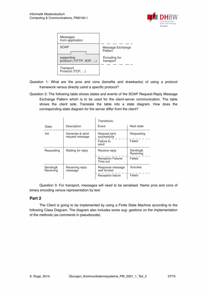
Client and Server of an applica-tion communicate with eachother using SOAP as protocolframework. SOAP is agnostic ofthe supporting protocol (it bindsto it and is aware of its proper-ties), but does not depend on it(i.e. the supporting protocol maybe exchanged).
Question 1: What are the pros and cons (benefits and drawbacks) of using aprotocol framework versus directly usind a specific protocol?
Question 2: The following table shows states and events of the SOAP Re-quest-Reply Message Exchange Pattern which is to be used for the cli-ent-server communication. The table shows the client side. Translate thetable into a state diagram. How does the corresponding state diagram for
GSM Network (HLR/AuC)
A3
private
Random
Mobile Set (SIM card)
Generator
Number
(Challenge)
Kiprivate
KiChallenge
A3
=
equal?
Response Response
Messagesfrom application
SOAP
supporting
TransportProtocol (TCP, ...)
protocol ( HTTP, IIOP, ...)
Message Exchange
Encoding for
Pattern
transport
Question 1: What are the pros and cons (benefits and drawbacks) of using a protocol framework versus directly usind a specific protocol?
Question 2: The following table shows states and events of the SOAP Request-Reply Message Exchange Pattern which is to be used for the client-server communication. The table shows the client side. Translate the table into a state diagram. How does the corresponding state diagram for the server differ from the client?
!
260 7 Exercises
the server differ from the client?
Question 3: For transport, messages will need to be serialised. Name prosand cons of binary encoding versus representation by text.
Part 2
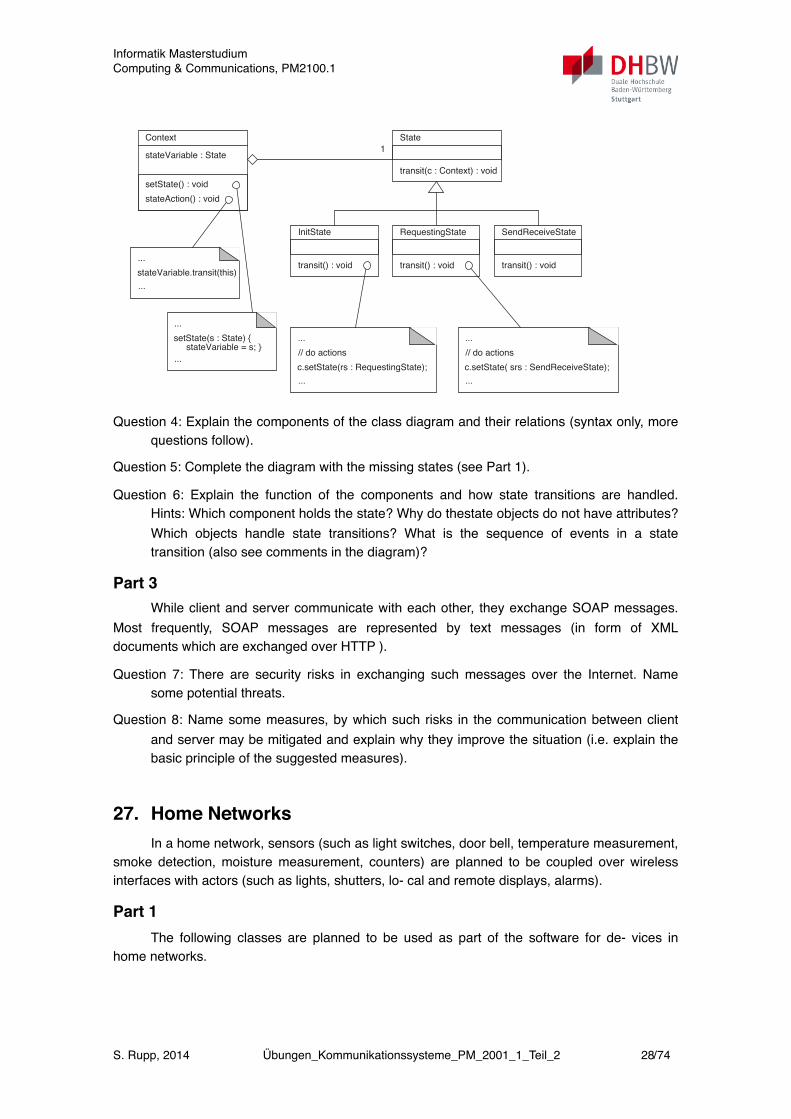
The Client is going to be implemented by using a Finite State Machine ac-cording to the following Class Diagram. The diagram also includes some sug-gestions on the implementation of the methods (as comments in pseudocode).
Question 4: Explain the components of the class diagram and their relations(syntax only, more questions follow).
Question 5: Complete the diagram with the missing states (see Part 1).
Question 6: Explain the function of the components and how state transiti-ons are handled. Hints: Which component holds the state? Why do the
State Description
Transitions:
Event Next state
Init Generate & send Request sent Requesting
Requesting Waiting for reply Receive reply Sending&
Sending& Receiving reply Response message SuccessReceiving
request message
message
successfully
Failure to Failedsend
Reception Failure/Time out
Receiving
Failed
Reception failure Failed
well formed
Context
stateVariable : State1
State
transit(c : Context) : void
setState() : void
InitState
transit() : void
RequestingState
transit() : void
SendReceiveState
transit() : void...
stateVariable.transit(this)
...
...
c.setState(rs : RequestingState);
...
// do actions
...
c.setState( srs : SendReceiveState);
...
// do actions
stateAction() : void
...
setState(s : State) {
...
stateVariable = s; }
Question 3: For transport, messages will need to be serialised. Name pros and cons of binary encoding versus representation by text.
Part 2The Client is going to be implemented by using a Finite State Machine according to the
following Class Diagram. The diagram also includes some sug- gestions on the implementation of the methods (as comments in pseudocode).
Informatik MasterstudiumComputing & Communications, PM2100.1
S. Rupp, 2014 Übungen_Kommunikationssysteme_PM_2001_1_Teil_2 27/74
260 7 Exercises
the server differ from the client?
Question 3: For transport, messages will need to be serialised. Name prosand cons of binary encoding versus representation by text.
Part 2
The Client is going to be implemented by using a Finite State Machine ac-cording to the following Class Diagram. The diagram also includes some sug-gestions on the implementation of the methods (as comments in pseudocode).
Question 4: Explain the components of the class diagram and their relations(syntax only, more questions follow).
Question 5: Complete the diagram with the missing states (see Part 1).
Question 6: Explain the function of the components and how state transiti-ons are handled. Hints: Which component holds the state? Why do the
State Description
Transitions:
Event Next state
Init Generate & send Request sent Requesting
Requesting Waiting for reply Receive reply Sending&
Sending& Receiving reply Response message SuccessReceiving
request message
message
successfully
Failure to Failedsend
Reception Failure/Time out
Receiving
Failed
Reception failure Failed
well formed
Context
stateVariable : State1
State
transit(c : Context) : void
setState() : void
InitState
transit() : void
RequestingState
transit() : void
SendReceiveState
transit() : void...
stateVariable.transit(this)
...
...
c.setState(rs : RequestingState);
...
// do actions
...
c.setState( srs : SendReceiveState);
...
// do actions
stateAction() : void
...
setState(s : State) {
...
stateVariable = s; }
Question 4: Explain the components of the class diagram and their relations (syntax only, more questions follow).
Question 5: Complete the diagram with the missing states (see Part 1).
Question 6: Explain the function of the components and how state transitions are handled. Hints: Which component holds the state? Why do thestate objects do not have attributes? Which objects handle state transitions? What is the sequence of events in a state transition (also see comments in the diagram)?
Part 3While client and server communicate with each other, they exchange SOAP messages.
Most frequently, SOAP messages are represented by text messages (in form of XML documents which are exchanged over HTTP ).
Question 7: There are security risks in exchanging such messages over the Internet. Name some potential threats.
Question 8: Name some measures, by which such risks in the communication between client and server may be mitigated and explain why they improve the situation (i.e. explain the basic principle of the suggested measures).
27. Home NetworksIn a home network, sensors (such as light switches, door bell, temperature measurement,
smoke detection, moisture measurement, counters) are planned to be coupled over wireless interfaces with actors (such as lights, shutters, lo- cal and remote displays, alarms).
Part 1The following classes are planned to be used as part of the software for de- vices in
home networks.
Informatik MasterstudiumComputing & Communications, PM2100.1
S. Rupp, 2014 Übungen_Kommunikationssysteme_PM_2001_1_Teil_2 28/74
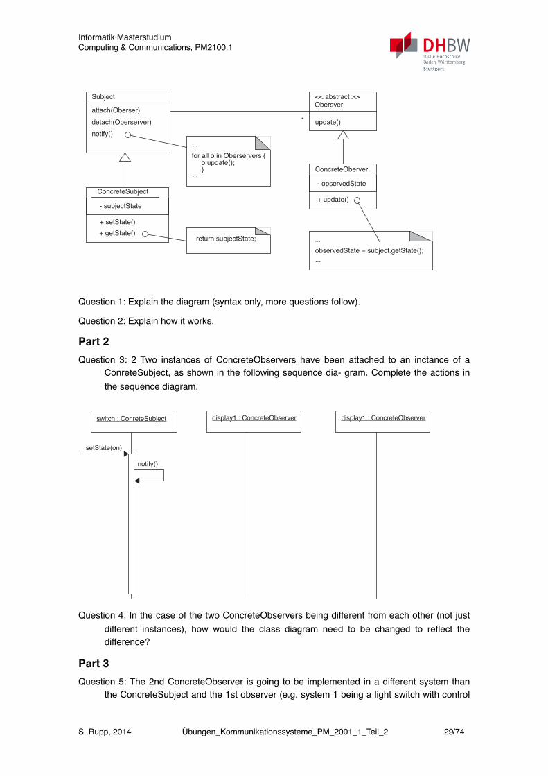
7.2 Part Two (Complete Book) 265
.
Question 1: Explain the diagram (syntax only, more questions follow).
Question 2: Explain how it works.
Part 2
Question 3: 2 Two instances of ConcreteObservers have been attached to aninctance of a ConreteSubject, as shown in the following sequence dia-gram. Complete the actions in the sequence diagram.
...
...
observedState = subject.getState();
Subject << abstract >>
update()
attach(Oberser)
ConcreteOberver
+ update()
detach(Oberserver)
notify()
Obersver
- opservedStateConcreteSubject
+ setState()
- subjectState
+ getState()
...
for all o in Oberservers {
...
o.update(); }
return subjectState;
*
Question 1: Explain the diagram (syntax only, more questions follow).
Question 2: Explain how it works.
Part 2Question 3: 2 Two instances of ConcreteObservers have been attached to an inctance of a
ConreteSubject, as shown in the following sequence dia- gram. Complete the actions in the sequence diagram.
266 7 Exercises
Question 4: In the case of the two ConcreteObservers being different fromeach other (not just different instances), how would the class diagramneed to be changed to reflect the difference?
Part 3
Question 5: The 2nd ConcreteObserver is going to be implemented in a dif-ferent system than the ConcreteSubject and the 1st observer (e.g. system1 being a light switch with control LED and system 2 the light). Explainwhich additional context is needed to make both systems interact.
Question 6: In such a network, it is essential to connect the right sensor tothe right actor (i.e. match light switches to the right lights). Also, itshould be possible to add and remove devices easily at any time. Explainthe corresponding issues and possible solutions.
Question 7: Security. Name security issues in such a network and possiblemeasures for protection.
Question 8: Explain how certificates could be used to improve security is-sues.
7.2.20 Fixed Mobile Convergence
A Fixed Network Operator plans to provide a uniform telephone service incooperation with a Mobile Network Operator (so called Fixed-Mobile-Con-vergence): When a mobile subscriber is close to his fixed line at home or atwork, calls to his mobile set are diverted automatically to the fixed line. Theservice is provided with two options: either calls in the home location may bepicked up with a fixced line telephone set (option 1), or calls are picked up
display1 : ConcreteObserver
setState(on)
switch : ConreteSubject
notify()
display1 : ConcreteObserver
Question 4: In the case of the two ConcreteObservers being different from each other (not just different instances), how would the class diagram need to be changed to reflect the difference?
Part 3Question 5: The 2nd ConcreteObserver is going to be implemented in a different system than
the ConcreteSubject and the 1st observer (e.g. system 1 being a light switch with control
Informatik MasterstudiumComputing & Communications, PM2100.1
S. Rupp, 2014 Übungen_Kommunikationssysteme_PM_2001_1_Teil_2 29/74
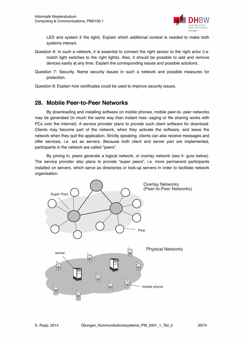
LED and system 2 the light). Explain which additional context is needed to make both systems interact.
Question 6: In such a network, it is essential to connect the right sensor to the right actor (i.e. match light switches to the right lights). Also, it should be possible to add and remove devices easily at any time. Explain the corresponding issues and possible solutions.
Question 7: Security. Name security issues in such a network and possible measures for protection.
Question 8: Explain how certificates could be used to improve security issues.
28. Mobile Peer-to-Peer NetworksBy downloading and installing software on mobile phones, mobile peer-to- peer networks
may be generated (in much the same way than instant mes- saging or file sharing works with PCs over the Internet). A service provider plans to provide such client software for download. Clients may become part of the network, when they activate the software, and leave the network when they quit the application. Strictly speaking, clients can also receive messages and offer services, i.e. act as servers. Because both client and server part are implemented, participants in the network are called “peers”.
By joining in, peers generate a logical network, or overlay network (see fi- gure below). The service provider also plans to provide “super peers”, i.e. more permanent participants installed on servers, which serve as directories or look-up servers in order to facilitate network organisation.
270 7 Exercises
Part 3
In the service described in Part 2, authentication of devices is based on Blue-tooth link keys (K_ab), which are 128 bit numbers. Given a hugh amount ofbluetooth devices, a device might accidently authenticate to another device byhaving a matching link key.
Question 7: If link keys are randomly distributed, what is the probablility,that among 10.000 Mio. of devices, all link keys are different?
Question 8: Given one specific device, what is the probability that no otherdevice (among the 10.000 Mio. devices) has the same link key?
7.2.21 Mobile Peer-to-Peer Networks
By downloading and installing software on mobile phones, mobile peer-to-peer networks may be generated (in much the same way than instant mes-saging or file sharing works with PCs over the Internet). A service providerplans to provide such client software for download. Clients may become partof the network, when they activate the software, and leave the network whenthey quit the application. Strictly speaking, clients can also receive messagesand offer services, i.e. act as servers. Because both client and server part areimplemented, participants in the network are called “peers”.
By joining in, peers generate a logical network, or overlay network (see fi-gure below). The service provider also plans to provide “super peers”, i.e. mo-re permanent participants installed on servers, which serve as directories orlook-up servers in order to facilitate network organisation.
Overlay Networks
Physical Networks
(Peer-to-Peer Networks)
mobile phone
server
Peer
Super Peer
Informatik MasterstudiumComputing & Communications, PM2100.1
S. Rupp, 2014 Übungen_Kommunikationssysteme_PM_2001_1_Teil_2 30/74
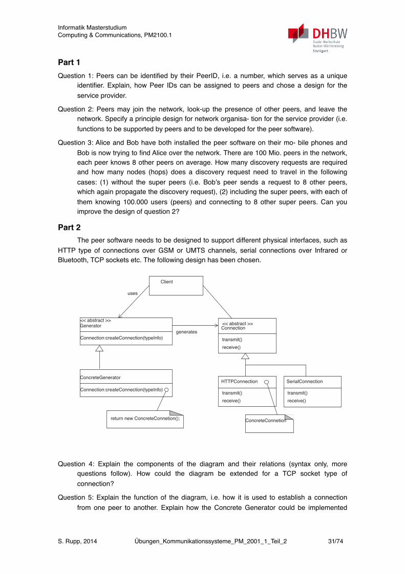
Part 1Question 1: Peers can be identified by their PeerID, i.e. a number, which serves as a unique
identifier. Explain, how Peer IDs can be assigned to peers and chose a design for the service provider.
Question 2: Peers may join the network, look-up the presence of other peers, and leave the network. Specify a principle design for network organisa- tion for the service provider (i.e. functions to be supported by peers and to be developed for the peer software).
Question 3: Alice and Bob have both installed the peer software on their mo- bile phones and Bob is now trying to find Alice over the network. There are 100 Mio. peers in the network, each peer knows 8 other peers on average. How many discovery requests are required and how many nodes (hops) does a discovery request need to travel in the following cases: (1) without the super peers (i.e. Bob’s peer sends a request to 8 other peers, which again propagate the discovery request), (2) including the super peers, with each of them knowing 100.000 users (peers) and connecting to 8 other super peers. Can you improve the design of question 2?
Part 2The peer software needs to be designed to support different physical interfaces, such as
HTTP type of connections over GSM or UMTS channels, serial connections over Infrared or Bluetooth, TCP sockets etc. The following design has been chosen.
7.2 Part Two (Complete Book) 271
Part 1
Question 1: Peers can be identified by their PeerID, i.e. a number, which ser-ves as a unique identifier. Explain, how Peer IDs can be assigned to peersand chose a design for the service provider.
Question 2: Peers may join the network, look-up the presence of other peers,and leave the network. Specify a principle design for network organisa-tion for the service provider (i.e. functions to be supported by peers andto be developed for the peer software).
Question 3: Alice and Bob have both installed the peer software on their mo-bile phones and Bob is now trying to find Alice over the network. Thereare 100 Mio. peers in the network, each peer knows 8 other peers on ave-rage. How many discovery requests are required and how many nodes(hops) does a discovery request need to travel in the following cases: (1)without the super peers (i.e. Bob’s peer sends a request to 8 other peers,which again propagate the discovery request), (2) including the superpeers, with each of them knowing 100.000 users (peers) and connectingto 8 other super peers. Can you improve the design of question 2?
Part 2
The peer software needs to be designed to support different physical inter-faces, such as HTTP type of connections over GSM or UMTS channels, serialconnections over Infrared or Bluetooth, TCP sockets etc. The following designhas been chosen.
return new ConcreteConnetion();
Connection
<< abstract >>
Connection:createConnection(typeInfo) transmit()
Generator << abstract >>
Connection:createConnection(typeInfo)
ConcreteGeneratorHTTPConnection
transmit()
SerialConnection
transmit()
Client
ConcreteConnetion
uses
generates
receive()
receive() receive()
Question 4: Explain the components of the diagram and their relations (syntax only, more questions follow). How could the diagram be extended for a TCP socket type of connection?
Question 5: Explain the function of the diagram, i.e. how it is used to establish a connection from one peer to another. Explain how the Concrete Generator could be implemented
Informatik MasterstudiumComputing & Communications, PM2100.1
S. Rupp, 2014 Übungen_Kommunikationssysteme_PM_2001_1_Teil_2 31/74
and what the typeInfo needs to contain in order to connect to another peer over the network.
Question 6: Explain the sequence of events when connecting from one peer to another over a HTTP connection in a sequence diagram.
Part 3Alice installs a new service on her mobile phone, which provides access to her photo
library over the peer-to-peer network. Bob has been able to discover the phone of Alice and is able connect to Alice.
Question 7: How can Bob discover the new service and find out what it is? Explain which information needs to be specified for service discovery and give some guidelines for implementation.
Question 8: Following discovery, what is needed to access and use the service? Explain which information needs to be specified on the phone of Alice and how the service can be invoked by Bob.
29. CORBA and RMIThe figure shows the process of generating a server application and a matching client
application by use of CORBA, as well as the resulting architecture.
Informatik MasterstudiumComputing & Communications, PM2100.1
S. Rupp, 2014 Übungen_Kommunikationssysteme_PM_2001_1_Teil_2 32/74

!
228 7 Exercises
The figure shows the process of generating a server application and a mat-ching client application by use of CORBA, as well as the resulting architectu-re.
Question 11.1: Explain the process and the role of the resulting componentson the system.
Question 11.2: When using the Java Remote Method Invokation (RMI), theprocedure is similar as with CORBA. However, there are some charac-teristic differences. Compare both technologies.
7.1.12 Clients and Servers
Explain the difference between a client and a server.
7.1.13 Threads and Processes
Threads are flows of control within the address space of a process.
Server
MiddlewareJavaSkeleton
Obj.Adapter
ORB Core
Client
ORB Core
C++Stub
ObRf
IIOP
C++Stub
JavaSkeleton
ObjectInterfaceDefinition
IDL to C++Compiler
IDL to JavaCompiler
C++Interface
JavaInterface
C++ClientApplication
JavaServerApplication
C++ Compiler
Java Compiler
written by application developer
Question 1: Explain the process and the role of the resulting components on the system.
Question 2: When using the Java Remote Method Invokation (RMI), the procedure is similar as with CORBA. However, there are some charac- teristic differences. Compare both technologies.
30. CORBA and Web-ServicesWhile using CORBA, a client-stub is compiled from a formal interface definition which is
contained in an IDL-file. Name an equivalent formal description of the interface with Web-Services.
31. Remote Control for Home NetworksDevices at home, such as TV, stereo, lights, door opener, cookers, washing machines
etc. increasingly support interfaces, which allow to monitor their sta- tes and allow to call actions on them. However, most of the device interfaces are proprietary, i.e. they are specified any way their vendor likes. Thus, a universal remote control for a variety of devices needs to be developed in a way that allows to handle a multitude of interfaces and is easily extensible.
Informatik MasterstudiumComputing & Communications, PM2100.1
S. Rupp, 2014 Übungen_Kommunikationssysteme_PM_2001_1_Teil_2 33/74
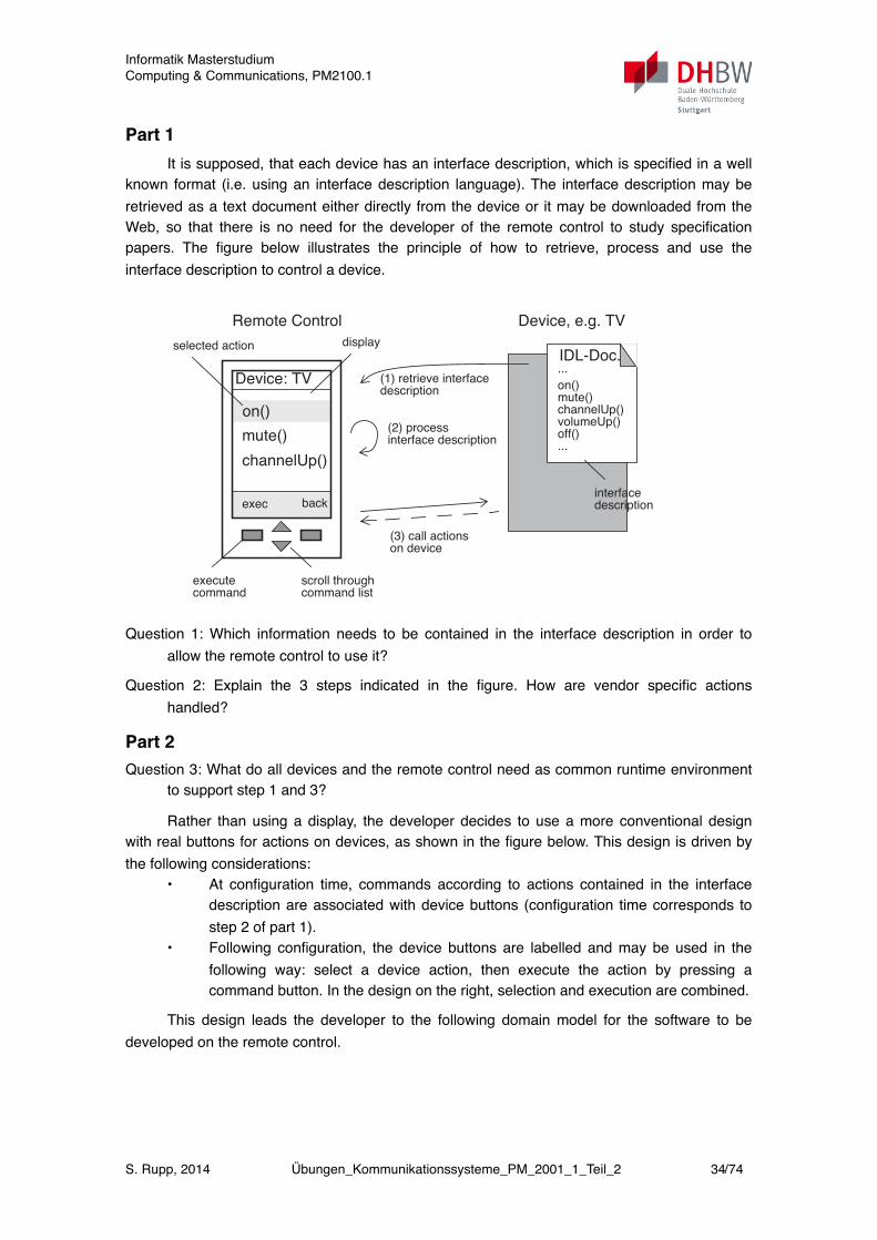
Part 1It is supposed, that each device has an interface description, which is specified in a well
known format (i.e. using an interface description language). The interface description may be retrieved as a text document either directly from the device or it may be downloaded from the Web, so that there is no need for the developer of the remote control to study specification papers. The figure below illustrates the principle of how to retrieve, process and use the interface description to control a device.
!
7.2 Part Two (Complete Book) 277
7.2.23 Remote Control for Home Networks
Devices at home, such as TV, stereo, lights, door opener, cookers, washing
machines etc. increasingly support interfaces, which allow to monitor their sta-
tes and allow to call actions on them. However, most of the device interfaces
are proprietary, i.e. they are specified any way their vendor likes. Thus, a uni-
versal remote control for a variety of devices needs to be developed in a way
that allows to handle a multitude of interfaces and is easily extensible.
Part 1
It is supposed, that each device has an interface description, which is speci-
fied in a well known format (i.e. using an interface description language). The
interface description may be retrieved as a text document either directly from
the device or it may be downloaded from the Web, so that there is no need for
the developer of the remote control to study specification papers. The figure
below illustrates the principle of how to retrieve, process and use the interface
description to control a device.
Question 1: Which information needs to be contained in the interface de-
scription in order to allow the remote control to use it?
Question 2: Explain the 3 steps indicated in the figure. How are vendor spe-
cific actions handled?
Question 3: What do all devices and the remote control need as common
runtime environment to support step 1 and 3?
Part 2
mute()
channelUp()
Device: TV
on()
selected action
scroll throughexecutecommand listcommand
exec back
Remote Control Device, e.g. TV
on()mute()channelUp()volumeUp()off()...
...IDL-Doc.
(1) retrieve interface
(2) process
(3) call actions
description
interface description
on device
interfacedescription
display
Question 1: Which information needs to be contained in the interface description in order to allow the remote control to use it?
Question 2: Explain the 3 steps indicated in the figure. How are vendor specific actions handled?
Part 2Question 3: What do all devices and the remote control need as common runtime environment
to support step 1 and 3?
Rather than using a display, the developer decides to use a more conventional design with real buttons for actions on devices, as shown in the figure below. This design is driven by the following considerations:
• At configuration time, commands according to actions contained in the interface description are associated with device buttons (configuration time corresponds to step 2 of part 1).
• Following configuration, the device buttons are labelled and may be used in the following way: select a device action, then execute the action by pressing a command button. In the design on the right, selection and execution are combined.
This design leads the developer to the following domain model for the software to be developed on the remote control.
Informatik MasterstudiumComputing & Communications, PM2100.1
S. Rupp, 2014 Übungen_Kommunikationssysteme_PM_2001_1_Teil_2 34/74
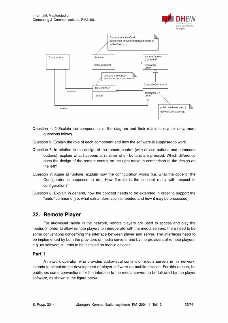
278 7 Exercises
Rather than using a display, the developer decides to use a more conventio-nal design with real buttons for actions on devices, as shown in the figure be-low.
This design is driven by the following considerations:(1) At configuration time, commands according to actions contained in the
interface description are associated with device buttons (configuration timecorresponds to step 2 of part 1).
(2) Following configuration, the device buttons are labelled and may be usedin the following way: select a device action, then execute the action by pres-sing a command button. In the design on the right, selection and execution arecombined.
This design leads the developer to the following domain model for the soft-
ware to be developed on the remote control.
execute
Remote Control
undo
lighton
TVon
dooropen
StereosetDVD
StereosetTV
lightoff
TVmute
door lock
StereosetRadio
commandbuttons
devicebuttons
Remote Control
undo
lighton
TVon
dooropen
StereosetDVD
StereosetTV
lightoff
TVmute
door lock
StereosetRadio
devicebuttonsexecutecommands
public void execute() {
}
deviceCtrler.action();
Activator << interface>>
execute()
ConcreteCommand
setCommand()
Command
undo()
execute()undo()
DeviceCtrler
action()
Configurator
creates
creates
public void setCommand(Command c) {
}
activeCmd = c;
Command activeCmd;
contains the vendorspecific actions on devices
Question 4: 2 Explain the components of the diagram and their relations (syntax only, more questions follow).
Question 5: Explain the role of each component and how the software is supposed to work.
Question 6: In relation to the design of the remote control (with device buttons and command buttons), explain what happens at runtime when buttons are pressed. Which difference does the design of the remote control on the right make in comparison to the design on the left?
Question 7: Again at runtime, explain how the configuration works (i.e. what the code of the Configurator is supposed to do). How flexible is the concept really with respect to configuration?
Question 8: Explain in general, how the concept needs to be extended in order to support the “undo” command (i.e. what extra information is needed and how it may be processed).
32. Remote PlayerFor audivisual media in the network, remote players are used to access and play the
media. In order to allow remote players to interoperate with the media servers, there need to be some conventions concerning the interface between player and server. The interfaces need to be implemented by both the providers of media servers, and by the providers of remote players, e.g. as software cli- ents to be installed on mobile devices.
Part 1A network operator, who provides audiovisual content on media servers in his network,
intends to stimulate the development of player software on mobile devices. For this reason, he publishes some conventions for the interface to the media servers to be followed by the player software, as shown in the figure below.
Informatik MasterstudiumComputing & Communications, PM2100.1
S. Rupp, 2014 Übungen_Kommunikationssysteme_PM_2001_1_Teil_2 35/74
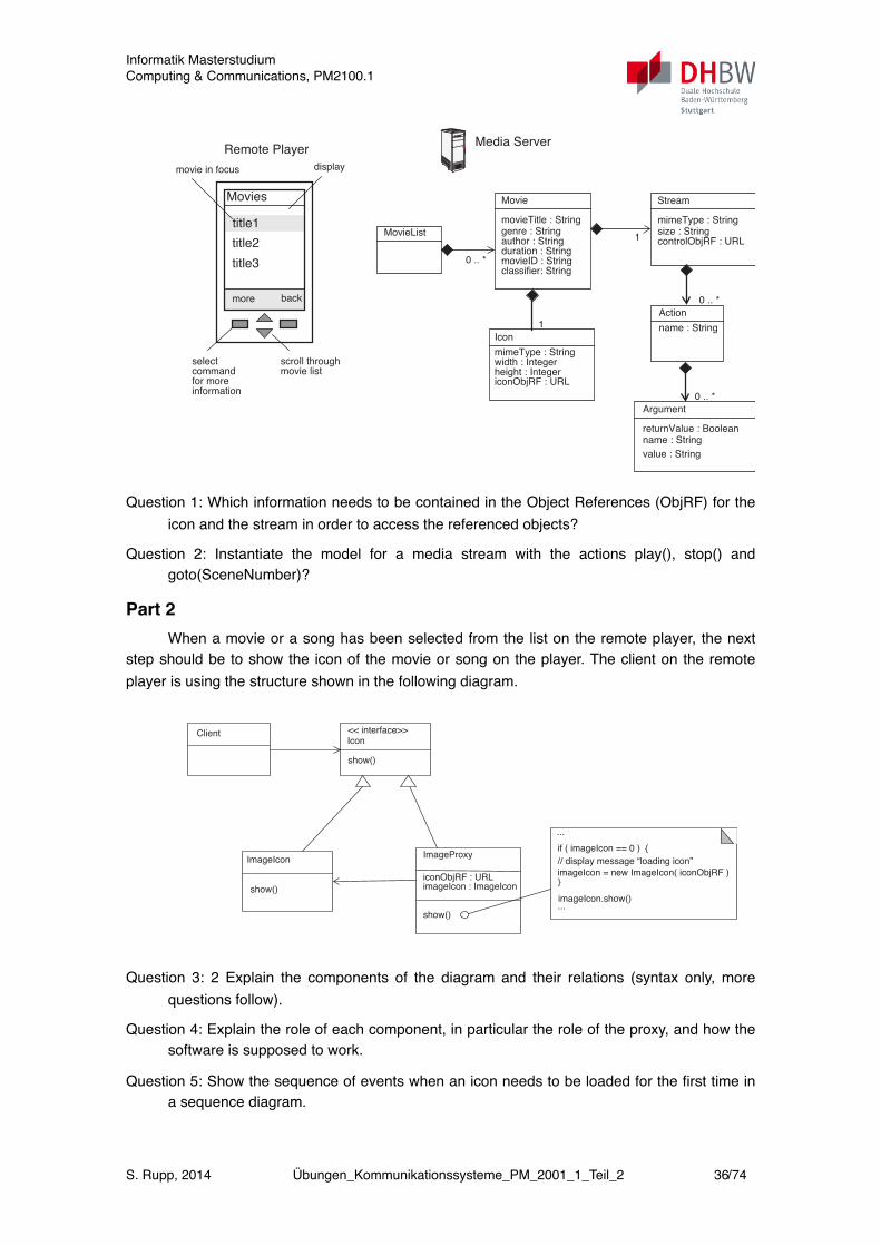
282 7 Exercises
the media servers to be followed by the player software, as shown in the figure
below.
Question 1: Which information needs to be contained in the Object Refe-
rences (ObjRF) for the icon and the stream in order to access the refe-
renced objects?
Question 2: Instantiate the model for a media stream with the actions play(),
stop() and goto(SceneNumber)?
Part 2
When a movie or a song has been selected from the list on the remote player,the next step should be to show the icon of the movie or song on the player.The client on the remote player is using the structure shown in the followingdiagram.
title2
title3
Movies
title1
movie in focus
scroll throughselectmovie listcommand
more back
Remote Player
display
Media Server
Movie
movieTitle : Stringgenre : String
Action
name : String
1author : Stringduration : StringmovieID : String
Stream
mimeType : Stringsize : StringcontrolObjRF : URL
Argument
returnValue : Booleanname : String
value : String
Icon
mimeType : Stringwidth : Integerheight : IntegericonObjRF : URL
1
0 .. *
0 .. *
MovieList
0 .. *
for moreinformation
classifier: String
Question 1: Which information needs to be contained in the Object References (ObjRF) for the icon and the stream in order to access the referenced objects?
Question 2: Instantiate the model for a media stream with the actions play(), stop() and goto(SceneNumber)?
Part 2When a movie or a song has been selected from the list on the remote player, the next
step should be to show the icon of the movie or song on the player. The client on the remote player is using the structure shown in the following diagram.
7.2 Part Two (Complete Book) 283
.
Question 3: 2 Explain the components of the diagram and their relations
(syntax only, more questions follow).
Question 4: Explain the role of each component, in particular the role of the
proxy, and how the software is supposed to work.
Question 5: Show the sequence of events when an icon needs to be loaded
for the first time in a sequence diagram.
Question 6: One drawback of the procedure is, that if the proxy needs to load
the image icon, the procedure will not return until the icon has been loa-
ded, which freezes the client interface. Describe a way to improve this
situation.
Part 3
Not every content on the media server is intended for everybody. The freemovies and songs are available for everone, but there is also material, whichis not free of charge and other material only intended for adults. So the mediaserver will need some access control.
Question 7: What credentials could be used to authenticate users who want
to access classified content? Describe a suitable procedure for authenti-
cation.
Question 8: How could the class diagram be extended to support access for
authenticated users? How would the new procedure work? Hint: There
can be more than one proxy.
if ( imageIcon == 0 ) {
...
<< interface>>
show()
ImageProxy
Icon
show()
Client
ImageIcon
show()
imageIcon = new ImageIcon( iconObjRF )}
imageIcon.show()...
iconObjRF : URLimageIcon : ImageIcon
// display message “loading icon”
Question 3: 2 Explain the components of the diagram and their relations (syntax only, more questions follow).
Question 4: Explain the role of each component, in particular the role of the proxy, and how the software is supposed to work.
Question 5: Show the sequence of events when an icon needs to be loaded for the first time in a sequence diagram.
Informatik MasterstudiumComputing & Communications, PM2100.1
S. Rupp, 2014 Übungen_Kommunikationssysteme_PM_2001_1_Teil_2 36/74
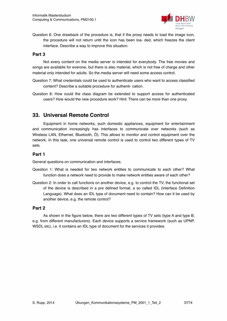
Question 6: One drawback of the procedure is, that if the proxy needs to load the image icon, the procedure will not return until the icon has been loa- ded, which freezes the client interface. Describe a way to improve this situation.
Part 3Not every content on the media server is intended for everybody. The free movies and
songs are available for everone, but there is also material, which is not free of charge and other material only intended for adults. So the media server will need some access control.
Question 7: What credentials could be used to authenticate users who want to access classified content? Describe a suitable procedure for authenti- cation.
Question 8: How could the class diagram be extended to support access for authenticated users? How would the new procedure work? Hint: There can be more than one proxy.
33. Universal Remote ControlEquipment in home networks, such domestic appliances, equipment for entertainment
and communication increasingly has interfaces to communicate over networks (such as Wireless LAN, Ethernet, Bluetooth, Ö). This allows to monitor and control equipment over the network. In this task, one universal remote control is used to control two different types of TV sets.
Part 1General questions on communication and interfaces.
Question 1: What is needed for two network entities to communicate to each other? What function does a network need to provide to make network entities aware of each other?
Question 2: In order to call functions on another device, e.g. to control the TV, the functional set of the device is described in a pre defined format, a so called IDL (Interface Definition Language). What does an IDL type of document need to contain? How can it be used by another device, e.g. the remote control?
Part 2As shown in the figure below, there are two different types of TV sets (type A and type B,
e.g. from different manufacturers). Each device supports a service framework (such as UPNP, WSDL etc), i.e. it contains an IDL type of document for the services it provides.
Informatik MasterstudiumComputing & Communications, PM2100.1
S. Rupp, 2014 Übungen_Kommunikationssysteme_PM_2001_1_Teil_2 37/74
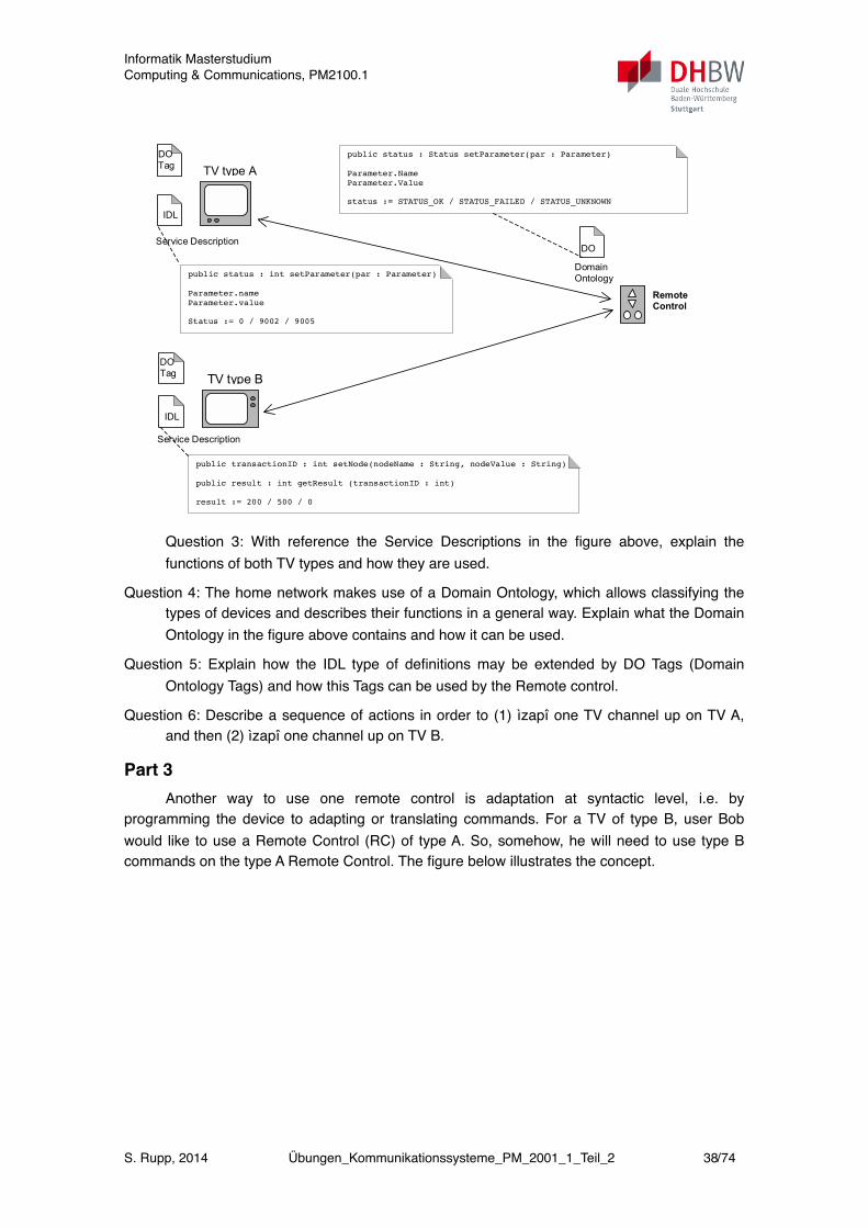
Telecommunication Software Engineering ñ Examination Oct 5, 2007
S. Rupp 3
Part 2 As shown in the figure below, there are two different types of TV sets (type A and type B, e.g. from different manufacturers). Each device supports a service framework (such as UPNP, WSDL etc), i.e. it contains an IDL type of document for the services it provides.
Question 3: With reference the Service Descriptions in the figure above, explain the functions of both TV types and how they are used. Question 4: The home network makes use of a Domain Ontology, which allows classifying the types of devices and describes their functions in a general way. Explain what the Domain Ontology in the figure above contains and how it can be used. Question 5: Explain how the IDL type of definitions may be extended by DO Tags (Domain Ontology Tags) and how this Tags can be used by the Remote control. Question 6: Describe a sequence of actions in order to (1) ìzapî one TV channel up on TV A, and then (2) ìzapî one channel up on TV B.
TV type A
TV type B
RemoteControl
IDL
IDL
DO Tag
DO Tag
DO
Domain Ontology public status : int setParameter(par : Parameter)
Parameter.name Parameter.value Status := 0 / 9002 / 9005
public status : Status setParameter(par : Parameter) Parameter.Name Parameter.Value status := STATUS_OK / STATUS_FAILED / STATUS_UNKNOWN
public transactionID : int setNode(nodeName : String, nodeValue : String) public result : int getResult (transactionID : int) result := 200 / 500 / 0
Service Description
Service Description
Question 3: With reference the Service Descriptions in the figure above, explain the functions of both TV types and how they are used.
Question 4: The home network makes use of a Domain Ontology, which allows classifying the types of devices and describes their functions in a general way. Explain what the Domain Ontology in the figure above contains and how it can be used.
Question 5: Explain how the IDL type of definitions may be extended by DO Tags (Domain Ontology Tags) and how this Tags can be used by the Remote control.
Question 6: Describe a sequence of actions in order to (1) ìzapî one TV channel up on TV A, and then (2) ìzapî one channel up on TV B.
Part 3Another way to use one remote control is adaptation at syntactic level, i.e. by
programming the device to adapting or translating commands. For a TV of type B, user Bob would like to use a Remote Control (RC) of type A. So, somehow, he will need to use type B commands on the type A Remote Control. The figure below illustrates the concept.
Informatik MasterstudiumComputing & Communications, PM2100.1
S. Rupp, 2014 Übungen_Kommunikationssysteme_PM_2001_1_Teil_2 38/74
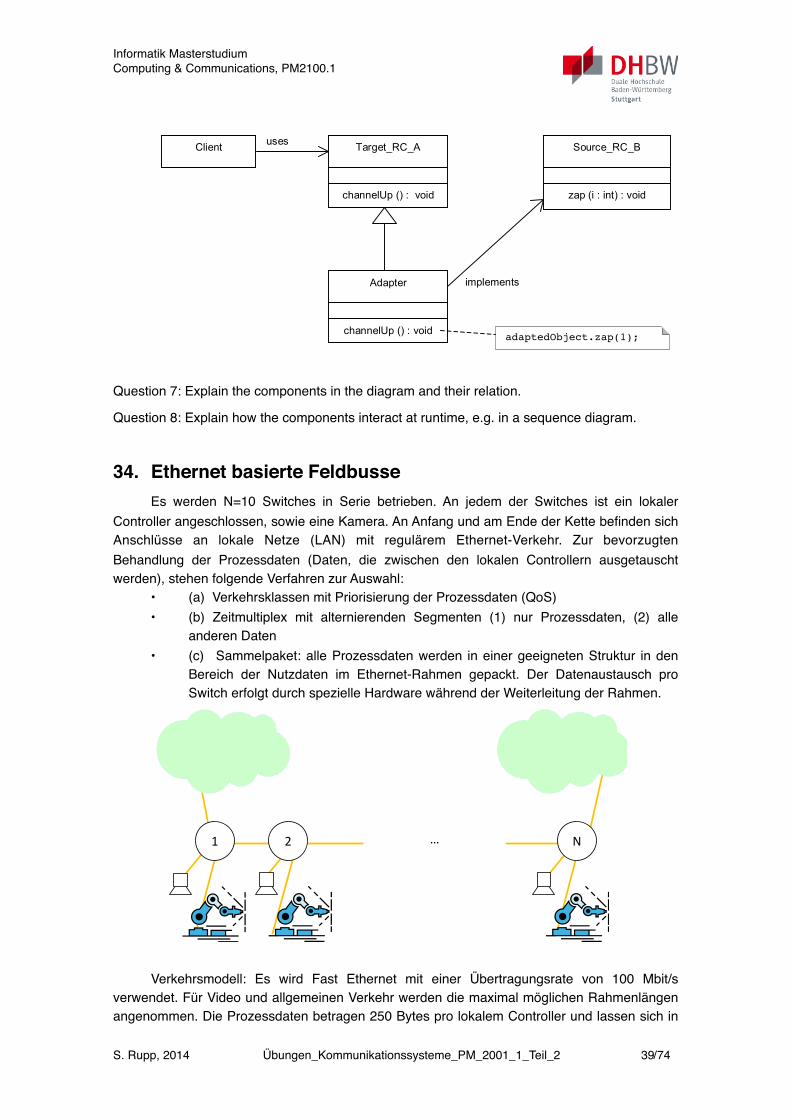
Telecommunication Software Engineering ñ Examination Oct 5, 2007
S. Rupp 4
Part 3 Another way to use one remote control is adaptation at syntactic level, i.e. by programming the device to adapting or translating commands. For a TV of type B, user Bob would like to use a Remote Control (RC) of type A. So, somehow, he will need to use type B commands on the type A Remote Control. The figure below illustrates the concept.
Question 7: Explain the components in the diagram and their relation. Question 8: Explain how the components interact at runtime, e.g. in a sequence diagram.
uses
adaptedObject.zap(1);
implements
Client Target_RC_A
channelUp () : void
Source_RC_B
zap (i : int) : void
Adapter
channelUp () : void
Question 7: Explain the components in the diagram and their relation.
Question 8: Explain how the components interact at runtime, e.g. in a sequence diagram.
34. Ethernet basierte FeldbusseEs werden N=10 Switches in Serie betrieben. An jedem der Switches ist ein lokaler
Controller angeschlossen, sowie eine Kamera. An Anfang und am Ende der Kette befinden sich Anschlüsse an lokale Netze (LAN) mit regulärem Ethernet-Verkehr. Zur bevorzugten Behandlung der Prozessdaten (Daten, die zwischen den lokalen Controllern ausgetauscht werden), stehen folgende Verfahren zur Auswahl:
• (a) Verkehrsklassen mit Priorisierung der Prozessdaten (QoS) • (b) Zeitmultiplex mit alternierenden Segmenten (1) nur Prozessdaten, (2) alle
anderen Daten • (c) Sammelpaket: alle Prozessdaten werden in einer geeigneten Struktur in den
Bereich der Nutzdaten im Ethernet-Rahmen gepackt. Der Datenaustausch pro Switch erfolgt durch spezielle Hardware während der Weiterleitung der Rahmen.
Ethernet basierte FeldbusseEs werden N=10 Switches in Serie betrieben. An jedem der Switches ist ein lokaler
Controller angeschlossen, sowie eine Kamera. An Anfang und am Ende der Kette befinden sich Anschlüsse an lokale Netze (LAN) mit regulärem Ethernet-Verkehr. Zur bevorzugten Behandlung der Prozessdaten (Daten, die zwischen den lokalen Controllern ausgetauscht werden), stehen folgende Verfahren zur Auswahl:
(a) Verkehrsklassen mit Priorisierung der Prozessdaten (QoS)
(b) Zeitmultiplex mit alternierenden Segmenten (1) nur Prozessdaten, (2) alle anderen Daten
(c) Sammelpaket: alle Prozessdaten werden in einer geeigneten Struktur in den Bereich der Nutzdaten im Ethernet-Rahmen gepackt. Der Datenaustausch pro Switch erfolgt durch spezielle Hardware während der Weiterleitung der Rahmen.
… 2 1 N
Verkehrsmodell: Es wird Fast Ethernet mit einer Übertragungsrate von 100 Mbit/s verwendet. Für Video und allgemeinen Verkehr werden die maximal möglichen Rahmenlängen angenommen. Die Prozessdaten betragen 250 Bytes pro lokalem Controller und lassen sich in Rahmen der Länge 256 Bytes übertragen. Für die Weiterleitung der Rahmen wird pro Switch eine Verarbeitungszeit (Latenz) von 0,01 ms angenommen.
Frage 1: Berechnen Sie für das Verfahren (a) überschlägig die Laufzeitschwankungen am Ende der Kette für den unter den folgenden Annahmen: maximale Paketlänge (1) 9000 Bytes, (2) 1500 Bytes, (3) 512 Bytes.
Frage 2: Berechnen Sie zum Vergleich überschlägig Verfahren (b).
Frage 3: Berechnen Sie überschlägig zum Vergleich Verfahren (c).
Bemerkung: Excel-Formular zur Kalkulation
Communications Engineering, 6th Term, Exercises on Networks
S. Rupp, 2012 Exercises_Networks_V01 1
Verkehrsmodell: Es wird Fast Ethernet mit einer Übertragungsrate von 100 Mbit/s verwendet. Für Video und allgemeinen Verkehr werden die maximal möglichen Rahmenlängen angenommen. Die Prozessdaten betragen 250 Bytes pro lokalem Controller und lassen sich in
Informatik MasterstudiumComputing & Communications, PM2100.1
S. Rupp, 2014 Übungen_Kommunikationssysteme_PM_2001_1_Teil_2 39/74
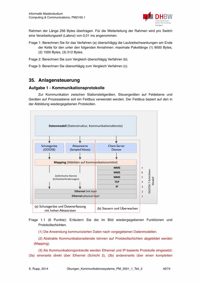
Rahmen der Länge 256 Bytes übertragen. Für die Weiterleitung der Rahmen wird pro Switch eine Verarbeitungszeit (Latenz) von 0,01 ms angenommen.
Frage 1: Berechnen Sie für das Verfahren (a) überschlägig die Laufzeitschwankungen am Ende der Kette für den unter den folgenden Annahmen: maximale Paketlänge (1) 9000 Bytes, (2) 1500 Bytes, (3) 512 Bytes.
Frage 2: Berechnen Sie zum Vergleich überschlägig Verfahren (b).
Frage 3: Berechnen Sie überschlägig zum Vergleich Verfahren (c).
35. AnlagensteuerungAufgabe 1 - Kommunikationsprotokolle
Zur Kommunikation zwischen Stationsleitgeräten, Steuergeräten auf Feldebene und Geräten auf Prozessebene soll ein Feldbus verwendet werden. Der Feldbus basiert auf den in der Abbildung wiedergegebenen Protokollen.
Page 21 of y
Date: 26.03.2012 Tobias Gruber, 2012
3 Systemkommunikation
Datenmodell (Datenstruktur, Kommunikationsdienste)
GOOSEAbtastwerte (Samped
Values – SV)Client-Server-Dienste
Mapping (Abbilden auf Kommunikationsmittel)
Ethernet physical layer
Ethernet link layer
IP
TCP
MMS
MMS
MMS
ISO
/OSI
7-S
chic
hten
-M
odel
l
1
2
3
4
5
6
7
Zeitkritische Dienste (Echtzeitanforderungen)
(a) Schutzgeräte und Datenerfassung mit hohen Abtastraten
(b) Steuern und Überwachen
Abtastwerte (Sampled Values)
Schutzgeräte (GOOSE)
Client-Server Dienste
Frage 1.1 (6 Punkte): Erläutern Sie die im Bild wiedergegebenen Funktionen und Protokollschichten.
(1) Die Anwendung kommunizierten Daten nach vorgegebenen Datenmodellen.
(2) Abstrakte Kommunikationsdienste können auf Protokollschichten abgebildet werden (Mapping).
(3) Als Kommunikationsprotokolle werden Ethernet und IP-basierte Protokolle eingesetzt: (3a) einerseits direkt über Ethernet (Schicht 2), (3b) andererseits über einen kompletten
Informatik MasterstudiumComputing & Communications, PM2100.1
S. Rupp, 2014 Übungen_Kommunikationssysteme_PM_2001_1_Teil_2 40/74
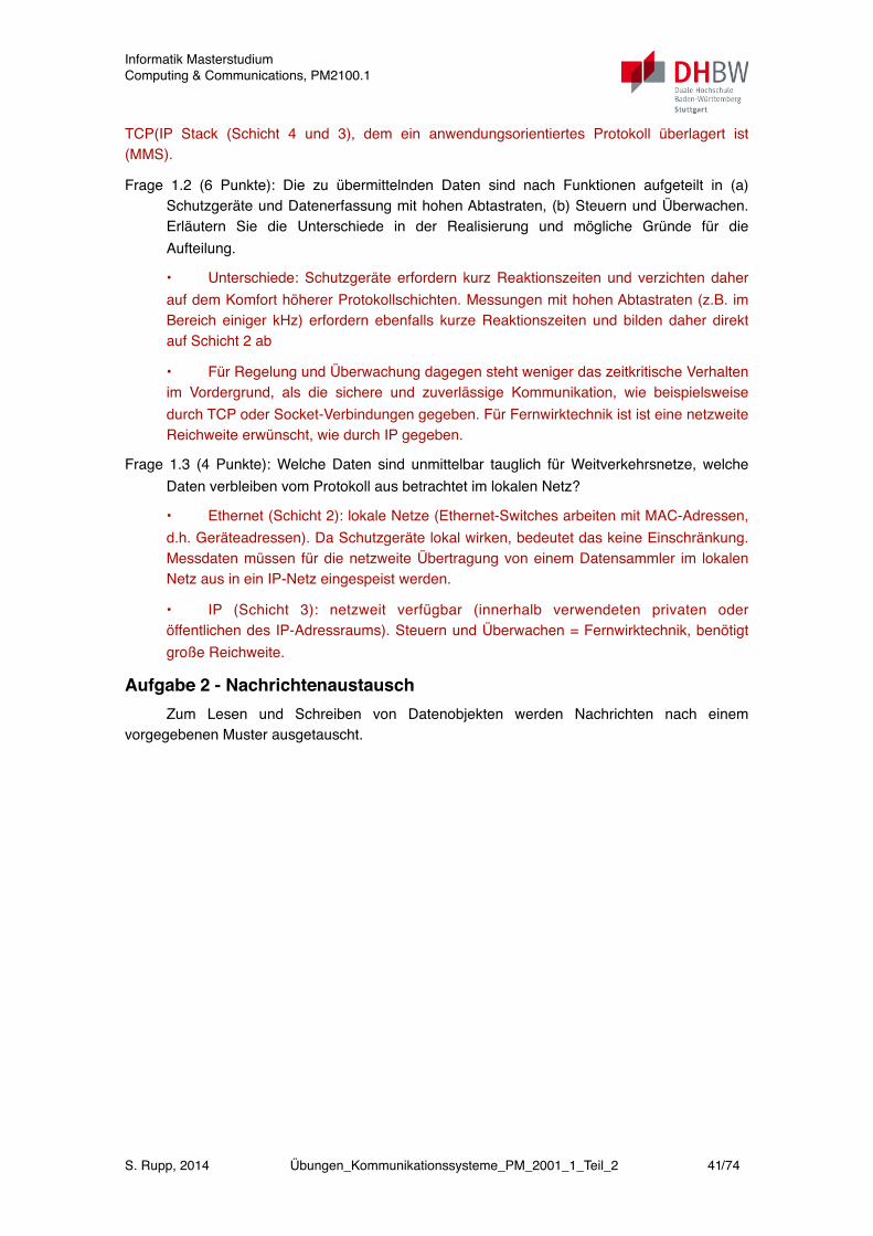
TCP(IP Stack (Schicht 4 und 3), dem ein anwendungsorientiertes Protokoll überlagert ist (MMS).
Frage 1.2 (6 Punkte): Die zu übermittelnden Daten sind nach Funktionen aufgeteilt in (a) Schutzgeräte und Datenerfassung mit hohen Abtastraten, (b) Steuern und Überwachen. Erläutern Sie die Unterschiede in der Realisierung und mögliche Gründe für die Aufteilung.
• Unterschiede: Schutzgeräte erfordern kurz Reaktionszeiten und verzichten daher auf dem Komfort höherer Protokollschichten. Messungen mit hohen Abtastraten (z.B. im Bereich einiger kHz) erfordern ebenfalls kurze Reaktionszeiten und bilden daher direkt auf Schicht 2 ab
• Für Regelung und Überwachung dagegen steht weniger das zeitkritische Verhalten im Vordergrund, als die sichere und zuverlässige Kommunikation, wie beispielsweise durch TCP oder Socket-Verbindungen gegeben. Für Fernwirktechnik ist ist eine netzweite Reichweite erwünscht, wie durch IP gegeben.
Frage 1.3 (4 Punkte): Welche Daten sind unmittelbar tauglich für Weitverkehrsnetze, welche Daten verbleiben vom Protokoll aus betrachtet im lokalen Netz?
• Ethernet (Schicht 2): lokale Netze (Ethernet-Switches arbeiten mit MAC-Adressen, d.h. Geräteadressen). Da Schutzgeräte lokal wirken, bedeutet das keine Einschränkung. Messdaten müssen für die netzweite Übertragung von einem Datensammler im lokalen Netz aus in ein IP-Netz eingespeist werden.
• IP (Schicht 3): netzweit verfügbar (innerhalb verwendeten privaten oder öffentlichen des IP-Adressraums). Steuern und Überwachen = Fernwirktechnik, benötigt große Reichweite.
Aufgabe 2 - NachrichtenaustauschZum Lesen und Schreiben von Datenobjekten werden Nachrichten nach einem
vorgegebenen Muster ausgetauscht.
Informatik MasterstudiumComputing & Communications, PM2100.1
S. Rupp, 2014 Übungen_Kommunikationssysteme_PM_2001_1_Teil_2 41/74
3 Der Standard IEC61850 Seite 23
Abb. 12: Sequenzdiagramm zur Kommunikationsveranschaulichung
aufbauend auf [Sch04], [IEC10-a] und [ABB10]
Zunächst sendet das Stationsleitgerät eine Anfrage, um die Betriebsbereitschaft des Leis-
tungsschalters zu überprüfen. Diese Anfrage geht zuerst an die Schaltersteuerung, die wiede-
rum eine Anfrage an den Leistungsschalter sendet (1. → 2. → 3.). Die Anfrage wird durch
den Leistungsschalter überprüft (check()) und eine Antwort mit dem positiven Betriebszu-
stand erst wieder an die Schaltersteuerung und dann von dieser an das Stationsleitgerät ge-
schickt (3. → 4.).
Anschließend sendet das Stationsleitgerät einen Befehl zum Schalten (OperateRequest(on)) analog der Betriebszustandsabfrage. Nach der Aktivierung des Antriebes schickt der Leis-
tungsschalter eine Nachricht an die Schaltersteuerung zurück, dass der Auftrag ausgeführt
wird. Nach dem erfolgten Schalten des Leistungsschalters, erfolgt eine spontane Meldung des
Wertes mit dem neuen Schaltzustand des Schalters(Report(on)) von 9. → 10.
3.5 Konfigurationssprache
Um ein IEC61850-System normkonform zu modellieren, muss für alle beteiligten Geräte eine
logische Struktur definiert werden.
Zur logischen Struktur gehören u. a. folgende Punkte:
Welche optionalen Daten werden realisiert
sd Exemplarisches Sequenzdiagramm
Stationsleitgerät(LN: IHMI)
Schaltersteuerung(LN: CSWI)
Leistungsschalter(LN: XCBR)
1. SelectRequest (on)
2. SelectRequest (on)
check()
3. SelectResponse +()
4. SelectResponse +()
5. OperateRequest (on)
6. OperateRequest(on)
7. OperateResponse +()
8. OperateResponse +()
9. Report (on)
10. Report (on)
Frage 2.1 (6 Punkte): Rekonstruieren Sie dieses Muster für den Nachrichtenaustausch aus dem Sequenzdiagramm in der Abbildung.
Das Muster für den Nachrichtenaustausch arbeitet in 3 Phasen: (1) Select - Auswahl einer Funktion, (2) Operate - Ausführen einer Instruktion, (3) Report - Bericht über das Ergebnis der Ausführung. In den Phasen (1) und (2) sind Nachrichten für die Anforderungen (Request) und die Quittierung der Anforderung (Response) vorgesehen.
Frage 2.2 (6 Punkte): Welche weitere Vereinbarungen sind erforderlich, damit der Aufruf von Methoden zwischen den Geräten funktionieren kann?
(1) Wenn die Methodenaufrufe über ein Netz erfolgen, ist eine Pfadangabe erforderlich, bestehend aus Protokoll, Netzadresse und Objektname (für die Methode). Eine solche Pfadangabe kann in einem IP-Netz beispielsweise durch eine URL erfolgen, bzw. ein TCP-Socket bzw. UDP-Socket.
(2) Ausserdem sind Vereinbarungen über den Methodenaufruf erforderlich, d.h. die Namen der Methode, der Übergabeparameter, der Rückgabewerte und die jeweils zugehörigen Datentypen.
Aufgabe 3 - EchtzeitverhaltenDie Steuergeräte kommunizieren über eine Kette von Ethernet-Switches. Auf Schicht 2
variieren die Paketlängen zwischen 64 Bytes pro Nachricht und maximal 1500 Bytes pro Nachricht. Es wird Fast Ethernet verwendet (100 Mbit/s). Die Prozessdaten verwenden stets kurze Pakete von 64 Bytes.
Informatik MasterstudiumComputing & Communications, PM2100.1
S. Rupp, 2014 Übungen_Kommunikationssysteme_PM_2001_1_Teil_2 42/74
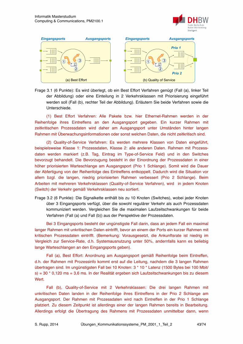
1
2
3
Eingangsports
Prio 1
Ausgangsports
Prio 2
(b) Quality of Service
1
2
3
Eingangsports Ausgangsports
(a) Best Effort
Frage 3.1 (6 Punkte): Es wird überlegt, ob ein Best Effort Verfahren genügt (Fall (a), linker Teil der Abbildung) oder eine Einteilung in 2 Verkehrsklassen mit Priorisierung eingeführt werden soll (Fall (b), rechter Teil der Abbildung). Erläutern Sie beide Verfahren sowie die Unterschiede.
(1) Best Effort Verfahren: Alle Pakete bzw. hier Ethernet-Rahmen werden in der Reihenfolge ihres Eintreffens an den Ausgangsport gegeben. Ein kurzer Rahmen mit zeitkritischen Prozessdaten wird daher am Ausgangsport unter Umständen hinter langen Rahmen mit Überwachungsinformationen oder sonst welchen Daten, die nicht zeitkritisch sind.
(2) Quality-of-Service Verfahren: Es werden mehrere Klassen von Daten eingeführt, beispielsweise Klasse 1: Prozessdaten, Klasse 2: alle anderen Daten. Rahmen mit Prozess-daten werden markiert (z.B. Tag, Eintrag im Type-of-Service Feld) und in den Switches bevorzugt behandelt. Die Bevorzugung besteht in der Einordnung der Prozessdaten in einer höher priorisierten Warteschlange am Ausgangsport (Prio 1 Schlange). Somit wird die Dauer der Abfertigung von der Reihenfolge des Eintreffens entkoppelt. Dadurch wird die Situation vor allem bzgl. die langen, niedrig priorisierten Rahmen verbessert (Prio 2 Schlange). Beim Arbeiten mit mehreren Verkehrsklassen (Quality-of-Service Verfahren), wird in jedem Knoten (Switch) der Verkehr gemäß Verkehrsklassen neu sortiert.
Frage 3.2 (6 Punkte): Die Signalkette enthält bis zu 10 Knoten (Switches), wobei jeder Knoten über 3 Eingangsports verfügt, über die sowohl regulärer Verkehr als auch Prozessdaten kommuniziert werden. Vergleichen Sie die maximalen Laufzeitschwankungen für beide Verfahren (Fall (a) und Fall (b)) aus der Perspektive der Prozessdaten.
Bei 3 Eingangsports besteht der ungünstigste Fall darin, dass an jedem Fall ein maximal langer Rahmen mit unkritischen Daten eintrifft, bevor an einem der Ports ein kurzer Rahmen mit kritischen Prozessdaten eintrifft. (Bemerkung: Vorausgesetzt, die Ankunftsrate ist niedrig im Vergleich zur Service-Rate, d.h. Systemausnutzung unter 50%, andernfalls kann es beliebig lange Warteschlangen an den Eingangsports geben).
Fall (a), Best Effort: Anordnung am Ausgangsport gemäß Reihenfolge beim Eintreffen, d.h. der Rahmen mit Prozessinfo kommt erst auf die Leitung, nachdem die 3 langen Rahmen übertragen sind. Im ungünstigsten Fall bei 10 Knoten: 3 * 10 * Latenz (1500 Bytes bei 100 Mbit/s) = 30 * 0,120 ms = 3,6 ms. In der Realität ergeben sich Laufzeitschwankungen bis zu diesem Wert.
Fall (b), Quality-of-Service mit 2 Verkehrsklassen: Die drei langen Rahmen mit unkritischen Daten landen in der Reihenfolge ihres Eintreffens in der Prio 2 Schlange am Ausgangsport. Der Rahmen mit Prozessdaten wird nach Eintreffen in der Prio 1 Schlange platziert. Zu diesem Zeitpunkt ist allerdings einer der langen Rahmen bereits in Bearbeitung. Allerdings erfolgt die Übertragung des Rahmens mit Prozessdaten unmittelbar dann, wenn
Informatik MasterstudiumComputing & Communications, PM2100.1
S. Rupp, 2014 Übungen_Kommunikationssysteme_PM_2001_1_Teil_2 43/74
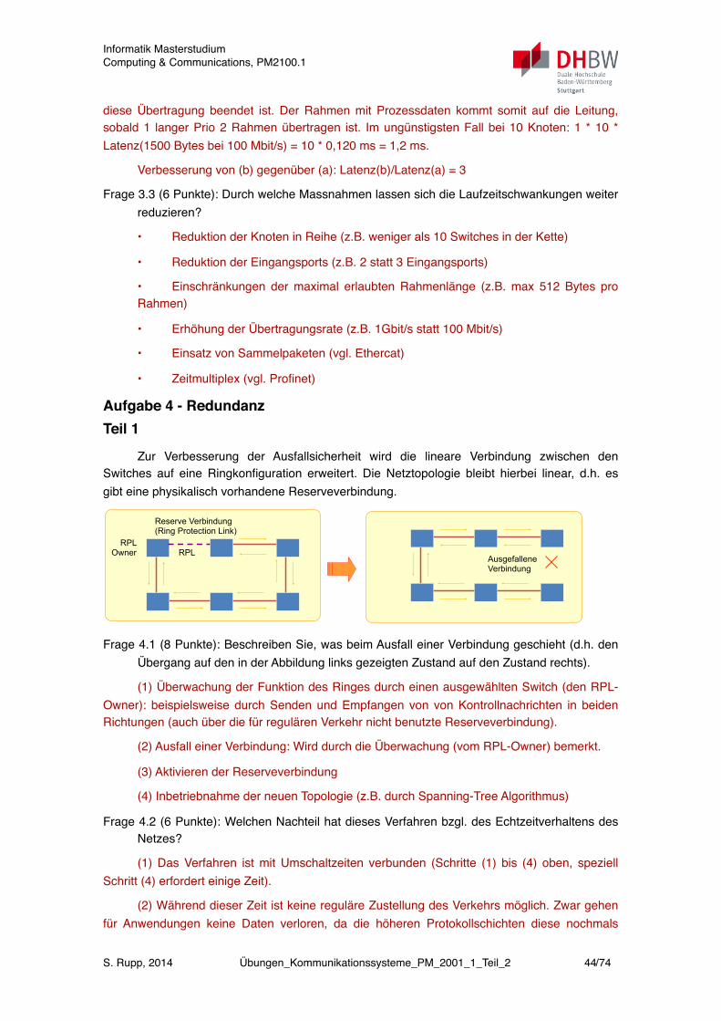
diese Übertragung beendet ist. Der Rahmen mit Prozessdaten kommt somit auf die Leitung, sobald 1 langer Prio 2 Rahmen übertragen ist. Im ungünstigsten Fall bei 10 Knoten: 1 * 10 * Latenz(1500 Bytes bei 100 Mbit/s) = 10 * 0,120 ms = 1,2 ms.
Verbesserung von (b) gegenüber (a): Latenz(b)/Latenz(a) = 3
Frage 3.3 (6 Punkte): Durch welche Massnahmen lassen sich die Laufzeitschwankungen weiter reduzieren?
• Reduktion der Knoten in Reihe (z.B. weniger als 10 Switches in der Kette)
• Reduktion der Eingangsports (z.B. 2 statt 3 Eingangsports)
• Einschränkungen der maximal erlaubten Rahmenlänge (z.B. max 512 Bytes pro Rahmen)
• Erhöhung der Übertragungsrate (z.B. 1Gbit/s statt 100 Mbit/s)
• Einsatz von Sammelpaketen (vgl. Ethercat)
• Zeitmultiplex (vgl. Profinet)
Aufgabe 4 - RedundanzTeil 1
Zur Verbesserung der Ausfallsicherheit wird die lineare Verbindung zwischen den Switches auf eine Ringkonfiguration erweitert. Die Netztopologie bleibt hierbei linear, d.h. es gibt eine physikalisch vorhandene Reserveverbindung.
Ausgefallene Verbindung
RPLRPL
Owner
Reserve Verbindung(Ring Protection Link)
Frage 4.1 (8 Punkte): Beschreiben Sie, was beim Ausfall einer Verbindung geschieht (d.h. den Übergang auf den in der Abbildung links gezeigten Zustand auf den Zustand rechts).
(1) Überwachung der Funktion des Ringes durch einen ausgewählten Switch (den RPL-Owner): beispielsweise durch Senden und Empfangen von von Kontrollnachrichten in beiden Richtungen (auch über die für regulären Verkehr nicht benutzte Reserveverbindung).
(2) Ausfall einer Verbindung: Wird durch die Überwachung (vom RPL-Owner) bemerkt.
(3) Aktivieren der Reserveverbindung
(4) Inbetriebnahme der neuen Topologie (z.B. durch Spanning-Tree Algorithmus)
Frage 4.2 (6 Punkte): Welchen Nachteil hat dieses Verfahren bzgl. des Echtzeitverhaltens des Netzes?
(1) Das Verfahren ist mit Umschaltzeiten verbunden (Schritte (1) bis (4) oben, speziell Schritt (4) erfordert einige Zeit).
(2) Während dieser Zeit ist keine reguläre Zustellung des Verkehrs möglich. Zwar gehen für Anwendungen keine Daten verloren, da die höheren Protokollschichten diese nochmals
Informatik MasterstudiumComputing & Communications, PM2100.1
S. Rupp, 2014 Übungen_Kommunikationssysteme_PM_2001_1_Teil_2 44/74

anfordern, allerdings werden während des Umschaltvorgangs vereinbarte Antwortzeiten nicht eingehalten. Somit ist ein Echtzeitbetrieb (= Einhaltung vereinbarter Antwortzeiten) nur sehr eingeschränkt möglich.
(3) Die Dauer der Umschaltung ist abhängig von der Topologie und Größe des Netzes.
Teil 2
Zur Verbesserung des Echtzeitverhaltens schlägt der Hersteller der Switches die in der folgenden Abbildung gezeigte Konfiguration vor.
Ringredundanz mit zwei gleichzeitig betriebenen VLANs
Red Box: Ringswitch mit Dopplung der Anschlüsse für Geräte mit
einfachem Anschluss (SAN - Single Attached Node)
Node: Geräte (Feldbus-Controller, Schutzgeräte, Messgeräte)
Quelle: ABB
Frage 4.3 (8 Punkte): Interpretieren Sie den Vorschlag und beschreiben Sie das Verhalten im Fehlerfall. Erläutern Sie die Vorteile und Einschränkungen gegenüber dem Verfahren aus Teil 1.
(1) Interpretation: Im Unterschied zu Verfahren aus Teil 1 werden zwei unabhängige Teilnetze in unterschiedlichen Richtungen betrieben. Die Teilnetze sind im Beispiel als VLAN realisiert. Die Redundanz wird im Endgerät erzeugt: Jede Nachricht (jeder Ethernet-Rahmen) wird dupliziert (A-Frame und B-Frame) und in die Teilnetze gegeben. Jedes Endgerät empfängt im Normalfall beide Rahmen und kann einen verwerfen.
(2) Verhalten im Fehlerfall: Bei Ausfall einer Verbindung wird jeder Knoten noch über den alternativen Pfad erreicht, dann allerdings ohne weitere Redundanz. Wie der Fehler behoben wird, ist nicht näher beschrieben (Umkonfiguration wie bei dem Verfahren in Teil 1, Intervention des Betriebspersonals etc.).
(3) Vorteile: keine Umschaltzeiten im Fehlerfall, unterbrechungsfreier Betrieb.
(4) Einschränkungen: komplexere Konfiguration, Duplizieren von Rahmen ist nicht Bestandteil der Ethernet-Standards und erfordert spezielle Maßnahmen (z.B. Redundanz-Boxen), es sind weitere Vereinbarungen erforderlich für die Rückkehr aus dem Fehlerfall in den redundanten Betrieb.
Teil 3Die Anbindung an die übergeordnete Leitebene hat noch höhere Anforderungen bzgl. der
Verfügbarkeit. Daher wird hierfür eine Ausführung als echter Doppelring vorgeschlagen, wie in der folgenden Abbildung gezeigt.
Informatik MasterstudiumComputing & Communications, PM2100.1
S. Rupp, 2014 Übungen_Kommunikationssysteme_PM_2001_1_Teil_2 45/74
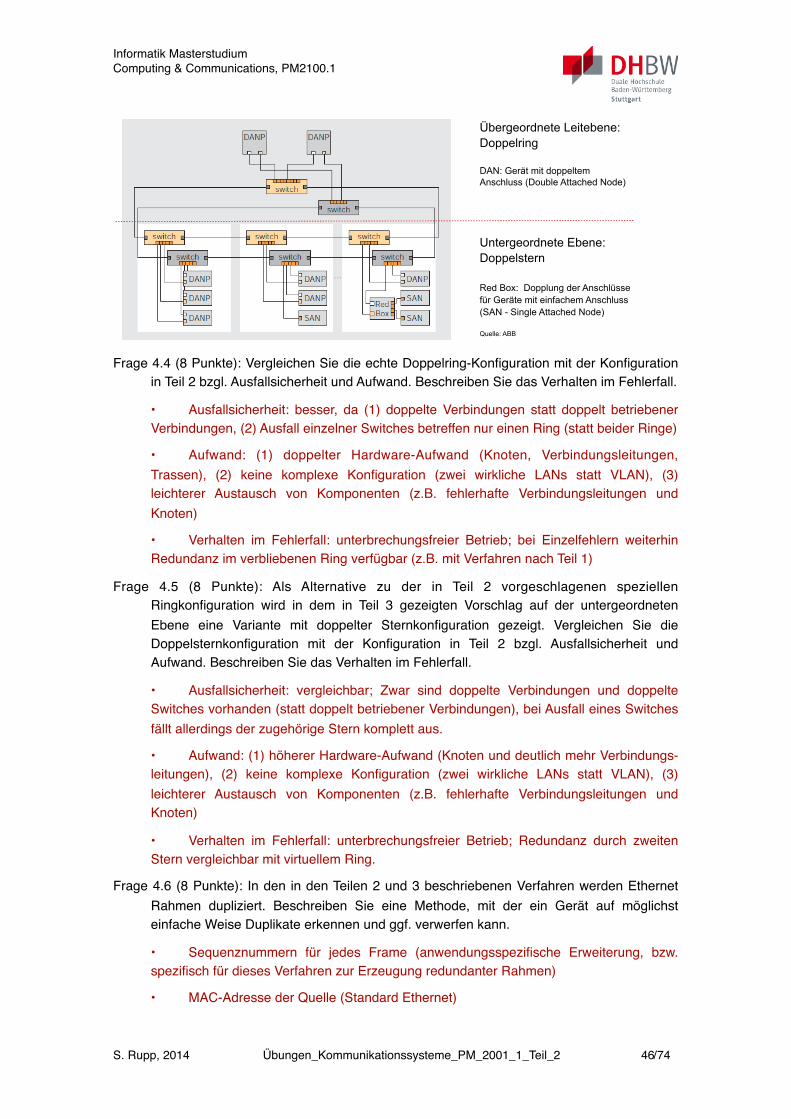
Übergeordnete Leitebene: Doppelring
DAN: Gerät mit doppeltem Anschluss (Double Attached Node)
Untergeordnete Ebene:Doppelstern
Red Box: Dopplung der Anschlüsse für Geräte mit einfachem Anschluss (SAN - Single Attached Node)
Quelle: ABB
Frage 4.4 (8 Punkte): Vergleichen Sie die echte Doppelring-Konfiguration mit der Konfiguration in Teil 2 bzgl. Ausfallsicherheit und Aufwand. Beschreiben Sie das Verhalten im Fehlerfall.
• Ausfallsicherheit: besser, da (1) doppelte Verbindungen statt doppelt betriebener Verbindungen, (2) Ausfall einzelner Switches betreffen nur einen Ring (statt beider Ringe)
• Aufwand: (1) doppelter Hardware-Aufwand (Knoten, Verbindungsleitungen, Trassen), (2) keine komplexe Konfiguration (zwei wirkliche LANs statt VLAN), (3) leichterer Austausch von Komponenten (z.B. fehlerhafte Verbindungsleitungen und Knoten)
• Verhalten im Fehlerfall: unterbrechungsfreier Betrieb; bei Einzelfehlern weiterhin Redundanz im verbliebenen Ring verfügbar (z.B. mit Verfahren nach Teil 1)
Frage 4.5 (8 Punkte): Als Alternative zu der in Teil 2 vorgeschlagenen speziellen Ringkonfiguration wird in dem in Teil 3 gezeigten Vorschlag auf der untergeordneten Ebene eine Variante mit doppelter Sternkonfiguration gezeigt. Vergleichen Sie die Doppelsternkonfiguration mit der Konfiguration in Teil 2 bzgl. Ausfallsicherheit und Aufwand. Beschreiben Sie das Verhalten im Fehlerfall.
• Ausfallsicherheit: vergleichbar; Zwar sind doppelte Verbindungen und doppelte Switches vorhanden (statt doppelt betriebener Verbindungen), bei Ausfall eines Switches fällt allerdings der zugehörige Stern komplett aus.
• Aufwand: (1) höherer Hardware-Aufwand (Knoten und deutlich mehr Verbindungs-leitungen), (2) keine komplexe Konfiguration (zwei wirkliche LANs statt VLAN), (3) leichterer Austausch von Komponenten (z.B. fehlerhafte Verbindungsleitungen und Knoten)
• Verhalten im Fehlerfall: unterbrechungsfreier Betrieb; Redundanz durch zweiten Stern vergleichbar mit virtuellem Ring.
Frage 4.6 (8 Punkte): In den in den Teilen 2 und 3 beschriebenen Verfahren werden Ethernet Rahmen dupliziert. Beschreiben Sie eine Methode, mit der ein Gerät auf möglichst einfache Weise Duplikate erkennen und ggf. verwerfen kann.
• Sequenznummern für jedes Frame (anwendungsspezifische Erweiterung, bzw. spezifisch für dieses Verfahren zur Erzeugung redundanter Rahmen)
• MAC-Adresse der Quelle (Standard Ethernet)
Informatik MasterstudiumComputing & Communications, PM2100.1
S. Rupp, 2014 Übungen_Kommunikationssysteme_PM_2001_1_Teil_2 46/74

• Rahmen von der gleichen Quelle mit gleicher Sequenznummer können verworfen werden.
• Bemerkungen: (1) Rahmen werden erst verworfen, nachdem der Empfang eines Duplikat festgestellt wurde. (2) Solch einfache Verfahren lassen sich hardware-nah implementieren. Auf Anwendungsebene gibt es natürlich weitere Möglichkeiten. (3) Das Verfahren sollte möglichst wenige falsch negative Identifikationen liefern, d.h. möglichst wenige gültige Rahmen, die irrtümlich als Duplikate verworfen werden. Hierzu ist erforderlich, dass einerseits die Tabellen mit gültigen Sequenznummern altern, andererseits die Sequenznummer hinreichend viele Stellen besitzt (z.B. 16 Bits), um fehlerhafte Identifikationen bedingt durch Zählerüberlauf auszuschließen.
Informatik MasterstudiumComputing & Communications, PM2100.1
S. Rupp, 2014 Übungen_Kommunikationssysteme_PM_2001_1_Teil_2 47/74
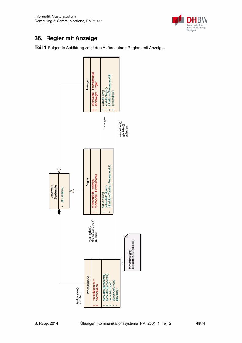
36. Regler mit AnzeigeTeil 1 Folgende Abbildung zeigt den Aufbau eines Reglers mit Anzeige.
«abs
tract
»Beobachter
+ ak
tual
isie
re()
Anzeige
+ m
einM
odel
l :P
roze
ssm
odel
l+
mei
nReg
ler
:Reg
ler
+ ak
tual
isie
re()
+ er
stel
leR
egle
r()+
initi
alis
iere
(Pro
zess
mod
ell)
+ pr
äsen
tiere
()
Regler
+ m
eine
Ansi
cht
:Anz
eige
+ m
einM
odel
l :P
roze
ssm
odel
l
+ ak
tual
isie
re()
+ be
hand
leEr
eign
is()
+ in
itial
isie
re(A
nzei
ge, P
roze
ssm
odel
l)
Prozessmodell
+ m
enge
Beob
acht
er+
proz
essD
aten
+ ab
mel
den(
Beob
acht
er)
+ an
mel
den(
Beob
acht
er)
+ be
nach
richt
ige(
)+
dien
stAu
sfüh
ren(
)+
gibD
aten
()
bena
chric
htig
e():
beob
acht
er.a
ktua
lisie
re()+a
nmel
den(
),di
enst
Ausf
ühre
n()
aufr
ufen
+Erz
euge
n
+anm
elde
n();
gibD
aten
()au
fruf
en
+akt
ualis
iere
()au
fruf
en
Informatik MasterstudiumComputing & Communications, PM2100.1
S. Rupp, 2014 Übungen_Kommunikationssysteme_PM_2001_1_Teil_2 48/74
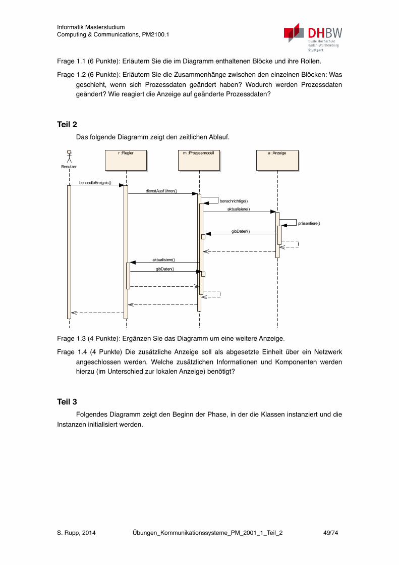
Frage 1.1 (6 Punkte): Erläutern Sie die im Diagramm enthaltenen Blöcke und ihre Rollen.
Frage 1.2 (6 Punkte): Erläutern Sie die Zusammenhänge zwischen den einzelnen Blöcken: Was geschieht, wenn sich Prozessdaten geändert haben? Wodurch werden Prozessdaten geändert? Wie reagiert die Anzeige auf geänderte Prozessdaten?
Teil 2 Das folgende Diagramm zeigt den zeitlichen Ablauf.
Benutzer
r :Regler a :Anzeigem :Prozessmodell
behandleEreignis()
dienstAusführen()
benachrichtige()
aktualisiere()
präsentiere()
gibDaten()
aktualisiere()
gibDaten()
Frage 1.3 (4 Punkte): Ergänzen Sie das Diagramm um eine weitere Anzeige.
Frage 1.4 (4 Punkte) Die zusätzliche Anzeige soll als abgesetzte Einheit über ein Netzwerk angeschlossen werden. Welche zusätzlichen Informationen und Komponenten werden hierzu (im Unterschied zur lokalen Anzeige) benötigt?
Teil 3 Folgendes Diagramm zeigt den Beginn der Phase, in der die Klassen instanziert und die
Instanzen initialisiert werden.
Informatik MasterstudiumComputing & Communications, PM2100.1
S. Rupp, 2014 Übungen_Kommunikationssysteme_PM_2001_1_Teil_2 49/74

Anwendung
m :Prozessmodell
a :Anzeige
r :Regler
new()
new()
initialisiere(Prozessmodell)
anmelden(Anzeige)
erstelleRegler()
Frage 1.5 (4 Punkte): Erläutern Sie den im Diagramm gezeigten Ablauf.
Frage 1.6 (4 Punkte): Ergänzen Sie das Diagramm um folgenden Ablauf: Nachdem sich die Anzeige beim Prozessmodell als Beobachter angemeldet hat, erzeugt das Anzeigeobjekt einen neuen Regler. Dem Regler werden bei der Initialisierung eine Referenz auf das Prozessmodell und auf die Anzeige übergegeben. Der Regler registriert sich ebenfalls als Beobachter beim Prozessmodell. Nach Abschluss der Initialisierung startet die Anwendung die Ereignisbehandlung (siehe Teil 2).
37. Topologie-ErkennungsdienstEin Hersteller von Systemen mit netzwerkbasierter Feldbusschnittstelle bietet eine
automatische Topologieerkennung an. Hiermit lässt sich die Netztopologie aus dem laufenden Netz auslesen, wie in folgender Abbildung 2.1 gezeigt. Damit dieser Dienst mit Geräten unterschiedlicher Hersteller funktioniert, basiert die Kommunikation unter den Geräten auf Basis eines internationalen Standards, nämlich dem in IEEE 802.1AB standardisierten Protokoll LLDP (Link Layer Discovery Protocol).
Informatik MasterstudiumComputing & Communications, PM2100.1
S. Rupp, 2014 Übungen_Kommunikationssysteme_PM_2001_1_Teil_2 50/74
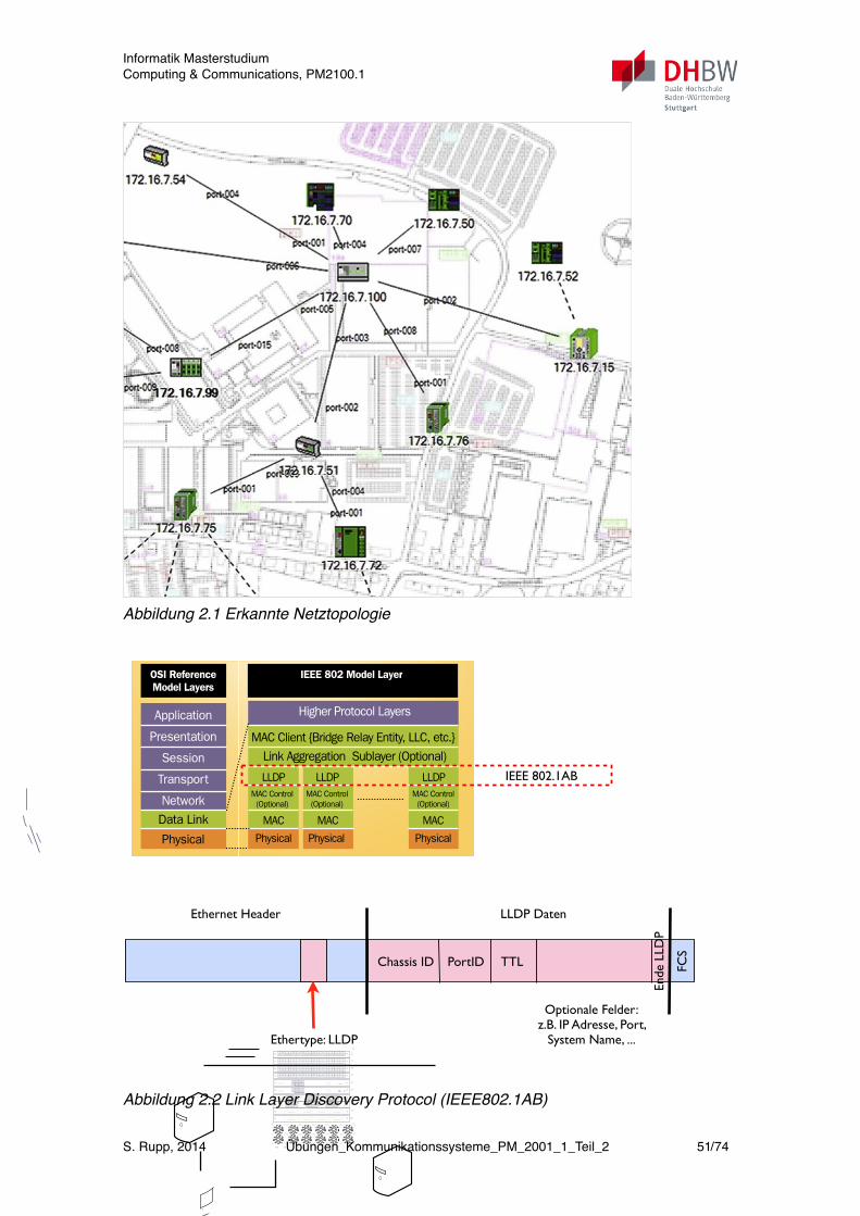
Abbildung 2.1 Erkannte Netztopologie
Application
OSI ReferenceModel Layers
IEEE 802 Model Layer
Presentation
Session
Transport
NetworkData Link
Physical
Higher Protocol Layers
MAC Client {Bridge Relay Entity, LLC, etc.}
Link Aggregation Sublayer (Optional)
LLDPMAC Control(Optional)
MAC Control(Optional)
MAC Control(Optional)
MAC
Physical Physical Physical
MAC MAC
LLDP LLDP
Extreme Networks Technical Brief
How LLDP Works
LLDP is essentially a neighbor discovery protocol that defines a method for network access devices using Ethernet connectivity to advertise information about them to peer devices on the same physical LAN and store information about the network. It allows a device to learn higher layer management reachability and connection endpoint informa-tion from adjacent devices. LLDP has been fully implement-ed in Extreme Networks switches and is accessible from the EPICenter® management system.
Using LLDP, an Extreme Networks device is able to advertise its own identification information, its capabilities and media-specific configuration information, as well as learn the same information from the devices connected to it. LLDP advertises this information over Logical Link-Layer Control frames and the information received from other agents in IEEE-defined Management Information Bases (MIB) modules. Figure 1 shows this relationship.
LLDP significantly aids in the deployment of any network device that supports the protocol. As a media independent protocol intended to be run on all IEEE 802 devices, LLDP may be used to discover routers, bridges, repeaters, WLAN APs, IP telephones, network camera or any LLDP-enabled device, regardless of manufacturer. Since LLDP runs over the data-link layer only, an Extreme Networks switch running one network layer protocol can discover and learn about an access device running a different network layer protocol.
LLDP Architecture
LLDP is a data-link layer protocol, operating above the MAC service layer and, as a result, can be used in any networking device that implements a MAC service. Figure 2 shows where LLDP resides in the IEEE 802 Model Layers.
© 2006 Extreme Networks, Inc. All rights reserved. Link Layer Discovery Protocol—Page 2
BlackDiamond 8810
BlackDiamond® 10808
Port Device InfoA13
C2
D2
F3
Switch
IP Phone
PC
IP-PBX
xxxx
xxxx
xxxx
xxxx
Discovery MIB
Intellegent Core
PSTN
LLDP—How it WorksThe IEEE 802.1ab Link Layer Discovery Protocol defines a standard way for Ethernet devices to advertise information about themselves to their network neighbors and store information they discover from other device.
LAN switch and router advertise chassis/port ids and system descriptions to each other.
The devices store the information they learn about each other in local MIB databases accessible via SNMP.
A network management system (Extreme Networks EPICenter) retrieves the data stored by each device that builds a network topology map.
1.
2.
3.
BlackDiamond 8810
Router
MIB
NetworkManagement
System
LAN Switch
MIB
IP Phone
1
2
3
`
Figure 2: LLDP Architecture
Figure 1: LLDP Peer Discovery
IEEE 802.1AB
Ethernet Header
Ethertype: LLDP
FCS
LLDP Daten
Chassis ID PortID TTL
Ende
LLD
P
Optionale Felder:z.B. IP Adresse, Port,
System Name, ...
Abbildung 2.2 Link Layer Discovery Protocol (IEEE802.1AB)
Informatik MasterstudiumComputing & Communications, PM2100.1
S. Rupp, 2014 Übungen_Kommunikationssysteme_PM_2001_1_Teil_2 51/74
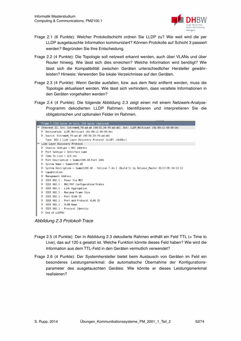
Frage 2.1 (6 Punkte): Welcher Protokollschicht ordnen Sie LLDP zu? Wie weit wird die per LLDP ausgetauschte Information kommuniziert? Können Protokolle auf Schicht 3 passiert werden? Begründen Sie Ihre Entscheidung.
Frage 2.2 (4 Punkte): Die Topologie soll netzweit erkannt werden, auch über VLANs und über Router hinweg. Wie lässt sich dies erreichen? Welche Information wird benötigt? Wie lässt sich die Kompatibilität zwischen Geräten unterschiedlicher Hersteller gewähr-leisten? Hinweis: Verwenden Sie lokale Verzeichnisse auf den Geräten.
Frage 2.3 (4 Punkte): Wenn Geräte ausfallen, bzw. aus dem Netz entfernt werden, muss die Topologie aktualisiert werden. Wie lässt sich verhindern, dass veraltete Informationen in den Geräten vorgehalten werden?
Frage 2.4 (4 Punkte): Die folgende Abbildung 2.3 zeigt einen mit einem Netzwerk-Analyse-Programm dekodierten LLDP Rahmen. Identifizieren und interpretieren Sie die obligatorischen und optionalen Felder im Rahmen.
Abbildung 2.3 Protokoll-Trace
Frage 2.5 (4 Punkte): Der in Abbildung 2.3 dekodierte Rahmen enthält ein Feld TTL (= Time to Live), das auf 120 s gesetzt ist. Welche Funktion könnte dieses Feld haben? Wie wird die Information aus dem TTL-Feld in den Geräten vermutlich verwendet?
Frage 2.6 (4 Punkte): Der Systemhersteller bietet beim Austausch von Geräten im Feld ein besonderes Leistungsmerkmal: die automatische Übernahme der Konfigurations-parameter des ausgetauschten Gerätes. Wie könnte er dieses Leistungsmerkmal realisieren?
Informatik MasterstudiumComputing & Communications, PM2100.1
S. Rupp, 2014 Übungen_Kommunikationssysteme_PM_2001_1_Teil_2 52/74
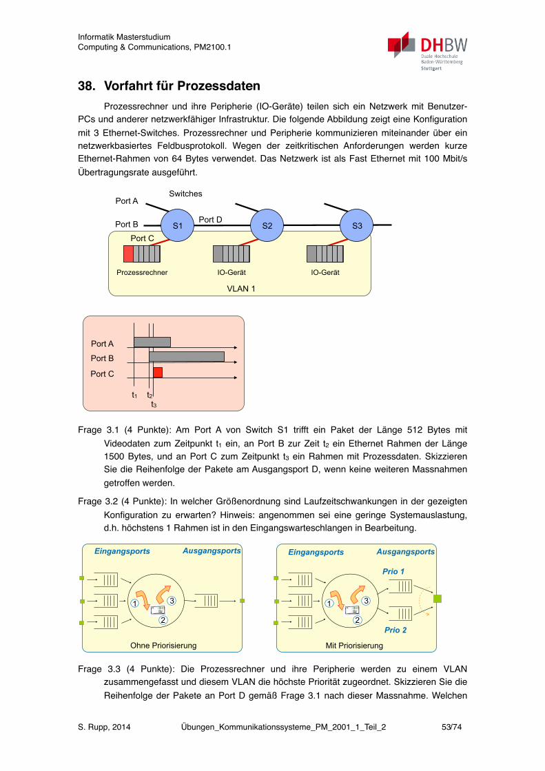
38. Vorfahrt für ProzessdatenProzessrechner und ihre Peripherie (IO-Geräte) teilen sich ein Netzwerk mit Benutzer-
PCs und anderer netzwerkfähiger Infrastruktur. Die folgende Abbildung zeigt eine Konfiguration mit 3 Ethernet-Switches. Prozessrechner und Peripherie kommunizieren miteinander über ein netzwerkbasiertes Feldbusprotokoll. Wegen der zeitkritischen Anforderungen werden kurze Ethernet-Rahmen von 64 Bytes verwendet. Das Netzwerk ist als Fast Ethernet mit 100 Mbit/s Übertragungsrate ausgeführt.
VLAN 1
SwitchesPort A
Port B
Port C S1 S2 S3
Port A
Port B
Port C
t1 t2t3
Port D
Prozessrechner IO-Gerät IO-Gerät
Frage 3.1 (4 Punkte): Am Port A von Switch S1 trifft ein Paket der Länge 512 Bytes mit Videodaten zum Zeitpunkt t1 ein, an Port B zur Zeit t2 ein Ethernet Rahmen der Länge 1500 Bytes, und an Port C zum Zeitpunkt t3 ein Rahmen mit Prozessdaten. Skizzieren Sie die Reihenfolge der Pakete am Ausgangsport D, wenn keine weiteren Massnahmen getroffen werden.
Frage 3.2 (4 Punkte): In welcher Größenordnung sind Laufzeitschwankungen in der gezeigten Konfiguration zu erwarten? Hinweis: angenommen sei eine geringe Systemauslastung, d.h. höchstens 1 Rahmen ist in den Eingangswarteschlangen in Bearbeitung.
1
2
3
Eingangsports
Prio 1
Ausgangsports
Prio 2
Mit Priorisierung
1
2
3
Eingangsports Ausgangsports
Ohne Priorisierung
Frage 3.3 (4 Punkte): Die Prozessrechner und ihre Peripherie werden zu einem VLAN zusammengefasst und diesem VLAN die höchste Priorität zugeordnet. Skizzieren Sie die Reihenfolge der Pakete an Port D gemäß Frage 3.1 nach dieser Massnahme. Welchen
Informatik MasterstudiumComputing & Communications, PM2100.1
S. Rupp, 2014 Übungen_Kommunikationssysteme_PM_2001_1_Teil_2 53/74

Einfluss hat diese Massnahme auf die Laufzeitschwankungen? Hinweis: Als zum VLAN gehörig markierten Pakete erhalten nach dem in der Abbildung oben gezeigten Mechanismus die höchste Priorität.
Frage 3.4 (6 Punkte): Könnte man durch Verwendung zusätzlicher Ausgangsports weitere Fortschritte erzielen? Begründen Sie Ihre Aussage. Nennen Sie Massnahmen, wie man die Laufzeitschwankungen weiter verringern könnte. Begründen Sie Ihre Aussagen.
39. Speicherprogrammierbare Steuerung (SPS)Eine Task innerhalb einer SPS arbeitet zyklisch nach folgendem Schema (1) Eingänge
abfragen, (2) Ausgänge berechnen, (3) Ausgänge schalten. Das Abfragen der Eingänge geschieht durch Empfang von Nachrichten von den Sensoren über einen Feldbus. Das Schalten der Ausgänge erfolgt durch Senden von Nachrichten an die Aktoren über den Feldbus.
Der Busmaster organisiert den Nachrichtenaustausch am Feldbus so, dass innerhalb eines Buszyklus Zeitpunkte für den Austausch von Meldungen zwischen den angeschlossenen Geräten vereinbart sind. Hierbei arbeitet der Feldbus also ebenfalls zyklisch, läuft jedoch nicht synchron mit dem Zyklus der SPS.
Die nachfolgende Abbildung zeigt den zeitlichen Ablauf.
1
1
2
2
3
3
N
N
8
8
1
1
2
2
3
3
N
N
8
8
1
1
2
2
3
3
N
N
8
8
Sensorsignal ändert sich
Sensorsignal wird gepuffert
Sensorsignal wird übertragen
2
8
Sensor: Gerät
Controller: Gerät
Steuerinformation an alle Aktoren
1
1
2
2
3
3
N
N
8
8
1
1
2
2
3
3
N
N
8
8
1
1
2
2
3
3
N
N
8
8
Sensorsignal ändert sich
BerechnungI O BerechnungI OSPS Zyklus
Sensorsignal wird gepuffert
Sensorsignal gelesen Steuersignal wird gepuffert
Steuerinformation an alle Aktoren
Sensorsignal wird gepuffert
Frage 1: Welchen Einfluss hat der Buszyklus auf die Weitergabe der Meldungen an die angeschlossenen Sender und Empfänger im Feld? Welche Verzögerung (gemessen in Bus-Zyklen) ergibt sich zwischen Senden einer Sensormeldung und Empfangen der Steuermeldung am Aktor aus Perspektive des Busses?
Frage 2: Erläutern Sie den prinzipiellen Ablauf für den Empfang und das Senden von Meldungen aus dem Feld aus der Perspektive der SPS.
Informatik MasterstudiumComputing & Communications, PM2100.1
S. Rupp, 2014 Übungen_Kommunikationssysteme_PM_2001_1_Teil_2 54/74
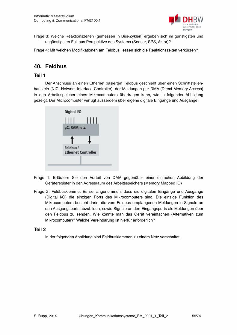
Frage 3: Welche Reaktionszeiten (gemessen in Bus-Zyklen) ergeben sich im günstigsten und ungünstigsten Fall aus Perspektive des Systems (Sensor, SPS, Aktor)?
Frage 4: Mit welchen Modifikationen am Feldbus liessen sich die Reaktionszeiten verkürzen?
40. FeldbusTeil 1
Der Anschluss an einen Ethernet basierten Feldbus geschieht über einen Schnittstellen-baustein (NIC, Network Interface Controller), der Meldungen per DMA (Direct Memory Access) in den Arbeitsspeicher eines Mikrocomputers übertragen kann, wie in folgender Abbildung gezeigt. Der Microcomputer verfügt ausserdem über eigene digitale Eingänge und Ausgänge.
Frage 1: Erläutern Sie den Vorteil von DMA gegenüber einer einfachen Abbildung der Geräteregister in den Adressraum des Arbeitsspeichers (Memory Mapped IO)
Frage 2: Feldbusklemme: Es sei angenommen, dass die digitalen Eingänge und Ausgänge (Digital I/O) die einzigen Ports des Mikrocomputers sind. Die einzige Funktion des Mikrocomputers besteht darin, die vom Feldbus empfangenen Meldungen in Signale an den Ausgangsports abzubilden, sowie Signale an den Eingangsports als Meldungen über den Feldbus zu senden. Wie könnte man das Gerät vereinfachen (Alternativen zum Mikrocomputer)? Welche Vereinbarung ist hierfür erforderlich?
Teil 2In der folgenden Abbildung sind Feldbusklemmen zu einem Netz verschaltet.
Informatik MasterstudiumComputing & Communications, PM2100.1
S. Rupp, 2014 Übungen_Kommunikationssysteme_PM_2001_1_Teil_2 55/74
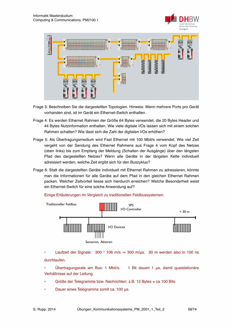
Frage 3: Beschreiben Sie die dargestellten Topologien. Hinweis: Wenn mehrere Ports pro Gerät vorhanden sind, ist im Gerät ein Ethernet-Switch enthalten.
Frage 4: Es werden Ethernet Rahmen der Größe 64 Bytes verwendet, die 20 Bytes Header und 44 Bytes Nutzinformation enthalten. Wie viele digitale I/Os lassen sich mit einem solchen Rahmen schalten? Wie lässt sich die Zahl der digitalen I/Os erhöhen?
Frage 5: Als Übertragungsmedium wird Fast Ethernet mit 100 Mbit/s verwendet. Wie viel Zeit vergeht von der Sendung des Ethernet Rahmens aus Frage 4 vom Kopf des Netzes (oben links) bis zum Empfang der Meldung (Schalten der Ausgänge) über den längsten Pfad des dargestellten Netzes? Wenn alle Geräte in der längsten Kette individuell adressiert werden, welche Zeit ergibt sich für den Buszyklus?
Frage 6: Statt die dargestellten Geräte individuell mit Ethernet Rahmen zu adressieren, könnte man die Informationen für alle Geräte auf dem Pfad in den gleichen Ethernet Rahmen packen. Welcher Zeitvorteil liesse sich hierdurch erreichen? Welche Besonderheit weist ein Ethernet-Switch für eine solche Anwendung auf?
Einige Erläuterungen im Vergleich zu traditionellen Feldbussystemen:
Traditioneller Feldbus SPS I/O Controller
I/O Devices
Sensoren, Aktoren
< 30 m
• Laufzeit der Signale: 300 * 106 m/s ⇒ 300 m/μs. 30 m werden also in 100 ns
durchlaufen.
• Übertragungsrate am Bus: 1 Mbit/s. 1 Bit dauert 1 μs, damit quaistationäre Verhältnisse auf der Leitung.
• Größe der Telegramme bzw. Nachrichten: z.B. 12 Bytes = ca 100 Bits
• Dauer eines Telegramms somit ca. 100 μs.
Informatik MasterstudiumComputing & Communications, PM2100.1
S. Rupp, 2014 Übungen_Kommunikationssysteme_PM_2001_1_Teil_2 56/74
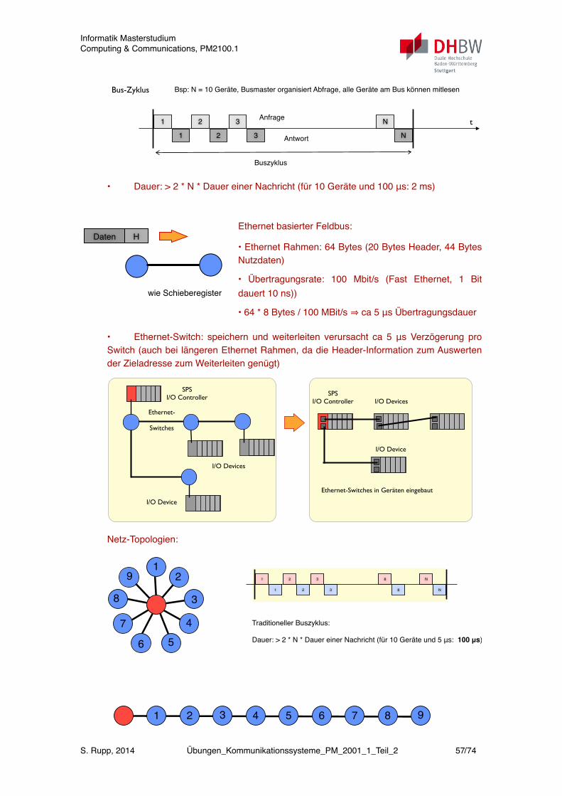
Bus-Zyklus Bsp: N = 10 Geräte, Busmaster organisiert Abfrage, alle Geräte am Bus können mitlesen
t1
1
2
2
3
3
Anfrage
Antwort
N
N
Buszyklus
• Dauer: > 2 * N * Dauer einer Nachricht (für 10 Geräte und 100 μs: 2 ms)
Ethernet basierter Feldbus:
• Ethernet Rahmen: 64 Bytes (20 Bytes Header, 44 Bytes Nutzdaten)
• Übertragungsrate: 100 Mbit/s (Fast Ethernet, 1 Bit dauert 10 ns))
• 64 * 8 Bytes / 100 MBit/s ⇒ ca 5 μs Übertragungsdauer
• Ethernet-Switch: speichern und weiterleiten verursacht ca 5 μs Verzögerung pro Switch (auch bei längeren Ethernet Rahmen, da die Header-Information zum Auswerten der Zieladresse zum Weiterleiten genügt)
SPS I/O Controller
I/O Devices
I/O Device
Ethernet-
Switches
SPS I/O Controller I/O Devices
I/O Device
Ethernet-Switches in Geräten eingebaut
Netz-Topologien:
1 2 5 84 73 6 9
4
3
21
9
8
7
6 5
1
1
2
2
3
3
N
N
8
8
Traditioneller Buszyklus:
Dauer: > 2 * N * Dauer einer Nachricht (für 10 Geräte und 5 μs: 100 μs)
Daten H
wie Schieberegister
Informatik MasterstudiumComputing & Communications, PM2100.1
S. Rupp, 2014 Übungen_Kommunikationssysteme_PM_2001_1_Teil_2 57/74
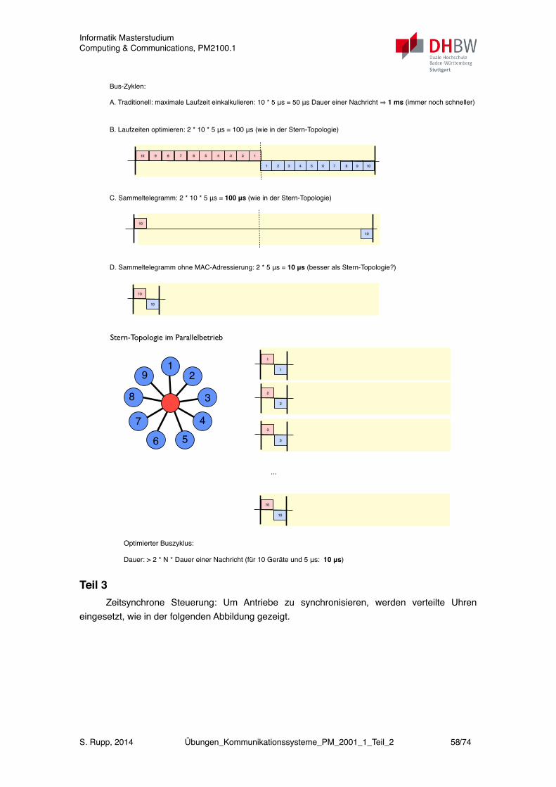
Bus-Zyklen:
A. Traditionell: maximale Laufzeit einkalkulieren: 10 * 5 μs = 50 μs Dauer einer Nachricht ⇒ 1 ms (immer noch schneller)
B. Laufzeiten optimieren: 2 * 10 * 5 μs = 100 μs (wie in der Stern-Topologie)
10
10
9
9
8
8
17 6 5 4 3 2
1 765432
C. Sammeltelegramm: 2 * 10 * 5 μs = 100 μs (wie in der Stern-Topologie)
10
10
D. Sammeltelegramm ohne MAC-Adressierung: 2 * 5 μs = 10 μs (besser als Stern-Topologie?)
10
10
Stern-Topologie im Parallelbetrieb
4
3
21
9
8
7
6 5
1
1
Optimierter Buszyklus:
Dauer: > 2 * N * Dauer einer Nachricht (für 10 Geräte und 5 μs: 10 μs)
2
2
3
3
10
10
...
Teil 3Zeitsynchrone Steuerung: Um Antriebe zu synchronisieren, werden verteilte Uhren
eingesetzt, wie in der folgenden Abbildung gezeigt.
Informatik MasterstudiumComputing & Communications, PM2100.1
S. Rupp, 2014 Übungen_Kommunikationssysteme_PM_2001_1_Teil_2 58/74
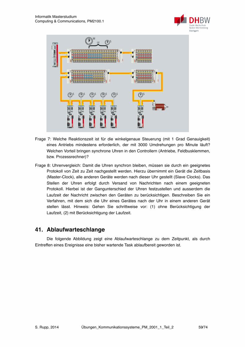
Frage 7: Welche Reaktionszeit ist für die winkelgenaue Steuerung (mit 1 Grad Genauigkeit) eines Antriebs mindestens erforderlich, der mit 3000 Umdrehungen pro Minute läuft? Welchen Vorteil bringen synchrone Uhren in den Controllern (Antriebe, Feldbusklemmen, bzw. Prozessrechner)?
Frage 8: Uhrenvergleich: Damit die Uhren synchron bleiben, müssen sie durch ein geeignetes Protokoll von Zeit zu Zeit nachgestellt werden. Hierzu übernimmt ein Gerät die Zeitbasis (Master-Clock), alle anderen Geräte werden nach dieser Uhr gestellt (Slave Clocks). Das Stellen der Uhren erfolgt durch Versand von Nachrichten nach einem geeigneten Protokoll. Hierbei ist der Gangunterschied der Uhren festzustellen und ausserdem die Laufzeit der Nachricht zwischen den Geräten zu berücksichtigen. Beschreiben Sie ein Verfahren, mit dem sich die Uhr eines Gerätes nach der Uhr in einem anderen Gerät stellen lässt. Hinweis: Gehen Sie schrittweise vor: (1) ohne Berücksichtigung der Laufzeit, (2) mit Berücksichtigung der Laufzeit.
41. AblaufwarteschlangeDie folgende Abbildung zeigt eine Ablaufwarteschlange zu dem Zeitpunkt, als durch
Eintreffen eines Ereignisse eine bisher wartende Task ablaufbereit geworden ist.
Informatik MasterstudiumComputing & Communications, PM2100.1
S. Rupp, 2014 Übungen_Kommunikationssysteme_PM_2001_1_Teil_2 59/74
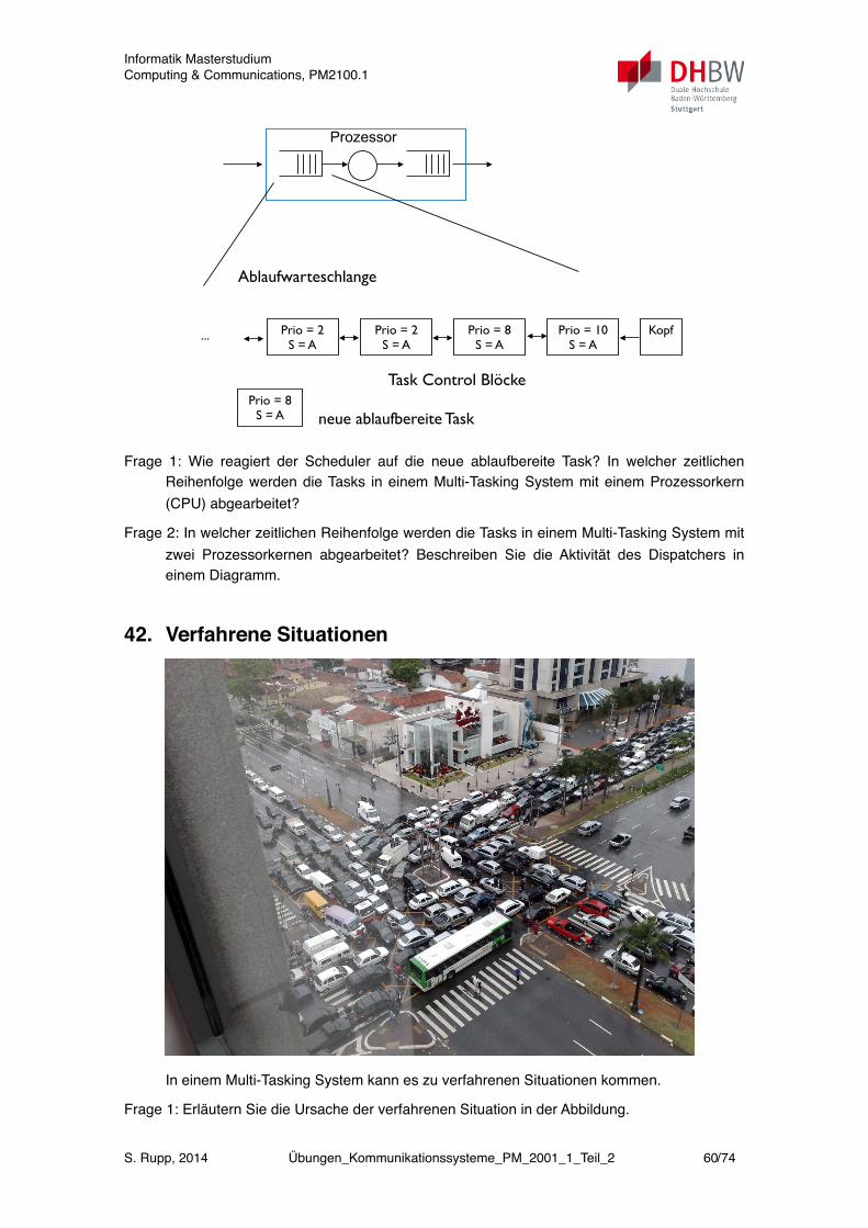
Prozessor
Ablaufwarteschlange
Task Control Blöcke
Prio = 2S = A
Prio = 8S = A
Prio = 2S = A
Prio = 10S = A
Kopf
Prio = 8S = A neue ablaufbereite Task
...
Frage 1: Wie reagiert der Scheduler auf die neue ablaufbereite Task? In welcher zeitlichen Reihenfolge werden die Tasks in einem Multi-Tasking System mit einem Prozessorkern (CPU) abgearbeitet?
Frage 2: In welcher zeitlichen Reihenfolge werden die Tasks in einem Multi-Tasking System mit zwei Prozessorkernen abgearbeitet? Beschreiben Sie die Aktivität des Dispatchers in einem Diagramm.
42. Verfahrene Situationen
In einem Multi-Tasking System kann es zu verfahrenen Situationen kommen.
Frage 1: Erläutern Sie die Ursache der verfahrenen Situation in der Abbildung.
Informatik MasterstudiumComputing & Communications, PM2100.1
S. Rupp, 2014 Übungen_Kommunikationssysteme_PM_2001_1_Teil_2 60/74

Frage 2: Wodurch entstehen solche Situationen in einem Multi-Tasking System? Wie lassen sich solche Situationen vermeiden? Wie lassen sie sich auflösen?
43. Task-SynchronisationTeil 1
Folgendes Diagramm zeigt den Ablauf zweier Tasks.
Frage 1: Erläutern Sie den Ablauf. Was genau wird durch die Verwendung der Ereignis-meldungen (Event Flags) erreicht?
Frage 2: Eine Abfüllanlage soll mit Hilfe dreier paralleler Tasks realisiert werden: (1) Flasche abfüllen, (2) Kronkorken aufsetzen, (3) Etikett aufkleben. Die Aufgaben sollen in auf einander folgenden Arbeitsschritten erledigt werden. Erstellen Sie ein Aktivitäts-diagramm.
Task P1
EventFlag2
Fork P2
InitialisierungSchleife
EventFlag1 zurück setzen
Schalter"Aus"betätigt?
Ende P1
Initialisierung
EventFlag1
Abschnitt A bearbeiten
EventFlag1
Schleife
EventFlag2 zurück setzen
EventFlag2
Abschnitt B bearbeiten
Teil 2Drei Antriebsachsen sollen synchronisiert werden. Jede Antriebsachse soll mit Hilfe einer
eigenen Task gesteuert werden. Bezugspunkt für jede Achse ist eine vorgegebene Position, die von einem Drehgeber gemeldet wird. Durchläuft die Achse diesen Bezugspunkt, wird ein Alarm erzeugt.
Informatik MasterstudiumComputing & Communications, PM2100.1
S. Rupp, 2014 Übungen_Kommunikationssysteme_PM_2001_1_Teil_2 61/74
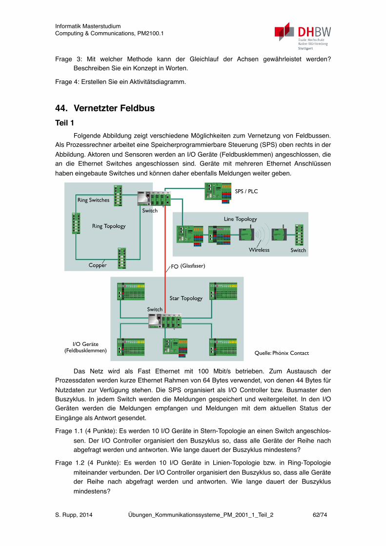
Frage 3: Mit welcher Methode kann der Gleichlauf der Achsen gewährleistet werden? Beschreiben Sie ein Konzept in Worten.
Frage 4: Erstellen Sie ein Aktivitätsdiagramm.
44. Vernetzter FeldbusTeil 1
Folgende Abbildung zeigt verschiedene Möglichkeiten zum Vernetzung von Feldbussen. Als Prozessrechner arbeitet eine Speicherprogrammierbare Steuerung (SPS) oben rechts in der Abbildung. Aktoren und Sensoren werden an I/O Geräte (Feldbusklemmen) angeschlossen, die an die Ethernet Switches angeschlossen sind. Geräte mit mehreren Ethernet Anschlüssen haben eingebaute Switches und können daher ebenfalls Meldungen weiter geben.
Ring Switches
I/O Geräte (Feldbusklemmen)
Switch
Switch
(Glasfaser)
SPS / PLC
Switch
Quelle: Phönix Contact
Das Netz wird als Fast Ethernet mit 100 Mbit/s betrieben. Zum Austausch der Prozessdaten werden kurze Ethernet Rahmen von 64 Bytes verwendet, von denen 44 Bytes für Nutzdaten zur Verfügung stehen. Die SPS organisiert als I/O Controller bzw. Busmaster den Buszyklus. In jedem Switch werden die Meldungen gespeichert und weitergeleitet. In den I/O Geräten werden die Meldungen empfangen und Meldungen mit dem aktuellen Status der Eingänge als Antwort gesendet.
Frage 1.1 (4 Punkte): Es werden 10 I/O Geräte in Stern-Topologie an einen Switch angeschlos-sen. Der I/O Controller organisiert den Buszyklus so, dass alle Geräte der Reihe nach abgefragt werden und antworten. Wie lange dauert der Buszyklus mindestens?
Frage 1.2 (4 Punkte): Es werden 10 I/O Geräte in Linien-Topologie bzw. in Ring-Topologie miteinander verbunden. Der I/O Controller organisiert den Buszyklus so, dass alle Geräte der Reihe nach abgefragt werden und antworten. Wie lange dauert der Buszyklus mindestens?
Informatik MasterstudiumComputing & Communications, PM2100.1
S. Rupp, 2014 Übungen_Kommunikationssysteme_PM_2001_1_Teil_2 62/74
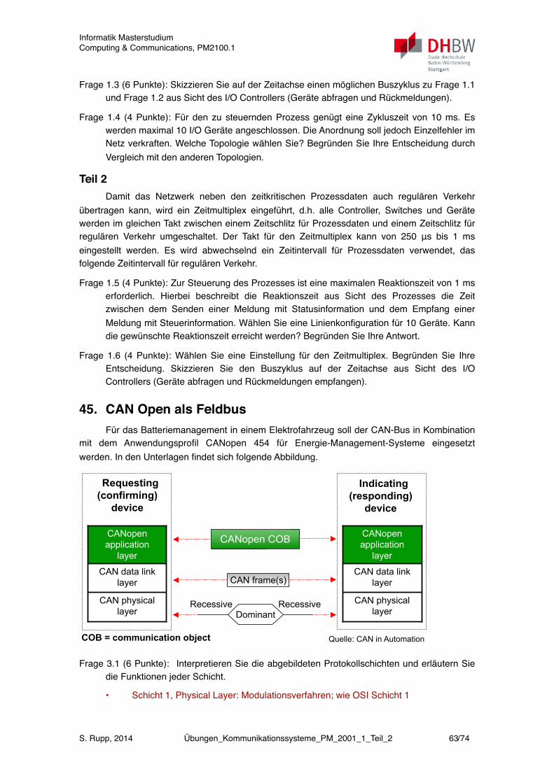
Frage 1.3 (6 Punkte): Skizzieren Sie auf der Zeitachse einen möglichen Buszyklus zu Frage 1.1 und Frage 1.2 aus Sicht des I/O Controllers (Geräte abfragen und Rückmeldungen).
Frage 1.4 (4 Punkte): Für den zu steuernden Prozess genügt eine Zykluszeit von 10 ms. Es werden maximal 10 I/O Geräte angeschlossen. Die Anordnung soll jedoch Einzelfehler im Netz verkraften. Welche Topologie wählen Sie? Begründen Sie Ihre Entscheidung durch Vergleich mit den anderen Topologien.
Teil 2Damit das Netzwerk neben den zeitkritischen Prozessdaten auch regulären Verkehr
übertragen kann, wird ein Zeitmultiplex eingeführt, d.h. alle Controller, Switches und Geräte werden im gleichen Takt zwischen einem Zeitschlitz für Prozessdaten und einem Zeitschlitz für regulären Verkehr umgeschaltet. Der Takt für den Zeitmultiplex kann von 250 μs bis 1 ms eingestellt werden. Es wird abwechselnd ein Zeitintervall für Prozessdaten verwendet, das folgende Zeitintervall für regulären Verkehr.
Frage 1.5 (4 Punkte): Zur Steuerung des Prozesses ist eine maximalen Reaktionszeit von 1 ms erforderlich. Hierbei beschreibt die Reaktionszeit aus Sicht des Prozesses die Zeit zwischen dem Senden einer Meldung mit Statusinformation und dem Empfang einer Meldung mit Steuerinformation. Wählen Sie eine Linienkonfiguration für 10 Geräte. Kann die gewünschte Reaktionszeit erreicht werden? Begründen Sie Ihre Antwort.
Frage 1.6 (4 Punkte): Wählen Sie eine Einstellung für den Zeitmultiplex. Begründen Sie Ihre Entscheidung. Skizzieren Sie den Buszyklus auf der Zeitachse aus Sicht des I/O Controllers (Geräte abfragen und Rückmeldungen empfangen).
45. CAN Open als FeldbusFür das Batteriemanagement in einem Elektrofahrzeug soll der CAN-Bus in Kombination
mit dem Anwendungsprofil CANopen 454 für Energie-Management-Systeme eingesetzt werden. In den Unterlagen findet sich folgende Abbildung.
CAN
© CiA
CANopen application layer
COB = communication object
Indicating(responding)
device
CANopen COB
CAN frame(s)
Requesting(confirming)
device
Recessive RecessiveDominant
CAN physical
layer
CAN data link
layer
CANopen
application
layer
CAN physical
layer
CAN data link
layer
CANopen
application
layer
Quelle: CAN in Automation
Frage 3.1 (6 Punkte): Interpretieren Sie die abgebildeten Protokollschichten und erläutern Sie die Funktionen jeder Schicht.
• Schicht 1, Physical Layer: Modulationsverfahren; wie OSI Schicht 1
Informatik MasterstudiumComputing & Communications, PM2100.1
S. Rupp, 2014 Übungen_Kommunikationssysteme_PM_2001_1_Teil_2 63/74

• Schicht 2, Data Link: Rahmenprotokoll mit Fehlerkorrektur; wie OSI-Schicht 2
• Schicht 3, Anwendungsschicht: Schnittstelle für den Anwendungsprogrammierer, Definition von Nachrichten, Nachrichtenformaten und Objekten aus der Anwendungs-domaine; entspricht OSI Schicht 7
Frage 3.2 (8 Punkte): CAN funktioniert als serieller Feldbus, d.h. alle Geräte sind an einem gemeinsamen Medium (Zweidraht) angeschlossen. Der Anschluss der Geräte an den Feldbus erfolgt wie in folgender Abbildung gezeigt. Erläutern Sie die Funktion der einzelnen Komponenten im Zusammenhang mit den den Protokollschichten aus der letzten Abbildung. Welche Besonderheit hat der dargestellte Mikrocontroller?
CAN
© CiA
• Signaling
• Bus Failure
Management
MicrocontrollerCAN Transceiver
CAN_H
CAN_L
Rx
Tx
CAN Module• Protocol Controller
• Message Filter
• Message Buffer
• CPU Interface
CPU Module
• Additional Message Filter• Higher Layer
Protocol
• Application
Integrated CAN module
Quelle: CAN in Automation
• CAN-Transceiver: Physical Layer, stellt für Schicht 2 eine Schnittstelle zum Senden (Transmit Tx) und Empfangen (Receive Rx) von Nachrichten zur Verfügung.
• CAN Module: Schicht 2; sowie Vorverarbeitung von Signalen, z.B. Ausfiltern relevanter Signale zur weiteren Verarbeitung, sowie Nachrichtenpuffer; stellt Schnittstelle zur Anwendungsschicht bereit.
• CPU-Module: Verarbeitung des Anwendungsprotokolls (Schicht 3), sowie der der Anwendung selbst.
• In der gezeigten Abbildung ist das CAN-Module (Schnittstellenmodul) direkt im Mikrocontroller integriert. Als Alternative wäre ein externer Baustein zu verwenden, der dann über eine serielle Schnittstelle an einen Mikrocontroller angeschlossen ist (z.B. über eine serielle Schnittstelle wie SPI).
Frage 3.3 (8 Punkte): Der Feldbus wird mit einer Datenrate von 1 Mbit/s betrieben. Die Länge einer Nachricht beträgt 6 Bytes für den Nachrichtenkopf (Header), sowie 0 bis 8 Bytes für Daten. Die Geräte kommunizieren Kollisionen unter einander (mehrere Geräte senden gleichzeitig), sowie Quittungen empfangener Nachrichten unmittelbar durch den Signalpegel eines einzelnen Bits (in Art einer Open-Kollektor-Schaltung bzw. verdrahteter ODER-Logik der Anschlüsse an den Bus). Wie lange darf die Länge ℓ des Feldbusses höchstens sein, damit eine Nachricht von einem Ende zum anderen laufen kann und von dort eine Quittung empfangen werden kann (als Ausbreitungsgeschwindigkeit seien 200 * 106 m/s angenommen)? Wie viele Nachrichten pro Sekunde kann der Bus übertragen, wenn jede Nachricht 8 Bytes Daten enthält? Nennen Sie eine Möglichkeiten, Nachrichten bevorzugt zu behandeln (z.B. Steuerinformationen vor Messwerten).
• Die Übertragungsdauer eines Bits beträgt 1 us (zu berechnen aus der Datenrate). Während dieser Zeit wird mit der gegebenen Ausbreitungsgeschwindigkeit eine Ent-
Informatik MasterstudiumComputing & Communications, PM2100.1
S. Rupp, 2014 Übungen_Kommunikationssysteme_PM_2001_1_Teil_2 64/74

fernung von 200 m durchlaufen. Die Buslänge darf also 100 m nicht überschreiten, damit eine Quittung nach einer us zurücklaufen kann. Damit die Quittung innerhalb der Bitdauer ankommt, sollte die Buslänge deutlich kürzer sein (max. 40 m).
• Nachrichtenlänge: 14 Bytes = 14 * 8 = 112 bits => 112 us pro Nachricht. Somit können pro Sekunde 8929 Nachrichten übertragen werden.
• Die Priorität der Nachricht wird im Nachrichtenkopf kennzeichnen. Die Auswertung erfolgt entweder durch die Anwendung (Software im Mikrocontroller), bzw. gleich bitweise durch den Buspegel.
Informatik MasterstudiumComputing & Communications, PM2100.1
S. Rupp, 2014 Übungen_Kommunikationssysteme_PM_2001_1_Teil_2 65/74
Englisch - Deutsch
Admission control ! ! ! Zulassungskontrolle
Air Interface! ! ! ! Funkschnittstelle
Application layer! ! ! Anwendungsschicht, Verarbeitungsschicht
Basic Services (BS) ! ! ! Basisdienste
Bearer Service ! ! ! ! Trägerdienst
Block Error Rate! ! ! Blockfehlerrate
Broadcast ! ! ! ! Rundsendung
Call Control ! ! ! ! Rufsteuerung
Call Drop Rate !! ! ! Verbindungsabbruchrate
Call Forwarding (CF) ! ! ! Rufumleitung
Carrier !! ! ! ! Verbindungsnetzbetreiber
Cell Identity (CID) ! ! ! Zellkennung
Circuit switched domain!! ! Leitungsvermittelte Domäne
Circuit switching! ! ! Leitungsvermittlung
Confidentiality! ! ! ! Vertraulichkeit
Content Provider ! ! ! Inhalteanbieter
Control Plane ! ! ! ! Steuerungsebene
Core Network ! ! ! ! Kernnetz
Credentials ! ! ! ! Beglaubigung, Zeugnis
Data Link Layer ! ! ! Sicherungsschicht
Delay, Latency !! ! ! Verzögerung, Laufzeit
Downlink! ! ! ! Abwärtsstrecke
Echo Canceller! ! ! ! Echokompensator
Expedited Forwarding! ! ! beschleunigtes Weiterleiten
Fading! ! ! ! ! Schwund
Firewall!! ! ! ! Brandschutzmauer, Paketfilter
Frame Error Rate! ! ! Rahmenfehlerrate
Frequency Division Multiple Access! Frequenzvielfachzugriff
Handover, Handoff! ! ! (Verbindungs-)Übergabe, Weiterreichen
Integrity! ! ! ! Unversehrtheit (von Daten bzw. Systemen)
Jitter! ! ! ! ! Laufzeitschwankungen
Line of Sight! ! ! ! Sichtverbindung
Informatik MasterstudiumComputing & Communications, PM2100.1
S. Rupp, 2014 Übungen_Kommunikationssysteme_PM_2001_1_Teil_2 66/74

Local Area Network! ! ! Lokales Rechnernetz
Location Area (LA)! ! ! Aufenthaltsbereich
Mobile Termination! ! ! Mobilfunk-Netzabschluss
Mobility Management! ! ! Mobilitätssteuerung
Multicast! ! ! ! Vielfachsendung
narrowband! ! ! ! schmalbandig
Network Layer! ! ! ! Vermittlungsschicht
Packet Loss! ! ! ! Paketverlust
Packet Switching ! ! ! Paketvermittlung
Penetration Loss! ! ! Wanddämpfungsverlust
Physical Layer! ! ! ! Physikalische Schicht
Power Control! ! ! ! Leistungsregelung
Presence Service! ! ! Erreichbarkeitsdienst
Processing Gain! ! ! Prozessgewinn
Pseudo Noise Sequence ! ! Pseudozufallsfolge
Push Service! ! ! ! Zustelldienst
Quality of Service! ! ! Dienstgüte
Release! ! ! ! Ausgabe (eines Normenpaketes oder Softwarepaketes)
Resource Management!! ! Administration der Betriebsmittel
Resources! ! ! ! Betriebsmittel
Routing!! ! ! ! Verkehrslenkung
Scrambling! ! ! ! Verwürfelung
Sensitivity! ! ! ! Empfindlichkeit
Service Provider ! ! ! Dienstanbieter, Diensterbringer
Session ! ! ! ! Sitzung
Session Layer! ! ! ! Sitzungsschicht
Session Management! ! ! Sitzungssteuerung
Short Message!! ! ! Kurznachricht
State Event Diagram! ! ! Zustandsübergangsdiagramm
Subframe! ! ! ! Teilrahmen
Sublayer! ! ! ! Teilschicht
Subscription! ! ! ! Vertragsabschluss, Subskription, Diensteinschreibung
Supplementary Services (SS)! ! Zusatzdienste
Terminal Equipment! ! ! Endgerät
Informatik MasterstudiumComputing & Communications, PM2100.1
S. Rupp, 2014 Übungen_Kommunikationssysteme_PM_2001_1_Teil_2 67/74

Time Division Multiple Access! ! Zeitvielfachzugriff
Traffic Model! ! ! ! Verkehrsmodell
Transcoding! ! ! ! Umcodierung
Transport Layer!! ! ! Transportschicht
Uplink! ! ! ! ! Aufwärtsstrecke
User Equipment! ! ! Teilnehmerausrüstung
User Plane! ! ! ! Nutzerebene
Informatik MasterstudiumComputing & Communications, PM2100.1
S. Rupp, 2014 Übungen_Kommunikationssysteme_PM_2001_1_Teil_2 68/74
Abkürzungen
2G ! ! 2nd Generation (of Mobile Radio)
3G ! ! 3rd Generation (of Mobile Radio)
3GPP! ! 3rd Generation Partnership Project (UMTS)
AAA! ! Authentication, Authorization, Accounting
ADSL ! ! Asynchronous Digital Subscriber Line
AG ! ! Access Gateway
AP! ! Access Point
API! ! Application Programming Interface
ASP! ! Application Service Provider
AuC! ! Authentication Center
BER! ! Bit Error Rate
BLER ! ! Block Error Rate
BSC! ! Base Station Controller
BSS! ! Base Station System
BTS! ! Base Transceiver Station
CCBS! ! Customer Care and Billing System
CDMA! ! Code Division Multiple Access
CK! ! Ciphering Key
CORBA! Common Object Request Broker Architecture
CPE! ! Customer Premises Equipment
DECT! ! Digital Enhanced Cordless Telecommunications
DHCP! ! Dynamic Host Configuration Protocol
DIAMETER! successor to RADIUS
DNS! ! Domain Name Service
DSL! ! Digital Subscriber Line
DVB ! ! Digital Video Broadcasting
DVB-S! ! Satellite DVB
DVB-T! ! Terrestrial DVB
EDGE! ! Enhanced Data Rates for Global Evolution
EIR! ! Equipment Identity Register
ERAN ! ! EDGE Radio Access Network
ETSI! ! European Telecommunications Standards Institute
Informatik MasterstudiumComputing & Communications, PM2100.1
S. Rupp, 2014 Übungen_Kommunikationssysteme_PM_2001_1_Teil_2 69/74

EU ! ! European Union
FDD! ! Frequency Division Duplex
FDMA! ! Frequency Division Multiple Access
FEC ! ! Forward Error Correction
FER ! ! Frame Error Rate
FTP! ! File Transfer Protocol
GERAN! GSM/EDGE Radio Access Network
GGSN! ! Gateway GPRS Support Node
GMLC ! ! Gateway Mobile Location Center
G-MS! ! Gateway MSC
GPRS! ! General Packet Radio Service GPS: Global Positioning System
GSM! ! Global System for Mobile communication
HDTV! ! High Definition Television
HLR ! ! Home Location Register
HSS! ! Home Subscriber Server
HTTP! ! Hypertext Transfer Protocol
IAM! ! Initial Access Message
ID! ! Identity
IDL! ! Interface Description Language
IEEE! ! Institute of Electrical and Electronics Engineers
IETF! ! Internet Engineering Task Force
IM ! ! Instant Messaging
IMEI! ! International Mobile Equipment Identity
IMSI! ! International Mobile Subscriber Identity
IN ! ! Intelligent Network
INAP! ! Intelligent Network Application Part
IP! ! Internet Protocol
IPsec! ! IP Security Protocol
IP-VPN!! IP Virtual Private Network
ISDN ! ! Integrated Services Digital Network
ISO! ! International Organization for Standardization ISP: Internet Service Provider
IT! ! Informations Technologie
ITU ! ! International Telecommunication Union
J2ME! ! Java 2 Micro Edition
Informatik MasterstudiumComputing & Communications, PM2100.1
S. Rupp, 2014 Übungen_Kommunikationssysteme_PM_2001_1_Teil_2 70/74

Kc! ! Ciphering Key
LA! ! Location Area
LAN! ! Local Area Network
LBS! ! Location Based Service
LLC! ! Logical Link Control
LOS! ! Line of Sight
MAC! ! Medium Access Control
MAN! ! Metropolitan Area Network
MAP! ! Mobile Application Part
MID! ! Mobile Information Device
MMS! ! Multimedia Messaging Service
MNC ! ! Mobile Network Code
MP3! ! Moving Pictures experts group 1 layer 3 standard
MPEG ! ! Moving Pictures Experts Group
MPLS! ! Multi-Protocol Label Switching
MS! ! Mobile Station
MSC! ! Mobile Switching Center
MSIN ! ! Mobile Station Identification Number
MSISDN ! Mobile Subscriber ISDN Number
MTP! ! Message Transfer Part
NAT! ! Network Address Translation
NSS! ! Network Subsystem
OFDM! ! Orthogonal Frequency Division Multiplexing
OMA! ! Open Mobile Alliance
OMG ! ! Object Management Group
OSI! ! Open Systems Interconnection
OSPF! ! Open Shortest Path First
PCM! ! Pulse Code Modulation
PDA! ! Personal Digital Assistant
PHY! ! Physical Layer
PLMN ! ! Public Land Mobile Network
PPP! ! Point to Point Protocolg
PSTN! ! Public Switched Telephony Network
P-TMSI!! Packet TMSI
Informatik MasterstudiumComputing & Communications, PM2100.1
S. Rupp, 2014 Übungen_Kommunikationssysteme_PM_2001_1_Teil_2 71/74
QoS! ! Quality of Service
RAB ! ! Radio Access Bearer
RADIUS! Remote Authentication Dial In User Service
RAN ! ! Radio Access Network
RFC! ! Request For Comments (IETF)
RLC ! ! Radio Link Control
RNC! ! Radio Network Controller
RTP! ! Real Time Transport Protocol
SAP! ! Service Access Point
SAT! ! SIM Application Toolkit
SCCP! ! Signaling Connection Control Part
SCP! ! Service Control Point
SDH ! ! Synchronous Digital Hierarchy
SDP! ! Service Discovery Protocol
SDU ! ! Service Data Unit
SGSN! ! Serving GPRS Support Node
SIG! ! (Bluetooth) Special Interest Group
SIM! ! Subscriber Identity Module
SIP! ! Session Initiation Protocol
SMS! ! Short Message Service
SMSC ! ! Short Message Service Center
SMTP ! ! Simple Mail Transfer Protocol
SOAP! ! Simple Object Access Protocol
SS7! ! Signaling Subsystem No 7
STP! ! Signaling Transfer Point
TCAP! ! Transaction Capability Application Part
TCP! ! Transmission Control Protocol
TD/CDMA! Time Division / Code Division Multiple Access
TDD! ! Time Division Duplex
TDM! ! Time Division Multiplex(ing)
TDMA! ! Time Division Multiple Access
TE! ! Terminal Equipment
TMSI! ! Temporary Mobile Subscriber Identity
UDP! ! User Datagram Protocol
Informatik MasterstudiumComputing & Communications, PM2100.1
S. Rupp, 2014 Übungen_Kommunikationssysteme_PM_2001_1_Teil_2 72/74

UML ! ! Unified Modeling Language
UMTS! ! Universal Mobile Telecommunications System
URL! ! Universal Resource Locator
USAT! ! USIM Application Toolkit
USIM ! ! Universal Subscriber Identity Module
UTRA! ! Universal Terrestrial Radio Access
UTRAN!! Universal Terrestrial Radio Access Network
VLR! ! Visitor Location Register
VPN! ! Virtual Private Network
WAN ! ! Wide Area Network
W-CDMA! Wideband CDMA
WLAN ! ! Wireless Local Area Network
WSDL! ! Web Services Description Language
WWW! ! World Wide Web
XML! ! Extended Markup Language
Informatik MasterstudiumComputing & Communications, PM2100.1
S. Rupp, 2014 Übungen_Kommunikationssysteme_PM_2001_1_Teil_2 73/74
Literatur
(1) Andrew S. Tanenbaum, Computer Netzwerke, Pearson Studium; Auflage: 4., überarbeitete Auflage (2003); ISBN-13 978-3827370464
(2) Gerd Siegmund, Technik der Netze, Band 1 und 2, Band 1: Klassische Kommunikations-technik: Grundlagen, Verkehrstheorie, ISDN/GSM/IN - Band 2: Neue Ansätze: SIP in IMS und NGN; VDE-Verlag; Auflage: 6., vollst. neu bearbeitete und erweiterte Auflage (2010); ISBN-13: 978-3800732203
(3) Eric Freeman et al, Head First Design Patterns, O'Reilly Media; Auflage: 1 (2004) ISBN-13: 978-0596007126
(4) Harald Orlamünder, Paket-basierte Kommunikations-Protokolle: Hüthig Telekommunika-tion; Auflage: 1 (2005) ISBN-13: 978-3826650468
Informatik MasterstudiumComputing & Communications, PM2100.1
S. Rupp, 2014 Übungen_Kommunikationssysteme_PM_2001_1_Teil_2 74/74