Embed Size (px)
Citation preview

UFC 4-510-01 1 May 2016
Change 2, November 2017
UNIFIED FACILITIES CRITERIA (UFC)
DESIGN: MILITARY MEDICAL FACILITIES
APPROVED FOR PUBLIC RELEASE; DISTRIBUTION UNLIMITED
CANCELLED

UFC 4-510-01 1 May 2016
Change 2, November 2017
UNIFIED FACILITIES CRITERIA (UFC)
DESIGN: MILITARY MEDICAL FACILITIES Any copyrighted material included in this UFC is identified at its point-of-use. Use of the copyrighted material apart from this UFC must have the permission of the copyright holder. DEFENSE HEALTH AGENCY / \2\FACILITIES/2/ DIVISION U.S. ARMY CORPS OF ENGINEERS NAVAL FACILITIES ENGINEERING COMMAND (Preparing Activity) AIR FORCE CIVIL ENGINEER CENTER Record of Changes (changes are indicated by \1\ ... /1/) Change
No. Date Location 1 May 2016 Miscellaneous errata and clerical corrections
2 November 2017
Miscellaneous corrections, clarification of Sustainability requirements, expanding use of LED luminaires, and code updates
This UFC supersedes UFC 4-510-01, dated 1 November 2012 with Change 1.
CANCELLED

UFC 4-510-01 1 May 2016
Change 2, November 2017
FOREWORD
The Unified Facilities Criteria (UFC) system is prescribed by MIL-STD 3007 and provides planning, design, construction, sustainment, restoration, and modernization criteria, and applies to the Military Departments, the Defense Agencies, and the DoD Field Activities in accordance with USD (AT&L) Memorandum dated 29 May 2002. UFC will be used for all DoD projects and work for other customers where appropriate. All construction outside of the United States is also governed by Status of Forces Agreements (SOFA), Host Nation Funded Construction Agreements (HNFA), and in some instances, Bilateral Infrastructure Agreements (BIA). Therefore, the acquisition team must ensure compliance with the most stringent of the UFC, the SOFA, the HNFA, and the BIA, as applicable.
UFC are living documents and will be periodically reviewed, updated, and made available to users as part of the Services’ responsibility for providing technical criteria for military construction. Headquarters, U.S. Army Corps of Engineers (HQUSACE), Naval Facilities Engineering Command (NAVFAC), and Air Force Civil Engineer Center (AFCEC) are responsible for administration of the UFC system. Defense agencies should contact the preparing service for document interpretation and improvements. Technical content of UFC is the responsibility of the cognizant DoD working group. Recommended changes with supporting rationale should be sent to the respective service proponent office by the following electronic form: Criteria Change Request. The form is also accessible from the Internet sites listed below.
UFC are effective upon issuance and are distributed only in electronic media from the following source:
• Whole Building Design Guide web site http://dod.wbdg.org/. Hard copies of UFC printed from electronic media should be checked against the current electronic version prior to use to ensure that they are current.
AUTHORIZED BY:
JAMES C. DALTON, P.E. JOSEPH E. GOTT, P.E. Chief, Engineering and Construction Chief Engineer U.S. Army Corps of Engineers Naval Facilities Engineering Command
EDWIN H. OSHIBA, SES, DAF MICHAEL McANDREW
Deputy Director of Civil Engineers Director, Facilities Investment and Management
DCS/Logistics, Engineering & Force Protection Office of the Deputy Under Secretary of Defense (Installations and Environment)
CANCELLED

UFC 4-510-01 1 May 2016
Change 2, November 2017
UNIFIED FACILITIES CRITERIA (UFC)
REVISION SUMMARY SHEET
Document: UFC 4-510-01, DESIGN: MILITARY MEDICAL FACILITIES
Superseding: UFC 4-510-01 Design: Military Medical Facilities, 1 November 2012; with Change 1, May 2014
Description: This UFC 4-510-01 provides mandatory policies and procedures for programming, planning, design, and construction throughout the lifecycle of Military Medical Facilities, also referenced as Medical Treatment Facilities.
Reasons for Document: The existing guidance has been updated to current practices and standards. This revision of UFC 4-510-01 contains modifications in the following areas:
• Updated with major code revisions (NFPA 70, 99,101, NEC, etc.)
• Edited for spelling , grammar, updated references, redundancies
• Removed reference to LogCat E&F
• Combined Wayfinding Chapter with Architecture
• Coordinated Risk Categories with UFC 3-301-01
• Added Bio Safety Lab criteria
• Clarified Conditioning Requirements for "Sensitive Equipment Areas"
• Incorporated VoIP as the Voice Communications system
• Combined Physical Security and AT/FP chapters
• Moved electronic security system into new Antiterrorism (AT) and Physical Security chapter
• Added a Behavioral Health Appendix
Impact: The impact of these revisions to include close coordination with other mandatory criteria and codes, allows for more standardization thus minimizing errors in our criteria from programming to construction. The information herein, prescribes the most efficient and effective means to lower design costs, improve energy savings, and thus attaining the most cost effective life cycle costs.
Unification Issues None.
CANCELLED

UFC 4-510-01 1 May 2016
Change 2, November 2017
i
CONTENTS
CHAPTER 1 INTRODUCTION .................................................................................... 1
1-1 PURPOSE AND SCOPE. ................................................................................. 1
1-2 APPLICABILITY. ............................................................................................. 1
1-3 POLICY. ........................................................................................................... 1 1-3.1 World-Class. .................................................................................................... 2 1-3.2 Concept of Operations (CONOPS): Evolution Through the Facility Life-
Cycle. ............................................................................................................... 2 1-3.3 Sustainable Design. ........................................................................................ 3 1-3.4 Life-Cycle Facility Management. .................................................................... 3 1-3.5 Total Building Commissioning (TBCx).......................................................... 4 1-3.6 Flexibility. ........................................................................................................ 4
1-4 RESPONSIBILITIES. ....................................................................................... 4 1-4.1 Health Facilities Executive Council (HFEC), and the Health Facility
Coordination Council (HFCC). ....................................................................... 5 1-4.2 DHA/FD ............................................................................................................ 5 1-4.3 Using Military Departments. ........................................................................... 6 1-4.4 Design and Construction Agents. ................................................................. 6 1-4.5 Health Facilities Steering Committee (HFSC). .............................................. 7
1-5 WAIVERS OR EXEMPTIONS TO THIS DOCUMENT. .................................... 7
CHAPTER 2 PLANNING ................................................................................................. 8
2-1 GENERAL. ....................................................................................................... 8
2-2 \2\REQUIREMENTS IDENTIFICATION. .......................................................... 8 2-2.1 Existing Facility Assessment. ........................................................................ 9 2-2.2 Consideration of MHS Guiding Principles. ................................................. 11 2-2.3 Strategic Healthcare Requirements Planning. ........................................... 11 2-2.4 Local Market Solution Planning. .................................................................. 11 2-2.5 Multi-Service Market Planning Coordination. ............................................. 11 2-2.6 Planning Procedures for the National Capital Region (NCR). ................... 12
2-3 PROJECT PLANNING PROCESS AND DOCUMENTS. ............................... 12 2-3.1 General........................................................................................................... 12 2-3.2 Requirements Analysis (RA). ....................................................................... 12 2-3.3 Alternatives Analysis. ................................................................................... 13 2-3.4 Project Proposal Development. ................................................................... 13 2-3.5 Capital Investment Selection and Prioritization. ........................................ 16 2-3.6 DHA/FD Project Tool. .................................................................................... 16 2-3.7 Post-CIDM Program (Project) Validation..................................................... 16 2-3.8 Post-CIDM Project Documentation. ............................................................. 16
CANCELLED

UFC 4-510-01 1 May 2016
Change 2, November 2017
ii
2-4 SCOPE AND COST CONSIDERATIONS. ..................................................... 20 2-4.1 Improvement/Alteration/Additions. ............................................................. 20 2-4.2 Site Investigation. ......................................................................................... 21 2-4.3 Interstitial Building System (IBS). ............................................................... 21 2-4.4 Parking Facilities. ......................................................................................... 21 2-4.5 Future Expansion. ......................................................................................... 21 2-4.6 Special Environmental Conditions. ............................................................. 21 2-4.7 Emergency Electrical Supply. ...................................................................... 21 2-4.8 Antiterrorism/Force Protection (AT/FP). ..................................................... 22 2-4.9 Demolition of Vacated Facilities. ................................................................. 22 2-4.10 Sustainability Considerations. ..................................................................... 22 2-4.11 Special Studies. ............................................................................................ 22
2-5 MEDICAL MILCON PROGRAM AND BUDGET. ........................................... 22 2-5.1 DoDM Facilities MILCON Program. ............................................................. 22
CHAPTER 3 DESIGN ................................................................................................... 23
3-1 GENERAL. ..................................................................................................... 23
3-2 DESIGN CODES AND CRITERIA. ................................................................ 23
3-3 DESIGN PARAMETERS. ............................................................................... 23 3-3.1 Scope and Cost. ............................................................................................ 23 3-3.2 Gross Building Area Calculation. ................................................................ 24 3-3.3 Departmental Building Area Calculation..................................................... 30 3-3.4 Design to Cost. .............................................................................................. 33
3-4 DESIGN SEQUENCE AND RESPONSIBILITIES. ......................................... 33 3-4.1 Title 10 U.S.C. Section 2807 Action. ............................................................ 33 3-4.2 Design Authorization (DA). .......................................................................... 33 3-4.3 A/E Selection Authorization. ........................................................................ 33 3-4.4 A/E Contract Award and Design Initiation. ................................................. 34 3-4.5 Design-Bid-Build (DBB) Design Changes. .................................................. 34 3-4.6 Design-Build (DB) Design Changes. ........................................................... 35 3-4.7 Authorization to Advertise Construction. ................................................... 35 3-4.8 Authorization to Award Construction. ........................................................ 35
3-5 REPORTING REQUIREMENTS. ................................................................... 35
3-6 DESIGN CONSIDERATIONS. ....................................................................... 35 3-6.1 General........................................................................................................... 35 3-6.2 World-Class Checklist. ................................................................................. 37 3-6.3 Concepts of Operation (CONOPS). ............................................................. 37 3-6.4 Parking. .......................................................................................................... 37 3-6.5 Future Expansion. ......................................................................................... 38 3-6.6 Life-Cycle Costing. ....................................................................................... 38 3-6.7 Alterations and Additions to Existing Facilities. ........................................ 38
CANCELLED

UFC 4-510-01 1 May 2016
Change 2, November 2017
iii
3-6.8 Safety Risk Assessment............................................................................... 38 3-6.9 NFPA 99 Risk Assessment. .......................................................................... 39
3-7 DESIGN SUBMITTALS AND DOCUMENTATION REQUIREMENTS. ......... 39 3-7.1 Economic, Architectural, Engineering, and Environmental Studies. ....... 39 3-7.2 Value Engineering (VE) Study. ..................................................................... 39 3-7.3 Design Documentation. ................................................................................ 39 3-7.4 Medical Space Template Guidance and Utilization. ................................... 39
3-8 DESIGN QUALITY CONTROL (QC) AND QUALITY ASSURANCE (QA). ... 39 3-8.1 Design and Construction Agent QA Responsibility. ................................. 39 3-8.2 Using Military Department Responsibility. ................................................. 40
3-9 PROJECT COST ESTIMATES. ..................................................................... 40
3-10 \2\FUNDING/2/ RESPONSIBILITY FOR BUILDING SYSTEMS.................... 40
3-11 FUNDS MANAGEMENT POLICY. ................................................................. 40 3-11.1 Title 10 U.S.C. Section 2853 Action. ............................................................ 40 3-11.2 Return of Excess Funds. .............................................................................. 41
3-12 HISTORICAL ANALYSIS GENERATOR (HAG) DATA. ............................... 41
CHAPTER 4 ARCHITECTURAL ................................................................................... 42
4-1 GENERAL. ..................................................................................................... 42
4-2 EXTERNAL DESIGN. .................................................................................... 42
4-3 EXTERIOR WALL DESIGN. .......................................................................... 42 4-3.1 Energy Performance. .................................................................................... 42
4-4 FENESTRATION AND WINDOWS. ............................................................... 42 4-4.1 Required Locations. ..................................................................................... 42
4-5 INTERIOR CONSTRUCTION......................................................................... 42 4-5.1 Aseptic Environments. ................................................................................. 42 4-5.2 Interior Design. .............................................................................................. 43
4-6 FRONT DESK LOCATION. ........................................................................... 43
4-7 FLOORS. ....................................................................................................... 44
4-8 WALL AND PARTITION SYSTEMS. ............................................................. 44 4-8.1 Use of Full Height Partitions. ....................................................................... 44 4-8.2 Barriers. ......................................................................................................... 45 4-8.3 Protection and Safety Features. .................................................................. 45 4-8.4 Toilet Facilities. ............................................................................................. 45 4-8.5 Toilet Partitions. ............................................................................................ 45
CANCELLED
UFC 4-510-01 1 May 2016
Change 2, November 2017
iv
4-9 CEILINGS. ..................................................................................................... 45 4-9.1 Support. ......................................................................................................... 45 4-9.2 Utility Access. ............................................................................................... 45
4-10 VESTIBULES. ................................................................................................ 46
4-11 DOORS. ......................................................................................................... 46 4-11.1 Automatic Doors. .......................................................................................... 46 4-11.2 Doors, Frames, and Hardware. .................................................................... 46
4-12 SUSTAINABLE DESIGN. .............................................................................. 46
4-13 WAYFINDING PLAN. ..................................................................................... 46
4-14 WAYFINDING TOOLS. .................................................................................. 47
CHAPTER 5 STRUCTURAL ......................................................................................... 48
5-1 GENERAL. ..................................................................................................... 48
5-2 DESIGN CRITERIA. ....................................................................................... 48
5-3 DESIGN LOADINGS. ..................................................................................... 48 5-3.1 Floor Live Loads. .......................................................................................... 48 5-3.2 Seismic Loads. .............................................................................................. 48
5-4 ADDITIONAL DESIGN CONSIDERATIONS. ................................................ 48 5-4.1 \2\Vibration/2/. ............................................................................................... 48
CHAPTER 6 SEISMIC .................................................................................................. 50
6-1 GENERAL. ..................................................................................................... 50
6-2 HEALTHCARE AND DESIGN REQUIREMENTS. ......................................... 50
6-3 POST-EARTHQUAKE EMERGENCY STATUS. ........................................... 50
6-4 CONCEPT DESIGN DEVELOPMENT. .......................................................... 50
6-5 DESIGN OF NON-STRUCTURAL SYSTEMS. .............................................. 50 6-5.1 Medical Systems and Equipment of Designated Seismic Systems ......... 51 6-5.2 Medical Systems and Equipment for Non-Designated Seismic Systems 51 6-5.3 Hazardous Materials. .................................................................................... 51 6-5.4 Electrical Systems. ....................................................................................... 51 6-5.5 /2/Medical Systems and Equipment. ........................................................... 52
6-6 EVALUATION OF EXISTING FACILITIES. ................................................... 52 6-6.1 Seismic Hazards Evaluation Considerations. ............................................ 53
CANCELLED

UFC 4-510-01 1 May 2016
Change 2, November 2017
v
CHAPTER 7 SUSTAINABLE DESIGN PRINCIPLES.................................................... 54
7-1 GENERAL. ..................................................................................................... 54 7-1.1 Planning/Programming Process. ................................................................. 54 7-1.2 Design Process. ............................................................................................ 54 7-1.3 Supporting Documents. ............................................................................... 54
CHAPTER 8 FIRE PROTECTION ................................................................................ 55
8-1 GENERAL. ..................................................................................................... 55
8-2 CRITERIA. ..................................................................................................... 55 8-2.1 Codes and Standards. .................................................................................. 55 8-2.2 Criteria Deviation. ......................................................................................... 55
8-3 SERVICES AND QUALIFICATIONS OF FIRE PROTECTION ENGINEERS. ………………………………………………………………………………………..55
8-4 INTERSTITIAL BUILDING SYSTEM (IBS). ................................................... 55
8-5 OCCUPANCY CLASSIFICATION. ................................................................ 55 8-5.1 Dental Treatment Facilities. ......................................................................... 56 8-5.2 Determination of Occupancy. ...................................................................... 56
8-6 FACILITY REHABILITATION. ....................................................................... 56 8-6.1 Life Safety Assessment\2\/2/. ....................................................................... 56 8-6.2 Physical Limitations of Work. ...................................................................... 57
8-7 CONSTRUCTION OPERATIONS. ................................................................. 57 8-7.1 Phasing. ......................................................................................................... 57 8-7.2 Impairment of Existing Fire Protection Systems and Features. ............... 57
8-8 MEANS OF EGRESS. .................................................................................... 58 8-8.1 Total Evacuation. .......................................................................................... 58 8-8.2 Horizontal Relocation (Defend-in-Place). .................................................... 58
8-9 FIRE ALARM, FIRE DETECTION, AND MASS NOTIFICATION. ................. 58 8-9.1 Pathway Class Designation and Pathway Survivability. ........................... 58 8-9.2 Equipment. .................................................................................................... 58 8-9.3 Occupant Notification. .................................................................................. 59 8-9.4 Fire Department Notification. ....................................................................... 60 8-9.5 Electrical Power Supply. .............................................................................. 60
8-10 MANAGEMENT OF SMOKE. ........................................................................ 60 8-10.1 New Smoke Control Systems. ..................................................................... 60 8-10.2 Existing Smoke Control Systems. ............................................................... 60 8-10.3 Smoke-Proof Enclosures. ............................................................................ 60
8-11 AUTOMATIC SPRINKLER PROTECTION. ................................................... 60
CANCELLED

UFC 4-510-01 1 May 2016
Change 2, November 2017
vi
8-11.1 Sprinklers. ..................................................................................................... 61 8-11.2 Sprinkler Supervision. .................................................................................. 61
8-12 STANDPIPE PROTECTION. ......................................................................... 61
8-13 LABORATORIES. .......................................................................................... 61 8-13.1 Hazard Assessment. ..................................................................................... 61 8-13.2 Bio-Safety Level (BSL) Laboratories. .......................................................... 61 8-13.3 Access-Egress Control................................................................................. 62
8-14 VETERINARY CARE \2\AND ANIMAL RESEARCH FACILITIES. ............... 62
8-15 HELIPADS. .................................................................................................... 62
8-16 PHARMACY STORAGE. ............................................................................... 62
CHAPTER 9 PLUMBING AND MEDICAL GASES ........................................................ 63
9-1 GENERAL. ..................................................................................................... 63 9-1.1 Supplemental Criteria and Standards. ........................................................ 63 9-1.2 Plumbing Systems. ....................................................................................... 63 9-1.3 Medical Gas \2\and Vacuum/2/ Systems. .................................................... 63 9-1.4 Seismic Requirements.................................................................................. 63 9-1.5 Corrosion Protection. ................................................................................... 64 9-1.6 NFPA 99 Risk Assessment........................................................................... 64 9-1.7 Piping Coordination ...................................................................................... 64
9-2 POTABLE WATER SUPPLY SYSTEM. ........................................................ 64 9-2.1 Quality. ........................................................................................................... 64 9-2.2 Continuity of Service for Hospitals or Ambulatory Healthcare Care
Facilities\2\ with Outpatient Surgical Facilities/2/. ..................................... 64 9-2.3 Backflow Prevention, General. .................................................................... 65 9-2.4 Water Treatment. ........................................................................................... 66 9-2.5 Waterborne Pathogens. ................................................................................ 67 9-2.6 Domestic Hot Water Systems. ..................................................................... 68 9-2.7 Plumbing Fixtures and Other Equipment. .................................................. 71 9-2.8 Coordination with Medical and Dental Equipment ..................................... 71
9-3 SANITARY DRAINAGE SYSTEM. ................................................................ 72 9-3.1 Protection of Special Fixtures and Equipment. .......................................... 72 9-3.2 Special Drainage Equipment. ....................................................................... 72 9-3.3 Special Purpose Waste Lines. ..................................................................... 72 9-3.4 General-Purpose Floor Drains. .................................................................... 73 9-3.5 Trap Priming. ................................................................................................. 73 9-3.6 Retrofit or Alteration Considerations. ......................................................... 73 9-3.7 Elevator Pit Sumps. ...................................................................................... 73 9-3.8 Mercury Control. ........................................................................................... 74 9-3.9 Dialysis Waste Box ....................................................................................... 74
CANCELLED

UFC 4-510-01 1 May 2016
Change 2, November 2017
vii
9-4 FUEL GAS SERVICE. .................................................................................... 74
9-5 MEDICAL GAS SYSTEMS. ........................................................................... 74 9-5.1 Systems for Medical Clinics. ........................................................................ 75 9-5.2 Dental Clinics. ............................................................................................... 75 9-5.3 Criteria for Medical Gas Design in the Federal Republic of Germany
(FRG). ............................................................................................................ 76 9-5.4 Medical Gas System Testing. ....................................................................... 77 9-5.5 System Control Valves. ................................................................................ 77 9-5.6 Alarm Systems. ............................................................................................. 77 9-5.7 Gas System Sources (Storage). ................................................................... 77 9-5.8 Color Coding and Labeling. ......................................................................... 77 9-5.9 Medical Gas Systems Outlets. ..................................................................... 77 9-5.10 \2\Power Source for Medical Gas Systems. ................................................ 78 9-5.11 Medical Compressed Air (MA). .................................................................... 78 9-5.12 Dental Compressed Air (DA). ....................................................................... 81 9-5.13 Laboratory Air (LA). ...................................................................................... 83 9-5.14 Instrument Air (IA). ....................................................................................... 84 9-5.15 Process Air (PA). ........................................................................................... 85 9-5.16 Medical Surgical Vacuum (MV) System. ..................................................... 85 9-5.17 Dental Surgical Vacuum (DSV). ................................................................... 88 9-5.18 Oral Evacuation (OE). ................................................................................... 89 9-5.19 High-Volume Laboratory Dust Evacuation (LDE). ...................................... 91 9-5.20 Waste Anesthesia Gas Disposal (WAGD). .................................................. 92 9-5.21 Oxygen (O). .................................................................................................... 93 9-5.22 Nitrous Oxide (NO). ....................................................................................... 95 9-5.23 Nitrogen (N). .................................................................................................. 95 9-5.24 Carbon Dioxide (CO2). .................................................................................. 96 9-5.25 Process Gas. ................................................................................................. 96
CHAPTER 10 HEATING, VENTILATION, AND AIR CONDITIONING (HVAC) ............. 98
10-1 GENERAL. ..................................................................................................... 98 10-1.1 Applicability. .................................................................................................. 98 10-1.2 Supporting Documents. ............................................................................... 98
10-2 DESIGN CONDITIONS. ................................................................................. 98 10-2.1 Weather Data. ................................................................................................ 98 10-2.2 Interior Design Conditions. .......................................................................... 99 10-2.3 Space Ventilation. ......................................................................................... 99 10-2.4 Ambient \2\Outdoor Design Conditions. ..................................................... 99 10-2.5 Critical Care Spaces. .................................................................................... 99 10-2.6 Laboratories. ................................................................................................. 99 10-2.7 Temperature During Smoke Control Operation. ...................................... 100 10-2.8 Mechanical Equipment Rooms. ................................................................. 100 10-2.9 Humid Climate Definition. .......................................................................... 100 10-2.10 NFPA 99 Risk Assessment. ........................................................................ 100
CANCELLED

UFC 4-510-01 1 May 2016
Change 2, November 2017
viii
10-3 REFRIGERANTS. ........................................................................................ 100
10-4 LIFE-CYCLE COST AND ENERGY ANALYSIS.......................................... 101
10-5 ELIGIBILITY FOR AIR CONDITIONING. ..................................................... 101 10-5.1 Total Air Conditioning. ............................................................................... 101 10-5.2 Food Service Area. ..................................................................................... 101 10-5.3 /2/Medical Warehouses............................................................................... 101
10-6 MECHANICAL EQUIPMENT SPACE. ......................................................... 101 10-6.1 Mechanical Room ....................................................................................... 101 10-6.2 Energy Plant ................................................................................................ 102
10-7 HVAC SYSTEM DESIGN FOR FUNCTIONAL AREAS. .............................. 103 10-7.1 Critical Care \2\Spaces/2/. .......................................................................... 103 10-7.2 Sensitive Equipment Areas. ....................................................................... 104 10-7.3 Patient Bedrooms. ...................................................................................... 104 10-7.4 Temporary and Deployable Facilities. ....................................................... 105 10-7.5 Rooms with Critical Pressurization Requirements. ................................. 105
10-8 GENERAL DESIGN CONSIDERATIONS. ................................................... 106 10-8.1 Plant Sizing and Optimization. ................................................................... 106 10-8.2 Contaminant Removal. ............................................................................... 107 10-8.3 Interdepartmental Air System Restriction. ............................................... 107 10-8.4 Air Filtration. ................................................................................................ 107 10-8.5 Balancing Ports and Features. .................................................................. 107 10-8.6 Additions and Alterations to Existing Facilities. ...................................... 107 10-8.7 Cooling and Heating Load Calculations. .................................................. 109 10-8.8 Piping Systems. .......................................................................................... 109 10-8.9 Insulation for Mechanical Systems. .......................................................... 110
10-9 HVAC SYSTEM CONTROLS....................................................................... 110 10-9.1 Energy Conservation. ................................................................................. 110 10-9.2 Temperature Control. ................................................................................. 111 10-9.3 Control Precision. ....................................................................................... 111 10-9.4 Humidity Control. ........................................................................................ 111 10-9.5 Direct Digital Controls (DDC). .................................................................... 112 10-9.6 Air Handling Equipment Control. .............................................................. 112
10-10 STEAM SYSTEMS. ...................................................................................... 113 10-10.1 Humidification Steam Source. ................................................................... 113 10-10.2 Sterilizer Steam Source. ............................................................................. 114
10-11 AIR HANDLING AND DISTRIBUTION. ....................................................... 114 10-11.1 AHU Requirements. .................................................................................... 114 10-11.2 System Shutdown Capability. .................................................................... 114 10-11.3 Outdoor Air Intakes. ................................................................................... 115 10-11.4 Noise Control. ............................................................................................. 116 10-11.5 Duct Design. ................................................................................................ 117
CANCELLED

UFC 4-510-01 1 May 2016
Change 2, November 2017
ix
10-11.6 Cleanliness of Air Handling and Distribution Equipment. ....................... 118
10-12 MAINTENANCE PROVISIONS. ................................................................... 118 10-12.1 General Personnel Access. ........................................................................ 118 10-12.2 Equipment Clearances. .............................................................................. 119 10-12.3 Suspended and Mounted Mechanical Equipment. ................................... 119 10-12.4 Air Distribution System Components. ...................................................... 119 10-12.5 HVAC System Balancing Provisions. ........................................................ 119
10-13 VIBRATION CONTROL. .............................................................................. 119
10-14 INTERDISCIPLINARY COORDINATION. ................................................... 120 10-14.1 Architectural Coordination for Rooms with Critical Pressurization
Requirements.............................................................................................. 120 10-14.2 Fire Protection Features. ............................................................................ 120 10-14.3 \2\Essential /2/Electrical Service. ............................................................... 120 10-14.4 Seismic Design Requirements. .................................................................. 121 10-14.5 Design Coordination. .................................................................................. 121
10-15 FUEL STORAGE REQUIREMENTS. ........................................................... 122
10-16 VENTILATION DESIGN. .............................................................................. 122 10-16.1 Ventilation Air Changes.............................................................................. 122 10-16.2 /2/General Exhaust Provisions. ................................................................. 123 10-16.3 Space Pressurization. ................................................................................. 123 10-16.4 Laboratory Ventilation. ............................................................................... 123 10-16.5 Exhaust Canopies. ...................................................................................... 125 10-16.6 Laminar Flow Clean Benches. ................................................................... 125 10-16.7 Bench-Back Slot Hoods. ............................................................................ 125 10-16.8 Portable Bench-Top Hoods. ....................................................................... 126 10-16.9 Waste Anesthesia Gas Exhaust (WAGE). ................................................. 126 10-16.10 Medical Equipment. .................................................................................... 126 10-16.11 Kitchen Hoods. ............................................................................................ 126 10-16.12 Pharmaceutical Admixture Rooms. ........................................................... 126
10-17 \2\AIRBORNE INFECTION ISOLATION AND PROTECTIVE ENVIRONMENT /2/ROOM DESIGN. ..................................................................................................... 127 10-17.1 Airborne Infection Isolation Bedrooms. .................................................... 127 10-17.2 Protective Environment \2\Rooms/2/. ........................................................ 128 10-17.3 Airborne Infection Isolation Exam or Waiting Rooms. ............................ 128
CHAPTER 11 ELECTRICAL ....................................................................................... 129
11-1 GENERAL. ................................................................................................... 129 11-1.1 Scope. .......................................................................................................... 129 11-1.2 \2\Supplemental Criteria and Standards. .................................................. 129 11-1.3 OCONUS Criteria ......................................................................................... 130
CANCELLED

UFC 4-510-01 1 May 2016
Change 2, November 2017
x
11-2 DEFINITIONS. .............................................................................................. 131 11-2.1 \2\Patient Care Space./2/............................................................................. 131 11-2.2 Wet Locations. ............................................................................................ 131 11-2.3 \2\Wet Procedure Locations ....................................................................... 131
11-3 EXTERIOR ELECTRICAL. .......................................................................... 131 11-3.1 Common Voltage. ....................................................................................... 132 11-3.2 Normal Source Site Investigation. ............................................................. 132 11-3.3 Hospital Normal Source. ............................................................................ 132 11-3.4 Outpatient Clinics Normal Source. ............................................................ 134 11-3.5 Ambulatory Healthcare Centers Normal Source. ..................................... 134 11-3.6 Grounding. ................................................................................................... 134
11-4 ALTERNATE POWER SOURCE. ................................................................ 134 11-4.1 Alternate Electrical Source. ....................................................................... 134 11-4.2 Ambulatory Healthcare Centers. ............................................................... 134 11-4.3 Medical and Dental Clinic. .......................................................................... 135 11-4.4 Hospitals. ..................................................................................................... 136 11-4.5 Medical Research Facilities and Laboratories. ........................................ 136 11-4.6 Engine Generator Sets. .............................................................................. 136 11-4.7 Location of Engine-Generator Sets. .......................................................... 138 11-4.8 Engine Starting. .......................................................................................... 138 11-4.9 Manual Test Switches. ................................................................................ 138 11-4.10 Generator Set Operation. ........................................................................... 138 11-4.11 Return to Normal Power Source. ............................................................... 139 11-4.12 Automatic Transfer Switch (ATS). ............................................................. 139 11-4.13 Ground Fault Protection Equipment. ........................................................ 141 11-4.14 Remote Alarm Annunciator. ....................................................................... 141 11-4.15 Fuel Storage Tanks. .................................................................................... 141 11-4.16 Loads on the Alternate Source. ................................................................. 142 11-4.17 Essential Loads. .......................................................................................... 142 11-4.18 Alternate Source Testing. ........................................................................... 145
11-5 INTERIOR ELECTRICAL SYSTEMS. .......................................................... 145 11-5.1 Utilization Voltage. ...................................................................................... 145 11-5.2 Interior Distribution. ................................................................................... 146 11-5.3 Selective Coordination and Short-Circuit System Analysis. ................... 147 11-5.4 Location and Space. ................................................................................... 148 11-5.5 Electrical Rooms. ........................................................................................ 148 11-5.6 Isolation Power Panel. ................................................................................ 149 11-5.7 Conduit, Cable Tray, and Wire. .................................................................. 149 11-5.8 Branch Circuits. .......................................................................................... 149 11-5.9 Radiology Provisions. ................................................................................ 149 11-5.10 Receptacles. ................................................................................................ 150 11-5.11 Receptacle Identification. ........................................................................... 154 11-5.12 Patient Care Grounding. ............................................................................. 154 11-5.13 Inhalation Anesthetizing Location. ............................................................ 154 11-5.14 Electromagnetic Shielding for Medical Instrumentation. ........................ 154
CANCELLED

UFC 4-510-01 1 May 2016
Change 2, November 2017
xi
11-6 LIGHTING. ................................................................................................... 155 11-6.1 Design. ......................................................................................................... 155 11-6.2 Battery-Operated Lighting. ......................................................................... 158 11-6.3 Patient Bedrooms. ...................................................................................... 158 11-6.4 Other Rooms. .............................................................................................. 159 11-6.5 Dental Clinic. ............................................................................................... 159 11-6.6 Eye LASIK/PRK Rooms. ............................................................................. 160 11-6.7 Exterior Signage. ........................................................................................ 160 11-6.8 Parking Areas and Walks. .......................................................................... 160 11-6.9 Dimming....................................................................................................... 160 11-6.10 Ultraviolet (UV) Filters. ............................................................................... 161 11-6.11 Maintenance Area Lighting. ....................................................................... 161 11-6.12 Auditorium. .................................................................................................. 161 11-6.13 Helipad Lighting, Marking, and Controls. ................................................. 161 11-6.14 Continuity of Service .................................................................................. 161
11-7 LIGHTNING PROTECTION. ........................................................................ 162
CHAPTER 12 COMMUNICATIONS ............................................................................ 176
12-1 GENERAL. ................................................................................................... 176 12-1.1 Design Criteria. ........................................................................................... 176 12-1.2 Approved Product Lists (APLs). ................................................................ 176
12-2 COMMUNICATIONS SPACES. ................................................................... 176 12-2.1 Telecommunication Rooms (TRs). ............................................................ 176 12-2.2 Penthouse Equipment Room. .................................................................... 178 12-2.3 Communications Headend Equipment Room. ......................................... 178 12-2.4 Central Communication Room. ................................................................. 178 12-2.5 Server Room. ............................................................................................... 179
12-3 OUTSIDE PLANT INFRASTRUCTURE AND CABLING. ............................ 179 12-3.1 Outside Plant Purpose................................................................................ 179 12-3.2 Outside Plant Duct Work. ........................................................................... 179 12-3.3 Outside Plant FO Cable. ............................................................................. 179 12-3.4 Outside Plant Twisted Pair Copper Cable................................................. 179 12-3.5 Outside Plant CATV Cable. ........................................................................ 180
12-4 DOD NETWORK ASSESSMENT AND AUTHORIZATION PROCESS REQUIREMENTS. ...................................................................................................... 180 12-4.1 IP Addressable Systems. ........................................................................... 180 12-4.2 Existing Systems. ....................................................................................... 180
12-5 NETWORK TIME SYNCHRONIZATION (NTS) SYSTEM. .......................... 181 12-5.1 Purpose........................................................................................................ 181 12-5.2 Date and Time Properties. .......................................................................... 181 12-5.3 Electrical Power. ......................................................................................... 181
CANCELLED

UFC 4-510-01 1 May 2016
Change 2, November 2017
xii
12-6 TELEPHONE SYSTEM CRITERIA. ............................................................. 181 12-6.1 Type of Service. .......................................................................................... 181 12-6.2 Central Telephone Equipment. .................................................................. 182 12-6.3 Integrated Intercommunication (Intercom) System. ................................ 182 12-6.4 Patient Bedside Telephones. ..................................................................... 182
12-7 TELECOMMUNICATIONS INFRASTRUCTURE SYSTEM (TIS). ............... 183 12-7.1 UTP Copper Backbone Cable. ................................................................... 183 12-7.2 FO Backbone Cable. ................................................................................... 183 12-7.3 Horizontal Copper Cable. ........................................................................... 183 12-7.4 Horizontal FO Cable. ................................................................................... 184 12-7.5 TIS Outlets. .................................................................................................. 184 12-7.6 Wireless Access Points (WAPs). ............................................................... 185 12-7.7 Cable Tray. ................................................................................................... 185 12-7.8 Grounding. ................................................................................................... 185
12-8 DEDICATED INTERCOM SYSTEM. ............................................................ 186
12-9 NURSE CALL (NC) SYSTEMS. ................................................................... 186 12-9.1 Purpose........................................................................................................ 186 12-9.2 Categories and Typical Locations. ............................................................ 186 12-9.3 Procurement. ............................................................................................... 187 12-9.4 UL 1069. ....................................................................................................... 187 12-9.5 Common Criteria. ........................................................................................ 187 12-9.6 Networked NCAV Systems. ........................................................................ 190 12-9.7 NCTV Systems. ........................................................................................... 199 12-9.8 Enhanced Supplemental Operations. ....................................................... 202
12-10 INTRAFACILITY RADIO REINFORCEMENT SYSTEM (IRES). ................. 203
12-11 RADIO PAGING SYSTEMS. ........................................................................ 203 12-11.1 Radio Paging (RP). ...................................................................................... 203 12-11.2 Page System Interfaces. ............................................................................. 203 12-11.3 System Function. ........................................................................................ 203 12-11.4 Emergency Response Team Pagers. ........................................................ 203 12-11.5 Antennae Type and Mounting. ................................................................... 204 12-11.6 Power Requirements. ................................................................................. 204 12-11.7 Transmitter and Encoder............................................................................ 204
12-12 INTERACTIVE TELEVISION (ITV) SYSTEM. .............................................. 204 12-12.1 Purpose........................................................................................................ 204 12-12.2 Procurement. ............................................................................................... 204 12-12.3 Prime System Functional Capability. ........................................................ 204 12-12.4 System Configuration and Major Functional Components. .................... 205 12-12.5 Electrical Power. ......................................................................................... 210 12-12.6 Assessment and Authorization Requirements. ........................................ 210
12-13 TV BROADBAND DISTRIBUTION NETWORK........................................... 210 12-13.1 Purpose........................................................................................................ 210
CANCELLED

UFC 4-510-01 1 May 2016
Change 2, November 2017
xiii
12-13.2 Procurement. ............................................................................................... 210 12-13.3 Commercial TV Service. ............................................................................. 210 12-13.4 Broadband Distribution Network. .............................................................. 211 12-13.5 TV Outlets and Signal Level. ...................................................................... 211 12-13.6 Flat-Panel HDTVs and Connecting and Mounting Items Configuration. 211 12-13.7 Electrical Power. ......................................................................................... 212
12-14 ELECTRONIC SECURITY SYSTEM (ESS). ................................................ 212
12-15 PUBLIC ADDRESS (PA) SYSTEM. ............................................................. 212 12-15.1 System Purpose. ......................................................................................... 212 12-15.2 System Components. ................................................................................. 212 12-15.3 System Configuration. ................................................................................ 214 12-15.4 System Performance. ................................................................................. 214 12-15.5 Electrical Power. ......................................................................................... 215 12-15.6 DoD Assessment and Authorization. ........................................................ 215
12-16 SOUND REINFORCEMENT SYSTEMS. ..................................................... 215 12-16.1 Purpose........................................................................................................ 215 12-16.2 Inputs. .......................................................................................................... 215 12-16.3 Headroom. ................................................................................................... 216
12-17 AUDITORIUM AUDIO VISUAL (AV) SYSTEMS.......................................... 216
12-18 PHYSIOLOGICAL MONITORING. ............................................................... 216 12-18.1 Cardio-Pulmonary Respiratory Monitoring. .............................................. 217 12-18.2 Fetal Monitoring. ......................................................................................... 217 12-18.3 Neonatal Monitoring. .................................................................................. 218 12-18.4 Anesthesia and Respiratory Gas Analysis System. ................................ 218
12-19 EMERGENCY MEDICAL SERVICE (EMS) COMMUNICATIONS. .............. 218 12-19.1 Electrical Power. ......................................................................................... 218 12-19.2 Empty Conduit and Boxes. ........................................................................ 218 12-19.3 Structural Support. ..................................................................................... 218
12-20 EMS RECORDER SYSTEM. ....................................................................... 219 12-20.1 EMS Recorder Function and Features. ..................................................... 219 12-20.2 System Inputs and Mounting. .................................................................... 219 12-20.3 DoD Assessment and Authorization. ........................................................ 219
CHAPTER 13 ACCESSIBILITY PROVISIONS FOR THE DISABLED ........................ 220
13-1 GENERAL. ................................................................................................... 220
13-2 GENERAL EXCEPTIONS. ........................................................................... 220
13-3 DOD EXCEPTIONS/EXCLUSIONS. ............................................................ 220
13-4 /2/SPECIFIC MILITARY MEDICAL FACILITY REQUIREMENTS. .............. 220
CANCELLED

UFC 4-510-01 1 May 2016
Change 2, November 2017
xiv
13-4.1 Parking. ........................................................................................................ 220 13-4.2 Patient Sleeping Rooms. ............................................................................ 220 13-4.3 Patient Dressing Rooms. ............................................................................ 220 13-4.4 Telephones. ................................................................................................. 221
13-5 WAIVERS. .................................................................................................... 221
CHAPTER 14 ANTITERRORISM (AT) AND PHYSICAL SECURITY ......................... 222
14-1 GENERAL. ................................................................................................... 222
14-2 ADDITIONAL CRITERIA. ............................................................................ 222
14-3 DESIGN CRITERIA PLANNING TEAM. ...................................................... 222
14-4 ELECTRONIC SECURITY SYSTEMS (ESS). ............................................. 222 14-4.1 Purpose........................................................................................................ 222 14-4.2 Systems Considerations. ........................................................................... 222 14-4.3 ESS Funding Categories. ........................................................................... 223 14-4.4 System Configuration and Major Functional Components. .................... 224 14-4.5 ESS Integrator Network. ............................................................................. 224 14-4.6 Intrusion Detection and Duress Alarm. ..................................................... 225 14-4.7 Door Access Control. ................................................................................. 226 14-4.8 Video Surveillance. ..................................................................................... 228 14-4.9 Infant Protection Alarm. ............................................................................. 229 14-4.10 Behavioral Health Staff Assist Alarm. ....................................................... 230 14-4.11 Basic Design Requirements. ...................................................................... 230
14-5 SPECIAL CONSIDERATIONS FOR SECURITY SENSITIVE AREAS AND ROOMS. 231 14-5.1 Safes. 231 14-5.2 Vaults. .......................................................................................................... 231 14-5.3 Pharmacies. ................................................................................................. 231 14-5.4 Medical Supply Storage Areas or Facilities. ............................................. 232 14-5.5 Other Security Sensitive Areas and Rooms. ............................................ 232
CHAPTER 15 RESERVED FOR FUTURE USE ......................................................... 233
15-1 RESERVED. ................................................................................................. 233
CHAPTER 16 EQUIPMENT ........................................................................................ 234
16-1 GENERAL. ................................................................................................... 234 16-1.1 Identification of Equipment. ....................................................................... 234 16-1.2 Approval of Substitutions. ......................................................................... 234
16-2 PROCUREMENT. ........................................................................................ 234
CANCELLED

UFC 4-510-01 1 May 2016
Change 2, November 2017
xv
16-3 FUNDING CATEGORY ................................................................................ 234
16-4 LOGISTICAL RESPONSIBILITY. ................................................................ 235
16-5 DESIGN. ....................................................................................................... 235 16-5.1 Casework. .................................................................................................... 235 16-5.2 Technically Complex Equipment and Medical System. ........................... 236 16-5.3 Hyperbaric Medicine. .................................................................................. 236
CHAPTER 17 TRANSPORTATION AND LOGISTICS................................................ 238
17-1 GENERAL. ................................................................................................... 238 17-1.1 Scope. .......................................................................................................... 238 17-1.2 Transportation Systems Evaluation. ......................................................... 239 17-1.3 Medical Transportation and Logistics Consultant (MTLC). ..................... 239
17-2 TRANSPORTATION AND LOGISTIC ANALYSIS REQUIREMENTS. ........ 239 17-2.1 Transportation Logistic Analysis (TLA). ................................................... 239 17-2.2 Elevator Traffic Study and Analysis (ETSA). ............................................ 241 17-2.3 Material Management Analysis (MMA). ..................................................... 241 17-2.4 Waste Management Analysis (WMA)......................................................... 242
17-3 FACILITY DESIGN. ...................................................................................... 242 17-3.1 Traffic Separation. ...................................................................................... 243 17-3.2 Transportation Systems. ............................................................................ 243 17-3.3 Vertical Automation. ................................................................................... 243 17-3.4 Equipment/Materials Separation. .............................................................. 243 17-3.5 Clean and Soiled Material Separation. ...................................................... 244 17-3.6 Escalators. ................................................................................................... 244
17-4 ELEVATOR DESIGN. .................................................................................. 245 17-4.1 Codes. .......................................................................................................... 245 17-4.2 Elevator Selection. ...................................................................................... 245 17-4.3 Elevator Location and Travel Distances. .................................................. 249 17-4.4 Elevator Location, Lobbies, and Groupings. ............................................ 249 17-4.5 Passenger and Service Elevator Features. ............................................... 250
17-5 MATERIAL MANAGEMENT DESIGN. ........................................................ 253 17-5.1 AGV Systems. ............................................................................................. 253 17-5.2 Pneumatic Tubes. ....................................................................................... 253 17-5.3 Mobile Robots. ............................................................................................ 254 17-5.4 Dumbwaiters and Cart Lifts. ...................................................................... 254
17-6 WASTE MANAGEMENT DESIGN. .............................................................. 255 17-6.1 Waste Categories. ....................................................................................... 255 17-6.2 Waste Collection and Transport. ............................................................... 255 17-6.3 Regulations, Codes, and Standards. ......................................................... 256 17-6.4 Gravity Chutes. ........................................................................................... 256
CANCELLED

UFC 4-510-01 1 May 2016
Change 2, November 2017
xvi
17-6.5 Pneumatic Trash/Linen. ............................................................................. 257
CHAPTER 18 \1\RESERVED FOR FUTURE USE/1/ ................................................. 258
18-1 RESERVED. ................................................................................................. 258
CHAPTER 19 CONSTRUCTION ................................................................................ 259
19-1 CONTRACT AWARD. .................................................................................. 259
19-2 COMMISSIONING DURING CONSTRUCTION. .......................................... 259
19-3 CONSTRUCTION CONTRACT CHANGES. ................................................ 259 19-3.1 Process for Reporting Changes. ............................................................... 259 19-3.2 Process for Approving Funds. ................................................................... 259
19-4 /2/CONSTRUCTION FUNDS. ...................................................................... 259 19-4.1 Funds Management. ................................................................................... 259 19-4.2 Funds Availability. ...................................................................................... 259
19-5 CONTRACTOR CLAIMS. ............................................................................ 260 19-5.1 \2\/2/Notification. ......................................................................................... 260
19-6 /2/LIFE SAFETY CERTIFICATION. ............................................................. 260 19-6.1 Life Safety Assessment\2\/2/. ..................................................................... 260
19-7 /2/DEMOLITION OF VACATED FACILITIES. ............................................. 260
CHAPTER 20 BUILDING INFORMATION MODELING (BIM) .................................... 261
20-1 GENERAL. ................................................................................................... 261 20-1.1 BIM Objectives. ........................................................................................... 261 20-1.2 Minimum BIM Standards. ........................................................................... 261
CHAPTER 21 COMMISSIONING ............................................................................... 262
21-1 GENERAL. ................................................................................................... 262
21-2 CRITERIA. ................................................................................................... 262
21-3 TOTAL BUILDING COMMISSIONING\2\/2/. ............................................... 262 21-3.1 Process Overview. ...................................................................................... 262 21-3.2 Commissioning Leadership Structure. ..................................................... 263 21-3.3 Commissioning During Design. ................................................................. 265 21-3.4 Commissioning During Construction. ...................................................... 265
21-4 SPECIFIC SYSTEM REQUIREMENTS. ...................................................... 266 21-4.1 Interoperability. ........................................................................................... 266
CANCELLED

UFC 4-510-01 1 May 2016
Change 2, November 2017
xvii
21-4.2 Addition and Alteration Considerations. .................................................. 266
GLOSSARY…………………………………………………………………………………...267
TERMS ..………………………………………………………………………………………280
APPENDIX A REFERENCES ..................................................................................... 299
APPENDIX B ARCHITECTURAL AND ENGINEERING DESIGN REQUIREMENTS . 317
B-1 SYNOPSIS. .................................................................................................. 317
B-2 LEGEND & NOTES. ..................................................................................... 317
B-3 ARCHITECTURAL. ...................................................................................... 318 B-3.1 Materials and Finishes................................................................................ 318 B-3.2 CLG HT......................................................................................................... 320 B-3.3 DOOR SIZE. ................................................................................................. 320 B-3.4 NOISE. .......................................................................................................... 321
B-4 ARCHITECTURAL NOTES.......................................................................... 321
B-5 STRUCTURAL. ............................................................................................ 322
B-6 ELECTRICAL. .............................................................................................. 323 B-6.1 LIGHT. .......................................................................................................... 323 B-6.2 ES PWR. ....................................................................................................... 323
B-7 MEDICAL GASES. ....................................................................................... 324 B-7.1 MEDICAL GAS NOTES. .............................................................................. 325
B-8 HVAC. .......................................................................................................... 325 B-8.1 HVAC Notes. ................................................................................................ 327
APPENDIX C DESIGN SUBMITTALS AND DOCUMENTATION ............................... 355
C-1 GENERAL. ................................................................................................... 355
C-2 APPLICATION. ............................................................................................ 355
C-3 GENERAL REQUIREMENTS. ..................................................................... 355 C-3.1 Narratives and Format. ............................................................................... 355 C-3.2 Drawings and Format. ................................................................................ 355 C-3.3 Building Systems Risk Assessment. ........................................................ 356
C-4 5 PERCENT SUBMITTAL. ........................................................................... 356
CANCELLED

UFC 4-510-01 1 May 2016
Change 2, November 2017
xviii
C-4.1 5 Percent Submittal Narratives. ................................................................. 356 C-4.2 5 Percent Submittal Drawings. .................................................................. 356 C-4.3 5 Percent Submittal Cost Estimates. ......................................................... 357
C-5 20 PERCENT SUBMITTAL. ......................................................................... 357 C-5.1 Scope Changes. .......................................................................................... 358 C-5.2 Record Copy. ............................................................................................... 358 C-5.3 20 Percent Design Narratives. ................................................................... 358 C-5.4 20 Percent Submittal Design Drawings..................................................... 362 C-5.5 20 Percent Submittal Calculations. ........................................................... 363 C-5.6 20 Percent Submittal Cost Estimates. ....................................................... 364
C-6 35 PERCENT SUBMITTAL .......................................................................... 364 C-6.1 35 Percent Submittal Design Narratives. .................................................. 364 C-6.2 35 Percent Submittal Design Drawings..................................................... 367 C-6.3 35 Percent Submittal Calculations. ........................................................... 371 C-6.4 35 Percent Submittal Cost Estimates. ....................................................... 371
C-7 65 PERCENT DESIGN SUBMITTAL. .......................................................... 371
C-8 100 PERCENT AND FINAL DESIGN SUBMITTAL. .................................... 372
C-9 STATEMENT OF CONDITIONS (SOC). ...................................................... 372
C-10 REQUEST FOR PROPOSAL (RFP) FOR DESIGN-BUILD (DB) PROJECTS. 372
C-11 RFP DEVELOPMENT SUBMITTALS. ......................................................... 372
C-12 AFTER CONTRACT AWARD. ..................................................................... 373
APPENDIX D UNIVERSAL X-RAY ROOM ................................................................. 374
D-1 DEFINITION. ................................................................................................ 374 D-1.1 Applications. ............................................................................................... 374
D-2 CRITERIA. ................................................................................................... 374 D-2.1 Electrical Raceway System. ....................................................................... 374 D-2.2 Electrical Service Requirements. .............................................................. 375 D-2.3 Warning Lights. ........................................................................................... 376 D-2.4 D-2.4 Structural Requirements. ................................................................. 376 D-2.5 Radiology Shielding. .................................................................................. 376 D-2.6 Fire Protection. ............................................................................................ 378
APPENDIX E INTERSTITIAL BUILDING SYSTEM (IBS) ........................................... 381
E-1 GENERAL. ................................................................................................... 381
E-2 IBS DESIGN CONCEPT. ............................................................................. 381
CANCELLED
UFC 4-510-01 1 May 2016
Change 2, November 2017
xix
E-2.1 DoD Systems Module Concept. ................................................................. 381 E-2.2 Alternate Non-Modular Concept. ............................................................... 382 E-2.3 IBS Design Concept Approval. .................................................................. 382
E-3 IBS DESIGN. ................................................................................................ 383 E-3.1 DoD Systems Module Design. ................................................................... 383 E-3.2 Alternate (Non-DoD) IBS Design. ............................................................... 384 E-3.3 General IBS Design Requirements. ........................................................... 385 E-3.4 General IBS Mechanical and Plumbing Requirements. ........................... 387 E-3.5 General IBS Electrical and Communications Equipment. ....................... 388 E-3.6 General IBS Fire Protection Design. ......................................................... 389 E-3.7 Documentation and Construction Considerations. ................................. 396
APPENDIX F FOOD SERVICE ................................................................................... 398
F-1 GENERAL. ................................................................................................... 398
F-2 CONSULTING SERVICES. .......................................................................... 398
F-3 FOOD SERVICE DESIGN OBJECTIVES. ................................................... 398 F-3.1 Environment. ............................................................................................... 398 F-3.2 Design Elements. ........................................................................................ 398 F-3.3 Design Flexibility. ....................................................................................... 398 F-3.4 Equipment. .................................................................................................. 399 F-3.5 Energy Efficiency and Sustainability. ....................................................... 399 F-3.6 Food Service Systems. ............................................................................... 399
F-4 DESIGN CRITERIA. ..................................................................................... 399 F-4.1 Design. ......................................................................................................... 399 F-4.2 Configuration. ............................................................................................. 400 F-4.3 Staging. ........................................................................................................ 400 F-4.4 Refrigerator and Freezer. ........................................................................... 400 F-4.5 Patient Tray Assembly................................................................................ 401 F-4.6 Dishwashing and Ware Washing. .............................................................. 401 F-4.7 Communications. ........................................................................................ 402 F-4.8 Waste Handling. .......................................................................................... 402 F-4.9 Emergency Power. ...................................................................................... 402 F-4.10 Steam. .......................................................................................................... 402 F-4.11 Shelving. ...................................................................................................... 403 F-4.12 Hand Washing. ............................................................................................ 403 F-4.13 Compliance Standards. .............................................................................. 403 F-4.14 A La Carte System. ..................................................................................... 403 F-4.15 Exhaust Hoods. ........................................................................................... 403 F-4.16 Interior Finishes. ......................................................................................... 404 F-4.17 Data Processing Equipment and Security. ............................................... 404 F-4.18 Grease Traps. .............................................................................................. 404 F-4.19 Sealants. ...................................................................................................... 404 F-4.20 Franchised/Leased Food Services. ........................................................... 404
CANCELLED

UFC 4-510-01 1 May 2016
Change 2, November 2017
xx
F-5 SEISMIC CRITERIA. .................................................................................... 405
F-6 FOOD SERVICE EQUIPMENT SPECIFICATIONS. .................................... 405
APPENDIX G PARKING REQUIREMENTS ............................................................... 406
G-1 PARKING AUTHORITY. .............................................................................. 406
G-2 FACILITIES AND LOCATION...................................................................... 406
APPENDIX H BEHAVIORAL HEALTH DESIGN ......................................................... 408
H-1 GENERAL. ................................................................................................... 408
H-2 SCOPE OF BEHAVIORAL HEALTH SERVICES. ....................................... 408 H-2.1 Inpatient Functions. .................................................................................... 408 H-2.2 Outpatient Functions. ................................................................................. 408
H-3 BEHAVIORAL HEALTH PROGRAM. .......................................................... 408 H-3.1 Concept........................................................................................................ 408 H-3.2 Design Guide for the Built Environment of Behavioral Health Facilities
……...……………………………………………………………………………….409
H-4 CONSULTING SERVICES ........................................................................... 409
H-5 DESIGN CRITERIA. ..................................................................................... 409 H-5.1 Environment. ............................................................................................... 409
H-6 EQUIPMENT SPECIFICATIONS. ................................................................ 416
FIGURES
Figure 2-1 Facility Life-Cycle Management (FLCM) (Source: DHA/FD) .......................... 9 Figure 3-1 Instructions for Preparing Gross Area Tabulation ........................................ 29 Figure 3-2 Instructions for Preparing Departmental Gross Area Calculations ............... 32 Figure 9-1 Simultaneous Use Factors for Medical Vacuum .......................................... 87 Figure 11-1 Hospital One-line Traditional Diagram ..................................................... 133 Figure 11-2 Hospital Helipad Day Marking .................................................................. 165 Figure 11-3 Hospital Helipad Lighting Pattern ............................................................. 167 Figure 11-4 Hospital Helipad Lighting Control Diagram .............................................. 168 Figure 11-5 Multi-Ended Network Substation System Diagram .................................. 171 Figure 11-6 Multi-Ended Network Substation and Emergency Power System (EPS) Diagram ....................................................................................................................... 172 Figure 11-7 Expandable Dual-Ended Substation ........................................................ 174 Figure B-1 Architectural and Engineering Design Requirements ................................ 330 Figure D-1 Floor Plan .................................................................................................. 378 Figure D-2 Above Ceiling Plan .................................................................................... 379 Figure D-3 Elevations .................................................................................................. 380
CANCELLED

UFC 4-510-01 1 May 2016
Change 2, November 2017
xxi
Figure E-1 DoD IBS Systems Module (Typical) .......................................................... 382 Figure E-2 Interstitial Design Elements ....................................................................... 385 Figure E-3 Interstitial Access-Egress (Typical) ............................................................ 387 Figure E-4 DoD Systems Module Typical Two Floor Section – Fire Protection ........... 391
CANCELLED

UFC 4-510-01 1 May 2016
Change 2, November 2017
xxii
TABLES
\2\Table 3-1 Gross Area Accounting Rules ................................................................... 24 Table 9-1 Potential Backflow Preventer Discharge Rates ............................................. 65 Table 9-2 Floor Drain Flow Rates ................................................................................. 66 Table 9-3 Hot Water Demand per Fixture for MTFs ...................................................... 69 Table 9-4 Medical Gas Systemsa .................................................................................. 74 Table 9-5 Medical Compressed Air (MA) System Demand1 .......................................... 79 Table 9-6 Receiver Size ................................................................................................ 82 Table 9-7 Medical Laboratory Air (LA) System Demand ............................................... 83 Table 9-8 Medical Vacuum Source Sizing ..................................................................... 85 Table 9-9 DSV Demand Factors ................................................................................... 89 Table 9-10 LDE System Utilization Factors ................................................................... 92 Table 9-11 Oxygen System Utilization Factors ............................................................. 93 Table 9-12 Cylinder Manifold Systems .......................................................................... 94 Table 9-13 Oxygen Bulk Tank Sizes ............................................................................. 94 Table 9-14 Process Gas Utilization Factors .................................................................. 96 Table 11-1 Continuous and Emergency-Rated Diesel-Electric Generator Sets for Military Medical Facilities ............................................................................................. 137 Table 11-2 Sample Nonlinear Load Analysis Matrix .................................................... 146 Annex A. Hospital Helipad System Requirements ...................................................... 163 Table 11-3 Hospital Helipad Lighting Requirements ................................................... 166 Table D-1 Luminaire Factors ....................................................................................... 175 Table 12-1 Essential Electrical System Emergency Power Branch Assignment for Communication Systems ............................................................................................. 177 Table 12-2 Call Annunciation Priorities ....................................................................... 196 Table 14-1 Intrusion Detection and Duress Alarm Locations and Sensor Types ........ 225 \2\Table 16-1 Logistical Responsibility (LOGCAT)/2/ .................................................. 235 Table 17-1 Analysis Requirements.............................................................................. 238 Table 17-2 Elevator Traffic Separation Guide ............................................................. 244 Table 17-3 Elevator Selection Guide ........................................................................... 246 Table 17-4 Elevator Dimension – Front Openings Guide ............................................ 247 Table 17-5 Elevator Dimension – Front and Rear Openings Guide ............................ 248 Table 21-1 Commissioning Lead Personnel Qualifications ......................................... 265 Table G-1 Required Parking Spaces for Military Medical Facilities ............................. 407
CANCELLED

UFC 4-510-01 1 May 2016
Change 2, November 2017
1
CHAPTER 1 INTRODUCTION
1-1 PURPOSE AND SCOPE.
This Unified Facilities Criteria (UFC) 4-510-01 provides \2\technical guidance,/2/ mandatory policies and procedures for programming, planning, design, and construction throughout the life-cycle of Military Medical Facilities, also referenced as Medical Treatment Facilities (MTFs), including medical and dental treatment facilities, medical training facilities, medical research facilities, veterinary facilities in the Military Health System (MHS) and/or other facility projects specifically designated to the MHS by an appropriate project authorization document. In the event of conflict with any other UFC, the provisions of this document take precedence\2\ in accordance with (IAW) UFC 1-200-01 DOD Building Code (General Building Requirements)/2/. Federal legislation, Executive Orders (EOs), DoD Directives, Instructions, and selected technical data, publications, and standards (latest or most current editions) are referenced in the text by basic designation only and form a part of these criteria to the extent required by these references. Chapter 1 states policy and responsibilities, and the succeeding Chapters describe procedures/process and related medical-specific\2\ technical/2/ criteria.\2\/2/
1-2 APPLICABILITY.
UFC 4-510-01 (hereafter ‘this document’) implements DoD policy, procedures, and technical criteria for the programming, planning, design, and construction of facilities in the DoD Medical (DoDM) Military Construction (MILCON) program or other design and construction projects, regardless of source of funding. This document should be employed by the Using Military Departments in non-MILCON sustainment, restoration, or modernization projects, in facility additions or alteration projects, or in operations and maintenance (O&M) \2\/2/projects where feasible and cost effective. This document applies to only those portions of facilities referenced by the project authorization document.
In overseas locations where Status of Forces Agreements (SOFA), local host country technical criteria and standards, or other local circumstances conflict with the criteria in this document, alternate design approaches shall be developed to achieve the intent of the criteria without compromising life safety or the safeguarding of persons and property, and shall be reviewed and approved by the respective Design and Construction Agent.
1-3 POLICY.
As stated in DoD Instruction (DoDI) 6015.17, it is DoD policy to design efficient, economical, and safe facilities that sustain an effective combat force, support the DoDM \2\/2/mission, and \2\comply with/2/ the provisions of Title 10 U.S. Code (U.S.C.). This document prescribes the DoD technical criteria and policy guidance for the programming, planning, design, and construction of safe, functional, and durable facilities that shall have reasonable and appropriate sustainment, maintenance, and operations costs throughout their expected service life. Detailed instructions and procedures, which may be developed and issued by the Design and Construction
CANCELLED

UFC 4-510-01 1 May 2016
Change 2, November 2017
2
Agents, shall be consistent with the policy statements and criteria contained herein, shall not deviate from these criteria, and shall:
a. Meet the current established operating requirements of the \2\DoD component/2/ and provide reasonable flexibility to accommodate future changes.
b. Meet applicable Federal legislation, codes, standards, and criteria. c. Ensure that the Joint Commission (TJC), Accreditation Association for
Ambulatory Healthcare (AAAHC), or other applicable accreditations are achieved for \2\Medical Treatment/2/ Facilities.
d. \2\Comply with requirements of/2/ Centers for Disease Control and Prevention (CDC), \2\DoD component, AAALAC, and BMBL/2/.
e. Provide functional facilities at the most economical and practical life-cycle cost (LCC)
f. Be aesthetically compatible with the local environs and Installation design.
\2\Provide functional facilities at the most economical and practical life-cycle cost (LCC)/2/.
1-3.1 World-Class.
1-3.1.1 The tenets of world-class healthcare as found in the DHA World-Class Toolkit shall be employed on each applicable medical treatment facility which falls under the jurisdiction of this UFC 4-510-01.
1-3.1.2 Evidence Based Design (EBD) is a subset of World Class Health Facilities and shall be a primary driver of design for each facility which falls under the jurisdiction of this UFC 4-510-01.
1-3.2 Concept of Operations (CONOPS): Evolution Through the Facility Life-Cycle.
\2\/2/The Using Military Department is responsible for CONOPS development. The CONOPS evolves through three levels:
a. a strategic guide to healthcare delivery, b. a design-focused, department-specific document that describes the
healthcare delivery model, and c. an operational plan for how staff shall function within the facility.
All CONOPS include sections related to topics such as mission, vision, population and demographics, services, workload analysis, access to care, model of patient care delivery, network/local healthcare capabilities, and other Installation considerations. The detail of the information varies depending on the size and scope of the project.
CANCELLED

UFC 4-510-01 1 May 2016
Change 2, November 2017
3
1-3.2.1 Strategic CONOPS. During planning, the Strategic CONOPS applies world-class principles to the overarching plan for the medical campus and hospital replacement facilities. This document establishes the facility-specific clinical, administrative, and operational planning elements of the project. These elements affect patients, their families, and the facility staff. Refer to Chapter 2, Planning, for additional requirements.
1-3.2.2 Design CONOPS. During Design, the CONOPS evolves into a departmental and area-specific narrative and graphic that informs planners, designers, and developers of the functions envisioned inside a facility as well as how those functions shall operate. Design CONOPS is a concise but detailed description of the projected operation of the facility that incorporates information concerning the mission and organizational purpose, types of services being performed, as well as patient and staff “flow” throughout the spaces. The Design CONOPS is finalized during schematic design and serves as the basis for Operational CONOPS development. Refer to Chapter 3, Design, for more information on Design CONOPS.
1-3.2.3 Operational CONOPS. The final evolution of the CONOPS occurs as the project moves closer to transition. The focus of the Operational CONOPS shifts from facility design to staff and operations planning and execution. The Operational CONOPS serves as the basis for Standard Operating Procedures (SOPs) and policies and procedures for the individual facility or Military Medical Facility. The Operational CONOPS shall guide patient care delivery processes and work efforts throughout the healthcare organization once a facility is open and operating.
1-3.3 Sustainable Design.
All projects shall comply with applicable Executive Orders, Congressional Legislation, National Environmental Policy Act (NEPA), and the Department of Defense Strategic Sustainability Performance Plan (SSPP) latest edition policy and performance mandates for the planning, design, and construction of DoDM facilities. Sustainable design features that enhance care and minimize the overall environmental impact of the facility should be a fundamental design goal, in keeping with the medical functionality and project funding limitations. (Refer to Chapter 7, Sustainable Design Principles, for more information.)
1-3.4 Life-Cycle Facility Management.
In accordance with Office of Management and Budget (OMB) Circular A-94, LCC effectiveness should be one of the criteria considered in facility management and design decision making.
1-3.4.1 Life-Cycle Cost Analysis (LCCA). LCCA is a method for assessing the total cost of facility ownership, which considers all costs of acquiring, sustaining, maintaining, and disposing of a building or building system(s) rather than considering only initial construction cost.
1-3.4.2 Energy Efficient and Water Conservation O&M Guidelines. The Energy Efficient and Water Conservation Operations and Maintenance Guideline\2\ (May 2012)/2/: Military Health System (MHS) \2\can be found on the World Class Toolkit
CANCELLED

UFC 4-510-01 1 May 2016
Change 2, November 2017
4
/2/has been adopted by the MHS to maximize efficient energy and water conservation O&M best practices for Defense Military Medical Facilities. This Guideline should be utilized by facilities managers as a guide in the prudent and preferred O&M of Military MTFs.
1-3.5 Total Building Commissioning (TBCx).
Commissioning is defined by the building industry as the process of verifying that all building systems perform interactively according to design intent, and that systems meet the Using Military Department’s operational needs. Refer to Chapter 21, Commissioning, for more information.
1-3.6 Flexibility.
Planners and designers of MHS facilities must consider the impacts of their decisions on growth, change, conversion, modification and expansion of the facility campus throughout the project’s life cycle. These considerations should include, at a minimum, each phase of planning, design and construction, as well as future adaptation, conversion and operation of the facility.
Use the following tenets of flexibility throughout the planning and design process:
a. Select sites and plan infrastructure with capacity for expansion, horizontal and or vertical, or contraction.
b. Facilities shall have the capacity for adaptation and for possible conversion to alternative use.
c. Ensure continuous high-performance facilities by separating building components and systems for maintenance, according to their expected technical or utility lifespan.
d. Consider the potential impacts of future horizontal and vertical expansions on adjacent spaces, departments, chases, utilities, structure and all other important features of the facility.
1-4 RESPONSIBILITIES.
The design of each facility is a collaborative partnership among the Using Military Departments, and DHA/FD, hereinafter referred to as the Shared Services, and the Design and Construction Agents.
Roles and responsibilities are identified in the latest editions of the \2\following governing documents: DoDI 6015.17 Military Health System, (MHS) Facility Portfolio Management; DoDD 5136.13 Defense Health Agency (DHA)/2/; as instructed in the Coordinated Concept of Operations, Defense Health Agency Facilities; and in the following paragraphs.
CANCELLED

UFC 4-510-01 1 May 2016
Change 2, November 2017
5
1-4.1 Health Facilities Executive Council (HFEC), and the Health Facility Coordination Council (HFCC).
1-4.1.1 The HFEC and HFCC serve as the governing bodies of the Shared Service in regards to planning, programming, designing, constructing, activating and operating the Military Health Systems (MHS) facilities.
1-4.1.2 The HFEC acts as the facility Shared Service executive steering council and includes (1) Director, DHA Facilities Division (HFEC Chair); (2) Deputy Director, DHA Facilities Division; (3) Commander, US Army Health Facilities Planning Agency (HFPA)/Assistant Chief of Staff for Facilities, US Army Medical Command (G9); (4) Director of Facilities, US Navy Bureau of Medicine and Surgery (BUMED/M41); (5) Chief, Health Facilities Division, US Air Force (AF/SG8F).
1-4.1.3 The HFCC informs the HFEC and includes: (1) HFEC members; (2) Chief, Requirements Development, DHA Facilities Division; (3) Chief Programming and Budget, DHA Facilities Division; (4) Chief, Design, Construction, and Activation, DHA Facilities Division; (5) Chief, Facility Operations, DHA Facilities Division; (6) National Medical Account Manager, US Army Corps of Engineers; (7) Director, Medical Facilities Center of Expertise, US Army Engineering and Support Center, Huntsville; (8) Director, Medical Facilities Design Office, Naval Facilities Engineering Command.
1-4.1.4 The HFEC serves as the final arbiter of all Defense Health Program facilities related issues and or disputes.
1-4.2 DHA/FD
1-4.2.1 The DHA/FD directs program and portfolio management of the Defense Health Program (DHP) projects and facilities, and has responsibility for: (1) fiscal compliance with the Public Law that provides MILCON authorization; (2) management of financial resources for all programming, planning, design, and construction of Military Medical Facility projects; and (3) for developing appropriate investment strategies to plan, program, budget, design, construct, maintain and sustain the MHS facility inventory.
1-4.2.2 The DHA/FD has oversight responsibility \2\/2/for: (1) development, issuance of and adherence to Military Medical Facility criteria, guidance and standards; (2) facilities project requirements; (3) project planning; (4) project scope; (5) project cost; (6) project life cycle impacts; and (7) project initial outfitting and transition (IO&T). CANCELL
ED

UFC 4-510-01 1 May 2016
Change 2, November 2017
6
1-4.3 Using Military Departments.
The Using Military Departments provides clinical and functional input on all aspects of facility sizing, functional requirements, and facility-essential or critical-use requirements, such as, utility, sewer, water, and operational needs, and shall work in partnership with the Design and Construction Agents throughout the design and construction process. These requirements shall be identified at planning inception, and associated costs shall be included in the Program Amount (PA). The Using Military Departments are responsible for transition, outfitting, O&M, and sustainment of facilities.
1-4.4 Design and Construction Agents.
Title 10 U.S.C. Section 2851 and DoD Directive 4270.5 assign the Design and Construction Agents for specific geographical locations. The \2\Design and Construction /2/Agents are responsible for execution of projects from receipt of Design Authorization (DA) through completion of the construction contract. The Design and Construction Agents shall notify DHA/FD of any field decision or change request with merit, which may exceed the Public Law and which may require a Congressional cost variation notification. The Design and Construction Agents are listed below.
1-4.4.1 U.S. Army Corps of Engineers (USACE). The Headquarters USACE Program Integration Division (CEMP-II) is the primary USACE point of contact with DHA/FD and is responsible for all program management issue resolution between DHA/FD and USACE. The USACE Medical Facilities Mandatory Center of Expertise and Standardization, Huntsville Engineering and Support Center (CEHNC-EDX) provides USACE's medical design technical expertise. CEHNC-EDX has multi-disciplinary expertise in medical design criteria, standards, and policy, and has responsibility for oversight and technical review of medically unique aspects of projects, and has final decision making authority for those aspects. USACE’s geographical District Offices are responsible for project management, execution of design, and construction for projects located within their respective geographical regions, including quality assurance (QA) and oversight of design and construction. CEHNC-EDX is additionally responsible for assisting USACE geographical District Offices with determining project acquisition strategy, providing project-specific design instructions to supplement the Architect/Engineer Firm (A/E) Scope of Work (SOW), and for interfacing with DHA/FD and the Using Military Department, on determining project acquisition strategy, technical issues, and mandatory submissions during both design and construction.
1-4.4.2 Naval Facilities Engineering Command Headquarters (NAVFAC HQ) Medical Facilities Design Office (MFDO). NAVFAC HQ MFDO is the Navy's point of contact with DHA/FD and provides the technical expertise for medical design and construction. NAVFAC HQ MFDO is the Navy’s final decision-making authority regarding project management, determining project acquisition strategy, providing project-specific design instructions to supplement the A/E SOW, and for interfacing with DHA/FD on determining project acquisition strategy, technical issues, and mandatory submissions during both design and construction, technical guidance, criteria, and
CANCELLED

UFC 4-510-01 1 May 2016
Change 2, November 2017
7
standards on all Military Medical Facility projects, from initiation of project to beneficial occupancy.
1-4.4.3 Air Force Civil Engineer Center (AFCEC). AFCEC is the primary point of contact with DHA/FD for all Military Medical Facilities design and construction projects in the United Kingdom and provides project management, technical reviews, and guidance for the Air Force.
Hereafter in this document, these entities are referred to as “Design and Construction Agent(s).”
1-4.4.4 Supplemental Technical Criteria. The Design and Construction Agent(s) may maintain supplemental technical criteria to execute their organization’s established design and construction regulations and procedures. Design and Construction Agents shall produce designs for a complete and usable facility within the DHA/FD approved programmed scope and PA.
1-4.4.5 Reporting Requirements. The Design and Construction Agent shall establish construction cost targets, progress reports, schedule, and other project data and report this information as required in the Title 10 U.S.C. Section 2851 Monthly Report.\2\/2/
1-4.5 Health Facilities Steering Committee (HFSC).
The HFSC acts as the consulting body to the Tri-Service Engineering Senior Executive Panel (ESEP) responsible for the technical contents of this document. The HFSC is composed of members of DHA/FD, the Using Military Departments, and the Design and Construction Agents actively involved in the design and construction of Military Medical Facilities.
1-5 WAIVERS OR EXEMPTIONS TO THIS DOCUMENT.
Requests for project-specific waivers or exemptions to any portion of this document must be submitted in accordance with Military Standard 3007F, in writing through the Design and Construction Agent \2\and must be fully coordinated with DHA/FD and /2/the Using Military Department. The TJC Standards Interpretation Group must approve any deviation that impacts compliance with TJC’s “Management of the Environment of Care” or “Life Safety” chapter of the Comprehensive Accreditation Manual for Hospitals.\2\/2/ CANCELL
ED

UFC 4-510-01 1 May 2016
Change 2, November 2017
8
CHAPTER 2 PLANNING
2-1 GENERAL.
This Chapter and its references provide policy and guidance for planning Military Medical Facilities. Planning includes all requirements planning processes defined and described in DoDI 6015.17. DHA/FD and the DHA Facilities Coordinated Concept of Operations (CCONOPS) and its amendments. DHA/FD and the Using Military Departments manage these processes in fulfilling Corporate Strategic Facilities Portfolio Management responsibilities, including DoDM O&M and MILCON program and budget activities (reference 2-5 of this Chapter). Planning processes and documentation requirements in this Chapter often focus specifically on medical service delivery and the facilities for these services. These processes and documents apply to veterinary, medical-related research, and training facilities.
2-2 \2\REQUIREMENTS IDENTIFICATION.
Facility planning is influenced and preceded by requirements identification achieved through regional and market military medical strategic planning and by the operations of existing Military Medical Facilities. Using Military Department and DHA/FD pre-planning requirement identification activities include analysis of healthcare delivery requirements at the regional and local level, as well as periodic facility assessments conducted from a facility life-cycle management (FLCM) perspective. FLCM is illustrated in Figure 2-1. The requirements identification activities herein described are generally performed in the Corporate Strategic Facility Management portion of the facility life-cycle. The activities in the Requirements Planning portion of the facility life-cycle are described in the remaining sections of this Chapter./2/
CANCELLED

UFC 4-510-01 1 May 2016
Change 2, November 2017
9
Figure 2-1 Facility Life-Cycle Management (FLCM) (Source: DHA/FD)
2-2.1 Existing Facility Assessment.
The Using Military Department shall fund and perform condition and functionality assessments of existing Military Medical Facilities in accordance with \2\UFC 1-201-02 Assessment of Existing Facilities for Use in Military Operations /2/as part of facilities management. The results of these surveys/studies may lead to requirements/problem statements to support upgrades via sustainment, restoration, and modernization (SRM) or MILCON investment, or may contribute to consideration of facility replacement. These listed activities are further defined in this section:
a. Life Safety Assessment b. Utility and Infrastructure Surveys c. Facility Functionality and Deficiencies Surveys d. Existing Medical and Dental Equipment Assessment e. Seismic/Structural Studies f. Hazardous/Toxic Substances Studies
2-2.1.1 Life Safety Assessment.
Comply with the requirements of the Life Safety Assessment as described in Chapter 8 Fire Protection\2\/2/. The Using Military Department shall conduct periodic surveys of the existing facility for prescriptive compliance with NFPA 101.\2\ /2/
CANCELLED

UFC 4-510-01 1 May 2016
Change 2, November 2017
10
2-2.1.2 Utility and Infrastructure Surveys.
In addition to the requirements of the Life Safety Assessment, this survey includes evaluation of the capacity and condition of building utility and support systems in relation to guidance and criteria contained in this document. \2\/2/ This survey shall address: electrical systems; communication and signal systems; heating, ventilation, and air conditioning (HVAC) systems; plumbing and medical gas systems; and transportation systems.
2-2.1.3 Facility Functionality and Deficiencies Surveys.
\2\The Using Military Department shall perform and fund periodic surveys of the existing facility functional and facility deficiencies in relation to guidance and criteria contained or referenced in this document, or other applicable Using Military Department criteria in relation to this document. Provide the resulting identified requirements to extend the useful life of the facility to DHA/FD to support requirements planning./2/
2-2.1.3.1 When maintenance and repair deficiency studies determine the need for corrective action, these deficiencies and associated corrective actions shall be included in the \2\tabulation of deficiencies /2/and estimate of costs.
2-2.1.3.2 When accessibility guidelines compliance studies determine the need for corrective action, these deficiencies and associated corrective actions shall be included in the \2\tabulation of deficiencies /2/and estimate of costs.
2-2.1.4 Existing Medical and Dental Equipment Assessment
The Using Military Department shall conduct on-going medical and dental equipment assessment as part of life-cycle facility management. The responsibilities and process for such assessment is described in Chapter 16, \2\/2/Equipment. The Using Military Department shall plan the reuse of existing equipment in a new or altered facility whenever feasible, practical, and economical.
2-2.1.5 Seismic/Structural Studies
2-2.1.5.1 Seismic Upgrades
DoD policy is to provide a framework to make the most effective use of MILCON funds and to accommodate the concerns and legal requirements associated with the seismic risks faced by military hospitals. The Earthquake Hazards Reduction Act (P.L. 95-124) and the National Earthquake Hazards Reduction Program, while indicating the need to ensure that critical facilities such as hospitals are serviceable following an earthquake, also recognizes that the measures necessary to implement seismic requirements are extremely expensive. Reference Chapter 6, Seismic for requirements for evaluation of existing facilities including development of the Seismic Facility Upgrade Report.
CANCELLED

UFC 4-510-01 1 May 2016
Change 2, November 2017
11
2-2.1.5.2 Corrective Actions
For existing facilities having seismic deficiencies, potential corrective action shall be considered along with all other factors to develop the project requirement and PA. When planning projects in facilities located in areas of seismic vulnerability, a seismic evaluation shall need to be done early in the planning process so that rehabilitation funds, if needed, are programmed prior to project authorization. Corrective measures must address all factors including earthquake safety impacts, be consistent with system-wide priorities, and be undertaken in a reasonable manner.
2-2.1.6 Hazardous/Toxic Substances Studies
At existing facilities or facility sites having known, or suspected, presence of hazardous/toxic substances, consider the issue of potential corrective action, along with all other factors to develop a prospective project requirement and PA.
2-2.2 Consideration of MHS Guiding Principles.
All facility assessments and recommendations for future requirements shall be developed in accordance with the MHS Guiding Principles described in Chapter 1, Introduction.
2-2.3 Strategic Healthcare Requirements Planning.
The Using Military Department and DHA/FD recommend the regional and local market population to be served and the requirements of that population. Local service delivery planning shall be coordinated among all Military Medical Facilities belonging to all Using Military Departments, within the regional market under evaluation. Align strategic healthcare requirements planning with published MHS strategic goals to support continuous improvement in the quality, capability, economy and efficiency of the enterprise portfolio of facilities.
2-2.4 Local Market Solution Planning.
DHA/FD in coordination with the Using Military Department identifies drivers of need and forecasts future healthcare requirements employing standard and other reasonable industry accepted methods. Requirements shall be addressed in short-term and long-term Installation facility and infrastructure master planning and shall be coordinated among medical and Installation planners.
2-2.5 Multi-Service Market Planning Coordination.
In Multi-Service Markets, including but not limited to, those markets designated by the MHS, in OSD Memorandum 11 March 2013 “Implementation of Military Health System Governance Reform”, as enhanced Multi-Service Markets (eMSM) and markets served by other Federal agencies, Using Military Departments shall collaborate in the development of strategies to meet healthcare requirements. DHA/FD shall provide oversight and validate that solutions are effectively coordinated across multiple Using Military Departments, the U.S. Department of Veterans Affairs (VA), and other Federal
CANCELLED

UFC 4-510-01 1 May 2016
Change 2, November 2017
12
agencies. DHA/FD and the Using Military Departments shall collaborate and establish business rules governing such planning coordination in identified multi-service and multi-agency markets. These rules shall be contained in the current version of the MHS Capital Investment Decision Model Process Guide (MHS CIDM-PG) referenced in Capital Investment Selection and Prioritization of this Chapter.
2-2.6 Planning Procedures for the National Capital Region (NCR).
Planning for all facilities in the NCR shall comply with OMB Circular A-11. Submit master plans for facilities in the NCR to the NCPC, the Commission of Fine Arts (CFA), or both, as required by the policies issued by the Commissions. The NCR is defined as the District of Columbia; Prince Georges and Montgomery Counties in Maryland; Arlington, Fairfax, Loudoun, and Prince William Counties in Virginia; and all cities and towns within the outer boundaries of the foregoing counties.
2-3 PROJECT PLANNING PROCESS AND DOCUMENTS.
2-3.1 General.
The planning process is comprised of activities including but not limited to: clearly defining problem statements; alignment of problems with MHS strategic goals; local requirements analysis; coordination with Installation master plans; alternatives analysis; individual facility project proposal development; capital investment selection and prioritization; assessment and recommendation of proposed project specific acquisition strategies; and preparation of additional project documents required before issuing the initial DA. The process shall include project validation by providing or affirming data sources and uses, and tracking changes through DOTMLPFP (Doctrine, Organization, Training, Material, Leadership, Personnel, and Facilities) Policy.
2-3.1.1 The Using Military Department submits planning requests \2\to DHA/FD. DHA/FD manages the planning process and conducts activities with participation from the Using Military Department. The business rules governing these processes shall be in accordance with guidance provided on the World Class Facilities Toolkit/2/.
2-3.1.2 DHA/FD also manages pre-design information and documentation as described in paragraph 2-3.6.
2-3.2 Requirements Analysis (RA).
Deliver all services in accordance with the policies and standards set by DoD and by the Using Military Departments. The RA shall forecast future requirements based on a range of considerations, including the size and demographics of the market population and demand/utilization of services by that population within and outside the MHS direct care system. The process for developing the RA shall be in accordance with the guidance provided at the link contained in paragraph 2-3.1.1.
CANCELLED

UFC 4-510-01 1 May 2016
Change 2, November 2017
13
2-3.3 Alternatives Analysis.
In situations where healthcare requirements are not being met, or may not be met in the future, the Using Military Department and DHA/FD shall assess a range of alternatives to meet those needs. Alternatives to meet those needs shall include assessment of non-facility solutions including available resources provided by other Federal agencies, consideration of services available in the market, and adjustments to operating hours or practices. A range of facility alternatives may also need to be studied. Initial cost, reoccurring costs, and net present value calculations, as well as many other factors, shall be considered in comparing all feasible alternatives. Alternatives analysis shall be conducted in accordance with DHA/FD policies and with the process and documentation standards set by DHA/FD and the Using Military Departments in the planning processes guidance referenced paragraph 2-3.1.1.
2-3.3.1 Operational Alternatives. Operational alternatives may include changes to: concepts of care delivery, i.e., Patient Centered Medical Home, staffing, or clinic hours of operation (individually or in combination).
2-3.3.2 Sharing/Sourcing Alternatives. Sharing/sourcing alternatives may include referral to: other facilities on an Installation, other DoD facilities, the Purchased Care Network, other Federal agencies, or any combination of these.
2-3.3.3 Facility Alternatives. Alternative facility courses of action shall also be explored. These may include leasing, alteration of buildings of opportunity, purchasing existing Military Medical Facilities, renewal, or full or partial replacement of a facility by means of renovation, addition, new construction, or combination thereof.
2-3.3.4 Alternatives Comparison and Selection. The Using Military Department and DHA/FD shall compare feasible alternative courses of action before determining a recommended alternative, or set of alternatives, to fill the identified requirements gap. Base the recommendation for any specific alternative on merit over other alternatives. The process and documentation for economic analysis (EA) for non-facility alternatives shall be conducted as defined in the planning guidance referenced in paragraph 2-3.1.1. Conduct EA for facility alternatives in accordance with public law and applicable regulations (reference 2-3.4.3).
2-3.4 Project Proposal Development.
DHA/FD in coordination with the Using Military Department shall develop Project Proposal Packages (PPPs) that provide information and document management for recommended facility projects. Each potential MILCON investment project submitted for funding consideration in the Capital Investment Decision Model (CIDM) process shall be prepared in accordance with the planning guidance referenced in paragraph 2-3.1.1. Include components described below in the PPPs:
2-3.4.1 Project Planning Assumptions. The facility mission and goals of the project shall serve as the basis for project planning. It is recognized that missions, goals, and basic requirements may change over time. It is required that all planning assumptions used in determining requirements shall be documented in writing and any changes to
CANCELLED

UFC 4-510-01 1 May 2016
Change 2, November 2017
14
basic planning assumptions shall be documented over the course of the project life-cycle.
2-3.4.1.1 \2\Strategic CONOPS/2/.
As described in Chapter 1, Introduction, the Strategic CONOPS is a foundational component of the Planning Assumptions within the PPP. If a project is approved and funded, this CONOPS becomes a key component of the documentation required prior to issuing the initial DA (reference 2-3.8). A Strategic CONOPS shall be developed for every proposed project and shall establish the facility, or impacted component thereof, mission and basic operational relationships of the clinical, administrative, and supporting elements. Develop the Strategic CONOPS in accordance with the planning process guidance referenced in paragraph 2-3.1.1.
2-3.4.1.2 Installation and Facility Master Planning.
The Using Military Department shall demonstrate that a proposed capital investment is consistent with long-range master planning established for the region, Installation, and for Military Medical Facilities located at the Installation hosting the proposed investment.
2-3.4.2 Space and Equipment Planning.
2-3.4.2.1 Space Planning Criteria.
DHA/FD is responsible for establishing and maintaining the DoD Space Planning Criteria for Healthcare Facilities with the support of the Using Military Departments, which provide guidance and specifications for the number and size of spaces to be built based on a specific requirement. Private sector standards of practice and unique military requirements are taken into consideration during the establishment of these criteria. The criteria are refreshed on a regular basis and reflect the latest in care models, standards of care, and technology. Each chapter of the DoD Space Planning Criteria describes the purpose, scope, definitions, policies, required program data elements, and specific space planning criteria pertinent to a specific clinical or administrative area in MHS facilities.
2-3.4.2.2 Space Program.
Space Planning results in the development of a Space Program that documents a requirement for space associated with an activity or set of activities. A Space Program is the tabulation of space requirements expressed in Net (Usable) Square Feet and Gross (Total) Square Feet. A Space Program using the DoD Space and Equipment Planning System (SEPS) in accordance with the DHA/FD’s requirements analysis and the DoD Space Planning Criteria for Health Facilities is the standard for defining the scope of capital projects. The process for and requirements of the space requirements assessment conducted by DHA/FD at each point in planning is defined in the planning guidance referenced in paragraph 2-3.1.1. The Program for Design (PFD) is a space program stating the ready for design space requirements associated with a fully defined capital project.
CANCELLED

UFC 4-510-01 1 May 2016
Change 2, November 2017
15
2-3.4.2.3 Initiation of Medical Equipment Planning.
DHA/FD in coordination with the Using Military Department develops the initial expensed and procured equipment requirement for Budgeting. The Using Military Department determines preliminary major equipment requirements during the post-CIDM period, and, where there is existing equipment, provide assessment of major items. Include the cost estimate of MIL-STD-1691 equipment in the project DD Form 1391.
2-3.4.3 Economic Analysis (EA).
DHA/FD shall provide an EA as supporting justification of DoDM MILCON projects, in accordance with Title 10 U.S. Code Section 1087 (a)(2), Section 1074(b), Section 1076(b), and Section 1087(b)(2), and as required by DoD Instruction 7041.3, OMB Circular A-94, and in accordance with DoD Instruction 6015.17 guidance developed by DHA/FD. The EA shall be used to justify the investment for the facility based upon LCC-effective provision of healthcare, including an assessment of all reasonable and available MTF alternatives. This EA shall be used to evaluate LCCs of feasible facility alternatives.
2-3.4.4 Project Narratives.
DHA/FD shall develop project narratives, quad charts, and other descriptive material that contains general project information at various points in the planning process. The information to be provided and sample formats can be viewed in the planning guidance referenced in paragraph 2-3.1.1 of this Chapter.
2-3.4.5 DD Form 1391 and Considerations.
Every CIDM submission shall include a completed front page DD Form 1391 (Blocks 1–11). The DD Form 1391 is a key project document that describes the scope, cost, schedule, recommended type of construction, and rationale for a specific project. A sample DD Form 1391 and instructions on how to complete it are provided in DoD Financial Management Regulation 7000.14-R, Volume 2B, Chapter 6, Section 0605. Appropriate DoD facility cost guidance, including unit costs by facility type and area cost factors, is provided to the Using Military Departments in the latest version of UFC 3-701-01. During development of the CIDM DD Form 1391, the Design and Construction Agent, in consultation with DHA/FD and the Using Military Department, shall determine an acquisition strategy.
Scope and cost requirements resulting from rehabilitation of existing facilities, or from other special scope considerations, as described in\1\ 2-4/1/, shall be included within the applied unit cost or as separate line items in the project CIDM DD Form 1391.
2-3.4.6 \2\/2/
CANCELLED

UFC 4-510-01 1 May 2016
Change 2, November 2017
16
2-3.4.7 World-Class Checklist.
The World-Class Checklist aids in documenting goals to achieve ‘world-class healthcare facilities’ and strategies for achieving the goals specific to a given project. Each project shall have a unique World-Class Checklist, created as part of the planning assumptions development process. The project-specific Checklist shall be maintained and updated throughout the life-cycle of the project development. Information on the World-Class Checklist can be obtained at: http://facilities.health.mil/checklist.
2-3.5 Capital Investment Selection and Prioritization.
DHA/FD, in collaboration with the Using Military Departments, deploys a formalized capital investment selection and prioritization methodology that establishes a standard process to link facility investments with performance goals, such as those articulated in MHS strategic and business planning guidance and operational documents. The MHS Capital Investment Decision Model Process Guide (CIDM-PG) is published by DHA/FD for authorized users.
2-3.6 DHA/FD Project Tool.
CIDM and post-CIDM project information and document management is provided by means of the DHA/FD Project Tool. DHA/FD shall create and sustain an electronic project file management system. DHA/FD shall transfer CIDM project electronic documents to the Project Tool. Upon creation of a project master file, documents shall be managed in accordance with the CIDM, Pre-Design, and Design chronology. DHA/FD policies and instructions for use of the Project Tool can be obtained at the DHA/FD MHS world-class facilities website: http://facilities.health.mil/project.
2-3.7 Post-CIDM Program (Project) Validation.
Projects under consideration for budget submission \2\following CIDM prioritization /2/shall undergo additional cost validation and review by DHA/FD in collaboration with the initiating Using Military Department. Any changes made Post-CIDM must be documented and communicated to DHA/FD electronically.
2-3.8 Post-CIDM Project Documentation.
Project information required for design is more detailed and comprehensive than that required for the CIDM submission. \2\ Projects under consideration for budget submission following CIDM prioritization shall undergo additional detailed planning to include: additional project documentation; collection of relevant site and Installation specific information; and development of other guidance essential for subsequent project design. /2/DHA/FD and Using Military Department shall jointly prepare this information that shall be used by the Design and Construction Agent as the basis of design. Within 30 days of initial DA release, this information/documentation shall be submitted electronically to the Design and Construction Agent and DHA/FD for addition to the project master file of the Project Tool as it is developed.
2-3.8.1 Documents Prior to Initial DA.
CANCELLED

UFC 4-510-01 1 May 2016
Change 2, November 2017
17
Prior to release of the initial DA, DHA/FD in coordination with the Using Military Department shall update and prepare this basic project documentation.\2\/2/
2-3.8.2 Project Room Contents (PRC).
DHA/FD in coordination with the Using Military Department shall develop PRC requirements for installed equipment and furniture at an individual room level.
2-3.8.3 Existing Facilities Surveys.
The Using Military Department shall perform and fund facility deficiency tabulation and upgrade surveys\2\ in accordance with paragraph “Existing Facility Assessment”. The Using Military Department shall provide the DHA/FD and its Design and Construction Agent with an updated Deficiency Tabulation Report and updated estimate of costs to correct the deficiencies /2/to establish the requirements in support of facility alteration projects.\2\/2/
2-3.8.4 Site Information.
For additions and new facilities, DHA/FD in coordination with the Using Military Department shall provide a completed Site Checklist as a project document. Sites with known contamination shall not be considered, unless no other siting options are available. The completed Site Checklist shall reference or include Installation master plans for the specific site under consideration for development.\2\/2/
2-3.8.4.1 Site information collected for project design shall be comprehensive and used to avoid site-related scope and cost impacts during construction. As applicable to a project, this information includes:
a. Area maps: location and site maps (including grades, access control points)
b. Description of existing site condition including previous use and contamination potential
c. The statement regarding the facility’s \2\contingency-mode or mission assurance status and related additional sustained operations requirements/2/
d. Specific Installation requirements or restrictions, style of architecture, construction season limitations, seismic, wind, and snow considerations
e. SOFA or other local host country agreements or criteria f. Soil and foundation conditions g. Utility distribution h. Site restrictions, e.g., Air Installations Compatible Use Zones (AICUZ),
potential helipad approach/departure zone obstructions, flood plain, rights-of-way
i. Site security restrictions
CANCELLED

UFC 4-510-01 1 May 2016
Change 2, November 2017
18
j. The National Capital Planning Commission (NCPC) requirements
2-3.8.4.2 Utility Availability.
The site information shall include a discussion of utility availability including water, sewage, storm drainage, electrical power, communications systems, existing fuel sources, and central heat or chilled water systems, including the tap-in locations. It shall also include the available capacities, power service characteristics and locations, electrical distribution, water and wastewater needs or considerations, and the Using Military Department’s intention, if any, for future expansion/construction of these services.
2-3.8.5 National Environmental Policy Act (NEPA) Documentation.
If completed, provide a copy of the appropriate level of NEPA documentation as required by the NEPA Act, or host-nation equivalents for Outside of Contiguous United States (OCONUS) projects. If not completed, provide a plan and timeline for completion, in accordance with requirements of the NEPA Act.
2-3.8.6 Force Protection/Security Requirements.
The project documentation shall include a situation report based on consideration of all applicable threat levels.
2-3.8.7 \2\Mission Essential Facilities and Related Requirements.
If a project facility is identified by the hosting Installation as ‘mission essential,’ the Using Military Department and DHA/FD shall coordinate project requirements with the hosting Installation Command. During planning, it shall be determined which operations within the facility need to be maintained, and to what extent, under a range of risk situations. The conclusions of this assessment must be documented in the project planning assumptions. Any added facility scope and cost related to ‘mission essential’ status shall be included in the development of the project CIDM DD Form 1391.
2-3.8.8 /2/Contingency Mode CONOPS (where applicable).
During \2\healthcare requirements identification and facility requirements /2/planning, the Using Military Department shall define contingency operations and requirements in a contingency mode CONOPS. In addition to operational changes required to accommodate increased workload and levels of patient care, strategies to maintain operations over a stated period of time shall be clearly stipulated. The impact on patient and staff access, utility services, emergency power availability, water supply, and sewer service shall be assessed and included as design requirements.
The project documentation \2\(both Strategic Facility and Design CONOPS) /2/shall address medical mobilization expansion requirements where such temporary measures are included in the contingency mode of operations.
2-3.8.9 Fire Protection Considerations.
CANCELLED

UFC 4-510-01 1 May 2016
Change 2, November 2017
19
Fire protection considerations for alteration projects shall be based on a completed Life Safety Assessment (LSA) as described in Chapter 8 Fire Protection\2\/2/. In situations involving alteration or additions, the limitations of work in the existing areas of the facility shall be determined and specifically addressed in the project DD Form 1391. Consideration of fire department access, supervision of protected premises, and fire service water supply shall also be addressed.
2-3.8.10 Communications.
Project documentation shall include a description of all required systems covered in Chapter 12, Communications to a level enabling development of a programmatic cost estimate. The infrastructure for various digital radiography technologies shall be assessed and addressed. An Information System Cost Estimate (ISCE) shall be included in DD Form 1391 development.
2-3.8.11 Commissioning.
Project documentation shall include a description of the commissioning requirements for the project as covered in Chapter 21, Commissioning to a level enabling development of a programmatic cost estimate. During planning, the Using Military Department shall anticipate a requirement for commissioning based on facility and project type and include commissioning in the Budget-Ready DD Form 1391. As applicable, commissioning costs shall be estimated during planning using DoD facility cost guidance.
2-3.8.12 Parking Requirement Calculation.
DHA/FD in coordination with the Using Military Department shall calculate and report the number of parking spaces required consistent with the calculation method described in APPENDIX G Parking Requirements, and, if applicable, the scope for any structured parking, including the number of spaces and, where limited by known site restriction, the estimated number of floors (levels) above grade.
2-3.8.13 Addition-Alteration Facility Information.
For addition or alternation projects, information shall be provided on the type and characteristics of the existing construction, size of the facility, condition of utilities and services, existence of code or safety issues, and descriptions of previous alterations or additions of significance.\2\
2-3.8.14 Safety Risk Assessment (SRA)
As a component of post-CIDM project documentation, an initial project-specific patient and staff SRA shall be conducted by DHA/FD and the Using Military Department. The project-specific SRA shall be utilized to determine which design strategies are appropriate for the type of facility, and for incorporation in the project design. See Chapter 3, Design for SRA process requirements./2/
CANCELLED

UFC 4-510-01 1 May 2016
Change 2, November 2017
20
2-4 SCOPE AND COST CONSIDERATIONS.
During planning, DHA/FD shall be comprehensive in anticipating and considering scope and costs resulting from conditions that are applicable to a project. These scope and cost considerations may be based on specific studies or based on typical facility and project types. The scope and costs of such items or conditions shall be estimated in the CIDM DD Form 1391 using DoD facility cost guidance.
2-4.1 Improvement/Alteration/Additions.
The criteria contained herein are not to be used as the sole justification for any addition, alteration, or improvement to an existing facility. These criteria define requirements that shall be met when improvement or alterations of existing facilities, or sub-portions or systems thereof, are specifically authorized by reference in the project document, and justified during the above described programming and planning processes.
2-4.1.1 Levels of Facility Alteration.
All costs associated with projects containing altered areas (including the cost of temporary structures if required), LCCs, and other cost impacts shall be categorized according to the following definitions:
2-4.1.1.1 Level 1 alterations include minor partition layout changes, new finishes, minor casework and equipment changes, minor modifications to HVAC distribution systems, and minor electrical branch circuit changes. The estimated cost of Level 1 alterations should not exceed 30 percent of replacement cost for the facility.
2-4.1.1.2 Level 2 alterations include Level 1 changes, minor to major partition layout changes with associated modifications to the HVAC distribution systems and electrical power and light requirements, minor structural modifications, new plumbing fixtures, allowances for roof repair, and changes in mechanical system insulation when asbestos is present. The estimated cost of Level 2 alterations should not exceed 50 percent of replacement cost for the facility.
2-4.1.1.3 Level 3 alterations include Level 1 and 2 changes, gutting of the building to structural frame without demolishing floors, exterior walls and roof assembly, modifications to structural frame, main electrical distribution system, air handling units (AHUs) and auxiliary equipment, plumbing system, and energy plant. The estimated cost of Level 3 alterations should not exceed 75 percent of replacement cost for the facility.
2-4.1.2 Cost of Alteration.
When proposed alteration project costs exceed 75 percent of the replacement cost for a facility, and when total facility replacement is feasible, selection of the total facility replacement option shall be required.
CANCELLED

UFC 4-510-01 1 May 2016
Change 2, November 2017
21
2-4.2 Site Investigation.
DHA/FD in coordination with the Using Military Department shall be responsible for all investigations of facilities and sites required to generate assumptions for planning and programming. Investigations may include, but are not limited to, inspection of concealed spaces, e.g., above-ceiling areas, chases, equipment rooms, and other reasonably accessible spaces to permit evaluation and accurate depiction of as-built conditions.
2-4.3 Interstitial Building System (IBS).
In projects where IBS design concepts are under consideration as part of the base scope of the project, the scope and cost of IBS design concepts shall be included as a separate line item in the CIDM DD Form 1391 and later updated in the project DD Form 1391. See Appendix E Interstitial Building System, for IBS criteria.
2-4.4 Parking Facilities.
The scope and estimated cost of parking provisions, surface or structured, shall be determined during planning and included in the CIDM DD Form 1391. Cost of structured parking shall be included as a separate DD Form 1391 line item. DHA/FD is the sole Approving Authority over DoDM Military Facility parking requirements. The MHS parking policies and the standards for calculating parking requirements are located in APPENDIX G Parking Requirements.
2-4.5 Future Expansion.
Consideration for future expansion shall be incorporated into planning for all projects. Consider external and internal expansion of vital functions such as ancillary and utility services. Building site, vehicular access, structural systems, departmental adjacencies, functional layouts within departments, and utility type and source all play major roles in developing an economically expandable design. Provision for future expansion is authorized when approved by DHA/FD. The scope and cost of approved expansion capability shall be included as a separate line item in the project CIDM DD Form 1391.
2-4.6 Special Environmental Conditions.
Consideration shall be given to water requirements for the facility, including availability and capacity of Installation water treatment facilities. Identify Installation or environmental remediation requirements, if any, beyond those described in this document during the initial planning phase of the project, and adequately program associated costs into the budget for the project.
2-4.7 Emergency Electrical Supply.
Consideration shall be given regarding emergency electrical supply and availability. Identify Installation requirements, if any, beyond those described in this document during the initial planning phase of the project, and adequately program associated costs into the budget for the project. Give consideration to additional supply and
CANCELLED

UFC 4-510-01 1 May 2016
Change 2, November 2017
22
availability requirements pursuant to determination of: reliability of power supply; facility \2\Mission Assurance /2/status (reference 2-3.8.7 of this Chapter); and special contingency mode CONOPS (reference 2-3.8.8 of this Chapter). Reference Chapter 11 Electrical.
2-4.8 Antiterrorism/Force Protection (AT/FP).
Identify scope impact during the initial planning phase and adequately program associated costs into the budget for the project.
2-4.9 Demolition of Vacated Facilities.
DHA/FD in coordination with the Using Military Department shall provide a descriptive plan for the disposition of vacated facilities as part of the project planning package\2\ and adequately program associated costs into the budget for the project/2/.
2-4.10 Sustainability Considerations.
The scope and cost of sustainable design features shall be developed during the planning stage and included in CIDM DD Form 1391 (reference Chapter 7 Sustainable Design Principles).
2-4.11 Special Studies.
Include special scope and cost considerations resulting from special facility studies performed prior to design where required or applicable for:
a. Material Handling and Transportation (reference Chapter 17 Transportation and Logistics)
b. Food Service (reference Appendix F Food Service) c. Temporary facilities planned for occupancy during construction
2-5 MEDICAL MILCON PROGRAM AND BUDGET.
2-5.1 DoDM Facilities MILCON Program.
The DHA/FD MILCON Program and Budget Branch centrally manage and coordinate the programming and budgeting of Medical MILCON appropriations as part of the overall DHA/FD responsibilities within the DHP. These activities are conducted in conformance with DoD Financial Management Regulation 7000.14-R and other applicable regulations and laws.
CANCELLED

UFC 4-510-01 1 May 2016
Change 2, November 2017
23
CHAPTER 3 DESIGN
3-1 GENERAL.
This Chapter defines DHA/FD requirements for design procedures, submittals, and documentation. The Design and Construction Agent(s) may establish additional or fewer project-specific requirements in coordination with the Using Military Department(s) to meet specific project requirements.
3-2 DESIGN CODES AND CRITERIA.
Applicable design codes and criteria shall be those in effect as of the date of the A/E awarded Task Order. For projects executed by the USACE, design codes and criteria are locked at the 35 percent deliverable for DBB and final Request for Proposal (RFP) for DB. When scope, cost, and schedule permit, the Design and Construction Agent may include new or updated codes and criteria. All DoD facilities must comply with UFC 1-200-01. UFC 1-200-01 provides applicability of model building codes and government-unique criteria for typical design disciplines and building systems, as well as for accessibility, antiterrorism, security, high performance, sustainability, and safety. Use this UFC in addition to UFC 1-200-01 and the UFCs and Government criteria referenced therein.
3-3 DESIGN PARAMETERS.
3-3.1 Scope and Cost.
3-3.1.1 During Concept Design (0–35 percent) or RFP development, the A/E shall produce documentation that meets project requirements and complies with criteria while establishing final project scope and an appropriate PA, Design Directive Amount (DDA), or both.
3-3.1.2 For projects submitted in the President’s Budget or projects with funds appropriated by Congress, the project scope and cost are as stated on the submitted or enacted DD Form 1391. Cost and scope changes to these projects must be processed in accordance with Title 10 U.S.C. Section 2853 by DHA/FD. For projects not yet submitted in the President’s Budget, there is some flexibility to adjust scope and cost. The degree of flexibility varies with the level of design. Project scope is locked for Design-Bid-Build (DBB) projects with the 20 percent deliverable and for Design-Build (DB) projects with the draft RFP. Project cost is locked for DBB and other delivery method projects with the 35 percent deliverable, and for DB projects with the final RFP.
3-3.1.3 In the event a project is added to the MILCON program by Congressional insert, the project scope, cost, and criteria are locked when the DD Form 1391 is submitted to Congress.
CANCELLED

UFC 4-510-01 1 May 2016
Change 2, November 2017
24
3-3.2 Gross Building Area Calculation.
Gross area accounting rules are illustrated in Table 3-1 and Figure 3-1. Gross area tabulation is the square footage measurement used on the project DD Form 1391. The gross area documentation requires calculation of the building gross floor area illustrated with small scale, single-line dimensioned drawings as demonstrated in Figure 3-1. The gross area includes the total area of all floors with a floor-to-clear height of 7 feet or greater, including those building features listed in Table 3-1. Gross area is measured from the outer-most exterior surfaces of all enclosing walls. The instructions in Figure 3-1 shall be used to calculate the gross building area.
\2\Table 3-1 Gross Area Accounting Rules
Building/ Project Feature
Primary/ Supporting
Facility Cost
Include in Building Gross
Area (DD Form 1391)
Full or Half Area
Comment
Include in Gross Area on Property
Record Card (DD
Form 1354) Departmental Scope
Primary Yes Full Included in PFD. Refer to Figure 3-1 Areas A & B
Yes
Walls and Partitions
Primary Yes Full Included in departmental gross and circulation grossing factor. Refer to Figure 3-1 Areas A & B
Yes
Ambulance Garage
Primary No Full Authorized when included as separate line on DD Form 1391
Yes
Ambulance Shelter
Primary No Half Authorized when included as separate line on DD Form 1391
Yes
Atrium Primary Yes Full Included in circulation grossing factor. Count only floor area. Refer to Figure 3-1 Area E
Yes
Attic or Roof Sloping Space
Primary No N/A Unoccupied space only No
Circulation Building Circulation
Primary Yes Full Included in circulation grossing factor. Refer to Figure 3-1 Areas A & B
Yes CANCELL
ED

UFC 4-510-01 1 May 2016
Change 2, November 2017
25
Building/ Project Feature
Primary/ Supporting
Facility Cost
Include in Building Gross
Area (DD Form 1391)
Full or Half Area
Comment
Include in Gross Area on Property
Record Card (DD
Form 1354) Vertical Circulation (elevator shaft, interior stairwells, escalators, lifts, and trash chutes)
Primary Yes Full Included in circulation grossing factor. Count only at one floor in gross area. Net area on subsequent floors shall not be included. Refer to Figure 3-1 Area D
Yes
Exterior Open Stairs
Primary Yes Half Included in circulation grossing factor. Count only at one floor in gross area. Net area on subsequent floors shall not be included. Refer to Figure 3-1 Area D
Yes
Alcove Primary No N/A Refer to Figure 3-1 Area F
No
Attached Covered but Not Enclosed Walks, Passageways, Ramps, and Canopies
Primary No Half Tabulate scope separately for DD Form 1354
Yes
Unattached Covered but Not Enclosed Walks, Passageways, Ramps, and Canopies
Supporting No Half Tabulate scope separately for DD Form 1354
No
Unattached Roof Overhangs, Soffits for Weather Protection
Supporting No N/A No
Crawl Space Primary No N/A Unoccupied space only No Loading Dock/Logistics
Enclosed Loading Dock
Primary Yes Full Authorized when included on PFD. Refer to Figure 3-1 Areas A & B
Yes
CANCELLED

UFC 4-510-01 1 May 2016
Change 2, November 2017
26
Building/ Project Feature
Primary/ Supporting
Facility Cost
Include in Building Gross
Area (DD Form 1391)
Full or Half Area
Comment
Include in Gross Area on Property
Record Card (DD
Form 1354) Unenclosed Loading Dock
Supporting No Half Tabulate scope separately for DD Form 1354. Refer to Figure 3-1 Area F
Yes
Mechanical/Electrical/Communications Mechanical Space
Primary Yes Full Included in mechanical grossing factor. Refer to Figure 3-1 Areas A & B
Yes
Electrical Space Primary Yes Full Included in electrical grossing factor. Refer to Figure 3-1 Areas A & B
Yes
Telecommunication Room (TR)
Primary Yes Full Included in electrical grossing factor. Refer to Figure 3-1 Areas A & B
Yes
Enclosed Building Connectors
Primary Yes Full Include in Building Gross Square Feet
Yes
Interstitial Space
Primary No Full Authorized when included as separate line on DD Form 1391 and Life-Cycle Cost justified
Yes
Penthouse Primary Yes Full Included in mechanical grossing factor
Yes
Mezzanines or Platform for Stacking of Logistical Storage and Mechanical Equipment
Primary No Full Tabulate scope separately for DD Form 1354
No
Roof Top Equipment
Primary No Full Unoccupied space Full
Roof Top Equipment Maintenance Vestibule with Over 7 Foot Clear
Primary Yes Full Manufacture enclosure integral with equipment for maintenance personnel
Full
CANCELLED

UFC 4-510-01 1 May 2016
Change 2, November 2017
27
Building/ Project Feature
Primary/ Supporting
Facility Cost
Include in Building Gross
Area (DD Form 1391)
Full or Half Area
Comment
Include in Gross Area on Property
Record Card (DD
Form 1354) Roof Top Equipment Maintenance Vestibule with Under 7 foot Clear
Primary No N/A Manufacture enclosure integral with equipment for maintenance personnel
Full
Pad Mounted Equipment
Support No N/A Yes
Mechanical and Utility Shafts Connecting Two or More Floors
Primary Yes Full Included in mechanical/electrical grossing factor. Count only at one floor in gross area. Net area on subsequent floors shall not be included. Refer to Figure 3-1 Area G
Yes
Central Utility Plant
Primary No Full Tabulate scope separately for DD Form 1354 when authorized as separate line on DD Form 1391
No
Internal Pump and Utility Rooms (e.g. fire pump, bottle gas storage)
Primary Yes Full Fire pump room is included in mechanical grossing factor. Other rooms may be included unless specifically included in a department within the PFD, whereas bottle gas storage is included in departmental scope
Yes
External Pump House and Utility Buildings (e.g. sewage lift station)
Supporting No Full Tabulate scope separately for DD Form 1354
No
Utility Tunnels Supporting No N/A No Equipment Yards
Supporting No N/A No
Other
CANCELLED

UFC 4-510-01 1 May 2016
Change 2, November 2017
28
Building/ Project Feature
Primary/ Supporting
Facility Cost
Include in Building Gross
Area (DD Form 1391)
Full or Half Area
Comment
Include in Gross Area on Property
Record Card (DD
Form 1354) Exterior Balconies
Primary Yes Half Tabulate scope separately for DD Form 1354. Refer to Figure 3-1 Area C
Yes
Exterior Sun Shades
Primary No N/A No
Courtyard Supporting No N/A Yes Exterior Ramp, Stoops, and Pads
Supporting No N/A No
Attached Roof Overhangs, Soffits for Weather Protection
Primary No N/A No
Green Roof and Roof Top Healing Gardens and Unenclosed Roof Terraces
Supporting No N/A No
Smoking Shelters
N/A N/A N/A Not authorized No
/2/
CANCELLED

UFC 4-510-01 1 May 2016
Change 2, November 2017
29
Figure 3-1 Instructions for Preparing Gross Area Tabulation
CANCELLED

UFC 4-510-01 1 May 2016
Change 2, November 2017
30
3-3.3 Departmental Building Area Calculation.
Departmental gross area calculations are illustrated in Figure 3-2. Departmental tabulation is the square footage measurement associated with the Two-Step Method in the “DoD Space Planning Criteria Chapter 130: NTG Conversion Factors”. The Two-Step Method calls for allocating the building gross area between the various departments shown in the project Program for Design and overall building common areas not assigned to a specific department. The gross area rules of Table 3-1 and Figure 3-1 shall apply to departmental tabulation. The instructions in Figure 3-2 shall be used to calculate the departmental gross areas. A single line diagram shall be provided with the design deliverable to clearly convey how the building gross area was proportioned.
3-3.3.1 Measuring instructions
3-3.3.1.1 This chapter uses Net Square Feet (NSF), Departmental Gross Square Feet (DGSF), and Building Gross Square Feet (BGSF) as defined in the glossary.
3-3.3.1.2 SEPS provides Net Area for specific rooms in a facility. Rooms are grouped into individual departments, such as Physical Therapy, Pharmacy and Common Areas. Some rooms in individual departments are not intended to be co-located, and may be located outside of the general department area. Specific common area rooms, intended to be distributed throughout the facility, are combined in the Common Areas Department.
3-3.3.1.3 SEPS applies a unique departmental grossing factor to departmental NSF to determine DGSF, which includes area of the rooms defined in the individual department, internal circulation and interior walls/partitions. DGSF includes half of the wall thickness between other departments, but does not include exterior walls.
3-3.3.1.4 SEPS applies a building grossing factor to the sum of all DGSFs to determine the BGSF. The BGSF includes all areas within the exterior skin of the building according to the gross area rules of Table 3-1 and Figure 3-1. It includes all departmental areas and areas not specifically defined in the PFD, such as public corridors, building circulation, atria, walls/partitions, mechanical and electrical spaces, vertical circulation and shafts.
3-3.3.1.5 Departmental and Building Common Area rules are defined in Figure 3-2. The following are additional examples and rules.
a. Pro-rating example for shared room: Department A Waiting area is defined as 100 NSF and Department B Waiting area is defined as 50 NSF in the PFD. The as designed waiting area is 120 NSF. The pro-rated areas for Department A Waiting is 120*(100/150) = 80 NSF and Department B Waiting is 120*(50/150) = 40 NSF.
b. For facilities that have multiple CATCODES specified in the project 1391: Dedicated Building Common Areas shall be assigned to the respective CATCODE. Shared Building Common Areas shall be prorated to each
CANCELLED

UFC 4-510-01 1 May 2016
Change 2, November 2017
31
CATCODE at the designer's discretion, with the basis for pro-rating used to determine the appropriate accounting of area to CATCODE being provided.
CANCELLED

UFC 4-510-01 1 May 2016
Change 2, November 2017
32
Figure 3-2 Instructions for Preparing Departmental Gross Area Calculations
CANCELLED

UFC 4-510-01 1 May 2016
Change 2, November 2017
33
3-3.4 Design to Cost.
During the final design phase \2\(35 percent through 100 percent design completion)/2/, the A/E shall produce a set of construction documents within the PA, DDA, or both, established at Concept Design approval. If design requirements or refinements cause the estimated project cost to exceed the established PA or DDA, the Design and Construction Agent with participation of the Using Military Department shall present cost adjustment or reduction alternatives to DHA/FD before completing the design documents. If the acquisition method is DB, cost is established at construction contract award. No cost updates are required to DHA/FD post construction award.
3-4 DESIGN SEQUENCE AND RESPONSIBILITIES.
Detailed design sequence, submittals, and documentation are provided in Appendix C.
3-4.1 Title 10 U.S.C. Section 2807 Action.
The Design and Construction Agent is responsible for providing the estimated A/E design contract and other design costs to DHA/FD for inclusion in Block 12 supplemental data on DD Form 1391. Using this estimate, DHA/FD shall determine if a project requires notification to Congress in accordance with Title 10 U.S.C. Section 2807. When Congressional notification is required, DHA/FD personnel shall draft the narrative, route the packet for signature, and track the routing of the packet until the letters are signed by the Director of\2\DHA/FD/2/, thus ensuring action has been completed on the notification letters. The Design and Construction Agent shall allow four weeks to complete the Congressional notification process prior to the desired contract award date. DHA/FD personnel shall notify the Design and Construction Agent when the notification letters have been signed and the date after which the contract can be awarded, and forward copies to the appropriate personnel. The Design and Construction Agent is required to strictly adhere to the statute and not obligate funds for design until the 14-day Section 2807 waiting period has expired.
3-4.2 Design Authorization (DA).
DHA/FD shall issue the DA to the Design and Construction Agent and provide an informational copy to the Using Military Department as appropriate to meet design and programming milestones\2\/2/. The Design and Construction Agent shall manage design in accordance with established policies and procedures unless otherwise coordinated with the Using Military Department and DHA/FD. The Design and Construction Agent shall not pursue any level of design beyond that authorized by DHA/FD.
3-4.3 A/E Selection Authorization.
The A/E Selection Authorization authorizes selection of an A/E, and negotiation of a design services contract, but does not authorize award of a contract or proceeding with design. The A/E SOW shall be developed by the Design and Construction Agent (to include the USACE Medical Center of Expertise or NAVFAC/MFDO) to include input from and coordination with the Using Military Department. The Using Military
CANCELLED

UFC 4-510-01 1 May 2016
Change 2, November 2017
34
Department shall participate in A/E selection. DHA/FD may also participate at their discretion.
3-4.4 A/E Contract Award and Design Initiation.
The DA provides authorization to award an A/E contract and initiate design to the authorized level. This authorization shall normally be issued when a project has an approved PFD, the project is in the appropriate program fiscal year (FY) to start design, and when design funds are available.
3-4.4.1 Concept (35 Percent) Review and Validation.
The concept design phase is complete when DHA/FD validates the scope and cost estimate in the 35 percent submittal. Within the contractual time allotted for Government review based on size of the project, DHA/FD shall revise DD Form 1391 as required and shall provide review comments, as necessary. If cost and scope are in compliance with the DD Form 1391 attached to the DA, the Design and Construction Agent may proceed with Ready-to-Advertise (RTA).
3-4.5 Design-Bid-Build (DBB) Design Changes.
3-4.5.1 The Design and Construction Agent shall design to the DD Form 1391 scope and PA or DDA as authorized by DHA/FD. At the 20 percent and 35 percent design submittal, the Design and Construction Agent, in coordination with the Using Military Department, shall identify significant line item square footage and cost deviations that are non-compliant with DD Form 1391. Consideration may be given for deviations to the scope and PA prior to finalizing concept design. However, once the project DD Form 1391 has been submitted in the President’s Budget, the maximum scope and PA cannot be changed or modified. (Refer to 3-3.1, Scope and Cost.)
3-4.5.2 During 35\2\ percent through /2/100 percent design document preparation, any change(s) that increase the DD Form 1391 scope, cost or determined mission function shall be submitted with justification to DHA/FD for approval prior to incorporation into the design documents. The Design and Construction Agent, in coordination with DHA/FD and the Using Military Department, shall decide whether the design should be stopped or deferred pending DHA/FD direction. Healthcare delivery modality or mission changes are examples of changes that shall be entertained during the 35\2\ percent through /2/100 percent stage of design. Design changes that jeopardize the project acquisition timeline or availability of funds during the 35\2\ percent through /2/100 percent stage of design shall be avoided, unless necessary to meet criteria or mission requirements.
3-4.5.3 During the 35\2\ percent through /2/100 percent design document preparation, construction contract bid options shall be identified when the Current Working Estimate (CWE) is within 95 percent of PA.
3-4.5.4 Functional changes during design. The most cost effective time to address functional requirements is during the 20 percent and 35 percent design development process. Functional changes should be addressed by the 35 percent design. Changes
CANCELLED
UFC 4-510-01 1 May 2016
Change 2, November 2017
35
to the functional design after 35 percent design dramatically increase cost with redesign work and possibly construction modifications. After the 35 percent design is approved, functional changes shall be submitted as a user change request with justification to DHA/FD for approval.
3-4.6 Design-Build (DB) Design Changes.
The Design and Construction Agent, in coordination with Using Military Department, shall notify DHA/FD of scope, cost or departmental mission function changes occurring during RFP development. For changes after construction contract notice to proceed with construction, refer to Chapter 19 Construction.
3-4.7 Authorization to Advertise Construction.
The Design and Construction Agent shall provide a CWE worksheet and the final design or RFP to DHA/FD to request authorization to advertise the construction contract. Bid options shall be clearly delineated on the CWE worksheet. DHA/FD shall notify the Design and Construction Agent and the Using Military Department when the project is approved for advertising.
3-4.8 Authorization to Award Construction.
The Design and Construction Agent shall provide a CWE worksheet based on the latest construction estimate and bid results, accepted bid options, and other information DHA/FD requires when Title 10 U.S.C. Section 2853 notification is required. When Title 10 U.S.C. Section 2853 action is complete, DHA/FD shall notify the Design and Construction Agent and the Using Military Department that the project is approved for award.
3-5 REPORTING REQUIREMENTS.
The Design and Construction Agent shall establish design cost targets, and maintain accurate records on design fees, schedules, construction cost, and other project data. This information must be reported as required in the Title 10 U.S.C. Section 2851 Monthly Report. The Monthly Report is due to DHA/FD no later than the tenth calendar day of each month.
3-6 DESIGN CONSIDERATIONS.
3-6.1 General.
All design elements, including functional, architectural, electrical, energy, fire protection, mechanical, structural, \2\Safety Risk Assessment (SRA), /2/and other features, shall be coordinated. The objective is to achieve a building of optimum functionality, appearance, maintainability, flexibility, and adaptability. Attention must be given to structure, utility systems, and equipment. All design disciplines shall be involved throughout the project to minimize interference with the facility mission and at the same time ensure high-quality utility services. Envelope space requirements must be carefully considered and coordinated to assure proper installation and maintainability of primary
CANCELLED

UFC 4-510-01 1 May 2016
Change 2, November 2017
36
and distribution equipment. Utility system space planning must occur simultaneously with overall site and facility planning.
3-6.1.1 Dedicated Administrative Area.
If approved by the Design and Construction Agent and Using Military Department, administrative buildings and separate administrative suites (no internal spaces will be considered), which are not intended to flex into clinical (refer to CONOPS) should use the technical requirements of UFC 1-200-01 General Building Requirements and not additional requirements of this UFC (cable trays, plenum returns, etc.).
3-6.1.2 Interstitial Building System (IBS).
DHA/FD approval for the use of IBS design, and whether the DoD system module or alternate non-DoD system module concept design is used, shall be made no later than the 20 percent submission and shall include consideration of the required economic comparison with conventional design. See Appendix E, Interstitial Building System, for IBS criteria.
3-6.1.3 Equipment Room Locations.
In planning the locations of mechanical, electrical, and communications equipment rooms, designers shall consider such factors as exterior access, the routing path and length of service feeders to the areas served, and the proximity of ventilation air intakes to potential contamination sources and required maintenance clearances. Well-distributed equipment rooms minimize problems in design, construction, and maintenance. Coordinate all equipment room locations to minimize utility distribution “choke points,” particularly in above-ceiling spaces where multiple systems may cross or converge. Such crossings lead to inadequate space for equipment installation, maintenance, and ventilation. Major equipment rooms shall have exterior access with paved surfaces for wheeled transport of equipment. Consider also requirements for horizontal and vertical access to interior, below-grade, or upper-level equipment rooms including transport of the largest items of equipment that may require replacement.
3-6.1.4 Distribution Equipment Space Requirements. The designers shall ensure that equipment space requirements are properly coordinated among the different design disciplines, thus permitting proper installation while preserving required maintenance clearances.
3-6.1.5 Utility Distribution Considerations.
The length and complexity of utility distribution runs should be reasonably minimized to avoid unnecessarily high flow resistance with resulting additional energy consumption, larger duct and feeder sizes, and loss of future flexibility. When practicable, avoid routing utility feeders through areas they do not serve in order to minimize the impact and complexity of future facility modifications. Service isolation and balancing devices and terminal equipment that may require periodic inspection or maintenance should be located above corridors.
CANCELLED

UFC 4-510-01 1 May 2016
Change 2, November 2017
37
3-6.1.6 Distribution and Terminal Equipment Space Requirements.
The designers shall ensure that distribution and terminal equipment can be installed in the spaces indicated, e.g., above-ceiling spaces, distribution spaces, and chases. This requires thorough coordination of all equipment with the architectural and structural features of the building. To ensure that installation is possible, the designers shall plan distribution space requirements based on sizing calculations and the worst-case joining, reinforcement, and support conditions permitted by the design. The designers are particularly cautioned to consider carefully the vertical space requirements of sloped gravity piping services. The designers must also be aware of, and provide for, code mandated dedicated space requirements above and adjacent to electrical panels and equipment.
3-6.2 World-Class Checklist.
The World-Class Checklist shall be applied from the programming phase through design to guide, inform, and aid in monitoring progress of each MILCON project. Mandatory design strategies from the checklist shall be incorporated, and those additional strategies appropriate for the type of facility should be incorporated into the proposal and design. If unable to incorporate, justification should be included in the 35 percent design submittal provided to DHA/FD. The project-specific checklist shall be submitted in accordance with Appendix C, Design Submittals and Documentation. The Defense Health Board website contains more information concerning the other five domains of World Class.
3-6.3 Concepts of Operation (CONOPS).
During concept design, the Design CONOPS is finalized by the Project Delivery Team. This document provides a departmental and area-specific narrative and graphic that documents what functions the organization envisions inside a facility as well as how those functions operate. It is a concise but detailed description of the projected operation of the facility that pulls together information concerning the mission and organizational purpose, types of services being performed, and patient and staff “flow” throughout the spaces. It may include the functional description of the spaces, special requirements specific to those spaces, and adjacency requirements within and among the various departments and clinics. The document depicts the routine, daily actions of staff and patients, the flow of supplies, the use of equipment and all other pertinent functions within the building. For DB projects, the designer preparing the RFP documents may assist in the CONOPS development and ensure the RFP documents are coordinated with the CONOPS. For DBB projects, the designer of record shall assist in development, and document the discussions in the Functional Concept Manual (FCM). (Refer to Appendix C, Design Submittals and Documentation)
3-6.4 Parking.
Patient and staff parking guidance is provided in Appendix G Parking Requirements. The amount of parking required is determined using the parking formulas provided. Design should ensure ease of patient access.
CANCELLED

UFC 4-510-01 1 May 2016
Change 2, November 2017
38
3-6.5 Future Expansion.
External and internal facility expansion requirements should be considered. Pay particular attention to vital functions such as clinical, ancillary and utility services. Building site, AT/FP setback distances, vehicular access, structural systems, departmental adjacencies, functional layouts within departments, utility type, and source all play major roles in developing an economically expandable design.
3-6.6 Life-Cycle Costing.
Decisions related to engineering systems and material selection shall be informed by LCC estimates. Only systems and materials that are compatible to the function of the building and spaces where they would be utilized should be considered.
3-6.7 Alterations and Additions to Existing Facilities.
For alteration and building addition projects, the A/E shall conduct thorough investigations of existing facilities to become knowledgeable of facility conditions. The A/E shall establish the existing condition and characteristics of the facilities utilities and services, systems, existence of code and life safety issues, construction type, requirements for maintaining a secure environment, and infection control as they pertain to the design, construction, and phasing of the work. These investigations and their impact on design of facility alterations and additions shall be described in the project design documents.
Alterations to existing equipment and systems, including temporary connections, changes to system performance, or measures necessary to sustain service, shall also be shown and described in detail in the project design documents. The A/E shall evaluate the impact on existing systems where connections are made that increase overall system demand. The locations of new connections shall clearly be shown, described, or both. The A/E shall determine and document any project work that shall necessitate a reduction or interruption of any service to an existing occupied space.\2\
3-6.8 Safety Risk Assessment
A Safety Risk Assessment (SRA) shall be applied from the programming phase through construction to guide, inform and aid in incorporation of risk based safety practices into each MILCON project. The Safety Risk Assessment shall be that developed by the Center for Health Design. It shall be utilized to determine which design strategies are appropriate for the type of facility, and for incorporation in the proposal and design. A project-specific SRA shall be submitted in accordance with Appendix C, Design Submittals and Documentation. The SRA shall be initiated by DHA/FD during the planning phase of the project. Management of the SRA shall be the responsibility of the A/E of record as the SRA continues to evolve with additional levels of detail as needed to support the creation of a safe environment throughout the design, construction, and commissioning phases.
CANCELLED

UFC 4-510-01 1 May 2016
Change 2, November 2017
39
3-6.9 NFPA 99 Risk Assessment.
A NFPA 99 risk assessment for building systems shall be developed and provided IAW Appendix C./2/
3-7 DESIGN SUBMITTALS AND DOCUMENTATION REQUIREMENTS.
3-7.1 Economic, Architectural, Engineering, and Environmental Studies.
The design shall be supported by architectural, engineering, economic, and environmental evaluations of features that contribute most to construction cost and energy efficiency. The design shall provide the optimal combination of features to yield an efficient and effective facility at the lowest LCC with the least adverse environmental impact.
3-7.2 Value Engineering (VE) Study.
The Design and Construction Agent shall establish procedures for conducting VE studies in accordance with OMB Circular No. A-131 and P.L. 104–106, Section 4306.
3-7.3 Design Documentation.
Refer to Appendix C, Design Submittals and Documentation, for design submission requirements.
3-7.4 Medical Space Template Guidance and Utilization.
The MHS Templates shall serve as \2\a guideline for functional equipment layout and clinical process flow only /2/in the design of all DoDM Military Facilities. Templates may not exist for all scenarios. In all cases, the contract A/E shall be accountable for design adherence to criteria and standards. The Templates library is contained in the Whole Building Design Guide website\2\/2/.
3-8 DESIGN QUALITY CONTROL (QC) AND QUALITY ASSURANCE (QA).
All A/Es, at their responsible stage of project execution, shall be held accountable for the quality of their documents in accordance with the “Responsibility of the Architect-Engineer Contractor” clause in FAR 52.236-23. Each A/E shall provide a design QC plan to the Design and Construction Agent for each project. The Design and Construction Agent shall review, approve, and evaluate implementation of the QC plan throughout the design.
3-8.1 Design and Construction Agent QA Responsibility.
The Design and Construction Agent shall provide QA. The QA shall ensure the designer has fulfilled contract obligations. The Design and Construction Agent shall provide a QA review of the design and RFP documents. The review shall ensure that all unique Government requirements have been met. In addition, the review shall ensure the provided documents exhibit a level of accuracy, coordination, completeness, clarity, and absence of error indicative of a quality design and effective QC procedures. For
CANCELLED

UFC 4-510-01 1 May 2016
Change 2, November 2017
40
projects administered by USACE, \1\CEHNC-EDX/1/ shall provide additional review of all medically unique technical requirements governed by this document. For DB contracts, designs shall be reviewed for compliance with the RFP contract requirements.
3-8.2 Using Military Department Responsibility.
The Using Military Department shall review the medical functionality of the design documents in conformance with the facility’s CONOPS. The Using Military Department shall also perform an operability, maintainability, and sustainability review.
3-9 PROJECT COST ESTIMATES.
The Design and Construction Agent shall review and approve all cost estimates. Estimates prepared by in-house personnel shall be reviewed in accordance with established procedures. The quality and integrity of cost estimates shall not be compromised in order to meet completion deadlines or imposed budget requirements. Refer to UFC 3-740-05 for construction cost estimating guidance.
3-10 \2\FUNDING/2/ RESPONSIBILITY FOR BUILDING SYSTEMS.
Cost estimates for building systems developed during design shall \2\include the costs associated with providing the Real Property Installed Equipment (RPIE) and the infrastructure to support Personal Property (PP). PP is further defined in Chapter 16 Equipment.
/2/
3-11 FUNDS MANAGEMENT POLICY.
3-11.1 Title 10 U.S.C. Section 2853 Action.
The Design and Construction Agent shall provide the CWE to DHA/FD with their request for authority to award a construction contract. When a project requires notification to Congress in accordance with Title 10 U.S.C. Section 2853, the \2\Design and Construction/2/ Agent shall plan for and allow at least four weeks in order to complete the Congressional Notification process prior to the desired award date. DHA/FD shall notify the Design and Construction Agent when the Congressional Notification correspondence is within 14 days of being complete so that a contract award may be made.
When a project requires reprogramming action in accordance with the applicable MILCON Appropriations Act, the Design and Construction Agent should allow three months prior to the desired award date after additional funds are secured. Projects that are authorized and appropriated through non-standard MILCON funding, such as Supplemental Appropriations or Base Realignment and Closure (BRAC), may require additional notification time so the \2\Defense Health Agency/2/ can complete unique notification and coordination requirements. DHA/FD personnel shall notify the Design and Construction Agent when the notification letters have been signed, and forward
CANCELLED

UFC 4-510-01 1 May 2016
Change 2, November 2017
41
copies to appropriate personnel. The Design and Construction Agent is required to strictly adhere to the statute and not obligate funds for award until the waiting period has expired.
3-11.2 Return of Excess Funds.
At DHA/FD’s request, the Design and Construction Agent shall return any cost savings (difference between project funds allocated and award CWE) to \2\DHA/2/.
3-12 HISTORICAL ANALYSIS GENERATOR (HAG) DATA.
The Design and Construction Agent is responsible for loading construction contract award data into the HAG (also known as HII) database within 30 days of contract award. (Refer to the Historical Analysis Generator website.) These data are used to generate historical Guidance Unit Costs (GUCs) for publication in UFC 3-701-01, in accordance with the latest version of \2\UFC 3-730-01/2/.
CANCELLED

UFC 4-510-01 1 May 2016
Change 2, November 2017
42
CHAPTER 4 ARCHITECTURAL
4-1 GENERAL.
This Chapter provides architectural design guidance. All Military Medical Facilities shall emphasize architectural design excellence while balancing economical, functional, energy efficient, and sustainable architectural design elements. Principles of Evidence Based Design (EBD) and world-class facility standards shall be included where applicable, based on project scope and building type. Designs shall adhere to general healthcare industry standards, DOD and Using Military Department specific functional requirements, UFC 3-101-01, and criteria specified herein.
4-2 EXTERNAL DESIGN.
Adhere to applicable Installation design guidance and individual Using Military Department exterior design standards where applicable. Give special attention to provide convenient and Architectural Barriers Act (ABA) compliant patient access and drop off areas. Consider safety and separation of public, staff, emergency, and logistics travel paths as an integral part of the design.
4-3 EXTERIOR WALL DESIGN.
4-3.1 Energy Performance.
All facilities shall comply with the requirements listed in Chapter 7, Sustainable Design Principles, and with any Using Military Department or Design and Construction Agent directives mandating increased energy performance.
4-4 FENESTRATION AND WINDOWS.
4-4.1 Required Locations.
Provide natural day lighting throughout the facility. Exterior windows must be provided in normal nursing care areas. Intensive Care and Cardiac Care bedrooms, Prosthodontic Dental Treatment Rooms (DTRs), and Prosthodontic-Ceramics Laboratories should also be provided with natural lighting or artificial lighting balanced to the natural wavelength. Natural lighting may be provided in Dermatology Clinics if required by the Using Military Department. Exterior windows shall also be provided per host nation requirements where it exceeds DOD criteria.
4-5 INTERIOR CONSTRUCTION.
4-5.1 Aseptic Environments.
An Infection Control risk assessment shall be developed to address risk management during the project. The risk assessment shall include requirements that address patient care, facility design, construction, construction phasing, ventilation, safety, and epidemiology. Selection of interior construction and finishes must consider the need for aseptic environments. Use smooth, nonporous, seamless materials to minimize
CANCELLED

UFC 4-510-01 1 May 2016
Change 2, November 2017
43
contamination and reduce housekeeping requirements. Smooth, seamless wall and floor coverings facilitate cleaning. Cabinetry should be designed and installed without gaps behind or underneath base units. At a minimum, these areas shall be designed for ease of housekeeping, with elimination of materials or surfaces that could harbor contamination and to minimize maintenance requirements:
a. Oral Surgery Rooms, DTRs b. Special Procedure Rooms, e.g., Cardiac Catheterization, Angiography,
Endoscopy c. Operating Rooms (ORs) and Delivery Rooms (DRs) d. Emergency and Trauma Rooms e. Decontamination Rooms in Surgery, Delivery, and Central Processing
and Distribution (CPD) f. Sterile Storage Rooms (Surgery, Delivery, CPD) g. Substerile and Recovery Rooms (Surgery and Delivery) h. All Patient Treatment Rooms i. Intravenous Admixture and Chemotherapy Preparation Rooms in
Pharmacy 4-5.2 Interior Design.
All finished designs shall comply with Appendix B, Architectural and Engineering Design Requirements. Additionally, for Army projects use Army interior design guides, which represent a benchmark for quality for interior design finishes and furnishings. Army CONUS facilities, use the “HFPA/MEDCOM Interior Design Master Plan.” For European facilities, use “The Environment of Care - Europe, Version V” (“ECEv”), latest edition. For Air Force projects, use the “U.S. Air Force Surgeon General/AFMS Interior Design Standards.”
Patient care areas shall meet the designated Program for Design (PFD) square footage requirements and shall not vary more than plus or minus 10 percent without an approval from \1\DHA/FD/1/. This deviation should be recorded in the submittal requirements, Appendix C, specific to the net area calculations with narrative justification. Design the following rooms at "full scope" in accordance with the PFD requirement: treatment rooms, radiological rooms and dental treatment rooms. If for some compelling reason such as column placement these rooms cannot meet the full scope obtain an approval to deviate from \1\DHA/FD/1/ in the same process as stated above.
4-6 FRONT DESK LOCATION.
For areas that regularly receive patients for care or administrative reasons, patients and users must have a clear understanding of where to go upon check-in and must be within immediate, physical reach of attendants if directional or medical assistance is required. Position the front desk to provide immediate focal point of entry into each department
CANCELLED

UFC 4-510-01 1 May 2016
Change 2, November 2017
44
and ensure that the desk attendant can have immediate, eyes on, and physical access to the patient without having to walk around walls or obscuring barriers.
4-7 FLOORS.
Reference Appendix B, Architectural and Engineering Design Requirements for floor finishes.
4-8 WALL AND PARTITION SYSTEMS.
Reference APPENDIX B Architectural and Engineering Design Requirements. Provide systems that permit modification with the minimum cost and difficulty within acoustical and fire criteria, except in areas subject to severe impact. As a general rule, interior non-load bearing metal studs should be a minimum 20 gauge, 16 inches on center unless otherwise directed by the Design and Construction Agent or more stringent structural requirements apply. Provide non-combustible wall backing at all wall-hung equipment and accessories. Architectural acoustics shall be coordinated across all building systems.
4-8.1 Use of Full Height Partitions.
Full height partitions (floor to structural slab above) shall be used where required to meet fire/smoke resistance and sound performance requirements and in these listed rooms, spaces, and compartments for physical security purposes:
a. Medical Record Storage areas (paper file areas or large centralized areas), Legal, credentials, quality, and Human Resource records storage areas
b. Materiel Services Storage areas c. CPD Storage areas d. Pharmacy e. Prosthodontics and Ceramic Laboratory f. Medical Equipment Maintenance and Repair g. Orthotic Appliance Manufacturing h. Facility Engineer Maintenance Shops i. Pulmonary Function and Laboratory j. Medical Service Account (MSA) Funds Storage k. Labor, Delivery, and Recovery Rooms (LDR)/Labor, Delivery, Recovery,
and Postpartum Rooms (LDRPs) l. Corridors m. Neonatal Intensive Care Unit (NICU), Nurseries, and Pediatric Inpatient
Rooms n. Behavioral Health Inpatient and Seclusion Rooms
CANCELLED
UFC 4-510-01 1 May 2016
Change 2, November 2017
45
\2\All spaces in Appendix B with air balance requirements of “++” or “--” (and associated anterooms) shall be designed and constructed with full height room partitions, extending from floor to structural ceiling, with all joints and penetrations sealed to prevent the passage of air. Refer to 10-7.5.2 for leak test requirements for these spaces./2/
4-8.2 Barriers.
Design protective barrier partitions to protect occupants or equipment in rooms, spaces, and compartments from fire, smoke, radiation exposure, electrical interference, magnetic resonance imaging (MRI) shielding, or for physical security purposes.
4-8.3 Protection and Safety Features.
4-8.3.1 Use bumper guards and corner guards on all walls in patient care areas subject to frequent abrasion and impact, such as corridors, utility rooms, CPD, gurney storage, and others.
4-8.3.2 Provide handrails in corridors where patients routinely travel and public areas where travel along a wall is possible. Handrails are not necessary in administrative areas.
4-8.4 Toilet Facilities.
Provide appropriate floor slope, water containment, and drainage as required. Give consideration to slip resistant surfaces in wet areas. All thresholds shall meet ABA requirements as specified in Chapter 13 Accessibility.
4-8.5 Toilet Partitions.
In locations where toilet partitions are utilized, provide ceiling hung type, unless directed otherwise by the Design and Construction Agent.
4-9 CEILINGS.
4-9.1 Support.
Suspended ceiling surfaces cannot be used for the direct support of cubicle curtain tracks and ceiling lights. Ceiling-mounted accessories shall be secured through the ceiling to secondary support members.
4-9.2 Utility Access.
Provide maximum accessibility in corridor ceilings to the mechanical, electrical, plumbing and telecommunication distribution systems. Do not use concealed-spline ceiling systems requiring special tools to lower tile assemblies. Identify the access panels into ceiling plenums in order to identify the type of utility present and coordinate with all disciplines.
CANCELLED

UFC 4-510-01 1 May 2016
Change 2, November 2017
46
4-10 VESTIBULES.
Provide exterior vestibules at primary patient entrances. Vestibules shall comply with ABA requirements and should be of sufficient depth to allow the outside doors to close before the inside doors are opened. The Design and Construction Agent may waive this requirement in moderate climates if justification concerning energy and life cycle cost are provided.
4-11 DOORS.
4-11.1 Automatic Doors.
Electrically operated or hydraulically operated automatic doors shall be provided for Emergency Trauma entrances and primary patient entrances of MTFs.
4-11.2 Doors, Frames, and Hardware.
Door sizes and types are as indicated in Appendix B Architectural and Engineering Design Requirements. Unless otherwise stipulated by the \2\Design and Construction Agent/2/, all door frames shall be hollow metal. Label doors and door frames for appropriate fire rating. Door hardware shall be of hospital grade where applicable, provide durability in high use occupancy, meet ABA requirements, and be aesthetically compatible with the design of the facility. A source of guidance on appropriate hardware selections and schedules is contained in Hardware for Healthcare Facilities, Door and Hardware Institute, latest edition. Provide a glass view panel in OR doors and other areas where staff may be transporting non-ambulatory patients.
4-12 SUSTAINABLE DESIGN.
Reference Chapter 7 Sustainable Design Principles.
4-13 WAYFINDING PLAN.
A wayfinding plan shall be generated for all new Military Medical Facilities and types. The Design and Construction Agent shall substantiate that all architectural and engineering systems, specifications, and contract documents support the elements and features proposed in the wayfinding plan. Signage, a tool associated with wayfinding, shall be fully coordinated and consistent with the facility’s wayfinding plan. Development of a wayfinding plan shall begin at the start of a project’s design and conclude with the project’s final design submission.
For addition/alteration projects, coordinate the wayfinding plan with existing conditions. In the absence of a base or facility wayfinding master plan, evaluate and assess one’s ability to navigate, via wayfinding cues, from the existing facility to the addition/alteration project. Consider adjacencies, circulation, building entrance locations, parking considerations, and overall building configuration as part of this evaluation.
CANCELLED

UFC 4-510-01 1 May 2016
Change 2, November 2017
47
4-14 WAYFINDING TOOLS.
The DHA/FD website (https://www.mhsworldclassfacilities.org/home) identifies minimum requirements that shall be included in a wayfinding plan. It also addresses recommendations and guidelines that can enhance the quality of the wayfinding plan. Also, see APPENDIX C Design Submittals and Documentation, and APPENDIX H Behavior Health Facilities Design for other specific requirements.
CANCELLED

UFC 4-510-01 1 May 2016
Change 2, November 2017
48
CHAPTER 5 STRUCTURAL
5-1 GENERAL.
This Chapter provides criteria for the selection, analysis, and design of structural system(s) and materials to be used for Military Medical Facilities. Additional criteria relating to seismic design is provided in Chapter 6 Seismic.
5-2 DESIGN CRITERIA.
Structural design for Military Medical Facilities shall be in accordance with UFC 3-301-01, Structural Engineering. \2\The Risk Category of buildings and other structures shall be /2/based on the nature of occupancy in accordance with Table 2-2 of UFC 3-301-01 for the purpose of applying wind, snow, earthquake, or ice loadings. Refer to Chapter 6, Seismic, for additional guidance related to the determination of Risk Category.
5-3 DESIGN LOADINGS.
Unless otherwise indicated herein, the minimum design loadings for Military Medical Facilities shall be in accordance with UFC 3-301-01, Structural Engineering.
5-3.1 Floor Live Loads.
Floor live loads shall be in accordance with UFC 3-301-01, and as amended by Appendix B, Architectural and Engineering Design Requirements.
5-3.2 Seismic Loads.
Requirements for seismic design are contained in Chapter 6 Seismic.
5-4 ADDITIONAL DESIGN CONSIDERATIONS.
Several aspects of structural design typically associated with Military Medical Facilities are addressed here. It is essential that structural design considerations enter into the earliest stages of concept planning and design, to ensure compatibility with medical function and architectural and equipment features.
5-4.1 \2\Vibration/2/.
\2\Structural vibration requires special consideration. Designs must limit vibration in floor framing systems and must ensure adequate isolation and damping of vibrations produced by: HVAC equipment, emergency generators, elevator equipment, human activity and other machinery. Provide a vibration design in accordance with the following standards.
Structural steel structures - AISC Design Guide 11: Floor Vibrations Due to Human Activity.
Reinforced concrete structures – CRSI Design Guide for Vibrations of Reinforced Concrete Floor Systems.
CANCELLED

UFC 4-510-01 1 May 2016
Change 2, November 2017
49
Steel Joist Institute Technical Digest 5, Vibration Analysis of Steel Joist-Concrete Floor Systems.
UFC 3-450-01, Noise and Vibration Control.
Limit hospital floor vibration to 0.5%g or less, except in the case of the following stricter requirements wherein the maximum acceptable floor velocity is listed in micro inches per second. These values shall be superseded by any explicit manufacturer requirements:
Hospital patient rooms: 6000 mips
Standard operating rooms, surgery suites, bench microscopes up to 100X, and laboratory robots: 4000 mips
Bench microscopes up to 400X: 2000 mips
Microsurgery, eye surgery, neurosurgery, and bench microscopes greater than 400X: 1000 mips
Magnetic resonance imagers: 500 mips
In addition, limit floor vibration according to manufacturer requirements for all other vibration sensitive equipment. The above noted floor vibration limitation shall apply to the floor above where said equipment is attached to the ceiling structure./2/
CANCELLED

UFC 4-510-01 1 May 2016
Change 2, November 2017
50
CHAPTER 6 SEISMIC
6-1 GENERAL.
This Chapter provides seismic design criteria for permanent Military Medical Facilities. Seismic design requirements shall be based upon UFC 1-200-01, General Building Requirements and UFC 3-310-04, Seismic Design for Buildings.\2\/2/
6-2 HEALTHCARE AND DESIGN REQUIREMENTS.
The desired seismic level of performance for a particular Military Medical Facility is dependent on the nature of the occupancy and whether the structure is required for post-earthquake recovery. \2\Assign a Risk Category, as defined in UFC 3-301-01, based on the facility function and the desired seismic performance level.
If required by the DD Form 1391, certain Military Medical Facilities may require only key areas to be operational after the Design Earthquake. Areas that are not required to remain operational may be assigned a lower Risk Category only if both the structural and non-structural systems are isolated from areas that are required to remain operational. Systems that are required to be operational following the Design Earthquake are identified as Designated Seismic Systems in accordance with ASCE 7.
6-3 POST-EARTHQUAKE EMERGENCY STATUS.
During the planning period, an evaluation of potable and fire protection water, fuel, sanitary sewer, and power, is required for all Risk Category IV facilities in Seismic Design Categories C and D to support continued operations 72 hours after a seismic event. Onsite storage of these lifeline utilities may be required when established by the project DD Form 1391.
6-4 CONCEPT DESIGN DEVELOPMENT.
Develop project specific seismic design concepts. Coordinate the type of structural system to be used in the early concept development of the functional layout, in accordance with UFC 3-310-04. Specific project criteria include mechanical, electrical, medical gases, and communication systems design criteria.
6-5 DESIGN OF NON-STRUCTURAL SYSTEMS.
Design all non-structural systems in accordance with UFC 3-310-04. Non-structural building systems and utility services, including selected medical systems that are required to be functional after the Design Earthquake are classified as Designated Seismic Systems. Mechanical and Electrical equipment in Designated Seismic Systems require Special Seismic Component Certification to ensure that they do not change state or fail. See UFC 3-310-04, Appendix C-1. Develop a complete list of Designated Seismic Systems for approval and identify in the Construction Documents.
CANCELLED

UFC 4-510-01 1 May 2016
Change 2, November 2017
51
6-5.1 Medical Systems and Equipment of Designated Seismic Systems
Obtain the list of Fixed and Integral Medical Equipment from the Program for Design. For Logistical Category A, and B equipment, design seismic anchorage and/or bracing elements per ASCE 7 as amended by UFC 3-310-04. Specify anticipated loads and define anchorage and bracing requirements for Logistical Category C equipment, so this information can be incorporated into Category C equipment procurement contract. Provide a table in the construction documents that defines requirements for all Logistical Categories. Identify and specify Special Seismic Component Certification requirements for all equipment Categories.
6-5.2 Medical Systems and Equipment for Non-Designated Seismic Systems
Obtain the list of Fixed and Integral Equipment and Furniture from Program for Design. Identify elements where falling will pose a life safety hazard. For such elements in Logistical Categories A, and B, design seismic anchorage and/or bracing elements per ASCE 7 as amended by UFC 3-310-04. Specify anticipated loads and define anchorage and bracing requirements for Logistical Category C equipment, so this information can be incorporated into Category C equipment procurement contract. Provide table in the construction documents that defines requirements for all Logistical Categories./2/
6-5.3 Hazardous Materials.
6-5.3.1 Special Storage Provisions.
Provide special storage equipment or accessories that are convenient for normal daily use and functional after earthquakes. Examples of such equipment are lower profile shelves with face bars to secure shelves to the wall or floor and restrain their contents, specially designed racks for restraining reserve oxygen (O) and nitrous oxide (NO) tanks, and special bins for storing anesthetic gas containers.
6-5.3.2 Fuel Gas Piping.
Brace piping and provide shut-off valves. Use malleable fittings and valves, and provide swing joints where necessary.
6-5.4 Electrical Systems.
6-5.4.1 Vibration Isolation.
Where vibration isolation is not required, bolt generators directly to an appropriate foundation. Where vibration isolation is necessary, provide restraining clips at vibration isolators to prevent failure of the isolation mountings in earthquake vibration conditions.
CANCELLED

UFC 4-510-01 1 May 2016
Change 2, November 2017
52
6-5.4.2 Generators.
Where practicable, use generators with integral radiator cooling systems. Where auxiliary cooling systems are necessary, install cooling towers or remote radiators at grade level. Brace cooling towers or radiators and provide special bracing for piping. \2\
6-5.5 /2/Medical Systems and Equipment.
6-5.5.1 Autoclaves. \2\Steam sterilizers shall be anchored/2/.
6-5.5.2 X-Ray Equipment. Refer to APPENDIX D Universal X-Ray Room.
6-5.5.3 Miscellaneous Equipment Considerations.
6-5.5.3.1 Secure stationary equipment or shelving to a partition. Shelving or equipment with doors that does not require continuous access shall have automatic positive latching devices.
6-5.5.3.2 Blood bank, drug storage, critical refrigerators, freestanding incubators, and centrifuges should be secured.
6-5.5.3.3 Secure sequential multiple blood analyzers and other fragile laboratory equipment. Anchor related shelving and provide lips and face bars as necessary.
6-5.5.3.4 Wheeled equipment shall have wheel locks and shall be assigned a specific location when not in use. Wheeled equipment shall have programmed closets or alcoves whenever possible to limit rolling. Portable equipment shall be stored in recessed cabinets secured to partitions, whenever possible.
6-5.5.4 Supply Storage.
Supply cabinets shall have either plastic or tempered glass sliding doors, and the doors shall slide closed automatically. Open shelving should have a shelf rim to preclude supplies from being shaken from their storage position.
6-5.5.5 Medical Gas Bottles.
Metal boxes attached to the floor and equipped with double chains shall be provided for medical gas bottles. Wheeled carts carrying oxygen or other medical gases shall be equipped with wheel locks and chains for fastening to walls.\2\
6-6 EVALUATION OF EXISTING FACILITIES.
For existing Military Medical Facilities, the Design and Construction Agent and the Using Military Department shall verify the performance objective or Risk Category and the Designated Seismic Systems required for Military Medical Facilities, as established in the planning documents. The performance objectives are defined in UFC 3-310-04,
CANCELLED

UFC 4-510-01 1 May 2016
Change 2, November 2017
53
and shall consider operational mission, disaster preparedness, and medical post-earthquake needs.
6-6.1 Seismic Hazards Evaluation Considerations.
6-6.1.1 Seismic Structural Evaluations.
Seismic structural evaluations and retrofit of existing buildings shall be conducted in accordance with UFC 3-310-04. For proposed facility alteration projects, seismic structural evaluations shall be conducted during the project requirements planning phase. Reference Chapter 2, Planning./2/
CANCELLED

UFC 4-510-01 1 May 2016
Change 2, November 2017
54
CHAPTER 7 SUSTAINABLE DESIGN PRINCIPLES
7-1 GENERAL.
This chapter supplements UFC 1-200-02 High Performance and Sustainable Building Requirements by describing requirements specific to Military Medical Facilities.
7-1.1 Planning/Programming Process.
Project planning and programming is the first stage of the facility development process. Decisions made during this stage set the project tone and direction and have the greatest impact upon facility LCCs and sustainable design achievement. The potential impact of external features such as local traffic, availability of water and electricity, surrounding historical building character, character of the site (“brownfield” vs. “greenfield”), and availability of parking and public transportation should be evaluated. Programming documents shall include the cost associated with sustainable design elements necessary to achieve compliance with regulatory and other criteria requirements.
7-1.2 Design Process.
The designer shall analyze LCC effectiveness in support of the military medical mission, to include first cost, energy consumption, annual O&M, and other associated direct costs when evaluating sustainable design features and systems. Project Delivery Teams shall prioritize sustainable features that have the highest potential for cost-effective implementation. More detailed cost-benefit analysis should be performed on these features as concept design progresses. Subject to DHA/FD, the Using Military Department and Design and Construction Agent design criteria or directives, Project Delivery Teams may also consider less easily monetized advantages in the selection process, such as impact on the environment, evidence-based enhancement of infection control or increased efficiency of healthcare delivery, or impact on local traffic conditions. Sustainable design elements that have been shown to be LCC-effective should not be cut from scope to reduce cost.
7-1.3 Supporting Documents.
Supporting documents include Defense Health Agency, Using Military Department and Design and Construction Agent publications and regulations including sustainable design policies applicable to DoDM projects, Medical Design Instructions (MDIs), Engineering Technical Letters (ETLs), project-specific design instructions, engineering and construction bulletins, and other DoD-related criteria.
\2\ /2/
CANCELLED

UFC 4-510-01 1 May 2016
Change 2, November 2017
55
CHAPTER 8 FIRE PROTECTION
8-1 GENERAL.
This Chapter provides fire protection engineering policy and design guidance related to fire protection engineering and life safety for Military Medical Facilities.
8-2 CRITERIA.
8-2.1 Codes and Standards.
Except as modified in this Chapter, all facilities shall comply with UFC 3-600-01\2\/2/ and NFPA 101. Facility construction shall comply with UFC 3-600-01 for minimum type of construction and maximum area and height limitations.
8-2.2 Criteria Deviation.
If a deviation impacts compliance with criteria herein, a formal request shall be provided in accordance with Chapter 1 Introduction, paragraph \1\1-5/1/.
8-3 SERVICES AND QUALIFICATIONS OF FIRE PROTECTION ENGINEERS.
Projects involving design or modification of life safety or fire protection features, including, but not limited to, fire-rated construction, fire detection, or fire suppression require the services and review of a qualified fire protection engineer. A qualified fire protection engineer is an integral part of the design team and must be involved in every aspect of the design, construction and commissioning as it relates to fire protection beginning with the initial conceptual design. This includes, but is not limited to, building code analysis, life safety code analysis, design of automatic detection and suppression systems, water supply analysis, and a multi-discipline review of the entire project as it relates to fire protection and life safety. For the purposes of meeting this requirement, a qualified fire protection engineer is defined as a registered Professional Engineer (P.E.) who has passed the fire protection engineering written examination administered by the National Council of Examiners for Engineering and Surveys (NCEES).
8-4 INTERSTITIAL BUILDING SYSTEM (IBS).
For projects incorporating IBS design concepts, refer to \1\Appendix E/1/ Interstitial Building System, for fire and life safety requirements.
8-5 OCCUPANCY CLASSIFICATION.
Occupancy classification of Military Medical Facilities shall \2\comply with NFPA 101. Facilities, or portions thereof, which are not required to be classified as health care occupancy or ambulatory health care occupancy, may be classified as other occupancies.
CANCELLED

UFC 4-510-01 1 May 2016
Change 2, November 2017
56
8-5.1 Dental Treatment Facilities.
Room Types for Classification. The following room types perform treatment or to provide anesthesia, or both, which renders the patient incapable of taking action for self-preservation under emergency conditions without assistance of others.
a. Dental Treatment Room, Comprehensive [DNTC1] b. Dental Treatment Room, Periodontics [DNTP2] c. Dental Treatment Room, Oral Surgery [DNTS1] d. Dental Treatment Room, Recovery [DNTR1] when provided in support of
one of the above rooms.
8-5.2 Determination of Occupancy.
When more than three of any combination of these room types are located in a single facility, an occupancy classification of ambulatory health care is considered present and shall be applied to either the entire facility or a portion thereof that contains these rooms./2/
8-6 FACILITY REHABILITATION.
For all rehabilitation projects, existing facilities shall be evaluated by a qualified fire protection engineer to determine the level of fire protection and life safety afforded the occupants as part of the scope development.
8-6.1 Life Safety Assessment\2\/2/.
Planning for rehabilitation projects shall include an LSA report. For healthcare and ambulatory healthcare occupancies, the LSA shall be performed in accordance with TJC Statement of Conditions (SOC) process as contained in the “Life Safety” chapter of the Comprehensive Accreditation Manual for Hospitals. The LSA report shall be accompanied by a comparative engineering analysis of at least three different LSA solutions complying with NFPA 101 as well as TJC Standards. Incorporation of complete automatic sprinkler protection shall be provided with one or more solutions. In facilities with smoke control or management systems, the design report, required by NFPA 92, shall be provided as part of the LSA process.
8-6.1.1 Prescriptive Compliance.
If an LSA determines an existing facility, or any life safety provision or fire protection feature of the facility, to be noncompliant with NFPA 101 all identified issues of noncompliance shall be documented and corrected.
8-6.1.2 Determination of Equivalency.
If an LSA determines a facility to be noncompliant with NFPA 101 for existing requirements, then an equivalent method as allowed by NFPA 101 may be used to re-evaluate the facility. Any equivalency shall document all Tabulation of Deficiencies that
CANCELLED
UFC 4-510-01 1 May 2016
Change 2, November 2017
57
remain and the justification. If agreed upon by the Design and Construction Agent, Using Military Department and DHA/FD, NFPA 101A, A Guide on Alternative Approaches to Life Safety, may be used as an equivalency.\2\/2/
8-6.1.3 Alternative Approaches to Life Safety.
NFPA 101A may be used to assess existing facilities, including design concept development for life safety upgrade projects. NFPA 101A shall not be used in lieu of prescriptive code criteria for the design of new permanent facilities. If approved by DHA/FD in coordination with the Using Military Department and the Design and Construction Agent, NFPA 101A may be considered for semi-permanent and contingency facilities.
8-6.2 Physical Limitations of Work.
Limit rehabilitation of existing facilities to those areas of the facilities, and the corresponding life safety systems, specifically addressed in the project DD Form 1391, or other O&M-funded project authorization document, when applicable.
8-7 CONSTRUCTION OPERATIONS.
Provide life safety and fire protection features, including TJC Interim Life Safety Measures (ILSMs), during construction as specified herein. When a facility is occupied during rehabilitation, \2\addition or alteration, give consideration to the potential impact on life safety in occupied areas. For all projects requiring accreditation by The Joint Commission, the Design and Construction Agent shall provide an updated Life Safety Assessment based on actual built conditions to the Using Military Department, not later than initiation of clinical operations./2/
8-7.1 Phasing.
Phasing of construction and demolition operations shall be planned so that the integrity of fire separations and smoke barriers or smoke partitions, exits, exit enclosures, and vertical openings, which are contiguous with healthcare and ambulatory healthcare areas, are maintained to the highest level possible. The phasing plan must ensure that obstruction of exits is avoided or minimized. If exits are obstructed during construction, provide alternate means of egress and exit routes during each phase of construction and identify the alternate routes on the construction drawings as part of the phasing plan(s). Include ILSM proposed items in the phasing plans.
8-7.2 Impairment of Existing Fire Protection Systems and Features.
Minimize, to the extent possible, any impairments or disruptions to active fire protection features. Delineate phasing of construction to ensure that installations of new systems or modifications to existing systems are expedited. Where possible, maintain existing systems in service until the replacement work has been deemed operational. Prior to decommission, impairment or disruption of fire protection equipment or features, ensure alternative procedures have been provided and approved. In addition, confirm official notification of system impairments and schedules have been provided consent.
CANCELLED

UFC 4-510-01 1 May 2016
Change 2, November 2017
58
8-8 MEANS OF EGRESS.
Two basic evacuation strategies are total evacuation and horizontal relocation (also described as defend-in-place). Determining which strategy is more appropriate depends on a variety of factors, including types of incidents anticipated to occur, expected movement(s) of occupants during the incident, physical or cognitive evacuation capabilities of the occupants, facility configuration, and fire protection and life safety features in place.
8-8.1 Total Evacuation.
Upon notification of an emergency, a facility incorporating “total evacuation” requires all occupants to completely egress the facility without assistance.
8-8.2 Horizontal Relocation (Defend-in-Place).
A facility incorporating “defend-in-place” requires trained facility staff to assist occupants to relocate to a predetermined safe location on the same floor upon notification of an emergency. It is not practical or reasonable to expect inpatients on upper floors to participate in a total evacuation. Safe locations are created by subdividing each floor into two or more smoke compartments, where horizontal and vertical construction elements have been incorporated, to limit the transfer of smoke. To maximize the “defend-in-place” concept for evacuation, horizontal exits shall be utilized to the fullest extent possible.
8-9 FIRE ALARM, FIRE DETECTION, AND MASS NOTIFICATION.
Provide fire alarm and fire detection in accordance with UFC 3-600-01. Provide mass notification in accordance with UFC 4-010-01, DoD Minimum Antiterrorism Standards for Buildings and UFC 4-021-01, Design and O&M: Mass Notification Systems.
8-9.1 Pathway Class Designation and Pathway Survivability.
A pathway evaluation shall be performed to determine the pathway class designation and pathway survivability in accordance with NFPA 72 and shall be documented as part of the design analysis.
8-9.2 Equipment.
8-9.2.1 Alarm Indicators and Control Panels.
For \2\facilities with health care uses or occupancies/2/, locate the main control panel unit at a continuously supervised location.
8-9.2.2 Annunciator Panels.
Coordinate the location of the fire alarm annunciator at the primary emergency services response point with the Installation Fire Department. For high rise buildings, the Emergency Command Center can be co-located with security and building operations at
CANCELLED

UFC 4-510-01 1 May 2016
Change 2, November 2017
59
a location acceptable to the Using Military Department and the Installation Fire Department.
8-9.2.3 Identification of Addressable Devices.
Where the provision of smoke compartmentation is required, each addressable device shall be assigned a unique digital identifier corresponding to the particular smoke compartment in which it is located as part of the fire alarm control panel (FACP) programming and to any remote annunciator panel. For the purposes of meeting this requirement, the term “addressable device” is a fire alarm system component, which can be either an initiating device or a control or notification appliance, with discrete identification that can have its status individually identified or that is used to individually control other functions.
8-9.2.4 Duct Type Smoke Detectors.
When activated, duct type smoke detectors shall indicate a supervisory signal.
8-9.3 Occupant Notification.
All fire alarm systems shall meet the public mode requirements of NFPA 72 unless otherwise modified herein.
8-9.3.1 Private-Mode Operation.
Private-mode operation shall be permitted for all Military Medical Facilities, excluding those facilities not rendering medical treatment to patients, e.g., medical warehouses, central utility plants, and telecommunication buildings. Visual-only notification is permitted for Critical Care Areas.
8-9.3.2 Audible Notification.
Audible notification is required for all Military Medical Facilities and shall be provided in accordance with NFPA 72, except within surgical operating rooms and critical care areas or areas where startling the staff or patient due to alarm activation may cause harm to the patient.
8-9.3.3 Visual Notification.
Visual notification is required for all Military Medical Facilities and shall be provided in view of all exits, nurse stations, and at locations such as in mechanical equipment rooms, where the operating noise levels exceed the level of the audible alarm (as permitted by NFPA 72). For facilities with established evacuation procedures \2\in accordance with the Emergency Operations Plan (EOP) as established by NFPA 99 or Emergency Response Plan (ERP) as established by NFPA 72 and trained staff responsible for assisting evacuations or relocations, visible notification appliances are required only in public accessible areas. Public accessible areas include corridors and hallways, lounges and lobbies, waiting areas, cafeterias, dining areas, auditoriums, atria, conference rooms, and public restrooms. Visual alarm notification is not required
CANCELLED

UFC 4-510-01 1 May 2016
Change 2, November 2017
60
in exam and treatment rooms. For those facilities that do not have either an EOP or ERP/2/ and trained staff responsible for assisting evacuations or relocations, provide visible notification appliances throughout all accessible spaces.
8-9.4 Fire Department Notification.
Connect systems to the Installation Fire Department or to a suitable location where responsible personnel are continuously staffed.
8-9.5 Electrical Power Supply.
Where an essential electrical system (EES) is required, the primary electrical power supply for fire alarm or mass notification system shall be provided from the life safety branch. In facilities with an automatic starting, engine-driven generator, secondary power shall be from the engine-driven generator with storage batteries dedicated to the system with no more than four hours of capacity in accordance with NFPA 72.
8-10 MANAGEMENT OF SMOKE.
Smoke management and control systems shall comply with NFPA 92 and the appropriate sections of NFPA 101. When a smoke detection system is used to initiate smoke control, it shall comply with NFPA 72.
8-10.1 New Smoke Control Systems.
Zoned smoke control systems are not required for new projects located within the United States. New systems are permitted for projects located OCONUS where required by the host nation.
8-10.2 Existing Smoke Control Systems.
Existing smoke control systems shall comply with NFPA 92. Decommission systems not in compliance with NFPA 92.
8-10.3 Smoke-Proof Enclosures.
Smoke-proof enclosures are not required for high-rise facilities with healthcare occupancies incorporating “defend-in-place” evacuation procedures\2\ – see section for high-rise facilities (Section 4-17) in UFC 3-600-01/2/.
8-11 AUTOMATIC SPRINKLER PROTECTION.
Automatic sprinkler protection shall be provided throughout all facilities in accordance with NFPA 13 and UFC 3-600-01. Sprinkler protection shall be installed throughout all Military Medical Facilities, including (but not limited to) telephone switch rooms, computer rooms, radiology and MRI suites, loading docks, communications and electrical equipment rooms, audio-metric booths (except where constructed and listed with a one-hour fire rating), vaults, and generator rooms. Pre-action sprinkler systems are not permitted. It is important to note that sprinklers are not required where
CANCELLED

UFC 4-510-01 1 May 2016
Change 2, November 2017
61
specifically exempted by NFPA 13, except for communications and electrical equipment rooms in MTFs.
8-11.1 Sprinklers.
a. Provide institutional-type sprinklers in substance abuse rooms and in rooms or spaces used for psychological treatment or behavioral rehabilitation.
b. Provide concealed-type sprinklers with dust covers in all Critical Care and sterile areas.
c. Provide intermediate temperature (200 degrees F or higher) rating where sprinkler protection is required for elevator pits, shafts, and machine rooms.
d. Flow control (or “on-off”) sprinklers are not permitted. e. Provide non-ferrous piping for all areas of MRI suites. f. Where flexible sprinkler connections are proposed, provide a stainless
steel protective covering listed or approved for that use. 8-11.2 Sprinkler Supervision.
Sprinkler systems for all facilities shall be electronically supervised. Where smoke compartments are required, the sprinkler system shall be subdivided and supervised accordingly (per smoke compartment). All sprinklers in a given smoke compartment shall be piped as one system and supervised by a dedicated control valve assembly (with check valve and water flow indicator).
8-12 STANDPIPE PROTECTION.
Standpipe protection is not required in facilities less than four stories tall or where the floor level of the highest story is located less than 40 feet above the lowest level of fire department vehicle access.
8-13 LABORATORIES.
Laboratories shall comply with the applicable requirements of NFPA 45. Laboratories where hydrogen is used or handled shall comply with NFPA 2.
8-13.1 Hazard Assessment.
In addition to the hazard of contents analysis required by NFPA 101, provide a hazard assessment of the nature of hazards in accordance with NFPA 99 or NFPA 45, as applicable.
8-13.2 Bio-Safety Level (BSL) Laboratories.
8-13.2.1 Provide and document flame spread and smoke developed indices for the final interior finish installation for all walls, ceilings and floors of BSL-3 and BSL-4 laboratories.
CANCELLED

UFC 4-510-01 1 May 2016
Change 2, November 2017
62
8-13.2.2 Facilities where laboratory function protocol requires occupants to be suited, e.g., wearing positive pressure, supplied air protective suits, provide spot-type photoelectric smoke detection throughout the affected laboratory spaces.
8-13.3 Access-Egress Control.
Laboratory functions or operations requiring occupant isolation or control of egress, i.e., contamination protocols, shall be evaluated for compliance with NFPA 101.
8-14 VETERINARY CARE \2\AND ANIMAL RESEARCH FACILITIES.
Veterinary care and animal research facilities shall comply with the requirements of NFPA 150, Standard on Fire and Life Safety in Animal Housing Facilities/2/.
8-15 HELIPADS.
The design and construction of helipads, heliports, and helistops at (or in close proximity to) Military Medical Facilities shall comply with UFC 3-260-01 and NFPA 418.
8-16 PHARMACY STORAGE.
Storage areas, including receiving areas and main shelving spaces, for pharmacies of healthcare and ambulatory healthcare occupancies are considered hazardous areas as defined by NFPA 101. Storage area locations within the pharmacy shall be separated with 1-hour fire rated construction. Where pharmacy storage space is open to dispensing or other pharmacy work areas, the 1-hour fire rated separation may be located at the pharmacy perimeter walls.
CANCELLED

UFC 4-510-01 1 May 2016
Change 2, November 2017
63
CHAPTER 9 PLUMBING AND MEDICAL GASES
9-1 GENERAL.
This Chapter provides design guidance for plumbing and medical gas systems. The primary purpose of these systems is to provide safe and reliable support to the medical functional mission. In addition, appropriate design consideration shall be given to ensure system maintainability, economy and energy efficiency, and adaptability to future facility modification or expansion. For plumbing-related issues associated with fire protection systems, reference Chapter 8 Fire Protection.
9-1.1 Supplemental Criteria and Standards.
This Chapter may be supplemented with individual Using Military Department criteria, including Installation-specific requirements, as established by the Design and Construction Agent. Minimum design requirements shall be as provided by the International Plumbing Code (IPC) in accordance with UFC 3-420-01, the National Fire Protection Association (NFPA) Standards, and the other documents noted in this Chapter.
9-1.2 Plumbing Systems.
Plumbing systems include domestic cold and hot water; sanitary, storm, and industrial (acid) waste drainage; water treatment, e.g., softening, deionization, reverse osmosis; fuel gas; and landscape irrigation. Plumbing systems shall be designed to be safe, reliable, and maintainable. Selection of materials, equipment, and installation techniques shall consider LCC effectiveness and maintainability in addition to medical functional requirements. \2\/2/Designers shall provide for appropriate system isolation and balance with necessary equipment and design practices to avoid cross-connections and backflow.
9-1.3 Medical Gas \2\and Vacuum/2/ Systems.
Medical gas \2\and vacuum/2/ systems include compressed air (medical, dental, instrument, medical laboratory, dental laboratory, process), vacuum (medical, dental surgical, oral evacuation [OE], waste anesthesia gas disposal [WAGD]), exhaust (laboratory dental), positive pressure gases (nitrogen [N], oxygen [O], nitrous oxide [NO], carbon dioxide [CO2]), and the associated equipment, e.g., piping, filters, regulators, alarms, manifolds, and tanks. (Reference APPENDIX B Architectural and Engineering Design Requirements, for abbreviations used.)
9-1.4 Seismic Requirements.
Seismic design criteria for bracing and utility systems, e.g., storage, redundancy, are provided in Chapter 6 Seismic.
CANCELLED

UFC 4-510-01 1 May 2016
Change 2, November 2017
64
9-1.5 Corrosion Protection.
All piping that shall be installed in an environment that supports galvanic reaction shall be protected from corrosion in accordance with Using Military Department criteria and the standards and recommended practices of the National Association of Corrosion Engineers.\2\
9-1.6 NFPA 99 Risk Assessment
A Risk Assessment shall be performed in accordance with NFPA 99 to establish the System Categories for all medical gas and plumbing systems. See Appendix C for the timing and responsibilities of the Risk Assessment.
9-1.7 Piping Coordination
9-1.7.1 All piping systems shall be installed in a manner that promotes cleanliness, protection of room contents and addresses infection control concerns.
9-1.7.2 Piping shall be concealed under floor, within walls, and/or above ceilings, except in dedicated mechanical spaces.
9-1.7.3 Piping shall not be routed over communications, electrical and server rooms unless dedicated to serving the room as indicated in Chapters 11 and 12. Where feasible, avoid routing piping above other sensitive areas such as: operating rooms, delivery rooms, nurseries, food preparation areas, food serving areas, food storage areas, sterile processing (clean side). Where routing over sensitive areas cannot be avoided, provide all wet and drainage piping with special protection provisions (e.g. double wall containment piping or drip pans with leak detection) to protect the space below from leakage and/or condensation./2/
9-2 POTABLE WATER SUPPLY SYSTEM.
9-2.1 Quality.
All potable water supplies shall have an established potability monitoring program to be acceptable for use by an MTF. When an MTF project includes a non-potable water service, e.g., “gray water,” for systems, such as irrigation, heating, or cooling, the design shall provide for requirements for signage, pipe labeling, and other means as needed to clearly identify the system (including outlets) as unsafe for human consumption.
9-2.2 Continuity of Service for Hospitals or Ambulatory Healthcare Care Facilities\2\ with Outpatient Surgical Facilities/2/.
Provide a minimum of two water services, fed from either separate mains and sources or separate connections to a multi-sourced network, each designed for full demand (serving potable, process, and fire protection systems). These services shall enter the building at separate locations from a piped loop around the facility with isolation valves. The purpose of this provision is to provide an uninterrupted supply of potable water or permit swift service restoration in the event of a water main break. If two separate water
CANCELLED

UFC 4-510-01 1 May 2016
Change 2, November 2017
65
sources are not reasonably available, the Design and Construction Agent may seek authorization from DHA/FD to utilize onsite storage in lieu of a second water service.
9-2.3 Backflow Prevention, General.
Designers shall coordinate backflow prevention requirements, including requirements for maintenance accessibility and periodic testing, with the Design and Construction Agent and the IPC.\2\ In order to facilitate mandatory testing and maintenance without disruption to the facility water supply, provide a minimum of two backflow preventers in parallel on the service connection to any MTF with 24/7 operation./2/
9-2.3.1 Devices and Methods.
All potable water discharge points, such as a faucet discharging into a reservoir sink or tub, shall be provided with an adequate air gap in accordance with UFC 3-420-01 and the IPC. Fixtures or equipment where the discharge point is positioned below the reservoir rim shall be fitted with a vacuum breaker. Examples of concern include the devices listed here:
a. Bedpan washers, or similar fixtures including a flushometer valve; b. Flexible hoses or shower heads of length sufficient to reach below fixture
rim, typically found in procedure rooms, hydrotherapy bath equipment, laboratories, and food service areas, e.g., washers, steam tables;
c. Laboratory or other serrated-nozzle fixtures designed to accept flexible tubing;
d. Water delivery outlets serving therapeutic, surgical, or autopsy or mortuary procedures; and
e. Hose bibs\2\ and wall hydrants/2/. For the protection of make-up supplies to low-hazard equipment, e.g.,
autoclaves and fire protection sprinkler systems, double-check backflow preventers may suffice. For the protection of sources supplying the building with potable water, and for high hazard equipment and processes, reduced-pressure backflow preventers are required. Designers shall include provisions for drainage of the discharge from these devices; refer to Table 9-1 and Table 9-2.
Table 9-1 Potential Backflow Preventer Discharge Rates
Assembly Pipe Discharge GPM Discharge GPM Size in inches at 60 PSI at 150 PSI
¾–1 ¼ 75 140 1 ½–2 170 280 2 ½–3 250 400
4–6 500 850 8–10 525 890
CANCELLED

UFC 4-510-01 1 May 2016
Change 2, November 2017
66
GPM = gallons per minute PSI = pounds per square inch
Table 9-2 Floor Drain Flow Rates
Drain Size Flow Rate* inches GPM
4 88 6 264 8 575
10 1050 12 1700
* Flow rates for a floor drain with slotted cover and ⅛ inch drain pipe slope.
9-2.4 Water Treatment.
A water chemistry analysis reporting, at a minimum, calcium and magnesium concentrations and the water hardness shall be used as the basis for determining the potable water treatment design scope. Water treatment equipment packages requiring regeneration of media or components shall include multiple units as required to permit routine maintenance. Water treatment technologies for the control of waterborne pathogens are discussed at 9-2.5 Waterborne Pathogens.
9-2.4.1 Scale Control.
\2\Provide water softening /2/when the water supply to the facility has a hardness of 10 grains per gallon (gpg) or more. The softening system should be designed to deliver water with hardness between 3 gpg and 5 gpg; the designer shall assess whether any specialized equipment used in the MTF may require more stringent requirements. Dental facilities’ water hardness shall not exceed 5 gpg. The water softening system shall include a proportional blending valve. Design shall include provisions for softener regeneration discharge, which may require a floor sink or receptor.
9-2.4.2 High Purity Water Systems.
Water purification is the process by which contaminants or impurities, which affect undesirably the performance of specific equipment or the outcome of medical and laboratory tests, are removed from the water. Water purification systems include reverse osmosis, deionization, ultra-filtration, and ultraviolet (UV) sterilization. Type I and Type III reagent grade water, as specified in ASTM D 1193, are used in various applications such as for medicine preparation processes in pharmacies, in distillation units, for designated laboratory outlets, and in selected equipment for renal dialysis, glassware washing, central sterile supply, and other medical and laboratory functions. Their use shall be coordinated with the Using Military Department and the Design and
CANCELLED

UFC 4-510-01 1 May 2016
Change 2, November 2017
67
Construction Agent. The designer shall consider local and central treatment options and treatment system combinations best meeting the Using Military Department’s needs and overall LCC. Refer to Chapter 10 Heating, Ventilation, and Air Conditioning (HVAC), for make-up water treatment design guidance for steam systems.
9-2.5 Waterborne Pathogens.
Although this document primarily focuses on Legionella, other waterborne pathogens are of equal concern. Pseudomonas is the second most common nosocomial infection (infection in hospitalized patients). The relative danger that Legionella and other waterborne pathogens pose in any given MTF is a function of (a) “system” factors that promote or discourage colonization, (b) the relative vulnerability of the patient population, and (c) climate and groundwater temperature. Procedures that increase aspiration increase the risk of infection from waterborne pathogens, as does the presence of aerosol-generating sources, such as showers and whirlpool baths. More seriously ill patients, particularly those who are immunocompromised by medical condition or treatment, are more vulnerable to infection than the general population. In addition to potential contamination danger from hot water systems, cold water systems pose the risk of supporting pathogen colonization if the piping systems are subjected to heat sources. The temperature of cold water systems might inadvertently be elevated into ranges more conducive to pathogen colonization by ground temperatures, piping located in attics, ceiling spaces, equipment rooms, crawlspaces, other unconditioned spaces, or by being located adjacent to hot water or steam piping. All of these risk factors shall be considered when designing the domestic water system; the designer shall decide which special measures, if any, are called for to help control waterborne pathogens.
9-2.5.1 Scale, Sediment, and Biofilm.
Scale, sediment, and biofilm are contaminants that support Legionella bacteria (and other waterborne pathogens) colonization. The extent to which these contaminants support colonization is a function of factors including potable water service quality (including the presence of living aquatic amoebae such as are found in biofilms), system operating temperatures, and pipe material. Standard control technologies for scale and sediment deposits normally minimize the contribution of these factors to pathogen colonization. Biofilms are resistant to some treatments.
9-2.5.2 Connections to Existing Systems.
For addition and alteration projects, designers and facility managers must be aware of the potential presence of established biofilms, sediments, and scale. Flushing and disinfection may be required per ASHRAE Guideline 12.
9-2.5.3 System Design.
Size treatment systems for waterborne pathogen control on the total potable water demand, including cold and hot. Treatment shall be applied to the water service main. Designs shall incorporate any environmental sampling and monitoring required for the installed treatment system.
CANCELLED

UFC 4-510-01 1 May 2016
Change 2, November 2017
68
9-2.5.3.1 Treatment systems shall be provided for Hospitals and Ambulatory Healthcare Centers, and shall be either copper-silver ionization or chlorine dioxide injection. A supplemental UV germicidal irradiation (UVGI) system may be considered for point-of-entry treatment.
9-2.5.3.2 \2\Potable water distribution shall be copper or stainless steel. Specify/2/ equipment, and fixture components intended for direct water contact to be of materials that inhibit bacteria colonization, such as copper. For inpatient MTFs, avoid materials that support colonization, such as natural rubbers and some plastics, whenever practical.
9-2.5.3.3 Design distribution mains to maintain balanced flow throughout. Piping runs should be as short as practicable. Avoid creating piping “zones,” which experience infrequent use and, therefore, stagnation. As practicable, route mains close to fixtures to minimize the lengths of branch piping runs. Fixture run-out length to domestic hot water recirculation line shall not exceed 20 feet. Minimize length of stagnant piping sections, e.g., dead legs. Do not locate cold water piping near hot water piping or other heat sources.
9-2.5.3.4 Locate pressure balancing and thermostatic mixing anti-scald valves as close as practicable to the fixture discharge. The maximum pipe run should be 6 feet.
9-2.5.3.5 To avoid stagnant storage conditions, consider semi-instantaneous and instantaneous hot water generators where feasible and when onsite storage is not required by other criteria.
9-2.5.3.6 Water storage of holding tanks, both cold and hot, shall be designed to have continuous flow. Consider using horizontal tanks with baffles to limit stagnation. Storage tank capacity shall be adequate for the application, but not oversized.
9-2.5.4 Copper-silver ionization systems shall be registered by the manufacturer with the EPA as a biocide for drinking water. Comply with applicable federal, state and local government requirements. Start-up and activation of a copper-silver ionization system shall be integrated into the Commissioning Plan including documenting the baseline (pre-activation) water quality and ionization level testing and post-activation ionization level testing. These tests shall be performed by a laboratory in addition to any field testing required by the manufacturer. A plan for on-going distal flushing and monitoring of ion levels shall be established in accordance with the manufacturer’s recommendations and implemented immediately upon system activation (even before building occupancy). The plan must initially be implemented by the construction contractor and then integrated into the facility’s ongoing maintenance plans.
9-2.6 Domestic Hot Water Systems.
9-2.6.1 Hot Water Demand.
The demand load can be calculated using several different methods, examples of which are contained in the ASHRAE Handbook: HVAC Applications and the American Society of Plumbing Engineers (ASPE) Data Book. The preferred method for calculating hot
CANCELLED

UFC 4-510-01 1 May 2016
Change 2, November 2017
69
water demand for an MTF is the Per Fixture method. This method provides a means to account for various uses within each facility, and permits the tabulation of the hot water load using a specified demand for each fixture.
Table 9-3 provides a list of representative fixtures taken from MIL-STD-1691 and their demands based on data provided in ASHRAE Handbook: HVAC Applications and the ASPE Data Book. For any fixture not shown, the designer shall determine the demand rate based upon experience, standard practice, and available Using Military Department input. The Per Fixture method is adequate for typical usage. Expanded usage for food service, non-standard fixtures, or abnormal usage patterns (extreme low- or high-demand peaks or erratic peak duration and occurrence) shall be factored into the sizing calculations. For example, food service fixture demand factors need to be adjusted if disposable service ware is used. Concentrated patient treatment for sick call, \2\or other instances of high-peak usage are other /2/examples of fixture hot water demand adjustment.
Table 9-3 Hot Water Demand per Fixture for MTFs
FIXTURE GPH HW SFU Sink, Clinic 4 3 Sink, Plaster 10 3 Sink, Service (General) 20 3 Lavatory, Public (General) 6 1½ Lavatory, Patient (Private) 2 1 Lavatory, Clinic 8 3 Basin, Mop Service 20 3 Shower, Staff or Patient Group 75 3 Shower, Patient (Private) 30 2 Shower, Hydrotherapeutic 400 11 Bathtub 20 3 Bath, Whirlpool, Arm 35 3 Bath, Whirlpool, Arm/Foot/Knee 15 3 Bath, Whirlpool, Leg 100 7 Bath, Body Hydrotherapy (Hubbard) 600 17 Bath, Sitz 30 3
GPH = gallons per hour SFU = supply fixture units
9-2.6.1.1 Summing individual fixture demands provides the Possible Maximum Demand. A Demand Factor is applied to the Possible Maximum Demand to calculate the Probable Maximum Demand. The Probable Maximum Demand is the rate at which the heater shall generate hot water, or the recovery rate.
CANCELLED

UFC 4-510-01 1 May 2016
Change 2, November 2017
70
9-2.6.1.2 The Demand Factor and Storage Capacity Factor are listed in the ASHRAE Handbook: HVAC Applications and the ASPE Data Book for given building types, which includes hospitals but not medical clinics, dental clinics, nor laboratories. A Demand Factor of 0.40 and Storage Capacity Factor of 1.00 shall be used for clinics. Factors for MTFs with laboratory space greater than 10 percent of the total facility space shall be coordinated with the Design and Construction Agent. The Probable Maximum Demand is factored by the Storage Capacity Factor to determine the Storage Tank Capacity. The Storage Tank Capacity is the capacity required to be available for use. Storage tanks are not considered to be 100 percent usable and thus, a Usable Storage Tank Factor shall be applied to the Calculated Storage Tank Capacity, unless the water in the entire tank is recirculated. The percent capacity considered usable for most tanks is 70, thereby resulting in a 1.43 Usable Storage Tank Factor. The Usable Storage Tank Factor for systems utilizing instantaneous generators or multiple tank arrangements shall be coordinated with the Design and Construction Agent.
9-2.6.2 Hot Water Design Temperature.
Domestic hot water shall be generated and stored at a minimum 140 degrees F. It shall be tempered with a thermostatic mixing valve at the hot water generator discharge to permit distribution at a temperature range between 122 and 126 degrees F. The maximum hot water temperature distribution design set point shall be 122 degrees F. However, provide the capability to increase system temperature to 126 degrees F to permit an MTF the option to increase the temperature if so recommended by the Infection Control and Prevention Officer. It is extremely important to note that at this temperature, the exposure time for a first-degree burn is approximately 45 seconds. This is considered an adequate period for a fully aware adult to remove the exposed body area from the stream of a sink or lavatory, thereby maintaining a relatively safe condition at these fixtures without the requirement for an anti-scald valve. Infants, persons desensitized by medical condition or treatment, or those with severely limited motor capabilities, may be endangered by water at this temperature. Maximum hot water temperatures for other applications shall not exceed what is noted here:
9-2.6.2.1 Supply and Utility Areas.
Central sterile supply, soiled utility rooms equipped with bedpan washers, cart wash areas, and special pathological wash areas shall be provided with 140 degrees F hot water.
9-2.6.2.2 Kitchen Areas.
The temperature normally required in dietary areas is the same as that distributed to standard hand washing and bathing plumbing fixtures. Dishwashing (automatic equipment) and pot washing normally require 180 degrees F. Booster heaters shall be provided to obtain this temperature.
9-2.6.2.3 All Other Areas.
All other domestic hot water applications shall be provided with a hot water temperature the same as is distributed to standard hand washing and bathing fixtures.
CANCELLED

UFC 4-510-01 1 May 2016
Change 2, November 2017
71
9-2.6.3 Hot Water Recirculation.
In most facilities, a means of controlling system heat loss (and therefore temperature decrease) are required to maintain delivery temperatures within acceptable tolerances. Hot water recirculation is required for all patient care facilities (both inpatient and outpatient), and shall be located as close to the fixture connections as practicable. Hot water recirculation systems shall be designed to limit system temperature drop by 6 degrees F or less, and shall include provisions for isolating and balancing the system. Heat tape systems shall not be used in lieu of hot water recirculation systems.
9-2.7 Plumbing Fixtures and Other Equipment.
Plumbing fixtures should conform generally to American Society of Mechanical Engineers International (ASME) Standards Series A112 or International Association of Plumbing and Mechanical Officials (IAPMO) Standards Series Z124. For uniformity, all fixtures shall be identified by the Joint Schedule Number (JSN) provided in MIL-STD-1691. Quantities of fixtures shall be in accordance with the approved PFD.
9-2.7.1 Accessibility Fixtures.
Provide accessible fixtures in accordance with Chapter 13 Accessibility Provisions for the Disabled.
9-2.7.2 Drinking Water Coolers.
Locate public drinking water coolers convenient to each public waiting room and elsewhere as required by the IPC and as directed by the Using Military Department. The standard rating and performance shall conform to Air Conditioning and Refrigeration Institute (ARI) Standard 1010.
9-2.7.3 Emergency Shower and Eye Wash Fixtures.
Emergency shower and eye wash fixtures shall be designed in accordance with the American National Standards Institute (ANSI) Standard Z358.1.
9-2.7.4 Water Usage Conservation.
Water usage conservation design shall comply with EO 13514. Specify low-flow fixtures for all projects.\2\
9-2.7.5 Wall Hydrants
Provide wall hydrants where required by UFC 3-420-01 and also within 20 ft of any loading dock, emergency room ambulance drop-off, and ambulance shelter.
9-2.8 Coordination with Medical and Dental Equipment
Medical and Dental equipment can have special water quality and pressure requirements. Plumbing designers shall carefully analyze the building water supply condition before starting a project design. When a facility building water supply cannot
CANCELLED

UFC 4-510-01 1 May 2016
Change 2, November 2017
72
meet equipment manufacturer’s requirements, local (or centralized) water treatment systems and/or water pressure boosters shall be provided in appropriate mechanical spaces./2/
9-3 SANITARY DRAINAGE SYSTEM.
The MTF sanitary waste system shall be connected to an approved existing sewer system, either Government or private as appropriate. If an existing sewage disposal system is not available, an approved alternative system shall be provided. For example, a holding tank may be acceptable for remote locations, for temporary service while awaiting the installation or retrofit of an approved sewage disposal system, or a backup such as for hardened or essential facilities. Any alternative to an approved central sanitary system shall be coordinated with the Installation’s local approving authority. When connected to a local public system, code requirements in excess of the IPC imposed by the local regulatory agencies shall be considered in the design. The system shall be designed to avoid excessive back pressure and aspiration effects. Provide adequate cleanouts to permit access to all sections of the waste drainage system. Locate the cleanouts to avoid or minimize disruption of medical functions. If a facility sanitary waste requires lifting or pumping, comply with UFC 3-240-01 Wastewater Collection. Connect this equipment to the alternative power source if one exists or is included in the project scope.
9-3.1 Protection of Special Fixtures and Equipment.
Fixtures and equipment used for sterilization, and food preparation, processing, or storage, shall be protected from contamination by backflow of waste. An indirect waste line, such as an air break or physical disconnection (open drain) at the associated waste outlet, shall be incorporated into the system design. These provisions also apply to equipment that cannot be easily cleaned. Included are sterilizers, glass washers, refrigerators, kitchen equipment, dental laboratory equipment, e.g., boil-out assembly tanks, and vacuum system separator tanks.
9-3.2 Special Drainage Equipment.
Interceptors shall be provided when precious materials or heavy metals, such as silver and barium, or sediment is in the waste drainage from spaces such as cast rooms, prosthodontics laboratories, barium procedure areas, and spaces employing blood analyzers. Interceptors for barium waste shall be aluminum. Flush rim floor drains shall be provided in Autopsy. Garbage grinding disposers shall be provided in kitchens on dishwashers, pot and pan sinks, and other sinks as designated. Grease traps shall be provided with grease-producing kitchen equipment including prewash sinks, pot washers or sinks, and floor drains serving kettles. Separators shall be provided in areas where petroleum products are subject to dripping or spills, such as ambulance garages and mechanical equipment rooms.
9-3.3 Special Purpose Waste Lines.
Separate waste lines shall be provided for acid waste and radioactive waste from laboratories and nuclear medicine treatment rooms when justified by the quantities,
CANCELLED

UFC 4-510-01 1 May 2016
Change 2, November 2017
73
concentration, or both, of reagent expected to be introduced. Acid-resistant waste piping shall be utilized for such applications and, if required, shall pass through a neutralizing or dilution tank before combining with building waste. If more than test tube quantities of acid or strong base solutions are to be discharged into the waste system, neutralization is required. There are various radioactive materials to be found in an MTF. The particular radioactive waste for a given facility shall be identified. The appropriate prescribed manner of disposal in accordance with Federal and local safety standards shall be incorporated into the design.
9-3.4 General-Purpose Floor Drains.
General-purpose floor drains shall be considered for rooms in which water-using plumbing fixtures or equipment are located. These include physical therapy (PT) rooms that are equipped with hydrotherapy equipment, central sterile areas for sterilizers and sanitizing washers, food service areas, wash-down and housekeeping spaces, and mechanical equipment rooms that contain water-using equipment. Floor drains shall be required for restrooms designed for more than single-use occupancy. Floor drains are normally not required at emergency shower locations. \2\Floor drains, where provided, shall follow the criteria in UFC 3-420-01./2/
9-3.5 Trap Priming.
Where a trap seal is subject to loss by evaporation, a trap seal primer valve shall be installed per IPC, or a deep seal trap shall be provided in accordance with UFC 3-420-01. When utilized, automatic primers shall incorporate a backflow prevention feature. Other means of trap prime maintenance are not permitted.
9-3.6 Retrofit or Alteration Considerations.
The replacement of older existing fixtures with lower-flow fixtures may alter system performance. Smaller diameter pipe or increased slope \2\shall be considered/2/.
9-3.7 Elevator Pit Sumps.
Elevator pits shall be provided with a sump, which shall be either pumped or drained by gravity. Pumped designs shall include integral oil sensors and shall deliver fluids to an indirect connection to the sanitary or storm drainage systems, such as a floor drain. The sump discharge line shall include a check valve to prevent backflow of fluid into the sump. If permitted by the local jurisdiction, a direct connection to the storm drainage system may be considered. Designers should also assess whether the Using Military Department requires an oil interceptor. No other drains or sump discharges shall be connected to the elevator pit drain or sump. This equipment shall be connected to the alternative power source if one exists or is included in the project scope. Refer to Chapter 17 Transportation and Logistics, for additional requirements.
CANCELLED

UFC 4-510-01 1 May 2016
Change 2, November 2017
74
9-3.8 Mercury Control.
Facilities containing operations that generate mercury wastes in the free or leachable, e.g., dental filling amalgams – reference paragraph 9-5.18.1 Components, state that are intended to be disposed to the sanitary waste system shall consider separation provisions in accordance with Federal, state, or local requirements. The separation provision shall be incorporated as close to the source point as feasible. For mercury-generating operations that do not require a separation provision initially, provide a 2 square foot floor space with 2 foot clearance all around to accommodate a retrofit installation./2/
9-3.9 Dialysis Waste Box
Provide dialysis waste box drains with automatic trap primers and/or automatic disinfection systems.\2\
9-4 FUEL GAS SERVICE.
Applications for fuel gas utilization in MTFs include a fuel source for space heating, domestic hot water generation, cooking, generation of steam for humidification and sterilization, and as a point-of-use heat or flame source to support medical and laboratory functions. Fuel gas system design, including liquefied petroleum gas systems, shall be in accordance with NFPA 54, 58, and 59A, as applicable.
9-5 MEDICAL GAS SYSTEMS.
Refer to Table 9-4 for general medical gas systems information. Medical gas systems shall be designed to be safe, reliable, and maintainable.
Table 9-4 Medical Gas Systemsa
Reference NFPA 99
Appendix B Notation Nominal Description
Compressed Air Medical Compressed Air Dental Compressed Air Laboratory Air - Dental Laboratory Air - Medical Instrument Compressed Air Process Air
MA DA LA LA IA PA
345–380 kPa ( 50–55 psig) 620–655 kPa ( 90–95 psig) 210–245 kPa ( 30–35 psig) 345–380 kPa ( 50–55 psig) 1100–1275 kPa (160–185 psig) 830–865 kPa (120–125 psig)
Vacuum
CANCELLED

UFC 4-510-01 1 May 2016
Change 2, November 2017
75
Appendix B Notation Nominal Description
Medical Surgical Vacuum Dental Surgical Vacuum Oral Evacuation High Volume Lab Dust Evacuation Waste Anesthesia Gas Disposal
MV DSV OE LDE
WAGD
51–65 kPa (15–19 in-Hg) 51–65 kPa (15–19 in-Hg) 21–27 kPa ( 6–8 in-Hg) 10 kPa ( 3 in-Hg) 21 kPa ( 6 in-Hg)b
Gases Oxygen Carbon Dioxide Nitrous Oxide Nitrogen
O CO2 NO N
345–380 kPa ( 50–55 psig) 345–380 kPa ( 50–55 psig) 345–380 kPa ( 50–55 psig) 1100–1275 kPa (160–185 psig)
a. Other gas systems included in this Chapter but not in APPENDIX B Architectural and Engineering Design Requirements: Gas (natural or propane) – flame or heat source.
b. This is a minimum value; vacuum controlled by healthcare provider administering the anesthesia gas.
psig – pound-force per square inch gauge
9-5.1 Systems for Medical Clinics.
Centrally-piped medical gas/air/vacuum systems are not normally required or authorized for outpatient medical treatment clinics, with the exception of Ambulatory Healthcare Centers. If attached to a facility having central systems, designers shall consider extending service lines to the clinic if LCC effective.
9-5.2 Dental Clinics.
Centrally-piped systems shall normally be provided for dental compressed air (DA), OE, dental surgical vacuum (DSV), high volume laboratory dust evacuation (LDE), and dental laboratory air (LA). A separate system for WAGD shall /2/be required unless the Using Military Department designates the DSV system for that purpose. Fuel gas (natural or propane) shall be provided as required to support prosthodontic and orthodontic laboratories and DTRs. For freestanding clinics with fewer than five chairs, selection of a central system for gases as opposed to point-of-use systems shall be based upon LCC considerations.
CANCELLED

UFC 4-510-01 1 May 2016
Change 2, November 2017
76
9-5.3 Criteria for Medical Gas Design in the Federal Republic of Germany (FRG).
Considerations of safety and practical constructability require that medical gas system designs for facilities in the FRG be in accordance with European Norm (EN) 737 Standards 1–4 (replaced by International Organization for Standardization [ISO] 7396 and 9170), and other EN and Deutsche Industrie Normen (DIN) standards cited therein, supplemented with the requirements of this document and NFPA 99 to include:
9-5.3.1 Pipe marking labels shall be color-coded per EN standards, with German language name of the gas or vacuum. In addition, a label carrying the English language name of the gas shall be affixed at the same location.
9-5.3.2 Gas outlet and vacuum inlets shall have connections geometrically specific to a single gas or vacuum, non-interchangeable among other gases. Outlet and inlet labels shall be of a neutral color meeting EN requirements, consisting of a black or white background with white or black lettering, respectively, identifying the gas’ chemical symbol. Additionally, colors on the medical gas symbols shall be in accordance with NFPA 99 to assist in quickly identifying the appropriate outlet.
9-5.3.3 Piping and source producer shall be sized to meet the maximum demand identified by this document or by NFPA 99, at distribution pressures identified herein.
9-5.3.4 Flux shall not be used in the brazing process.
9-5.3.5 Continuous piping purge with oil-free nitrogen gas shall be required during brazing.
9-5.3.6 A nitrogen purge blow down of piping shall be required before connection of the gas or vacuum outlet/inlet in accordance with NFPA 99.
9-5.3.7 The EN 737 “Test for Particulate Testing of the Pipeline” (replaced by ISO 7396 and 9170) shall be modified to meet the more rigid testing requirements of the Piping Particulate Test of NFPA 99.
9-5.3.8 Two master alarm panels shall be provided for each facility. Additional alarm features required by NFPA 99, but not by ISO 7396 and 9170, shall be provided for master, local area, and source equipment alarms panels.
9-5.3.9 Medical gas zone valves shall be in accordance with ISO 7396 and 9170, of the ball type. Pressure gauges shall be provided on the pipelines at the valve box locations. The medical vacuum line shall include a shut-off valve similar to the other gas services.
9-5.3.10 Two vacuum producers, each sized for 100 percent of demand, shall be provided for the WAGD system.
CANCELLED

UFC 4-510-01 1 May 2016
Change 2, November 2017
77
9-5.4 Medical Gas System Testing.
Medical gas systems shall be installed and tested in accordance with NFPA 99.
9-5.5 System Control Valves.
All medical gas centrally-piped systems shall be provided with shut-off valves and zone valve box assemblies in accordance with NFPA 99. Additional shut-off valves shall be included as designated by the Design and Construction Agent to provide system section isolation for maintenance or alterations.
9-5.6 Alarm Systems.
Medical gas alarm systems shall be provided for all centrally-piped systems in accordance with NFPA 99.
9-5.7 Gas System Sources (Storage).
Gas system sources or storage provisions shall be designed in accordance with NFPA 99. Flammable and nonflammable storage containers shall be stored in separate enclosures. Bulk oxygen storage design shall be in accordance with NFPA 55.
9-5.7.1 Point-of-Use Sources.
Point-of-use cylinders are defined as B, D, or E sizes. The designer shall coordinate with the Using Military Department the provisions for point-of-use cylinder storage when use is planned. Storage in the storage room for central system cylinder banks is permissible. The point-of-use cylinder volume shall be included in the total when determining the storage room ventilation requirements. Design shall incorporate Compressed Gas Association (CGA) requirements of Pamphlet P-2.
9-5.7.2 Alternative Compressed Air Sources.
Alternative compressed air sources, such as pneumatic control air or shop air compressors, shall not be used as a source for medical compressed air (MA), DA, LA, instrument air (IA), or process air (PA).
9-5.8 Color Coding and Labeling.
Labeling and color identification of piping shall be in accordance with NFPA 99 and the CGA Pamphlet C-9. System components shall also be labeled for identification to prevent tampering and inadvertent closing. In particular, shut-off valves and pressure gauges shall be labeled in accordance with NFPA 99.
9-5.9 Medical Gas Systems Outlets.
APPENDIX B, Architectural and Engineering Design Requirements, contains guidance for allocation and location of medical services and outlets in the various spaces within an MTF. Refer to the MHS Templates \2\for typical locations of medical equipment that may require medical gas/2/. The designer shall coordinate the gas types and outlet
CANCELLED

UFC 4-510-01 1 May 2016
Change 2, November 2017
78
quantities with the Using Military Department. Additional outlets and gas types may be provided when justified by the Using Military Department to DHA/FD. All outlets shall comply with the latest edition of NFPA 99 and the requirements of CGA Pamphlet V-5. There are Diameter Index Safety System (DISS) and quick connect-type outlets, with three primary configurations of the quick connect outlet (geometric configuration, pin index, latching type). Therefore, the designer shall also coordinate the outlet type configuration with the Using Military Department so users shall not have to use outlet adapters for existing medical equipment.
The use of a central medical gas system to serve an outlet that indirectly supports the medical function, such as in a laboratory, may be justified. If so, the branch piping and outlets shall be in accordance with NFPA 99. Non-medical uses are not permissible except for unique circumstances with documented waiver requests, coordinated with the Using Military Department and Design and Construction Agent, reviewed individually.
9-5.10 \2\Power Source for Medical Gas Systems.
Medical gas system equipment shall be served by an EES where determined through an NFPA 99 Risk Assessment or where otherwise required within NFPA 99 or this UFC./2/
9-5.11 Medical Compressed Air (MA).
The MA system shall be an independent centrally-piped system consisting of two or more medical air compressors and a central receiver, all conforming to the requirements of NFPA 99. It shall be used only for medical functions requiring breathable air to support respiration or for air-driven instruments that discharge into the pharynx. The MA system shall not be used to satisfy any other compressed air requirements. The system design shall include automatic operation of the compressors, including alternating lead and lag status.
9-5.11.1 Air Quality Standards.
Medical air compressors shall be specifically designed and manufactured for this purpose. MA quality shall be as defined in NFPA 99. Intake air shall be direct from outdoors or another source of equal or better quality located in accordance with NFPA 99. Designers are responsible to size and show routing of medical air intake piping.
9-5.11.2 General Requirements.
MA shall be provided by two or more compressors with provisions for automatic, alternating, and simultaneous operation. The compressors shall be sized such that if any one compressor fails, the remaining compressor(s) shall provide 100 percent of maximum system demand. Provide an alarm to indicate compressor failure that annunciates at the master medical gas alarm panel. All system components downstream of the compressors shall be sized for 100 percent standard system demand and be duplexed. The receiver shall be sized per manufacturer recommendation and shall have an automatic drain feature.
CANCELLED

UFC 4-510-01 1 May 2016
Change 2, November 2017
79
9-5.11.3 Air Drying.
System design shall include an air dryer of the desiccant type. Designers shall consider:
9-5.11.3.1 Desiccant dryers are capable of drying the air to a dew point as low as 40 degrees F, which may be considered too low for some medical or dental applications. When required by the Using Military Department, the design shall include specification of equipment accessories that shall permit upward adjustment of air moisture to the required dew point.
9-5.11.3.2 To improve the efficiency of a desiccant dryer system, a refrigerated dryer may be used to precondition the intake air to the desiccant dryer. When mechanical refrigeration systems are specified, designers shall include specification of a cycling feature for all systems under 5 horsepower (hp) to minimize the possibility of icing and moisture carryover. Designers shall evaluate whether anticipated flow conditions shall require the cycling feature for systems 5 hp and over.
9-5.11.4 MA Demand.
System demand shall be calculated utilizing the peak flow and simultaneous use data in Table 9-5 as a minimum. The simultaneous use factors shall be used with judgment and modified to adapt to special conditions if required.
Table 9-5 Medical Compressed Air (MA) System Demand1
Space/Equipment LPM SCFM Unit of Count Usage Factor Anesthetizing Locations: Minor Surgery Operating Room/Cystology 14 0.53 Room 100%
Endoscopy 14 0.5 Room 10% Trauma 143 0.53 Room 25% Veterinary Surgery 14 0.5 Room 50% Radiology 14 0.5 Room 10% \2\ Delivery Room (C-Section) 143 0.53 Room 100 percent Ambulatory Care Locations: Recovery Room (PACU) 573 23 Bed 25% ICU/Cardiac Care Unit (CCU) 573 23/2/ Bed 50%
CANCELLED

UFC 4-510-01 1 May 2016
Change 2, November 2017
80
Space/Equipment LPM SCFM Unit of Count Usage Factor Emergency Room (ER)/Triage 57 2 Bed 10% Neonatal ICU 42 1.5 Bed 75% Dialysis Unit 14 0.5 Bed 10%
Postpartum Recovery \2\573 23/2/ Bed 25%
Infant Resuscitation (within Nursery) 14 0.5 Bed 50% Pediatrics ICU 57 2 Bed 50% Subacute Care Locations: Nursery 14 0.5 Room 25% Patient Rooms 10 0.35 Room 10% Exam/Treatment 30 1 Room 10% Pre-Op Holding 42 1.5 Outlet 10% Respiratory Care/Therapy 28 1 Each 50% Pulmonary Function Lab 30 1 Outlet 50% EEG and EKG 30 1 Outlet 50% LDR and LDRP 28 1 Room 50% Animal Research 25 1 Room 25% Blood Donors 10 0.35 Station2 10% Cast Room 14 0.5 Room 10% Airborne Infection Isolation Room and Protective Environment Rooms 30 1 Bed 10%
Observation (within ER) 30 1 Bed 10% Pediatric/Adolescent Bedroom 14 0.5 Bed 10% Other: Anesthesia Workroom 30 1 Room 10% Respiratory Care Workroom 30 1 Station2 10% Nursery Workroom 30 1 Room 10% Equipment Repair 42 1.5 Outlet 10% Med. Laboratory 42 1.5 Outlet 25%
1. This is a generic listing that must be applied to the specific room functions listed in Appendix B, Architectural and Engineering Design Requirements.
2. Demand rate is per patient \2\care station or technician workstation as applicable.
3. Provide an additional 75 LPM (2.6 SCFM) for each ventilator as established by the Using Military Department. Provide for not less than 2 ventilators per Operating Room, Delivery (C section) Room and Recovery Room. Provide for
CANCELLED

UFC 4-510-01 1 May 2016
Change 2, November 2017
81
Space/Equipment LPM SCFM Unit of Count Usage Factor not less than 1 ventilator for all other spaces./2/
LPM = liters per minute SCFM = standard cubic feet per minute
9-5.12 Dental Compressed Air (DA).
A centrally-piped DA system with two or more compressors and other components described herein shall be provided in accordance with NFPA 99, Level 3 compressed air systems. DA shall be used for drying applications during dental procedures and as a power or drive source for lifts, locks, and pneumatic dental instruments and equipment. DA, unlike MA, is not used for breathing or respiratory support of any kind and shall not be used to satisfy MA requirements. Air that is normally used for dental laboratory restorative and fabrication techniques may be provided by the DA system.
9-5.12.1 Air Quality Standard.
DA quality shall be as defined in NFPA 99, Level 3 compressed air systems. Intake air shall be direct from outdoors or of quality better than outside air.
9-5.12.2 DA Components.
DA shall be provided by two or more equally sized compressors, with provisions for automatic, alternating, and simultaneous operation. Each compressor shall be sized such that if any one compressor fails, the remaining compressor(s) shall provide 65 percent of standard demand. Provide an alarm to indicate compressor failure that annunciates to the master medical gas alarm panel. All system components downstream of compressors shall be sized for maximum combined compressor output. In-line pressure regulators shall be provided when DA and dental LA systems are served by a common compressor. Each laboratory supply main shall have a pressure regulator. Dryer type shall be desiccant.
9-5.12.3 DA System Demand.
The system shall be sized using these criteria:
a. Select a DTR Usage Factor: Number of DTR Chairs DTR Usage Factor (DUF)
1–3 1.0 4–6 0.9 7–12 0.8
13–19 0.7 20 and up 0.6
b. DTR Demand = No. of DTR chairs X 1.42 L/s X DUF c. Select a lab usage factor:
CANCELLED

UFC 4-510-01 1 May 2016
Change 2, November 2017
82
Number of Technicians Lab Usage Factor (LUF) 1–5 0.6 6–10 0.5
11–19 0.4 20 and up 0.3
d. Lab Demand = No. of Technicians X 0.472 L/s X LUF + No. of sand/shell blasters X 1.888 L/s X LUF + No. of air chisels X 1.415 L/s X LUF + No. of denture presses X 0.472 L/s X LUF + No. of micro-blasters X 2.831 L/s X LUF + No. of high speed hand pieces X 1.415 L/s X LUF
e. Sterilization demand = No. of hand piece purge stations X 0.472 L/s f. Standard demand = DTR demand + Lab demand + Sterilization demand g. Select the optimum compressor grouping:
COMPRESSOR GROUPING Type System Usage Factor (SUF) Duplex 0.65 Triplex 0.33 Quadplex 0.25
h. Compressor size = SUF X Standard demand i. The receiver shall be sized based on Table 9-6
Table 9-6 Receiver Size
Number of DTR Chairs
Gallons per DTR Chair
1–6 10 7–9 9
10–12 8 13–15 7 16–18 6 19–21 5 >21 4
CANCELLED

UFC 4-510-01 1 May 2016
Change 2, November 2017
83
9-5.13 Laboratory Air (LA).
The medical or dental LA system shall be a centrally-piped system consisting of two or more compressors and a central receiver, all conforming to the requirements of NFPA 99.
9-5.13.1 Air Quality Standard.
Air compressors used for LA shall be specifically designed and manufactured for this purpose. LA quality shall be in accordance with the DA requirements defined in 9-5.12.1 Air Quality Standard. Intake air shall be direct from outdoors or of quality better than outside air, e.g., profiteered outdoor air, relieved return air. Locate intake in accordance with DA requirements as defined in NFPA 99, Category 3.
9-5.13.2 LA System Components.
LA shall be provided by two equally sized compressors with provisions for automatic, alternate, and simultaneous operation. Each compressor shall be sized to provide 65 percent of maximum demand. Provide an alarm to indicate compressor failure that annunciates to the master medical gas alarm panel. All system components downstream of compressors shall be sized for maximum combined compressor output. A DA generator package used to service an LA system shall be supplied by a dedicated main located just downstream of the final package component and inside the equipment room.
9-5.13.3 LA System Demand.
Determine the LA system flow demand by the number of work stations and their function plus the requirements for laboratory equipment. The Using Military Department shall provide this information. The designer in conjunction with the Design and Construction Agent shall establish the flow rates. Medical LA system flow rate demand shall be 1 cubic foot per minute (CFM) (0.5 liters per second [L/s]) per outlet. Dental LA system flow rate demand is determined by the sizing procedure shown in 9-5.12.3 DA System Demand. The simultaneous use factors shall be as listed in Table 9-7.
Table 9-7 Medical Laboratory Air (LA) System Demand
No. of Outlets
Use Factor
Minimum L/s (CFM)
1–2 100 3–12 80 1.4 (3)
13–38 60 4.7 (3) 39–115 40 11.8 (25) 116–316 30 23.6 (50) 317–700 20 44.8 (95)
CANCELLED

UFC 4-510-01 1 May 2016
Change 2, November 2017
84
9-5.14 Instrument Air (IA).
An IA system is intended to be used to power medical devices not related to human respiration, e.g., to power surgical tools, surgical arms, and surgical columns. This system may be utilized in lieu of a high pressure piped nitrogen (N) system. The Using Military Department in conjunction with the Design and Construction Agent shall identify IA requirements. IA shall not be used to satisfy medical air requirements. IA systems shall be designed in accordance with the requirements of NFPA 99.
9-5.14.1 Air Quality Standard.
Air compressors used for IA shall conform to the requirements of NFPA 99. IA quality shall be as defined in NFPA 99. It is recommended that intake air be direct from outdoors.
9-5.14.2 IA System Components.
The number of compressors for an IA system shall be a function of the application; however, at least two compressors must be provided. For stand-alone clinics, one compressor with a standby header may be provided. Coordinate the compressor arrangement with the Design and Construction Agent. The compressors shall be sized such that if any one compressor fails, the remaining compressor(s) shall provide 100 percent of maximum system demand. Provide an alarm to indicate compressor failure that annunciates at the master medical gas alarm panel. All system components downstream of the compressors shall be sized for 100 percent standard system demand and be duplexed. The receiver shall have an automatic drain feature and shall be sized per manufacturer recommendation.
9-5.14.3 IA System Demand.
The number of workstations and their functions plus the requirement of any equipment shall determine the IA system flow demand. The piping system shall be suitable to deliver 15 CFM (7 L/s) per outlet, with a demand usage factor of 100 percent. System capacity shall be determined using these equations:
Capacity = 350 LPM + ([n-1] X 87.5 LPM) or
Capacity = 12 SCFM + ([n-1] X 3 SCFM)
Where: n = number of locations or tools LPM = liters per minute
SCFM = standard cubic feet per minute CANCELL
ED

UFC 4-510-01 1 May 2016
Change 2, November 2017
85
9-5.15 Process Air (PA).
PA may be a centrally-piped system when warranted by the application, e.g., medical service column adjustment, shop operations, door operators. The Using Military Department, in conjunction with the Design and Construction Agent, shall identify PA requirements. When approved by the Design and Construction Agent, LA or IA may be used to satisfy PA requirements. PA is not required to be oil free, but shall be suitable for the application as recommended by the equipment manufacturer.
9-5.16 Medical Surgical Vacuum (MV) System.
The MV system shall be a centrally-piped, dry vacuum system containing two or more continuous duty pumps with a central receiver. The system shall meet the requirements of NFPA 99 and shall be sized so that if one pump fails, the remaining pump(s) can supply 100 percent of the total system demand. The system design shall include automatic operation of the vacuum pumps including alternating lead and lag status. Provide an alarm to indicate vacuum pump failure that annunciates to the master medical gas alarm panel. Refer to Table 9-8.
Table 9-8 Medical Vacuum Source Sizing
Occupancy/Location Diversity
Factor High
Demand Anesthetizing Locations: Special Surgery and Cardiovascular A Y Major Surgery and Orthopedic A Y Minor Surgery/Cystology A Y Endoscopy A N Trauma A Y Veterinary Surgery A Y Radiology B N Cardiac Catheterization A Y Delivery Room (C-Section) A Y Ambulatory Care Locations: Recovery Room (PACU) A N ICU/CCU A N Emergency Room (ER)/Triage A Y Neonatal ICU A N Dialysis Unit A N Postpartum Recovery A N Infant Resuscitation (within Nursery) A N Pediatrics ICU A N
CANCELLED

UFC 4-510-01 1 May 2016
Change 2, November 2017
86
Occupancy/Location Diversity
Factor High
Demand Subacute Care Locations: Nursery A N Patient Rooms B N Decontamination Station B N Exam/Treatment B N Pre-Op Holding B N Respiratory Care/Therapy B N Pulmonary Function Lab B N EENT, EEG, ECG, EMG B N LDR & LDRP A N Animal Research B N Blood Donors B N Cast Room B N Airborne Infection Isolation Rooms and Protective Environment Rooms B N
Observation (within ER) B N Pediatric/Adolescent Bedroom B N Other:
Anesthesia Workroom B N Respiratory Care Workroom B N Nursery Workroom B N Equipment Repair B N Med. Laboratory B N
9-5.16.1 Applications.
The MV shall be used only for medical functions involving patient care, therapy, and diagnostic functions as described here. It may also serve DSV requirements for DTRs and oral surgeries, and small laboratories in patient care areas that function in direct support of medical functions. Analysis, research, or teaching laboratories located within an MTF may also be served by the MV, provided that a separate system connection or main is located at the vacuum receiver, with a shut-off valve and trap with a drain valve. Laboratories not supporting medical functions shall have a vacuum system separate from the MV.
9-5.16.2 Demand.
Size vacuum system pumps and piping in accordance with these equations:
CANCELLED

UFC 4-510-01 1 May 2016
Change 2, November 2017
87
Demand Medical Vacuum = DemandA + DemandB + DemandC Where: DemandA = # Inlets for Diversity Factor A X 0.25 SCFM/inlet X Diversity
Factor A DemandB = # Inlets for Diversity Factor B X 0.25 SCFM/inlet X Diversity
Factor B DemandC = # Rooms with High Demand X 1.5 SCFM/inlet It is important to note that DemandA and DemandB have a diversity factor determined by Figure 9-1, whereas DemandC assumes no diversity (factor of 1.0). For example, the demand for a medical vacuum system for five ORs would be calculated using these equations: Demand Medical Vacuum = DemandA + DemandB + DemandC
Where: DemandA = 12 medical vacuum inlets per OR per Appendix B X 5 ORs X 0.25 SCFM/inlet X 0.97 Diversity Factor for 60 inlets with “A” Diversity Factor = 14.55 SCFM
DemandB = 0 DemandC = 5 Rooms with High Demand X 1.5 SCFM/inlet =
7.5 SCFM Medical Vacuum Demand = 14.55 + 0 + 7.5 = 22 SCFM
Figure 9-1 Simultaneous Use Factors for Medical Vacuum
1. This graph is adapted from 1999 version of NFPA 99. 2. It is understood that percentage in use factors represent a typical hospital
and may need to be increased, but shall not be decreased without approval from the Design and Construction Agent.
CANCELLED

UFC 4-510-01 1 May 2016
Change 2, November 2017
88
9-5.16.3 Inlets.
The intended use of “Y-connectors” as a means of increasing available inlets is not recommended. A justified need for a vacuum inlet shall be accommodated with another wall inlet, not a Y-connector. Verify with the Using Military Department that the number of vacuum inlets proposed shall support the planned medical function operation without the use of Y-connectors.
9-5.16.4 Performance.
System pressure drop shall be a maximum of 3 inches of mercury (in-Hg) (10 kilopascals [kPa]) at the calculated demand flow rate. A flow rate of 3 SCFM (1.4 L/s) per inlet, with no equipment attached, shall be measured while maintaining 12 in-Hg (41 kPa) vacuum at the farthest inlet. (3 SCFM [1.4 L/s] without equipment is equivalent to the recommended 1.5 SCFM [0.7 L/s] with equipment.)
9-5.16.5 Slide Brackets.
Vacuum bottle slide brackets shall be provided for all medical vacuum inlets. Vacuum bottles shall be used at all vacuum inlets to prevent liquids and solids from entering the piping network. Vacuum bottles shall be provided with an overflow shut-off device to prevent carryover of fluids or solids into the piping system. Brackets shall be positioned to provide proper clearance for flow meters and adapters and to eliminate conflict with electrical receptacles. Thus, it is recommended that the vacuum outlet be located at either end of a group of medical gas outlets, with the slide bracket to the outside, e.g., in a healthcare station head wall unit. If two vacuum inlets are required at a given station, locate one at each end of the outlet group with the slide brackets to the outside. It is critical to coordinate vacuum inlet and slide locations with the designer and the Using Military Department to avoid interference with other items without compromising the medical function.
9-5.16.6 \2\Exhaust the medical vacuum system in accordance with NFPA 99 but do not combine with any other system exhaust./2/
9-5.17 Dental Surgical Vacuum (DSV).
A central DSV system may be supplied for areas in dental clinics where MV is required as specified in APPENDIX B Architectural and Engineering Design Requirements. This system is also a dry system with a centrally-piped distribution system and receiver; no liquids or solids shall be transported in the distribution system. Individual separators shall be located in each applicable DTR. The system shall consist of two or more vacuum pumps and a central receiver. The system shall be sized so that upon failure of one pump, the remaining pump(s) shall maintain the minimum vacuum specified while providing 100 percent of the calculated demand. The system design shall include automatic operation of the vacuum pumps including alternating lead and lag status. Provide an alarm to indicate vacuum pump failure that annunciates to the master medical gas alarm panel. For dental clinics located in a hospital, the MV system may be used in lieu of a DSV system.
CANCELLED

UFC 4-510-01 1 May 2016
Change 2, November 2017
89
9-5.17.1 Performance.
A minimum vacuum of 19 in-Hg (65 kPa) shall be maintained at the receiver. System pressure drop shall be such that the most remote inlet shall have a minimum vacuum of 12 in-Hg (41 kPa) under peak demand conditions. System pressure drop shall be a maximum of 3 in-Hg (10 kPa) at the calculated demand flow rate.
9-5.17.2 Demand.
Calculate system demand based on 2 SCFM (0.9 L/s) for each DTR DSV inlet with the demand factors in Table 9-9:
Table 9-9 DSV Demand Factors
No. of DTR DSV Inlets Use Factor 1–6 1.0
7–10 0.8 >10 0.6
\2\ 9-5.17.3 Exhaust the Dental Surgical Vacuum system in accordance with NFPA 99 but do not combine with any other system exhaust./2/ 9-5.18 Oral Evacuation (OE).
A central low vacuum, high volume OE system shall be installed in dental clinics to provide scavenging, collection, and disposal of liquids, solids, and aerosols from dental procedures. This is a wet system with liquids and solids transported through wetted piping from the collection point to one or more liquid or air separator tanks located upstream of two or more vacuum pumps. The tank serves as a collector for the fluids and solids and provides a means of automatic draining by indirect connection to the sanitary sewer. The tank draining system shall include an automatic wash down feature for larger systems in an MTF having greater than 10 DTR chairs. The system shall meet the requirements of NFPA 99 Category 3 vacuum systems. The vacuum pumps shall be sized so that when one pump is inoperable, the remaining pump(s) shall provide the required vacuum pressure and fluid flow for a minimum of 70 percent of the system demand. The system design shall include automatic operation of the vacuum pumps including alternating lead and lag status. Provide an alarm to indicate vacuum system fault, e.g., pump failure, that annunciates to the master medical gas alarm panel. Protocol shall include alarm initiation when a pump is not appropriately operating.
9-5.18.1 Components.
The service inlet normally is floor mounted in a utility center at the dental chair, or wall mounted with a means of connection to clinical end items, such as the high volume hose. The separator(s) shall receive all liquid, air, and solids upstream of vacuum pump(s). Liquids and solids shall be discharged from the separator(s), with piped gravity flow through an air gap into a trapped and vented receptor, e.g., floor drains, sinks,
CANCELLED

UFC 4-510-01 1 May 2016
Change 2, November 2017
90
standpipe receptors for small system suspended tank installations, connected to the sanitary waste system. Local codes may require the use of an amalgam separator between the separator tank and the sanitary waste system to control the discharge of mercury. Refer to paragraph 9-3.8 Mercury Control, for additional guidance. Coordinate with the Installation or local regulatory agency when discharge is to a public sanitary system. For Government operated systems, coordinate with the Using Military Department. The separator tank shall discharge a minimum of once during a 24-hour interval for a one-tank system, when a high liquid level sensor activates for a two-tank system, or multiple daily discharges as recommended by the manufacturer. Separator overflow protection shall be included to protect during periods of abnormal usage or when the automatic discharge malfunctions.
9-5.18.2 Performance.
The system operating range shall be 6–8 in-Hg (21–27 kPa). A minimum vacuum of 6 in-Hg (21 kPa) shall be maintained at the farthest inlet. System pressure drop shall be a maximum of 1 in-Hg (3 kPa) at the calculated demand flow rate. A flow rate of 7 SCFM (3.3 L/s) per inlet shall be measured while maintaining 6 in-Hg (21 kPa) at the farthest inlet.
9-5.18.3 Demand.
Calculate the system demand based on 7 SCFM (3.3 L/s) per inlet-nozzle orifice. The demand usage factor is normally 100 percent. Verify the specific usage factor with the Design and Construction Agent.
9-5.18.4 Separator Tank.
The separator and collector tanks shall be sized per manufacturer recommendations but shall be a minimum of 2.75 gallons (10.45 liters) per DTR chair. Multiple tanks shall be provided for more than 20 chairs and shall be considered for 20 or fewer chairs if continuous operation is necessary. Tank drainage piping shall slope from the tank discharge point down to the discharge point at the floor drain or standpipe receptor.
9-5.18.5 Equipment Location.
The OE equipment shall be located below the DTR floor level. Locate the separator tank adjacent to or stacked with the vacuum pump. Size the pipe to maintain system pressure loss within the maximum limit. The tank drain valve discharge shall be a minimum 0.5 foot above the floor to accommodate the pipe slope, drain line turndown, and the indirect connection air gap to the sanitary drainage system receptor. The sanitary waste centerline of pipe shall be a minimum 1 foot below the floor to accommodate the floor drain trap. The equipment room shall be located as near the DTRs as possible to minimize distribution piping bends and pipe length. Equipment placement in the mechanical room shall be arranged to provide the most direct connection to the distribution piping, the sanitary waste line, and the exhaust discharge point, in that order.
CANCELLED

UFC 4-510-01 1 May 2016
Change 2, November 2017
91
9-5.18.6 Piping Distribution.
The piping run from the dental utility center should continuously slope back to the vacuum source equipment with limited rise, to facilitate transportation of fluids and particulate. Minimum required slope is 1/4 inch per 10 feet. Distribution system piping shall be a minimum 2 inches in diameter. Where maintenance access is required, piping shall be installed in accessible locations in covered trenches, tunnels, or crawl spaces. Provide cleanout fittings at every change of direction greater than 45 degrees. Minimum access space shall be 2 feet minimum to within 2 feet of the cleanout and a minimum 6 inches from this point to the cleanout. Specify DWV fittings to facilitate movement of solids. Enlarging the pipe size shall be considered depending upon availability of the DWV fittings and relative pipe costs. When overhead pipe routing cannot be practicably avoided, provide cleanout fittings at the base of all risers and observe these requirements:
a. Minimize lift height. b. Vertical pipe run from inlet to overhead pipe shall be ½-inch diameter or
in accordance with manufacturer’s recommendation. c. The vertical pipe shall “tee” into the top of the overhead branch main. d. The available vacuum level to satisfy performance requirements stated in
paragraph 9-5.18.2 Performance, shall be based on a reduction of the pump-generated vacuum at the rate of 1 in-Hg for each 1.1 foot rise.
9-5.18.7 Exhaust.
The exhaust pipe material and size, including the connection to the equipment discharge point, shall be in accordance with manufacturer’s recommendation. The number of bends and total length shall be minimized. The exhaust piping shall be a dedicated run from the equipment connection to the discharge point outside the MTF\2\, sloping back to the equipment and shall not be connected to any other system exhaust. The exhaust discharge shall be protected from backflow of air or liquids by detailing an appropriate discharge arrangement, such as a gooseneck or shroud with screen with a check valve, or using a flapper valve approved by the manufacturer. The discharge point shall be separated a minimum of 33 feet /2/from the DA or MA system intake and any HVAC system outdoor air intake.
9-5.19 High-Volume Laboratory Dust Evacuation (LDE).
The LDE system shall scavenge and centrally separate, filter, and collect material trimmings, grinding debris (toxic and nontoxic), and particulates from polishing and finishing operations in the dental laboratory. Point-of-use dust collection may be provided for some operations per Using Military Department requirements.
9-5.19.1 System Components.
The LDE system for dental laboratories shall consist primarily of one belt-driven vacuum pump complete with a preset, field-adjustable ingestion valve, exhaust silencer, and a central cyclonic separator with a filter bag system.
CANCELLED

UFC 4-510-01 1 May 2016
Change 2, November 2017
92
9-5.19.2 Performance.
The vacuum at the farthest inlet shall be a minimum of 1.25 in-Hg (4.2 kPa). A flow rate of 60 SCFM (28 L/s) per technician work station inlet and 150 SCFM (71 L/s) per equipment item inlet shall be measured while maintaining the 3 in-Hg (10 kPa) at the separator. Verify the equipment requirements with the Using Military Department.
9-5.19.3 Demand.
The system demand shall be calculated based on the inlet flow rate requirement. Apply the usage factor values shown in Table 9-10 for the given number of inlets.
Table 9-10 LDE System Utilization Factors
Lab Size Usage Factor Separator Filter (# of inlets) ( percent) (square feet)
1–4 100 60 5–10 80 120
11–15 70 160 16–24 60 220
9-5.20 Waste Anesthesia Gas Disposal (WAGD).
The WAGD system shall be a centrally-piped, dry vacuum system containing two or more continuous duty pumps with a central receiver. It shall meet the requirements of NFPA 99 and be sized so that if one pump fails, the remaining pump(s) can supply 100 percent of the total system demand. The system design shall include automatic operation of the vacuum pumps including alternating lead and lag status. Provide an alarm to indicate vacuum pump failure that annunciates to the master medical gas alarm panel.
9-5.20.1 Applications.
WAGD shall be incorporated into the MTF design. A dedicated WAGD system shall be provided in accordance with NFPA 99. When permitted by NFPA 99, the DSV system may be used for WAGD in dental clinics. Inlets shall be provided in anesthesia locations. Verify that the system vacuum pump is suitable for the high oxygen and nitrous oxide exhaust content associated with anesthetizing procedures.
9-5.20.2 Demand and Performance.
Base design on a demand of 1.8 SCFM (50 LPM) per \2\patient care station.
9-5.20.3 Exhaust the WAGD system in accordance with NFPA 99 but do not combine with any other system exhaust/2/.
CANCELLED

UFC 4-510-01 1 May 2016
Change 2, November 2017
93
9-5.21 Oxygen (O).
Oxygen (O) is used in the gaseous state to sustain life through direct delivery to the patient. Oxygen can be stored as a gas in cylinders or as a liquid in bulk tanks. It is classified as a nonflammable gas; however, it can increase the range of flammability of other materials and gases when present in sufficient concentration. Its storage requires proper construction and ventilation in accordance with NFPA 99 and NFPA 55. The oxygen system shall not be used to supply non-patient uses, including equipment in laboratories or medical equipment maintenance and repair shops. Separate point-of-use services shall be used for such non-patient applications.
9-5.21.1 Provision of Central Systems.
When more than five outlets are provided and used on a routine basis, central oxygen storage and distribution systems shall be provided, such as is typically the case with medical centers, hospitals, and large Ambulatory Healthcare Centers. Point-of-use (“roll-in”) cylinders should be utilized for clinical applications involving few oxygen outlets and infrequent utilization.
9-5.21.2 Emergency Connection.
Provide an emergency oxygen supply connection on the building exterior when the oxygen supply system is located outside the building. This connection shall be used as a temporary auxiliary source of supply. Valves and pressure control devices shall be in accordance with NFPA 99.
9-5.21.3 System Demand. The piping system shall be designed to deliver 0.7 CFM (20 LPM) at the outlet, utilizing a 100 percent usage factor for outlets in Critical Care Areas and factors for outlets in other areas as defined in Table 9-11. Historical usage data from replaced or similar MTFs may be used as a guideline when determining system demand instead of the method presented in 9-5.21.4, Storage Capacity Sizing Method. Reference 9-5.21.5, Liquid Bulk-Tank Storage, for additional design considerations for determining the required capacity of liquid bulk tanks.
Table 9-11 Oxygen System Utilization Factors
Number of Outlets
Percent Usage (%)
1–3 100 4–12 75
13–20 50 21–40 31 41–80 25
81 or more 15
9-5.21.4 Storage Capacity Sizing Method.
CANCELLED

UFC 4-510-01 1 May 2016
Change 2, November 2017
94
In the absence of available historical oxygen consumption data, Table 9-12 shall be used in estimating required system storage capacity for MTFs having large inpatient populations, e.g., hospitals, medical centers. For facilities with predominantly outpatient functions, designers shall work with the Using Military Department to estimate consumption rates and appropriate storage capacities.
Table 9-12 Cylinder Manifold Systems
Number of Beds Minimum Number of Cylinders1 2 1–50 8
51–75 12 76–100 16
101–125 20 126–150 24
1 Per bank of “H” cylinders 2 Study shall be performed that includes an analysis of an appropriate diversity factor and the cost-effective option between cylinder and bulk storage.
9-5.21.5 Liquid Bulk-Tank Storage.
Designers shall coordinate with the Using Military Department to consider the economic aspects of storage capacity. Excessive capacity translates to higher utilization costs due to boil off. Tank shall be sized to account for boil off. Too little capacity may lead to higher costs because of more frequent tank refills, which includes vented oxygen cost as well as delivery fees. Designers shall also consider the availability of an oxygen refill service. For remote locations, oversized capacity may be more practical and economical to minimize deliveries and provide for unexpected consumption increases. The selection between purchasing or leasing the bulk storage tank and ancillary equipment shall be coordinated. Economic and logistic factors relative to the given supplier(s) shall be considered. Underground piping shall be protected in a concrete or steel pipe enclosure. Consider provisions for future replacement of piping. The standard tank sizes are shown in Table 9-13.
Table 9-13 Oxygen Bulk Tank Sizes
Liters Gallons 1,895 500 5,680 1,500
11,355 3,000 22,710 6,000 34,065 9,000 41,635 11,000
CANCELLED

UFC 4-510-01 1 May 2016
Change 2, November 2017
95
Liters Gallons 49,205 13,000 68,130 18,000 75,700 20,000
9-5.21.6 System Monitoring.
The central oxygen system design shall facilitate oxygen system purity monitoring with an outlet placed in the biomedical maintenance area, or other area, as directed by the Design and Construction Agent. This outlet shall be upstream (on the source side) of other oxygen outlets.
9-5.22 Nitrous Oxide (NO).
Nitrous oxide is an anesthetic gas capable of inducing the first and second stages of anesthesia when inhaled. It is classified as a nonflammable gas; however, it can increase the range of flammability of other materials and gases when present in sufficient concentration. Its storage requires proper construction and ventilation in accordance with NFPA 99. Nitrous oxide manifolds shall not be located outside in cold climates due to the low vapor pressure of NO at low temperatures.
9-5.22.1 System Demand.
The piping system shall be designed to provide for a demand of 0.7 CFM (20 LPM) per \2\patient care station. The system manifold shall be sized to provide a minimum of 1/2 cylinder per week per patient care station/2/ (based on H-size cylinders). The minimum number of cylinders per header shall be two.
9-5.23 Nitrogen (N).
Nitrogen is an inert gas primarily used as an operating or driving means for medical and dental hand pieces and equipment. This system may be utilized in lieu of the IA system. The number of outlets shall be the same as depicted for IA in Appendix B Architectural and Engineering Design Requirements. The cylinder manifold system shall be designed and installed in accordance with NFPA 99.
9-5.23.1 Control Cabinet.
Each individual nitrogen use location, e.g., individual OR, DTRs, shall be provided with a nitrogen control cabinet with pressure gauges and pressure regulating valves for the purpose of independently regulating pressures at that location.
9-5.23.2 Demand.
The piping system shall be suitable to deliver 15 CFM per outlet, with a demand usage factor of 100 percent. The system manifold shall be sized to provide a minimum of 2 cylinders per week per orthopedic or neurosurgery OR and 1 cylinder per week per all
CANCELLED

UFC 4-510-01 1 May 2016
Change 2, November 2017
96
other anesthetizing locations (based on H-size cylinders). The minimum number of cylinders per header shall be two.
9-5.24 Carbon Dioxide (CO2).
Carbon dioxide is used during laparoscopic procedures to facilitate the insertion of surgical instruments into the body. It is pumped into the body to create space between the muscles and the organs, providing the surgeon a clear view of the area to be operated. Carbon dioxide is above its triple point under ordinary conditions of storage and is actually a liquid in the cylinders (but not a cryogenic liquid). It is classified as a nonflammable gas and its storage requires proper construction and ventilation in accordance with NFPA 99. The cylinder manifold system shall be designed and installed in accordance with NFPA 99. Carbon dioxide manifolds shall not be located outside in cold climates due to the low vapor pressure of CO2 at low pressure.
Design the piping system to provide a minimum demand of 2.0 CFM per outlet with a 100 percent usage factor. In determining the storage capacity, designers shall evaluate the CO2 demand of the equipment intended for each facility and in consultation with the Using Military Department. At a minimum, the system manifold shall be sized to provide a 1/2 cylinder per medical location (based on H-size cylinders). The minimum number of cylinders per header shall always be two.
9-5.25 Process Gas.
Process gas is natural or propane that is used as a point-of-use heat or flame source. The process is typically found in laboratories and sometimes in other areas, such as equipment repair and DTRs, to support medical or dental functions. The gas system design shall be in accordance with NFPA 54 and 58.
9-5.25.1 The load is the sum of the consumption rates for the given apparatus or equipment to be serviced. Laboratory burners are typically sized at 1465 watts (W) (5,000 British thermal unit per hour [Btuh]) for small burners and 3075 W (10,500 Btuh) for large burners. For other equipment, such as casting ovens, use manufacturer’s data.
9-5.25.2 Demand is based upon the number of outlets shown in Table 9-14.
Table 9-14 Process Gas Utilization Factors
Number of Outlets
Percent Usage (%)
1–8 100 9–16 90
17–29 80 30–79 60
80–162 50 163–325 40
CANCELLED

UFC 4-510-01 1 May 2016
Change 2, November 2017
97
Number of Outlets
Percent Usage (%)
326–742 35 743–1570 30
1571–2900 25 >2900 20
CANCELLED

UFC 4-510-01 1 May 2016
Change 2, November 2017
98
CHAPTER 10 HEATING, VENTILATION, AND AIR CONDITIONING (HVAC)
10-1 GENERAL.
This Chapter provides HVAC design requirements for Military Medical Facilities. The primary requirement of the HVAC system(s) in a Military Medical Facility is the support of medical function and the assurance of occupant health, comfort, and safety. The HVAC system functions not only to maintain minimum requirements of comfort and ventilation, but is an essential tool for the control of infection, removal of noxious odors, dilution and expelling of contaminants, and establishment of special environmental conditions conducive to medical procedures and patient healing. Subject to these requirements, appropriate consideration shall be given to the HVAC design to ensure system maintainability, economics and energy efficiency, and adaptability to future facility modification or expansion.
10-1.1 Applicability.
This criterion applies to new and existing Military Medical Facilities. Applicability to existing facilities is restricted to upgrade or replacement projects, and for those specific systems or services included in the scope of the project authorization. For existing facilities, when complete compliance with the technical criteria of this Chapter is not economically practicable, consideration shall be given to substitution of other recognized industry standards or criteria upon application to DHA/FD as provided under Chapter 3, Design. All facilities shall comply with the applicable standards of the NFPA.
10-1.2 Supporting Documents.
This guidance may be supplemented by Design and Construction Agent, and \2\Using Military Department/2/ publications, including project specific Medical Design Instructions, UFCs, Technical Manuals, ETLs, and other criteria. Minimum HVAC design criteria shall be in accordance with the latest editions of the ASHRAE Handbook series, the American Conference of Governmental Industrial Hygienists (ACGIH) publication Manual of Recommended Practices for Industrial Ventilation, and NFPA Standards 45, 90A, 96, 99, 101, and 801, as well as applicable governmental regulations. Other industry and Government standards shall be utilized for HVAC design as applicable.
10-2 DESIGN CONDITIONS.
10-2.1 Weather Data.
Weather data shall be obtained from UFC 3-400-02 Design: Engineering Weather Data. If given Military Installations have access to more recent or accurate information of weather conditions in their region, designers shall coordinate use of this information with the Design and Construction Agent.
CANCELLED

UFC 4-510-01 1 May 2016
Change 2, November 2017
99
10-2.2 Interior Design Conditions.
Interior design conditions shall be in accordance with Appendix B Architectural and Engineering Design Requirements, or as otherwise addressed in this Chapter.
10-2.3 Space Ventilation.
Minimum total and outside air change rates shall be in accordance with Appendix B, Architectural and Engineering Design Requirements. Supply higher air change rates as required to meet air conditioning or make-up air requirements as supported by engineering calculations. See 10-16, Ventilation Design, for additional guidance and requirements.
10-2.4 Ambient \2\Outdoor Design Conditions.
The HVAC cooling design for facilities housing Critical Care and other inpatient services shall be based upon the larger of the three Total Cooling (BTU/HR) conditions as follows: the 0.4 percent dry bulb temperature, and corresponding mean coincident wet bulb temperatures; the 0.4 percent wet bulb temperature and corresponding mean coincident dry bulb temperature; and the 0.4 percent humidity ratio and corresponding mean coincident dry bulb temperature. The winter heating design shall be based on the 99.6 percent dry bulb temperature. Cooling tower evaporation rate shall be designed on the basis of the 0.4 percent wet bulb temperature.
The HVAC cooling design for Outpatient and Clinical facilities shall be based upon the larger of the three Total Cooling (BTU/HR) conditions as follows: the 1.0 percent dry bulb temperature and corresponding mean coincident wet bulb MCWB temperature; the 1.0 percent wet bulb temperature and corresponding mean coincident dry bulb temperature; and the 1.0 percent humidity ratio and corresponding mean coincident dry bulb temperature. The winter heating design shall be based on the 99 percent dry bulb temperature. Cooling tower evaporation rate shall be designed on the basis of the 1.0 percent wet bulb temperature.
10-2.5 Critical Care Spaces.
Critical Care Spaces/2/ are identified in APPENDIX B.
10-2.6 Laboratories.
Space design and ventilation requirements for clinical laboratories are indicated in Appendix B, Architectural and Engineering Design Requirements. Research laboratories, to include animal holding facilities in research laboratory facilities, shall be designed in accordance with the ASHRAE Handbook of Fundamentals, the Biosafety in Microbiological and Biomedical Laboratories, and Guide for Care and Use of Laboratory Animals.
CANCELLED

UFC 4-510-01 1 May 2016
Change 2, November 2017
100
10-2.7 Temperature During Smoke Control Operation.
When a supply air system is required to operate on 100 percent outside air during smoke mode operation, the system shall be designed with sufficient heating capacity to maintain a minimum of 45 degrees F at the AHU discharge under the 99.6 percent winter design conditions.
10-2.8 Mechanical Equipment Rooms.
Mechanical equipment rooms shall be conditioned as needed to meet the manufacturers recommended conditions for any sensitive electronic equipment, such as variable frequency drives, microprocessor-based controls or circuit breakers, or other electronic components unless those devices are installed in conditioned cabinets. Designer shall confirm the requirements of such equipment and consider not only the manufacturers allowable conditions but also the potential degradation of performance within the allowable conditions in determining the room design temperature (e.g., elevated temperatures reduce the life expectancy of backup batteries). Mechanical equipment rooms without temperature sensitive equipment or where that equipment is otherwise installed in a conditioned cabinet shall be designed to maintain temperatures within 10 degrees F of summer ambient design temperature. In humid climates, mechanical rooms that are contiguous with the occupied building shall be conditioned to a humidity level equivalent to the occupied areas to minimize transfer of moist, unconditioned air to the interior of the building.
10-2.9 Humid Climate Definition.
A humid climate is a region that meets or exceeds both of the cooling load criteria indicated herein. The charts and tables referenced can be found in the region-specific climate data reports entitled Engineering Weather Data (EWD) available from the Air Force Combat Climatology Center as referenced in UFC 3-400-02. Humid climates are defined as regions where the latent load is three times the sensible load AND where the monthly latent load exceeds the monthly sensible load for two or more consecutive months of the year. (Reference data field “Ventilation Cooling Load Index” - EWD page 1 of 18 and graph “Average Ventilation and Infiltration Loads” – EWD page 14 of 18, as referenced in UFC 3-400-02.) \2\
10-2.10 NFPA 99 Risk Assessment.
A Risk Assessment shall be performed in accordance with NFPA 99 to establish the System Categories for all HVAC systems. See Appendix C for the timing and responsibilities of the Risk Assessment./2/
10-3 REFRIGERANTS.
Refrigeration equipment shall utilize refrigerant having an Ozone Depletion Potential (ODP) of not greater than 0.0 (refer to the U.S. Environmental Protection Agency [EPA] Significant New Alternatives Program [SNAP] for acceptable refrigerants). Refrigeration room design shall include the safety features, such as sensing devices
CANCELLED

UFC 4-510-01 1 May 2016
Change 2, November 2017
101
and purge ventilation system, as required for the particular refrigerant in accordance with ASHRAE Standards 15 and 34.
10-4 LIFE-CYCLE COST AND ENERGY ANALYSIS.
Life-cycle cost and energy analysis required in conformance with this Chapter, or necessary for the evaluation of building sustainability features or performance, shall be in accordance with criteria referenced in Chapter 1, Introduction, and Chapter 7, Sustainable Design Principles.
10-5 ELIGIBILITY FOR AIR CONDITIONING.
10-5.1 Total Air Conditioning.
Air conditioning is required in all normally occupied facilities and spaces to meet the interior conditions listed in Appendix B Architectural and Engineering Design Requirements. “Normally occupied spaces” shall include such spaces incidental to Military Medical Facilities as corridors and circulation areas. Normally unoccupied, or intermittently occupied, spaces, such as restrooms, locker rooms, soiled linen rooms, janitors closets, and similar spaces accessible to medical staff or the public and having exterior exposure, shall be air conditioned (in addition to being provided with the required ventilation) to maintain reasonable conditions.
10-5.2 Food Service Area.
Design air conditioning of the kitchen areas to minimize energy costs including compliance with ASHRAE 90.1, while providing a reasonably comfortable environment for kitchen staff. Designs shall provide for a temperature of not more than 80 degrees F in all cooking and servery areas.\2\
10-5.3 /2/Medical Warehouses.
Base HVAC design upon the environmental requirements of the stored materials. Spaces within medical warehouses that shall be normally occupied, including Administrative or Break Rooms, shall be air conditioned as required to provide the design conditions listed in Appendix B Architectural and Engineering Design Requirements. Air conditioning shall also be required for any warehouse spaces housing computer or other environmentally-sensitive equipment.
10-6 MECHANICAL EQUIPMENT SPACE.
10-6.1 Mechanical Room
Mechanical rooms for major air handling equipment, heat exchangers, prime movers, medical gas supplies, vacuum and air compressors, and other major mechanical equipment shall generally be located within the facilities with access to the outside of the building. Exceptions to locate AHUs in conditioned penthouse equipment rooms may be considered by the Design and Construction Agent if justified from a cost or functionality standpoint, provided that stairwell access, at a minimum, is provided. For
CANCELLED

UFC 4-510-01 1 May 2016
Change 2, November 2017
102
multi-story facilities, direct access to rooftop AHU penthouses shall be provided from an elevator. Rooftop mounted air handlers shall not be used in any new facility in excess of 15,000 gross square feet, except for temporary or deployable facilities, due to the difficulty of maintenance access, and consideration of safety and working conditions for O&M personnel. Mechanical room location and layout shall consider:
a. Sufficiency of space to enable access for operation, maintenance, and replacement of equipment.
b. Minimization of distribution runs. c. Relative location to electrical equipment rooms: National Electrical Code
(NEC) vertical clearance and dedicated space requirements for electrical equipment shall restrict or preclude the routing of piping and ductwork through these locations.
d. Relative location to Communication Rooms: adjacency of fan and Communications Rooms shall create congested above-ceiling conditions where cable trays and ductwork converge.
e. Adjacency to corridors, as a path for the routing of ductwork. f. Adjacency to spaces having stringent noise control requirements, or
spaces with high ceilings that may restrict duct distribution space. g. Potential future expansion of mechanical system capacity.
Equipment rooms shall be designed to provide a minimum of 24 inches of clearance on all sides of AHUs. Sufficient access shall be provided for removal and replacement of filters, coils, fans, motors, pumps, and other associated equipment, with piping, ductwork, and conduit installed such as not to block the access-way. Unions, flanged fittings, or other readily demountable connections shall be provided at equipment piping connections to facilitate removal.
10-6.2 Energy Plant
Chilled water, steam and hot water generators may be located in a separate energy plant. Utility lines connecting the energy plant to the facility shall be installed in a tunnel or other accessible enclosure providing maintenance access and protection from the elements. Accessibility shall be such that any valves, fittings, or equipment requiring periodic maintenance or inspection shall be accessible to workers without using lifting equipment. Accessibility to all other equipment within the enclosure may be accomplished with removable panels or coverings readily accessible to mobile cranes or rigging equipment. Where authorized by the Design and Construction Agent and Using Military Department, pre-fabricated direct-buried utility lines with closed-cell foam insulation, integral leak detection, and exterior sheathing may be utilized for water services only (e.g. chilled and heating hot water) provided that all valves or maintenance items are installed in man-holes.
CANCELLED

UFC 4-510-01 1 May 2016
Change 2, November 2017
103
10-7 HVAC SYSTEM DESIGN FOR FUNCTIONAL AREAS.
The primary considerations of the HVAC design are to provide the environmental conditions required to meet the functional requirements. Military Medical Facilities shall be primarily served by central-station AHUs using single duct terminal reheat, and variable air volume (VAV), or constant air volume (CAV) terminals, as appropriate for room conditioning and pressure control. When utilized, VAV systems shall be of the pressure independent, minimum air quantity type. Direct Expansion (DX) coils shall not be used in VAV systems. Induction-type terminal units (e.g., chilled beams) may be utilized but only to meet sensible loads (i.e., non-condensing) and the air changes induced by these devices may not be counted toward the total air change requirement in APPENDIX B ( see total air change definition in paragraph 10-16.1). With the exception of sensitive equipment spaces; mechanical, electrical, and plumbing (MEP) rooms, all-water (e.g., fan coil units), unitary, and fan-powered VAV systems are not acceptable, due to concerns with maintenance, noise, and limited ability to meet filtration and ventilation requirements.
10-7.1 Critical Care \2\Spaces/2/.
These spaces shall normally be served by single-duct terminal reheat systems. Simultaneous temperature, humidity, and pressurization control requirements for these spaces preclude the use of other types of systems. Air handling systems serving Critical Care \2\Spaces/2/ shall be of the draw-through arrangement, in order to utilize the supply fan heat to avoid a saturated supply airstream.
10-7.1.1 Operating Room Air Systems.
The room air supply system for Operating Rooms (Cytoscopic, Cardiothoracic, Integrated, Hybrid, Neurology, Orthopedic\2\ and General)/2/ and Delivery (C-Section) Rooms shall be a ceiling supply type, located over the operating table or treatment area, using non-aspirating “low velocity” 25–35 feet per minute diffusers that isolate the air over the operating or treatment area. Extend the area of the primary supply diffuser array a minimum of 12 inches beyond the footprint of the surgical table on each side. Use no more than 30 percent of the primary supply diffuser array area for non-diffuser uses such as lights, gas columns, etc. Room exhaust and return provisions shall consist of a minimum of two exhaust or return registers, located at diagonally opposing corners of the room, mounted with bottoms of registers between 6 inches and 9 inches above finished floor.
10-7.1.2 Continuity of Service.
The design for the HVAC systems serving Critical Care \2\Spaces /2/shall include:
a. The AHUs serving OR or surgical DR suites shall be separate, independent units serving only the respective Surgical or Obstetrical Department or portions thereof, to enhance the reliability of these systems and minimize demand on the \2\EES/2/. The AHU(s) serving each suite may also provide service to other Patient Care or support areas outside the respective Surgical or Obstetrical Department. A
CANCELLED

UFC 4-510-01 1 May 2016
Change 2, November 2017
104
maximum of four ORs or four DRs should be served by any single AHU. Where a facility has four or fewer ORs, these should be served by at least two separate air handling systems, to enhance reliability.
b. HVAC equipment, including controls, that serve Critical Care \2\Spaces (including ventilation and pressure controls for isolation/protective environment bedrooms) shall be connected to the EES/2/. This shall include a sufficient number of chillers and boilers, with necessary supporting equipment, to meet critical design loads. Boilers shall have dual-fuel burners that are not solely dependent on one source of fuel for ignition.
c. Designs shall include features to minimize HVAC service interruptions to Critical Care \2\Spaces, without the provision of redundant AHUs or distribution systems. Provisions shall be such that service interruption to any Critical Care Space/2/, as a result of failure of an AHU component or its supporting electrical or controls systems, shall be minimized. Such features may include the provision of multiple, isolatable, heating and cooling coils; spare stock of replacement motors, drive belts, and bearings in the immediate vicinity of the equipment room; multi-fan units; or other measures providing for continuity or expeditious restoration of service.
d. AHUs, with associated controls, that serve Critical Care \2\Spaces and patient bedrooms shall be connected to the EES/2/.
10-7.2 Sensitive Equipment Areas.
These are spaces or areas in which equipment or processes require special environmental control, including continuous (24 hours per day, year-round) air conditioning and individual room temperature or humidity control. Examples include Telecommunications Rooms and closets, data storage equipment spaces, Data Centers, spaces housing computer equipment supporting imaging and special treatment systems. For those spaces which are critical to continued facility operations, backup or redundant features shall be provided to ensure continuity of air conditioning in the event of primary air conditioning equipment failure or when the primary system includes night-setback or economizer features. This may also include the requirement for connection of air conditioning equipment to the \2\EES/2/. Where feasible, the main building systems shall be utilized for primary cooling/outdoor air and a redundant system utilized for back-up cooling.
10-7.3 Patient Bedrooms.
Normal-care patient bedrooms may be served by dual duct, VAV, or single duct reheat systems. All systems utilized shall maintain minimum ventilation quantities under all conditions of operation. Perimeter heating systems may be considered in conjunction with these air systems.
Isolation bedrooms shall be served by airflow systems that maintain a constant differential between supply and exhaust airflow rates to maintain the required relative pressurization of the space to the adjacent spaces and corridor. Refer to more
CANCELLED

UFC 4-510-01 1 May 2016
Change 2, November 2017
105
detailed design guidance and requirements for isolation bedrooms under 10-17, \2\Isolation and Protective Environment Room Design. Pressurization control equipment serving protective environment and airborne infection isolation bedrooms shall be connected to the electrical EES/2/.
10-7.4 Temporary and Deployable Facilities.
When considerations of logistics, equipment availability, limited O&M capability, or expediency dictate, deployable facilities may be served by unitary equipment meeting—to the extent practicable—the ventilation, filtration, and environmental conditions established in Appendix B, Architectural and Engineering Design Requirements. Temporary facilities may utilize unitary, all-water, or fan-powered VAV systems when authorized by the Design and Construction Agent and Using Military Department.
10-7.5 Rooms with Critical Pressurization Requirements.
10-7.5.1 All spaces in Appendix B, Architectural and Engineering Design Requirements, with air balance requirements of “++” or “--” (\2\to include associated anterooms and toilet rooms) shall be designed and constructed with the volume differentials and room construction integrity to maintain a differential pressure of 0.02 inch water column between the subjected room and adjacent space, which shall be demonstrated during commissioning. The volume differentials noted in Appendix B are a baseline and may need to be adjusted in order to achieve the required pressure differential. Designer shall evaluate the room size, fixed openings (e.g. door undercuts) and anticipated construction integrity in establishing the design volume differentials. The Designer shall also /2/consider the need to increase the room differential pressure to provide sufficient margin above the alarm value of 0.01 inches water column to minimize false alarms and ensure the integrity of the reading.
10-7.5.2 \2\In order to prove the integrity of the air barrier, a leak-test of the room shall be performed. Tests shall be conducted with the room under positive pressurization, regardless of whether the end-state requirement is negative or positive. Provide temporary positive pressure high enough to ensure a valid test, approximately 0.05 inch water column. /2/ With the room under pressure, the test shall consist of moving a smoke pencil at a rate of not more than 1 inch per second along all construction seams and interfaces, to include floor and structural ceiling partition interfaces, outlet boxes, and all partition penetrations by piping, conduit, cable, or other equipment. The visible passage of smoke at any point shall be considered a failure, requiring resealing prior to repetition of the test. This test shall be witnessed by the Government and commissioning team.
10-7.5.3 Rooms shall be provided with a pressure indicating instrument or gauge, located on the outside wall near the door, that shall visibly indicate that not less than a 0.01 inch differential pressure (negative or positive according to room type) is maintained under static (door closed) conditions, and that shall alarm if the pressure is not maintained for a period exceeding 30 seconds.\2\ In addition, the pressure differential and alarms shall be monitored by the building control system./2/
CANCELLED
UFC 4-510-01 1 May 2016
Change 2, November 2017
106
10-8 GENERAL DESIGN CONSIDERATIONS.
10-8.1 Plant Sizing and Optimization.
For all facilities justifying a degree of redundancy in the capacity of primary energy plants, the precise number, capacity, and configuration of primary heat exchangers and pumps shall be determined in accordance with the requirements noted here.
10-8.1.1 Facilities with Critical Environments.
These facilities include all Military Medical Facilities with inpatient functions, Ambulatory Healthcare Centers and similar facilities with outpatient surgical facilities, and for selected Research and Vivarium facilities in which loss in ability to condition the facility would result in loss of critical research or animals at prohibitive cost to the Government. The plant shall be sized and configured such that:
a. For inpatient Military Medical Facilities, with one major heat exchanger or pump out of service, the remaining plant equipment is sufficient to serve all critical loads, including patient bedrooms and labor rooms, plus one-half of all remaining loads within the facility.
b. For Ambulatory Healthcare Centers and similar facilities with outpatient surgical facilities, with one major heat exchanger or pump out of service, the remaining plant equipment is sufficient to serve all critical loads to include surgery, surgical delivery, surgical prep, surgical recovery, decontamination, and sterile preparation and storage, plus one-half of clinical area loads.
c. For Research and Vivarium facilities, with one major heat exchanger or pump out of service, remaining capacity shall be sufficient to serve the critical environmental loads, plus all support spaces, such as computer records, critical to the continued operation of the facility. This shall not include routine office, conference, classroom, or administrative areas.
d. For all facilities with critical environmental requirements, with one major heat exchanger or pump out of service for an extended period (one day or more) of maintenance, during the “off” season for such service, the remaining plant equipment shall be sufficient to meet the entire facility’s maximum load.
e. For all such facilities, plant optimization shall in addition be based on LCCA of the most life-cycle economical number, capacity, and configuration of prime heat exchangers and pumps.
10-8.1.2 Energy Plants for Outpatient Clinics.
When energy plants consisting of multiple primary heat exchangers are justified, on a project by project basis, for large Outpatient Clinics, the plant shall be designed on the basis of LCCA of the most life-cycle economical number, capacity, and configuration of prime heat exchangers and pumps.
CANCELLED

UFC 4-510-01 1 May 2016
Change 2, November 2017
107
10-8.2 Contaminant Removal.
HVAC systems shall be designed to remove or reduce to acceptable levels volatile chemical and airborne microbiological contaminants within the facility. Systems shall be designed to remove excessive moisture in facility spaces and to control moisture and dust accumulation in AHUs, distribution elements, and chases, to avoid conditions permitting the growth of pathogenic, allergenic, or otherwise objectionable microorganisms.
10-8.3 Interdepartmental Air System Restriction.
In general, individual facility departments should be served by dedicated air handling systems in order to increase system flexibility, energy conservation, facilitate comfort control, and reduce demands upon the \2\EES/2/. When laboratories, pharmacies, Emergency Department, or other facility departments are required to operate during normally-unoccupied areas of the balance of the facility, these shall be served by dedicated air handling and distribution systems.
10-8.4 Air Filtration.
Individual space air filtration shall be provided as indicated in Appendix B, Architectural and Engineering Design Requirements. MERV 8 “roughing” filters shall be provided upstream of all coils, velocity sensing devices, or other devices requiring protection from dust accumulation. “Roll filters,” cleanable media, or other filtration systems requiring more intensive maintenance are not acceptable. Designers shall carefully consider the location of filters relative to humidifiers to minimize the possibility of wetting the filter media. High capacity cartridge-type filters, in lieu of bag type filters, shall be provided for units serving Critical Care \2\Spaces/2/ due to the propensity for the latter to release particles during air handler startup and shutdown.
10-8.5 Balancing Ports and Features.
Necessary controls, instrumentation, and balancing ports and devices shall be provided to establish and maintain the required space temperature, relative humidity (RH), and air changes rate, and to facilitate balancing procedures for all systems.
10-8.6 Additions and Alterations to Existing Facilities.
10-8.6.1 Site Investigation.
Designers shall conduct thorough investigations of existing facilities to be upgraded or modified, to become knowledgeable with facility conditions as established by the terms of their design contracts. This includes the need to inspect concealed spaces, e.g., above-ceiling plenums, equipment rooms, and chases, to permit evaluation and accurate depiction of as-built conditions that can affect new work. Design and Construction Agents shall ensure that this requirement is met; it is advantageous that the expected scope of the site investigation be discussed in detail with the designer during project pre-negotiation and “kickoff” meetings. Generally, designers should be required to directly inspect all equipment rooms and all above-ceiling areas in such a
CANCELLED

UFC 4-510-01 1 May 2016
Change 2, November 2017
108
number of locations as to reasonably establish the existing conditions. In facilities with “hard” ceilings, this may require the creation of a suitable number of inspection openings: Design and Construction Agents shall define in the Project Design Instructions the responsibility for making and repairing such openings. Structural and architectural building elements, as well as existing equipment, that restrict equipment distribution space should be directly verified to the extent reasonably practicable. The design team must recognize the economic advantages of a detailed designer site investigation: if the designers do not verify conditions, the construction contractor must do so, normally at a cost premium reflected in higher bidding costs (unknown conditions) and change orders (changed conditions).
10-8.6.2 Modifications to Existing Systems.
Too often in the past, addition and alteration project design documents have failed to provide the detailed engineering guidance required to sustain operation of systems serving occupied areas, leaving this engineering responsibility in the hands of QA personnel or construction contractors. The results have included loss of critical services, inadequate system performance, project completion delays, and costly change orders. Therefore, it is hereby emphasized that it is the responsibility of the project designer to carry out all aspects of the design that can reasonably be accomplished during the design phase. Modifications to existing equipment and systems, including temporary connections, changes to system performance, or measures necessary to sustain service, shall be shown and described in detail in project design documents. Designers shall evaluate the impact on existing systems of extensions of service that increase system demand. The locations of new connections shall clearly be shown or described, or both. The designer shall determine, and document for the Design and Construction Agent’s information, any project work that shall necessitate a reduction or interruption of any service to an existing, occupied area. Consider and document Interim Life Safety Measures (ILSM) for use by the facility in accordance with Chapter 8 Fire Protection.
10-8.6.3 Protection of Patients from Construction Contaminants.
For additions or alterations to existing hospitals, measures shall be provided to minimize contamination of existing hospital areas during the construction period and the associated HVAC systems serving them. Measures to reduce the potential of contamination and nosocomial infections include but are not limited to: negative isolation of construction areas, construction of effective dust barriers (including double-barrier air locks at entrances and exits) separating construction from occupied areas, protection of air distribution systems serving occupied areas, and disinfection of any reused ductwork. Designers shall consult with the facility’s infection control representative during the design process to ensure thorough coordination of design features that may affect patient welfare. See also the Sheet Metal and Air Conditioning National Contractors Association (SMACNA) IAQ Guideline for Occupied Buildings Under Construction.
10-8.6.4 Construction Phasing Plan.
Reference Appendix C Design Submittals and Documentation.
CANCELLED

UFC 4-510-01 1 May 2016
Change 2, November 2017
109
10-8.6.5 Commissioning Considerations.
Reference Chapter 21 Commissioning, and Appendix C Design Submittals and Documentation.
10-8.7 Cooling and Heating Load Calculations.
10-8.7.1 Heating Load Calculation.
Calculations used for determination of primary and airside (including reheat) heating equipment shall not include credit for internal load sources, including lighting, people, and equipment. These loads are typically not present, or are much reduced, at night and on weekends. Heat calculations should also take into consideration morning warm-up loads when night setback temperatures are utilized in non-ward areas.
10-8.7.2 Equipment Heat Generation.
In many spaces within Military Medical Facilities, the primary component of cooling loads shall be equipment heat generation. It is therefore necessary for accurate load determination that the HVAC designer coordinate on a project-by-project basis with the medical or research equipment designer, and with the individual Using Military Department, to identify all individual equipment items and the corresponding load contributions. To estimate equipment usage duration and frequency, designers shall gather information from the Using Military Department, or if unavailable from that source the manufacturer, personal experience, or other sources. In performing load calculations, designers shall consider the as-designed equipment provisions of each unique space. “Rules of thumb” loading assumptions are not acceptable for final design calculations.
10-8.7.3 Lighting Loads.
Lighting loads present a significant component of Military Medical Facility cooling loads and, as such, require consideration of the as-designed lighting fixture numbers and characteristics of each space. “Rules of thumb” lighting load assumptions are not acceptable as the basis for final design load calculations.
10-8.7.4 Envelope Components.
Minimum insulation values for building envelope components shall be in compliance with UFC 1-200-02. U-value calculations shall take into consideration the “fin effect” of metallic elements of wall and roof construction, as, for example, the effect of steel studs in walls that may as much as halve insulating effectiveness of batt insulation.
10-8.8 Piping Systems.
10-8.8.1 Pipe Routing.
Piping distribution systems should be routed above corridors whenever practicable, to minimize leaks, maintenance intrusion, and noise in occupied areas of the Military
CANCELLED

UFC 4-510-01 1 May 2016
Change 2, November 2017
110
Medical Facility. Pipes shall not be routed through Telecommunications Rooms \2\and Electrical Rooms unless dedicated to serving that room/2/.
10-8.8.2 Thermal Expansion.
Designers are responsible for designing all aspects of piping systems necessary for the control of thermal expansion, and for showing the necessary control features on design drawings. This includes showing and dimensioning, as applicable, the approximate locations of guides, anchors, expansion ells and offsets, and flexible couplings, as well as any other piping features that may affect expansions forces in the piping. The intent of this requirement is to ensure that this critical aspect of piping design is accomplished by the qualified mechanical engineer selected for the project design, and not by a construction contractor of unknown engineering ability or qualification. In the case of direct-burial, i.e., pipe within a pipe, underground heat distribution systems, engineering of the expansion compensation features by the system manufacturer may be preferred or necessary. Designers shall design piping systems such that piping expansion forces are isolated from equipment. Design and Construction Agents shall ensure contractor’s shop-drawing layout drawings of piping systems subject to thermal expansion are reviewed by the designer or by an equally qualified engineer representative of the Government.
10-8.8.3 Steam and Condensate Piping.
High-pressure steam heating mains shall not be distributed in above-ceiling areas of normally occupied spaces within a Military Medical Facility, to include corridors. Designers shall show the required direction and degree of line slope on drawings, and shall provide and show the locations and details of drip traps and other drainage features.\2\ Piping for clean steam and associated condensate return shall be stainless steel./2/
10-8.9 Insulation for Mechanical Systems.
Insulation thicknesses and thermal characteristics shall be not less than cited per ASHRAE 90.1. Insulation with higher “U” values shall be provided when shown to be life-cycle cost effective. Insulation materials shall be as permitted by United Facilities Guide Specifications (UFGS); it is important to note that under no circumstances shall mineral wool or fiberglass insulation be permitted on new chilled water systems or other systems handling fluids at a temperature below 60 degrees F.
10-9 HVAC SYSTEM CONTROLS.
10-9.1 Energy Conservation.
All designs shall comply with UFC 1-200-02. Additional information on energy conservation design is referenced at Chapter 7 Sustainable Design Principles.
CANCELLED

UFC 4-510-01 1 May 2016
Change 2, November 2017
111
10-9.2 Temperature Control.
Individual room temperature controls shall be provided for all Critical Care \2\Spaces/2/, sensitive equipment spaces, patient bedrooms, labor rooms, and laboratories, to closely maintain the room conditions provided in Appendix B Architectural and Engineering Design Requirements. Zoned temperature control shall generally be utilized for other spaces within the facility. Only rooms with similar exposures and load profiles shall be served by a single zone, with a maximum of six spaces per zone. All conference rooms, classrooms, and other rooms with unique exposures or load profiles shall be served by a single zone. All variable volume terminal controllers serving normally occupied spaces shall be provided with a means of reheat, if a separate means of room heating (such as perimeter heating) is unavailable.
Wound Intensive Care (Burn Care Rooms) shall be provided with room temperature controls to maintain temperatures up to 100 degrees F with humidity control as indicated in 10-9.4, Humidity Control.
10-9.3 Control Precision.
Temperature controllers shall maintain space temperature within +/-2 degrees F of active set-point, as provided for the individual spaces in Appendix B Architectural and Engineering Design Requirements. The summer and winter design set-points normally differ. For some spaces, a temperature range is given as the summer or winter interior design condition in lieu of a specific temperature set-point. The HVAC system for such spaces shall be designed with the capability, under design conditions, to maintain any selected temperature within that range.
10-9.4 Humidity Control.
Humidity controls shall be provided as necessary to meet the requirements given for individual spaces in Appendix B Architectural and Engineering Design Requirements. Under all circumstances, central AHU humidifiers shall be provided for units serving Critical Care \2\Spaces/2/, including patient bedrooms, to enable supply air humidification of up to 85 percent RH when called for by controls under winter heating load conditions. If necessary to maintain the RH within the allowable range, humidity controls shall be provided on a room basis for these Critical Care \2\Spaces/2/:
a. ORs b. Surgical DRs c. Cystoscopy Rooms
Humidity controls for Wound Intensive Care (Burn Care Rooms) shall be provided on a room basis in order to maintain 35–50 percent RH +/-5 percent at room temperatures up to 100 degrees F. Humidity controls for all other spaces may be provided on a zone or system basis as determined to be sufficient to maintain the required conditions.
10-9.4.1 AHU Humidifying Equipment.
CANCELLED
UFC 4-510-01 1 May 2016
Change 2, November 2017
112
Air handling system humidification shall be achieved utilizing direct steam injection, with a steam source in accordance with 10-10.1, Humidification Steam Source, utilizing humidifiers of the rapid absorption, steam jacketed distribution type designed to deliver dry steam and accomplish complete re-evaporation within 3 feet of the discharge manifold, under the air velocity and temperature conditions designed. No equipment shall be located in the AHU casing within the downstream re-evaporation distance, and the inner casing liner within this section shall be constructed of stainless steel. Designers are responsible to designate the location of steam injectors relative to ductwork and AHU components, and so design them as to minimize concerns with moisture collection in or on the downstream elements. Humidifier controls shall include features to minimize the risk of introducing condensation into the air stream including but not limited to providing a dedicated air flow switch and duct high-humidity limit switch.
10-9.4.2 Trim Humidification for Critical Care \2\Spaces/2/.
Humidification shall be achieved utilizing direct steam injection, with a steam source in accordance with paragraph 10-10.1 Humidification Steam Source. Humidifier shall be separated a minimum 15 feet upstream from high-efficiency final filtration, or any other duct equipment, elbow, or takeoff; when this separation cannot practicably be achieved, rapid-absorption-type humidifiers shall be provided with design as indicated in paragraph 10-9.4.1 AHU Humidifying Equipment. Ductwork within the downstream re-evaporation distance shall be constructed of stainless steel with provisions for drainage of condensate.
10-9.5 Direct Digital Controls (DDC).
The DDC System shall be a complete system suitable for the control of the HVAC system and other building level systems as specified. When a Using Military Department determines that communication between a facility’s DDC system and a remote Utility Monitoring and Control System (UMCS) is required, the design shall ensure that the DDC system is seamlessly compatible with the UMCS system.
No remote UMCS system, i.e., not located in the Military Medical Facility or its associated energy plant, shall be permitted to exercise control over any hospital HVAC system equipment providing service to Critical Care \2\Spaces/2/. Remote UMCS systems may be provided with monitoring, alarm, and reporting capabilities as necessary to facilitate maintenance activities.
10-9.6 Air Handling Equipment Control.
10-9.6.1 Building Pressure Control.
All systems shall maintain the building at relative positive pressure to the outside environment, with the exception of those spaces on perimeter walls required to maintain a negative pressure relative to contiguous spaces. For facilities in humid climates, and for all facilities of three stories or more in height, automatic controls shall be provided to actively monitor and control building pressurization via pressure monitoring at strategic locations on each level, and manipulation of outside air, exhaust volume flow rates, or
CANCELLED

UFC 4-510-01 1 May 2016
Change 2, November 2017
113
both. All systems that modulate outside air, including all VAV air handling systems, shall include accurate airflow measurement arrays located in accordance with manufacturer’s recommendations as part of their control system.\2\ Positive building pressure shall be maintained at all times (24/7) for all facilities located in humid climates./2/
10-9.6.2 VAV AHU Controls.
All VAV systems shall be provided with supply and return fans\2\. Airside economizer shall be provided/2/ where economically life-cycle cost effective. Fan speeds shall be modulated by means of variable-frequency drivers (VFDs). Supply fans shall modulate based upon maintaining a fixed static pressure at a location remotely located in the ductwork sufficient to ensure operation of all VAV terminal devices. Supply, return, and outside airflow rates shall be measured by the DDC control system, and the return fan shall modulate to maintain a fixed differential airflow below that of the supply fan. A high supply duct static sensor and shutdown capability shall be provided.
10-9.6.3 Variable Exhaust Controls.
HVAC controls for laboratories, treatment rooms with coughing booths, autopsy procedure rooms, and other rooms having equipment requiring variable or intermittent exhaust requirements, shall be provided that maintain the required room relative pressurization and room conditions for all modes of operation of the equipment, e.g., on or off, minimal to maximum sash height, according to the user’s intended operation. Variable flow controls shall be provided for the general exhaust of such rooms as well as for the equipment, to allow measurement and tracking of supply to exhaust flow differential by the DDC system.
10-10 STEAM SYSTEMS.
10-10.1 Humidification Steam Source.
Steam generated by heating system boilers (or any other steam) containing amines oxygen scavengers, or other treatment chemicals shall not be used for space humidification in any air handling unit or air distribution system serving Critical Care spaces. Separate steam generators for humidification shall be provided for these systems and shall be constructed throughout of stainless steel (317 or better).
In systems serving non-critical care spaces, if authorized by the Design and Construction Agent, central steam systems utilizing chemically treated steam generated under the following conditions may be utilized:
10-10.1.1 Water entering humidifiers or primary steam generators shall originate from one of the following sources.
a. Potable water b. RO water c. DI water
CANCELLED

UFC 4-510-01 1 May 2016
Change 2, November 2017
114
10-10.1.2 With the exception of the three specific amines listed below, boiler treatment chemicals as regulated by 21 CFR 173.310 may be utilized. Chemicals and minerals shall not be present in the steam in concentrations that are known to be hazardous to health or that might contribute to an indoor air quality problem. All chemical dosing shall be accomplished with automated equipment. The specific chemicals listed below may be present in steam, but they shall not exceed the following concentrations in the steam.
a. Cyclohexylamine (CHA) : 10 ppm b. Diethylaminoethanol (DEAE) : 5 ppm c. Morpholine : 10 ppm
10-10.2 Sterilizer Steam Source.
Steam generated by boilers located in an onsite (hospital-dedicated) boiler plant may be utilized for sterilization steam subject to approval by the individual military department. As hospital authorities cannot normally exercise a reasonable degree of supervision or control over treatment chemicals utilized in base-wide or district systems, steam from these sources may not be utilized for direct sterilization. Unlike humidification steam, which is injected directly into the air supply, little sterilizer steam shall escape into a facility’s general environment. Under a reasonably responsible boiler treatment program, any steam that does escape shall not result in dangerously high levels, e.g., Occupational Safety and Health Administration (OSHA) Recommended Exposure Limits (RELs), of treatment chemicals in the environment.
10-11 AIR HANDLING AND DISTRIBUTION.
10-11.1 AHU Requirements.
AHUs are to be double-wall, internally-insulated, readily maintainable units suitable for utilization in Military Medical Facilities. Draw-through units are normally preferred to utilize fan heat to increase the DB air temperature above the saturation point and minimize the possibility of wetting downstream filters, attenuators, or other components. If draw-through units are not provided, an alternative, energy-efficient heating source shall be provided to ensure that supply air delivered from the AHU is at least 2 degrees F above saturation temperature. Provide for minimum 18-inch wide access doors immediately upstream and downstream of all coils, to facilitate coil cleaning and proper installation of the unit freeze stat. When unit heating or cooling capacity are provided—in part or total—by heat reclaim devices, AHUs shall be provided with conventional preheat and cooling coils sized for the total system load, to ensure continued service when heat reclaim equipment is out of service.
10-11.2 System Shutdown Capability.
To the extent practical and cost effective, non-critical, non-bedroom area HVAC systems shall be designed to permit shutdown (night setback and setup, outside air shutdown) of individual areas or departments not in operation on a 24-hour basis. In any facilities in which \2\any spaces are exhausted during non-occupied hours, the HVAC
CANCELLED

UFC 4-510-01 1 May 2016
Change 2, November 2017
115
design shall provide for conditioned make-up air to prevent a negative pressure within the facility relative to the outside, and the admittance of unconditioned, unfiltered infiltration air. For facilities not located in humid climates and where no spaces are exhausted during non-occupied hours, negative building pressure may be prevented by shutdown of the HVAC system and isolation from the outside by closing outside, relief, and exhaust air dampers./2/
Air distribution systems shall comply with the requirements in UFC 4-010-01\2\ except as modified herein. Due to the nature of operations in military medical facilities, completely shutting down HVAC in areas that would risk the health of patients, visitors, and staff is not a decision to be made lightly, and inadvertent activation of the HVAC shutdown must be minimized. The quantity and locations for Emergency Air Distribution Shutoff Switches shall be coordinated with the Design and Construction Agent. In any case a minimum of one (1) shutdown switch shall be provided. All shutdown switches shall be protected from accidental activation by a flip up cover or other double action device. Emergency Air Distribution Shutoff switches for systems serving any critical care spaces, spaces with critical pressurization requirements ("++" or "--" in Appendix B), or other spaces where HVAC shutdown would pose an immediate danger, shall be by keyed switches. These switches shall be provided with the following signage “Danger! Critical Care HVAC Shutdown, Exposure Hazard”. Signage shall be red background with white letters and be placed above any cover for each individual button. Keyed switches permit responsible personnel in leadership to weigh the risk associated with intentionally degrading a life preserving internal environment to protect against the introduction (or distribution) of an airborne hazard into the facility. Switches for systems serving only non-critical care spaces shall be provided with the following signage “Emergency Use Only! Mechanical HVAC System Shutdown”. Signage shall be red background with white letters and be placed above any cover for each individual button/2/.
10-11.3 Outdoor Air Intakes.
Outdoor air intakes shall be located as far as practical, but not less than 30 feet, from exhaust outlets of ventilation systems, cooling towers, combustion equipment stacks, MV systems exhaust, plumbing vent stacks, emergency generator exhaust, or from areas that may collect vehicular exhaust and other noxious fumes. Locate the bottom of air intakes serving central systems as high as practical but not less than the distance above ground level required by UFC 4-010-01, or if installed above the roof, at least 3 feet above roof level. Outdoor air shall not be drawn from equipment rooms. Designers must utilize judgment in the location of contaminant exhausts, and not simply apply the “9M rule” without further consideration of wind direction and velocity, building geometry, and characteristics of the contaminant stream. Appropriate consideration shall be given to prevailing wind direction and the season, e.g., summer or winter, as applicable; however designers are cautioned not to rely on prevailing wind direction(s) as a primary factor in the avoidance of intake contamination. In particular, use extreme caution in locating outside air intakes in proximity to parking areas, ambulance garages, loading docks, exhaust air outlets, and equipment stacks. Where appropriate, the Design and Construction Agent shall provide individual Project Design Instructions for special
CANCELLED

UFC 4-510-01 1 May 2016
Change 2, November 2017
116
computational fluid dynamics (CFD) or wind tunnel modeling to provide greater assurance of the correct location of outside air intakes.
10-11.4 Noise Control.
Noise criteria for individual rooms and spaces in the facility are provided in Appendix B Architectural and Engineering Design Requirements.
10-11.4.1 Room Breakout.
The HVAC designer shall coordinate with the architectural designer to control equipment noise passing from mechanical rooms into adjacent spaces through the surrounding walls or partitions.
10-11.4.2 Crosstalk.
The compromising of patient privacy by transmission of audible speech from one room to another via ductwork is of great concern in Military Medical Facilities, and shall be addressed by HVAC designers. Examination rooms, physician's offices, and toilets require the designer’s particular attention. Ductwork connecting adjacent rooms must have the necessary attenuating characteristics to eliminate audible speech transmission. Typically, this is addressed by the provision of well-separated “takeoffs” or several duct elbows in the intervening ductwork, or both.
10-11.4.3 Air Fixtures.
Air distribution supply, return, and exhaust fixtures, e.g., diffusers or grills, shall be sized to provide air inlet and outlet velocities consistent with room noise criteria level requirements as provided in Appendix B, Architectural and Engineering Design Requirements. Designers shall be aware that diffuser manufacturer’s published noise characteristics are based upon idealized inlet conditions. Use of crinkled flex duct, abrupt branch duct connections, elbows located immediately at the diffuser collar, and similar poor connections may result in unacceptable noise levels. Spin-in or other 90-degree duct drop connections to diffusers shall be equipped with equalizing grids as necessary to ensure uniform air distribution at the diffuser inlets.
10-11.4.4 Air Velocity.
Designers shall limit air velocities in ductwork, air transfer grills, or door undercuts to values consistent with ASHRAE recommendations to control noise generation.
10-11.4.5 VAV/Constant Air Volume (CAV) Terminal Units.
VAV terminal units and constant velocity controllers are a frequent source of noise generation in air distribution systems. Designers shall specify or schedule units with minimum inlet sizes for incremental ranges of flow, and shall indicate maximum sound power output for each unit, at the maximum inlet static pressure that the designer anticipates the unit shall be exposed to. If integral sound attenuating devices are
CANCELLED

UFC 4-510-01 1 May 2016
Change 2, November 2017
117
required, these shall be indicated for the respective terminal unit(s) in specifications or drawing schedules.
10-11.4.6 Exterior Noise Sources.
Designers shall evaluate the sound characteristics of exterior equipment provided as part of the project design (such as cooling towers and emergency generators) to ensure that such sources do not result in interior noise levels exceeding limitations provided in APPENDIX B Architectural and Engineering Design Requirements.
10-11.5 Duct Design.
Design duct systems in accordance with the ASHRAE Handbook series, ACGIH Industrial Ventilation: A Manual of Recommended Practice, NFPA 96, and SMACNA HVAC Systems Duct Design. Maximum velocity in ductwork mains shall not exceed 1,800 feet per minute over occupied spaces, or a maximum of 2,500 feet per minute elsewhere, and velocities in branch ducts and takeoffs shall not exceed recommended levels in those references. Ductwork plans shall indicate the static pressure class required for sealing and reinforcement for all types of duct. Access panels shall be provided as necessary for access to fire dampers, smoke dampers, humidifying equipment, control equipment to include reheat coils, and other equipment requiring periodic inspection or maintenance. All supply air, with the exception of air transferred between spaces for the purpose of pressurization, and flexible terminal equipment connections shall be provided in sheet metal ductwork.
10-11.5.1 Non-Corrosive Ductwork Material.
Ductwork installed downstream of high efficiency final filters (Merv 14 or greater, see Appendix B Architectural and Engineering Design Requirements) serving Critical Care \2\Spaces/2/ shall be of stainless steel or aluminum, including all accessories such as dampers, fasteners, and turning vanes. This provision does not apply for ductwork downstream of high-efficiency filters when these are located at the AHUs (filters noted in the “intermediate” column in Appendix B Architectural and Engineering Design Requirements). Ductwork downstream from trim humidifiers shall extend for the manufacturer’s cataloged re-evaporation distance. Exhaust ducts for glass washers, dishwashers, and cart washers shall be non-corrosive and shall have soldered or welded joints and shall be pitched to drain.
10-11.5.2 Return Air Plenums.
Provide fully ducted return air systems for all Military Medical Facilities, except stand-alone administrative buildings or deployable facilities. Temporary facilities may be considered for plenum returns where authorized by the Design and Construction Agent and the Using Military Department. Corridors shall not be used as return air plenums in any portions of a facility. Exceptions allowing transfer air for toilets and janitor's closets, as provided in NFPA 90A and 101, shall be permitted.
10-11.5.3 Duct lining.
CANCELLED

UFC 4-510-01 1 May 2016
Change 2, November 2017
118
The utilization of duct lining materials is prohibited in all Military Medical Facilities. These materials may harbor dust and moisture, providing an ideal environment for the propagation of pathogenic or noxious microorganisms. Factory fabricated sound attenuators, packed type, constructed with a perforated inner steel liner and Mylar® or foil underlay separating the packing from the airstream, shall be provided to attenuate noise. Such attenuators shall comply with ASTM C1071 and UL 181.
10-11.5.4 Balancing Provisions.
Duct branches serving each individual space shall be provided with a manual balancing damper, accessible above the ceiling, located as remote from the space supply or return fixture, e.g., diffuser or register, as practicable. The balancing damper provided as part of air diffusers is not to be used for system balancing. Duct systems which are fully welded due to containment requirements (e.g. Biosafety laboratories, compounding rooms etc.) shall be provided with permanent taps to facilitate pitot-traverse airflow measurement at main duct branches. These permanent taps shall consist of welded nipples of the same material as the ductwork, with threaded caps, gasketed with material suitable for the materials in the airstream. Similar permanent pitot- traverse taps shall be provided in the exhaust ducts serving Neat and Dilute chemical agent laboratories, and in kitchen grease hood exhaust. For the latter, tap nipples shall extend to an accessible location outside of the fire resistant duct enclosure material.
10-11.5.5 Telecommunication Rooms.
Ducts shall not be routed through Telecommunications Rooms in compliance with TIA-569-A.
10-11.6 Cleanliness of Air Handling and Distribution Equipment.
During project construction, all AHU and distribution equipment (including all ductwork and fittings exposed to the air stream) should be protected from contamination by dust and debris. This shall typically involve covering or sealing the equipment until installation, and keeping open ends of ductwork covered until final connections to diffusers and registers are made. AHUs that are operated during building construction shall be thoroughly cleaned and have new filters installed before beneficial occupancy of the facility. “Thoroughly cleaned” in this sense is defined as wiped clean of any visible dust or debris. Ductwork that has been improperly protected shall also be thoroughly cleaned prior to installation or acceptance of the facility.
10-12 MAINTENANCE PROVISIONS.
10-12.1 General Personnel Access.
Safe and practical means of personnel access must be provided to, and within, all areas of the facility where equipment is located, to adequately provide for O&M and replacement of the equipment. Access to equipment rooms from outside the facility should be provided where feasible. Within equipment rooms, provide clearance to all service points to mechanical equipment to allow adequate personnel access and working space in accordance with equipment manufacturer’s recommendations; but as
CANCELLED

UFC 4-510-01 1 May 2016
Change 2, November 2017
119
a minimum, maintain 2.5 feet at all service points and 5.5 feet of overhead clearance for O&M access-ways. Proper clearance shall be provided such that personnel do not have to climb over equipment or crawl on hands and knees. When rooftop AHUs are provided on multiple story facilities, provide elevator access with direct means of transporting materials to the units via hydraulic handcart without damage to the roof.
Provide convenient stairway access when rooftop AHUs are provided on single story facilities; in addition, the HVAC designer shall coordinate with the site designer to provide for a practical location for a mobile crane to approach within reasonable proximity of the AHU(s) for periodic transportation of maintenance or replacement parts and equipment.
10-12.2 Equipment Clearances.
Minimum clearances between electrical and mechanical equipment shall be as required by NFPA 70. Ensure that practical means are provided for the removal and replacement of the largest and heaviest equipment item(s) located in the facility. Provide adequate pull space for all coils, heat exchangers, chillers, boiler tubes, and filters. Sufficient space shall be provided in above-ceiling areas to facilitate equipment installation and O&M. For building designs utilizing interstitial floor distribution zones, further guidance is provided at Appendix E Interstitial Building System.
10-12.3 Suspended and Mounted Mechanical Equipment.
Where suspended and mounted equipment is installed, provide a minimum of 67 inches of clearance for headroom as required. In refrigeration equipment rooms, provide overhead clearances required by ASHRAE 15. For any work station or location requiring maintenance access that is not readily accessible from a 6-foot-high portable ladder, provide a fixed ladder or catwalk.
10-12.4 Air Distribution System Components.
Design outdoor air intake plenums, AHU casings, and distribution ductwork to permit access for periodic cleaning or disinfection.
10-12.5 HVAC System Balancing Provisions.
Adequate access shall be provided to facilitate operation, adjustment, and testing at all HVAC balancing and measuring points and equipment, including automatic and manual damper operators, air terminal units, pilot tube ports, valves, and sensing devices.\2\
Prior to Test and Balance (TAB) perform Duct Air Leakage Testing (DALT) in accordance with UFC 3-410-01 on all duct systems regardless of pressure class, to include all return, all exhaust, and all portions of supply upstream of terminal units./2/
10-13 VIBRATION CONTROL.
All prime moving equipment shall be isolated to prevent transmission of vibrations to the structure.
CANCELLED

UFC 4-510-01 1 May 2016
Change 2, November 2017
120
10-14 INTERDISCIPLINARY COORDINATION.
10-14.1 Architectural Coordination for Rooms with Critical Pressurization Requirements.
All spaces in Appendix B with air balance requirements of “++” or “--” (and associated anterooms) shall be designed and constructed with full height room partitions, extending from floor to structural ceiling, with all joints and penetrations sealed to prevent the passage of air.
10-14.2 Fire Protection Features.
See also Chapter 8 Fire Protection.
10-14.2.1 Smoke and Fire Dampers.
In support of defend-in-place evacuation, HVAC service zones should be designed to coincide with smoke compartments whenever practicable. Ductwork penetrations of fire and smoke-rated walls should be minimized, to minimize the required number of smoke and fire dampers and complexity of controls. Coordinate with the architectural design to ensure that necessary access for inspection or service of these dampers is provided.
10-14.2.2 Ductwork.
Air supply and exhaust systems shall be of the mechanical ventilation type and shall meet the requirements of NFPA 90A and 96. Grease-laden vapor exhaust ductwork shall be in accordance with NFPA 96.
10-14.2.3 Smoke Management Operation.
Comply with Chapter 8 Fire Protection.
10-14.2.4 Commissioning of Fire and HVAC Systems.
Guide specifications typically do not contain provisions for the simultaneous testing of HVAC and fire protection systems, which can have complex, interwoven operational requirements in some facilities. For each project where applicable, designers shall develop or modify specifications as needed to provide for testing of HVAC systems under fire alarm conditions, to permit verification not only of correct function, but of acceptable speed of response. In more complex systems involving smoke evacuation or compartmentalization and pressurization, or provisions of smoke/exhaust in support of defend-in-place evacuations, detailed testing protocols, system diagrams, or both, must be developed to clearly convey the required scope of the commissioning effort. (Reference Chapter 21 Commissioning.)
10-14.3 \2\Essential /2/Electrical Service.
10-14.3.1 Capacity.
CANCELLED

UFC 4-510-01 1 May 2016
Change 2, November 2017
121
The HVAC system equipment serving Critical Care \2\Spaces shall be connected to the EES to ensure service continuation in the event of normal power disruption, in accordance with the requirements of NFPA 99. Cooling, as well as heating, shall be maintained to Critical Care Spaces /2/in the event of normal power outage.
10-14.3.2 Commissioning.
Service guide specifications do not adequately address testing requirements for HVAC and \2\EES interoperability. HVAC systems connected to the EES must be shown to function as intended under conditions of normal power interruption. Testing of the EES must be conducted in conjunction with any components of the HVAC system required for support. For example, thermostatically operated louvers may be required in emergency generator rooms for make-up air, generator radiator cooling may be a function of such HVAC components as pumps or cooling tower. Testing must verify the actual connection of HVAC equipment to the EES /2/in accordance with the design following normal power outage, in the priority sequence established by the design. Designers shall supplement or modify guide specifications to ensure that such verification testing is adequately detailed and described. (Reference Chapter 21, Commissioning.)
10-14.4 Seismic Design Requirements.
Refer to Chapter 6 Seismic, for seismic provisions for the HVAC system equipment and components. Designers shall be responsible for ensuring that seismic bracing of HVAC piping is coordinated by design with thermal expansion compensation features, to allow for the necessary pipe movement with temperature changes.
10-14.5 Design Coordination.
Designers are responsible to coordinate the HVAC with the electrical, communications, architectural, and structural aspects of the design to ensure that equipment can reasonably be installed by a contractor providing equipment, and following installation procedures, within the terms of his contract. For this reason, designers are instructed to base equipment room and distribution space designs upon spatial envelopes (including maintenance clearances) that shall accommodate any of at least three manufacturers of major equipment. Routes of ductwork and piping must be carefully coordinated with other elements, considering required slope, insulation, bracing, reinforcement, slope, and maintenance access. This practice in no way infringes on or substitutes for the construction contractor’s responsibility, to be defined in project specifications, to coordinate the installation work of all trades and to provide detailed shop drawings showing the proposed construction. Rather, it ensures that the contractor shall be able to achieve his goal without the necessity of additional design work.
10-14.5.1 Equipment Rooms.
To ensure adequate coordination, designers must consider not only the HVAC equipment, but the work requirements of other trades. Ensure adequate clearance around AHUs to permit bolting the units together and securing them to their housekeeping pads, meanwhile providing space for the general contractor to install wall
CANCELLED

UFC 4-510-01 1 May 2016
Change 2, November 2017
122
partitions. Consider the locations of plumbing and medical gas equipment. Ensure it shall be possible for maintenance workers to access all controls, electrical panels, valves, and instrumentation. Be aware of NEC clearance and vertical dedicated space requirements for electrical equipment. Coordinate parameters such as ductwork and outside air plenums with the locations of lighting.
10-14.5.2 Above-Ceiling Plenums and Chases.
Designers must anticipate the worst-case insulation, duct reinforcement, equipment support, slope, and fitting characteristics associated with ductwork and piping distribution systems, and be careful to coordinate the location of these systems with other equipment, including in particular cable trays and lighting fixtures with their vertical access and clearance space requirements. Ensure that access space is considered for damper operators, low-point steam drip assemblies, VAV terminal units, reheat coil controls and instrumentation, service valves, and access doors for ductwork for cleaning or damper inspection.
10-15 FUEL STORAGE REQUIREMENTS.
Refer to Chapter 6 Seismic, Paragraph 6-3 for requirements for assessing the extent of onsite fuel storage for facilities in seismic threat regions. Additional fuel storage guidance for boiler plants shall be obtained from the individual service criteria.
10-16 VENTILATION DESIGN.
10-16.1 Ventilation Air Changes.
Provide the minimum air change rates for each space, for outside air and total air, required by Appendix B Architectural and Engineering Design Requirements. Total air changes as established by Appendix B shall consist of the outside air changes, plus re-circulated airflow through a main AHU having the minimum filtration called out for that space in the Appendix. For rooms with a positive pressurization requirement, calculate the total air changes based on the supply volume and for rooms with a negative pressurization requirement, calculate the total air changes based on the exhaust/return volume.
10-16.1.1 Whenever a room is occupied, the minimum air change rates must be provided.
10-16.1.2 The minimum outside air change rates in Critical Care \2\Spaces /2/shall be maintained at all times, except as addressed elsewhere in this Chapter for ORs and DRs during periods of non-use.
10-16.1.3 Provide minimum outside air at the AHU equal to the corrected Outdoor Air Intake (Vot), calculated in accordance with ASHRAE 62.1 Section 6.2.5, with these requirements:
CANCELLED

UFC 4-510-01 1 May 2016
Change 2, November 2017
123
a. System Ventilation Efficiency (Ev) calculation per ASHRAE 62.1 can be simplified to Ev = (1 + Xs - Z), where Z is the largest Discharge Outdoor Air Fraction (Zd).
b. Uncorrected Outside Air Intake (Vou) shall not be less than the sum of the individual space minimum air changes for outside air.
c. For Critical Care \2\Spaces/2/, the outside air ratio serving these zones must meet or exceed the required minimum outside air rate values.\2\
10-16.2 /2/General Exhaust Provisions.
Exhaust systems shall be provided for animal holding areas, autopsy and morgue spaces, laboratory fume hoods, radioisotope hoods, bacteriological cabinet, kitchens, laundry, toilets, isolation rooms, equipment rooms, and other areas as noted in Appendix B Architectural and Engineering Design Requirements, or as designated on an individual project basis. No duct system conveying potentially hazardous exhaust, e.g., ethylene oxide (ETO) sterilizers and lab hoods, shall be connected with a general or toilet exhaust system. \2\The duct system conveying isolation room exhaust shall be dedicated to isolation rooms and their associated anterooms and toilet rooms, and not be connected with other exhaust systems. /2/All exhaust discharge outlets shall be located above the building roofline and located to prevent short-circuiting to air intakes or other building openings. Exhaust fans shall be located at the end of the exhaust duct run (exhaust ducts to be under negative pressure).
10-16.3 Space Pressurization.
The required pressurization of individual spaces, relative to adjacent spaces or corridors, is indicated in Appendix B Architectural and Engineering Design Requirements. Where a negative or positive pressurization are required for a given critical or patient bedroom space, that pressurization shall be maintained by the HVAC system under all conditions of operation, including periods of reduced ventilation or night setback.
10-16.4 Laboratory Ventilation.
Exit corridors shall not be utilized to directly supply or exhaust air from the laboratory, although “transfer” of air to and from corridors may be utilized to establish required room pressurization. Negative pressurization of laboratories in relation to surrounding occupancies shall be maintained under all conditions of HVAC system and fume hood operation.
10-16.4.1 Exhaust Systems.
Laboratory equipment utilized for personnel protection from hazardous chemical, microbiological, or radioactive airborne particles or gases shall be provided with independent exhaust systems in accordance with NFPA 45. Exhausts from general chemical laboratory fume hoods located within a laboratory unit may be combined into central exhaust systems in accordance with guidance in NFPA 99 and NFPA 45. Exhausts from hoods handling perchloric acid or other strong oxidizing agents,
CANCELLED

UFC 4-510-01 1 May 2016
Change 2, November 2017
124
materials, or agents requiring high-efficiency particulate air (HEPA) filtration, or exhausts which, when combined, chemically interact or change the explosion or ignition limits, may not be combined. Additional guidance for hood and exhaust design is contained in the ASHRAE Handbook series, the Manual of Recommended Practices for Industrial Ventilation, NFPA 45, ASHRAE 15, and ASHRAE 62.1. Exhaust duct discharge height shall be above the building recirculation cavity boundary. In all cases, exhaust discharge shall have sufficient stack height, velocity, and distance from building openings, outside air intakes, or recirculating air currents, to preclude reentry into the building. Air velocity in exhaust ductwork shall be sufficient to transport the contaminant vapors, fumes, dusts, or other particulate matter for which the fume hood(s) is designed. Refer to paragraph 10-11.5.4 for requirements for permanent pitot traverse ports in certain hazardous exhaust applications.
10-16.4.2 Laboratory Fume Hoods, General.
Fume hoods shall be located in areas of minimal air turbulence, away from doors, windows, and traffic, to minimize disruption of required sash airflow. HVAC system and fume hood controls shall be designed such that operation or shutdown of any fume hood in a given space shall not disrupt the required room air balance or the required sash airflow at other hoods operating in the space. General-purpose laboratory fume hoods that control personnel exposure to chemicals and physical contaminants shall have a minimum sash face velocity of 100 feet per minute. Fume hoods shall be provided with audible and visual alarms to indicate inadequate sash airflow conditions.
10-16.4.3 Radioactive Material and Radioisotope Hoods.
Duct systems serving hoods for radioactive material shall be constructed of acid-resistant-type stainless steel for their entire length. Ductwork shall be flanged with neoprene gasketed joints to facilitate dismantlement for decontamination. Fume hood exhaust shall remain in constant operation, and shall be filtered with carbon or HEPA filters as required to meet Nuclear Regulatory Commission (NRC) requirements. The location of filters in the system shall be chosen to best facilitate their safe removal, disposal, and replacement by maintenance personnel. All filters shall be automatically monitored to provide indication that change-out is required. All hoods shall comply with requirements of the NRC.
10-16.4.4 Canopy Hoods for Prosthetic Dental Laboratories.
Canopy hoods for Prosthetic Dental Laboratories, and exhaust ductwork extending for a distance 10 feet downstream from the hood connection, shall be fabricated of material that is corrosion resistant to the caustic fumes emanating from boil-out tanks and casting activities conducted in the laboratory.
10-16.4.5 Biological Safety Cabinets (BSCs).
Class, type, and location of BSCs shall be as directed by the Using Military Department. Class II BSCs are provided with HEPA filtration of recirculated air or building exhaust, and are provided in such areas as Microbiology and Mycology. The required open door or sash face velocity for Class I and Class II Type A BSCs shall be 75 feet per minute,
CANCELLED

UFC 4-510-01 1 May 2016
Change 2, November 2017
125
and for Class II Types B1, B2, and B3, shall be 100 feet per minute. For further information of biological safety hood class, type, application, and exhaust requirements, refer to the ASHRAE Handbook series, OSHA Part 1910, Biosafety in Microbiological and Biomedical Laboratories, and NSF/ANSI Standard 49.
10-16.4.6 Perchloric Acid Hoods.
Hoods for handling of perchloric acid and other strong oxidizing agents, and the associated exhaust ductwork, shall be constructed of stainless steel. Internal water spray systems shall be provided for hood and all ductwork to facilitate the periodic washdown. Joints shall be welded and ground smooth, and all ductwork pitched back toward the hood to facilitate drainage. More detailed guidance is provided by the ACGIH publication Manual of Recommended Practices for Industrial Ventilation.
10-16.4.7 Containment Laboratories BL-3 and BL-4.
These laboratories deal primarily with indigenous or exotic agents that may cause serious or potentially lethal disease as a result of exposure by inhalation. The HVAC design for these laboratories shall ensure the continuous negative pressurization and exhaust of the space. The exhaust air from these spaces shall not be recirculated to any other area of the building, but shall be transported through dedicated exhaust ductwork to be directly discharged to the outside of the building. Design of BL-3 and BL-4 laboratory exhausts shall comply with latest editions of OSHA and other Federal regulations.
10-16.5 Exhaust Canopies.
Exhaust canopies shall be provided for equipment or appliances generating high heat or moisture (steam) loads, such as glassware washers, boil-out tanks, drying ovens, sterilizers, and stills, as required. In some cases, specially designed canopy hoods may be necessary to control personnel exposure to hazardous chemical vapors. Canopy hood design shall comply with the ACGIH data for “Canopy Hood” from the Manual of Recommended Practices for Industrial Ventilation.
10-16.6 Laminar Flow Clean Benches.
These horizontal flow hoods shall be used in pharmacy for preparing intravenous fluids and similar laboratory processes. Clean benches recirculate room air and do not require exterior air supply or exhaust systems.
10-16.7 Bench-Back Slot Hoods.
Slot hoods are typically built into the wall behind laboratory benches to exhaust vapors, gases, and odors that are released with little energy or velocity. Typical applications are laboratories, brace shops, and other spaces in which volatile chemicals are routinely used. Design of these hoods shall be in accordance with ACGIH guidelines, with a slot velocity of 2,000 feet per minute.
CANCELLED

UFC 4-510-01 1 May 2016
Change 2, November 2017
126
10-16.8 Portable Bench-Top Hoods.
Portable hoods with glass viewing panels and interior lighting may be used to control chemical contaminants of minor toxicity and odors. They shall be attached to built-in exhaust outlets with flexible ducts. Each built-in exhaust system outlet shall provide a minimum of 160 cubic feet per minute or a face velocity of 75 feet per minute at the hood, whichever provides the maximum mass flow of air. The exhaust duct opening shall be provided with a blast gate and sealing plug to stop airflow when the unit is not in service.
10-16.9 Waste Anesthesia Gas Exhaust (WAGE).
In each space utilized routinely for the administration of inhalation anesthesia or analgesic agents, a WAGE disposal system for removal of waste anesthetizing gases shall be provided, designed in accordance with NFPA 99. Coordinate required system vacuum pressure and terminal fittings with Using Military Department Anesthesiology and Oral Surgery Departments on an individual project basis.
10-16.10 Medical Equipment.
Reference Chapter 16 Medical and Dental Equipment, for special ventilation requirements of medical equipment.
10-16.11 Kitchen Hoods.
Exhaust hoods in the kitchen area are to be the type utilizing 80 percent unconditioned air and having an exhaust rate of not less than 50 cubic feet per minute per square foot of face area. Face area is defined for this purpose as the open area from the exposed perimeter of the hood to the average perimeter of the cooking surface. If economically justified, hood make-up air should consist of up to 80 percent outside air, tempered through heat recovery equipment, by the exhaust. Equip all hoods over the cooking service equipment with fire extinguishment systems, automatic washdown and listed grease extractors, and heat-actuated fan controls. Cleanout openings and required fire protective enclosures and separations shall be provided in horizontal exhaust duct systems serving these hoods grease hood exhaust ducts in accordance with NFPA 96.
10-16.12 Pharmaceutical Admixture Rooms.
Pharmacy admixture rooms shall be in compliance with USP 797\2\ and/or USP 800/2/, Pharmacists’ Pharmacopoeia. For each project, designers shall interview Using Military Department personnel to evaluate the nature of drug compounding procedures, including risk level, for each compounding room, as the basis for determining required room air changes, filtration levels, protective equipment, and separation area (anteroom) requirements for the designated clean room level.
CANCELLED

UFC 4-510-01 1 May 2016
Change 2, November 2017
127
10-17 \2\AIRBORNE INFECTION ISOLATION AND PROTECTIVE ENVIRONMENT /2/ROOM DESIGN.
Isolation rooms consist of airborne infection isolation and protective environment rooms. The former is intended for the patient suffering from a known or suspected infectious disease, and is provided with engineering controls that assist in preventing the spread of the disease from the room. Protective environment rooms are provided for the patient having an immune system deficiency, and require engineering controls to assist in protecting the patient from contamination from outside the room. Rooms shall be one or the other, and not “switchable” from airborne infection isolation to protective environment function, or vice versa. Provide rooms with pressure-monitoring alarms and gauges mounted on the outside corridor wall; when a central DDC control operator’s station is provided, the alarm should in addition be connected to that system.
10-17.1 Airborne Infection Isolation Bedrooms.
Airborne infection isolation bedrooms shall be designed to incorporate requirements and guidance contained in the Guidelines for Preventing the Transmission of Mycobacterium Tuberculosis in Health-Care Facilities (the TB Guidelines), published in the Federal Register Vol. 59, No. 208. These rooms shall be negatively pressurized and exhausted to the outside, and provided with the minimum total and outside air change rates (12/2, respectively) referenced in APPENDIX B Architectural and Engineering Design Requirements. Exhaust ductwork from the bedrooms, the associated toilet, and the anteroom (if provided) shall \2\ only be connected to the exhaust from other isolation rooms and their associated anterooms and toilet rooms, and not be connected with other exhaust systems. The exhaust system shall be powered from the EES/2/. Supply bedroom suites by air systems provided with constant-volume control and measuring terminal units that automatically maintain the supply airflow rate set-point to each space. Exhaust systems shall be constant volume systems maintaining a fixed exhaust flow rate for each space. When bedroom exhaust is located such as to prevent re-entrainment into outside air intakes or other building openings, HEPA filtration of the exhaust is not required.
10-17.1.1 Existing Facilities.
In existing facilities, only those bedrooms designated by the facility specifically for use as tuberculosis isolation bedrooms are required to be designed in accordance with the TB Guidelines referenced in paragraph 10-17.1 Airborne Infection Isolation Bedrooms. TB Isolation bedrooms shall be negatively pressurized and exhausted, and shall be provided with 12 air changes per hour if economically or physically practicable. When not practicable to achieve this air change rate, TB isolation bedrooms shall have a minimum of 6 air changes per hour, to be supplemented by HEPA filter or UV germicidal irradiation (UVGI) systems specifically designed for TB Room applications and providing the equivalent of an additional 6 air changes per hour. Fixed-in-place HEPA filtration units are preferable to portable units, and upper-level UVGI systems are preferred over duct-mounted units, to enhance reliability. Room exhaust shall be conducted to the outside of the building; when designed to avoid re-entrainment into outside air intakes or other building openings, HEPA filtration of the exhaust is not required.
CANCELLED

UFC 4-510-01 1 May 2016
Change 2, November 2017
128
10-17.1.2 Isolation Suite Relative Pressurization.
When an anteroom is provided for the isolation bedroom interposing between the bedroom and corridor to provide a “buffer” airspace for additional protection, there are several recognized design approaches for corridor-anteroom-bedroom relative pressurization. A recommended design is to provide for the anteroom to be under negative pressure relative to the corridor, and positively pressurized relative to the bedroom.
10-17.2 Protective Environment \2\Rooms/2/.
The air supply to the protective environment \2\room and associated anteroom and toilet room shall be constant flow and shall be provided with HEPA filtration. 12/2 total and outside air changes, respectively, are required for these \2\rooms/2/. As with airborne infection isolation bedrooms, there are several recognized approaches to the relative corridor-anteroom-bedroom pressurization; a recommended approach is to establish the anteroom positively pressurized relative to the corridor, and negatively pressurized relative to the bedroom.
When upgrading existing protective environment /2/bedrooms to this criteria, 12/2 air changes per hour shall be provided if economically and physically practicable. When impractical, these bedrooms shall be provided with a minimum of 6 total air changes per hour and supplemented by HEPA filtration or UVGI systems to provide the equivalent of 12 air changes.
10-17.3 Airborne Infection Isolation Exam or Waiting Rooms.
Airborne infection isolation exam or waiting rooms, including pediatric and emergency waiting rooms, shall be provided with a minimum of 12 total air changes, as provided in Appendix B, Architectural and Engineering Design Requirements\2\. Exhaust ductwork from these rooms shall only be connected to the exhaust from other isolation rooms and their associated anterooms and toilet rooms, and not be connected with other exhaust systems./2/
CANCELLED

UFC 4-510-01 1 May 2016
Change 2, November 2017
129
CHAPTER 11 ELECTRICAL
11-1 GENERAL.
11-1.1 Scope.
This Chapter provides DoDM policy and guidance for planning, designing, and construction of electrical power and illumination systems for Military Medical Facilities. References for general electrical and illuminating criteria are noted throughout the Chapter, and included in Appendix A, References, and Appendix B, Architectural and Engineering Requirements. References also include the General Building Requirements established by UFC 1-200-01, \2\/2/including the core Electrical Engineering UFC’s. The core Electrical Engineering UFC’s in conjunction with criteria in this Chapter, establish minimum design requirements. In the event of conflict this UFC is the ruling criteria.
11-1.2 \2\Supplemental Criteria and Standards.
This Chapter may be supplemented with individual Using Military Department criteria, including Installation-specific requirements, as established by the Design and Construction Agent./2/
11-1.2.1 Reliability.
Mission requirements in DD Form 1391 shall be used to establish reliability and an alternative comparison assessment shall be developed to evaluate the reliability choices. Alternate power systems may be authorized but are limited to serving certain essential loads. The designer shall consider the location and space for essential electrical system components in order to limit interruptions caused by localized natural conditions such as floods and earthquakes. Essential systems shall be designed to function after seismic events occur. Non-essential systems may be inoperable following a seismic event, but components shall be restrained to avoid personal injury or damage to other building components. Coordinate with the requirements for seismic design and AT/FP contained in other Chapters of this document.
11-1.2.2 Durability.
Installed electrical systems and electrical equipment shall have a minimum rating for continuous full design load, except where other criteria mandate larger ratings, to meet the facility reliability requirements.
11-1.2.3 Maintainability.
The facility design and construction shall provide a means to remove and maintain equipment and field-install wiring without interruption to mission-critical loads.
CANCELLED

UFC 4-510-01 1 May 2016
Change 2, November 2017
130
11-1.2.4 Efficiency.
The efficiency of the facility electrical system, measured at the utilization transformer secondary and the alternative power source, shall have a power factor (PF) not less than 0.95 at nominal voltage for balanced three-phase loading (phase unbalance shall not exceed 5 percent between A, B, and C phase). Where required, use the PF correction to ensure a minimum PF of 0.95.
11-1.2.5 Economy. Evaluate alternative system configurations, and component types and sizing for economic value consistent with other criteria factors
11-1.2.6 Power Conditioning.
Systems that incorporate solid-state devices are susceptible to electrical system transients that may cause system malfunction or equipment component damage. Power conditioning equipment shall not be installed at the utilization point of the building electrical system, unless explicitly required for specific items of equipment by the Using Military Department or by an A/E or designer evaluation of solid-state requirements for Intensive Care Areas and approved for installation by DHA/FD. CFCI systems that utilize solid-state devices shall be provided with transient/surge protection. Static UPS shall normally be provided with the equipment and system being served. However, UPS requirement or provisions shall be determined on a project-by-project basis. Provisions for future installed power conditioning equipment shall be determined on a project-by-project basis.\2\
11-1.2.7 Voltage Tolerance.
Nominal voltage ratings and operating tolerances of the combined exterior and interior distribution system shall comply with maximums and minimums established by ANSI C84.1. Designers will consider all the system voltage drops in order to ensure voltage levels are met./2/
11-1.2.8 Risk Assessment for System Categories.
A Risk Assessment shall be performed in accordance with NFPA 99 to determine risk categories for activities, systems or equipment; and the essential power requirement. The results of this assessment shall be used in conjunction with Chapter 11 paragraph “Essential Loads” and Appendix B, “Essential Power Notes”, to determine loads served and sizing of the alternate power source. The results of the assessment are in addition to the equipment otherwise prescriptively required within this UFC to be served by the essential electrical system. See Appendix C for the timing and responsibilities of the Risk Assessment.
11-1.3 OCONUS Criteria
OCONUS facilities shall comply with requirements herein, except where alternative standards have been developed and approved in accordance with Chapter 1. Alternative standards must achieve the intent of criteria without compromising safety or property. Consequently, the standards must include a full analysis of the respective
CANCELLED

UFC 4-510-01 1 May 2016
Change 2, November 2017
131
codes, means, and methods, and be fully vetted with the Using Military Department, the Installation, the Design and Construction Agents and their respective medical facilities technical offices.
11-1.3.1 Federal Republic of Germany (FRG).
The Hospital Electrical Systems Study (U.S. versus German Codes) supplements and replaces requirements in this Chapter, as specifically identified within the study. The study provides for the use of German codes, standards, equipment, materials, and construction practices; through the imposition of the more stringent requirement or the analysis of equivalent safety. The analysis of equivalent safety is based upon specific O&M procedures identified at the Landstuhl Regional Medical Center. These procedures include a comprehensive maintenance program through in-house forces, complete and annual testing of all systems, and a safety program. Consequently, the study only applies to facilities meeting these O&M requirements as identified within the study. A copy of the study is available on the World Class Facilities Toolkit or upon request from CEHNC-EDX./2/
11-2 DEFINITIONS.
11-2.1 \2\Patient Care Space./2/
\2\ NFPA 70 and NFPA 99 establish minimum safety practices and requirements for patient care spaces. “Critical”, “General”, “Basic” and “Support” patient care spaces are identified in Appendix B, by NFPA 99 category code 1 through 4./2/
11-2.2 Wet Locations.
Wet locations are those patient care areas that are normally subject to wet conditions, including areas with standing water on the floor or areas where routine dousing or drenching of work spaces is performed, and those areas defined in NFPA 99 and NFPA 70. However, wet conditions as a result of routine housekeeping procedures or an incidental spill of liquid are not considered wet locations.
11-2.3 \2\Wet Procedure Locations
Wet Procedure Locations are defined in NFPA 99/2/. The Using Military Department shall perform a risk analysis in accordance with NFPA 99 to determine which operating, surgical delivery, or other patient care areas shall be designated as wet procedure locations. These wet procedure locations shall be included in the project requirements documents.
11-3 EXTERIOR ELECTRICAL.
Exterior electrical systems shall conform to IEEE C2, except where technical criteria are more stringent.
CANCELLED

UFC 4-510-01 1 May 2016
Change 2, November 2017
132
11-3.1 Common Voltage.
Common primary distribution voltages for Military Installations are 4.16 kilovolts (kV), 12.47 kV, 13.2 kV, 13.8 kV, and 34.5 kV. However, 12.47 kV, 13.2 kV, and 13.8 kV are the normal primary distribution voltages serving Military Medical Facilities.
11-3.2 Normal Source Site Investigation.
Site electrical evaluations shall meet the requirements within this document. Coordinate electrical utility siting with other utilities. Provide underground distribution on site and visual screening by location or landscaping elements where appropriate for the project to improve overall site aesthetics.
11-3.3 Hospital Normal Source.
11-3.3.1 Hospitals shall be served by two primary service feeders, each serving one end of a double-ended substation or to a selector switch serving a multi-ended network substation. (Reference Annex B at the end of this Chapter for additional criteria related to the multi-ended network substation.) Each feeder shall be able to carry the full hospital demand, plus 20 percent spare load growth at 100 percent demand, and shall be installed in an underground, concrete-encased duct bank within the hospital site. Service feeders shall be connected to different power sources\2\ (substations), if available, and to two differently routed distribution system feeders, which are electrically and geographically separated. Where two substations/2/ are not available, the service feeders may be connected to two different sections of a true loop system.
CANCELLED

UFC 4-510-01 1 May 2016
Change 2, November 2017
133
Figure 11-1 Hospital One-line Traditional Diagram
11-3.3.2 A true open loop system configuration is a utility primary feeder where both ends originate from different substations or switching stations, or different breakers and transformers in the same substation, and have the capacity to serve the total loop load from either end.\2\ Consider both the substation primary (high voltage) and secondary (medium voltage) loop configuration, redundancy within the substation design (e.g. double ended), and outage history in the overall reliability determination. The Government and Public Utility each have defined responsibilities (ownership), and where reliability does not meet standards, provide normal power back up of systems to sustain operations if requested by the Using Military Department./2/
11-3.3.3 A manually-operated primary selector switch and fused load break disconnect switch shall be provided for each transformer as indicated in Figure 11-1. Transformers shall normally be located outside the hospital but may be located within the building where practicable and economical. Double-ended unit substation distribution systems shall be designed for hospitals, medical centers, and specially-designated facilities. The double-ended substation configuration shall be arranged for easy expansion from each end. The tiebreaker and main feeder breakers of double-ended substations shall be identical and interchangeable. All double-ended and single-ended substation breakers (tie, main feeder, and sub-feeder) shall be draw-out power class. Each transformer in the double-ended unit substation shall be sized to serve approximately 60–70 percent of the substation demand load (linear and nonlinear) before forced air cooling is initiated, at 100 percent of demand load plus 20 percent future load growth with forced air cooling initiated, and shall be impedance-matched. All double-ended unit substations shall have coordinated transient/surge and fault protection. System protection shall be selective. Design all double-ended substations for normal open tie breaker operation, which is interlocked with the main breakers, so that all three breakers “main-tie-main” cannot be closed simultaneously. Upon loss of a
CANCELLED

UFC 4-510-01 1 May 2016
Change 2, November 2017
134
single transformer or its feeder, the main breaker is automatically opened and the tie breaker is automatically closed to add its load to the remaining transformer.
11-3.3.4 To prevent unnecessary generator starting due to loss of only one of the two normal power sources, as ATS connected to both normal sources shall provide normal power to the fire pump controller.
11-3.4 Outpatient Clinics Normal Source.
All free-standing or physically separate Military Medical Facilities shall be served by a single-ended substation distribution system with coordinated transient/surge and fault protection. The primary service feeder shall be designed to carry 100 percent demand plus 20 percent spare load growth capacity.
11-3.5 Ambulatory Healthcare Centers Normal Source.
Ambulatory Healthcare Centers with outpatient \2\(category 1 space) surgical facilities shall be served with dual sources of normal power as described in paragraph 11-3.3 Hospital Normal Source. Ambulatory Healthcare Centers with outpatient (category 2 space) surgical facilities shall be served by a single-ended substation as described in paragraph 11-3.4, Outpatient Clinics Normal Source./2/
11-3.6 Grounding.
System ground shall be adequate for safety and for reliable operation of sensitive users and facility equipment. Typical communications system equipment used in hospitals requires 5-ohm system ground for proper operation. All grounding systems shall be bonded together as required by NFPA 70.
11-4 ALTERNATE POWER SOURCE.
11-4.1 Alternate Electrical Source.
The alternate electrical source shall conform to NFPA 70 and NFPA 99, except where technical criteria from the Using Military Department, identified in Appendix A References, are more stringent. Provide adjustable trip spare circuit breakers, raceway, and buss bar connection box for load bank testing. Load bank breaker shall be sized for 100 percent capacity of one generator; and a second breaker, 100A three phase, shall be provided for the load bank fans. Cable to be provided by user after turnover. Provide additional load capacity to those hospitals assigned mobilization or mass casualty response missions as identified in the project DD Form 1391. The emergency power source shall be designed as a separately derived power source. True root mean square (RMS) metering shall be provided for load monitoring.
11-4.2 Ambulatory Healthcare Centers.
During the planning and programming phase for Ambulatory Healthcare Centers, the Using Military Department shall provide an essential electrical system that complies with the requirements of paragraph 11-4.3.3 Hospitals.
CANCELLED

UFC 4-510-01 1 May 2016
Change 2, November 2017
135
11-4.3 Medical and Dental Clinic.
11-4.3.1 \2\During the planning and programming phase for Medical and Dental Clinics if an emergency generator is desired, the Using Military Department shall provide justification (LCC, mission requirements, geographic location, etc.) to DHA/FD. An essential electrical system, with an alternate source of power, will be required if the facility contains critical or general patient care space(s); refer to the categories of patient care spaces in Appendix B and the requirements of NFPA 99. For the intent of this section, this essential electrical system only provides for cessation of procedures upon loss of normal power.
11-4.3.2 An essential electrical system is not required if the facility does not include critical or general patient care space(s). However, if critical care spaces are present, a Type 1 essential electrical system shall be provided to serve those spaces; and if general care spaces are present, a Type 1 or 2 system shall be provided to serve these spaces. If the facility includes areas designated ambulatory, for example egress or refuge, the life safety branch of the essential electrical system must also serve these areas. Type 1 and 2 systems are defined by NFPA 99. Each includes a life safety and equipment branch, however the Type 1 system also includes a critical branch.
11-4.3.3 The essential electrical system alternate power source shall be a generator or battery system. If a battery system, it shall have the capacity to sustain full connected load at rated voltage for a minimum of 1-1/2 hours. If the load is 150 kVA or less, a single generator may be used, and a single transfer switch is permitted by NFPA 70. For the single generator a skid mount tank is preferred and the fuel supply is to be no less than 8 hours at full load. An exterior enclosure may be considered for the single generator, provided it is screened to be architecturally compatible with building and grounds and is sound attenuating. The system shall be arranged such that the alternate power source shall automatically connect to the load within 10 seconds. The essential electrical system shall supply power for life safety, task and task focus illumination, outlets related to patient safety, and mechanical equipment as determined by the NFPA 99 risk assessment. This typically includes but is not limited to dental surgical vacuum, dental air, waste anesthetic gas disposal, and any other system or equipment which is necessary for safe and orderly cessation of procedures and all related anesthesia and resuscitation equipment. Otherwise, as exempted in the above paragraphs, the essential electrical system shall conform to paragraph “Hospitals”./2/ CANCELL
ED

UFC 4-510-01 1 May 2016
Change 2, November 2017
136
11-4.4 Hospitals.
The alternate power source shall consist of two or more engine generator sets designed to provide electrical power for hospital essential electrical systems, plus 20 percent future load growth at 100 percent demand (Reference Figure 11-1) during the interruption of the normal power supply, as required by NFPA 70 and NFPA 99. Where the essential electrical system load is \2\150 kilovoltampere (kVA) or less/2/, one generator may be considered. For multi-engine generator sets operating in parallel, the configuration shall be provided in accordance with Figure 11-1 or Figure 11-6. Where only two engine generator sets (2,500 kVA or less) are required, the configuration shall be provided in accordance with Figure 11-1 or Figure 11-7. Availability of factory service, parts, and maintenance shall be factored into the design of Contiguous United States (CONUS) and OCONUS projects.
When operating in parallel, generator sets shall be of equal capacity and rating with matched impedance and loss characteristics, and designed to carry in parallel or through priority transfer equipment the maximum demand load (linear and nonlinear) of the essential electrical system. The generators shall have a 2/3 pitch winding for stable parallel operation. Motor starting and X-ray unit momentary kVA loads shall be evaluated when sizing engine generator sets. Parallel operations of the generator sets shall be as indicated by Figure 11-1. Automatic load shedding with manual override controls and load shifting capacity shall be incorporated in the event that one generator fails. Each generator shall have the capacity to serve all non-sheddable loads (life safety and critical branches, medical air compressor, surgical vacuum pump, jockey pump, fire pumps, generator fuel pumps, other generator accessories, and non-sheddable helipad loads) plus 20 percent future load growth at 100 percent demand. \2\The transient voltage and frequency response with the aforementioned non-sheddable block loading shall conform to the UFGS; with calculations included in the project documentation. Hospitals built under the 1971 version of NFPA 70 may have a life-support branch that is the second critical branch supplied by a separate ATS. For emergency duty generators, authorization by the Using Military Department is required to install N+1 units, where N units have capacity to supply demand plus growth./2/
11-4.5 Medical Research Facilities and Laboratories.
When identified by the planning documents, a dual source of normal power, and an alternate source consisting of one or more engine generator sets, or both, shall be provided to power mission-essential loads (as designated by the Using Military Department) during interruption of the normal power supply. The normal and alternate power system configuration shall be provided as shown in Figure 11-1.
11-4.6 Engine Generator Sets.
Engine generator sets for Military Medical Facilities shall be powered by diesel fuel and conform to Table 11-1. The preferred generating voltage is the highest utilization voltage proposed for the facility. Normally, 480Y/277 volt (V), 3-phase, 60 Hertz (Hz), 4-wire system is the highest utilization voltage. Higher voltages may be generated where line losses would otherwise be excessive. The sets shall include automatic start-
CANCELLED

UFC 4-510-01 1 May 2016
Change 2, November 2017
137
and-stop equipment, solid-state battery chargers, fuel storage tanks, and audible and visual warning devices to alert of less than four hours of fuel supply and day tanks and radiators (as required). Provide the engine with a hospital grade exhaust silencer and the ability to start and assume its full electrical loads within 10 seconds from the interruption of the normal electrical power source. \2\Provide protective relaying for generators and related equipment in accordance with the recommendations of IEEE STD 242, including/2/ reverse power relays in accordance with NFPA 110 to prevent generator damage from commercial or onsite generators. All emergency generators shall be equipped with an isochronous governor to ensure stable voltage, frequency, and power by preventing erratic load operations and allowing computerized equipment to operate directly from the emergency generators.
Table 11-1 Continuous and Emergency-Rated Diesel-Electric Generator Sets for Military Medical Facilities
DEFINITIONS: 1. Prime Power Class engines are for use with diesel-electric generator sets
expected to provide power on a continuous basis, i.e., in excess of 4,000 hours annually or in excess of 40,000 hours during the initial 10 years of operation, to serve as the sole or primary source of power.
2. Standby Power Class engines are for use with diesel-electric generator sets expected to provide power on a standby basis for a significant number of hours each year, i.e., between 1,000 and 4,000 hours annually or between 10,000 and 40,000 hours during the initial 10 years of operation.
3. Emergency Power Class engines are for use with diesel-electric generator sets expected to provide power on an emergency basis for a short period of time, i.e., less than 1,000 hours annually or less than 10,000 hours during the initial 10 years of operation.
DESIGN APPLICATION: 1. For 50-Hz power, the indicated speed limits should be reduced to the nearest
synchronous speed for that frequency. 2. Hospital and Ambulatory Healthcare Center diesel-electric generator sets are
normally Emergency Power Class. 3. Hospital and Ambulatory Healthcare Center diesel-electric generator sets used
for co-generation shall be either Prime Power Class or Standby Power Class. CANCELL
ED

UFC 4-510-01 1 May 2016
Change 2, November 2017
138
11-4.7 Location of Engine-Generator Sets.
Generator sets shall be located in the central energy plant serving the Military Medical Facility, provided that the plant is located sufficiently close to the structure to minimize line losses and prevent excessive cable runs. When the central energy plant is remote from the medical structure, generators shall be installed in a building located adjacent to the structure or within the structure at ground level (along the exterior wall), whichever is more economical. The generator and emergency switch gear rooms shall be located at or near the building exterior to facilitate initial installation and removal and replacement of defective equipment. The generator sets and auxiliaries shall be arranged and located so minimum facility modifications are required for future installation or replacement of an additional generator set and auxiliaries. Service entrance transformers and other equipment not supporting the essential electrical system shall not be installed in the same area (room) as the engine-generator sets. Provide a view window in, or adjacent to, the entrance door. The alternate power system main equipment shall not be located below finish-grade level and shall be directly accessible from the facility’s exterior and interior. In coastal regions subject to storm surge, consider locating generator sets at a higher elevation.
11-4.8 Engine Starting.
Electric or pneumatic starting for engine generator sets shall conform to NFPA 70, NFPA 99, and NFPA 110. Where electric start is used, provide dual heavy-duty electric starters on diesel-engine generator sets above 1,250 kVA.
11-4.9 Manual Test Switches.
Manual test switches shall be provided for each ATS of the essential electrical system. A group of test switches shall be provided at a single point in the generator control area, and one test switch shall be provided with each ATS. The two test switches associated with each transfer switch shall be wired in series to allow testing at either location. Testing of either individual ATS or the entire essential electrical system shall be possible. Each test switch shall simulate a normal power source failure and automatically cause the engine generator sets to crank, to attain rated frequency and voltage, and to transfer associated essential electrical system loads from the normal source to the emergency source/alternate power source. After 30 minutes of operation in the emergency mode, essential electrical system loads being tested shall again be automatically transferred back to the normal source. If, for any reason, the generator units experience difficulty while in the emergency mode, the load shall immediately be transferred to the normal source automatically. During this test run, nonessential hospital loads shall continue to be served from normal power supply without interruption. Install a manual override switch that can be actuated to keep essential hospital loads on the emergency source/alternate power source as long as desired. This switch shall permit engine generator sets to operate indefinitely beyond the 30 minute automatic transfer restoration time.
11-4.10 Generator Set Operation.
11-4.10.1 Generator sets shall be designed to function as discussed here: After one
CANCELLED

UFC 4-510-01 1 May 2016
Change 2, November 2017
139
second following an interruption of the normal power supply, each generator set shall receive the starting signal simultaneously from the ATS, whereupon each set shall automatically crank and attain normal speed and voltage. Do not bundle the starting signal together nor series connect between ATS’s. Voltage for sensing devices to start generator sets shall be taken from each phase of the incoming normal power terminal of each ATS and shall be hardwired back to the generator start controls. The first generator sets to reach preset voltage and frequency conditions shall be automatically connected to the emergency bus.
11-4.10.2 System protection shall be provided to prevent simultaneous connection of non-synchronized generators to the dead emergency bus. A priority selective device shall be provided and programmed or preset to transfer the non-sheddable loads from the normal bus to the emergency bus within 10 seconds from time of normal power interruption. The remaining unit shall automatically synchronize with the emergency bus, close the respective generator breaker, and connect the units in parallel for normal operation. After this, the equipment system loads shall be automatically transferred to the emergency bus by programmed or preset incremental steps.
11-4.10.3 Should one or more of the generator sets fail to crank or is shut down for any reason during the operation, the remaining unit shall be scheduled to serve only the non-sheddable loads and, if possible, highest priority equipment system loads until the failed unit is energized and connected to the emergency bus. For such a condition, a programming device shall shed all or part of the equipment loads to keep the remaining generator within its kW rating. A manual start switch shall be provided to override the automatic start of the engine-generator sets so they can be cranked, synchronized, and connected on the emergency bus. Provide manual controls to allow the synchronizing and paralleling of the generators.
11-4.11 Return to Normal Power Source.
Thirty minutes following the return of a stable, normal power supply, emergency system loads and equipment system loads shall be automatically transferred to the normal power source. An automatic timer, having an adjustable time range from 2 to 30 minutes (set at 30 minutes), shall be provided to this transfer. Following transfer of the loads, generator sets shall continue to run, unloaded, for a period of not less than 15 minutes for cool-down before shutdown, after which the controls shall automatically reset for a new cycle. A manual start switch shall override the automatic start of engine generator sets so they can be manually cranked, synchronized, and connected to the emergency bus if automatic controls fail.
11-4.12 Automatic Transfer Switch (ATS).
All ATSs shall be double-throw (open transition) with draw-out construction. Four-pole ATSs shall be used when serving line-to-neutral loads or a combination of line-to-neutral and line-to-line three-phase loads. Three-pole ATSs shall be used when serving only three-phase line-to-line load. Contacts shall have viewing ports for ease of contact inspection. ATSs shall be Underwriter’s Laboratory (UL)-tested with the main up-stream breaker to ensure coordinated withstand compatibility between the ATS and the interruption time of the breakers. Circuit-breaker-type transfer switches are not
CANCELLED

UFC 4-510-01 1 May 2016
Change 2, November 2017
140
acceptable. Each ATS shall have green indicator lights to identify normal power and red to identify emergency power. Provide each ATS with at least three normally open and three normally closed spare shaft contacts. All ATSs shall be equipped with a load break BP/IS to maintain normal or emergency power while the ATS is being repaired or maintained. (The BP/IS shall be initiated with not more than two movements of the hand to either position regardless of the position or condition of the ATS.) Load bypass to the ATSs connected source shall be achieved with either no load interruption or a load interruption of not more than 10 Hz (cycles). ATSs feeding high efficiency motors rated 25 hp or larger shall be provided with an in-phase monitor to prevent an out-of-phase transfer. The in-phase transfer shall be achieved without control of the frequency of either power source to prevent excessive motor in-rush current. Use of closed-transition switching for facilitating essential system testing requires special justification and approval. The BP/IS for the ATSs serving nonessential equipment can be optional.
11-4.12.1 ATS and BP/IS Location.
For Hospital and Ambulatory Healthcare Center facilities, locate the ATS and BP/IS equipment in a separate two-hour fire-rated room with direct access from the normal main power equipment room and the alternate power source equipment room.
11-4.12.2 ATS and BP/IS Testing.
Laboratory testing, e.g., UL, Factory Mutual (FM), or other nationally recognized authority, shall be conducted on the ATS and BP/IS equipment, unless it was completed on a previous randomly selected standard production unit of the same model and capacity as the specified ATS and BP/IS equipment. Conduct the overload, endurance, and temperature tests (in sequence) as listed here.
a. General b. Normal Operation c. Overvoltage d. Under-voltage e. Overload f. Endurance g. Temperature Rise h. Dielectric Voltage – Withstand i. Contact Opening j. Dielectric Voltage – Withstand (Repeated) k. Withstand l. Instrumentation and Calibration of High Capacity Circuits m. Closing n. Dielectric Voltage – Withstand (Repeated)
CANCELLED

UFC 4-510-01 1 May 2016
Change 2, November 2017
141
o. Strength of Insulating Base and Support It is important to note that no deviations from the test sequence are
permitted. Approval shall not be granted to deviate from the overload, endurance, and temperature test sequence.
11-4.13 Ground Fault Protection Equipment.
The essential electrical system shall not be provided with ground fault protection devices. The generator circuit breaker and essential electrical main distribution board circuit breaker shall be provided with ground fault detection features, when required, to indicate a ground fault and sound an audible alarm but not trip the breaker. Each ground fault alarm sensor level shall be activated when the ground fault current is 10 percent of the breaker rating or 50 amperes (A), whichever is more.
11-4.14 Remote Alarm Annunciator.
A remote alarm annunciator that receives power from a storage battery shall be provided in a location readily observed by operating personnel at a regular workstation. The annunciator shall indicate alarm conditions of the alternate power source, as indicated in NFPA 99 and NFPA 110, and shall include (but is not limited to): battery and battery charger malfunction, engine generator run status, engine generator alarms, and less than a three-hour fuel supply in the day tank and 24-hour supply in the main storage tank. A separate audible and visible derangement signal shall be provided within the hospital at a continuously monitored location. Reference Chapter 12, Communications, for details. This derangement signal shall be appropriately labeled but need not display individual alarm conditions.
11-4.15 Fuel Storage Tanks.
11-4.15.1 The fuel storage tanks and installations in Military Medical Facilities shall comply with NFPA 30 and local, state, and Federal environmental protection policies or regulations. The capacity of the fuel oil tank shall be sized to the nearest standard size for fuel storage; normal usage shall be a four-day supply at full load. For remote locations OCONUS and for prime power projects, fuel storage capacities may be larger based on mission requirements or risk analysis as determined by the Using Military Department. If underground fuel storage tanks are required, they shall be double-walled with leak detection in accordance with EPA standards. Provide separate day tanks, with an overflow back to the main storage tank, for each engine generator set, and the design shall allow for not less than four hours of operation at full load. Fuel usage at full load shall be based on manufacturer’s full load test data. Follow NFPA 37 for fuel tanks inside of structures.
11-4.15.2 A set of duplex transfer pumps shall be provided for each main fuel storage tank. Each fuel transfer pump shall be sized to accommodate all generators, including a future generator set. All electric fuel tank and related fuel transfer pumps shall have power available at all times. Each of the duplex fuel transfer pumps shall be connected to the life safety branch and the non-delayed equipment ATSs. Provide fuel-filtering equipment as recommended for the generators and the local site conditions. Natural
CANCELLED

UFC 4-510-01 1 May 2016
Change 2, November 2017
142
gas or comparable gas fuel shall not be used as an operating fuel for hospital emergency power generation.
11-4.15.3 Warning: No. 2 Diesel Fuel may be used in lieu of No. 2 Heating Fuel. However, No. 2 Heating Fuel shall not be used in emergencies as a substitute for No. 2 Diesel Fuel, unless the flash point is 125 degrees F, the cetane number is 40, and the average British thermal unit (Btu) per gallon is 141,800. (Reference ASTM D975 for details.)
11-4.16 Loads on the Alternate Source.
The alternate power source shall have sufficient capacity to supply the essential Military Medical Facility’s electrical system as outlined in NFPA 70 and NFPA 99, as modified herein, and as required by items listed in Appendix B, Architectural and Engineering Design Requirements. Avoid oversizing generator sets such that load banks are necessary for testing under load as required by accreditation authorities. It is important to note that operating generators at low loads leads to fouled combustion and unreliable performance. The essential electrical system consists of three parts:
a. Life safety branch – The life safety branch shall have no loads connected to it other than those loads identified in NFPA 70 and NFPA 99.
b. Critical branch – The failure of a critical branch’s component between the area and the transfer switch could render the entire section without power. The power and lighting loads for the areas noted here shall be connected to the critical branch for all patient care areas identified in 11-2.1, NFPA 70 and NFPA 99, of this document, as well as areas for pharmacy dispensing.
c. Equipment branch – The essential equipment branch shall serve all essential equipment listed in NFPA 70 and NFPA 99.
Supplying a mixture of normal, critical, and equipment branch power to Critical Care Areas is more reliable and is recommended in NFPA 99. Additional loads may be added to the critical branch or equipment system by the Using Military Department as needed to improve Military Medical Facility operations.
11-4.17 Essential Loads.
Essential loads are divided into three categories: life safety, critical\2\, and equipment. These loads receive both normal and emergency power. However, dual sources of critical power, originating from separate critical branch transfer switches, are required in some areas by Appendix B; except where the essential system is 150kVA or less and a single transfer switch, the dual sources may be critical and normal. Essential branch assignment for telecommunication systems is specified in Chapter 12, Communications./2/
11-4.17.1 Life Safety Branch Loads.
The life safety branch provides emergency power to ensure patient and personnel safety during the interruption of normal power source. The lighting, receptacle, and
CANCELLED

UFC 4-510-01 1 May 2016
Change 2, November 2017
143
equipment limitations listed here are defined by NFPA 70 and NFPA 99. Designers shall refer to the latest editions. Life safety branch provides power to the following:
11-4.17.1.1 Egress illumination, which includes 25 percent of corridor and 50 percent of stairway illumination, plus 25 percent of assembly areas, such as dining rooms.
11-4.17.1.2 All battery chargers for emergency battery-powered lighting units used in the event of a life safety branch outage.
11-4.17.1.3 Exit signs that are selected to provide visibility in smoke conditions and shall be operational in the event of a life safety branch outage.
11-4.17.1.4 Fire alarm and piped medical gas alarm systems, including smoke detectors, medical vacuum system alarms, and alarms for ventilation for smoke evacuation for those areas where patient evacuation is not feasible.
11-4.17.1.5 Emergency communications used to notify the general population (radio paging [RP] and intercom systems) including telephone system, power and lighting for communication closets and crisis control centers, and associated equipment. Various related systems are included as directed.
11-4.17.1.6 Selected power, task lighting, and receptacles at generator set locations; in transformer, switchboard, mechanical, and electrical equipment rooms; repair shops and other equipment rooms; and charger for battery-powered emergency light sets.
11-4.17.1.7 Elevator cab lighting, control, communication, and signal systems.
11-4.17.1.8 Electric-powered doors used for building egress.
11-4.17.1.9 Auxiliary functions of fire alarm mass notification systems complying with NFPA 72.
11-4.17.1.10 Fuel transfer pump, battery charger, jacket water heaters, alarms, controls, air compressors for pneumatic start, and other similar generator systems accessories essential for generator operation.
11-4.17.2 Critical \2\/2/Branch Loads.
The critical branch of the essential electrical system alternate power shall supply task illumination, fixed equipment, selected receptacles, and special power circuits serving areas and functions related to inpatient care during the interruption of normal power as listed here, derived from NFPA 70 and NFPA 99. Designers shall refer to the latest editions. The critical branch provides power to the following:
11-4.17.2.1 NC, telephone equipment rooms and closets, and selected computer equipment and selected data outlets.
11-4.17.2.2 Oxygen and medical gases equipment, MV pumps, and medical surgical compressed air system, and surgical vacuum pumps.
CANCELLED

UFC 4-510-01 1 May 2016
Change 2, November 2017
144
11-4.17.2.3 In patient rooms (on inpatient nursing units), one duplex receptacle shall be provided per bed, including mobilization beds, located in the patient service console. Two additional wall-mounted duplex receptacles shall be provided in single bedrooms and pediatric bedrooms.
11-4.17.2.4 Receptacles in nursery isolation rooms, cystoscopy, intravenous pyelogram (IVP) rooms, cardiac catheterization room, radiographic special procedure rooms, oral surgery room, and recovery rooms as indicated in Appendix B, Architectural and Engineering Design Requirements.
11-4.17.2.5 All receptacles and hard wired equipment in selected rooms in the surgery suite, the delivery suite, Nursery, Coronary Care Unit, ICUs, hemodialysis, and emergency department rooms/spaces as required by Appendix B.
11-4.17.2.6 All equipment for the refrigerated storage of blood, biological, and pathology specimens, and medicines.
11-4.17.2.7 Two X-ray rooms (including one fluoroscopic room) and required automatic X-ray film processor station.
11-4.17.2.8 Laboratories, incubators, analysis, blood bank, bone and tissue banks, chemistry, hematology, plus selected receptacles.
11-4.17.2.9 One flash sterilizer in each surgical suite and delivery suite cluster core and in Central Sterilization.
11-4.17.2.10 Selected receptacles in admitting and disposition, pharmacy, treatment rooms, nurse stations, oral surgery rooms, maxillofacial surgery, periodontic and endodontic clinic treatment areas with centrally-piped medical gas outlets.
11-4.17.2.11 Medical preparation stations and nourishment stations.\2\
11-4.17.2.12 Electronic data equipment for patient records./2/
11-4.17.3 Equipment Branch Loads.
Equipment branch feeders and branch circuits connected to the emergency and alternate power source shall automatically supply loads in a delayed selective order through ATSs. The equipment list noted here is derived from NFPA 99 and NFPA 70. Designers shall refer to the latest editions. The equipment branch provides power to the following subparagraphs:
If night/twilight operations are required, 15 minutes of battery backup shall be provided to obtain no-break system and shall be connected as a Priority 2 load. Where helipad operations are essential, provide a Priority 1 non-sheddable equipment connection.
11-4.17.3.1 One passenger type and one hospital service elevator per hospital wing (or section if applicable) to operate on a selective basis.
CANCELLED

UFC 4-510-01 1 May 2016
Change 2, November 2017
145
11-4.17.3.2 Fire pumps, jockey pumps, and controls (non-sheddable loads).
11-4.17.3.3 Food service refrigeration, morgue refrigeration, pharmacy, laboratory, research, and other locations as determined by risk analysis of the Using Military Department.
11-4.17.3.4 Essential power for auxiliaries and controls to provide safe operation of the heating plant.
11-4.17.3.5 Medical vacuum, waste anesthesia evacuation, and medical air system.
11-4.17.3.6 \2\Dental vacuum, dental air, and waste anesthesia gas disposal serving category 2 spaces for oral surgery and comprehensive treatment as determined by the Using Military Department and NFPA 99 risk assessment/2/.
11-4.17.3.7 HVAC systems, including cooling and heating equipment and controls for all Critical Care Areas per Chapter 10, Heating, Ventilation, and Air Conditioning (HVAC).
11-4.17.3.8 Domestic water, sump, and sewage equipment necessary for continuous hospital operations.
11-4.17.3.9 Special purpose exhaust systems, hoods in laboratories including radioisotope hoods, and isolation room exhaust fans.
11-4.17.3.10 The pneumatic tube system (PTS).
11-4.17.3.11 Helipad lighting and visual navigational aids.
11-4.18 Alternate Source Testing.
Alternate power source essential electrical systems shall be tested for proper operation before final acceptance, as required by NFPA 99 and 110. All connected loads shall be made operational, and shall be operated within normal demand load tolerances. Alternate power systems shall be designed to facilitate periodic system-wide and component testing and inspection.
11-5 INTERIOR ELECTRICAL SYSTEMS.
Interior electrical systems shall conform to NFPA codes, except where technical criteria from UFC 3-520-01 and this document are more stringent. All conductors used in the construction of Military Medical Facilities and medical research facilities shall be copper. All bus used in switchgear, switchboards, panelboards, and for grounding points shall be copper. All transformers inside the building shall have copper windings.
11-5.1 Utilization Voltage.
480Y/277 V, 460 V, 208Y/120 V, 240 V, and 120 V low voltages, and 4.16 kV and 6.9 kV medium voltages are common utilization voltages found at Military Installations. However, 480Y/277 V and 208Y/120 V are the standard utilization voltages for new and
CANCELLED

UFC 4-510-01 1 May 2016
Change 2, November 2017
146
existing Military Medical Facilities. Only chillers may be served by medium voltage, and when so must be supported by separate generators that are not part of the essential electrical system.
11-5.2 Interior Distribution.
Interior lighting and power loads shall be served at the highest voltage practicable. Fluorescent and high intensity discharge (HID) lighting systems and building power loads shall be supplied by a 480Y/277 V system. Dry-type transformers shall be used to furnish 208Y/120 V power for incandescent lighting, receptacle, and small equipment loads. These transformers shall be rated \2\harmonic mitigating or using a k-factor, if required for specific non-linear loads. Use the former for light loads and the latter for data centers and other heavy defined loads./2/ See Table 11-2 for a sample analysis matrix. Where transformer-type voltage regulators are used to maintain nominal voltage within ±5 percent, an automatic step or induction transformer regulator with adjustable high- and low-voltage limit controls and a voltage meter shall be used. A 208Y/120 V system shall be provided where the use of higher voltage is not cost effective.
Table 11-2 Sample Nonlinear Load Analysis Matrix
Service Module Type
Total Recept.
kVA
Estimated Non-Linear
kVA Module
XFMR Size
Non-Linear Percent Of Total kVA
XFMRK Factor Rating
Clinic Logistics Dentistry Pulmonary ICU Surgery Food Service Labor/Delivery CCU ICU Orthodontics Physical Therapy (PT) CMS Nuclear Medicine Emergency Waste Management Materials Radiology
CANCELLED

UFC 4-510-01 1 May 2016
Change 2, November 2017
147
Service Module Type
Total Recept.
kVA
Estimated Non-Linear
kVA Module
XFMR Size
Non-Linear Percent Of Total kVA
XFMRK Factor Rating
Collecting Labs Pathology Chemistry Laboratory Pharmacy Social Work Auditorium Patient Services Nursing (3 Mods) Administration
In Hospitals and Ambulatory Healthcare Centers\2\ with (category 1 space) surgery facilities, main and feeder, switchgear and switchboards shall include draw-out, solid-state, adjustable trip circuit breakers. Draw-out breakers shall be similarly provided in other facilities which are operated 24/7 or in which buss work is 2000 amperes or more. Draw-out breakers shall be provided in standard sizes to allow interchangeability and means shall be provided to rack breakers in and out. Panelboards for branch circuits shall be bolt-on type circuit breakers. All single-phase circuits shall have an independent neutral and a separate green insulated grounding conductor. Each separate panelboard in Operating Rooms and Surgical Delivery Rooms shall be served by separate critical branch ATSs. Ground fault protection shall be provided in accordance with NFPA 70 and NFPA 99. All protective devices shall be coordinated for selective overload, short-circuit, and ground fault protection. Ground fault protection of the essential electrical system shall be as required here. Voltage drop for feeders and branch circuits shall conform to UFC 3-501-01, in which calculations are based on circuit capacity./2/
11-5.3 Selective Coordination and Short-Circuit System Analysis.
Short-circuit and protective devices coordination studies shall be conducted in accordance with UFC 3-501-01 and NFPA 99. During design, prepare a full selective coordination analysis. Additionally, a selective coordinated protective devices setting shall be provided by the designer. Selection of protective devices and switchgear for a new electrical system shall be based on a short circuit protective device coordination analysis. For additions or modifications to an existing system, the analysis shall include all the protective devices affected in the existing system. All protective devices shall be properly coordinated to provide selective tripping. No series rated protective equipment or devices shall be allowed. Transient/surge protection should also be incorporated in the selective coordination analysis.
CANCELLED

UFC 4-510-01 1 May 2016
Change 2, November 2017
148
11-5.4 Location and Space.
Locate main electrical equipment rooms in Military Medical Facilities directly accessible to the facility’s exterior to facilitate initial installation of large equipment, and removal and replacement of defective equipment. Also make main electrical equipment rooms directly accessible from the facility’s interior in MTFs. Main electrical equipment rooms should be above grade for access and reliability of equipment; though may be located below grade, provided the location naturally drains above the design flood elevation (DFE) and flood resistant construction is provided below DFE in accordance with IBC section 1612 and ASCE 24. For the intent of this paragraph, natural drainage is defined as not dependent upon a sewer line, which may back up; and where impractical to provide natural drainage, slope floors to sumps affixed with alternating duplex pumps on essential power and elevate equipment 8 inches above floor level. DFE must be no less than 2 feet above base flood elevation (BFE), except where higher elevation is required by ASCE 24. Also provide below grade locations with a hoist shaft for maintenance and equipment, and with anti-desiccant strip heaters. Exterior openings such as stairwell, hoist shaft, drive, or loading dock shall be protected from in-flow. Sump pump capacity shall meet predicted precipitation events. Raceway exiting the building five foot line shall be furnished with seals designed for the number and size of cables enclosed. Provide adequate space for electrical equipment maintenance and removal. Pipes and other equipment foreign to the electrical equipment shall not be located in, enter, or pass through such spaces or rooms. Where practicable in finished areas of MTFs, panelboards, signal, and communication cabinets shall be grouped and surface-mounted in separate electrical and communication ventilated wiring rooms. Joint-use closets are not acceptable and shall not be provided. Electrical rooms in which dry-type transformers and automatic transformer type regulators are installed should be located away from noise-sensitive areas and provided with adequate ventilation to maintain an ambient temperature not to exceed 86 degrees F. For Military Medical Facilities with more than one floor, electrical rooms should be stacked vertically whenever practicable. Panelboards in Critical Care Areas shall be located in the vicinity of their loads and shall be accessible to the operating staff only. Such panelboards shall not be located in the patient bedrooms. Electrical rooms shall be located to minimize interference with patient care areas.
11-5.5 Electrical Rooms.
A minimum of one branch circuit electrical room shall be provided for each Military Medical Facility building space smoke zone and each 22,500 square feet of space in other Military Medical Facilities. The footprint for each piece of equipment with working space and NFPA 70 clearance requirements shall be shown. No branch circuit electrical room shall feed loads beyond the smoke zone in which it is located. The branch circuit electrical rooms shall be accessed off of a primary through corridor, and the entry door(s) shall swing out 180 degrees so as not to impede traffic flow in the corridor or violate clearance requirements of NFPA 70. In multi-story Military Medical Facilities, the branch circuit electrical rooms shall be stacked, where practicable. A minimum of 20 percent additional free \2\horizontal/2/ wall space shall be provided to accommodate user flexibility requirements.
CANCELLED

UFC 4-510-01 1 May 2016
Change 2, November 2017
149
11-5.6 Isolation Power Panel.
Isolation power panels shall be provided only for critical care spaces designated wet procedure locations by the Using Military Department or NFPA 99. Flammable anesthetics are no longer used in the United States, but if their use is re-instituted isolation power panels would be required in these locations in accordance with NFPA 70. Locate isolation power panels and the line isolation monitor in the room served. \2\Do not provide isolated power panels in labor and delivery rooms, as these rooms are not wet procedure locations (except provide in surgical delivery rooms, which is a wet procedure location)./2/
11-5.7 Conduit, Cable Tray, and Wire.
In this chapter, conduit and raceway conform to definitions in NFPA 70. All wiring shall be insulated copper conductors in non-flexible metallic raceways installed in accordance with NFPA 70 and UFC 3-520-01 Interior Electrical Systems. \2\Run a green insulated copper ground conductor with all feeders and branch circuits. The use of metal-clad and armored cable is prohibited inside Military Medical Facilities. As an exception, flexible metal conduit and polyvinyl chloride (PVC) conduit, may be used subject to the restrictions below. PVC conduit may only be used below slab on grade in accordance with NFPA 70 and applicable UFCs, in which grade transitions are required to be metallic and usage in patient care areas is prohibited. Flexible metal conduit may only/2/ be used for light fixture tap conductors and where needed for equipment subject to vibration in accordance with NFPA 70 and applicable UFCs.
11-5.7.1 Each electrical room on each floor of multi-story Military Medical Facilities shall be served by separate or independent feeder risers of insulated copper conductor in steel conduit. The switchboards serving the risers in these facilities shall be located in ATS rooms for the essential electrical system and the main electrical equipment rooms for the normal power system.
11-5.7.2 Steel compression fittings shall be used with electrical metallic tubing (EMT). Die-cast fittings shall not be used.
11-5.7.3 Conductors installed to furnish emergency power shall not be installed in the same raceway with normal power conductors.
11-5.7.4 All normal and emergency power junction boxes, pull boxes, and similar parts shall be readily accessible. Clearly identified access panels shall be installed as necessary for proper maintenance and operation of the electrical distribution system.
11-5.8 Branch Circuits.
All circuits serving patient care areas shall comply with NFPA 99 and NFPA 70, except where applicable criteria require more stringent standards.
11-5.9 Radiology Provisions.
11-5.9.1 X-Ray Rooms.
CANCELLED

UFC 4-510-01 1 May 2016
Change 2, November 2017
150
Radiological equipment shall be supplied by a 3-phase, 5 wire neutral and ground 480Y/277 V feeder from the main distribution switchboard to an enclosed circuit breaker disconnect located adjacent to the associated X-ray control room. X-ray loads shall not be included in the demand load. Effect of X-ray unit momentary kVA load on transformer voltage regulation shall be evaluated. Transformer size shall be increased as necessary and feeders shall be sized for satisfactory system performance. Separate service transformers to the X-ray units shall not be provided. A single-phase 120/208 V branch circuit panelboard shall be provided in each room for X-ray unit peripheral equipment. Additional requirements for Universal X-ray rooms are contained within APPENDIX D.
11-5.9.2 Mobile X-Ray Unit Outlets.
Mobile X-ray equipment in nursing units shall normally be battery operated. Duplex receptacles rated 20 A, 125 V for battery recharging shall be provided in designated areas and connected to the equipment system of the essential electrical system. Should battery-operated units not be used as determined by the Using Military Department, each nursing unit corridor shall be provided with a flush-mounted receptacle having these characteristics: 60 A, 250 V, 2-pole, 3-wire, single-phase, twist lock, grounding type.
11-5.10 Receptacles.
Receptacles shall be specification grade, heavy duty, normally straight blade type, rated 20 A, 125 V, 2-pole, 3-wire, grounded type. All other receptacles including those dedicated to medical equipment shall not be of less than 20 A rating. General purpose multi outlet branch circuits serving receptacles shall be rated 20A. Circuits serving desk locations (work stations) shall have not more than four duplex receptacles and have a non-shared neutral. Circuits serving patient care spaces shall have not more than six duplex receptacles, circuits serving receptacles in other locations not more than eight, and more stringent requirements follow in paragraphs below. Where a power receptacle is incorporated in the same metal box with a television or data outlet, a partitioned metal box with separate power and signal conduits shall be provided as required. Outlets in adjoining room walls shall be offset to isolate airborne sound as specified in APPENDIX B, and as required by the Fire and Smoke Protection chapter of the International Building Code (IBC). Furnish all 250 V receptacles with matching plugs.
11-5.10.1 General Purpose Receptacles
Provide a minimum of one duplex receptacle per wall in each room or interior area, except as noted below. Spacing shall not exceed 12 feet. In rooms where partitions exceed 10 feet in length, provide an additional duplex for each additional 10 feet of wall space or fraction thereof. Provide one duplex within 1 foot of each telecommunication outlet. Provide two duplexes at each desk location (work station). Provide one duplex every three 3 linear feet of casework in nurse stations, nurse substations, reception counters, and control counters. Provide one duplex every 50 linear feet in corridor walls. Provide one duplex within 25 feet of installed equipment requiring maintenance. Do not provide receptacles in public toilets, staff toilets outside of command areas, closets,
CANCELLED

UFC 4-510-01 1 May 2016
Change 2, November 2017
151
janitor closets, and scrub rooms. General purpose receptacles shall be in addition to special purpose and dedicated outlets for special equipment. See Using Military Department to identify requirements in special areas.
11-5.10.2 Hospital-Grade Receptacles.
Provide hospital-grade receptacles where required by NFPA 70 and where identified in the locations listed below.
11-5.10.2.1 General and Critical Care patient bed locations
11-5.10.2.2 Any location with either a patient bed or a patient care service console
11-5.10.2.3 Anesthetizing locations in:
a. Operating Rooms b. Surgical Delivery Rooms \2\and Labor and Delivery Rooms/2/ c. Oral Surgery d. Cystoscopy (in Operating Rooms and clinics) e. Cardiac Catheterization Lab f. Angiography and Special Procedures g. Computed Tomography (CT) Scanning Room h. MRI Scanning Room i. Medical Maintenance j. Intensive Care k. Emergency Trauma Rooms l. Fluoroscopy Rooms m. Endoscopy Rooms n. Pulmonary and Respiratory Therapy o. Nuclear Medicine
11-5.10.3 Electrical, Mechanical, and Telecommunication Rooms.
Furnish electrical and mechanical rooms with at least one duplex receptacle from a dedicated circuit. Furnish telecommunication rooms with at least one duplex receptacle on each wall, at least one quad receptacle in each rack, and 30A-250V special purpose receptacles for rack mounted power supplies. Circuits supplying receptacles in telecommunication rooms shall originate from limited access panels, be dedicated to a single telecommunication room, and shall comply with essential branch circuiting specified in Chapter 12. In telecommunication rooms, wall mounted receptacles are usually normal power; and where more than one (normal or essential) branch is required on each wall or rack, adjust the number of receptacles accordingly.
CANCELLED

UFC 4-510-01 1 May 2016
Change 2, November 2017
152
11-5.10.4 Safety Receptacles.
Provide tamper-resistant receptacles in all areas routinely occupied by children and where they may not be under constant adult supervision, including but not limited to \2\corridors, waiting rooms,/2/ playrooms, baths, toilets, pediatric waiting areas, pediatric bedrooms and pediatric exam rooms. The safety receptacles used in these areas shall be designed to prevent shock hazards from metallic objects that might be inserted in the receptacle slots. Tamper-resistant receptacle covers shall not be used. Receptacles in behavior health unit shall comply with Appendix H and shall be tamper resistant in both in-patient and out-patient areas. Circuits serving receptacles in behavior health in-patient rooms shall be dedicated to the room in which the receptacle is located, protected by a Class “A” GFCI breaker (as an exception), and controlled by a single switch outside the room under staff control.
11-5.10.5 Ground Fault Circuit Interrupters (GFCI).
Provide Class “A” GFCI receptacle protection in wet locations and where required by NFPA 70. See Paragraph 11-2.2 for definition of wet locations and wet procedure locations. GFCI shall not be provided on circuits serving critical life support equipment where interruption of power could cause injury or death, e.g., wet procedure locations in Operating Rooms and Surgical Delivery Rooms. GFCI breakers are not permitted. Wet locations include the following
a. Hydrotherapy b. Therapeutic pool areas c. Patient toilet areas with or without showers d. Staff lockers with toilet or shower areas e. Staff lounge with kitchen facilities f. Outdoor receptacles g. Other locations required by NFPA 99 and NFPA 70 h. Receptacles accessible from a building roof i. Crawl spaces
11-5.10.6 Patient Bedrooms.
Provide Critical Care patient bed locations (patient headwalls) with a minimum of \2\fourteen/2/ duplex receptacles. Provide general care patient bed locations (patient headwall) with a minimum of eight duplex receptacles. No more than two duplex receptacles shall be connected to a separate 20 A, 125 V circuit in Critical Care patient bed locations.
11-5.10.7 Renal Dialysis Units.
Within renal dialysis units, provide four hospital-grade duplex receptacles on each side of the patient bed or lounge chair. Provide normal and critical branch power.
CANCELLED

UFC 4-510-01 1 May 2016
Change 2, November 2017
153
11-5.10.8 Nurseries.
Each Intensive Care Nursery shall be provided with 16 simplex receptacles. Each Intermediate Care Nursery shall be provided with eight simplex receptacles. Each Nursery in Admission, Observation, and Continuing Care shall be provided with four simplex receptacles. Normal Care Nurseries shall be provided with one simplex receptacle. Receptacles shall be 20 A, 125 V, 2-pole, 3-wire, straight blade, grounded type. Floor-mounted receptacles shall not be used. Ceiling-mounted receptacles or groups of receptacles should be considered for Nursery locations not adjacent to a wall or column. A minimum of one flush-mounted receptacle for mobile fluoroscopy units shall be provided in each Nursery, with these characteristics: 60 A, 250 V, 2-pole, 3-wire, twist lock, grounded type.
11-5.10.9 Operating Rooms and Surgical Delivery Rooms.
Provide each Operating Room and Surgical Delivery Room with not less than six hospital-grade duplex receptacles on each wall mounted 3 feet above the floor, and not more than two duplex receptacles shall be connected to a 20 A, 125 V circuit. Each service column shall have not less than 16 hospital-grade simplex or 8 hospital-grade duplex receptacles with not more than 2 simplex or 1 duplex receptacle connected to a 20 A, 125 V circuit. Each breaker shall be switch class rated, and each receptacle shall be 20 A, 125 V, 2-pole, 3-wire, straight blade, grounded type. Each OR and DR shall also be provided with one 60 A, 250 V, 2-pole, 3-wire, twist lock, grounded-type, flush-mounted receptacle for a mobile fluoroscopy unit or laser photo coagulator. Arrange the 20A 125 volt duplex wall receptacles such that adjacent receptacles are served from a different isolation power panel and equally divide the patient service column receptacles circuits between isolation power panels.
11-5.10.10 Laboratory Receptacles.
Above laboratory benches, 20 A duplex receptacles shall be strip-mounted 18 inches on center. Install strips of multi-outlet assemblies above laboratory bench countertops, with 20 A duplex receptacles placed 18 inches on center, or closer. Adjacent duplex receptacles shall be connected to different circuits and not more than two duplex receptacles shall be connected to each circuit. Where benches are provided by others, provide circuit breaker(s) and raceway to connection point, for pulling of conductors by the IO&T Contractor.
11-5.10.11 Examination and treatment rooms shall have no less than eight duplex receptacles. \2\Category 2, treatment rooms as defined in Appendix B shall have hospital grade receptacles and be supplied by not less than two separate and independent critical circuits; except no less than one critical and one normal circuit, where facility is allowed a single transfer switch by NFPA 70./2/
CANCELLED

UFC 4-510-01 1 May 2016
Change 2, November 2017
154
11-5.11 Receptacle Identification.
Receptacles connected to the life safety, critical, and equipment branches shall have red bodies to identify essential power and the device plate shall be marked “EMERGENCY”. All receptacles, normal and essential, shall also have the panelboard and circuit number identified on the device plate. Marking of device plates shall be with steel stamped or silk-screened letters, by laminated plastic nameplates with contracting color center core, or by embossed aluminum or stainless steel tape. Letters shall be not less than ¼-inch high. Pressure sensitive or thermal tapes shall not be used. In behavioral health, pediatrics, and other areas where it is necessary to protect against the label being removed and ingested, silk screened letters shall be used.
11-5.12 Patient Care Grounding.
General care areas and Critical Care Areas including all anesthetizing locations shall be provided with a grounding system as required by NFPA 99 and NFPA 70. Grounding system design and initial testing shall be included in the contract documents.
11-5.13 Inhalation Anesthetizing Location.
All inhalation anesthetizing locations shall be classified and designed as a nonflammable inhalation anesthetizing location. Isolated power panels shall be provided for areas designated as Critical Care wet procedure locations by the Using Military Department. GFCIs shall not be provided. Design shall conform to the requirements of NFPA 70 and NFPA 99. Provide each Operating Room and Surgical Delivery Room with two single-phase panelboards located within the room. Each panel shall be fed from a separate critical branch subpanel that is served from separate critical branch ATSs. Panels shall be connected to the same phase. Grounding in inhalation anesthetizing locations shall be in accordance with 11-5.25, Patient Care Grounding.
11-5.14 Electromagnetic Shielding for Medical Instrumentation.
Designated areas of hospitals and health research laboratories may require electromagnetically shielded enclosures. The degree of the attenuation required for the enclosure shall be based on the manufacturer’s recommendation for the instrumentation to be used in the designated space. Shielded enclosures shall conform to the requirements of MIL-E-8881. Final design shall specify the type of enclosure and the class of attenuation required. When shielded enclosures are not provided, take other measures to limit RFI and EMI in rooms that contain sensitive medical equipment, e.g., electroencephalography (EEG), Eye LASIK and electron microscope rooms. Incandescent lighting fixtures shall be used. Such rooms shall not be located near or directly above or below electrical equipment or mechanical rooms. High-voltage feeders shall not be routed in the vicinity of these rooms.
CANCELLED

UFC 4-510-01 1 May 2016
Change 2, November 2017
155
11-6 LIGHTING.
11-6.1 Design.
11-6.1.1 \2\General. Design lighting in accordance with Appendix B Architectural and Engineering Design Requirements, Illuminating Engineering Society North America (IESNA) Lighting Handbook, and ANSI/IESNA RP-29-16. This UFC governs where conflicts exist. Electronic ballasts and drivers in Military Medical Facilities must not generate electromagnetic fields or radio frequencies that interfere with life support equipment, patient implant life support devices (e.g. pacemakers, heart monitors) and must be electromagnetically compatible with the operating environment. For the intent of this section, lighting is designated general illumination, task illumination, and task focus illumination. General and task illumination are generally in-ceiling mounted and maintained illumination levels meet criteria specified in APPENDIX B within plus or minus 10 percent. Task focus illumination is generally provided as FF&E and is not accounted for in Appendix B levels.
11-6.1.2 Control. Provide lighting controls in accordance with UFC 3-530-01 and Appendix B subject to the functional and operational intent of the Military Medical Facility. In no instance shall automatic control be provided in a manner which could endanger the health, safety, or security of patients, visitors, or staff. Do not use time-scheduled controls in patient care or utility spaces. Provide override devices where automatic controls are installed and where occupancy/vacancy controls are used, they shall be dual technology type. Do not use occupancy/vacancy controls in treatment or utility rooms, as turning lights off in these areas could create a safety hazard. Where day lighting strategies are employed for energy conservation, accomplish de-lighting with automatic lighting controls utilizing photo sensors to provide continuous dimming of the electric lighting system. Do not use de-lighting in patient care rooms and areas. Where Appendix B lighting controls result in general illumination levels which exceed the allowable lighting power density, provide individual control of lamps/arrays within fixtures, to split illumination into an allowable general level and a separate task level, to meet applicable exemptions.
11-6.1.3 Sources. Provide fluorescent or light emitting diode (LED) lighting to the maximum amount practicable. Projects shall use either all fluorescent or all LED luminaires. An exception is allowed to mix sources for violet fraction, as described in paragraph Dental Clinic, and also for low level luminaires which have a negligible contribution to overall illumination and color variation, such as exit sign, information sign, step, night, task focus, and accent lighting. For exterior lighting see paragraph 11-6.8 Parking Areas and Walks. Recessed luminaires shall be provided in rooms with lay-in acoustical tile ceilings and recessed or surface-mounted luminaires in rooms with gypsum board on plaster ceilings, except where other types are required by the functional design. Generally use industrial type or open strip type luminaires in rooms with unfinished ceilings and protect each from breakage. Luminaires in large storage and supply rooms shall be mounted to readily permit relocation within several feet. Tandem wiring, where ballasts or drivers in one luminaire supply lamps or arrays in another, is not permitted. In unconditioned buildings or spaces, specify a luminaire that has been UL listed for 60 degree C or above. Use of high intensity discharge (HID)
CANCELLED

UFC 4-510-01 1 May 2016
Change 2, November 2017
156
lamps in patient care areas is not permitted. “U” shaped fluorescent lamps are not permitted. Tubular LED (TLED) lamps are not permitted. The fluorescent lighting system baseline energy efficiency shall be based on the use of 28 watt T5 and 32 watt T8 lamps. LED luminaires shall be provided with a 5-year extended warranty by the manufacturer, which shall be in addition to the 1-year construction warranty provided by the General Contractor.
11-6.1.4 Color. The same color requirements apply to fluorescent and LED sources. Provide 4000 degree K correlated color temperature (CCT) through the facility. This single CCT is used to maintain consistency and to coordinate with task focus lighting.
11-6.1.4.1 Chromaticity. Chromaticity of lighting products shall fall within an ANSI C78.377-2015 4-step quadrangle centered at 4000K. Chromaticity for different units in the production shall be enclosed by a 3-step MacAdam ellipse. Compliance is to be verified by the manufacturer or an independent photometric testing laboratory with a minimum test size of 10 units, and warrantied by the manufacturer. The chromaticity of every unit in the test sample must be contained in the ANSI 4-step quadrangle. The entirety of the MacAdam ellipse, centered at the mean chromaticity of the samples, need not be fully contained in the 4-step quadrangle. For all units in the test sample, change in chromaticity from the zero-hour measurement to the 6000 measurement hours shall be within a total linear distance of 0.003 on the CIE 1976 UCS (u’, v’) chromaticity diagram. All interior lighting products shall meet the following performance criteria, which are based on IES TM-30. The light source spectral power distribution (SPD) and the IES TM-30 color vector graphic are required submittals.
a. Fidelity Index: Rf ≥ 80, b. Relative Gamut Index: 97 ≤ Rg ≤ 110, c. Fidelity Index, Hue-Bin 1: Rf,h1 ≥ 78, d. Chroma Shift, Hue-Bin 1: -9% ≤ Rcs,h1 ≤ +9%.
11-6.1.4.2 Violet Fraction. In areas defined in Appendix B, and as described in paragraph Dental Clinic, where color matching is a critical function, the violet fraction for LED general lighting products shall be between 4% and 6%, where violet fraction is computed as the optical radiation from 360 to 430 nm divided by the optical radiation from 360 to 830 nm. This criterion is in addition to the criteria for chromaticity, CCT, Duv, and color rendition.
Violet fraction (%) =Optical radiation from 360 to 430 nmOptical radiation from 360 to 830 nm
100
11-6.1.4.3 Exceptions. The following exceptions are allowed during the transitional period for industry to adapt, produce, and document a variety of products meeting the TM-30 metrics. Exceptions only apply if products from 3 manufacturers are not readily available meeting TM-30 metrics. There is no exception for violet fraction. The TM-30
CANCELLED

UFC 4-510-01 1 May 2016
Change 2, November 2017
157
metrics are fidelity index, gamut index, hue-bin one fidelity, and hue-bin one chroma shift. All other lighting requirements specified herein shall also be met.
a. Exception No. 1, Decorative Lighting: Decorative lighting, as defined in ASHRAE 90.1, is not required to meet the gamut index and hue-bin one metrics; but is required to meet the fidelity index. If fidelity index products are unavailable; CRI 80 or greater will be considered an acceptable alternative.
b. Exception No. 2, Unusual Location: Architectural focal points and utility spaces are not required to meet the gamut index and hue-bin one metrics; but are required to meet the fidelity index. If fidelity index products are unavailable; CRI 80 or greater will be considered an acceptable alternative. Architectural focal points are defined as entry and atrium (but not to include patient waiting). Utility spaces are mechanical and electrical rooms, elevator pits, tunnels, etc.
c. Exception No. 3, LED Luminaires: If TM-30 metric products are unavailable, CRI 90 or greater LED luminaires will be considered an acceptable alternative to the fidelity index, gamut index, and hue-bin one metrics.
d. Exception No. 4, Fluorescent Lamps: If TM-30 metric products are unavailable, CRI 85 or greater lamps will be considered an acceptable alternative to the fidelity index, gamut index, hue-bin one metrics, color consistency, and color shift; except CRI 90 lamps shall be provided where indicated in Appendix B.
11-6.1.4.4 Submittals. See Annex D, Luminaire Design Review Checklist, for a list of factors which must be confirmed, through catalog cuts and manufacturer letters, in both the design and construction phases. Annex D is not all inclusive and is intended to be used in conjunction with the UFGS. TM-30 submittal data will not be required for the metric for which an exception above applies.
11-6.1.4.5 UFGS Coordination. The UFGS shall be modified to accommodate the minimum requirements contained herein. After the transitional period the UFGS and other criterion will be updated.
11-6.1.5 Glare. LED lighting shall be indirect or utilize a refractor. Shield LED light sources in the luminaires with physical separation or lenses to avoid a direct view of light sources and the resultant glare. Avoid placing non-exam lighting directly over a location where a patient lying supine or angled in a bed or gurney will be. LED designs shall consider illuminance of the point source, in relationship to the ambient background, and eliminate glare though higher mounting heights or using more luminaires at lower lumens. Luminaires utilizing T5HO lamps shall not be mounted below 8 feet- 6 inches unless specifically designed to control brightness.
11-6.1.6 Flicker. LED fixtures shall comply with IEEE 1789-2015. Specifically, the maximum percent flicker shall be less than or equal to the flicker frequency x 0.08. Dimmable LED products shall comply at full output and throughout the dimming range.
CANCELLED

UFC 4-510-01 1 May 2016
Change 2, November 2017
158
11-6.1.7 Nameplates. Identify luminaire driver/array/lamp replacement by an appropriate marking on the fixture reflector. Marking should indicate replacement with the original equipment by name only and should not be visible through the fixture lens.
11-6.1.8 Life. LED luminaires must have a minimum L70 lumen maintenance value of 60,000 hours.
11-6.1.9 Illumination of means of egress/2/, in both the normal and emergency modes of operation, shall be provided in accordance with NFPA 101. The minimum NFPA 101 egress illumination shall be on at all times the building is occupied and switched by a switch class circuit breaker, with higher illumination level(s) motion controlled, as required by UFC 3-530-01. Hallways adjacent to sleeping rooms and nursing stations are an exception, in which the higher illumination level(s) shall be manually switched. All electrical, mechanical, and telecommunication rooms shall have emergency lighting.
11-6.2 Battery-Operated Lighting.
Provide 25 percent of the general \2\and task lighting in the Operating Rooms, obstetrical Surgical Delivery Rooms, emergency treatment rooms, cystoscopy, cardiac catheterization rooms, and any other room with invasive procedures with 1½-hour battery backup for general ceiling-mounted luminaires that provide general or task illumination that operates without interruption during periods of normal and emergency power lapse. These luminaires must be fully illuminated when on battery backup or UPS and provide not less than 500 lux of maintained illumination measured at floor level in the room. All permanently installed surgical task focus luminaires/2/ shall be provided with a minimum of 1½ hours of no-break power to bridge the power interruption due to loss of normal power or essential electrical system failure. Locate batteries for lights in Operating Rooms and Surgical Delivery Rooms outside those rooms. Provide 15 percent of lighting in nurseries with 1½-hour battery backup. Provide a minimum of two battery-powered lights in each generator set location and emergency switchboard location and central Communications Room. \2\Provide a battery-powered light above each blood draw station unless lighting is connected to essential power./2/
11-6.3 Patient Bedrooms.
In patient bedrooms, one wall-mounted direct or indirect,\2\ or ceiling mounted indirect luminaire or a medical wall module system, with lighting features as described herein, shall be provided at each bed for task (reading) and general illumination. Each wall unit shall provide upward directed light for general illumination and downward light for patient use. Each ceiling unit shall have separate general and patient use illumination. The general illumination shall be controlled at the door and at the wall unit with a three-way switch. The patient’s use lighting shall be switched at the bed. All switches shall be quiet-operating. Use of low-voltage switching utilizing the NC handset shall be considered. Night-lights mounted in the patient service console shall be provided at each bed and shall be photo cell controlled and manually controlled at the corridor door. The additional task (exam) luminaire/2/ located over the patient bed shall be switched at the patient head wall.
CANCELLED

UFC 4-510-01 1 May 2016
Change 2, November 2017
159
11-6.4 Other Rooms.
11-6.4.1 \2\Luminaires in nurseries, surgery, obstetrical suites, emergency treatment rooms, examination rooms, and laboratories shall be recessed type. Nurse station lights shall be switch controlled to achieve 33 percent, 66 percent, and 100 percent illumination levels for fluorescent and full range dimming for LED. Corridor lights adjacent to Intensive Care bedrooms and nursing units shall be one-third increment switch controlled for fluorescent and full range dimming for LED. In recovery rooms, coronary and ICUs, and X-ray therapy rooms where patients may be in a supine position for extended periods, low-brightness diffused lighting shall be provided. Where indirect sources are not feasible or not desirable, locate luminaires outside of direct view of patients. X-ray rooms shall be provided with indirect lighting; in other radiographic procedures, the location of room lights must be coordinated with X-ray equipment. Electroencephalogram rooms shall be provided with dimmable luminaires. For examination purposes in ICUs, isolation rooms, single patient bedrooms, labor rooms, and recovery, an exam luminaire/2/ operated by a conveniently located switch shall be provided above each bed.
11-6.4.2 Lighting in behavioral health unit shall comply with APPENDIX H Fixtures, including night lights, shall be recessed, \2\anti-ligature,/2/ of tamperproof construction, with impact-resistant lenses. Control night lights with a photocell, with a manual switch outside the room.
11-6.4.3 “In-Use” warning lights shall be provided for Universal X-ray rooms and Therapeutic X-ray rooms in accordance with APPENDIX D. Diagnostic X-ray rooms shall not be provided with “In-Use” lights. Refer to Chapter 16 Medical and Dental Equipment, for more details.
11-6.4.4 In-ceiling, surgical task \2\focus lights, shall be provided in Labor and Delivery Rooms. The task focus lights shall be contractor furnished, contractor installed, and provided with a remote station to directionally control the luminaires. The color characteristics of the task focus lights shall match/2/ general illumination.
11-6.5 Dental Clinic.
Ceiling-mounted \2\luminaires shall be symmetrically arranged within all finished areas except open dental operatories. In such operatories, concentrate luminaires on both sides of the dental chairs. Lighting intensities at the working surface in each dental operatory must be not less than Appendix B levels and controlled by full range dimming (in the event a dimmers fail, the lights must default to full intensity and the switches function as an on/off switch).
11-6.5.1 In areas such as prosthetics laboratory and DTR’s, that involve the visual matching of human teeth to resins, crowns, veneers, or other restorations; the violet fraction for general illumination shall be as specified in paragraph, “Violet Fraction.” Violet fraction is generically met with fluorescent sources, therefore this requirement only applies to LED sources.
CANCELLED

UFC 4-510-01 1 May 2016
Change 2, November 2017
160
11-6.5.2 Currently, limited LED products are available which meet the violet fraction requirement. Therefore if LED lighting is a project requirement, a sole source waiver for LED luminaires in dental areas, should be approved by the Contracting Office in the Geographic District, before commencing design. However if the waiver is not sought and fluorescent lighting is used in dental areas instead, as an exception, the remainder of the project may still be LED./2/
11-6.6 Eye LASIK/PRK Rooms.
Ceiling-mounted \2\luminaires in Eye LASIK/PRK rooms must be fully dimmable and ballast or driver filters must be integral into the shielded luminaire assembly with one filter per ballast or driver/2/ and must suppress/eliminate electromagnetic interference and radio frequency interference with the LASIK equipment. Support the power for the LASIK equipment and lighting in each room by an UPS that provides a minimum of one and a half hours of no-break-power in addition to the essential electrical system power provided by the critical branch. Provide an “In-Use” warning light outside each Eye LASIK/PRK room.
11-6.7 Exterior Signage.
Exterior signage for “EMERGENCY SERVICES” shall be stencil-faced with red transilluminated letters, and shall be readily visible, identifiable, and legible at all entrance drives. The contrast level of illuminated signage shall be symmetrical and not deviate more than ±5 percent. Signage for facilities having after-dark operations shall have transilluminated letters indicating the facility name. Illuminated signs shall be designed for rapid replacement (time not to exceed 15 minutes). Sign location shall be coordinated with illumination of access roads, parking areas, and building entrances to minimize requirements for additional illumination of signage.
11-6.8 Parking Areas and Walks.
Provide exterior lighting for safety of staff and visitors in compliance with IESNA International Dark Sky Association, Model Lighting Ordinance. Normal site areas including accessible areas intended for night use shall be illuminated to an average of 10.76 Lux (1 foot-candles), measured on 1 foot intervals of incident light on the area served. Illuminate parking areas and walks with high-pressure sodium \2\luminaires equipped with lamps with dual restrike elements, or high-pressure metal halide luminaires and lamps where this is the standard, or LED luminaires with replaceable arrays. All LEDs used to manufacture the replaceable array must be connected in parallel, have a CCT not less than 3000 or more than 4000 degree K, and a CRI not less than 70. The LED product’s lumen maintenance life, L70, must be equal to or greater than 50,000 /2/hours.
11-6.9 Dimming.
Furnish eye lane, eye examination and eye LASIK/PRK rooms, and group therapy observation room illumination with recessed \2\and full range dimmable luminaires. Switches and dimmers for eye lanes and eye examination rooms shall be located close to the examination chair. Maximum foot-candle level in group therapy observation
CANCELLED
UFC 4-510-01 1 May 2016
Change 2, November 2017
161
rooms with respect to foot-candle level in group therapy (mirror) rooms should not exceed manufacturer’s recommended ratio for one-way mirrors utilized. General/2/ lighting in fluoroscopic and radiographic special procedures rooms shall be dimmed at the control stand or at the door entrance, as required (in the event a dimmer fail, the lights must default to full intensity and the switches function as an on/off switch).
11-6.10 Ultraviolet (UV) Filters.
UV filters shall be provided \2\for fluorescent lighting/2/ in infant care areas to prevent retina damage to premature infants, and other areas where cataracts are a major concern. Indirect lighting in premature infant areas shall be provided for all new construction.
11-6.11 Maintenance Area Lighting.
Interior utility tunnels and walk-in pipe chases shall be illuminated by one footcandle of incident light for the safety of maintenance personnel. Switches for these lights shall be equipped with pilot lights and located in areas that are normally occupied. Receptacles for temporary work lights shall be located as determined by the Design and Construction Agent.
11-6.12 Auditorium.
The down light \2\luminaire/2/ over the podium shall be controlled from the podium and the entrance.
11-6.13 Helipad Lighting, Marking, and Controls.
Where helipad lighting is required for night operations in visual meteorological conditions (VMC), the lighting shall be designed to Annex A (this Chapter) criteria. Perimeter, limit, floodlights, glide slope indicator, wind-indicator, and rotating beacon aviation lighting systems shall be incorporated into the design. When marking the helipad for day-time operations, retro-reflective paint markings, as shown in Figure 11-2, shall be used. Lighting shall be connected to the essential power supply. See Annex A for Hospital Helipad System Requirements. The center perimeter light on each side and the wing-out light are red to symbolize the nighttime international Red Cross symbol. The lighting controls may be pilot- or hospital radio-controlled, or manually controlled at the helipad site.\2\
11-6.14 Continuity of Service
Provide spares in the initial procurement to insure color matching. The design for the lighting system serving critical care spaces shall include, for each luminaire served from either the essential or emergency branch within a facility, a 5 percent stock of replacement matching LED arrays and pre-programmed LED drivers, with a minimum of one per fixture type./2/
CANCELLED

UFC 4-510-01 1 May 2016
Change 2, November 2017
162
11-7 LIGHTNING PROTECTION.
\2\Provide lightning protection in accordance with UFC 3-575-01./2/ Assess facility lightning protection requirements in accordance with NFPA 780. Where the assessment requires lightning protection, install a UL Master Label System. For additions to existing facilities with a lightning protection system, the existing system shall be recertified before the new portion can be connected to the existing lightning protection system.
CANCELLED

UFC 4-510-01 1 May 2016
Change 2, November 2017
163
Annex A. Hospital Helipad System Requirements
1. GENERAL. These criteria are intended to augment the requirements of other Army, Air Force, and Navy aviation lighting and marking criteria by covering those requirements unique to hospital helipads. Standards that have been established for general airfield use shall be followed where applicable.
2. DEFINITIONS. a. Helipad. A prepared surface area for fixed facilities or marked turf area
for temporary facilities centered within a clear landing area used for takeoff and landing helicopters.
3. SPECIAL CRITERIA. a. Lighting.
i. Perimeter. The specific hospital helipad perimeter lighting pattern is illustrated in Figure 11-3, Hospital Helipad Lighting Pattern, and defined for VMC operations in Table 11-3. Spacing, installation, and other criteria and standards can be found in Army, Air Force, and Navy aviation criteria.
ii. Floodlighting. Helipad floodlighting shall be in accordance with Using Military Department (Army, Air Force, and Navy) aviation criteria. Reference Table 11-3.
iii. Limit Lights. Limit lights shall be in accordance with Using Military Department (Army, Air Force, and Navy) aviation criteria.
iv. Visual Glide Slope Indicator System (VGSIS). The VGSIS shall be a two-box Chase Helicopter Approach Path Indicator (CHAPI) as depicted in Table 11-3. Other guidance can be found in the Using Military Department (Army, Air Force, and Navy) aviation criteria.
v. Rotating Beacon. Specify the hospital rotating identification beacon in accordance with STD DET 40-06-05 (double peak white, single peak green and red) and install in accordance with Using Military Department (Army, Air Force, and Navy) aviation criteria.
vi. Wind Indicator. The wind indicator shall be illuminated in accordance with Using Military Department (Army, Air Force, and Navy) aviation criteria.
b. Radio Controller. The radio controller shall be in accordance with AC150/5345-49C and function as noted here:
CANCELLED

UFC 4-510-01 1 May 2016
Change 2, November 2017
164
RADIO CONTROL OPERATION.
a. The pilot can activate the hospital helipad lighting by keying the microphone from the helicopter after tuning to the assigned frequency.
b. The pilot can key his microphone three times within a 5-second interval and on the third pulse a relay is energized, which turns on the wind indicator illumination, CHAPI, and the perimeter light pattern.
c. The floodlights can be activated by keying the microphone five times.
d. The light shall remain on until the pilot keys his microphone seven times. This shall activate the turn off time delay relay, which de-energize the lights at the end of the 15 minute delay.
e. When the lights have been activated by the radio controller, the “OFF” function of the remote “ON-OFF” switch in the manual controller, located in the hospital Emergency Room (ER), shall be bypassed.
f. The brightness of the CHAPI, floodlights, and perimeter lights can only be controlled from the manual control panel in the ER.
g. If the microphone has been keyed seven times (floodlight turn off signal), the radio controller can be reset by keying the microphone three or five times.
h. The hospital ER shall be equipped with the manual controller (Figure 11-4) and a base radio station to be capable of manual or radio operations.
DAY MARKING OF HELIPAD.
a. Day marking of the hospital helipad shall be in accordance with Figure 11-2.
CANCELLED

UFC 4-510-01 1 May 2016
Change 2, November 2017
165
Figure 11-2 Hospital Helipad Day Marking
1. The cross and touchdown pad boundary markings are white and may be edged with a 6-inch red border to improve visual acquisition. The 10-foot-high letter “H” is red. 2. The touchdown pad boundary marking may be either a solid or segmented line. Retroreflective paint shall be used for day marking (Red 11350 and White TT-P-85E or TT-P-1952).
WHITE TOUCHDOWN PAD BOUNDARY
RED
RED
5’ 6”(1.7m)
10’ (3m)10’ (3m)
10’ (
3m)
10’ (
3m)
RED
RED
18” (46cm)
WHITE
6” (15cm)
6” (15cm)
6” (15cm)
WHITE
WHITE BOUNDRY 18” (46cm)
HOSPITAL HELIPAD DAY MARKING
CANCELLED

UFC 4-510-01 1 May 2016
Change 2, November 2017
166
Table 11-3 Hospital Helipad Lighting Requirements
Facility
Day VMC Non-
Instrument
Day and Night VMC
Non-Instrument Fixture Type
Aviation Green, Perimeter Omnidirectional Pattern Lights
O X See STD DET 40-06-05
Aviation Yellow Perimeter Pattern Lights O X See STD DET
40-06-05
Floodlights Lights X X See STD DET 40-06-05
Limit Lights O O See STD DET 40-06-05
Wind Indicator X X See STD DET 40-06-05
Rotating Beacon X X See STD DET 40-06-05
Glide Slope Indicator (CHAPI) O X See STD DET 40-06-05
Day Marking Retroreflective Paint X X See Figure 11-2
Controls X X See Figure 11-4 Emergency Power X X See 11-6.12 X – REQUIRED O – OPTIONAL See UFC 3-535-01 for technical requirements, or other Using Military Department aviation criteria.
CANCELLED

UFC 4-510-01 1 May 2016
Change 2, November 2017
167
Figure 11-3 Hospital Helipad Lighting Pattern
1. All perimeter lights are Aviation Yellow, except for those identified here as Aviation Green. Criteria for spacing between perimeter fixtures is covered in other Using Military Department (Army, Air Force, and Navy) aviation criteria. 2. Types of aviation light fixtures are covered in STD DET 40-06-05 and other Using Military Department aviation criteria.
PERIMETER LIGHT FIXTURES
25’ SPACING, AVIATION GREEN LIGHT
25’ SPACING, AVIATION GREEN LIGHT
25’ SPACING AVIATION GREEN LIGHT
25’ SPACING AVIATION GREEN LIGHT
CANCELLED

UFC 4-510-01 1 May 2016
Change 2, November 2017
168
Figure 11-4 Hospital Helipad Lighting Control Diagram
RADIO CONTROL
ON
OFF
ON
OFF
ON
OFF
DIMMER
DIMMER
DIMMER
ROTATINGBEACON
WINDINDICATOR
LIMITLIGHTS
CONTROLERBRIGHTNESSON/OFF
ELECTRIC SERVICE POWER PANEL, NUMBER OF CIRCUIT BREAKERSAS REQUIRED
AVIATION RED and YELOWPERIMETER (LIGHT PATTERN
GUIDE SLOPE INDICATOR(CHAP I)
FLOODLIGHTS
HOSPITAL HELIPAD LIGHTING CONTROL DIAGRAM
CANCELLED

UFC 4-510-01 1 May 2016
Change 2, November 2017
169
Annex B. Multi-Ended Network Substation
1. GENERAL.
The multi-ended network (fully automatic) substation (Figure 11-5 and Figure 11-6) design philosophy eliminates many switching time delays; simplifies the monitor and control functions; standardized equipment; reduces equipment size; provides expansion capability for future load growth; and maintains reliability, durability, and maintainability. When using the multi-ended network or the double-ended substation to replace an existing substation, all downstream equipment requires short circuit current validation and power system coordination.
2. NORMAL HOSPITAL SOURCE ALTERNATE DESIGN CONFIGURATION. For electrical design criteria related to power supply, see documents listed in Appendix A, References. Hospitals shall be served by two primary service feeders, each connected to one side of the automatic (with alternate manual operator) load break primary selector switch with manual load break BP/ISs that serves a multi-ended network substation (Figure 11-5). Each feeder shall have the capacity to serve the full hospital demand plus 20 percent spare load growth, and shall be installed underground within the hospital site. The primary selector switch with BP/ISs shall have the capacity to serve not less than the sum of the three transformer’s kVA rating, and have load limiting equal to the full hospital demand plus the 20 percent spare load growth. The automatic function shall monitor both primary feeders, and if power is lost to the feeder serving the load, the load shall be transferred to the other feeder in not more than 30 cycles if power exists on that primary feeder. Service feeders shall be connected to different power sources, if available, and to two differently routed distribution system feeders. Where two power sources are not available, the service feeders may be connected to two different sections of a true loop system.
Transformers shall normally be located outside the hospital, but may be located within the building where practicable and economical. Multi-ended network substation distribution systems shall be designed for hospitals, medical centers, and specially designated facilities. Each transformer in the multi-ended network transformer substation shall be sized to carry 50 percent of the full hospital demand and spare load (linear and nonlinear) growth capacity. All transformers shall be identical and impedance matched. All multi-ended network transformer substations shall have coordinated surge and fault protection. The system protection shall be selective.
3. AUTOMATIC PRIMARY FEEDER SELECTOR SWITCHES (APFSS). The APFSS (not to be construed as an ATS) may be double-throw with draw-out construction. The APFSS rating shall be not less than the sum of the three transformer kVA ratings, and have adjustable load or fixed limiting control (the loading control may limit the capacity to that of two transformers). Contacts may have viewing ports for ease of contact inspection. The APFSS shall have indicator lights to identify which normal primary feeder is connected to the load (green in color). Load transfer to either normal primary feeder shall be achieved with not more than 30 cycles of load interruption. All APFSS shall be equipped with a load break BP/IS to maintain normal primary service feeder connection or when the APFSS is being repaired or maintained. The BP/IS can
CANCELLED

UFC 4-510-01 1 May 2016
Change 2, November 2017
170
be initiated with not more than two movements of the hand to either position regardless of the position or condition of the APFSS. Two vacuum power circuit breakers with load break BP/IS may be used.
4. TRANSFORMERS. a. Each service entrance transformer of the multi-ended substation with
fans is sized to carry 40 percent of the design load as to utilize standard off-the-shelf units and increase transformer efficiency. Each of the three transformers are equipped with forced air-cooling fans to increase the continuous capacity rating of each transformer by 34–50 percent of the design load when activated. The fans are automatically activated when the load on any transformer exceeds the no fan rating. The temperature indicator and the current relay shall activate the cooling fans. If the fans are not activated when the temperature indicator or the current relay exceed the manufacturer’s setting, alarms shall be sounded so load shedding can be initiated. Each transformer must carry a 10 percent overload for short periods of time without fans.
b. If a service entrance transformer fails, is offline for maintenance, or the normal bus receives no power from any one of the service entrance transformer feeders, the fans on the remaining two service entrance transformers shall be automatically activated allowing 100 percent of the total hospital load to be assumed. There is no time delay in the load shifting to the remaining two transformers.
c. Where each transformer of the multi-ended network substation is sized for no fan application, each transformer shall be sized to carry not less than 50 percent of the full hospital demand and spare load (linear and nonlinear) growth capacity. Each transformer feeder serving the normal bus shall be equipped with an alarm to indicate power loss from that feeder to the normal bus.
d. The transformers in the multi-ended network substation shall be identical and impedance matched.
5. 52 DEVICES. The 52 devices (AC power circuit breaker devices, draw-out type) shall be sized to support the transformer capacity.
a. The equipment shall be laid out in a manner that allows load center expansion without requiring replacement. New sections can be added to either end of the load center.
b. The main load center bus shall be sized for not less than the sum of the three transformer kVA rating.
6. GROUND FAULT. Ground fault protection for Military Medical Facilities shall conform to those requirements in NFPA 70, NFPA 99, and this document.
CANCELLED

UFC 4-510-01 1 May 2016
Change 2, November 2017
171
7. STANDARDS. All metering shall read true RMS, and the protective relays and devices shall comply with Institute of Electrical and Electronics Engineers (IEEE) standards.
Figure 11-5 Multi-Ended Network Substation System Diagram
CANCELLED

UFC 4-510-01 1 May 2016
Change 2, November 2017
172
Figure 11-6 Multi-Ended Network Substation and Emergency Power System (EPS) Diagram
CANCELLED

UFC 4-510-01 1 May 2016
Change 2, November 2017
173
Annex C. Expandable Dual-Ended Substation with Simplified Alternate Power Source Configuration
1. The bus for the substation shall be sized for the total substation capacity at 100 percent demand.
2. Generators “1” and “2” do not operate in parallel with each other or the normal power source (utility), but are separate and independent.
3. The normal power side of the ATSs shall be the default position when power is available and when there is no normal or alternate power available.
4. Generator “1” is sized to support all loads that cannot be shed plus 20 percent future load growth at 100 percent demand.
5. Generator “2” is sized to support all sheddable equipment loads of the essential electrical system, non-essential loads plus 20 percent future load growth at 100 percent, or the loads addressed in item “4” here, whichever is greater.
6. The load shed controls shall shed the lowest priority loads (first) on generator “2” when ATS 2-A, 2-B, and 2-LS are transferred to generator “2.” The AC equipment for non-delayed automatic connection are non-sheddable loads.
7. BP/IS shall be 4-pole, double-throw construction with normal power, open, and emergency power positions.
CANCELLED

UFC 4-510-01 1 May 2016
Change 2, November 2017
174
Figure 11-7 Expandable Dual-Ended Substation
CANCELLED

UFC 4-510-01 1 May 2016
Change 2, November 2017
175
Annex D. Luminaire Design Review Check List
1. General. The factors below, as applicable to the design, must be confirmed through catalog cuts and manufacturer letters, in both design and construction phases. This list is not all inclusive and is intended to be used in conjunction with the UFGS.
Table D-1 Luminaire Factors
Color Consistency: Within a 3-step MacAdam ellipse contained within the ANSI 4-step quadrangle. (Note: May be on cutsheet, otherwise need letter from manufacturer– A 4-step MacAdam ellipse is required in the current specification)
Color Shift: Du’v’ < 0.003 at 6000 hours of operation (Note: Letter from manufacturer)
Fidelity Index (Rf): ≥ 80 (Note: Likely will eventually be on cutsheet, but currently need letter from manufacturer)
Gamut Index (Rg): 97≤Rg ≤110 (Note: Likely will eventually be on cutsheet, but currently need letter from manufacturer)
Hue-Bin One Fidelity (Rf,h1): > 78 (Note: May eventually be on cutsheet, but currently need letter from manufacturer)
Hue-Bin One Chroma Shift (Rcs,h1): between -9% and 9% (Note: May eventually be on cutsheet, but currently need letter from manufacturer)
Violet Fraction: Where white matching is required, provide violet fraction between 4% and 6% (Note: Letter from manufacturer and sole source justification. Currently only LED product is available Soraa Ambient.)
Life: LED Luminaires must have a minimum L70 lumen maintenance value of 60,000 hours. (Cutsheet – note increase from the L70 of 50,000 hours required in the current specifications)
Correlated Color Temperature (CCT) of 4000 degrees K. (Cutsheet)
Flicker: Comply with IEEE 1789-2015 (Note: Letter from manufacturer)
Warranty: 5-year (Note: Cutsheet)
CANCELLED

UFC 4-510-01 1 May 2016
Change 2, November 2017
176
CHAPTER 12 COMMUNICATIONS
12-1 GENERAL.
The planning and engineering of communications systems for \2\Military Medical Facilities shall conform to the design criteria contained in this Chapter. These facilities/2/ use various integrated voice, data, imaging, visual, video information, electronic security, and telemedicine systems to provide quality healthcare. Not all systems listed in this chapter apply to all projects. The Designer of Record shall consult with the Governments Execution Agent to establish the systems that are required for each specific project. All Devices identified as “Servers” by the Using Military Department are required to be located in a server room.
12-1.1 Design Criteria.
Communication systems, equipment, and facilities shall be designed in conformance with the most recently published versions of: ABA, NFPA 70, NFPA 99, NFPA 101, Telecommunications Industry Association (TIA)-568, TIA-569, TIA-606, TIA-607, TIA-758, TIA-1179, and applicable Using Military Department standards and criteria. (Reference Appendix A.)
12-1.2 Approved Product Lists (APLs).
Electronic equipment included with the various systems shall utilize, to the greatest extent practicable, equipment listed on the Joint Interoperability Testing Committee (JITC) APL and the Defense Information Systems Agency (DISA) Unified Capability (UC) APL. This requirement is not intended to force system vendors to submit equipment to JITC or DISA for testing and approval nor to force system vendors to change equipment in systems that are currently UL listed where such a change would violate the UL listing or require retesting of the system to maintain the UL listing.
12-2 COMMUNICATIONS SPACES.
12-2.1 Telecommunication Rooms (TRs).
Size and equip the TRs with utility support in accordance with DoD Space Planning Criteria for Health Facilities, TIA-569-A, TIA-1179, this document, and project-specific criteria. TRs shall be a minimum of 130 net square feet, rectangular in shape and have minimum dimensions of 10 feet by 13 feet. Size the TR to accommodate a minimum of six standard equipment racks to include maintenance and circulation space. All equipment racks shall be 4 post racks. TRs are three dimensional spaces and utilize the total volume for equipment and maintenance, so there shall be no plumbing, ductwork, conduits or other ceiling based materials within the TR unless they directly support the TR. The TR shall not have any ceiling except the slab above the TR. Dedicated power panels shall be provided to serve each TR for each branch of branch of the electrical systems (normal and essential electrical systems). Locate the power panels in the nearest Electrical Room. A minimum of one quad power receptacle shall
CANCELLED

UFC 4-510-01 1 May 2016
Change 2, November 2017
177
be installed in each rack or cabinet. Refer to Table 12-1 for specific power circuit branch assignments.
Table 12-1 Essential Electrical System Emergency Power Branch Assignment for Communication Systems
Communications Systems Branch Assignment TSS Telephone1 Life Safety (517.32.D) PAPD Life Safety (517.32.D) Radio Paging (RP) Life Safety (517.32.D) Physiological Monitoring (acute areas) Critical (517.33.A[3], a-g) EMS Radios Life Safety (517.32.D) Local Area Network (LAN) Electronic
Equipment at TR2 Critical/Life Safety3 517.33.A(5)/517.32.D
NTS System Critical (517.33.A[9]) Nurse Call (NC), including
subsystems4 Critical (517.33.A[5])
Telephone Rooms and TRs, other than data switch Critical (517.33.A[7])
IRES (Radio repeater system) Life Safety (517.32.D) Electronic Security Equipment
Wireless Access Power over Ethernet (PoE) supplied from LAN electronic equipment in TR
1 When installed within the facility. If installed in separate structure, telephone system shall have a properly rated EPS designed in accordance with NFPA 70 Section 700 with the operational characteristics and requirements of the served Military Medical Facility. Provide one quad power outlet near every data outlet in all facilities. 2 For the purposes of this document, LAN electronic equipment does not include any individual computer workstations. Individual computer workstations shall need to be addressed on a case by case basis with the Using Military Department. Provide racks in the appropriate communications spaces to support VoIP switches. Media Converters locations for analog devices shall be coordinated with the Using Military Department. 3 LAN electronic equipment at the TR is to be treated as part of the TSS in facilities with Voice over Internet Protocol (VoIP)-based TSS or facilities utilizing wireless telephone instruments that are VoIP PoE and rely on TR primary power for functionality. 4 Includes infant or patient tracking systems and door access systems connected to NC System.
CANCELLED

UFC 4-510-01 1 May 2016
Change 2, November 2017
178
12-2.2 Penthouse Equipment Room.
When one or more penthouses are designed as part of the facility, an equipment room shall be located within one of the penthouses, typically the highest penthouse. In facilities without a penthouse that are equipped with an IRES or EMS system, an equipment room shall be provided on the highest floor of the facility. The room shall be used to house equipment for the Radio Page (RP) System, Intrafacility Radio Reinforcement System (IRES), Network Time Synchronization (NTS) System, and Emergency Medical Service (EMS) Systems. Also, provide weatherproof conduit penetrations to antennas for coaxial cables and emergency power for equipment in accordance with Table 12-1. Pathways shall be provided from the 24-hour monitoring location to the penthouse equipment room to support the EMS radio coaxial or control cables as required for the facility. All equipment racks provided shall be 4 post racks.
12-2.3 Communications Headend Equipment Room.
A separate communications headend equipment room with sufficient space for personnel circulation and equipment maintenance shall be provided in hospitals and medical centers for headend equipment such as interactive television (ITV) and cable television (CATV), public address and program distribution (PAPD), and security equipment. Design the room, including utility support, in accordance with TIA-569-A and project-specific criteria. Systems operating in a client server environment, such as Interactive Television (ITV), Nurse Call and Electronic Security systems shall have the server component of the system located in the Server Room. All Equipment racks provided shall be 4 post racks.
12-2.4 Central Communication Room.
A central communication room shall be provided in hospitals and medical centers. The central communication room size shall be based on the quantity of wall-mounted graphic displays, annunciator displays, and other monitor and control equipment. Install monitors, annunciators, and control equipment in the room for any or all of these systems:
12-2.4.1 Fire detection and alarm system with mass notification controller.
12-2.4.2 Generator monitor and alarm system.
12-2.4.3 Medical gas monitors and alarms.
12-2.4.4 Electronic security workstations for security monitoring and control of access control, intrusion detection, and video surveillance.
12-2.4.5 Public address master microphone and paging zone selector panel.
12-2.4.6 RP console.
12-2.4.7 NC failure alarm and Code Blue and other Code Call Annunciator Stations.
CANCELLED

UFC 4-510-01 1 May 2016
Change 2, November 2017
179
12-2.4.8 Refrigeration alarms for the morgue, pharmaceuticals, vaccines, blood bank, and other mission critical refrigerators.
12-2.5 Server Room.
A separate main Information Systems Server room shall be provided. The room shall be sized to accommodate the equipment planned for installation in the space. The designers shall provide power distribution, HVAC with temperature and humidity controls, access control, fire detection, alarm, suppression, uninterruptable power supplies (UPSs), and voice and data cables to support the GFGI and CFCI equipment. The room shall be equipped with sound dampening finishes. Cables shall be distributed via racks above the equipment cabinets. The Server component of all systems operating in a client server environment shall be located in the Server Room. All equipment racks provided shall be 4 post racks.
12-3 OUTSIDE PLANT INFRASTRUCTURE AND CABLING.
12-3.1 Outside Plant Purpose.
Provide connectivity to the Installation Wide Area Network (WAN), the Installation telephone system, and other Installation systems as required by the project-specific requirements via a system of underground ducts and cables.
12-3.2 Outside Plant Duct Work.
All outside plant cabling shall be installed in underground ductwork. A system of maintenance holes and or hand holes shall be provided at appropriate industry standard and best practice distances and bend radii. All buried ducts provided by the project shall be encased in concrete. Provide a minimum of two ducts, each 4 inches in diameter, to each project. All of the 4-inch ducts shall be fully populated with inner ducts. Fabric mesh inner ducts are acceptable. Each unused duct or inner duct shall be provided with a nonmetallic pull cord.
12-3.3 Outside Plant FO Cable.
Each project shall be provided with single-mode fiber optic (FO) cable. The FO cable shall connect to the nearest connection point available to the Installation WAN. Projects that don not have a Health Care Occupancy component shall be provided with a single path consisting of a minimum of 12 strands of single-mode FO cable. Projects with a Health Care Occupancy component shall be provided with a minimum of two diverse, physically independent, redundant pathways, each with 48 strands of single-mode fiber. The two fiber paths shall be connected to two different installation WAN nodes and be routed into two different service entrance facilities in the project.
12-3.4 Outside Plant Twisted Pair Copper Cable.
Twisted pair copper cables shall be provided as necessary when required for telephone, security, legacy Medical Systems and or devices inoperable with VoIP technologies or other project-required connectivity to their various installation systems. The number of
CANCELLED

UFC 4-510-01 1 May 2016
Change 2, November 2017
180
twisted pairs shall be based on the facility requirement plus 50 percent spare capacity rounded up to the next larger standard cable size.
Hospital projects shall be provided with two independent, diverse, and physically independent and redundant pathways for twisted pair copper connectivity. The two redundant paths shall be routed into two separate service entrance facilities in the hospital.
12-3.5 Outside Plant CATV Cable.
CATV outside plant cables shall be coordinated with the CATV on the Installation. A single connection to the Installation CATV service from a single service entrance facility shall be provided when required by the project. It is acceptable for CATV cable to not be installed in the underground duct system; however, it must be installed underground.
12-4 DOD NETWORK ASSESSMENT AND AUTHORIZATION PROCESS REQUIREMENTS.
All information systems shall be certified for compliance with DoD security requirements and accredited for operation by a designated official from the using Military Department. The assessment and authorization process is a standard process under which all DoD information systems shall achieve and maintain their Authority to Operate. The assessment and authorization process is documented in DoDI 8510.01. The DoD IA controls (security requirements) are documented in DoDI 8500.01.
12-4.1 IP Addressable Systems.
All systems that are IP addressable and interface with the Assured Network must be certified to operate. The assessment and authorization process is initiated by the Using Military Department, the Information Management Department Information Assurance (IMD-IA) Office with the information being provided by the system vendor or provider. Medical systems shall be accredited according to the manner in which the system shall be used by the Medical Treatment Facility. The Using Military Department will determine the assessment and authorization process requirements. The assessment and authorization process shall require input and possible system modifications by the systems vendor or provider and support from the Using Military Department. The using Military Department IMD-IA office is the point of contract for all Accreditation and Certification requirements.
12-4.2 Existing Systems.
Current Systems that may require DoD Assessment and Authorization and shall comply with DoDI 8510.01 and DoDI 8500.01 and/or a Certificate of Networthiness includes, but is not limited to:
a. ITV Systems b. Networked NC Audio Visual (NCAV) Systems
CANCELLED

UFC 4-510-01 1 May 2016
Change 2, November 2017
181
c. NC Tone Visual (NCTV) Systems in inpatient facilities that are linked to the Networked NCAV Systems
d. RP System e. Electronic Security System (ESS)
12-5 NETWORK TIME SYNCHRONIZATION (NTS) SYSTEM.
12-5.1 Purpose.
Provide a NTS in projects if there are systems that require precise time synchronization that are not connected to the time standard throughout the network.
12-5.1.1 Provide an NTS System that shall receive precise date and time data from a global positioning system (GPS) satellite and distribute this data to all Telecommunications Systems in the facility that require precise date and time synchronization.
12-5.1.2 Provide a GPS receiver with built-in sensitive antenna to receive precise data and time from GPS satellite transmission. The GPS receiver shall be weatherproof and constructed for indoor or outdoor installation. The GPS receiver shall be located for unobstructed reception from the GPS satellite.
12-5.1.3 Provide all interconnecting hardware, software, and cabling to link to the various Telecommunications Systems.
12-5.2 Date and Time Properties.
Date and time synchronization shall automatically occur at least once a day. Time synchronization shall typically be within +/-0.02 seconds. Date synchronization shall include automatic time zone and updating for daylight saving time and leap year.
12-5.3 Electrical Power.
NTS System and equipment shall be powered from the essential electrical system emergency power critical branch per Table 12-1. AC-powered equipment shall be protected by a UPS unit that shall provide at least 15 minutes of full power during an AC power failure. UPS units shall comply with UL 1778 and 47 Code of Federal Regulations (CFR) Part 15.
12-6 TELEPHONE SYSTEM CRITERIA.
12-6.1 Type of Service.
The Military Medical Facility shall utilize a VoIP based telephone system.
CANCELLED

UFC 4-510-01 1 May 2016
Change 2, November 2017
182
12-6.2 Central Telephone Equipment.
The Military Medical Facility shall receive service from a Local Session Controller (LSC). Projects that have a Health Care Occupancy component shall have the LSC located internal to the project building.
12-6.2.1 Telephone System Features.
The features listed below shall be provided with the telephone system per the project-specific requirements. All required hardware and software to provide these features shall be included:
a. Call detail recording b. Automatic diagnostics with local and remote alarms c. Remote diagnostics d. Power fail automatic restart e. Automatic call distribution f. Voice mail service
12-6.2.2 Emergency Stand Alone Service.
Facilities with a Health Care Occupancy Component shall have the ability to make telephone calls internal to the facility in the event all connections to the installation are severed. The VoIP service for Facilities with Health Care Occupancies shall be provided over networks with Assured LAN Services (ASLAN).
12-6.3 Integrated Intercommunication (Intercom) System.
Except for the dedicated intercom systems listed in other parts of this chapter, all intercom functions shall be engineered into the telephone system. These intercom systems shall be completely provided by the telephone system hardware and software with no external equipment. These intercom systems shall provide communication among department heads, secretaries, Non-Commissioned Officers in Charge (NCOICs), and other designated staff members.
12-6.4 Patient Bedside Telephones.
Telephones with a dial pad in the handset or the handset integrated into the bedrail shall be provided in patient bedrooms. When beds with such features are not provided, wireless instruments with a hands-free feature shall be provided. The project shall provide Media Converters in the nearest TR to support analog patient bedside telephone sets. The Designer of Record shall coordinate with the Using Military Department to determine the specific requirements for the Media Converters.
CANCELLED

UFC 4-510-01 1 May 2016
Change 2, November 2017
183
12-7 TELECOMMUNICATIONS INFRASTRUCTURE SYSTEM (TIS).
Provide a TIS throughout the facility and shall be designed and installed in accordance with the most current version of UFC 3-580-01, TIA-568, TIA-569-A, TIA-606, and tested in accordance with TIA-568. The TIS shall be a universal wiring network to serve all of the voice and data needs of the facility. The TIS shall include horizontal and backbone unshielded twisted pair (UTP) copper cables and FO backbone cables. The TIS shall support voice, facsimile, data, voice grade wireless network and other special services within the facility. The TIS cables shall be installed in conduit and cable tray. All cables shall be terminated on both ends. Cables and outlets shall be marked in accordance with the local Installation standard. TIA-606 shall be followed if there is no local Installation standard. Designer shall coordinate cable marking with the criteria of, and format used by, the Using Military Department. For Installations outside the contiguous United States, shielded twisted pair cables may be required by the project-specific criteria.
12-7.1 UTP Copper Backbone Cable.
Provide a dedicated multi-pair UTP copper cable to support voice applications shall be run from the building distribution frame (BDF) to each TR. The riser-rated cable shall be sized to accommodate the initial installed capacity plus 50 percent. In facilities with an installed TSS, the associated MDF shall replace the BDF cited here. Backbone copper cables shall be terminated on patch panels. For new facilities in which VoIP is to be installed, the backbone copper cable to each TR shall be reduced to the minimum count needed to accommodate legacy medical systems, alarm and signaling circuits. Minimum size shall be 25 pair.
12-7.2 FO Backbone Cable.
Provide a minimum of 12 strands of single mode fiber optic cable between the fiber BDF (FBDF) to each TR. The FBDF shall be located in the server room or location prescribed in the project-specific criteria. The actual number of strands to each TR shall be in accordance with project-specific criteria. Patch panels shall be used to terminate all backbone FO cables. When VoIP service is to be used, the number of FO backbone cables shall be revised per project-specific criteria. Where multiple vertical stacks of TRs are used in projects with a Health Care Occupancy component, a 12-strand single-mode FO cable shall connect each of the TRs on the top of each stack.
12-7.3 Horizontal Copper Cable.
The horizontal cable shall consist of 4-pair UTP cable rated Category (Cat) 6 or higher. The cable shall be installed between patch panels in the TRs and the user outlets. The horizontal UTP cable shall support the voice and data needs of the user. The use of horizontal UTP rated higher than Cat 6 shall be permitted when standards become available for cable performance and testing. When a VoIP system is to be used, the horizontal cable for voice use shall not be installed except for specific instances, i.e., elevator phones and as directed by project-specific criteria.
CANCELLED

UFC 4-510-01 1 May 2016
Change 2, November 2017
184
12-7.4 Horizontal FO Cable.
Horizontal FO cable shall only be installed when prescribed by project-specific criteria.
12-7.5 TIS Outlets.
TIS outlets shall be located to support user work stations throughout the facility. A standard outlet shall consist of a minimum 4 11/16 inches X 4 11/16 inches X 2 5/8 inches deep back box with a plaster ring that is equal to the wall thickness plus covering and a 1 inch conduit to the cable tray. The cover plate shall include a minimum of six available positions for jacks. All UTP jacks shall be 8 pin modular rated at Cat 6 or higher per TIA-568. Standard outlets shall at a minimum contain one jack for voice service and two for data service. Two outlets per 100 square foot room are recommended, with increased number of outlets in locations such as laboratories, nursing team centers, and conference rooms, as prescribed in project-specific criteria. The facility shall not be wired to support uncertain future possible changes. Desk outlets shall be mounted 18 inches above finished floor. A minimum of 6 inches of slack on each cable shall be coiled into the outlet box. For facilities that shall have a VoIP system, the configuration of the outlets and the number of jacks and cables shall be as stipulated in project-specific criteria.
12-7.5.1 Wall Telephone Outlets.
Provide telephone outlets designed to support wall-mounted telephone sets that are Architectural Barriers Act (ABA)-compliant. Use faceplates for wall height telephone outlets that have one ANSI/TIA/EIA Cat 6-rated jack and studs for mounting a wall-type telephone set. Where restricted by casework, adjust outlets and appropriately note on the floor plan and elevation.
12-7.5.2 Modular Furniture Outlets.
Modular Furniture Outlets may be accommodated by the use of consolidation points or standard wall outlets as allowed by TIA-568 and UFC 3-580-01 open office wiring requirements. The Intermediate Termination Point may be located either above the ceiling, or in the distribution zone with connecting conduit to the modular furniture connection point. The use of “power poles” is permitted if included in the project-specific criteria.
12-7.5.3 Pharmacy Ceiling Outlets.
Provide ceiling height outlets in Pharmacy locations to accommodate clinical systems. The designer of record shall coordinate the location and number of outlets with the Using Military Department.
12-7.5.4 GFGI Systems.
Provide outlets to support Government Furnished Government Installed systems. Coordinate with the Using Military Department to determine what systems are to be installed and the data wiring and outlets required to support the systems.
CANCELLED

UFC 4-510-01 1 May 2016
Change 2, November 2017
185
12-7.5.5 Elevator TIS Outlet.
Cabling and a TIS outlet shall be provided in elevator machinery rooms for each elevator car for the connection of elevator telephone sets. Telephone instruments should be furnished by the elevator supplier and be a direct ring-down or hotline to a 24-hour staffed location.
12-7.5.6 Conference Room Outlets.
Conference rooms shall contain outlets to support voice, data, video teleconferencing, and emergency operations. In addition to the voice and data outlets along the walls, outlets shall be provided under conference tables to accommodate voice and data instruments and connections for computer inputs to a wall-mounted flat-screen monitor. Configuration shall be as directed by project-specific criteria.
12-7.6 Wireless Access Points (WAPs).
Design of new Military Medical Facilities shall include site preparation for a voice grade and Real Time Location Services (RTLS) wireless data network with future growth. The outlet configuration will be designed to support the MHS WLAN Approved Architecture. This site preparation shall consist of providing outlet boxes and cable in trays or conduit for the WAPs. The outlets for the WAPs shall be installed above the ceiling and shall be a standard size TIS outlet. Two Cat 6 cables shall be installed from the nearest TR and terminated on modular jacks in the outlet. To establish the configuration for location of the WAP outlets, a desktop survey of the floor plans using commercial software tools shall be made by the designer. Adjustments to obtain the final WAP configuration shall be based on a physical survey using active equipment. Project-specific criteria shall determine the specific method to be used.
12-7.7 Cable Tray.
Provide cable trays above the suspended ceilings in the corridors for all communications systems cables. Cable trays shall be located just above the ceiling and shall be designed and installed to provide 12 inches of clearance above and on at least one side of the cable trays to ensure ease of accessibility for future wiring changes. The cable tray system design and installation shall be in full compliance with TIA-569-A. Unless authorized by the project-specific criteria, J-Hooks shall not be used for new construction projects; they may be used in alteration projects or alteration portions of projects where cable trays are not part of the existing structure and space above the ceiling is limited. Cable trays for communications systems shall not be shared with electrical power systems cables. For facilities with an IBS, cable trays shall be installed in the distribution zone.
12-7.8 Grounding.
All TRs shall include a telecommunications ground bus (TGB) bar and be grounded in accordance with TIA-607 and project-specific criteria.
CANCELLED

UFC 4-510-01 1 May 2016
Change 2, November 2017
186
12-8 DEDICATED INTERCOM SYSTEM.
Intercom functions shall generally be provided by the telephone system. Dedicated point-to-point intercom systems, where required by the project-specific requirements and where the use of the telephone system or direct ring-down telephone circuits is not satisfactory, may be provided. Intercom systems shall provide two-way voice communications and may include one- or two-way video communications.
12-9 NURSE CALL (NC) SYSTEMS.
12-9.1 Purpose.
Provide NC Systems that communicate patient and caregiver calls for various levels of assistance from appropriate caregiver responders. The communications shall include explicit information about the specific call location and level of assistance needed. Consult with the using Military Department to determine if the nurse Call Systems are required to interface with the Medical Facility network and are thus required to meet the Assessment and Authorization Process outlined in this chapter. All Nurse Call Systems provided shall meet the requirements of NFPA 99 and be UL 1069 listed for the purpose.
12-9.2 Categories and Typical Locations.
NC Systems categories with typical installation locations shall be as defined here.
12-9.2.1 Networked NCAV Systems.
Networked NCAV Systems shall provide simultaneous multimedia communication of calls that includes alert tones, visual indicators, selectable voice annunciation, alphanumeric video displays, full duplex voice intercom, and alphanumeric RP.
12-9.2.1.1 Provide Networked NCAV Systems in inpatient Military Medical Facilities located in each of these areas: inpatient units (wards); ICUs; Cardiac Care Units (CCUs); L&D suite; LDRP units; Emergency Department and associated Urgent Care units; surgical suite; pre-operative holding areas; and post-operative recovery unit.
12-9.2.1.2 As required and defined by project-specific criteria, provide Networked NCAV Systems for inpatient behavioral health units with tamperproof equipment and with limited patient call capability. These units also require a staff emergency and video monitoring capability provided as part of the Electronic Security System (ESS) and APPENDIX H Behavioral Health Design.
12-9.2.2 NCTV Systems.
NCTV Systems shall provide simultaneous multimedia communication of calls that includes alert tones, visual indicators, selectable voice annunciation, and alphanumeric video displays. NCTV communications media do not include full duplex voice intercom.
CANCELLED

UFC 4-510-01 1 May 2016
Change 2, November 2017
187
12-9.2.2.1 NCTV Systems shall be provided in stand-alone clinics, blood banks, and ancillary services facilities.
12-9.2.2.2 NCTV Systems shall be provided in inpatient Military Medical Facilities in the clinic, blood bank, and ancillary service areas, and integrated or networked with the provided Networked NCAV Systems.
12-9.3 Procurement.
An NC System shall be procured as a turn-key system from a single qualified NC Systems contractor.
12-9.4 UL 1069.
NC Systems shall be UL 1069 listed for the purpose.
12-9.5 Common Criteria.
The application design, configuration, and installation of all NC Systems shall comply with these common criteria:
12-9.5.1 Electronic Supervision.
Code Blue Stations, User Assigned Code Stations, Annunciator Stations, Master Stations, Patient Stations, and associated wiring to each of these stations shall be electronically supervised in accordance with UL 1069, with any failure condition annunciated at the local control or monitoring station, and communicated as further defined herein.
12-9.5.2 Keep-Alive Feature.
All personal computer (PC)-based Master Stations and Annunciator Stations shall be equipped with a “keep-alive” feature that shall automatically re-boot the station if it is turned off for any reason.
12-9.5.3 Call Assurance.
When a call is placed from any call station or device, a call assurance indicator lamp on the station or device shall illuminate to indicate that the call has been registered on the system. This call assurance lamp shall remain illuminated until the call is cancelled.
12-9.5.4 Alert Signal.
A signal to alert staff to a call shall be an audio tone or an alternate voice annunciation.
12-9.5.4.1 It shall not be possible to adjust an alert tone audio volume below a minimum perceptible level. The adjustment of the alert tone audio volume on any type of station or light shall be a maintenance procedure and not an operator function. The alert tone can be temporarily muted for the current call, with automatic reset so that the alert tone shall again sound when the next call is placed.
CANCELLED

UFC 4-510-01 1 May 2016
Change 2, November 2017
188
12-9.5.4.2 A computer-generated voice annunciation of a call, by type and location, shall be provided as a user selectable alternative alert to the sounding of an alert tone. This alternative shall not effect or substitute for any displayed call information.
12-9.5.5 Tone and Visual Call Signals.
12-9.5.5.1 Call Annunciation.
Each call shall be annunciated by various combinations of alert tones and visual indicators. The specific combination and distribution of alert tone and visual signals shall be as outlined here for each type and source of call. In inpatient Military Medical Facilities that have NCTV Systems and NCAV Systems, the tone and visual signals for each call type and priority shall be consistent for the all NCTV and NCAV Systems.
a. Visual illumination colors, with steady or flashing illumination, shall provide clear and absolute distinction between call types and priorities on the dome lights, zone lights, duty stations, Annunciator Stations, and Master Stations. Visual call indications on zone lights shall be absolutely identical to the visual call indications on dome lights for each call type.
b. Tone signals shall sound at different intermittent pulse rates to allow adequate distinction between call types and priorities on the duty stations, Annunciator Stations, and Master Stations, and where tone signals are required on dome lights and zone lights.
12-9.5.5.2 Call Routing – Zone Lights.
a. Within a patient care unit, the routing of any call type from any call station to any zone light(s) shall be programmable to allow annunciation of calls on any one or more zone lights from any combination of call stations. Each zone light shall be programmed to present a pattern of illuminated zone lights that the caregiver can follow from any corridor in a patient care unit to get to the corridor where a call has been initiated from a patient care room.
b. Zone Light Activation Matrices shall be developed. Each zone light shall be given an identification (ID) number, and the ID number shall be indicated on the Telecommunications Systems drawings. There shall be a Matrix developed for each patient care unit served. Each Matrix shall list all zone lights within the patient care zone by their ID number, and shall relate each zone light to the patient care room(s) where calls are originated that shall activate each zone light. These Matrices shall be included with the submittals.
12-9.5.5.3 Call Annunciation Priorities.
All systems shall simultaneously process and signal all calls regardless of the priority. However, when several different priority calls are present on the system at any one time, the signal for the highest priority call shall take precedence on call tones and visual indicators that signal several call categories. For example: If dome and zone
CANCELLED

UFC 4-510-01 1 May 2016
Change 2, November 2017
189
lights signal an emergency call by a solid red light and intermediate pulse rate tone, and a Code Blue call by a flashing red light and fast rate tone pulse, the dome and zone lights shall signal a flashing red light and fast pulse tone when there is both an emergency and code call at the same time.
12-9.5.6 Call Processing Rates.
12-9.5.6.1 Except for Code Blue and other Code calls, all calls shall be processed from the origination call station to the call destination within 4 seconds.
12-9.5.6.2 Code Blue and User Assigned Code calls shall be processed from the origination call station to the call destinations within 8 seconds. The 8 seconds shall include a 4 second delay in the initiation of these calls to allow for caregivers to quickly abort code calls that were accidentally initiated.
12-9.5.6.3 The call processing rates defined here do not include any RP System transmission time for the alphanumeric RP of calls.
12-9.5.7 Code Blue and User Assigned Code Stations.
Code Blue stations and User Assigned Code call stations shall each be physically separate stations and not part of any other station. These stations shall be mounted as high as practical to be out of reach of children.
12-9.5.8 Dome and Zone Lights Lamps.
Dome and zone lights shall use LED lamps. Incandescent lamps are unacceptable.
12-9.5.9 Main Terminal and Equipment Panels.
The main terminal and equipment panel for each system shall be located in the TR nearest the area serviced and provide for system wire termination, low-voltage power supplies as required to power all stations and lights, and circuitry for system operation as determined by the system application design. Locate the main terminal equipment in the Server room if it is determined by the Using Military Department to be a Server.
12-9.5.10 Standardized System Features and Capability.
All of the systems in each NC Systems category shall have the same standardized performance features and capability. System features and capability not required in a particular patient care unit may not be activated at the time of installation. However, the facility maintenance staff shall be able to activate inactive features and capability at any time thereafter without assistance from the system contractor and without impacting the fundamental capabilities of the system.
12-9.5.11 Electrical Power.
NC Systems and equipment shall be powered per Table 12-1. AC powered equipment shall be protected by a UPS unit providing at least 15 minutes full power during an AC power failure. UPS units shall comply with UL 1778 and 47 CFR Part 15.
CANCELLED

UFC 4-510-01 1 May 2016
Change 2, November 2017
190
12-9.6 Networked NCAV Systems.
All NCAV Systems shall be operational nodes of a totally integrated network of the major functional components and interfaces that provide a comprehensive facility-wide multimedia capability for the NC fundamental operations and enhanced supplemental operations.
12-9.6.1 Operations.
12-9.6.1.1 Fundamental Operations.
Provide the communication of these calls from within a patient care unit:
a. Patient and caregiver calls for assistance and information b. Auxiliary medical device alarm calls c. Bed exit alarm calls.
12-9.6.1.2 Enhanced Supplemental Operations.
Provide enhanced supplemental operations to the fundamental operation for the routing of calls, data, and messages within patient care units and over a system-wide network to facilitate:
a. Central annunciation of designated types of calls, including code calls and equipment failure alarms.
b. Automatic downloading of patient Admissions-Discharge-Transfer (ADT) module data via interface with the Hospital Information System (HIS) local area network (LAN).
c. A central database for the logging of all calls and the generation of statistical management reports from a Call Logging Workstation and from designated HIS computer terminals.
d. System operational status monitoring and maintenance from a Central Maintenance Workstation.
e. Processing and transmission of NC data and messages to provided alphanumeric radio pagers or other wireless communications devices carried by on-duty staff. Also, processing of NC data and messages to GFGI-wide area alphanumeric pagers leased from a local Radio Common Carrier that are carried by on-duty and on-call staff.
f. Allow swing routing of calls from any call station to any Master Station in the unit or in adjacent areas.
12-9.6.2 NCAV Systems Network.
Provide an independent, dedicated industry standard network with industry standard LAN technology, software, protocols, equipment, and cabling to interconnect all NC major functional components and major interfaces into an integrated NC capability for
CANCELLED

UFC 4-510-01 1 May 2016
Change 2, November 2017
191
facility-wide communications in support of all NC functions. The facility HIS LAN shall not be used for the NC System LAN.
12-9.6.2.1 The NC network shall be an adjunct network of the facility HIS LAN. Therefore, the application design shall incorporate the requirements of the Assessment and Authorization Process and shall comply with DoDI 8510.01 and DoDI 8500.2 (reference paragraph 12-4). This shall include the system network architecture, software, hardware, and security requirements.
12-9.6.2.2 Servers, with appropriate operation and application software, shall provide central databases for all of the systems, application programs and data, call logging data, interface with the facility HIS, interface with the facility RP or other wireless personal communications device system, and interface with the facility NTS System.
12-9.6.3 NCAV Systems Major Components.
Provide the NCAV Systems major components listed here at the locations indicated. Also refer to paragraph 12-9.5 Common Criteria.
12-9.6.3.1 A bed interface outlet station shall be behind each GFGI inpatient bed equipped with a communications side rail or bed exit system. The station connector shall be compatible with the connector on the GFGI-provided bed communications cable.
12-9.6.3.2 Single Patient Stations shall be in each inpatient unit bedroom to include Behavioral Health bedrooms, inpatient unit exam and treatment rooms, ICU and CCU bedrooms, LDRP bedrooms, L&D bedrooms, emergency exam treatment rooms and cubicles, pre-operative holding rooms and cubicles, and recovery rooms and cubicles.
12-9.6.3.3 Cord Sets and Holders.
Provide these types of cord sets for each patient care unit and space:
a. Pillow Speaker Cord Sets. A pillow speaker cord set shall be provided for each patient station in inpatient bedrooms, ICU and CCU bedrooms, LDRP bedrooms, and L&D patient bedrooms. In these locations, the patient station cord set receptacle shall accommodate the simultaneous use of both a pillow speaker cord set and a push button or pneumatic cord set.
b. Push Button Cord Sets. A push button cord set shall be provided for each patient station in each inpatient unit exam and treatment room, emergency exam and treatment room, pre-operative holding room or cubicle, and recovery room or cubicle. Provide push button cord sets for 25 percent of the patient stations in all other rooms and cubicles.
c. Pneumatic Cord Sets. Pneumatic cord sets shall be provided for 25 percent of the patient stations in all rooms and cubicles.
d. Cord Set Holder. A wall bracket shall be provided to hold cord sets when not in use.
CANCELLED

UFC 4-510-01 1 May 2016
Change 2, November 2017
192
e. Push Button Stations. Only push button station shall be provided in Behavioral Health units. Call cords shall not be provided in Behavioral Health areas. In addition to the wired staff assist features of the nurse call system, a supervised wireless staff assist button activating the nurse call staff assist signal, logging, dome light and related zone light(s) shall be provided in accordance with Appendix H Behavioral Health Units.
12-9.6.3.4 Code Blue Stations shall be provided, as a minimum, in each inpatient bedroom, inpatient exam and treatment rooms, ICU and CCU bedrooms, LDRP bedrooms, L&D bedrooms, ORs, CT Scanner Room Control Point, cystoscopy rooms, bronchoscope rooms, oral surgery operatory, emergency exam and treatment rooms and cubicles, ORs, trauma rooms, procedure rooms, pre-operative holding room and cubicles, and recovery rooms and cubicles.
For Navy Military Medical Facilities, provide two Code Blue Stations for each inpatient bed location, one on each side of the bed.
12-9.6.3.5 Infant Distress Code Stations shall be provided, as a minimum, in each NICU bassinet area, LDR/LDRP room resuscitation area, nurseries, and DRs. This will be a Code Blue button in facilities that do not support a separate response team for infant code calls.
12-9.6.3.6 Device alarm jack stations shall be adjacent to each patient station.
12-9.6.3.7 Duty stations shall be provided, as a minimum, in staff lounges, clean core areas, decontamination rooms, equipment cleanup and storage rooms, clean and soiled workrooms, linen rooms, trash rooms, nourishment pantry, medical preparation areas, staff work and lounge rooms.
12-9.6.3.8 Emergency pull cord stations shall be adjacent to each toilet accessible b the public or patient to include public, patient and staff toilets, shower, tub, and each CCU and ICU toilet/lavatory location. In showers, locate the station on the shower head wall and above the shower head; these stations shall be water resistant. In Behavioral Health areas emergency pull cord stations shall be replaced with emergency push button stations.
12-9.6.3.9 Emergency Push Button Stations shall be provided, as a minimum, in each NICU; Intensive, Continuing Care, and Isolation bassinet location; Level 1 Holding Nursery, Admission.
12-9.6.3.10 Staff Stations shall be provided, as a minimum, in dayrooms, conference rooms, waiting rooms, interview rooms, emergency procedure and trauma rooms, and Nursery parent teaching and feeding rooms.
12-9.6.3.11 Staff Stations with Staff Assist Call Button
Staff station with an emergency call button shall be provided, as a minimum, in each OR, cystoscopy room, cardiac catheterization room, angiography procedure room, DR, Nursery procedure room, isolation and seclusion ante-rooms, day rooms, interventional
CANCELLED

UFC 4-510-01 1 May 2016
Change 2, November 2017
193
procedure room, and pediatric play rooms. In Behavioral Health units, in addition to the wired staff assist features of the nurse call system, a supervised wireless staff assist button activating the nurse call staff assist signal, logging, dome light and related zone light(s) shall be provided in accordance with Appendix H Behavioral Health Units.
12-9.6.3.12 Master Stations shall be provided, as a minimum, in the inpatient unit Nurse Station and in any sub-Nurse Stations, ICU and CCU, LDRP units, L&D suite, NICU, Emergency Department, pre-operative holding area, recovery unit, and at the control desk in the surgical suite. Master Station features shall include:
a. Dome lights without a tone device shall be located outside the entrance to each room and cubicle that has a patient station, emergency pull cord station, emergency push button station, Code Blue station, or Code Pink station. Dome lights with tone device outside the door to a toilet room that is entered from within a procedure room.
b. Zone lights shall be located at each corridor intersection in multi-corridor units.
c. White Board (WB) Stations shall be located in the Nurse Station or Team Center, or adjacent staff room per project-specific criteria, in each inpatient unit, ICU and CCU, LDRP unit, and L&D unit.
12-9.6.4 Peripheral Equipment.
Provide the Networked NCAV Systems peripheral equipment defined here at the locations indicated.
12-9.6.4.1 Provide Main Central Annunciator Station to annunciate all Code calls and failure alarms from throughout the entire NC System until they are cancelled at the call origination point. The main central Annunciator Station shall be located per project-specific criteria.
12-9.6.4.2 An Infant Distress Central Annunciator Station shall be provided to annunciate all Infant Distress Code calls from throughout the entire NC System until they are cancelled at the call origination point. The infant distress Annunciator Station shall be located per project-specific criteria. This function may be combined with the Main Central Annunciator Station if the facility does not have a separate response team for Infant Distress Code Calls.
12-9.6.4.3 A Call Logging Workstation shall be provided for the collection, processing, storage, statistical analysis, report generation, and archiving of call data; and printout of real-time call data by patients name, sex, age, room, and bed, including time each call is placed, answered at the Master Station or Central Annunciator Station, set on service reminder, and cancelled. This workstation shall be located areas directed buy the Using Military Department.
12-9.6.4.4 Two Maintenance Workstations shall be provided. These workstations shall provide for remote monitoring, diagnostics, and troubleshooting of failures throughout the system, testing of major NC System components, and for the downloading and
CANCELLED

UFC 4-510-01 1 May 2016
Change 2, November 2017
194
installation of software upgrades from the manufacturer. One workstation shall be located in the IMD repair area for maintenance of the system LAN and servers. The second workstation shall be located in the Facility Management Division electronics repair area for maintenance of the system stations and lights.
12-9.6.5 Duplex Voice Intercom.
Provide full duplex, non-blocking voice intercom between Master Stations and Voice Calling Stations (patient stations, staff stations, and duty stations) and for voice communications among all NCAV Systems. A simplex intercom that utilizes voice activated or other switching circuits that permit transmission in only one direction at a time, or which may clip portions of a two-way conversation, are not permitted.
12-9.6.6 Networked NCAV Systems Interfaces.
Provide the interfaces listed here at the locations indicated.
12-9.6.6.1 GFGI Bed Side Rail Communications and Bed Exit System Interface.
Provide interface at the Bed Interface Outlet Station via the bed communications cable. Side rail controls shall allow initiation of a routing patient call and on/off control of room and reading lights. A bed exit system shall initiate a bed exit alarm if the patient exits the bed.
12-9.6.6.2 Interface for Remote Control of Over-Bed Lights.
Provide interface for on/off remote control of the inpatient bedroom over-bed reading and room lights at each inpatient bed location via an interconnection to a solid-state, low-voltage light controller. (Reference Chapter 11 Electrical).
12-9.6.6.3 ITV System Interface.
Provide pillow speaker interface in accordance with 12-12, ITV System, at each inpatient station and the associated patient flat-panel, high-definition television (HDTV) for these functions: HDTV on/off and channel selection control and remote sound from a pillow speaker cord set, patient interactive access to on-demand and scheduled education and message channels, and access to interactive programs such as patient surveys.
12-9.6.6.4 RP Interface.
Provide networked NCAV System RP server interface to the RP Systems (reference paragraph 12-11) to automatically route calls to the RP System for transmission to radio pagers assigned to caregivers and supporting staff.
12-9.6.6.5 HIS Interface.
When directed by the Using Military Department Networked NCAV System HIS server shall be capable of interfacing directly to the facility HIS to automatically download patient ADT module data for use by master stations and whiteboards and to interface to
CANCELLED

UFC 4-510-01 1 May 2016
Change 2, November 2017
195
wireless networked personal communications devices carried by the facility staff members.
12-9.6.6.6 NCTV Systems Interface.
Provide networked NCAV System interface to the NCTV Systems (reference paragraph 12-9.7) to integrate the NCTV Systems with the enhanced supplemental operations of the Networked NCAV System. This requires the NCTV Systems to add a network capability and link the network to the NCAV System LAN.
12-9.6.6.7 NTS System Interface.
Provide NTS System (reference paragraph 12-5) interface with an NCAV System network server for time and date synchronization.
12-9.6.7 NCAV Systems Call Types.
The following are NCAV System call types:
a. Patient Routine Call b. Patient Priority Call c. Cord Disconnect Call d. Bed Disconnected Call e. Emergency Call f. Staff Assist Call g. Code Blue Call h. Infant Distress Call i. Medical Device Service Alarm Call j. Bed Exit Alarm Call k. Duplex Voice Intercom Call l. Service Dispatch and Reminder Call m. Information Message Call n. Failure Alarm Call
12-9.6.8 Call Annunciation Modes.
Each call shall annunciate throughout the system by various combinations of alert tones, visual and video indications, and the digital display of alphanumeric data and text messages. The specific annunciation for each call type shall be as described herein for each type and source of call.
CANCELLED

UFC 4-510-01 1 May 2016
Change 2, November 2017
196
12-9.6.8.1 The dome light for any patient toilet room that opens into a procedure room shall be equipped with an electronic call alert tone device that shall sound when a call is initiated.
12-9.6.8.2 On Master Stations, an intermittent call alert tone shall sound. A liquid crystal display (LCD) touch-screen color video monitor shall graphically and digitally display the call type and call origination room and bed. Alphanumeric data and text message information shall indicate associated patient data, associated caregiver duty assignment data, and associated radio pager assignment data. The facility user room name and number shall identify the call origination room. Call data, information, and status shall remain displayed on the video monitor until the call is cancelled.
12-9.6.8.3 On Central Annunciator Stations, an intermittent call alert tone shall sound. An LCD touch-screen color video monitor shall alphanumerically indicate the call type and call origination patient care unit and room, or failure alarm call type and equipment location. The video monitor display shall indicate at least ten calls simultaneously, with a provision to indicate that there are additional calls that can be viewed by a scrolling function that shall bring into display all other calls that are not simultaneously displayed. The facility user room name and number shall identify the call origination room. Call data, information, and status shall remain displayed on the video monitor until the call is cancelled.
12-9.6.8.4 On duty stations, LED lamp(s) with steady or flashing illumination shall indicate calls by the call priority level, and sound an alert tone.
12-9.6.8.5 On pagers or other networked wireless personal communications devices carried by the staff, an alert tone or vibration shall activate, and an alphanumeric data and text message shall indicate the ID of the room and bed where the call originated and the call type. For routine calls that have first been answered by an attendant, the pager or other networked wireless personal communication device shall also indicate a service dispatch message that has been sent by the attendant. The user room name and number shall identify the call origination room and bed.
12-9.6.8.6 The alert tones and visual and video indication displays for all types and priorities of calls shall continue until the call has been answered and cancelled. Except for routine calls, all calls shall be cancelled at the originating call station. Routine calls can be cancelled at either the originating station or the answering Master Station.
12-9.6.9 Call Annunciation Priorities.
12-9.6.9.1 The annunciation of all call types shall be sequenced in a four level priority rank order, from a high of Number 1 to a low of Number 4, as listed in Table 12-2. Coordinate Code Call names and meanings and priority levels with the Using Military Department.
Table 12-2 Call Annunciation Priorities
Priority Level Call Type
CANCELLED

UFC 4-510-01 1 May 2016
Change 2, November 2017
197
Priority Level Call Type
#1 Code Code Blue Code Calls
#2 Emergency
Emergency Bed Exit Alarm Medical Device Emergency Alarm Staff Assist Failure Alarm
#3 Priority Patient Priority Call Cord Disconnected Bed Cable Disconnected
#4 Routine Patient Routine Medical Device Routine Alarm Voice Intercom - Staff and Duty Stations
12-9.6.9.2 All calls shall be simultaneously processed regardless of priority. However, when several different priority calls are present on the system at any one time, the highest priority call shall take precedence over lower priority calls. For Master Stations and Annunciator Stations that display calls in a list, the displayed list of calls shall be in priority order, with the highest priority calls at the top of the displayed list. All calls, regardless of priority, shall remain indicated until cancelled.
12-9.6.10 Call routing throughout the networked systems shall be software programmable to provide the selectable call routing defined here. All patient data and caregiver data associated with any call shall automatically accompany the call routing.
12-9.6.10.1 Call Routing – Dome Lights. All call types from any call station within a patient care room or cubicle shall visually annunciate on the dome light located outside the entry into the room or cubicle.
a. Calls from patient toilet and shower rooms that are entered from within the patient bedroom shall visually annunciate on the dome light located outside the entry into the patient bedroom.
b. Calls from patient toilet rooms entered from within a procedure room shall visually and audibly annunciate on the dome light located outside the entry door into the toilet room, and visually on the dome light located outside the entry into the procedure room.
12-9.6.10.2 Call Routing – Master Stations. Master Station features shall provide the attendant with the selectable call routing defined here. This shall include the routing of voice intercom between any Master Station and any audio call station.
a. A default call routing scheme within each patient care zone shall be established for calls between each call originating station and the Master
CANCELLED

UFC 4-510-01 1 May 2016
Change 2, November 2017
198
Station(s) in an NCAV System. If there is more than one Master Station in an NCAV System, then the default call routing to each Master Station shall be user defined and approved by the User Representative.
b. Any call from any call originating station can be selectively routed to, and answered from, any Master Station in any NCAV System.
c. Any one Master Station in any NCAV System shall be able to handle any combination of calls, or all of the calls, from any call originating station in any NCAV System.
d. Any combination of Master Stations throughout all NCAV Systems can be programmed to operate in a parallel mode. In this parallel mode, all calls that would normally be routed to a Master Station shall now be routed to all Master Stations in the parallel mode at the same time. The parallel mode can be either a default setting or an attendant selectable mode at any Master Station.
e. An authorized attendant, under password protection, at any Master Station shall be able to perform a selective call capture function whereby any call originating station that has been default programmed for call routing to any other Master Station shall be rerouted to the capturing Master Station. The attendant shall be able to selectively capture single rooms, groups of rooms, or all the rooms that have been default assigned to another Master Station. The rerouting of calls from any room shall include all associated patient and caregiver data that has been programmed for the room, including caregiver duty assignments.
f. Master Stations that have relinquished reception of calls to another Master Station via the call capture function shall retain the capability to manually originate RPs.
g. An authorized attendant, under password protection, at any Master Station shall be able to recapture calls from any NCAV System or any call station that has been captured by another Master Station by performing a selectable recapture function.
h. All call routing, call capturing, and call recapturing operations shall be password protected.
12-9.6.10.3 Call Routing – Main Central Annunciator Station. In addition to the normal local call annunciation on a Master Station and the RP of the call, the call types listed here shall also be automatically routed to the Main Central Annunciator Station in the Central Communications Room.
a. Code Blue calls b. Infant distress calls c. Failure alarm calls
12-9.6.10.4 Call Routing – Infant Distress Central Annunciator Station. In addition to the normal local call annunciation on a Master Station, and the \2\radio page/2/ of the
CANCELLED

UFC 4-510-01 1 May 2016
Change 2, November 2017
199
call, all infant distress calls shall also be automatically routed to the Infant Distress Central Annunciator Station.
12-9.6.10.5 Call Routing – Duty Stations.
a. All duty stations shall be equipped to annunciate all call types. b. Call routing from any call station to each duty station shall be
programmable to allow annunciation of calls on a duty station from any combination of call stations within a patient care unit.
12-9.6.10.6 Call Routing – Call Logging Server and Call Logging Workstation. All call data from all NCAV Systems shall be routed to the call logging database in the call logging server. This call logging database can then be accessed from the NCAV System Call Logging Workstation and HIS computer terminals designated per project-specific criteria and as coordinated with the facility IMD Representative. Call logging application programs for accessing the call logging database and for generating call data reports shall be installed and set up on the designated HIS computers terminals.
12-9.6.10.7 Call Routing – Maintenance Workstations. All failure alarm calls from all major functional components of the network and all systems shall be routed to the Maintenance Workstation(s).
12-9.6.10.8 Call Routing – RP System Pagers. All calls and failure alarms from throughout the Networked NCAV Systems shall be routed by NC selectable duty assignment programming via the NCAV RP Server interface (reference 12-11, RP Systems) for transmission to RP System Pagers assigned to designated on-duty caregivers and support staff.
12-9.7 NCTV Systems.
12-9.7.1 Overall Configuration and Capability.
There are two typical configurations for the application of NCTV Systems: one configuration for installation in stand-alone clinics, blood banks, and ambulatory healthcare centers, and a second configuration for installations in inpatient Military Medical Facilities. Both configurations shall provide the same fundamental operations for patient and caregiver call and communications operations. However, the configuration for inpatient Military Medical Facilities shall provide enhanced supplemental operations for signaling and data handling from the NCTV Systems when integrated with the enhanced supplemental operations of an NCAV System in the facility. The common fundamental operations of both configurations and the enhanced supplemental operations for inpatient Military Medical Facilities shall be as defined here.
In inpatient Military Medical Facilities that are equipped with Networked NCAV Systems (reference paragraph 12-9.6 Networked NCAV Systems) that provide enhanced supplemental operations, the NCTV Systems shall be linked as nodes on a network provided as part of the NCTV System, with the NCTV network linked to the Networked NCAV Systems network. This shall provide the NCTV Systems with the same NCAV Systems enhanced supplemental communications capabilities including
CANCELLED

UFC 4-510-01 1 May 2016
Change 2, November 2017
200
alphanumeric RP or other wired networked personal communications device, central annunciation of code and failure calls, and the central logging of all call transactions.
12-9.7.2 NCTV Systems Major Components and Locations.
The following lists the NCTV System major components and the component locations:
12-9.7.2.1 Emergency Call Station Locations. The minimum location requirements are provided below.
a. Patient toilet rooms (beside each toilet) b. Staff toilet rooms that may be used by patients (beside each toilet) c. Public toilet rooms that may be used by patients (beside each toilet) d. Patient showers (waterproof unit on shower head wall above shower
head) e. Recovery rooms and cubicles (adjacent to the patients head) f. Hydrotherapy and whirlpool tub areas (waterproof unit adjacent to each
whirlpool) g. Treatment rooms (adjacent to the patients head) h. Specimen drawing rooms and cubicles (beside the donor chair) i. Blood drawing cubicles (beside the donor chair or stretcher) j. Physical Therapy treatment areas k. Procedure rooms l. Pulmonary function laboratory m. Immunization rooms n. Dialysis rooms o. Treadmill rooms p. Allergy Injection rooms q. Electroencephalogram (EEG) Testing rooms r. Stress Electrocardiogram (EKG) rooms s. Radioisotope lab t. Patient dressing and locker areas u. Dental oral surgery rooms v. CT Scanner Room w. MRI Scanner Room x. Behavioral Health Outpatient Clinic facilities as required in APPENDIX H
Behavioral Health Design
CANCELLED

UFC 4-510-01 1 May 2016
Change 2, November 2017
201
12-9.7.2.2 Code Blue Station Locations. The minimum required locations are provided below.
a. Treatment and procedure rooms b. Stress EKG and treadmill rooms c. Physical Therapy Exercise Area d. Blood draw rooms e. Renal dialysis room f. Immunization rooms g. Chemotherapy rooms h. MRI rooms
12-9.7.2.3 Dome Lights with Chime Locations.
Outside each room above or beside each door to the room and outside each cubicle equipped with an Emergency Call Station or Code Blue Station
12-9.7.2.4 Zone Lights with Chime Locations.
At corridor intersections within multi-corridor areas
12-9.7.2.5 System Annunciator Station Location.
a. In the department reception area b. In the team center or main staff work area serving the clinic or ancillary
service c. In accordance with project-specific criteria
12-9.7.3 Types of Calls and Alarms Signaled.
The following is a list of the types of calls and alarms signaled:
a. Call from a patient or caregiver for emergency assistance from an emergency pull cord station or an emergency push button station
b. Call from a caregiver for Code Blue assistance from a Code Blue station c. Failure alarms from electronically supervised wiring, Code Blue Stations,
and Annunciator Stations
12-9.7.4 Call Priorities.
The processing of calls shall be sequenced in a two-level priority rank order, from a high of Number 1 to a low of Number 2, as listed here:
CANCELLED

UFC 4-510-01 1 May 2016
Change 2, November 2017
202
Priority Number Call Categories 1 Code Blue 2 Emergency and Failure Alarm
12-9.7.5 Annunciator Station Function and Call Routing.
When a call is activated on an NCTV System, an intermittent call alert tone shall sound on the system Annunciator Station. The Annunciator Station LCD touch-screen color video monitor screen shall alphanumerically identify the call type and call origination room. The Annunciator Station shall handle and display multiple calls simultaneously. All calls shall continue to be indicated until cancelled at the call origination station.
a. A call signal cannot be cancelled at any Annunciator Station; it shall be cancelled at the originating call station. A tone mute icon can be used to temporarily silence the current call tone signal. The tone signal circuit shall be automatically reset so that the tone shall again sound when the next call is placed.
b. For Behavioral Health ambulatory clinics, in addition to the wired staff assist features of the nurse call system, a supervised wireless staff assist button activating the nurse call staff assist signal, logging, dome light and related zone light(s) shall be provided in accordance with APPENDIX H Behavioral Health Design.
12-9.8 Enhanced Supplemental Operations.
In Military Medical Facilities equipped with Networked NCAV Systems (reference 12-9.6, Networked NCAV Systems) and with the enhanced supplemental operations described here, including an onsite RP System, all of the NCTV Systems shall be configured with an integrated network that is interconnected with the Networked NCAV System to fully utilize these NCAV enhanced supplemental operations for the routing of calls and data to facilitate:
a. The processing and transmission of call data and messages to alphanumeric pagers or other wireless networked personal communications device carried by the staff
b. Central annunciation of code calls and failure alarms c. A central database for the logging of all calls, and the generation of
statistical management reports d. Central system operational status monitoring and maintenance from a
Maintenance Workstation This enhancement shall require the NCTV Systems fundamental capability
be upgraded with all necessary networking hardware and software, and the provisioning of identical Radio Pagers for each NCTV System. Also, the NCTV Systems Annunciator Stations shall be upgraded with the hardware and software, including a keyboard and mouse, to allow manual alphanumeric RP from the Annunciator Stations.
CANCELLED

UFC 4-510-01 1 May 2016
Change 2, November 2017
203
12-10 INTRAFACILITY RADIO REINFORCEMENT SYSTEM (IRES).
Provide an RF Distribution System for facilities over 50,000 gross square feet and those facilities which have a signal strength of less than 50 dBm at the project site to receive and distribute simplex and duplex RF communications throughout the facility to support communications from fire, emergency and other first responder systems. Permitted operations include the RP System and the local fire service radio system. The signal sources may be either external or internal to the facility, and the service is to be capable of bi-directional services internally or externally. Systems that service fire radios shall meet cabling and battery backup requirements as may be presented by the local Installation Fire Marshall. Other frequencies and system requirements shall be determined by the project-specific criteria. Site requirements and all field strength surveys, engineering, and testing are to be provided as part of the system.
12-11 RADIO PAGING SYSTEMS.
12-11.1 Radio Paging (RP).
Provide one ultra-high frequency (UHF) paging system to include paging receivers for 100 percent coverage within the health facility. The RP system shall operate on a military UHF page frequency assigned by the Post Frequency Coordinator. The designer shall request a military UHF frequency for the RP System from the Installation Frequency Coordinator. The RP system design shall ensure 100 percent coverage inside the Military Medical Facility.
12-11.2 Page System Interfaces.
The RP System is required to interface with these systems as noted in their respective sections of this Chapter: Telephone System (numeric paging only) (reference paragraph 12-6), NC Systems (reference paragraph 12-9), ESS (reference paragraph 12-14), IRES (reference paragraph 12-10).
12-11.3 System Function.
The system shall utilize tone and vibration alert paging receivers that display an alphanumeric message. Each pager shall be accessible by dialing a discrete set of digits via the telephone system. Access shall also be available at the central control console within the health facility when provided and at each audio visual (AV) NC System control station. Facility design shall include space in the penthouse area, AC power, and conduit for control and coaxial cables.
12-11.4 Emergency Response Team Pagers.
Pagers assigned to members of the code and other emergency response teams shall provide at least two separate and distinct alert tones: one for routine and priority calls and one for emergency calls. These pagers shall have two separate access codes: one for calls to individual pagers and one for group alerting. The group alerting code shall signal all units in the group simultaneously.
CANCELLED

UFC 4-510-01 1 May 2016
Change 2, November 2017
204
12-11.5 Antennae Type and Mounting.
Antenna type and mounting height shall be selected to provide complete facility coverage. Provide antenna and mast conforming to TIA-222 and TIA-329. A wireway, conduit, or cable tray must be provided from the transmitter location to the antenna. In the presence of an IRES, an appropriate low-level signal from the RP System transmitter shall be directly injected into the IRES to supply coverage. With this design, an external antenna is not required.
12-11.6 Power Requirements.
All RP equipment shall be connected to the life safety branch of the EPS and rated for continuous duty.
12-11.7 Transmitter and Encoder.
The transmitter shall comply with FCC Emission Designator 11K0F2D for 12.5 kilohertz (KHz) Narrow Band Transmission, and appear as a listed device with the JITC. Provide a Maintenance and Programming station. Provide two transmitters and encoders in a hot-swap configuration.
12-12 INTERACTIVE TELEVISION (ITV) SYSTEM.
12-12.1 Purpose.
Provide a totally integrated ITV System to communicate information, education, and entertainment programs over facility ITV channels from a variety of commercial and in-house multimedia program sources to provided flat-panel HDTVs in patient, staff, and visitor areas throughout an inpatient Military Medical Facility.
12-12.2 Procurement.
The totally integrated ITV System shall be procured as a turn-key system from a single qualified ITV System contractor.
12-12.3 Prime System Functional Capability.
12-12.3.1 Multimedia Interactive Network Center (MINC).
Provide an integrated computer controlled MINC as the control, management, and operating center of the ITV System. The MINC shall include:
12-12.3.1.1 Central system software, database servers, video servers, video players, and recorders
12-12.3.1.2 Processing and routing equipment
12-12.3.1.3 Control and monitoring equipment for all ITV System operation and management functions
CANCELLED

UFC 4-510-01 1 May 2016
Change 2, November 2017
205
12-12.3.1.4 The multimedia source for all in-house originated TV programs except for live programs originated from GFGI mobile closed-circuit TV (CCTV) equipment
12-12.3.1.5 Interface with the NTS System (reference 12-5, NTS System) to synchronize the date and time of all ITV System components with precise date and time acquired from a GPS satellite.
12-12.3.2 Multimedia Program Sources.
Multimedia program sources provided by the ITV System shall include the capability to implement the following:
12-12.3.2.1 Commercial digital entertainment program channels, including on-demand channels received from a commercial TV service provider. The Proponent User, in accordance with project-specific criteria, shall select and separately contract for the provision of TV program channels from a locally available commercial TV service provider. The TV service provider may be the CATV firm providing CATV service on the Installation, a satellite TV (SATV) firm, or a local firm that transmits TV program channels via a microwave link to the facility. Channel selection shall be by the Proponent User in accordance with project-specific criteria.
12-12.3.2.2 On-demand patient and staff information and educational program channels from prerecorded video programs
12-12.3.2.3 Interactive patient and staff information program channels
12-12.3.2.4 Message and information channels
12-12.3.2.5 Live broadcast channels from GFGI mobile CCTV equipment
12-12.3.2.6 Date and Time of Day channel
12-12.3.2.7 Patient information from a GFGI HIS computer in a patient bedroom that is directly connected to an input port on the patient flat-panel HDTV
12-12.3.2.8 Interactive programs for patient surveys
12-12.3.2.9 Capability to add other interactive programs, such as meal selection menus from an interface with the facility HIS, per project-specific criteria
12-12.3.2.10 Live broadcast channel for TV Programs from an interface with the auditorium AV system. (Reference 12-17, Auditorium AV System.)
12-12.4 System Configuration and Major Functional Components.
12-12.4.1 Configuration.
The ITV System shall be a totally integrated configuration of the major functional components and interfaces listed here that provide comprehensive, facility-wide ITV System capability and performance. The capability, configuration, and performance
CANCELLED

UFC 4-510-01 1 May 2016
Change 2, November 2017
206
requirements of each of these major functional components are defined herein. Installation details shall be as indicated on the telecommunications drawings.
12-12.4.2 Major Functional Components.
a. Headend b. MINC c. ITV distribution network and ITV outlets d. Flat-panel HDTVs and connecting and mounting items
12-12.4.3 Major Interfaces.
a. Commercial TV service provider b. HIS c. Networked NCAV system patient stations in inpatient rooms (reference
12-10, Networked NCAV System) d. NTS system (reference 12-5, NTS System) e. Auditorium AV system (reference 12-17, Auditorium AV System) f. GFGI mobile CCTV equipment
12-12.4.4 Headend Configuration.
12-12.4.4.1 Channel processors to translate live program pickup channels from GFGI Mobile CCTV Equipment and from auditorium AV systems (reference paragraph 12-17) to ITV channels that can be distributed to provided ITV outlets and flat-panel HDTVs
12-12.4.4.2 Equipment components and cabling to connect to the system distribution networks
12-12.4.4.3 Rack cabinet to house all headend equipment
12-12.4.4.4 Components to interconnect with the commercial TV service provider
12-12.4.5 Facilities and Infrastructure for the TV Service Provider.
Provide the facilities, space, and infrastructure to accommodate the installation requirements of the selected commercial TV service provider.
12-12.4.5.1 For CATV service, provide the facilities and infrastructure to accommodate the routing of the CATV trunk-line entry from the source to the distribution network headend in a facility TR, and provide the CATV trunk-line and trunk amplifier. The trunk-line routing may be via an underground duct or an underground cable link from an overhead pole adjacent to the facility site.
CANCELLED

UFC 4-510-01 1 May 2016
Change 2, November 2017
207
12-12.4.5.2 For SATV service, provide the facilities and infrastructure to accommodate the installation of a roof-top antenna, cable entry into a facility TR, and any required headend equipment provided by the SATV service provider.
12-12.4.5.3 For local microwave service, provide the facilities and infrastructure to accommodate the installation of a roof-top antenna, cable entry into a facility TR, and any required headend equipment provided by the microwave service provider.
12-12.4.6 MINC Configuration.
The MINC shall include equipment and software to provide the required MINC capability and functions. MINC components shall include a host computer and system database, any required application computers and software, video monitor, keyboard video monitor (KVM) switcher, keyboard, mouse, printer, digital video servers and storage, digital video player and recorder, data switches and routers, network adapters, TV channel modulators, combiners, flat-panel HDTV, UPS, and equipment rack cabinets for the mounting of all equipment.
12-12.4.6.1 Coordinate the provision and design of an MINC operations center room to ensure that such a room is provided, is architecturally configured for adequate and appropriate operator and equipment space, has furniture space for the MINC library documents and disks, and has adequate power and HVAC.
12-12.4.6.2 Provide the most current version of an operating system that supports multi-user and multitasking operations for all performance requirements.
12-12.4.6.3 Provide applications programs for these functions:
a. Scheduled and on-demand routing of information and educational TV programs originating from the MINC
b. Generation of multiple color information and message screens c. Generation of a data and time of day digital clock image channel d. Software control of the channels that can be received on each HDTV e. Report generation, storage, and printing of various reports on patient
surveys, system status, and HDTV usage history by patients and staff f. Interactive program for patient surveys. Include capability to add in other
interactive programs, such as meal selection menus. g. Provide billing information for commercial on-demand services chosen
by a patient.
12-12.4.6.4 Provide utility programs, including programs for these functions:
a. System diagnostics b. Backup utility
CANCELLED

UFC 4-510-01 1 May 2016
Change 2, November 2017
208
12-12.4.6.5 Provide data communications programs and ports to interface with the facility HIS as coordinated with the facility IMD per project-specific criteria.
12-12.4.7 ITV Distribution Network Configuration.
The ITV distribution network can be configured either as a broadband coaxial network or a gigabit ethernet network for the transmission of all ITV channels, interactive communications, and system control data from all signal sources to ITV outlets throughout the facility. The distribution network shall conform to the radiation standards specified in 47 CFR Part 76.
12-12.4.7.1 A broadband coaxial cable distribution network shall include quad shield coaxial cables, distribution equipment, power supplies, amplifiers, splitters, directional couplers and taps, terminators, ITV outlets, and equipment racks for the mounting of all equipment.
12-12.4.7.2 A gigabit ethernet network shall be configured as a dedicated network including network switches, patch panels, FO and UTP cable, modular ITV outlets, and equipment racks for the mounting of all equipment. The network shall conform to TIA/EIA criteria standards.
12-12.4.8 ITV Outlet Configuration and Locations.
12-12.4.8.1 Each ITV outlet at an HDTV location shall be configured with connector(s) for the ITV signals and network control.
12-12.4.8.2 ITV outlets in patient bedrooms shall also provide a remote control or speaker connector and cabling for the hardwired interconnection of the TV remote control and speaker wires to the Networked NCAV System for the patient station pillow speaker cord set.
12-12.4.8.3 Provide dual ITV outlet connectors in rooms designated per project-specific criteria to have the capability of transmitting live TV broadcasts from GFGI mobile CCTV equipment to allow simultaneous connection of an HDTV and the GFGI mobile CCTV equipment.
12-12.4.8.4 Provide ITV outlets in the types of rooms listed here. The exact location of the ITV outlet in each room shall be as indicated on the design templates, the architectural and equipment layout of the room, and as coordinated with the type of mounting or furniture to be installed.
a. Non-Patient Rooms: Provide an ITV outlet in each day room, patient lounge, waiting room, staff sleep room, group therapy room, play therapy room, and in each Department Chief’s office. Provide a dual ITV outlet in each classroom, conference room, training room, auditorium, staff lounge, and in the Command Suite Commander’s office.
b. In conference and training rooms, also provide a Multimedia Input outlet that extends the signal input jacks from the rear of the wall-mounted flat panel monitor so that they are accessible to the users to connect
CANCELLED

UFC 4-510-01 1 May 2016
Change 2, November 2017
209
portable multimedia programming sources to the flat panel monitor. Install this outlet in an accessible and convenient location where the user may install input devices such as a computer or digital video player and recorder. (Reference 12-12.4.9.a.).
c. Inpatient Bedrooms: Locate an ITV outlet on the wall opposite the bed and out of the circulation path.
d. Behavioral Health Patient Rooms: ITV outlets shall not be provided in behavioral health bedrooms and seclusion rooms. Project-specific criteria shall determine the requirement for ITV outlets in all other behavioral health patient rooms.
12-12.4.9 Flat-Panel HDTVs and Connecting and Mounting Items Configuration.
12-12.4.9.1 All provided flat-panel HDTVs shall have these minimum common characteristics:
a. 120 Hz screen refresh rate b. Vertical resolution of 1080p c. ENERGY STAR qualified d. Wireless remote control e. Accessible ports and connectors for multimedia input connection. At a
minimum, this shall include a computer input, universal serial bus (USB) input, and two high-definition multimedia interface (HDMI) inputs.
12-12.4.9.2 Provide flat-panel HDTVs, including these sizes and special features indicated for different types of rooms:
a. Inpatient Bedrooms (excluding Behavioral Health Patient Bedrooms): Hospital-grade HDTV with wired remote control, remote speaker connections, and closed caption capability.
b. Minimum size in all rooms per equipment list. Provide devices to interface the HDTVs with the ITV distribution network.
c. Provide jumper cables for connection from the HDTVs to the ITV outlet jack, for any network interface devices, and to the remote control or speaker line outlet jack in inpatient bedrooms.
d. Provide wall brackets and furniture mounts for the mounting of all HDTVs. Coordinate requirements for in-wall support plates for wall mounting brackets with the architectural and structural design, and requirements for casework or furniture mounts with the architectural design and equipment planner.
12-12.4.10 GFGI items include:
12-12.4.10.1 Mobile CCTV equipment for live broadcasts. A/E shall furnish the design and equipment requirements for this item.
CANCELLED

UFC 4-510-01 1 May 2016
Change 2, November 2017
210
12-12.4.10.2 Furniture to house the HDTVs, including TV carts and entertainment units, in rooms where the facility project does not provide TV mounting provisions.
12-12.5 Electrical Power.
12-12.5.1 The AC power for the MINC equipment shall be protected by a UPS unit that shall provide at least 15 minutes of full power during an AC power failure. UPS units shall comply with UL 1778 and 47 CFR Part 15.
12-12.5.2 Provide a quad AC power receptacle at all ITV outlet locations. The AC power receptacle shall be mounted in a separate back box from the ITV outlet back box, and located adjacent to the ITV outlet.
12-12.6 Assessment and Authorization Requirements.
The system shall meet the requirements of the DOD Network Assessment and Authorization Process Requirements outlined in this chapter when directed by the Using Military Department if the ITV System is interfaced with the HIS.
12-13 TV BROADBAND DISTRIBUTION NETWORK.
12-13.1 Purpose.
Provide a TV broadband distribution network to receive and distribute TV program channels from a commercial TV service to provided flat-panel HDTVs throughout a stand-alone clinic facility.
12-13.2 Procurement.
Procure the entire TV network as a turn-key system from a single qualified TV network contractor.
12-13.3 Commercial TV Service.
The Proponent User, in accordance with project-specific criteria, shall select and separately contract for the provision of TV program channels from a locally available commercial TV service.
The system application designer shall request and obtain from the Proponent User the ID of the TV service that shall be used, and obtain a detailed description of the facility space and infrastructure requirements that must be provided to accommodate the TV service signal reception or entry and any headend equipment to be installed in the facility.
12-13.3.1 Facilities and Infrastructure for the TV Service.
Provide the facilities, space, and infrastructure to accommodate the installation requirements of the commercial TV service.
CANCELLED

UFC 4-510-01 1 May 2016
Change 2, November 2017
211
12-13.3.1.1 For CATV service, provide the facilities and infrastructure to accommodate the routing of the CATV service trunk-line entry from the nearest source on the Installation to the network headend in a facility TR, including the CATV trunk-line and trunk amplifier. The trunk-line routing into the facility may be via an underground duct or an underground cable link from an overhead pole adjacent to the facility site.
12-13.3.1.2 For SATV service, provide the facilities and infrastructure to accommodate the installation of an SATV service roof-top antenna, cable entry into a facility TR, and any required headend equipment provided by the SATV service.
12-13.4 Broadband Distribution Network.
The broadband distribution network shall consist of cable and equipment to receive, process, and distribute all TV program channels received from the TV service. The TV distribution network can be configured either as a broadband coaxial network or a gigabit ethernet network for the communication of all TV channels to all TV outlets throughout the facility. The distribution network shall conform to the radiation standards specified in 47 CFR Part 76.
12-13.4.1 An RF broadband coaxial cable distribution network shall include quad shield coaxial cables, power supplies, amplifiers, splitters, directional couplers and taps, attenuators, terminators, TV outlets, and any other required equipment.
12-13.4.2 A gigabit ethernet network shall be configured as a dedicated network including network switches, patch panels, FO and UTP cable, modular TV outlets, and equipment racks for the mounting of all equipment. The network shall conform to TIA/EIA criteria standards. The fiber and copper cabling and network outlets required for this system are in addition to those required for the Telecommunications Infrastructure System (TIS) in this chapter.
12-13.5 TV Outlets and Signal Level.
12-13.5.1 TV outlets shall be provided in these types of rooms:
a. Waiting Rooms b. Conference Rooms c. Staff Lounges
12-13.5.2 TV signal level at each TV outlet shall be between +3 dBmV and +9 dBmV.
12-13.6 Flat-Panel HDTVs and Connecting and Mounting Items Configuration.
12-13.6.1 Provide devices to interface the flat-panel HDTVs with the TV distribution network.
12-13.6.2 Provide jumper cables for connection from the flat-panel HDTVs to the TV outlet jack and any network interface devices. The cable between the network interface device and the HDTV shall be an HDMI cable.
CANCELLED

UFC 4-510-01 1 May 2016
Change 2, November 2017
212
12-13.6.3 Provide wall brackets and furniture mounts for the mounting of all flat-panel HDTVs. Coordinate the requirements for in-wall support plates for wall mounting brackets with the architectural and structural design, and the requirements for casework or furniture mounts with the architectural design and equipment planner.
12-13.7 Electrical Power.
Provide a quad AC power receptacle at all TV outlet locations. The AC power receptacle shall be mounted in a separate back box from the TV outlet back box, and located adjacent to the TV outlet.
12-14 ELECTRONIC SECURITY SYSTEM (ESS).
Electronic security system requirements are included in Chapter 14 Antiterrorism (AT) and Physical Security.
12-15 PUBLIC ADDRESS (PA) SYSTEM.
12-15.1 System Purpose.
Provide a zoned loudspeaker paging and zoned music program system that shall evenly distribute recorded or live voice messages or recorded music throughout designated areas of the facility. The distributed sound shall be free of noise and distortion. It shall be balanced and highly intelligible per the Modified Rhyme Test (MRT) of ANSI/ASA S3.2-2009. The system shall be capable of individually and simultaneously paging all separate independent zones provided by the system configuration.
12-15.2 System Components.
Provide a system consisting of these components.
12-15.2.1 Headend Equipment.
12-15.2.1.1 Equipment Racks.
Provide floor-mounted equipment racks to house all headend equipment.
12-15.2.1.2 Auxiliary Inputs.
Provide rack space and preamplifier input ports for a minimum of two auxiliary inputs to support project-specific requirements.
12-15.2.1.3 Distribution Equipment.
Provide mixer-preamplifiers, power amplifiers, mixer amplifiers, input modules, partial octave graphic equalizers, and input selection switches for connecting program inputs to the distribution system.
CANCELLED

UFC 4-510-01 1 May 2016
Change 2, November 2017
213
12-15.2.1.4 Monitor Panel.
Provide a system monitor panel with selector switch and speaker to check each zone output, voice input, and zone selection.
12-15.2.1.5 Telephone Interface Couplers.
Provide telephone interface couplers for loudspeaker paging. The telephone interface shall be VoIP-based. The number and type of telephone lines provided shall be based on the system configuration. There shall be one unique telephone number provided for each local loudspeaker paging zone, and for the all-call loudspeaker paging to all zones in the system. Telephone system interface equipment shall be provided as part of the PA system. Loudspeaker paging control functions such as call answer, tone announcement before the page, and automatic preset time-out shall be accomplished by the telephone interface couplers.
a. Coordinate and define the telephone system interface and programming requirements for loudspeaker paging access with the Using Military Department.
b. Local zone loudspeaker paging access from the telephone system shall be programmed for access only from telephones within the local zone.
c. Wide area and all-call loudspeaker paging access from the telephone system shall be restricted to selected telephones per project-specific criteria.
12-15.2.2 Loudspeaker System.
Provide low power loudspeakers for uniform sound distribution at low volume levels. For maximum coverage, corridor speakers shall be spaced at a maximum of twice the ceiling height apart. Speakers located in individual rooms shall be provided with separate volume controls. Paging speakers in designated areas such as a pediatrics clinic shall be provided with a volume control and bypass relay. The bypass relay shall allow for all-call paging to bypass the local volume control and be heard at normal system volume. Speakers are not provided in normally occupied spaces such as patient rooms, office, exam, and treatment spaces. Provide speakers that are designed to provide even sound dispersion over the 20 Hz–20 KHz frequency range within the entire area the speaker is to cover.
12-15.2.2.1 Indoor Loudspeaker Assemblies.
Provide cone speakers with enclosures and baffles in all indoor locations.
12-15.2.2.2 Outdoor Loudspeaker Assemblies.
Provide weather resistant cone speakers with enclosures and baffles for outdoor ceiling locations. Provide horn speakers for outdoor wall mount locations.
CANCELLED

UFC 4-510-01 1 May 2016
Change 2, November 2017
214
12-15.2.3 Microphones.
Provide the type and quantity of microphones with control switches and mounts in accordance with project-specific criteria.
12-15.3 System Configuration.
Provide a system configured in accordance with these specifications:
12-15.3.1 All Call.
Provide an all zone paging capability, which shall have priority over all other paging in every facility. All call may be accessed via a microphone, telephone, or both. The microphone access shall have priority over the telephone access for all zone types.
12-15.3.2 Local Zones.
Provide local loudspeaker paging zones for individual clinics, each ancillary service or administrative department where patients are seen for diagnosis or treatment, and each inpatient unit. Local zones shall be accessed using the telephone system, microphones, or both, as directed by project-specific criteria. Local zone paging shall be overridden by all call paging. A volume control shall be provided in a controlled access area inside the local zone floor space.
12-15.3.3 Medical/Dental Clinic Zoning.
Provide a separate wide area zone for medical and a separate wide area zone for dental in combined medical/dental clinics. An all call for the entire facility shall be maintained.
12-15.3.4 Auditorium Zone.
In facilities that have an auditorium equipped with an auditorium AV system (reference paragraph 12-17), loudspeaker paging in the auditorium shall be limited to an all-call loudspeaker page call only.
12-15.3.5 Microphone Applications.
The installation of microphones shall be limited. The project-specific criteria shall provide guidance on the number and location of microphone stations. Telephone system input is required for all systems and zones and is the preferred method.
12-15.4 System Performance.
The system shall provide even sound distribution throughout the designated area, +/-3 decibel (dB) for the 1/1 octave band centered at 4,000 Hz. The system shall provide uniform frequency response throughout the designated area, +/-3 dB as measured with 1/3-octave bands of pink noise at locations across the designated area selected by the Contracting Officer. The system shall be capable of delivering 75 dB average program level with additional 10 dB peaking margin sound pressure level (SPL) in the area
CANCELLED

UFC 4-510-01 1 May 2016
Change 2, November 2017
215
without causing the associated amplifier to exceed normal operating specifications for power or distortion. Unless otherwise specified, the reference SPL is 20 micropascal. Minimum audio SPL to ambient noise ratio shall be at least +15 dB in all areas. System shall have no audible hum, noise, buzz, or rattles at any loudspeaker. Electrical/acoustic signal-to-noise ratio for the entire system shall be at least 66 dB.
12-15.5 Electrical Power.
PA system equipment in inpatient Military Medical Facilities shall be powered from the essential electrical system emergency power life safety branch per Table 12-1. AC powered equipment shall be protected by a UPS unit that shall provide a minimum of 15 minutes of full power during an AC power failure. UPS units shall comply with UL 1778 and 47 CFR Part 15.
12-15.6 DoD Assessment and Authorization.
The PA Systems shall be certified in accordance with DoD Assessment and Authorization Process. This certification requires the system to have a number of security characteristics and features.
12-16 SOUND REINFORCEMENT SYSTEMS.
12-16.1 Purpose.
Provide distortion- and noise-free, highly intelligible (per the MRT of ANSI/ASA S3.2-2009), balanced, and evenly dispersed sound reproduction and reinforcement from multiple sources to an audience in chapels, auditoriums, and large conference rooms. Provide video and computer display capability such that it is easily visible and readable from every area in the space being served.
12-16.2 Inputs.
Sound reinforcement systems shall accept inputs from multiple sources such as wired and wireless microphones, digital audio and or video programming and playback devices, and PC-based programming.
12-16.2.1 The system shall address the specific needs of the facility users for the space it shall serve with regard to the number and types of inputs.
12-16.2.2 The major components of the system shall consist of, but not be limited to:
a. Preamplifiers and power amplifiers b. Partial octave graphic equalizers c. Sound mixer/amplifier d. Wired microphones with goose neck stands e. Wired handheld microphones f. Wireless microphones and wireless receivers
CANCELLED

UFC 4-510-01 1 May 2016
Change 2, November 2017
216
g. Compact disc (CD)/digital video disc (DVD) recorders/players h. Auditorium wireless hearing assistance systems i. Room sound combiner and switching for auditoriums j. Volume controls k. Auxiliary input ports for at least two sources with preamplifiers and rack
space for auxiliary source equipment l. Speakers including enclosures and baffles
12-16.3 Headroom.
Provide a system with a minimum of 3 dB of headroom.
12-17 AUDITORIUM AUDIO VISUAL (AV) SYSTEMS.
Provide integrated AV systems for each auditorium. The auditorium encompasses the ability to simultaneously perform all required functions in all sections of the auditorium in the case that the auditorium may be divided into multiple auditorium spaces by moveable partitions.
a. Audio functions shall be provided to allow for the functions described in 12-16, Sound Reinforcement System. In addition to those functions, provide monitor speakers for the stage area. Provide for sound feedback monitoring and stabilization. Provide wireless hearing assistance systems in auditoriums with receivers for a total of 5 percent of the auditorium capacity. Provide surround sound capability.
b. Provide the ability to display video from various sources such that it is easily visible from all areas of the auditorium. Provide a video feedback screen such that a presenter may see what is being displayed from the stage. Provide motorized screen and data projectors or appropriate large flat-panel displays as specified by the Using Military Department. Provide a control room to house equipment and a control console station. Provide the capability to record and reproduce presentations.
c. Provide a control console to include video switching capability, audio switching and mixing, PTZ camera controls, motorized screen control, and lighting control for the auditorium.
d. Provide the capability to control motorized screens, audio volume, record capability, and microphone controls from a podium or control station on the stage.
e. Provide the capability to interface with the ITV System for the live broadcast of programs.
12-18 PHYSIOLOGICAL MONITORING.
An empty conduit system with pull cords shall be provided for installation of GFGI equipment and cable for the monitoring system. All equipment including monitors,
CANCELLED

UFC 4-510-01 1 May 2016
Change 2, November 2017
217
computers, and printers shall be connected to the critical branch of the EPS. A GFGI UPS shall be provided by the Using Military Department.
12-18.1 Cardio-Pulmonary Respiratory Monitoring.
Data entry points shall be monitored by a central computer. A minimum of one 4-inch by 4-inch back box and one 1-inch conduit with pull cords shall be provided from each data entry point to the communication system cable tray. Conduits with pull cords shall be provided from the central physiological monitor computer location to the communication system cable tray. At a minimum, data entry and monitor points shall be provided as specified here.
12-18.1.1 Emergency Room (ER).
Data entry and monitor points shall be provided for each trauma room, treatment room, treatment cubicle, and Nurse Station. At the Nurse Stations, provide conduit to the printer and monitor locations.
12-18.1.2 Surgical Suite.
The surgical suite includes each OR with outlet located in the ceiling service console, each recovery bed, and including the isolation rooms, recovery area Nurse Station, and the anesthesia work room. At the recovery area Nurse Station, provide conduit to the printer and monitor locations.
12-18.1.3 Urology includes each cystoscopy room.
12-18.1.4 ICU/CCU.
ICU/CCU includes each bed and Nurse Station. At Nurse Stations, provide conduit to the printer and all monitor locations.
12-18.1.5 Step-down Units.
At Nurse Stations, provide conduit to the printer and all monitor locations.
12-18.1.6 L&D.
This area includes each DR with outlet located in ceiling service console, each labor room, each recovery bed, and Nurse Station. At the Nurse Stations, provide conduit to the printer and all monitor locations.
12-18.2 Fetal Monitoring.
A conduit with pull wire shall be provided from each DR, labor room, stress test room, exam and preparation room, and birthing room to a pull box above the ceiling at the L&D Nurse Station. A minimum of one conduit with pull wire shall be provided from the pull box to the Nurse Station for the monitors.
CANCELLED

UFC 4-510-01 1 May 2016
Change 2, November 2017
218
12-18.3 Neonatal Monitoring.
A conduit with pull wire shall be provided from each Intensive and Continuing Care bassinet location, L&D, LDRP, and each isolation room to a pull box above the ceiling at the Nursery Nurse Station.
12-18.4 Anesthesia and Respiratory Gas Analysis System.
Conduit with pull wire shall be provided to the anesthesia workroom, where the analyzer and central processing unit are to be located, from:
a. Each OR ceiling column b. 25 percent of the patient service consoles in the surgical suite recovery
area, to include the isolation rooms c. Each cyctoscopy room at the head of the table d. Each DR ceiling column e. One delivery recovery bed patient service console.
Conduit shall be provided to the anesthesia office suite and the blood gas lab for printer or cathode ray tube units. All conduit shall be installed from the outlet to the cable tray system.
12-19 EMERGENCY MEDICAL SERVICE (EMS) COMMUNICATIONS.
The EMS system consists primarily of GFGI radio equipment, which is used for voice and telemetry communications with military and civilian ground and air ambulances.
12-19.1 Electrical Power.
Provide power for all radios and remote control units from the life safety branch of the emergency system when available.
12-19.2 Empty Conduit and Boxes.
Provide junction boxes and empty conduits with pull strings to install cables. Identify system(s) and their location(s) that shall be connected utilizing the facility TIS. Provide conduits from the penthouse to the antennas mounted on the roof and, if required, conduits for coaxial and control cables from Ambulance Dispatch to the penthouse equipment.
12-19.3 Structural Support.
Provide structural support and sufficient mounting space for the antennas.
CANCELLED

UFC 4-510-01 1 May 2016
Change 2, November 2017
219
12-20 EMS RECORDER SYSTEM.
Provide a multichannel recorder system as required by the Using Military Department in hospitals and medical centers. The system shall include these functions and features:
12-20.1 EMS Recorder Function and Features.
The EMS recorder shall typically be installed in the Ambulance Dispatch area. The system shall be used to record voice communications on selected telephone lines and all EMS radios. The telephone lines recorded shall include but not be limited to all active lines of the ER Nurse Station and all active lines of the Ambulance Dispatch telephones. The actual lines to be recorded shall be determined by the project-specific requirements. Two-way audio from each of the EMS radios shall be recorded. The recorder shall, at a minimum, have these characteristics:
a. Recording media shall have a minimum of 24 hours of recording capacity.
b. A minimum of ten channels plus one channel that records time in hours, minutes, and seconds for record retrieval. Channels shall be calculated as one channel per each monitored telephone line, and one additional channel for each radio service monitored.
c. A microprocessor-based control system that provides system control and diagnostics
d. A rapid search system that enables fast retrieval of time-dated information
e. Search and playback from digital memory while the system continues to record the prescribed channels
12-20.2 System Inputs and Mounting.
The system shall accommodate multiple input impedances to allow recording from the varied media identified. The system shall be rack-mounted in a free-standing cabinet.
Refer to NFPA 70 Article 517 and 700, and NFPA 99 Article 4.4.2.2.2.2 of the versions referenced in the project criteria list for any additional requirements.
12-20.3 DoD Assessment and Authorization.
The EMS Recorder shall be certified in accordance with DoD Assessment and Authorization Process. This certification requires the system to have a number of security characteristics and features.
CANCELLED

UFC 4-510-01 1 May 2016
Change 2, November 2017
220
CHAPTER 13 ACCESSIBILITY PROVISIONS FOR THE DISABLED
13-1 GENERAL.
This Chapter provides design guidance on the application of accessibility provisions within DoDM MILCON. All Military Medical Facilities shall be designed and constructed to be accessible to persons with physical disabilities in accordance with the ABA Accessibility Standard for DoD Facilities (DoD Standards) and implemented by DoD Policy Memorandum (Subject: Access for People with Disabilities) dated 31 October 2008 (http://www.access-board.gov/ada-aba/dod-memorandum.htm).
13-2 GENERAL EXCEPTIONS.
Sites, buildings, and facilities are exempt to the extent specified by the ABA Accessibility Standard for DoD Facilities (DoD Standards).
13-3 DOD EXCEPTIONS/EXCLUSIONS.
Facility exceptions and exclusions to the DoD Standards are outlined in the DoD Policy Memorandum.\2\
13-4 /2/SPECIFIC MILITARY MEDICAL FACILITY REQUIREMENTS.
13-4.1 Parking.
Provide accessible parking and passenger loading zone facilities for Military Medical Facilities as required by paragraphs F208.2.1, Hospital Outpatient Facilities; F208.2.2, Rehabilitation Facilities and Outpatient Physical Therapy Facilities; F209.3, Medical Care and Long-Term Care Facilities; and complying with Section 502, Parking Spaces, and Section 503, Passenger Loading Zones, of the DoD Standards.
13-4.2 Patient Sleeping Rooms.
\2\All patient bedrooms (sleeping rooms) and bedroom toilet rooms shall be accessible. Turning space, clear floor or ground space, and toilet and bathing rooms within patient sleeping rooms shall comply with Section 805, Medical Care and Long-Term Care Facilities, of the DoD Standards./2/
13-4.3 Patient Dressing Rooms.
All patient dressing rooms shall be accessible and located on an accessible route. In renovation projects, where structurally impracticable to make all dressing rooms accessible, one patient dressing room for each sex (or a unisex) on each accessible floor or level shall be made accessible.
CANCELLED

UFC 4-510-01 1 May 2016
Change 2, November 2017
221
13-4.4 Telephones.
If pay telephones are provided\2\/2/, comply with Section F217, Telephones, of the DoD Standards.
13-5 WAIVERS.
Any other deviation from the ABA Accessibility Standard for DoD Facilities shall be made through the waiver process in accordance with the DoD Policy Memorandum.
CANCELLED

UFC 4-510-01 1 May 2016
Change 2, November 2017
222
CHAPTER 14 ANTITERRORISM (AT) AND PHYSICAL SECURITY
14-1 GENERAL.
This chapter provides facility design criteria and guidance for antiterrorism, physical security and crime prevention. These programs are intended to protect assets: people, facilities, and equipment from terrorism and other hostile manmade threats.
14-2 ADDITIONAL CRITERIA.
The Planning Team uses UFC 4-020-01 DoD Security Engineering Planning Manual, to develop the security and AT requirements. UFC 4-020-01 and the multiple supporting AT UFCs referenced by UFC 4-020-01 implement the facility requirements of DoD Instruction (DoDI) 2000.16, for new and existing construction. This criteria provides minimum construction requirements that must be incorporated in inhabited new construction and major renovations projects. See additional regulatory requirements for physical security of controlled substances in 21 CFR 1301.72. \2\AT and physical security systems required by this Chapter must also comply with NFPA 101 life safety requirements/2/.
14-3 DESIGN CRITERIA PLANNING TEAM.
Ensure appropriate key personnel are identified and are represented to ensure that their varied interests relating to security and AT requirements are included. The specific membership of a planning team will be based on local considerations, but the following functions must be represented; facility user, engineer, security, intelligence and Antiterrorism Officer.
14-4 ELECTRONIC SECURITY SYSTEMS (ESS).
14-4.1 Purpose
Provide an ESS for Military Medical Facilities utilizing various combinations of capabilities for intrusion detection, duress alarm, door access control, Infant Protection Alarm, Staff Assist Alarm in behavioral health areas, video surveillance, and photo badging. Refer to Chapter 12, Communications, for additional information and requirements for communication supporting infrastructure and interoperability.
14-4.2 Systems Considerations.
ESS is an integrated electronic system that encompasses interior and exterior Intrusion Detection Systems (IDS), duress alarms, Access Control Systems(ACS), infant protection alarm, staff assistance alarm, and Closed Circuit Television (CCTV) systems for assessment of alarm conditions must be provided for facilities when required by the Using Military Department. Multiple ESS may be integrated to provide an overall facility security system. A staff identification card system with multiple levels of access control may be provided. Package inspection devices may also be considered for mail rooms. Design ESS in accordance with UFC 4-021-02.
CANCELLED

UFC 4-510-01 1 May 2016
Change 2, November 2017
223
14-4.2.1 Stand-Alone Clinic Facilities Projects.
For stand-alone clinic facilities projects, provide an ESS with the capability for intrusion detection and door access control. Also, provide a video surveillance capability as required by project-specific criteria.
14-4.2.2 Inpatient Military Medical Facilities Projects.
For inpatient Military Medical Facility projects, provide an ESS with all of the capabilities identified herein as a turn-key system that is networked together for a totally integrated ESS for the facility. An interface with the facility RP System or other wireless personal communications device must be included (reference 12-11, RP Systems) so that alarm events can be communicated to the facility security staff (for quick response), and the facility NTS System (reference 12-5, NTS System).
14-4.3 ESS Funding Categories.
Unless stated otherwise herein, the systems and equipment are funded by the construction project. The systems and equipment items listed here require Proponent funds to procure the items, unless otherwise directed by the Using Military Department. The construction project can fund the installation and all infrastructure and utility support but cannot fund the purchase of the equipment items listed here. Therefore, a listing for separate line-item funding and accounting is required for these items, and the Military Interdepartmental Purchase Request (MIPR) of Proponent funding to the contracting agency is required to pay for the totally integrated ESS that must be provided as a turn-key system from a single qualified ESS contractor.
14-4.3.1 Video Surveillance Equipment.
Proponent-funded video surveillance equipment includes:
a. Indoor video cameras assemblies, including color high-resolution video cameras, lenses, and housings
b. Camera pan/tilt/zoom (PTZ) drives c. Mounting hardware and mounts d. Outdoor camera mounting poles e. Outdoor video camera assemblies, including high-resolution video
cameras lenses and environmental housings f. Video camera servers and recorders g. Digital video recording and management (DVRM) software
14-4.3.2 Intrusion Detection and Duress Alarm Equipment
This proponent-funded intrusion detection and duress alarm equipment is not included as part of the door access control system:
a. All sensors
CANCELLED

UFC 4-510-01 1 May 2016
Change 2, November 2017
224
b. Door position switches c. Duress wired and wireless switches d. Central equipment e. Alarm reporting devices
14-4.4 System Configuration and Major Functional Components.
14-4.4.1 Major functional components include:
a. ESS integrator network b. Intrusion detection and alarm system c. Door access control system d. Video surveillance system e. Infant Protection alarm system f. Behavioral Health Staff Assist alarm system
14-4.4.2 Major interfaces in inpatient Military Medical Facilities include:
a. Interface with RP Systems (reference 12-11) b. Interface with NTS System (reference 12-5)
14-4.5 ESS Integrator Network.
Provide an independent, dedicated, industry-standard network with industry-standard LAN technology, protocols, equipment, and cabling to interconnect all provided electronic security capabilities into an integrated ESS in support of facility-wide security requirements and operations. The facility HIS network must not be used for ESS networking:
a. As an independent, stand-alone network, the application design must incorporate the requirements of the DoD Network Assessment and Authorization Process Requirements outlined in Chapter 12. This shall include the system network architecture, software, hardware, and security requirements.
b. Servers, with appropriate application software, must provide central databases for all of the operating systems, application programs, and data logging. In hospitals and medical centers that have an onsite RP System and or other wireless networked personal communication devices, the ESS network must also provide an interface with these facility systems to communicate security events to the staff.
14-4.5.1 Integrator Network Major Components.
The ESS integrator network must be configured as a Client Server network with the major components listed here to serve all of the specified capabilities:
CANCELLED

UFC 4-510-01 1 May 2016
Change 2, November 2017
225
a. LAN and infrastructure b. Database servers c. Digital video servers d. System Operator Workstations e. Management Workstation f. Maintenance Workstation g. System software
14-4.6 Intrusion Detection and Duress Alarm.
14-4.6.1 Sensors and Locations.
Intrusion detection and duress alarm locations and sensor types are as indicated in Table 14-1. Table 14-1 is provided for general guidance. Specific design must be in accordance with the project-specific criteria.
Table 14-1 Intrusion Detection and Duress Alarm Locations and Sensor Types
Location Balanced Magnetic Switch
Ultrasonic Motion Detector
Duress Alarms
Inpatient and Outpatient Pharmacy X X
Inpatient and Outpatient Pharmacy dispensing Window(s) \2\and consult rooms/2/
X X X
Emergency Department Reception and Nurse
Station X
Pharmacy Vault X X
Food Service Account Office X X X
Cashier Locations X X X
Logistics Vault X X
Logistics Warehouse X X
Silver recovery central Collection point X X
Behavioral Health X*
Admissions Cubicles X
CANCELLED

UFC 4-510-01 1 May 2016
Change 2, November 2017
226
Location Balanced Magnetic Switch
Ultrasonic Motion Detector
Duress Alarms
Command Office X
Building Perimeter Doors X
*This includes both inpatient and outpatient Behavioral Health settings. See Appendix H for locations of Duress Systems equipment and operational requirements in both inpatient and outpatient Behavioral Health settings.
A magnetic switch must be placed on each door or window that could provide access. The motion detector must cover the entire area being protected. Video surveillance monitoring and recording must be activated by the intrusion detection and duress alarms. The intrusion detection and duress capability design must follow established industry guidelines, Using Military Department regulations and be coordinated with the facility and installation security staffs.
14-4.6.2 Remote Alarm Reporting.
Any combination of intrusion or duress alarms that requires immediate military police response must be communicated to the Installation Security Office. For the implementation of this function, provide an interface to the existing Installation ESS network. The system contractor must field coordinate the exact configuration and location of this interface with the Installation Security Office.
The selection of alarms to be routed to the Installation Security Office must be under software control and can be changed at any time from the facility ESS Management Operator Workstation. The initial list of alarms to be programmed for remote reporting at the time of facility ESS activation must be coordinated with the Contracting Officer.
14-4.7 Door Access Control.
Provide electronic door access control capability, as a minimum, at the locations listed here as required by the project-specific criteria. The capability must:
a. Include photo badging equipment to produce access control cards, and a Management Workstation to issue access cards;
b. Generate and maintain a listing of current authorized access by individual, location, and time; and
c. Discontinue access authorization for issued cards. Monitor and control of door access activity and events must utilize the
integrator network Workstations. Provide an interface between the video surveillance and the door access control capabilities to initiate video monitoring and recording of surveillance cameras anytime these doors are opened unless an authorized access control card has been read by the card reader, or an authorized personal identification
CANCELLED

UFC 4-510-01 1 May 2016
Change 2, November 2017
227
number (PIN) is entered in an access control keypad. This must be as further defined herein in 14-4.8, Video Surveillance.
14-4.7.1 Access Controlled Door Locations.
Electronic door access control devices must, as a minimum, be provided at these locations:
a. Selected building entrances per project-specific criteria b. Each exterior door to the first floor mechanical equipment rooms c. Each storage room entrance door d. Each Pharmacy door e. Each Pharmacy vault door f. Each computer room door g. Each Cashier Office door h. Each Behavioral Health Nursing Unit entrance doors i. Command suite entry door j. Each TR door k. Central Communication Room door l. Communications Headend Room door m. Penthouse equipment room door n. Each staff locker room door (See note below) o. Inpatient Records room door p. Outpatient Records room door q. Multimedia equipment room door r. Security Office and storage room doors s. Additional locations must be as directed by the Using Military
Department *Note: Naval Medical Facilities will not have Door Access Control on Staff
Locker Room Doors
14-4.7.2 Door Access Control Major Components.
Major components of the door access control capability include:
a. Network adapters b. Area Control Units (ACUs) c. Proximity card readers and keypads d. Door position switches
CANCELLED

UFC 4-510-01 1 May 2016
Change 2, November 2017
228
e. Overhead door and grill position switches f. Request to Exit (REX) devices g. Duress alarm switches h. Motion detectors i. Electromagnetic locks and power supplies j. Electric strikes and power supplies k. Door remote unlatch switches l. Door access devices, including card readers and keypads m. Door access control software n. Monitor and Control Workstations o. Photo badging equipment
14-4.8 Video Surveillance.
The provided video surveillance capability must perform functions for capturing, viewing, controlling, monitoring, and recording of video surveillance scenes for specified locations throughout the facility and site. Operation for monitoring and control functions for video surveillance must take place at system integrator network Operator Workstations. All images from all video cameras must be digitally recorded on video camera servers at all times. Provide as many video camera servers as are required for recording all images from all video cameras. Recording parameters must be as specified by the Using Military Department and verified by the system contractor. All alarms routed over the ESS integrator network must be received and processed for automatic initiation of special video monitoring and recording protocols for the alarm event point and a designated zone associated with the alarm event point.
14-4.8.1 Color Video Camera Locations.
Color video images of surveillance scenes from points throughout the facility and site must include but not be limited to these locations:
a. Main Entry Lobby area b. Ground level Elevator Lobby area c. Cashier Office d. Cashiers locations in food service and Installation exchange e. Vaults f. Stairwell exits from the LDRP Unit, L&D Unit, NICU, Pediatric and
Behavioral Health Units g. Computer room doors h. Emergency and acute minor illness waiting and reception areas i. Ambulance dock and entry area
CANCELLED

UFC 4-510-01 1 May 2016
Change 2, November 2017
229
j. Corridors connecting buildings k. Pharmacy dispensing windows and Waiting Area l. Building entrances and exists m. Service elevator lobbies n. Loading docks and dock dumpster areas o. All Parking Lot areas p. Ground floor Mechanical Rooms q. Inpatient Behavioral Health Outdoor Areas
14-4.8.2 Video Surveillance Major Components.
Major components of the video surveillance capability include:
a. Network adapters b. Video recorders and camera servers c. Indoor digital video color camera assemblies d. Outdoor digital video color camera assemblies e. Video camera mounting hardware f. Outdoor video camera poles g. Video camera power supplies h. DVRM software
14-4.9 Infant Protection Alarm.
Provide the capability to detect and report alarms if an attempt is made to abduct an infant from protected infant care areas, such as the L&D Unit, LDRP Unit, or Level 1 Holding Nurseries and NICUs. To protect the infants in these units, an interactive tag must be attached to each infant in the units. The tag must signal an alarm if there is any unauthorized attempt to remove the infant from the secured nursing unit (exit alarm), or if there is an unauthorized removal of the tag or strap from the infant (tag tamper alarm). In an alarm condition, electromagnetic locks on exit doorways from the unit must be activated to delay or prevent the individual and infant from being able to leave the unit, and allow time for the staff in the area to respond to the alarm.\2\/2/
The system must be supervised to detect any tampering or removal of a monitoring device. Any detected unauthorized tampering with, or unauthorized removal of, equipment must generate an alarm condition. All alarms must be concurrently routed in real-time to all Operator Workstations, transmitted to the security staff and nursing staff in the alarmed unit via radio page or other wireless networked personal communication device. Operation and management of the Infant Protection Alarm capability must take place at Infant Protection Workstations installed in the designated Nurse Station of each unit, and Remote Display Units (RDUs) at doorways. The electromagnetic door locks must be interfaced with the facility fire protection system to
CANCELLED

UFC 4-510-01 1 May 2016
Change 2, November 2017
230
unlock the doors in the event of a fire. Also, if there are elevators within the perimeter of a protected area, \2\an alarm condition signal must be routed/2/ to the elevator controls to prevent the elevators from arriving in or leaving the protected unit area.
14-4.9.1 Infant Protection Major Components.
Major components to provide Infant Protection Alarm capability include but are not limited to:
a. Network adapters b. Infant Protection Workstations c. RF readers d. Low frequency (LF) readers e. Infant tags and straps f. Door position switches g. Exit door dome lights with tone device h. Electromagnetic door locks and power supplies i. Proximity card readers j. RDUs k. Infant protection software
14-4.10 Behavioral Health Staff Assist Alarm.
The primary (within the unit) signaling for Staff Assist must consist of wired and wireless components of the nurse call system as described in the Nurse Call paragraphs 12-9 of this UFC and as prescribed by APPENDIX H Behavioral Health Units.
The secondary (external to the unit) signaling for Staff Assist must consist of centrally located Duress Alarm components as prescribed this section and by APPENDIX H , Behavioral Health Units.
14-4.11 Basic Design Requirements.
14-4.11.1 Electrical Power.
ESS equipment in inpatient Military Medical Facilities must be powered from the essential electrical system emergency power equipment branch per Table 12-1. AC powered equipment must be protected by a UPS unit that must provide at least 15 minutes of full power during an AC power failure. UPS units must comply with UL 1778 and 47 CFR Part 15.
Power all indoor video cameras from camera power supplies located in the nearest TR.
14-4.11.2 DoD Assessment and Authorization.
CANCELLED

UFC 4-510-01 1 May 2016
Change 2, November 2017
231
The ESS in inpatient Military Medical Facilities must be certified in accordance with DoD Assessment and Authorization Process. This certification requires the system to have a number of security characteristics and features.
14-5 SPECIAL CONSIDERATIONS FOR SECURITY SENSITIVE AREAS AND ROOMS.
Sensitive areas and rooms must be designed to store valuable assets, i.e., funds, narcotics, dangerous drugs, and controlled substances and materials. The most cost-effective method of providing adequate security for these assets must be selected.
14-5.1 Safes.
Drugs classified as Schedule I or II controlled substances under the Controlled Substance Act of 1970 must be stored in safes or vaults. Drugs classified as Schedule III–V may also be stored in safes or vaults as deemed appropriate by the Using Military Department.
14-5.2 Vaults.
Features to be considered for vault storage areas are outlined in 21 CFR 1301.72 and Using Military Department directives.
14-5.3 Pharmacies.
Walls, floors, ceilings, doors, and service windows of pharmacies must provide resistance to forced and covert entry and, where necessary and required by Using Military Department physical security regulations. Doors and windows must be kept to a minimum and doors must be keyed separately from the master key system. IDS sensors must be installed at all doors and windows including windows opening to corridors. Walls surrounding pharmacies must be constructed full height from floor slab to structure above.
14-5.3.1 Doors.
Doors must be provided with security hinges and must be locked with security locksets. Doors must be solid core wood or hollow core steel. Other considerations include “peep holes,” a cipher lock or card access system for the main staff entrance door, double-locking locksets with 1-inch throws, warning signs stating doors must remain unlocked during normal operating hours (for fire egress), and warning signs stating “Controlled Area.”
14-5.3.2 Windows.
Provisions, such as roll-up shutters, must be made for securing all service windows after normal operating hours. Frames holding roll-up shutters and security screens or bars must be securely fastened with smooth-headed bolts with nuts peened in place.
CANCELLED

UFC 4-510-01 1 May 2016
Change 2, November 2017
232
14-5.3.3 Utility Openings.
Duct terminals and connecting points must be in exposed locations where they may be readily observed to detect tampering. Openings of 96 square inches or larger must be protected IAW MIL HDBK 1013/1.
14-5.4 Medical Supply Storage Areas or Facilities.
In addition to the criteria provided for pharmacies, high value, critical, and pilferable resources stored in this type of storage area or facility must be enclosed within two or more time-delay barriers, i.e., fences, security cages, building walls, vaults, or locked doors. For specific requirements, refer to 21 CFR 1301.72 and Using Military Department directives.
14-5.5 Other Security Sensitive Areas and Rooms.
Other activities or locations may be identified by the Using Military Department as security sensitive. These areas and rooms must minimize the security risk for these activities or locations.
CANCELLED

UFC 4-510-01 1 May 2016
Change 2, November 2017
233
CHAPTER 15 RESERVED FOR FUTURE USE
15-1 RESERVED.
This Chapter is reserved for future use.
CANCELLED

UFC 4-510-01 1 May 2016
Change 2, November 2017
234
CHAPTER 16 EQUIPMENT
16-1 GENERAL.
This Chapter provides guidance on equipment for Military Medical Facilities, including furniture, fixtures and equipment. Equipment procurement and installation responsibility for project planning and execution shall be in accordance with Military Standard (MIL-STD)-1691 and this chapter. These documents provide a uniform basis to identify items of construction and material, and can identify logistical and financial responsibility (MIL-STD-1691).
16-1.1 Identification of Equipment.
The Using Military Department develops a Project Room Contents (PRC) report using the Space and Equipment Planning System (SEPS) tool. The determination of equipment requirements shall be made as early in the design process as possible and shall be complete by the time the floor plan is established. The equipment requirements should take into \2\consideration/2/ the age and serviceability of existing equipment. Facilities should plan to reuse medical equipment and potentially certain office furnishings dependent on the age, condition, and service life to the extent practical for the project. Decisions on equipment and furniture acquisition in support of Initial Outfitting (I/O) processes shall be completed as late as possible in project execution but scheduled to align with facility operation milestones.
16-1.2 Approval of Substitutions.
When design and space changes, or changes to meet criteria or mission requirements necessitate substitution of equipment in preparing design documents, the Design and Construction Agent shall coordinate with the Using Military Department. If the substitution results in a change in the Logistical Category (LOGCAT) as defined in the \2\MIL-STD-1691/2/, the change must be coordinated with DHA/FD.
16-2 PROCUREMENT.
Provide equipment in accordance with MIL-STD-1691. The Using Military Department shall determine which items of existing equipment to transfer to the new or altered facility whenever feasible and economical. \2\
16-3 FUNDING CATEGORY
The Funding Category identifies the appropriation fund used to program, purchase and install building systems, furniture, fixtures, equipment, and control systems in Defense Health Program (DHP) project delivery. The two funding category designations, based on property types are: “RPIE” (Real Property Installed Equipment), also referenced as “Project Funds”, and “PP” (Personal Property, sometimes referred to as operational equipment), generally referenced as “Initial Outfitting and Transition” (IO&T) funds. Use of appropriations for outfitting of facilities is prescribed in Federal Management Regulation (FMR) Volume 03, Chapter 17./2/
CANCELLED

UFC 4-510-01 1 May 2016
Change 2, November 2017
235
16-4 LOGISTICAL RESPONSIBILITY.
Equipment shall be \2\/2/procured and installed in accordance with the logistical categories as defined in the MIL-STD-1691 policy, and this document. The policy document can be found at https://facilities.health.mil/repository/getFile/16701.
The LOGCAT \2\codes shown in Table 16-1 are/2/ used to identify procurement and installation responsibility. The responsibility column is the typical short acronym used to identify responsibility of Government and Contractor relative to procurement and installation. The description column provides a definition of the LOGCAT code.
\2\Table 16-1 Logistical Responsibility (LOGCAT)/2/
LOGCAT Responsibility Description
A CFCI Contractor Furnished Contractor Installed. Equipment is purchased and installed by the construction contractor.
B GFCI Government Furnished Contractor Installed. Equipment is purchased or provided by the Government and installed by the construction contractor.
C GFGI Government Furnished Government Installed. Equipment is provided by the Government and installed by the Government (equipment vendor or agent).
D Leased Other. Leased or rented equipment, arranged by the Government, or any similar type arrangement requiring special funding and/or condition. Justification and approvals may be required for use of this category.
R Reuse \2\Reuse. These are existing equipment assets that will be transferred and reused./2/
16-5 DESIGN.
16-5.1 Casework.
All built-in casework shall be fabricated and designated by materials, construction methods, and fabrication that align with the highest grade quality and infection control standards for casework for use in high-performing healthcare building applications. Typical industry standards for medical/laboratory grade materiel shall apply in the absence of project specific requirements/guidance.
16-5.1.1 Corrosion resistant steel (CRS) or other nonporous, seamless joint casework shall be provided in these areas: \2\operating and C-section rooms; their sub-sterile and clean-up areas; laboratory (as required by the Using Military Department); central sterile
CANCELLED

UFC 4-510-01 1 May 2016
Change 2, November 2017
236
supply, decontamination and clean-up areas; /2/Autopsy and its associated clean-up areas.
16-5.1.2 Movable, modular (“systems”) casework systems may be used in projects deemed appropriate by the Using Military Department.
16-5.2 Technically Complex Equipment and Medical System.
Planning for and the inclusion of complex medical technologies, such as linear accelerators, positron emission tomography (PET), lithotripsy, MRI, hyperbaric chambers, robotic surgical systems, and automated product delivery systems, in a MILCON project is the responsibility of the Using Military Department. Design shall be in accordance \2\with the appropriate/2/ Code of Federal Regulations (CFR), National Council on Radiation Protection and Measurements (NCRP) guidelines, associated non-governmental standards for unique technologies, the recommendations and guidance of the respective manufacturer,\2\ Facility/2/ Guidelines Institute (FGI) and other federal entities as applicable.
16-5.2.1 Close coordination by the Using Medical Department, design team and manufacturer’s technical representatives is critical to ensure staff and patient safety measures are in place, and all clinical functionality and capability is met.
16-5.2.2 When equipment or systems require shielding to minimize exposure to primary and secondary radiation, a qualified expert (medical or health physicist) who is regularly engaged in the design of \2\/2/radiation shielding, and certified by American Board of Radiology, American Board of Medical Physics, American Board of Health Physics, or Canadian College of Physicists in Medicine, shall be included in the design team, and is the responsibility of the designer of record. The Using Medical Department Health Physicist or their qualified representative shall be consulted during the early planning stages to ensure all aspects of the design, both clinical and technical, are met.
16-5.2.3 The construction Contractor is responsible for the shielding system installation \2\/2/and integrity certification by a qualified expert (see paragraph 16-5.2.2). It is recommended that the Using Medical Departments Health Physicist or their qualified representative is consulted during construction to ensure continuity from planning and design through final building acceptance.
16-5.2.4 The project delivery team (PDT) shall work closely with Health Information Technology and Logistics staff early in planning and throughout the design and construction phases to ensure all Department of Defense Information Assurance (IA) Assessment and Authorization Process requirements are met prior to purchase and installation of the equipment.
16-5.3 Hyperbaric Medicine.
Hyperbaric oxygen therapy is used as an adjunct to the clinical and surgical treatment of wounds and certain diseases. It consists of administering oxygen to the patient at pressures greater than 1 atmosphere (atm) in a compressed air multi-person chamber or oxygen mono-chamber. The DoD agency responsible for design requirements and
CANCELLED

UFC 4-510-01 1 May 2016
Change 2, November 2017
237
certification is the Naval Facilities Engineering Command. This agency is available to assist the Design and Construction Agent, Using Military Departments, and designer of record as needed. Reference UFC 4-159-01N and SS521-AA-MAN-010.
CANCELLED

UFC 4-510-01 1 May 2016
Change 2, November 2017
238
CHAPTER 17 TRANSPORTATION AND LOGISTICS
17-1 GENERAL.
This Chapter provides guidance for the study, selection, and design of transportation and logistics systems. The Chapter establishes requirements for systems including, but not limited to, elevators, escalators, dumbwaiters, material delivery equipment (automatic guided vehicles [AGVs] and Autonomous Mobile Robots [AMRs]), pedestrian traffic, service cart systems, pneumatic tube station (PTS), gravity and pneumatic chute return systems for linen and trash, and Central Material Management Systems in active Military Medical Facilities. The Chapter is not intended to cover all aspects of transportation analysis or design, but rather to serve as a guide for planners, designers, and Medical Transport and Logistics Consultants (MTLCs).
17-1.1 Scope.
This Chapter applies to horizontal and vertical circulation within Military Medical Facilities, and the transportation devices, equipment, and methodologies required for efficient, cost-effective, and timely movement of people, equipment, materials, and related materials-management logistical functions. Addition/alteration projects are to meet these guidelines to the extent practical and provide a holistic design approach in addressing correction of existing facility shortcomings.
This Chapter does not prescribe when systems are required or where they should be employed. Table 17-1 prescribes when different technical analyses are required based on a facility’s size; depending on the results of the analysis different transportation systems may be required. It is the responsibility of the designer of record to develop a holistic and efficient design incorporating the Using Military Department’s operational and functional needs.
Table 17-1 Analysis Requirements
Table identifies level/extent of analysis required by the type of Military Medical Facility.
Analysis Facility Characteristic
TLA Any facility >200,000 BGSF All major renovations and new construction of Ambulatory Healthcare Centers and Hospitals
ETSA All facilities >1 story MMA All facilities >100,000 BGSF WMA All facilities >100,000 BGSF Notes: Facilities include medical and dental clinics, research and laboratory buildings, Ambulatory Healthcare Centers, Hospitals, and Medical Centers. BGSF Building Gross Square Feet ETSA Elevator Traffic Study and Analysis
CANCELLED

UFC 4-510-01 1 May 2016
Change 2, November 2017
239
Analysis Facility Characteristic MMA Material Management Analysis TLA Transportation Logistics Analysis WMA Waste Management Analysis
17-1.2 Transportation Systems Evaluation.
For all projects requiring a Transportation Logistics Analysis (TLA) as described in paragraph 17-2.1, the Design and Construction Agent shall ensure the services of a qualified MTLC are included in the request for planning and architectural services. The MTLC shall be an integral part of the design team, and shall be involved in every aspect of the design as it relates to transportation and logistics. This includes, but is not limited to, departmental adjacencies, vertical and horizontal circulation, facility logistics, and waste management. Refer to Table 17-1 for project analysis requirements.
The Design and Construction Agent shall ensure all transportation and material handlings systems selected are procured, installed, and commissioned in accordance with design documents and applicable codes and standards.
17-1.3 Medical Transportation and Logistics Consultant (MTLC).
A qualified MTLC to the designer of record is an individual who has been provided comprehensive services in the areas of materials management, food and nutrition, solid waste management, horizontal and vertical transport, central sterile processing, and materials handling for a period of not less than five years. These services should have been specific to transportation and logistics and must be documented. The MTLC must demonstrate prior experience on Military Medical Facilities that relate to the scope and nature of the project to include OCONUS locations, if applicable. The MTLC shall not be involved in the sale, installation, distribution, manufacture, or representation of conveyance and material management equipment.
17-2 TRANSPORTATION AND LOGISTIC ANALYSIS REQUIREMENTS.
Different transportation and logistics analyses are required for facility designs as indicated in Table 17-1. These analyses must address the transportation, logistics, and waste management requirements of the project as required by this document. When required by Table 17-1, the different analyses shall be submitted with the Basis of Design narratives beginning with the initial design submission and through the final design submission.
17-2.1 Transportation Logistic Analysis (TLA).
The MTLC shall prepare a TLA for large and complex projects. The analysis shall take into account total staff and patient travel times and travel distance with the objective of minimizing both travel times and distances. This shall help achieve higher staff efficiencies and lower patient environmental exposure.
17-2.1.1 The TLA shall address all aspects of a facility’s transportation, logistics, and waste management methodology. This includes, but is not limited to, traffic demand,
CANCELLED

UFC 4-510-01 1 May 2016
Change 2, November 2017
240
vertical and horizontal travel distances, mix of traffic type in the areas to be served, mode of containerization, and items specifically addressed in the other studies. The TLA shall document the following:
a. Elevator Traffic Study and Analysis (ETSA). Reference paragraph 17-2.2.
b. Material Management Analysis (MMA) to include a comparison of automatic vs. manual material handling systems. Automatics system include: AGVs, AMRs, PTS, and pneumatic chutes in addition to other or newer technologies. Reference paragraph 17-2.3.
c. Waste Management Analysis (WMA). Reference paragraph 17-2.4. d. LCCA shall be used to evaluate the alternatives and to determine the
appropriate system. e. The MTLC shall sign the TLA certifying the information contained therein
is accurate, vendor neutral, and based on empirical data. f. The TLA shall take into account the existing transportation systems and
processes for addition/alteration projects. g. The TLA shall describe in detail the MTLC recommendations to
maximize the transportation and logistics efficiencies and how the recommendations are implemented into the design.
h. The TLA shall focus on defining process methodologies that optimize spatial adjacencies and minimize overall patient, staff, and material movements in design.
i. When required by the Design and Construction Agent, the TLA shall include the use of simulation to more accurately analyze and optimize departmental adjacencies and horizontal and vertical transportation solutions.
17-2.1.2 Base the TLA on:
a. Empirical data provided by the Using Military Department. b. Site visits to an existing facility identified by the Using Military
Department. c. Data including site constraints, Design CONOPS (including CONOPS for
the logistical departments like food service, linen and waste management, materials management, housekeeping, pharmacy, central sterile supply) and projected workload for the new facility.
d. Elevator loading density and the load/unload time based on site visits to account for unique conditions at a facility and the cultural aspects of the area, e.g., amount of “personal space” required by individuals, number of visitors per patient, number of escorts or companions accompanying outpatients.
CANCELLED

UFC 4-510-01 1 May 2016
Change 2, November 2017
241
17-2.2 Elevator Traffic Study and Analysis (ETSA).
Elevators provide the basic transportation mechanism for most vertical moves in multistory buildings. Prepare the ETSA to determine the appropriate types, locations, sizes, speeds, and groupings of elevators that result in a cost-effective and efficient operation.
17-2.2.1 ETSA Requirements. The ETSA shall document the following:
a. Conformance to Chapter 17, specifically paragraphs 17-3 and 17-4. b. A description of the elevator plant proposed, including an analysis of the
walking distances, elevator types, and locations as described in paragraph 17-4.3.
c. The population (number of working and visiting population within the facility).
d. The number and average size of material movements within the facility. e. The peak hours of vertical transportation, including but not limited to:
Morning Shift Change Peak (primarily a peak period in upward travel), Lunch Peak (heavy two-way traffic), Afternoon Shift Change Peak (primarily a peak period in downward travel, with moderate opposing traffic).
f. The elevator loading densities used for each proposed elevator for working and visiting population, e.g., pedestrians, person on crutches/walker, wheelchairs, gurneys, beds, and carts. Include extra “spare capacity” when determining the aggregate elevator cab size.
g. In determining the proposed elevator speeds provide:
• The handling capacity calculations • The assumed population load/unload times • The proposed elevator wait and response times
17-2.3 Material Management Analysis (MMA).
Material shall be manually moved throughout a facility unless the designer can show an automated system is physically and economically justified. The specific systems included in a project shall be determined by detailed physical, functional, and economic factors including LCCA. Prepare the MMA to determine the appropriate types, locations, sizes, speeds, and design of MMA that result in a cost-effective and efficient operation.
17-2.3.1 MMA Requirements.
If the Using Military Department does not require an automated system, the MMA shall document such and continue no further. Otherwise the MMA shall document the following:
a. Conformance to Chapter 17, specifically paragraphs 17-3 and 17-5.
CANCELLED

UFC 4-510-01 1 May 2016
Change 2, November 2017
242
b. Proposed automated systems including but not limited to AGV, PTS, and mobile robots.
c. The users of the proposed systems. d. The number of Full-Time Equivalent (FTE) on staff for the movement of
materials. e. Location, size, speeds of proposed systems. f. Specific requirements for each type of system, i.e., dry vs. wet PTS. g. An LCCA comparing manual movement vs. proposed alternatives.
17-2.4 Waste Management Analysis (WMA).
The proper preliminary design of a Military Medical Facility waste management system requires consideration of the operational and mission characteristics of the facility, the existing waste disposal practices of the facility or base/post, the governmental regulations affecting the design, and the costs and application of system handling and disposal technologies.
17-2.4.1 Document the following in the WMA:
a. Conformance to Chapter 17, specifically paragraphs 17-3 and 17-6. b. Determination of the waste stream components and soiled linen types. c. Estimation of waste and soiled linen volumes. d. Concepts for segregation, holding at the generating departments, and
central bulk holding. e. Space and utility requirements for departmental holding rooms. f. Concepts for collecting and transporting waste and soiled materials
within the facility. g. Soiled dock arrangement, layout, and equipment. h. Waste Management Center (WMC) space, layout, equipment, and
support utility requirements. i. Concepts for the disposal of each waste category. j. Proposed Waste Management Systems including, but not limited to,
gravity chutes and pneumatic trash/linen systems. k. Life-cycle costing studies including Regulated Medical Waste (RMW)
processing equipment. l. Aspects of RMW processing; O&M, safety, infection control.
17-3 FACILITY DESIGN.
Transportation and logistics requirements shall be integrated into the overall facility design. Design the overall floor plan and circulation to provide the most direct routing
CANCELLED

UFC 4-510-01 1 May 2016
Change 2, November 2017
243
practical. Separate different types of traffic as required in paragraph 17-3.1. Utilize transportation systems as determined by Table 17-1.
17-3.1 Traffic Separation.
Establish traffic patterns to separate the various traffic types in an efficient, logical, safe, and secure manner, while maintaining levels of aseptic control consistent with the requirements of the facility. Consider all of these factors for separation for horizontal and vertical circulation: patient privacy; accessible access; aseptic control; routing efficiency; utilization of appropriate hardware systems, safety, and security. Where circulation conflicts occur, prioritize traffic as listed here:
a. Patient b. Staff c. Equipment d. Visitors e. Materials/logistics (may be combined use – supply elevators with staff)
17-3.2 Transportation Systems.
The designer of record shall consider traffic demand, vertical travel distance, mix of traffic type in the areas to be served, and mode of containerization. Traffic demand and vertical travel distance shall determine equipment type and speed required. Traffic mix and mode of containerization shall determine load capacity, platform size, configuration, and door type.
17-3.3 Vertical Automation.
Systems designed for vertical only transportation of materials on carts shall use elevators, guide path, and other devices, as applicable. Designs shall consider future upgrade to allow horizontal travel.
17-3.4 Equipment/Materials Separation.
Separate the equipment/materials traffic from patient and visitor traffic as noted on the Elevator Traffic Separation Guide, Table 17-2. Where separate elevators are not required, separate the materials traffic by schedule and policy. Careful, simple, and clear space planning can maximize separation between visitor/patient and staff/materials/logistics. Primary horizontal materials circulation should occur on a single level, with vertical penetrations that are convenient to heavy use areas. It is undesirable for AGVs, carts, pallet trucks, and similar material carriers to be moved long distances on floors and corridors routinely traveled by patients or visitors. For example, it is preferred to use two (or more) single elevators in distributed areas if traffic needs dictate more than one service/AGV elevator is required.
CANCELLED

UFC 4-510-01 1 May 2016
Change 2, November 2017
244
Table 17-2 Elevator Traffic Separation Guide
Purpose: Table presents recommended arrangement of elevators by facility configuration and mission.
Analysis Facility Characteristic Combine all elevators regardless of function All facilities <50,000 BGSF
Combined and separated elevators acceptable All facilities <200,000 BGSF
Separate Passenger Traffic. Separate Inpatient Traffic. Separate Logistics/Materials Traffic.
All facilities >200,000 BGSF All Ambulatory Healthcare Centers, Hospitals, and Medical Centers regardless of size
Notes: The decision to separate or combine any elevator function must be supported in the ETSA. 17-3.5 Clean and Soiled Material Separation.
Materials management programs shall provide for clean and soiled separation consistent with all applicable codes and standards, including those of TJC.
17-3.5.1 Soiled Material.
Soiled materials are normally transported in separate covered or closed carts designed to provide containment of the material and to maintain infection control. Soiled material transport may occur in the same corridor and elevator systems that handle other traffic. However, soiled materials are not transported on the same elevator at the same time with patients, visitors, or clean or sterile materials. Transport circulation design shall allow soiled carts to be properly washed prior to reuse as a soiled container and washed and sanitized prior to use for transporting clean materials.
17-3.5.2 Sterile Material.
Transport all sterile material for use in Surgery, Catheterization, and Labor/Delivery or other areas requiring sound aseptic controls from the sterile processing/storage area to its destination via a clean route that shall not compromise the integrity of the material. Where case carts are used, they shall be transported from sterile storage to the clean surgical core by means that protect the cart and its contents from contact with less clean environments.
17-3.6 Escalators.
Consider escalators for pedestrian traffic where justified by traffic studies. Consider escalators for frequent vertical movement of large numbers of people in multi-floor outpatient clinics that exceed 2000 patient visits per day. Escalators are not subject to analysis or criteria measurements for average intervals. Design escalators to handle
CANCELLED

UFC 4-510-01 1 May 2016
Change 2, November 2017
245
large numbers of pedestrians in a safe and efficient manner. Designs shall consider that traffic shall include persons who may be slightly impeded by physical disabilities or by virtue of medical/pharmacological treatment. Design escalators with safe travel speeds and adequate entrance and exit queuing areas to handle the expected volumes. Escalators shall be designed in accordance with all applicable codes, including the IBC and ASME A17.1, A17.2, A17.3, and A17.5.
17-4 ELEVATOR DESIGN.
All multistory facilities shall have at least two elevators. The ETSA shall include a risk assessment to determine if at least one shall be sized to accommodate a gurney. All multistory inpatient and surgical facilities shall have not less than two elevators sized to accommodate a gurney.
17-4.1 Codes.
Elevators shall be designed in accordance with all applicable Federal, state and local codes, including ASME A17.1, A17.2, A17.3, 17.5, and elevator design requirements for earthquake/seismic loads in accordance with ASCE 7. This includes designing to the appropriate rating/load classification for the intended application. Elevators shall be designed to meet all DoD and ABA provisions applicable to the project.
17-4.2 Elevator Selection.
Military Medical Facilities use elevators for three major functions: passenger movement, service/staff movement, and logistics. Passenger elevators are intended for use by the public. Service/staff elevators are intended for use by staff movement and for the transport of bed-bound inpatients. Dedicated patient assist/trauma elevators are intended for patient transport from Critical Care Areas, i.e., ER trauma rooms, to the ORs. Logistics elevators are intended for use by staff for material and equipment movement. Where allowed by Table 17-2, a single set of elevators can serve multiple functions. All elevators must meet the following:
17-4.2.1 Elevator types and speeds guidelines are shown in Table 17-3, Elevator Selection Guide. Higher speeds may be used if needed to satisfy traffic demands. Elevator selections shall not exceed the elevator rise criteria given in Table 17-3.
17-4.2.2 Service elevators within an inpatient facility shall have interior dimensions that accommodate a patient bed with attendants. Cars shall be at least 5 feet 8 inches wide by 9 feet deep. Car doors shall provide a minimum clear opening of 4 feet wide and 7 feet high. All other elevator dimensions shall meet the requirements of Tables 17-4 and 17-5.
17-4.2.3 In renovations, existing elevators that can accommodate patient beds used in the facility shall not be required to be increased in size. Other existing elevators may need to be resized depending on the results of the ETSA.
CANCELLED

UFC 4-510-01 1 May 2016
Change 2, November 2017
246
17-4.2.4 Front and rear opening hospital elevators may be used as combined use for passenger and service/staff traffic when space or budget restrictions limit use of separate passenger elevators.
17-4.2.5 When allowed by Table 17-3, hydraulic elevators rated for 80 starts per hour shall be utilized for light duty/light usage applications. Hydraulic elevators rated for 120 starts per hour shall be utilized for heavy duty/heavy usage applications.
Table 17-3 Elevator Selection Guide
Table presents recommended elevator types and performance parameters by elevator travel distance.
Elevator Rise Speed Capacities
Stops Travel
Distance (feet)
Hydraulic MRL Geared Traction
Gearless Traction Passenger Service
2 <15 125 NA NA NA NA NA
3–4 30–45 150 350(1) 200 NA NA NA
5–10 60–150 NA 350(1) (4) 350(4) NA 4000(2) 5000(3) (5)
11–17 165–255 NA 350–500(1) (4) 350(4) 500(4) 4000(2) 5000(3) (5)
18+ 255 NA NA NA 500–700(4) 4000(2) 5000(3) (5)
Notes:
MRL – Machine room-less
NA – Not applicable
1. This table shall generally identify the type of equipment and the associated speed based solely on the Rule of Thumb of the height of the building.
2. Wide Car configuration used with separate passenger and service elevators.
3. Deep Car configuration used with service and combination elevators.
4. Application to be determined by elevator consultant in preparation of ETSA.
5. 6,000 pound capacity required if facility has motorized beds. Elevators dedicated only to AGV system operation (not shared with people)
shall be minimum 4 feet 0 inches clear door width, minimum 5 feet 0 inches clear interior width, minimum 8 feet 5 inches clear interior depth, and allow for a maximum single AGV wheel load of 1050 pounds, except for fork style AGV, which requires minimum 10 feet 7 inches clear interior depth and has maximum single AGV wheel load of 1150 pounds. Minimum capacity for AGV system-dedicated elevators shall be 4000 pounds.
CANCELLED

UFC 4-510-01 1 May 2016
Change 2, November 2017
247
Table 17-4 Elevator Dimension – Front Openings Guide
Table presents minimum hoist way and elevator dimensional parameters for front opening elevator types.
Capacity Hostway
Width Hostway
Depth
Clear Interior Width
Clear Interior Depth
Clear Door Width
Clear Door
Height Door Type(5)
6,000 pounds Deep
9 feet 1 inch
11 feet 5 inches
6 feet 0 inches
9 feet 8 inches
5 feet 0 inches
7 feet 0 inches(3)
Single Speed Side
Opening or Center
Opening
5,000 pounds Deep
8 feet 2 inches
10 feet 1 inch
5 feet 8 inches
8 feet 5 inches
4 feet 6 inches
7 feet 0 inches(3)
Single Speed Side
Opening or Center
Opening 4,500
pounds Deep
8 feet 2 inches
9 feet 6 inches
5 feet 8 inches
7 feet 9 inches
4 feet 0 inches
7 feet 0 inches(3)
Single Speed Side
Opening 4,000
pounds Deep
8 feet 2 inches
9 feet 0 inches
5 feet 8 inches
7 feet 3 inches
4 feet 0 inches
7 feet 0 inches
(3)
Single Speed Side
Opening 4,000
pounds Wide
9 feet 4 inches
7 feet 8 inches
7 feet 8 inches
5 feet 5 inches
4 feet 0 inches
7 feet 0 inches(3)
Center Opening
Notes:
1. All dimensions are for non-seismic zone.
2. All dimensions do not include counterweight safeties.
3. 8 feet 0 inches also available.
4.
Elevators dedicated only to AGV system operation (not shared with people) shall be minimum 4 feet 0 inches clear door width, minimum 5 feet 0 inches clear interior width, minimum 8 feet 5 inches clear interior depth, and allow for a maximum single AGV wheel load of 1,050 pounds, except for fork style AGV, which requires minimum 10 feet 7 inches clear interior depth and has maximum single AGV wheel load of 1,150 pounds. Minimum capacity for AGV system-dedicated elevators shall be 4,000 pounds.
5. Center opening doors are preferred, as they improve efficiency.
CANCELLED

UFC 4-510-01 1 May 2016
Change 2, November 2017
248
Table 17-5 Elevator Dimension – Front and Rear Openings Guide
Table presents minimum hoist way and elevator dimensional parameters for front and rear opening elevator types.
Capacity Hostway
Width Hostway
Depth
Clear Interior Width
Clear Interior Depth
Clear Door Width
Clear Door
Height Door Type(5)
6,000 pounds Deep
9 feet 1 inch
12 feet 4 inches
6 feet 0 inches
9 feet 8 inches
5 feet 0 inches
7 feet 0 inches(3)
Single Speed Side Opening
or Center Opening
5,000 pounds Deep
8 feet 2 inches
10 feet 11 inches
5 feet 8 inches
8 feet 6 inches
4 feet 6 inches
7 feet 0 inches(3)
Single Speed Side Opening
or Center Opening
4,500 pounds Deep
8 feet 2 inches
10 feet 4 inches
5 feet 8 inches
7 feet 10
inches
4 feet 0 inches
7 feet 0 inches(3)
Single Speed Side Opening
4,000 pounds Deep
8 feet 2 inches
9 feet 10 inches
5 feet 8 inches
7 feet 4 inches
4 feet 0 inches
7 feet-0 inches
(3)
Single Speed Side Opening
4,000 pounds Wide
9 feet 4 inches
7 feet 4 inches
7 feet 8 inches
5 feet 5 inches
4 feet 0 inches
7 feet-0 inches
(3)
Center Opening
Notes:
1. All dimensions are for non-seismic zone.
2. All dimensions do not include counterweight safeties.
3. 8 feet 0 inches also available.
4.
Elevators dedicated only to AGV system operation (not shared with people) shall be minimum 4 feet 0 inches clear door width, minimum 5 feet 0 inches clear interior width, minimum 8 feet 5 inches clear interior depth, and allow for a maximum single AGV wheel load of 1,050 pounds, except for fork style AGV, which requires minimum 10 feet 7 inches clear interior depth and has maximum single AGV wheel load of 1,150 pounds. Minimum capacity for AGV system-dedicated elevators shall be 4,000 pounds.
5. As they improve efficiency, Center Opening Doors are preferred.
CANCELLED

UFC 4-510-01 1 May 2016
Change 2, November 2017
249
17-4.3 Elevator Location and Travel Distances.
Elevators shall be designed, arranged, and placed within the building to provide convenient access to healthcare delivery services while providing cost-effective elevator performance (direct capital cost of elevators, indirect cost of the space dedicated to their function, and O&M are major cost components of any building). The desired walking distance from the elevator doors to the center point of the farthest occupied room should not exceed 200 feet. This factor shall be weighed along with the advantages of elevator accessibility, locating elevators centrally, elevator clustering, and medical functionality. The A/E shall provide a description of the elevator plant proposed, including an analysis of the walking distances, elevator types, and locations for evaluation. The Using Military Department, in coordination with the Design and Construction Agent, shall evaluate the proposed elevator plant to determine if proposed travel distances from elevators to healthcare delivery services and administrative areas are acceptable based upon the mission, population served, and operational concepts.
Additional elevators may be required based upon an assessment by the Using Military Department in coordination with the Design and Construction Agent. These elevators shall be in addition to the main elevators provided for efficient and effective travel throughout the building. These elevators are intended for staff convenience only, thus should be located away from main thoroughfares and should not be located where they shall interfere with clinical activities. These elevators shall provide average intervals of under 55 seconds and shall provide a handling capacity equal to 7.5 percent of the population within the area of service provided. Cars added for this purpose shall be service configured and be access controlled by staff.
17-4.4 Elevator Location, Lobbies, and Groupings.
Placement of elevators shall meet the travel distance requirements of paragraph 17-4.3, while considering the requirements of paragraph 17-4.4.1 through 17-4.4.3.
17-4.4.1 Elevator Location.
Place elevators on the direct horizontal path between the areas they serve, wherever possible. Locate elevators so that visitors do not normally pass service, material, or convenience cars en route to passenger cars, unless those cars are substantially hidden from view. Consider operational impacts such as noise, vibration, temperature, and other environmental factors when adjacent to critical treatment areas or those having sensitive equipment. Place adjacent car entrances either in straight lines or in opposite banks to each other.
Where AGV systems are used that require more than one elevator, single elevators shall be distributed to minimize horizontal travel on patient floors. On the service levels, consideration should be given to open both sides to allow drive-through capability to achieve higher throughput. On the patient floors, there shall be two openings (front and rear) into secure access AGV lobbies/vestibules used for the primary purpose of temporary staging, picking up, and delivering carts. Adequate space inside these lobbies should be coordinated with AGV system vendors prior to finalizing the design.
CANCELLED

UFC 4-510-01 1 May 2016
Change 2, November 2017
250
17-4.4.2 Elevator Lobbies.
Elevator ingress/egress should be from a distinct elevator lobby and not directly from a corridor. Minimum/maximum lobby depth for service cars are 12–14 feet when the opening opposes a wall and 14–16 feet when the opening opposes another elevator. Minimum/maximum lobby depth for passenger cars are 10–12 feet when the opening opposes a wall and 12–14 feet when the opening opposes another elevator.
17-4.4.2.1 Where elevators are accessed from corridors, they shall be located on one side of the corridor only with a maximum of three cars. Elevators shall be set back 8–12 feet for service and combined use cars and 4–8 feet for passenger cars.
17-4.4.2.2 Where two or more elevator group lobbies are adjacent, provide walls or other building features to prevent a free flow of traffic between those lobbies (to minimize one user from placing calls to both groups). Where Table 17-2 requires separation of elevators, passenger elevators shall not share the same lobby with service and logistics elevators. Acoustically isolate all elevator lobbies from Critical Care Areas.
17-4.4.3 Elevator Groupings.
For service and combined use cars, two in a row are preferred and not more than three in a row should be used; for passenger cars three in a row are preferred and not more than four in a row should be used.
If more than six service cars or eight passenger cars are required in one area, provide two smaller, strategic groups.
17-4.5 Passenger and Service Elevator Features.
Passenger and service elevators shall meet the requirements of the subparagraph below.
17-4.5.1 Operation.
Elevators shall be arranged to operate with or without attendants and shall be provided with key operated switches for hospital priority service. Each elevator bank shall be equipped for emergency operation by means of a key operated switch at each landing. This switch shall cause the closest available car to bypass all other calls in response to an emergency call. Duplex collective operation shall be provided for two-car banks. Three- or four-car banks shall be a group operation. An on-demand microprocessor system shall be provided for all elevator controls.
17-4.5.2 Code Blue Controls.
Provide medical emergency elevator control, sometimes called Code Blue Control, as a means of overriding normal operation of elevators capable of medical emergency transportation of a patient in bed, accompanied by attendants. This control feature shall be provided in conjunction with, or in addition to, controls provided for fire department
CANCELLED

UFC 4-510-01 1 May 2016
Change 2, November 2017
251
emergency use. Firefighters’ operation, as defined in ASME A17.1, shall override Code Blue Control.
17-4.5.3 Doors.
Passenger and service elevators shall have center opening doors. Two-speed side opening doors may be provided in facilities with separate material handling systems (reference Table 17-2). Door closing time must comply with ASME code requirements. Minimum door opening speed shall be 2.5 feet per second except for high speed elevators (500 feet per minute and over) where the door opening speed shall be 2.5–3.0 feet per second. Equip service elevators with buttons to extend door open time, adjustable between 0 to 30 seconds. All elevator car doors shall be provided with infrared screen detectors.
17-4.5.4 Signals.
Install hall position indicators at the main floor(s) containing the command and outpatient entrances. Provide hall push-button stations with call register lights. Install hall lanterns with an audible signal on all elevators. Install car position indicators in each car with floor designations, a floor directory signal, and direction arrows. Car operating panels shall use car register-type floor buttons. Provide a lobby control panel on elevator banks with two or more cars.
17-4.5.5 Emergency Power.
When otherwise required, connect elevators to operate on alternate source emergency power in conformance with electric power and lighting criteria. Emergency power selection switches are required for each bank of elevators. The elevator control system shall have an ATS, which returns each elevator to the main floor, one car at a time. The last car to arrive at the main floor shall automatically be selected to operate at normal design speed.
During an emergency power condition, ASME A17.1 requires all groups of elevators, which are supplied with an alternate power source, to automatically sequence one at a time to the main egress level. Once all cars have reached the designated level, the elevator system must automatically select one car within the group to operate. A manual override switch must also be provided, so emergency personnel may select a particular car if desired.
17-4.5.6 Machine Rooms.
Locate electric traction elevator machine rooms above elevator hoist ways. Size machine rooms to accommodate the maximum space requirements anticipated from competitively bid projects, including adequate space to service the equipment. Provide air conditioning in machine rooms to maintain ambient temperature below 90 degrees F and above 60 degrees F. Provide filters to remove dust. Size hydraulic elevator rooms accordingly for the equipment, place them adjacent to or at least within 50 feet of the elevator, and on the lowest served floor. Electrically and acoustically isolate all elevator
CANCELLED

UFC 4-510-01 1 May 2016
Change 2, November 2017
252
equipment rooms to prevent interference with building electronic equipment and objectionable noises.
Machine room-less (MRL) systems are allowed where deemed appropriate by the Design and Construction Agent in coordination with the Using Military Department.
17-4.5.7 Elevator Car Enclosure.
Car lighting shall be either indirect or of the luminous ceiling type. Provide mechanical exhaust for elevator cars. Provide protective cab interior blanket hooks and one set of full-height blankets per cab.
17-4.5.8 AGV System Elevator Features.
When determining elevator usage requirements for AGV systems, consideration shall be given to whether the elevator shall be dedicated for exclusive use of the AGV system. If the AGV system requires greater than 50–60 percent of any single elevator, then that elevator shall be dedicated to sole use by the AGV system. If the AGV system usage is less than 50–60 percent of the elevator, then the AGV/elevator interface shall allow for a manual mode of operation to accommodate other material transports.
17-4.5.8.1 For shared (automatic and manual) use elevators, the AGV system shall release the elevator for manual movements when all automatic transports have been completed. The AGV system shall request automatic mode when needed and the elevator controls shall disable hall call buttons and flash “Elevator in Automatic Mode” warning signs in the halls. After all cabin calls are answered and the doors close, the elevator shall change from manual mode to automatic mode. The specific signals and sequencing of them for AGV/elevator interface shall be specified by the AGV system vendor after selection and the elevator supplier shall conform to it as well as maximum leveling and gap tolerances. Fire service level and alternate fire service levels shall be identified in the TLA.
17-4.5.8.2 Shared Mode Elevators shall include flashing lights with the words “Elevator in Automatic Mode” on all landings to indicate when the AGV system has requested use of the elevator. A flashing sign with audible warning shall activate inside the cabin after the elevator doors have closed, there are no more cabin calls, and the elevator control changes from manual mode to automatic mode.
17-4.5.8.3 The elevator controls shall include an AGV system interface terminal strip to which discrete, potential free contacts rated for 24 volts are wired in the machine room. Supporting elevator software/logic shall control the contacts inputs and outputs (I/O) in accordance with a specification to be provided by the selected AGV system vendor. A manual key switch for entering automatic mode shall be located in the elevator cabin.
17-4.5.8.4 Each AGV system elevator controller shall have discrete I/O terminals to receive and transmit.
CANCELLED

UFC 4-510-01 1 May 2016
Change 2, November 2017
253
17-4.5.8.5 AGV elevator doors shall have switches on each door to signal when the doors are completely closed as well as completely open so as not to restrict the clear opening. Leveling circuitry shall be incorporated to prevent signaling the arrival of the cabin to a floor when the cabin is not within the leveling tolerance.
17-5 MATERIAL MANAGEMENT DESIGN.
17-5.1 AGV Systems.
Design the AGV systems to incorporate the latest state-of-the-art in proven technology; systems not proven in at least five previous similar applications shall be avoided. System shall be an integrated turnkey automated cart transportation system.
AGV systems may utilize a variety of transportation vehicles (transporters) including “cart carrying” type and forklift type; towing type transporters are not desired because they do not transport carts with the casters off the floor.
17-5.1.1 Design.
The design shall establish horizontal right-of-ways to:
a. Aid in directing traffic to the appropriate vertical core, while avoiding inappropriate elevators and other building areas;
b. Provide high levels of patient privacy and protection from high noise levels; and
c. Eliminate potential contamination of clean and sterile areas.
17-5.1.2 AGV Elevators.
The elevators that provide vertical transport for AGVs shall open into enclosed pickup and delivery (P&D) lobbies with motorized door access to the main circulation corridors on the patient floors. Consider two vestibules—one accessible from each elevator door—for separate soiled and clean cart staging areas. Where higher cart transport volumes exist, a path shall be included for AGV vehicle travel from the clean side to the soiled side without having to use the elevator cabin. Recommendations for positive/negative air pressure or motorized doors between these areas shall be included.
17-5.2 Pneumatic Tubes.
17-5.2.1 Provision of PTSs must be consistent with requirements for a particular Military Medical Facility regardless of the size of the facility. No specific correlation can be made between the number of beds in a Military Medical Facility and the need for a PTS. Facility parameters and FTE usage are the primary drivers for the use of pneumatic tubes.
CANCELLED

UFC 4-510-01 1 May 2016
Change 2, November 2017
254
17-5.2.2 Design systems to reach individual project peak traffic requirements, plus a minimum spare capacity of 20 percent. Designs shall provide for soft handling of all systems where laboratory specimens and other delicate items are transmitted.
17-5.2.3 Select tube systems that provide automatic control of carrier movement. A selector device that permits correspondence with any station served by the system shall set the destination of the carrier.
17-5.3 Mobile Robots.
Mobile robots shall be considered only when they have been proven in other similar applications in at least five similar hospitals and can be considered for travel through any corridor to nursing units and to patient rooms.
Mobile robots that interface with elevators shall use a similar interface method to the AGV system interface described elsewhere. Mobile robot travel shall be segregated from AGV system traffic routes and AGV elevators unless they use the same control system.
17-5.4 Dumbwaiters and Cart Lifts.
Dumbwaiters shall meet the requirements of the following subparagraph.
17-5.4.1 Dumbwaiters, Counter Height.
Automatic loading and unloading shall be considered. Dumbwaiters without automated devices shall have powered or manual doors. Powered doors shall be vertical lift type and have upper and lower safety edges.
17-5.4.2 Dumbwaiters, Floor Loading.
Automatic loading and unloading shall be considered. Floor loading dumbwaiters shall have powered vertical lift bi-parting doors with upper and lower safety edges.
17-5.4.3 Dumbwaiter Platform Size.
Dumbwaiter systems shall be limited to a maximum platform size of 9 square feet and maximum capacity of 500 pounds. A platform size of 27 by 48 inches is acceptable. Automatic loading and ejection devices of larger capacity and size, used in conjunction with automatic cart lifts, shall conform to the ASME standards for elevators. Determine the dimensions of the car lift platform by the largest cart selected for dietary, linen, or other materials distribution.
17-5.4.4 Automatic Cart Lifts.
Speeds for lifts are as listed here:
Number of Floors Type of Drives Rated Speed (feet per minute)
CANCELLED

UFC 4-510-01 1 May 2016
Change 2, November 2017
255
Number of Floors Type of Drives Rated Speed (feet per minute)
4–5 Geared 200
6–9 Geared 300
10 and over Gearless 500
17-5.4.5 Dumbwaiter and Cart Lift Control.
Distribution and return programs shall be provided for dumbwaiter and cart lift operation. The control station shall contain a switch for program selection and a series of dispatch buttons that correspond to the floors served. Design the system to permit dispatching carts to any landing from the central dispatching area and to provide for return of carts only to the central dispatching area.
17-5.4.6 Dumbwaiter and Cart Lift Signals.
Stations at each floor or landing shall contain lights to indicate which program is in effect.
17-5.4.7 Cart Lifts with Automated Transfer Devices.
Doors shall be power operated with upper and lower safety edges. Maximum cart lift capacity shall be 1,000 pounds.
17-6 WASTE MANAGEMENT DESIGN.
The waste management system shall be designed to help maintain aseptic environments in the hospital, and to minimize or eliminate physical and infection hazards to patients, hospital staff, and the general public, at the lowest LCC to the Government. The design objectives should include hazardous waste optimization/process improvements, recycling, waste minimization, and hazardous material substitution to more environmentally friendly products/processes.
17-6.1 Waste Categories.
The categories of Military Medical Facility waste are: Regulated Medical Waste (RMW), Hazardous Waste (HW), Recyclable Materials (RM), and general waste. Each of the categories of Military Medical Facility waste requires individual design consideration of handling, storage, and disposal by the facility. In addition, regulatory requirements differ for each category, dependent upon the relative personnel and public hazards and environmental impact.
17-6.2 Waste Collection and Transport.
The waste management system shall be fully coordinated with the transportation design to determine the most appropriate means and routing of transport of wastes within the facility. Automatic or manual systems should be considered. The design shall avoid
CANCELLED

UFC 4-510-01 1 May 2016
Change 2, November 2017
256
creating conditions that require or involve the double-handling of waste, especially RMW and HW.
17-6.2.1 Where facilities receive palletized supplies, designate an exterior area for the storage of empty/idle pallets waiting for disposal.
17-6.2.2 Provide easy access to dumpsters from back-of-house materials management/waste management areas. If dumpsters are located at a distance from the facility due to ATFP or other reasons ensure ramps or other means are provided to allow the transport of wheeled trash carts from the facility to the dumpster.
17-6.2.3 Supply and loading dock areas should be provided with overhead weather protection by either a canopy or overhang.
17-6.2.4 If a “Nuclear Medicine, Decay Storage” room (NMDS1) is included in the Program For Design (PFD), coordinate the location with the Using Military Department and identify the path of travel to meet 10 CFR 35.92, 10 CFR 20.1201, and 10 CFR 20.1301.
17-6.3 Regulations, Codes, and Standards.
The preliminary design of the waste management system shall comply with all applicable Federal, state, and local codes and regulations, including: NFPA 82; 40 CFR 261–265 and 40 CFR Part 22; 49 CFR 171–180; 29 CFR 1910.1200, 29 CFR 1910.1030, and 29 CFR 1910.134. Guidelines and advisory standards available from the NFPA, the CDC, National Institute for Occupational Safety and Health (NIOSH), Department of Health and Human Services (HHS), and TJC shall be utilized as applicable and considered minimum criteria for facility design. The WMA shall be based on regulations and standards enforced by the local authority.
17-6.4 Gravity Chutes.
17-6.4.1 Gravity chutes shall comply with NFPA 82 unless otherwise modified herein.
17-6.4.2 Consider gravity chutes either alone or in combination with horizontal pneumatic chutes, for internal general and soiled linen transportation (down only) in multistory institutions. Also, consider hospital service elevators, AGVs, and cart lifts for internal transportation of solid wastes in multistory buildings. Consider that the AGV system has to move empty linen carts down from patient areas and these movements can be used for transport of soiled linen at very little, if any, incremental cost.
17-6.4.3 Collection areas for soiled linen shall be located near the loading dock.
17-6.4.4 Provide chute access on user levels through a separate room with dimensions adequate for holding the collection cart, with room doors closed, while the attendant is charging the chute.
17-6.4.5 Size terminal rooms to accumulate the amount of materials dictated by the WMA. Minimum dimension shall allow accumulation of 24 hours of collected materials.
CANCELLED

UFC 4-510-01 1 May 2016
Change 2, November 2017
257
Design shall ensure that collected material does not block the entrance door or hinder the pickup operation.
17-6.4.6 Masonry waste chutes are prohibited. Refractory lined chutes are prohibited. Automatic sprinklers are required in all chutes regardless of construction.
17-6.4.7 Vertically aligned charging doors of the same chute system shall be interlocked so that only one station can be charged at one time, thereby reducing the possibility of charges jamming within the chute. Provide gravity chutes with negative pressure, relative to the charging area, to eliminate aerosol discharged into the charging areas when charging doors are opened.
17-6.5 Pneumatic Trash/Linen.
17-6.5.1 Pneumatic trash/linen systems shall comply with NFPA 82 unless otherwise modified herein.
17-6.5.2 Pneumatic trash/linen systems shall be fully pneumatic, gravity pneumatic, or multi-loading. Hybrid systems are permitted where required. In general, no station shall be designed that is “up-send” in nature. All materials should travel in the down direction after first being loaded into the system. Verify system traffic capabilities by detailed traffic studies.
17-6.5.3 Gravity-pneumatic systems, a combination of gravity chutes for vertical transportation, and pneumatic chutes for horizontal transportation are subject to the same fire protection requirements as gravity systems.
17-6.5.4 In composite systems, the gravity chute shall be equipped with a storage section at the bottom of the chute. Gravity chute charging stations equipped with electric control systems may be loaded with as many bags of waste or linen as necessary. Bags are accumulated in the storage section and are removed as a single load on demand.
17-6.5.5 Fully automatic chute systems containing horizontal and vertical elements, with automatic transfer systems, are not normally allowed in Military Medical Facilities. Where a vertical rise is required for a pneumatic chute intended as a collector for gravity chutes, the vertical rise must be installed in a fire-rated enclosure in accordance with NFPA 82.
17-6.5.6 If horizontal pneumatic chutes must be manually charged, enclose charging doors and frames in fire-rated rooms. Sprinklers in the charging stations must protect pneumatic chutes. Charging stations shall have a receiving compartment with an outer and inner door. When the door is opened to put in a load, the inner door shall be automatically locked so that the load cannot freely enter the chute. When the outer door is closed, the inner door shall open in its sequential turn and the load shall be automatically transported by negative pressure to its point of discharge. Only one load shall move through each leg of a pneumatic chute system at one time.
CANCELLED

UFC 4-510-01 1 May 2016
Change 2, November 2017
258
CHAPTER 18 \1\RESERVED FOR FUTURE USE/1/
18-1 RESERVED.
\1\This Chapter is reserved for future use. /1/
CANCELLED

UFC 4-510-01 1 May 2016
Change 2, November 2017
259
CHAPTER 19 CONSTRUCTION
19-1 CONTRACT AWARD.
DHA/FD shall provide authority to the Design and Construction Agent to award a construction contract in accordance with Chapter 3, Design.
19-2 COMMISSIONING DURING CONSTRUCTION.
Reference Chapter 21, Commissioning.
19-3 CONSTRUCTION CONTRACT CHANGES.
19-3.1 Process for Reporting Changes.
19-3.1.1 For projects assigned to USACE, proposed project changes impacting unique medical technical criteria covered under this document shall be coordinated with the CEHNC-EDX for their comment and recommendation.
19-3.1.2 For projects assigned to NAVFAC HQ MFDO, they have responsibility for changes as they require and deem appropriate.
19-3.1.3 For projects in the United Kingdom, the AFCEC has responsibility for changes as they require and deem appropriate.
19-3.2 Process for Approving Funds.
Changes shall be submitted for approval to the designated Design and Construction Agent (USACE, NAVFAC HQ MFDO, or AFCEC/CFF) in accordance with their established business practices. All discretionary changes shall be submitted in accordance with Using Military Department policy.\2\
19-4 /2/CONSTRUCTION FUNDS.
19-4.1 Funds Management.
DHA/FD shall sub-allocate all of the apportioned design and construction funds to the Design and Construction Agent who shall manage the funds at the project level.\2\/2/
19-4.2 Funds Availability.
If funds are required for changes that exceed the amount available and the authorized contingency is inadequate, the Design and Construction Agent shall notify and request additional funds from DHA/FD in writing, along with justification for additional contingency funds, and cite source of funds. The Design and Construction Agent shall notify DHA/FD if actual requirements exceed the apportioned amount.
CANCELLED

UFC 4-510-01 1 May 2016
Change 2, November 2017
260
19-5 CONTRACTOR CLAIMS.
19-5.1 \2\/2/Notification.
The Design and Construction Agent shall notify DHA/FD \2\and the Using Military Departments/2/ of submitted contractor claims that have been approved by the Contracting Officer or the Board of Contract Appeals within 30 working days of date of the determination to reimburse the contractor for claims that require additional funding. Such claims shall be accompanied with a narrative explanation,\2\ recommended resolution, and estimated final cost.
19-6 /2/LIFE SAFETY CERTIFICATION.
19-6.1 Life Safety Assessment\2\/2/.
\2\Refer to Chapter 8 for LSA requirements.
19-7 /2/DEMOLITION OF VACATED FACILITIES.
The Using Military Department shall provide appropriate reporting in the DoD Real Property Asset Database (RPAD) in accordance with DoD policy regarding DHP-funded facilities and DHP Excess Facilities.
CANCELLED

UFC 4-510-01 1 May 2016
Change 2, November 2017
261
CHAPTER 20 BUILDING INFORMATION MODELING (BIM)
20-1 GENERAL.
BIM is an enabling tool for facilities projects within the MHS to more effectively achieve current requirements described throughout this document and assist the MHS in achieving fundamental FLCM requirements in supporting the delivery of Military Medical Facilities.
20-1.1 BIM Objectives.
The MHS BIM objectives are to support:
a. Clarify level of detail/development (LOD) understanding and expectations within the model and respective deliverables.
b. PFD validation to actual design/construction. c. Project Room Contents (PRC) validation. d. Defense Medical Logistics Standard Support (DMLSS) Facilities
Management integration. e. DMLSS Medical Equipment integration. f. Energy modeling efforts. g. Effective simulation of healthcare operations. h. Effective planning and programming analysis. i. Effective Initial Outfitting and Transition (IO&T) efforts. j. Effective interoperability across the facility life cycle management
(FLCM). 20-1.2 Minimum BIM Standards.
To ensure these objectives are uniformly achieved, all projects are required to implement the MHS BIM Minimum Requirements established for projects funded, or to be operated and maintained, under DHP funds. This applies to all projects CONUS or OCONUS, except Unspecified Minor Construction (UMC). The MHS BIM Minimum Requirements are located at http://facilities.health.mil/repository/getfile/1463.
CANCELLED

UFC 4-510-01 1 May 2016
Change 2, November 2017
262
CHAPTER 21 COMMISSIONING
21-1 GENERAL.
This Chapter addresses the Total Building Commissioning (TBCx) requirements and the process to be implemented as required by Federal regulations and the Federal Leadership in High Performance and Sustainable Buildings Memorandum of Understanding.
Upon receipt of DA for A/E Award, the Design and Construction Agent and Using Military Department shall jointly determine the commissioning leadership structure and the extent and the level of commissioning services required during all project phases as appropriate for the specific project; this shall be communicated in the project requirements documents.
21-2 CRITERIA.
Guidance for the Commissioning process is contained in \2\UFC 1-200-02, ASHRAE 189.1, ASHRAE/NIBS commissioning guidelines included in ASHRAE Guideline 0-2013, ASHRAE Guideline 1.1-2007, NIBS Guideline 3-2012/2/, and NFPA 4. Other references are available that describe similar processes that may be used at the Using Military Department and Design and Construction Agent’s discretion.
21-3 TOTAL BUILDING COMMISSIONING\2\/2/.
21-3.1 Process Overview.
TBCx shall be executed during all project phases, including the design, construction, post-construction, and warranty phases. TBCx shall at a minimum include the \2\commissioning requirements of UFC 1-200-02, ASHRAE 189.1, and the requirements of this Chapter. TBCx shall verify that building systems perform interactively according to the intent of the design, and that the systems meet the Using Military Department’s operational needs. The Commissioning process must execute and document the commissioning activities required to comply with the Third Party Certification (TPC) requirements for the Project. Provide all commissioning documentation required to meet the TPC requirements./2/
The minimum systems listed here shall be commissioned as appropriate for the specific project:
a. HVAC systems, including electronic digital control systems and building energy management systems.
b. Plumbing systems and associated controls. c. Medical and dental gas, compressed air, and vacuum systems. d. Steam (high, medium, and low pressure), clean steam, and other major
energy plant equipment. e. EPSs and their interfaces to other critical building system operations.
CANCELLED

UFC 4-510-01 1 May 2016
Change 2, November 2017
263
f. Automated lighting control systems. g. Fire suppression, smoke control, smoke or fire dampers, fire detection
and alarm systems, and mass notification systems, and their interfaces to other \2\/2/building system components.
h. Low-voltage systems including telecommunication infrastructure, NC, ITV, intrusion detection, infant abduction, other ESSs, and other communication systems.
i. Building systems that are incrementally constructed and commissioned, such as in-phased construction projects.
j. Energy conservation equipment and systems, including solar hot water system and any renewable energy systems.
k. Building envelope, including exterior walls, fenestration, roofs, and openings.
21-3.2 Commissioning Leadership Structure.
The Commissioning leadership structure, including roles and responsibilities, shall be fully defined in the project requirements documents, as the structure may vary depending on the acquisition strategy, size, complexity of the project, and expertise of the participants. Regardless of leadership structure, the process requires full and open communication for all parties to maximize the benefits of the process. The principle Commissioning Lead definitions and roles are noted here:
21-3.2.1 Commissioning Specialist for the Government (CxG).
The CxG is an entity having expertise in the commissioning of Military Medical Facilities of a scope and complexity comparable to the individual project, and employed regularly in building commissioning. \1\Refer to 21-3.2.5, Commissioning Lead Qualifications, for additional qualifications./1/
21-3.2.1.1 The CxG may be person(s) employed by the Design and Construction Agent, or an entity directly contracted by the Design and Construction Agent, but not affiliated with the construction contractor. The CxG shall provide management and oversight of the Commissioning process through the design, construction, and warranty phases to ensure it is effectively and thoroughly implemented.\2\
21-3.2.1.2 The CxG must have documented commissioning authority experience in at least two building projects and be independent of the work of design and construction./2/
21-3.2.1.3 The CxG must meet the \2\requirements and perform the roles specified for the commissioning authority required by the project’s TPC. For small DB projects, the commissioning authority role may be provided by an independent third-party commissioning agent hired as a first tier subcontractor to the DB contractor as defined in paragraph 21-3.2.3/2/ and they shall meet the requirements and perform the additional roles defined for the CxG in this paragraph. Specific roles include the development and maintenance of the Owner’s Project Requirements (OPR),
CANCELLED

UFC 4-510-01 1 May 2016
Change 2, November 2017
264
development of the draft Commissioning Plan, and assisting in the development of Systems Manuals for the commissioned systems. At the discretion of the Design and Construction Agent and Using Military Department, the CxG shall conduct a Lessons-Observed meeting at the end of the Commissioning process to discuss the process used, discuss what worked well and what could be improved, develop recommended improvements for future similar projects, and document the meeting in a closeout report.
21-3.2.2 Commissioning Specialist for the Design Phase (CxD).
The CxD shall be an entity on the Design A/E staff, or directly contracted by the A/E, having expertise in the commissioning of Military Medical Facilities of a scope and complexity comparable to the individual project, and employed regularly in building commissioning. \1\Refer to 21-3.2.5, Commissioning Lead Qualifications, for additional qualifications./1/
For DBB projects, the CxD shall be responsible for development of all design phase commissioning documentation, including hands-on development of the Commissioning Plan, and commissioning specifications to include Pre-Functional Checklists (PFCs) and Functional Performance Tests (FPTs). For DB projects, the CxD shall be responsible for developing commissioning scope requirements for inclusion in the RFP.
21-3.2.3 Commissioning Specialist for the Construction Phase (CxC).
The CxC shall be an entity employed as a first tier subcontractor by the construction contractor, independent from the installing contractors, having expertise in the commissioning of Military Medical Facilities of a scope and complexity comparable to the individual project, and employed regularly in building commissioning. \1\Refer to 21-3.2.5, Commissioning Lead Qualifications, for additional qualifications./1/
21-3.2.3.1 The CxC shall be responsible for scheduling and coordinating all construction phase commissioning activities, refinement of PFCs and FPTs to match the specific purchased equipment, and direct oversight and reporting of the execution of the Commissioning process.
21-3.2.3.2 For projects which include design-after-award activities (i.e. Design-Build), the CxC shall additionally be responsible for development of all commissioning documents required during design, including the Commissioning Plan and commissioning specifications to include PFCs and FPTs.
21-3.2.4 Commissioning Lead Application.
The CxG is required for all project procurement methods. The CxD is typically required for DBB projects, and may be utilized during DB RFP preparation for DB projects. The CxC is typically required for DBB and DB projects.
21-3.2.5 Commissioning Lead Qualifications.
CANCELLED

UFC 4-510-01 1 May 2016
Change 2, November 2017
265
The Commissioning Specialist entities shall be members of, or certified by, a nationally recognized commissioning organization. Each entity shall employ a commissioning professional who shall be the Commissioning Lead for their area of responsibility. In addition, each entity shall employ additional staff to ensure adequate attention to all systems requiring commissioning as identified in 21-3.
Table 21-1 provides the minimum qualification requirements for Commissioning Lead personnel:
Table 21-1 Commissioning Lead Personnel Qualifications
Qualification CxG CxD CxC
Registered Professional Engineer (P.E.) YES YES
Proven hands-on experience in the commissioning of projects of equivalent scope YES YES YES
Certified as a commissioning professional by a nationally recognized commissioning organization YES YES YES
21-3.3 Commissioning During Design.
The Commissioning process must be fully defined in the design phase for each project. The CxG should be involved early in project development to facilitate the development of the Using Military Department’s OPR document, which records the expectations and requirements for the commissioned systems, and the Commissioning Plan, which outlines the process, commissioned systems, participants, roles and responsibilities, communication procedures, and deliverables. The scope and rigor of Commissioning activities to be completed during construction need to be defined in the contract documents so that they are clearly understood and can be adequately bid. The CxG should review the design documents at various stages of development to verify that the designed systems are commissionable, and suggest alternative designs that would save energy, allow for system optimization, and decrease overall LCC. The CxG shall oversee the development of the Commissioning Specifications by the CxD and/or CxC for design after award work features, which define the specific SOW and the roles, responsibilities, and requirements of the construction contractor’s commissioning team members. The specifications shall also include draft PFC and FPT procedures for each system to be commissioned to adequately define the scope and rigor required.
21-3.4 Commissioning During Construction.
During the construction project, it is necessary for the CxG to oversee the contractor’s commissioning execution as managed by the CxC to verify that the contractor’s proposed testing procedures, personnel, and instrumentation fully meet the design document requirements and that the tests are properly conducted and results documented. As part of the commissioning process, verify that adequate training has been provided on all commissioned systems.
CANCELLED

UFC 4-510-01 1 May 2016
Change 2, November 2017
266
21-4 SPECIFIC SYSTEM REQUIREMENTS.
21-4.1 Interoperability.
Various systems, such as HVAC systems, fire protection systems, EPSs, low-voltage systems, and others, may have complex, interwoven operational requirements in some facilities. For each project where applicable, designers shall develop new and modify existing specifications as needed to provide for interactive testing of these systems, to permit verification not only of correct function, but of acceptable speed of response, in normal and failure modes of operation and restoration to normal operation. Integrated testing of fire systems and life safety systems shall be provided in accordance with NFPA 4. In all cases, detailed testing protocols or system diagrams must be developed to clearly convey the required scope of the commissioning effort.
21-4.2 Addition and Alteration Considerations.
For addition and alteration projects, commissioning specifications shall be developed to describe the step by step procedures required for interim, as well as final, commissioning for systems constructed (or altered) and placed in operation on a temporary, or sequential, basis.
3
CANCELLED

UFC 4-510-01 1 May 2016
Change 2, November 2017
267
GLOSSARY
ABBREVIATIONS AND ACRONYMS
A. ampere(s).
A/E. Architect/Engineer Firm.
ABA. Architectural Barriers Act.
AC. Alternating current.
ACGIH. American Conference of Governmental Industrial Hygienists. http://www.acgih.org/home.htm.
ACI. American Concrete Institute. http://www.concrete.org/general/home.asp.
ADT. Admissions-Discharge-Transfer.
AFCEC. Air Force Civil Engineer Center.
AGA. American Gas Association.
AGV. Automatic guided vehicle.
AHA. American Hospital Association. http://www.aha.org/.
AHRI. Air-Conditioning, Heating, and Refrigeration Institute. http://www.ahrinet.org/.
AHU. Air handling unit.
AIA. American Institute of Architects. http://www.aia.org.\2\
AICUZ. Air Installations Compatible Use Zones./2/
AISI. American Iron and Steel Institute. http://www.steel.org/.
AMR. Autonomous Mobile Robot.
ANSI. American National Standards Institute. http://www.ansi.org/.
APFSS. Automatic Primary Feeder Selector Switch.
APL. Approved Product List.
ASCE. American Society of Civil Engineers. http://www.asce.org/.
ASHRAE. American Society of Heating, Refrigerating and Air-Conditioning Engineers. http://www.ashrae.org/.
ASME. American Society of Mechanical Engineers. http://www.asme.org/.
CANCELLED
UFC 4-510-01 1 May 2016
Change 2, November 2017
268
ASTM. American Society of Testing and Materials. http://www.astm.org/.
AT/FP. Antiterrorism/Force Protection.
ATBCB. Architectural and Transportation Barriers Compliance Board. Also known as the United States Access Board. http://www.access-board.gov/.
ATS. Automatic transfer switch.
AV. Audio visual.
BDF. Building distribution frame.\2\
BFE. Base Flood Elevation./2/
BGSF. Building Gross Square Feet.
BIM. Building Information Modeling.
BOD. Beneficial occupancy date.
BP/IS. Bypass/isolation switch.
BSC. Biological Safety Cabinets.
Btuh. British thermal unit per hour.
BUMED. U.S. Navy Bureau of Medicine and Surgery. http://www.med.navy.mil/bumed/Pages/default.aspx.
C. Celsius.\2\
CATCODE. Category Code./2/
CATV. Cable television.\2\
CAV. Constant Air Volume./2/
CCT. Correlated color temperature.
CCTV. Closed-circuit television.
CCU. Cardiac Care Unit.
CDC. Centers for Disease Control and Prevention. http://www.cdc.gov/.
CEHNC-EDX. U.S. Army Corps of Engineers Medical Facilities Mandatory Center of Expertise and Standardization, Huntsville Engineering and Support Center.
CFCI. Contractor furnished and contractor installed.
CANCELLED

UFC 4-510-01 1 May 2016
Change 2, November 2017
269
CFM. cubic foot per minute.
CFR. Code of Federal Regulations. http://www.access.gpo.gov/nara/cfr/.
CGA. Compressed Gas Association. http://www.cganet.com/.
CHAPI. Chase Helicopter Approach Path Indicator.
CID. Comprehensive Interior Design.
CIDM. Capital Investment Decision Model.
CIDM-PG. Capital Investment Decision Model Process Guide.
CIP. Capital Investment Proposal.
CMS. Central Material Service.
CO2. Carbon dioxide.
CONOPS. Concept of Operations.
CONUS. Contiguous United States.
CPD. Central Processing and Distribution.
CRI. Color rendering index.
CWE. Current Working Estimate.
CxC. Commissioning Specialist for the Construction Phase.
CxD. Commissioning Specialist for the Design Phase.
CxG. Commissioning Specialist for the Government.
CxS. Commissioning Specialist.
DA. Design Authorization, or dental compressed air.\2\
DALT. Duct Air Leak Testing./2/
dB. Decibel.
DB. Design-Build, or dry bulb
DBB. Design-Bid-Build.
dBmV. Decibel (referenced to millivolt).
DC. Direct current.
CANCELLED

UFC 4-510-01 1 May 2016
Change 2, November 2017
270
DDA. Design Directive Amount.
DDC. Direct digital control.\2\
DFE. Design Flood Elevation.
DGSF. Departmental Gross Square Feet.
DHA. Defense Health Agency./2/
DHP. Defense Health Program.
DIACAP. DoD Information Assurance and Certification Program.
DIN. Deutsche Industrie Normen.
DHA/FD. Defense Health Agency/ Facilities Division.\2\
DHP. Defense Health Program./2/
DISA. Defense Information Systems Agency.\2\
DISS. Diameter Index Safety System./2/
DMLSS. Defense Medical Logistics Standard Support.
DoD. U.S. Department of Defense.
DoDM. U.S. Department of Defense Medical.\2\
DOTMLPFP. Doctrine, Organization, Training, Material, Leadership, Personnel, and Facilities Policy./2/
DR. Delivery Room.
\1\DSV. Dental surgical vacuum./1/
DTR. Dental Treatment Room.
DUF. DTR Usage Factor.
DVRM. Digital video recording and management.\2\
DX. Direct Expansion./2/
EA. Economic Analysis.
EBD. Evidence-Based Design.\2\
ECEv. The Environment of Care-Europe, Version V./2/
CANCELLED

UFC 4-510-01 1 May 2016
Change 2, November 2017
271
ECG. Electrocardiogram (also EKG).
EEG. Electroencephalography, electroencephalogram.
EENT. Eye, ear, nose, and throat.\2\
EES. Essential Electrical Systems./2/
EIA. Electronic Industries Alliance. http://www.eia.org/.
EKG. Electrocardiogram (also ECG).
EMG. Electromyography.
EMI. Electromagnetic interference.
EMS. Emergency Medical Service.
EN. European Norm.
EO. Executive Order.
EPA. U.S. Environmental Protection Agency. http://www.epa.gov/.
EPS. Emergency Power System.
ER. Emergency Room.
ESEP. Engineering Senior Executive Panel.
ESS. Electronic Security System.
ETL. Engineering Technical Letter.
ETSA. Elevator Traffic Study and Analysis.
EWD. Engineering Weather Data.
F. Fahrenheit.\2\
FACP. Fire Alarm Control Panel./2/
FAR. Federal Acquisition Regulation. https://www.acquisition.gov/far/.
FBDF. Fiber building distribution frame.
FDA. Food and Drug Administration.
FEMA. Federal Emergency Management Agency. http://www.fema.gov/.
FLCM. Facilities Life-Cycle Management.
CANCELLED

UFC 4-510-01 1 May 2016
Change 2, November 2017
272
FO. Fiber optic.
FPT. Functional Performance Test.
FRG. Federal Republic of Germany.
FSES. Fire Safety Evaluation System.
FTE. Full-Time Equivalent.
FY. Fiscal year.
g. acceleration of gravity.
GFCI. Ground-Fault Circuit Interrupter, or Government furnished, contractor installed.
GFGI. Government furnished, Government installed.
gpg. grain(s) per gallon.
GPM. Gallon(s) per minute.
GPS. Global positioning system.
GSF. Gross square footage/feet.
GSM. Gross square meters.
HACCP. Hazard Analysis and Critical Control Points.
HAG. Historical Analysis Generator.
HCRA. Healthcare Service Requirements Analysis.
HDMI. High-definition multimedia interface.
HDTV. High-definition television.
HEPA. High-efficiency particulate air.\2\
HFCC. Health Facility Coordination Council.
HFEC. Health Facilities Executive Council./2/
HFSC. Health Facilities Steering Committee.
HID. High intensity discharge.
HIS. Hospital Information System.
hp. horsepower.
CANCELLED

UFC 4-510-01 1 May 2016
Change 2, November 2017
273
HQ. Headquarters.
HVAC. Heating, ventilation, and air conditioning.
HW. Hazardous Waste.
Hz. Hertz.
I/O. Input and output.
IA. Instrument air.
IBC. International Building Code.
IBS. Interstitial Building System.
ICU. Intensive Care Unit.
ID. Identification.
IDS. Intrusion Detection System.
IEEE. Institute of Electrical and Electronics Engineers.
IMD-IA. Information Management Department Information Assurance.
in-Hg. inches of mercury.
IO. Immediate Occupancy.
IPC. International Plumbing Code.
IRES. Intrafacility Radio Reinforcement System.
ITV. Interactive Television.
JITC. Joint Interoperability Testing Committee.
JSN. Joint Schedule Number.
KHz. Kilohertz.
kPa. kilopascal(s).
kV. kilovolt(s).
kVA. kilovoltampere(s).
L&D. Labor and Delivery.
L/s. Liter(s) per second.
CANCELLED

UFC 4-510-01 1 May 2016
Change 2, November 2017
274
LA. Laboratory Air.
LAN. Local area network.
LCC. Life-cycle cost.
LCCA. Life-cycle cost analysis.
LCD. Liquid crystal display.
LDE. Laboratory dust evacuation.
LDR. Labor, delivery, and recovery.
LDRP. Labor, delivery, recovery, and postpartum.
LED. Light-emitting diode.\2\
/2/LOD. Level of detail.
LPM. Liter(s) per minute.
LS. Life Safety.
LSA. Life Safety Assessment.
LSC. Local Session Controller.
LUF. Laboratory Usage Factor.
MA. Medical compressed air.
MCWB. Mean coincident wet bulb
MDF. Main Distribution Frame.\2\
MDI. Medical Design Instructions./2/
MEP. Mechanical, electrical, and plumbing.
MFDO. Medical Facilities Design Office.
MHS. Military Health System.
MILCON. Military Construction.
MINC. Multimedia Interactive Network Center.
MMA. Material Management Analysis.
MRI. Magnetic resonance imaging.
CANCELLED

UFC 4-510-01 1 May 2016
Change 2, November 2017
275
MRT. Modified Rhyme Test.
MTLC. Medical Transport and Logistics Consultant.
MTF. Medical Treatment Facilities or Military Medical Facilities.
MV. Medical surgical vacuum.
N. Nitrogen.
N2O. Nitrous Oxide.
NAVFAC. Naval Facilities Engineering Command. https://portal.navfac.navy.mil/portal/page/portal/navfac/.
NC. Nurse Call, or noise coefficient.
NCAV. Nurse Call Audio Visual.
NCPC. National Capital Planning Commission.
NCR. National Capital Region.
NCRP. National Council of Radiation Protection and Measurements.
NCTV. Nurse Call Tone Visual.
NEC. National Electrical Code.
NEMA. National Electrical Manufacturers Association. http://www.nema.org.
NEPA. National Environmental Policy Act.
NFPA. National Fire Protection Association. http://www.nfpa.org.
NICU. Neonatal Intensive Care Unit.
NIOSH. National Institute for Occupational Safety and Health. http://www.cdc.gov/niosh/.
NIST. National Institute of Standards and Technology. http://www.nist.gov/index.html.
NO. Nitric Oxide.
NRC. Nuclear Regulatory Commission.\2\
NSF. Net Square Feet./2/
NTP. Normal temperature and pressure.
NTS. Network Time Synchronization.
CANCELLED

UFC 4-510-01 1 May 2016
Change 2, November 2017
276
O. Oxygen.
O2. Oxygen.
O&M. Operations and maintenance.
OASD(HA). Office of the Assistant Secretary of Defense (Health Affairs).
OCONUS. Outside the Contiguous United States.
OE. Oral evacuation.
OMB. Office of Management and Budget, Executive Office of the President.
OPR. Owner’s Project Requirements or Office of Primary Responsibility.
OR. Operating room.
OSHA. Occupational Safety and Health Administration. http://www.osha.gov/.
PA. Process Air or Program Amount.
PACU. Post-Anesthesia Care Unit.
PAPD. Public address and program distribution.
PC. Personal computer.
P.E. Professional Engineer.
PF. Power factor.
PFC. Pre-Functional Checklists.
PFD. Program for Design.
PoE. Power over Ethernet.\2\
/2/PPP. Project proposal package.
PRC. Project Room Contents.
psf. Pounds per square foot.
PSI. pounds per square inch.
psig. pound-force per square inch gauge.
PT. Physical therapy.
PTS. Pneumatic tube system.
CANCELLED

UFC 4-510-01 1 May 2016
Change 2, November 2017
277
PTZ. Pan/tilt/zoom.
PVC. Polyvinyl chloride.
QA. Quality Assurance.
QC. Quality Control.\2\
RA. Requirements Analysis./2/
RDU. Remote Display Unit.
RF. Radio frequency.
RFI. Radio frequency interference.
RFP. Request for Proposal.
RH. Relative humidity.
RMS. Root mean square.
RMW. Regulated Medical Waste.
RP. Radio Paging.\2\
RTA. Ready to Advertise./2/
SATV. Satellite television.
SCFM. standard cubic feet per minute.
SE. Safe Egress.
SEPS. Space and Equipment Planning System.
SID. Structural Interior Design.
SOC. Statement of Condition.
SOFA. Status of Forces Agreement.
SOW. Statement of Work or Scope of Work.
SPL. Sound pressure level.\2\
SRA. Safety Risk Assessment.
SRM. Sustainment, Restoration, and Modernization./2/
STC. Sound Transmission Class.
CANCELLED

UFC 4-510-01 1 May 2016
Change 2, November 2017
278
SUF. System Usage Factor.\2\
TAB. Test and Balance./2/
TBCx. Total Building Commissioning.
TDM. Time Division Multiplexed.
TIA. Telecommunications Industry Association. http://www.tiaonline.org/.
TIS. Telecommunications Infrastructure System.
TJC. The Joint Commission.
TLA. Transportation Logistics Analysis.
\2\/2/TR. Telecommunication Room.
TSS. Telephone Switching System.
TV. Television.
UFC. Unified Facilities Criteria.\2\ http://www.wbdg.org/references/pa_dod.php./2/
UHF. Ultra-high frequency.
UMCS. Utility Monitoring and Control System.
UPS. Uninterruptible power supply.
USACE. United States Army Corps of Engineers. http://www.usace.army.mil/.
U.S.C. United States Code.
USGBC. United States Green Building Council.
UTP. Unshielded twisted pair.
UV. Ultraviolet.
V. Volt.
VA. U.S. Department of Veterans Affairs.
VAV. Variable air volume.
VE. Value Engineering.
VGSIS. Visual glide slope indicator system.
VMC. Visual meteorological condition.
CANCELLED

UFC 4-510-01 1 May 2016
Change 2, November 2017
279
VoIP. Voice over Internet Protocol.
W. watt(s)
WAGD. Waste anesthesia gas disposal.
WAGE. Waste anesthesia gas exhaust.
WAN. Wide Area Network.
WAP. Wireless access point.
WB. White Board.
WMA. Waste Management Analysis.
CANCELLED

UFC 4-510-01 1 May 2016
Change 2, November 2017
280
TERMS
For additional terminology, please reference the following:
DoD 6015.1-M, Glossary of Healthcare Terminology, January 1999, Assistant Secretary of Defense For Health Affairs, TRICARE Management Activity, http://www.tricare.mil/imtr/glossary.pdf.
NFPA Glossary of Terms, 2008 National Fire Protection Association, www.nfpa.org/assets/files/pdf/codesstandards/glossary_a09.pdf.
Air Handling Unit (AHU). An air conditioning unit consisting of fan(s), coil(s), filter(s), and other components designed and sized for supplying conditioned air to a given area or space(s).
Ambulatory. Able to walk; not confined to bed.
Ambulatory Healthcare Center. \2\A facility, with FAC code of 5501, capable of providing four or more simultaneous outpatients surgical procedures and other medical treatment, not requiring extensive patient convalescence or overnight observation.
/2/Anesthesia. Partial or complete loss of sensation, with or without consciousness, as a result of drug, disease, or injury.
Anesthetic. Applies to any inhalation agent used to produce relative analgesia or general anesthesia.
Anesthetizing Location. Any area of the facility that has been designated to be used for the administration of any flammable or nonflammable inhalation anesthetic agents in the course of examination or treatment including the use of such agents for relative analgesia.
Antiseptic. The prevention of decay, putrefaction, or sepsis through use of an agent that shall prevent or arrest the development of microorganisms.
Apparatus. Furniture, laboratory hoods, centrifuges, refrigerators, and commercial or man-made onsite equipment used in a laboratory.\2\
/2/Architect and Engineer (A/E) Firm. A business composed of professional architects and engineers.
Asbestos. A natural mined mineral that is a good thermal insulator, a good acoustical insulator, fire resistant, resistant to friction and wear, and a poor conductor of electricity. Known to cause lung cancer, mesothelioma, and other forms of cancer in the stomach and colon.
Aseptic Environment. An environment or area that is intended to be free from pathogenic microorganisms to prevent infection.
CANCELLED

UFC 4-510-01 1 May 2016
Change 2, November 2017
281
Automatic Box Conveyor (ABC). Also known as Electric Track Vehicle (ETV) or Powered Track Tote Box Conveyor System (PMTCS). A rail system utilizing self-contained buss bars to provide power to special carriers that contain and move small supply, demand, and other items between stations on the track network.
Automated Data Processing (ADP). Any equipment that is used in the automatic acquisition, storage, manipulation, management, movement, control, display, switching, interchange, transmission, or reception of data information.
Automatic Data Processing Equipment (ADPE). General purpose, commercially available automatic data processing equipment, and the systems created by them.
Autoclave. An apparatus for sterilizing utilizing steam under pressure.
Automated Guided Vehicle System (AGVS). Also known as Driverless Vehicle System (DVS). This system utilizes a battery-powered, electronically-controlled vehicle that follows a predetermined route (guide path or track that is buried in the floor or adhered to its surface) to move carts and material throughout the facility. The system utilizes the guide path network and special elevators to make the horizontal and vertical routings. Different degrees of automation and capabilities are available. The basic system components commonly found in a hospital application include: driverless vehicles, elevators, carts (modules), guide path and controls, cart wash(s), and battery charge equipment.
Average Interval. The elapsed time in seconds between elevator departures from a terminal floor averaged over a specific time period. Average interval is a measure of the “quality” of elevator service. Average interval can be measured in existing buildings but must be calculated for new buildings. For practical purposes, it can also be viewed as the average roundtrip time of an elevator, divided by the number of elevators within the group in question. Average interval is not a direct measure of how long prospective passengers wait for service.
Average Maximum Ride Time (AMRT). The amount of time a passenger is in an elevator from the point of origin to the destination is referred to as the “ride time.”
Average System Response Time. The average time it takes for hall calls to be answered by an arriving elevator car. This is an estimated or simulated factor for new facilities but can be measured for existing facilities.
Average Waiting Time. The average period that users wait for elevator service. This is an estimated or simulated factor. For example, if one person arrives at a lobby and initiates a hall call, and waits for 20 seconds for the car to arrive, while a second person arrives at the same time as the car, the average for these two persons being served is 10 seconds (20 seconds plus 0 seconds divided by 2). Tests indicate that average passenger waiting time (AWT) for service at a typical intermediate floor approximates 65–80 percent of the average interval during heavy two-way traffic periods.
CANCELLED

UFC 4-510-01 1 May 2016
Change 2, November 2017
282
Backflow Prevention. The use of a recognized device to prevent the backflow of water or other liquids, mixtures, or substances into the distributing pipes of the potable supply of water from any source such as a plumbing fixture or mechanical equipment.
Base Isolation. This is a seismic construction element to prevent ground motion from being transmitted from the building foundation into the superstructure.
Basic Life Safety (Seismic). A seismic damage risk classification category and an operational level category. Facilities in this category meet the minimum requirements and objectives of seismic building codes—to provide a collapse-resistant structure and thereby save lives. The life safety of the immediate building occupants is the sole objective of this category. Efforts to control damage due to earthquake in this category are minimum and limited primarily to the saving of human life. (Reference Chapter 6, Seismic.)
Beneficial Occupancy Date (BOD). The date on which a facility is available to serve the mission for which it is constructed.
Built-in Equipment. That equipment that is affixed to the facility and usually included in the construction contract.
Bulk Nitrous Oxide System. An assembly of equipment as described in the definition of bulk oxygen system that has a storage capacity of more than 3,200 pounds, approximately 28,000 cubic feet (normal temperature and pressure [NTP]) of nitrous oxide.
Bulk Oxygen System. An assembly of equipment such as oxygen storage containers, pressure regulators, pressure relief devices, vaporizers, manifolds, and interconnecting piping that has a storage capacity of more than 20,000 cubic feet of oxygen (normal temperature and pressure [NTP]) including unconnected reserves on-hand at the site. The bulk oxygen system terminates at the point where oxygen at service pressure first enters the supply line. The oxygen containers may be stationary or movable, and the oxygen may be stored as gas or liquid.
C-Arm. Term referring to a specific type of radiographic machine used for fluoroscopic examinations.
Cardio. Related to the heart.
Cart (also called a “Module”). A wheeled vehicle upon which material is placed to transport it throughout the facility. Many cart variations are available. The movement of carts can be accomplished by employees, or semi-automated or automated transportation systems as determined by careful analysis for each individual hospital.
Cart Lift. A small vertical lift that is dedicated to the movement of carts. Cart lifts are usually automated and provide automatic dispatch and loading and unloading of carts. “Cart lifts” that are manually dispatched and require manual loading and unloading of carts are generally called “cart dumbwaiters.”
CANCELLED

UFC 4-510-01 1 May 2016
Change 2, November 2017
283
Cart Wash. The semi- or fully-automated machine that washes and rinses carts as required by the individual hospital’s program. Units may provide automated or manual loading and unloading. Units may or may not provide a full drying capability. Selection of the correct unit(s) for an application should be made after a complete analysis of all requirements, to include financial (life-cycle cost [LCC]) and traffic. When the cart wash function is to be done manually, it is done by hose or steam gun in an equipment washroom or area.
Category Code. Term used to identify real property building types by function. Example: Medical and dental treatment facilities fall into Category Code 500.
Central Material Service (CMS). The physical area and functional operation that is responsible for cleaning, sterilizing, preparing, packaging, storing, and distributing sterile items within the facility. CMS is the primary support element for the Operating suites and Labor and Delivery Rooms.
Central Processing and Distribution (CPD). An all-inclusive term for that function in a hospital that encompasses those terms variously known as Central Supply, Central Nursing Supply, Central Sterile Supply, and Central Material Services. Generally refers to a materials handling methodology. Provides for the central management of all medical material required to support patient care activities. The heart of this concept is an automatic distribution system. CPD requires the standardization and centralization of the elements of storage and distribution.
Civilian Health and Medical Program for the Uniformed Services (CHAMPUS). An indemnity-like program called TRICARE standard that is available as on option under DoD’s TRICARE program. There are deductibles and cost shares for care delivered by civilian healthcare providers to active duty family members, retirees and their family members, certain survivors of deceased members, and certain former spouses of members of the seven Uniformed Services of the United States.
Code of Federal Regulations (CFR). The CFR annual edition is the codification of the general and permanent rules published in the Federal Register by the departments and agencies of the Federal Government. It is divided into 50 titles that represent broad areas subject to Federal regulation. The 50 subject matter titles contain one or more individual volumes, which are updated once each calendar year, on a staggered basis. The annual update cycle is as follows: titles 1–16 are revised as of January 1, titles 17–27 are revised as of April 1, titles 28–41 are revised as of July 1, and titles 42–50 are revised as of October 1. Each title is divided into chapters, which usually bear the name of the issuing agency. Each chapter is further subdivided into parts that cover specific regulatory areas. Large parts may be subdivided into subparts. All parts are organized in sections, and most citations to the CFR refer to material at the section level. http://www.access.gpo.gov/nara/cfr/.
Commission of Fine Arts (CFA). A regulatory body in the U.S. National Capital Region (NCR) that helps determine applicability of all Federal Military Construction (MILCON)-funded facilities within the NCR. (Reference National Capital Planning Commission [NCPC].) http://www.cfa.gov/.
CANCELLED

UFC 4-510-01 1 May 2016
Change 2, November 2017
284
Compaction. A waste-handling methodology whereby the volume of waste materials is reduced for ease of disposal.
Concepts. The first phase of design that includes Block Plans (S1), Schematics (S2), Design Development (S3), and the final 35 percent submission (S4). The basis on which a Programmed Amount (PA) can be set for the Budget Submission. Approximately 35 percent of the design effort, as opposed to the second phase of design that is called the “working drawings” phase of design.
Constructability. An analytical study that reviews the methodology, ease (or difficulty) with which a project can be administered, bid, built, enforced, understood, and phased that determines degrees of difficulty and construction time required to build a Medical Treatment Facility. (Reference Chapter 3 Design.)\2\
/2/Construction Contract Solicitation. The point in the design-construction process when all review comments from the 100 percent design submittal have been incorporated, the Current Working Estimate (CWE) is within the Project Amount, DHA/FD has notified the Design and Construction Agent that funds are available, and DHA/FD has notified the Design and Construction Agent to advertise the project for bids. It is generally the point in the process when the project ceases to be a design effort and becomes a “Construction Project.”
Construction Management Plan (CMP). Establishes processes and procedures for the execution of the construction contract.
Contingency Medical Treatment Facility (CMTF). An entity within the Services’ wartime organization structure that provides medical care during the contingency, war, or national emergency. CMTFs include Medical Treatment Facilities (MTFs) afloat, deployable medical systems (DEPMEDS), and organizational medical assets.
Contract Documents (CDs). Design drawings and specifications that, as a unit, constitute the basis for receiving bids and awarding a contract for construction. Contract documents are the basis on which a building is constructed.
Cost-Benefit Analysis (CBA). The process of assessing all pertinent costs and benefits, usually performed in terms of an expected life-cycle of the system.
Court, Enclosed. A court bounded on all sides by the exterior walls of a building, or exterior walls and lot lines on which walls are permitted.
Criteria. Military Unified Facilities Criteria (UFCs), criteria manuals, guide specifications, definitive designs, Using Military Department guidance, standard designs, and other related guidance published to promote quality facilities’ engineering, design, construction, and maintenance.
Critical Branch. A subsystem of the emergency system consisting of feeders and branch circuits supplying energy to task illumination, special power circuits, and selected receptacles serving areas and functions related to patient care, and that can
CANCELLED

UFC 4-510-01 1 May 2016
Change 2, November 2017
285
be connected to alternate power sources by one or more transfer switches during interruption of normal power source.
Critical Care Areas. Reference Chapter 11 Electrical, for list of Critical Care Areas.
Critical Facility. Critical Facility provides selective protection for critical healthcare mission staff and functions following catastrophic Chemical, Biological, Radiological, Nuclear, and High-Yield Explosive (CBRNE) attacks.
Critical Path. The linear path through a work schedule network determining the shortest time within which all work can be completed.
Current Working Estimate (CWE). The current cost of the project including construction cost, contingency, and supervision inspection and overhead (SIOH). Required at certain levels of effort of design to compare against programmed amount (PA) to determine whether the project is executable given projected funds availability.
Damage Risk Classification Categories (Seismic). Three seismic categories that attempt to relate the seriousness of the consequences of damage due to earthquake. The selection of a category may consider the density of human occupancy, the importance of the activity, or the value of the contents or structure itself. These categories are as follows: Basic Life Safety, High Risk Facility, and Essential Facility. (Reference Chapter 6, Seismic.)
Dedicated Elevators or Lifts. A vertical transportation element that shall be restricted in use to a singular predefined function, i.e., clean surgical material only, or soiled material only.
Defense Health Council (DHC). Made up of Using Military Department Surgeons General or their designated representatives to determine the validity and support of new medical technology, i.e., hyperbaric medicine, magnetic resonance imaging (MRI), positron emission tomography (PET), lithotripsy, etc., and which facility will receive the new technology.\2\
Defense Health Agency/Facilities Division (DHA/FD). The office of primary responsibility for all DoD MILCON funded facilities. https://home.facilities.health.mil/./2/
Defense Logistics Agency (DLA). The agency of the DoD that, under its Director, is responsible for the wholesale management, procurement, and distribution of items of supply common to the military departments.
Dental Compressed Air (DCA). Compressed air system used for drying applications during dental procedures and as a power or drive source for lifts, locks, and pneumatic dental instruments and equipment. Not used for breathing or respiratory support of any kind. (Reference \1\Chapter 9/1/, Plumbing and Medical Gases.)
\1\Dental Surgical Vacuum (DSV)./1/ Dry vacuum system used to support patient care in dental treatment rooms and oral surgeries. Refer to \1\Chapter 9/1/, Plumbing and Medical Gases.
CANCELLED

UFC 4-510-01 1 May 2016
Change 2, November 2017
286
\1\Dental Low Vacuum for Oral Evacuation (OE)./1/ Low vacuum, high volume, wet pipe system to provide scavenging, collection, and disposal of liquids, solids, and aerosols from dental procedures. Refer to \1\Chapter 9/1/, Plumbing and Medical Gases.
Departmental Gross Area. The functional space within a department plus intra-departmental circulation. Does not include “general” circulation.
Design and Construction Agent. The agency designated by the Secretary of Defense (SECDEF) responsible geographically (or by agreement) \2\for the design or construction execution associated with the military construction program. Responsible for the project during design, construction, warranty period and financial closeout./2/ Current Design and Construction Agents are:
a. The U.S. Army Corps of Engineers (USACE) b. The Naval Facilities Engineering Command (NAVFAC) c. The Air Force Civil Engineer Center (AFCEC) in the United Kingdom
Design Authorization (DA). Notices from DHA/FD to the Design and Construction Agents to proceed with A/E selection and award, design a project to varying levels of effort, advertise, and ultimately award a construction contract. Usually designates project, project fiscal year, project location, programmed amount (PA), scope of the project (size in square feet), which meetings DHA/FD shall attend, any deviations from the submittal requirements in this document, and whether or not DHA/FD wishes to participate in the A/E selection process. (Reference Chapter 3 Design.)
Design Energy Target (DET). An energy-use performance target for a facility, not to include process loads. Reference Chapter 7 Sustainable Design Principles.
Design Energy Use (DEU). A calculation of the estimated energy consumption of a facility, not to include process loads. Reference Chapter 7 Sustainable Design Principles.
Designated Seismic Systems. The seismic force-resisting system in all structures and those architectural, electrical, and mechanical systems or their components in RC III and IV structures that require design in accordance with Chapter 13 of ASCE 7 and for which the component importance factor, Ip, is greater than 1.0. This designation applies to system that are required to be operational following the Design Earthquake for RC III and IV structures and follow the MCER for RC V structures. All system in RC V facilities designated as MC-1 (see Chapter 4 of UFC 3-310-04) shall be considered part of the Designated Seismic Systems. Designated Seismic Systems will be identified in Chapter 6 of this UFC and will have an Importance Factor Ip = 1.5.
Disabled Person. An individual who has a physical or behavioral condition that, to a material degree, limits, contributes to limiting, or if not corrected will probably result in limiting the individual’s performance or activities to the extent of constituting a substantial physical, behavioral, or vocational handicap.
CANCELLED

UFC 4-510-01 1 May 2016
Change 2, November 2017
287
DoD Medical Space Planning Committee. A committee that is responsible for developing health facility sizing criteria and for programming policy recommendations. The panel includes representatives of the Surgeons General of the Military Departments, the OASD(HA), and the OASD(CFO).
Drug Dispensing. The issuance of one or more doses of prescribed medication in containers that are correctly labeled to indicate the name of the patient, the contents of the container, and all other vital information needed to facilitate correct patient usage and drug administration.
Dumbwaiter. A small vertical lift that is dedicated to the movement of carts, tote boxes, and other similarly-sized items. Generally, this term implies manual loading and unloading of the cargo.
Economic Analysis (EA). A cost-benefit analysis done to identify the relative cost-effectiveness of delivering healthcare to a projected beneficiary population under different MTF sizing scenarios. P.L. 97-337 (15 October 1982), amended by Section 1087 of Title 10, U.S.C., requires an EA be done to determine the space to be programmed in MTFs for military retirees and their dependents.
Electrical Life Support Equipment. Electrically powered equipment whose continuous operation is necessary to maintain a patient’s life.
Elevator Population. The people (and other users) affecting the elevators in question.
Etiologic Waste. Any viable microorganism or its toxins that causes or may cause human disease.
Evaluation. Implies an analysis to be performed by the designer (A/E) in the basic contract (as opposed to “studies” or “investigations,” that are extra services to be performed to complete the contract intent and requirements).
Evidence-Based Design (EBD). The conscientious, explicit, and judicious use of current best evidence in making planning and design decisions that advance the needs of patients, staff, families, and organizations. (Reference Chapter 4, Architectural.)
Expected Service Life/Useful Service Life. Expected Service Life, or Useful Service Life, in the context of this document is the term used to quantify the average or mean life of a facility, building, or building system while in use for its intended purpose. Service Life, which is depicted in years, can be found for any DoD Facilities Asset Category (FAC) in DoD UFC 3-701-01 Table 3, “Useful Service Life” and is the numerical value in number of years of economical service reasonably expected of the facility type.
Facilities. Building(s), equipment, and supplies necessary for the implementation of services by personnel.
CANCELLED

UFC 4-510-01 1 May 2016
Change 2, November 2017
288
Facilities Sustainment. Facilities sustainment provides resources for maintenance and repair activities necessary to keep a typical inventory of facilities in good working order over the specific facility’s expected service life.
Facility. A separate individual building, structure, utility system, or other item of real property improvement each item of which is subject to separate reporting and recording in accordance with DoD Instruction 4165.14, Real Property Inventory and Forecasting.
Federal Energy Management Program (FEMP). http://www1.eere.energy.gov/femp/. The U.S. Department of Energy (DOE) Federal Energy Management Program (FEMP) provides services, tools, and expertise to Federal agencies to help them achieve their legislated and executive-ordered energy, greenhouse gas, and water goals. These are delivered through project, technical, and program services.
Federal Information Processing (FIP). Any automatic data processing (ADP) equipment procured with Federal Government funds.
Fenestration. The arrangement of windows in a building, their size, placing, style, etc.
Fire Protection Engineer. A person, persons, or firm specializing in building fire protection design who (that) is qualified to interpret and design fire protection drawings and specifications in accordance with NFPA, JCAHO, UBC, and other regulatory requirements.
Fire Safety Evaluation System (FSES). In accordance with NFPA 101M.
Fire Watch. A person or persons assigned to an area for the purpose of protecting.
Fixed. Fastened to walls, floors, or ceiling or to steam, gas, plumbing, electrical power, or sensor lines in a permanent manner.
Flammable Storage Cabinet. A cabinet for the storage of flammable and combustible liquids constructed in accordance with NFPA 30, Flammable and Combustible Liquids Code.
Floor Area, Gross. Gross floor area shall be the total floor area within the building to include all rooms, mechanical rooms, hallways, stairs, closets, thickness of interior or exterior walls, columns, or other features. Where the term “area” is used, it shall be understood to be gross area unless otherwise specified. (Reference Chapter 3 Design and Figure 2-7 for expanded explanation.)
Floor Area, Net. Net floor area shall be the actual occupied area in a functional space, not including thickness of walls, chases, columns, or general circulation. (Reference Chapter 3 Design and Figure 2-8 for expanded explanation.)
Functional Requirements. Those requirements necessary to ensure a particular facility continually meets the objective of the function for which it was constructed.
Grade. The degree or inclination of slope at ground level.
CANCELLED

UFC 4-510-01 1 May 2016
Change 2, November 2017
289
Gravity Chutes. Usually used for the vertical return of trash and linen (separate chutes) to a holding and collection room at the base of each chute.
Green Board. Moisture resistant gypsum board.
Handling Capacity, Elevator. The “quantity” measure of elevator service is called handling capacity. Handling capacity is the number of persons and vehicles that can be transported by the elevator system in a given length of time. Average interval and handling capacity must be measured or calculated for the same designated time period to be meaningful.
Hazardous Area in Laboratories. The area inside fume hoods or enclosures where tests or procedures are being conducted.
Health. A condition in which all functions of the body and mind are “normal” and active.\2\
Healthcare Occupancies. Reference NFPA 101 for occupancy definitions.
/2/Hematology. The science of the blood.
High Efficiency Particulate Air (HEPA) Filter. Replaceable filters having a minimum collective efficiency of 99.97 percent for 0.3 micron particle. (Reference APPENDIX B Architectural and Engineering Design Requirements.)
High Hazard Areas. Areas of structure, buildings, or parts thereof used for purposes that involve highly combustible, highly flammable, or explosive products or materials that are likely to burn with extreme rapidity, or that may produce poisonous fumes or gases, including highly toxic or noxious alkalis, acids, or other liquids or chemicals that involve flame, fume, explosive, poisonous, or irritant hazards; also uses that cause division of material into fine particles or dust subject to explosion or spontaneous combustion, and uses that constitute a high fire hazard because of the form, character, or volume of the material used. High Risk Facilities (Seismic). A seismic damage risk classification category. Facilities in this category are recognized as warranting a higher level of damage risk than the average building but less than for an essential facility. Efforts to control damage due to earthquake in this category are intermediate. (Reference Chapter 6 Seismic.)
Histology. Study of the microscopic structure of tissue.
Hospital Bed. A bed for an adult or child patient. Bassinets for newborns in maternity units, beds in labor rooms, recovery rooms, and other beds used exclusively for emergency purposes are not included in this definition.
Illuminated, Externally. An illumination source contained outside the device that is to be illuminated.
CANCELLED

UFC 4-510-01 1 May 2016
Change 2, November 2017
290
Illuminated, Internally. An illumination source contained inside the device that is to be illuminated.
Incineration. In waste handling, the act of burning pathological and other designated waste/infectious waste in an incinerator in order to render the water material(s) harmless.
Inspection Certificate. An identification applied on a product by an approved agency containing the name of the manufacturer, the function and performance characteristics of the product, and the name and identification of an approved agency indicating that the product or material has been inspected and evaluated by an approved agency
Interdepartmental Circulation. General circulation. Circulation that provides access to and from various departments; included elevators, stairs, and major corridors.
Interstitial Building System (IBS). System involving coordinated design of all elements to achieve a building of optimum functionality, appearance, maintainability, and adaptability. (Reference Appendix E Interstitial Building Systems.)
Interstitial Space. Unfinished and unoccupied space between floors used for horizontal utility distribution systems, of sufficient size to accommodate workmen, and that permit maintenance and alteration without interruption of activities on the floors. (Reference E Interstitial Building Systems.)
Intradepartmental Circulation. The area reserved for corridors and passages that are found immediately within the departmental area.
Japanese Facilities Improvement Program (JFIP). A government of Japan initiative, which started in 1979 to ease the financial burden of stationing U.S. Forces in Japan. The program reduces U.W. Government cost to improve the quality of life and military posture. Approximately 21 percent of the government of Japan host nation support provided to the U.S. Forces in Japan is allocated to JFIP.
Joint Schedule Number (JSN). The number used to identify equipment on architectural drawings and plans supporting Military Construction (MILCON) projects.
kvp. Unit used to describe the radiation quality of X-rays. X-rays generated by electrons accelerated in a potential difference of, e.g., 100 kilovolts (kV), are termed 100 kvp (kV peak voltage) X-rays.
Laboratory Air (LA). Compressed air system for use in medical or dental laboratories. May be combined with a dental compressed air (DA) system. (Reference \1\Chapter 9,/1/ Plumbing and Medical Gases.)\2\
/2/Life-Cycle Cost (LCC). Life-Cycle Cost is the total discounted dollar cost of owning, operating, maintaining, and disposing of a building or building system(s) over a period of time. LCC is the aggregate cost to the building owner of the full range of ownership expenditure, from initial planning and inception through termination of that building or system’s expected service life. LCC is applicable to three elements of the building or
CANCELLED

UFC 4-510-01 1 May 2016
Change 2, November 2017
291
system’s cycle: (1) the pertinent costs of ownership, (2) the period of time over which these costs are incurred, and (3) the discount rate that is applied to future costs to equate them with present day costs.
Life-Cycle Cost Analysis (LCCA). Life-Cycle Cost Analysis is an essential cost determination for controlling the initial and the future cost of building ownership. LCCA can be implemented at any level of the design process and can be an effective tool for evaluation of existing buildings or building systems. LCCA can be used to evaluate the cost of a full range of projects, from an entire site complex to a specific building system component.
Life-Cycle Cost-Effective. Life-Cycle Cost-Effective means that the proposed building has a lower life-cycle cost (LCC) than the LCCs of the baseline building, as described by 10 CFR 436.19; or has a positive estimated net savings, as described by 10 CFR 436.20; or has a savings-to-investment ratio estimated to be >1, as described by 10 CFR 436.21; or has an adjusted internal rate of return, as described by 10 CFR 436.22, that is estimated to be greater than the discount rate as listed in OMB Circular Number A–94, Guidelines and Discount Rates for Benefit-Cost Analysis of Federal Programs.
Life Safety Code (L.S.C.). Standard developed and updated regularly by the National Fire Protection Association (NFPA) that specifies construction and operational conditions to minimize fire hazards and provide a system of safety in case of fire.
Life Safety Code Upgrades. The term used when the primary purpose for a project at a facility is to compartmentalize, provide for egress, and generally bring the facility up to the L.S.C. standard for access and exiting requirements.
Local Area Network (LAN). A modular communication methodology whereby the facility is prewired during construction for current and future communications needs, i.e., telephone, Composite Healthcare (computer) Systems (CHCS), without having to surface-mount additional wires or coax in the future and thereby reduce future communication installation costs.
Logistics Elevator. An elevator whose primary purpose is to transportation various supplies, i.e., dietary or medical/surgical supplies, devices, and equipment, as well as occasional construction materials.
Material Handling (MH). The function of moving, packaging, and storing of substances in any form. Material handling does not alter, change, enhance, or add value to a product in any way. It is a “cost” function only that should be minimized to the greatest extent possible (within given aseptic, physical, operational, and functional parameters).
Materials Management (MM). Material management is a scientific technique, concerned with planning, organizing, and control of flow of materials, from their initial purchase to destination.
May. “May” is used to indicate provisions that are used at the option of the designer.
CANCELLED

UFC 4-510-01 1 May 2016
Change 2, November 2017
292
Mechanical Space. The area that houses the primary and intermediate components of the air conditioning, plumbing, communication, electrical, and ventilation systems. This area includes chases and shafts as well as mechanical and electrical equipment rooms.
Medical Compressed Air (MCA). Compressed air system used only for medical functions requiring breathable air to support respiration or for air-driven instruments that discharge into the pharynx. (Reference \1\Chapter 9,/1/ Plumbing and Medical Gases.)
Medical Military Construction (MILCON) Program. That portion of the President’s budget devoted exclusively to the renovation, upgrade, and replacement of Medical Treatment Facilities (MTFs) that cost more than $750,000. MILCON is not supposed to include Operations and Maintenance (O&M) or Repair and Maintenance (R&M) unless the area that could be done with O&M or R&M is affected by the larger MILCON project and must be accomplished to provide a complete and usable facility in accordance with NFPA and JCAHO requirements.
Medical Surgical Vacuum (MV) System. Dry vacuum system used only for medical functions involving patient care, therapy, and diagnostic functions. May be used for \1\Dental Surgical Vacuum (DSV)/1/ requirements in dental treatment rooms and oral surgeries. (Reference \1\Chapter 9,/1/ Plumbing and Medical Gases.)
Migration. When more than one elevator group is available in a building, a passenger’s origin does not necessarily dictate which elevator group will be used. A certain percentage of the population will migrate to other areas of a building to use an elevator for reasons such as meeting a friend or dropping off something on the way to their destination. This percentage is usually estimated to be 5-10 percent of the population (or as otherwise appropriate for the facility being studied).
Military Construction (MILCON) Programming. The annual processing, review, and approval of MILCON project proposals by the Military Department Secretaries, the OSD, and the OMB for submission to Congress.
milliampere (mA). The unit of electrical current flow equal to 0.001 ampere.
Mixed Occupancies. \2\Reference NFPA 101 for occupancy definitions.
/2/Modernization. Alteration, repair, remodeling, replacement, and renovation of existing buildings (including initial equipment thereof) and replacement of obsolete, built-in equipment of existing buildings. Does not include replacement of a facility or a portion to a capacity greater than the capacity of the existing facility.
Modular. a. Having commensurable dimensions. b. Capable of arrangement with exact fit in more than one sequence or
direction. c. Composed of or containing predetermined dimensional or functional
units such as repetitive structural bays or service modules.
CANCELLED

UFC 4-510-01 1 May 2016
Change 2, November 2017
293
National Capital Planning Commission (NCPC). A regulatory body in the U.S. National Capital Region (NCR) that helps determine applicability of all Federal MILCON-funded facilities within the U.S National Capital Region. (See definitions of Commission of Fine Arts and NCR.) http://www.ncpc.gov/.
National Fire Codes. Codes published by the National Fire Protection Association (NFPA).
National Stock Number (NSN). Medical equipment identification consisting of an applicable four-digit class code number plus the nine-digit national item identification number.
Noise Criteria-Level (NC-Level). Refers to a set of contours roughly corresponding to the ear’s response to sound pressure level at various frequencies that define the background sound level existing within a space.
Nonflammable Anesthetizing Location. Any anesthetizing location designated for the exclusive use of nonflammable anesthetizing agents.
Nonflammable Medical Gas System. A system of piped oxygen, nitrous oxide, compressed air, or other nonflammable medical gases.
Non-Regulated Medical Waste (NRMW). Waste not classified as regulated medical waste (RMW), recyclable materials, or hazardous materials. Poses no special danger of infection or injury to personnel or the public.
Nurses’ Stations. Areas intended to provide a center of nursing activity for a group of nurses serving bed patients where the patient calls are received, nurses are dispatched, nurses’ notes written, inpatient charts prepared, and medications prepared for distribution to patients. Where such activities are carried on in more than one location within a nursing unit, all such separate areas are considered a part of the nurses’ station.
Operational Level Category (Seismic). These categories define the post-earthquake performance requirements for various facilities with respect to operational mission, disaster preparedness, and medical post-earthquake needs.
Operationally Ready Mode. A critical facility that completed its functional checks and determined to be capable of transforming to a higher level of preparedness. Ready for the next higher Operational Mode.
Operations and Maintenance (O&M) Funds. Those funds other than MILCON used for the express purpose of upgrading and maintaining existing facilities and equipment, or for the purchase of government furnished equipment and furnishing (not built-in) to provide a complete and usable facility at BOD.
Passenger Elevator. An elevator configured to move visitors, staff, and other ambulatory pedestrian traffic between floors. This elevator is generally wide and shallow in configuration to facilitate the movement of pedestrians.
CANCELLED

UFC 4-510-01 1 May 2016
Change 2, November 2017
294
Patient Service Elevator. An elevator configured to move patients on beds and gurneys, as well as patient care-related equipment such as portable X-rays, inhalation equipment, empty gurneys, wheelchairs, etc. The elevation is generally narrow and deep to facilitate the loading and unloading of this traffic.
Permanent. For the purposes of Medical Military Construction (MILCON), any structure designed for a useful lifespan of 25 years or longer.
Planning and Design (P&D) Funds. Funds for costs associated with preparation of design plans and specifications (A/E and in-house design costs) and costs to develop Operation and Maintenance Support Information (OMSI) products for a specific project.
Plumbing Fixture. An installed receptacle, device, or appliance that is supplied with water or that receives liquid or liquid-borne wastes and discharges such wastes into drainage systems to which it may be directly or indirectly connected.
Pneumatic Tube System (PTS). A pneumatically-powered, small diameter (usually 4 or 6 inches) tube that moves special carriers that contain messages, small supplies, or other items that physically “fit” and can tolerate this method of transport. These systems can be point-to-point or multi-station in design.
Post-Occupancy Evaluation (POE). An evaluation of the design and construction of a facility performed after BOD to obtain lessons learned that can be applied to present and future designs and criteria.
Precious Metals Recovery Program. Promotes the economical recovery of precious metals from excess and surplus material, and the use of recovered precious metals as Government Furnished Material.
Pre-Engineered Building (PEB). For the purpose of these criteria, pre-engineered buildings are considered as those buildings in various configurations and sixes that are available from manufacturers as a standard item. This type of construction may be used for DoD medical and dental facilities where such use is indicated by life-cycle cost to be economical, where they will meet the performance and functional requirements of the project, and are architecturally compatible with the environment in which they will be erected. Because of the great variance in the quality and cost of such structures on the market, extreme care must be used in selection to ensure that the quality of the facility to be provided is commensurate with the project requirement and expected longevity of the mission to be served.
Process Air (PA). Compressed air system to support functions such as medical service columns or shop operations. (Reference \1\Chapter 9,/1/ Plumbing and Medical Gases.)
Program Amount (PA). The initial PA is the estimated cost of a facility based on the DoD Cost Guidance and DD Form 1391 preparation prior to any design effort that establishes a project’s viability in the budget cycle. Once Concept Design is completed, the PA may be adjusted (up or down) based on the developed and validated Current Working Estimate (CWE) from the Design and Construction Agents. This PA (new) may
CANCELLED

UFC 4-510-01 1 May 2016
Change 2, November 2017
295
be the amount sent to Congress and the basis of Final Contract Document Design phases through Construction Contract Solicitation.
Program Objective Memorandum (POM). Formal document to identify major initiatives, their resource consumption estimates, and their operational justification used to prioritize and allocate manpower and fiscal resources.
Rad/Fluoro. Radiographic/Fluoroscopic.
Radio Frequency Interference (RFI). Electromagnetic radiation that is emitted by electrical circuits carrying rapidly changing signals, as a by-product of their normal operation, and which causes unwanted signals (interference or noise) to be induced in other circuits.
Readiness, Military. The ability of forces, units, weapons systems, or equipment to perform as they were intended and to deploy and employ without unacceptable delays.
Regulated Medical Waste (RMW). Waste that poses danger of disease transmission and/or objectionable appearances to personnel and the public.
Request for Proposal (RFP). A procurement document released to commercial industries outlining a requirement for development or implementation of a system or design. Industry provides its formal response in the form of proposed solutions to the problem defined, its cost and development schedules, and other pertinent data upon which the Government selects a vendor(s) with whom to contract.
Respiratory Care Department/Service. An organizational unit of the hospital that is designed for the provision of ventilator support and associated services to patients.
Root Mean Squared (RMS). Also knows as Effective Value. The value of alternating current or voltage equal to 0.707 times its peak value.
Schematic Design. Room-by-room scaled drawings defining the size and arrangement of areas in a building or building configuration as a basis for design development.
Section 2807, Title 10, U.S.C. The appropriate committees of Congress must be notified of the intent to award a contract for A/E services and construction design for the proposed Military Construction (MILCON) project if the estimated cost of such services exceeds $1,000,000. This notification must include the scope of the proposed project and the estimated cost of such services and must be made not less than 14 days before the initial obligation of funds for such services.
Semi-Permanent. For the purposes of Medical Military Construction (MILCON), any structure designed to last between 5 and 25 years of useful life. An example is an overseas free-standing contingency facility off-base.
Service Elevator. An elevator that is “narrow and deep” in configuration to move patients and vehicular-type traffic between floors.
CANCELLED

UFC 4-510-01 1 May 2016
Change 2, November 2017
296
Shall. Indicates a mandatory requirement, synonymous with “will.”
Should. Indicated a recommendation or alternative that is highly advised but not absolutely required.
Simulation. The use of a computer program as a model of a real situation.
Single-Loaded Corridor. A corridor with a single entry and exit point.
Sound Transmission Class (STC). A single-number rating system that compares the sound transmission loss of a test specimen with a standard contour.
Standby Mode. A critical facility capable of quickly, and with minimum effort, transforming from its peacetime mode of operation to a higher level of preparedness. Ready for the next higher Operationally Ready Mode.
Statement of Work or Scope of Work (SOW). A formalized document describing the details of an effort to be accomplished through contracted resources.
State-of-the-Art. The level of development (as of a device, procedure, process, technique, or science) reached at any particular time usually as a result of modern methods.
Status of Forces Agreements (SOFA). Agreements between the U.S. Government and the government of a foreign nation (host nation) that allows U.S. Forces to engage in some activity (such as occupy, build, or otherwise have temporary rights) that otherwise would not be possible. SOFA agreements usually stipulate governing rules, codes, and standards that must be followed in the course of construction on that nation’s soil.
Structural Interior Design (SID). The portion of basic design services concerned with establishment of “motif,” color, and finish selection usually very early in the Concept Design phase of all fixed, “structurally related” finishes, i.e., walls, floors, ceilings, columns, fixtures, casework, equipment, and exteriors, as opposed to Comprehensive Interior Design (CID) that is an option to design services and relates to such things as moveable, mobile, or portable equipment, fixtures, and furnishings. For unity of color selection and design, both the SID and the CID must be compatible, conform to the finish schedule, and coordinate early and throughout the design, procurement, construction, and installation processes. (Reference Chapter 3, Design, and Chapter 4, Architectural.)
Sustainable Design. Design, construction, operation, and reuse/removal of the built environment in an environmentally and energy-efficient manner.
Tactical (Operational) Mode. A critical facility, having completed its Operationally Ready functional checks, and activated its limited number of simple tasks during changeover, that is operating in an independent, sustained, continuous operation without resupply for a predetermined period of time. This is the highest level of preparedness or operation.
CANCELLED

UFC 4-510-01 1 May 2016
Change 2, November 2017
297
The Joint Commission (TJC). Private, not-for-profit organization composed of representatives of the American College of Surgeons, American College of Physicians, American Hospital Association, American Medical Association, and American Dental Association whose purpose is to establish standards for the operation of health facilities and services, conduct surveys, and determine accreditation status of medical treatment facilities. http://www.jointcommission.org/.
Total Building Commissioning (TBCx). Commissioning is defined by the building industry as the process of verifying that all building systems perform interactively according to the design intent, and the systems meet the Owner’s operational needs. (Reference Chapter 1Introduction.)
Total Gross Area. The total area including intra-departmental circulation, inter-departmental circulation, walls and structure, mechanical space, and total net area.\2\
/2/Universal X-Ray Room. The universal X-ray room shall be capable of accepting all routine radiographic, fluoroscopic, and tomographic equipment up to 1200 milliamperes (mA), 150 kvp, regardless of manufacture, during initial installation and subsequent replacement actions with little, if any, facility modification. The procedures shall be performed unencumbered and without any restriction of system components, patient size, or any known procedure that any installed X-ray equipment can perform now or in the future. This definition does not apply to digital radiography, special procedure rooms, C-arms, or angiography rooms. (Reference Appendix D Universal X-Ray Room.)
Useful Service Life/Expected Service Life. Useful Service Life, or Expected Service Life, in the context of this document is the term used to quantify the average or mean life of a facility, building, or building system while in use for its intended purpose. Service-life, that is depicted in years, can be found for any DoD Facilities Asset Category (FAC) in DoD UFC 3-701-01 Table 3, “Useful Service Life” and is the numerical value in number of years of economical service reasonably expected of the facility type.
Using Military Department. Synonymous with Using Service, i.e., the U.S. Army, Navy, or Air Force.
Value Engineering (VE). Value engineering studies consist of analyses of certain high-cost areas of a design to determine if an alternate way exists to achieve the same or improved function at a lower life-cycle cost (LCC). The main objectives of VE studies are reduced LCC and improved quality of design. The application of value engineering shall not result in a lowering of criteria, quality standards, or reduction of scope as established by the guidance in this document. (Reference Chapter 3 Design.)
Vehicular Traffic. Generally defined as that traffic that is pushed or rolled into elevators on wheels. Examples of vehicular traffic are beds and gurneys. Wheelchairs are considered vehicular traffic where they are pushed by an escort or attendant, and where the occupant is a patient. Where wheelchairs carry staff or visitors, they are generally counted in with the pedestrian population since they would utilize passenger elevators.
CANCELLED

UFC 4-510-01 1 May 2016
Change 2, November 2017
298
War Reserve Material (WRM). Material required to augment peacetime assets to completely support forces, missions, and activities reflected in DoD/Joint Chiefs of Staff war plans.
Whole Building Design Guide (WBDG). http://www.wbdg.org/. WBDG was created to assist the design community with integrating Government criteria, non-Government standards, vendor data, and expert knowledge into a 'whole building' perspective. This 'whole building' concept is an integrated design approach that employs a collaborative team process to achieve high-performance buildings.
Working Drawings. The second phase of the Design process that includes the final development of all contract documents to prepare for the bidding phase.
X-Ray Installations (Long-Time Rating). A rating based on an operating interval of 5 minutes or longer.
X-Ray Installations (Mobile). X-ray equipment mounted on a permanent base with wheels or casters for moving while completely assembled.
X-Ray Installations (Momentary Rating). A rating based on an operating interval that does not exceed 5 seconds.
X-Ray Installations (Portable). X-ray equipment designed to be hand-carried.
X-Ray Installations (Transportable). X-ray equipment to be installed in a vehicle or that may be readily disassembled for transport in a vehicle.
CANCELLED

UFC 4-510-01 1 May 2016
Change 2, November 2017
299
APPENDIX A REFERENCES
10 CFR Part 436.20, Net savings, http://www.gpo.gov/fdsys/search/pagedetails.action?browsePath=Title+10%t2FChapter+II%2FSubchapter+D percent2FPart+436%2FSubpart+A%2FSection+436.20&granuleId=CFR-2011-title10-vol3-sec436-20&packageId=CFR-2011-title10-vol3&collapse=true&fromBrowse=true&bread=true.
10 CFR Part 436.21, Savings-to-investment ratio, http://www.gpo.gov/fdsys/search/pagedetails.action?browsePath=Title+10%2FChapter+II percent2FSubchapter+D%2FPart+436%2FSubpart+A%2FSection+436.21&granuleId=CFR-2011-title10-vol3-sec436-21&packageId=CFR-2011-title10-vol3&collapse=true&fromBrowse=true&bread=true.
10 CFR Part 436.22, Adjusted internal rate of return, http://www.gpo.gov/fdsys/pkg/CFR-2012-title10-vol3/pdf/CFR-2012-title10-vol3-sec436-22.pdf.
10 U.S.C. Section 1087, Programming facilities for certain members, former members, and their dependents in construction projects of the uniformed services, Office of the Law Revision Counsel of the U.S. House of Representatives, http://www.gpo.gov/fdsys/search/pagedetails.action;jsessionid=xLkDTzQdk6hpptv5vfBr2k5N8LCGNxvxHCX5WNcvSZpgWk1phc9J!-185090073!728675249?browsePath=Title+10%2FSubtitle+A%2FPart+II%2FChapter+55%2FSec.+1087&granuleId=USCODE-2010-title10-subtitleA-partII-chap55-sec1087&packageId=USCODE-2010-title10&collapse=true&fromBrowse=true.
10 U.S.C. Section 2807, Architectural and Engineering Services and Construction Design, Office of the Law Revision Counsel of the U.S. House of Representatives, http://uscode.house.gov/download/pls/10C169.txt.
10 U.S.C. Section 2851, Supervision of military construction projects, Office of the Law Revision Counsel of the U.S. House of Representatives, http://uscode.house.gov/download/title_10.shtml.
10 U.S.C. Section 2853, Authorized cost and scope of work variations, 2010, Office of the Law Revision Counsel of the U.S. House of Representatives, http://uscode.house.gov/download/title_10.shtml.
10 U.S.C. TITLE 10 - ARMED FORCES, January 2011, Office of the Law Revision Counsel of the U.S. House of Representatives, http://uscode.house.gov/download/title_10.shtml.
21 CFR 1310.72, Physical security controls for non-practitioners; narcotic treatment programs and compounders for narcotic treatment programs; storage areas. http://www.deadiversion.usdoj.gov/21cfr/cfr/1301/1301_72.htm.
CANCELLED

UFC 4-510-01 1 May 2016
Change 2, November 2017
300
29 CFR 1910.134, Respiratory Protection, Occupational Safety & Health Administration (OSHA), http://www.osha.gov/pls/oshaweb/owadisp.show_document?p_id=12716&p_table=standards.
29 CFR 1910.1030, Bloodborne pathogens, Occupational Safety & Health Administration (OSHA), http://www.osha.gov/pls/oshaweb/owadisp.show_document?p_table=standards&p_id=10051.
29 CFR 1910.1200, Hazard Communication, Occupational Safety & Health Administration (OSHA), http://www.osha.gov/pls/oshaweb/owadisp.show_document?p_table=standards&p_id=10099.
40 CFR Part 22, Consolidated Rules of Practice Governing the Administrative Assessment of Civil Penalties and the Revocation/Termination or Suspension of Permits, http://www.epa.gov/oalj/rules/crop.pdf.
40 CFR Part 261, Identification and Listing of Hazardous Waste, http://www.gpo.gov/fdsys/pkg/CFR-2003-title40-vol23/pdf/CFR-2003-title40-vol23-part261.pdf?bcsi_scan_CD8B447107CC943B=1.
40 CFR Part 262, Standards Applicable to Generators of Hazardous Waste, http://www.gpo.gov/fdsys/pkg/CFR-2003-title40-vol23/pdf/CFR-2003-title40-vol23-part262.pdf.
40 CFR Part 263, Standards Applicable to Transporters of Hazardous Waste, http://www.gpo.gov/fdsys/pkg/CFR-2003-title40-vol23/pdf/CFR-2003-title40-vol23-part263.pdf.
40 CFR Part 264, Standards for Owners and Operators of Hazardous Waste Treatment, Storage, and Disposal Facilities, http://www.gpo.gov/fdsys/pkg/CFR-2003-title40-vol23/pdf/CFR-2003-title40-vol23-part264.pdf.
40 CFR Part 265, Interim Status Standards for Owners and Operators of Hazardous Waste Treatment, Storage, and Disposal Facilities, http://www.gpo.gov/fdsys/pkg/CFR-2003-title40-vol23/pdf/CFR-2003-title40-vol23-part265.pdf.
47 CFR Part 15, Telecommunication, Part 15 – Radio Frequency Devices, http://www.access.gpo.gov/nara/cfr/waisidx_10/47cfr15_10.html.
47 CFR Part 76, Telecommunication, Part 76 – Multichannel Video and Cable Television Service, http://ecfr.gpoaccess.gov/cgi/t/text/text-idx?c=ecfr&tpl=/ecfrbrowse/Title47/47cfr76_main_02.tpl.
CANCELLED

UFC 4-510-01 1 May 2016
Change 2, November 2017
301
49 CFR 171, General Information, Regulations, and Definitions, http://ecfr.gpoaccess.gov/cgi/t/text/text-idx?c=ecfr&sid=014ccc25b72c8073baba401c7768409b&rgn=div5&view=text&node=49:2.1.1.3.7&idno=49.
49 CFR 172, Hazardous Materials Table, Special Provisions, Hazardous Materials Communications, Emergency Response Information, Training Requirements, and Security Plans, http://ecfr.gpoaccess.gov/cgi/t/text/text-idx?c=ecfr&sid=014ccc25b72c8073baba401c7768409b&rgn=div5&view=text&node=49:2.1.1.3.8&idno=49.
49 CFR 173, Shippers – General Requirements for Shipments and Packagings, http://ecfr.gpoaccess.gov/cgi/t/text/text-idx?c=ecfr&sid=014ccc25b72c8073baba401c7768409b&rgn=div5&view=text&node=49:2.1.1.3.9&idno=49.
49 CFR 174, Carriage by Rail, http://ecfr.gpoaccess.gov/cgi/t/text/text-idx?c=ecfr&sid=014ccc25b72c8073baba401c7768409b&rgn=div5&view=text&node=49:2.1.1.3.10&idno=49.
49 CFR 175, Carriage by Aircraft, http://ecfr.gpoaccess.gov/cgi/t/text/text-idx?c=ecfr&sid=014ccc25b72c8073baba401c7768409b&rgn=div5&view=text&node=49:2.1.1.3.11&idno=49.
49 CFR 176, Carriage by Vessel, http://ecfr.gpoaccess.gov/cgi/t/text/text-idx?c=ecfr&sid=014ccc25b72c8073baba401c7768409b&rgn=div5&view=text&node=49:2.1.1.3.12&idno=49.
49 CFR 177, Carriage by Public Highway, http://ecfr.gpoaccess.gov/cgi/t/text/text-idx?c=ecfr&sid=014ccc25b72c8073baba401c7768409b&rgn=div5&view=text&node=49:2.1.1.3.13&idno=49.
49 CFR 178, Specifications for Packagings, http://ecfr.gpoaccess.gov/cgi/t/text/text-idx?c=ecfr&tpl=/ecfrbrowse/Title49/49cfr178_main_02.tpl.
49 CFR 179, Specifications for Tank Cars, http://ecfr.gpoaccess.gov/cgi/t/text/text-idx?c=ecfr&tpl=/ecfrbrowse/Title49/49cfr179_main_02.tpl.
49 CFR 180, Continuing Qualification and Maintenance of Packagings, http://ecfr.gpoaccess.gov/cgi/t/text/text-idx?c=ecfr&tpl=/ecfrbrowse/Title49/49cfr180_main_02.tpl.
AC150/5345-49C, Specification L-854, Radio Control Equipment, June 27, 2007, U.S. Department of Transportation, Federal Aviation Administration, http://www.faa.gov/documentLibrary/media/advisory_circular/150-5345-49C/150_5345_49c.pdf.
Achieving World-Class – An Independent Review of the Design Plans for the Walter Reed National Military Medical Center and the Fort Belvoir Community
CANCELLED

UFC 4-510-01 1 May 2016
Change 2, November 2017
302
Hospital, May 2009, National Capital Region Base Realignment and Closure Health Systems Advisory Subcommittee of the Defense Health Board, http://www.mhsworldclassfacilities.org/home/wp-content/uploads/AchievingWorldClass_Full-Report_MAY2009.pdf.
AMERICAN GAS ASSOCIATION (AGA) (http://www.aga.org/Pages/default.aspx), American Gas Association, 400 North Capitol Street, NW, Washington, DC 20001, (202) 824-7000.
AMERICAN SOCIETY OF MECHANICAL ENGINEERS (ASME) (http://www.asme.org/), ASME, Three Park Avenue, New York, NY 10016-5990, (800) 843-2763.
\2\ANSI C84.1-2016, American National Standard for Electric Power Systems and Equipment - Voltage Ratings (60 Hz), American National Standards Institute, http://www.ansiz97.com/./2/
\2\ANSI Z97.1-2009e2, Safety Glazing Materials Used in Buildings - Safety Performance Specifications and Methods of Test, 2009e2/2/, American National Standards Institute, http://www.ansiz97.com/.
ANSI/ASA S3.2-2009, (R2014) Method for Measuring the Intelligibility of Speech over Communications Systems, 2009, American National Standards Institute/Acoustical Society of America, http://asastore.aip.org/shop.do?cID=9&pID=555.
\2\ANSI/ASHRAE 15-2016, Safety Standard for Refrigeration Systems, 2016, American Society of Heating, Refrigerating and Air-Conditioning Engineers, Inc., https://www.techstreet.com/standards/ashrae-15-2016-packaged-w-34-2016?product_id=1938420/2/.
\2\ANSI/ASHRAE 34-2016, Designation and Safety Classification of Refrigerants, 2010, American Society of Heating, Refrigerating and Air-Conditioning Engineers, Inc., https://www.ashrae.org/news/2017/2016-versions-of-ashrae-refrigerant-standards-published.
ANSI/ASHRAE 52.2-2017, Method of Testing General Ventilation Air-Cleaning Devices for Removal Efficiency by Particle Size, American Society of Heating, Refrigerating and Air-Conditioning Engineers, Inc., https://www.techstreet.com/standards/ashrae-52-2-2017?product_id=1942059.
ANSI/ASHRAE 62.1-2016, Ventilation for Acceptable Indoor Air Quality, American Society of Heating, Refrigerating and Air-Conditioning Engineers, Inc., https://www.techstreet.com/standards/ashrae-62-1-2016?product_id=1912838.
ANSI/ASHRAE 90.1-2016, Energy Standard for Buildings Except Low-Rise Residential Buildings, American Society of Heating, Refrigerating and Air-Conditioning
CANCELLED

UFC 4-510-01 1 May 2016
Change 2, November 2017
303
Engineers, Inc., https://www.techstreet.com/standards/ashrae-90-1-2016-i-p?product_id=1931793.
ANSI/IESNA RP-29-16, Lighting for Hospitals and Health Care Facilities, American National Standards Institute, https://www.ies.org/store/recommended-practices-and-ansi-standards/lighting-for-hospitals-and-healthcare-facilities/.
ANSI/ISEA Z358.1-2014, Emergency Eyewash and Shower Equipment, American National Standards Institute, www.ansi.org.
ANSI/ITSDF B56.5-2012, Safety Standard for Guided Industrial Vehicles and Automated Functions of Manned Industrial Vehicles, 2005, https://webstore.ansi.org/RecordDetail.aspx?sku=ANSI%2FITSDF+B56.5-2012/2/.
\1\Architectural Barriers Act (ABA) Accessibility Standard for DoD Facilities, 23 July 2004, /1/\2\https://www.access-board.gov/guidelines-and-standards/buildings-and-sites/about-the-aba-standards/2/
Architectural Barriers Act (ABA) \2\Standards (2015), United States Access Board, https://www.access-board.gov/attachments/article/1029/ABAstandards.pdf/2/.
ARI 1010-2002, Self-Contained, Mechanically-Refrigerated Drinkingwater Coolers, Air Conditioning and Refrigeration Institute, www.ansi.org.
Army Electromagnetic Spectrum Operations, May 2010, FM 6-02.70, Headquarters, Department of the Army, http://www.fas.org/irp/doddir/army/fm6-02-70.pdf.
\2\ASCE/SEI 7-16/2/, Minimum Design Loads for Buildings and Other Structures, 2005, American Society of Civil Engineers/Structural Engineering Institute, http://www.seinstitute.org/.
ASCE/SEI 31-03, Seismic Evaluation of Existing Buildings, 2003, American Society of Civil Engineers/Structural Engineering Institute, http://www.seinstitute.org/.
ASCE/SEI 41-06, Seismic Rehabilitation of Existing Buildings, 2007, American Society of Civil Engineers/Structural Engineering Institute, http://www.seinstitute.org/.
\2\ASHRAE Guideline 0-2013, The Commissioning Process, 2013/2/, American Society of Heating, Refrigerating, and Air-Conditioning Engineers, Inc., www.ashrae.org.
ASHRAE Guideline 1.1-2007, HVAC&R Technical Requirements for The Commissioning Process, latest edition, American Society of Heating, Refrigerating, and Air-Conditioning Engineers, Inc., www.ashrae.org.
CANCELLED

UFC 4-510-01 1 May 2016
Change 2, November 2017
304
ASHRAE Guideline 12-2000, Minimizing the Risk of Legionellosis Associated with Building Water Systems, February 2000, American Society of Heating, Refrigerating, and Air-Conditioning Engineers, Inc., www.ashrae.org.
ASHRAE Handbook series, American Society of Heating, Refrigerating and Air-Conditioning Engineers, Inc., http://www.ashrae.org/resources--publications/handbook.
ASHRAE Handbook: Fundamentals, latest edition, American Society of Heating, Refrigerating and Air-Conditioning Engineers (ASHRAE), www.ashrae.org.
ASHRAE Handbook: HVAC Applications, Chapter \2\50 “Service Water Heating,” 2015/2/, American Society of Heating, Refrigeration and Air-Conditioning Engineers, www.ashrae.org.
ASME A112 Standard Series, Plumbing Fixtures and Appurtenances, e.g., “Enameled Cast Iron Plumbing Fixtures,” “Vitreous China Plumbing Fixtures,” and “Porcelain Enameled Formed Steel Plumbing Fixtures,” American Society of Mechanical Engineers International, www.asme.org.
ASME A17.1/CSA B44-\2\2016, Safety Code for Elevators and Escalators, 2016, https://www.asme.org/products/codes-standards/a171csa-b44-2016-safety-code-elevators-escalators.
ASME A17.2, Guide for Inspection of Elevators, Escalators, and Moving Walks, 2014, https://www.asme.org/products/codes-standards/a172-2014-guide-inspection-elevators-escalators.
ASME A17.3, Safety Code for Existing Elevators and Escalators (Includes Requirements for Electric and Hydraulic Elevators and Escalators), 2015, https://www.asme.org/products/codes-standards/a173-2015-safety-code-existing-elevators-(1).
ASME A17.5/CSA B44.1 - 2014, Elevator and Escalator Electrical Equipment, 2014, https://www.asme.org/products/codes-standards/a175csa-b441-2014-elevator-escalator-electrical/2/.
ASPE Data Book, Chapter 4 “Service Water Heating Systems,” American Society of Plumbing Engineers, www.aspe.org.
ASTM C1071 - 05e1, Standard Specification for Fibrous Glass Duct Lining Insulation (Thermal and Sound Absorbing Material), ASTM International, http://www.astm.org/Standards/C1071.htm.
ASTM D1193\2\-06, Standard Specification for Reagent Water, Reapproved 2011/2/, American Society of Testing and Materials, www.astm.org.
ASTM D975-\2\17/2/, Standard Specification for Diesel Fuel Oils, ASTM International, http://www.astm.org/Standards/D975.htm.
CANCELLED

UFC 4-510-01 1 May 2016
Change 2, November 2017
305
ASTM E136, Standard Test Method for Behavior of Materials in a Vertical Tube Furnace at 750°, 2011, American Society of Testing and Materials, www.astm.org.
Biosafety in Microbiological and Biomedical Laboratories (BMBL) 5th Edition, December 2009, Centers for Disease Control and Prevention, http://www.cdc.gov/biosafety/publications/bmbl5/.
CGA Pamphlet C-9, Standard Color-Marking of Compressed Gas Containers for Medical Use, \2\September 2015/2/, Compressed Gas Association, www.cganet.com.
CGA Pamphlet P-2, Characteristics and Safe Handling of Medical Gases, 2006, Compressed Gas Association, www.cganet.com.
CGA Pamphlet V-5, Diameter-Index Safety System (Noninterchangeable Low Pressure Connections for Medical Gas Applications), October 2008, Compressed Gas Association, www.cganet.com.
Circular No. A-11, Preparation, Submission, and Execution of the Budget, Office of Management and Budget (OMB), http://www.whitehouse.gov/omb/circulars_a11_current_year_a11_toc.
Circular No. A-131, May 21, 1993, Value Engineering, Office of Management and Budget (OMB), http://www.whitehouse.gov/omb/circulars_a131/.
Circular No. A-94 Revised, October 29, 1992, Guidelines and Discount Rates for Benefit-Cost Analysis of Federal Programs, Office of Management and Budget (OMB), http://www.whitehouse.gov/omb/circulars_a094.
Comprehensive Accreditation Manual for Hospitals (CAMH), 2012, The Joint Commission, Joint Commission Resources, Inc., http://www.jcrinc.com/ProductDetails4108.aspx.
Controlled Substances Act, 1970, U.S. Food and Drug Administration, http://www.fda.gov/RegulatoryInformation/Legislation/ucm148726.htm#cntlsba.
DD 1391, FY__ Military Construction Project Data, July 1999, U.S. Department of Defense, http://www.dtic.mil/whs/directives/infomgt/forms/.
DEFENSE HEALTH BOARD (http://www.health.mil/dhb/default.cfm), Military Health System - The Pentagon, Washington, D.C. 20301-1200.
Department of Defense Strategic Sustainability Performance Plan FY 2010, 12 August 2010, U.S. Department of Defense, http://www.denix.osd.mil/sustainability/upload/DoD-SSPP-PUBLIC-26Aug10.pdf?bcsi_scan_EC6468776D8D204A=0&bcsi_scan_filename=DoD-SSPP-PUBLIC-26Aug10.pdf.
CANCELLED

UFC 4-510-01 1 May 2016
Change 2, November 2017
306
Department of Defense Strategic Sustainability Performance Plan, FY 2011, U.S. Department of Defense, http://www.denix.osd.mil/sustainability/upload/DoD-SSPP-FY11-FINAL_Oct11.pdf.
\1\DHA/FD World Class Facilities Toolkit /1/(https://facilities.health.mil/home/DHAFacilities)
DIN VDE Standard 0100, Erection of power installations with rated voltages below 1000, May 1973, VDE Association for Electrical, Electronic & Information Technologies, www.vde.com.
DIN VDE Standard 0298, Definitions for cables, wires and flexible cords for power installation, VDE Association for Electrical, Electronic & Information Technologies, www.vde.com.
DIN VDE Standard 4102-12, Fire behavior of building materials and elements – fire resistance of electric cable systems required to maintain circuit integrity – requirements and testing, VDE Association for Electrical, Electronic & Information Technologies, www.vde.com.
DoD Directive 4270.5, SUBJECT: Military Construction, February 12, 2005, U.S. Department of Defense, http://www.dtic.mil/whs/directives/corres/pdf/427005p.pdf.
DOD Directive 4515.14, SUBJECT: Washington Local Commuting Area, December 29, 1998, U.S. Department of Defense, http://www.dtic.mil/whs/directives/corres/pdf/451514p.pdf.
DoD Directive 5136\2\13, Defense Health Agency (DHA), latest edition, U.S. Department of Defense, http://www.dtic.mil/whs/directives/corres/pdf/513613p.pdf/2/.
DoD Financial Management Regulation 7000.14-R, Office of the Under Secretary of Defense (Comptroller), http://comptroller.defense.gov/fmr/.
DoD Policy Memorandum, SUBJECT: Access for People with Disabilities, 31 October 2008, http://www.access-board.gov/ada-aba/dod-memorandum.htm.
DoD Space Planning Criteria for Health Facilities, Whole Building Design Guide, \2\http://www.wbdg.org/references/pa_dod.php/2/.
DoDI 2000.16, DoD Antiterrorism Standards, with Change 2, December 8, 2006, U.S. Department of Defense, http://www.dtic.mil/whs/directives/corres/pdf/200016p.pdf.
DoDI 4165.14, SUBJECT: Real Property Inventory and Forecasting, March 31, 2006, U.S. Department of Defense, http://www.dtic.mil/whs/directives/corres/pdf/416514p.pdf.
CANCELLED

UFC 4-510-01 1 May 2016
Change 2, November 2017
307
DoDI 6015.17, SUBJECT: Military Health System (MHS) Facility Portfolio Management, latest edition, U.S. Department of Defense, http://www.dtic.mil/whs/directives/corres/pdf/601517p.pdf.
DoDI 7041.3, SUBJECT: Economic Analysis for Decisionmaking, November 7, 1995, U.S. Department of Defense, http://www.dtic.mil/whs/directives/corres/pdf/704103p.pdf.
DoDI 8500.02, SUBJECT: Information Assurance (IA) Implementation, February 6, 2003, U.S. Department of Defense, http://www.dtic.mil/whs/directives/corres/pdf/850002p.pdf.
DoDI 8510.01, SUBJECT: DoD Information Assurance Certification and Accreditation Process (DIACAP), November 28, 2007, U.S. Department of Defense, http://www.dtic.mil/whs/directives/corres/pdf/851001p.pdf.
ENERGY STAR (http://www.energystar.gov/), U.S. Environmental Protection Agency, U.S. Department of Energy, US EPA – OAR, ENERGY STAR Hotline (6202J), 1200 Pennsylvania Ave NW, Washington, D.C. 20460, (888) 782-7937.
EO 13327, “Federal Real Property Asset Management,” 4 February 2004, Federal Register, Vol. 69, No. 25, http://www.gpo.gov/fdsys/pkg/FR-2004-02-06/pdf/04-2773.pdf.
EO 13423, “Strengthening Federal Environmental, Energy, and Transportation Management,” 26 January 2007, Federal Register, Vol. 72, No. 17, http://www.gpo.gov/fdsys/pkg/FR-2007-01-26/pdf/07-374.pdf.
EO 13514, “Federal Leadership in Environmental, Energy, and Economic Performance,” 5 October 2009, Federal Register, Vol. 74, No. 194, http://edocket.access.gpo.gov/2009/pdf/E9-24518.pdf.
FAR 52.236-23, Responsibility of the Architect-Engineer Contractor, General Services Administration, Department of Defense, National Aeronautics and Space Administration, https://www.acquisition.gov/far/.
Federal Leadership in High Performance and Sustainable Buildings Memorandum of Understanding, http://www.wbdg.org/references/mou.php
\2\/2/Food Code, 2009, U.S. Food and Drug Administration (FDA), http://www.fda.gov/food/foodsafety/retailfoodprotection/foodcode/default.htm.
Guide for the Care and Use of Laboratory Animals, Eighth Edition, 2011, Committee for the Update of the Guide for the Care and Use of Laboratory Animals, National Research Council, The National Academies Press, http://www.aaalac.org/resources/Guide_2011.pdf.
CANCELLED

UFC 4-510-01 1 May 2016
Change 2, November 2017
308
Guidelines for Preventing the Transmission of Mycobacterium Tuberculosis in Health-Care Facilities (the TB Guidelines), October 28, 1994, Federal Register Vol. 59, No. 208, http://www.gpo.gov/fdsys/pkg/FR-1994-10-28/html/94-26598.htm.
Hardware for Healthcare Facilities, latest edition, Door and Hardware Institute (DHI), http://www.dhi.org/.
Hazard Analysis and Critical Control Points (HACCP), U.S. Food and Drug Administration, http://www.fda.gov/food/foodsafety/hazardanalysiscriticalcontrolpointshaccp/default.htm.
HISTORICAL ANALYSIS GENERATOR (https://www.hnd.usace.army.mil/HII/), Project Time & Cost, Inc. (for Tri-Service Automated Cost Engineering Systems), 2727 Paces Ferry Road, Suite 1-1200, Atlanta, GA 30339, 800.486.5752.
HVAC Systems-Duct Design, 4th Edition, 2006, Sheet Metal and Air Conditioning Contractors’ National Association (SMACNA), www.smacna.org.
IAMPO Z124-2011, Plastic Plumbing Fixtures, International Association of Plumbing and Mechanical Officials, www.iapmo.org.
IAQ Guidelines for Occupied Buildings Under Construction, 2nd Edition, 2007, Sheet Metal and Air Conditioning Contractors’ National Association (SMACNA), www.smacna.org.
IBC-\2\2015, 2015 International Building Code, International Code Council Inc., http://shop.iccsafe.org/codes/2015-international-codes-and-references.html.
IEEE C2, 2017 National Electrical Safety Code (NESC), Institute of Electrical and Electronics Engineers, http://catalog.nfpa.org/National-Electrical-Safety-Code-2017-Edition-P17436.aspx.
\2\IEEE STD 242-2001 IEEE Recommended Practice for Protection and Coordination of Industrial and Commercial Power Systems, https://standards.ieee.org/findstds/standard/242-2001.html /2/
International Plumbing Code, 2015, International Code Council (ICC), www.iccsafe.org/.
ISO 7396-1:2016, Medical gas pipeline systems -- Part 1: Pipeline systems for compressed medical gases and vacuum, 2017/2/, International Organization for Standardization, www.iso.org.
ISO 7396-2:2007, Medical gas pipeline systems -- Part 2: Anaesthetic gas scavenging disposal systems, 2007, International Organization for Standardization, www.iso.org.
CANCELLED

UFC 4-510-01 1 May 2016
Change 2, November 2017
309
ISO 9170-1:\2\2017, Terminal Units for Medical Gas Pipeline Systems - Part 1: Terminal Units for Use with Compressed Medical Gases and Vacuum, 2017/2/, International Organization for Standardization, www.iso.org.
ISO 9170-2:2008, Terminal units for medical gas pipeline systems -- Part 2: Terminal units for anaesthetic gas scavenging systems, 2008, International Organization for Standardization, www.iso.org.
\2\/2/ Lighting Handbook, 10th Edition, February 2011, by David DiLaura, Eds. Kevin Houser, Richard Mistrick, Gary Steffy, Illuminating Engineering Society, http://www.ies.org/handbook/.
Manual of Recommended Practices for Industrial Ventilation, 2010, American Conference of Governmental Industrial Hygienists (ACGIH), Cincinnati, OH.
MHS Capital Investment Decision Model Process Guide (CIDM-PG), published by DHA/FD for authorized users, https://facilities.health.mil/Repository/getFile/7963.
MHS Facility Life Cycle Management (FLCM) Building Information Modeling (BIM) Minimum Requirements, June 30, 2011, DHA/FD, http://www.tricare.mil/ocfo/_docs/BIM-UFC-RequirementDetails.pdf.
MIL-E-8881, Enclosure, Electromagnetic Shielding, Demountable, Prefabricated General Specification For, January 1964, U.S. Department of Defense, http://dodssp.daps.dla.mil/.
MIL-HNBK-419A, Grounding, Bonding, and Shielding for Electronic Equipments and Facilities, December 1987, U.S. Department of Defense, \2\https://www.wbdg.org/FFC/NAVFAC/DMMHNAV/hdbk419a_vol1.pdf/2/.
Military Health System (MHS) Templates (formerly “Guide Plates”), U.S. Department of Defense, www.wbdg.org/ccb.
Military Health System (MHS): DoD Space Planning Criteria for Health Facilities, Whole Building Design Guide,\2\ http://www.wbdg.org/references/pa_dod.php /2/.
MILITARY HEALTH SYSTEM WORLD-CLASS FACILITIES (http://facilities.health.mil/).
MIL-STD-1691, Construction and Material Schedule for Military Medical and Dental Facilities, U.S. Department of Defense,\2\ http://www.wbdg.org/references/pa_dod.php/2/.
MIL-STD-3007F, Standard Practice for Unified Facilities Criteria and Unified Facilities Guide Specifications, December 2006, U.S. Department of Defense, \2\https://www.wbdg.org/FFC/FEDMIL/std3007f.pdf/2/.
NACE Standards, NACE International, www.nace.org.
CANCELLED

UFC 4-510-01 1 May 2016
Change 2, November 2017
310
NATIONAL EARTHQUAKE HAZARDS REDUCTION PROGRAM, http://www.nehrp.gov/.
NBSIR 85-3158, Fire Performance of Interstitial Space Construction System, May 1985, National Institute of Standards and Technology (NIST), http://fire.nist.gov/bfrlpubs/fire85/PDF/f85006.pdf.
NCRP Report No. 102, Medical X-Ray, Electron Beam and Gamma-Ray Protection For Energies Up to 50 MeV (Equipment Design, Performance and Use), 1989, National Council on Radiation Protection and Measurements (NCRP), NCRP Publications, 7910 Woodmont Avenue, Suite 400, Bethesda, MD 20814-3095, http://www.ncrponline.org/Publications/Press_Releases/102press.html.
NCRP Report No. 147, Structural Shielding Design for Medical X-Ray Imaging Facilities, 2004, National Council on Radiation Protection and Measurements (NCRP), NCRP Publications, 7910 Woodmont Avenue, Suite 400, Bethesda, MD 20814-3095, http://www.ncrponline.org/Publications/Press_Releases/147press.html.
NFPA 2, Hydrogen Technologies Code\2\/2/, National Fire Protection Association, www.nfpa.org.
NFPA 13, Standard for the Installation of Sprinkler Systems\2\/2/, National Fire Protection Association, www.nfpa.org.
NFPA 30, Flammable and Combustible Liquids Code, \2\/2/National Fire Protection Association, www.nfpa.org.
NFPA 37, Installation and Use of Stationary Combustion Engines and Gas Turbines, \2\/2/ National Fire Protection Association, www.nfpa.org.
NFPA 45, Standard for Fire Protection for Laboratories Using Chemicals, \2\/2/National Fire Protection Association, www.nfpa.org.
NFPA 45, Standard for Fire Protection for Laboratories Using Chemicals, \2\/2/National Fire Protection Association, www.nfpa.org.
NFPA 54, National Fuel Gas Code\2\/2/, National Fire Protection Association, www.nfpa.org.
NFPA 55, Compressed Gases and Cryogenic Fluids Code, \2\/2/National Fire Protection Association, www.nfpa.org.
NFPA 58, Liquefied Petroleum Gas Code, \2\/2/National Fire Protection Association, www.nfpa.org.
NFPA 59A, Standard for the Production, Storage, and Handling of Liquefied Natural Gas (LNG), \2\/2/National Fire Protection Association, www.nfpa.org.
CANCELLED

UFC 4-510-01 1 May 2016
Change 2, November 2017
311
NFPA 70, National Electrical Code, \2\/2/National Fire Protection Association, www.nfpa.org.
NFPA 72, National Fire Alarm and Signaling Code, \2\/2/National Fire Protection Association, www.nfpa.org.
NFPA 80, Standard for Fire Doors and Other Opening Protectives, \2\/2/, National Fire Protection Association, www.nfpa.org.
NFPA 82, Standard on Incinerators and Waste and Linen Handling Systems and Equipment, \2\/2/National Fire Protection Association, www.nfpa.org.
NFPA 90A, Standard for the Installation of Air Conditioning and Ventilating Systems, \2\/2/National Fire Protection Association, www.nfpa.org.
NFPA 92, Standard for Smoke Control Systems, \2\/2/National Fire Protection Association, www.nfpa.org.
NFPA 96, Standard for Ventilation Control and Fire Protection of Commercial Cooking Operations, \2\/2/National Fire Protection Association, www.nfpa.org.
NFPA 99, Health Care Facilities Code, \2\/2/National Fire Protection Association, www.nfpa.org.
NFPA 101, Life Safety Code, \2\/2/National Fire Protection Association, www.nfpa.org.
NFPA 101A, Guide on Alternative Approaches to Life Safety, \2\/2/National Fire Protection Association, www.nfpa.org.
NFPA 101M, Manual on Alternative Approaches to Life Safety, National Fire Protection Association, www.nfpa.org.
NFPA 105, Standard for the Installation of Smoke Door Assemblies and Other Opening Protectives, \2\/2/National Fire Protection Association, www.nfpa.org.
NFPA 110, Emergency and Standby Power Systems, \2\/2/National Fire Protection Association, www.nfpa.org.
NFPA 150, Standard on Fire and Life Safety in Animal Housing Facilities, \2\/2/National Fire Protection Association, www.nfpa.org.
NFPA 220, Standard on Types of Building Construction, \2\/2/National Fire Protection Association, www.nfpa.org.
NFPA 251, Standard Methods of Tests of Fire Resistance of Building Construction and Materials, \2\/2/National Fire Protection Association, www.nfpa.org.
NFPA 257, Standard on Fire Test for Window and Glass Block Assemblies, \2\/2/ National Fire Protection Association, www.nfpa.org.
CANCELLED

UFC 4-510-01 1 May 2016
Change 2, November 2017
312
NFPA 418, Standard for Heliports, \2\/2/National Fire Protection Association, www.nfpa.org.
NFPA 780, Installation of Lightning Protection Systems, \2\/2/National Fire Protection Association, www.nfpa.org.
NFPA 801, Standard for Fire Protection for Facilities Handling Radioactive Materials, \2\/2/National Fire Protection Association, www.nfpa.org.
NIBS Guideline 3-\2\2012, Exterior Enclosure Technical Requirements For the Commissioning Process, 2012, National Institute of Building Sciences, http://www.wbdg.org/ffc/nibs/criteria/nibs-guideline-3/2/.
NISTIR 5560, Fire Performance of an Interstitial Space Construction System, February 1995, National Institute of Standards and Technology (NIST), http://fire.nist.gov/bfrlpubs/fire95/PDF/f95055.pdf.
NSF, NSF International, NSF International, P.O. Box 130140, 789 N. Dixboro Road, Ann Arbor, MI 48113-0140, (800) 673-6275. http://www.nsf.org/
NSF/ANSI 49-\2\2016, Biosafety Cabinetry: Design, Construction, Performance, and Field Certification, 2016/2/, NSF International, www.nsf.org.
ODUSD(I&E) Memorandum, Subject: Department of Defense Sustainable Buildings Policy, 25 October 2010, Office of the Deputy Under Secretary of Defense, Installations and Environment, http://www.denix.osd.mil/announcements/upload/dod-sustainable-buildings-policy-memo.pdf.
ODUSD(I&E) Memorandum, Subject: DoD Implementation of Storm Water Requirements under Section 438 of the Energy Independence and Security Act (EISA), 19 January 2010, Office of the Deputy Under Secretary of Defense, Installations and Environment, http://www.garrison.hawaii.army.mil/sustainability/Documents/CleanWater/dusdIE.pdf?bcsi_scan_F066E91406BDD76E=0&bcsi_scan_filename=dusdIE.pdf.
\2\OMB Circular No. A-131, Value Engineering, December 26, 2013 https://www.wbdg.org/FFC/FED/OMB/OMB-Circular-A131.pdf
/2/OPNAVINST 5530.14C, Navy Physical Security Manual, December 1998, http://www.marcorsyscom.usmc.mil/sites/pmia%20documents/resources/department%20of%20the%20navy/opnav%205530-14c%20navyphysscty.pdf.
OSHA - Part 1910, Occupational Safety and Health Standards, U.S. Department of Labor, www.osha.gov.
P.L. 95-124, Earthquake Hazards Reduction Act of 1977, October 7, 1977, http://www.usbr.gov/ssle/seismicsafety/executiveorders.html.
CANCELLED

UFC 4-510-01 1 May 2016
Change 2, November 2017
313
P.L. 104–106, Section 4306, Value Engineering for Federal Agencies, 10 February 1996, http://frwebgate.access.gpo.gov/cgi-bin/getdoc.cgi?dbname=104_cong_public_laws&docid=f:publ106.104.
P.L. 109-58, Energy Policy Act of 2005, 8 August 2005, http://www.gpo.gov/fdsys/pkg/PLAW-109publ58/html/PLAW-109publ58.htm.
P.L. 110-140, Energy Independence and Security Act of 2007, 19 December 2007, http://www.gpo.gov/fdsys/pkg/PLAW-110publ140/content-detail.html.
Rating System Selection Guidance, September 1, 2011, U.S. Green Building Council (USGBC), http://www.usgbc.org/ShowFile.aspx?DocumentID=6667.
Significant New Alternatives Policy (SNAP) Program, U.S. Environmental Protection Agency, http://www.epa.gov/ozone/snap/.
SS521-AA-MAN-010, Hyperbaric Systems Safety Certification Manual
STD DET 40-06-05 (Standard Detail), Army Aviation Lighting Fixtures, January 1991, U.S. Army Corps of Engineers, Department of the Army, http://www.hnd.usace.army.mil/techinfo/Archives/400605.pdf?bcsi_scan_CD8B447107CC943B=0&bcsi_scan_filename=400605.pdf.
TB MED 530, Food Service Sanitation, October 30, 2002, Department of the Army, Technical Bulletin (TB) MED 530, http://armypubs.army.mil/med/index.html.
THE JOINT COMMISSION, The Joint Commission, One Renaissance Blvd., Oakbrook Terrace, IL 60181, (630) 792-5000. http://www.jointcommission.org/
The Vertical Transportation Handbook, 4th Edition, Eds. George R. Strakosch, Robert S. Caporale, October 2010, http://www.wiley.com/WileyCDA/WileyTitle/productCd-0470404132.html.
TIA-1179, Healthcare Facility Telecommunications Infrastructure Standard, July 2010, Telecommunications Industry Association,\2\ https://global.ihs.com/home_page_tia.cfm?&csf=TIA/2/.
TIA-222, Structural Standard for Antenna Supporting Structures and Antennas, December 2009, Telecommunications Industry Association,\2\ https://global.ihs.com/home_page_tia.cfm?&csf=TIA/2/.
TIA-329, Minimum Standards for Communications Antennas, Telecommunications Industry Association,\2\ https://global.ihs.com/home_page_tia.cfm?&csf=TIA/2/.
TIA-568, Commercial Building Telecommunications Cabling Standard, December 2011, Telecommunications Industry Association,\2\ https://global.ihs.com/home_page_tia.cfm?&csf=TIA/2/.
CANCELLED

UFC 4-510-01 1 May 2016
Change 2, November 2017
314
TIA-569-A, Commercial Building Standard for Telecommunications Pathways and Spaces, February 1998, Telecommunications Industry Association,\2\ https://global.ihs.com/home_page_tia.cfm?&csf=TIA/2/.
TIA-606, Administration Standard for the Commercial Telecommunications Infrastructure, December 2008, Telecommunications Industry Association,\2\ https://global.ihs.com/home_page_tia.cfm?&csf=TIA/2/.
TIA-607, Generic Telecommunications Bonding and Grounding (Earthing) for Customer Premises, August 2011, Telecommunications Industry Association,\2\ https://global.ihs.com/home_page_tia.cfm?&csf=TIA/2/.
TIA-758, Customer-Owned Outside Plant Telecommunications Infrastructure Standard, May 2004, Telecommunications Industry Association,\2\ https://global.ihs.com/home_page_tia.cfm?&csf=TIA/2/.
U.S. Air Force Surgeon General / AFMS Interior Design Standards, Whole Building Design Guide,\2\ http://www.wbdg.org/references/pa_dod.php/2/.
UFC 1-200-01, General Building Requirements, Tri-Service Engineering Senior Executive Panel, http://www.wbdg.org/references/pa_dod.php.
\2\UFC 1-200-02, High Performance and Sustainable Building Requirements, http://www.wbdg.org/references/pa_dod.php.
UFC 1-300-09N, Design Procedures, /2/Tri-Service Engineering Senior Executive Panel, http://www.wbdg.org/references/pa_dod.php.
UFC 3-101-01, Architecture,\2\http://www.wbdg.org/references/pa_dod.php./2/.
\2\UFC 3-240-01, Wastewater Collection, Tri-Service Engineering Senior Executive Panel, http://www.wbdg.org/references/pa_dod.php.
UFC 3-260-01, Airfield and Heliport Planning and Design, http://www.wbdg.org/references/pa_dod.php.UFC 3-301-01, Structural Engineering, Tri-Service Engineering Senior Executive Panel, http://www.wbdg.org/references/pa_dod.php.
UFC 3-301-01, Structural Engineering, Tri-Service Engineering Senior Executive Panel, http://www.wbdg.org/references/pa_dod.php.
UFC 3-310-04, Seismic Design for Buildings, Tri-Service Engineering Senior Executive Panel, http://www.wbdg.org/references/pa_dod.php.
UFC 3-400-01, Energy Conservation, http://www.wbdg.org/references/pa_dod.php.
UFC 3-400-02, Design: Engineering Weather Data, http://www.wbdg.org/references/pa_dod.php.
CANCELLED

UFC 4-510-01 1 May 2016
Change 2, November 2017
315
UFC 3-420-01. Plumbing Systems, Tri-Service Engineering Senior Executive Panel, http://www.wbdg.org/references/pa_dod.php.
UFC 3-450-01, Noise and Vibration Control, Tri-Service Engineering Senior Executive Panel, http://www.wbdg.org/references/pa_dod.php.
UFC 3-501-01, Unified Facilities Criteria, Electrical Engineering, http://www.wbdg.org/references/pa_dod.php.
UFC 3-520-01, Unified Facilities Criteria, Interior Electrical Systems, http://www.wbdg.org/references/pa_dod.php.
UFC 3-535-01, Unified Facilities Criteria, Visual Air Navigation Facilities, http://www.wbdg.org/references/pa_dod.php.
UFC 3-600-01, Fire Protection Engineering for Facilities, http://www.wbdg.org/references/pa_dod.php.
UFC 3-701-01, DoD Facility Pricing Guide, June 2010, Tri-Service Engineering Senior Executive Panel, http://www.wbdg.org/ccb/DOD/UFC/ufc_3_701_01.pdf.
UFC 3-730-01, Programming Cost Estimates for Military Construction, Tri-Service Engineering Senior Executive Panel, http://www.wbdg.org/references/pa_dod.php.
UFC 3-740-05, Handbook: Construction Cost Estimating, http://www.wbdg.org/references/pa_dod.php.
UFC 4-010-01, DoD Minimum Antiterrorism Standards for Buildings, http://www.wbdg.org/references/pa_dod.php.
UFC 4-021-01, Design and O&M: Mass Notification Systems, http://www.wbdg.org/references/pa_dod.php.
UFC 4-023-03, Design of Buildings to Resist Progressive Collapse, http://www.wbdg.org/references/pa_dod.php.
UFC 4-030-01, Sustainable Development, http://www.wbdg.org/references/pa_dod.php.
UFC 4-159-01N, Design: Hyperbaric Facilities, http://www.wbdg.org/references/pa_dod.php/2/.
UL 181, Standard for Factory-Made Air Ducts and Air Connectors, http://www.ul.com/global/eng/pages/solutions/standards/accessstandards/catalogofstandards/?&page=1.
UL 1069, “Hospital Signaling and Nurse Call Equipment,” UL, http://ulstandardsinfonet.ul.com/scopes/scopes.asp?fn=1069.html.
CANCELLED

UFC 4-510-01 1 May 2016
Change 2, November 2017
316
UL 1778, “Uninterruptable Power Systems,” UL, http://ulstandardsinfonet.ul.com/scopes/scopes.asp?fn=1778.html.
UL (http://ul.com/global/eng/pages/), UL, 2600 N.W. Lake Rd., Camas, WA 98607-8542, (877) 854-3577.
USP 797, \2\General Chapter 797, Pharmaceutical Compounding — Sterile Preparations, U.S. Pharmacopoeia (USP), http://www.usp.org/compounding/general-Chapter-797.
USP 800, Hazardous Drugs – Handling in Healthcare Settings, U.S. Pharmacopoeia (USP), http://www.usp.org/compounding/general-Chapter-hazardous-drugs-handling-healthcare
WHOLE BUILDING DESIGN GUIDE (http://www.wbdg.org/references/pa_dod.php)/2/, National Institute of Building Sciences, 1090 Vermont Avenue, NW, Suite 700, Washington, D.C., 20005, (202) 289-7800.
CANCELLED

UFC 4-510-01 1 May 2016
Change 2, November 2017
317
APPENDIX B ARCHITECTURAL AND ENGINEERING DESIGN REQUIREMENTS
B-1 SYNOPSIS.
Appendix B is a compilation of detailed architectural and engineering design criteria organized by standard Room Codes. The Design and Construction Agent, in conjunction with the Using Military Department, may provide additional criteria to meet special needs, e.g., bariatric design, demountable partitions, contingency facilities. The Room Codes used to organize Appendix B are the same as the codes used to organize the PFD and the Equipment List so that the initial design requirements should be well established for the A/E. For Room Codes that are used, but are not included in the table, the room criteria shall be obtained from the Using Military Department. A period (“.”) indicates that there is no specific requirement for this parameter or the parameter matches the ambient conditions. Shaded areas indicate changes to the parameters since the previous UFC version.
B-2 LEGEND & NOTES.
1. Room Code. Room identifier from DoD Space Planning Criteria for Health Facilities. This five digit Code is the reference key that ties the Appendix B criteria to the project PFD.
* An asterisk (*) prior to the Room Code indicates that it is a new Room Code added since the previous UFC version.
The letter “X” in the fifth digit indicates that the Appendix B criteria applies to multiple spaces/room codes in accordance with PFD.
2. Room Function. Room function from DoD Space Planning Criteria for Health Facilities.
3. Code. Category of Patient Care Space in accordance with NFPA 99. The listed code defines the category for the expected Patient Care Space function. The Using Military Department shall define room function and reassess codes to be used \2\for the specific project. The A/E shall validate the room function and propose changes to a room category for Patient Care Spaces: the A/E will ensure the architectural and engineering criteria are appropriate for the code used. A waiver will be required for changes to room categories./2/
The categories of Patient Care Spaces are independent from and should not be confused with Building System Categories. Building System Categories shall be as defined in NFPA 99.
1 Category 1 – Critical Care Space 2 Category 2 – General Care Space 3 Category 3 – Basic Care Space 4 Category 4 – Support Space C Category to be determined by the Using Military Department
CANCELLED

UFC 4-510-01 1 May 2016
Change 2, November 2017
318
N Not applicable. This room is not intended for patient examination or treatment.\2\
4. Space Parameter Notes. For room codes that do not have Architectural and Engineering design parameters listed, utilize the following notes:
a. For this room code, utilize the Architectural and Engineering parameters of the room where this area is located unless otherwise directed by the Using Military Department.
b. This new room code is under development. Architectural and Engineering parameters shall be provided by the Design and Construction Agent and Using Military Department.
c. Provide emergency power for selected electrical receptacles. d. Provide essential power only as required by the Using Military
Department for selected equipment connections. e. Provide dedicated exhaust for this area./2/
B-3 ARCHITECTURAL.
B-3.1 Materials and Finishes.
B-3.1.1 FL Floor and base finishes. See Architectural Note 1.
AR Acrylic resin system with integral coved base. See Architectural Note 9.
CP Carpet with resilient base. See Architectural Note 2. CS Concrete sealer. Resilient base on gypsum wallboard and plaster
walls. No base on concrete or block walls. CT Ceramic tile with ceramic tile base. ER Epoxy resin system with integral coved base. See Architectural
Note 9. ET Epoxy terrazzo with epoxy terrazzo base. PF Prefabricated. QT Quarry tile with quarry tile base. RF Rubber flooring (tile or sheet) with appropriate base as noted in
RT or SR finish codes. RT Rubber tile with rubber base. SP Special. Determined by the Design and Construction Agent in
coordination with the Using Military Department. SR Sheet rubber with integral rubber base . SV Sheet vinyl with integral vinyl base. See Architectural Note 3. US Using Military Department specific sheet goods:
For Army facilities, use SR. Otherwise, use SV. UT Using Military Department specific tile:
For Army facilities, use RT. Otherwise, use VT.
CANCELLED

UFC 4-510-01 1 May 2016
Change 2, November 2017
319
VT Vinyl composition tile with resilient base. See Architectural Note 2.
B-3.1.2 WL Wall Material & Finish. First character is wall material. Second and third characters are finish. See Architectural Note 1.
Wall Material (first character) C Concrete. B Concrete block or clay tile. G Gypsum wallboard. See Architectural Note 4. L Lead lined gypsum wallboard. See Architectural Note 11. S Special. Determined by the Design and Construction Agent in
coordination with the Using Military Department.
Wall finish material (second and third characters) AF Acoustical wall fabric. CS Concrete sealer. CT Ceramic tile. LG Liquid Glaze Coat. See Architectural Note 5. PF Prefabricated. PT Paint. EL Epoxy coating, seamless, lead lined. EP Epoxy coating, seamless. SP Special. Determined by the Design and Construction Agent in
coordination with the Using Military Department. B-3.1.3 CLG Ceiling Material and Finish. See Architectural Note 1. First character is ceiling material. Second and third characters are finish.
B-3.1.3.1 Ceiling material (first character)
A Acoustic ceiling tile. C Concrete. E No ceiling required, exposed to floor/roof above. G Gypsum wallboard. S Special. Determined by the Design and Construction Agent in
coordination with the Using Military Department.
B-3.1.3.2 Ceiling Finish Material (Second and third characters)
CS Concrete sealer. LG Liquid Glaze Coat. PF Prefabricated.
CANCELLED

UFC 4-510-01 1 May 2016
Change 2, November 2017
320
PT Paint. SP Special. Determined by the Design and Construction Agent in
coordination with the Using Military Department. EP Epoxy coating, seamless, with coved corners. T1 Standard finish. T2 Waterproof finish. XP No ceiling or finish required, exposed to floor/roof above.
B-3.2 CLG HT.
Ceiling height in feet and inches, unless noted otherwise.
A 10’-0” minimum. B If ceiling is provided, 10’-0” minimum. C No ceiling required, exposed to floor/roof above.\2\ D 9’-0” minimum or as required to accommodate equipment usage./2/ VAR Varies (Designer’s choice).
B-3.3 DOOR SIZE.
Door width in feet and inches, unless noted otherwise.
A Pair 2’-6” doors B Pair 3’-0” doors C Pair 3’-6” doors D Double doors, uneven: 4’-0” and 1’-6” E Pair 3’-0” doors or 4’-0” doors as directed by the Using Military
Department. F 3’-0” between scrub room and nursery. 4’-0” between DR and nursery. G In clinics, provide 3’-6”
In hospitals, provide uneven double doors, 3’-6” and 1’-6” H Pair 4’-0” doors, 8’-6” breakaway glass doors, or uneven double
doors (4’-0” and 1’-6”) as directed by the Using Military Department. I 10’-0” by 10’-0” minimum. Number as required by dock. J Main OR door, pair 3’-0” doors. Staff door from clean corridor, 4’-0”.
Door to sub-sterile, 3’-6”. K Main OR door, pair 3’-0” doors or 4’-0” and 1’-6” or 3’-6” and 1’-6”
as directed by the Using Military Department. Staff door from clean corridor, 4’-0”. Door to sub-sterile, 3’-6”.
L Open (no door). M Open (no door) or 3’-0” door as directed by the Using Military
Department.
CANCELLED

UFC 4-510-01 1 May 2016
Change 2, November 2017
321
N Open (no door) or 4’-0” door as directed by the Using Military Department.
SP Special. Determined by the Design and Construction Agent in coordination with the Using Military Department
VAR Varies (Designer’s choice). VET Special door in veterinary facility. See Architectural Note 10.
B-3.4 NOISE.
The first line indicates the allowable range (minimum to maximum) noise coefficient (NC) required in the room. See Architectural Note 7. The second line indicates the Sound Transmission Class (STC) required. See Architectural Note 8.
SP Special requirements. Determined by the Design and Construction Agent in coordination with the Using Military Department.
STC 50* An asterisk after the 50 designates that the STC requirement is 50 for all facilities except Naval facilities, in which case the STC requirement is 40.
B-4 ARCHITECTURAL NOTES.
1. When two finishes are appropriate for a room, the preferred finish (1st line) shown in Appendix B shall be used unless the Design and Construction Agent selects the alternate finish (2nd line). The finishes shown in Appendix B shall be used unless otherwise approved by the Using Military Department and directed by the Design and Construction Agent.
2. Resilient Base. Rubber or vinyl coved base for use with resilient tile \2\and carpet. Coved base shall terminate and butt at the face return of steel door jambs. /2/Fire-retardant wood blocking or metal runners shall be provided at the steel stud base channel runner for all gypsum board corridor walls.
3. Sheet Vinyl. Solid, seamless vinyl in roll format with routed, welded, grooved seams where melted vinyl is used for an impervious, waterproof seal. Chemical sealants are unacceptable. Cushioned sheet vinyl may not be used. Provide seamless sheet vinyl base integral with the flooring, using the same joint sealing application technique of grooved, melted, welded, vinyl, for an impervious waterproof seal.
4. Gypsum wallboard. Minimum 5/8 inch (“green board” for damp or wet areas).
5. Liquid Glaze Coat (LGC). This coating is a seamless, sprayed-on, lusterless, semi-gloss, two-component, polyester epoxy or polyurethane finish. As an alternative, water-based epoxy with semi-gloss finish may be used. In humid climates, avoid the use of LGC on interior surface of exterior wall.
CANCELLED

UFC 4-510-01 1 May 2016
Change 2, November 2017
322
6. Sheet Rubber. Solid, seamless rubber in roll format with routed, welded, grooved seams where melted rubber is used for an impervious, waterproof seal. Provide seamless sheet rubber base integral with the flooring, using the same joint sealing application technique of grooved, melted, welded, rubber for an impervious waterproof seal. Sheet rubber flooring requires heat and chemical welds for a proper installation (chemical welds for vertical seams and sanitary wall base applications).
7. The acoustical noise level range in the room is the design value for the NC-level for the background (ambient) noise level.
8. The STC specifies the performance of the room enclosure in isolating against airborne sound. The wall partition/ceiling system, including penetrations, shall be designed to this value. This design value is generally considered as a minimum rating. For corridor walls that contain a door, window, or other penetration, a composite STC 35 may be used, unless the room has special acoustical privacy concerns as determined by the Using Military Department. The composite STC rating shall be the calculated value that considers the STC rating and the area percentages of the individual wall, door, and other components. Maintain the specified STC for common walls with public spaces, service areas, and rooms with higher STC requirements.
9. Provide non-slip finishes in corridors and all areas where pedestrian traffic is anticipated. Provide smooth finish where greater degree of cleanability is required (under cage racks, for example).
10. Provide vermin-proof hollow metal doors, 48 inch by 96 inch, with 12 inch by 12 inch red glass vision panel and recessed hardware. Provide door seals. Do not provide door lock.
11. A health physicist shall determine the required degree of protection to minimize exposure to primary and secondary radiation, as required to achieve compliance with NCRP Report No. 147. Shielding shall be designed by the health physicist. Due to the intended use, rooms BMCW2, XDR01 and XDRF1 require a minimum of 1/16-inch thick lead shielding, or more if so determined by the health physicist. Rooms requiring shielding shall be certified in accordance with NCRP Report No. 102 and the Using Military Department qualified expert.
B-5 STRUCTURAL.
Minimum uniformly distributed live load in pounds per square foot (psf), unless noted otherwise.
A Design for minimum of actual wheel loads or 150 psf. B Design for minimum actual equipment loads or 150 psf. C Design for minimum actual equipment loads or 100 psf. D Design for minimum actual weight of shelves plus 3.1 pounds/filling
inch or 150 psf.
CANCELLED

UFC 4-510-01 1 May 2016
Change 2, November 2017
323
E Floor loading is being reviewed. Obtain required floor loading from the Design and Construction Agent.
F Reference UFC 3-301-01 for floor loading requirements.
B-6 ELECTRICAL.
B-6.1 LIGHT.
B-6.1.1 LEV Maintained lighting level in lux with permanently installed building fixtures. Where multi-level lighting levels are indicated, provide multi-level switching \2\for fluorescent fixtures and full range dimming for LED fixtures/2/ with conventional on/off switching unless otherwise noted. The first line is the general lighting level and the second line is the task illumination level provided by permanently installed building light fixtures. These lighting levels are in addition to supplemental lighting provided with furniture or equipment. However, the Using Military Department may direct that the task lighting be provided with the office furniture in administrative areas, except for dual purpose clinical/administrative rooms, rather than permanently installed light fixtures.
B-6.1.2 N Lighting Notes.
A. Provide full-range dimming in room. B. Provide recessed ceiling exam fixture \2\that provides required
task illumination on bed or patient/2/ area controlled at the headwall.
C. \2\Not used/2/ D. Provide O.R. \2\type light fixture./2/ Those fixtures that have
battery backup shall have full illumination when energized by battery or uninterruptable power supply (UPS).
E. Explosion Proof design typically required. F. Provide lighting control at individual task location in lieu of multi-
level switching. G. Provide Safelight for film processing as required by Equipment
List. H. Provide full-range dimming at task location. I. Provide recessed ceiling mounted task illumination with
full-range dimming. J. Ceiling mounted lights shall be switch controlled to achieve 50
percent and 100 percent illumination levels.\2\
K. Provide Violet Fraction of the light source between 4% and 6%./2/
B-6.2 ES PWR.
Essential power required in room. Provide additional essential power as required by NFPA 99.
CANCELLED

UFC 4-510-01 1 May 2016
Change 2, November 2017
324
B-6.2.1 PWR Approximate percentage of general power outlets on essential system or note as listed below.
R Selected receptacles (not less than 50 percent of the receptacles).
R1 One receptacle per bed. RA All receptacles. RC Dedicated receptacles for critical care (reference NFPA 70,
Article 517). B-6.2.2 LT Approximate percentage of general lighting on essential system or note as listed below.
L Task Lighting. LB Task Lighting, General Illumination, and battery powered
lighting. (Reference Chapter 11, Electrical). LG General Illumination. LS Task Lighting and Selected General Illumination identified and
coordinated with the Using Military Department. B-6.2.3 N Essential Power notes.
E Selected equipment connections. U Provide essential power only as required by the Using Military
Department. S Special (Non-standard areas).
B-7 MEDICAL GASES.
The number of outlets/inlets required for each gas type is listed in the appropriate column. The number of outlets/inlets shall be increased as required to support the equipment listed in the PRC.
MA Medical Compressed Air DA Dental Compressed Air LA Laboratory Compressed Air PA Process Compressed Air MV Medical Vacuum DSV Dental Surgical Vacuum OE Oral Evacuation LDE Laboratory Dust Evacuation O Oxygen NO Nitrous Oxide CO2 Carbon Dioxide IA Instrument Compressed Air WAGD Waste Anesthetic Gas Disposal
CANCELLED

UFC 4-510-01 1 May 2016
Change 2, November 2017
325
N See Medical Gas Notes.
B-7.1 MEDICAL GAS NOTES.
A. Each patient is provided with the number of outlet(s) listed. Each patient is provided medical vacuum inlet(s). See individual listing. Each patient is provided access to a medical air outlet. Where two patients
share a common wall, they may share a single outlet, excluding behavioral health patients. Do not provide in pediatric play area.
B. The medical gases specified shall be per patient station, workstation, etc. C. Coordinate with the Using Military Department for location of outlets/inlets. D. All anesthetizing locations shall have a WAGD system. Use of medical
vacuum system is not recommended for evacuation in DoD facilities. DSV may be used in DTRs for anesthesia scavenging where a central system is installed.
E. One each O, MA, and MV is required at the headwall unit and the infant resuscitation area of the birthing room.
F. Not used. G. The medical gases specified shall be per bassinet or infant station. H. The medical gases specified shall be per 4 bassinets or infant stations.
Where the LDR birthing room concept is used, a minimum of one grouping shall be provided in each LDR.
I. For equipment testing and calibration, equipment shall be tested with the specific gas used in normal operation.
J. Provide valve regulator station for PA. K. Each DTR chair and 12 o’clock column as called out in the \1\PRC/1/, i.e.
utility center, requires 1 DA and 1 OE. If the PCRC does not include 12 o’clock column(s) in a specific room, provide 1 DA and 1 OE for each DTR chair.
L. A natural gas outlet (mounted under counter) and a LA outlet (mounted under counter) shall be provided at each dental work station as shown in Appendix B.
M. All contingency beds require 1 O, 1 MV, \2\and/2/ 1 MA per bed station. In bed expansion situations in “peace time” facilities also provide 1 O, 1 MV, \2\and/2/ 1 MA per contingency bed expansion requirements noted in the PFD.
B-8 HVAC.
a. BL. Air Balance
++ Room exhaust, return, or both, is 20 percent less than supply + Room exhaust, return, or both, is 10 percent less than supply 0 Room exhaust, return, or both, is equal to supply - Room exhaust, return, or both, is 10 percent more than supply
CANCELLED

UFC 4-510-01 1 May 2016
Change 2, November 2017
326
-- Room exhaust, return, or both, is 20 percent more than supply EX Room \2\exhausted. If supply is provided, exhaust room Air
Change shall be in addition to the amount of supply provided./2/ r Letter “r” indicates the HVAC Notes provide the required air
balance\2\ Note: for “++” and “--“ spaces, the required differential
pressurization is 0.02 inch water column, reference 10-7.5. Adjust air flows and/or increase room integrity as required to achieve the required pressure differential./2/
b. AC. Air Change is the minimum total air changes per hour (AC/H) required to meet ventilation requirements. These rates are considered the minimum required for normal health and comfort consideration. Additional air may be required for temperature, dilution, and odor control, as well as air requirements for such items as hoods, glove boxes, clean-air stations, combustion equipment, and dust collectors.
a Letter “a” indicates that the total air changes shall be based on calculations
r Letter “r” indicates the HVAC Notes provide the required minimum air change.
c. OA. Outside Air is the minimum outside air changes per hour required to meet ventilation requirements.
a Letter “a” Indicates that the outdoor air changes are to be based on ANSI/ASHRAE 62.
d. TEMP. Interior design temperature in degrees Fahrenheit (F) for cooling and heating load calculations. When cooling is required during winter, such as in interior zones, temperature listed under summer conditions should be used. SM Design temperature for summer months. WN Design temperature for the space during heating season.
* Indicates Summer Design Temperature shall be 15 degrees F
less than 1 percent Outside Design Temperature but shall not be less than 75 degrees F or greater than 78 degrees F unless otherwise noted.
R Indicates design shall accommodate a variable (to user) temperature range of 68–75 degrees F
SP Special. Determined by the Design and Construction Agent.
e. RH. Relative Humidity. This is the relative humidity to be maintained in a space as part of the designed conditions. Typical relative humidity range is 30–60 percent unless noted otherwise.
CANCELLED
UFC 4-510-01 1 May 2016
Change 2, November 2017
327
R Indicates design shall accommodate a variable (to user) humidity range of 30-60 percent
S RH set-point is 30–60 percent, but RH may decrease to not less than 20 percent.
T RH must be controlled at 55 percent, +/-5 percent. f. FL. Filtration indicates the level and location of filtration required. See
HVAC Note B. IN. Intermediate filtration in MERV. FN. Final filtration in MERV.
r. Letter “r” indicates that the HVAC Notes provide the required filtration.
g. EX. Exhaust.
Y Indicates room air to be exhausted, not recirculated. N See HVAC Notes.
B-8.1 HVAC Notes.
A. Nursery Isolation Room relative pressurization requirements may vary among individual facilities, depending upon functional requirements. A/Es shall coordinate with the Using Military Department for each facility to determine whether disease isolation (negative pressurization) or protective isolation (positive pressurization) is required.
B. General Filtration. Filter efficiencies noted here are in accordance with the Minimum Efficiency Reporting Value (MERV) ratings of ANSI/ASHRAE Standard 52.2. Filters with a MERV rating of 8 shall be provided for all outdoor air. These filters shall be located upstream of air-conditioning equipment. Intermediate Filters indicated in column “IN” shall be located downstream of the supply fan. Final filters indicated in column “FN” shall be located at air outlets or in close proximity to outlets (coordinate with the Using Military Department). All filters should be installed to prevent leakage between the filter segments and between the filter and its supporting frame.
C. During periods of non-use, the air volume may be reduced to 6 air changes per hour, while maintaining the required air balance.
D. When the Using Military Department intends the routine usage of nitrous oxide in the DTR, routine being defined as exceeding 5 hours per week, this criteria shall apply: - DTR room air changes shall be not less than 12 total AC/H. - The room shall be totally exhausted. - Provide a minimum of one low-level exhaust register, sized to remove a
minimum of 20 percent of the total room exhaust volume.
CANCELLED

UFC 4-510-01 1 May 2016
Change 2, November 2017
328
- During period of non-use, air change rate may be reduced to 3 total AC/H.
E. General, Isolation Rooms. For \2\Airborne Infection/2/ Isolation Bedrooms, bedroom to be negative to anteroom, anteroom to be negative to corridor. For Protective \2\Environment/2/ Bedrooms, bedroom to be positive to anteroom, anteroom to be positive to corridor.
F. Minimum air change \2\and pressure relationship/2/ is based on this room supporting both bronchoscopy and endoscopy procedures. If the facility CONOPS specifically states that this room is intended to provide both proctoscopy and endoscopy procedures, the minimum air change required is 10 AC/H \2\and room exhaust is 10% more than the room supply. If the facility CONOPS specifically states that this room is intended to provide endoscopy procedures only, the minimum air change required is 6 AC/H and room exhaust is 10 percent more than the room supply/2/.
G. Design in accordance with NFPA 99. H. May require vehicle exhaust, carbon monoxide (CO) detection. I. Same as Note D, except the following:
- During period of non-use, air change rate may be reduced to 5 total AC. - Positive pressurization shall be maintained.
J. For projects incorporating brace/appliance fitting or shop applications, evaluate room and equipment exhaust requirements for removal of toxic or flammable fumes and dust.
K. Consult manufacturer recommendations for temperature requirements for electrical/electronic equipment. In humid climates, fan rooms shall not be ventilated with unconditioned outside air.
L. Up to 50 percent of supply air may be air that is transferred from administrative areas of the building.
M. Provide exhaust or fume hoods, and localized exhaust as required. N. Verify computer heat load requirement. O. Provide adjustable (to user) humidistat within the room. P. Provide adjustable (to user) thermostat within the room. Q. HEPA filtration of room exhaust is not required if designed to discharge
away from public areas, e.g., sidewalks, and such as to avoid reentrainment into any building opening or outside air intake. Exhaust of tuberculosis (TB) isolation room, toilet, and anteroom to be by dedicated exhaust system, i.e., exhaust system serving only TB isolation room(s). Isolation room pressure to remain constant—not switchable from Disease Isolation mode to Protective Isolation mode, or vice versa.
R. Consult Design and Construction Agent to determine if \2\compliance with USP 797 and/or USP 800 is required. If compliance is required, design in accordance with the applicable USP(s)/2/. If not, then provide an air balance of “++”, a minimum of 4 air changes per hour, minimum MERV 13 intermediate filtration and room air can be recirculated.
S. Pediatric and emergency waiting rooms use requirements for WRC02.
CANCELLED

UFC 4-510-01 1 May 2016
Change 2, November 2017
329
T. Provide a minimum of one low-level exhaust register, sized to remove a minimum of 20 percent of the total room exhaust volume.
U. Comply with UFC 4-010-01 requirements for mail room ventilation. V. Temperature and humidity shall be user selected in the ranges specified.
Once set, the temperature shall not deviate from setpoint by more than 1 degree within a 10 minute period and the RH shall not deviate from setpoint by more that 2 percent RH per 10 minute period. The temperature and RH shall be maintained at all times (24/7/365). Also provide a fluorine gas detection system, alarms, and emergency exhaust system to evacuate the room in the event of a fluorine gas leak.
W. Consult Design and Construction Agent to determine \2\if compliance with USP 797 and/or USP 800 is required. If compliance is required, design in accordance with the applicable USP(s)/2/. If not, then provide an air balance of “-“, a minimum of 6 AC/H, and minimum MERV 13 intermediate filtration.\2\
X. Provide localized exhaust near all steam utilizing equipment loading and unloading doors./2/
CANCELLED

UFC 4-510-01 1 May 2016
Change 2, November 2017
330
Figure B-1 Architectural and Engineering Design Requirements . | | ARCHIECTURAL STRUCTURAL ELECTRICAL MEDICAL GAS AND VACUUM MECHANICAL | |C| | | | W | | Room |O|MATL & FIN NC | | | D L A | | Code ROOM FUNCTION |D| CLG DOOR & |FLR|LIGHT POWER |M D L P M S O D N I G | TEMP | |E|FL WL CLG HT SIZE STC |LD |LEV N PWR LT N |A A A A V V E E O O A D N |BL AC OA SM WN RH IN FN EX N | |AMB02 AMBULANCE GARAGE |N|CS BPT SSP VAR SP 45 MAX |A |50 . . LS . |. . . . . . . . . . . . . |O a a . 55 . . . Y H | | | | STC 50 | | | | | |ANCW1 ANESTHESIA, CLEAN WORKROOM |4|US GLG AT2 8'-0 3'-0 30-40 |60 |700 . R L . |1 . . . 1 . . . 1 1 . 1 D |- 4 1.5 75 68 . 14 . Y . | | | |ET STC 40 | | | | | |ANSW1 ANESTHESIA, SOILED WORKROOM |4|US GLG AT2 8'-0 3'-0 30-40 |60 |300 . R L . |. . . . . . . . . . . . . |- 6 2 75 68 . 14 . Y . | | | |ET STC 40 | | | | | |APAM1 APPLIANCE, ADJUST/MODIFY |4|UT GPT AT1 8'-0 4'-0 30-45 |C |500 C R . . |. . 1 1 . . . 1 . . . . J |O 6 1.5 * 70 . 13 . . J,M | | | | STC 40 | | | | | |APFB1 APPLIANCE, BRACE SHOP |4|UT GAF AT1 8'-0 4'-0 30-80 |100|500 C . . . |. . 1 1 . . . 1 . . . . J |O 6 1.5 * 70 . 13 . . J,M | | | | STC 40 | | | | | |APFR1 APPLIANCE, FITTING ROOM |4|UT GPT AT1 8'-0 3'-0 30-45 |60 |500 C . . . |. . . . . . . . . . . . . |O 6 1.5 * 70 . 13 . . J,M | | | | STC 40 | | | | | |APLA1 APPLIANCE, LAMINATION/MOLDING |4|UT GPT AT1 8'-0 4'-0 30-45 |C |500 C . . . |. . . 1 . . . . . . . . J |- 6 1.5 * 70 . 13 . Y J,M | | | | STC 40 | | | | | |APMS1 APPLIANCE, MACHINE SHOP |4|UT GPT AT1 8'-6 4'-0 30-60 |D |500 C . . . |. . . 1 . . . 1 . . . . J |- 6 1.5 * 70 . 13 . Y J,M | | | | STC 40 | | | | | |APSH1 APPLIANCE, SEWING/SHOE SHOP |4|UT GPT AT1 8'-6 4'-0 30-60 |C |500 C . . . |. . . 1 . . . 1 . . . . J |- 6 1.5 * 70 . 13 . Y J,M | | | | STC 40 | | | | | |APWA1 APPLIANCE, WELDING AREA |4|CS GPT AT1 8'-6 4'-0 30-45 |D |500 C . . . |. . . 1 . . . . . . . . . |- 6 1.5 * 70 . 13 . Y J,M | | | |UT STC 40 | | | | | |AUD01 AUDITORIUM |N|CP SSP SSP VAR B 25-35 |100|300 A,H . . . |. . . . . . . . . . . . . |O a a * 68 . 13 . . . | | | |UT STC 50 | |500 | | | |AVB01 PROJECTION BOOTH |N|SP SPF SPF VAR 3'-0 25-35 |60 |300 . . . . |. . . . . . . . . . . . . |O a a * 68 . 13 . . . | | | | STC 50 | | | | | |BF000 BANKING FACILITY - EQUIPPED BY OTHERS |N|SP GPT AT1 8'-6 A 35-45 |60 |500 . . . . |. . . . . . . . . . . . . |O a a * 68 . 13 . . . | | | | GAF STC 40 | |1100 | | | |BF001 ATM ALCOVE - EQUIPPED BY OTHERS |Space Parameter Notes: a and c | | | | |BHVS1 BEHAVIORAL HEALTH, VESTIBULE, INPATIENT|4|UT GPT AT1 8'-6 G 30-40 |60 |300 . . . . |. . . . . . . . . . . . . |O 6 2 * 68 . 14 . . . | | | | STC 45 | | | | | |BLND1 SPECIAL NEEDS VENDOR AREA |N|SP SSP SSP VAR 3'-0 35-45 |60 |500 . . . . |. . . . . . . . . . . . . |. 4 1 * 68 . 13 . . . | | | | GPT AT1 STC 45 | | | | | |BMCW1 BIOMEDICAL, COMMON WORK AREA |4|UT GPT AT1 8'-6 4'-0 35-45 |C |500 . . . . |1 . . . 1 . . . 1 . 1 . D |O 4 1 * 68 . 13 . . M | | | | GLG STC 40 | | | | | |BMCW2 BIOMEDICAL WORKAREA, ALL-INCLUSIVE |4|UT GPT AT1 8'-6 4'-0 35-45 |C |500 . . . . |1 . . . 1 . . . 1 . 1 . D |O 4 1 * 68 . 13 . . M | | | | GLG STC 40 | | | | | |BMER1 BIOMEDICAL, ELECTRONIC REPAIR |4|UT GPT AT1 8'-6 4'-0 35-45 |C |1100 . . . . |1 . . . 1 . . . 1 . 1 . D |- 4 1 * 68 . 13 . . M | | | | GLG STC 40 | | | | | |BMER2 BIOMEDICAL, MOBILE IMAGING EQUIPMENT |4|UT LLG AT1 8'-6 4'-0 35-45 |C |1100 . . . . |1 . . . 1 . . . 1 . 1 . D |O 4 1 * 68 . 13 . . M | | REPAIR | | LPT STC 40 | | | | | |BMRA1 BIOMEDICAL, RECEIVING AREA |4|UT GPT AT1 8'-6 4'-0 35-45 |60 |300 . . . . |. . . . . . . . . . . . . |O 4 1 * 68 . 13 17 . . | | | | GLG STC 40 | | | | | |BMWS1 BIOMEDICAL, WORKSTATION |4|UT GPT AT1 8'-6 4'-0 35-45 |60 |1100 . . . . |1 . . . 1 . . . 1 . 1 . D |O 4 1 * 68 . 13 . . M | | | | GLG STC 40 | | | | | |BRAR1 ANTEROOM, AIRBORNE INFECTION ISOLATION |4|US GPT GPT 8'-6 4'-0 30-40 |60 |300 . . L . |. . . . . . . . . . . . . |- 10 2 75 75 . 14 . Y E,Q | | | |UT GLG GLG STC 45 | | | | | |BRAR2 ANTEROOM, PROTECTIVE ENVIRONMENT |4|US GPT GPT 8'-6 4'-0 30-40 |60 |300 . . L . |. . . . . . . . . . . . . |+ 10 2 75 75 . 14 . . E | | | |UT GLG GLG STC 45 | | | | | |BRIC1 BEDROOM, ICU/CCU |1|US GPT AT1 8'-6 H 30-40 |60 |300 B RC L . |1 . . . 6 . . . 3 . . . . |+ 6 2 75 75 T 14 . . P | | | |UT GLG AT2 STC 45 | |1100 | | | |BRII1 BEDROOM, ICU/CCU, AIRBORNE INFECTION |2|US GPT GPT 8'-6 H 30-40 |60 |300 B RC L . |1 . . . 6 . . . 3 . . . . |-- 12 2 75 75 T 14 . Y E,P,Q| | ISOLATION | |UT GLG GLG STC 45 | |1100 | | | |BRII2 BEDROOM, ICU/CCU, PROTECTIVE |2|US GPT GPT 8'-6 H 30-40 |60 |300 B RC L . |1 . . . 6 . . . 3 . . . . |++ 12 2 75 75 T 14 17 . E,P | | ENVIRONMENT | |UT GLG GLG STC 45 | |1100 | | |
CANCELLED

UFC 4-510-01 1 May 2016
Change 2, November 2017
331
. | | ARCHIECTURAL STRUCTURAL ELECTRICAL MEDICAL GAS AND VACUUM MECHANICAL | |C| | | | W | | Room |O|MATL & FIN NC | | | D L A | | Code ROOM FUNCTION |D| CLG DOOR & |FLR|LIGHT POWER |M D L P M S O D N I G | TEMP | |E|FL WL CLG HT SIZE STC |LD |LEV N PWR LT N |A A A A V V E E O O A D N |BL AC OA SM WN RH IN FN EX N | |BRIT1 BEDROOM, AIRBORNE INFECTION ISOLATION |2|US GPT GPT 8'-6 4'-0 30-40 |60 |300 B RC L . |1 . . . 2 . . . 2 . . . . |-- 12 2 75 75 . 14 . Y E,P,Q| | | |UT GLG GLG STC 45 | |1100 | | | |BRIT2 BEDROOM, PROTECTIVE ENVIRONMENT |2|US GPT GPT 8'-6 4'-0 30-40 |60 |300 B RC L . |1 . . . 2 . . . 2 . . . . |++ 12 2 75 75 . 14 17 . E,P | | | |UT GLG GLG STC 45 | |1100 | | | |BRMS1 BEDROOM, MEDICAL/SURGICAL |2|UT GPT AT1 8'-6 4'-0 30-40 |60 |300 B RC L . |1 . . . 2 . . . 2 . . . A,M|O 4 2 75 75 . 14 . . P | | | | STC 45 | |1100 | | | |BRNP1 BEDROOM, PSYCHIATRIC CARE |3|UT GPT GPT 8'-6 4'-0 30-40 |60 |100 C . LS . |. . . . . . . . . . . . . |O 4 2 75 75 . 14 . . . | | | | STC 45 | |300 | | | |BRNP2 BEDROOM, PSYCHIATRIC CARE, 2 BEDS |3|UT GPT GPT 8'-6 4'-0 30-40 |60 |100 C . LS . |. . . . . . . . . . . . . |O 4 2 75 75 . 14 . . . | | | | STC 45 | |300 | | | |BRNP5 BEDROOM, PSYCHIATRIC CARE, SECLUSION |3|US GPT GPT 9'-0 4'-0 30-40 |60 |100 C . LS . |. . . . . . . . . . . . . |O 6 2 75 75 . 14 . . . | | | |UT STC 45 | |300 | | | |BRNP6 ANTEROOM, PSYCHIATRIC CARE, SECLUSION |3|US GPT AT1 8'-6 4'-0 30-40 |60 |300 . . LG . |. . . . . . . . . . . . . |O 6 2 75 75 . 14 . . . | | | |UT STC 45 | | | | | |BRUN1 BEDROOM, ACUITY ADAPTABLE |1|UT GPT AT1 8'-6 4'-0 30-40 |60 |300 B RC L . |1 . . . 6 . . . 3 . . . A |+ 6 2 75 75 T 14 . . P | | | |US GLG AT2 STC 45 | |1100 | | | |BSL03 LAB, CLINICAL, BIOSAFETY LEVEL 3 | Space Parameter Notes: b | | | | |BX000 EXCHANGE, RETAIL, EQUIPPED BY |N|SP GPT AT1 8'-6 4'-0 35-45 |60 |500 . . . . |. . . . . . . . . . . . . |O a a 75 75 . 13 . . . | | OTHERS | |UT STC 45 | | | | | |BX001 EXCHANGE, VENDING, |N|UT GPT AT1 8'-6 4'-0 35-45 |C |150 . . . . |. . . . . . . . . . . . . |. a a . . . 13 . . . | | EQUIPED BY OTHERS | |SP STC 50 | | | | | |CASH1 CASHIER |N|SP GPT AT1 8'-0 M 30-40 |60 |500 . . . . |. . . . . . . . . . . . . |O a a * 70 . 13 . . . | | | | STC 50 | | | | | |CASH2 CASHIER STATION, FOOD SERVICE | Space Parameter Notes: a and c | | | | |CHC01 CART HOLDING, CLEAN |4|UT GPT AT1 8'-0 4'-0 30-40 |100|50 . . . . |. . . . . . . . . . . . . |+ 4 2 * 70 . 14 . . . | | | | STC 40 | | | | | |CHS01 CART HOLDING, SOILED |4|UT GLG AT1 8'-0 4'-0 30-40 |100|50 . . . . |. . . . . . . . . . . . . |- 10 2 * 70 . 13 . Y . | | | | STC 40 | | | | | |CLR01 CLASSROOM, TABLE/CHAIR |N|CP GPT AT1 8'-6 3'-0 25-35 |60 |700 A . . . |. . . . . . . . . . . . . |O a a * 70 . 13 . . . | | | |UT GAF STC 45 | | | | | |CLR02 CLASSROOM, WRITING ARM CHAIRS |N|CP GPT AT1 8'-6 3'-0 25-35 |60 |700 A . . . |. . . . . . . . . . . . . |O a a * 70 . 13 . . . | | | |UT GAF STC 45 | | | | | |CLR03 CLASSROOM, COMPUTER TRAINING |N|CP GPT AT1 8'-6 3'-0 25-35 |60 |700 A . . . |. . . . . . . . . . . . . |O a a * 70 . 13 . . N | | | |UT GAF STC 45 | | | | | |CLR04 CLASSROOM, BEDROOM MOCK-UP |N|UT GPT AT1 8'-6 4'-0 25-35 |60 |100 . . . . |. . . . . . . . . . . . . |O a a * 70 . 13 . . . | | | | STC 45 | |300 | | | |CLR07 CLASSROOM, SIMULATION LAB, |N|CP GPT AT1 8'-6 4'-0 25-35 |100|700 A . . . |. . . . . . . . . . . . . |O a a * 70 . 13 . . . | | MULTIFUNCTION | |UT GAF STC 45 | | | | | |CLR08 CLASSROOM, PRACTICAL TRAINING |N|CP GPT AT1 8'-6 4'-0 25-35 |60 |700 A . . . |. . . . . . . . . . . . . |O a a * 70 . 13 . . . | | | |UT GAF STC 45 | | | | | |CLSC1 KIOSK, PATIENT | Space Parameter Notes: a | | | | |CLSC2 CUBICLE, PATIENT EDUCATION | Space Parameter Notes: a | | | | |CLSC3 PATIENT EDUCATION |N|CP GPT AT1 8'-0 3'-0 30-40 |60 |500 A . . . |. . . . . . . . . . . . . |. a a * 70 . 13 . . . | | | |UT STC 50 | | | | | |CMP01 COMPUTER ROOM |N|CS GPT AT1 10'-0 3'-0 30-40 |C |500 . R . U |. . . . . . . . . . . . . |+ 4 1 68 68 . 13 . . N | | | | STC 50 | | | | | |CMP02 COMPUTER, TERMINAL/SERVER |4|CS GPT AT1 10'-0 3'-0 30-40 |C |500 . . . U |. . . . . . . . . . . . . |+ 4 1 68 68 . 13 . . N | | | | STC 50 | |700 | | | |CMP03 COMPUTER, ARCHIVE STORAGE |4|CS GPT AT1 10'-0 3'-0 30-40 |D |500 . . . U |. . . . . . . . . . . . . |+ 4 1 68 68 . 13 . . N | | | | STC 50 | | | | |
CANCELLED

UFC 4-510-01 1 May 2016
Change 2, November 2017
332
. | | ARCHIECTURAL STRUCTURAL ELECTRICAL MEDICAL GAS AND VACUUM MECHANICAL | |C| | | | W | | Room |O|MATL & FIN NC | | | D L A | | Code ROOM FUNCTION |D| CLG DOOR & |FLR|LIGHT POWER |M D L P M S O D N I G | TEMP | |E|FL WL CLG HT SIZE STC |LD |LEV N PWR LT N |A A A A V V E E O O A D N |BL AC OA SM WN RH IN FN EX N | |CMP04 COMMUNICATIONS ROOM, SERVER SUPPORT |4|CS GPT EXP B 3'-0 30-40 |C |500 . R . U |. . . . . . . . . . . . . |+ 4 1 * 68 . 13 . . N | | EQUIPMENT | | AT1 STC 50*| | | | | |COM02 COMMUNICATIONS, AMBULANCE DISPATCH |4|UT GPT AT1 8'-0 3'-0 30-40 |60 |200 . . L E |. . . . . . . . . . . . . |O 4 1 * 70 . 13 . . . | | | | STC 40 | | | | | |COM03 COMMUNICATIONS, SECURITY, CENTRAL |4|UT GPT AT1 8'-0 3'-0 25-35 |60 |200 . R L . |. . . . . . . . . . . . . |O 4 1 * 70 . 13 . . . | | ALARM | | STC 40 | | | | | |COM04 COMMUNICATIONS ROOM, RADIO EQUIPMENT |4|CS GPT EXP C 3'-0 25-45 |C |500 . R LS . |. . . . . . . . . . . . . |+ 1 . * 68 . 13 . . N | | | | STC 40 | | | | | |COMC1 COMMUNICATIONS ROOM |4|CS GPT EXP C 3'-0 25-45 |B |500 . R LS . |. . . . . . . . . . . . . |+ 1 . * 68 . 13 . . N | | | | STC 40 | | | | | |COMC2 COMMUNICATIONS ROOM, SERVICE ENTRANCE |4|CS GPT EXP C 3'-0 25-45 |C |500 . R LS . |. . . . . . . . . . . . . |+ 1 . * 68 . 13 . . N | | | | STC 40 | | | | | |CRA01 CONFERENCE ROOM, SMALL |N|CP GPT AT1 8'-6 3'-0 25-35 |60 |300 . . . . |. . . . . . . . . . . . . |O a a * 70 . 13 . . P | | | |UT SSP STC 45 | | | | | |CRA02 CONFERENCE ROOM, MEDIUM |N|CP GPT AT1 8'-6 3'-0 25-35 |60 |300 . . . . |. . . . . . . . . . . . . |O a a * 70 . 13 . . P | | | |UT SSP STC 45 | | | | | |CRA03 CONFERENCE ROOM, LARGE |N|CP GPT AT1 8'-6 3'-0 25-35 |60 |300 . . . . |. . . . . . . . . . . . . |O a a * 70 . 13 . . P | | | |UT SSP STC 45 | |700 | | | |CRC01 CONFERENCE ROOM, COMMANDERS |N|CP GPT AT1 8'-6 3'-0 25-35 |60 |300 . . . . |. . . . . . . . . . . . . |O a a * 70 . 13 . . P | | | | SSP STC 45 | | | | | |CROP1 CONFERENCE ROOM, EMERGENCY |4|SP GPT AT1 8'-6 3'-0 25-35 |60 |300 . . L U |. . . . . . . . . . . . . |O a a * 70 . 13 . . P | | OPERATIONS | |US SSP STC 45 | |700 | | | |CRR01 CONFERENCE ROOM, RADIOLOGY |N|CP GPT AT1 8'-6 3'-0 25-35 |60 |500 A . . . |. . . . . . . . . . . . . |O a a * 70 . 13 . . P | | | | SSP STC 45 | | | | | |CSCQ1 CENTRAL STERILE, CLEAN CART, |4|US GLG GLG 9'-0 4'-0 30-50 |100|50 . . . . |. . . . . . . . . . . . . |+ 6 2 * 68 . 14 . . . | | QUEING | |UT STC 40 | | | | | |CSCR1 CENTRAL STERILE, SOILED CART, |4|US GLG GLG 9'-0 4'-0 30-50 |100|100 . . . . |. . . . . . . . . . . . . |- 6 2 * 68 . 13 . Y . | | RECEIVING | |ET STC 40 | | | | | |CSDE1 CENTRAL STERILE, DECONTAMINATION, |4|US GLG GLG 9'-0 4'-0 30-50 |100|700 . . LS U |. . . . . . . . . . 1 . . |- 10 2 * 68 . 14 . Y . | | SMALL | |ET STC 40 | | | | | |CSDE2 CENTRAL STERILE, DECONTAMINATION, |4|US GLG GLG 9'-0 4'-0 30-50 |100|700 . . LS U |. . . . . . . . . . 1 . . |- 10 2 * 68 . 14 . Y . | | MEDIUM | |ET STC 40 | | | | | |CSDE3 CENTRAL STERILE, DECONTAMINATION, |4|US GLG GLG 9'-0 4'-0 30-50 |100|700 . . LS U |. . . . . . . . . . 1 . . |- 10 2 * 68 . 14 . Y . | | LARGE | |ET STC 40 | | | | | |CSIA1 CENTRAL STERILE, ASSEMBLY, SMALL |4|US GLG GLG 9'-0 4'-0 30-50 |100|700 . . . U |. . . . 1 . . . . . 1 . . |+ 6 2 * 68 . 14 . . . | | | |ET GPT AT2 STC 40 | |1100 | | | |CSIA2 CENTRAL STERILE, ASSEMBLY, MEDIUM |4|US GLG GLG 9'-0 4'-0 30-50 |100|700 . . . U |. . . . 1 . . . . . 1 . . |+ 6 2 * 68 . 14 . . . | | | |ET GPT AT2 STC 40 | |1100 | | | |CSIA3 CENTRAL STERILE, ASSEMBLY, LARGE |4|US GLG GLG 9'-0 4'-0 30-50 |100|700 . . . U |. . . . 1 . . . . . 1 . . |+ 6 2 * 68 . 14 . . . | | | |ET GPT AT2 STC 40 | |1100 | | | |CSSS1 CENTRAL STERILE, STERILIZATION, |4|US GLG GLG 9'-0 4'-0 30-50 |100|700 . . . U |. . . . . . . . . . . . . |- 10 2 * 68 . 14 . Y M | | SMALL | |ET AT2 STC 40 | |1100 | | | |CSSS2 CENTRAL STERILE, STERILIZATION, |4|US GLG GLG 9'-0 4'-0 30-50 |100|700 . . . U |. . . . . . . . . . . . . |- 10 2 * 68 . 14 . Y M | | MEDIUM | |ET AT2 STC 40 | |1100 | | | |CSSS3 CENTRAL STERILE, STERILIZATION, |4|US GLG GLG 9'-0 4'-0 30-50 |100|700 . . . U |. . . . . . . . . . . . . |- 10 2 * 68 . 14 . Y M | | LARGE | |ET AT2 STC 40 | |1100 | | | |CSSS4 CLINIC STERILIZATION ROOM, |4|US GLG GLG 9'-0 4'-0 30-50 |100|700 . . . U |. . . . . . . . . . . . . |- 10 2 * 68 . 14 . Y M | | OTHALMOLOGICAL INSTRUMENT | |ET STC 40 | |1100 | | | |CSWS1 CENTRAL STERILE, SCOPE/WASH |4|US GLG GLG 9'-0 4'-0 30-50 |100|700 . . . U |. . . . 1 . . . . . . . . |- 10 2 * 68 . 14 . Y M | | | |ET AT2 STC 40 | | | | | |CWSH1 CART WASH, MANUAL (STEAM GUN) |4|QT GCT GLG 9'-0 4'-0 30-50 |100|300 . . . . |. . . . . . . . . . . . . |- 10 2 * 68 . 14 . Y M | | | |ET STC 40 | | | | | |CWSH2 CART WASH, AUTOMATED (WASHER) |4|QT GCT GLG 9'-0 4'-0 30-50 |C |300 . . . . |. . . . . . . . . . . . . |- 10 2 * 68 . 14 . Y M | | | |ET STC 40 | | | | |
CANCELLED

UFC 4-510-01 1 May 2016
Change 2, November 2017
333
. | | ARCHIECTURAL STRUCTURAL ELECTRICAL MEDICAL GAS AND VACUUM MECHANICAL | |C| | | | W | | Room |O|MATL & FIN NC | | | D L A | | Code ROOM FUNCTION |D| CLG DOOR & |FLR|LIGHT POWER |M D L P M S O D N I G | TEMP | |E|FL WL CLG HT SIZE STC |LD |LEV N PWR LT N |A A A A V V E E O O A D N |BL AC OA SM WN RH IN FN EX N | |DAYR1 DAYROOM |3|UT GPT AT1 8'-6 4'-0 30-40 |60 |150 . . . . |. . . . . . . . . . . . . |O 6 2 * 68 . 14 . . . | | | |CP STC 40 | | | | | |DNMS1 DENTAL, MODEL STORAGE |4|US GLG AT1 8'-6 3'-0 30-50 |60 |700 C . . . |. . . . . . . . . . . . . |O a a * 68 . 13 . . . | | | |UT GPT STC 50 | | | | | |DNPB1 DENTAL, PROSTHODONTIC/ORTHODONTIC, |4|US GLG AT1 8'-6 3'-0 30-45 |60 |700 C,K . . U |. 1 . . . . . 1 . . . . B,L|- 6 2 * 68 . 13 . Y M | | LABORATORY | |UT GPT STC 40 | |1100 | | | |DNPC1 DENTAL, PORCELAIN/CERAMICS, SMALL |4|US GLG AT1 8'-6 3'-0 30-45 |60 |700 C,K . . U |. 1 . . . . . 1 . . . . B,L|+ 10 2.5 * 68 . 13 . Y M | | | |UT GPT STC 50 | |1100 | | | |DNPC2 DENTAL, PORCELAIN/CERAMICS, MEDIUM |4|US GLG AT1 8'-6 3'-0 30-50 |60 |700 C,K . . U |. 1 . . . . . 1 . . . . B,L|+ 10 2.5 * 68 . 13 . Y M | | | |UT GPT STC 40 | |1100 | | | |DNPC3 DENTAL, PORCELAIN/CERAMICS, LARGE |4|US GLG AT1 8'-6 3'-0 30-50 |60 |700 C,K . . U |. 1 . . . . . 1 . . . . B,L|+ 10 2.5 * 68 . 13 . Y M | | | |UT GPT STC 40 | |1100 | | | |DNPL1 DENTAL, PROSTHODONTIC LABORATORY, |4|US GLG AT1 8'-6 3'-0 30-50 |60 |700 C,K . . U |. 1 . . . . . 1 . . . . B,L|- 10 2.5 * 68 . 13 . Y M | | SMALL | |UT GPT STC 40 | |1100 | | | |DNPL2 DENTAL, PROSTHODONTIC LABORATORY, |4|US GLG AT1 8'-6 3'-0 30-50 |60 |700 C,K . . U |. 1 . . . . . 1 . . . . B,L|- 10 2.5 * 68 . 13 . Y M | | MEDIUM | |UT GPT STC 40 | |1100 | | | |DNPL3 DENTAL, PROSTHODONTIC LABORATORY, |4|US GLG AT1 8'-6 3'-0 30-50 |60 |700 C,K . . U |. 1 . . . . . 1 . . . . B,L|- 10 2.5 * 68 . 13 . Y M | | LARGE | |UT GPT STC 40 | |1100 | | | |DNSC1 DENTAL, INSTRUMENT DECONTAMINATION, |4|US GLG GLG 8'-6 3'-0 30-45 |60 |700 . . . U |. 1 . . . . . . . . . . B |-- 10 2 75 68 . 14 . Y . | | SMALL | |ET AT2 STC 40 | | | | | |DNSC2 DENTAL, INSTRUMENT STERILIZATION, |4|US GLG GLG 8'-6 3'-0 30-45 |60 |700 . . . U |. 1 . . . . . . . . . . B |++ 6 2 75 68 . 14 . . X | | SMALL | |ET AT2 STC 40 | | | | | |DNSC3 DENTAL, INSTRUMENT STORAGE, |4|US GLG GLG 8'-6 3'-0 30-50 |60 |700 . . . . |. . . . . . . . . . . . . |+ 6 2 * 68 . 13 . . X | | SMALL | |ET AT2 STC 40 | | | | | |DNSC4 DENTAL, INSTRUMENT DECONTAMINATION, |4|US GLG GLG 8'-6 3'-0 30-50 |60 |700 . . . U |. 1 . . . . . . . . . . B |-- 10 2 * 68 . 13 . Y . | | MEDIUM | |ET AT2 STC 40 | | | | | |DNSC5 DENTAL, INSTRUMENT STERILIZATION, |4|US GLG GLG 8'-6 3'-0 30-50 |60 |700 . . . U |. 1 . . . . . . . . . . B |++ 6 2 * 68 . 13 . . X | | MEDIUM | |ET AT2 STC 40 | | | | | |DNSC6 DENTAL, INSTRUMENT STORAGE, |4|US GLG GLG 8'-6 3'-0 30-50 |60 |700 . . . . |. . . . . . . . . . . . . |+ 6 2 * 68 . 13 . . X | | MEDIUM | |ET AT2 STC 40 | | | | | |DNSC7 DENTAL, INSTRUMENT DECONTAMINATION, |4|US GLG GLG 8'-6 3'-0 30-50 |60 |700 . . . U |. 1 . . . . . . . . . . B |-- 10 2 * 68 . 13 . Y . | | LARGE | |ET AT2 STC 40 | | | | | |DNSC8 DENTAL, INSTRUMENT STERILIZATION, |4|US GLG GLG 8'-6 3'-0 30-50 |60 |700 . . . U |. 1 . . . . . . . . . . B |++ 6 2 * 68 . 13 . . X | | LARGE | |ET AT2 STC 40 | | | | | |DNSC9 DENTAL, INSTRUMENT STORAGE, |4|US GLG GLG 8'-6 3'-0 30-50 |60 |700 . . . . |. . . . . . . . . . . . . |+ 6 2 * 68 . 13 . . X | | LARGE | |ET AT2 STC 40 | | | | | |DNSS1 DENTAL, SUPPORT, SUBSTERILE |4|US GLG AT1 8'-6 3'-0 30-40 |60 |500 . . . . |. 1 . . . . 1 . . . . . B |O 6 2 * 68 . 13 . . . | | | | STC 40 | | | | | |DNTB1 DENTAL TREATMENT ROOM, ORTHODONTIC |3|US GLG AT1 8'-6 3'-0 30-40 |60 |1600 A,C,K . . U |. 2 . . . . 2 . . . . . K |O 6 2 75 68 . 14 . . . | | | | GPT STC 40 | | | | | |DNTC1 DENTAL TREATMENT ROOM, COMPREHENSIVE |2|US GLG AT1 8'-6 3'-0 30-40 |60 |2100 A,D,K R LB U |. 2 . . . 1 2 . 1 1 1 1 D,K|++ 12 3 75 68 . 14 . . I | | | | STC 40 | | | | | |DNTE1 DENTAL TREATMENT ROOM, ENDODONTIC |3|US GLG AT1 8'-6 3'-0 30-40 |60 |1600 A,C,K . . U |. 2 . . . 1 2 . . 1 . 1 D,K|O 6 2 75 68 . 14 . . I | | | | GPT STC 40 | | | | | |DNTG1 DENTAL TREATMENT ROOM, GENERAL |3|US GLG AT1 8'-6 3'-0 30-40 |60 |1600 A,C,K . . U |. 2 . . . . 2 . . . . . K |O 6 2 75 68 . 14 . . D | | | | GPT STC 40 | | | | | |DNTG2 DENTAL TREATMENT ROOM, ORAL HYGIENE |3|US GLG AT1 8'-6 3'-0 30-40 |60 |1600 A,C,K . . U |. 2 . . . . 2 . . . . . K |O 6 2 75 68 . 14 . . D | | | | GPT STC 40 | | | | | |DNTG3 DENTAL TREATMENT ROOM, TWO CHAIR |3|US GLG AT1 8'-6 3'-0 35-45 |60 |1600 A,C,K . . U |. 2 . . . . 2 . . . . . K |O 6 2 75 68 . 14 . . D | | | | GPT STC 40 | | | | | |DNTG4 DENTAL TREATMENT ROOM, MULTI-CHAIR |3|US GLG AT1 8'-6 3'-0 35-45 |60 |1600 A,C,K . . U |. 2 . . . . 2 . . . . . K |O 6 2 75 68 . 14 . . D | | | | GPT STC 40 | | | | | |DNTP1 DENTAL TREATMENT ROOM, PROSTHODONTIC |3|US GLG AT1 8'-6 3'-0 30-40 |60 |1600 A,C,K . . U |. 2 1 . . . 2 . . . . . K,L|O 6 2 75 68 . 14 . . D | | | | GPT STC 40 | | | | |
CANCELLED

UFC 4-510-01 1 May 2016
Change 2, November 2017
334
. | | ARCHIECTURAL STRUCTURAL ELECTRICAL MEDICAL GAS AND VACUUM MECHANICAL | |C| | | | W | | Room |O|MATL & FIN NC | | | D L A | | Code ROOM FUNCTION |D| CLG DOOR & |FLR|LIGHT POWER |M D L P M S O D N I G | TEMP | |E|FL WL CLG HT SIZE STC |LD |LEV N PWR LT N |A A A A V V E E O O A D N |BL AC OA SM WN RH IN FN EX N | |DNTP2 DENTAL TREATMENT ROOM, PERIODONTIC |2|US GLG AT1 8'-6 3'-0 30-40 |60 |2100 A,D,K R LB U |. 2 . . . 1 2 . 1 1 1 1 D,K|++ 12 3 68 75 . 14 . . I | | | | STC 40 | | | | | |DNTR1 DENTAL, RECOVERY |3|US GLG AT1 8'-6 3'-6 30-40 |60 |300 C . . U |. . . . . . . . . . . . . |+ 6 2 75 68 . 14 . . . | | | | GPT STC 40 | | | | | |DNTS1 DENTAL TREATMENT ROOM, ORAL SURGERY |2|US GLG GLG 8'-6 3'-6 30-40 |60 |2100 A,D,K R LB U |. 2 . . . 1 2 . 1 1 1 1 D |++ 12 3 68 78 . 14 . . I | | | | STC 40 | | | | | |DNTS2 DENTAL TREATMENT ROOM, ORAL SURGERY |4|US GLG AT1 8'-6 3'-6 30-40 |60 |700 . . . U |. . . . . . . . . . . . . |O 6 2 75 68 . 14 . . . | | SUPPORT | | GPT STC 40 | | | | | |DNTT1 DENTAL TREATMENT ROOM, TRAINING |3|US GLG AT1 8'-6 3'-0 30-40 |60 |1600 A,C,K . . U |. 2 . . . . 2 . . . . . K |O 6 2 75 68 . 14 . . D | | | | GPT STC 40 | | | | | |DNXC1 DENTAL XRAY, CONE BEAM CT |3|UT LPT AT1 8'-6 3'-6 30-40 |60 |100 . . . . |. . . . . . . . . . . . . |O 6 2 75 68 . 14 . . . | | | |US STC 40 | |300 | | | |DNXR1 DENTAL XRAY, PACS |N|UT GPT AT1 8'-0 3'-0 30-40 |60 |300 . . . . |. . . . . . . . . . . . . |O 6 2 75 68 . 14 . . . | | | |US STC 40 | | | | | |DNXS1 DENTAL XRAY, INTRAORAL/PANORAMIC/ |3|UT GPT AT1 8'-6 3'-6 30-40 |60 |300 . . . . |. . . . . . . . . . . . . |O 6 2 75 68 . 14 . . . | | CEPHALOMETRIC | |US STC 40 | | | | | |DOCK1 LOADING DOCK |N|CS SSP SSP VAR I . |200|200 . . . . |. . . . . . . . . . . . . |. a a . . . . . . . | | | | . | | | | | |DR001 DRESSING ROOM/CUBICLE |4|UT GPT AT1 8'-0 3'-0 25-40 |60 |100 . . . . |. . . . . . . . . . . . . |O a a * 68 . 13 . . . | | | |CP STC 40 | | | | | |DUTY1 ON-CALL ROOM |N|UT GPT AT1 8'-0 3'-0 30-40 |60 |300 . . . . |. . . . . . . . . . . . . |O 6 2 * 68 . 13 . . . | | | |CP STC 45 | | | | | |EVPR1 EVOKED POTENTIAL RESPONSE |3|UT GPT AT1 8'-0 3'-0 30-40 |100|500 A,C . . . |. . . . . . . . . . . . . |O 6 2 * 68 . 14 . . . | | | | STC 50*| | | | | |EXB01 EXAM, BARIATRIC |3|UT GPT AT1 8'-0 3'-6 30-40 |E |300 C . . . |. . . . . . . . . . . . . |O 6 2 * 73 . 14 . . . | | | | STC 50*| |500 | | | |EXEB1 EXAM / TREATMENT, EMERGENCY DEPARTMENT,|2|US GLG GLG 8'-0 H 30-40 |E |500 C R LB . |1 . . . 1 . . . 1 . . . . |O 6 2 * 73 . 14 . . . | | BARIATRIC | |UT GPT AT2 STC 50*| |1100 | | | |EXEN1 EXAM, ENT |3|UT GPT AT1 8'-0 3'-0 30-40 |60 |300 C . . . |. . . . 1 . . . . . . . . |O 6 2 * 73 . 14 . . . | | | | STC 50*| |500 | | | |EXEN2 EXAM / TREATMENT, EMERGENCY DEPARTMENT,|2|US GLG GLG 8'-0 H 30-40 |60 |500 C R LB . |1 . . . 1 . . . 1 . . . . |O 6 2 * 73 . 14 . . . | | ENT | |UT GPT AT2 STC 50*| |1100 | | | |EXER1 EXAM, EMERGENCY ROOM |2|US GLG GLG 8'-0 H 30-40 |60 |500 C R LB . |1 . . . 1 . . . 1 . . . . |O 6 2 * 73 . 14 . . . | | | |UT GPT AT2 STC 50*| |1100 | | | |EXER2 EXAM/TREATMENT, EMERGENCY DEPARTMENT |2|US GLG GLG 8'-0 4'-0 30-40 |60 |500 C R LB . |1 . . . 1 . . . 1 . . . . |-- 12 2 * 73 . 14 . Y Q | | AIRBORNE INFECTION ISOLATION | |UT GPT GPT STC 50*| |1100 | | | |EXOS1 EXAM, SPEECH-LANGUAGE PATHOLOGY |3|UT GAF AT1 8'-0 3'-0 30-40 |60 |300 C . . . |. . . . . . . . . . . . . |O 6 2 * 73 . 14 . . . | | | |CP STC 50*| |500 | | | |EXPO1 EXAM, PODIATRY |3|UT GPT AT1 8'-0 3'-0 30-40 |60 |300 C . . . |. . . . . . . . . . . . . |O 6 2 * 73 . 14 . . . | | | |US STC 50*| |500 | | | |EXR10 EXAM, CONSULT |3|UT GPT AT1 8'-0 3'-0 30-40 |60 |300 C . . . |. . . . . . . . . . . . . |O 6 2 * 73 . 14 . . . | | | | STC 50*| |500 | | | |EXR11 ALCOVE, HEIGHT / WEIGHT | Space Parameter Notes: a | | | | |EXRG1 EXAM |3|UT GPT AT1 8'-0 3'-0 30-40 |60 |300 C . . . |. . . . . . . . . . . . . |O 6 2 * 73 . 14 . . . | | | | STC 50*| |500 | | | |EXRG4 EXAM, SCREENING |3|UT GPT AT1 8'-0 3'-0 30-40 |60 |300 C . . . |. . . . . . . . . . . . . |O 6 2 * 73 . 14 . . . | | | | STC 50*| |500 | | | |EXRG5 EXAM, SCREENING, HEIGHT/WEIGHT, | Space Parameter Notes: a | | | | |EXRG6 EXAM, AIRBORNE INFECTION ISOLATION |3|US GLG GLG 8'-0 3'-0 30-40 |60 |300 C . . . |. . . . . . . . . . . . . |-- 12 2 * 73 . 14 . Y Q | | | |UT GPT GPT STC 50*| |500 | | | |EXRG7 EXAM, PROTECTIVE ENVIRONMENT |3|US GLG GLG 8'-0 3'-0 30-40 |60 |300 C . . . |. . . . . . . . . . . . . |++ 12 2 * 73 . 14 17 . . | | | |UT GPT GPT STC 50*| |500 | | |
CANCELLED

UFC 4-510-01 1 May 2016
Change 2, November 2017
335
. | | ARCHIECTURAL STRUCTURAL ELECTRICAL MEDICAL GAS AND VACUUM MECHANICAL | |C| | | | W | | Room |O|MATL & FIN NC | | | D L A | | Code ROOM FUNCTION |D| CLG DOOR & |FLR|LIGHT POWER |M D L P M S O D N I G | TEMP | |E|FL WL CLG HT SIZE STC |LD |LEV N PWR LT N |A A A A V V E E O O A D N |BL AC OA SM WN RH IN FN EX N | |EXRG8 EXAM, OB/GYN |3|US GPT AT1 8'-0 3'-6 30-40 |60 |300 C . . . |. . . . . . . . . . . . . |O 6 2 * 73 . 14 . . . | | | |UT STC 50*| |500 | | | |EXRG9 EXAM, FORENSICS |3|US GLG AT1 8'-0 3'-6 30-40 |60 |300 C . . . |. . . . . . . . . . . . . |O 6 2 * 73 . 14 . . . | | | |UT GPT STC 50*| |500 | | | |EXTH1 EXAM, TELEHEALTH |3|UT GPT AT1 8'-0 3'-0 30-40 |60 |300 C . . . |. . . . . . . . . . . . . |O 6 2 * 73 . 14 . . . | | | | STC 50*| |500 | | | |EXUD1 EXAM, URODYNAMICS |3|US GPT AT1 8'-0 3'-0 30-40 |60 |300 C . . . |. . . . . . . . . . . . . |O 6 2 * 73 . 14 . . . | | | |UT STC 50*| |500 | | | |EXVE1 EXAM, VESTIBULAR |3|UT GPT AT1 8'-0 3'-0 25-35 |60 |500 A,C . . . |. . . . . . . . . . . . . |O 6 2 * 73 . 14 . . . | | | |CP GAF STC 50*| | | | | |EYCL1 EYE, CONTACT LENS FITTING/DISPENSING |3|UT GPT AT1 8'-0 3'-0 30-40 |60 |500 C . . . |. . . . . . . . . . . . . |O 6 2 * 68 . 14 . . . | | | | STC 40 | | | | | |EYCT1 EYE, DIAGNOSTIC TECHNOLOGY, OPTICAL |3|UT GPT AT1 8'-0 3'-0 30-40 |60 |200 A,C . . . |. . . . . . . . . . . . . |O 6 2 * 68 . 14 . . . | | COHERENCE TOMOGRAPHY | | STC 40 | | | | | |EYCT2 EYE, PROCEDURE, OPTICAL COHERENCE |2|UT GPT AT1 8'-0 3'-0 30-40 |60 |200 A,C . . . |. . . . . . . . . . . . . |O 6 2 * 68 . 14 . . . | | TOMOGRAPHY | | STC 40 | | | | | |EYEL1 EYELANE |3|UT GPT AT1 8'-0 3'-0 30-40 |60 |200 C,H . . . |. . . . . . . . . . . . . |O 6 2 * 68 . 14 . . . | | | | STC 40 | |500 | | | |EYEL2 EYE LANE, ELECTRONIC |3|UT GPT AT1 8'-0 3'-0 30-40 |60 |200 C,H . . . |. . . . . . . . . . . . . |O 6 2 * 68 . 14 . . . | | | | STC 40 | | | | | |EYER1 EYE, ELECTRORETINOGRAPHY |3|UT GPT AT1 8'-0 3'-0 30-40 |60 |200 A,C . . . |. . . . . . . . . . . . . |O 6 2 * 68 . 14 . . . | | | | STC 40 | | | | | |EYFC1 EYE, FUNDUS CAMERA |3|UT GPT AT1 8'-0 3'-0 30-40 |60 |200 A,C . . . |. . . . . . . . . . . . . |O 6 2 * 68 . 14 . . . | | | | STC 40 | | | | | |EYFD1 EYEGLASS, FITTING & DISPENSING |3|UT GPT AT1 8'-0 3'-0 30-40 |60 |500 C . . . |. . . . . . . . . . . . . |O 4 2 * 68 . 14 . . . | | | | STC 40 | | | | | |EYOF1 EYE, LABORATORY, OPTICAL FABRICATION |4|UT GPT AT1 8'-0 3'-0 30-40 |60 |500 C,F . . . |. . . . . . . . . . . . . |- 6 2 * 68 . 13 . Y M | | | | STC 40 | |1000 | | | |EYOT2 EYE, EXAM, OPHTHALMOLOGY |3|UT GPT AT1 8'-0 3'-0 30-40 |60 |200 A,C . . . |. . . . . . . . . . . . . |O 6 2 * 68 . 14 . . . | | | | STC 40 | |500 | | | |EYOT3 EYE, PRK/LASIK EVALUATION |3|UT GPT AT1 8'-0 3'-0 30-40 |60 |500 A,C RA LB . |. . . . . . . . . . . . . |O 6 2 * 68 . 14 . . . | | | | STC 40 | |1100 | | | |EYVF1 EYE, VISUAL FIELD/PERIMETRY |3|UT GPT AT1 8'-0 3'-0 30-40 |60 |200 A,C . . . |. . . . . . . . . . . . . |O 6 2 * 68 . 14 . . . | | | | STC 40 | | | | | |EYVS1 EYE, VISION SCREENING |3|UT GPT AT1 8'-0 3'-0 30-40 |60 |500 C,F . . . |. . . . . . . . . . . . . |O 6 2 * 68 . 14 . . . | | | | STC 40 | | | | | |FILE1 FILE, GENERAL USE |N|UT GPT AT1 8'-0 3'-0 30-40 |150|150 . . . . |. . . . . . . . . . . . . |O a a * 68 . 13 . . . | | | | STC 40 | | | | | |FSBR1 FOOD SERVICE, BAKE AND ROAST CENTER |N|QT GLG GLG 9'-0 B 30-45 |F |700 . . . . |. . . . . . . . . . . . . |O 10 2 * 68 . 13 . Y M | | | | AT2 STC 50 | | | | | |FSCB1 FOOD SERVICE, CARBONATED BEVERAGE |N|QT GLG GLG 9'-0 B 30-45 |F |200 . . . . |. . . . . . . . . . . . . |O 10 2 * 68 . 13 . . . | | | | AT2 STC 50 | | | | | |FSCD1 FOOD SERVICE, CAFETERIA DINING ROOM |N|CP GPT AT1 9'-0 B 30-45 |F |200 . . . . |. . . . . . . . . . . . . |O 12 2 * 68 . 13 . . . | | | |UT STC 50 | | | | | |FSCD2 FOOD SERVICE, EXECUTIVE DINING AREA |N|CP GPT AT1 9'-0 B 30-45 |F |200 . . . . |. . . . . . . . . . . . . |O 12 2 * 68 . 13 . . . | | | |UT STC 50 | | | | | |FSCN1 FOOD SERVICE, CONDIMENT AREA | Space Parameter Notes: a | | | | |FSCS1 FOOD SERVICE, CART STORAGE |N|QT GLG GLG 9'-0 3'-0 30-45 |F |200 . . . . |. . . . . . . . . . . . . |O 4 2 * 68 . 13 . . . | | | | STC 40 | | | | | |FSCS2 FOOD SERVICE, TRAY RETHERM CART AREA, | Space Parameter Notes: a | | | | |FSDA1 FOOD SERVICE, DESSERT ASSEMBLY |N|QT GLG GLG 9'-0 3'-0 30-45 |F |700 . . . . |. . . . . . . . . . . . . |O 10 2 * 68 . 13 . . . | | | | STC 40 | | | | |
CANCELLED

UFC 4-510-01 1 May 2016
Change 2, November 2017
336
. | | ARCHIECTURAL STRUCTURAL ELECTRICAL MEDICAL GAS AND VACUUM MECHANICAL | |C| | | | W | | Room |O|MATL & FIN NC | | | D L A | | Code ROOM FUNCTION |D| CLG DOOR & |FLR|LIGHT POWER |M D L P M S O D N I G | TEMP | |E|FL WL CLG HT SIZE STC |LD |LEV N PWR LT N |A A A A V V E E O O A D N |BL AC OA SM WN RH IN FN EX N | |FSDS1 FOOD SERVICE, DISH STORAGE AREA |N|QT GLG GLG 9'-0 3'-0 30-45 |F |200 . . . . |. . . . . . . . . . . . . |O 4 2 * 68 . 13 . . . | | | | STC 40 | | | | | |FSDW1 FOOD SERVICE, DISH WASHING |N|QT GLG GLG 9'-0 3'-0 30-45 |F |500 . . . . |. . . . . . . . . . . . . |- 10 2 * 68 . 13 . Y M | | | | STC 50 | | | | | |FSDW2 FOOD SERVICE, DISH / TRAY HANDLING, |N|QT GLG GLG 9'-0 3'-0 30-45 |F |500 . . . . |. . . . . . . . . . . . . |- 10 2 * 68 . 13 . Y M | | REMOTE | | STC 50 | | | | | |FSFC1 FOOD SERVICE, FRY CENTER |N|QT GLG GLG 9'-0 3'-0 30-45 |F |700 . . . . |. . . . . . . . . . . . . |- 10 2 * 68 . 13 . Y M | | | | STC 50 | | | | | |FSFPX FOOD PREPARATION / PRODUCTION AREAS |N|QT GLG GLG 9'-0 3'-0 30-45 |F |700 . . . . |. . . . . . . . . . . . . |- 10 2 * 68 . 13 . Y M | | | | STC 50 | | | | | |FSFV1 FOOD SERVICE, FRESH FRUIT/VEGETABLE |N|QT GLG GLG 9'-0 3'-0 30-45 |F |700 . . . . |. . . . . . . . . . . . . |O 10 2 * 68 . 13 . . . | | | | STC 50 | | | | | |FSGB1 FOOD SERVICE, GRILL AND BROIL AREA |N|QT GLG GLG 9'-0 3'-0 30-45 |F |700 . . . . |. . . . . . . . . . . . . |- 10 2 * 68 . 13 . Y M | | | | STC 50 | | | | | |FSIR1 FOOD SERVICE, INGREDIENT ROOM |N|QT GLG GLG 9'-0 3'-0 30-45 |F |150 . . . . |. . . . . . . . . . . . . |O 10 2 * 68 . 13 . . . | | | | STC 40 | | | | | |FSMC1 FOOD SERVICE, MIXING CENTER |N|QT GLG GLG 9'-0 3'-0 30-45 |F |700 . . . . |. . . . . . . . . . . . . |O 10 2 * 68 . 13 . . . | | | | STC 50 | | | | | |FSMP1 FOOD SERVICE, MEAT PROCESSING |N|QT GLG GLG 9'-0 3'-0 30-45 |F |700 . . . . |. . . . . . . . . . . . . |O 10 2 * 68 . 13 . . . | | | | STC 50 | | | | | |FSNP1 FOOD SERVICE, NOURISHMENT PREP AREA |N|QT GLG GLG 9'-0 3'-0 30-45 |F |500 . . . . |. . . . . . . . . . . . . |O 10 2 * 68 . 13 . . . | | | | STC 50 | | | | | |FSPP1 FOOD SERVICE, PASTRY PREPARATION |N|QT GLG GLG 9'-0 3'-0 30-45 |F |700 . . . . |. . . . . . . . . . . . . |O 10 2 * 68 . 13 . . . | | | | STC 50 | | | | | |FSPT1 FOOD SERVICE, PATIENT TRAY LINE |N|QT GLG GLG 9'-0 3'-0 30-45 |F |700 . R . . |. . . . . . . . . . . . . |O 10 2 * 68 . 13 . . . | | | | STC 50 | | | | | |FSPT2 FOOD SERVICE, PATIENT TRAY CAROUSEL |N|QT GLG GLG 9'-0 3'-0 30-45 |F |150 . R . . |. . . . . . . . . . . . . |O 10 2 * 68 . 13 . Y . | | | | STC 50 | | | | | |FSPW1 FOOD SERVICE, POT WASHING |N|QT GLG GLG 9'-0 3'-0 30-45 |F |300 . . . . |. . . . . . . . . . . . . |- 10 2 * 68 . 13 . Y M | | | | STC 50 | | | | | |FSRC1 FOOD SERVICE, RAPID CHILL / FREEZE |N|QT GLG GLG 9'-0 3'-0 30-45 |F |500 . . . . |. . . . . . . . . . . . . |O 10 2 * 68 . 13 . . . | | | | STC 50 | | | | | |FSRH1 FOOD SERVICE, CLEAN POTS / PANS HOLDING|N|QT GLG GLG 9'-0 3'-0 30-45 |F |500 . . . . |. . . . . . . . . . . . . |O 10 2 * 68 . 13 . . . | | AREA | | STC 50 | | | | | |FSRT1 FOOD SERVICE, BULK FOOD |N|QT GLG GLG 9'-0 3'-0 30-45 |F |500 . . . . |. . . . . . . . . . . . . |O 10 2 * 68 . 13 . . . | | RETHERMALIZATION | | STC 50 | | | | | |FSSA1 FOOD SERVICE, SALAD ASSEMBLY |N|QT GLG GLG 9'-0 3'-0 30-45 |F |700 . . . . |. . . . . . . . . . . . . |O 10 2 * 68 . 13 . . . | | | | STC 50 | | | | | |FSSC1 FOOD SERVICE, STEAM CENTER |N|QT GLG GLG 9'-0 3'-0 30-45 |F |500 . . . . |. . . . . . . . . . . . . |- 10 2 * 68 . 13 . Y M | | | | STC 50 | | | | | |FSSLX FOOD SERVICE SERVERY AREAS |N|QT GLG GLG 9'-0 3'-0 30-45 |F |500 . . . . |. . . . . . . . . . . . . |O 12 2 * 68 . 13 . Y . | | | | STC 50 | | | | | |FSSSX FOOD SERVICE STATION AREAS |N|QT GLG GLG 9'-0 3'-0 30-45 |F |500 . . . . |. . . . . . . . . . . . . |O 12 2 * 68 . 13 . Y M | | | | STC 50 | | | | | |FSTAX FOOD SERVICE, TRAY ASSEMBLY AREAS |N|QT GLG GLG 9'-0 3'-0 30-45 |F |700 . . . . |. . . . . . . . . . . . . |- 10 2 * 68 . 13 . Y . | | | | STC 50 | | | | | |FSTD1 FOOD SERVICE, THERAPEUTIC DIET |N|QT GLG GLG 9'-0 3'-0 30-40 |F |500 . . . . |. . . . . . . . . . . . . |O 10 2 * 68 . 13 . Y . | | PREPARATION | | STC 50 | | | | | |HAFR1 HEARING AID FITTING |3|UT GAF AT1 8'-6 3'-0 20-25 |60 |500 . . . . |. . . . . . . . . . . . . |O 6 2 * 68 . 13 . . . | | | |CP STC 40 | | | | | |HATL1 HEARING AID TESTING LAB/SHOP |4|UT GPT AT1 8'-6 3'-0 25-35 |60 |700 . . . . |. . . . . . . . . . . . . |O 4 1 * 68 . 13 . . . | | | | STC 40 | | | | | |HYPR1 HYPERBARIC CHAMBER |C|SP SSP SSP VAR VAR SP |100|300 B RA LB . |. . . . . . . . . . . . . |O 4 1 * 68 . 13 . . . | | | | SP | |1100 | | |
CANCELLED

UFC 4-510-01 1 May 2016
Change 2, November 2017
337
. | | ARCHIECTURAL STRUCTURAL ELECTRICAL MEDICAL GAS AND VACUUM MECHANICAL | |C| | | | W | | Room |O|MATL & FIN NC | | | D L A | | Code ROOM FUNCTION |D| CLG DOOR & |FLR|LIGHT POWER |M D L P M S O D N I G | TEMP | |E|FL WL CLG HT SIZE STC |LD |LEV N PWR LT N |A A A A V V E E O O A D N |BL AC OA SM WN RH IN FN EX N | |ICE01 ALCOVE, ICE MACHINE | Space Parameter Notes: a, d and e | | | | |ICHT1 ALCOVE, HYDOCOLLATOR | Space Parameter Notes: a | | | | |IPKO1 KITCHENETTE |4|UT GLG GLG VAR 3'-0 35-45 |150|500 . . . . |. . . . . . . . . . . . . |O 4 2 * 68 . 13 . . . | | | | STC 50 | | | | | |JANC1 JANITOR'S CLOSET |N|CS GLG GPT 8'-0 3'-0 35-45 |100|50 . . . . |. . . . . . . . . . . . . |- 10 . . . . 13 . Y . | | | |CT GPT AT1 STC 40 | | | | | |KEY01 KEY/ACCESS CONTROL |N|UT GPT AT1 8'-0 3'-0 30-40 |60 |500 . . . S |. . . . . . . . . . . . . |O a a * 68 . 13 . . . | | | | STC 40 | | | | | |LAC01 LACTATION ROOM |3|UT GPT AT1 8'-0 3'-0 30-40 |60 |500 A . . . |. . . . . . . . . . . . . |O 6 2 * 73 . 14 . . . | | | | STC 45 | | | | | |LAUN1 LAUNDRY ROOM, INPATIENT |N|UT GLG GLG 9'-0 3'-0 30-45 |150|500 . . . . |. . . . . . . . . . . . . |O 4 2 * 68 . 13 . . . | | | | STC 40 | | | | | |LAUN2 LAUNDRY ROOM, INPATIENT, PSYCHIATRIC |N|UT GLG GLG 9'-0 3'-0 30-45 |150|500 . . . . |. . . . . . . . . . . . . |O 4 2 * 68 . 13 . . . | | | | STC 40 | | | | | |LBAL1 LABORATORY, AUTOMATED, SMALL |4|US GLG AT2 9'-0 G 30-40 |100|500 C . . . |. . . . . . . . . . . . . |- 6 2 R R . 13 . Y M | | | |UT GPT STC 40 | | | | | |LBAL2 LABORATORY, AUTOMATED, MEDIUM |4|US GLG AT2 9'-0 G 30-40 |100|500 C . . . |. . . . . . . . . . . . . |- 6 2 R R . 13 . Y M | | | |UT GPT STC 40 | | | | | |LBAL3 LABORATORY, AUTOMATED, LARGE |4|US GLG AT2 9'-0 G 30-40 |100|500 C . . . |. . . . . . . . . . . . . |- 6 2 R R . 13 . Y M | | | |UT GPT STC 40 | | | | | |LBAP1 ALLERGEN PREPARATION |4|UT GPT AT1 9'-0 3'-0 30-40 |100|500 C . . . |. . . . . . . . . . . . . |- 6 2 R R . 14 14 . M | | | |US STC 40 | | | | | |LBAR1 LABORATORY, AUTOPSY |4|ET GLG GLG 9'-0 4'-0 30-50 |60 |700 D . . . |. . 2 . 2 . . . . . . . . |- 12 3 R R . 13 . Y M,T | | | | STC 40 | |1600 | | | |LBBD1 LABORATORY, BLOOD DONOR STATION |3|UT GLG AT2 8'-6 4'-0 35-45 |60 |750 C . LS . |. . . . 1 . . . 1 . . . . |- 6 2 R R . 14 . . . | | | |US GPT STC 40 | | | | | |LBBD2 LABORATORY, BLOOD/PHORESIS PROCESSING |4|US GLG AT2 9'-0 3'-0 30-45 |100|500 C R L . |. . . . . . . . . . . . . |- 6 2 R R . 13 . Y . | | | |UT GPT STC 40 | | | | | |LBBG2 LABORATORY, BLOOD GAS |4|US GLG AT2 9'-0 3'-0 30-45 |100|500 C R L . |. . . . . . . . . . . . . |- 6 2 R R . 13 . Y . | | | | GPT STC 40 | |1100 | | | |LBBP1 LABORATORY, BODY PREP |4|ET GLG GLG 9'-0 4'-0 30-50 |100|500 C . . . |. . . . . . . . . . . . . |- 10 2 R R . 13 . Y M | | | | STC 40 | | | | | |LBBS1 LABORATORY, BLOOD SHIPPING |4|US GLG AT2 9'-0 3'-0 30-50 |100|500 C . LS E |. . . . . . . . . . . . . |- 6 2 R R . 13 . . M | | | | GPT STC 40 | | | | | |LBBS2 LABORATORY, BLOOD SHIPPING - FROZEN |4|US GLG AT2 9'-0 3'-0 30-50 |100|500 C . LS E |. . . . . . . . . . . . . |- 6 2 R R . 13 . . M | | BLOOD | | STC 40 | |1100 | | | |LBBV1 LABORATORY, BODY VIEWING |4|UT GLG AT2 9'-0 4'-0 30-40 |100|500 . . . . |. . . . . . . . . . . . . |- 12 3 R R . 13 . Y M | | | |US GPT STC 40 | | | | | |LBCP1 LABORATORY, CYTOGENETICS PREPARATION |4|US GLG AT2 9'-0 3'-0 30-50 |100|500 C R L . |. . . . . . . . . . . . . |- 6 2 R R . 13 . Y M | | | | STC 40 | |1100 | | | |LBCR1 LABORATORY, CYTOGENETICS READING |4|UT GPT AT1 9'-0 3'-0 30-40 |100|500 A,C R L . |. . . . . . . . . . . . . |- 6 2 R R . 13 . Y M | | | | STC 40 | | | | | |LBDE1 LABORATORY, DERMATOLOGY |4|UT GPT AT2 9'-0 3'-0 30-50 |100|500 C . . . |. . . . . . . . . . . . . |- 6 2 R R . 13 . . M | | | |US GLG STC 40 | |1100 | | | |LBDR1 LABORATORY, DECONTAMINATION |4|US GLG AT2 9'-0 3'-0 30-50 |100|500 C R L . |. . . . 1 . . . 1 . 1 . B |- 10 2 R R . 13 . Y M | | | |UT STC 40 | |1100 | | | |LBDS1 LABORATORY, BONE DISSECTION (ENT USE) |4|US GLG AT2 9'-0 3'-0 30-50 |100|500 C . . U |. . 1 . 1 . . . . . . . B |- 6 2 R R . 13 . Y M | | | | STC 40 | |1100 | | | |LBEM2 LABORATORY, ELECTRON MICROSCOPE |4|US GLG AT2 9'-0 3'-0 30-45 |100|500 A R L . |. . . . . . . . . . . . . |O 6 2 R R . 13 . . . | | | | STC 40 | | | | | |LBEM3 LABORATORY, ELECTRON MICROSCOPE, |4|US GLG AT2 9'-0 3'-0 30-45 |100|500 C R L . |. . . . . . . . . . . . . |O 6 2 R R . 13 . . . | | SPECIMEN PREP | | STC 40 | |1100 | | |
CANCELLED

UFC 4-510-01 1 May 2016
Change 2, November 2017
338
. | | ARCHIECTURAL STRUCTURAL ELECTRICAL MEDICAL GAS AND VACUUM MECHANICAL | |C| | | | W | | Room |O|MATL & FIN NC | | | D L A | | Code ROOM FUNCTION |D| CLG DOOR & |FLR|LIGHT POWER |M D L P M S O D N I G | TEMP | |E|FL WL CLG HT SIZE STC |LD |LEV N PWR LT N |A A A A V V E E O O A D N |BL AC OA SM WN RH IN FN EX N | |LBEN1 LABORATORY, ENTOMOLOGY |4|US GLG AT2 9'-0 3'-0 30-45 |100|500 C R L . |. . 1 . 1 . . . . . . . B |- 6 2 R R . 13 . Y M | | | | STC 40 | |1100 | | | |LBFC1 LABORATORY, FLOW CYTOMETER |4|US GLG AT2 9'-0 3'-0 30-45 |100|500 C R L . |. . . . . . . . . . . . . |- 6 2 R R . 13 . Y M | | | | STC 40 | |1100 | | | |LBGW1 LABORATORY, GLASSWARE WASHING |4|US GLG GLG 9'-0 3'-0 30-50 |100|200 C . L . |. . . . . . . . . . . . . |- 10 2.5 R R . 13 . Y M | | | | STC 40 | | | | | |LBIH1 LABORATORY, INDUSTRIAL HYGIENE |4|US GLG AT2 9'-0 3'-0 30-50 |100|500 C . . . |. . . . . . . . . . . . . |- 6 2 R R . 13 . Y M | | | | STC 40 | |1100 | | | |LBIR1 LABORATORY, INCUBATION ROOM, WALK-IN |4|SP GLG GLG 9'-0 3'-0 30-50 |100|500 C . LS E |. . . . . . . . . . . . . |- 6 2 R R . 13 . Y M | | | | STC 40 | |1100 | | | |LBMH1 LABORATORY, MULTI-HEAD MICROSCOPE AND |4|UT GPT AT1 8'-0 3'-0 30-50 |100|500 A . . . |. . . . . . . . . . . . . |O 6 2 R R . 13 . . . | | COLLABORATION ROOM | | STC 40 | | | | | |LBMR1 LABORATORY, MORGUE REFRIGERATOR |4|SP GLG GLG 9'-0 SP 30-50 |C |150 . . LS E |. . . . . . . . . . . . . |- 10 2 SP SP . 13 . Y . | | | | SPF SSP STC 40 | | | | | |LBMR2 LABORATORY, MORGUE REFRIGERATOR, |4|SP GLG GLG 9'-0 SP 30-50 |C |150 . . LS E |. . . . . . . . . . . . . |- . 2 SP SP . 13 . . . | | WALK-IN | | STC 40 | | | | | |LBOB1 LABORATORY, OB/GYN CLINIC – SPECIMENS |4|US GLG AT2 9'-0 3'-0 30-45 |100|500 C R L . |. . . . . . . . . . . . . |- 6 2 R R . 13 . Y M | | | | STC 40 | |1100 | | | |LBPC1 LABORATORY, POINT OF CARE |4|US GLG AT2 9'-0 3'-0 30-45 |60 |300 . . LS . |. . . . . . . . . . . . . |- 6 2 R R . 13 . Y . | | | | STC 40 | | | | | |LBRB1 LABORATORY, RESEARCH BIOCHEMISTRY |4|US GLG AT2 9'-0 3'-0 30-45 |100|500 C . LS E |. . 1 . 1 . . . . . . . B |- 6 2 R R . 13 . Y M | | | | STC 40 | |1100 | | | |LBRC1 LABORATORY, RESEARCH CLEAN |4|US GLG AT2 9'-0 3'-0 30-45 |100|500 C . LS E |. . 1 . 1 . . . . . . . B |- 6 2 R R . 13 . . M | | | | STC 40 | |1100 | | | |LBRC2 LABORATORY, RESEARCH CONTAINMENT |4|US GLG AT2 9'-0 3'-0 30-45 |60 |500 C . LS E |. . 1 . 1 . . . . . . . B |- 6 2 R R . 13 . Y M | | | | STC 40 | |1100 | | | |LBRI1 LABORATORY, RADIOIMMUNOASSAY |4|US GLG AT2 9'-0 3'-0 30-45 |100|500 C . LS E |. . 1 . 1 . . . . . . . B |- 6 2 R R . 13 . . . | | | | STC 40 | |1100 | | | |LBRP1 LABORATORY, RADIATION PROTECTION |4|US GLG AT2 9'-0 3'-0 30-45 |100|500 C . . . |. . . . . . . . . . . . . |- 6 2 R R . 13 . . . | | | | STC 40 | |1100 | | | |LBSC1 LABORATORY, SMALL CLINIC - STANDARD |4|US GLG AT2 8'-0 3'-0 30-45 |100|500 C . L . |. . . . . . . . . . . . . |- 6 2 R R . 13 . Y M | | | |UT STC 40 | |1100 | | | |LBSH1 LABORATORY, SPECIMEN HOLDING |4|US GLG GLG 9'-0 3'-0 30-45 |60 |300 . R L . |. . . . . . . . . . . . . |- 6 2 * 68 . 13 . Y M | | | |UT SSP STC 40 | | | | | |LBSM1 LABORATORY, SOLUTION & MEDIA PREP |4|US GLG AT2 9'-0 3'-0 30-45 |100|500 C R L . |. . 1 . 1 . . . . . . . B |- 6 2 R R . 14 17 . M | | | |UT GPT AT1 STC 40 | | | | | |LBSP1 LABORATORY, SATELLITE |4|US GLG AT2 9'-0 3'-0 30-45 |100|300 . . LS . |. . . . . . . . . . . . . |- 6 2 R R . 13 . . . | | | | STC 40 | | | | | |LBSP2 LABORATORY, SATELLITE, OPERATING ROOM |4|US GLG AT2 9'-0 3'-0 30-45 |100|300 . R LS . |. . . . . . . . . . . . . |- 6 2 R R . 13 . Y . | | | | STC 40 | | | | | |LBSSX LABORATORY, SHIPPING & RECEIVING AREAS |4|UT GPT AT1 9'-0 3'-0 30-50 |100|300 . . LS . |. . . . . . . . . . . . . |- 6 2 R R . 13 . . . | | | |US STC 40 | | | | | |LBTS1 LABORATORY, TISSUE STORAGE |4|UT GPT AT1 9'-0 3'-0 30-50 |100|300 . . LS E |. . . . . . . . . . . . . |- 6 2 R R . 13 . . . | | | |US STC 40 | | | | | |LBUL1 LABORATORY, ULTRA LOW TEMP FREEZER |4|PF SPF SPF 9'-0 3'-0 . |100|200 . . LS E |. . . . . . . . . . . . . |+ 6 2 SP SP . 13 . . . | | | | . | | | | | |LBUR1 LABORATORY, UROLOGY |4|US GEP AT1 9'-0 3'-0 30-45 |100|500 C R L . |. . . . . . . . . . . . . |- 6 2 R R . 13 . Y M | | | | GLG STC 40 | |1100 | | | |LBVP1 LABORATORY, VENIPUNCTURE |3|US GLG AT1 9'-0 3'-6 35-45 |100|700 C R L . |. . . . . . . . . . . . . |- 6 2 R R . 14 . . . | | | |UT GPT STC 40 | |1100 | | | |LBVP2 LABORATORY,VENIPUNCTURE, MULTI-STATION |3|US GLG AT1 9'-0 3'-6 35-45 |100|700 C R L . |. . . . . . . . . . . . . |- 6 2 R R . 14 . . . | | | |UT GPT STC 40 | |1100 | | | |LBWA1 LABORATORY, WATER |4|US GLG AT2 9'-0 3'-0 30-50 |100|300 . . . . |. . . . . . . . . . . . . |- 6 2 R R . 13 . . . | | | |UT STC 40 | | | | |
CANCELLED

UFC 4-510-01 1 May 2016
Change 2, November 2017
339
. | | ARCHIECTURAL STRUCTURAL ELECTRICAL MEDICAL GAS AND VACUUM MECHANICAL | |C| | | | W | | Room |O|MATL & FIN NC | | | D L A | | Code ROOM FUNCTION |D| CLG DOOR & |FLR|LIGHT POWER |M D L P M S O D N I G | TEMP | |E|FL WL CLG HT SIZE STC |LD |LEV N PWR LT N |A A A A V V E E O O A D N |BL AC OA SM WN RH IN FN EX N | |LCCL1 LINEN CONTROL, CLEAN |4|UT GPT AT1 8'-0 3'-0 30-45 |150|300 . . . . |. . . . . . . . . . . . . |O 4 2 * 70 . 14 . . . | | | | STC 40 | | | | | |LCCL2 LINEN ROOM, CLEAN |4|UT GPT AT1 8'-0 3'-0 30-45 |150|300 . . . . |. . . . . . . . . . . . . |O 4 2 * 70 . 14 . . . | | | | STC 40 | | | | | |LCCL3 LINEN ALCOVE, CLEAN | Space Parameter Notes: a | | | | |LCCL4 LINEN ROOM, CLEAN, SCRUBS DISTRIBUTION |4|UT GPT AT1 8'-0 3'-0 30-45 |100|300 . . . . |. . . . . . . . . . . . . |O 4 2 * 70 . 14 . . . | | | | STC 40 | | | | | |LCCL5 LINEN, MEDICAL ATTIRE, DISTRIBUTION |4|UT GPT AT1 8'-0 3'-0 30-45 |B |300 . . . . |. . . . . . . . . . . . . |O 4 2 * 70 . 14 . . . | | CONVEYOR | | STC 40 | | | | | |LCFA1 LINEN CONTROL, FOLDING AREA |4|UT GPT AT1 8'-0 3'-0 30-40 |150|300 . . . . |. . . . . . . . . . . . . |O 4 2 * 70 . 14 . . . | | | | STC 40 | | | | | |LCSL1 LINEN CONTROL, SOILED |4|UT GPT AT1 8'-0 3'-0 30-45 |100|200 . . . . |. . . . . . . . . . . . . |- 10 2 * 68 . 13 . Y . | | | | GLG STC 40 | | | | | |LCSL2 LINEN ROOM, SOILED |4|UT GPT AT1 8'-0 3'-0 30-45 |100|200 . . . . |. . . . . . . . . . . . . |- 10 2 * 68 . 13 . Y . | | | | GLG STC 40 | | | | | |LCSL3 LINEN ALCOVE, SOILED | Space Parameter Notes: a | | | | |LDAT1 ANTEPARTUM TESTING |3|UT GLG AT1 9'-0 3'-6 30-40 |60 |500 C R L . |1 . . . 1 . . . 1 . . . B |O 6 2 75 75 . 14 . . . | | | |US GPT AT2 STC 45 | |1100 | | | |LDAT2 ANTEPARTUM TESTING, MULTI-STATION |3|UT GLG AT1 9'-0 3'-6 30-40 |60 |500 C R L . |1 . . . 1 . . . 1 . . . B |O 6 2 75 75 . 14 . . . | | | |US GPT AT2 STC 45 | |1100 | | | |LDDR1 LABOR & DELIVERY, C SECTION |1|ET GLG GLG 10'-0 J 30-40 |60 |2100 D,J RA LB . |7 . . . 13 . . . 5 2 2 2 C,D|++ 20 4 R R S 14 14 . C,O,P| | | |US SSP STC 45 | | | | | |LDEP1 LABOR & DELIVERY, EXAM & PREPARATION |3|UT GLG AT2 8'-0 4'-0 30-40 |60 |500 C R L . |1 . . . 1 . . . 1 . . . B |O 6 2 75 75 . 14 . . . | | | |US STC 50*| |1100 | | | |LDPR1 LABOR & DELIVERY, INFANT PREP ROOM |4|UT GLG AT1 8'-0 3'-0 30-40 |100|300 . . . . |. . . . . . . . . . . . . |- 10 2 * 68 . 13 . Y . | | | |US AT2 STC 40 | | | | | |LDRP1 LABOR & DELIVERY, LDR/LDRP |1|US GLG AT2 9'-0 4'-0 30-40 |60 |300 D,F RA LB . |2 . . . 2 . . . 2 . . . E |O 6 2 75 75 . 14 . . P | | | |SP SSP STC 45 | |2100 | | | |LDRP3 LABOR & DELIVERY, LDR/LDRP, ISOLATION |1|US GLG GLG 9'-0 4'-0 30-40 |60 |300 D,F RA LB . |2 . . . 2 . . . 2 . . . E |-- 12 2 75 75 . 14 . Y E,P,Q| | | |SP SSP STC 45 | |2100 | | | |LIBB1 LIBRARY, BOOK/PERIODICAL, STACKS |N|CP GAF AT1 10'-0 L 20-30 |D |300 . . . . |. . . . . . . . . . . . . |O a a * 68 . 13 . . . | | | |UT GPT STC 45 | | | | | |LIBD1 LIBRARY, REFERENCE DESK |N|CP GAF AT1 10'-0 3'-0 20-30 |100|500 . . . . |. . . . . . . . . . . . . |O a a * 68 . 13 . . . | | | | GPT STC 45 | | | | | |LIBV1 LIBRARY, EDUCATION/RESOURCE |N|CP GAF AT1 10'-0 3'-0 20-30 |150|500 . . . . |. . . . . . . . . . . . . |O a a * 68 . 13 . . . | | | | GPT STC 45 | | | | | |LIBW1 LIBRARY, STAFF WORKROOM |N|CP GPT AT1 9'-0 3'-0 20-30 |100|500 . . . . |. . . . . . . . . . . . . |O a a * 68 . 13 . . . | | | |UT GAF STC 45 | | | | | |LMAB1 LABORATORY, ANAEROBIC BACT' - TB |4|US GLG GLG 9'-0 3'-0 30-45 |100|500 C R L . |. . 1 . 1 . . . . . . . B |- 6 2 R R . 13 . Y M | | | | STC 40 | |1100 | | | |LMBB1 LABORATORY, BLOOD BANK, SMALL |4|US GLG AT2 9'-0 3'-6 30-45 |100|500 C . LS E |. . . . . . . . . . . . . |O 6 2 R R . 13 . . . | | | | STC 40 | |1100 | | | |LMBB2 LABORATORY, BLOOD BANK, MEDIUM |4|US GLG AT2 9'-0 3'-6 30-45 |C |500 C . LS E |. . . . . . . . . . . . . |O 6 2 R R . 13 . . . | | | | STC 40 | |1100 | | | |LMBB3 LABORATORY, BLOOD BANK, LARGE |4|US GLG AT2 9'-0 3'-6 30-45 |C |500 C . LS E |. . . . . . . . . . . . . |O 6 2 R R . 13 . . . | | | | STC 40 | |1100 | | | |LMCH2 LABORATORY, CHEMISTRY, SMALL |4|US GLG AT2 9'-0 G 30-45 |100|500 C R L . |. . 1 . . . . . . . . . B |- 6 2 R R . 13 . Y M | | | | STC 40 | |1100 | | | |LMCH3 LABORATORY, CHEMISTRY, MEDIUM |4|US GLG AT2 9'-0 G 30-45 |100|500 C R L . |. . 1 . . . . . . . . . B |- 6 2 R R . 13 . Y M | | | | STC 40 | |1100 | | | |LMCH4 LABORATORY, CHEMISTRY, LARGE |4|US GLG AT2 9'-0 G 30-45 |100|500 C R L . |. . 1 . . . . . . . . . B |- 6 2 R R . 13 . Y M | | | | STC 40 | |1100 | | |
CANCELLED

UFC 4-510-01 1 May 2016
Change 2, November 2017
340
. | | ARCHIECTURAL STRUCTURAL ELECTRICAL MEDICAL GAS AND VACUUM MECHANICAL | |C| | | | W | | Room |O|MATL & FIN NC | | | D L A | | Code ROOM FUNCTION |D| CLG DOOR & |FLR|LIGHT POWER |M D L P M S O D N I G | TEMP | |E|FL WL CLG HT SIZE STC |LD |LEV N PWR LT N |A A A A V V E E O O A D N |BL AC OA SM WN RH IN FN EX N | |LMCY1 LABORATORY, CYTOLOGY, SMALL |4|US GLG AT2 9'-0 3'-0 30-45 |100|500 C R L . |. . 1 . . . . . . . . . B |- 6 2 R R . 13 . Y M | | | | STC 40 | |1100 | | | |LMCY2 LABORATORY, CYTOLOGY, MEDIUM |4|US GLG AT2 9'-0 3'-0 30-45 |100|500 C R L . |. . 1 . . . . . . . . . B |- 6 2 R R . 13 . Y M | | | | STC 40 | |1100 | | | |LMCY3 LABORATORY, CYTOLOGY, LARGE |4|US GLG AT2 9'-0 3'-0 30-45 |100|500 C R L . |. . 1 . . . . . . . . . B |- 6 2 R R . 13 . Y M | | | | STC 40 | |1100 | | | |LMHC1 LABORATORY, HISTOPATHOLOGY, MEDIUM |4|US GLG AT2 9'-0 3'-0 30-45 |100|500 C R L E |. . 1 . . . . . . . . . B |- 6 2 R R . 13 . Y M | | | | STC 40 | |1100 | | | |LMHC2 LABORATORY, HISTOPATHOLOGY, LARGE |4|US GLG AT2 9'-0 3'-0 30-45 |100|500 C R L E |. . 1 . . . . . . . . . B |- 6 2 R R . 13 . Y M | | | | STC 40 | |1100 | | | |LMHI2 LABORATORY, HEMOTOLOGY, SMALL |4|US GLG GLG 9'-0 3'-0 30-45 |100|500 C R L E |. . 1 . . . . . . . . . B |- 6 2 R R . 13 . Y M | | | | AT2 STC 40 | |1100 | | | |LMHI3 LABORATORY, HEMOTOLOGY, MEDIUM |4|US GLG GLG 9'-0 3'-0 30-45 |100|500 C R L E |. . 1 . . . . . . . . . B |- 6 2 R R . 13 . Y M | | | | AT2 STC 40 | |1100 | | | |LMHI4 LABORATORY, HEMOTOLOGY, LARGE |4|US GLG GLG 9'-0 3'-0 30-45 |100|500 C R L E |. . 1 . . . . . . . . . B |- 6 2 R R . 13 . Y M | | | | AT2 STC 40 | |1100 | | | |LMHS1 LABORATORY, HISTOLOGY, MEDIUM |4|US GLG GLG 9'-0 3'-0 30-45 |100|500 C R L E |. . 1 . . . . . . . . . B |- 6 2 R R . 13 . Y M | | | | AT2 STC 40 | |1100 | | | |LMHS2 LABORATORY, HISTOLOGY, LARGE |4|US GLG GLG 9'-0 3'-0 30-45 |100|500 C R L E |. . 1 . . . . . . . . . B |- 6 2 R R . 13 . Y M | | | | AT2 STC 40 | |1100 | | | |LMM02 LABORATORY, MICROBIOLOGY, SMALL |4|US GLG GLG 9'-0 3'-0 30-45 |100|500 C R L E |. . 1 . . . . . . . . . B |- 6 2 R R . 13 . Y M | | | | AT2 STC 40 | |1100 | | | |LMM03 LABORATORY, MICROBIOLOGY, MEDIUM |4|US GLG GLG 9'-0 3'-0 30-45 |100|500 C R L E |. . 1 . . . . . . . . . B |- 6 2 R R . 13 . Y M | | | | AT2 STC 40 | |1100 | | | |LMM04 LABORATORY, MICROBIOLOGY, LARGE |4|US GLG GLG 9'-0 3'-0 30-45 |100|500 C R L E |. . 1 . 1 . . . . . . . B |- 6 2 R R . 13 . Y M | | | | AT2 STC 40 | |1100 | | | |LMML1 LABORATORY, AUTOMATED, MOLECULAR, |4|US GLG GLG 9'-0 3'-0 30-45 |100|500 C R L E |. . 1 . 1 . . . . . . . B |- 6 2 R R . 13 . Y M | | DIAGNOSTIC | | AT2 STC 40 | |1100 | | | |LMML2 LABORATORY, REAGENT PREP, AMPLIFICATION|4|US GLG GLG 9'-0 3'-0 30-45 |100|500 C R L E |. . 1 . 1 . . . . . . . B |- 6 2 R R . 13 . Y M | | ROOM | | AT2 STC 40 | |1100 | | | |LMML3 LABORATORY, SPECIMEN PROCESSING, |4|US GLG GLG 9'-0 3'-0 30-45 |100|500 C R L E |. . 1 . 1 . . . . . . . B |- 6 2 R R . 13 . Y M | | PREAMPLIFICATION ROOM | | AT2 STC 40 | |1100 | | | |LMML4 LABORATORY, AMPLIFICATION / INSTRUMENT |4|US GLG GLG 9'-0 3'-0 30-45 |100|500 C R L E |. . 1 . 1 . . . . . . . B |-- 6 2 R R . 13 . Y M | | ROOM | | AT2 STC 40 | |1100 | | | |LMMP1 LABORATORY MICROBIOLOGY/PARASITIOLOGY |4|US GLG GLG 9'-0 3'-0 30-45 |100|500 C R L . |. . 1 . . . . . . . . . B |- 6 2 R R . 13 . Y M | | | | STC 40 | |1100 | | | |LMMY1 LABORATORY MYCOLOGY |4|US GLG GLG 9'-0 3'-0 30-45 |100|500 C R L . |. . 1 . . . . . . . . . B |- 6 2 R R . 13 . Y M | | | | AT2 STC 40 | |1100 | | | |LMS01 LABORATORY, SEROLOGY, SMALL |4|US GLG GLG 9'-0 3'-0 30-45 |100|500 C R L . |. . 1 . . . . . . . . . B |- 6 2 R R . 13 . Y M | | | | AT2 STC 40 | |1100 | | | |LMS02 LABORATORY, SEROLOGY, MEDIUM |4|US GLG GLG 9'-0 3'-0 30-45 |100|500 C R L . |. . 1 . . . . . . . . . B |- 6 2 R R . 13 . Y M | | | | AT2 STC 40 | |1100 | | | |LMS03 LABORATORY, SEROLOGY, LARGE |4|US GLG GLG 9'-0 3'-0 30-45 |100|500 C R L . |. . 1 . . . . . . . . . B |- 6 2 R R . 13 . Y M | | | | AT2 STC 40 | |1100 | | | |LMT01 LABORATORY, TOXICOLOGY |4|US GLG GLG 9'-0 3'-0 30-45 |100|500 C R L . |. . 1 . . . . . . . . . B |- 6 2 R R . 13 . Y M | | | | AT2 STC 40 | |1100 | | | |LMU02 LABORATORY, URINALYSIS, SMALL |4|US GLG GLG 9'-0 3'-0 30-45 |100|500 C R L . |. . 1 . . . . . . . . . B |- 6 2 R R . 13 . Y M | | | | AT2 STC 40 | |1100 | | | |LMU03 LABORATORY, URINALYSIS, MEDIUM |4|US GLG GLG 9'-0 3'-0 30-45 |100|500 C R L . |. . 1 . . . . . . . . . B |- 6 2 R R . 13 . Y M | | | | AT2 STC 40 | |1100 | | | |LMU04 LABORATORY, URINALYSIS, LARGE |4|US GLG GLG 9'-0 3'-0 30-45 |100|500 C R L . |. . 1 . . . . . . . . . B |- 6 2 R R . 13 . Y M | | | | AT2 STC 40 | |1100 | | | |LMV01 LABORATORY, VIROLOGY, MEDIUM |4|US GLG GLG 9'-0 3'-0 30-45 |100|500 C R L . |. . 1 . . . . . . . . . B |- 6 2 R R . 13 . Y M | | | | AT2 STC 40 | |1100 | | |
CANCELLED

UFC 4-510-01 1 May 2016
Change 2, November 2017
341
. | | ARCHIECTURAL STRUCTURAL ELECTRICAL MEDICAL GAS AND VACUUM MECHANICAL | |C| | | | W | | Room |O|MATL & FIN NC | | | D L A | | Code ROOM FUNCTION |D| CLG DOOR & |FLR|LIGHT POWER |M D L P M S O D N I G | TEMP | |E|FL WL CLG HT SIZE STC |LD |LEV N PWR LT N |A A A A V V E E O O A D N |BL AC OA SM WN RH IN FN EX N | |LMV02 LABORATORY, VIROLOGY, LARGE |4|US GLG GLG 9'-0 3'-0 30-45 |100|500 C R L . |. . 1 . . . . . . . . . B |- 6 2 R R . 13 . Y M | | | | AT2 STC 40 | |1100 | | | |LOB01 LOBBY, SEATING AREA |N|SP GPT AT1 VAR SP 35-45 |100|150 . . . . |. . . . . . . . . . . . . |O a a * 68 . 13 . . . | | | | SSP SSP STC 40 | | | | | |LOB02 LOBBY, VESTIBULE |N|SP GPT AT1 VAR SP . |100|150 . . . . |. . . . . . . . . . . . . |+ a a * 68 . 13 . . . | | | | SSP SSP . | | | | | |LOB03 LOBBY, MAIN |N|SP GPT AT1 VAR SP 35-45 |100|150 . . . . |. . . . . . . . . . . . . |O a a * 68 . 13 . . . | | | | SSP SSP STC 40 | | | | | |LOB04 LOBBY, SEATING |N|SP GPT AT1 VAR SP 35-45 |100|150 . . . . |. . . . . . . . . . . . . |O a a * 68 . 13 . . . | | | | SSP SSP STC 40 | | | | | |LOB05 LOBBY, VESITBULE, AMBULANCE ENTRANCE |N|SP GPT AT1 VAR SP . |100|150 . . . . |. . . . . . . . . . . . . |+ a a * 68 . 13 . . . | | | | SSP SSP . | | | | | |LR001 LOCKERS, PERSONAL PROPERTY |N|UT GLG GLG 8'-0 SP 30-45 |100|200 . . . . |. . . . . . . . . . . . . |O 4 1 * 68 . 13 . . . | | | |SP GCT AT2 STC 40 | | | | | |LR002 LOCKERS, CHANGING |N|UT GLG GLG 8'-0 3'-0 30-45 |100|200 . . . . |. . . . . . . . . . . . . |- 10 2 * 68 . 13 . . . | | | |CT GCT AT2 STC 40 | | | | | |MAGV1 MEDICAL MATERIAL AGV CHARGING STATION |4|UT GPT AT1 10'-0 E 30-45 |C |50 . . . . |. . . . . . . . . . . . . |O 4 1 * 68 . 13 . . . | | | | STC 40 | | | | | |MAGV2 MEDICAL MATERIAL AGV DISPATCH |4|UT GPT AT1 10'-0 E 30-45 |C |500 . . . . |. . . . . . . . . . . . . |O 4 1 * 68 . 13 . . . | | | | STC 40 | | | | | |MAGV3 MEDICAL MATERIAL AGV REPAIR |4|UT GPT AT1 10'-0 E 30-45 |C |500 . . . . |. . . . . . . . . . . . . |O 4 1 * 68 . 13 . . . | | | | STC 40 | | | | | |MECH1 MECHANICAL ROOMS / ELECTRICAL ROOMS |N|CS SSP EXP C VAR 40-70 |B |300 . R LS S |. . . . . . . . . . . . . |. a a . 50 . 13 . . K | | | | STC 55 | | | | | |MECH2 AIR HANDLING ROOMS |N|CS SSP EXP C VAR 40-70 |B |300 . R LS S |. . . . . . . . . . . . . |. a a . 50 . 13 . . K | | | | STC 55 | | | | | |MEDP1 MEDICATION |4|UT GPT AT1 8'-0 3'-0 30-40 |100|1100 C R L . |. . . . . . . . . . . . . |+ 4 2 * 70 . 13 . . . | | | | STC 45 | | | | | |MMCR1 MEDICAL MATERIAL, CART RECEIVING |4|UT GPT AT1 10'-0 E 30-45 |100|50 . . . . |. . . . . . . . . . . . . |O 4 1 * 68 . 13 . . . | | | | STC 40 | | | | | |MMCR2 MEDICAL MATERIAL, CART RESTOCKING |4|UT GPT AT1 10'-0 E 30-45 |100|50 . . . . |. . . . . . . . . . . . . |O 4 1 * 68 . 13 . . . | | | | STC 40 | | | | | |MMGS1 MEDICAL MATERIAL, GENERAL STORAGE |4|UT GPT AT1 10'-0 4'-0 30-45 |125|100 . . . . |. . . . . . . . . . . . . |O 4 1 * 68 . 13 . . . | | | | STC 40 | | | | | |MMRP1 MEDICAL MATERIAL, RECEIVING/PROCESS |4|UT GPT AT1 10'-0 4'-0 30-45 |100|200 . . . . |. . . . . . . . . . . . . |O 4 1 75 55 . 13 . . . | | | | STC 40 | | | | | |MRMB1 MAIL ROOM, DISTRIBUTION AREA |N|UT GPT AT1 9'-0 3'-0 30-40 |100|500 . . . . |. . . . . . . . . . . . . |O 4 1 * 68 . 13 . . . | | | | STC 50 | | | | | |MRPS1 MAIL ROOM, U.S. POST OFFICE |N|UT GPT AT1 9'-0 3'-0 30-40 |100|500 . . . . |. . . . . . . . . . . . . |- 4 1 * 68 . 13 . Y U | | | | STC 50 | | | | | |MRRS1 MAIL ROOM, RECEIVING/SORTING |N|UT GPT AT1 9'-0 B 30-40 |125|500 . . . . |. . . . . . . . . . . . . |O 4 1 * 68 . 13 . . . | | | | STC 50 | |1100 | | | |MRS01 MED RECORDS, STORAGE, FIXED |4|UT GPT AT1 9'-0 3'-0 30-40 |150|300 . . . . |. . . . . . . . . . . . . |O 4 1 * 68 . 13 . . . | | | | STC 40 | | | | | |MRS02 MED RECORDS, STORAGE, MOVABLE |4|UT GPT AT1 9'-0 3'-0 30-40 |D |300 . . . . |. . . . . . . . . . . . . |O 4 1 * 68 . 13 . . . | | | |CP STC 40 | | | | | |MRWK1 MED RECORDS, WORKROOM |4|UT GPT AT1 8'-0 3'-0 30-40 |100|700 . . . . |. . . . . . . . . . . . . |O 4 1 * 68 . 13 . . . | | | |CP STC 40 | | | | | |NBCD1 NBC DECONTAMINATION SUITE |3|CS SSP SSP VAR VAR 30-40 |100|500 C R L . |1 . . . 1 . . . 1 . 1 . B |- 12 2 * 68 . 14 . Y M,V | | | | STC 50 | | | | | |NBCD2 DECONTAMINATION SHOWER |3|US SSP SSP VAR VAR 30-40 |60 |300 . . . . |. . . . . . . . . . 1 . . |- 12 2 * 68 . 14 . Y M,V | | | |ET GLG GLG STC 40 | | | | | |NBCD3 DECONTAMINATION, ANTEROOM |4|US SSP SSP VAR VAR 30-40 |100|300 C . LS . |. . . . . . . . . . . . . |- 12 2 * 68 . 14 . Y M | | | |ET GLG GLG STC 40 | | | | |
CANCELLED

UFC 4-510-01 1 May 2016
Change 2, November 2017
342
. | | ARCHIECTURAL STRUCTURAL ELECTRICAL MEDICAL GAS AND VACUUM MECHANICAL | |C| | | | W | | Room |O|MATL & FIN NC | | | D L A | | Code ROOM FUNCTION |D| CLG DOOR & |FLR|LIGHT POWER |M D L P M S O D N I G | TEMP | |E|FL WL CLG HT SIZE STC |LD |LEV N PWR LT N |A A A A V V E E O O A D N |BL AC OA SM WN RH IN FN EX N | |NBCD4 DECONTAMINATION, PATIENT PREP |3|CS SSP SSP VAR VAR 30-40 |100|500 C R L . |. . . . . . . . . . . . . |- 12 2 * 68 . 14 . Y M | | | | STC 40 | | | | | |NBCD5 DECONTAMINATION, PATIENT TRANSITION |3|CS SSP SSP VAR VAR 30-40 |100|500 C R L . |. . . . . . . . . . . . . |- 12 2 * 68 . 14 . Y M | | | | STC 40 | | | | | |NCWD1 NOURISHMENT CENTER |4|UT GLG AT2 8'-0 3'-0 30-40 |100|500 . . . U |. . . . . . . . . . . . . |O 6 2 * 68 . 14 . . . | | | |US GPT AT1 STC 40 | | | | | |NCWD5 DEMONSTRATION KITCHEN |N|US GPT AT2 8'-6 3'-0 25-35 |60 |700 A . . . |. . . . . . . . . . . . . |O a a * 70 . 13 . Y M | | | |UT GPT STC 45 | | | | | |NMBP1 NUCLEAR MEDICINE, BLOOD PRODUCT |4|US GLG AT1 8'-0 3'-0 30-40 |100|500 C . LS . |. . . . . . . . . . . . . |r r 2 * 68 . r r Y M,W | | COMPOUNDING | | STC 40 | |1100 | | | |NMCR1 NUCLEAR MEDICINE, COMPUTER ROOM |4|US GPT AT1 8'-0 3'-0 30-40 |100|500 . . LS . |. . . . . . . . . . . . . |O 6 2 * 68 . 13 . . . | | | | STC 40 | | | | | |NMDC1 NUCLEAR MEDICINE, DOSE CALIBRATION |4|US LLG AT1 8'-0 3'-0 30-40 |60 |500 C . LS . |1 . . . 1 . . . 1 . . . . |- 6 2 * 68 . 14 . Y M | | | | STC 40 | |1100 | | | |NMDS1 NUCLEAR MEDICINE, DECAY STORAGE |4|US LLG AT1 8'-0 3'-0 30-40 |60 |300 . . LS E |. . . . . . . . . . . . . |- 6 2 * 68 . 14 . Y . | | | | STC 40 | | | | | |NMGS1 NUCLEAR MEDICINE, GENERAL SCANNING |3|US GLG AT1 10'-0 4'-0 30-40 |100|500 A,C . LS . |. . . . 1 . . . 1 . . . . |O 6 2 * 68 . 13 . . . | | | | STC 40 | | | | | |NMIR1 NUCLEAR MEDICINE, INJECTION ROOM |3|US GLG AT1 8'-0 4'-0 30-40 |60 |700 A,C . LS . |1 . . . 1 . . . 1 . . . . |- 6 2 * 68 . 14 . Y . | | | | STC 40 | | | | | |NMLA1 NUCLEAR MEDICINE, ANTEROOM, |4|US GLG AT1 8'-0 3'-0 30-40 |100|500 C . LS . |. . . . . . . . . . . . . |- 6 2 * 68 . 14 . Y M | | RADIOPHARMACY | | STC 40 | | | | | |NMPC1 NUCLEAR MEDICINE, RADIOPHARMACY, |4|US GLG AT1 8'-0 3'-0 30-40 |100|500 C . LS . |. . . . . . . . . . . . . |- 6 2 * 68 . 14 . Y M | | NON-STERILE COMPOUNDING | | STC 40 | |1100 | | | |NMRP1 NUCLEAR MEDICINE, RADIOPHARMACY |C|US GLG AT2 8'-0 3'-0 30-40 |100|500 C . LS . |. . . . . . . . . . . . . |- 6 2 * 68 . 13 . Y M | | | | STC 40 | | | | | |NMSS1 NUCLEAR MEDICINE, SPECIAL SCANNING |3|US GLG AT1 8'-0 4'-0 30-40 |100|500 A,C . LS E |1 . . . 1 . . . 1 . . . . |- 6 2 * 68 . 14 . Y . | | | | STC 40 | | | | | |NMUR1 NUCLEAR MEDICINE, UPTAKE ROOM |3|US GLG AT1 8'-0 3'-0 30-40 |100|200 . . LS E |1 . . . 1 . . . 1 . . . . |- 6 2 * 68 . 13 . Y . | | | | STC 40 | | | | | |NMVC1 NUCLEAR MEDICINE, VESTIBULE, |4|US GLG AT1 8'-0 3'-0 30-40 |100|500 C . LS . |. . . . . . . . . . . . . |- 6 2 * 68 . 14 . Y M | | RADIOPHARMACY | | STC 40 | | | | | |NMWB1 NUCLEAR MEDICINE, WHOLE BODY |3|US GLG AT1 10'-0 4'-0 30-40 |100|500 C . LS E |1 . . . 1 . . . 1 . . . . |- 6 2 * 68 . 14 . Y . | | | | STC 40 | | | | | |NMWR1 NUCLEAR MEDICINE, WAITING ROOM HOT |4|US LPT AT1 8'-0 4'-0 30-40 |60 |300 . . . . |. . . . . . . . . . . . . |- 6 1 * 68 . 14 . Y . | | | | STC 45 | | | | | |NSTA1 NURSE STATION |4|UT GPT AT1 8'-0 M 30-40 |100|300 C R L . |. . . . . . . . . . . . . |O 6 2 * 68 . 14 . . . | | | |SP STC 40 | |700 | | | |NSTA3 NURSE STATION, SUBSTATION |4|UT GPT AT1 8'-0 M 30-40 |100|300 C R L . |. . . . . . . . . . . . . |O 6 2 * 68 . 14 . . . | | | |SP STC 40 | |700 | | | |NSTA4 NURSE STATION, OUPTATIENT |4|UT GPT AT1 9'-0 3'-0 35-45 |60 |300 . . . . |. . . . . . . . . . . . . |O a a * 70 . 14 . . . | | | |CP SSP STC 40 | |500 | | | |NSTA5 NURSE STATION, CONTROL, OPERATING ROOM |4|ET GLG GLG 9'-0 3'-0 30-45 |100|300 C R L . |. . . . . . . . . . . . . |O 6 2 75 75 . 14 . . . | | | |US SSP STC 40 | |700 | | | |NSTA6 NURSE STATION, POLYTRAUMA |4|UT GPT AT1 8'-0 M 30-40 |100|300 C R L . |. . . . . . . . . . . . . |O 6 2 * 68 . 14 . . . | | REHABILITATION CENTER (PRC) | |SP STC 40 | |700 | | | |NT001 PNEUMATIC TUBE STATION | Space Parameter Notes: a | | | | |NYAF1 NURSERY, ANTEROOM, FEEDING PREPARATION |4|US GLG AT2 8'-0 3'-0 30-40 |60 |500 C . LS . |. . . . . . . . . . . . . |+ 6 2 * 68 . 14 . . . | | | |UT GPT STC 40 | | | | | |NYAR1 NURSERY, ANTEROOM WITH SCRUB SINK |4|US GLG AT2 8'-0 4'-0 25-35 |60 |300 . . . . |. . . . . . . . . . . . . |+ 12 3 74 80 . 14 . . P | | | |UT STC 45 | | | | | |NYEC1 NURSERY, EXTRACORPOREAL MEMBRANE | Space Parameter Notes: b | | OXYGENATION (ECMO) ROOM | |
CANCELLED

UFC 4-510-01 1 May 2016
Change 2, November 2017
343
. | | ARCHIECTURAL STRUCTURAL ELECTRICAL MEDICAL GAS AND VACUUM MECHANICAL | |C| | | | W | | Room |O|MATL & FIN NC | | | D L A | | Code ROOM FUNCTION |D| CLG DOOR & |FLR|LIGHT POWER |M D L P M S O D N I G | TEMP | |E|FL WL CLG HT SIZE STC |LD |LEV N PWR LT N |A A A A V V E E O O A D N |BL AC OA SM WN RH IN FN EX N | |NYFA1 NURSERY, FEEDING AREA |3|US GLG AT2 9'-0 4'-0 25-35 |60 |500 A,C . LS . |. . . . 1 . . . 1 . . . . |O 6 1.5 74 80 . 14 . . P | | | |UT GPT AT1 STC 45 | | | | | |NYFP1 NURSERY, INFANT FEEDING PREP ROOM |4|US GLG AT2 8'-0 3'-0 30-40 |60 |500 C . LS . |. . . . . . . . . . . . . |r r 2 * 68 . r r r M,R | | | |UT GPT STC 40 | | | | | |NYFS1 NURSERY, STORAGE, BREAST MILK / FORMULA|4|US GLG AT2 8'-0 3'-0 30-40 |60 |500 C . LS . |. . . . . . . . . . . . . |+ 6 2 * 68 . 14 . . . | | | |UT GPT STC 40 | | | | | |NYIC1 NURSERY, LEVEL II |2|US GLG AT2 9'-0 4'-0 25-35 |60 |700 A,C R L . |2 . . . 2 . . . 2 . . . G |++ 6 2 74 80 T 14 . . P | | | |UT GPT STC 50 | | | | | |NYIC2 NURSERY, LEVEL III |1|US GLG AT2 9'-0 4'-0 25-35 |60 |700 A,C RC L . |3 . . . 3 . . . 3 . . . G |++ 12 4 74 80 T 14 . . O,P | | | |UT STC 50 | | | | | |NYIR1 NURSERY, ISOLATION |2|US GLG AT2 9'-0 4'-0 25-35 |60 |700 A,C R L . |3 . . . 3 . . . 3 . . . A |-- 12 2 74 80 T 14 . Y A,P,Q| | | |UT STC 50 | | | | | |NYNN1 NURSERY, LEVEL 1 |3|US GLG AT2 9'-0 4'-0 25-35 |60 |700 A,C R L . |1 . . . 1 . . . 1 . . . H |++ 6 2 74 80 T 14 . . P | | | |UT STC 50 | | | | | |NYPR1 NURSERY, PROCEDURE |2|US GLG AT2 9'-0 4'-0 25-35 |60 |500 C R L . |1 . . . 1 . . . 1 . . . G |++ 6 2 74 80 T 14 14 . P | | | | STC 50 | |1100 | | | |NYPT1 NURSERY, PARENT EDUCATION |4|CP GPT AT1 8'-0 4'-0 25-35 |60 |700 A,C . . . |. . . . . . . . . . . . . |O 6 2 74 80 T 13 . . P | | | |UT STC 45 | | | | | |NYTU1 NURSERY, STORAGE, TRANSPORT UNIT |4|UT GPT AT1 8'-0 L 35-45 |60 |500 C R L . |. . . . . . . . . . . . . |O 4 1 * 68 . 14 . . . | | | | STC 45 | | | | | |NYUN1 BEDROOM, NICU, SINGLE BIRTH |1|US GLG AT2 9'-0 4'-0 25-35 |60 |700 A,D RC L . |3 . . . 3 . . . 3 . . . G |++ 12 4 74 80 T 14 . . O,P | | | |UT STC 50 | | | | | |NYUN2 BEDROOM, NICU, MULTIPLE BIRTHS |1|US GLG AT2 9'-0 4'-0 25-35 |60 |700 A,D RC L . |3 . . . 3 . . . 3 . . . G |++ 12 4 74 80 T 14 . . O,P | | | |UT STC 50 | | | | | |OFA01 OFFICE, ADMINISTRATIVE, PRIVATE |N|CP GPT AT1 8'-0 3'-0 30-40 |60 |300 . . . . |. . . . . . . . . . . . . |O a a * 68 . 13 . . . | | | |UT STC 40 | |500 | | | |OFA02 OFFICE, ADMINISTRATIVE, SYSTEMS |N|CP GPT AT1 8'-0 3'-0 30-40 |60 |300 . . . . |. . . . . . . . . . . . . |O a a * 68 . 13 . . . | | FURNITURE | |UT STC 40 | |500 | | | |OFA03 CUBICLE, ADMINISTRATIVE |N|CP GPT AT1 8'-0 3'-0 30-40 |60 |300 . . . . |. . . . . . . . . . . . . |O a a * 68 . 13 . . . | | | |UT STC 40 | |500 | | | |OFA04 OFFICE, ADMINISTRATIVE, PRIVATE |N|CP GPT AT1 8'-0 3'-0 30-40 |60 |300 . . . . |. . . . . . . . . . . . . |O a a * 68 . 13 . . . | | | |UT STC 40 | |500 | | | |OFA05 OFFICE, ADMINISTRATIVE, SHARED, |N|CP GPT AT1 8'-0 3'-0 30-40 |60 |300 . . . . |. . . . . . . . . . . . . |O a a * 68 . 13 . . . | | 2-PERSON | |UT STC 40 | |500 | | | |OFC01 OFFICE, COMMANDER |N|CP GPT AT1 8'-0 3'-0 30-40 |60 |300 . . . . |. . . . . . . . . . . . . |O a a * 68 . 13 . . . | | | |UT STC 40 | |500 | | | |OFD01 OFFICE, PROVIDER, PRIVATE |3|UT GPT AT1 8'-0 3'-0 30-40 |60 |300 . . . . |. . . . . . . . . . . . . |O 6 2 * 68 . 14 . . . | | | | STC 50*| |500 | | | |OFD02 OFFICE, PROVIDER, SHARED |3|UT GPT AT1 8'-0 3'-0 30-40 |60 |300 . . . . |. . . . . . . . . . . . . |O 6 2 * 68 . 14 . . . | | | | STC 50*| |500 | | | |OFDC1 OFFICE, PROVIDER, BEHAVIORAL HEALTH |N|CP GPT AT1 8'-0 3'-0 30-40 |60 |300 . . . . |. . . . . . . . . . . . . |O a a * 68 . 14 . . . | | | |UT STC 50*| |500 | | | |OFDC2 OFFICE, CONSULTATION |N|CP GPT AT1 8'-0 3'-0 30-40 |60 |300 . . . . |. . . . . . . . . . . . . |O a a * 68 . 14 . . . | | | |UT STC 50*| |500 | | | |OFDR1 OFFICE, PROVIDER, RADIOLOGY |N|CP GPT AT1 8'-0 3'-0 30-40 |60 |300 . . . . |. . . . . . . . . . . . . |O a a * 68 . 13 . . . | | | |UT STC 50*| |500 | | | |OFM01 OFFICE, EXECUTIVE |N|CP GPT AT1 8'-0 3'-0 30-40 |60 |300 . . . . |. . . . . . . . . . . . . |O a a * 68 . 13 . . . | | | |UT STC 40 | |500 | | | |OFP01 OFFICE, PATHOLOGIST |N|CP GPT AT1 8'-0 3'-0 30-40 |60 |500 A . . . |. . . . . . . . . . . . . |O a a * 68 . 13 . . . | | |UT STC 40 | | | | | |OOHR1 OBSERVATION/HYDRATION |3|UT GPT AT1 8'-0 3'-0 30-40 |60 |500 . . . . |. . . . 1 . . . 1 . . . . |O 6 2 * 68 . 14 . . . | | | | STC 40 | | | | | |OOTR1 OBSERVATION / TREATMENT ROOM |2|US GLG AT1 8'-0 4'-0 30-40 |60 |500 C R LB . |1 . . . 1 . . . 1 . . . . |O 6 2 * 73 . 14 . . . | | | |UT GPT 0 STC 50*| |1100 | | |
CANCELLED

UFC 4-510-01 1 May 2016
Change 2, November 2017
344
. | | ARCHIECTURAL STRUCTURAL ELECTRICAL MEDICAL GAS AND VACUUM MECHANICAL | |C| | | | W | | Room |O|MATL & FIN NC | | | D L A | | Code ROOM FUNCTION |D| CLG DOOR & |FLR|LIGHT POWER |M D L P M S O D N I G | TEMP | |E|FL WL CLG HT SIZE STC |LD |LEV N PWR LT N |A A A A V V E E O O A D N |BL AC OA SM WN RH IN FN EX N | |OPAE1 AUDITORY ELECTROPHYSIOLOGICAL LAB |3|UT GPT AT1 8'-0 3'-0 30-40 |60 |300 . . . . |. . . . . . . . . . . . . |O 6 2 * 68 . 14 . . . | | | |CP STC 40 | | | | | |OPAI1 ALLERGY INJECTION ROOM |3|UT GPT AT1 8'-0 3'-6 30-40 |60 |500 C . . . |. . . . . . . . . . . . . |O 6 2 * 68 . 14 . . . | | | |US GLG STC 50*| |1100 | | | |OPAP1 POSTUROGRAPHY |3|UT GPT AT1 8'-0 3'-0 30-40 |60 |500 C . . . |. . . . . . . . . . . . . |O 6 2 * 73 . 14 . . . | | | | STC 50*| | | | | |OPAR1 ROTARY CHAIR |3|UT GPT AT1 8'-0 3'-0 30-40 |60 |500 C . . . |. . . . . . . . . . . . . |O 6 2 * 73 . 14 . . . | | | | STC 50*| | | | | |OPAS1 ALLERGY SKIN TESTING |3|UT GPT AT1 8'-0 3'-0 30-40 |60 |500 C . . . |. . . . . . . . . . . . . |O 6 2 * 68 . 14 . . . | | | |US GLG STC 50*| |1100 | | | |OPCR1 CAST ROOM |3|UT GLG AT1 9'-0 G 30-40 |60 |500 C . . . |1 . . . 1 . . . 1 . . . . |O 10 2 * 70 . 14 . Y . | | | |US GPT STC 50 | | | | | |OPCR2 CAST ROOM, MULTI-STATION |3|UT GLG AT1 9'-0 G 30-40 |60 |500 C . . . |1 . . . 1 . . . 1 . . . B |O 10 2 * 70 . 14 . Y . | | | |US GPT STC 50 | | | | | |OPCT1 INTRAVENOUS INFUSION, THERAPY |3|UT GPT AT1 8'-0 4'-0 30-40 |60 |500 C . . . |. . . . 1 . . . 1 . . . B |+ 6 2 * 68 . 14 . . . | | | |US GLG AT2 STC 50*| | | | | |OPCT2 INTRAVENOUS INFUSION, PREPARATION |4|UT GPT AT1 8'-0 3'-0 30-40 |60 |500 C . . . |. . . . . . . . . . . . . |O 6 2 * 68 . 14 . . . | | | |US GLG STC 50*| | | | | |OPDC1 DERMATOLOGY, CRYOTHERAPY |3|UT GPT AT1 8'-0 3'-0 30-40 |60 |500 C . . . |. . . . . . . . . . . . . |O 6 2 * 68 . 14 . . . | | | |US GLG STC 50*| |1100 | | | |OPDU1 DERMATOLOGY, UV BOOTH |3|UT GPT AT1 9'-0 4'-0 30-40 |60 |500 C . . . |. . . . . . . . . . . . . |O 6 2 * 68 . 14 . . . | | | | STC 50*| | | | | |OPEC1 EKG (ELECTROCARDIOGRAM) |3|UT GPT AT1 8'-0 3'-0 30-40 |60 |300 C . . . |. . . . 1 . . . 1 . . . . |O 6 2 * 70 . 14 . . . | | | | STC 50*| | | | | |OPEE1 EEG (ELECTROENCEPHALOGRAM) |3|UT GPT AT1 8'-0 3'-0 30-40 |60 |300 A . . . |. . . . 1 . . . 1 . . . . |O 6 2 * 68 . 14 . . . | | | | STC 50*| | | | | |OPHM1 HOLTER MONITOR |3|UT GPT AT1 8'-0 3'-0 30-40 |60 |500 C . . . |. . . . . . . . . . . . . |O 6 2 * 68 . 14 . . . | | | | STC 50*| | | | | |OPIR1 IMMUNIZATION ROOM |3|UT GPT AT1 8'-0 3'-6 30-40 |60 |500 C . . U |. . . . . . . . . . . . . |O 6 2 * 68 . 14 . . . | | | |US GLG STC 50*| | | | | |OPMH1 GROUP THERAPY |3|CP GPT AT1 8'-6 3'-0 30-40 |60 |500 . . . . |. . . . . . . . . . . . . |O 6 2 * 68 . 13 . . . | | | |UT GAF STC 50*| | | | | |OPMH2 BEHAVIORAL HEALTH, TESTING |3|CP GPT AT1 8'-0 3'-0 30-40 |60 |500 . . . . |. . . . . . . . . . . . . |O 6 2 * 68 . 14 . . . | | | |UT GAF STC 50*| | | | | |OPMH3 BIOFEEDBACK |3|CP GPT AT1 8'-0 3'-0 30-40 |60 |700 A,C . . . |. . . . . . . . . . . . . |O 6 2 * 68 . 14 . . . | | | |UT GAF STC 50*| | | | | |OPMH4 SECURED OBSERVATION |3|UT GPT GPT 8'-0 3'-0 30-40 |60 |500 A,C . LS . |. . . . . . . . . . . . . |O 6 2 * 68 . 14 . . . | | | | STC 50*| | | | | |OPMP1 OUTPATIENT, GROUP THERAPY, |3|CP GPT AT1 VAR 3'-0 30-40 |60 |500 . . . . |. . . . . . . . . . . . . |O 6 2 * 68 . 13 . . . | | SPEECH / LANGUAGE | |UT GAF STC 50 | | | | | |OPNR1 NEPHROLOGY RENAL STUDY |3|US GLG AT2 8'-0 3'-0 30-40 |60 |500 C . . . |1 . . . 1 . . . 1 . . . . |+ 6 2 * 70 . 14 . . . | | | |UT GPT AT1 STC 50*| |1100 | | | |OPPE1 ECHOCARDIOGRAPH |3|UT GPT AT1 8'-0 3'-6 30-40 |60 |500 A,C . . . |. . . . 1 . . . 1 . . . . |O 6 2 * 70 . 14 . . . | | | | GPT STC 50*| | | | | |OPPE2 ECHOCARDIOGRAPH, STRESS |3|UT GPT AT1 8'-0 3'-6 30-40 |60 |500 C . . . |. . . . 1 . . . 1 . . . . |O 6 2 * 70 . 14 . . . | | | | GAF STC 50*| | | | | |OPPF1 PULMONARY FUNCTION, SCREENING |3|UT GPT AT1 9'-0 3'-6 30-40 |60 |500 C . . . |. . . . . . . . . . . . . |O 6 2 * 70 . 14 . . . | | | | STC 50*| | | | | |OPPF2 PULMONARY FUNCTION, ANALYSIS |3|UT GPT AT1 9'-0 3'-6 30-40 |60 |500 C . . . |1 . . . 1 . . . 1 . . . B |O 6 2 * 70 . 14 . . . | | | | STC 50 | | | | | |OPPF4 PULMONARY FUNCTION, WHOLE BODY |3|UT GPT AT1 9'-0 3'-6 30-40 |60 |500 C . . . |1 . . . 1 . . . 1 . . . B |O 6 2 * 70 . 14 . . . | | ANALYSIS | | STC 50 | | | | | |OPPF5 PULMONARY FUNCTION, TREADMILL |3|UT GPT AT1 9'-0 3'-6 30-40 |60 |500 C . . . |1 . . . 1 . . . 1 . . . B |O 6 2 * 70 . 14 . . . | | | | STC 50 | | | | |
CANCELLED

UFC 4-510-01 1 May 2016
Change 2, November 2017
345
. | | ARCHIECTURAL STRUCTURAL ELECTRICAL MEDICAL GAS AND VACUUM MECHANICAL | |C| | | | W | | Room |O|MATL & FIN NC | | | D L A | | Code ROOM FUNCTION |D| CLG DOOR & |FLR|LIGHT POWER |M D L P M S O D N I G | TEMP | |E|FL WL CLG HT SIZE STC |LD |LEV N PWR LT N |A A A A V V E E O O A D N |BL AC OA SM WN RH IN FN EX N | |OPPF6 PULMONARY FUNCTION, SLEEP STUDY |3|CP GPT AT1 8'-6 3'-6 30-40 |60 |100 A . . . |1 . . . 1 . . . 1 . . . B |O 6 2 * 70 . 13 . . . | | | | STC 50 | | | | | |OPPF7 PULMONARY FUNCTION, SLEEP STUDY, |4|CP GPT AT1 8'-6 3'-0 30-40 |60 |300 A,C . . . |. . . . . . . . . . . . . |O 6 2 * 70 . 13 . . . | | MONITORING | | STC 50 | | | | | |OPPM1 PACEMAKER WORKROOM |3|UT GPT AT1 8'-0 3'-0 30-40 |60 |1100 C . . . |. . . . . . . . . . . . . |O 6 2 * 70 . 14 . . . | | | | STC 50*| | | | | |OPRC1 RESPIRATORY, EQUIPMENT, CLEAN |N|UT GLG AT1 8'-0 3'-6 30-40 |60 |1100 . . . . |1 . . . 1 . . . 1 . . . B |+ 6 2 * 68 . 14 . . . | | | |US GPT STC 50*| | | | | |OPRS1 RESPIRATORY, EQUIPMENT, SOILED |N|UT GLG AT1 8'-0 3'-6 30-40 |60 |1100 . . . . |1 . . . 1 . . . . . . . . |- 10 2 * 68 . 14 . Y M | | | |US GPT STC 50*| | | | | |OPRT1 RESPIRATORY, TREATMENT, MULTI-STATION |3|UT GLG AT1 8'-0 4'-0 35-45 |60 |500 C . . . |1 . . . 1 . . . 1 . . . B |O 6 2 * 70 . 14 . . . | | | |US GPT STC 50*| | | | | |OPTM1 STRESS TESTING, TREADMILL |3|UT GPT AT1 9'-0 3'-6 30-40 |60 |500 C . . . |1 . . . 1 . . . 1 . . . B |O 6 2 * 70 . 14 . . . | | | | STC 50*| | | | | |OPTM2 CARDIAC, TILT TABLE |3|UT GPT AT1 9'-0 3'-6 30-40 |60 |500 C . . . |. . . . . . . . . . . . . |O 6 2 * 70 . 14 . . . | | | | STC 50*| | | | | |OPTM3 OUTPATIENT, TREADMILL, UNDERWATER |3|CT GPT AT1 9'-0 3'-6 35-45 |C |500 . . . . |. . . . . . . . . . . . . |- 6 2 * 70 . 13 . Y . | | CHAMBER | |QT GCT GLG STC 40 | | | | | |OPVL1 LABORATORY, VASCULAR |3|US GLG AT1 8'-0 3'-6 30-45 |60 |500 C . . . |1 . . . 1 . . . 1 . . . B |O 6 2 * 70 . 14 . . . | | | |UT GPT STC 50*| |1100 | | | |ORCC1 OPERATING ROOM, CLEAN CORE |4|ET GLG GLG 9'-0 3'-6 30-45 |125|500 . RA LB . |. . . . . . . . . . . . . |+ 6 2 75 75 . 14 . . . | | | |US SSP STC 40 | | | | | |ORCM1 OPERATING ROOM, STORAGE, CARDIAC |4|UT GPT AT1 9'-0 3'-0 30-45 |60 |500 C R LB . |. . . . . . . . . . . . . |O 6 2 75 68 . 14 . . . | | | |US GLG STC 45 | | | | | |ORCS1 OPERATING ROOM, CYSTOSCOPIC |1|ET LLG GLG 10'-0 K 30-45 |60 |2100 D,J RA LB . |6 . . . 12 . . . 8 2 4 2 C |++ 20 4 R R S 14 17 . C | | | |US SSP STC 45 | | | | | |ORCT1 OPERATING ROOM, CARDIOTHORACIC |1|ET GLG GLG 10'-0 K 30-45 |60 |2100 D,J RA LB . |6 . . . 12 . . . 8 2 4 2 C |++ 20 4 R R S 14 17 Y C | | | |US SSP STC 45 | | | | | |ORCW1 OPERATING ROOM, WORKROOM, CLEAN |4|ET GLG GLG 9'-0 3'-6 30-45 |60 |1100 D R L . |1 . . . 1 . . . 1 . . . I |+ 6 2 68 68 . 14 . . . | | | |US SSP STC 45 | | | | | |ORDA1 OPERATING ROOM, DECONTAMINATION |4|ET GLG GLG 9'-0 3'-6 30-45 |60 |300 . R L . |1 . . . 1 . . . . . 1 . . |- 6 2 * 68 . 14 . Y M | | | |US SSP STC 45 | | | | | |OREC1 OPERATING ROOM, EQUIPMENT CLEANUP |4|UT GLG GLG 9'-0 3'-0 30-45 |60 |300 . R L . |1 . . . 1 . . . . . 1 . . |+ 6 2 75 68 . 14 . Y . | | | |US SSP STC 45 | | | | | |ORGE1 OPERATING ROOM, GENERAL, EQUIPMENT |4|US GLG GLG 9'-0 4'-0 30-45 |125|200 . . LS . |. . . . . . . . . . . . . |+ 6 1.5 75 68 . 14 . . . | | STORAGE | | SSP STC 40 | | | | | |ORGS1 OPERATING ROOM, INTEGRATED |1|ET GLG GLG 10'-0 K 30-45 |60 |2100 D,J RA LB . |6 . . . 12 . . . 8 2 4 2 C |++ 20 4 R R S 14 17 . C | | | |US SSP STC 45 | | | | | |ORHC1 OPERATING ROOM, HYBRID, CONTROL |4|ET GLG GLG 9'-0 SP 30-45 |60 |500 A RA LS . |. . . . . . . . . . . . . |+ 6 2 R R . 14 . . N | | | |US SSP STC 45 | | | | | |ORHE1 OPERATING ROOM, HYBRID, EQUIPMENT |4|US GLG GLG 9'-0 4'-0 30-45 |125|200 . . LS . |. . . . . . . . . . . . . |+ 6 1.5 75 68 . 14 . . . | | STORAGE | | SSP STC 40 | | | | | |ORHL1 OPERATING ROOM, EQUIPMENT, |4|ET GLG GLG 10'-0 K 30-45 |60 |200 . . LS . |. . . . . . . . . . . . . |+ 6 2 R R . 14 . . . | | HEART LUNG PUMP | |US SSP STC 45 | | | | | |ORHY1 OPERATING ROOM, HYBRID |1|ET LLG GLG 10'-0 K 30-45 |60 |2100 D,J RA LB . |6 . . . 12 . . . 8 2 4 2 C |++ 20 4 R R S 14 17 . C,N | | | |US SSP STC 40 | | | | | |ORNE1 OPERATING ROOM, EQUIPMENT, NEUROLOGY |4|UT GLG GLG 10'-0 4'-0 30-45 |125|200 . . LS . |. . . . . . . . . . . . . |+ 6 1.5 75 75 . 14 . . . | | | | SSP STC 45 | | | | | |ORNS1 OPERATING ROOM, NEUROLOGY |1|ET GCT GLG 10'-0 K 30-45 |60 |2100 D,J RA LB . |6 . . . 12 . . . 8 2 4 2 C |++ 20 4 R R S 14 17 . C | | | |US SSP STC 45 | | | | | |OROE1 OPERATING ROOM, EQUIPMENT, ORTHOPAEDIC |4|UT GLG GLG 10'-0 4'-0 30-45 |125|200 . . LS . |. . . . . . . . . . . . . |+ 6 1.5 75 68 . 14 . . . | | | | SSP STC 45 | | | | | |OROS1 OPERATING ROOM, ORTHOPAEDIC |1|ET GLG GLG 10'-0 K 30-45 |60 |2100 D,J RA LB . |6 . . . 12 . . . 8 2 4 2 C |++ 20 4 R R S 14 17 . C | | | |US SSP STC 45 | | | | |
CANCELLED

UFC 4-510-01 1 May 2016
Change 2, November 2017
346
. | | ARCHIECTURAL STRUCTURAL ELECTRICAL MEDICAL GAS AND VACUUM MECHANICAL | |C| | | | W | | Room |O|MATL & FIN NC | | | D L A | | Code ROOM FUNCTION |D| CLG DOOR & |FLR|LIGHT POWER |M D L P M S O D N I G | TEMP | |E|FL WL CLG HT SIZE STC |LD |LEV N PWR LT N |A A A A V V E E O O A D N |BL AC OA SM WN RH IN FN EX N | |ORPC1 OPERATING ROOM, STORAGE, PLASTER CART |4|US GLG GLG 9'-0 3'-6 30-45 |60 |50 . . LB . |. . . . . . . . . . . . . |O 4 1 75 68 . 14 . . . | | | | SSP STC 40 | | | | | |ORPH2 OPERATING ROOM, WORKSTATION, PREP/HOLD |4|UT GLG GLG 9'-0 L 30-45 |60 |300 C R L . |. . . . . . . . . . . . . |O 6 2 75 75 . 14 . . . | | | |US SSP STC 40 | |500 | | | |ORPP1 OPERATING ROOM, PATIENT PREP/INDUCTION |3|UT GLG GLG 9'-0 4'-0 30-45 |60 |500 C R L . |1 . . . 1 . . . 1 . . . B |O 6 2 75 75 . 14 . . . | | | |US SSP STC 40 | |1100 | | | |ORPP2 OPERATING ROOM, PATIENT PREP/INDUCTION,|2|UT GLG GLG 9'-0 4'-0 30-45 |60 |500 D R L . |1 . . . 1 . . . 1 . . . B |O 6 2 75 75 . 14 . . . | | MULTI-STATION | |US SSP STC 40 | |1100 | | | |ORSA1 OPERATING ROOM, SCRUB SINK |4|ET GLG GLG 9'-0 L 30-45 |60 |1100 C . L . |. . . . . . . . . . . . . |+ 6 2 75 75 . 14 . . . | | | |US SSP STC 40 | | | | | |ORSR1 OPERATING ROOM, STERILE PROCESSING |4|ET GLG GLG 9'-0 3'-6 30-45 |60 |500 . . L . |. . . . . . . . . . . . . |- 10 2 75 75 . 14 . Y . | | | |US SSP STC 40 | | | | | |ORSS1 OPERATING ROOM, STORAGE, STERILE |4|ET GLG GLG 9'-0 4'-0 30-40 |125|200 . . LS . |. . . . . . . . . . . . . |+ 6 2 75 75 . 14 . . . | | | |US SSP STC 45 | | | | | |OTDL1 OCCUPATIONAL THERAPY, DAILY LIVING |3|SP GPT AT1 9'-0 3'-6 30-40 |60 |500 C . . . |. . . . . . . . . . . . . |O 6 2 * 68 . 13 . . . | | SKILLS | |UT STC 45 | | | | | |OTEV1 OCCUPATIONAL THERAPY, EXAM |3|UT GPT AT1 8'-0 3'-6 30-40 |60 |500 C . . . |. . . . . . . . . . . . . |O 6 2 * 68 . 13 . . . | | | |CP STC 45 | | | | | |OTGC1 OCCUPATIONAL THERAPY, GENERAL CLINIC |3|UT GPT AT1 9'-0 3'-6 30-40 |60 |500 C . . . |. . . . . . . . . . . . . |O 6 2 * 68 . 13 . . . | | AREA | |CP STC 45 | | | | | |OTNR1 OCCUPATIONAL THERAPY, NUERO-REHAB |3|CP GPT AT1 10'-0 3'-6 30-40 |60 |500 C . . . |. . . . . . . . . . . . . |O 6 2 * 68 . 13 . . . | | TRAINING | |UT STC 40 | | | | | |OTWT1 OCCUPATIONAL THERAPY, SIMULATION |3|UT GPT AT1 8'-0 3'-6 30-40 |60 |500 A,C . . . |. . . . . . . . . . . . . |O 6 2 * 68 . 13 . . . | | LABORATORY | |CP STC 50 | | | | | |PAIA1 PATIENT ADMIN INTERVIEW AREA |4|CP GPT AT1 8'-0 3'-0 30-40 |60 |500 . . . . |. . . . . . . . . . . . . |O 4 1 * 68 . 13 . . . | | | |UT STC 40 | | | | | |PEHS1 HEARING/SCREENING, BOOTH, 1-PERSON |3|CP GAF AT1 9'-0 3'-0 30-40 |60 |500 C . . . |. . . . . . . . . . . . . |O 6 2 * 68 . 13 . . . | | | |UT GPT STC 50*| | | | | |PEHS2 HEARING/SCREENING, BOOTH, MULTI-PERSON |3|CP GAF AT1 9'-0 3'-0 30-40 |60 |500 C . . . |. . . . . . . . . . . . . |O 6 2 * 68 . 13 . . . | | | |UT GPT STC 50*| | | | | |PEHS3 HEARING/DIAGNOSTIC, BOOTH, 1-PERSON |3|CP GAF AT1 9'-0 3'-0 30-40 |60 |500 C . . . |. . . . . . . . . . . . . |O 6 2 * 68 . 13 . . . | | | |UT GPT STC 50*| | | | | |PEVH2 VISION/HEARING, PEDIATRIC |3|UT GPT AT1 8'-0 3'-0 30-40 |60 |500 C . . . |. . . . . . . . . . . . . |O 6 2 * 68 . 13 . . . | | | | STC 50*| | | | | |PHBS1 PHARMACY, STORAGE, BULK, LOW VOLUME |4|UT GPT AT1 VAR 3'-6 30-40 |100|500 . . . U |. . . . . . . . . . . . . |+ 4 2 * 68 . 13 . . . | | | | STC 40 | | | | | |PHBS2 PHARMACY, STORAGE, BULK, MEDIUM VOLUME |4|UT GPT AT1 VAR 3'-6 30-40 |100|500 . . . U |. . . . . . . . . . . . . |+ 4 2 * 68 . 13 . . . | | | | STC 40 | | | | | |PHBS3 PHARMACY, STORAGE, BULK, HIGH VOLUME |4|UT GPT AT1 VAR 3'-6 30-40 |100|500 . . . U |. . . . . . . . . . . . . |+ 4 2 * 68 . 13 . . . | | | | STC 40 | | | | | |PHC01 PHARMACY, CLEAN ROOM, |4|UT GLG AT2 9'-0 3'-0 30-40 |60 |1100 . R L . |. . . . . . . . . . . . . |r r 2 * 68 . r r r M,R | | CHEMOTHERAPEUTICS COMPOUNDING | |US GPT STC 40 | | | | | |PHDS1 PHARMACY, OFF SITE SATELLITE, |4|UT GPT AT1 VAR 3'-6 30-40 |60 |1100 . R . . |. . . . . . . . . . . . . |+ 4 2 * 68 . 13 . . . | | MEDIUM VOLUME | STC 40 | | | | | |PHDS2 PHARMACY, OFF SITE SATELLITE, |4|UT GPT AT1 VAR 3'-6 30-40 |60 |1100 . R . . |. . . . . . . . . . . . . |+ 4 2 * 68 . 13 . . . | | HIGH VOLUME | | STC 40 | | | | | |PHDS3 PHARMACY, ON-SITE, SATELLITE |4|UT GPT AT1 9'-0 3'-6 30-40 |100|1100 . R L . |. . . . . . . . . . . . . |+ 4 2 * 68 . 13 . . . | | | | STC 40 | | | | | |PHEV1 PHARMACY, DOCUMENTATION STATION, |4|UT GPT AT1 9'-0 3'-6 30-40 |100|500 . . . U |. . . . . . . . . . . . . |+ 4 2 * 68 . 13 . . . | | RECEIVING | | STC 40 | | | | | |PHIV1 PHARMACY, IV ADMIXTURE, LOW VOLUME |4|UT GLG AT2 9'-0 3'-0 30-40 |60 |1100 . R L . |. . . . . . . . . . . . . |r r 2 * 68 . r r r M,R | | | |US GPT AT1 STC 40 | | | | | |PHIV2 PHARMACY, IV ADMIXTURE, MEDIUM VOLUME |4|UT GLG AT2 9'-0 3'-0 30-40 |60 |1100 . R L . |. . . . . . . . . . . . . |r r 2 * 68 . r r r M,R | | | |US GPT AT1 STC 40 | | | | |
CANCELLED

UFC 4-510-01 1 May 2016
Change 2, November 2017
347
. | | ARCHIECTURAL STRUCTURAL ELECTRICAL MEDICAL GAS AND VACUUM MECHANICAL | |C| | | | W | | Room |O|MATL & FIN NC | | | D L A | | Code ROOM FUNCTION |D| CLG DOOR & |FLR|LIGHT POWER |M D L P M S O D N I G | TEMP | |E|FL WL CLG HT SIZE STC |LD |LEV N PWR LT N |A A A A V V E E O O A D N |BL AC OA SM WN RH IN FN EX N | |PHIV3 PHARMACY, IV ADMIXTURE, HIGH VOLUME |4|UT GLG AT2 9'-0 3'-0 30-40 |60 |1100 . R L . |. . . . . . . . . . . . . |r r 2 * 68 . r r r M,R | | | |US GPT AT1 STC 40 | | | | | |PHMP1 PHARMACY, MANUFACTURING & PREPACK, |4|UT GPT AT1 9'-0 3'-0 30-40 |100|1100 . R L . |. . . . . . . . . . . . . |+ 4 2 * 68 . 13 . . . | | LOW VOLUME | | STC 40 | | | | | |PHMP2 PHARMACY, MANUFACTURING & PREPACK, |4|UT GPT AT1 9'-0 3'-0 30-40 |100|1100 . R L . |. . . . . . . . . . . . . |+ 4 2 * 68 . 13 . . . | | MEDIUM VOLUME | | STC 40 | | | | | |PHMP3 PHARMACY, MANUFACTURING & PREPACK, |4|UT GPT AT1 9'-0 3'-0 30-40 |100|1100 . R L . |. . . . . . . . . . . . . |+ 4 2 * 68 . 13 . . . | | HIGH VOLUME | | STC 40 | | | | | |PHOD1 PHARMACY, STORAGE/DISPENSING, LOW |4|UT GPT AT1 9'-0 3'-6 30-40 |100|1100 . R L . |. . . . . . . . . . . . . |+ 4 2 * 68 . 13 . . . | | VOLUME | | STC 40 | | | | | |PHOD2 PHARMACY, STORAGE/DISPENSING, MEDIUM |4|UT GPT AT1 9'-0 3'-6 30-40 |100|1100 . R L . |. . . . . . . . . . . . . |+ 4 2 * 68 . 13 . . . | | VOLUME | | STC 40 | | | | | |PHOD3 PHARMACY, STORAGE/DISPENSING, HIGH |4|UT GPT AT1 9'-0 3'-6 30-40 |100|1100 . R L . |. . . . . . . . . . . . . |+ 4 2 * 68 . 13 . . . | | VOLUME | | STC 40 | | | | | |PHR01 PHARMACY, PRESCRIPTION ASSEMBLY, |4|UT GPT AT1 9'-0 N 30-40 |100|1100 . . . U |. . . . . . . . . . . . . |+ 4 2 * 68 . 13 . . . | | ROBOTICS / AUTOMATION | | STC 40 | | | | | |PHUD1 PHARMACY, UNIT DOSE |4|UT GPT AT1 9'-0 3'-0 30-40 |60 |1100 . R L . |. . . . . . . . . . . . . |+ 4 2 * 68 . 13 . . . | | | | STC 40 | | | | | |PHVS1 PHARMACY, INPATIENT, VESTIBULE |4|UT GPT AT1 9'-0 3'-0 30-40 |60 |300 . . . . |. . . . . . . . . . . . . |O 4 2 * 68 . 13 . . . | | | | STC 40 | | | | | |PLAY1 PLAY ROOM |3|CP GPT AT1 9'-0 3'-0 35-45 |60 |300 . . . . |. . . . . . . . . . . . . |O 6 1.5 * 70 . 13 . . . | | | |UT GAF STC 45 | | | | | |PMCC1 PLANT MAINTENANCE, CONTROL CENTER |N|CS GPT AT1 9'-0 VAR 30-40 |100|500 . R LS S |. . . . . . . . . . . . . |O a a * 68 . 13 . . . | | | |UT SSP SSP STC 50 | | | | | |PMCF1 PLANT MAINTENANCE CADD / FILE ROOM |N|CP GPT AT1 8'-0 3'-0 30-40 |D |300 . . . . |. . . . . . . . . . . . . |O a a * 68 . 13 . . . | | | |UT STC 40 | |500 | | | |PMCW1 PLANT MAINTENANCE, COMMON AREA |N|CS GPT AT1 9'-0 VAR 30-40 |100|300 . . . . |. . . 1 . . . . . . . . . |O a a * 70 . 13 . Y M | | | |UT SSP SSP STC 50 | |700 | | | |PMWSX PLANT MAINTENANCE WORKSTATION AREAS |N|CS GPT AT1 9'-0 VAR 30-40 |100|300 . . . . |. . . 1 . . . . . . . . . |O a a * 68 . 13 . Y M | | | |UT SSP SSP STC 50 | |700 | | | |PTAP1 PHYSICAL THERAPY, AQUATIC POOL, SMALL | Space Parameter Notes: b | | | | |PTAP2 PHYSICAL THERAPY, AQUATIC POOL, MEDIUM | Space Parameter Notes: b | | | | |PTAP3 PHYSICAL THERAPY, AQUATIC POOL, LARGE | Space Parameter Notes: b | | | | |PTAT1 PHYS THERAPY, AMPUTEE TRAINING |3|UT GPT AT1 D 3'-6 30-40 |60 |500 . . . . |. . . . . . . . . . . . . |O a a 75 70 . 13 . . . | | | |CP STC 40 | | | | | |PTBT1 PHYS THERAPY, BACK TREATMENT |3|UT GPT AT1 9'-0 3'-6 30-40 |60 |500 . . . . |. . . . . . . . . . . . . |O a a * 70 . 13 . . . | | | |CP STC 40 | | | | | |PTCW1 PHYS THERAPY, TECH WORKSTATION |4|UT GPT AT1 D L 30-40 |60 |500 . . . . |. . . . . . . . . . . . . |O 4 2 * 70 . 13 . . . | | | |CP STC 40 | | | | | |PTEA1 PHYS THERAPY, EXERCISE GYM |3|UT GPT AT1 D 4'-0 35-45 |60 |300 . . . . |. . . . . . . . . . . . . |- 6 2 * 70 . 13 . Y . | | | |CP STC 40 | | | | | |PTEM1 PHYS THERAPY, EMG (ELECTROMYOGRAPHY) |3|UT GPT AT1 9'-0 3'-6 35-45 |60 |500 . . . . |. . . . . . . . . . . . . |O 6 2 * 70 . 13 . . . | | | | STC 40 | | | | | |PTES1 PHYS THERAPY, EXERCISE STATIONS |3|UT GPT AT1 D L 35-45 |60 |300 . . . . |. . . . . . . . . . . . . |- 6 2 * 70 . 13 . . . | | | |CP STC 40 | | | | | |PTGL1 PHYS THERAPY, GAIT OBS. LANE |3|UT GPT AT1 D L 35-45 |60 |500 . . . . |. . . . . . . . . . . . . |O 6 2 * 70 . 13 . . . | | | | STC 40 | | | | | |PTIS1 PHYS THERAPY, ISOKINETIC STATION, |3|UT GPT AT1 D 3'-6 35-45 |C |300 . . . . |. . . . . . . . . . . . . |- 6 2 * 70 . 13 . Y . | | DIAGNOSTIC | | STC 40 | | | | | |PTPR1 PHYS THERAPY, REHAB, PRIVATE |3|UT GPT AT1 9'-0 3'-6 35-45 |60 |500 . . . . |. . . . . . . . . . . . . |O 6 2 * 70 . 13 . . . | | | |CP STC 40 | | | | |
CANCELLED

UFC 4-510-01 1 May 2016
Change 2, November 2017
348
. | | ARCHIECTURAL STRUCTURAL ELECTRICAL MEDICAL GAS AND VACUUM MECHANICAL | |C| | | | W | | Room |O|MATL & FIN NC | | | D L A | | Code ROOM FUNCTION |D| CLG DOOR & |FLR|LIGHT POWER |M D L P M S O D N I G | TEMP | |E|FL WL CLG HT SIZE STC |LD |LEV N PWR LT N |A A A A V V E E O O A D N |BL AC OA SM WN RH IN FN EX N | |PTTC1 PHYS THERAPY, TREATMENT, CUBICLE |3|UT GPT AT1 D M 35-45 |60 |500 . . . . |. . . . . . . . . . . . . |O 4 2 * 70 . 13 . . . | | | |CP STC 40 | | | | | |PTTS1 PHYSICAL THERAPY, TREATMENT SUPPORT |3|UT GPT AT1 D L 35-45 |60 |500 . . . . |. . . . . . . . . . . . . |O 6 2 * 70 . 13 . . . | | | |CP STC 40 | | | | | |PTWT1 PHYS THERAPY, WHIRLPOOL |3|CT GPT AT1 9'-0 3'-6 35-45 |C |500 . . . . |. . . . . . . . . . . . . |- 6 2 * 70 . 13 . Y . | | | |QT GCT GLG STC 40 | | | | | |RAA01 CHAPEL, ALTAR |N|CP GPT AT1 9'-0 L 20-30 |60 |300 A . . . |. . . . . . . . . . . . . |O a a * 68 . 13 . . . | | | | SSP SSP STC 40 | | | | | |RABS1 CHAPEL, CHANCEL |N|CP GPT AT1 9'-0 3'-0 20-30 |60 |300 A . . . |. . . . . . . . . . . . . |O a a * 68 . 13 . . . | | | | SSP SSP STC 40 | | | | | |RAMR1 CHAPEL, MEDITATION |N|CP GPT AT1 9'-0 3'-0 20-30 |60 |300 A . . . |. . . . . . . . . . . . . |O a a * 68 . 13 . . . | | | | SSP STC 40 | | | | | |RAS01 CHAPEL, SEATING |N|CP GPT AT1 VAR L 20-30 |60 |150 A . . . |. . . . . . . . . . . . . |O a a * 68 . 13 . . . | | | | SSP STC 40 | | | | | |RASR1 CHAPEL, STORAGE, SACRISTY |N|CP GPT AT1 9'-0 3'-0 20-30 |125|100 . . . . |. . . . . . . . . . . . . |O a a * 68 . 13 . . . | | | |UT STC 40 | | | | | |RCA01 ALCOVE, AED | Space Parameter Notes: a and c | | | | |RCA02 ALCOVE, PORTABLE PATIENT LIFT | Space Parameter Notes: a | | | | |RCA04 ALCOVE, WARMER, BLANKET / FLUID | Space Parameter Notes: a | | | | |RDC01 RENAL DIALYSIS, AIRBORNE INFECTION |3|US GLG GLG 8'-6 4'-0 35-45 |60 |500 C R L . |2 . . . 1 . . . 1 . . . |-- 12 2 * 70 . 14 . Y . | | ISOLATION | |UT GPT GPT STC 40 | |1100 | | | |RDC02 RENAL DIALYSIS, MULTI-STATION |3|UT GPT AT1 8'-6 4'-0 35-45 |60 |500 C R L . |2 . . . 1 . . . 1 . . . B |O 6 2 * 70 . 14 . . | | | |US GLG AT2 STC 40 | |1100 | | | |RDP01 RENAL DIALYSIS, STORAGE, EQUIPMENT |N|UT GPT AT1 8'-6 4'-0 35-45 |60 |500 C R . . |. . . . . . . . . . . . . |O 6 2 * 70 . 14 . . . | | PORTABLE | |US GLG AT2 STC 40 | |1100 | | | |RDWT1 RENAL DIALYSIS, SUPPORT, REVERSE |N|UT GPT AT1 8'-6 3'-0 30-45 |60 |500 . . . U |. . . . . . . . . . . . . |- 6 2 * 50 . . . Y . | | OSMOSIS | |US GLG AT2 STC 40 | | | | | |RECP1 RECEPTION |4|UT GPT AT1 9'-0 3'-0 35-45 |60 |300 . . . . |. . . . . . . . . . . . . |O a a * 70 . 14 . . . | | | |CP SSP STC 40 | |500 | | | |RECP2 RECEPTION, ADMINISTRATION |4|UT GPT AT1 9'-0 3'-0 35-45 |60 |300 . . . . |. . . . . . . . . . . . . |O a a * 70 . 14 . . . | | | |CP SSP STC 40 | |500 | | | |RECP3 RECEPTION, INFORMATION DESK |4|UT GPT AT1 VAR L 35-45 |60 |300 . . . . |. . . . . . . . . . . . . |O a a * 70 . 14 . . . | | | | SSP STC 40 | |500 | | | |RER01 REFRIGERATION EQUIPMENT ROOM |N|CS GPT SSP VAR 4'-0 30-45 |B |200 . . LS E |. . . . . . . . . . . . . |- a a SP SP . 13 . . . | | | | STC 50 | | | | | |RMF01 MASK FIT, RESPIRATOR |4|UT GPT AT1 8'-0 3'-0 30-40 |60 |300 . . . . |. . . . . . . . . . . . . |- 6 2 * 68 . 13 . Y . | | | | STC 40 | |500 | | | |RPR01 COPIER |N|UT GPT AT1 8'-0 3'-0 30-45 |100|500 . . . . |. . . . . . . . . . . . . |O 10 2 * 70 . 13 . . . | | | |CP STC 50 | | | | | |RPR02 COPIER, HIGH VOLUME |N|UT GPT AT1 8'-0 3'-0 30-45 |150|700 . . . . |. . . . . . . . . . . . . |O 10 2 * 70 . 13 . . . | | | |CP STC 50 | | | | | |RRIR1 RECOVERY, ISOLATION |2|US GLG GLG 9'-0 4'-0 30-40 |60 |300 B R L . |1 . . . 3 . . . 3 . . . . |-- 12 2 75 70 S 14 . Y O,Q | | | | GPT STC 40 | |1100 | | | |RROP1 RECOVERY, PHASE II |2|US GLG AT2 9'-0 4'-0 35-45 |60 |300 B R L . |1 . . . 3 . . . 3 . . . B |+ 6 2 * 70 S 14 . . . | | | |UT GPT AT1 STC 40 | |1100 | | | |RROP2 RECOVERY, PHASE II, MULTI-STATION |2|US GLG AT2 9'-0 4'-0 35-45 |60 |300 D R L . |1 . . . 3 . . . 3 . . . B |+ 6 2 * 70 S 14 . . . | | | |UT GPT AT1 STC 40 | |1100 | | | |RRSS1 RECOVERY, PHASE I |1|US GLG GLG 9'-0 4'-0 35-45 |60 |300 B R L . |1 . . . 3 . . . 3 . . . B |+ 6 2 75 70 S 14 14 . O | | | |UT AT2 STC 40 | |1100 | | | |SEC01 SECRETARY |N|CP GPT AT1 8'-0 3'-0 30-40 |60 |500 . . . . |. . . . . . . . . . . . . |O a a * 68 . 13 . . . | | | | STC 40 | | | | |
CANCELLED

UFC 4-510-01 1 May 2016
Change 2, November 2017
349
. | | ARCHIECTURAL STRUCTURAL ELECTRICAL MEDICAL GAS AND VACUUM MECHANICAL | |C| | | | W | | Room |O|MATL & FIN NC | | | D L A | | Code ROOM FUNCTION |D| CLG DOOR & |FLR|LIGHT POWER |M D L P M S O D N I G | TEMP | |E|FL WL CLG HT SIZE STC |LD |LEV N PWR LT N |A A A A V V E E O O A D N |BL AC OA SM WN RH IN FN EX N | |SEC02 SECRETARY, COMMAND |N|CP GPT AT1 8'-0 3'-0 30-40 |60 |500 . . . . |. . . . . . . . . . . . . |O a a * 68 . 13 . . . | | | | STC 40 | | | | | |SHWR1 SHOWER ROOM |4|CT GCT GLG 8'-0 3'-0 30-40 |75 |200 L . . . |. . . . . . . . . . . . . |EX 10 . . 68 . 13 . Y . | | | |SP SSP GPT STC 45 | | | | | |SINK1 SINK, STAFF HANDWASHING | Space Parameter Notes: a | | | | |SL001 STAFF LOUNGE |N|UT GPT AT1 8'-0 3'-0 35-45 |60 |300 . . . . |. . . . . . . . . . . . . |O a a * 68 . 13 . . . | | | |CP STC 45 | | | | | |SL002 RESIDENT COLLABORATION |N|CP GPT AT1 8'-0 3'-0 30-40 |60 |300 . . . . |. . . . . . . . . . . . . |O a a * 68 . 13 . . . | | | | STC 40 | | | | | |SRCH1 STORAGE, CHARGING, BATTERY/EQUIPMENT |4|UT GPT AT1 8'-0 3'-6 30-40 |200|50 . . . E |. . . . . . . . . . . . . |- a a 85 65 . 13 . Y M | | | |CS GPT STC 40 | | | | | |SRCS1 STORAGE, CRUTCH/SPLINT |4|UT GPT AT1 8'-0 3'-0 30-40 |125|100 . . . . |. . . . . . . . . . . . . |O a a * 68 . 13 . . . | | | | STC 40 | | | | | |SRE01 STORAGE ROOM, EQUIPMENT |4|UT GPT AT1 9'-0 3'-6 35-45 |D |100 . . . . |. . . . . . . . . . . . . |O a a * 68 . 13 . . . | | | |CS STC 40 | | | | | |SRF01 STORAGE, FREEZER, WALK-IN |4|SP SPF SPF VAR SP . |275|200 . . LB E |. . . . . . . . . . . . . |O a a SP SP . 13 . . . | | | | . | | | | | |SRF02 STORAGE, FREEZERS, FREESTANDING |4|SP GLG GLG VAR SP 30-45 |B |200 . . LB E |. . . . . . . . . . . . . |O a a * 68 . 13 . Y . | | | |UT GPT GPT STC 40 | | | | | |SRGC1 STORAGE, GAS CYLINDERS, EXTERIOR |4|CS BPT GPT 9'-0 3'-0 30-50 |150|50 E . . . |. . . . . . . . . . . . . |- a a . . . . . Y G | | | |UT GPT SSP STC 40 | | | | | |SRGC2 STORAGE, GAS CYLINDERS, INTERIOR |4|CS GLG GLG 8'-0 3'-0 30-45 |150|200 E . LB . |. . . . . . . . . . . . . |- a a * 68 . 13 . Y G | | | |UT GPT SSP STC 40 | | | | | |SRHM1 STORAGE, HAZARDOUS MATERIAL |4|CS BPT GPT 8'-0 3'-0 30-50 |125|100 E . LB . |. . . . . . . . . . . . . |- a a . . . 13 . Y G | | | | GPT STC 40 | | | | | |SRL01 STORAGE, LABORATORY, MICROSCOPE |4|UT GPT AT1 8'-0 3'-0 30-40 |125|100 . . . . |. . . . . . . . . . . . . |+ a a * 70 . 13 . . . | | SLIDES | | STC 40 | | | | | |SRL02 STORAGE, LABORATORY, PARAFFIN BLOCKS |4|UT GPT AT1 8'-0 3'-0 30-40 |125|100 . . . . |. . . . . . . . . . . . . |+ a a * 70 . 13 . . . | | | | STC 40 | | | | | |SRLW1 STORAGE, WHEELCHAIR |4|UT GPT AT1 8'-0 L 30-40 |125|100 . . . . |. . . . . . . . . . . . . |O a a * 70 . 13 . . . | | | | STC 40 | | | | | |SRLW2 STORAGE, LITTER |N|UT GPT AT1 8'-0 L 30-40 |125|100 . . . . |. . . . . . . . . . . . . |O a a * 70 . 13 . . . | | | | STC 40 | | | | | |SRPB1 STORAGE, PATIENT BAGGAGE |4|UT GPT AT1 8'-0 3'-0 30-40 |125|100 . . . . |. . . . . . . . . . . . . |O a a * 68 . 13 . . . | | | | STC 40 | | | | | |SRPS1 STORAGE, PARTS |4|UT GPT AT1 8'-0 3'-0 30-40 |125|100 . . . . |. . . . . . . . . . . . . |O a a * 68 . 13 . . . | | | | STC 40 | | | | | |SRR01 STORAGE, REFRIGERATOR, WALK-IN |4|SP SPF SPF VAR SP . |275|200 . . LB E |. . . . . . . . . . . . . |O a a . . . 13 . . . | | | | . | | | | | |SRR02 STORAGE, REFRIGERATORS, FREESTANDING |4|SP GLG GLG VAR SP 30-40 |B |200 . . LB E |. . . . . . . . . . . . . |O a a . . . 13 . . . | | | |UT GPT GPT STC 40 | | | | | |SRS01 STORAGE, SHELVING |4|UT GPT AT1 9'-0 3'-0 35-45 |D |100 . . . . |. . . . . . . . . . . . . |O a a * 68 . 13 . . . | | | |CS STC 40 | | | | | |SRS02 CENTRAL STORAGE ROOM, MEDIUM |4|UT GPT AT1 9'-0 3'-0 35-45 |D |100 . . . . |. . . . . . . . . . . . . |O a a * 68 . 13 . . . | | | |CS STC 40 | | | | | |SRS03 CENTRAL STORAGE ROOM, LARGE |4|UT GPT AT1 9'-0 3'-0 35-45 |D |100 . . . . |. . . . . . . . . . . . . |O a a * 68 . 13 . . . | | | |CS STC 40 | | | | | |SRS04 STORAGE ROOM, STERILE |4|US GLG AT2 9'-0 3'-0 30-50 |D |200 . . . . |. . . . . . . . . . . . . |+ 6 2 * 68 . 13 . . . | | | |ET STC 40 | | | | | |SRSE1 STORAGE, EQUIPMENT AND SHELVING |4|UT GPT AT1 9'-0 3'-6 35-45 |D |100 . . . . |. . . . . . . . . . . . . |O a a * 68 . 13 . . . | | | |CS STC 40 | | | | | |SRVE1 STORAGE ROOM, VENTILLATOR |4|UT GPT AT1 9'-0 3'-6 30-40 |150|100 . . . . |. . . . . . . . . . . . . |O a a * 68 . 13 . . . | | | |CS STC 40 | | | | |
CANCELLED
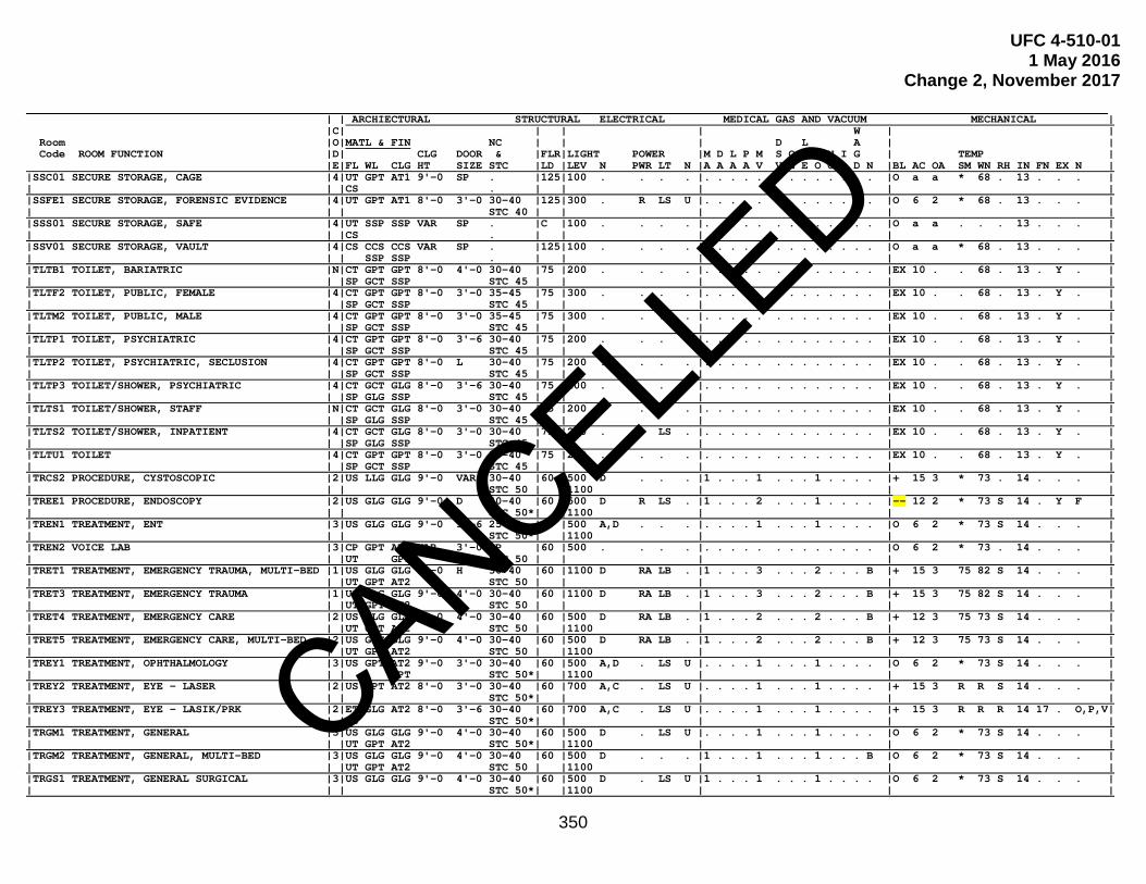
UFC 4-510-01 1 May 2016
Change 2, November 2017
350
. | | ARCHIECTURAL STRUCTURAL ELECTRICAL MEDICAL GAS AND VACUUM MECHANICAL | |C| | | | W | | Room |O|MATL & FIN NC | | | D L A | | Code ROOM FUNCTION |D| CLG DOOR & |FLR|LIGHT POWER |M D L P M S O D N I G | TEMP | |E|FL WL CLG HT SIZE STC |LD |LEV N PWR LT N |A A A A V V E E O O A D N |BL AC OA SM WN RH IN FN EX N | |SSC01 SECURE STORAGE, CAGE |4|UT GPT AT1 9'-0 SP . |125|100 . . . . |. . . . . . . . . . . . . |O a a * 68 . 13 . . . | | | |CS . | | | | | |SSFE1 SECURE STORAGE, FORENSIC EVIDENCE |4|UT GPT AT1 8'-0 3'-0 30-40 |125|300 . R LS U |. . . . . . . . . . . . . |O 6 2 * 68 . 13 . . . | | | | STC 40 | | | | | |SSS01 SECURE STORAGE, SAFE |4|UT SSP SSP VAR SP . |C |100 . . . . |. . . . . . . . . . . . . |O a a . . . 13 . . . | | | |CS . | | | | | |SSV01 SECURE STORAGE, VAULT |4|CS CCS CCS VAR SP . |125|100 . . . . |. . . . . . . . . . . . . |O a a * 68 . 13 . . . | | | | SSP SSP . | | | | | |TLTB1 TOILET, BARIATRIC |N|CT GPT GPT 8'-0 4'-0 30-40 |75 |200 . . . . |. . . . . . . . . . . . . |EX 10 . . 68 . 13 . Y . | | | |SP GCT SSP STC 45 | | | | | |TLTF2 TOILET, PUBLIC, FEMALE |4|CT GPT GPT 8'-0 3'-0 35-45 |75 |300 . . . . |. . . . . . . . . . . . . |EX 10 . . 68 . 13 . Y . | | | |SP GCT SSP STC 45 | | | | | |TLTM2 TOILET, PUBLIC, MALE |4|CT GPT GPT 8'-0 3'-0 35-45 |75 |300 . . . . |. . . . . . . . . . . . . |EX 10 . . 68 . 13 . Y . | | | |SP GCT SSP STC 45 | | | | | |TLTP1 TOILET, PSYCHIATRIC |4|CT GPT GPT 8'-0 3'-6 30-40 |75 |200 . . . . |. . . . . . . . . . . . . |EX 10 . . 68 . 13 . Y . | | | |SP GCT SSP STC 45 | | | | | |TLTP2 TOILET, PSYCHIATRIC, SECLUSION |4|CT GPT GPT 8'-0 L 30-40 |75 |200 . . . . |. . . . . . . . . . . . . |EX 10 . . 68 . 13 . Y . | | | |SP GCT SSP STC 45 | | | | | |TLTP3 TOILET/SHOWER, PSYCHIATRIC |4|CT GCT GLG 8'-0 3'-6 30-40 |75 |200 . . . . |. . . . . . . . . . . . . |EX 10 . . 68 . 13 . Y . | | | |SP GLG SSP STC 45 | | | | | |TLTS1 TOILET/SHOWER, STAFF |N|CT GCT GLG 8'-0 3'-0 30-40 |75 |200 . . . . |. . . . . . . . . . . . . |EX 10 . . 68 . 13 . Y . | | | |SP GLG SSP STC 45 | | | | | |TLTS2 TOILET/SHOWER, INPATIENT |4|CT GCT GLG 8'-0 3'-0 30-40 |75 |200 . . LS . |. . . . . . . . . . . . . |EX 10 . . 68 . 13 . Y . | | | |SP GLG SSP STC 45 | | | | | |TLTU1 TOILET |4|CT GPT GPT 8'-0 3'-0 30-40 |75 |200 . . . . |. . . . . . . . . . . . . |EX 10 . . 68 . 13 . Y . | | | |SP GCT SSP STC 45 | | | | | |TRCS2 PROCEDURE, CYSTOSCOPIC |2|US LLG GLG 9'-0 VAR 30-40 |60 |500 D . . . |1 . . . 1 . . . 1 . . . . |+ 15 3 * 73 . 14 . . . | | | | STC 50 | |1100 | | | |TREE1 PROCEDURE, ENDOSCOPY |2|US GLG GLG 9'-0 D 30-40 |60 |500 D R LS . |1 . . . 2 . . . 1 . . . . |-- 12 2 * 73 S 14 . Y F | | | | STC 50*| |1100 | | | |TREN1 TREATMENT, ENT |3|US GLG GLG 9'-0 3'-6 25-35 |60 |500 A,D . . . |. . . . 1 . . . 1 . . . . |O 6 2 * 73 S 14 . . . | | | | STC 50*| |1100 | | | |TREN2 VOICE LAB |3|CP GPT AT1 VAR 3'-0 SP |60 |500 . . . . |. . . . . . . . . . . . . |O 6 2 * 73 . 14 . . . | | | |UT GPT STC 50 | | | | | |TRET1 TREATMENT, EMERGENCY TRAUMA, MULTI-BED |1|US GLG GLG 9'-0 H 30-40 |60 |1100 D RA LB . |1 . . . 3 . . . 2 . . . B |+ 15 3 75 82 S 14 . . . | | | |UT GPT AT2 STC 50 | | | | | |TRET3 TREATMENT, EMERGENCY TRAUMA |1|US GLG GLG 9'-0 4'-0 30-40 |60 |1100 D RA LB . |1 . . . 3 . . . 2 . . . B |+ 15 3 75 82 S 14 . . . | | | |UT GPT AT2 STC 50 | | | | | |TRET4 TREATMENT, EMERGENCY CARE |2|US GLG GLG 9'-0 4'-0 30-40 |60 |500 D RA LB . |1 . . . 2 . . . 2 . . . B |+ 12 3 75 73 S 14 . . . | | | |UT GPT AT2 STC 50 | |1100 | | | |TRET5 TREATMENT, EMERGENCY CARE, MULTI-BED |2|US GLG GLG 9'-0 4'-0 30-40 |60 |500 D RA LB . |1 . . . 2 . . . 2 . . . B |+ 12 3 75 73 S 14 . . . | | | |UT GPT AT2 STC 50 | |1100 | | | |TREY1 TREATMENT, OPHTHALMOLOGY |3|US GPT AT2 9'-0 3'-0 30-40 |60 |500 A,D . LS U |. . . . 1 . . . 1 . . . . |O 6 2 * 73 S 14 . . . | | | | GPT STC 50*| |1100 | | | |TREY2 TREATMENT, EYE - LASER |2|US GPT AT2 8'-0 3'-0 30-40 |60 |700 A,C . LS U |. . . . 1 . . . 1 . . . . |+ 15 3 R R S 14 . . . | | | | STC 50*| | | | | |TREY3 TREATMENT, EYE - LASIK/PRK |2|ET GLG AT2 8'-0 3'-6 30-40 |60 |700 A,C . LS U |. . . . 1 . . . 1 . . . . |+ 15 3 R R R 14 17 . O,P,V| | | |US STC 50*| | | | | |TRGM1 TREATMENT, GENERAL |3|US GLG GLG 9'-0 4'-0 30-40 |60 |500 D . LS U |. . . . 1 . . . 1 . . . . |O 6 2 * 73 S 14 . . . | | | |UT GPT AT2 STC 50*| |1100 | | | |TRGM2 TREATMENT, GENERAL, MULTI-BED |3|US GLG GLG 9'-0 4'-0 30-40 |60 |500 D . . . |1 . . . 1 . . . 1 . . . B |O 6 2 * 73 S 14 . . . | | | |UT GPT AT2 STC 50 | |1100 | | | |TRGS1 TREATMENT, GENERAL SURGICAL |3|US GLG GLG 9'-0 4'-0 30-40 |60 |500 D . LS U |1 . . . 1 . . . 1 . . . . |O 6 2 * 73 S 14 . . . | | | | STC 50*| |1100 | | |
CANCELLED

UFC 4-510-01 1 May 2016
Change 2, November 2017
351
. | | ARCHIECTURAL STRUCTURAL ELECTRICAL MEDICAL GAS AND VACUUM MECHANICAL | |C| | | | W | | Room |O|MATL & FIN NC | | | D L A | | Code ROOM FUNCTION |D| CLG DOOR & |FLR|LIGHT POWER |M D L P M S O D N I G | TEMP | |E|FL WL CLG HT SIZE STC |LD |LEV N PWR LT N |A A A A V V E E O O A D N |BL AC OA SM WN RH IN FN EX N | |TRGS2 TREATMENT, GENERAL SURGICAL, |3|US GLG GLG 9'-0 4'-0 30-40 |60 |500 D . LS U |1 . . . 1 . . . 1 . . . . |-- 12 2 * 73 S 14 . Y . | | AIRBORNE INFECTION ISOLATION | | STC 50*| |1100 | | | |TRGS3 TREATMENT, GENERAL SURGICAL, LASER |3|US GLG GLG 9'-0 4'-0 30-40 |60 |500 A,D . LS U |1 . . . 1 . . . 1 . . . . |O 6 2 * 68 S 14 . . . | | | | STC 50*| |1100 | | | |TROB1 TREATMENT, OB/GYN |C|US GLG GLG 9'-0 4'-0 30-40 |60 |500 D . LS U |1 . . . 1 . . . 1 . . . . |O 6 2 * 73 S 14 . . . | | | | STC 50*| |1100 | | | |TROR1 PROCEDURE, ORTHOPAEDIC |3|US GLG GLG 9'-0 4'-0 30-40 |60 |500 D . LS U |1 . . . 1 . . . 1 . . . . |O 6 2 * 73 S 14 . . . | | | | STC 50*| |1100 | | | |TRPE1 PROCEDURE, PROCTOSCOPY (LGI) |2|US GLG GLG 9'-0 4'-0 30-40 |60 |500 D R LS . |1 . . . 2 . . . 1 . . . . |- 10 2 * 73 S 14 . Y . | | | | STC 50*| |1100 | | | |TRPE2 PROCEDURE, BRONCHOSCOPY |2|US GLG GLG 9'-0 4'-0 30-40 |60 |500 D R LS . |1 . . . 2 . . . 1 . . . . |-- 12 2 * 73 S 14 . Y . | | | | STC 50*| |1100 | | | |TRSP1 TREATMENT / RECOVERY, SUPPORT AREA | Space Parameter Notes: a | | | | |TUB01 TUB ROOM, PATIENT |3|CT GCT GLG 8'-0 4'-0 30-40 |C |200 . . LS . |. . . . . . . . . . . . . |EX 10 . . 68 . 13 . Y . | | | |SP GLG GPT STC 45 | | | | | |UCCL1 UTILITY, CLEAN |4|UT GPT AT1 8'-0 3'-6 30-40 |100|200 . . . . |. . . . . . . . . . . . . |+ 4 2 * 68 . 14 . . . | | | | STC 40 | | | | | |UCCL2 UTILITY, SCOPE WASH, CLEAN |4|US GPT AT1 8'-0 3'-0 30-40 |100|200 . . . . |. . . . . . . . . . . . . |+ 4 2 * 68 . 14 . . . | | | | STC 40 | | | | | |USCL1 UTILITY, SOILED |4|UT GLG AT1 8'-0 3'-0 30-40 |100|200 . . . . |. . . . . . . . . . . . . |- 10 2 * 68 . 13 . Y . | | | |US AT2 STC 40 | | | | | |USCL2 UTILITY, SCOPE WASH, SOILED |4|US GLG AT1 8'-0 3'-0 30-40 |100|500 . . . . |. . . . 1 . . . . . 1 . . |- 10 2 * 68 . 14 . Y M | | | | AT2 STC 40 | | | | | |USDD1 UTILITY, SOILED, DETERGENT DISPENSING |4|UT GLG AT1 8'-0 3'-0 30-40 |C |200 . . . . |. . . . . . . . . . . . . |- 10 2 * 68 . 13 . Y . | | | |US AT2 STC 40 | | | | | |UTC01 UTILITY, TRASH COLLECTION |4|CS GLG GLG 8'-0 3'-0 30-40 |125|200 . . . . |. . . . . . . . . . . . . |- 10 1 * 68 . 13 . Y . | | | | SSP SSP STC 40 | | | | | |UTC02 UTILITY, TRASH CAN DECON |4|CS CCS GLG 8'-0 3'-0 30-40 |B |50 . . . . |. . . . . . . . . . . . . |- 10 1 . . . 13 . Y . | | | | SSP SSP STC 40 | | | | | |UTLC1 UTILITY, TRASH AND LINEN COLLECTION |4|UT GLG GLG 8'-0 3'-0 30-40 |C |200 . . . . |. . . . . . . . . . . . . |- 10 1 * 68 . 13 . Y . | | | | SSP SSP STC 40 | | | | | |UTMW1 UTILITY, MEDICAL WASTE HOLDING |4|UT GLG AT1 8'-0 3'-6 30-40 |100|200 . . . . |. . . . . . . . . . . . . |- 10 2 * 68 . 13 . Y . | | | |US AT2 STC 40 | | | | | |UTR01 UTILITY, WASTE RECYCLING |4|UT GLG AT1 8'-0 3'-6 30-40 |125|200 . . . . |. . . . . . . . . . . . . |- 10 2 * 68 . 13 . Y . | | | |US AT2 STC 40 | | | | | |UTR02 UTILITY ROOM, WASTE PULPER SYSTEM |4|UT GLG AT1 8'-0 3'-0 30-40 |F |200 . . . . |. . . . . . . . . . . . . |- 10 2 * 68 . 13 . Y . | | | |US AT2 STC 40 | | | | | |VCSS1 VETERINARY, INSTRUMENT PREP |N|AR GEP AT2 9'-0 4'-0 30-40 |C |700 . . . . |. . . . 1 . . . . . 1 . . |- 10 2 * 68 . 14 . Y . | | | | GLG STC 50 | | | | | |VCWA1 VETERINARY, CAGE WASH |N|ER BEP AT2 9'-0 4'-0 30-40 |C |200 . . . . |. . . . . . . . . . . . . |- 10 1 * 68 . 13 . Y . | | | | GEP STC 50 | | | | | |VEX01 VETERINARY, EXAMINATION/TREATMENT |N|SR GEP AT2 9'-0 3'-0 30-40 |C |500 D R LB . |. . . . . . . . . . . . . |O 4 2 * 68 . 13 . Y . | | | | STC 50 | |1100 | | | |VEX02 VETERINARY, GENERAL TREATMENT |N|SR GEP AT2 9'-0 4'-0 30-40 |C |500 D R LB . |1 . . . 1 . . . . . . . . |- 4 2 * 68 . 13 . Y . | | | | STC 50 | |1100 | | | |VFIL1 VETERINARY, FOOD INSPECTION LAB |N|SR GEP AT2 9'-0 4'-0 30-40 |C |500 C . LS . |. . . . . . . . . . . . . |- 6 2 * 68 . 14 . Y M | | | | GPT STC 50 | |1100 | | | |VFP01 VETERINARY, FOOD PREP |N|SR GEP AT2 9'-0 4'-0 30-40 |C |500 . . LS . |. . . . . . . . . . . . . |+ 6 2 * 68 . 14 . Y . | | | | STC 50 | | | | | |VHAU1 VETERINARY, HOLDING AREA UTILITY/STR |N|ER BEP AT2 9'-0 4'-0 30-40 |C |150 . . . . |. . . . . . . . . . . . . |- 6 2 * 68 . 13 . Y . | | | | GEP GPT STC 50 | | | | | |VKAR1 VETERINARY, KENNEL CONFINE, ANTE-ROOM |N|ER GEP GEP 9'-0 4'-0 30-40 |C |100 . . . . |. . . . . . . . . . . . . |- 10 5 * 68 . 13 . Y L | | | | STC 50 | |300 | | |
CANCELLED

UFC 4-510-01 1 May 2016
Change 2, November 2017
352
. | | ARCHIECTURAL STRUCTURAL ELECTRICAL MEDICAL GAS AND VACUUM MECHANICAL | |C| | | | W | | Room |O|MATL & FIN NC | | | D L A | | Code ROOM FUNCTION |D| CLG DOOR & |FLR|LIGHT POWER |M D L P M S O D N I G | TEMP | |E|FL WL CLG HT SIZE STC |LD |LEV N PWR LT N |A A A A V V E E O O A D N |BL AC OA SM WN RH IN FN EX N | |VKEN1 VETERINARY, KENNEL AREA IN/OUTSIDE |N|ER BEP AT2 9'-0 4'-0 30-40 |C |100 . . . . |. . . . . . . . . . . . . |- 10 5 * 68 . 13 . Y L | | | | GEP GEP STC 50 | |300 | | | |VKEN2 VETERINARY, KENNEL CONFINE CANINE |N|ER BEP AT2 9'-0 4'-0 30-40 |C |100 . . . . |. . . . . . . . . . . . . |- 10 5 * 68 . 13 . Y L | | | | GEP GPT STC 50 | |300 | | | |VKEN3 VETERINARY, KENNEL CONFINE FELINE |N|ER BEP AT2 9'-0 4'-0 30-40 |C |100 . . . . |. . . . . . . . . . . . . |- 10 5 * 79 . 13 . Y L | | | | GEP GPT STC 50 | |300 | | | |VLAH1 VETERINARY, LARGE ANIMAL HOLDING |N|ER BEP AT2 9'-0 VET 30-40 |C |100 . . LS . |. . . . . . . . . . . . . |- 10 5 * 79 . 13 . Y L | | | | GEP GPT STC 50 | |300 | | | |VLB01 VETERINARY, LABORATORY |N|AR GEP GEP 9'-0 4'-0 30-40 |C |500 C . LB . |. . . . . . . . . . . . . |- 6 2 * 68 . 13 . . M | | | | STC 40 | |1100 | | | |VLBF1 VETERINARY, LAB, FOOD INSPECTION |N|AR GEP GEP 9'-0 4'-0 30-40 |C |500 C . LB . |. . . . . . . . . . . . . |- 6 2 * 68 . 13 . Y . | | | | STC 40 | |1100 | | | |VLBF2 VETERINARY, LAB, FOOD TESTING |N|AR GEP AT2 9'-0 4'-0 30-40 |C |500 C . LB . |. . . . . . . . . . . . . |- 6 2 * 68 . 13 . Y . | | | | GLG STC 40 | |1100 | | | |VNEC1 VETERINARY, NECROPSY |N|ER GEP GEP 9'-0 4'-0 30-40 |C |700 D . . . | . . . 1 . . . . . 1 . . |- 12 3 R R . 13 . Y M | | | | STC 40 | |1600 | | | |VPH01 VETERINARY, PHARMACY |N|ER GEP GEP 9'-0 4'-0 30-40 |C |1100 . R L . |. . . . . . . . . . . . . |+ 4 2 * 68 . 13 . . . | | | | STC 40 | | | | | |VRHA1 VETERINARY, RODENT HOLDING |N|ER BEP GEP 9'-0 VET 30-40 |C |100 . R LS . |. . . . . . . . . . . . . |- 15 15 * 79 . 13 . Y . | | | | STC 50 | |300 | | | |VRIC1 VETERINARY, RECOVERY, INTENSIVE CARE |N|ER GEP AT2 9'-0 4'-0 30-40 |C |500 . . . . |1 . . . 1 . . . 1 . . . . |+ 6 3 * 68 . 13 . Y L | | | | GLG STC 50 | | | | | |VRRP1 VETERINARY, RECOVERY ROOM/PREP |N|SR GEP AT1 9'-0 4'-0 30-40 |C |500 . RA LB . |1 . . . 1 . . . 1 . . . . |+ 6 3 64 79 . 13 . Y . | | | | STC 40 | | | | | |VRUN1 VETERINARY, ANIMAL RUN |N|ER BEP GEP 9'-0 4'-0 30-40 |C |100 . . . . |. . . . . . . . . . . . . |O 6 3 * 68 . 13 . Y L | | | | STC 40 | | | | | |VS001 VETERINARY, SURGERY |N|ER GEP GEP 9'-0 4'-0 30-40 |C |2100 D RA LB . |1 . . . 2 . . . 1 . . . . |+ 15 7.5 64 79 . 13 14 Y C | | | | STC 40 | | | | | |VSPD1 VETERINARY, SURGERY, PREP / DENTAL |N|ER GEP GEP 9'-0 4'-0 30-40 |C |500 D R LB . |1 1 . . 1 1 . . . . 1 . . |+ 6 2 64 79 . 13 . Y . | | | | STC 40 | |1100 | | | |VSSG1 VETERINARY, SURGERY, SCRUB / GOWN |N|ER GEP GEP 9'-0 N 30-40 |C |1100 C . LB . |. . . . . . . . . . . . . |+ 6 2 75 75 . 14 . . . | | | | STC 40 | | | | | |VXER1 VETERINARY, XRAY EXPOSURE |N|ER LEP GEP 9'-6 4'-0 30-40 |C |500 I . . . |. . . . . . . . . . . . . |O 4 2 * 68 . 13 . Y . | | | | STC 40 | | | | | |VXER2 VETERINARY, ULTRASOUND |N|AR GEP AT2 9'-0 VET 30-40 |C |300 . . . . |1 . . . 1 . . . . . . . . |O 4 2 * 68 . 13 . Y . | | | | GLG STC 50 | |500 | | | |WKTM1 WORKROOM, TEAM, RESIDENT |4|UT GPT AT1 8'-0 3'-0 30-40 |60 |500 . . L . |. . . . . . . . . . . . . |O 4 1 * 70 . 13 . . . | | | |CP STC 40 | | | | | |WRC01 WAITING |4|SP GPT AT1 9'-0 3'-0 35-45 |100|300 . . . . |. . . . . . . . . . . . . |O 6 1 * 68 . 14 . . S | | | |UT STC 50*| | | | | |WRC02 WAITING, ISOLATION |4|US GLG GLG 9'-0 3'-0 35-45 |100|300 . . . . |. . . . . . . . . . . . . |-- 12 2 * 68 . 13 . Y Q | | (INCLUDES EMERGENCY AND PEDIATRICS) | | GPT GPT STC 50*| | | | | |WRC03 SUB-WAITING |4|SP GPT AT1 9'-0 3'-0 35-45 |100|300 . . . . |. . . . . . . . . . . . . |O 6 1 * 68 . 14 . . S | | | |UT STC 50*| | | | | |WRCH1 TEAM COLLABORATION |4|UT GPT AT1 8'-0 3'-0 30-40 |60 |500 . . . . |. . . . . . . . . . . . . |O 4 1 * 70 . 13 . . . | | | |CP STC 40 | | | | | |WRF01 FAMILY RESPITE |4|CP GPT AT1 9'-0 3'-0 35-45 |60 |300 . . . . |. . . . . . . . . . . . . |O 6 1 * 68 . 14 . . S | | | |UT GPT STC 50*| | | | | |WRL01 LITTER, PATIENT STAGING |4|UT GPT AT1 9'-0 3'-6 35-45 |60 |300 . . . . |. . . . . . . . . . . . . |O 4 1 * 70 . 14 . . . | | | | STC 50*| | | | | |WRTM2 TELEHEALTH |3|UT GPT AT1 8'-0 3'-0 30-40 |60 |500 A,C . . . |. . . . . . . . . . . . . |O 6 2 * 73 . 14 . . . | | | | STC 50*| | | | | |XABP1 XRAY, ANGIOGRAPHIC, PROCEDURE |1|US LLG AT1 10'-0 4'-0 30-40 |100|500 D,I . . U |1 . . . 2 . . . 1 . . . . |O 6 2 * 73 . 14 . . . | | | |UT LPT GPT STC 40 | | | | |
CANCELLED

UFC 4-510-01 1 May 2016
Change 2, November 2017
353
. | | ARCHIECTURAL STRUCTURAL ELECTRICAL MEDICAL GAS AND VACUUM MECHANICAL | |C| | | | W | | Room |O|MATL & FIN NC | | | D L A | | Code ROOM FUNCTION |D| CLG DOOR & |FLR|LIGHT POWER |M D L P M S O D N I G | TEMP | |E|FL WL CLG HT SIZE STC |LD |LEV N PWR LT N |A A A A V V E E O O A D N |BL AC OA SM WN RH IN FN EX N | |XACR1 XRAY, ANGIOGRAPHIC, CONTROL |4|US GLG AT1 8'-0 3'-0 30-40 |100|300 . . . U |. . . . . . . . . . . . . |O 6 2 * 70 . 13 . . . | | | |UT GPT GPT STC 40 | | | | | |XACV1 XRAY, ANGIOGRAPHIC, SYSTEM COMPONENT |4|US GLG AT1 8'-0 3'-0 30-40 |100|300 . . . U |. . . . . . . . . . . . . |O 6 2 * 70 . 13 . . N | | | |UT GPT STC 40 | | | | | |XAIR1 XRAY, ANGIOGRAPHIC, INSTRUMENT |4|US GLG AT1 8'-0 3'-0 30-40 |100|300 . . . U |. . . . . . . . . . . . . |O 6 2 * 70 . 13 . . . | | | |UT GPT STC 40 | | | | | |XCCA1 XRAY, CARDIAC, SYSTEM COMPONENT |4|US GLG AT1 8'-0 3'-0 30-40 |100|500 . RA LB . |. . . . . . . . . . . . . |O 4 2 68 75 . 14 . . N | | | |UT GPT STC 40 | | | | | |XCCC1 XRAY, CARDIAC CATH, CONTROL |4|US GLG AT1 8'-0 3'-0 30-40 |100|300 A R L . |. . . . . . . . . . . . . |O 4 2 68 75 . 14 . . N | | | |UT GPT STC 40 | | | | | |XCCE1 XRAY, CARDIAC CATH, PROCEDURE |1|US LLG AT1 10'-0 4'-0 30-40 |100|300 A R L . |1 . . . 2 . . . 3 1 . 1 . |+ 15 3 75 73 . 14 . . C | | | |UT LPT GPT STC 40 | | | | | |XCCI1 XRAY, CARDIAC CATH, INSTRUMENT |4|US GLG AT1 8'-0 3'-0 30-40 |100|300 . . LS . |. . . . . . . . . . . . . |+ 6 2 68 75 . 14 . . . | | | |UT GPT STC 40 | | | | | |XCTC1 XRAY, COMPUTED TOMOGRAPHY, CONTROL |4|US GLG AT1 8'-0 3'-0 30-40 |100|300 A . . U |. . . . . . . . . . . . . |O 6 2 * 70 . 13 . . . | | | |UT GPT STC 40 | | | | | |XCTC2 XRAY, COMPUTED TOMOGRAPHY, COMPONENT |4|US GLG AT1 8'-0 4'-0 30-40 |C |300 . . . U |. . . . . . . . . . . . . |O 4 2 * 68 . 13 . . N | | | |UT GPT STC 40 | | | | | |XCTI1 XRAY, COMPUTED TOMOGRAPHY, INDEP VIEW |4|US GLG AT1 8'-0 3'-0 30-40 |100|300 A . . U |. . . . . . . . . . . . . |O 4 2 * 70 . 13 . . N | | CONSOLE | |UT GPT STC 40 | | | | | |XCTS1 XRAY, COMPUTED TOMOGRAPHY, SCANNER |C|US LLG AT1 VAR 4'-0 30-40 |100|500 D,I . . U |. . . . 1 . . . 1 . . . . |O 6 2 * 73 . 14 . . . | | | |UT LPT GPT STC 40 | | | | | |XDBD1 XRAY, BONE DENSITOMETER |3|US GLG AT1 9'-0 4'-0 30-40 |100|500 . . . U |. . . . . . . . . . . . . |O 6 2 * 73 . 14 . . . | | | |UT GLG GPT STC 40 | | | | | |XDCS1 XRAY, CHEST |3|US LLG AT1 10'-0 4'-0 30-40 |100|500 A,C . . U |. . . . . . . . . . . . . |O 6 2 * 73 . 14 . . . | | | |UT LPT GPT STC 40 | | | | | |XDCY1 XRAY, CYSTOLOGY/RADIOLOGY |2|US LLG AT1 10'-0 4'-0 30-40 |100|500 D,I RA LB . |1 . . . 3 . . . 1 . . . D |O 6 2 * 73 . 14 . . . | | | |UT LPT GPT STC 40 | | | | | |XDM01 XRAY, MAMMO |3|US LLG AT1 9'-0 4'-0 30-40 |100|500 A,C . LS U |. . . . . . . . . . . . . |O 4 2 * 73 . 14 . . . | | | |UT LPT GPT STC 40 | | | | | |XDM02 XRAY, MAMMO, STEREOTATIC |2|US LLG AT1 9'-0 4'-0 30-40 |100|500 A,C . LS U |. . . . 1 . . . 1 . . . . |O 6 2 * 73 . 14 . . . | | | |UT LPT STC 40 | | | | | |XDMP1 XRAY, MAMMO, PROCESS |4|US GLG AT1 8'-0 3'-0 30-40 |100|500 A,C . . U |. . . . . . . . . . . . . |- 10 2.5 * 73 . 14 . Y M | | | |UT GPT GPT STC 40 | | | | | |XDR01 XRAY, RADIOGRAPHIC, GENERAL |3|UT LLG AT1 9'-6 4'-0 30-40 |100|500 C,I . . U |. . . . . . . . . . . . . |O 6 2 * 73 . 14 . . . | | | | LPT STC 40 | | | | | |XDRF1 XRAY, RAD/FLUORO |C|UT LLG AT1 9'-6 4'-0 30-40 |100|500 C,I . . U |. . . . . . . . . . . . . |O 6 2 * 73 . 14 . . . | | | | LPT STC 40 | | | | | |XDUS1 XRAY, ULTRASOUND |3|UT GPT AT1 8'-0 4'-0 30-40 |100|500 A,C . . U |. . . . 1 . . . 1 . . . . |O 6 2 * 73 . 14 . . . | | | | GLG STC 45 | | | | | |XFDS1 XRAY, STORAGE, DIGITAL FILES |4|UT GPT AT1 8'-0 3'-0 30-40 |100|300 . . . U |. . . . . . . . . . . . . |+ 6 1 * 68 . 13 . . N | | | | STC 40 | | | | | |XFFA1 XRAY, STORAGE, FILM FILES, FIXED |4|UT GPT AT1 VAR 3'-0 30-40 |250|300 . . . . |. . . . . . . . . . . . . |O 4 2 * 68 . 13 . . . | | SHELVES | | STC 40 | | | | | |XFFA2 XRAY, STORAGE, FILM FILES, MOBILE |4|UT GPT AT1 VAR 3'-0 30-40 |350|300 . . . . |. . . . . . . . . . . . . |O 4 2 * 68 . 13 . . . | | SHELVES | | STC 40 | | | | | |XMRC1 XRAY, MAGNETIC RESONANCE, CONTROL |4|UT GLG AT1 8'-0 3'-0 30-40 |100|300 A . . U |. . . . . . . . . . . . . |O 4 2 * 68 . 13 . . . | | | |US GPT STC 40 | | | | | |XMRC2 XRAY, MAGNETIC RESONANCE, SYSTEM |4|UT GLG AT1 8'-0 4'-0 30-40 |100|300 . . . U |. . . . . . . . . . . . . |O 4 2 * 68 . 13 . . N | | COMPONENT | |US GPT STC 40 | | | | | |XMRE1 XRAY, MAGNETIC RESONANCE, EQUIPMENT |4|UT GLG AT1 8'-0 4'-0 30-40 |100|300 . . . U |. . . . . . . . . . . . . |O 4 2 * 68 . 13 . . . | | | |US GPT STC 40 | | | | | |XMRF1 XRAY, MAGNETIC RESONANCE, |4|UT GLG AT1 8'-0 4'-0 30-40 |100|300 . R . U |. . . . . . . . . . . . . |O 4 2 * 68 . 13 . . . | | FERROMAGNETIC DETECTION | |US GPT STC 40 | | | | |
CANCELLED

UFC 4-510-01 1 May 2016
Change 2, November 2017
354
. | | ARCHIECTURAL STRUCTURAL ELECTRICAL MEDICAL GAS AND VACUUM MECHANICAL | |C| | | | W | | Room |O|MATL & FIN NC | | | D L A | | Code ROOM FUNCTION |D| CLG DOOR & |FLR|LIGHT POWER |M D L P M S O D N I G | TEMP | |E|FL WL CLG HT SIZE STC |LD |LEV N PWR LT N |A A A A V V E E O O A D N |BL AC OA SM WN RH IN FN EX N | |XMRS1 XRAY, MAGNETIC RESONANCE, SCANNER |3|UT GLG AT1 VAR 4'-0 30-40 |C |300 C,I . . U |1 . . . 1 . . . 1 1 . 1 . |O 6 2 * 73 . 14 . . . | | | |US GPT STC 50 | | | | | |XMRV1 XRAY, MAGNETIC RESONANCE, VIEWING |4|UT GLG AT1 8'-0 3'-0 30-40 |100|300 . . . U |. . . . . . . . . . . . . |O 4 2 * 68 . 13 . . . | | | |US GPT STC 40 | | | | | |XPCC1 XRAY, SPECT / PET / CT CONTROL |4|US GLG AT1 8'-0 3'-0 30-40 |100|300 A R . U |. . . . . . . . . . . . . |O 4 2 * 70 . 13 . . N | | | |UT GPT STC 40 | | | | | |XPCC2 XRAY, SPECT / PET / CT COMPONENT |4|US GLG AT1 8'-0 4'-0 30-40 |100|300 A . . U |. . . . . . . . . . . . . |O 6 2 * 70 . 13 . . N | | | |UT GPT STC 40 | | | | | |XRM01 XRAY, STORAGE, MOBILE RAD UNIT |4|UT GPT AT1 8'-0 L 30-40 |100|150 . . . E |. . . . . . . . . . . . . |O . . . . . 13 . . . | | | |US GPT STC 40 | | | | | |XTBC1 XRAY, BRACHYTHERAPY, CONTROL |4|US GLG AT1 8'-0 3'-0 30-40 |E |300 A R . U |. . . . . . . . . . . . . |O 4 2 * 70 . 13 . . N | | | |UT GPT STC 40 | | | | | |XTBT1 XRAY, BRACHYTHERAPY |2|UT GLG AT1 8'-6 4'-0 30-40 |100|700 A,C . LB U |1 . . . 1 . . . 1 . . . . |+ 6 2 * 70 . 14 . Y . | | | |US GPT STC 40 | | | | | |XTEM1 XRAY, THERAPY, ENTRY MAZE |4|US GLG AT1 10'-0 SP 30-40 |C |200 . . LS . |. . . . . . . . . . . . . |O 6 2 * 68 . 13 . . . | | | |UT GPT STC 40 | | | | | |XTLA1 XRAY, THERAPY, LINEAR ACCELERATOR |3|US GLG AT1 10'-0 4'-0 30-40 |C |500 D,I . LB . |. . . . 1 . . . 1 . . . . |O 6 2 * 73 . 14 . Y . | | | |UT GPT STC 40 | | | | | |XTLA2 XRAY, THERAPY, LINEAR ACCELERATOR, |3|US GLG AT1 10'-0 4'-0 30-40 |C |500 D,I . LB . |. . . . 1 . . . 1 . . . . |O 6 2 * 73 . 14 . Y . | | HIGH VOLTAGE | |UT GPT STC 40 | | | | | |XTLA3 XRAY, THERAPY, LINEAR ACCELERATOR, |3|US GLG AT1 10'-0 4'-0 30-40 |C |500 D,I . LB . |. . . . 1 . . . 1 . . . . |O 6 2 * 73 . 14 . Y . | | DUAL VOLTAGE | |UT GPT STC 40 | | | | | |XTLB1 XRAY, THERAPY, PHYSICS LABORATORY |4|US GLG AT1 9'-0 3'-0 30-40 |100|500 C . . . |. . . . . . . . . . . . . |- 6 2 * 70 . 13 . . . | | | |UT GPT STC 40 | |1100 | | | |XTLC1 XRAY, THERAPY, LINEAR ACCELERATOR, |4|US GLG AT1 8'-0 4'-0 30-40 |100|300 A . . . |. . . . . . . . . . . . . |O 6 2 * 68 . 13 . . . | | CONTROL | |UT GPT STC 40 | | | | | |XTLE1 XRAY, THERAPY, LINEAR ACCELERATOR, |4|US GLG AT1 VAR 3'-0 30-40 |100|500 A,C . LB U |. . . . . . . . . . . . . |O 4 2 * 68 . 14 . . N | | SYSTEM COMPONENT | |UT GPT STC 40 | | | | | |XTMF1 XRAY, THERAPY, MOLD FABRICATION SHOP |4|US GLG AT1 9'-0 3'-0 30-40 |100|500 . . . . |. . . . . . . . . . . . . |- 6 2 * 68 . 13 . Y M | | | |UT GPT STC 40 | | | | | |XTRT1 XRAY, THERAPY, RADIUM TX STORAGE/PREP |4|US LLG AT1 8'-0 3'-0 30-40 |100|500 C . . . |. . . . . . . . . . . . . |- 6 2 * 68 . 13 . Y M | | | |UT LPT STC 40 | |1100 | | | |XTSC1 XRAY, THERAPY, SIMULATOR CONTROL |4|US GLG AT1 8'-0 3'-0 30-40 |100|300 A . LB . |. . . . . . . . . . . . . |O 6 2 * 68 . 13 . . . | | | |UT GPT STC 40 | | | | | |XTSC2 XRAY, THERAPY, SIMULATOR, SYSTEM |4|US GLG AT1 8'-0 4'-0 30-40 |C |300 A . . U |. . . . . . . . . . . . . |O 4 2 * 68 . 13 . . N | | COMPONENT | |UT GPT STC 40 | | | | | |XTSG1 XRAY, THERAPY, SIMULATOR GANTRY |4|US GLG AT1 10'-0 4'-0 30-40 |100|300 . . . . |. . . . 1 . . . 1 . . . . |O 6 2 * 70 . 13 . . . | | | |UT GPT STC 40 | | | | | |XTSM1 X-RAY, THERAPY, SIMULATOR, MAGNETIC |4|UT GLG AT1 VAR 4'-0 30-40 |E |300 C,I . . . |1 . . . 1 . . . 1 1 . 1 . |O 6 2 * 73 . 14 . . . | | RESONANCE | |US GPT STC 50 | | | | | |XTTP1 XRAY, THERAPY, TREATMENT PLANNING |4|UT GLG AT1 8'-0 3'-0 30-40 |100|500 . . . . |. . . . . . . . . . . . . |O 6 2 * 70 . 13 . . . | | | |US GPT STC 40 | | | | | |XVC01 XRAY, VIEWING/CONSULTATION |4|UT GPT AT1 8'-0 3'-0 30-40 |60 |300 A . LS U |. . . . . . . . . . . . . |O 4 1 * 68 . 13 . . . | | | |US GLG STC 40 | | | | |
CANCELLED

UFC 4-510-01 1 May 2016
Change 2, November 2017
355
APPENDIX C DESIGN SUBMITTALS AND DOCUMENTATION
C-1 GENERAL.
This Appendix addresses narratives, drawings, calculations, and cost estimates required at various submission levels during the production of construction contract documents for each project.
C-2 APPLICATION.
The submission requirements in this Appendix identify minimum information that must be provided under each submission level. The Design and Construction Agent shall develop additional specific submission requirements as required.
C-3 GENERAL REQUIREMENTS.
These general requirements apply to all projects and submittal requirements.
C-3.1 Narratives and Format.
Narratives shall describe architectural and engineering design features of a project across all disciplines. The narrative portion of all submittals, to include written descriptions, calculations, cost estimates, specifications, and equipment lists, shall be packaged in standard U.S. three-ring binders with labeled subject dividers, sequential page numbers, and table of contents. Date and properly identify all documents according to project title and level of submission. Project title shall exactly reflect that which is noted on the enacted DD Form 1391.
C-3.2 Drawings and Format.
Drawing format and submissions shall be as required by the Design and Construction Agent and the following.
C-3.2.1 Building Information Modeling (BIM).
Reference Chapter 20 Building Information Modeling (BIM), for specific execution. Compact disc submissions shall include, at a minimum, BIM, CAD, and PDF files.
C-3.2.2 Perspective Drawing Sketch and Final Rendering.
C-3.2.1.1 Perspective Drawing Sketch.
The perspective drawing sketch shall best depict the proposed facility and its prominent design features as directed by the Design and Construction Agent. This sketch shall be the basis for subsequent rendering requirements.
CANCELLED

UFC 4-510-01 1 May 2016
Change 2, November 2017
356
C-3.2.1.2 Rendering.
A final rendering shall be prepared from the perspective drawing sketch that reflects all review comments. A color photograph of the final rendering, approximately 20 inches by 16 inches, shall be sent to DHA/FD by the Design and Construction Agent. The photograph shall be titled, single matted, framed, and glazed with non-glare tempered glass or plexiglass. The frame shall be 28 inches by 20 inches in dimension and of a brushed aluminum finish. Other photographs shall be distributed as determined by the Design and Construction Agent.
C-3.3 Building Systems Risk Assessment.
Not later than the 20 percent design (DBB process) submission, the A/E shall conduct a risk assessment to confirm or establish the Building System Category for each of the various facility systems in accordance with NFPA 99. For the DB process, the assessment shall be conducted by the A/E, and included as part of the RFP development. In all cases, the assessment shall be fully coordinated with the Using Military Department and Design and Construction Agent to carefully consider and document system requirements necessary to adequately safeguard occupant safety, health, and comfort, based on the intended CONOPS and acuity of the patient population to be served by that facility.
C-4 5 PERCENT SUBMITTAL.
The submittal shall document the outcome of the 5 percent meeting. The following shall be presented at the 5 percent meeting:
C-4.1 5 Percent Submittal Narratives.
The narratives include pros and cons of presented block plans, preliminary site information, and architectural, transportation, and engineering considerations. Provide an Executive Summary of the 5 Percent Report, documenting the selected solution to be further developed to 20 percent design.
C-4.2 5 Percent Submittal Drawings.
C-4.2.1 Site Plans.
The A/E shall develop and present alternative site plans, supporting the three block plan proposals. For each site plan, show the following:
a. Site Master Plan of each alternative to include location and orientation of all new building structures. Include existing structures (note whether they are to remain or be considered for demolition).
b. Antiterrorism standoff distances. c. Desirable site views, natural weather conditions, e.g., wind/sand storms
and seasonal sun orientation d. Existing site topography that may impact building development.
CANCELLED

UFC 4-510-01 1 May 2016
Change 2, November 2017
357
e. Major utility connection locations (points of origin). f. On- and offsite vehicular and service traffic patterns to include primary
and secondary roadways surrounding the site. g. Parking recommendations (surface or structured). h. Future building expansion (maximum 20 percent of the enacted DD Form
1391 gross building area [in gross square feet (GSF)]); include future parking structure locations as applicable.
i. Site noise/sound generating conditions, e.g., proximity to major highway, adjacency to an airport.
j. Optional location or methodology to incorporate the VA or other organization’s program, if applicable.
C-4.2.2 Block Plans.
Up to three block plans shall be developed to convey the project requirements. Each block plan shall show floor to floor and departmental relationships; exterior elevation views; location of vertical and horizontal transportation systems, e.g., elevators, escalators, and stairs; circulation patterns and movement of material, supplies, and people; and impacts to corridor widths due to transportation solutions or other unique conditions, e.g., AGVs, IBS, or similar systems. In addition, provide principal key dimensions. One block plan, most representing the defined requirements, shall be selected for further development under the 20 percent submittal.
C-4.2.3 Addition/Alteration Projects.
Clearly delineate where existing conditions end and new conditions begin. Clearly define the extent and scope of renovations and alterations. This includes all associated work in these areas; not only finishes and upgrades, but also utility runs such a new ductwork and IT support.
C-4.3 5 Percent Submittal Cost Estimates.
C-4.3.1 Parametric Cost Estimates.
Provide a parametric cost estimate for each block plan developed.
C-5 20 PERCENT SUBMITTAL.
This submittal includes development of the room-by-room floor plans, building elevations, and preliminary analysis of major architectural and engineering systems based on the selected block plan. It identifies and resolves all major PFD changes, solidifies all space requirements, such as departmental or mission realignment, and ensures the designed scope complies with the authorized scope at an early stage in design development. Refinements to the building massing and aesthetics of the facility, e.g., building’s character, proposed exterior material finishes, and other specific architectural and engineering building features; determination of O&M access for primary MEP, and communication equipment, including primary distribution pathways;
CANCELLED

UFC 4-510-01 1 May 2016
Change 2, November 2017
358
determine stormwater management strategy to meet the requirements of EISA; and establishment of the cost and scope of providing necessary utility services to and from the building are included. Further improvements of the site plan are required to coordinate major building entrances to parking and pedestrian paths of travel. For addition/alteration projects, this submittal shall also establish preliminary phasing considerations and scope impact. The MTLC shall also present at the 20 percent design meetings describing how the facility design addresses the transportation, logistics, and waste management requirements of the facility.
C-5.1 Scope Changes.
Requests for scope changes shall be submitted by the Using Military Department to DHA/FD with the 20 percent submittal. Scope changes are defined as those that materially affect the characteristics of the facilities (e.g. Category Code) or increase the GSF as defined in Block 8 of the DD1391. Refer to Chapter 3. Develop a clear justification and basis for any increases to the GSF, e.g., mission changes, workload increases, and increases in troop numbers due to troop or unit reassignments.
C-5.2 Record Copy.
The Design and Construction Agent shall submit a record copy of the 20 percent submittal to DHA/FD. No approval from DHA/FD is required at the 20 percent submittal. However, a presentation to DHA/FD shall be required if the project has exceeded the authorized scope or over budget.
C-5.3 20 Percent Design Narratives.
The following are minimum 20 percent submittal design narratives describing proposed architectural and engineering aspects of the project: List all criteria, codes and standards that the project shall adhere to.
C-5.3.1 Executive Summary.
The executive summary shall include this narrative information:
a. Rationale for the selected block plan scheme; b. Proposed architectural and engineering systems; c. Approach to sustainable design, energy reduction, \2\/2/and other related
energy compliant features to the project; d. Designed scope and budget compared to the authorized scope and
budget; e. Specific military base requirements impacting the design of the project,
e.g., building exterior finishes, excessive noise factors, and other site/building constraints; and
f. Utility services available and their points of entry into the project’s site, including privatized utilities and their impact on scope and cost to the project.
CANCELLED
UFC 4-510-01 1 May 2016
Change 2, November 2017
359
C-5.3.2 World-Class Checklist.
A World-Class Checklist shall be developed for every project providing direct patient care and shall include all architectural and engineering disciplines. It shall be applied across the entire life of a project, from conception to recapitalization, and apply to additions, renovations, and restoration of a facility. For addition/renovation projects, refer to the original project’s World-Class Checklist and documentation to ensure these standards are maintained and continued. When a World-Class Checklist exists for a particular project, create an addendum to that World-Class Checklist for all addition/renovation projects providing direct care to the patient.
C-5.3.3 Civil.
Refine the 5 percent submittal site investigation and utilities report. Discuss approach to Stormwater Management and “Low Impact Development”.
C-5.3.4 Architectural.
Address the overall architectural concept including: exterior wall systems and finish materials, acoustics, base architectural plan, floor-to-floor heights, roofing materials, slope(s), styles, energy conservation features, sustainable design, commissioning, life safety, and fire protection. Describe how proposed material selections and finishes shall support aseptic environments, infection control and patient/staff safety.
C-5.3.5 Interstitial Building System (IBS).
If approved, the narrative shall address IBS to include its design, documentation, and technical requirements in accordance with Appendix E, Interstitial Building System.
C-5.3.6 Structural.
Discuss and describe the justification and basis for the proposed system.
C-5.3.7 Seismic.
Discuss the seismic design considerations and the level of protection required. Evaluate the seismic impacts to the structural design system being proposed for new facilities. For addition/alteration projects, provide a preliminary Facility Upgrade Report that includes a Seismic Structural Assessment and Evaluation Study.
C-5.3.8 Heating, Ventilation, and Air Conditioning (HVAC).
Discuss design considerations and space requirements for the primary and secondary HVAC systems being considered and how they compare based on Life Cycle cost Analysis. Also, explain how the design shall provide weather-protection; direct floor-to-ground access for equipment O&M, e.g., pallet transport via hydraulic hand carts; and practical means of future replacement.
CANCELLED

UFC 4-510-01 1 May 2016
Change 2, November 2017
360
C-5.3.9 Plumbing.
Discuss design considerations and space requirements for the various plumbing systems to include: domestic hot and cold water, e.g., water supply, quality, hot water generation, storage requirements, temperatures; and distribution systems, fuel gas, medical gases (types, storage, and distribution systems), sanitary waste and vent, and storm drains. Address compliance with post-seismic storage and water conservation criteria and regulations, if applicable.
C-5.3.10 Electrical.
Address design considerations and space requirements for electrical systems. In particular, discuss: voltage, routing, and reliability of primary services; connected and demand load; normal and essential electrical systems; emergency power; lighting systems; and energy conservation features. Include in the discussion earthquake impacts to normal and alternate power, and vulnerability to the electrical distribution system, switches, and other features serviced by these power systems.
C-5.3.11 Communications.
Discuss design considerations and space requirements for all communications systems required for the project.
C-5.3.12 Fire Protection.
Address the fire detection, alarm, and suppression systems and features for the facility.
Life Safety. Address the type of construction, fire rating of materials, and occupancy classification for the facility. For addition/alteration projects, provide an LSA Report. Reference paragraph 8-6.1, Life Safety Assessment.
C-5.3.13 Physical Security.
Discuss the physical security system design, consideration, parameters, major features, and space requirements for the overall facility and specialized areas such as those processing classified or sensitive information. Refer to APPENDIX H for requirements for Behavioral Health.
C-5.3.14 Antiterrorism/Force Protection (AT/FP).
Discuss site, design, and any space considerations and requirements for AT/FP systems. Include confirmation of the Installation’s concurrence and approval of the plan, if required by the Installation.
C-5.3.15 Sustainability\2\/2/ and Energy Conservation Compliance.
Discuss status toward meeting project goals, known and potential \2\sustainable rating system/2/ points, and initial calculated energy costs and energy consumption status relative to the ANSI/ASHRAE 90.1 baseline. This narrative shall include separate sections for Architecture, Site, Mechanical, and Electrical. Include proposed checklist.
CANCELLED

UFC 4-510-01 1 May 2016
Change 2, November 2017
361
C-5.3.16 Commissioning.
A preliminary Commissioning Plan shall be developed and submitted that defines the method by which commissioning shall be performed. The Commissioning Plan shall outline and define its process to include commissioned systems, participants, roles and responsibilities, communication procedures, and deliverables. Discuss procedures for achieving required commissioning of all commissioned systems. Reference Chapter 21, Commissioning, for additional information.
C-5.3.17 Transportation and Logistics.
Provide a preliminary, overall Transportation and Logistics Study shall be provided that discusses the rational for the proposed transportation, logistics, waste management, and food service solutions to include impacts to programmed scope and cost. The Study shall include: (1) an Elevator Traffic Analysis and Study, (2) an LCCA for automatic and manual material handling systems, (3) a Waste Management Study, and (4) a Food Service Study, as applicable. The Waste Management Study shall include the major design parameters and features that address trash removal; hazardous, infectious, and biological waste; retort sterilizers; incinerators; and other waste handling features of the design. See Chapter 17, Transportation and Logistics, and Appendix F, Food Service, for additional requirements regarding these studies. In addition, address and discuss PTSs, as well as dumbwaiters and AGV systems.
C-5.3.18 Wayfinding.
A preliminary wayfinding master plan shall be provided that addresses necessary orientation cues and information for patients, staff, and visitors to navigate in and around a facility. Identify environmental paths, edges, regions, nodes, and landmarks used to successfully move from one destination to another. Analyze a facility’s spatial organization and layout to identify specific areas, directional challenges, and wayfinding tools that can help in navigation. Consider all types of functions and activities a person must perform when in a Military Medical Facility. Reference \2\Chapter 4, Architectural/2/, for further requirements in developing a wayfinding master plan.
C-5.3.19 Food Service.
If applicable, discuss the food service design and considerations to include optimal movement of food products to ensure effective monitoring and control of food temperatures through conventional flow while minimizing personnel cross-traffic, backtracking, and queuing conditions.
C-5.3.20 Equipment List.
Update the equipment list provided by the Using Military Department for all logistical categories of equipment. Key this list to each room identified on the floor plans.
CANCELLED

UFC 4-510-01 1 May 2016
Change 2, November 2017
362
C-5.3.21 Construction Phasing.
As required by the Design and Construction Agent, develop a written narrative of the overall requirements for a phased approach to the construction that addresses all work associated with all the major disciplines. Develop a preliminary construction phasing plan that addressees “major” areas of work that require specific parameters, sequence, or milestones. This phasing plan is not a typical technical sequence of normal construction work, but describes any situation that would prevent the contractor from doing all areas of the work simultaneously or at his discretion. Preliminary identification of phased areas and durations should be identified with reference to scope, constructability, timing, and overall construction length. Requirements unique to phased projects such as swing space, utilities that shall have to serve two areas simultaneously, demolition sequence, and engineering system support for isolated or independent areas, shall be addressed in reference to the operational, constructability, and cost constraints of the project.
Addition/Alteration Projects. For addition/alteration projects, develop and discuss a preliminary construction phasing plan that supports continued/uninterrupted operations of the existing facility during construction and associated impact on construction costs and scope. Identify the requirements for temporary buildings to serve as swing space. In addition, identify actions that reduce or interrupt service to an existing, occupied area. Identify potential temporary connections, extensions of service that increase system demand, locations of new connections, or other measures necessary to sustain service for engineering systems within the existing building.
C-5.4 20 Percent Submittal Design Drawings.
The following are minimum 20 percent submittal drawings depicting proposed architectural and engineering aspects of the project:
C-5.4.1 Architectural Drawings.
Provide floor plans for each floor showing all programmed spaces and corridors; key building dimensions; structural grid system (including columns and type of system proposed) and key building dimensions; electrical and mechanical equipment rooms; stairs, elevators, and escalators; transportation equipment for movement of material and supplies; and specific locations of vertical and horizontal transportation systems, e.g., pneumatic tubes, dumb waiters, automated guidance systems, elevators, escalators, and stairs. All spaces identified in the PFD shall be labeled with the Room Name and Room Code, in addition to the programmed and designed net areas. Also, addition/alteration projects shall include preliminary demolition drawings with photographs depicting existing conditions. Provide preliminary exterior elevations with proposed finishes.
C-5.4.2 Interstitial Building System (IBS).
If approved for project, a preliminary IBS design shall be developed, e.g., plans and sections, that delineates interdisciplinary cross-sections at critical locations.
CANCELLED

UFC 4-510-01 1 May 2016
Change 2, November 2017
363
C-5.4.3 HVAC, Plumbing, and Electrical Plans.
Provide plans showing single line drawings of the distribution systems of major MEP, and communications from these spaces to the areas served. MEP space designs shall be based on estimates of equipment capacity and building demand.
C-5.4.4 Food Service Plans.
If applicable, provide plans showing an initial layout of all applicable food service areas. Show circulation paths from servers to seating, loading dock to storage, kitchen to inpatient units, general material movement, principal dimensions, and dining seating counts. Optimize movement of food products and minimize personnel cross-traffic, backtracking, and queuing conditions. Reference Appendix F, Food Service, for additional requirements.
C-5.4.5 Construction Phasing Plan.
As required by the Design and Construction Agent, provide a graphic “Node” diagram of major elements and areas showing proposed sequential and parallel phased work. Indicate interim swing space, temporary facilities and locations of existing and relocated functions.
C-5.4.6 Addition/Alteration Projects.
For addition/alteration projects, update and continue to differentiate where existing conditions end and new conditions begin. Define extent and scope of renovations. Provide documentation of existing conditions.
a. Existing building as-builts. b. Statement of conditions. c. Existing/Prior hazardous material abatement reports and studies
C-5.5 20 Percent Submittal Calculations.
C-5.5.1 A/E Calculations.
All calculations that support A/E features within the design shall be provided. Supporting documentation shall include life cycle cost analysis (LCCA) for energy/renewable systems, LED lighting, solar hot water use, and utility demand. Documentation should also include validation of the parking requirements.
C-5.5.2 Gross/Net Area Tabulations.
Gross and net area tabulations for all floors, along with a small-scale, single-line, dimensioned key plan, shall be provided to reflect the total space required per Chapter 3, Design. Provide an area summary comparing the as-designed areas (net areas, departmental gross areas, minimum grossing ratios, and building gross area) with the PFD values.
CANCELLED

UFC 4-510-01 1 May 2016
Change 2, November 2017
364
C-5.6 20 Percent Submittal Cost Estimates.
Provide schematic cost estimates reflecting all design features and elements. Update all project costs based on refined project design details. Provide an updated DD Form 1391. Show PCAS and “Other” special cost as separate line items.
C-6 35 PERCENT SUBMITTAL
This submittal is a minimum 35 percent of the total design across all disciplines and incorporates response to all review comments. This is considered the “technical submission” in which all major A/E design decisions are finalized along with project scope and costs. Thus, load demand, equipment sizing, energy consumption, LCC, life safety, and other calculations for all building systems and features defined herein shall be required. Provide a Physicist Report for all radiation areas. Additional submission requirements shall be defined by the Design and Construction Agent. The 35 percent design shall be reviewed by the Design and Construction Agent and Using Military Department; at the same time, the 35 percent design shall also be submitted to DHA/FD. A formal presentation shall be required of this submission; A/E participation may be requested on large or complex projects. DHA/FD shall provide review comments for the 35 percent design within 14 days of the formal presentation along with approval, approval with exceptions or comments, or disapproval with explanation. Final changes to the project’s enacted DD Form 1391 description, justification, and execution timelines are made at this submittal level. The following are the minimum requirements for the 35 percent design submittal:
C-6.1 35 Percent Submittal Design Narratives.
Concept design narratives describing further refinement of the 20 percent design requirements to a 35 percent design effort shall be provided as noted here:
C-6.1.1 World-Class Checklist.
Update the draft World-Class Checklist, and briefly discuss the merits of each element identified in the World-Class Checklist, to include specific solutions that shall be developed during the project’s design. As applicable, also list other alternative solutions considered under each element. Indicate elements excluded from the draft World-Class Checklist, and explain why they are excluded from the project design.
C-6.1.2 Civil.
Include the site investigation and utilities reports. Summarize the civil design parameters, parking, and major features of the design.
C-6.1.3 Architectural.
Address the overall architectural concept including interior (in accordance with Appendix B, Architectural and Engineering Design Requirements) and exterior finish materials, wall systems, roofing systems, acoustics, base architectural plan, floor-to-floor heights, and contingency and mobilization features. Provide a final functional narrative that
CANCELLED

UFC 4-510-01 1 May 2016
Change 2, November 2017
365
describes alignment of the design with the design CONOPS developed for the project. See the CONOPS sections of Chapter 1, Introduction, Chapter 2, Planning, and Chapter 3, Design. Describe how proposed material selections and finishes shall promote aseptic environments and infection control and patient/staff safety.
C-6.1.4 Interstitial Building System (IBS).
If approved, update the design parameters and major features, including interstitial space considerations.
C-6.1.5 Structural.
Address the selected structural foundation and framing systems considered and provide an economic basis for system selection. Summarize the structural design parameters and major features of the design.
C-6.1.6 Seismic.
Summarize the seismic design considerations including “S” values and the level of protection required. Discuss post-earthquake operation requirements. For alteration and repair projects, complete the Facility Upgrade Report.
C-6.1.7 HVAC.
Provide a summary of the primary and secondary HVAC systems considered and the economic basis for system selection. Summarize the proposed control systems, fire protection features, and the energy conservation features being considered.
C-6.1.8 Plumbing.
Describe the various plumbing systems to include domestic hot and cold water, fuel gas, sanitary waste and vent, and storm drains. Summarize the water supply, quality, required storage, and distribution systems. Discuss hot water generation, storage, temperatures, and distribution systems. Address various types of medical gases, storage, and distribution systems.
C-6.1.9 Electrical.
Summarize the electrical design parameters and the major features of the design. Address voltage, routing, and reliability of primary services; connected and demand load; normal/essential/emergency electrical systems; lighting systems; and energy conservation features.
C-6.1.10 Communication.
Summarize all communication system design parameters and major features.
CANCELLED

UFC 4-510-01 1 May 2016
Change 2, November 2017
366
C-6.1.11 Fire Protection.
Summarize the fire protection system design parameters and major features to include: fire detection, alarm, and suppression systems. For addition/alteration projects, provide a summary of the analysis of the FSES Study. Include related design considerations and criteria that have been coordinated among all the affected disciplines.
Life Safety. Summarize the life safety considerations, design parameters, and major features. Address type of construction, fire rating of materials, life safety features, and occupancy classification. For addition/alteration projects, provide a summary of the analysis of the latest LSA Report.
C-6.1.12 Physical Security.
Summarize the security system design parameters and major features.
C-6.1.13 Antiterrorism/Force Protection (AT/FP).
Summarize the AT/FP system design parameters and major features.
C-6.1.14 Sustainability\2\/2/ and Energy Performance/Conservation Compliance.
Identify status toward reaching \2\sustainable/2/ certification by providing a matrix listing and briefly describing achievable and potential “points” with economic impact. Identify energy cost reduction and energy conservation compliance relative to ANSI/ASHRAE 90.1 baseline. Discuss all energy conservation design features considered and those to be implemented. Confirm energy budget compliance and energy conservation features.
C-6.1.15 Commissioning.
Summarize the Commissioning Plan and process to achieve the required commissioning of all commissioned systems. Include the final Commissioning Plan incorporating comments received. Further clarify the process by which commissioning shall be performed.
C-6.1.16 Transportation and Logistics.
Summarize the recommendations and analyses (pros and cons), rational, and scope and cost impacts of the overall Transportation and Logistics Study to include all sub-studies, e.g., Elevator Traffic Analysis and Study, Life-Cycle Cost Analysis for automatic and manual material handling systems, a Waste Management Study, and a Food Service Study (include all food serve areas). The MTLC shall also present at the 35 percent design meetings describing how the facility design addresses the transportation, logistics, and waste management requirements of the facility. The Transportation and Logistics Study shall be completed at the 35 percent submission.
C-6.1.17 Wayfinding.
Summarize the wayfinding master plan recommendations, solutions, and tools for patients, staff, and visitors to navigate in and around a facility. Identify any scope and
CANCELLED

UFC 4-510-01 1 May 2016
Change 2, November 2017
367
cost impacts to proposed recommendations, solutions, and tools. Summarize the types of functions and activities a person may perform in a Military Medical Facility.
C-6.1.18 Food Service.
If applicable, summarize the food service design. Discuss its parameters and major features to include optimal movement of food products to all designated locations; minimal cross-traffic, backtracking, and queuing conditions; and separation of personnel traffic.
C-6.1.19 Equipment Specifications.
C-6.1.19.1 Equipment List. The A/E shall further refine the initial equipment list into a viable Military Medical Facility room contents list or room-by-room listing. Coordinate all categories of equipment for each room identified on the list as well as substitutions or changes with the Using Military Department. The type, quantity, and location of biological, radioisotope, fume, canopy, and laminar air hoods shall also be indicated in the equipment list. Provide appropriate equipment data and catalog cut sheet(s) for all items of equipment having unique utility requirements, structural support, or space requirements.
C-6.1.19.2 Develop requirements for all equipment that does not have current information, as directed by the Design and Construction Agent.
C-6.1.20 Outline Specifications.
Provide outline specifications.
C-6.1.21 Construction Phasing.
A written narrative shall be provided, developed, and documented by the A/E that shows one overall workable phasing plan. This phasing plan shall indicate proposed construction duration and describe major elements of the work and any impacts on or by the Government. The phasing plan shall include the scope and timing sequence of each identifiable phase or major activity with required precedents, procurement, Government move durations, commissioning, and outfitting. Each phase shall be described in terms of the work involved and what work has to come before and after the phase. Phasing elements affecting the Government but not the contractor, such as Government only actions, should be determined and documented.
Addition/Alteration. For addition/alteration projects, further identify work activities in a phasing plan that would impact any requirements for continued operation of a facility, including temporary utilities, swing space, implementation of hygienic barriers, and temporary access routing.
C-6.2 35 Percent Submittal Design Drawings.
35 percent submittal design drawings describing further refinement of the 20 percent design requirements to a 35 percent design effort shall be provided as noted here:
CANCELLED

UFC 4-510-01 1 May 2016
Change 2, November 2017
368
C-6.2.1 World-Class Checklist.
Graphically locate all draft World-Class Checklist elements to be provided in specific project documents, i.e., for typical plans, elevations, sections, and details, across all architectural and engineering disciplines.
C-6.2.2 Civil (Site).
Show building location, future expansion, existing and proposed structures, topography, final master plan of the site, utilities (include point of origin), utility modifications, roads, parking (surface and structured), and landscaping.
C-6.2.3 Architectural.
C-6.2.3.1 Floor. For each floor, show all programmed spaces; corridors; structural grid systems (including columns); electrical/communications/mechanical equipment rooms; all vertical and horizontal transportation, e.g., stairs, elevators, escalators, pneumatic tubes, dumbwaiters; and AGV to meet functional requirements and CONOPS for the building. All spaces identified in the PFD shall be labeled with the Room Name and Room Code. Provide programmed and designed net area tabulations. Provide key building dimensions.
C-6.2.3.2 Reflected Ceiling. Show ceiling grid and light fixture placement.
C-6.2.3.3 Exterior Elevations and Major Building Sections. Include all exterior views and multiple cross sections through all unique building areas.
C-6.2.4 Interstitial Building System (IBS).
If approved for project, a conceptual IBS design shall be developed, e.g., plans and sections, and that delineates interdisciplinary cross-sections at critical locations.
C-6.2.5 Structural.
Provide drawings of the selected structural system adequately developed so no additional major engineering decisions are required.
C-6.2.6 HVAC.
Show layout of mechanical rooms with all major equipment and one line drawing of distribution systems. Footprints of air handling and other major equipment shall be established from catalog dimensional data of three manufacturers. Include clearance space for component cleaning, removal, and maintenance. Distribution mains shall be dimensioned. If integral sound attenuating devices are required in VAV/CAV terminal units, indicate these on the project design documents for the respective terminal unit(s).
C-6.2.7 Plumbing.
Show plumbing, medical air, vacuum, medical gas equipment, and major distribution lines. Water supply and gravity drainage mains shall be dimensioned. Design all
CANCELLED

UFC 4-510-01 1 May 2016
Change 2, November 2017
369
aspects of the piping systems to control thermal expansion and distribution. In the design drawings, include all necessary control features such as location of guides, anchors, expansion ells, offsets, flexible couplings, and other piping features that may affect expansion forces in the piping. For steam and condensate piping, show the required direction, degree of line slope, details of drip traps, and other drainage features.
C-6.2.8 Electrical.
Show placement and location of electrical room layouts, light fixtures, receptacles, motor controls, panelboards, and distribution equipment. Provide single line diagrams of the normal/essential electrical systems, emergency power, and uninterruptable power supply (UPS). Include NFPA 99 risk analysis for wet procedure locations in accordance with Chapter 11, Electrical. Include the grounding system design and initial testing requirements in the project design documents.
C-6.2.9 Communication.
Show layout of communication equipment, devices, and closets. Provide single line diagrams for each system. Develop, in detail, a Zone Light Activation Matrix (including identification numbers) that shall be detailed on the telecommunication systems project design documents. A matrix shall be developed for each patient care unit served.
C-6.2.10 Physical Security.
If ESSs are included in the project design, these systems shall be detailed in the project design documents. Include information such as sensor locations, floor plans, riser diagrams, security equipment schedules, monitoring and control equipment, alarm control panels, switches, and access control devices.
C-6.2.11 Fire Protection.
Show sprinklered areas, fire pumps, stand pipes, fire extinguisher cabinets, and fire alarm systems. Coordinate all design features with applicable criteria and all architecture and engineering disciplines.
C-6.2.12 Life Safety.
Show sprinklered areas, fire-rated walls and doors, smoke compartments, fire extinguisher cabinets, and fire exits. Show the occupancy classifications and maximum travel distances to smoke and fire barriers.
C-6.2.13 Wayfinding.
Graphically indicate specific wayfinding locations, proposed solutions, and tools that relates to each of the facility’s paths, edges, regions, nodes, and landmarks.
CANCELLED

UFC 4-510-01 1 May 2016
Change 2, November 2017
370
C-6.2.14 Food Service.
Food service equipment items shall be identified in detail in the project design documents and represent the latest available technology. Specific equipment locations, utility requirements including ventilation, and equipment installation shall also be shown. Include mounting heights for all wall-hung equipment items.
C-6.2.15 Equipment (to include FFE).
Show all Categories of equipment. Show construction contract equipment on the equipment drawings and floor plans with solid lines and Government and all other furnished equipment with dashed lines. Provide JSNs as indicated in the PRC for all applicable logistical categories. Indicate and properly detail the type, quantity, and location of biological, radioisotope, fume, canopy, and laminar air hoods on the drawings. Coordinate all equipment locations and details to ensure adequate utility requirements, structural support, or space requirements are provided.
C-6.2.16 Structural Interior Design (SID).
Provide a 35 percent SID package. The SID package shall be fully coordinated with all interior and exterior finishes, colors, and materials. Key the room finishes schedule to the plans by room number and name. Include proposed SID color scheme/selections. Provide color boards with samples of major finishes or pictures thereof. An aseptic environment Infection Control Risk Assessment shall be coordinated with the SID package to define infection control risks associated within each project. (Reference Chapter 4 Architectural, paragraph 4-5.1 for additional details.) The wayfinding plan shall also be an integral part of the facility’s SID package and enhance the design features. The Infection Control Risk Assessment and the wayfinding plan are critical to begin early in the design process. See Glossary for expanded definitions of the SID.
C-6.2.17 Comprehensive Interior Design (CID)
Provide a 35 percent CID package for furniture and accessory selection. The CID package shall be fully coordinated with all finishes, colors, and materials included in the SID package. Provide description and cut sheets for all CID items. Include specific artwork selections. (Reference Chapter 4 Architectural, paragraph 4-5.1 for additional details.) See Glossary for expanded definitions of the CID.
C-6.2.18 Construction Phasing.
Provide a graphic “node” diagram (not a bar chart or time-scaled bar chart) to show the relationships established in the phasing narrative. The graphic representation of the phasing plan in the contract documents should not indicate durations (numerical or graphical) except for the contractually established durations such as Owner moves. Individual phase durations should be considered only in developing the Government’s proposed overall contract duration. This phasing plan should not be confused with the requirement to determine the overall constructability and construction timeline that may involve a more detailed milestone chart. The phasing should be coordinated and documented in the design drawings either as a segregated set with all engineering
CANCELLED

UFC 4-510-01 1 May 2016
Change 2, November 2017
371
disciplines addressed or have associated drawings within each discipline. A separate overall phasing plan shall be developed for the Government’s use only to inform, educate, and track Government actions. It should include interaction of Government activities such as move times, swing space durations, and Government outfitting and training activities. This plan shall further delineate the coordination of required actions of the Government that are not a part of the contractor’s responsibility or contract.
Addition/Alteration Projects. For addition/alteration projects, provide 35 percent demolition drawings indicating removal of structural, architectural, MEP, communications systems, and asbestos and other hazardous materials.
C-6.3 35 Percent Submittal Calculations.
C-6.3.1 Calculations.
Provide conceptual level calculations for all engineering systems being proposed.
C-6.3.2 Gross and Net Area Tabulations.
Update all gross and net area tabulations based on refined floor plans.
C-6.3.3 Sustainability\2\/2/ and Energy Performance/Conservation Compliance.
Provide all supporting calculations.
C-6.4 35 Percent Submittal Cost Estimates.
C-6.4.1 Cost Estimate.
Update all project costs. Align all revised costs in accordance with the DD Form 1391 format. Provide any changes to the project’s DD Form 1391 description, justification, and execution timelines.
C-6.4.2 Energy Performance/Conservation Compliance.
Identify energy cost reduction and energy conservation compliance relative to the ANSI/ASHRAE 90.1 baseline. Include return on investment cost calculations and LCC analyses that address all features.
C-7 65 PERCENT DESIGN SUBMITTAL.
The Design and Construction Agent shall develop the specific submittal requirements to define this level of effort. The project design documents shall reflect, at a minimum, a 65 percent level of coordination across all architecture and engineering disciplines and previous submittal requirements. Specifications should include a preliminary Division 01.
CANCELLED

UFC 4-510-01 1 May 2016
Change 2, November 2017
372
C-8 100 PERCENT AND FINAL DESIGN SUBMITTAL.
The Design and Construction Agent shall develop the specific submittal requirements to define this level of effort. When the design is complete, the Design and Construction Agent shall submit a copy of the final documents, e.g., drawings, specifications, cost estimate, instructions to bidders, to DHA/FD. These documents shall be fully coordinated across all architecture and engineering disciplines. In addition, the final World-Class Checklist and all supporting documentation shall be submitted to DHA/FD and the Using Military Department within 30 days of completing the 100 percent design documents. This information shall be used by facility managers to continue supporting world-class initiatives during construction, transition, outfitting, and O&M of the facility.
C-9 STATEMENT OF CONDITIONS (SOC).
If required by the Design and Construction Agent, a completed SOC shall be provided at the conclusion of construction by the designer of record.
C-10 REQUEST FOR PROPOSAL (RFP) FOR DESIGN-BUILD (DB) PROJECTS.
The RFP shall clearly define all the requirements and background information that a DB contractor shall need to estimate, bid, design, and construct the project. These requirements shall be included in the RFP as appropriate to the project:
a. Project Technical Requirements b. Updated DD Form 1391 c. Program for Design (PFD) d. Medical Concept of Operations (CONOPS) for the facility e. Project Room Contents (PRC) f. Requirements for:
• Comprehensive Interior Design (CID) • Structural Interior Design (SID)
g. Additional requirements as determined by the Design and Construction Agent to facilitate fast track construction.
C-11 RFP DEVELOPMENT SUBMITTALS.
These submittals are required during the RFP development:
a. 5 Percent Level Design Report b. Draft RFP (RFP Development). If 20 percent design is provided, include
all required submittals in paragraph C-5.3. c. Final RFP (RFP Development). If 35 percent design is provided, include
all required submittals in paragraph C-6.1.
CANCELLED

UFC 4-510-01 1 May 2016
Change 2, November 2017
373
C-12 AFTER CONTRACT AWARD.
Following the successful selection of a DB contractor and award of a DB contract, the DB contractor shall provide these comprehensive submittals to include, but not limited to, the following as previously defined:
a. Final 35 Percent Design Submittal b. 65 Percent Design Submittal c. 100 Percent Design Submittal
CANCELLED

UFC 4-510-01 1 May 2016
Change 2, November 2017
374
APPENDIX D UNIVERSAL X-RAY ROOM
D-1 DEFINITION.
The Universal X-ray Room is capable of accepting radiographic and fluoroscopic equipment, regardless of manufacturer, with minimal facility modification.
D-1.1 Applications.
The Universal X-ray Room applies to Appendix B, Architectural and Engineering Design Requirements, Room Codes XDR01 and XDRF1 (reference Figures D-1, D-2 and D-3). The A/E shall select an X-ray system for a basis of design based on the JSN provided in the PRC. The designer shall design this room to accommodate the selected system and the criteria listed here.
D-2 CRITERIA.
D-2.1 Electrical Raceway System.
The Electrical Raceway System includes a floor trench, wall ducts, and ceiling cable trays that meet the criteria listed here and additional requirements of the X-ray system selected as a basis of design for installation (reference Figures D-1, D-2 and D-3). All raceways and cable trays shall be UL-listed for enclosure of wiring to all X-ray system components and concealed in floors and walls or above the ceiling.
D-2.1.1 Floor Trench.
Floor trench shall be bottom-type trench duct, with nominal 3.5-inch by 12-inch duct and a 12-inch-wide by 1/4-inch-thick steel cover plate. Cover plate shall be installed flush with the floor with the same tile insert as the floor. Provide a gasket on the cover plate to maintain water tightness. Location of floor trench to the radiology table shall be determined by the X-ray system selected for the basis of design.
D-2.1.2 Core Drilling.
Provide oversized conduits below the floor deck in lieu of floor trench when the Universal E-Ray Room is located on a floor other that ground level.
D-2.1.3 Wall Ducts.
Wall ducts are nominal 3.5-inch by 10-inch with 12-inch-wide flush-mounted cover plates finished to match the walls. Transition wall ducts to the floor trench or the conduit below the floor deck.
D-2.1.4 Ceiling Cable Trays.
Ceiling cable trays are nominal 3.5-inch by 12-inch with 3-inch load depth National Electrical Manufacturers Association (NEMA) Class 12A ladder type installed above the finished ceiling.
CANCELLED

UFC 4-510-01 1 May 2016
Change 2, November 2017
375
D-2.1.5 Partition Separation.
Partitions shall be provided to separate high- and low-voltage cables in all trenches, ducts, and cable trays.
D-2.2 Electrical Service Requirements.
Each Universal X-ray Room shall have adequate power service to ensure the X-ray system can be installed without additional facility-related electrical work. All feeder conductors shall be copper.
D-2.2.1 Power Quality.
The facility power system shall provide the specified nominal voltage (480 V) +/-5 percent to each Universal X-ray Room. Special power conditioning equipment, if required, shall be identified and provided with the X-ray system installation.
D-2.2.2 X-Ray Equipment Service.
Provide 150 ampere, 480Y/277 V, 3-phase (5-wire, neutral, and ground) service to the room. Provide an adjustable trip, 150 ampere, 3-pole, shunt trip circuit breaker in a NEMA 1, flush-mounted enclosure.
D-2.2.3 Emergency Shutdown.
Provide a large, clearly identified push button to actuate the shunt trip circuit breaker to disconnect all power to the X-ray system.
D-2.2.4 Auxiliary Panelboard.
Provide a 120/208 V, single-phase, 100 A panelboard with a 50 A shunt trip main breaker to support the single-phase loads in each room. Provide a 20-pole-space panelboard with at least two 20 A, 2-pole circuit breakers, and five 20 A, 1-pole circuit breakers. This panelboard may be served from the nearest general-purpose 120/208 V transformer, or a dedicated step-down transformer fed from the 480 V service to the room. Calculations shall be based on 180 A maximum demand if fed from the 480 V service to the room.
D-2.2.5 Voltage Drop and Regulation.
Total voltage drop in a branch circuit and feeder conductors shall not exceed 2 percent from the facility distribution transformer to the Universal X-ray Room. Total voltage regulation of the distribution transformer, feeder, and branch circuit conductors shall not exceed 5 percent. For circuits that serve only one room, this calculation shall be based on the maximum demand current of the single X-ray generator. For circuits that serve more than one room, this calculation shall be based on the maximum demand current of the two largest rooms. Calculations shall be based on 180 A minimum demand. Wiring shall be sized for maximum 1 percent impedance.
CANCELLED

UFC 4-510-01 1 May 2016
Change 2, November 2017
376
D-2.2.6 Distribution Transformers.
Distribution transformers shall not be dedicated solely to the X-ray system. Voltage regulation is better when an X-ray system is connected to a transformer that is partially loaded with other equipment. X-ray systems shall always be connected line-to-line, never line-to-neutral.
D-2.2.7 Essential Power.
Essential power for X-ray systems, illumination, and duplex receptacles shall be in accordance with the Using Military Department guidance documents.
D-2.3 Warning Lights.
Provide “X-ray In-Use” warning light outside and above patient entry door. The “X-ray In-Use” light shall be controlled by the X-ray system control console. Conduit and wiring from the “X-ray in Use” light to the X-ray unit control console shall be provided.
D-2.4 D-2.4 Structural Requirements.
D-2.4.1 Walls.
Provide studs on either side of the vertical electrical raceways. Design walls to support 220 pounds vertical-to-horizontal pull. Double walls shall be provided between adjacent X-ray rooms. Wall backing and support is required for wall bucky units and control panels.
D-2.4.2 Ceiling Support System.
Provide an overhead tube-mount support system with a load-bearing capacity of 900 pounds vertical point load and 50 pounds per square foot uniformly distributed load. Ceiling support system to cover the complete ceiling area of the room. Spanning members shall be mounted perpendicular to the centerline of the X-ray table and positioned at 25-5/8 inches on center to provide 2 feet of clearance between members. The acoustical ceiling tiles shall be suspended from the spanning members. Bottom of spanning members shall be flush with the finished ceiling.
D-2.4.3 Floors.
When a floor trench is utilized, provide appropriately thickened slat to accommodate the floor trench.
D-2.5 Radiology Shielding.
D-2.5.1 At a minimum:
a. Radiation shielding shall be designed by a health physicist to ensure that the required degree of protection is achieved in compliance with NCRP Report No. 147. Certify in accordance with NCRP Report No. 102 and the Using Military Department qualified expert.
CANCELLED

UFC 4-510-01 1 May 2016
Change 2, November 2017
377
b. Lead shielding shall be 1/16 inch lead or lead equivalent up to 7 feet above the finished floor. Avoid penetrations through the shielding.
c. Lead shielding shall be applied to the Universal X-ray Room side of the wall partitions and laminated behind gypsum board for protection.
CANCELLED

UFC 4-510-01 1 May 2016
Change 2, November 2017
378
D-2.5.2 Use built-in or modular shielding for Operator’s Booth.
D-2.5.3 All ductwork, grilles, registers, and diffusers shall be located above or flush with the ceiling. Thermostat transmission lines shall be routed to avoid penetration of shielding.
D-2.6 Fire Protection.
D-2.6.1 Automatic sprinkler heads shall be recessed.
Figure D-1 Floor Plan
CANCELLED

UFC 4-510-01 1 May 2016
Change 2, November 2017
379
Figure D-2 Above Ceiling Plan
CANCELLED

UFC 4-510-01 1 May 2016
Change 2, November 2017
380
Figure D-3 Elevations
CANCELLED

UFC 4-510-01 1 May 2016
Change 2, November 2017
381
APPENDIX E INTERSTITIAL BUILDING SYSTEM (IBS)
E-1 GENERAL.
This Appendix provides criteria and guidance for the use and application of IBS concepts, including interstitial utility spaces.
E-2 IBS DESIGN CONCEPT.
The primary concept of interstitial spaces located between functional floor spaces is a non-traditional design feature that permits locating the majority of facility utility distribution and terminal equipment within the interstitial space, and not within functional spaces. This IBS concept offers the DoD several advantages over standard building design in providing convenient installation, maximizing utility access and maintainability, providing for future building flexibility, while minimizing disruption to medical or laboratory services.
E-2.1 DoD Systems Module Concept.
The fundamental approach to interstitial building design in DoD is the DoD Systems Module. The DoD Systems Module organizes building areas into discrete modules, normally defined by major medical department or occupancy boundary, and limited to 22,500 square feet in area. Each module is served by equipment, e.g., mechanical, electrical, and piping, located in a dedicated utility pod, from which the services are distributed within the confines of the module boundaries via a dedicated distribution zone (interstitial space) and connection zone (above-ceiling space) to the occupied zone (functional space) associated with the respective module. (Refer to Figure E-1.) Having dedicated services for each module, the user has full knowledge of the areas affected by O&M services and by future system modifications. The DoD Systems Module concept also results in greater standardization of major MEP equipment (such as AHUs), reducing the storage of spare parts, and increasing the overall dependability of the systems.
CANCELLED

UFC 4-510-01 1 May 2016
Change 2, November 2017
382
Figure E-1 DoD IBS Systems Module (Typical)
E-2.2 Alternate Non-Modular Concept.
An alternative, non-modular approach, also with interstitial floors for utility distribution, may in some cases be utilized for some types of DoD facilities. In some instances, the DoD Systems Module design concept can be less economical than a non-modular approach, and is not ideally suited for all building types, e.g., laboratories, in all locations. The non-modular designs typically differ from the DoD Systems Module in permitting equipment, such as AHUs, to serve different (multiple) functional areas, occupancies, or compartments. This can involve horizontal service distribution to differing parts of the building.
E-2.3 IBS Design Concept Approval.
For any IBS design, most requirements in this Appendix including those for construction of the interstitial floor (walk-on platform), utility penetrations, and the organization of the distribution zone for accessibility and fire safety must be incorporated into the design. The decision as to whether an IBS building shall follow the DoD Systems Module concept or an alternate non-modular design shall be evaluated following the 5 percent design submission and completed by the 20 percent submission by an economic comparison with alternatives. All costs associated with acquisition, operation, maintenance, and alteration for the designated service life of the proposed facility shall be included in the comparison. (Reference Appendix C, Design Submittals and Documentation, for submission requirements.)
CANCELLED

UFC 4-510-01 1 May 2016
Change 2, November 2017
383
E-3 IBS DESIGN.
E-3.1 DoD Systems Module Design.
The DoD Systems Module, a designated unit of space one story in height, is the basic building block of a DoD Systems Module facility, i.e., the facility is composed of separately identifiable DoD Systems Modules each consisting of a utility pod, a distribution zone, a connection zone, and an occupied zone. Each DoD Systems Module is served by its own utility distribution systems. The relationship of the various zones is illustrated in Figures E-1 and E-2. DoD Systems Modules shall not exceed 22,500 square feet, exclusive of the utility pod. Although there is a spatial discipline associated with the DoD Systems Module, the overall organization and massing of a facility can be varied according to specific project requirements.
E-3.1.1 Utility Pod.
The utility pod contains AHUs and associated risers, fans, pumps, and other related equipment; electrical and heat exchange equipment; and associated risers serving the DoD Systems Module. Fresh air and exhaust openings are generally part of the utility pod enclosure. The utility pod is the space between two adjacent structural floors or between the highest structural floor and the roof. In multi-story buildings, the utility pods shall be stacked from floor to floor so that plumbing and electrical risers can be efficiently and economically accommodated.
E-3.1.2 Distribution Zone.
The distribution zone is the space between the walk-on platform and the structural floor or roof above. The maximum height of the distribution zone measured from top of walk-on platform to underside of floor slab above shall be 9 feet. The distribution zone accommodates the horizontal distribution of main utility systems and provides convenient access to these systems by means of a walk-on platform. Central equipment for mechanical, electrical, plumbing, and communications systems, as well as motorized equipment, is not permitted in the distribution zone. Utility distribution systems enter and leave the utility pod through the distribution zone. The utilities (piping, ducts, VAV boxes, raceways, conduits, and cable trays) shall be arranged to minimize future modifications of the mains and to accommodate future modifications of branches and laterals. Except for gravity piping services, most systems in the distribution zone down-feed to the connection zone below. The walk-on platform surface shall have a finish, or capability of receiving finish materials, with sufficient bond strength and resistance to abrasion and impact to permit maintenance personnel to walk on the surface without affecting the structural integrity of the platform and without generating a dust problem. Concrete surfaces to be painted shall be sealed.
E-3.1.3 Connection Zone.
The connection zone is the space between the walk-on platform and the architectural ceiling of the occupied zone below. The connection zone accommodates recessed lighting fixtures, sprinkler piping, and air diffusers and their supports, as well as the
CANCELLED

UFC 4-510-01 1 May 2016
Change 2, November 2017
384
horizontal distribution of utilities to individual rooms or spaces. Access to the connection zone shall be from the occupied zone, usually through the architectural ceiling.
E-3.1.4 Occupied Zone.
The occupied zone is the space of functional activity. The occupied zone is defined by the structural floor and the architectural ceiling above.
E-3.2 Alternate (Non-DoD) IBS Design.
E-3.2.1 Use of Mechanical Rooms or Penthouse.
When utility pods are not provided, AHUs are typically located on the roof (in an enclosed, conditioned penthouse) or on another floor level in a mechanical equipment room. Remotely locating AHUs from the serviced area, compartment, occupancy, or smoke compartment boundary can require vertical distribution of ductwork passing through multiple floors. Also, to reach the intended serviced location, HVAC ductwork may be run horizontally through more than one smoke zone.
E-3.2.2 AHU Serving More Than One Area, Occupancy, or Smoke Zone.
Where air handling systems are designed to serve multiple areas, occupancies, or compartments, the primary supply and return ductwork shall be designed to enter each individual smoke zone boundary at a single point. Provide isolation smoke dampers to allow modifications in that smoke compartment to occur without impact on adjacent compartments. Crossing smoke compartment separation barriers multiple times shall require smoke dampers similar to a non-IBS facility.
E-3.2.3 Duct Smoke Dampers.
Smoke dampers are required in ducts in the distribution zone where a duct serves more than one smoke compartment. Where required, the smoke damper shall be located in the duct at the approximate location where the smoke barrier is located below in the occupied zone.
E-3.2.4 Boundary Partitions.
To manage systems distribution, partitions relative to the boundary of the predominant occupancy are required in the same locations of the distribution zone as located below in the occupied zone. This non-rated partition extends from the surface of the walk-on platform to the underside of the occupied zone above. This partition is required to maintain the separation of the support area relative to the boundaries of only the predominant occupancies, rather than every possible occupancy separation. In addition to utility management, another benefit is the added perimeter wall space for locating additional access-egress pathways for the distribution zone.
CANCELLED

UFC 4-510-01 1 May 2016
Change 2, November 2017
385
E-3.3 General IBS Design Requirements.
Design requirements for the distribution zone, connection zone, and occupied zone are the same as defined and described for DoD Systems Module designs. Arrangement of IBS elements shall be in accordance with Figure E-2.
Figure E-2 Interstitial Design Elements
E-3.3.1 Exceptions.
As early as possible in the design process, but no later than the 20 percent design submittal, identify any spaces or uses within a facility’s proposed design that would either prevent, or otherwise negatively impact, the use of walk-on platforms. Spaces to consider include (but are not limited to) sloped floor areas; high-ceiling spaces, e.g., auditoriums, high-pile storage, and atria; and MRI suites where equipment weight or unusual structural requirements may be applicable.
NOT TO SCALE
OC
CU
PIE
D
ZON
E
FLOOR SLAB
STRUCTURAL AND GRAVITY SYSTEMS
DRAINAGE & PLUMBING
SUPPLY, RETURN & EXHAUST DUCT,
MAIN DISTRIBUTION
CLEARANCE BELOW MAJOR STRUCTURAL MEMBERS
BRANCH DISTRIBUTION WALK-ON
PLATFORM
CEILING
FLOOR SLAB
CANCELLED

UFC 4-510-01 1 May 2016
Change 2, November 2017
386
E-3.3.2 Number of Stories.
The walk-on platform constitutes the floor of the distribution zone. A walk-on platform does not constitute an independent story. Each occupied zone and the corresponding distribution zone are counted together as an independent floor (for the purpose of determining the number of stories).
E-3.3.3 Facility Expansion.
In DoD Systems Module buildings, placement of utility pods shall not encumber vertical or horizontal facility expansion.
E-3.3.4 Existing Facilities.
When an IBS facility is to be connected to an existing conventional facility, design concerns may arise. Existing floor-to-floor heights are typically less than the heights required for IBS construction. Therefore, it shall be necessary to determine which new floors shall align with existing floors. Continuity with existing facilities shall not be hastily assumed to preclude application of the IBS design concepts.
E-3.3.5 System and Equipment Capacity Increases.
The designers shall recommend which utility systems shall be oversized to accommodate future change. AHUs and ducts shall be designed to have their capacities increased for future demand growth by a minimum of 15 percent. Other distribution systems may also be designed to accommodate a degree of capacity increase. During initial design, the Design and Construction Agent and the Using Military Department shall jointly determine the extent of system and equipment capacity increases required.
E-3.3.6 Distribution Zone Accessibility.
Pathways are provided on the walk-on platform throughout the distribution zone. All pathways accommodate ease of access for maintenance and provide a defined means of egress. The available vertical space clearances within the distribution zone shall be sufficient to permit the organization of the utility distribution systems for ease of accessibility. (Refer to Figure E-3.) It may not be practical to arrange the distribution zone for complete accessibility to every component. However, it is important to examine the various accessibility requirements in order to best locate pathways to reach all main systems, feeders, connections, and maintainable equipment. Pathways shall not be obstructed by utility lines or other equipment. Pathways shall provide sufficient clearance for a worker to stand, exclusive of major structural members. Also, pathways shall have clearly marked walking surfaces that shall be maintained free of dust and debris. Access to the distribution zone shall be from adjacent stairs and also, in multi-story facilities, from key-operated service elevators designed to stop at the walk-on platform levels. No access to the distribution zone shall be permitted through access panels from the connection zone.
CANCELLED

UFC 4-510-01 1 May 2016
Change 2, November 2017
387
Figure E-3 Interstitial Access-Egress (Typical)
E-3.4 General IBS Mechanical and Plumbing Requirements.
E-3.4.1 Riser Locations.
In DoD Systems Module designs, risers and vertical circulation elements not located in the utility pods shall be located at the boundaries of the DoD Systems Modules adjacent to permanent structural elements, stairs, or elevators.
E-3.4.2 Valves.
Control valves, except those required to be in the occupied zone such as medical gas control valves, shall be located in utility pods or equipment rooms to permit centralized control. Shut-off and balancing valves located in the distribution zone shall be tagged and identified on a valve list that shows their distribution zone locations and the areas or equipment served in the occupied zone. Valves shall not be located in the connection zone for any utility system unless specifically permitted by the Using Military Department.
CANCELLED

UFC 4-510-01 1 May 2016
Change 2, November 2017
388
E-3.4.3 Systems Expandability.
Prime moving equipment, e.g., pumps and fans, shall be selected for operation at the midpoint of their operating characteristic curves. Ducts and piping shall be sized to permit future flow increases. Stubs, valves, and caps shall be provided in plumbing risers and in horizontal branch terminations for future service extensions.
E-3.4.4 Air Handling System Selection.
System selection shall be based on functional needs, LCCA, energy efficiency, and ease of maintenance and repair. To enhance maintainability, it is normally desirable to “standardize” the size of AHUs when practical from a performance standpoint. For example, several AHUs of the same unit size and motor horsepower allow economy in the stocking of spare parts. “Off-the-shelf” packaged AHUs shall be selected in lieu of custom manufactured units to ensure parts availability and ease of future modification.
E-3.4.5 Ventilation of Distribution Zone.
Under normal conditions, the distribution zone shall not require fresh air ventilation. However, if so determined by the designers, ventilation may be required for moisture or temperature control in distribution zones exposed to roofs.
E-3.4.6 Gravity Systems in IBS Facilities.
The location and elevation of sloped gravity piping shall be designed to maximize the access around the piping. Gravity systems shall not block designated access pathways in the distribution zone.
E-3.5 General IBS Electrical and Communications Equipment.
E-3.5.1 Distribution Systems.
Distribution system routing (horizontal and vertical) and the quantity and location of unit substations shall be based on the size of the facility, LCCA, overall flexibility, and long-term system reliability. The benefits of underground (or crawlspace) utility service distribution to the utility pods shall be compared with service distribution through the distribution zones considering flexibility, reliability, system maintainability, and safety.
E-3.5.2 Electrical Room Locations.
In all IBS designs, electrical rooms shall be stacked to the extent feasible. In DoD Systems Module design facilities, electrical rooms shall be located in the utility pods and stacked vertically from floor to floor. Provisions shall be made for easily running vertical cabling from floor to floor, i.e., separate/independent conduit risers with pull boxes at each distribution zone. (Refer to Chapter 11, Electrical.) Cabling and wiring shall be sized for allowable voltage drop at full design load.
The need for additional electrical rooms, located at opposite ends of the DoD Systems Modules from the utility pods, shall be evaluated for maintenance of
CANCELLED

UFC 4-510-01 1 May 2016
Change 2, November 2017
389
acceptable voltage drops, reasonable lengths of secondary cable runs, and numbers of devices per circuit. These additional rooms shall be located in the occupied zones adjacent to permanent structural elements, stairs, or elevators, and shall also be stacked vertically from floor to floor.
E-3.5.3 Capacities for Flexibility.
Capacities of major electrical components, such as main distribution panels and transformers, shall be based on the areas served, rather than specific use, to allow for flexibility.
E-3.5.4 Electrical Secondary Distribution.
Branch circuiting shall be routed through the distribution zone to allow for modification with minimal disruption of the occupied zone. Totally enclosed cable trays shall be used to distribute electrical systems wiring. Ground continuity shall be provided throughout the cable tray system. Cable trays shall be designed with space dedicated in the distribution zone to electrical services for future cable trays.
E-3.5.5 Communications Systems Distribution.
Cable trays shall be used to distribute communications systems wiring. Ground continuity shall be provided throughout the cable tray system.
E-3.5.6 Identification.
Coded identification of electrical raceway and junction boxes by voltage and function shall be provided at 40-foot intervals and on junction boxes. Circuit identification for electrical wiring and system identification for communications wiring shall also be provided.
E-3.5.7 Lighting.
Fifty lux (five foot-candles) of lighting shall be provided throughout the distribution zone. One hundred fifty lux (15 foot-candles) shall be provided over access-egress pathways and at distribution zone elevator lobbies using damage-resistant lighting fixtures. Egress lighting and exit signs shall also be provided over access-egress pathways and at distribution zone exits. Switches shall be provided at each distribution zone entry and exit.
E-3.5.8 Power.
Provide specification-grade, heavy-duty, ground fault-protected electrical outlets in the distribution zone for use with portable tools and located to accommodate maximum 50-foot extension cords.
E-3.6 General IBS Fire Protection Design.
Fire protection and life safety features for facilities designed using IBS shall be in accordance with the same codes and standards applicable to any non-interstitial facility.
CANCELLED

UFC 4-510-01 1 May 2016
Change 2, November 2017
390
The IBS criteria noted here are based upon two special studies conducted by the National Institute of Standards and Technology (NIST)—one in May 1985 (NBSIR 85-3158) and the other in February 1995 (NISTIR 5560). The criteria herein have been coordinated with the requirements of the referenced codes and standards to accommodate the non-traditional characteristics of the interstitial building approach. Proposed designs that vary from the special studies will require a new fire test in accordance with NFPA 251. Note that the use of engineering evaluation in lieu of fire tests is not permitted. Where variations between this standard and other applicable codes and standards occur, the fire safety design requirements for interstitial facilities indicated herein shall govern; however, this document shall not be applied in such a manner as to exempt NFPA 101 or other applicable code requirements.
E-3.6.1 Occupancy.
The distribution zone is a “normally unoccupied building service equipment support area” (NUBSESA) as defined by NFPA 101. All IBS distribution zones and interstitial spaces are NUBSESA and must comply with NFPA 101 as modified in this Appendix.
E-3.6.2 Smoke Compartmentation.
In all IBS building designs, smoke barrier separation for smoke compartmentation shall be required for occupied and connection zones. Smoke compartmentation is not required for the distribution zone in an interstitial floor.
In DoD Systems Module designs, the integration of facility building modules with NFPA smoke compartmentation requirements is a basic fire protection/life safety principle of this non-traditional building concept. When applying NFPA 101, the modular configuration of the DoD Systems Module approach becomes a significant benefit because compartmentation is a natural byproduct.
E-3.6.3 Floor-to-Floor Fire Separation.
A two-hour fire separation is required between each functional floor level for IBS facilities. The functional floors are separated by a fire-resistive “floor/ceiling” assembly. The limits of each floor/ceiling assembly are defined by the bottom of the walk-on platform and the top of the structural floor above. In the DoD Systems Module concept, the fire resistance rating runs in a horizontal plane along the utility pod floor, then vertically along the wall separating the utility pod from the occupied zone and connection zone. The fire resistance rating then continues along the walk-on platform to the outside wall. The walk-on platform of the distribution zone shall be designed in accordance with NBSIR 85-3158. Figure E-4 illustrates fire protection for the DoD Systems Module concept. The same figure is applicable to alternative non-modular designs, except the Utility Pods are not utilized.
CANCELLED

UFC 4-510-01 1 May 2016
Change 2, November 2017
391
Figure E-4 DoD Systems Module Typical Two Floor Section – Fire Protection
E-3.6.3.1 Occupied Zone.
a. The occupied zone shall meet the smoke barrier requirements of NFPA 101.
b. All barriers and partitions with fire-resistive ratings of two hours or less shall pass through the connection zone and terminate at the bottom of the walk-on platform.
E-3.6.3.2 Distribution Zone.
a. Dividing the distribution zone into smoke compartments with smoke barriers is not required.
b. In DoD Systems Module design facilities, horizontal exit, occupancy separation, or smoke barrier walls located in the occupied/connection zone need not be extended up into the distribution zone.
E-3.6.3.3 DoD Systems Module Utility Pods.
a. Utility pods shall be separated from the distribution zones by one-hour fire-rated construction and from the occupied and connection zones by two-hour fire-resistive construction.
CANCELLED

UFC 4-510-01 1 May 2016
Change 2, November 2017
392
b. The structural members in the utility pod shall have a two-hour fire-resistive rating.
c. The limits of the connection zone, occupied zone, and the distribution zone shall be readily identifiable from the utility pod, particularly with respect to delineation of one- and two-hour fire-rated assemblies.
E-3.6.4 Structural Members Fire Protection.
Results of NBSIR 85-3158 determined that all structural steel within the interstitial space (distribution zone), except the columns, is adequately protected from the effects of fire for a minimum duration of two hours by the walk-on platform/interstitial space arrangement without any fireproofing directly applied to the structural steel within the tested interstitial space. Structural steel within the distribution zone (interstitial space) includes structural members supporting the walk-on platform.
E-3.6.4.1 Provide all columns with three-hour fire-resistive rating within all zones.
E-3.6.4.2 As part of the IBS floor/ceiling assembly, the occupied zone floor slab, except at the utility pod, is not required to have an independent fire resistance rating. However, all penetrations shall be firestopped.
E-3.6.4.3 Primary structural members (supporting more than one floor) located within the distribution zone, such as girders and trusses, shall have a two-hour fire-resistive rating or be protected in accordance with the fire resistance requirements of the IBC. Secondary structural members (supporting only one floor) within the distribution zone are not required to be fireproofed. Lateral and seismic bracing within the distribution zone need not be fireproofed provided these members do not carry vertical loads (live or dead).
E-3.6.5 Openings.
To prevent fire and smoke migration into the distribution zone, openings through the walk-on platform shall be protected as noted here:
E-3.6.5.1 All penetrations, e.g., ducts, pipe, cables, and conduit, shall be firestopped at the walk-on platform with approved material in accordance with NBSIR 85-3158 or with an approved through-penetration protection system. All proposed designs with utility penetrations of the walk-on platform must incorporate one of the following methods of firestopping:
a. Approved firestopping material using materials from the NBSIR 85-3158. b. A listed through penetration assembly for the proposed walk0on platform
design. c. A tested system that complies with ASTM E814 or ANSI/UL 1479 for the
proposed walk-on platform.
CANCELLED

UFC 4-510-01 1 May 2016
Change 2, November 2017
393
E-3.6.5.2 Enclose shafts in properly rated construction and tightly sealed for the full perimeter of the penetration at the walk-on platform in accordance with NBSIR 85-3158 or with an approved through-penetration protection system.
E-3.6.6 Ducts and Dampers.
E-3.6.6.1 One-hour Rated Partitions. Fire dampers are not required where ducts penetrate the one-hour fire-rated partition between the utility pod and the distribution zone.
E-3.6.6.2 Two-hour Rated Partitions. Fire dampers are required where ducts penetrate two-hour fire-rated partitions between the utility pod and the occupied and connection zones.
E-3.6.6.3 Walk-on Platform Limitations on Unprotected Penetrations. The total cumulative open space created by unprotected duct penetrations in the walk-on platform above any single smoke compartment or room in the occupied zone shall not exceed 0.98 percent of the area of the respective smoke compartment or room. NOTE: this includes annular space between duct and the inside edge of the walk on platform opening. This limit is provided as a design control feature to prevent overpenetrating a given area of walk-on platform with un-dampered duct penetrations. The 0.98 percent value is based upon the percentage used in NBSIR 85-3158 and has been coordinated with TJC. Individual duct penetrations must comply with paragraph E-3.6.6.4.
E-3.6.6.4 Walk-on Platform Duct Opening Greater than 225 Square Inches. Fire dampers are required for duct penetrations greater than 225 square inches in the walk-on platform. Fire dampers are not required in ducts for openings in the walk-on platform less than or equal to 225 square inches. This includes supply ducts from the distribution zone to the occupied zone, exhaust ducts, and return ducts from the occupied zone to the distribution zone. Flexible, round duct work (UL 181, Class I) is permitted in interstitial space for connections less than 5 feet long and shall be no larger than 12 inches in diameter.
E-3.6.7 Automatic Sprinkler Protection.
E-3.6.7.1 Approved Systems. Approved automatic supervised sprinkler protection shall be provided throughout the occupied zone and, in DoD Systems Module facilities, in the utility pod.
E-3.6.7.2 Sprinkler Protection Requirement. Sprinkler protection is not required throughout the distribution zone or the connection zone. However, sprinkler protection is required for electrical and communication closets, and over automatic box conveyor (ABC) rails and tracks for electric track vehicle systems (ETVSs) located within the distribution zone.
CANCELLED

UFC 4-510-01 1 May 2016
Change 2, November 2017
394
E-3.6.7.3 Fire Alarm System Coordination. Fire alarm system supervision and annunciation of sprinkler system zones shall be coordinated with the delineation of IBS compartments.
E-3.6.8 Standpipe Protection.
Standpipe protection shall be provided in accordance with Chapter 8 Fire Protection. In addition, provide hose outlets at each entrance to the distribution zone exit/access door.
E-3.6.9 Management of Smoke.
Each facility shall be evaluated on an individual basis for the requirements for a smoke management system. Typically, the means to manage the flow of heat, smoke, and other products of combustion are inherent to IBS facilities. Design HVAC systems to be contained within an individual module.
A means for purging the distribution zone of smoke and other products of combustion for post-fire operations shall be provided. Typically, a manual smoke purge system shall be provided for each individual system module with manual remote control available from the fire emergency control center. Dedicated equipment for a smoke purge feature is not required.
E-3.6.10 Fire Alarm, Fire Detection, and Mass Notification.
Fire alarm, fire detection, and mass notification shall be provided in accordance with Chapter 8, Fire Protection. In addition, system supervision and alarm zoning shall match the fire and smoke compartments associated with the IBS design.
E-3.6.11 Distribution Zone.
The distribution zone shall not be utilized for any storage.
E-3.6.11.1 Exit/Access. Exiting from the distribution zone is provided by a horizontal-swinging exit/access personnel door located in each exit stairway enclosure. The exit/access door is the primary means of egress for distribution zone occupants and shall meet the exit and ease of operability requirements of NFPA 80 and 101. The leaf of the door assembly shall have a minimum width of 36 inches and height of 80 inches. The door shall be lockable, self-closing, positive latching, and accessible only by key. Each access door shall bear the sign “Storage in This Area is Prohibited by Order of the Fire Marshall.” A similar sign shall also be placed inside the distribution zone.
E-3.6.11.2 Exit/Access Door Requirement. Direct exiting from an unoccupied space such as the distribution zone is not permitted by NFPA 101. Following is a NFPA 101 equivalent method to protect occupants using stair enclosures which are directly accessible to any distribution zone (interstitial space).
a. A 3-hour fire-rated door is required for stair enclosures of four floors or more.
CANCELLED

UFC 4-510-01 1 May 2016
Change 2, November 2017
395
b. A 1-hour fire-rated door is required for stair enclosures of three floors or less.
c. Doors must comply with the smoke door assembly requirements of NFPA 105.
d. Vestibules are not required between the distribution zone and the exit stair enclosure.
The exception is exit stairways designed as smoke-proof enclosures utilizing pressurization.
E-3.6.11.3 Pathways. All pathways shall provide egress from and access throughout the distribution zone space. Pathways connecting the exit/access doors are required at the perimeter of the distribution zone. Egress travel along pathways shall be no more than 100 feet before two separate and distinct paths of travel to two remote exits are available. Pathways shall be within 25 feet of any portion of the distribution zone, unless the space is completely inaccessible. The minimum clear width for all pathways is 36 inches, except pathways of existing distribution zones must maintain a minimum clear width of 28 inches. Pathways must be level. Thresholds and elevation changes must be less than ¼ inch.
E-3.6.11.4 IBS Headroom Clearance. A designated pathway must have a minimum headroom clearance of 80 inches and must be maintained along the entire designated pathway, exclusive of interferences from major structural members. Headroom clearance may be reduced to 72 inches for no more than 36 inches along any given pathway. The minimum spacing between each location with limited headroom clearances shall be 36 inches.
E-3.6.11.5 Fire Alarm and Fire Detection Features. Fire alarm and fire detection devices located in the distribution zone shall be identified as a subset of the fire alarm evacuation system.
a. Manual Alarm Initiation. A manual pull station shall be provided in the distribution zone at each exit/access door. Zoning for annunciation shall be coordinated with the exit enclosure serving the occupied zone exit/access.
b. Occupant Notification. Alarm notification appliances (speakers) utilizing voice evacuation shall be provided for occupant notification throughout the distribution zone. Upon any alarm initiating signal, the alarm notification appliances within the corresponding distribution zone shall activate. Provide supplemental visual notification (signaling) in accordance with NFPA 72 along the means of egress pathways.
c. Smoke Detection. Smoke detection is required at each elevator access landing in the distribution zone. The smoke detector(s) shall be connected to the elevator controls and provide elevator response per NFPA 101.
CANCELLED

UFC 4-510-01 1 May 2016
Change 2, November 2017
396
E-3.6.11.6 Marking of Pathways.
a. Pathways shall be delineated for the full 36-inch width on the surface of the walk-on platform from the most remote point to the exit/access door. Pathways shall be painted yellow with direction arrows or cross-hatching indicating direction to each exit/access door. Pathways shall be treated with a surface sealant prior to painting.
b. Exit signs shall be illuminated and located at each exit/access door. Provide an exit sign adjacent to the doorway within 36 inches of the walk-on platform. Exit signs shall also be located along the pathways to provide clear direction toward exits. Exit signs shall be in accordance with the size and illumination requirements of NFPA 101.
E-3.6.11.7 Exit Signage and Egress Lighting. Exit signage and egress lighting shall be on life safety circuits and provided with standby or emergency power, if provided in the facility. Since the distribution zone space is normally unoccupied, separate keyed-alike key-operated light switches (for normal lighting, egress lighting, and exit sign lighting) located at each access doorway shall activate normal lighting, egress illumination, and exit sign illumination within the module in accordance with NFPA 70 switch requirements for control of emergency lighting circuits. This shall minimize electrical usage and replacement of lamps in the distribution zone.
E-3.6.12 Variations.
In the event a variation from applicable IBS criteria herein is considered, documentation shall be provided to justify the need and identify alternate solutions. Solutions may include equivalent concepts. All documentation must be supported by sound engineering principles that are economically feasible and practical to apply. Variations shall be addressed and approved by the Design and Construction Agent prior to incorporation into the design.
Interstitial floor construction characteristics, including the features, properties, and attachment methods of structural support members, walk-on deck materials and properties, and limitations and characterization of allowable deck penetrations, should be in accordance with the referenced NIST-tested assemblies. Where the proposed interstitial design does not replicate NIST tested assemblies, it shall be demonstrated to be structurally and thermodynamically equivalent by full-scale testing in accordance with NFPA 251.
E-3.7 Documentation and Construction Considerations.
E-3.7.1 Construction Documentation.
Drawings for IBS facilities shall include plans and sections delineating zones reserved for utility distribution, branches, and laterals. Drawing information shall indicate location of all utility system walk-on platform penetrations, and include installation details for each type of utility system penetration. Drawings shall be coordinated with all disciplines. Interdisciplinary cross-sections at critical locations, e.g., above ORs, equipment rooms, and corridors, shall be provided. Requirements for coordination of all
CANCELLED

UFC 4-510-01 1 May 2016
Change 2, November 2017
397
disciplines prior to construction shall be included in all pertinent specification sections.
E-3.7.2 Pre-Bid Conferences.
To ensure that construction contractors take the IBS DoD Systems Module design concepts into account when preparing bids, presentations of these concepts are recommended for pre-bid conferences conducted by the Design and Construction Agent.
E-3.7.3 Pre-Construction Consideration.
For a DoD Systems Module construction project, a mock-up distribution zone at least 1,000 square feet in area shall be constructed at the project site, at the discretion of the Design and Construction Agent. The mock-up shall include a complete walk-on platform assembly with suspension members. The sample shall also include elements of the utility systems within the distribution zone. Construction of the mock-up shall be sufficiently in advance of facility construction to allow time for necessary testing and approval. Various construction details can also be addressed and finalized with the mock-up, i.e., temporary protection of the walk-on platform during construction, proper support and sealing of ducts and fire dampers at walk-on platform penetrations, and permanent fire sealing of the walk-on platform to abutting walls and other permanent structural elements.
E-3.7.4 Coordination Drawings.
Coordination drawings shall be provided prior to construction that show all utilities and penetrations. This information shall be included in the record drawings indicating the as-built conditions.
CANCELLED

UFC 4-510-01 1 May 2016
Change 2, November 2017
398
APPENDIX F FOOD SERVICE
F-1 GENERAL.
This Appendix provides criteria and guidance for the design and development of food service systems in new and existing Military Medical Facilities. The Appendix includes lessons learned from Using Military Department consultants and Post-Occupancy Evaluations for the purpose of minimizing errors on all future projects.
F-2 CONSULTING SERVICES.
The A/E of record shall provide the services of a qualified food service consultant at project initiation, who shall provide design and logistics Category A and C equipment input prior to 35 percent effort. The consultant shall also provide input on the cost estimate of the logistics Category A and C equipment. A qualified food service consultant is one who has been in business solely as a food facilities design professional for a period of not less than five years and is a member of the Foodservice Consultants Society International (FCSI) or equal. The consultant must not be involved in the sale, installation, distribution, manufacture, or representation of food service equipment. Furthermore, the consultant must demonstrate prior experience with Military Medical Facilities that relates to the scope and nature of the project to include locations OCONUS, if applicable.
F-3 FOOD SERVICE DESIGN OBJECTIVES.
F-3.1 Environment.
Provide a functional, efficient, and aesthetically pleasing food and nutrition environment for patients, service members, staff, and guests, within budgetary guidelines.
F-3.2 Design Elements.
Design dietary facilities that optimize the performance of personnel, the facility, and the equipment, while producing high-quality nutrition care products. The design shall incorporate EBD elements, such as access to outdoor dining, access to natural views, a variety of spaces for social, dining, and collaborative engagement among patients, family, and staff, and providing positive distractions in all public spaces. Colocation of all food service spaces and functions on one level should be given the highest priority. Locate food preparation work centers to minimize traffic storage areas. If the approved design splits food service functions between levels, then (1) main food receiving and food storage must be located on one level and (2) processing, preparation, holding, servery, inpatient feeding, dining, and sanitation shall all be collocated on another level. Split functions shall require direct access between the split functions via dedicated food service elevators for efficiency.
F-3.3 Design Flexibility.
Design a food service system with the ability to adapt readily to changing missions, requirements, food preparation processes, labor conditions, and equipment technology.
CANCELLED

UFC 4-510-01 1 May 2016
Change 2, November 2017
399
This objective requires forethought from the Using Military Department component, end user, and food service consultant. Recommended methods to build flexibility into the design include planning multiple sources of power with additional electrical capabilities, incorporating dual use equipment, and integrating information technology effectively. The design of the dining area shall aim to maximize the projected seating capacity without sharing with non-food service departments, allow for flexibility to accommodate various sized groups as needed within the dining area, and provide a clear flow of traffic into and out of the dining area. The servery, dining area, and condiments bar shall be designed as securable, discrete areas during non-operational hours.
F-3.4 Equipment.
Provide high-quality food service equipment that is manufactured in the United States (or as designated by regional requirements in OCONUS locations) and sized to accommodate the maximum capacity of the facility at the time of design. Equipment should be dual functional when possible, e.g., a serving line capable of being self-serve or full service. Equipment should be selected and incorporated into the design to create an efficient flow of materials and personnel. Custom-fabricated equipment is permitted in the servery, walk-in refrigeration and freezers, and space-restricted equipment; specified modular equipment shall be easily disassembled and reassembled by the end user and shall be off of the floor or on wheels or coasters for ease of movement and reconfiguration. Equipment must also be designed and built to promote ease of sanitation and food safety measures.
F-3.5 Energy Efficiency and Sustainability.
Energy efficiency and sustainability shall be considered in the design. The design shall incorporate sustainable design features and\2\/2/ requirements including day-lighting, energy and water conservation measures, the use of nontoxic materials and finishes, and sustainable O&M practices. The food service design shall incorporate space and equipment to maximize waste reduction, reuse, recycling, and composting. The design shall incorporate a blend of reusable dishware and other food service-related disposables.
F-3.6 Food Service Systems.
Three food service systems— convenience, cook/server, or cook/chill—or a mix thereof, shall constitute the basis of physical planning. Cook/chill food systems are allowed by exception through the respective Using Military Department. Most facilities shall likely be a mix of food systems utilizing a conventional flow of food. See the Functional Diagrams depicting flows for the various food service systems in the DoD 510 Food Service Space Planning Criteria.
F-4 DESIGN CRITERIA.
F-4.1 Design.
Food service design shall provide optimal movement of food products to ensure effective monitoring and control of food temperatures through conventional flow while
CANCELLED

UFC 4-510-01 1 May 2016
Change 2, November 2017
400
minimizing personnel cross-traffic, backtracking, and queuing conditions. The design also shall incorporate the Food and Drug Administration (FDA) Hazard Analysis and Critical Control Points (HACCP) system, and the Tri-Service Food Code (TSFC) to ensure food safety. The designer of record and food service design consultant shall, at the 35 percent submittal, provide schematic plans; circulation paths from servery to seating, loading dock to storage, and kitchen to inpatient units; general material movement; principal dimensions; and dining seating counts in accordance with current DoD 510 Food Service Space Planning Criteria.
F-4.2 Configuration.
The general configuration of the food service operation shall be rectangular to optimize use of space. The capacity to close off and secure the food service preparation area and the dining or seating area from the public areas after normal operational serving times shall be provided.
F-4.3 Staging.
The food service storage areas shall be collocated with the food service operation. A dedicated food service dock that distinctly separates “dirty” and “clean” receiving shall also be provided. The receiving area shall provide adequate space and associated utility connections for a large, digital readout platform scale. The food service operations and receiving areas shall fully comply with HACCP principles and the TSFC. With respect to food safety, consider staging refrigerators and freezers near the loading dock to minimize elevation in food temperature. Provide a transportation and handling study during the planning stage that addresses the transportation of foods, food products, and food material throughout the Military Medical Facility to include recycling and holding, trash compaction, paths of travel, efficiencies in operations and locations, and waste management associated with food service. Refer to Chapter 17 Transportation and Logistics, for coordinated information related to transportation and waste management requirements.
F-4.4 Refrigerator and Freezer.
The food service operation shall be located in vertical and horizontal proximity to the maximum concentration of patients, visitors, and staff. All refrigerators and freezers shall be connected to a single control panel with corresponding temperature readouts. All refrigerators shall be fitted with a visual and audio alarm that annunciates in the Food Service Department and in the Facility Management Control Room. All refrigerator systems shall be equipped with temperature gauges located outside the entrance of the walk-in unit. Design shall accommodate walk-in access to freezers directly via a walk-in refrigerator for optimal temperature control. Compressors shall be located in close proximity to the refrigeration system, in a ventilated room with a floor drain and hose bib. Refer to Chapter 10, Heating, Ventilation, and Air Conditioning (HVAC), for ventilation criteria. Compressors shall be labeled with the refrigeration unit(s) they service. When using chilled water backup, a redundant pump shall be included to avoid refrigeration and freezer compressor damage and food product loss. All refrigeration and freezer units shall be placed on an equipment EPS to provide department functionality during periods of crisis. Refer to Chapter 11 Electrical, and
CANCELLED

UFC 4-510-01 1 May 2016
Change 2, November 2017
401
APPENDIX B Architectural and Engineering Design Requirements, for emergency power requirements.
F-4.5 Patient Tray Assembly.
Locate the patient tray assembly area with appropriate serving equipment adjacent to hot and cold work centers. If hot food is served from a centralized patient tray assembly area, arrange equipment so hot food is placed onto patient trays last. In some facilities, a hooded ventilation area is needed in patient tray assembly to accommodate on-line preparation of hot foods, such as griddle, flash oven, and other small equipment used to “finish to order” hot foods on the spot in support of room service. A direct route from tray assembly to service corridors or elevators to patient care areas is required. Dedicated elevators shall be provided to food service in large medical centers. Patient tray assembly areas shall include flexible energy distribution systems. The design shall include warmers and refrigeration to ease bulk movement. Beverage islands shall be planned and include a water source, ample electricity for expansion, under-floor installation of a 4 inch (minimum size) PVC conduit for “piggy-back” soda fountain conduit and juice machines, steam, and adequate drainage. If beverage dispensers have an ice machine affixed to the top, a minimum ceiling height of 9 feet 0 inches (reference Appendix B, Architectural and Engineering Design Requirements) shall be planned. The tray line itself should be flexible to decrease or increase the number of trays without changes in infrastructure requirements. Electrical outlet drops from the ceiling shall be available to ensure versatility of tray line reconfiguration. Adequate space is required for cart staging, loading, storage, and cleaning.
F-4.6 Dishwashing and Ware Washing.
F-4.6.1 Design dishwashing and ware washing (pot washing) to prevent crossing workflows between soiled and clean wares, and the food preparation and service areas. Dishwashing and pot washing shall be located adjacent to each other to share labor and equipment. Space to accommodate dish racks, pots, plate warmers/low-raiders, inpatient tray racks, and tray delivery carts shall be planned. The tray drop-off and dishwashing areas shall be located as close to the dining area exit as possible to permit patron self-bussing.
F-4.6.2 In manual ware-washing operations, water temperatures for sanitization shall comply with the TSFC requirements. In accordance with the TSFC, manual washing shall have sufficient space to accommodate air-drying of dish racks, pots, utensils, mobile plate warmers/low-raiders, inpatient tray racks, and tray delivery carts (see DoD 510 Food Service Space Planning criteria). Additionally, after manual cleaning and sanitizing, equipment and utensils shall be air-dried or used after adequate draining as specified in 40 CFR 180.940.
F-4.6.3 Install all mechanical ware washers and pot and pan washers with a condensation hood designed to remove hot, moisture-laden air as described in TSFC. For mechanical ware-washing equipment and sanitizing units, the wash solution temperature must comply with the TSFC requirements. Booster heaters shall be provided as needed to obtain this temperature requirement. If low temperature ware-washers are used, they must be designed to dispense approved chemical sanitation
CANCELLED
UFC 4-510-01 1 May 2016
Change 2, November 2017
402
agents in accordance with Federal, state, and local requirements. The design shall include floor drains in the ware washer center where equipment cleaning actually occurs. Special consideration shall be given to the coordination of appropriate drain types and their locations. Runs of piping from equipment to drains shall be minimized.
F-4.7 Communications.
Coordinate communications requirements with the MTF and Chapter 12 Communications. Coordinate wiring, conduit, routing devices, and equipment with the Using Military Department and Food Service Consultant. Telephone and data lines are required in all offices, the tray assembly area, serving lines, storage, receiving, and food preparation areas. Provide connectivity to a wireless network or the internet throughout the kitchen to increase capabilities for temperature monitoring systems, inventory systems, and improve communications among staff. Prewiring is required for computerized communication at the cashier stations for electronic payment options and at serving stations for electronic menu boards. The dining area requires a base or post telephone capability for medical staff responses. Prewiring also is required for security systems (Service component coordination), intercom systems, and TV in the dining room.
F-4.8 Waste Handling.
Dietary trash and waste handling requirements must be considered in conjunction with the total health facility waste handling requirements to minimize duplication of facilities. (Refer to Chapter 17 Transportation and Logistics.) Dining, food preparation, servery, and processing areas shall be designed to avoid transporting trash through food-handling or preparation areas for disposal. Waste pulping disposing systems shall be provided to minimize the volume of solid waste products. Current disposal methods for the pulping residue must be accommodated in the design as required per local contract agreement. Recycling areas and equipment shall be provided in the Food Service Department for separating and recycling of cardboard, plastics, and other recyclable materials as required per local contract agreement.
F-4.9 Emergency Power.
Evaluate food service equipment for inclusion on the EPS to ensure impact to food service operations is minimized by loss of power. The cash register electrical power system, at a minimum, shall be on UPS; however, evaluation of the cash register system shall be part of the overall evaluation of kitchen equipment and may be deemed appropriate for inclusion on the EPS by the Using Military Department. Refer to Chapter 11 Electrical, and APPENDIX B Architectural and Engineering Design Requirements, for emergency power source requirements.
F-4.10 Steam.
Steam in direct contact with food must be "clean", containing no amines, oxygen scavengers, or other potentially harmful treatment chemicals. Where treated steam is available, it may be used for the indirect generation of clean steam for cooking. All
CANCELLED

UFC 4-510-01 1 May 2016
Change 2, November 2017
403
equipment used in the generation and distribution of clean steam shall be constructed of stainless steel in accordance with Chapter 10 Heating, Ventilation and Air Conditioning.
F-4.11 Shelving.
All storage areas (dry, non-food, refrigerated, and frozen) shall be equipped with shelving systems that maximize space utilization and are appropriate to their specific applications. The use of high density or track shelving shall be utilized where feasible to expand storage capabilities and maximize available storage areas. Shelving shall be finished with galvanized steel, zinc-coated carbon steel, chrome-plated carbon steel, or extruded aluminum. Louvered and open-wire shelving is recommended to encourage air movement. The Chemical Storage Room is best located near the dishwashing and pot-washing area in accordance with applicable safety and environmental requirements.
F-4.12 Hand Washing.
All hand-washing sinks shall be stainless steel and have “hands free” operation (wrist-, elbow-, or knee-operated). Install in accordance with the manufacturer’s instructions Ensure compliance with the requirements of the TSFC for water temperature, valves and water flow.
F-4.13 Compliance Standards.
Design food services to comply with TJC standards of care of patients, the NSF standards, the TFSC, and the HACCP. Food service equipment shall be manufactured or fabricated in accordance with industry standards governing safety such as the NSF, UL, the American Gas Association (AGA), the ASME, and the EPA ENERGY STAR program.
F-4.14 A La Carte System.
The servery area shall support an a la carte system. The servery shall accommodate large numbers of customers in short periods of time. Utilize a scatter, hollow square, or scramble servery design in all a la carte facilities. Beverage stands should be supplied with water sources and piggyback soda fountain conduit. Serving stations shall require extensive planning based on input from the DoD Nutrition council, and the local end user, as well as coordination with the DOD 510 Food Service Space Planning Criteria , and Chapter 13 Accessibility Provisions for the Disabled.
F-4.15 Exhaust Hoods.
Design all kitchen exhaust hoods to meet ASTM standard for open joints and solid welding, maximum noise thresholds (85 dBA time-weighted average is the maximum allowable exposure), and be self-cleaning. Increased ventilation capability shall be considered where deep fat fryers and charbroilers are planned. Refer to Chapter 10 HVAC.
CANCELLED

UFC 4-510-01 1 May 2016
Change 2, November 2017
404
F-4.16 Interior Finishes.
Interior finishes throughout food service shall comply with APPENDIX B Architectural and Engineering Design Requirements. Corner guards, wall guards, and steel kick plates for doors that continue up the wall partitions, toe-kicks, or cabinetry at least four (4) inches, forming a 3/8 inch minimum radius cove as an integral unit shall be installed in applicable location per manufactures requirements. Cart wash areas and dish machine areas shall be finished for wet environments. Acceptable flooring material is durable, light-colored, waterproof, grease-resistant and easily cleanable. In areas where two contiguous Food Service functions have different flooring finishes in accordance with the APPENDIX B Architectural and Engineering Design Requirements, provide the finish that is most appropriate throughout the contiguous areas/functions. Grouting should be nonabsorbent and impregnated with epoxy, silicone or polyurethane. Flooring shall meet NSF/ANSI 52-2012 minimum standards.
F-4.17 Data Processing Equipment and Security.
If the facility utilizes an information system or other interdepartmental system, the Food Service operation must be linked to this system (the Hospital Information Management Computer Room). Visual security monitoring systems with data recording and retrieval shall be provided in the Food Service Cost Accountant’s office where cash counting occurs, the cashier stations, the loading dock, and the corridor utilized to move Food Service supplies into their designated storage areas. The Food Service Cost Accountant’s office should be wired for a duress alarm. Reference Chapter 12 Communications, Table 12-3 for further duress alarm requirements.
F-4.18 Grease Traps.
Grease traps shall be located outside the building. Grease traps shall be accessible for cleaning in accordance with Federal, state, and local fire, safety, and environmental requirements.
F-4.19 Sealants.
All openings or penetrations of any horizontal or vertical finish surface must be thoroughly sealed so as not to provide hiding places for vermin or encourage the growth of bacteria. Sealant must be water- and detergent-resistant silicone.
F-4.20 Franchised/Leased Food Services.
Identification of the type of franchised or leased space for Food Services provided by entities other than DoD Food Service components must be identified during project planning and programming. To minimize unnecessary construction change orders, careful coordination is necessary to identify room net square footages, equipment, engineering requirements, and wireless coverage for government networks to support these distinct functions. These requirements must be submitted to the Design and Construction Agent prior to the 20 percent design submittal.
CANCELLED

UFC 4-510-01 1 May 2016
Change 2, November 2017
405
F-5 SEISMIC CRITERIA.
The planning, selection, and installation of food service equipment shall be carefully considered with regard to potential damage by earthquakes. Special attention shall be given to the mounting of fixed equipment, to utility connections, and to the design features of selected equipment. The required seismic protection shall depend on the seismic design level prescribed for individual projects. All bracing details for food service equipment shall be indicated on contract documents. Reference Chapter 6, Seismic, for additional requirements.
F-6 FOOD SERVICE EQUIPMENT SPECIFICATIONS.
All contractor-provided food service equipment items identified on the contract drawing shall be specific in detail. The latest technology shall be specified. Commercial kitchen appliances shall be either ENERGY STAR-qualified or Federal Energy Management Program (FEMP)-recommended. All equipment shall meet EPA standards where required, as well as NSF, UL, and AGA.
CANCELLED

UFC 4-510-01 1 May 2016
Change 2, November 2017
406
APPENDIX G PARKING REQUIREMENTS
G-1 PARKING AUTHORITY.
DHA/FD is the sole Approving Authority over DoD Military Medical Facilities’ parking requirements. Inadequate parking at Military Medical Facilities can impede the MHS’ ability to provide prompt and unhindered care to patients. It may also require ill patients to walk extended distances, and potentially increase infectious incidence on public transportation. Parking requirements for Military Medical Facilities within this document and shown in Table G-1 consider these issues, and have been calculated and formulized by professional traffic engineers directly considering patient, staff, and visitor populations at DoD Military Medical Facilities. Military Medical Facility parking requirements at DoD Installations as stated in this document supersede all non-medical state, regional, and or local jurisdiction criteria or requirements.
G-2 FACILITIES AND LOCATION.
The parking area designer shall size the required parking area based on calculation as described in this Appendix. The designer shall consider the minimum use of land, the economical and efficient use of existing and future utilities, ecological conditions, the impact on the environment, sustainability and conservation considerations, maintenance and operations requirements, and the potential need for future growth. Shared parking may be considered where feasible. Landscaping appropriate to the locality should be considered and utilized where applicable, affordable, and practical. Every reasonable and practical effort should be used to integrate existing trees or vegetation into the parking areas.
Parking structures or garages shall be considered by DHA/FD when the site is too small to accommodate the required parking, when the value of the land is excessive, the site is located in a harsh climate, the required amount of spaces creates extreme walking distances, or sustainability or ecological issues prevail. Parking structures must be included as a separate line item in the project CIDM and later project DD Forms 1391. DHA/FD shall approve parking structures on a case-by-case basis.
CANCELLED

UFC 4-510-01 1 May 2016
Change 2, November 2017
407
Table G-1 Required Parking Spaces for Military Medical Facilities
Calculating the Required Parking Spaces for Military Medical Facilities Number of Parking Spaces Required = (.75)(X1) + (.40)(X2) + (X3) + (X4)
Where:
X1 = All personnel working in the Military Medical Facility on a full-time basis, plus an allowance for visitors and part-time staff. Include FTE’s, contract maintenance, Red Cross volunteers, base exchange, clergy, interns, technical school trainees, Veterans Affairs and other Using Military Department liaison staff, Reserve, Guard, Professional Military Exchange (PME), and visitors. Visitors include: Installation Commander, TRICARE, RMO Security, Fire Department consultants, salespersons, and shift change overlap. (Use 10 percent if statistics are unavailable for additional visitors, shift overlap, and part-time staff.)
X2 = For hospitals, clinics and dental facilities, use projected M2 (Military Medical business objects database) outpatient visits for the peak month (typically either August or September) and peak day of the week (typically a Monday). Include projected M2 pharmacy encounters: new scripts (“FCC” and “FCD”) and refills except those scripts that are picked up at satellite pharmacies.
X3 = One space for each inpatient bed.
X4 = One space for each organizational Government vehicle, and MTF contractor support vehicle that regularly uses the MTF parking facilities. For those vehicles that are too large to use a standard parking space, provide an oversized space.
Notes:
1. Additional parking spaces must be justified.
2. “Reserved” spaces for Command, General Officers, Rewards, and Disabled are included in the above factors.
3. Spaces for Disabled are included in the above total and must be allocated in accordance with Chapter 13 Accessibility Provisions for the Disabled, for both inpatient and outpatient requirements as applicable.
4. Calculations adjustments may be made to the X1 parking requirement for carpooling, public transportation (if reliable and available within reasonable walking distance) and for Quarters/Housing (if within reasonable walking distance). The adjustment shall only be based on those staff that routinely avoids using the MTF parking facilities.
5. Parking lot segregation for staff, patients, and visitors shall be addressed by Using Military Departments during design.
CANCELLED

UFC 4-510-01 1 May 2016
Change 2, November 2017
408
APPENDIX H BEHAVIORAL HEALTH DESIGN
H-1 GENERAL.
This Appendix provides criteria and guidance for the design and development of the built environment for Behavioral Health (BH) functions in new and existing Military Medical Facilities.
H-2 SCOPE OF BEHAVIORAL HEALTH SERVICES.
H-2.1 Inpatient Functions.
Space Planning criteria Chapter 460 outlines BH services and programs provided in Military Treatment Facilities (MTFs) in the Military Health System (MHS).
Services specifically covered in Chapter 460 are for 24-hour healthcare operations that are provided on inpatient units for Behavioral Health and Substance Abuse / Alcohol Rehabilitation programs. Additionally, Partial Hospitalization Program, which is a day treatment program for patients who need intensive treatment but not 24 hour care, is often collocated with an inpatient BH Unit. The Partial Hospitalization Program will follow the requirements specified for inpatient BH Units in this Appendix if the Program is located in an inpatient MTF.
H-2.2 Outpatient Functions.
H-2.2.1 Space Planning criteria Chapter 318 outlines services and programs provided in an outpatient BH setting. Where outpatient is used in this Appendix, it includes freestanding community-based facilities, as well as ambulatory clinics in or directly adjacent to, an inpatient BH Unit.
Services specifically covered in this chapter are Behavioral Health, Child and Adolescent Services, the Family Advocacy Program, and the Substance Abuse Alcohol Rehabilitation Program (SAARP).
H-2.2.2 Space Planning criteria Chapter 350 (Emergency and Ambulance Services), includes spaces that support the care of BH patients who present to the Emergency Department (ED).
H-3 BEHAVIORAL HEALTH PROGRAM.
H-3.1 Concept.
The Using Military Department shall determine the BH service(s) in accordance with specific project requirements. Once specific BH services are identified, a Concept of Operations (CONOPS) shall be developed by the Using Military Department which shall outline how the inpatient BH Unit, or outpatient clinic, will function within the physical environment. The CONOPS shall be carefully planned with the Using Military Department’s Surgeon General’s BH Consultant and facility end users to identify how
CANCELLED

UFC 4-510-01 1 May 2016
Change 2, November 2017
409
the design criteria, as outlined in this Appendix, will be implemented and identified when developing \2\the scope of work for the project/2/.
H-3.2 Design Guide for the Built Environment of Behavioral Health Facilities.
Design of the inpatient BH Unit, and where appropriate for the outpatient BH setting, shall meet all of the requirements of the current Design Guide for the Built Environment of Behavioral Health Facilities and the associated \2\Safety Risk Assessment (SRA), which is published by The Facility Guidelines Institute. In addition to the CONOPS, the SRA will be used to identify project specific design requirements. The SRA shall be initiated by DHA for MILCON projects. The A/E of Record shall be responsible for maintaining and updating the SRA during design and construction. Refer to Chapter 3, Design for specific SRA requirements and APPENDIX C for design submittal requirements./2/
H-4 CONSULTING SERVICES
For inpatient BH projects, the A/E of \2\Record shall provide the services of a qualified behavioral health consultant at project initiation, who shall provide design, Fixtures, Furnishings & Equipment (FF&E) and Low Voltage Systems input to inform the 35 percent design effort. The consultant shall also provide input on the project SRA throughout the design process to identify potential safety concerns, foster dialogue, consider and present possible solutions, and explain the positive and negative elements of each, in collaboration with the Using Military Department. A qualified behavioral health consultant is one who has been in business or employed/2/ as a behavioral health professional or provider, for a period of not less than five years, and has had experience with the planning and design of inpatient and outpatient behavioral health medical facilities. The consultant must not be involved in the sale, installation, distribution, manufacture, or representation of behavioral health equipment. Furthermore, the consultant must demonstrate prior experience with DoD or Federal Military Medical Facilities that relates to the scope and nature of the project to include locations OCONUS, if applicable.
H-5 DESIGN CRITERIA.
H-5.1 Environment.
Particularly in Behavioral Health care, it is essential to design a safe, functional, therapeutic, and aesthetically pleasing, non-institutional environment that “normalizes life” for patients, staff, and visitors. There are three “areas of concern” that must be considered when designing a BH environment: 1) Patient Safety – reducing risks for suicide/self-harm or harm to other patients; 2) Staff Safety – reducing risks or opportunities for patients to harm attending staff; and 3) Structural Resistance – reducing damage to facilities and preventing an increase in maintenance costs. Adherence to applicable codes and regulations, the completion of the CONOPS and the \2\SRA/2/, as well as the implementation of the following design criteria will contribute to the desired outcome. Project definition and management control documents should state unequivocally that, whereas safety of staff and patients is paramount, the design
CANCELLED

UFC 4-510-01 1 May 2016
Change 2, November 2017
410
intent is to limit the “institutional” look of the inpatient BH Unit or outpatient clinic. Contractual requirements shall specifically direct early notification to the Design and Construction Agent and the Using Military Department of any conflict between “non-institutional” design, materials and fixtures that are being considered for selection and the safety of staff and patients.
H-5.1.1 Exterior Spaces.
An outdoor area should be considered during project design to support respite and group activities as a component of the inpatient BH therapeutic environment. This outdoor area, which may have attached or unattached canopies or over hangs, will comply with Chapter 3 Design, for scope and cost estimating. Careful consideration of the location and design of this outdoor space to reduce the risk of elopement, climbing, jumping, impalement and concealment in relation to furniture selection and placement, sufficient lighting for night time use and landscaping features are essential. Other applicable design considerations are noted in the sections below.
H-5.1.2 Interior Spaces.
Drivers that influence the selection of materials include durability and maintenance, infection control, integrated way finding and sustainability. Every effort shall be made to eliminate ligature points, sharp edges, and the potential to make weapons out of objects or materials. The Using Military Department shall validate the SEPS generated \1\Project Room Contents (PRC)/1/ during CONOPS and RFP development to ensure JSNs reflect the current Design Guide and/or Using Military Department project-specific requirements.
H-5.1.3 Architectural.
When developing the design and layout of spaces for BH care for inpatient and outpatient settings:
a. Avoid dead-end corridors, alcoves or other architectural features that provide concealment or blind spots.
b. Provide column-free spaces in patient bedrooms, group therapy or counseling rooms, activity rooms and other rooms where patients and staff interact.
c. Provide staff areas that promote team collaboration \2\and HIPAA compliance while maintaining visibility and connection between the care team and patients. Design staff areas to provide an area of refuge (not used in the context of Life Safety Codes) for staff safety./2/
d. Maximize windows to exterior and interior spaces to create a sense of transparency, openness and safety.
e. Segregate noisy activities (art therapy) and quiet activities (patient bedrooms or counseling spaces) to improve processes and consolidate disciplines.
CANCELLED

UFC 4-510-01 1 May 2016
Change 2, November 2017
411
f. Locate staff support spaces such as janitor closets and soiled utility rooms, in an area that promotes access without having to enter secure patient areas.
g. \2\Provide/2/ a clear path of egress or an “escape corridor” in BH provider/counselor offices, group therapy rooms and other locations where staff and patients interact.\2\
h. Do not reduce the size of BH counseling rooms (OFDC1, OFDC2) as noted in Space Planning Criteria Chapters 460 and 318./2/
H-5.1.4 Furniture, Fixtures and Artwork.
For the inpatient BH Unit, the use of rounded edges and curves as well as providing furniture, fixtures, and artwork that meet or exceed the requirements noted in the current Design Guide shall maximize safety for patients, staff and visitors. The furniture in BH patient bedrooms shall be minimized, heavily weighted or fixed to the floor, be non-breakable and contain no compartments for hiding. The location of inpatient BH Unit furniture shall be coordinated with the ceiling plan to avoid patients gaining access to ceiling fixtures. Artwork selected for inpatient and outpatient BH settings shall be soothing and provide a connection to nature. The Using Military Department shall define specific inpatient BH Unit requirements for location of artwork as well as instructions for mounting and hanging of artwork to avoid ligature risks or detachment from the wall. Wall mural artwork shall be considered in BH patient bedrooms, or elsewhere on the BH Unit, \2\to facilitate/2/ minimizing the safety risks. Cabinet locks are required in all patient accessible areas of the inpatient BH Unit and shall be considered in the outpatient setting for areas where patients may be unsupervised for even short durations.
H-5.1.5 Finishes.
Select colors, textures and surfaces that are soothing and provide a connection to nature for both the inpatient and outpatient BH settings. Ensure finishes do not produce a harsh glare, shiny surface or distorted reflections. \2\Wall and other room finish materials shall be securely constructed to resist attempts at intentional damage or removal. Inpatient BH Unit wall and ceiling finishes must be abrasion and indention resistant; wood veneer products with a natural finish and shall meet the latest ANSI/HPVA HP-1/2/ tolerance standards. For other specific finishes, the products shall meet or exceed the minimum requirements as noted in the current Design Guide.
H-5.1.6 Walls.
For inpatient BH Units, the wall assembly shall be abrasion resistant and impact resistant gypsum board. Heavier construction materials, as recommended by the current Design Guide safety guidelines, should be provided for the inpatient BH Unit seclusion rooms and Emergency Department secure holding rooms. Wall cove base used for inpatient BH Units should be cut into short lengths not to exceed 14 inches.
CANCELLED

UFC 4-510-01 1 May 2016
Change 2, November 2017
412
H-5.1.7 Ceilings.
Follow the APPENDIX B ceiling type and height requirements for all room codes noted in the project specific Program for Design (PFD). When specified by the inpatient BH Unit CONOPS and \2\SRA/2/, where hard ceilings are required they shall be impact resistant gypsum board; where lay-in ceilings are permitted, the use of security clips shall be provided.
The location of ceiling fixtures such as overhead lights, sprinklers, and registers on an inpatient BH Unit shall be coordinated with room furniture plans and the current Design Guide safety guidelines. Where inpatient BH Unit patients may be unsupervised or interact with staff on a one-on-one basis, it is important to ensure furniture cannot by moved, stacked or climbed upon to access any ceiling fixtures or materials.
H-5.1.8 Floors.
The APPENDIX B data for all BH room codes are appropriate for flooring material in both inpatient and outpatient settings. \2\ To enhance safety, minimize joints and seams to the furthest extent possible in all BH room codes outfitted with tile or sheeting./2/
H-5.1.9 Doors.
\2\ Door access control devices shall be provided in accordance with Chapter 14. A sally port shall be provided at the primary entry to the inpatient BH Unit, and it shall lock and unlock in sequence to optimize access control. If a sally port is provided at the secondary entry, it shall also meet the requirements for sequential locking. Where patient bedroom doors require locking, the use of a ligature free “classroom” type lock shall be provided. Reevaluation of inpatient BH Unit door types and hardware shall be assessed in conjunction with the CONOPS, SRA/2/ and the development of contract documents to minimize safety risks. All inpatient BH Unit doors and hardware shall comply with the requirements as outlined in the current edition of the Design Guide. The use of murals on exit doors to deter congregation or attempts to elope is permissible for inpatient BH Units. In inpatient and outpatient settings, when solid doors are installed, they will be outward swinging or utilize double acting continuous hinges.
H-5.1.10 Windows and Glazing.
Laminated glazing shall be used in all patient accessible areas inclusive of interior window surfaces, and on the interior face of exterior windows in all inpatient BH Units. Laminated glazing should also be provided on the exterior surface of exterior windows where the window stool is 6 feet-6 inches or less in areas accessed by inpatients. Laminated glazing is also recommended for outpatient facilities in areas where patients may be left unattended. The thickness of the glazing will depend on the size of the opening. Typically, 7/16 inch is used in most applications. Laminated glazing is the preferred alternative to glass-clad polycarbonate glazing because it is more durable, not easily scratched and is less expensive.
CANCELLED

UFC 4-510-01 1 May 2016
Change 2, November 2017
413
All exterior windows in BH patient bedrooms shall have integral blinds. For other inpatient and outpatient settings, window treatments shall be integral blinds or roller shades specifically manufactured for use in the BH setting that meet or exceed the current minimum Design Guide requirements.
H-5.1.11 Plumbing.
Inpatient plumbing fixtures shall be anti-ligature and shall include floor mounted toilets constructed of high impact resistant materials that promote a residential versus institutional setting. Shut-off valves and cleanouts for fixtures in BH patient bedrooms shall be directly accessible from the corridor. Install tamper / vandal resistant drains in all inpatient bathrooms, toilet/showers, kitchenettes and laundry rooms. \2\Provide anti-scald showers in inpatient bedroom showers, with floor drains which prevent flooding of the bathroom and adjacent spaces by deliberate blocking/2/. If inpatients are to be unsupervised during showering, install a “timing” system that has a re-set capability to limit the length of time that shower water may continuously flow.
H-5.1.12 Electrical.
Electrical power outlets provided in all areas of the inpatient BH Unit shall be tamper / vandal resistant and GFCI. Inpatient electrical switches and outlets shall be made of polycarbonate material and be affixed with tamper / vandal resistant screws to reduce the risk of exposing the wiring. The project specific CONOPS and \2\SRA/2/ shall identify whether outlets are to be provided in the BH Unit patient bedrooms or toilet/showers. When outlets are provided in these inpatient rooms, they shall have a dedicated circuit. No outlets will be provided in the BH Unit seclusion rooms or the ED secure holding rooms. In the outpatient setting, outlets shall be tamper resistant only.
H-5.1.13 Lighting.
The Using Military Department shall address the placement of table lamps for the outpatient setting in the CONOPS \2\and SRA/2/. Table lamps shall not be provided in the secure area of inpatient BH Units. Inpatient BH Unit light fixtures shall be tamper / vandal resistant and have anti-ligature features; polycarbonate lenses shall be provided in all inpatient areas where light fixtures can be reached by patients or are in areas that are not under observation by the staff. In the BH patient bedroom, provide a \2\tamper/vandal proof, anti-ligature/2/ night light that is situated close to floor level to light the path of travel from the patient bed into the patient bathroom. The night light shall be activated by light level and by a switch exterior to the patient bedroom. For inpatient BH Units, interior lights shall be installed in painted hollow metal frames with laminated glazing. The glazing thickness and the size of the glazing stop should be based on the size of the light. Tamper /vandal resistant screws shall be utilized to secure the glazing stops. The inpatient and outpatient CONOPS shall note \2\any requirement for/2/ dimming capability in rooms that are not already required per APPENDIX B to have this feature.
CANCELLED

UFC 4-510-01 1 May 2016
Change 2, November 2017
414
H-5.1.14 Communication.
H-5.1.14.1 Audio/Visual.
At the primary entry to a BH Unit, an audio/visual communications system will be provided connecting this entrance to the staff /nurse station, or as otherwise directed by Using Military Department \2\in the CONOPS/2/, to provide call-to-enter capability.
H-5.1.14.2 Nurse Call.
Nurse call push buttons shall be provided for BH patient bedrooms and the associated toilet/shower, and for patient toilets in inpatient and outpatient settings. Pull cords are prohibited. On the inpatient BH Unit, staff call-back shall be via ceiling-mounted speakers and microphones. A dome light over the inpatient toilet/shower door is not required. A nurse call override switch shall be provided outside each BH Unit bedroom and seclusion room and ED secure holding room.
H-5.1.14.3 Staff Assist Alarm.
\2\A Staff Assist Alarm system shall be provided for inpatient and outpatient BH settings; refer also to Chapter 12, Communications. The system shall NOT be connected to the facility local area network (hardwired or wireless). The system shall integrate the pendants carried by staff AND the hardwired staff assist alarm buttons located in provider offices, conference rooms, group rooms and other spaces where staff/patient interface occurs as specified by the Using Military department CONOPs and SRA. The pendant shall transmit an assist request signal by panic button on the pendant and automatically by the pendant when moved from a vertical to a horizontal position. The pendant or the hardwired staff assist alarm button shall transmit a signal to an annunciator station monitor located at the reception point or other location identified by the Using Military department CONOPs. At the annunciator station monitor an alarm tone shall sound and a graphical display shall indicate the signal origination point, the identity and location of the staff member sending the alarm. The components of the Staff Assist Alarm system/2/ provide an opportunity for BH staff to quickly respond and intervene in situations that may not require assistance from the Facility Security office or the installation Provost Marshall. If a situation escalates and an emergency arises, then the Duress Alarm system will be activated.
H-5.1.14.4 Duress Alarm Buttons.
\2\At each annunciator station provide wiring, conduit, power supply, buttons and other appurtenances to allow staff to immediately route a Staff Assist Alarm signal/notification to either local or installation security as determined by Using Service Department CONOPs and SRA, by an IDS duress alarm button or equivalent. Duress Alarm buttons shall be located in areas where staff are present at all times; for inpatient BH Units, this shall be at the staff / nurse station, and for outpatient BH settings it shall be at the reception desk./2/
CANCELLED

UFC 4-510-01 1 May 2016
Change 2, November 2017
415
H-5.1.14.5 Closed Circuit Television.
For inpatient BH units, Closed Circuit Television (CCTV) cameras shall be located as determined with the Using Military Department. CCTV cameras shall not record audio; they shall be used for video monitoring only. Monitoring stations shall be provided on the inpatient BH Unit and at a central security location in the MTF, as directed by the Using Military Department. As a minimum, cameras shall be located to assist with supervision of the admissions / triage area, group activity areas, corridors, entrances, fire exits, staff / nurse station(s), exercise areas (interior and exterior), and patient laundry. CCTV cameras shall not be provided in BH patient bedrooms; they may be provided in seclusion rooms on the BH Unit or secure holding in the ED. Cameras shall be tamper /vandal resistant; they may be unique for the BH Unit or ED BH spaces rather than integrated with the MTF security system. The use and location of CCTV cameras in the outpatient setting shall be addressed in the Using Military Department CONOPS \2\and SRA, and shall meet the above technical and monitoring/2/ requirements.
H-5.1.14.6 Televisions.
Televisions shall not be provided in BH patient bedrooms. The CONOPS shall define the location of TVs in other spaces for inpatient and outpatient settings and this information shall be reflected in the project’s \1\PRC/1/. TVs shall be wall mounted and meet or exceed the current minimum safety requirements noted in the Design Guide.
H-5.1.15 Security.
In accordance with the Using Military Department \2\CONOPs and SRA, provide a small safe in a secured location close to, but outside, the primary entrance of the inpatient BH Unit to permit security personnel to stow side arms prior to entering the Unit. Remote release of BH Unit entry doors is prohibited. Provide for security of the BH Unit during quiet hours in accordance with the Using Military Departments CONOPS and SRA. Inpatient BH Unit requirements development shall consider as a minimum: control of corridor lighting including motion detectors, securing of patient bedroom doors; notification of patient bedroom door switch position to staff / nurse station; incorporation of a security sally port at the primary and secondary BH Unit entrances; CCTV monitoring activated by motion detectors; and Electronic Security System access control at entrances/exits, staff-only spaces, fire stairwells, etc. For outpatient settings provide Electronic Security System electronic access control in accordance with the Using Military Department CONOPs and SRA, but as a minimum to control access from reception/waiting to treatment areas and from the treatment areas to any back-of-house corridors. Consider providing CCTV associated with the duress button normally located at reception and in accordance with the Using Military Department CONOPs and SRA/2/.
H-5.1.16 Life Safety.
Life safety is a paramount consideration that poses special challenges for inpatient BH Units because of the conflicting requirement of maintaining security of exits. Inpatient BH Unit exit doors, including associated stairwell doors, will usually be secured by
CANCELLED

UFC 4-510-01 1 May 2016
Change 2, November 2017
416
electromagnetic locks as a component of the Electronic Security System. These electromagnetic locks automatically release during fire alarm activation but may be programmed with a time delay before egress is allowed. The project specific CONOPS \2\and SRA/2/ shall address whether these doors are designed to "fail safe" or "fail secure" on fire alarm activation and release of the electromagnetic lock. The Life Safety Code (LSC) allows some latitude with the local AHJ's approval and shall be coordinated during the Using Military Departments development of the CONOPS and subsequent design development. Issues to be considered include, but are not limited to: provision of a door security override switch at the inpatient BH Unit staff / nurse station, staff carrying keys to manually release egress route doors, limiting alarm notification to avoid panicking patients.
H-6 EQUIPMENT SPECIFICATIONS.
All equipment shall meet or exceed the minimum requirements and standards as noted in the current Design Guide. \2\Vendors will often use the terms “tamper-proof”, “tamper-resistant”, “vandal proof”, “institutional”, etc. arbitrarily. Specifications and submittals for equipment provided both by the construction contractor and for initial outfitting purchases should be very closely examined to ensure they meet the intent of the Design Guide and the SRA./2/
CANCELLED


![UNIFIED FACILITIES CRITERIA (UFC) DoD FACILITIES PRICING … · UFC 3-701-01 23 May 2018 Change 5, 3 February 2020 UNIFIED FACILITIES CRITERIA (UFC) [REVISION] SUMMARY SHEET Document:](https://img.pdfslide.net/doc/110x75/5ece76c4afcfdc39ce5e1035/unified-facilities-criteria-ufc-dod-facilities-pricing-ufc-3-701-01-23-may-2018.jpg)


![UNIFIED FACILITIES CRITERIA (UFC) DoD FACILITIES …UFC 3-701-01 23 May 2018 Change 7, 24 Sept 2020 UNIFIED FACILITIES CRITERIA (UFC) [REVISION] SUMMARY SHEET Document: UFC 3-701-01,](https://img.pdfslide.net/doc/110x75/600dc4754ebf336b371eab2d/unified-facilities-criteria-ufc-dod-facilities-ufc-3-701-01-23-may-2018-change.jpg)