Embed Size (px)
Citation preview

**************************************************************************USACE / NAVFAC / AFCEC / NASA UFGS- 21 13 20. 00 20 ( November 2009) - - - - - - - - - - - - - - - - - - - - - - - - - - - - - - - - - - -Pr epar i ng Act i v i t y: NAVFAC Super sedi ng UFGS- 21 13 20. 00 20 ( Apr i l 2006)
UNI FI ED FACI LI TI ES GUI DE SPECI FI CATI ONS
Ref er ences ar e i n agr eement wi t h UMRL dat ed Jul y 2018**************************************************************************
SECTI ON TABLE OF CONTENTS
DI VI SI ON 21 - FI RE SUPPRESSI ON
SECTI ON 21 13 20. 00 20
FOAM FI RE EXTI NGUI SHI NG FOR AI RCRAFT HANGARS
11/09
PART 1 GENERAL
1. 1 REFERENCES 1. 2 RELATED REQUI REMENTS 1. 3 SYSTEM DESCRI PTI ON 1. 3. 1 Desi gn Requi r ement s 1. 3. 1. 1 Shop Dr awi ngs 1. 3. 1. 2 Cal cul at i ons 1. 3. 1. 3 AFFF Cont ai nment and Di sposal Pl an 1. 3. 1. 4 As- Bui l t Dr awi ngs f or t he Fi r e Ext i ngui shi ng Syst em 1. 3. 2 Syst em Oper at i on 1. 3. 2. 1 Over head Syst ems 1. 3. 2. 2 Moni t or Syst em 1. 3. 2. 3 Hose Syst em 1. 4 SUBMI TTALS 1. 5 QUALI TY ASSURANCE 1. 5. 1 Qual i f i cat i ons of I nst al l er 1. 6 SPARE PARTS
PART 2 PRODUCTS
2. 1 DESI GN OF FOAM SYSTEMS 2. 1. 1 Spr i nkl er Heads 2. 1. 2 Cabi net 2. 1. 3 [ Del uge] [ Pr e- Act i on] Val ves 2. 1. 4 AFFF Sol ut i on Di st r i but i on 2. 1. 5 AFFF Sol ut i on Appl i cat i on Densi t y 2. 1. 6 Spr i nkl er Di schar ge Ar ea 2. 1. 7 Fr i c t i on Losses 2. 1. 8 Locat i on of Spr i nkl er Heads 2. 1. 9 Wat er Suppl y 2. 1. 10 Dur at i on of Di schar ge 2. 2 ELECTRI C DETECTI ON DEVI CES 2. 2. 1 Cont r ol Panel 2. 2. 1. 1 Mai n Annunci at or 2. 2. 1. 2 I ni t i at i ng Zones
SECTI ON 21 13 20. 00 20 Page 1
2. 2. 1. 3 Remot e Annunci at or Panel 2. 2. 2 Auxi l i ar y Power Suppl y 2. 2. 2. 1 St or age Bat t er i es 2. 2. 2. 2 Bat t er y Char ger 2. 3 PNEUMATI C DETECTI ON SYSTEM 2. 3. 1 Ai r Compr essor 2. 3. 2 Pi pi ng and Cont r ol Panel 2. 4 PI PI NG SUPERVI SI ON 2. 5 MANUAL RELEASE STATI ONS 2. 6 HEAT DETECTORS 2. 6. 1 Combi nat i on Fi xed Temper at ur e Rat e- of - Ri se Det ect or s 2. 6. 2 Rat e Compensat i ng Det ect or 2. 7 OPEN- AREA ( SPOT- TYPE) SMOKE DETECTORS 2. 7. 1 I oni zat i on Det ect or s 2. 7. 2 Phot oel ect r i c Det ect or s 2. 7. 3 Det ect or Spaci ng and Locat i on 2. 8 COMBI NATI ON ULTRAVI OLET- I NFRARED FLAME DETECTORS 2. 9 ELECTRI CAL WORK 2. 9. 1 Wi r i ng 2. 9. 2 Oper at i ng Power 2. 9. 3 Conduct or I dent i f i cat i on 2. 10 SYSTEM ACTI VATI ON 2. 10. 1 Over head Syst em Act i vat i on 2. 10. 2 Moni t or Syst em Act i vat i on 2. 10. 3 Hose Syst em Act i vat i on 2. 11 ALARMS 2. 11. 1 Wat er Mot or Al ar ms 2. 11. 2 Local Al ar m 2. 11. 3 Fi r e Al ar m 2. 11. 3. 1 Pr essur e Swi t ch 2. 11. 4 Tr oubl e Al ar m 2. 12 TANK MOUNTED AI R COMPRESSOR 2. 13 AFFF CONCENTRATE 2. 13. 1 Concent r at e Fi l l Pump 2. 14 DI APHRAGM PRESSURE PROPORTI ONI NG EQUI PMENT 2. 14. 1 Di aphr agm Pr essur e Pr opor t i oni ng Tanks 2. 14. 2 Concent r at e Rat i o Cont r ol l er 2. 15 BALANCED PRESSURE PROPORTI ONI NG SYSTEM 2. 15. 1 Ski d- Mount ed Bal anced Pr essur e Pr opor t i oni ng Syst em 2. 15. 2 I n- Li ne Bal anced Pr essur e Pr opor t i oni ng Syst em 2. 15. 3 AFFF Concent r at e St or age Tanks 2. 16 OSCI LLATI NG MONI TOR NOZZLES 2. 17 HAND HOSE LI NES 2. 18 WALL FOAM HYDRANTS 2. 19 ABOVEGROUND PI PI NG SYSTEMS 2. 19. 1 Pi pe, Fi t t i ngs, and Mechani cal Coupl i ngs 2. 19. 2 Joi nt i ng Mat er i al 2. 19. 3 Dupl ex Basket St r ai ner s 2. 19. 4 Pi pe Hanger s and Suppor t s 2. 19. 5 Val ves 2. 19. 6 I dent i f i cat i on Si gns 2. 19. 7 I nspect or ' s Test Connect i on 2. 19. 8 Mai n Dr ai ns 2. 19. 9 Pi pe Sl eeves 2. 19. 9. 1 Sl eeves i n Masonr y and Concr et e Wal l s, Fl oor s, Roof s 2. 19. 9. 2 Sl eeves i n Par t i t i ons 2. 19. 10 Escut cheon Pl at es 2. 19. 11 Fi r e Depar t ment I nl et Connect i ons 2. 19. 12 Backf l ow Pr event er s
SECTI ON 21 13 20. 00 20 Page 2

2. 20 BURI ED PI PI NG SYSTEMS 2. 20. 1 Pi pe and Fi t t i ngs 2. 20. 2 Val ves 2. 20. 3 Post I ndi cat or Val ves 2. 20. 4 Val ve Boxes 2. 20. 5 Bur i ed Ut i l i t y War ni ng and I dent i f i cat i on Tape
PART 3 EXECUTI ON
3. 1 EXCAVATI ON, BACKFI LLI NG, AND COMPACTI NG 3. 2 CONNECTI ONS TO EXI STI NG WATER SUPPLY SYSTEMS 3. 3 AFFF SYSTEM I NSTALLATI ON 3. 4 DI SI NFECTI ON 3. 5 FI ELD PAI NTI NG 3. 5. 1 Foam Syst ems i n Unf i ni shed Ar eas 3. 5. 2 Foam Syst ems i n Al l Ot her Ar eas 3. 5. 3 Pi pi ng Label s 3. 5. 4 Fi el d Touch- Up 3. 6 ELECTRI CAL WORK 3. 6. 1 Wi r i ng 3. 7 FLUSHI NG 3. 8 FI ELD QUALI TY CONTROL 3. 8. 1 Pr el i mi nar y Test s 3. 8. 2 For mal I nspect i on and Test s ( Accept ance Test s) 3. 8. 2. 1 Syst ems and Devi ce Test i ng 3. 8. 2. 2 AFFF Di schar ge and Concent r at i on Test i ng 3. 8. 2. 3 Fl ushi ng and Ri nsi ng 3. 8. 3 Envi r onment al Pr ot ect i on 3. 8. 4 Addi t i onal Test s 3. 8. 5 AFFF Concent r at e St or age Tanks Fi l l - Up 3. 8. 6 Manuf act ur er ' s Repr esent at i ve 3. 9 OPERATI NG I NSTRUCTI ONS 3. 10 TRAI NI NG REQUI REMENTS 3. 11 SCHEDULE
- - End of Sect i on Tabl e of Cont ent s - -
SECTI ON 21 13 20. 00 20 Page 3
**************************************************************************USACE / NAVFAC / AFCEC / NASA UFGS- 21 13 20. 00 20 ( November 2009) - - - - - - - - - - - - - - - - - - - - - - - - - - - - - - - - - - -Pr epar i ng Act i v i t y: NAVFAC Super sedi ng UFGS- 21 13 20. 00 20 ( Apr i l 2006)
UNI FI ED FACI LI TI ES GUI DE SPECI FI CATI ONS
Ref er ences ar e i n agr eement wi t h UMRL dat ed Jul y 2018**************************************************************************
SECTI ON 21 13 20. 00 20
FOAM FI RE EXTI NGUI SHI NG FOR AI RCRAFT HANGARS11/09
**************************************************************************NOTE: Thi s gui de speci f i cat i on cover s t he r equi r ement s f or aut omat i c del uge, and pr e- act i on f i r e ext i ngui shi ng f oam syst ems f or ai r cr af t hangar s.
Adher e t o UFC 1- 300- 02 Uni f i ed Faci l i t i es Gui de Speci f i cat i ons ( UFGS) For mat St andar d when edi t i ng t hi s gui de speci f i cat i on or pr epar i ng new pr oj ect speci f i cat i on sect i ons. Edi t t hi s gui de speci f i cat i on f or pr oj ect speci f i c r equi r ement s by addi ng, del et i ng, or r evi s i ng t ext . For br acket ed i t ems, choose appl i cabl e i t em( s) or i nser t appr opr i at e i nf or mat i on.
Remove i nf or mat i on and r equi r ement s not r equi r ed i n r espect i ve pr oj ect , whet her or not br acket s ar e present.
Comment s, suggest i ons and r ecommended changes f or t hi s gui de speci f i cat i on ar e wel come and shoul d be submi t t ed as a Cr i t er i a Change Request ( CCR) .
**************************************************************************
**************************************************************************NOTE: For f uel t ank f ar m pr ot ect i on use Sect i on 21 13 21. 00 20 FOAM FI RE EXTI NGUI SHI NG FOR FUEL TANK PROTECTI ON. For hazar dous and f l ammabl e handl i ng and st or age f aci l i t i es such as t r uck or r ai l l oadi ng/ unl oadi ng r acks, hazar dous/ f l ammabl e l i qui d war ehouses, f uel pump houses and l abor at or i es, use Sect i on 21 13 22. 00 20 FOAM FI RE EXTI NGUI SHI NG FOR HAZ/ FLAM MATERI AL FACI LI TY. Choose t he t ype of syst em most appr opr i at e f or t he hazar d. Del uge syst ems ar e pr i mar i l y i nt ended f or f i r e pr ot ect i on of ai r cr af t hangar f aci l i t i es. Pr e- act i on syst ems may be r equi r ed f or Ai r For ce hangar s even t hough NFPA 409 r ecommends del uge syst ems f or ai r cr af t hangar s. Consul t t he cur r ent edi t i on of AFR 88- 15, " Cr i t er i a and St andar ds f or Ai r For ce Const r uct i on" f or Ai r For ce pr oj ect s. Pr e- act i on syst ems pr ovi de added saf et y agai nst acci dent al di schar ge by r equi r i ng bot h act uat i on of a det ect or and f usi ng of
SECTI ON 21 13 20. 00 20 Page 4
a spr i nkl er head bef or e f oam di schar ge wi l l occur . Del uge syst ems pr ovi de t he f ast est f i r e ext i ngui shment . Ar eas l ar ger t han 279 sq met er s 3, 000 squar e f eet and al l del uge syst ems must be hydr aul i cal l y desi gned f or uni f or m di st r i but i on. Assur e t hat up t o dat e r el i abl e hydr aul i c dat a i s used i n desi gn of t he pr oj ect . Do not show spr i nkl er pi pi ng l ayout and heads on pr oj ect dr awi ngs. Syst em r equi r ement s must conf or m t o t he cur r ent edi t i on of UFC 3- 600- 01, " Fi r e Pr ot ect i on Engi neer i ng f or Faci l i t i es" .
**************************************************************************
**************************************************************************NOTE: I f t her e ar e quest i ons concer ni ng t ype of f oam syst ems r equi r ed, consul t t he Engi neer i ng Fi el d Di v i s i on, Naval Faci l i t i es Engi neer i ng Command.
**************************************************************************
**************************************************************************NOTE: The f ol l owi ng i nf or mat i on shal l be shown on t he pr oj ect dr awi ngs:
1. Locat i on and det ai l of each f oam syst em suppl y r i ser , del uge, or pr e- act i on val ve, wat er mot or al ar m, f i r e depar t ment i nl et connect i on, f oam hydr ant , hand hose st at i on, moni t or nozzl e, ai r compr essor ( s) , and associ at ed el ect r i cal connect i ons.
2. Poi nt of connect i on t o t he exi st i ng wat er di st r i but i on syst em.
3. Locat i on of f oam syst em cont r ol val ves and post i ndi cat or val ves.
4. Ar ea( s) of f oam syst em cover age, wi t h zone desi gnat i ons ( i f mul t i pl e zones) . Do not show pi pi ng l ayout .
5. Locat i on and desi gn of dr af t cur t ai ns as r equi r ed by NFPA 409 f or ai r cr af t hangar .
6. For pi pe l ar ger t han 305 mm 12 i nches, det ai l met hods of anchor i ng pi pe i ncl udi ng pi pe c l amps and t i e r ods.
7. Locat i on of f oam pr opor t i oni ng equi pment and st or age t ank.
8. Show l ocat i ons of cont r ol panel , annunci at or ( s) , al ar m devi ces, manual act uat i on st at i ons, poi nt of connect i on t o t he bui l di ng f i r e evacuat i on al ar m syst em, r emot e t r oubl e devi ce, poi nt of connect i on t o t he i ncomi ng power suppl y and f usi bl e saf et y swi t ch. Do not show condui t s i zes or number of conduct or s f or DC ci r cui t s. Do not show l ocat i ons of det ect or s.
9. Show si ngl e l i ne r i ser di agr am f or al l
SECTI ON 21 13 20. 00 20 Page 5
det ect i on, act i vat i on, and al ar m ci r cui t s. Connect i on of equi pment shal l be i ndi cat ed by c i r cui t r uns and not condui t r uns. Do not i ndi cat e number and si ze of conduct or s f or i nt er connect i on of f i r e al ar m component s.
**************************************************************************
PART 1 GENERAL
1. 1 REFERENCES
**************************************************************************NOTE: Thi s par agr aph i s used t o l i s t t he publ i cat i ons c i t ed i n t he t ext of t he gui de speci f i cat i on. The publ i cat i ons ar e r ef er r ed t o i n t he t ext by basi c desi gnat i on onl y and l i s t ed i n t hi s par agr aph by or gani zat i on, desi gnat i on, dat e, and t i t l e. Use t he Ref er ence Wi zar d' s Check Ref er ence f eat ur e when you add a Ref er ence I dent i f i er ( RI D) out s i de of t he Sect i on' s Ref er ence Ar t i c l e t o aut omat i cal l y pl ace t he r ef er ence i n t he Ref er ence Ar t i c l e. Al so use t he Ref er ence Wi zar d' s Check Ref er ence f eat ur e t o updat e t he i ssue dat es. Ref er ences not used i n t he t ext wi l l aut omat i cal l y be del et ed f r om t hi s sect i on of t he pr oj ect speci f i cat i on when you choose t o r econci l e r ef er ences i n t he publ i sh pr i nt pr ocess.
**************************************************************************
The publ i cat i ons l i s t ed bel ow f or m a par t of t hi s speci f i cat i on t o t he ext ent r ef er enced. The publ i cat i ons ar e r ef er r ed t o wi t hi n t he t ext by t he basi c desi gnat i on onl y.
AMERI CAN WATER WORKS ASSOCI ATI ON ( AWWA)
AWWA C500 ( 2009) Met al - Seat ed Gat e Val ves f or Wat er Suppl y Ser vi ce
AWWA C651 ( 2014) St andar d f or Di s i nf ect i ng Wat er Mains
ASTM I NTERNATI ONAL ( ASTM)
ASTM A53/ A53M ( 2012) St andar d Speci f i cat i on f or Pi pe, St eel , Bl ack and Hot - Di pped, Zi nc- Coat ed, Wel ded and Seaml ess
FM GLOBAL ( FM)
FM APP GUI DE ( updat ed on- l i ne) Appr oval Gui de http://www.approvalguide.com/
FOUNDATI ON FOR CROSS- CONNECTI ON CONTROL AND HYDRAULI C RESEARCH (FCCCHR)
FCCCHR Li st ( cont i nuousl y updat ed) Li st of Appr oved
SECTI ON 21 13 20. 00 20 Page 6

Backf l ow Pr event i on Assembl i es
NATI ONAL FI RE PROTECTI ON ASSOCI ATI ON ( NFPA)
NFPA 11 ( 2016; ERTA 2016) St andar d f or Low- , Medi um- and Hi gh- Expansi on Foam
NFPA 13 ( 2016; TI A 16- 1; TI A 16- 2; TI A 16- 3 2016; Er r at a 17- 1; Er r at a 17- 2) St andar d f or t he I nst al l at i on of Spr i nkl er Syst ems
NFPA 14 ( 2016) St andar d f or t he I nst al l at i on of St andpi pes and Hose Syst ems
NFPA 15 ( 2017; ERTA 2017) St andar d f or Wat er Spr ay Fi xed Syst ems f or Fi r e Pr ot ect i on
NFPA 16 ( 2015) St andar d f or I nst al l at i on of Foam- Wat er Spr i nkl er and Foam- Wat er Spr ay Systems
NFPA 24 ( 2016; ERTA 2016) St andar d f or t he I nst al l at i on of Pr i vat e Fi r e Ser v i ce Mai ns and Thei r Appur t enances
NFPA 30 ( 2015; ERTA 1 2018) Fl ammabl e and Combust i bl e Li qui ds Code
NFPA 409 ( 2016; ERTA 2016) St andar d on Ai r cr af t Hangars
NFPA 70 ( 2017; ERTA 1- 2 2017; TI A 17- 1; TI A 17- 2; TI A 17- 3; TI A 17- 4; TI A 17- 5; TI A 17- 6; TI A 17- 7; TI A 17- 8; TI A 17- 9; TI A 17- 10; TI A 17- 11; TI A 17- 12; TI A 17- 13; TI A 17- 14) Nat i onal El ect r i cal Code
NFPA 72 ( 2016; Er r at a 1 2018) Nat i onal Fi r e Al ar m and Si gnal i ng Code
SOCI ETY FOR PROTECTI VE COATI NGS ( SSPC)
SSPC Pai nt 22 ( 1982; E 2004) Pai nt Speci f i cat i on No. 22 Epoxy- Pol yami de Pai nt s ( Pr i mer , I nt er medi at e, and Topcoat )
SSPC Pai nt 25 ( 1997; E 2004) Zi nc Oxi de, Al kyd, Li nseed Oi l Pr i mer f or Use Over Hand Cl eaned St eel , Type I and Type I I
SSPC SP 11 ( 2012) Power Tool Cl eani ng t o Bar e Met al
SSPC SP 3 ( 1982; E 2004) Power Tool Cl eani ng
SSPC SP 6/ NACE No. 3 ( 2007) Commer ci al Bl ast Cl eani ng
U. S. DEPARTMENT OF DEFENSE ( DOD)
MIL-DTL-24441 ( 2009; Rev D) Pai nt , Epoxy- Pol yami de,
SECTI ON 21 13 20. 00 20 Page 7
Gener al Speci f i cat i on f or
MIL-PRF-24385 ( 1992; Rev F; Am 1 1994; Am2 2017) Fi r e Ext i ngui shi ng Agent , Aqueous Fi l m For mi ng Foam ( AFFF) Li qui d Concent r at e, f or Fr esh and Seawat er
U. S. GENERAL SERVI CES ADMI NI STRATI ON ( GSA)
CI D A- A- 2962 ( Rev A; Not i ce 2) Enamel , Al kyd, Gl oss, Low VOC Cont ent
CI D A- A- 58092 ( Basi c; Not i ce 1; Not i ce 2) Tape, Ant i sei ze, Pol yt et r af l uor oet hyl ene
FS WW- S- 2739 ( Basi c; Not i ce 1; Not i ce 2) St r ai ner s, Sedi ment : Pi pel i ne, Wat er , Ai r , Gas, Oi l , or St eam
UNDERWRI TERS LABORATORI ES ( UL)
UL 262 ( 2004; Repr i nt Oct 2011) Gat e Val ves f or Fi r e- Pr ot ect i on Ser vi ce
UL 789 ( 2004; Repr i nt May 2017) UL St andar d f or Saf et y I ndi cat or Post s f or Fi r e- Pr ot ect i on Service
UL Fi r e Pr ot Di r ( 2012) Fi r e Pr ot ect i on Equi pment Di r ect or y
1. 2 RELATED REQUI REMENTS
Sect i on 23 03 00. 00 20 BASI C MECHANI CAL MATERI ALS AND METHODS, appl i es t o t hi s sect i on, wi t h t he addi t i ons and modi f i cat i ons speci f i ed her ei n.
1. 3 SYSTEM DESCRI PTI ON
1. 3. 1 Desi gn Requi r ement s
**************************************************************************NOTE: I dent i f y t he r ooms, spaces or ar eas, as appr opr i at e, whi ch ar e t o be pr ot ect ed by each system.
**************************************************************************
**************************************************************************NOTE: I ncl ude onl y t hose NFPA codes appl i cabl e t o t he speci f i c pr oj ect .
**************************************************************************
Desi gn and [ pr ovi de a new] [ and] [ modi f y an exi st i ng] aut omat i c aqueous f i l m f or mi ng f oam ( AFFF) [ del uge] [ pr e- act i on] spr i nkl er syst em( s) [ and under - wi ng suppl ement al pr ot ect i on syst em] f or [ _____] . Syst em shal l pr ovi de uni f or m di st r i but i on of AFFF sol ut i on t o pr ovi de compl et e cover age t hr oughout t he [ bui l di ng] [ ar eas i ndi cat ed] . The desi gn, equi pment , mat er i al s, i nst al l at i on, and wor kmanshi p shal l be i n st r i c t accor dance wi t h t he r equi r ed and advi sor y pr ovi s i ons of NFPA 11, NFPA 13, [ NFPA 14, ] [NFPA 15,] NFPA 16, [ NFPA 24, ] [ NFPA 30,] NFPA 70, NFPA 72, and NFPA 409, except as modi f i ed her ei n. Each syst em [ shal l be desi gned f or ear t hquakes
SECTI ON 21 13 20. 00 20 Page 8

and] shal l i ncl ude al l mat er i al s, accessor i es and equi pment necessar y t o pr ovi de each syst em compl et e and r eady f or use. Desi gn and i nst al l each syst em t o gi ve f ul l consi der at i on t o bl i nd spaces, pi pi ng, el ect r i cal equi pment , duct wor k, and al l ot her const r uct i on and equi pment t o pr ovi de compl et e cover age i n accor dance wi t h t he dr awi ngs t o be submi t t ed f or appr oval . Devi ces and equi pment f or f i r e pr ot ect i on ser vi ce shal l be of a make and t ype l i s t ed by t he Under wr i t er ' s Labor at or i es I nc. i n t he UL Fi r e Pr ot Di r , or appr oved by t he Fact or y Mut ual Syst em and l i s t ed i n FM APP GUI DE. I n t he publ i cat i ons r ef er r ed t o her ei n, t he advi sor y pr ovi s i ons shal l be consi der ed t o be mandat or y, as t hough t he wor d " shal l " had been subst i t ut ed f or " shoul d" wher ever i t appear s; r ef er ence t o t he " aut hor i t y havi ng j ur i sdi ct i on" shal l be i nt er pr et ed t o mean t he [ [ _____] Di v i s i on, Naval Faci l i t i es Engi neer i ng Command Fi r e Pr ot ect i on Engi neer ] [ Cor ps of Engi neer s Cont r act i ng Of f i cer ] . Begi n wor k at t he poi nt indicated.
1. 3. 1. 1 Shop Dr awi ngs
Pr epar e shop dr awi ngs f or f i r e ext i ngui shi ng syst em i n accor dance wi t h t he r equi r ement s f or " Pl ans" as speci f i ed i n NFPA 11 and " Wor ki ng Pl ans" as speci f i ed i n NFPA 13. Each dr awi ng shal l be A1 841 by 594 mm 34 by 22 i nches. Do not commence wor k unt i l t he desi gn of each syst em and t he var i ous component s have been appr oved. Show:
a. Room, space or ar ea l ayout and i ncl ude dat a essent i al t o t he pr oper i nst al l at i on of each syst em
b. Spr i nkl er heads, di schar ge nozzl es and syst em pi pi ng l ayout annot at ed wi t h r ef er ence poi nt s f or desi gn cal cul at i ons
c. Fi el d wi r i ng di agr ams showi ng l ocat i ons of devi ces and poi nt s of connect i on and t er mi nal s used f or al l el ect r i cal f i el d connect i ons i n t he syst em, wi t h wi r i ng col or code scheme
[ d. UV- I R det ect or manuf act ur er ' s r ecommended det ect or l ayout ( pl an v i ew) i ncl udi ng hor i zont al and ver t i cal angl es f or cor r ect ai mi ng] .
1. 3. 1. 2 Calculations
Submi t desi gn cal cul at i ons f or t he syst em.
a. Hydr aul i c cal cul at i ons showi ng basi s f or desi gn i n accor dance wi t h NFPA 11 and NFPA 13.
b. Pr essur e di schar ge gr aphs or t abl es showi ng pr essur e di schar ge r el at i onshi p f or spr i nkl er heads and di schar ge nozzl es.
**************************************************************************NOTE: Regar di ng t he t ext bel ow, consul t wi t h t he Di v i s i on Fi r e Pr ot ect i on Engi neer bef or e speci f y i ng 2- wi r e smoke det ect or s as a Cont r act or opt i on. 2- wi r e det ect or s must be car ef ul l y mat ched t o t he cont r ol panel by t he manuf act ur er , and ar e not uni ver sal l y i nt er changeabl e bet ween syst ems f or mai nt enance pur poses.
**************************************************************************
c. Subst ant i at i ng bat t er y st andby power r equi r ement s cal cul at i onsshowi ng bat t er y capaci t y , super vi sor y and al ar m power r equi r ement s. [ I f 2- wi r e
SECTI ON 21 13 20. 00 20 Page 9

smoke det ect or s ar e pr oposed f or use show compar i son of t he det ect or power r equi r ement s per zone ver sus t he cont r ol panel smoke det ect or power out put per zone i n bot h t he st andby and al ar m modes. ]
**************************************************************************NOTE: I ncl ude t he t ext bel ow f or Ai r For ce Pr oj ect s only.
**************************************************************************
[ d. Syst em sur ge anal ysi s showi ng sur ge pr essur e occur r i ng t hr oughout t he syst em at bot h desi gn f l ow and nonf l ow condi t i ons. ]
1. 3. 1. 3 AFFF Cont ai nment and Di sposal Pl an
Submi t AFFF cont ai nment and di sposal pl an as r equi r ed under par agr aph ent i t l ed " Envi r onment al Pr ot ect i on. "
1. 3. 1. 4 As- Bui l t Dr awi ngs f or t he Fi r e Ext i ngui shi ng Syst em
Upon compl et i on, and bef or e f i nal accept ance of t he wor k, submi t a compl et e set of as- bui l t dr awi ngs f or t he f i r e ext i ngui shi ng syst em [ , i ncl udi ng compl et e as- bui l t c i r cui t di agr ams, ] . Submi t A1 841 by 594 mm 34 by 22 i nch r epr oduci bl e as- bui l t dr awi ngs on myl ar f i l m wi t h 200 by 100 mm 8 by 4 i nch t i t l e bl ock s i mi l ar t o cont r act dr awi ngs. Submi t as- bui l t dr awi ngs i n addi t i on t o t he r ecor d dr awi ngs r equi r ed by Di v i s i on 1.
1. 3. 2 Syst em Oper at i on
Fl ow of wat er and AFFF shal l be cont r ol l ed by [ del uge] [ pr e- act i on] val ves. Foam pr opor t i oni ng equi pment shal l act i vat e aut omat i cal l y upon t r i ppi ng of t he [ del uge] [ pr e- act i on] val ve( s) f or t he cor r espondi ng f oam syst em( s) . [ Del uge] [ Pr e- act i on] val ves shal l be t r i pped by i ndependent det ect i on syst ems. No val ve wi l l be oper at ed by t he bui l di ng f i r e evacuat i on al ar m syst em. Use of mot or - oper at ed val ves i s pr ohi bi t ed. Once act i vat ed, syst em( s) shal l oper at e unt i l shut down manual l y. Pr ovi de separ at e c i r cui t s f r om t he cont r ol panel t o each zone of i ni t i at i ng devi ces. Tr ansmi ssi on of s i gnal s f r om mor e t han one zone over a common ci r cui t i s pr ohi bi t ed.
1. 3. 2. 1 Over head Syst ems
Over head syst ems shal l be cont r ol l ed by [ del uge] [ pr e- act i on] val ves oper at ed by aut omat i c det ect i on syst ems and by r emot e manual r el ease stations.
1. 3. 2. 2 Moni t or Syst em
Moni t or nozzl es shal l be cont r ol l ed by del uge val ves oper at ed by [ t he aut omat i c det ect i on syst ems and manual r el ease st at i ons whi ch act i vat e t he cor r espondi ng over head syst em( s) ] [ i ndependent ul t r avi ol et - i nf r ar ed ( UV- I R) opt i cal det ect i on syst ems and manual st at i ons] [ f l ow of AFFF sol ut i on i n t he over head syst em] .
1. 3. 2. 3 Hose Syst em
Hose r eel s shal l be cont r ol l ed by del uge val ves oper at ed by r emot e manual r el ease st at i ons, separ at e f r om t hose used f or over head syst ems and moni t or nozzles.
SECTI ON 21 13 20. 00 20 Page 10
1. 4 SUBMITTALS
**************************************************************************NOTE: Revi ew Submi t t al Descr i pt i on ( SD) def i ni t i ons i n Sect i on 01 33 00 SUBMI TTAL PROCEDURES and edi t t he f ol l owi ng l i s t t o r ef l ect onl y t he submi t t al s r equi r ed f or t he pr oj ect .
The Gui de Speci f i cat i on t echni cal edi t or s have desi gnat ed t hose i t ems t hat r equi r e Gover nment appr oval , due t o t hei r compl exi t y or cr i t i cal i t y , wi t h a " G" . Gener al l y, ot her submi t t al i t ems can be r evi ewed by t he Cont r act or ' s Qual i t y Cont r ol Syst em. Onl y add a “ G” t o an i t em, i f t he submi t t al i s suf f i c i ent l y i mpor t ant or compl ex i n cont ext of t he pr oj ect .
For submi t t al s r equi r i ng Gover nment appr oval on Ar my pr oj ect s, a code of up t o t hr ee char act er s wi t hi n t he submi t t al t ags may be used f ol l owi ng t he " G" desi gnat i on t o i ndi cat e t he appr ovi ng aut hor i t y. Codes f or Ar my pr oj ect s usi ng t he Resi dent Management Syst em ( RMS) ar e: " AE" f or Ar chi t ect - Engi neer ; " DO" f or Di st r i c t Of f i ce ( Engi neer i ng Di v i s i on or ot her or gani zat i on i n t he Di st r i c t Of f i ce) ; " AO" f or Ar ea Of f i ce; " RO" f or Resi dent Of f i ce; and " PO" f or Pr oj ect Of f i ce. Codes f ol l owi ng t he " G" t ypi cal l y ar e not used f or Navy, Ai r For ce, and NASA pr oj ect s.
The " S" f ol l owi ng a submi t t al i t em i ndi cat es t hat t he submi t t al i s r equi r ed f or t he Sust ai nabi l i t y eNot ebook t o f ul f i l l f eder al l y mandat ed sust ai nabl e r equi r ement s i n accor dance wi t h Sect i on 01 33 29 SUSTAI NABI LI TY REPORTI NG. Locat e t he " S" submi t t al under t he SD number t hat best descr i bes t he submi t t al i t em.
Choose t he f i r st br acket ed i t em f or Navy, Ai r For ce and NASA pr oj ect s, or choose t he second br acket ed i t em f or Ar my pr oj ect s.
**************************************************************************
Gover nment appr oval i s r equi r ed f or submi t t al s wi t h a " G" desi gnat i on; submi t t al s not havi ng a " G" desi gnat i on ar e [ f or Cont r act or Qual i t y Cont r ol appr oval . ] [ f or i nf or mat i on onl y. When used, a desi gnat i on f ol l owi ng t he " G" desi gnat i on i dent i f i es t he of f i ce t hat wi l l r evi ew t he submi t t al f or t he Gover nment . ] Submi t t al s wi t h an " S" ar e f or i ncl usi on i n t he Sust ai nabi l i t y eNot ebook, i n conf or mance t o Sect i on 01 33 29 SUSTAI NABI LI TY REPORTI NG. Submi t t he f ol l owi ng i n accor dance wi t h Sect i on 01 33 00 SUBMI TTAL PROCEDURES:
[ The f i r e pr ot ect i on engi neer , [ _____] Di v i s i on, Naval Faci l i t i es Engi neer i ng Command wi l l r evi ew any appr ove al l submi t t al s i n t hi s sect i on r equi r i ng Gover nment appr oval . ]
**************************************************************************NOTE: For pr oj ect s admi ni st er ed by t he Paci f i c Di v i s i on, Naval Faci l i t i es Engi neer i ng Command, use
SECTI ON 21 13 20. 00 20 Page 11
t he opt i onal " SUBMI TTALS" ar t i c l e i mmedi at el y bel ow and del et e t he gener al " SUBMI TTALS" ar t i c l e above.
**************************************************************************
[ The [ _____] Di v i s i on, Naval Faci l i t i es Engi neer i ng Command, Fi r e Pr ot ect i on Engi neer del egat es t he aut hor i t y t o t he Qual i t y Cont r ol ( QC) Repr esent at i ve' s U. S. Regi st er ed Fi r e Pr ot ect i on Engi neer f or r evi ew and appr oval of submi t t al s r equi r ed by t hi s sect i on. Submi t t o t he [ _____] Di v i s i on, Naval Faci l i t i es Engi neer i ng Command, Fi r e Pr ot ect i on Engi neer one set of al l appr oved submi t t al s and dr awi ngs i mmedi at el y af t er appr oval but no mor e l at er t han 15 wor ki ng days pr i or t o f i nal i nspect i on. ]
SD- 02 Shop Dr awi ngs
Fi r e ext i ngui shi ng syst em; G[ , [ _____] ]
SD- 03 Pr oduct Dat a
Pi pe, f i t t i ngs, and mechani cal coupl i ngs; G[ , [ _____] ]
[ Del uge] [ Pr e- act i on] val ves; G[ , [ _____] ]
Val ves, i ncl udi ng gat e, check, and gl obe; G[ , [ _____] ]
Wat er mot or al ar ms; G[ , [ _____] ]
Spr i nkl er heads; G[ , [ _____] ]
Moni t or nozzl es; G[ , [ _____] ]
Hose and nozzl es; G[ , [ _____] ]
Pi pe hanger s and suppor t s; G[ , [ _____] ]
Pr essur e swi t ch; G[ , [ _____] ]
Fi r e depar t ment i nl et connect i ons; G[ , [ _____] ]
Tank mount ed ai r compr essor ; G[ , [ _____] ]
Ai r pr essur e r egul at i ng devi ce; G[ , [ _____] ]
Ai r compr essor ( pneumat i c det ect i on syst em) ; G[ , [ _____] ]
Low ai r pr essur e t r oubl e al ar m; G[ , [ _____] ]
Det ect i on devi ces; G[ , [ _____] ]
St or age bat t er i es; G[ , [ _____] ]
Al ar m bel l s; G[ , [ _____] ]
Al ar m hor ns; G[ , [ _____] ]
Annunci at or panel ; G[ , [ _____] ]
Foam hydr ant s; G[ , [ _____] ]
AFFF concent r at e st or age t anks; G[ , [ _____] ]
SECTI ON 21 13 20. 00 20 Page 12

Pr opor t i oni ng equi pment ; G[ , [ _____] ]
AFFF concent r at e; G[ , [ _____] ]
[ St r ai ner s; G[ , [ _____] ] ]
Manual r el ease st at i ons; G[ , [ _____] ]
Backf l ow pr event er s; G[ , [ _____] ]
Cont r ol panel ; G[ , [ _____] ]
Bat t er y char ger ; G[ , [ _____] ]
Dat a whi ch descr i be mor e t han one t ype of i t em shal l be c l ear l y mar ked t o i ndi cat e whi ch t ype t he Cont r act or i nt ends t o pr ovi de. Submi t onl y or i gi nal s. Phot ocopi es wi l l not be accept ed. Par t i al submi t t al s wi l l not be accept ed.
SD- 05 Desi gn Dat a
Hydr aul i c cal cul at i ons; G[ , [ _____] ]
Pr essur e di schar ge gr aphs or t abl es; G[ , [ _____] ]
Bat t er y st andby power r equi r ement s cal cul at i ons; G[ , [ _____] ]
[ Syst em sur ge anal ysi s; G[ , [ _____] ] ]
SD- 06 Test Repor t s
**************************************************************************NOTE: Consul t wi t h t he Di v i s i on Fi r e Pr ot ect i on Engi neer bef or e speci f y i ng 2- wi r e smoke det ect or s as a Cont r act or opt i on. 2- wi r e det ect or s must be car ef ul l y mat ched t o t he cont r ol panel by t he manuf act ur er , and ar e not uni ver sal l y i nt er changeabl e bet ween syst ems f or mai nt enance purposes.
**************************************************************************
Open- ar ea ( Spot - Type) 2- wi r e smoke det ect or s; G[ , [ _____] ]
Submi t copi es of UL l i s t i ng or FM appr oval dat a showi ng compat i bi l i t y of t he smoke det ect or model bei ng pr ovi ded wi t h t he cont r ol panel bei ng pr ovi ded, i f 2- wi r e det ect or s ar e pr oposed f or use.
Pr el i mi nar y t est s; G[ , [ _____] ]
Accept ance t est s; G[ , [ _____] ]
Submi t f or al l i nspect i ons and t est s speci f i ed under par agr aph ent i t l ed " Fi el d Qual i t y Cont r ol . "
Hydr ost at i c t est i ng of t he di aphr agm pr essur e pr opor t i oni ng t anks; G[ , [ _____] ]
SECTI ON 21 13 20. 00 20 Page 13
SD- 07 Cer t i f i cat es
Qual i f i cat i ons of i nst al l er ; G[ , [ _____] ]
Submi t i nst al l er s qual i f i cat i ons as r equi r ed under par agr aph ent i t l ed Qual i f i cat i ons of I nst al l er . "
AFFF cont ai nment and di sposal pl an; G[ , [ _____] ]
Backf l ow pr event er s; G[ , [ _____] ]
SD- 10 Oper at i on and Mai nt enance Dat a
[ Del uge] [ Pr e- act i on] val ves, Dat a Package 3; G[ , [ _____] ]
Tank mount ed ai r compr essor , Dat a Package 3; G[ , [ _____] ]
Pr opor t i oni ng equi pment , Dat a Package 3; G[ , [ _____] ]
Cont r ol panel , Dat a Package 3; G[ , [ _____] ]
AFFF concent r at e st or age t anks, Dat a Package 3; G[ , [ _____] ]
Moni t or nozzl es, Dat a Package 3; G[ , [ _____] ]
I nst r uct i ons f or oper at i ng t he f i r e ext i ngui shi ng syst em, Dat a Package 4; G[ , [ _____] ]
Submi t i n accor dance wi t h Sect i on 01 78 23 OPERATI ON AND MAI NTENANCE DATA. Fur ni sh one compl et e set of dat a pr i or t o t he t i me t hat f i nal accept ance t est s ar e per f or med, and f ur ni sh t he r emai ni ng set s bef or e t he cont r act i s compl et ed.
SD- 11 Cl oseout Submi t t al s
As- bui l t dr awi ngs f or t he f i r e ext i ngui shi ng syst em; G[ , [ _____] ]
1. 5 QUALI TY ASSURANCE
1. 5. 1 Qual i f i cat i ons of I nst al l er
Pr i or t o commenci ng wor k, submi t dat a showi ng t hat t he Cont r act or has successf ul l y i nst al l ed aut omat i c f oam f i r e ext i ngui shi ng spr i nkl er syst ems of t he same t ype and desi gn as speci f i ed her ei n, or t hat he has a f i r m cont r act ual agr eement wi t h a subcont r act or havi ng t he r equi r ed exper i ence. I ncl ude t he names and l ocat i ons of at l east t wo i nst al l at i ons wher e t he Cont r act or , or t he subcont r act or r ef er r ed t o above, has i nst al l ed such syst ems. I ndi cat e t he t ype and desi gn of each syst em, and cer t i f y t hat t he syst em has per f or med sat i sf act or i l y f or a per i od of at l east 18 mont hs.
**************************************************************************NOTE: For pr oj ect s admi ni st er ed by t he Paci f i c Di v i s i on, Naval Faci l i t i es Engi neer i ng Command, i ncl ude t he f ol l owi ng opt i onal par agr aph r equi r i ng t he mi ni mum qual i f i cat i on of a NI CET Level - I I I t echni c i an f or pr epar at i on of al l f i r e pr ot ect i on syst em dr awi ngs.
**************************************************************************
SECTI ON 21 13 20. 00 20 Page 14
[ Qual i f i cat i ons of Syst em Techni c i an: I nst al l at i on dr awi ngs, shop dr awi ng and as- bui l t dr awi ngs shal l be pr epar ed, by or under t he super vi s i on of , an i ndi v i dual who i s exper i enced wi t h t he t ypes of wor ks speci f i ed her ei n, and i s cur r ent l y cer t i f i ed by t he Nat i onal I nst i t ut e f or Cer t i f i cat i on i n Engi neer i ng Technol ogi es ( NI CET) as an engi neer i ng t echni c i an wi t h mi ni mum Level - I I I cer t i f i cat i on i n Speci al Hazar d Syst em pr ogr am. Cont r act or shal l submi t dat a f or appr oval showi ng t he name and cer t i f i cat i on of al l i nvol ved i ndi v i dual s wi t h such qual i f i cat i ons at or pr i or t o submi t t al of dr awi ngs. ]
1. 6 SPARE PARTS
Fur ni sh t he f ol l owi ng spar e par t s:
a. 2 of each t ype of det ect or i nst al l ed.
b. 1 of each t ype of audi bl e and/ or v i sual al ar m devi ce i nst al l ed.
c. 2 of each t ype of f use r equi r ed by t he syst em.
d. 5 compl et e set s of syst em keys.
PART 2 PRODUCTS
2. 1 DESI GN OF FOAM SYSTEMS
Desi gn of [ del uge] [ pr e- act i on] f i r e ext i ngui shi ng f oam syst ems shal l be by hydr aul i c cal cul at i ons f or uni f or m di st r i but i on of AFFF sol ut i on over t he pr ot ect ed ar ea and shal l conf or m t o t he NFPA st andar ds l i s t ed above and t o t he r equi r ement s as speci f i ed her ei n.
2. 1. 1 Spr i nkl er Heads
Heads shal l have 15 [ or 13. 50] mm 1/ 2 [ or 17/ 32] i nch or i f i ce. No o- r i ngs wi l l be per mi t t ed i n spr i nkl er heads. [ For del uge syst ems, pr ovi de open heads. ] [ For pr e- act i on syst ems, t he r el ease el ement of each head shal l be of t he [ " i nt er medi at e" ] [ " hi gh" ] t emper at ur e r at i ng or hi gher as sui t abl e f or t he i ndi v i dual l ocat i on i nst al l ed. ] Pr ovi de chr omi um pl at ed cei l i ng pl at es and pendent spr i nkl er s bel ow suspended cei l i ngs. Pr ovi de cor r osi on r esi st ant spr i nk l er heads and spr i nkl er head guar ds as r equi r ed by NFPA 13.
2. 1. 2 Cabinet
**************************************************************************NOTE: Del uge syst ems do not r equi r e a spr i nkl er head cabi net .
**************************************************************************
Pr ovi de ext r a spr i nkl er heads and spr i nkl er head wr ench i n a met al cabi net adj acent t o t he pr e- act i on val ve wi t hi n each bui l di ng. The number and t ypes of ext r a spr i nkl er heads shal l be as speci f i ed i n NFPA 13.
2. 1. 3 [ Del uge] [ Pr e- Act i on] Val ves
Val ves shal l be oper at ed by a det ect i on syst em l i s t ed f or r el easi ng ser vi ce and i ndependent of t he bui l di ng f i r e al ar m syst em. [ [ Del uge] [ Pr e- act i on] val ve c l apper s shal l i ncor por at e a l at chi ng mechani sm t hat wi l l not be af f ect ed by changes of pr essur e i n t he wat er syst em. ] I f 150 mm 6 i nch val ves ar e used i n 200 mm 8 i nch r i ser s, pr ovi de smoot hl y t aper ed connect i ons. I n addi t i on t o aut omat i c oper at i on, ar r ange each val ve f or
SECTI ON 21 13 20. 00 20 Page 15

manual r el ease at t he val ve. Pr ovi de pr essur e gages and ot her appur t enances at t he [ del uge] [ pr e- act i on] val ves as r equi r ed by NFPA 13. Pr ovi de a det ect i on devi ce at t he end of each act uat i on c i r cui t t o t est t he c i r cui t and mount t he devi ce [ adj acent t o t he val ve] bet ween 1. 80 and 2. 40 met er s 6 and 8 f eet above t he f i ni sh f l oor . Label each t est i ng devi ce t o i ndi cat e t he val ve i t act i vat es. [ Pr ovi de r emot e manual r el eases [ at [ _____] ] [ wher e shown] . ]
2. 1. 4 AFFF Sol ut i on Di st r i but i on
**************************************************************************NOTE: Sel ect t he f i r st opt i on f or pr e- act i on syst ems. Sel ect t he second opt i on f or del uge systems.
**************************************************************************
[ Di st r i but i on shal l be essent i al l y uni f or m t hr oughout t he ar ea i n whi ch i t i s assumed t he spr i nkl er heads wi l l open. Var i at i on i n di schar ge f r om i ndi v i dual heads i n t he hydr aul i cal l y most r emot e ar ea shal l be bet ween 100 and 115 per cent of t he speci f i ed densi t y. ]
[ Di st r i but i on shal l be essent i al l y uni f or m t hr oughout t he ar ea. Var i at i on i n di schar ge f r om i ndi v i dual heads shal l be bet ween 100 and 115 per cent of t he speci f i ed densi t y. ]
2. 1. 5 AFFF Sol ut i on Appl i cat i on Densi t y
Si ze syst em t o pr ovi de t he speci f i ed densi t y when t he syst em i s di schar gi ng t he speci f i ed t ot al maxi mum r equi r ed f l ow. Appl i cat i on t o hor i zont al sur f aces bel ow t he cei l i ng spr i nk l er s shal l be 110 mL/ sec per sq met er 0. 16 gal l ons per mi nut e ( gpm) per squar e f oot wi t h s i mul t aneous oper at i on of [ _____] oper at i ng f oam moni t or nozzl es, [ and] [ _____] oper at i ng f oam hose l i nes[ , and wi t h out s i de wat er hose st r eam r equi r ement s of [ _____] mL/ sec gpm].
2. 1. 6 Spr i nkl er Di schar ge Ar ea
**************************************************************************NOTE: Sel ect t he f i r st opt i on f or pr e- act i on syst ems onl y and r ef er t o MI L- HDBK- 1008 and t he appr opr i at e NFPA st andar d( s) gover ni ng t he par t i cul ar f aci l i t y t o det er mi ne t he di schar ge ar ea r equi r ed. Sel ect t he second opt i on f or del uge syst ems onl y and r ef er t o NFPA 409 t o det er mi ne t he di schar ge ar ea r equi r ed f or hangar s.
**************************************************************************
[ Ar ea shal l be t he hydr aul i cal l y most r emot e [ _____] squar e met er f oot ar ea as def i ned by NFPA 13.]
[ Ar ea shal l be [ t hat pr ot ect ed by each r i ser ] [ based on t he [ 15. 25] [ 22. 75] [ 30. 50] met er [ 50] [ 75] [ 100] f oot r adi us r ul e as det er mi ned i n accor dance with NFPA 409 f or Type I ai r cr af t hangar s] . ]
2. 1. 7 Fr i ct i on Losses
Cal cul at e l osses i n pi pe i n accor dance wi t h t he Hazen- Wi l l i ams For mul a wi t h ' C' val ue of 100 f or st eel pi pe [ except 120 f or st eel pi pe used i n del uge syst ems] , 150 f or copper t ube, and 140 f or cement l i ned duct i l e i r on pi pe.
SECTI ON 21 13 20. 00 20 Page 16
2. 1. 8 Locat i on of Spr i nkl er Heads
Locat i on of heads i n r el at i on t o t he cei l i ng and spaci ng of spr i nkl er heads shal l conf or m t o NFPA 13 f or ext r a hazar d occupancy. The spaci ng of spr i nkl er s on t he br anch l i nes shal l be essent i al l y uni f or m.
2. 1. 9 Wat er Suppl y
**************************************************************************NOTE: Sel ect f i r st opt i on i f t he wat er suppl y i s pr ovi ded di r ect l y f r om t he base wat er di st r i but i on syst em and show or speci f y t he poi nt of connect i on. Sel ect second opt i on i f t he wat er suppl y i s pr ovi ded f r om f i r e pumps dedi cat ed t o t he AFFF syst em, whi ch ar e t aki ng suct i on f r om a st at i c wat er sour ce. Sel ect t hi r d opt i on i f t he wat er suppl y i s pr ovi ded f r om boost er f i r e pumps bei ng suppl i ed f r om t he base wat er di st r i but i on syst em, and show or speci f y t he poi nt of connect i on t o t he base syst em. Edi t Sect i on 21 30 00 FI RE PUMPS and i ncl ude as par t of t he pr oj ect speci f i cat i on when usi ng t he second or t hi r d opt i on.
**************************************************************************
[ Base hydr aul i c cal cul at i ons on a st at i c pr essur e of [ _____] kPa ( gage) wi t h [ _____] L/ m pounds per squar e i nch gage ( psi g) wi t h [ _____] gpm bei ng avai l abl e at a r esi dual pr essur e of [ _____] kPa ( gage) psi g at t he poi nt [ i ndi cat ed] [ of connect i on wi t h t he base wat er di s t r i but i on syst em] . ]
[ Base hydr aul i c cal cul at i ons on [ _____] f i r e pump( s) r unni ng. Pr ovi de f i r e pumps as speci f i ed i n Sect i on 21 30 00 FI RE PUMPS. ]
[ Base hydr aul i c cal cul at i ons on [ _____] f i r e pump( s) r unni ng, wi t h a suct i on suppl y havi ng a st at i c pr essur e of [ _____] kPa ( gage) psi g wi t h [ _____] L/ m gpm bei ng avai l abl e at a r esi dual pr essur e of [ _____] kPa ( gage) psi g at t he poi nt [ i ndi cat ed] [ of connect i on wi t h t he base wat er di st r i but i on syst em] . Pr ovi de f i r e pumps as speci f i ed i n Sect i on 21 30 00 FI RE PUMPS] .
2. 1. 10 Dur at i on of Di schar ge
**************************************************************************NOTE: For spr i nkl er and moni t or s di schar ge dur at i on, consul t NFPA 409. For hose st at i on di schar ge dur at i on, consul t NFPA 30 and NFPA 409.
**************************************************************************
Syst em shal l appl y f oam sol ut i on over t he spr i nkl er di schar ge ar ea f or a mi ni mum of [ 10] [ _____] mi nut es whi l e s i mul t aneousl y di schar gi ng f oam sol ut i on t hr ough moni t or s f or a mi ni mum of [ 10] [ _____] mi nut es. Hose st at i on di schar ge t i me shal l be a mi ni mum of [ 20] [ _____] mi nut es. Reduct i on of t he di schar ge dur at i on based on a di schar ge r at e hi gher t han t he speci f i ed mi ni mum i s not per mi t t ed.
2. 2 ELECTRI C DETECTI ON DEVI CES
**************************************************************************NOTE: El ect r i c det ect i on syst em may be used wi t h
SECTI ON 21 13 20. 00 20 Page 17

al l det ect or t ypes speci f i ed i n t hi s gui de speci f i cat i on and ar e necessar y f or compl ex controls.
**************************************************************************
Pr ovi de el ect r i c [ heat det ect or s, ] [ and] [ smoke det ect or s, ] [ and] [ combi nat i on ul t r avi ol et - i nf r ar ed det ect or s] . Al l wi r i ng shal l be super vi sed and i nst al l ed i n pr ot ect i ve met al condui t or t ubi ng.
2. 2. 1 Cont r ol Panel
**************************************************************************NOTE: Sel ect ei t her " Cl ass B" or Cl ass A" super vi s i on ( " St y l e B" or " St y l e D" as def i ned by NFPA 72) . " Cl ass B" super vi s i on whi ch wi l l nor mal l y be used, pr ovi des a t r oubl e i ndi cat i on when a f ai l ur e occur s i n a c i r cui t . " Cl ass A" super vi s i on pr ovi des a t r oubl e i ndi cat i on when a f aul t occur s i n a c i r cui t and at t he same t i me al l ows cont i nued oper at i on of t hat c i r cui t . " Cl ass A" super vi s i on shoul d be used f or st r at egi cal l y cr i t i cal f aci l i t i es. Sel ect f i r st ( " Cl ass B" ) or second ( " Cl ass A" ) super vi sor y opt i on accor di ngl y.
**************************************************************************
**************************************************************************NOTE: Pr ovi de a r emot e t r oubl e bel l or buzzer i n a const ant l y at t ended ar ea i f t he cont r ol panel i s not so l ocat ed. Pr ovi de a t r oubl e bel l at t he cont r ol panel i f t he panel i s l ocat ed i n a hi gh noi se ar ea. Coor di nat e l ocat i on of r emot e t r oubl e bel l and r emot e annunci at or panel when bot h ar e pr ovi ded.
**************************************************************************
Modul ar t ype panel i nst al l ed i n a [ f l ush] [ sur f ace] mount ed st eel cabi net wi t h hi nged door and cyl i nder l ock. Swi t ches and ot her cont r ol s shal l not be accessi bl e wi t hout t he use of a key. The cont r ol panel shal l be a neat , compact , f act or y- wi r ed assembl y cont ai ni ng al l par t s and equi pment r equi r ed t o pr ovi de speci f i ed oper at i ng and super vi sor y f unct i ons of t he syst em. Panel cabi net shal l be f i ni shed on t he i nsi de and out s i de wi t h f act or y- appl i ed enamel f i ni sh. Pr ovi de mai n annunci at or l ocat ed on t he ext er i or of t he cabi net door or v i s i bl e t hr ough t he cabi net door . Pr ovi de audi bl e t r oubl e s i gnal . Pr ovi de pr omi nent engr aved r i gi d pl ast i c or met al i dent i f i cat i on pl at es, or s i l k- scr eened l abel s at t ached t o t he r ear f ace of t he panel v i ewi ng wi ndow, f or al l l amps and swi t ches. Syst em power shal l be 120 vol t s AC ser vi ce, t r ansf or med t hr ough a t wo wi ndi ng i sol at i on t r ansf or mer and r ect i f i ed t o 24 vol t s DC f or oper at i on of al l syst em i ni t i at i ng, act uat i ng, s i gnal soundi ng, t r oubl e s i gnal and f i r e al ar m t r i ppi ng c i r cui t s. Syst em shal l be el ect r i cal l y super vi sed on al l c i r cui t s. [ A gr ound f aul t condi t i on or a s i ngl e br eak i n any c i r cui t whi ch pr event s t he r equi r ed oper at i on of t he syst em shal l r esul t i n t he oper at i on of t he syst em t r oubl e s i gnal . ] [ A s i ngl e open or gr ound f aul t condi t i on i n any det ect i on ( i ni t i at i ng) [ or s i gnal i ng] c i r cui t shal l not r esul t i n any l oss of syst em f unct i on, but shal l cause t he act uat i on of syst em t r oubl e s i gnal s. A gr ound f aul t condi t i on or s i ngl e br eak i n any ot her c i r cui t shal l r esul t i n t he act i vat i on of t he syst em t r oubl e s i gnal s. ] Loss of AC power , a br eak i n t he st andby bat t er y power c i r cui t s, or abnor mal AC power or l ow bat t er y vol t age shal l r esul t i n t he oper at i on of t he syst em t r oubl e s i gnal s. The abnor mal posi t i on of any syst em swi t ch i n t he cont r ol panel
SECTI ON 21 13 20. 00 20 Page 18
shal l r esul t i n t he oper at i on of t he syst em t r oubl e s i gnal s. Tr oubl e s i gnal s shal l oper at e cont i nuousl y unt i l t he syst em has been r est or ed t o nor mal at t he cont r ol panel . Syst em t r oubl e shal l al so be annunci at ed on t he appr opr i at e zone of t he bui l di ng f i r e al ar m panel . [ Pr ovi de a 100 mm 4 i nch r emot e syst em t r oubl e bel l [ or buzzer ] , i nst al l ed [ i n a const ant l y at t ended ar ea] [ wher e shown] , ar r anged t o oper at e i n conj unct i on wi t h t he i nt egr al t r oubl e s i gnal s of t he panel . Pr ovi de r emot e bel l [ or buzzer ] wi t h a r i gi d pl ast i c or met al i dent i f i cat i on s i gn whi ch r eads " Foam Syst em Tr oubl e. " Let t er i ng on i dent i f i cat i on s i gn shal l be a mi ni mum of 25 mm one i nch hi gh. ] Cont r ol panel , bat t er i es, and bat t er y char ger shal l be weat her pr oof t ype or l ocat ed i n an ar ea not subj ect t o wat er damage. Syst em cont r ol panel shal l be UL l i s t ed or FM appr oved f or ext i ngui shi ng syst em cont r ol ( r el easi ng devi ce ser vi ce) . Per manent l y l abel al l swi t ches. Pr ovi de panel wi t h t he f ol l owi ng swi t ches:
a. Tr oubl e s i l enci ng swi t ch whi ch t r ansf er s audi bl e t r oubl e s i gnal s ( i ncl udi ng r emot e t r oubl e devi ces, i f pr ovi ded) t o an i ndi cat i ng l amp. Upon cor r ect i on of t he t r oubl e condi t i on, audi bl e s i gnal s wi l l agai n sound unt i l t he swi t ch i s r et ur ned t o i t s nor mal posi t i on, or t he t r oubl e s i gnal c i r cui t shal l be aut omat i cal l y r est or ed t o nor mal upon cor r ect i on of t he t r oubl e condi t i on. The si l enci ng swi t ch may be a moment ar y act i on, sel f - r eset t i ng t ype.
b. Al ar m si l enci ng swi t ch whi ch when act i vat ed wi l l s i l ence al l associ at ed al ar m devi ces wi t hout r eset t i ng t he panel , and cause oper at i on of syst em t r oubl e s i gnal s.
c. I ndi v i dual zone di sconnect swi t ches whi ch when oper at ed wi l l di sabl e onl y t hei r r espect i ve i ni t i at i ng c i r cui t and cause oper at i on of t he syst em and zone t r oubl e s i gnal s.
d. Reset swi t ch whi ch when act i vat ed wi l l r est or e t he syst em t o nor mal st andby st at us af t er t he cause of t he al ar m has been cor r ect ed, and al l act i vat ed i ni t i at i ng devi ces r eset . [ Oper at i on of r eset swi t ch shal l r est or e act i vat ed smoke det ect or s t o nor mal st andby st at us. ]
e. Lamp t est swi t ch.
[ f . Ci t y di sconnect swi t ch whi ch when act i vat ed wi l l di sconnect t he coded devi ce and cause oper at i on of t he syst em t r oubl e s i gnal . ]
2. 2. 1. 1 Mai n Annunci at or
Pr ovi de i nt egr al wi t h t he mai n cont r ol panel . Pr ovi de separ at e al ar m and t r oubl e l amps f or each zone al ar m i ni t i at i ng c i r cui t as i ndi cat ed bel ow, l ocat ed on t he ext er i or of t he cabi net door or v i s i bl e t hr ough t he cabi net door . Lamps shal l be LED ( Li ght Emi t t i ng Di ode) t ype. Super vi s i on wi l l not be r equi r ed pr ovi ded a f aul t i n t he annunci at or c i r cui t s r esul t s onl y i n l oss of annunci at i on and wi l l not af f ect t he nor mal f unct i onal oper at i on of t he r emai nder of t he syst em. Each l amp shal l pr ovi de speci f i c i dent i f i cat i on of t he [ zone] [ ar ea] [ devi ce] by means of a per manent l abel . I n no case shal l zone i dent i f i cat i on consi st of t he wor ds " Zone 1, " " Zone 2, " et c. , but shal l consi st of t he descr i pt i on of t he [ zone] [ ar ea] [device].
2. 2. 1. 2 I ni t i at i ng Zones
**************************************************************************NOTE: Li st zones f r om 1 t o x, wi t h a br i ef
SECTI ON 21 13 20. 00 20 Page 19
descr i pt i on of each zone; e. g. " Zone 1: Hangar Bay No. 1" . Expand t hi s l i s t as necessar y t o i dent i f y al l t he zones r equi r ed f or t he bui l di ng.
**************************************************************************
Shal l be ar r anged as f ol l ows:
Zone 1: [ _____]
Zone 2: [ _____]
Zone 3: [ _____]
Zone x: [ _____]
2. 2. 1. 3 Remot e Annunci at or Panel
**************************************************************************NOTE: Coor di nat e l ocat i on of r emot e t r oubl e bel l and r emot e annunci at or panel when bot h ar e pr ovi ded. Locat e panel at or near t he bui l di ng ent r ance t o al l ow f i r e depar t ment qui ck access t o panel .
**************************************************************************
Locat e as shown. Panel shal l dupl i cat e al l r equi r ement s speci f i ed f or t he mai n cont r ol panel annunci at or , except t hat i n l i eu of i ndi v i dual zone t r oubl e l amps a s i ngl e common syst em t r oubl e l amp may be pr ovi ded. Lamps shal l be LED ( Li ght Emi t t i ng Di ode) t ype, except l amps used i n backl i t panel s shal l be LED or neon t ype. Panel shal l have a l amp t est swi t ch. Zone i dent i f i cat i on shal l be by means of [ per manent l y at t ached r i gi d pl ast i c or met al pl at e( s) ] [ s i l k- scr eened l abel s at t ached t o t he r ever se f ace of backl i ght ed v i ewi ng wi ndow( s) ] . Panel shal l be of t he [ i nt er i or ] [ weat her pr oof ] t ype, [ f l ush] [ sur f ace] [ pedest al ] - mount ed.
2. 2. 2 Auxi l i ar y Power Suppl y
2. 2. 2. 1 St or age Bat t er i es
**************************************************************************NOTE: Consul t t he Publ i c Wor ks Depar t ment f or bat t er y pr ef er ence.
**************************************************************************
Pr ovi de [ seal ed l ead cal c i um, ] [ or ] [ seal ed l ead aci d, ] [ or ] [ vent ed wet cel l ni ckel cadmi um, ] bat t er i es and char ger . Dr ycel l bat t er i es ar e not accept abl e. House bat t er i es i n t he cont r ol panel or i n a wel l const r uct ed vent ed st eel cabi net wi t h cyl i nder l ock, non- cor r osi ve base, and l ouver ed vent s. Pr ovi de bat t er i es of adequat e amper e- hour r at i ng t o oper at e t he syst em under super vi sor y condi t i ons f or 60 hour s, at t he end of whi ch t i me bat t er i es shal l be capabl e of oper at i ng t he ent i r e syst em i n a f ul l al ar m condi t i on f or not l ess t han [ 30] [ 15] mi nut es. Pr ovi de cal cul at i ons subst ant i at i ng t he bat t er y capaci t y. Pr ovi de r el i abl e separ at i on bet ween cel l s t o pr event cont act bet ween t er mi nal s of adj acent cel l s and bet ween bat t er y t er mi nal s and ot her met al par t s. Pr ovi de bat t er i es wi t h post - and- nut , " L" - bl ade, or s i mi l ar t er mi nal s. Sl i p- on t ab t ype t er mi nal s ar e not accept abl e. When a separ at e bat t er y cabi net i s used, pr ovi de a f use bl ock f or bat t er y l eads wi t hi n t he cabi net s. Fi ni sh t he cabi net on t he i nsi de and out s i de wi t h enamel pai nt . Locat e t he t op of t he bat t er y cabi net not mor e t han 1. 20 met er s 4 f eet above f l oor l evel .
SECTI ON 21 13 20. 00 20 Page 20

2. 2. 2. 2 Bat t er y Char ger
Pr ovi de compl et el y aut omat i c hi gh/ l ow char gi ng r at e t ype char ger capabl e of r ecover y of t he bat t er i es f r om f ul l di schar ge t o f ul l char ge i n 24 hour s or l ess. Pr ovi de an ammet er f or r ecor di ng r at e of char ge and a vol t met er t o i ndi cat e t he st at e of bat t er y char ge under l oad. Met er s shal l be f act or y i nst al l ed, or f act or y- suppl i ed pl ug- i n modul es. Fi el d i nst al l at i on of met er s ot her t han t he panel manuf act ur er ' s pl ug- i n modul es i s pr ohi bi t ed. Pr ovi de a t r oubl e l i ght t o i ndi cat e when bat t er i es ar e manual l y pl aced on a hi gh r at e of char ge as par t of t he uni t assembl y i f a hi gh- r at e swi t ch i s pr ovi ded. House char ger i n t he cont r ol panel or bat t er y cabi net .
2. 3 PNEUMATI C DETECTI ON SYSTEM
**************************************************************************NOTE: Pneumat i c det ect i on syst em may be used onl y wi t h s i ngl e act i ng r at e- of - r i se heat det ect or s. Consul t wi t h t he Di v i s i on Fi r e Pr ot ect i on Engi neer f or gui dance on use of pneumat i c det ect i on syst ems.
**************************************************************************
Pr ovi de pneumat i c s i ngl e act i ng r at e- of - r i se heat det ect or s. Al l t ubi ng shal l be super vi sed and i nst al l ed i n pr ot ect i ve met al condui t or t ubi ng.
2. 3. 1 Ai r Compr essor
Shal l be aut omat i c, el ect r i c mot or dr i ven and i ncl ude pi pi ng, pr essur e swi t ch, r egul at or , and t ank i f r equi r ed. Pr ovi de compr essor wi t h a mi ni mum capaci t y capabl e of char gi ng t he pneumat i c det ect i on syst em t o nor mal syst em pr essur e i n 15 mi nut es and shal l i ncl ude al l cont r ol s necessar y t o mai nt ai n t he syst em f ul l y char ged. [ Pr ovi de at l east one compr essor f or ever y [ _____] det ect i on c i r cui t s. ]
2. 3. 2 Pi pi ng and Cont r ol Panel
Pr ovi de copper pi pi ng. Pr ovi de a cont r ol panel or equi val ent devi ce( s) t o aut omat i cal l y mai nt ai n t he r equi r ed pneumat i c pr essur e i n t he det ect i on syst em, and l i mi t t he quant i t y of ai r t hat ent er s t he det ect i on/ r el ease syst em. Pr ovi de suppl y ai r and syst em ai r pr essur e gages.
2. 4 PI PI NG SUPERVI SI ON
**************************************************************************NOTE: I ncl ude f or pr oj ect s i nvol v i ng pr e- act i on spr i nkl er pi pi ng syst ems or pneumat i c det ect i on syst ems onl y.
**************************************************************************
[ Pr e- act i on spr i nkl er pi pi ng] [ and] [ pneumat i c det ect i on syst em] shal l be super vi sed. A br eak i n t he pi pi ng or t ubi ng syst ems r esul t i ng i n l oss of pneumat i c pr essur e shal l r esul t i n t he act i vat i on of a t r oubl e s i gnal . Pr ovi de a s i l enci ng swi t ch whi ch t r ansf er s t r oubl e s i gnal s t o an i ndi cat i ng l amp and ar r ange so t hat cor r ect i on of t he t r oubl e condi t i on wi l l aut omat i cal l y t r ansf er t he t r oubl e s i gnal f r om t he i ndi cat i ng l amp back t o t he t r oubl e s i gnal unt i l t he swi t ch i s r est or ed t o nor mal posi t i on.
SECTI ON 21 13 20. 00 20 Page 21

2. 5 MANUAL RELEASE STATI ONS
Pr ovi de [ combi ned] over head syst em, and moni t or nozzl e r el ease st at i ons wher e shown, and separ at e hose st at i on r el ease st at i ons at each hose st at i on. St at i ons shal l be of a t ype not subj ect t o oper at i on by j ar r i ng or v i br at i on. St at i ons shal l have a dual act i on r el ease conf i gur at i on t o pr event acci dent al syst em di schar ge. Br eak- gl ass- f r ont st at i ons ar e not per mi t t ed; however a pul l l ever br eak- gl ass- r od t ype i s accept abl e. St at i on col or shal l be r ed. St at i on shal l pr ovi de posi t i ve v i s i bl e i ndi cat i on of oper at i on. Rest or at i on shal l r equi r e use of a key or speci al t ool . Pl ace war ni ng s i gns at each st at i on i ndi cat i ng t hat oper at i on of t he st at i on wi l l cause i mmedi at e AFFF di schar ge. Wher e a bui l di ng f i r e al ar m pul l s t at i on i s al so mount ed i n t he v i c i ni t y of a f oam r el ease st at i on, separ at e t he st at i ons by at l east one met er 3 f eet hor i zont al l y . Pr ovi ded per manent engr aved r i gi d pl ast i c or met al l abel s t o c l ear l y di st i ngui sh f oam r el ease st at i ons f r om bui l di ng f i r e al ar m st at i ons, and t o i ndi cat e t he f unct i on of each f oam r el ease st at i on. St at i ons shal l be weat her pr oof t ype.
2. 6 HEAT DETECTORS
**************************************************************************NOTE: Sel ect t he t ype of heat det ect or most sui t ed f or appl i cat i on or desi gn. Do not use r at e- of - r i se det ect or s i n ar eas subj ect t o r api d t emper at ur e changes ( e. g. near mai n hangar door s, uni t heat er s, et c. ) . Consul t t he Di v i s i on Fi r e Pr ot ect i on Engineer.
**************************************************************************
Desi gned f or det ect i on of f i r e by [ combi nat i on f i xed t emper at ur e r at e- of - r i se] [ r at e compensat i ng] pr i nci pl e. Locat e det ect or s i n accor dance wi t h t hei r l i s t i ng by UL or FM and t he r equi r ement s of NFPA 72, except pr ovi de at l east t wo det ect or s i n al l r ooms of 56 squar e met er s 600 squar e f eet or l ar ger i n ar ea. Temper at ur e r at i ng of det ect or s shal l be i n accor dance wi t h NFPA 72. Reduce heat det ect or spaci ng i n ar eas wi t h cei l i ng hei ght s exceedi ng 3 met er s 10 f eet , i n accor dance wi t h NFPA 72. No det ect or shal l be l ocat ed c l oser t han 305 mm 12 i nches t o any par t of any l i ght i ng f i x t ur e nor c l oser t han 610 mm 24 i nches t o any par t of an ai r suppl y di f f user . Det ect or s, l ocat ed i n hazar dous l ocat i ons as def i ned by NFPA 70, shal l be t ypes appr oved f or such l ocat i ons. Pr ovi de wi t h t er mi nal scr ew t ype connect i ons. Removal of det ect or head f r om i t s base shal l cause act i vat i on of syst em t r oubl e s i gnal . Det ect or s shal l be weat her pr oof t ype.
2. 6. 1 Combi nat i on Fi xed Temper at ur e Rat e- of - Ri se Det ect or s
**************************************************************************NOTE: Onl y s i ngl e act i ng r at e- of - r i se heat det ect or s may be speci f i ed f or use wi t h a pneumat i c det ect i on syst em.
**************************************************************************
Desi gned f or [ sur f ace] [ semi - f l ush] out l et box mount i ng and suppor t ed i ndependent l y of condui t , t ubi ng or wi r i ng connect i ons. Cont act s shal l besel f - r eset t i ng af t er r esponse t o r at e- of - r i se act uat i on. Oper at i on under f i xed t emper at ur e act uat i on shal l r esul t i n an ext er nal i ndi cat i on. Det ect or uni t s l ocat ed i n ar eas subj ect t o abnor mal t emper at ur e changes shal l oper at e on f i xed t emper at ur e pr i nci pl e onl y.
SECTI ON 21 13 20. 00 20 Page 22

2. 6. 2 Rat e Compensat i ng Det ect or
Desi gned f or [ sur f ace] [ f l ush] [ ver t i cal uni t ] out l et box mount i ng and suppor t ed i ndependent l y of condui t , t ubi ng or wi r i ng connect i ons. Det ect or s shal l be her met i cal l y seal ed and aut omat i cal l y r eset t i ng t ype whi ch wi l l oper at e when ambi ent ai r t emper at ur e r eaches det ect or set t i ng r egar dl ess of r at e of t emper at ur e r i se. Det ect or oper at i on shal l not be subj ect t o t her mal t i me l ag.
2. 7 OPEN- AREA ( SPOT- TYPE) SMOKE DETECTORS
**************************************************************************NOTE: Consul t wi t h t he Di v i s i on Fi r e Pr ot ect i on Engi neer bef or e speci f y i ng 2 wi r e smoke det ect or s as a Cont r act or opt i on. 2 wi r e det ect or s must be car ef ul l y mat ched t o t he cont r ol panel by t he manuf act ur er , and ar e not uni ver sal l y i nt er changeabl e bet ween syst ems f or mai nt enance purposes.
**************************************************************************
Desi gned f or det ect i on of abnor mal smoke densi t i es by t he [ i oni zat i on] [ or ] [ phot oel ect r i c ] pr i nci pl e. Pr ovi de necessar y cont r ol and power modul es r equi r ed f or oper at i on i nt egr al wi t h t he mai n cont r ol panel . Pr ovi de det ect or s and associ at ed modul es whi ch ar e compat i bl e wi t h t he mai n cont r ol panel and sui t abl e f or use i n a super vi sed c i r cui t . Det ect or c i r cui t s shal l be of t he 4 wi r e t ype wher eby t he det ect or oper at i ng power i s t r ansmi t t ed over conduct or s separ at e f r om t he i ni t i at i ng c i r cui t . Pr ovi de a separ at e, f used, power c i r cui t f or each smoke det ect i on i ni t i at i ng c i r cui t ( zone) . Fai l ur e of t he power c i r cui t shal l be i ndi cat ed as a t r oubl e condi t i on on t he cor r espondi ng i ni t i at i ng c i r cui t . [ As an al t er nat e, det ect or c i r cui t s of t he 2- wi r e t ype wher eby t he det ect or oper at i ng power i s t r ansmi t t ed over t he i ni t i at i ng c i r cui t ar e per mi t t ed, pr ovi ded t he det ect or s used ar e appr oved by t he cont r ol panel manuf act ur er f or use wi t h t he cont r ol panel pr ovi ded and ar e UL l i s t ed or FM appr oved as bei ng compat i bl e wi t h t he cont r ol panel ( copi es of t he UL or FM l i s t i ngs showi ng compat i bi l i t y shal l be submi t t ed) . When 2- wi r e smoke det ect or sar e used, t he t ot al number of det ect or s on any det ect i on c i r cui t shal l not exceed 80 per cent of t he maxi mum number of det ect or s al l owed by t he cont r ol panel manuf act ur er f or t hat c i r cui t and t he st andby cur r ent dr aw of t he ent i r e syst em shal l not exceed 80 per cent of t he r at ed out put of t he syst em power suppl y modul e( s) . Pr ovi de addi t i onal zones above t hose speci f i ed i n t he par agr aph ent i t l ed " I ni t i at i ng Zones" i f r equi r ed t o meet t he above r equi r ement s. Cal cul at i ons showi ng compl i ance wi t h t he power consumpt i on l i mi t at i on r equi r ement s speci f i ed above shal l be submi t t ed wi t h t he cal cul at i ons r equi r ed by t he par agr aph ent i t l ed " Desi gn Dat a. " The dat a submi t t ed under t he par agr aph ent i t l ed " Test Repor t s" shal l c l ear l y i ndi cat e t he compat i bi l i t y of t he det ect or s wi t h t he cont r ol panel pr ovi ded and t he maxi mum number of det ect or s per mi t t ed per zone. ] Mal f unct i on of t he el ect r i cal c i r cui t s t o t he det ect or or i t s cont r ol or power uni t s shal l r esul t i n t he oper at i on of t he syst em t r oubl e s i gnal s. Equi p each det ect or wi t h a v i s i bl e i ndi cat or l amp t hat f l ashes when t he det ect or i s i n t he nor mal st andby mode and gl ows cont i nuousl y when t he det ect or i s act i vat ed. [ Pr ovi de r emot e i ndi cat or l amps f or each det ect or t hat i s conceal ed f r om vi ew. ] Pr ovi de pl ug- i n t ype det ect or s wi t h t ab- l ock or t wi st - l ock, qui ck di sconnect head and separ at e base i n whi ch t he det ect or base cont ai ns scr ew t er mi nal s f or maki ng al l wi r i ng connect i ons. Det ect or head shal l be r emovabl e f r om i t s base wi t hout di sconnect i ng any wi r es. Removal of det ect or head f r om i t s base shal l cause act i vat i on of syst em t r oubl e
SECTI ON 21 13 20. 00 20 Page 23
si gnal s. Pr ovi de each det ect or wi t h an i nt egr al scr een t o pr event ent r ance of i nsect s i nt o t he det ect i on chamber ( s) .
2. 7. 1 I oni zat i on Det ect or s
Mul t i pl e chamber t ype whi ch i s r esponsi ve t o bot h v i s i bl e and i nvi s i bl e par t i c l es of combust i on. Det ect or s shal l not be suscept i bl e t o oper at i on by changes i n r el at i ve humi di t y.
2. 7. 2 Phot oel ect r i c Det ect or s
Oper at e on a mul t i pl e cel l concept usi ng an i nf r a- r ed l i ght - emi t t i ng di ode ( LED) l i ght sour ce.
2. 7. 3 Det ect or Spaci ng and Locat i on
NFPA 72, t he manuf act ur er ' s r ecommendat i ons and t he r equi r ement s st at ed her ei n, however , i n no case shal l spaci ng exceed 9 by 9 met er s 30 by 30 f eet per det ect or , and 9 l i neal met er 30 l i neal f eet per det ect or al ong cor r i dor s. Det ect or s shal l not be pl aced cl oser t han [ 1] [ 1. 50] met er [ 3] [ 5] f eet f r om any ai r di schar ge or r et ur n gr i l l e, nor c l oser t han 305 mm 12 i nches t o any par t of any l i ght i ng f i x t ur e.
2. 8 COMBI NATI ON ULTRAVI OLET- I NFRARED FLAME DETECTORS
Fl ame det ect or s shal l oper at e on t he dual spect r um ul t r avi ol et - i nf r ar ed ( UV- I R) pr i nci pl e. Det ect or shal l empl oy a sol ar - bl i nd UV sensor wi t h a hi gh s i gnal - t o- noi se r at i o, and a nar r ow band I R sensor . Det ect or l ogi c shal l r equi r e UV and I R si gnal s t o be pr esent , i n t he pr oper r at i o or s i gnat ur e as emi t t ed by a hydr ocar bon f i r e, bef or e t he det ect or i ni t i at es an al ar m. [ Det ect or s shal l r espond wi t hi n 5 seconds t o a JP- 4 f i r e 3 met er s 10 f eet squar e, 46 met er s 150 f eet f r om t he det ect or . ] Det ect or shal l not be act i vat ed by non- f i r e sour ces such as cont i nuous or i nt er mi t t ent di r ect or r ef l ect ed sol ar r adi at i on, ar c- wel di ng, l i ght ni ng, r adi ant heat , x- r ays, ar t i f i c i al l i ght i ng, r adi o t r ansmi ssi ons, and nor mal j et engi ne f unct i ons. Det ect or shal l have an aut omat i c t hr ough- t he- l ens sel f - t est i ng f eat ur e. Mal f unct i on of t he det ect or c i r cui t r y, or degr adat i on of t he sensor s ' l ens c l eanl i ness t o t he poi nt wher e t he det ect or wi l l not det ect t he desi gn f i r e s i gnat ur e, shal l cause oper at i on of t he syst em t r oubl e s i gnal s. Logi c c i r cui t s necessar y f or oper at i on of t he det ect or shal l be i nt egr al t o t he det ect or or l ocat ed i n separ at e f l ame det ect or cont r ol panel ( s) l ocat ed adj acent t o t he f oam syst em cont r ol panel ( s) . Each det ect or i n al ar m shal l be i ndi v i dual l y annunci at ed by an LED on t he det ect or or at t he det ect or cont r ol panel . Pr i mar y and auxi l i ar y power suppl y shal l be t aken f r om t he f oam syst em cont r ol panel ( s) . Det ect or s, and associ at ed cont r ol panel s i f r equi r ed, shal l be compat i bl e wi t h t he f oam syst em cont r ol panel ( s) . Det ect or s and associ at ed cont r ol panel s shal l be weat her pr oof , or housed i n weat her pr oof encl osur e( s) when i n an ar ea subj ect t o syst em di schar ge and shal l al so be expl osi on- pr oof when l ocat ed i n hazar dous ar eas as def i ned by NFPA 70. Det ect or spaci ng and l ocat i on shal l be i n accor dance wi t h NFPA 72, t hei r UL l i s t i ng or FM appr oval , and t he manuf act ur er ' s r ecommendat i ons. The det ect or manuf act ur er shal l det er mi ne or appr ove t he det ect or l ayout . Det ect or l ayout dr awi ngs shal l i ncl ude hor i zont al and ver t i cal angl es f or cor r ect ai mi ng. Locat e det ect or s so t hat ever y por t i on of t he pr ot ect ed [ f l oor ] ar ea i s wi t hi n t he f i el d of v i ew of at l east [ t wo] [ t hr ee] det ect or s, t aki ng i nt o account f i xed obst r uct i ons. Pr ovi de det ect or s wi t h manuf act ur er ' s swi vel mount i ng br acket . Pr ovi de a per manent engr aved r i gi d pl ast i c or met al l abel at each det ect or l ocat i on wi t h det ect or ai mi ng i nf or mat i on ( degr ees hor i zont al and ver t i cal ) f or t he cor r espondi ng
SECTI ON 21 13 20. 00 20 Page 24
detector.
2. 9 ELECTRI CAL WORK
**************************************************************************NOTE: Edi t Sect i on 26 20 00 I NTERI OR DI STRI BUTI ON SYSTEM and i ncl ude as par t of t he pr oj ect specification.
**************************************************************************
**************************************************************************NOTE: When pr oj ect i ncl udes r equi r ement f or a bui l di ng f i r e al ar m syst em, i ncl ude Sect i on 28 31 74. 00 20 I NTERI OR FI RE DETECTI ON AND ALARM SYSTEM i n t he pr oj ect speci f i cat i on. When pr oj ect r equi r es onl y t y i ng i nt o an exi st i ng bui l di ng f i r e al ar m syst em, f i r e al ar m wi r i ng shoul d be speci f i ed i n t hi s sect i on. Sel ect t he f i r s t 28 31 74. 00 20 Sect i on t i t l e when usi ng t he basi c NAVFAC gui de speci f i cat i on cover i ng t he subj ect wor k or sel ect t he second t i t l e when usi ng t he EFD r egi onal gui de speci f i cat i on cover i ng t he subj ect wor k.
**************************************************************************
El ect r i cal wor k i s speci f i ed i n Sect i on 26 20 00 I NTERI OR DI STRI BUTI ON SYSTEM, except f or cont r ol [ and f i r e al ar m] wi r i ng. [ Fi r e al ar m syst em i s speci f i ed i n Sect i on [ 28 31 74. 00 20 I NTERI OR FI RE DETECTI ON AND ALARM SYSTEM] [ " Fi r e Al ar m and Fi r e Det ect i ng Syst ems ( Local ) " ] ] .
2. 9. 1 Wiring
Pr ovi de cont r ol wi r i ng and connect i ons t o f i r e al ar m syst ems, under t hi s sect i on and conf or mi ng t o NFPA 70 and NFPA 72. Wi r e f or 120 vol t c i r cui t s shal l be No. 12 AWG mi ni mum sol i d conduct or . Wi r e f or l ow vol t age DC ci r cui t s shal l be No. [ 14] [ 16] AWG mi ni mum sol i d conduct or [ , except wi r e t o r emot e annunci at or s, i f pr ovi ded, may be 18 AWG mi ni mum sol i d conduct or ] . Al l wi r i ng shal l be col or coded. Wi r i ng, condui t and devi ces exposed t o wat er or f oam di schar ge shal l be weat her pr oof . Wi r i ng, condui t and devi ces l ocat ed i n hazar dous at mospher es, as def i ned by NFPA 70[ and as shown] , shal l be expl osi on pr oof . Al l condui t shal l be mi ni mum 20 mm 3/ 4 i nch s i ze.
2. 9. 2 Oper at i ng Power
Power shal l be 120 vol t s AC ser vi ce, t r ansf or med t hr ough a t wo wi ndi ng i sol at i on t ype t r ansf or mer and r ect i f i ed t o 24 vol t s DC f or oper at i on of al l s i gnal i ni t i at i ng, s i gnal soundi ng, t r oubl e s i gnal , and act uat i ng ( r el easi ng) c i r cui t s. Pr ovi de secondar y DC power suppl y f or oper at i on of syst em i n t he event of f ai l ur e of t he AC suppl y. Tr ansf er f r om nor mal t o emer gency power or r est or at i on f r om emer gency t o nor mal power shal l be f ul l y aut omat i c and shal l not cause t r ansmi ssi on of a f al se al ar m. Obt ai n AC oper at i ng power f or cont r ol panel , [ and] bat t er y char ger [ , and ai r compr essor ] f r om t he l i ne s i de of t he i ncomi ng bui l di ng power sour ce ahead of al l bui l di ng ser vi ces. Pr ovi de i ndependent pr oper l y f used saf et y swi t ch, wi t h pr ovi s i ons f or l ocki ng t he cover and oper at i ng handl e i n t he " POWER ON" posi t i on f or t hese connect i ons and l ocat e adj acent t o t he mai n di st r i but i on panel . Pai nt swi t ch box r ed and sui t abl y i dent i f y by a l et t er ed desi gnat i on.
SECTI ON 21 13 20. 00 20 Page 25

2. 9. 3 Conduct or I dent i f i cat i on
I dent i f y c i r cui t conduct or s wi t hi n each encl osur e wher e a t ap, spl i ce or t er mi nat i on i s made. I dent i f y conduct or s by pl ast i c coat ed sel f st i ck i ng pr i nt ed mar ker s or by heat - shr i nk t ype s l eeves. At t ach t he mar ker s i n a manner t hat wi l l not per mi t acci dent al det achment . Pr oper l y i dent i f y cont r ol c i r cui t t er mi nat i ons.
2. 10 SYSTEM ACTI VATI ON
2. 10. 1 Over head Syst em Act i vat i on
**************************************************************************NOTE: Pr ovi de one or mor e r i ser s per hangar bay as r equi r ed by NFPA 409 based on s i ze of bay. Over head syst ems, moni t or syst ems and hose syst ems shal l be ser ved by separ at e r i ser s.
**************************************************************************
Each zone shal l encompass t he ar ea [ pr ot ect ed by each r i ser ] [ of one hangar bay] . Upon act i vat i on of t he det ect i on syst em or over head syst em manual r el ease st at i on( s) , t he cor r espondi ng over head syst em pr ot ect i ng t hat ar ea shal l act i vat e.
2. 10. 2 Moni t or Syst em Act i vat i on
**************************************************************************NOTE: Over head syst ems, moni t or syst ems and hose syst ems shal l be ser ved by separ at e r i ser s.
**************************************************************************
Each zone shal l encompass [ one hangar bay] [ t he moni t or s i ndi cat ed] . Upon act i vat i on of [ [ det ect or s f or ] t he over head syst em] [ t wo UV- I R det ect or s f or mor e t han 5 seconds] or act i vat i on of a manual r el ease st at i on, al l moni t or s i n t hat zone shal l be act i vat ed.
2. 10. 3 Hose Syst em Act i vat i on
**************************************************************************NOTE: Over head syst ems, moni t or syst ems and hose syst ems shal l be ser ved by separ at e r i ser s.
**************************************************************************
[ Each] [ The] zone shal l encompass [ al l hose st at i ons] [ t he hose st at i ons i ndi cat ed] . Hose st at i ons shal l be act i vat ed upon act i vat i on of a hose st at i on manual r el ease st at i on. Pr ovi de a manual r el ease st at i on at each hose st at i on.
2. 11 ALARMS
2. 11. 1 Wat er Mot or Al ar ms
Pr ovi de weat her pr oof and guar ded t ype al ar m f or each [ gr oup of ] [ del uge] [ pr e- act i on] val ve( s) . Al ar ms shal l sound l ocal l y on t he f l ow of f oam sol ut i on i n each syst em t o whi ch i t i s connect ed. Mount al ar ms on t he out s i de of t he out er wal l s of each bui l di ng, at l ocat i ons i ndi cat ed. When mor e t han one al ar m gong i s pr ovi ded, pr ovi de per manent engr aved r i gi d pl ast i c or met al s i gns i ndi cat i ng t o whi ch syst em each gong i s connect ed.
SECTI ON 21 13 20. 00 20 Page 26
2. 11. 2 Local Al ar m
**************************************************************************NOTE: Del et e i f a bui l di ng f i r e al ar m syst em exi st s i n t he bui l di ng or i s bei ng pr ovi ded under t hi s project.
**************************************************************************
Pr ovi de el ect r i c [ al ar m hor ns] [ al ar m bel l s] t o sound l ocal l y on oper at i on of any syst em, r egar dl ess of whet her wat er f l ows or not . When mor e t han one al ar m i s pr ovi ded, pr ovi de per manent engr aved r i gi d pl ast i c or met al s i gns i ndi cat i ng t o whi ch syst em each al ar m i s connect ed.
2. 11. 3 Fi r e Al ar m
Pr ovi de equi pment f or t he aut omat i c t r ansmi t t al of an al ar m over t he bui l di ng f i r e al ar m syst em. Ar r ange so t hat t he det ect i on syst em and t he f l ow of sol ut i on i n each syst em wi l l act uat e t he al ar m. [ Act i vat i on of a s i ngl e UV- I R det ect or shal l not cause act i vat i on of t he f oam syst em but shal l cause act i vat i on of t he f i r e al ar m syst em] .
2. 11. 3. 1 Pr essur e Swi t ch
Pr ovi de swi t ch wi t h SPDT cont act s t o aut omat i cal l y t r ansmi t al ar ms upon f l ow of wat er or AFFF. Al ar m act uat i ng devi ce shal l [ have mechani cal di aphr agm cont r ol l ed r et ar d devi ce adj ust abl e f r om 10 t o 60 seconds and shal l ] i nst ant l y r ecycl e.
2. 11. 4 Tr oubl e Al ar m
**************************************************************************NOTE: Del et e i f a bui l di ng f i r e al ar m syst em exi st s i n t he bui l di ng or i s bei ng pr ovi ded under t hi s project.
**************************************************************************
**************************************************************************NOTE: Pr e- act i on spr i nkl er pi pi ng syst ems r equi r e supervision.
**************************************************************************
Pr ovi de l ocal [ 100 mm 4 i nch] el ect r i c al ar m [ bel l ] [ hor n] [ _____] t o i ndi cat e t r oubl e [ or f ai l ur e of t he [ det ect i on syst em] [ or ] [ pr e- act i on spr i nkl er pi pi ng syst em] ] . Al so connect t r oubl e al ar m i nt o t he bui l di ng f i r e al ar m cont r ol panel t o i ndi cat e " t r oubl e" on a separ at e zone l abel ed " Foam Syst em Tr oubl e" .
2. 12 TANK MOUNTED AI R COMPRESSOR
**************************************************************************NOTE: I ncl ude f or pr oj ect s i nvol v i ng pr e- act i on spr i nkl er pi pi ng syst ems onl y.
**************************************************************************
Pr ovi de an appr oved aut omat i c t ype el ect r i c mot or dr i ven ai r compr essor i ncl udi ng pr essur e swi t ch, ai r pi pi ng, and [ 38 l i t er ] [ 10 gal l on] [ _____] mi ni mum capaci t y t ank. Compr essor shal l have a mi ni mum capaci t y capabl e of char gi ng t he compl et e spr i nkl er syst em t o nor mal syst em ai r pr essur e wi t hi n 30 mi nut es. Pr ovi de each syst em wi t h an appr oved aut omat i c ai r pr essur e
SECTI ON 21 13 20. 00 20 Page 27
r egul at i ng devi ce.
2. 13 AFFF CONCENTRATE
**************************************************************************NOTE: Consul t t he f aci l i t y f i r e depar t ment and t he Di v i s i on Fi r e Pr ot ect i on Engi neer t o det er mi ne percentage.
**************************************************************************
MIL-PRF-24385 , [ 3] [ 6] per cent .
2. 13. 1 Concent r at e Fi l l Pump
Pr ovi de one pump t o f i l l f oam syst em t ank. Pump shal l have a mi ni mum f l ow r at e of 27 L/ m 7 gpm. Pump shal l be compl et e wi t h 115 VAC mot or , f used swi t ch, power cor d wi t h pl ug and 3 met er s 10 f oot mi ni mum suct i on and cl ear di schar ge hoses.
2. 14 DI APHRAGM PRESSURE PROPORTI ONI NG EQUI PMENT
**************************************************************************NOTE: Sel ect t he met hod of pr opor t i oni ng best sui t ed f or t he pr oj ect . For hangar s, NFPA 409 r equi r es dual pumps ( mai n and r eser ve) f or each system.
Di aphr agm pr essur e pr opor t i oni ng syst ems oper at e by wat er pr essur e, r equi r e no el ect r i cal power , and mi ni mal cont r ol c i r cui t r y f or aut omat i c oper at i on. Mai nt enance r equi r ement s ar e mi ni mal , however r ef i l l i ng t he t ank i s a di f f i cul t oper at i on r equi r i ng t he ser vi ces of a qual i f i ed t echni c i an t o avoi d r upt ur i ng t he di aphr agm.
Bal anced pr essur e pr opor t i oni ng syst ems r equi r e r el i abl e el ect r i cal power and mor e compl ex cont r ol c i r cui t r y f or aut omat i c oper at i on. I n some cases an emer gency gener at or wi l l be r equi r ed. The pr i mar y advant age of t he non- di aphr agm syst ems i s t he ease i n r ef i l l i ng t he t anks. Tanks may be r ef i l l ed even whi l e t he syst em i s i n oper at i on, i f necessar y.
Ski d- mount ed bal anced pr essur e pr opor t i oni ng syst ems per f or m pr opor t i oni ng at a cent r al l ocat i on, avoi di ng l ong r uns of concent r at e l i nes. They ar e wel l sui t ed f or syst ems such as del uge spr i nkl er s and moni t or nozzl es whi ch have a r el at i ve nar r ow r ange of f l ow r at es.
I n- l i ne bal anced pr essur e pr opor t i oni ng i s usef ul when t her e ar e mul t i pl e hazar ds wi t h wi del y var yi ng di schar ge r at es whi ch ar e t o be suppl i ed f r om t he same pr opor t i oni ng syst em, and any t i me i t i s desi r ed t o pr opor t i on f oam r emot el y at r i ser s or di schar ge devi ces i nst ead of at t he pump r oom. Thei r di sadvant age i s t he need f or much mor e concent r at e pi pi ng i n t he f i el d.
**************************************************************************
SECTI ON 21 13 20. 00 20 Page 28
Foam sol ut i on shal l be pr oduced by i nt r oduci ng AFFF concent r at e i nt o t he wat er st r eam by t he bal anced pr essur e pr opor t i oni ng met hod usi ng a di aphr agm pr essur e t ank and r at i o cont r ol l er . [ Pr ovi de pr opor t i oni ng syst em and st or age t anks f or hose l i nes i ndependent of mai n pr opor t i oni ng syst em and t anks. ]
2. 14. 1 Di aphr agm Pr essur e Pr opor t i oni ng Tanks
**************************************************************************NOTE: When l ar ge quant i t i es of AFFF concent r at e ar e r equi r ed, consi der t wo or mor e t anks i n par al l el vs one l ar ge t ank. ( Thi s i s i n addi t i on t o r eser ve t anks. ) Appr oved di aphr agm t anks l ar ger t han 9. 50 t o 11. 40 cu met er s 2, 500 t o 3, 000 gal l ons ar e not r eadi l y avai l abl e.
**************************************************************************
**************************************************************************NOTE: Desi gner must cal cul at e f oam t ank capaci t y based on maxi mum f l ow f or maxi mum dur at i on t o det er mi ne s i ze of t ank and space r equi r ed. Do not l abel f oam t ank capaci t y on dr awi ng. Exact t ank s i ze ( whi ch may be l ar ger ) wi l l be det er mi ned by Cont r act or ' s hydr aul i c cal cul at i ons.
**************************************************************************
Tanks shal l be cyl i ndr i cal st eel ASME pr essur e vessel s wi t h a f ul l Buna- N i mpr egnat ed nyl on i nner t ank or bl adder desi gned t o cont ai n AFFF concent r at e and t o be used i n conj unct i on wi t h t he concent r at e r at i o cont r ol l er . Tanks shal l be desi gned f or wor ki ng pr essur e of [ 1206 kPa ( gage) ] [ 175 psi g] [ _____] and hydr ost at i cal l y t est ed at 1. 5 t i mes t he wor ki ng pr essur e i n accor dance wi t h ASME st andar ds at t he f act or y. Tanks shal l have UL or FM l abel and ASME st amp af f i xed t o t he vessel . Si ze t ank t o pr ovi de suf f i c i ent AFFF concent r at e f or t he t i me speci f i ed when t he syst em i s di schar gi ng f oam sol ut i on at t ot al maxi mum syst em f l ow. Al so pr ovi de connect ed r eser ve t anks( s) of equal capaci t y. Per manent l y l abel each t ank wi t h i t s capaci t y, t ype and per cent age of concent r at e, whi ch syst em( s) i t ser ves, and whet her i t i s a mai n or r eser ve t ank. Conspi cuousl y post f i l l i ng i nst r uct i ons near each gr oup of t anks. Pr ovi de a gage or unbr eakabl e s i ght gl ass t o per mi t v i sual det er mi nat i on of l evel of t ank cont ent s. Pr i or t o shop pai nt i ng, abr asi ve bl ast c l ean t ank ext er i or sur f ace i n accor dance wi t h SSPC SP 6/ NACE No. 3 t o a sur f ace pr of i l e not t o exceed 0. 05 mm 2. 0 mi l s and pr ovi de a MIL-DTL-24441 or SSPC coat i ng syst em t o t he t ank ext er i or . Pr i me t ank ext er i or wi t h one coat of MIL-DTL-24441 / 1, For mul a 150 or SSPC Pai nt 22 pr i mer appl i ed t o a dr y f i l m t hi ckness of 0. 076 mm 3 mi l s and t opcoat wi t h one coat of MIL-DTL-24441 /7 For mul a 156 ( r ed) or SSPC Pai nt 22 t opcoat ( r ed) appl i ed t o a dr y f i l m t hi ckness of 0. 076 mm 3 mi l s.
2. 14. 2 Concent r at e Rat i o Cont r ol l er
Rat i o cont r ol l er shal l be a modi f i ed vent ur i devi ce wi t h AFFF concent r at e f eed l i ne f r om di aphr agm t ank( s) , and i nt egr al concent r at e met er i ng or i f i ce. Si ze f or speci f i ed f l ow r at e( s) .
2. 15 BALANCED PRESSURE PROPORTI ONI NG SYSTEM
**************************************************************************
SECTI ON 21 13 20. 00 20 Page 29
NOTE: Sel ect t he met hod of pr opor t i oni ng best sui t ed f or t he pr oj ect . For hangar s, NFPA 409 r equi r es dual pumps ( mai n and r eser ve) f or each system.
Di aphr agm pr essur e pr opor t i oni ng syst ems oper at e by wat er pr essur e, r equi r e no el ect r i cal power , and mi ni mal cont r ol c i r cui t r y f or aut omat i c oper at i on. Mai nt enance r equi r ement s ar e mi ni mal , however r ef i l l i ng t he t ank i s a di f f i cul t oper at i on r equi r i ng t he ser vi ces of a qual i f i ed t echni c i an t o avoi d r upt ur i ng t he di aphr agm.
Bal anced pr essur e pr opor t i oni ng syst ems r equi r e r el i abl e el ect r i cal power and mor e compl ex cont r ol c i r cui t r y f or aut omat i c oper at i on. I n some cases an emer gency gener at or wi l l be r equi r ed. The pr i mar y advant age of t he non- di aphr agm syst ems i s t he ease i n r ef i l l i ng t he t anks. Tanks may be r ef i l l ed even whi l e t he syst em i s i n oper at i on, i f necessar y.
Ski d- mount ed bal anced pr essur e pr opor t i oni ng syst ems per f or m pr opor t i oni ng at a cent r al l ocat i on, avoi di ng l ong r uns of concent r at e l i nes. They ar e wel l sui t ed f or syst ems such as del uge spr i nkl er s and moni t or nozzl es whi ch have a r el at i ve nar r ow r ange of f l ow r at es.
I n- l i ne bal anced pr essur e pr opor t i oni ng i s usef ul when t her e ar e mul t i pl e hazar ds wi t h wi del y var yi ng di schar ge r at es whi ch ar e t o be suppl i ed f r om t he same pr opor t i oni ng syst em, and any t i me i t i s desi r ed t o pr opor t i on f oam r emot el y at r i ser s or di schar ge devi ces i nst ead of at t he pump r oom. Thei r di sadvant age i s t he need f or much mor e concent r at e pi pi ng i n t he f i el d.
**************************************************************************
Foam sol ut i on shal l be pr oduced by i nt r oduci ng AFFF concent r at e i nt o t he wat er st r eam by t he bal anced pr essur e pr opor t i oni ng met hod usi ng a pump and pr opor t i oner . [ Pr ovi de pr opor t i oni ng syst em and st or age t anks f or hose l i nes i ndependent of mai n pr opor t i oni ng syst em and t anks. ]
2. 15. 1 [ Ski d- Mount ed Bal anced Pr essur e Pr opor t i oni ng Syst em
**************************************************************************NOTE: Choose t hi s par agr aph or t he par agr aph bel ow, ent i t l ed " I n- Li ne Bal anced Pr essur e Pr opor t i oni ng System."
**************************************************************************
Sel f - cont ai ned, ski d- mount ed syst em, f ul l y assembl ed at t he f act or y and del i ver ed compl et e and r eady f or use. Fi el d connect i ons shal l be l i mi t ed t o wat er , el ect r i cal , and AFFF concent r at e i nput s, f oam sol ut i on out put , and f oam concent r at e r et ur n l i ne t o st or age t ank. Si ze syst em f or r equi r ed f l ow r at e( s) . The concent r at e pump and al l pi pi ng, val ves, and f i t t i ngs i n cont act wi t h f oam concent r at e shal l be of mat er i al s r esi st ant t o t he cor r osi ve ef f ect s of t he AFFF concent r at e. Concent r at e pump shal l be el ect r i c mot or dr i ven, dr i p pr oof , 240/ 480 vol t s, 60 Hz AC. Act i vat i on and
SECTI ON 21 13 20. 00 20 Page 30

oper at i on of syst em shal l be f ul l y aut omat i c, wi t h manual over - r i de and manual shut - down. Pr ovi de per manent engr aved r i gi d pl ast i c or cor r osi on r esi st ant met al i nst r uct i on pl at e f or emer gency manual oper at i on, al ong wi t h a s i mi l ar l y const r uct ed l abel f or each cont r ol devi ce.
] 2. 15. 2 [ I n- Li ne Bal anced Pr essur e Pr opor t i oni ng Syst em
Si ze syst em f or r equi r ed f l ow r at es. AFFF concent r at e pump shal l be posi t i ve di spl acement , el ect r i c mot or dr i ven, dr i p pr oof , 240/ 480 vol t s, 60 Hz AC. Syst em oper at i on shal l be f ul l y aut omat i c, wi t h manual over - r i de and manual shut - down. Pr ovi de a pr essur e r egul at i ng devi ce i n t he AFFF concent r at e pump r et ur n l i ne t o mai nt ai n const ant pr essur e on t he concent r at e pi pi ng syst em at al l AFFF sol ut i on f l ow r at es. Pr ovi de an i n- l i ne bal anced pr essur e pr opor t i oni ng devi ce at each syst em r i ser t o aut omat i cal l y bal ance t he AFFF concent r at e pr essur e wi t h t he wat er pr essur e at t he r i ser t o pr ovi de cor r ect pr opor t i oni ng over t he r ange of f l ow r at es cal cul at ed f or t hat r i ser . The pump and al l pi pi ng, val ves, and f i t t i ngs i n cont act wi t h t he f oam concent r at e shal l be of mat er i al s r esi st ant t o t he cor r osi ve ef f ect s of t he AFFF concent r at e. Pr ovi de per manent engr aved r i gi d pl ast i c or cor r osi on- r esi st ant met al i nst r uct i on pl at e f or emer gency manual oper at i on, al ong wi t h a s i mi l ar l y const r uct ed l abel f or each cont r ol device.
] 2. 15. 3 AFFF Concent r at e St or age Tanks
**************************************************************************NOTE: Desi gner must cal cul at e f oam t ank capaci t y based on maxi mum f l ow f or maxi mum dur at i on t o det er mi ne s i ze of t ank and space r equi r ed. Do not l abel f oam t ank capaci t y on dr awi ng. Exact t ank s i ze ( whi ch may be l ar ger ) wi l l be det er mi ned by Cont r act or ' s hydr aul i c cal cul at i ons.
**************************************************************************
Tank shal l be desi gned f or st or age of AFFF concent r at e at at mospher i c pr essur e, and shal l be [ hor i zont al ] [ or ] [ ver t i cal ] cy l i ndr i cal , f i ber gl ass or pol yet hyl ene const r uct i on. Tank shal l have t he f ol l owi ng: Dr ai n val ve l ocat ed at t he l owest poi nt i n t he t ank, connect i ons f or concent r at e suppl y and r et ur n l i nes t o t he pr opor t i oner s, t op- mount ed f i l l connect i ons and i nspect i on hat ch, and a pr essur e/ vacuum r el i ef vent . Al l openi ngs and t ank connect i ons shal l be i nst al l ed at t he f act or y, no hol es shal l be made i n t he t ank shel l i n t he f i el d. Tank shal l i ncl ude al l necessar y suppor t s f or f r ee- st andi ng i nst al l at i on. Pr ovi de a gage or unbr eakabl e s i ght gl ass t o per mi t v i sual det er mi nat i on of l evel of t ank cont ent s, unl ess l i qui d l evel i s c l ear l y v i s i bl e t hr ough shel l of t ank. Si ze t ank t o pr ovi de suf f i c i ent AFFF concent r at e f or t he t i me speci f i ed when t he syst em i s di schar gi ng f oam sol ut i on at t ot al maxi mum syst em f l ow. Al so pr ovi de connect ed r eser ve t ank( s) of equal capaci t y. Per manent l y l abel each t ank wi t h i t s capaci t y, t ype and per cent age of concent r at e, whi ch syst em i t ser ves, and whet her i t i s a mai n or r eser ve t ank.
2. 16 OSCI LLATI NG MONI TOR NOZZLES
**************************************************************************NOTE: Ref er t o MI L- HDBK- 1008 and t he appr opr i at e NFPA st andar d( s) gover ni ng t he par t i cul ar f aci l i t y t o det er mi ne t he densi t y r equi r ed. Consul t t he act i v i t y f or t he f l oor ar ea under t he wi ngs and fuselage.
SECTI ON 21 13 20. 00 20 Page 31
**************************************************************************
Fi xed, wat er mot or oper at ed, [ wi t h] [ wi t hout ] over r i de t o al l ow manual ai mi ng. Osci l l at i on ar c shal l be adj ust abl e f r om at l east 0 t o 2. 88 r adi an 165 degr ees. Osci l l at i on speed shal l be adj ust abl e f r om 0 t o 0. 52 r adi an 30 degr ees per second. Nozzl e shal l be adj ust abl e whi l e i n oper at i on f r om 0. 52 r adi an 30 degr ees bel ow t o 1. 40 r adi an 80 degr ees above hor i zont al , wi t h l ock or l at chi ng mechani sm. Nozzl e shal l be [ non aspi r at i ng] [ ai r aspi r at i ng] t ype, adj ust abl e whi l e i n oper at i on f r om st r ai ght st r eam t o f an- spr ay. Nozzl e shal l be capabl e of r et ai ni ng t he adj ust ed set t i ng once t he desi r ed pat t er n has been set . [ Nozzl e shal l pr oduce a st r ai ght st r eam of 46 met er s 150 f eet at [ 1920 L/ m] [ 500 gpm] [ _____] and [ 690 kPa ( gage) ] [ 100 psi g] [ _____] . ] [ Nozzl es shal l pr ovi de a mi ni mum appl i cat i on r at e of [ 4. 2] [ _____] L/ m per sq met er [ 0. 10] [ _____] gpm per squar e f oot over [ t he ent i r e f l oor ar ea] [ [ _____] squar e met er f eet of f l oor ar ea under neat h t he ai r cr af t wi ngs and f usel age] ] . Pr ovi de nor mal l y open 0S&Y gat e val ve i n suppl y l i ne at each moni t or l ocat i on.
2. 17 HAND HOSE LI NES
Pr ovi de each hose st at i on wi t h f l ow- t hr ough r eel and [ _____] met er of 40 mm f eet of 1 1/ 2 i nch har d r ubber hose and nozzl es. Nozzl e shal l have pi st ol - gr i p bal l shut of f val ve. Nozzl e shal l be [ non aspi r at i ng] [ ai r aspi r at i ng] t ype. Pr ovi de nor mal l y c l osed quar t er - t ur n bal l val ve i n suppl y l i ne at each hose st at i on. Nozzl e f l ow r at e shal l be [ 228 L/ m] [ 60 gpm] [ _____] mi ni mum.
2. 18 WALL FOAM HYDRANTS
**************************************************************************NOTE: Pr ovi de wal l f oam hydr ant s f or t est i ng of pr opor t i oner s on pr e- act i on syst ems or wher e addi t i onal f oam hand hose l i nes ar e r equi r ed. Det er mi ne number of out l et connect i ons based upon a r at i o of one out l et f or each 948 L/ m 250 gpm of desi gn f l ow, up t o a maxi mum of 8 out l et s.
**************************************************************************
Pr ovi de [ dual ] [ t r i pl e] [ _____] out l et connect i ons wi t h i nt egr al gat e val ves and l ocat e about one met er 3 f eet above gr ade. Pr ovi de each out l et wi t h 65 mm 2 1/ 2 i nch mal e Nat i onal St andar d hose t hr eads wi t h cap and chai n. Hydr ant shal l be cont r ol l ed by 0S&Y gat e val ve l ocat ed i nsi de f oam r oom. Pr ovi de wal l escut cheon pl at e wi t h " FOAM HYDRANT" i n r ai sed l et t er s cast i n pl at e. [ Hydr ant shal l per mi t t est i ng of each pr e- act i on syst em r i ser at f ul l desi gn f l ow wi t hout char gi ng t he syst em suppl i ed by t he riser.]
2. 19 ABOVEGROUND PI PI NG SYSTEMS
2. 19. 1 Pi pe, Fi t t i ngs, and Mechani cal Coupl i ngs
NFPA 13, except st eel pi pi ng shal l be Schedul e 40 f or s i zes smal l er t han 200 mm 8 i nches, and Schedul e 30 or 40 f or s i zes 200 mm 8 i nches and l ar ger . Pi pe ni ppl es 150 mm 6 i nches l ong and shor t er shal l be Schedul e 80 st eel pi pe. Wat er mot or al ar m pi pi ng shal l be z i nc- coat ed st eel pi pe and f i t t i ngs. Rubber gasket ed gr ooved- end pi pe and f i t t i ngs wi t h mechani cal coupl i ngs shal l onl y be per mi t t ed i n pi pe s i zes 40 mm 1 1/ 2 i nches and l ar ger . Rubber gasket s shal l be UL l i s t ed f or use i n dr y- pi pe spr i nkl er syst ems. Use of r est r i c t i on or i f i ces, r educi ng f l anges, and pl ai n- end
SECTI ON 21 13 20. 00 20 Page 32
f i t t i ngs wi t h mechani cal coupl i ngs ( whi ch ut i l i ze st eel gr i ppi ng devi ces t o bi t e i nt o t he pi pe when pr essur e i s appl i ed) ar e not per mi t t ed. Pi pe and f i t t i ngs i n cont act wi t h AFFF concent r at e shal l be [ mat er i al r esi st ant t o t he cor r osi ve ef f ect s of AFFF concent r at e as appr oved by t he manuf act ur er of t he pr opor t i oni ng syst em] [ st ai nl ess st eel ] . [ Fi t t i ngs on concent r at e l i nes shal l be f l anged or wel ded onl y. Scr ewed or mechani cal f i t t i ngs wi l l not be per mi t t ed. ]
2. 19. 2 Joi nt i ng Mat er i al
CI D A- A- 58092, Pol yt et r af l uor oet hyl ene ( PTFE) t ape. Pi pe j oi nt compound ( pi pe dope) i s not accept abl e.
2. 19. 3 [ Dupl ex Basket St r ai ner s
**************************************************************************NOTE: I ncl ude f or del uge syst ems wi t h hi gh vol ume f l ow, and f or unt r eat ed wat er suppl y.
**************************************************************************
FS WW- S- 2739, St y l e Y ( Y pat t er n) . Pr ovi de dupl ex basket st r ai ner s wi t h r emovabl e scr eens havi ng st andar d per f or at i ons, 3 mm 0. 125 i nch i n di amet er i n t he r i ser beneat h t he del uge val ves.
] 2. 19. 4 Pi pe Hanger s and Suppor t s
NFPA 13.
2. 19. 5 Valves
Pr ovi de val ves as r equi r ed by NFPA 13 and of t ypes appr oved f or f i r e ser vi ce. Gat e val ves shal l open by count er cl ockwi se r ot at i on. Check val ves shal l be f l anged cl ear openi ng swi ng check t ype wi t h f l anged i nspect i on and access cover pl at e f or s i zes 100 mm 4 i nches and l ar ger . Pr ovi de an OS&Y val ve beneat h each [ del uge] [ pr e- act i on] val ve i n each r i ser , when mor e t han one val ve i s suppl i ed f r om t he same wat er suppl y pi pe. But t er f l y val ves ar e not accept abl e.
2. 19. 6 I dent i f i cat i on Si gns
At t ach pr oper l y l et t er ed appr oved met al s i gns conf or mi ng t o NFPA 13 t o each val ve and al ar m devi ce. Per manent l y af f i x desi gn dat a namepl at es t o t he r i ser of each syst em.
2. 19. 7 [ I nspect or ' s Test Connect i on
**************************************************************************NOTE: I ncl ude f or pr e- act i on syst ems.
**************************************************************************
Pr ovi de t est connect i ons about 2 met er s 6 f eet above t he f l oor f or each spr i nkl er syst em and l ocat e at t he hydr aul i cal l y most r emot e par t of each syst em. Pr ovi de t est connect i on pi pi ng t o a l ocat i on wher e t he di schar ge wi l l be r eadi l y v i s i bl e and wher e wat er may be di schar ged wi t hout damage.
] 2. 19. 8 Mai n Dr ai ns
Pr ovi de dr ai n pi pi ng t o di schar ge at saf e poi nt s out s i de each bui l di ng or t o s i ght cones at t ached t o dr ai ns of adequat e s i ze t o r eadi l y r ecei ve t he
SECTI ON 21 13 20. 00 20 Page 33
f ul l f l ow f r om each dr ai n under maxi mum pr essur e. Pr ovi de auxi l i ar y dr ai ns as r equi r ed by NFPA 13.
2. 19. 9 Pi pe Sl eeves
Pr ovi de wher e pi pi ng passes t hr ough wal l s, f l oor s, r oof s, and par t i t i ons. Secur e s l eeves i n pr oper posi t i on and l ocat i on dur i ng const r uct i on. Pr ovi de s l eeves of suf f i c i ent l engt h t o pass t hr ough ent i r e t hi ckness of wal l s, f l oor s, r oof s, and par t i t i ons. Pr ovi de not l ess t han 6 mm 1/ 4 i nch space bet ween ext er i or of pi pi ng and i nt er i or of s l eeve. Fi r ml y pack space wi t h i nsul at i on and caul k at bot h ends of t he s l eeve wi t h pl ast i c wat er pr oof cement.
2. 19. 9. 1 Sl eeves i n Masonr y and Concr et e Wal l s, Fl oor s, Roof s
ASTM A53/ A53M, schedul e 40 or st andar d wei ght , z i nc- coat ed st eel pi pe s l eeves. Ext end sl eeves i n f l oor s l abs 80 mm 3 i nches above t he f i ni shed floor.
2. 19. 9. 2 Sl eeves i n Par t i t i ons
Pr ovi de z i nc- coat ed st eel sheet havi ng a nomi nal wei ght of not l ess t han 4. 40 kg per sq met er 0. 90 pounds per squar e f oot .
2. 19. 10 Escut cheon Pl at es
Pr ovi de one pi ece or spl i t hi nge t ype pl at es f or pi pi ng passi ng t hr ough f l oor s, wal l s and cei l i ngs, i n bot h exposed and conceal ed ar eas. Pr ovi de chr omi um pl at ed met al pl at es wher e pi pe passes t hr ough f i ni shed cei l i ngs. Pr ovi de ot her pl at es of st eel or cast i r on wi t h al umi num pai nt f i ni sh. Secur el y anchor pl at es i n pl ace.
2. 19. 11 Fi r e Depar t ment I nl et Connect i ons
[ Two] [ Thr ee] way t ype wi t h 65 mm 2 1/ 2 i nch Nat i onal St andar d f emal e hose t hr eads wi t h pl ug, chai n, and i dent i f y i ng f i r e depar t ment connect i on escut cheon pl at e. Pr ovi de i nl et connect i ons about one met er 3 f eet above grade.
2. 19. 12 Backf l ow Pr event er s
**************************************************************************NOTE: When t he wat er suppl y f or t he AFFF syst em i s non- pot abl e wat er del et e t hi s par agr aph.
**************************************************************************
Reduced pr essur e pr i nci pl e t ype. Pr oof shal l be f ur ni shed t hat each make, model / desi gn, and si ze of backf l ow pr event er bei ng f ur ni shed f or t he pr oj ect i s appr oved by and has a cur r ent " Cer t i f i cat e of Appr oval " f r om t he FCCCHR Li st . Li st i ng of t he par t i cul ar make, model / desi gn, and si ze i n t he current FCCCHR Li st wi l l be accept abl e as t he r equi r ed pr oof .
2. 20 BURI ED PI PI NG SYSTEMS
2. 20. 1 Pi pe and Fi t t i ngs
**************************************************************************NOTE: For pi pe s i zes l ar ger t han 305 mm 12 i nches, met hod f or pi pe anchor age i ncl udi ng pi pe c l amps and
SECTI ON 21 13 20. 00 20 Page 34
t he r ods shal l be shown on t he dr awi ngs. Avoi d vel oci t i es gr eat er t han 4. 60 met er s per second 15 f eet per second.
**************************************************************************
**************************************************************************NOTE: Sel ect f i r st br acket ed phr ase f or connect i on t o an exi st i ng wat er di st r i but i on syst em l ocat ed a shor t di st ance f r om t he bui l di ng. Sel ect second br acket ed phr ase when a new wat er di st r i but i on l i ne i s bei ng pr ovi ded as par t of t hi s pr oj ect . For new wat er di st r i but i on syst em, sel ect and edi t Sect i on 33 11 00 WATER UTI LI TY DI STRI BUTI ON PI PI NG and i ncl ude as par t of t he pr oj ect speci f i cat i on.
**************************************************************************
NFPA 24, out s i de coat ed cement l i ned duct i l e i r on pi pe and f i t t i ngs f or pi pi ng under t he bui l di ng and t o a poi nt 1. 50 met er s 5 f eet out s i de t he bui l di ng wal l s. Anchor t he j oi nt s i n accor dance wi t h NFPA 24 usi ng pi pe c l amps and st eel r ods. Mi ni mum pi pe s i ze shal l be 150 mm 6 i nches. Mi ni mum dept h of cover shal l be [ _____] [ one met er ] [ 3 f eet ] . Pi pi ng mor e t han 1. 50 met er s 5 f eet out s i de t he bui l di ng wal l s shal l be [ out s i de coat ed cement l i ned duct i l e i r on pi pe and f i t t i ngs conf or mi ng t o NFPA 24] [ pr ovi ded under Sect i on 33 11 00 WATER UTI LI TY DI STRI BUTI ON PI PI NG] .
2. 20. 2 Valves
**************************************************************************NOTE: I f Sect i on 33 11 00 WATER UTI LI TY DI STRI BUTI ON PI PI NG i s i ncl uded as par t of t he pr oj ect speci f i cat i on, r equi r ement s f or bur i ed gat e val ves, post i ndi cat or val ves, and val ve boxes may be del et ed her e and speci f i ed i n Sect i on 33 11 00. Car ef ul coor di nat i on i s r equi r ed t o i nsur e t hat mat er i al s r at ed f or f i r e ser vi ce ar e speci f i ed.
**************************************************************************
Pr ovi de as r equi r ed by NFPA 24 f or f i r e ser vi ce. Gat e val ves shal l conf or m to AWWA C500 or UL 262 wi t h cast i r on body and br onze t r i m, and shal l open by count er cl ockwi se r ot at i on.
2. 20. 3 Post I ndi cat or Val ves
**************************************************************************NOTE: I f Sect i on 33 11 00 WATER UTI LI TY DI STRI BUTI ON PI PI NG i s i ncl uded as par t of t he pr oj ect speci f i cat i on, r equi r ement s f or bur i ed gat e val ves, post i ndi cat or val ves, and val ve boxes may be del et ed her e and speci f i ed i n Sect i on 33 11 00. Car ef ul coor di nat i on i s r equi r ed t o i nsur e t hat mat er i al s r at ed f or f i r e ser vi ce ar e speci f i ed.
**************************************************************************
Pr ovi de wi t h oper at i ng nut l ocat ed about one met er 3 f eet above gr ade. Gat e val ves f or use wi t h i ndi cat or post shal l conf or m t o UL 262. I ndi cat or post s shal l conf or m t o UL 789. Pai nt each i ndi cat or post wi t h one coat of pr i mer and t wo coat s of r ed enamel pai nt .
SECTI ON 21 13 20. 00 20 Page 35
2. 20. 4 Val ve Boxes
**************************************************************************NOTE: I f Sect i on 33 11 00 WATER UTI LI TY DI STRI BUTI ON PI PI NG i s i ncl uded as par t of t he pr oj ect speci f i cat i on, r equi r ement s f or bur i ed gat e val ves, post i ndi cat or val ves, and val ve boxes may be del et ed her e and speci f i ed i n Sect i on 33 11 00. Car ef ul coor di nat i on i s r equi r ed t o i nsur e t hat mat er i al s r at ed f or f i r e ser vi ce ar e speci f i ed.
**************************************************************************
Except wher e i ndi cat or post s ar e pr ovi ded, pr ovi de each gat e val ve i n bur i ed pi pi ng wi t h an adj ust abl e cast - i r on val ve box of a s i ze sui t abl e f or t he val ve on whi ch i t i s t o be used. Boxes out s i de of paved ar eas may be of Acr yl oni t r i l e- But adi ene- St yr ene ( ABS) pl ast i c or of i nor gani c f i ber r ei nf or ced bl ack pol yol ef i n pl ast i c. The head shal l be r ound and t he l i d shal l have t he wor d WATER cast on i t . The l east di amet er of t he shaf t of t he box shal l be 133 mm 5 1/ 4 i nches. Coat each cast - i r on box wi t h bi t umi nous pai nt .
2. 20. 5 Bur i ed Ut i l i t y War ni ng and I dent i f i cat i on Tape
Pr ovi de det ect abl e al umi num f oi l pl ast i c- backed t ape or det ect abl e magnet i c pl ast i c t ape manuf act ur ed speci f i cal l y f or war ni ng and i dent i f i cat i on of bur i ed pi pi ng. Tape shal l be det ect abl e by an el ect r oni c det ect i on i nst r ument . Pr ovi de t ape i n r ol l s , 76 mm 3 i nches mi ni mum wi dt h, col or coded f or t he ut i l i t y i nvol ved, wi t h war ni ng and i dent i f i cat i on i mpr i nt ed i n bol d bl ack l et t er s cont i nuousl y and r epeat edl y over ent i r e t ape l engt h. War ni ng and i dent i f i cat i on shal l be CAUTI ON BURI ED WATER PI PI NG BELOW or s i mi l ar . Use per manent code and l et t er col or i ng unaf f ect ed by moi st ur e and ot her subst ances cont ai ned i n t r ench backf i l l mat er i al . Bur y t ape wi t h t he pr i nt ed s i de up at a dept h of 305 mm 12 i nches bel ow t he t op sur f ace of ear t h or t he t op sur f ace of t he subgr ade under pavement s.
PART 3 EXECUTI ON
3. 1 EXCAVATI ON, BACKFI LLI NG, AND COMPACTI NG
**************************************************************************NOTE: Sel ect and edi t Sect i on 31 23 00. 00 20 EXCAVATI ON AND FI LL and i ncl ude as par t of t he pr oj ect speci f i cat i on.
**************************************************************************
Pr ovi de under t hi s sect i on as speci f i ed i n Sect i on 31 00 00 EARTHWORK.
3. 2 CONNECTI ONS TO EXI STI NG WATER SUPPLY SYSTEMS
Use t appi ng or dr i l l i ng machi ne val ve and mechani cal j oi nt t ype s l eeves f or connect i ons t o be made under pr essur e. Bol t s l eeves ar ound t he mai ns; bol t val ve conf or mi ng t o AWWA C500 or UL 262 t o t he br anch. Open val ve, at t ach dr i l l i ng machi ne, make t ap, c l ose val ve, and r emove dr i l l i ng machi ne, al l wi t hout i nt er r upt i on of ser vi ce. Not i f y t he Cont r act i ng Of f i cer i n wr i t i ng at l east [ _____] [ 15] cal endar days pr i or t o t he dat e t he connect i ons ar e r equi r ed; appr oval shal l be r ecei ved bef or e any ser vi ce i s i nt er r upt ed. Fur ni sh al l mat er i al r equi r ed t o make connect i ons i nt o t he exi st i ng wat er suppl y syst ems, and per f or m al l excavat i ng, backf i l l i ng, and ot her i nci dent al l abor as r equi r ed. [ Fur ni sh] [ Gover nment wi l l f ur ni sh onl y] t he
SECTI ON 21 13 20. 00 20 Page 36
l abor and t he t appi ng or dr i l l i ng machi ne f or maki ng t he act ual connect i ons t o t he exi st i ng syst ems.
3. 3 AFFF SYSTEM I NSTALLATI ON
Equi pment , mat er i al s, i nst al l at i on, wor kmanshi p, f abr i cat i on, assembl y, er ect i on, exami nat i on, i nspect i on, and t est i ng shal l be i n accor dance wi t h t he NFPA st andar ds r ef er enced her ei n. I nst al l pi pi ng st r ai ght and t r ue t o bear evenl y on hanger s and suppor t s. Conceal pi pi ng t o t he maxi mum ext ent possi bl e. Pi pi ng shal l be i nspect ed, t est ed and appr oved bef or e bei ng conceal ed. Pr ovi de f i t t i ngs f or changes i n di r ect i on of pi pi ng and f or al l connect i ons. Make changes i n pi pi ng s i zes t hr ough st andar d r educi ng pi pe f i t t i ngs; do not use bushi ngs. Cut pi pe accur at el y and wor k i nt o pl ace wi t hout spr i ngi ng or f or c i ng. Ream pi pe ends and f r ee pi pe and f i t t i ngs f r om bur r s. Cl ean wi t h sol vent t o r emove al l var ni sh and cut t i ng oi l pr i or t o assembl y. Make scr ew j oi nt s wi t h PTFE t ape appl i ed t o mal e t hr ead onl y.
3. 4 DISINFECTION
**************************************************************************NOTE: When t he wat er suppl y f or t he AFFF syst em i s non- pot abl e wat er del et e t hi s par agr aph.
**************************************************************************
Di si nf ect new wat er pi pi ng f r om t he syst em cont r ol val ve t o t he poi nt of connect i on at t he wat er mai n and exi st i ng wat er pi pi ng af f ect ed by t he Cont r act or ' s oper at i on i n accor dance wi t h AWWA C651. Fi l l pi pi ng syst ems wi t h sol ut i on cont ai ni ng mi ni mum of 50 mg/ kg par t s per mi l l i on ( ppm) of f r ee avai l abl e chl or i ne and al l ow sol ut i on t o st and f or mi ni mum of 24 hour s. Fl ush sol ut i on f r om syst ems wi t h c l ean wat er unt i l maxi mum r esi dual chl or i ne cont ent i s not gr eat er t han 0. 2 mg/ kg ppm.
3. 5 FI ELD PAI NTI NG
**************************************************************************NOTE: For f aci l i t i es l ocat ed i n a mar i ne envi r onment speci f y SSPC SP 11 cl eani ng and speci f y a second t opcoat .
**************************************************************************
Cl ean, pr i me, and pai nt new f oam syst ems i ncl udi ng val ves, pi pi ng, condui t , hanger s, mi scel l aneous met al wor k, and accessor i es. Appl y coat i ngs t o c l ean dr y sur f aces usi ng c l ean br ushes. Cl ean t he sur f aces i n accor dance wi t h [ SSPC SP 3] [ SSPC SP 11] . I mmedi at el y af t er c l eani ng, pr i me t he met al sur f aces wi t h one coat of SSPC Pai nt 25 or SSPC Pai nt 25pr i mer appl i ed t o a mi ni mum dr y f i l m t hi ckness of 0. 04 mm 1. 5 mi l s. Exer ci se car e t o avoi d t he pai nt i ng of spr i nkl er heads and oper at i ng devi ces. Upon compl et i on of pai nt i ng, r emove mat er i al s whi ch wer e used t o pr ot ect spr i nkl er heads and oper at i ng devi ces whi l e pai nt i ng i s i n pr ocess. Remove spr i nkl er heads and oper at i ng devi ces whi ch have been i nadver t ent l y pai nt ed and pr ovi de new cl ean spr i nkl er heads and oper at i ng devi ces of t he pr oper t ype. Fi ni sh pr i med sur f aces as f ol l ows:
3. 5. 1 Foam Syst ems i n Unf i ni shed Ar eas
**************************************************************************NOTE: For f aci l i t i es l ocat ed i n a mar i ne envi r onment speci f y SSPC SP 11 cl eani ng and speci f y a second t opcoat .
SECTI ON 21 13 20. 00 20 Page 37

**************************************************************************
Unf i ni shed ar eas ar e def i ned as at t i c spaces, spaces above suspended cei l i ngs, cr awl spaces, f oam r ooms, pump r ooms, pi pe chases, and ot her spaces wher e cei l i ngs ar e not pai nt ed or not const r uct ed of a pr ef i ni shed mat er i al . Pai nt pr i med sur f aces wi t h [ one] [ t wo] coat [ s] of CI D A- A- 2962 r ed enamel appl i ed t o a mi ni mum dr y f i l m t hi ckness of 0. 04 mm 1. 5 mi l s.
3. 5. 2 Foam Syst ems i n Al l Ot her Ar eas
**************************************************************************NOTE: For f aci l i t i es l ocat ed i n a mar i ne envi r onment speci f y SSPC SP 11 cl eani ng and speci f y a second t opcoat .
**************************************************************************
Pai nt pr i med sur f aces wi t h t wo coat s of pai nt t o mat ch adj acent sur f aces, except pai nt val ves and oper at i ng accessor i es wi t h [ one] [ t wo] coat [ s] of CI D A- A- 2962 r ed enamel appl i ed t o a mi ni mum dr y f i l m t hi ckness of 0. 04 mm 1. 5 mi l s. Pr ovi de pi pi ng wi t h 50 mm 2 i nch wi de r ed bands spaced at maxi mum 6 met er s 20 f oot i nt er val s t hr oughout t he pi pi ng syst ems. Bands shal l be r ed enamel or sel f adher i ng r ed pl ast i c t ape.
3. 5. 3 Pi pi ng Label s
Pr ovi de per manent l abel s i n f oam r ooms, spaced at 6 met er s 20 f oot maxi mum i nt er val s al ong pi pe, i ndi cat i ng " WATER" , " FOAM CONCENTRATE" , and " FOAM SOLUTI ON" on cor r espondi ng pi pi ng.
3. 5. 4 Fi el d Touch- Up
Cl ean damaged ar eas of shop coat ed t anks i n accor dance wi t h SSPC SP 11 and coat c l eaned ar eas wi t h t he same mat er i al s used f or t he shop appl i ed coat i ng syst em.
3. 6 ELECTRI CAL WORK
**************************************************************************NOTE: Edi t Sect i on 26 20 00 I NTERI OR DI STRI BUTI ON SYSTEM and i ncl ude as par t of t he pr oj ect specification.
**************************************************************************
**************************************************************************NOTE: When pr oj ect i ncl udes r equi r ement f or a bui l di ng f i r e al ar m syst em, i ncl ude Sect i on 28 31 74. 00 20 i n t he pr oj ect speci f i cat i on. When pr oj ect r equi r es onl y t y i ng i nt o an exi st i ng bui l di ng f i r e al ar m syst em, f i r e al ar m wi r i ng shoul d be speci f i ed i n t hi s sect i on. Sel ect t he f i r st 28 31 74. 00 20 Sect i on t i t l e when usi ng t he basi c NAVFAC gui de speci f i cat i on cover i ng t he subj ect wor k or sel ect t he second t i t l e when usi ng t he EFD r egi onal gui de speci f i cat i on cover i ng t he subj ect work.
**************************************************************************
El ect r i cal wor k i s speci f i ed i n Sect i on 26 20 00 I NTERI OR DI STRI BUTI ON SYSTEM, except f or cont r ol [ and f i r e al ar m] wi r i ng. [ Fi r e al ar m syst em i s
SECTI ON 21 13 20. 00 20 Page 38
speci f i ed i n Sect i on [ 28 31 74. 00 20 I NTERI OR FI RE DETECTI ON AND ALARM SYSTEM] [ " Fi r e Al ar m and Fi r e Det ect i ng Syst ems ( Local ) " ] ] .
3. 6. 1 Wiring
Pr ovi de cont r ol wi r i ng, and connect i ons t o f i r e al ar m syst ems, under t hi s sect i on i n accor dance wi t h NFPA 70 and NFPA 72. Pr ovi de wi r i ng i n r i gi d met al condui t or i nt er medi at e met al condui t , except el ect r i cal met al l i c t ubi ng may be used i n dr y l ocat i ons not encl osed i n concr et e or wher e not subj ect t o mechani cal damage. Do not r un l ow vol t age DC ci r cui t s i n t he same condui t wi t h AC ci r cui t s. [ Run wi r i ng t o UV- I R det ect or s al one i n separ at e condui t i f r equi r ed by t he det ect or manuf act ur er . ]
3. 7 FLUSHING
Fl ush t he pi pi ng syst em wi t h pot abl e wat er i n accor dance wi t h NFPA 13. Cont i nue f l ushi ng oper at i on unt i l wat er i s c l ear , but f or not l ess t han 10 minutes.
3. 8 FI ELD QUALI TY CONTROL
Pr i or t o i ni t i al oper at i on, i nspect equi pment and pi pi ng syst ems f or compl i ance wi t h dr awi ngs, speci f i cat i ons, and manuf act ur er ' s submi t t al s. Per f or m t est s i n t he pr esence of t he Cont r act i ng Of f i cer t o det er mi ne conf or mance wi t h t he speci f i ed r equi r ement s.
3. 8. 1 Pr el i mi nar y Test s
**************************************************************************NOTE: Speci f y hydr ost at i c t est not l ess t han 1379 kPa 200 psi or 345 kPa 50 psi above t he maxi mum wor ki ng pr essur e when t he maxi mum wor ki ng pr essur e i s gr eat er t han 1034 kPa 150 psi .
**************************************************************************
Each pi pi ng syst em shal l be hydr ost at i cal l y t est ed at [ 1379 kPa ( gage) ] [ 200 psi g] [ _____] i n accor dance wi t h NFPA 13 and shal l show no l eakage or r educt i on i n gage pr essur e af t er 2 hour s. The Cont r act or shal l conduct compl et e pr el i mi nar y t est s, whi ch shal l encompass al l aspect s of syst em oper at i on. I ndi v i dual l y t est al l det ect or s, manual act uat i on st at i ons, al ar ms, cont r ol panel s, and al l ot her component s and accessor i es t o demonst r at e pr oper f unct i oni ng. Test wat er f l ow al ar ms by f l owi ng wat er t hr ough t he i nspect or ' s t est connect i on. When t est s have been compl et ed and al l necessar y cor r ect i ons made, submi t t o t he Cont r act i ng Of f i cer a s i gned and dat ed cer t i f i cat e, s i mi l ar t o t hat speci f i ed i n NFPA 13, at t est i ng t o t he sat i sf act or y compl et i on of al l t est i ng and st at i ng t hat t he syst em i s i n oper at i ng condi t i on. Al so i ncl ude a wr i t t en r equest f or a f or mal i nspect i on and t est .
3. 8. 2 For mal I nspect i on and Test s ( Accept ance Test s)
The [ _____] Di v i s i on, Naval Faci l i t i es Engi neer i ng Command Fi r e Pr ot ect i on Engi neer , wi l l wi t ness f or mal t est s and appr ove al l syst ems bef or e t hey ar e accept ed. The syst em shal l be consi der ed r eady f or such t est i ng onl y af t er al l necessar y pr el i mi nar y t est s have been made and al l def i c i enci es f ound have been cor r ect ed t o t he sat i sf act i on of t he equi pment manuf act ur er ' s t echni cal r epr esent at i ve and wr i t t en cer t i f i cat i on t o t hi s ef f ect i s r ecei ved by t he Di v i s i on Fi r e Pr ot ect i on Engi neer . Submi t t he r equest f or f or mal i nspect i on at l east 15 wor ki ng days pr i or t o t he dat e t he i nspect i on
SECTI ON 21 13 20. 00 20 Page 39
i s t o t ake pl ace. The cont r ol panel ( s) and det ect i on syst em( s) shal l be i n cont i nuous ser vi ce f or a " br eak- i n" per i od of at l east 15 consecut i ve days pr i or t o t he f or mal i nspect i on. Exper i enced t echni c i ans r egul ar l y empl oyed by t he Cont r act or i n t he i nst al l at i on of bot h t he mechani cal and el ect r i cal por t i ons of such syst ems shal l be pr esent dur i ng t he i nspect i on and shal l conduct t he t est i ng. Al l AFFF concent r at e, i nst r ument s, [ i ncl udi ng UV- I R det ect or t est l amp and f unct i on t est k i t , ] per sonnel , appl i ances and equi pment f or t est i ng shal l be f ur ni shed by t he Cont r act or . Al l necessar y t est s encompassi ng al l aspect s of syst em oper at i on shal l be made i ncl udi ng t he f ol l owi ng, and any def i c i ency f ound shal l be cor r ect ed and t he syst em r et est ed at no cost t o t he Gover nment .
3. 8. 2. 1 Syst ems and Devi ce Test i ng
The ent i r e i ni t i at i ng, al ar m, act uat i on syst ems shal l be oper at ed. As a mi ni mum, oper at i on and super vi s i on of t he f ol l owi ng f unct i ons and devi ces shal l be demonst r at ed:
a. Al l oper at i onal and super vi sor y f unct i ons of t he cont r ol and annunci at or panel s.
b. Each manual act uat i on st at i on and associ at ed c i r cui t ( s) .
c. Al l det ect or s and associ at ed c i r cui t s.
d. Al l al ar ms and associ at ed c i r cui t s.
e. Al l act uat or c i r cui t s and syst em cont r ol val ve( s) ( wi t hout f oam discharge).
f . Act i vat i on of t he bui l di ng f i r e evacuat i on al ar m syst em.
g. Act i vat i on of t he Base f i r e al ar m syst em ( r ecei pt of f i r e al ar m at al ar m of f i ce) .
h. Al l of t he above t est s shal l t hen be r epeat ed wi t h t he syst em on bat t er y power onl y.
3. 8. 2. 2 AFFF Di schar ge and Concent r at i on Test i ng
When al l of t he i ni t i at i ng, al ar m, act uat i on, and super vi sor y f unct i ons of t he syst em oper at e t o t he sat i sf act i on of t he syst em manuf act ur er ' s t echni cal r epr esent at i ve and t he Di v i s i on Fi r e Pr ot ect i on Engi neer , a compl et e di schar ge t est of each syst em shal l be per f or med t o demonst r at e sat i sf act or y per f or mance, pr oper AFFF concent r at i on, mechani cal oper at i on and oper at i on of val ves, r el ease devi ces, al ar ms, and i nt er l ocks whi ch cont r ol t he pr ot ect ed ar eas. These t est s shal l be conduct ed by exper i enced per sonnel accor di ng t o t he equi pment and AFFF manuf act ur er s ' recommendations.
[ a. Test each del uge syst em by f ul l f l ow of f oam sol ut i on f r om t he i ndi v i dual syst ems or combi nat i on of syst ems t o achi eve maxi mum desi gn f l ow r at e f or at l east 60 seconds. ]
[ b. Test each pr e- act i on syst em at t hei r desi gn f l ow r at e f or at l east 60 seconds wi t h t empor ar y hose l i nes and nozzl es connect ed t o a t est header . Fur ni sh hose and nozzl es r equi r ed f or t est s. ]
SECTI ON 21 13 20. 00 20 Page 40
c. Test al l hose l i nes and moni t or nozzl es by f ul l f l ow of f oam sol ut i on f or at l east 60 seconds.
The manuf act ur er ' s r epr esent at i ve shal l t est sampl es of f oam sol ut i on t aken f r om each syst em t o ensur e pr oper AFFF concent r at i on. Pr ovi de pr ot ect i on f or al l el ect r i cal f i x t ur es and equi pment exposed t o possi bl e damage dur i ng t est s and pr ot ect door s and ot her openi ngs l eadi ng f r om t he pr ot ect ed ar ea( s) , t o pr event mi gr at i on of f oam sol ut i on i nt o ot her ar eas or spaces.
3. 8. 2. 3 Fl ushi ng and Ri nsi ng
Af t er compl et i on of t est s f l ush al l pi pi ng car r y i ng AFFF concent r at e and sol ut i on wi t h f r esh wat er . Pi pi ng nor mal l y cont ai ni ng AFFF concent r at e when t he syst em i s i n st andby mode need not be f l ushed. Ri nse wi t h f r esh wat er al l equi pment and bui l di ng sur f aces exposed t o AFFF di schar ge.
3. 8. 3 Envi r onment al Pr ot ect i on
**************************************************************************NOTE: Consul t f aci l i t y and t he Di v i s i on or Di st r i c t envi r onment al of f i c i al s t o det er mi ne l ocal r equi r ement s f or cont ai nment and di sposal of di schar ged AFFF. I n suf f i c i ent concent r at i ons, AFFF may cause di sr upt i on of pr ocesses i n sewage t r eat ment pl ant s and damage t o f i sher i es. Edi t t he par agr aph as appr opr i at e.
**************************************************************************
Pr ovi de t empor ar y measur es t o pr event AFFF f r om ent er i ng st or m dr ai ns, [ sani t ar y sewer s, ] dr ai nage di t ches, st r eams and wat er cour ses. [ Do not al l ow AFFF concent r at e or sol ut i on t o come i n cont act wi t h ear t h. Cont ai n al l di schar ged AFFF on paved sur f aces. ] [ Col l ect al l di schar ged AFFF and r i nse and f l ushi ng wat er and di spose of i t i n an EPA - appr oved wast e- wat er t r eat ment f aci l i t y whi ch pr ovi des secondar y ( bi ol ogi cal ) t r eat ment ] . At l east 15 days pr i or t o t he dat e f l ow t est i ng i s t o t ake pl ace, submi t wr i t t en pl an f or AFFF cont ai nment [ and di sposal ] met hods( s) t o t he Cont r act i ng Of f i cer f or appr oval .
3. 8. 4 Addi t i onal Test s
When def i c i enci es, def ect s or mal f unct i ons devel op dur i ng t he t est s r equi r ed, al l f ur t her t est i ng of t he syst em shal l be suspended unt i l pr oper adj ust ment s, cor r ect i ons or r evi s i ons have been made t o assur e pr oper per f or mance of t he syst em. I f t hese r evi s i ons r equi r e mor e t han a nomi nal del ay, t he Cont r act i ng Of f i cer shal l be not i f i ed when t he addi t i onal wor k has been compl et ed, t o ar r ange a new i nspect i on and t est of t he syst em. Al l t est s r equi r ed shal l be r epeat ed pr i or t o f i nal accept ance, unl ess di r ect ed otherwise.
3. 8. 5 AFFF Concent r at e St or age Tanks Fi l l - Up
**************************************************************************NOTE: Consul t f aci l i t y t o det er mi ne whet her t he Gover nment or t he Cont r act or wi l l f ur ni sh t he i ni t i al f i l l - up of AFFF concent r at e.
**************************************************************************
Fi l l s t or age t anks i ncl udi ng r eser ve t anks and pi pi ng nor mal l y cont ai ni ng concent r at e when t he syst em i s i n st andby mode wi t h [ Cont r act or ]
SECTI ON 21 13 20. 00 20 Page 41
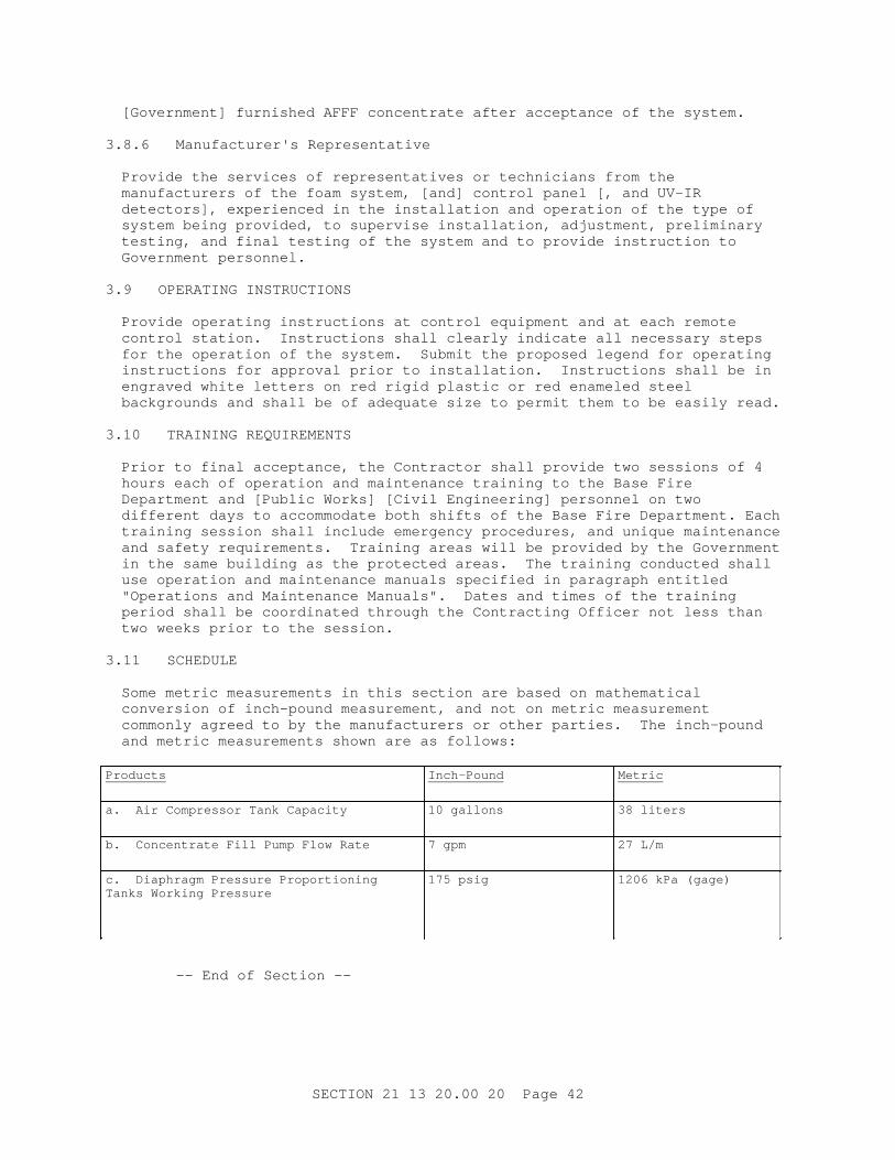
[ Gover nment ] f ur ni shed AFFF concent r at e af t er accept ance of t he syst em.
3. 8. 6 Manuf act ur er ' s Repr esent at i ve
Pr ovi de t he ser v i ces of r epr esent at i ves or t echni c i ans f r om t he manuf act ur er s of t he f oam syst em, [ and] cont r ol panel [ , and UV- I R det ect or s] , exper i enced i n t he i nst al l at i on and oper at i on of t he t ype of syst em bei ng pr ovi ded, t o super vi se i nst al l at i on, adj ust ment , pr el i mi nar y t est i ng, and f i nal t est i ng of t he syst em and t o pr ovi de i nst r uct i on t o Gover nment per sonnel .
3. 9 OPERATI NG I NSTRUCTI ONS
Pr ovi de oper at i ng i nst r uct i ons at cont r ol equi pment and at each r emot e cont r ol st at i on. I nst r uct i ons shal l c l ear l y i ndi cat e al l necessar y st eps f or t he oper at i on of t he syst em. Submi t t he pr oposed l egend f or oper at i ng i nst r uct i ons f or appr oval pr i or t o i nst al l at i on. I nst r uct i ons shal l be i n engr aved whi t e l et t er s on r ed r i gi d pl ast i c or r ed enamel ed st eel backgr ounds and shal l be of adequat e s i ze t o per mi t t hem t o be easi l y r ead.
3. 10 TRAI NI NG REQUI REMENTS
Pr i or t o f i nal accept ance, t he Cont r act or shal l pr ovi de t wo sessi ons of 4 hour s each of oper at i on and mai nt enance t r ai ni ng t o t he Base Fi r e Depar t ment and [ Publ i c Wor ks] [ Ci v i l Engi neer i ng] per sonnel on t wo di f f er ent days t o accommodat e bot h shi f t s of t he Base Fi r e Depar t ment . Each t r ai ni ng sessi on shal l i ncl ude emer gency pr ocedur es, and uni que mai nt enance and saf et y r equi r ement s. Tr ai ni ng ar eas wi l l be pr ovi ded by t he Gover nment i n t he same bui l di ng as t he pr ot ect ed ar eas. The t r ai ni ng conduct ed shal l use oper at i on and mai nt enance manual s speci f i ed i n par agr aph ent i t l ed " Oper at i ons and Mai nt enance Manual s" . Dat es and t i mes of t he t r ai ni ng per i od shal l be coor di nat ed t hr ough t he Cont r act i ng Of f i cer not l ess t han t wo weeks pr i or t o t he sessi on.
3. 11 SCHEDULE
Some met r i c measur ement s i n t hi s sect i on ar e based on mat hemat i cal conver si on of i nch- pound measur ement , and not on met r i c measur ement commonl y agr eed t o by t he manuf act ur er s or ot her par t i es. The i nch- pound and met r i c measur ement s shown ar e as f ol l ows:
Products Inch-Pound Metric
a. Ai r Compr essor Tank Capaci t y 10 gal l ons 38 l i t er s
b. Concent r at e Fi l l Pump Fl ow Rat e 7 gpm 27 L/ m
c. Di aphr agm Pr essur e Pr opor t i oni ng Tanks Wor ki ng Pr essur e
175 psi g 1206 kPa ( gage)
- - End of Sect i on - -
SECTI ON 21 13 20. 00 20 Page 42