Embed Size (px)
Citation preview
**************************************************************************USACE / NAVFAC / AFCEC / NASA UFGS- 23 51 43. 02 20 ( Apr i l 2006) - - - - - - - - - - - - - - - - - - - - - - - - - - - - - - - -Pr epar i ng Act i v i t y: NAVFAC Repl aci ng wi t hout change UFGS- 15862N ( Sept ember 1999)
UNI FI ED FACI LI TI ES GUI DE SPECI FI CATI ONS
Ref er ences ar e i n agr eement wi t h UMRL dat ed Januar y 2020**************************************************************************
SECTION TABLE OF CONTENTS
DIVISION 23 - HEATING, VENTILATING, AND AIR CONDITIONING (HVAC)
SECTION 23 51 43.02 20
ELECTROSTATIC DUST COLLECTOR OF FLUE GAS PARTICULATES
04/06
PART 1 GENERAL
1.1 REFERENCES 1.2 DEFINITIONS 1.3 DESCRIPTION 1.3.1 Electrostatic Dust Collector Layout and Component Drawings 1.3.2 Hopper Heater Drawings 1.3.3 Dust Collection System 1.4 PERFORMANCE 1.5 OPERATING EXPERIENCE REQUIREMENTS 1.5.1 Equipment 1.5.2 Experience Required 1.5.3 List of Prior Installations Contents 1.6 MODEL TEST 1.6.1 Precipitator Model Tests Reports 1.6.2 Reports 1.7 SUBMITTALS 1.8 DELIVERY AND STORAGE 1.9 DESIGN CRITERIA 1.9.1 Boiler Data 1.9.2 Mechanical Collector Data 1.9.3 Inlet Gas Conditions 1.9.4 Precipitator Data 1.9.5 Breeching 1.9.6 Coordination 1.9.7 Electrostatic Dust Collector System 1.10 AMBIENT ENVIRONMENT IN VICINITY OF ELECTRICAL EQUIPMENT 1.11 MISCELLANEOUS 1.12 DELIVERY OF MODEL
PART 2 PRODUCTS
2.1 MATERIALS 2.2 STRUCTURAL SUPPORTS 2.3 ELECTRICAL REQUIREMENTS 2.3.1 Electrical Scope of Work
SECTION 23 51 43.02 20 Page 1

2.3.1.1 Material and Workmanship 2.3.1.2 Electrical Supply Voltage 2.3.1.3 Transformers 2.3.2 Equipment Enclosure Heaters 2.3.2.1 Equipment Enclosure Nameplates 2.3.2.2 Equipment Enclosure Grounding 2.3.2.3 Insulation and Weatherproofing 2.3.2.4 Wiring 2.3.3 Transformer-Rectifier (T-R) Set 2.3.3.1 Rectifier 2.3.3.2 Grounding Switches 2.3.3.3 Transformer Oil 2.3.4 Control Cabinet 2.3.4.1 Arc Suppression Within the Precipitator 2.3.4.2 Auxiliary Alarm 2.3.4.3 Pushbutton Stations 2.3.4.4 Redundant Protective Devices 2.3.5 High Voltage System Wiring and Support Insulators 2.3.6 High-Voltage Leads 2.3.7 High Voltage Insulators 2.3.8 High Voltage Insulator and Pressurizing System Heaters 2.3.9 Discharge Electrodes and Collecting Surfaces 2.3.10 Rappers 2.3.10.1 Rapper Controls 2.3.10.2 Rapper Control System 2.3.10.3 Rapper Disconnects 2.3.10.4 Rapper High Voltage Spikes 2.3.10.5 Rapper Annunciation 2.3.11 Annunciation and Indication 2.3.11.1 Off-Limit Conditions 2.3.11.2 Annunciator 2.3.12 Electrical Service Outlets 2.4 HOUSING 2.4.1 Penthouse 2.4.2 Insulation Materials 2.4.3 Casing Materials 2.5 HOPPERS 2.5.1 Hopper Accessories 2.5.2 Hopper Vibrators 2.5.3 Hopper Heater System 2.5.3.1 Hopper Heater System Design 2.5.3.2 Hopper Heater Controls 2.5.4 Fly Ash Level Alarms 2.5.4.1 Temperature Range Requirement 2.5.4.2 Cesium Source Safety Systems 2.5.4.3 Hopper Level Indicator 2.5.4.4 Alarm System 2.6 ACCESS 2.6.1 Walkways 2.6.2 Doors 2.6.3 Platforms, Walkways, and Ladders 2.6.4 Maintenance 2.6.5 Hot Dip Galvanizing 2.6.6 Gas Distribution Devices 2.6.7 Interlocks 2.7 FABRICATION 2.8 PAINTING
PART 3 EXECUTION
SECTION 23 51 43.02 20 Page 2

3.1 FACTORY INSPECTION 3.2 INSTALLATION 3.3 MANUFACTURER'S FIELD REPRESENTATIVE 3.4 FIELD TESTS AND INSPECTIONS 3.4.1 Delivery Inspection 3.4.2 Post Installation Inspection 3.4.3 Performance Tests 3.5 IDENTIFICATION 3.6 INSULATION INSTALLATION 3.6.1 General Insulation Requirements 3.6.2 Block and Mineral Fiberboard Insulation Installation 3.6.3 Mineral Fiber Blanket Insulation Installation 3.6.4 Housing Hot Roof 3.7 PROTECTION FROM INSULATION MATERIALS 3.8 CASING INSTALLATION 3.8.1 Structural Steel Grid System 3.8.2 Access Openings 3.8.3 Weatherproofing 3.8.4 Convection Stops 3.8.5 Casing Attachment 3.9 HEATER INSTALLATION 3.10 WIRE NUMBERS 3.11 GALVANIC CORROSION PREVENTION 3.12 PAINTING 3.13 SCHEDULE
-- End of Section Table of Contents --
SECTION 23 51 43.02 20 Page 3

**************************************************************************USACE / NAVFAC / AFCEC / NASA UFGS- 23 51 43. 02 20 ( Apr i l 2006) - - - - - - - - - - - - - - - - - - - - - - - - - - - - - - - -Pr epar i ng Act i v i t y: NAVFAC Repl aci ng wi t hout change UFGS- 15862N ( Sept ember 1999)
UNI FI ED FACI LI TI ES GUI DE SPECI FI CATI ONS
Ref er ences ar e i n agr eement wi t h UMRL dat ed Januar y 2020**************************************************************************
SECTION 23 51 43.02 20
ELECTROSTATIC DUST COLLECTOR OF FLUE GAS PARTICULATES04/06
**************************************************************************NOTE: Thi s gui de speci f i cat i on cover s t he r equi r ement s f or f ur ni shi ng, i nst al l i ng, adj ust i ng, and t est i ng of el ect r ost at i c pr eci pi t at or ( s) .
Adher e t o UFC 1-300-02 Uni f i ed Faci l i t i es Gui de Speci f i cat i ons ( UFGS) For mat St andar d when edi t i ng t hi s gui de speci f i cat i on or pr epar i ng new pr oj ect speci f i cat i on sect i ons. Edi t t hi s gui de speci f i cat i on f or pr oj ect speci f i c r equi r ement s by addi ng, del et i ng, or r evi s i ng t ext . For br acket ed i t ems, choose appl i cabl e i t em( s) or i nser t appr opr i at e i nf or mat i on.
Remove i nf or mat i on and r equi r ement s not r equi r ed i n r espect i ve pr oj ect , whet her or not br acket s ar e present.
Comment s, suggest i ons and r ecommended changes f or t hi s gui de speci f i cat i on ar e wel come and shoul d be submi t t ed as a Criteria Change Request (CCR) .
**************************************************************************
**************************************************************************NOTE: The pr eci pi t at or ( s) i s i nt ended t o be used f or f l ue gas par t i cul at e r emoval and col l ect i on associ at ed wi t h coal - f i r ed boi l er s and r ef use- f i r ed wast e di sposal i nci ner at or s. Coal - f i r ed boi l er s appl i cabl e t o t hi s speci f i cat i on ar e t hose desi gned wi t h capaci t i es r angi ng bet ween 3. 78 and 31. 5 k i l ogr am of st eam per second 30, 000 and 250, 000 pounds of st eam per hour . The i nci ner at or s appl i cabl e t o t hi s speci f i cat i on ar e t hose desi gned f or bur ni ng muni ci pal - t ype wast e havi ng f i r i ng capaci t i es bet ween 454 ki l ogr am per hour 1, 000 pounds per hour and 182 Mg 200 t ons per day. For engi neer i ng and desi gn assi st ance on pr eci pi t at or s appl i ed c l ose t o or out si de t hese capaci t i es, contact:
Commandi ng Of f i cer ( ESC Code 433)NAVFAC Engi neer i ng Ser vi ce Cent er
SECTION 23 51 43.02 20 Page 4
560 Cent er Dr i vePor t Hueneme, CA 93043- 4340Tel ephone: ( 805) 982- 4984
Ther e ar e pr obabl y no pr eci pi t at or manuf act ur er s t hat can meet al l t he speci f i cat i ons. Di scr et i on must be exer ci sed t o det er mi ne whi ch devi at i ons ar e acceptable.
**************************************************************************
PART 1 GENERAL
1.1 REFERENCES
**************************************************************************NOTE: Thi s par agr aph i s used t o l i s t t he publ i cat i ons c i t ed i n t he t ext of t he gui de speci f i cat i on. The publ i cat i ons ar e r ef er r ed t o i n t he t ext by basi c desi gnat i on onl y and l i s t ed i n t hi s par agr aph by or gani zat i on, desi gnat i on, dat e, and t i t l e. Use t he Ref er ence Wi zar d' s Check Ref er ence f eat ur e when you add a Ref er ence I dent i f i er ( RI D) out si de of t he Sect i on' s Ref er ence Ar t i c l e t o aut omat i cal l y pl ace t he r ef er ence i n t he Ref er ence Ar t i c l e. Al so use t he Ref er ence Wi zar d' s Check Ref er ence f eat ur e t o updat e t he i ssue dat es. Ref er ences not used i n t he t ext wi l l aut omat i cal l y be del et ed f r om t hi s sect i on of t he pr oj ect speci f i cat i on when you choose t o r econci l e r ef er ences i n t he publ i sh pr i nt pr ocess.
**************************************************************************
The publications listed below form a part of this specification to the extent referenced. The publications are referred to within the text by the basic designation only.
AMERICAN INSTITUTE OF STEEL CONSTRUCTION (AISC)
AISC 360 (2016) Specification for Structural Steel Buildings
AMERICAN WELDING SOCIETY (AWS)
AWS D1.1/D1.1M (2015; Errata 1 2015; Errata 2 2016) Structural Welding Code - Steel
ASTM INTERNATIONAL (ASTM)
ASTM A36/A36M (2014) Standard Specification for Carbon Structural Steel
ASTM A123/A123M (2017) Standard Specification for Zinc (Hot-Dip Galvanized) Coatings on Iron and Steel Products
ASTM A242/A242M (2013; R 2018) Standard Specification for
SECTION 23 51 43.02 20 Page 5

High-Strength Low-Alloy Structural Steel
ASTM A276/A276M (2017) Standard Specification for Stainless Steel Bars and Shapes
ASTM A325 (2014) Standard Specification for Structural Bolts, Steel, Heat Treated, 120/105 ksi Minimum Tensile Strength
ASTM A325M (2014) Standard Specification for Structural Bolts, Steel, Heat Treated, 830 MPa Minimum Tensile Strength (Metric)
ASTM A490 (2014a) Standard Specification for Structural Bolts, Alloy Steel, Heat Treated, 150 ksi Minimum Tensile Strength
ASTM A490M (2014a) Standard Specification for High-Strength Steel Bolts, Classes 10.9 and 10.9.3, for Structural Steel Joints (Metric)
ASTM A580/A580M (2018) Standard Specification for Stainless Steel Wire
ASTM B209 (2014) Standard Specification for Aluminum and Aluminum-Alloy Sheet and Plate
ASTM B209M (2014) Standard Specification for Aluminum and Aluminum-Alloy Sheet and Plate (Metric)
ASTM C533 (2017) Standard Specification for Calcium Silicate Block and Pipe Thermal Insulation
ASTM C592 (2016) Standard Specification for Mineral Fiber Blanket Insulation and Blanket-Type Pipe Insulation (Metal-Mesh Covered) (Industrial Type)
ASTM C612 (2014; R 2019) Mineral Fiber Block and Board Thermal Insulation
ASTM D877/D877M (2013) Standard Test Method for Dielectric Breakdown Voltage of Insulating Liquids Using Disk Electrodes
ASTM D923 (2007) Standard Practice for Sampling Electrical Insulating Liquids
INSTITUTE OF CLEAN AIR COMPANIES (ICAC)
ICAC EP-1 (2000) Terminology for Electrostatic Precipitators
ICAC EP-6 (1968) Pilot Electrostatic Precipitators
ICAC EP-7 (2004) Electrostatic Precipitator Gas Flow Model Studies
SECTION 23 51 43.02 20 Page 6
ICAC EP-8 (1993) Structural Design Criteria for Electrostatic Precipitator Casings
ICAC EP-10W (2008) Bid Specification Information Requirements and Bid Evaluation Form for Electrostatic Precipitators
INTERNATIONAL ELECTROTECHNICAL COMMISSION (IEC)
IEC 60309-3 Pin and Sleeve Devices
NATIONAL ELECTRICAL MANUFACTURERS ASSOCIATION (NEMA)
NEMA ICS 1 (2000; R 2015) Standard for Industrial Control and Systems: General Requirements
NEMA ICS 2 (2000; R 2005; Errata 2008) Industrial Control and Systems Controllers, Contactors, and Overload Relays Rated 600 V
NEMA ICS 6 (1993; R 2016) Industrial Control and Systems: Enclosures
NATIONAL FIRE PROTECTION ASSOCIATION (NFPA)
NFPA 70 (2017; ERTA 1-2 2017; TIA 17-1; TIA 17-2; TIA 17-3; TIA 17-4; TIA 17-5; TIA 17-6; TIA 17-7; TIA 17-8; TIA 17-9; TIA 17-10; TIA 17-11; TIA 17-12; TIA 17-13; TIA 17-14; TIA 17-15; TIA 17-16; TIA 17-17 ) National Electrical Code
SHEET METAL AND AIR CONDITIONING CONTRACTORS' NATIONAL ASSOCIATION (SMACNA)
SMACNA 1793 (2012) Architectural Sheet Metal Manual, 7th Edition
SOCIETY FOR PROTECTIVE COATINGS (SSPC)
SSPC PS 12.01 (2002; E 2004) One Coat Zinc-Rich Painting System
SSPC SP 1 (2015) Solvent Cleaning
SSPC SP 6/NACE No.3 (2007) Commercial Blast Cleaning
U.S. NATIONAL ARCHIVES AND RECORDS ADMINISTRATION (NARA)
40 CFR 60 Standards of Performance for New Stationary Sources
1.2 DEFINITIONS
Electrostatic precipitator terminology shall be in accordance with ICAC EP-1 except for the following:
a. Aspect Ratio: Effective treatment length divided by effective collection plate height.
SECTION 23 51 43.02 20 Page 7
b. Collection Surface Area: Area of vertical grounded plates parallel to the gas flow. The area of components in walkways, hoppers, discharge electrical surfaces, inlet plenums, and outlet plenums shall be excluded. Exclude area of plates above or below the uniform gas flow.
c. Effective Collection Plate Height: Vertical height of the grounded collection plate in contact with the flue gas.
d. Effective Treatment Length: Horizontal length of the grounded collection plates parallel to the gas flow in a single passage in the direction of gas flow. Exclude walkways, inlet plenums, and outlet plenums.
e. Specific Collection Area: Total grounded collection surface area, in square meter feet , divided by maximum gas flow rate.
f. Rigid Frame Type: Typical design in which the discharge electrodes are fastened in a support frame of welded horizontal and vertical masts suspended from four support insulators.
g. Hot Roof: Top section of the precipitator casing between the penthouse and the gas stream.
h. Penthouse Roof: The walking surface on top of the penthouse; that is, the raised pattern plate that covers the top of the penthouse casing insulation.
i. Plate Spacing: Center to center spacing of the grounded collecting electrode surfaces.
1.3 DESCRIPTION
**************************************************************************NOTE:
1. I f f l y ash condi t i oni ng or r emoval pr i or t o t he pr eci pi t at or i s i ncl uded i n t he desi gn, t he syst em shoul d be descr i bed.
2. I f i t i s ant i c i pat ed t hat t he ef f i c i ency of t he pr eci pi t at or wi l l be i ncr eased by t he addi t i on of f i el d( s) i n t he f ut ur e, t hi s shoul d be descr i bed.
3. I f i t i s desi r ed t hat t he i nl et and out l et br eechi ng be f ur ni shed and/ or desi gned by t he col l ect or manuf act ur er , i t shoul d be descr i bed.
4. Speci f y t he ESP l ocat i on and br eechi ng t i e points.
**************************************************************************
Provide electrostatic precipitator(s) of the rigid frame type designed in accordance with ICAC EP-1 , ICAC EP-10W , ICAC EP-6 , ICAC EP-7 , and ICAC EP-8 to remove fly ash from flue gas produced by a [pulverized coal-fired boiler] [spreader stoker-fired boiler] [underfeed stoker-fired boiler] [refuse-fired waste disposal incinerator]. Provide precipitator(s) suitable for [indoor] [outdoor] installation. Locate the precipitator(s) in the flue gas system between the [_____] and the [_____].
SECTION 23 51 43.02 20 Page 8
1.3.1 Electrostatic Dust Collector Layout and Component Drawings
Drawings shall indicate the kind, size, arrangement, weight of each component, and breakdown for shipment; the external connections, location of local controls, remote control panels, anchorages, and supports required; the dimensions needed for installation and correlation with other materials and equipment; seismic structural calculations; and foundation and loading information. Supply drawings for each component showing design and assembly. Provide schematics of all electrical and pneumatic circuits used. Submission shall include, but shall not be limited to the following details:
a. Transformer-rectifier equipment.
b. High voltage switches and disconnects.
c. High voltage fuses and circuit breakers.
d. Control systems.
e. Ground lugs.
f. Protection against electrolysis.
g. Graphic display panel indicating power components.
h. Lubrication locations.
i. Electrodes and collecting surfaces.
j. Platforms, walkways, stairways, and ladders which will be required for operation, inspection, testing, and maintenance, and furnished with the precipitator.
k. Location of field welds, in conformance to AWS D1.1/D1.1M .
1.3.2 Hopper Heater Drawings
Provide layout drawings, wiring diagrams, and control schematics diagrams. Layout drawings shall show each hopper face including control zones.
1.3.3 Dust Collection System
Submit a full description of the system proposed, including arrangement, operation, and maintenance of the discharge electrodes and collecting surfaces. Indicate planned rapping cycle and performance test details and sampling location. Describe electrodes and collecting surfaces.
1.4 PERFORMANCE
**************************************************************************NOTE:
1. Sel ect ei t her a col l ect i on ef f i c i ency or out l et dust l oadi ng condi t i on, whi chever i s mor e st r i ngent .
2. The st ack emi ssi on or ef f i c i ency r equi r ement s must compl y wi t h ( a) wei ght emi ssi on st andar ds; ( b)
SECTION 23 51 43.02 20 Page 9
opaci t y r egul at i ons; and ( c) communi t y st andar ds f or v i s i bl e emi ssi ons. Compl i ance wi t h exi st i ng emi ssi on codes may not sat i sf y t he opaci t y r egul at i on. Si mi l ar l y, opaci t y r egul at i ons may not be as demandi ng as communi t y st andar ds. A speci f i c quant i t at i ve emi ssi on r at e must be sel ect ed on t he basi s of t he goal s est abl i shed.
3. St ack opaci t y i s i nf l uenced by par t i c l e s i ze makeup. For exampl e, wi t h pul ver i zed coal - f i r ed boi l er s, about 45 per cent of t he ash par t i c l es ar e bel ow 10 mi cr ons i n s i ze; f or a cycl one- f i r ed boi l er , about 70 per cent ar e bel ow 10 mi cr ons; f or a st oker - f i r ed boi l er , about 25 per cent ar e bel ow 10 mi cr ons. A v i sual l y accept abl e st ack f or t hese t hr ee opt i ons mi ght r equi r e r esi dual s of 0. 046 g/ m3 0. 02 gr per acf , 0. 023 g/ m3 0. 01 gr per acf , and 0. 092 g/ m3 0. 04 gr per acf , r espect i vel y.
4. I f i t i s det er mi ned t hat a spar e or addi t i onal pr eci pi t at or sect i on i s desi r abl e t o i ncr ease r el i abi l i t y , t he speci f i cat i on shoul d be modi f i ed so t hat t he per f or mance can be met wi t h any one sect i on out of ser vi ce.
**************************************************************************
The precipitator shall operate at a [dust collection efficiency of not less than [_____] percent] [dust loading at the precipitator outlet of not more than [_____] grams per liter grains per standard cubic foot ], as measured using EPA method 5, when operating continuously at the maximum continuous rating of flue gas flow conditions and dust loading specified in paragraph entitled "Inlet Gas Conditions." The collection efficiency shall not be limited because of variations in dust resistivity levels. Flue gas conditioning by injection of sulfur-trioxide, ammonia, or other substance shall not be an acceptable method of achieving performance.
1.5 OPERATING EXPERIENCE REQUIREMENTS
1.5.1 Equipment
Provide dust collectors which meets all of the operating experience requirements listed below.
1.5.2 Experience Required
**************************************************************************NOTE: Al l ow onl y oper at i ng exper i ence t r eat i ng f l ue gas f r om t he equi pment speci f i ed i n par agr aph ent i t l ed " Desi gn Cr i t er i a" and of t he appr oxi mat e L/ s acf m, t emper at ur e and i nl et gr ai n l oadi ng as t hat speci f i ed i n par agr aph ent i t l ed " I nl et Gas Conditions."
**************************************************************************
The manufacturer has constructed not less than three electrostatic precipitators each at a separate facility, treating flue gas from [a refuse-fired waste disposal incinerator] [a coal-fired boiler] with [automatic] [manual] combustion control. Each precipitator shall have performed satisfactorily, normal maintenance or downtime of the associated
SECTION 23 51 43.02 20 Page 10
[boiler] [incinerator] [dust collector] included, for a period of not less than 2 years treating at least [_____] L/s acfm of inlet gas at a temperature of at least [_____] degrees C F , with inlet dust loading of at least [_____] grams per liter grains per acf and outlet dust loading of at most [_____] grams per liter grains per acf .
1.5.3 List of Prior Installations Contents
Submit a certificate from the manufacturer containing the information outlined below within 30 days after award and prior to commencement of installation. Information to be contained in the certificate shall include:
a. A list of at least three installations at separate facilities meeting the requirements set forth above.
b. Owner, location, point of contact, and phone number of each such installation.
c. Date of owner acceptance of each such installation.
d. Design inlet gas volume, L/s acfm ; inlet gas temperature, degrees C F ; inlet dust loading, grams per liters grains per acf ; and outlet dust loading, grams per liter grains per acf .
e. Type of [coal-fired boiler] [refuse-fired waste disposal incinerator].
1.6 MODEL TEST
**************************************************************************NOTE: Gener al l y, t he compl et e gas syst em i s i ncl uded i n t he model t est .
**************************************************************************
The precipitator manufacturer or a Contracting Officer approved independent modeling and testing lab shall perform a three dimensional model test of not less than 1:100 1/8 scale. Hold all model dimensions to within plus or minus 1.50 mm 1/16 inch . The precipitator manufacturer or testing lab shall have at least five years experience in conducting electrostatic precipitator model tests. (The five years of experience is required prior to proposal submittal.) The test shall determine the gas flow patterns in accordance with ICAC EP-7 procedures, the potential areas of dust accumulation using sifted bleached wheat flour and neutral buoyancy bubbles, velocity distribution, and potential pressure drop reductions through the precipitator, nozzles, and breeching. Model breeching and particulate control equipment from [_____] to [_____]. Include precipitator hoppers, collection plates, distribution devices, turning vanes, anti-sneak baffles and internal bracing and supports. Simulate the cyclones to represent the adversely affected gas flow distribution from the cyclones. Perform flow and dust distribution tests at 30, 50, 75, 100, and 125 percent of maximum continuous flow rating. Notify the Contracting Officer of test dates in writing not less than 14 calendar days before tests are to begin.
1.6.1 Precipitator Model Tests Reports
**************************************************************************NOTE: I ncl ude ot her t est l ocat i ons of concer n based on t he pr el i mi nar y br eechi ng desi gn. These may
SECTION 23 51 43.02 20 Page 11

i ncl ude i nl et s t o i nduced dr af t f ans and st acks as wel l as bypass br eechi ng.
**************************************************************************
Complete model testing and have approved by the Contracting Officer prior to submittal of drawings. Provide reports within 30 days of test completion. Include a scale drawing of the model showing actual dimensions and a scale drawing of the full-size installation showing modifications made and devices added to the breeching and transitions as a result of the model study. Include uniform gas velocity diagrams and histograms, indicating the root mean square velocity deviation, standard deviation, and mean velocity, at strategic locations which shall include, but not be limited to, the following:
a. Inlet to electrostatic precipitator.
b. Outlet of electrostatic precipitator.
Provide a complete explanation of the test procedures including flow rates, pressures, sample calculations and assumptions prior to testing. List and justify deviations in dynamic or geometric similitude by the model from the full-size installation. The test report shall recommend breeching configuration changes, gas flow vaning, straightening or other gas distribution devices in the system required to meet ICAC EP-7 requirements and gas distribution specified in paragraph entitled "Gas Distribution Devices." Incorporate devices required for specified gas distribution and modifications necessary to the proposed breeching, that result from model testing, into the final breeching design. Recommend the location of test ports, the location and type of flow distribution devices in stack, and the location of gas flow instrumentation points and monitors. Provide a complete listing of pressure drop data taken at each pressure tap during each test run and also include data from runs before and after the addition of supplemental flow distribution devices that correct distribution problems identified by initial runs. Locate pressure tap as required to accurately determine the pressure drop across critical breeching components and the effect of the additional distribution devices on the pressure drop. Submit with the report a complete set of photographs and videotape recordings of model during air flow test.
1.6.2 Reports
For precipitator inspection , submit report of the factory service engineer's inspection within 15 calendar days after the inspection stating his findings including the acceptability of the precipitator for field performance tests. Submit air load test report with the precipitator inspection report. With performance test reports, certify that instruments were calibrated and readings indicated are true. Include certification that computations required for testing are accurate, that acceptable methods were used, and that the equipment performed in accordance with the requirements. For precipitator calibration , include certification that computations required for testing are accurate, and that acceptable methods were used.
1.7 SUBMITTALS
**************************************************************************NOTE: Revi ew Submi t t al Descr i pt i on ( SD) def i ni t i ons i n Sect i on 01 33 00 SUBMI TTAL PROCEDURES and edi t t he f ol l owi ng l i s t t o r ef l ect onl y t he submi t t al s
SECTION 23 51 43.02 20 Page 12

r equi r ed f or t he pr oj ect .
The Gui de Speci f i cat i on t echni cal edi t or s have desi gnat ed t hose i t ems t hat r equi r e Gover nment appr oval , due t o t hei r compl exi t y or cr i t i cal i t y, wi t h a " G" . Gener al l y, ot her submi t t al i t ems can be r evi ewed by t he Cont r act or ' s Qual i t y Cont r ol Syst em. Onl y add a “ G” t o an i t em, i f t he submi t t al i s suf f i c i ent l y i mpor t ant or compl ex i n cont ext of t he pr oj ect .
For submi t t al s r equi r i ng Gover nment appr oval on Ar my pr oj ect s, a code of up t o t hr ee char act er s wi t hi n t he submi t t al t ags may be used f ol l owi ng t he " G" desi gnat i on t o i ndi cat e t he appr ovi ng aut hor i t y. Codes f or Ar my pr oj ect s usi ng t he Resi dent Management Syst em ( RMS) ar e: " AE" f or Ar chi t ect - Engi neer ; " DO" f or Di st r i ct Of f i ce ( Engi neer i ng Di v i s i on or ot her or gani zat i on i n t he Di st r i ct Of f i ce) ; " AO" f or Ar ea Of f i ce; " RO" f or Resi dent Of f i ce; and " PO" f or Pr oj ect Of f i ce. Codes f ol l owi ng t he " G" t ypi cal l y ar e not used f or Navy, Ai r For ce, and NASA pr oj ect s.
The " S" f ol l owi ng a submi t t al i t em i ndi cat es t hat t he submi t t al i s r equi r ed f or t he Sust ai nabi l i t y eNot ebook t o f ul f i l l f eder al l y mandat ed sust ai nabl e r equi r ement s i n accor dance wi t h Sect i on 01 33 29 SUSTAI NABI LI TY REPORTI NG. Locat e t he " S" submi t t al under t he SD number t hat best descr i bes t he submi t t al i t em.
Choose t he f i r st br acket ed i t em f or Navy, Ai r For ce and NASA pr oj ect s, or choose t he second br acket ed i t em f or Ar my pr oj ect s.
**************************************************************************
Government approval is required for submittals with a "G" designation; submittals not having a "G" designation are [for Contractor Quality Control approval.][for information only. When used, a designation following the "G" designation identifies the office that will review the submittal for the Government.] Submittals with an "S" are for inclusion in the Sustainability eNotebook, in conformance to Section 01 33 29 SUSTAINABILITY REPORTING. Submit the following in accordance with Section 01 33 00 SUBMITTAL PROCEDURES:
SD-02 Shop Drawings
Electrostatic dust collector
Hopper heater
SD-03 Product Data
Warning signs
SD-05 Design Data
Dust collection system
SECTION 23 51 43.02 20 Page 13

SD-06 Test Reports
Precipitator model tests
Hopper heater module voltage tests
Precipitator inspection
Air load test
Performance tests
Precipitator calibration
SD-07 Certificates
List of prior installations
SD-10 Operation and Maintenance Data
Electrostatic dust collector system , Data Package 3
Submit in accordance with Section 01 78 23 OPERATION AND MAINTENANCE DATA.
1.8 DELIVERY AND STORAGE
Ship equipment completely factory assembled, except when the physical size, arrangement, or configuration of the equipment, or shipping limitations, makes the shipment of completely assembled equipment impracticable, in which case assemble the equipment and ship as stated in the Contractor's proposal. Provide storage and protection of delivered equipment in accordance with manufacturer's recommendations.
1.9 DESIGN CRITERIA
1.9.1 [ Boiler Data
**************************************************************************NOTE: Sel ect t he appl i cabl e par agr aph( s) f r om t he following:
**************************************************************************
**************************************************************************NOTE: I ncl ude ash anal ysi s i f avai l abl e. Speci f y r ange of pr oper t i es f or coal .
**************************************************************************
**************************************************************************NOTE: I nser t appr opr i at e Sect i on number and t i t l e i n t he bl anks bel ow usi ng f or mat per UFC 1- 300- 02.
**************************************************************************
Provide electrostatic precipitator(s) for operation with [the boiler(s) specified in [_____]] [boiler(s) manufactured by [_____], Type [_____], Model No. [_____]]. The boiler is a [new] [existing] [pulverized coal-fired] [spreader stoker-fired] [underfeed stoker-fired] boiler rated [_____] kilogram per second pounds per hour of steam at [_____] kPa psi ,
SECTION 23 51 43.02 20 Page 14
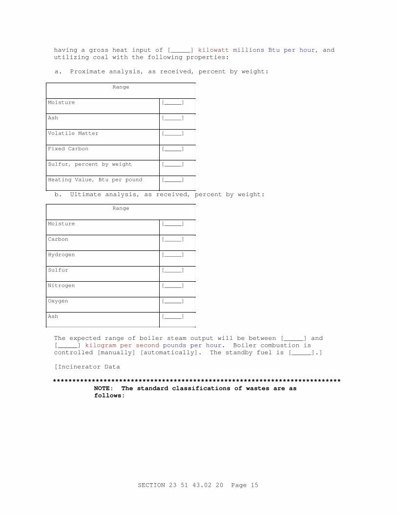
having a gross heat input of [_____] kilowatt millions Btu per hour , and utilizing coal with the following properties:
a. Proximate analysis, as received, percent by weight:
Range
Moisture [_____]
Ash [_____]
Volatile Matter [_____]
Fixed Carbon [_____]
Sulfur, percent by weight [_____]
Heating Value, Btu per pound [_____]
b. Ultimate analysis, as received, percent by weight:
Range
Moisture [_____]
Carbon [_____]
Hydrogen [_____]
Sulfur [_____]
Nitrogen [_____]
Oxygen [_____]
Ash [_____]
The expected range of boiler steam output will be between [_____] and [_____] kilogram per second pounds per hour . Boiler combustion is controlled [manually] [automatically]. The standby fuel is [_____].]
[Incinerator Data
**************************************************************************NOTE: The st andar d c l assi f i cat i ons of wast es ar e as follows:
SECTION 23 51 43.02 20 Page 15
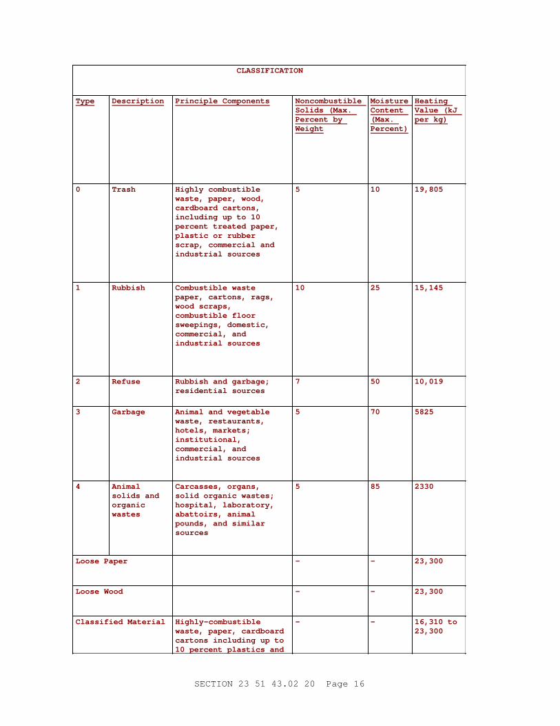
CLASSIFICATION
Type Description Pr i nci pl e Component s Noncombustible Sol i ds ( Max. Per cent by Weight
Moisture Content (Max. Percent)
Heating Val ue ( kJ per kg)
0 Trash Hi ghl y combust i bl e wast e, paper , wood, car dboar d car t ons, i ncl udi ng up t o 10 per cent t r eat ed paper , pl ast i c or r ubber scr ap, commer ci al and i ndust r i al sour ces
5 10 19,805
1 Rubbish Combust i bl e wast e paper , car t ons, r ags, wood scr aps, combust i bl e f l oor sweepi ngs, domest i c, commer ci al , and i ndust r i al sour ces
10 25 15,145
2 Refuse Rubbi sh and gar bage; r esi dent i al sour ces
7 50 10,019
3 Garbage Ani mal and veget abl e wast e, r est aur ant s, hot el s, mar ket s; institutional, commer ci al , and i ndust r i al sour ces
5 70 5825
4 Animal sol i ds and organic wastes
Car casses, or gans, sol i d or gani c wast es; hospi t al , l abor at or y, abat t oi r s, ani mal pounds, and si mi l ar sources
5 85 2330
Loose Paper - - 23,300
Loose Wood - - 23,300
Cl assi f i ed Mat er i al Highly-combustible wast e, paper , car dboar d car t ons i ncl udi ng up t o 10 per cent pl ast i cs and
- - 16, 310 t o 23,300
SECTION 23 51 43.02 20 Page 16
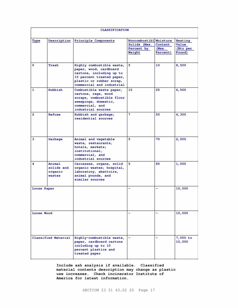
CLASSIFICATION
Type Description Pr i nci pl e Component s Noncombustible Sol i ds ( Max. Per cent by Weight
Moisture Content (Max. Percent)
Heating Value ( Bt u per Pound)
0 Trash Hi ghl y combust i bl e wast e, paper , wood, car dboar d car t ons, i ncl udi ng up t o 10 per cent t r eat ed paper , pl ast i c or r ubber scr ap, commer ci al and i ndust r i al sources
5 10 8,500
1 Rubbish Combust i bl e wast e paper , car t ons, r ags, wood scr aps, combust i bl e f l oor sweepi ngs, domest i c, commer ci al , and i ndust r i al sour ces
10 25 6,500
2 Refuse Rubbi sh and gar bage; r esi dent i al sour ces
7 50 4,300
3 Garbage Ani mal and veget abl e wast e, r est aur ant s, hot el s, mar ket s; institutional, commer ci al , and i ndust r i al sour ces
5 70 2,500
4 Animal sol i ds and organic wastes
Car casses, or gans, sol i d or gani c wast es; hospi t al , l abor at or y, abat t oi r s, ani mal pounds, and si mi l ar sour ces
5 85 1,000
Loose Paper - - 10,000
Loose Wood - - 10,000
Cl assi f i ed Mat er i al Hi ghl y- combust i bl e wast e, paper , car dboar d car t ons i ncl udi ng up t o 10 per cent pl ast i cs and t r eat ed paper
- - 7, 000 t o 10,000
I ncl ude ash anal ysi s i f avai l abl e. Cl assi f i ed mat er i al cont ent s descr i pt i on may change as pl ast i c use i ncr eases. Check i nci ner at or I nst i t ut e of Amer i ca f or l at est i nf or mat i on.
SECTION 23 51 43.02 20 Page 17
**************************************************************************
**************************************************************************NOTE: I nser t appr opr i at e Sect i on number and t i t l e i n t he bl anks bel ow usi ng f or mat per UFC 1- 300- 02.
**************************************************************************
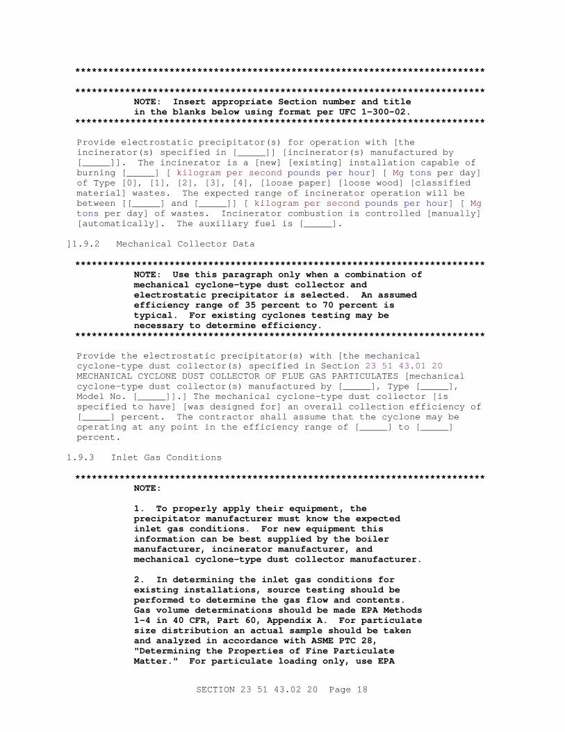
Provide electrostatic precipitator(s) for operation with [the incinerator(s) specified in [_____]] [incinerator(s) manufactured by [_____]]. The incinerator is a [new] [existing] installation capable of burning [_____] [ kilogram per second pounds per hour ] [ Mg tons per day] of Type [0], [1], [2], [3], [4], [loose paper] [loose wood] [classified material] wastes. The expected range of incinerator operation will be between [[_____] and [_____]] [ kilogram per second pounds per hour ] [ Mg tons per day] of wastes. Incinerator combustion is controlled [manually] [automatically]. The auxiliary fuel is [_____].
] 1.9.2 Mechanical Collector Data
**************************************************************************NOTE: Use t hi s par agr aph onl y when a combi nat i on of mechani cal cycl one- t ype dust col l ect or and el ect r ost at i c pr eci pi t at or i s sel ect ed. An assumed ef f i c i ency r ange of 35 per cent t o 70 per cent i s t ypi cal . For exi st i ng cycl ones t est i ng may be necessar y t o det er mi ne ef f i c i ency.
**************************************************************************
Provide the electrostatic precipitator(s) with [the mechanical cyclone-type dust collector(s) specified in Section 23 51 43.01 20 MECHANICAL CYCLONE DUST COLLECTOR OF FLUE GAS PARTICULATES [mechanical cyclone-type dust collector(s) manufactured by [_____], Type [_____], Model No. [_____]].] The mechanical cyclone-type dust collector [is specified to have] [was designed for] an overall collection efficiency of [_____] percent. The contractor shall assume that the cyclone may be operating at any point in the efficiency range of [_____] to [_____] percent.
1.9.3 Inlet Gas Conditions
**************************************************************************NOTE:
1. To pr oper l y appl y t hei r equi pment , t he pr eci pi t at or manuf act ur er must know t he expect ed i nl et gas condi t i ons. For new equi pment t hi s i nf or mat i on can be best suppl i ed by t he boi l er manuf act ur er , i nci ner at or manuf act ur er , and mechani cal cycl one- t ype dust col l ect or manuf act ur er .
2. I n det er mi ni ng t he i nl et gas condi t i ons f or exi st i ng i nst al l at i ons, sour ce t est i ng shoul d be per f or med t o det er mi ne t he gas f l ow and cont ent s. Gas vol ume det er mi nat i ons shoul d be made EPA Met hods 1- 4 i n 40 CFR, Par t 60, Appendi x A. For par t i cul at e s i ze di st r i but i on an act ual sampl e shoul d be t aken and anal yzed i n accor dance wi t h ASME PTC 28, " Det er mi ni ng t he Pr oper t i es of Fi ne Par t i cul at e Mat t er . " For par t i cul at e l oadi ng onl y, use EPA
SECTION 23 51 43.02 20 Page 18
Met hod 5 or 17.
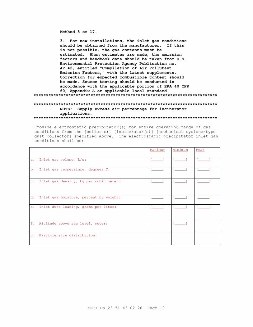
3. For new i nst al l at i ons, t he i nl et gas condi t i ons shoul d be obt ai ned f r om t he manuf act ur er . I f t hi s i s not possi bl e, t he gas cont ent s must be est i mat ed. When est i mat es ar e made, t he emi ssi on f act or s and handbook dat a shoul d be t aken f r om U. S. Envi r onment al Pr ot ect i on Agency Publ i cat i on no. AP- 42, ent i t l ed " Compi l at i on of Ai r Pol l ut ant Emi ssi on Fact or s, " wi t h t he l at est suppl ement s. Cor r ect i on f or expect ed combust i bl e cont ent shoul d be made. Sour ce t est i ng shoul d be conduct ed i n accor dance wi t h t he appl i cabl e por t i on of EPA 40 CFR 60, Appendi x A or appl i cabl e l ocal st andar d.
**************************************************************************
**************************************************************************NOTE: Suppl y excess ai r per cent age f or i nci ner at or applications.
**************************************************************************
Provide electrostatic precipitator(s) for entire operating range of gas conditions from the [boiler(s)] [incinerator(s)] [mechanical cyclone-type dust collector] specified above. The electrostatic precipitator inlet gas conditions shall be:
Maximum Minimum Peak
a. Inlet gas volume, L/s: [_____] [_____] [_____]
b. Inlet gas temperature, degrees C: [_____] [_____] [_____]
c. Inlet gas density, kg per cubic meter: [_____] [_____] [_____]
d. Inlet gas moisture, percent by weight: [_____] [_____] [_____]
e. Inlet dust loading, grams per liter: [_____] [_____] [_____]
f. Altitude above sea level, meter: [_____]
g. Particle size distribution:
SECTION 23 51 43.02 20 Page 19
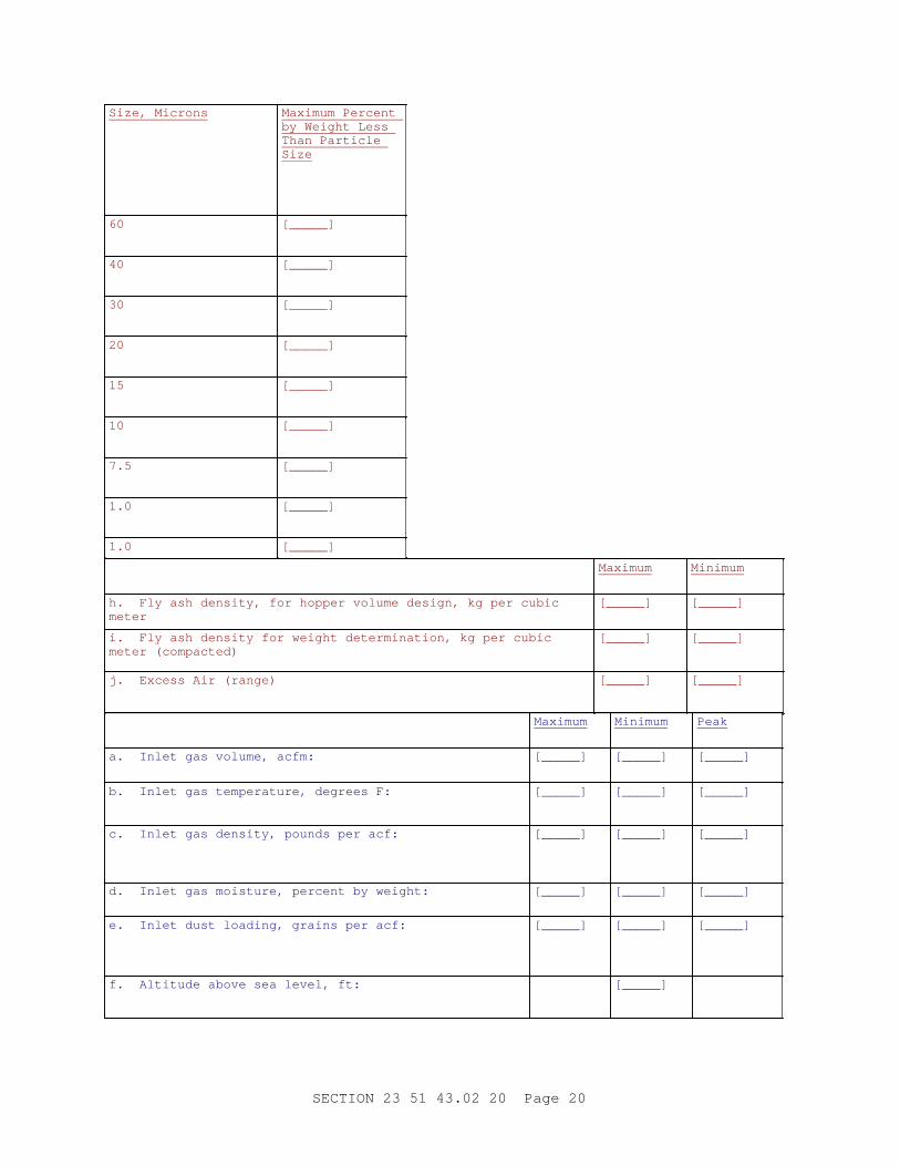
Size, Microns Maximum Percent by Weight Less Than Particle Size
60 [_____]
40 [_____]
30 [_____]
20 [_____]
15 [_____]
10 [_____]
7.5 [_____]
1.0 [_____]
1.0 [_____]
Maximum Minimum
h. Fly ash density, for hopper volume design, kg per cubic meter
[_____] [_____]
i. Fly ash density for weight determination, kg per cubic meter (compacted)
[_____] [_____]
j. Excess Air (range) [_____] [_____]
Maximum Minimum Peak
a. Inlet gas volume, acfm: [_____] [_____] [_____]
b. Inlet gas temperature, degrees F: [_____] [_____] [_____]
c. Inlet gas density, pounds per acf: [_____] [_____] [_____]
d. Inlet gas moisture, percent by weight: [_____] [_____] [_____]
e. Inlet dust loading, grains per acf: [_____] [_____] [_____]
f. Altitude above sea level, ft: [_____]
SECTION 23 51 43.02 20 Page 20
Maximum Minimum Peak
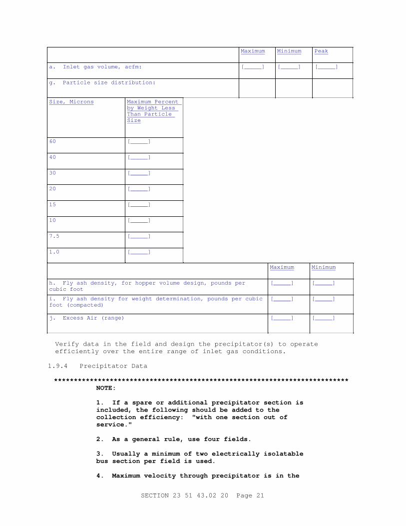
a. Inlet gas volume, acfm: [_____] [_____] [_____]
g. Particle size distribution:
Size, Microns Maximum Percent by Weight Less Than Particle Size
60 [_____]
40 [_____]
30 [_____]
20 [_____]
15 [_____]
10 [_____]
7.5 [_____]
1.0 [_____]
Maximum Minimum
h. Fly ash density, for hopper volume design, pounds per cubic foot
[_____] [_____]
i. Fly ash density for weight determination, pounds per cubic foot (compacted)
[_____] [_____]
j. Excess Air (range) [_____] [_____]
Verify data in the field and design the precipitator(s) to operate efficiently over the entire range of inlet gas conditions.
1.9.4 Precipitator Data
**************************************************************************NOTE:
1. I f a spar e or addi t i onal pr eci pi t at or sect i on i s i ncl uded, t he f ol l owi ng shoul d be added t o t he col l ect i on ef f i c i ency: " wi t h one sect i on out of service."
2. As a gener al r ul e, use f our f i el ds.
3. Usual l y a mi ni mum of t wo el ect r i cal l y i sol at abl e bus sect i on per f i el d i s used.
4. Maxi mum vel oci t y t hr ough pr eci pi t at or i s i n t he
SECTION 23 51 43.02 20 Page 21
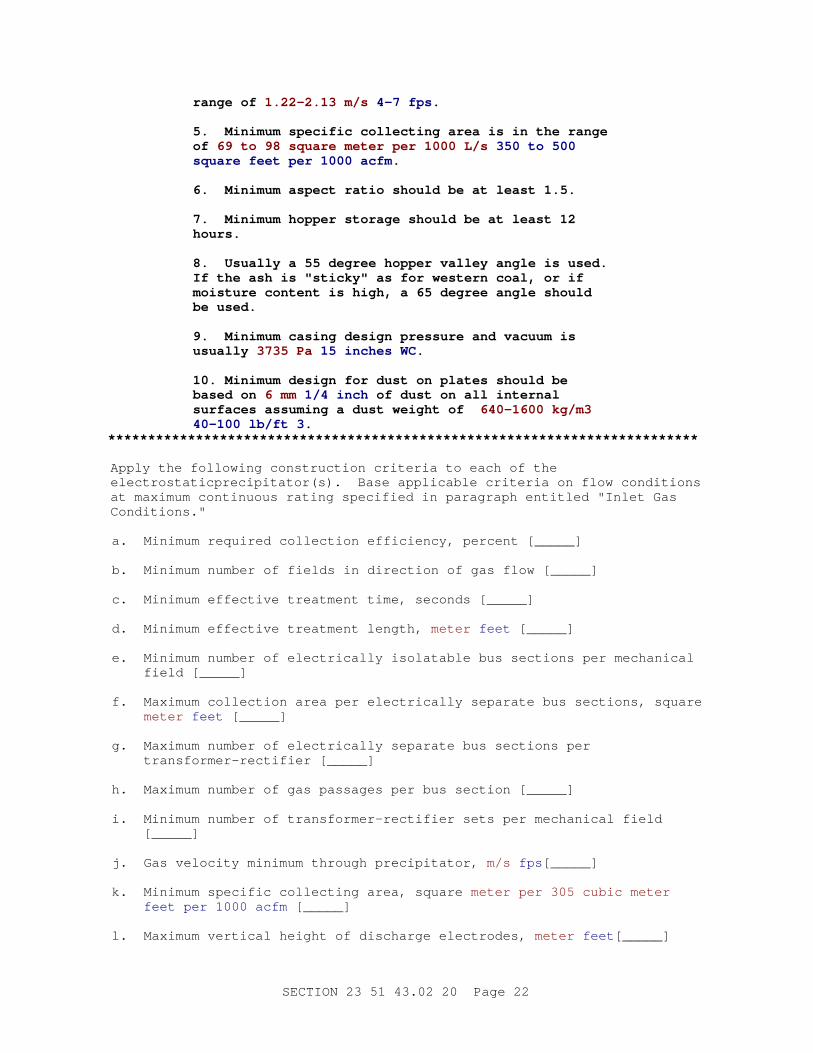
r ange of 1. 22- 2. 13 m/ s 4- 7 f ps.
5. Mi ni mum speci f i c col l ect i ng ar ea i s i n t he r ange of 69 t o 98 squar e met er per 1000 L/ s 350 t o 500 squar e f eet per 1000 acf m.
6. Mi ni mum aspect r at i o shoul d be at l east 1. 5.
7. Mi ni mum hopper st or age shoul d be at l east 12 hours.
8. Usual l y a 55 degr ee hopper val l ey angl e i s used. I f t he ash i s " st i cky" as f or west er n coal , or i f moi st ur e cont ent i s hi gh, a 65 degr ee angl e shoul d be used.
9. Mi ni mum casi ng desi gn pr essur e and vacuum i s usually 3735 Pa 15 i nches WC.
10. Mi ni mum desi gn f or dust on pl at es shoul d be based on 6 mm 1/ 4 i nch of dust on al l i nt er nal sur f aces assumi ng a dust wei ght of 640- 1600 kg/ m3 40- 100 l b/ f t 3.
**************************************************************************
Apply the following construction criteria to each of the electrostaticprecipitator(s). Base applicable criteria on flow conditions at maximum continuous rating specified in paragraph entitled "Inlet Gas Conditions."
a. Minimum required collection efficiency, percent [_____]
b. Minimum number of fields in direction of gas flow [_____]
c. Minimum effective treatment time, seconds [_____]
d. Minimum effective treatment length, meter feet [_____]
e. Minimum number of electrically isolatable bus sections per mechanical field [_____]
f. Maximum collection area per electrically separate bus sections, square meter feet [_____]
g. Maximum number of electrically separate bus sections per transformer-rectifier [_____]
h. Maximum number of gas passages per bus section [_____]
i. Minimum number of transformer-rectifier sets per mechanical field [_____]
j. Gas velocity minimum through precipitator, m/s fps [_____]
k. Minimum specific collecting area, square meter per 305 cubic meter feet per 1000 acfm [_____]
l. Maximum vertical height of discharge electrodes, meter feet [_____]
SECTION 23 51 43.02 20 Page 22
m. Maximum vertical height of collecting electrodes, meter feet [_____]
n. Range of plate spacing, mm inches [_____] to [_____]
o. Minimum discharge electrode cross-sectional area, square mm inches [_____]
p. Maximum horizontal length of each electrical field, meter feet [_____]
q. Minimum aspect ratio [_____]
r. Maximum pressure from [_____] to [_____] Pa inches water gage [_____]
s. Minimum hopper storage capacity, each hopper, hours [_____]
t. Minimum hopper storage capacity, each hopper, cubic meter feet [_____]
u. Minimum hopper valley angle, degrees from horizontal [_____]
v. Minimum number of hoppers for each electrical field [_____]
w. Minimum casing design pressure at [_____] degrees C F , Pa inches water gage [_____]
x. Minimum casing design vacuum at [_____] degrees C F , Pa inches Hg [_____]
y. Minimum casing design temperature, degrees C F [_____]
z. Minimum insulator design temperature, degrees C F [_____]
aa. Minimum design wind load, kg per square meter pounds per square foot [_____]
ab. Minimum design snow load, kg per square meter pounds per square foot [_____]
ac. Minimum design live load, kg per square meter pounds per square foot [_____]
ad. Minimum design load for dust on internal surfaces, kg pounds [_____]
1.9.5 Breeching
Provide breeching, stiffeners, bracing, supports, hangers, supporting steel, expansion joints and heat insulation between the [_____] and [_____]. Design the breeching to withstand internal pressures between plus 3735 to minus 6225 Pa 15 to minus 25 inch water gage. Include turning vanes in breeching as recommended by the report on model test. Provide self-cleaning type breeching to prevent dust accumulation. Provide expansion joints to give the breeching sufficient flexibility under thermal changes. Provide suitable supports and guides to eliminate transverse loading of flexible expansion joints.
1.9.6 Coordination
Coordinate design parameters and controls of precipitator between precipitator manufacturer and manufacturers of equipment which will interface with, or affect, system operation. Design the precipitator for
SECTION 23 51 43.02 20 Page 23
operation with the [boiler] [incinerator] [and the mechanical cyclone type dust collection] specified to assure that the collection efficiency specified is attained.
1.9.7 Electrostatic Dust Collector System
Submit operation and maintenance data for electrostatic dust collector system in accordance with Section 01 78 23 OPERATION AND MAINTENANCE DATA.
1.10 AMBIENT ENVIRONMENT IN VICINITY OF ELECTRICAL EQUIPMENT
Guarantee that electrical equipment mounted external to the precipitator housing shall perform satisfactorily during normal operation of the [boiler] [incinerator] at loads within its rated limits and during start-up and shutdown, with an ambient environment of [[_____] to [_____]] degrees C F and [[_____] to [_____]] percent relative humidity, and exposure, including solar effects. Electrical equipment shall include the following:
a. Motors, motor starters, controllers, and controls
b. Transformer-rectifiers
c. Rapper coils
d. Insulators
e. High voltage bus
f. Raceway and conductors interconnecting precipitator electrical equipment
g. Pressure switches
h. Heater contactors.
1.11 MISCELLANEOUS
Provide installation complete in accordance with this specification and as shown and include the following:
a. Wiring, conduits, fittings, supports, and grounding of electrical equipment in accordance with Division 26, "Electrical."
b. Special tools and devices required for operating, adjusting, repairing, and maintaining the air pollution control with their accessories.
c. Warning signs , of an approved permanent type, where required for the safety of operating personnel.
d. Bronze grounding lugs outside each access door into the precipitator.
1.12 DELIVERY OF MODEL
The model used for testing shall remain the property of the Government. Deliver the model including a support table to the Contracting Officer within six months after Government acceptance of the full size units.
SECTION 23 51 43.02 20 Page 24

PART 2 PRODUCTS
2.1 MATERIALS
Parts exposed to the flue gas of materials having physical suitable for the service and able to withstand the abrasive and chemical action of the flue gas and fly ash. Make parts subject to deterioration easily accessible for inspection, maintenance, or replacement. The materials used shall conform to the following:
**************************************************************************NOTE: Use ASTM A242/ A242M st eel when mat er i al i s subj ect ed t o cont i nuous t emper at ur es of 204 degr ees C 400 degr ees F or hi gher .
**************************************************************************
a. Housing plate and stiffeners: [ ASTM A242/A242M , Type 1]
**************************************************************************NOTE: Use ASTM A242/ A242M st eel when mat er i al i s subj ect ed t o cont i nuous t emper at ur es of 204 degr ees C 400 degr ees F or hi gher .
**************************************************************************
b. Hoppers: [ ASTM A242/A242M , Type 1] [ ASTM A276/A276M ]
**************************************************************************NOTE: Use ASTM A242/ A242M st eel when mat er i al i s subj ect ed t o cont i nuous t emper at ur es of 204 degr ees C 400 degr ees F or hi gher .
**************************************************************************
c. Discharge electrodes: [ ASTM A242/A242M , Type 1]
**************************************************************************NOTE: Use ASTM A242/ A242M st eel when mat er i al i s subj ect ed t o cont i nuous t emper at ur es of 204 degr ees C 400 degr ees F or hi gher .
**************************************************************************
d. Collecting surfaces: [ ASTM A242/A242M , Type 1]
**************************************************************************NOTE: Use ASTM A242/ A242M st eel when mat er i al i s subj ect ed t o cont i nuous t emper at ur es of 204 degr ees C 400 degr ees F or hi gher .
**************************************************************************
e. Gas distribution devices: [ ASTM A242/A242M , Type 1]
**************************************************************************NOTE: Use ASTM A242/ A242M st eel when mat er i al i s subj ect ed t o cont i nuous t emper at ur es of 204 degr ees C 400 degr ees F or hi gher .
**************************************************************************
f. Structural and miscellaneous steel: [ ASTM A242/A242M , Type 1]
SECTION 23 51 43.02 20 Page 25

2.2 STRUCTURAL SUPPORTS
**************************************************************************NOTE: Use 6 mm 1/ 4 i nch t hi ck st eel f or t emper at ur es over 260 degr ees C 500 degr ees F. Det ai l st r uct ur al suppor t s on dr awi ngs.
**************************************************************************
Provide steel support structures for the precipitator as [indicated] [specified herein]. Provide the precipitator with column extensions or stubs to project from the precipitator internal support system to the support structure. Provide column extensions or stubs of adequate length to provide clearance between the precipitator casing and hoppers and the support frame beams. Provide sufficient clearance to permit the insulation and casing to be installed and to accommodate the extremes of displacement caused by thermal expansion. Support precipitator components from the precipitator internal support system. Provide additional grid steel required at the unit for support of precipitator components. Anchor the precipitator on its centerlines and allow to expand in both directions. Provide slide plates for installation between the precipitator free support points and the support structure. [Design the precipitator supports for seismic probability zone [3][4] in accordance with Section 22 05 48.00 20 MECHANICAL SOUND VIBRATION AND SEISMIC CONTROL.] Fabrication and erection of structural steel shall conform to AISC 360 .
2.3 ELECTRICAL REQUIREMENTS
2.3.1 Electrical Scope of Work
The work covered by this section consists of providing, adjusting, testing, and placing in operation electrical equipment and materials which are an integral part of the electrostatic precipitator provided under this section.
2.3.1.1 Material and Workmanship
Material and workmanship in factory assembled equipment, unless indicated or specified otherwise, shall conform to Division 16, "Electrical." Include interconnecting conduit and wire, grounding, and the electrical connection of the mechanical equipment to the electrical power circuit under Division 16, "Electrical."
2.3.1.2 Electrical Supply Voltage
Provide supply voltage of [_____] volt, three phase and [_____] volt, single phase, 60 hertz. Balance single phase loads on three phase systems. Except as specified herein, design all equipment for energization from a [_____] volt, single phase, 60 hertz electrical supply.
2.3.1.3 Transformers
Supply transformers and accessory equipment as required to convert the [[_____] volt, three phase] [[_____] volt, single phase], 60 hertz electrical supply to those voltages required.
2.3.2 Equipment Enclosure Heaters
Provide outdoor equipment enclosures with space heaters to prevent condensation of moisture within the equipment enclosures. Space the
SECTION 23 51 43.02 20 Page 26

heaters away and thermally insulate from close painted surfaces. Control the heaters by an adjustable thermostat set to deenergize the heaters when the temperature rises to 35 degrees C 95 degrees F , and to energize the heaters when the temperature decreases to 29 degrees C 85 degrees F . The space heaters shall not interfere with normal entrance of cables into the enclosures or equipment within the enclosure.
2.3.2.1 Equipment Enclosure Nameplates
Provide equipment enclosures and associated switches, indicating lights, meters, and devices with nameplates.
2.3.2.2 Equipment Enclosure Grounding
Provide equipment enclosures with a ground bus and connectors in accordance with National Electrical Code. Connect electrical equipment to the grounding system specified in Division 16, "Electrical."
2.3.2.3 Insulation and Weatherproofing
**************************************************************************NOTE: Use t hi s par agr aph onl y when equi pment i s exposed t o t he at mospher e.
**************************************************************************
Insulate and weatherproof electrical enclosures exposed to the atmosphere. The enclosures shall conform to specification for insulation and enclosure for roof housing in paragraph entitled "Housing."
2.3.2.4 Wiring
Wiring design and installation shall be in accordance with NFPA 70 and as specified.
2.3.3 Transformer-Rectifier (T-R) Set
**************************************************************************NOTE: T- R vol t age shoul d be 50 KV DC aver age as a mi ni mum. Sump must be cover ed and pi ped t o an oi l - wat er separ at or i f pent house i s not cover ed by a weat her encl osur e.
**************************************************************************
Enclose the high voltage rectifying equipment in the sealed transformer case to form a single enclosure. The enclosure shall meet the requirements of NEMA Type 3R construction as described in NEMA ICS 6 . Provide oil-filled, air-cooled type transformer designed and shielded for precipitator service. Equip the transformer case with, at a minimum, the following items: connection box, grounding connection, filling connection, drain and sampling valves, thermometer, oil and vacuum gages, and high temperature alarm. Provide sump to contain the oil which may leak from the transformer. Provide rectifier with concentric pipe and guard conductors between power supply and precipitator. Voltage supply shall be rated for [_____] volts. T-R capacity shall be [_____] KVA maximum. T-R output voltage rating shall be [_____] kV minimum. T-R shall operate at 60 percent to 100 percent of its current rating at normal operating conditions.
SECTION 23 51 43.02 20 Page 27
2.3.3.1 Rectifier
Provide oil immersed, solid state silicone type rectifier. Mount within the transformer case and equip with necessary surge equalizers and suppressors. Arrange interior parts to facilitate circulation of oil for adequate cooling.
2.3.3.2 Grounding Switches
Provide each transformer-rectifier set with a five-position grounding switch to permit grounding of both bushings; full-wave power to one bushing, grounding of the other bushing and vice versa; half-wave power to both bushings. Provide a bus duct between the power supply and the precipitator. Do not connect more than two bus sections to a single transformer-rectifier set; connect each bus section to a single bushing and connect each bushing to only one bus section.
2.3.3.3 Transformer Oil
Provide insulating mineral oil, PCB free, kV rated with required dielectric rating. Sample the oil after installation and test in accordance with ASTM D923 and ASTM D877/D877M. If the oil does not meet the ASTM specification, dry and filter until it meets or exceeds the requirements.
2.3.4 Control Cabinet
Provide controls for the high voltage precipitator supply in control cabinets and include all regulating devices. Provide control cabinets that are completely wired, self-ventilated, free standing, and enclosed in a grounded casing. Maintain cabinet at positive pressure using a fan powered by a 120 volt, single-phase motor with a power output of not less than [0.093 kW] [1/8 hp] [_____]. Filter pressurizing air with a filter that is not less than 98.5 percent efficient for dust particles one micron or larger. Equip control cabinet and T-R with a safety key interlock. Construct the control cabinet in accordance with NEMA Type 12 as defined in NEMA ICS 6 . Each controller shall conform to NEMA ICS 1 and NEMA ICS 2 and contain, but not be limited to, the following:
a. Completely automatic solid state controller which will maintain a preset spark rate, maximum current, and maximum voltage; silicon controlled rectifiers driven by transistorized automatic controls with auxiliary manual capability. Provide the reactor in conjunction with the T-R set with a nominal impedance of 40 percent and additional taps at 50 percent and 60 percent impedance. Provide easily accessible taps to facilitate changing of tap position. The reactor shall hold inductance within 5 percent at 2.5 times rated current at 40 percent impedance.
b. Full range control on both manual and automatic. Field adjustments to the automatic control shall be maximum current, maximum voltage, and spark rate set point.
c. Indicators, meters, and protection.
d. High voltage start and stop pushbuttons.
e. Thermal line breaker with undervoltage coil and adjustable magnetic trip.
SECTION 23 51 43.02 20 Page 28
f. Transformer primary AC voltmeter.
g. Transformer primary AC ammeter.
h. Precipitator DC milliammeter.
i. Precipitator DC voltmeter.
j. Precipitator spark rate meter.
k. High temperature alarm indicator for T-R oil temperatures.
l. Auxiliary contacts for the attachment of a partable oscilloscope in order to observe both voltage and current wave forms on the high tension electrodes.
m. Inverse time over current relay for units rated higher than 300 milliamperes.
n. Static regulator to limit precipitator current during automatic control.
o. Alarm circuit interlock which opens when transformer primary circuit is energized.
p. Fused control disconnect for circuit breaker undervoltage coil and automatic control.
q. Manual automatic control select switch.
r. Thyristors with heat sink sized for operation without thyristor fan.
s. Automatic voltage control unit.
t. Three position selector switch with indicating lights; "LOCAL-MANUAL," "LOCAL-AUTO," and "REMOTE-AUTO" positions.
u. Adjustable memory.
v. Visual annunicator for each of the following conditions:
(1) T-R overload, one each transformer-rectifier.
(2) T-R undervoltage, one each transformer-rectifier.
(3) T-R high voltage short circuit and open circuit, one each transformer-rectifier.
(4) T-R open circuit, one each transformer-rectifier.
(5) High temperature indicator for T-R oil temperatures.
2.3.4.1 Arc Suppression Within the Precipitator
Controls shall prevent or minimize sparking. The device shall suppress an arc within 1/2 cycle and recover within two cycles to initial voltage before arc. Recovery rate shall be adjustable.
SECTION 23 51 43.02 20 Page 29
2.3.4.2 Auxiliary Alarm
Wire the control enclosure so that an isolated contact will close and alarm the local annunciator when any of the white indicating lights are illuminated for any of the T-R controls specified in paragraph entitled "Control Cabinet." Similarly provide an isolated contact to close and to alarm the local annunciator when any T-R control is not in the "REMOVE-AUTO" position.
2.3.4.3 Pushbutton Stations
**************************************************************************NOTE: Requi r e t hese i ndi cat or l i ght s i f r emot e i ndi cat i on i s r equi r ed.
**************************************************************************
Wire the start pushbuttons to function only when the three position selector switch is in the "LOCAL-MANUAL" or "LOCAL-AUTO" positions. In addition to shutting down the T-R, the stop pushbutton shall clear all alarm outputs, except the output indicating that T-R control is not remote. Startup, whether by local pushbutton or remote control, shall arm the alarm system. Provide remote control so that all T-R sets which have their three-position selector switches in the "REMOTE-AUTO" position may be stopped by pushbutton station on the main control panel. Provide output contacts for remote indication of the status of T-R which are in the "REMOTE-AUTO" mode. Provide indicating lights for each precipitator on the auxiliary boiler control panel as follows:
a. Green -- all units off.
b. Red -- all units on.
**************************************************************************NOTE: Requi r e amber l i ght i f sequent i al st ar t up i s required.
**************************************************************************
c. Amber - startup in progress.
2.3.4.4 Redundant Protective Devices
Provide redundant protective devices on controller connections to the transformer unit secondary circuit.
2.3.5 High Voltage System Wiring and Support Insulators
**************************************************************************NOTE: Use t hi s par agr aph f or " bus- duct " wi r i ng.
**************************************************************************
Provide wiring materials and insulators, including insulators for discharge electrode supports, required to electrically connect the T-R to the discharge electrodes. The high voltage lead from the rectifier to the discharge electrodes shall consist of a conductor in metal enclosed weatherproof bus duct. Furnish the bus duct complete with necessary insulators, duct supports and fittings, and supply formed to exact length ready for bolting to the equipment.
SECTION 23 51 43.02 20 Page 30

2.3.6 High-Voltage Leads
**************************************************************************NOTE: Use t hi s par agr aph f or " pi pe" wi r i ng.
**************************************************************************
Completely enclose high voltage leads to the precipitator in a grounded 16 gage minimum thickness sheet metal guard. The conductor shall be 20 mm 3/4 inch diameter, Schedule 40 iron pipe. Include equipment for the introduction of clean purging air in and around the support bushings to prevent dust buildup on the insulators. The high voltage conductor pipe shall have a union immediately connected to the T-R set so the T-R can be easily isolated from the precipitator. Connect the conductor pipe to the high voltage electrode frame by a removable wire lead.
2.3.7 High Voltage Insulators
Provide a minimum of four insulating support bushings for each electrical bus section. Compression-load the high tension insulators and install outside of the contaminated gas stream. Provide insulators of materials suitable for the temperature. Provide best process electrical glazed ceramic high density 85 percent alumina for temperatures below 454 degrees C 850 degrees F . Provide adequate access for removal and reinstallation of high voltage insulators. Provide four pad-eyes above each high voltage bus frame to facilitate lifting of the frame for precipitator maintenance. Attach pad-eyes to support beams. Each pad-eye and support beam shall be capable of supporting the entire weight of its respective high voltage bus frame. Provide other means for lifting high voltage bus frames if acceptable to Contracting Officer.
2.3.8 High Voltage Insulator and Pressurizing System Heaters
Provide a heating and pressurizing/purging system for the high voltage bus duct insulators and the discharge electrode support insulators. Furnish control devices to automatically energize the heaters, as required, when the temperature of the insulating support bushings falls below [107 degrees C] [225 degrees F] [_____] and deenergize the heaters when the temperature reaches [121 degrees C] [250 degrees F] [_____]. The system shall maintain an insulator temperature of 107 degrees C 225 degrees F when the precipitator is off line. Provide sufficient pressure to prevent the infiltration of dust and moisture laden air into the penthouse and to keep the inside of the high voltage insulators free from the flue gas. Supply a minimum of 47.20 L/s 100 acfm of heated, filtered air for each insulator. Direct the purge air downward in swirl pattern across the inside surface of each insulator. Provide a purge air filter of the disposable or cleanable type with a filter efficiency of not less than 98.5 percent for dust particles of one micron or larger. Provide remote annunciation for malfunctions of the heating and pressurizing system as specified in paragraph entitled "Annunication and Indication." Provide pressurizing fans, complete with electric motor, automatic backflow prevention dampers, inlet filters, and a relief device for filter bypass in case of blocked filters. Furnish a minimum of two fans for each pressurizing system. Provide pressurizing fans of equal capacity and requiring the same size motors. Upon less of any one fan, the remaining fans shall automatically pressurize the system as required to ensure continued normal operation of the precipitator. Provide a control system consisting of necessary relays, pressure switches, flow switches, and control devices. Factory mount control devices, except those requiring local mounting, and wire in an indoor NEMA ICS 6 , Type 12 floor-mounted
SECTION 23 51 43.02 20 Page 31

control enclosure. Provide each fan discharge duct with an airflow switch for use in fan control. Furnish locally mounted NEMA ICS 6 , Type 4 combination starters for the fans. Mount an "AUTO-ON" selector switch for each fan on the door of its associated local combination starter. Mount indicating lights for system status on the starter door. Provide each fan control circuit with a two-position, "AUTO-ON," selector switch. Provide a single normally open contact, which will close upon start up of the induced draft fans, when the selector switch is in the "AUTO" position. Provide relays as required to multiply this signal. Electrically isolate output contacts for controls motor starters.
2.3.9 Discharge Electrodes and Collecting Surfaces
Provide rigid frame type discharge electrodes. Rigid electrode, or weighted wire design precipitators are not acceptable. The discharge electrodes in each passageway shall run in a vertical direction and shall be supported by a welded pipe, tube, or channel frame. Provide the frame with vertical pipe, tube, or channel supports spaced at a maximum interval of 1.22 meters four feet . Also provide the frame with horizontal pipe, tube, or channel supports spaced at a maximum interval of 1.22 meters four feet . The electrodes shall have a cross-sectional area of not less than 16 square mm 0.025 square inches and not more than 64.52 square mm 0.10 square inches . Fabricate collecting surface from rolled seamless sheet of not less than 16 gage thickness. Collecting surface plate spacing shall be not less than 280 mm 11 inches or greater than 330 mm 13 inches . Support discharge electrodes and collecting surfaces as required to maintain proper alignment during operation. Support each main discharge electrode bus section support frame by four alumina support insulators. Design collecting surfaces so that deflection from a plane surface will not exceed plus or minus 6 mm 1/4 inch about any axis. Design and construct discharge electrodes and collecting surfaces to be readily located and aligned within plus or minus 6 mm 1/4 inch of the normal design position. Assemble the collecting surfaces at the factory. Factory assembled modules which can be shipped to the field for erection may be provided. Provide high voltage frames with sway braces or other devices as required to prevent swaying. Incorporate gas baffles into the collecting plates to provide a gas flow quiescent zone and to provide stiffening.
2.3.10 Rappers
Provide falling hammer collecting surface and discharge electrode rappers with individual hammers for each plate and frame. Design plate rappers for sequential rapping to prevent simultaneous rapping of plates and provide a minimum of 27 N.m 20 foot pounds of rapping force per plate. Design discharge electrode rappers for sequential rapping to prevent simultaneous rapping of frames and provide a minimum of 12.24 N.m 9 foot pounds of rapping force per frame. Provide solid steel rapper drive shafts with a minimum diameter of 50 mm 2 inches . Provide magnetic impulse gravity return gas distribution plate rappers with individual rappers for each plate or screen.
2.3.10.1 Rapper Controls
Rapper controls shall have adjustments for independent field repeat intervals and for independent field rest time.
SECTION 23 51 43.02 20 Page 32
2.3.10.2 Rapper Control System
Provide a rapper control system conforming to NEMA ICS 1 and NEMA ICS 2 consisting of necessary devices for the complete control of each rapper system. Factory install and wire the system for [indoor] [outdoor] installation in a NEMA [12] [3R] cabinet as described in NEMA ICS 6 and locate in [control house] [control room] [roof]. Provide outdoor mounted units finish painted for outdoor service, wind braced for [_____] km miles per hour wind and completely weatherproofed.
2.3.10.3 Rapper Disconnects
Provide disconnecting switches for individual rapper groups to deenergize for servicing.
2.3.10.4 Rapper High Voltage Spikes
Provide the rapper system with surge suppressors and other devices as required to eliminate high voltage spikes.
2.3.10.5 Rapper Annunciation
Provide remote annunciation for malfunctions of the rapping system as follows:
"White" light for rappers not operating (power failure).
2.3.11 Annunciation and Indication
2.3.11.1 Off-Limit Conditions
Provide annunciator and indication equipment for individual annunciation and indication of the following off-limit conditions:
a. T-R control trouble.
b. T-R overload, one each transformer-rectifier.
c. T-R undervoltage, one each transformer-rectifier.
d. T-R open circuit, one each transformer-rectifier.
e. T-R not in remote, one each transformer-rectifier.
f. Penthouse or insulator compartment air pressure low.
g. Loss of penthouse pressurizing airflow.
h. Rapper control failure, one each rapper control enclosure.
i. Low hopper temperature.
j. Insulator temperature below [107 degrees C] [225 degrees F] [_____].
k. Purge air filter clogged.
2.3.11.2 Annunciator
Provide annunciator with a station for each alarm input plus a minimum of
SECTION 23 51 43.02 20 Page 33
25 percent spare stations. Provide sufficient stations for annunciation such that the items of equipment that failed can be easily identified. Provide a backlighted window for each station with an engraved legend that will be readable by a [standing] [sitting] operator at the operating station. The unit shall be complete with test, audible silence, flasher reset, and lamp reset pushbuttons and audible device. Incorporate an adjustable time delay relay in the annunciator audible device circuit to cause automatic silencing of the device after a manually selected time period. The annunciator stations shall, however, remain lighted until the trouble is cleared. Provide solid-state type annunciator, suitable for 120 volts AC power supply with not less than 125 volts DC applied to the trouble contacts. Include one electrically isolated contact per window for remote annunciation. Provide positive oriented logic, 120 volts AC or 125 volts DC power supply for trouble contacts, and two lamps wired in parallel circuit per indicating window. Design annunciator alarm contacts to accept field contacts which close on alarm condition. Do not use contacts which open on alarm condition. Provide an auxiliary isolated contact for each station. The auxiliary contact action shall follow that of the field contact. Provide cover-mounted annunciator, test, audible silence, flasher reset, lamp reset, and acknowledge pushbuttons on a NEMA ICS 6 , Type 12 enclosure. Mount and wire the following devices inside the enclosure:
a. Annunciator audible device.
b. Fuse and fuse holder for annunciator power supply.
c. Fuse and fuse holder for the audible device.
d. Terminal blocks for connections to all external circuits.
2.3.12 Electrical Service Outlets
Provide a 20 amp, 110 VAC duplex ground fault NEMA 5 20R terminal duplex interrupter receptacle within 2.44 meters 8 feet of access doors except doors in the hot-roof and gas distribution plates. The receptacles on each precipitor level shall be on a separate circuit. Ground fault interrupters shall test and reset at the receptacle. Wire receptacles to provide individual receptacle protection such that no other receptacles are interrupted by an individual receptacle trip. The receptacle shall interrupt at 5 plus or minus 1 milliamp ground fault current. Provide specification grade or better receptacles and protect by weather tight covers. Provide a CS 6369 (Alpha Configuration) 50 amp, 3 pole, 4 wire , 120/250 VAC twist type receptacle in a FS box with a weatherproof cover (Hubbell SR-50 or approved equal - item may be provided as an integral assembly or as individual components) inside each weather enclosure on separate circuits. Provide a weatherproof 100 amp, 3 pole, 4 wire, 120/250 VAC, pin ad sleeve receptacle conforming to IEC 60309-3 within 15 meters 50 feet of each stack base and each precipitator base. Provide each of the 50 amp receptacles with an individual 50 amp, 208 VAC service. Provide each of the 100 amp receptacles with an individual 100 amp 208 VAC service.
2.4 HOUSING
Construct the precipitator housing, including inlet and outlet nozzles, of minimum 6 mm 1/4 inch thick steel plate and attach to appropriate structural steel supporting members. Plumb the housing within 10 mm 3/8 inch measured at top, bottom, and tie points, side to side, and front to
SECTION 23 51 43.02 20 Page 34

rear. The top of the precipitator support shall be flat within 1.50 mm 1/16 inch for area of support foot and at elevation within 3.18 mm 1/8 inch . Make provisions, including expansion joints if required, to allow for any expansion, differential expansion, and contraction that may occur. Design the expansion provisions to prevent escape of gas or inflow of ambient air. Provide a minimum of 1.50 meters 5 feet of vertical clearance inside the housing above the discharge electrodes and collecting surface frames to afford access for inspection and maintenance. Locate walkways internal to the housing between electrical fields, at the inlet to the first field, at the outlet to the last field, and as otherwise required to provide access to equipment located within the housing which may require inspection or maintenance. Provide access to internal walkways by two access openings located on opposite sides of the precipitator for each internal walkway. Access openings shall align directly with internal walkways and shall be unobstructed. The walkways shall provide a minimum passageway clearance of 762 mm 30 inches . Provide the housing with insulated, hinged, quick opening, access, inspection, and cleanout doors with gastight seals as required for proper operation and maintenance. Provide a minimum of one door above each bus section. The minimum access opening size shall be 460 by 600 mm 18 by 24 inches for rectangular openings and 600 mm 24 inches diameter for round openings. Provide key interlocks for openings through which personnel may come in contact with high voltage equipment to prevent opening before the electrical supply is deenergized. The housing shall be of all welded construction. Minimize the use of flanged or bolted joints. Use only where bolted assembly is required for adjustment or removal. Prevent structural members from acting as radiators, thereby reducing internal corrosion. The difference between the inside wall temperature at any point and the inlet gas temperature shall be less than 22 degrees C 40 degrees F .
2.4.1 Penthouse
Provide a penthouse to enclose the high voltage system support insulators. Enclose the entire top of the housing. Design the penthouse to withstand the effects of differential thermal expansion between the precipitator housing and the penthouse. Design the expansion provisions to assure an airtight penthouse. Weld gas tight. Check for leaks using smoke candles or other method approved by the Contracting Officer. Repair leaks by welding or repair of mechanical seals. Do not use caulking. Provide a minimum of 2 insulated, hinged, quick-opening access doors on the penthouse roof; one at each end of the roof. Provide penetrations, openings and hatches in or on the penthouse roof with mechanical seals or weld to provide a gas tight and watertight seal. Install calcium silicate insulation conforming to ASTM C533 over 12 gage steel pines stud welded on 610 mm 2 foot centers on the penthouse roof. Hold in place by 65 mm 2 1/2 inch square speed washers and closely fit around penetrations. Construct top surface of 6 mm 1/4 inch thick raised pattern plate conforming to ASTM A242/A242M , Type I to form a continuous walking surface. Provide support to bear not less than 488 kg per square meter 100 pounds per square foot live load. Provide additional support for equipment placed on the roof. Seal joints by continuous fillet or complete penetration groove welds as applicable. Weld appurtenances similarly to the plate. Provide top penetrations with a 50 mm two inch minimum extension above the plate and similarly weld to the plate. Slope the top surface to allow water runoff and to prevent pooling. Extend top surface at least 25 mm one inch beyond side insulation. Provide a 80 mm 3 inch fascia of 6 mm 1/4 inchsteel conforming to ASTM A242/A242M plate as a rain barrier. Provide a 80 mm 3 inch kickplate of 6 mm 1/4 inch steel conforming to ASTM A242/A242M plate around the perimeter of the top surface and provide adequate drain
SECTION 23 51 43.02 20 Page 35
holes to permit water runoff. Provide a safety rail on the top perimeter. Manufacture top surfaces of appurtenant structures with 6 mm 1/4 inch steel conforming to ASTM A242/A242M raised pattern floor plate in a manner similar to that specified herein including soffit and fascia dimensions. Aluminum casing materials shall conform to ASTM B209M ASTM B209.
2.4.2 Insulation Materials
**************************************************************************NOTE: For oper at i ng t emper at ur e r ange of 94 t o 260 degr ees C 201 t o 500 degr ees F use mi ni mum t hi ckness of 115 mm 4 1/ 2 i nches. For oper at i ng t emper at ur es 261 degr ees C 501 degr ees F and above use mi ni mum t hi ckness of 140 mm 5 1/ 2 i nches.
**************************************************************************
Insulate the precipitator housing, penthouse, and hoppers with ASTM C612 mineral fiber block or ASTM C592 mineral fiber blanket insulation. Insulate the roof with ASTM C533 calcium silicate block. Minimum insulation thicknesses shall be as follows:
a. Housing [_____] mm inches
b. Hoppers [_____] mm inches
c. Hot Roof [_____] mm inches
d. Penthouse [_____] mm inches .
2.4.3 Casing Materials
Casing except top surface casing, which might serve as personnel walking surface, shall be 1.27 mm 0.050 inch thick stucco embossed, 100 mm 4 inch rib, unpainted aluminum panel. Aluminum casing shall be ASTM B209M ASTM B209.
2.5 HOPPERS
Construct hopper plate of [Type 316 stainless steel conforming to ASTM A276/A276M ] [structural steel conforming to ASTM A242/A242M Type 1] and a minimum 6 mm 1/4 inch thick. Provide hoppers with ASTM A242/A242M baffles to prevent flue gas from bypassing the electrostatic field. Hoppers shall span no more than one electrical field. Provide hoppers with untapered fillet plates, constructed of cold rolled minimum 10-gage ASTM A276/A276M Type 316 stainless steel, in each corner. Extend the fillet plates the full length of the corner. Seal weld the fillet plates to the hopper walls. Provide closure plates at the top of the hopper at each corner to prevent flow into the area between the fillet plate and the hopper corner. Steel reinforcements not in contact with the gas or ash may be either ASTM A276/A276M Type 316 stainless steel or ASTM A242/A242M structural steel. If the latter is used, select welding rods specifically for the service and submit to the Contracting Officer for approval. Provide protection of rods against moisture.
2.5.1 Hopper Accessories
Provide key interlocked access doors on each hopper on both sides of any hopper baffle. Doors shall be in accordance with the requirements
SECTION 23 51 43.02 20 Page 36

specified herein. Hoppers shall have adequate flexibility for vibrators. Provide each hopper with two 100 mm 4 inch poke holes with a tee wash connection and screwed caps. Position poke holes to permit downward thrusts into the hopper. Provide a special plate reinforced "pounding area" on each hopper face for external manual vibrating. Each pounding plate shall be 300 by 300 by 25 mm 12 by 12 by 1 inch thick ASTM A36/A36M plate steel. Provide a work platform with stairs to each pounding area for units with pounding areas more than 1.50 meters five feet above ground. Do not insulate pounding plate. Finish insulation at this discontinuity. Provide a minimum 200 mm 8 inch diameter flanged fly ash outlet connection on each hopper to accept the fly ash transportation system equipment. Provide access hatch not less than 200 by 200 mm 8 by 8 inches for cleanout within 200 mm 8 inches above flange.
2.5.2 Hopper Vibrators
Provide each hopper with two vibrators set at the mid-height and on opposite sides. Interface vibrator controls with ash collection system to provide automatic vibrator operation only at the inception and during an evacuation cycle. Provide manual override control for hopper vibrators and evacuation system in hopper area and enclose in (a) case(s) to prevent accidental energization of systems. Place a warning over the vibrator manual control with the following inscription:
"WARNING: VIBRATOR CONTROL. DO NOT ACTIVATE UNLESS HOPPER EVACUATION SYSTEM IS OPERATING."
2.5.3 Hopper Heater System
Provide a hopper heater system for each precipitator.
2.5.3.1 Hopper Heater System Design
Provide the system complete with all material required for mounting. The system shall provide a 139 degrees C 250 degree F rise in temperature in the hopper, in the vicinity of the heaters, during offline and startup conditions. Size the system to provide a hopper skin temperature of not less than 177 degrees C 350 degree F when the insulation is in place during minimum ambient temperatures specified in Section 23 07 00 THERMAL INSULATION FOR MECHANICAL SYSTEMS. Design the system with a minimum heating safety factor of 1.1 and a minimum wind heat loss factor of 1.12. Design the system to provide maximum heater coverage between hopper stiffeners utilizing modular heaters and flexible blanket or tape heaters for the hopper throat heating. Heater modules shall cover not less than 33 percent of the hopper area. Cover the bottom portion of the hopper to the maximum extent possible, and extend at least 70 percent up the hopper height. Provide a two zone system. Comprise the lower zone of heaters located on the bottom one-third of hopper height including the throat heater; the upper zone shall include the remaining hopper heaters. Use flexible electric heating blankets or tapes, capable of withstanding 427 degrees C 800 degree F , where modular equipment will not fit. Provide only equipment designed to withstand natural and induced vibrations, plus shock loadings normally experienced during operation of the precipitator and ancillary equipment including manual rapping of the strike plates. Provide an individually, thermostatically controlled hopper heater system with adjustable setpoint and include power, control, and alarm components. Locate the low temperature and control thermocouples in the lower portion of each heater zone. Heater voltage shall be 480 volts AC. Control voltage shall be 120 volts AC.
SECTION 23 51 43.02 20 Page 37

a. Hopper Heater Module Design: Provide self-contained, modular heaters. Provide hopper heater modules which have a flexible heating face to conform to the irregularities of the hopper surface, providing contact between the heaters and the hopper, and providing maximum heat transfer. Provide low watt density design modules with a maximum of 0.0047 watts per square mm 3 watts per square inch of resistance element and with a minimum of six parallel resistance paths per heater. Continuous blanket type elements shall be deemed to meet the multipath requirement. Each module shall have dual heating elements. Both elements shall function during startup and offline conditions. To reduce power consumption and cycling while maintaining the hopper temperature during online operating conditions, controls shall automatically switch off one element in the lower zone and both elements in the upper zone without affecting the remaining element's operation. The hopper throat blanket heater shall have a single heating element and shall remain on during startup, offline, and online operating conditions. Each heating element in the module shall be capable of being operated at and shall be rated at 2690 watts per square meter 250 watts per square foot , but shall be designed to operate at 2152 watts per square meter 200 watts per square foot . Size wiring, circuits, and controls for 2690 watts per square meter 250 watts per square foot . Total power density shall be not less than 4303 watts per square meter 400 watts per square foot of heater module surface. Construct heating elements of 600 series stainless steel alloy or ni-chrome encased in a 20 gage minimum thickness aluminum or aluminized-steel mounting pan or casing. Provide two sets of heater pigtails for each module, one set of pigtails for each element and circuit. Provide multistrand copper pigtail and interconnecting wires with high temperature ( 454 degrees C 850 degree F ) insulation. Furnish heater pigtails with strain relief constructed to prevent damage to the heater modules due to rough handling. Provide pigtails of sufficient length to reach the terminal box. Splices are not permitted in pigtails from modules, tapes, or blankets to the terminal box. Perform hopper heater module voltage tests for each module, blanket, or tape for electrical integrity at 1,000 volts. Provide heating modules with metal labels firmly attached to the module listing the wattage and voltage of the module. Construct heating modules and mounting hardware of high temperature materials capable of withstanding 454 degrees C 850 degrees F . Insulate heating modules with high temperature woven glass cloth or mineral fiber. Mica or magnesium oxide insulated heaters are not acceptable.
b. Hopper Heater Installation: Heater modules shall provide maximum contact between the heaters and the hopper wall.
2.5.3.2 Hopper Heater Controls
**************************************************************************NOTE: Use t hese par agr aphs f or l ocal cont r ol onl y.
**************************************************************************
**************************************************************************NOTE: Use t hese par agr aphs f or mast er cont r ol onl y.
**************************************************************************
Control each hopper heater zone thermostatically with adjustable setpoint and provide complete including power, control and alarm components. Provide 120 volt AC adjustable type thermostats for monitoring hopper
SECTION 23 51 43.02 20 Page 38

temperature and locate in NEMA ICS 6 , Type 4 enclosures. For thermostatic control of the hopper heater system, provide a Master Hopper Heater Control Panel for each precipitator, a Local Hopper Heater Control Panel for each hopper, and a Local Hopper Heater Zone Terminal Box for each zone. Provide materials, tools, and labor required for connections of circuits and wiring between local hopper heater zone terminal boxes, local hopper heater control panels, and the master hopper heater control panels.
**************************************************************************NOTE: Use t hese par agr aphs f or l ocal cont r ol onl y.
**************************************************************************
a. Local Hopper Heater Zone Terminal Box: Provide hot-dipped galvanized NEMA ICS 6 , Type 4 hopper heater terminal boxes with terminal blocks for connection of heater pigtails and thermostat leads on each hopper for each hopper zone. Provide a sufficient number of terminals to connect the heater pigtails and thermocouples for each hopper zone.
**************************************************************************NOTE: Use t hese par agr aphs f or l ocal cont r ol onl y.
**************************************************************************
b. Local Hopper Heater Control Panel: Provide each precipitator with a local hopper heater control panel at each hopper. Locate at a regularly accessed area near each hopper. For each zone, provide each local hopper heater control panel with: terminal blocks for power, control, and alarm circuits, one control temperature thermostat, one low temperature alarm thermostat, magnetic contactor and alarm relay with two normally open contacts, and auxiliary relays for automatic operation of the heater system. Provide a 3-pole fused switched main disconnect device and a fused control transformer having a 120-volt AC secondary for each local hopper heater control panel. Provide thermostats with a set point range of 38 to 260 degrees C 100 to 500 degrees F . Measure hopper skin temperature using ungrounded, type J thermocouples. Provide each local hopper heater control panel cover with the following devices:
(1) "START UP," "ON LINE," "OFF," "AUTO" selector switch.
(2) 120 V "ON" red light with integral transformers, one each zone.
(3) 120 V "LO TEMP" alarm white light with integral transformer, one each zone.
(4) Device and enclosure nameplates.
Wire the selector switch for the following system operation:
(1) "START UP": Upper and lower zones all elements on (includes throat heater).
(2) "ON LINE": Single element lower zone on (includes throat heater).
(3) "OFF": All elements off.
(4) "AUTO": Control functions transfer to Master Hopper Heater Control Panel.
SECTION 23 51 43.02 20 Page 39
**************************************************************************NOTE: Use t hese par agr aphs f or mast er cont r ol onl y
**************************************************************************
c. Master Hopper Heater Control Panel: Provide panels containing relays, contactors, circuit breakers, control transformers, and other devices required for complete control of each precipitator hopper heater system. Locate Master Hopper Heater Control Panels with precipitator controls in the control room. Factory install and wire the panel components in a NEMA ICS 6 , Type 12 enclosure and include the following:
(1) A main circuit breaker.
(2) A circuit breaker and contactor alarm relay with two normally open contacts for each hopper zone. The contactor shall have a 120-volt operating coil.
(3) "START UP," "ON LINE," "OFF," selector switch for each hopper.
(4) 120 V red "ON" light and 120 V white "LO TEMP alarm light with integral transformers for each hopper zone.
(5) Auxiliary relays and equipment required for operation of the heating and alarm systems.
(6) Device and enclosure nameplates.
(7) Fused control transformer having a 120 volt AC secondary.
2.5.4 Fly Ash Level Alarms
Provide each hopper with a fly ash level alarm utilizing nuclear type detectors. The detectors shall be single point gamma source and detection units. Provide the detectors complete with separately mounted electronic units including local high level indicating light and relays for use with annunciation system herein specified. Provide relays rated at 10 amperes, 120 volts AC, or 125 volts DC continuous duty. Provide dustproof switch housing for hoppers and mount at one easily accessible location. Locate alarm indicators and detector and source electronics at the hopper control panel. Provide detector that is explosion proof, waterjacketed, and able to withstand vibration and temperatures up to 427 degrees C 800 degrees F . Provide the source with a lockable shutter mechanism operated by an external handle to totally isolate the beam when in the closed position. Furnish electrical wiring schematics. Electrical supply shall be 120 volts, single phase, 60 hertz. Provide two sensors for each hopper--one at the alarm level and one at the empty level. Locate alarm level at the 50 percent hopper capacity level.
2.5.4.1 Temperature Range Requirement
Level reproducibility shall be within one inch. Outdoor components shall operate between minus 40 and 93 degrees C 40 and 200 degrees F .
2.5.4.2 Cesium Source Safety Systems
Provide Cesium 137 source for each hopper. Design source head with a spring return off system in the event of remote cable actuator failure. Interlock source with hopper access doors to prevent entry into hopper
SECTION 23 51 43.02 20 Page 40
unless source has been secured. Hopper access door key shall only open one pair of hopper doors.
2.5.4.3 Hopper Level Indicator
Hopper level signals, based on hopper level status indicator system, shall report to a microprocessor through a coaxial cable system. Provide each hopper with two indicators, one for full and one for empty. A flashing light shall indicate a wall buildup. Loss of power for any period of time shall not require a recalibration. Provide NEMA ICS 6 , Type 4 enclosure for microprocessor.
2.5.4.4 Alarm System
Incorporate each group of detector units for a single electrostatic precipitator into the unit alarm system for its respective precipitator so that a high level in any hopper shall indicate as part of the unit alarm system.
2.6 ACCESS
2.6.1 Walkways
Provide walkways for inspection and maintenance of discharge electrode hanger points. Access doors and external walkways shall make routine inspection tours readily performable. Connect walkways, including roof, by stairways. Interconnect walkways at each level by walkways at the same level. Provide caged ladders as a means of secondary egress connecting all levels.
2.6.2 Doors
Provide every access door with a corresponding exterior walkway connected to the general system of platforms and walkways. Provide insulated, hinged, quick opening access, inspection, and clean out doors with gastight seals. Access doors, including hopper doors, and mechanical and electrical components shall be easily accessible from the walkway or provide with a permanent steel ladder or stairway to facilitate maintenance. Provide internal and external handholds at all access doors to facilitate entry.
2.6.3 Platforms, Walkways, and Ladders
Shop fabricate walkways, stairways, and ladders. Provide access to openings in both the precipitator and hoppers. Provide walkways in the casing interior as specified in paragraph entitled "Housing." Provide walkways, platforms, stairways, ladders, handrails, and kickplates on the penthouse roof and housing roof, as applicable, and as specified in paragraph entitled "Penthouse." Design platforms, ladders, and walkways support steel for live load specified herein. Design platforms to support a 488 kg per square meter 100 pound per square foot live load. Construct external walkways and platforms of steel conforming to ASTM A242/A242M raised pattern floor plate.
2.6.4 Maintenance
**************************************************************************NOTE: Pr ovi de 227 kg 500 pound cr ane unl ess T/ R set s ar e t o be r epl aced wi t h t he cr ane. I f used f or
SECTION 23 51 43.02 20 Page 41

T/ R r epl acement , s i ze f or T/ R wei ght .**************************************************************************
Provide jib crane as required to remove roof-mounted equipment. Load limits shall be [_____] kg pounds and the jib crane shall be properly signed for safety showing maximum load permitted.
2.6.5 Hot Dip Galvanizing
Hot dip galvanize platforms, walkways, stairways, ladders, handrails, and kickplates after fabrication in accordance with ASTM A123/A123M . Minimum galvanized coating per surface shall not be less than [_____] kg per square meter ounces/square foot .
2.6.6 Gas Distribution Devices
Provide the precipitator with inlet and outlet screens or baffles required to obtain proper gas distribution across the face of the precipitator as determined by model test study. Gas distribution devices shall contain removable 915 by 610 mm 3 by 2 feet panels on each screen or baffle for access between screens. Provide the precipitator with internal gas baffles as required to prevent gases from bypassing the treatment zone. Gas distribution velocities across the inlet to the precipitator shall have a root-mean-square deviation of no more than 15 percent and no flow shall exceed 125 percent of average flow velocity.
2.6.7 Interlocks
Provide a key type safety interlock system with sequential key arrangement on the precipitator housing and penthouse access doors, inlet and outlet nozzle access doors, rectifier enclosure access doors, transformer-rectifier grounding switch, hopper level indicator sources, hopper access doors, and control unit circuit breakers. No high voltage equipment shall be accessible without properly locking out the power supply and grounding the high voltage equipment. Keys shall not be able to be removed from the locks when access doors are open.
2.7 FABRICATION
Perform shop fabrication and assembly of steel structures in conformance with AISC Specifications, Codes and Standards. Field welding shall be shielded metal arc or submerged arc. Shop welding shall be shielded-metal arc, submerged arc, flux-core arc, or gas metal arc. Perform welding in conformance with the requirements of the AWS D1.1/D1.1M and AISC Specifications. Shop connections shall be welded, riveted, or bolted with high-strength bolts at the Contractor's option and as allowed by the seismic code. Unless restricted by consideration of clearance or seismic design criteria, show field connections as bolted friction type using ASTM A325M ASTM A325 or ASTM A490M ASTM A490 bolts and design to conform to AISC specification for "Structural Joints Using ASTM A325M ASTM A325 or ASTM A490M ASTM A490 Bolts." Form and weld handrails and do not exceed 6 feet from center-to-center of posts. Grind welds smooth and even with the surface of the pipe, remove weld splatter. Carefully form transitions at corners where change of direction of elevation occurs as required to provide continuous handrail. Clear columns or other vertical or horizontal projections by at least 80 mm 3 inches . Furnish plates and additional items as required for fastening to supporting members. Extend kickplates 100 mm 4 inches above top of grating and install at the edge of uncovered openings and at the edge of walkways and platforms. Construct
SECTION 23 51 43.02 20 Page 42
kickplates to allow water run-off. Shop fabricate as complete as possible and within standard industry practice. Leave large pieces unassembled only to the extent necessary for shipment.
2.8 PAINTING
Steel surfaces shall be dry and clean before painting. Remove grease, oils, and contaminants as outlined in SSPC SP 1 . Remove weld spatter and grind burrs smooth on cut edges and rough welds. Blast-clean surfaces after fabrication, in accordance with SSPC SP 6/NACE No.3 and profile depth of 0.038 to 0.051 mm 1.5 to 2.5 mils . Before any rust bloom forms, apply one coat, dry film thickness of 0.076 mm 3 mils , of any of the organic zinc-rich primers meeting the requirements of SSPC PS 12.01 , with a minimum of 82 percent zinc in the dry film. Apply primer in accordance with manufacturer's recommendations. Apply primer to steel surfaces except the areas within 50 mm two inches adjacent to field welds and surfaces specified to be hot-dip galvanized.
PART 3 EXECUTION
3.1 FACTORY INSPECTION
Any material or equipment used in the manufacture of the precipitator and found to be defective during inspection at the manufacturer's plant shall be either corrected or replaced as approved by the Contracting Officer before shipment. Acceptance at the factory shall not constitute final acceptance.
3.2 INSTALLATION
**************************************************************************NOTE: Revi se t hi s par agr aph as necessar y when i t i s desi r ed t o have t he pr eci pi t at or manuf act ur er i nst al l t he equi pment f ur ni shed.
**************************************************************************
The contractor shall install the equipment specified herein on foundations or structural-steel framework shown on the drawings or as specified elsewhere herein. Installation shall be in accordance with the manufacturer's recommendations.
3.3 MANUFACTURER'S FIELD REPRESENTATIVE
**************************************************************************NOTE: The per i od of i nst r uct i on shoul d be r educed onl y i f t he oper at i ng per sonnel have si gni f i cant exper i ence on i dent i cal equi pment .
**************************************************************************
The contractor shall provide the services of a field representative(s) specifically trained by the manufacturer to assist installers of their equipment. The field representative(s) shall be at the erection site during installation including unloading, hauling, storing, cleaning, erecting, and testing. The field representative(s) shall supervise the adjustment of all controls, control devices, and components supplied with the precipitator as necessary to place the precipitator in successful operation. The field representative(s) shall instruct the plant operators in the operation, care, and maintenance of the equipment. Provide a minimum of 10 working days advance notice to the Contracting Officer prior
SECTION 23 51 43.02 20 Page 43
to scheduling these instructions. Provide a total of [20] [_____] days instruction including [6] [_____] round trips to the jobsite. Provide training by field representative in precipitator theory and design, start-up, shut-down, operation, performance monitoring, performance evaluation, problem diagnosis, maintenance, inspection methods, safety, operations and maintenance plans.
3.4 FIELD TESTS AND INSPECTIONS
3.4.1 Delivery Inspection
Materials and equipment shall be inspected in accordance with the Contract Clauses. Inspections may be made to assure that equipment and installation comply with local and government requirements for equipment and safety as well as applicable specifications.
3.4.2 Post Installation Inspection
A factory service engineer employed by the precipitator manufacturer shall inspect the precipitator after installation is completed and prior to startup to verify that the unit is installed in conformance with the manufacturer's recommendations. Perform an air load test with precipitator readings recorded.
3.4.3 Performance Tests
Perform field performance tests by an independent testing organization acceptable to the Contracting Officer. Provide written notice to the Contracting Officer, at least 20 calendar days before scheduled test date, stating that equipment is being scheduled for test. Perform a trial run of 30 days minimum before actual test (operate boiler at least 60 to 90 percent load) to ensure that associated systems required for the test are ready. Perform boiler tune-up to optimum efficiency prior to performance test. The Contractor and the manufacturer's factory service engineer shall witness the test. Perform tests in accordance with applicable state or local methods. If no such methods or adaptations are required, then perform the tests in accordance with EPA 40 CFR 60 , Appendix A, Methods 1-5, 9 and 17. Perform tests at the maximum continuous rating for the inlet gas conditions specified in paragraph entitled "Inlet Gas Conditions" and, if applicable, at other operating conditions that are required for approval by the appropriate regulatory agency. Test the precipitator for efficiency by simultaneous testing of precipitator inlet and outlet emissions. Conduct the efficiency tests after the precipitator has been in operation for at least 45 days.
3.5 IDENTIFICATION
Fasten an aluminum, brass, or corrosion-resistant steel nameplate to the equipment in a readily visible location by means of stainless steel Series 300 rivets or sheet metal screws. The nameplate shall contain data such as the manufacturer's name, and model or series number. Indent or emboss the information in the metal. Offset the nameplate a sufficient amount to avoid being covered by insulation.
3.6 INSULATION INSTALLATION
3.6.1 General Insulation Requirements
Apply insulation with interruptions to permit access doors, inspection
SECTION 23 51 43.02 20 Page 44

doors, flanges, and other special features to be opened or removed for inspection or maintenance without disturbing the insulation. Provide boxouts around code stamping symbols and nameplates. Install double thickness insulation with the joints of the two layers staggered. Fill cracks, voids, and depressions in layers of insulation with suitable insulating cements before application of another layer of insulation or jacket application. Provide expansion joints in the insulation as required to allow for thermal expansion movements which might cause cracks or tears in the insulation. Install insulation between stiffeners and over stiffeners so that stiffeners are completely insulated. Install additional insulation or casing spacers between stiffeners so that a level surface is achieved. The intent of this insulating procedure is to prevent a direct metal path between the precipitator inside and ambient air. Securely wire and lace in place insulation using number 14 dead soft Type 302 stainless steel wire, conforming to ASTM A580/A580M .
3.6.2 Block and Mineral Fiberboard Insulation Installation
Secure block and mineral fiberboard insulation in place with insulation lugs spaces on not greater than 300 by 460 mm 12 by 18 inch centers. Provide stud type lugs welded in place. Reinforce blocks on the exterior face with expanded metal if necessary to prevent sagging or cutting of the insulation by the lacing wire. Securely wire block and mineral fiberboard insulation of the specified thickness in place over the entire surface by means of wire threaded through the lugs both ways, pulled tight with the ends of the wire loops twisted together with pliers, bent over, and carefully pressed into the surface of the insulation.
3.6.3 Mineral Fiber Blanket Insulation Installation
Secure mineral fiber blanket insulation in place with speed washers and impaling pins spaced on centers not exceeding 300 mm 12 inches . Provide mineral fiber blanket insulation with expanded metal reinforcement on the outer surface and wire mesh or expanded metal on the inner surface. Tightly butt sections of the blankets together and securely tie for maximum sealing at joints. Secure the blanket at joints to prevent peeling or bulging away from blanket edges. Do not reduce the design thickness of insulation when applying speed washers.
3.6.4 Housing Hot Roof
Install calcium silicate insulation conforming to ASTM C533 over 12 gage steel pins stud welded on 610 mm two foot centers to the surface to be insulated. Hold the insulation in place by 65 mm 2 1/2 inch square speed washers and closely fit around penetrations. Construct top surfaces of steel conforming to ASTM A242/A242M raised pattern plate not less than 6 mm 1/4 inch thick and suitably support to bear 488 kg per square meter 100 pounds per square foot live load. Seal joints by continuous fillet or complete penetration groove welds as applicable. Weld appurtenances similarly to the plate. Provide top penetrations with a 50 mm 2 inch minimum extension above the plate and similarly weld to the plate.
3.7 PROTECTION FROM INSULATION MATERIALS
Protect equipment and structures from damage from insulation materials. After completion of the work, clean, repair, and restore equipment and structures to their original state. Repair any casing which becomes corroded, discolored, or otherwise damaged by replacing of casing or other means acceptable to the Contracting Officer.
SECTION 23 51 43.02 20 Page 45
3.8 CASING INSTALLATION
3.8.1 Structural Steel Grid System
Install casing over exterior insulated surfaces on an aluminized structural steel grid system of subgirts designed, furnished, and installed by the contractor. Provide subgirts of sufficient size, gage, and depth to provide adequate support and a smooth exterior surface and weld to the equipment and structural support surfaces. Provide subgirts of sufficient depth to provide for application of the full thickness of insulation over the stiffeners, access doors, flanges, ribs, and other surfaces having uneven contours to provide a smooth finished surface. Provide subgirts on vertical and bottom surfaces at a maximum spacing of 1.22 meters 4 feet on centers. Provide subgirts on roof surfaces at a maximum spacing of 610 mm two feet on centers. Provide a roof surface system that will transmit an external 114 kg 250 pound walking load from the casing to the structural steel grid system without compression of the insulation material.
3.8.2 Access Openings
Closely fit insulation to fittings around access doors and other penetrations through the insulation. Neatly frame and flash to make weathertight and to create a pleasing appearance. Provide insulated hinged or lift-off doors designed for convenient opening or removal at nameplates, code stampings, nonprojecting connections, and access openings. Pitch access openings for water runoff and have flashing at door head as shown in SMACNA 1793.
3.8.3 Weatherproofing
Install casing with proper overlap to make the installation weathertight. Fabricate and fit the casing to ensure a neat appearance. Provide closures, flashings, and seals required. Provide the open ends of fluted sections with tightfitting closure pieces. Suitably form and install flashing so that water cannot enter and wet the insulation. Design and install flashing to readily drain any water that might enter. Weatherproof joints or openings in casing which cannot be effectively sealed from entry of moisture by application of an aluminum-pigmented sealer manufactured for this type of service.
3.8.4 Convection Stops
Provide steel channel or Z-girt convection stops on all vertical surfaces over 3.66 meters 12 feet tall. The maximum interval between convection stops shall be 3.66 meters 12 feet .
3.8.5 Casing Attachment
**************************************************************************NOTE: I f a separ at e i nsul at i on sect i on i s par t of t hi s speci f i cat i on, add a not e t o t hat sect i on t o i ndi cat e t hat i nsul at i on of t he pr eci pi t at or i s cover ed by t hi s sect i on.
**************************************************************************
Attach aluminum casing to the steel structural members by means of Number 14 stainless steel Series 300 self-tapping screws on 305 mm 12 inch
SECTION 23 51 43.02 20 Page 46
centers. Fasten vertical laps and flashing by means of 20 mm 3/4 inch Number 14 stainless steel Series 300 sheet metal screws on 305 mm 12 inch centers. Provide exposed screws with aluminum of stainless steel backed neoprene washers preassembled to screws. Do not compress insulation below nominal thickness when installing screws.
3.9 HEATER INSTALLATION
Thoroughly clean hopper surfaces prior to heater module, tape, or blanket installation. Install the heater module so the module surface contacts the hopper wall to the maximum extent possible. Provide heaters with necessary mounting hardware, channels, and brackets. Install throat heaters so the heater conforms to the surface of the throat and contacts the throat to the maximum extent possible. Do not overlap throat heaters. Hold throat heaters in place with high temperature ( 454 degrees C 850 degrees F ) glass tape or other means acceptable to the Contracting Officer. Completely cover the throat heater with the glass tape prior to lagging.
3.10 WIRE NUMBERS
Provide wire numbers on both ends of each wire appearing on the elementary diagram. Use space terminals for terminations. Markers shall be white plastic sleeves with black letters.
3.11 GALVANIC CORROSION PREVENTION
To prevent galvanic corrosion, prevent permanent contact of aluminum casing with copper, copper alloy, tin, lead, nickel, or nickel alloy including Monel metal. Where it is necessary to attach the casing to carbon steel or low alloy steel, paint the steel with zinc chromate primer. Then paint with aluminum paint suitable for surface temperatures encountered. Do not use lead base paint.
3.12 PAINTING
Provide field painting of those surfaces of the following equipment not in contact with the flue gas stream: precipitators, cyclones, fans, and breeching. Field paint as specified in Section 09 90 00 PAINTS AND COATINGS. Paint other equipment provided in this section; either field paint with paint systems conforming to Section 09 90 00 PAINTS AND COATINGS or paint with factory or shop painting systems conforming to the requirements specified in Section 23 03 00.00 20 BASIC MECHANICAL MATERIALS AND METHODS.
3.13 SCHEDULE
Some metric measurements in this section are based on mathematical conversion of inch-pound measurements, and not on metric measurements commonly agreed on by the manufacturers or other parties. The inch-pound and metric measurements shown are as follows:
Products Inch-Pound Metric
a. [_____] [_____] [_____]
-- End of Section --
SECTION 23 51 43.02 20 Page 47